service manual - xtreme manufacturing · the operation and safety manual for the forklift. •...
TRANSCRIPT

Service Manual XR Forward Reach
Forklifts
Xtreme Manufacturing, LLC 1415 West Bonanza Road
Las Vegas, NV 89106 (702) 858-2404
(702) 646-2196 (fax) www.xtrememanufacturing.com
IMPORTANT
Read and understand this manual before
operating or performing maintenance on these forklifts.
Copyright © 2011 – Xtreme Manufacturing, LLC
P/N 24933-000 Rev 02 – 08/11

Ask your supervisor to explain any operation, maintenance, or safety information that you do not fully understand.
Untrained personnel can cause death or severe injury. Do not operate or perform maintenance on a forklift until you have read and understand:
• The Operation and Safety Manual for the forklift.
• Chapter 2 of this Service Manual.
• The safety labels affixed to the forklift.
• Your employer's applicable work rules regarding the safety, operation, and maintenance of the forklift.
• Applicable federal, state, or local government regulations.
Untrained personnel can cause death or severe injury. Do not operate or work on a forklift until you have been trained in the safe operation and maintenance of the forklift.
– REPLACEMENT OF MANUALS –
Contact Xtreme Manufacturing, LLC, to obtain replacement Operation and Safety Manuals, Owner’s Service Manuals, Service Manuals, or Illustrated Parts Catalogs.
Xtreme Manufacturing, LLC 1415 West Bonanza Road
Las Vegas, NV 89106 (702) 851-3750
xtrememanufacturing.com

List of Effective Pages
List of Effective Pages
This manual consists of 280 pages as listed below:
Front cover page Inside front cover page Title page Pages A through B Pages i through x Pages 1-1 through 1-32 Pages 2-1 through 2-22 Pages 3-1 through 3-6 Pages 4-1 through 4-6 Pages 5-1 through 5-34 Pages 6-1 through 6-14 Pages 7-1 through 7-8 Pages 8-1 through 8-48 Pages 9-1 through 9-22 Pages 10-1 through 10-32 Pages 11-1 through 11-6 Pages 12-1 through 12-6 Pages Index 1 through Index 9 Pages A-1 through A-20 Inside back cover page Back cover page
Copyr ight © 2011 – Xtreme Manufactur ing Co.
Service Manual Rev 02 – 08/11 A P/N 24933-000
Service Bulletins
Service Bulletins
The following Service Bulletins have been incorporated in this manual:
Number Title Comments
Service Manual Rev 02 – 08/11 B P/N 24933-000

Table of Contents
Table of Contents
PARA. TITLE PAGE
List of Effective Pages ................................................................................................... A Service Bulletins ............................................................................................................ B Table of Contents........................................................................................................... i List of Illustrations ........................................................................................................ vi List of Tables ................................................................................................................. ix
SECTION 1 – GENERAL INFORMATION & SPECIFICATIONS....................................... 1-1
1-1 Scope of Manual ......................................................................................................... 1-1 1-2 Applicability ................................................................................................................. 1-1 1-3 Service Bulletins.......................................................................................................... 1-1 1-4 Related Technical Documentation .............................................................................. 1-2 1-5 Forklift Nomenclature.................................................................................................. 1-2 1-6 Component Data Plates.............................................................................................. 1-9 1-7 Lubricants and Fluids.................................................................................................. 1-13 1-8 Filters and Strainers .................................................................................................... 1-14 1-9 Forklift and Engine Specifications............................................................................... 1-15 1-10 Torque Wrench Use.................................................................................................... 1-29 1-11 Cap Screw Torque Values .......................................................................................... 1-29
SECTION 2 – MAINTENANCE & OPERATION SAFETY ................................................. 2-1
2-1 General ....................................................................................................................... 2-1 2-2 Safety Signal Words.................................................................................................... 2-1 2-3 Notes........................................................................................................................... 2-1 2-4 Safety Symbols ........................................................................................................... 2-2 2-5 Lockout/Tagout Procedure.......................................................................................... 2-6 2-6 General Maintenance Precautions.............................................................................. 2-7 2-7 Viton Seals .................................................................................................................. 2-7 2-8 Using Compressed Air Safely ..................................................................................... 2-8 2-9 Battery Handling and Maintenance............................................................................. 2-8 2-10 Engine Operation and Maintenance ........................................................................... 2-10 2-11 Fuel Handling and Maintenance ................................................................................. 2-11 2-12 California Proposition 65 Warnings............................................................................. 2-11 2-13 Functional Tests.......................................................................................................... 2-11 2-14 Safe Operation Checklist ............................................................................................ 2-12 2-15 Functional Test Checklist............................................................................................ 2-13 2-16 Load Handling ............................................................................................................. 2-14
Service Manual Rev 02 – 08/11 i P/N 24933-000

Table of Contents
Table of Contents – Cont.
PARA. TITLE PAGE
2-17 Picking Up a Load....................................................................................................... 2-16 2-18 Carrying a Load........................................................................................................... 2-16 2-19 Placing a Load ............................................................................................................ 2-16 2-20 Load Shift .................................................................................................................... 2-17 2-21 Proper Use of Forks.................................................................................................... 2-17 2-22 Prohibited Practices .................................................................................................... 2-17 2-23 Operator Hand Signals ............................................................................................... 2-18 2-24 Safety Labels .............................................................................................................. 2-19
SECTION 3 – MAINTENANCE SCHEDULE .................................................................... 3-1
3-1 Establishing a Preventive Maintenance Program....................................................... 3-1 3-2 Long-Interval Maintenance Requirements.................................................................. 3-6
SECTION 4 – AXLE CYLINDER AND OUTRIGGER LUBRICATION................................ 4-1
4-1 General Maintenance Safety ...................................................................................... 4-1 4-2 Using a Grease Gun ................................................................................................... 4-1 4-3 Lubricate Axle Cylinders and Outriggers .................................................................... 4-2
SECTION 5 – ENGINE ................................................................................................... 5-1
5-1 General Maintenance Safety ...................................................................................... 5-1 5-2 Check Engine Oil Level............................................................................................... 5-1 5-3 Check Engine Coolant Level....................................................................................... 5-3 5-4 Check for Oil and Coolant Leaks ................................................................................ 5-5 5-5 Check for Water in Fuel-Water Separator................................................................... 5-6 5-6 Empty Air Filter Dust Cup ........................................................................................... 5-8 5-7 Check Condition and Tension of Drive Belts .............................................................. 5-10 5-8 Change Engine Oil ...................................................................................................... 5-10 5-9 Replace Oil Filters....................................................................................................... 5-13 5-10 Replace Fuel Filter ...................................................................................................... 5-16 5-11 Check Specific Gravity of Coolant .............................................................................. 5-18 5-12 Drain and Flush Cooling System ................................................................................ 5-20 5-13 Replace Air Filter......................................................................................................... 5-22 5-14 Check Air Filter............................................................................................................ 5-24 5-15 Check Condition and Tension of Drive Belts .............................................................. 5-25 5-16 Check and Adjust Valve Tip Clearances..................................................................... 5-27 5-17 Check Engine Hoses and Connections ...................................................................... 5-29
Service Manual Rev 02 – 08/11 ii P/N 24933-000

Table of Contents
Table of Contents – Cont.
PARA. TITLE PAGE
5-18 Check Radiator Hoses and Connections.................................................................... 5-30 5-19 Check Engine Wiring and Connections ...................................................................... 5-31 5-20 Check for Oil, Coolant, and Fuel Leaks ...................................................................... 5-32
SECTION 6 – TRANSMISSION, AXLES, & DRIVE SHAFTS ........................................... 6-1 6-1 General Maintenance Safety ...................................................................................... 6-1 6-2 Using a Grease Gun ................................................................................................... 6-1 6-3 Lubricate Axle Grease Fittings.................................................................................... 6-2 6-4 Lubricate Drive Shafts................................................................................................. 6-4 6-5 Replace Transmission Filters and Fluids.................................................................... 6-6 6-6 Check Axle Oil Level ................................................................................................... 6-8 6-7 Check Wheel End Oil Level ........................................................................................ 6-11 6-8 Drain and Fill Axle Wheel End .................................................................................... 6-13
SECTION 7 – WHEELS & TIRES ................................................................................... 7-1 7-1 General Maintenance Safety ...................................................................................... 7-1 7-2 Check Wheel Lug Nut Torque..................................................................................... 7-1 7-3 Inspect Wheel/Tire Assembly ..................................................................................... 7-3 7-4 Replace Wheel/Tire Assembly.................................................................................... 7-4 7-5 Replace Tire................................................................................................................ 7-7
SECTION 8 – HYDRAULIC SYSTEM.............................................................................. 8-1 8-1 General Maintenance Safety ...................................................................................... 8-1 8-2 Hydraulics Maintenance Safety and Precautions ....................................................... 8-1 8-3 Handling Hydraulic Fluid ............................................................................................. 8-2 8-4 Making Leak-Free Connections .................................................................................. 8-2 8-4-1 Hose and Tubing Installation Practices....................................................................... 8-2 8-4-2 Operating Conditions .................................................................................................. 8-2 8-4-3 Maintenance Practices................................................................................................ 8-3 8-5 Keeping the Hydraulic System Clean ......................................................................... 8-4 8-6 Check Hydraulic Fluid Level ....................................................................................... 8-6 8-7 Change Hydraulic Fluid............................................................................................... 8-8 8-8 Replace Suction Strainer ............................................................................................ 8-10 8-9 Clean Hydraulic Reservoir Strainer............................................................................. 8-12 8-10 Replace Air Breather................................................................................................... 8-14 8-11 Replace High-Pressure Filter...................................................................................... 8-16 8-12 Replace Return Line Filter .......................................................................................... 8-19
Service Manual Rev 02 – 08/11 iii P/N 24933-000

Table of Contents
Table of Contents – Cont.
PARA. TITLE PAGE
8-13 Taking Hydraulic Fluid Sample ................................................................................... 8-21 8-14 Replacing a Hose........................................................................................................ 8-24 8-15 Tightening Loose Fittings............................................................................................ 8-27 8-16 Replace Cartridge Valve ............................................................................................. 8-27 8-17 Replace Cartridge Valve Solenoid .............................................................................. 8-30 8-18 Location of Hydraulic Components ............................................................................. 8-32 8-19 Distribution Manifold Hose Connections..................................................................... 8-32 8-20 Maintenance Requirements for Failed Pump ............................................................. 8-47
SECTION 9 – ELECTRICAL SYSTEM ........................................................................... 9-1
9-1 General Maintenance Safety ...................................................................................... 9-1 9-2 Battery Safety.............................................................................................................. 9-1 9-3 Battery Description...................................................................................................... 9-3 9-4 Battery Cable Description ........................................................................................... 9-3 9-5 Check Condition of Battery and Cables...................................................................... 9-3 9-6 Replace Battery........................................................................................................... 9-4 9-7 Inspect and Clean Battery........................................................................................... 9-8 9-8 Install Auxiliary Battery................................................................................................ 9-9 9-9 Electrical Center Assembly ......................................................................................... 9-11 9-10 Engine Relay Assembly .............................................................................................. 9-16 9-11 Replace a Relay.......................................................................................................... 9-18 9-12 Replace a Fuse........................................................................................................... 9-20
SECTION 10 – BOOM & ATTACHMENTS ...................................................................... 10-1 10-1 General Maintenance Safety ...................................................................................... 10-1 10-2 Using a Grease Gun ................................................................................................... 10-1 10-3 Boom and Attachment Lubrication.............................................................................. 10-2 10-4 Lubricate Boom Extend Chain .................................................................................... 10-6 10-5 Inspect Boom Chains.................................................................................................. 10-7 10-5-1 Chain Nomenclature ................................................................................................... 10-8 10-5-2 Visually Inspect Chain................................................................................................. 10-8 10-5-3 Measure Chain Edge Wear......................................................................................... 10-11 10-5-4 Measure Chain Elongation.......................................................................................... 10-13 10-6 Check and Adjust Boom Chain Tension ..................................................................... 10-15 10-7 Slide Blocks................................................................................................................. 10-16 10-8 Inspect Slide Blocks.................................................................................................... 10-16 10-9 Replace Slide Blocks .................................................................................................. 10-20
Service Manual Rev 02 – 08/11 iv P/N 24933-000

Table of Contents
Table of Contents – Cont.
PARA. TITLE PAGE
10-10 Inspect Boom Rollers.................................................................................................. 10-21 10-11 Fork Nomenclature...................................................................................................... 10-24 10-12 Measure Fork Flank Wear .......................................................................................... 10-26 10-13 Fork Inspection............................................................................................................ 10-28 10-14 Manually Retracting and Lowering Boom ................................................................... 10-29
SECTION 11 – CHECK-OUT PROCEDURES.................................................................. 11-1
11-1 Check Operation of Rear Axle Stabilization System................................................... 11-1
SECTION 12 – STORAGE & TRANSPORTATION .......................................................... 12-1 12-1 General Maintenance Safety ...................................................................................... 12-1 12-2 Preparing Engine for Long-Term Storage................................................................... 12-1 12-3 Preparing Forklift for Long-Term Storage ................................................................... 12-4 12-4 Transporting Forklift .................................................................................................... 12-5
APPENDIX – MAINTENANCE FORMS AND SAFETY TAGS .......................................... A-1
A-1 Preventive Maintenance and History Logs ................................................................. A-1 A-2 Pre-Operation Checklist .............................................................................................. A-1 A-3 Safety Tags ................................................................................................................. A-1 Maintenance Schedule...................................................................................................................... A-2 Maintenance History Log .................................................................................................................. A-8 Fork Inspection Log........................................................................................................................... A-11 Pre-Operation Checklist .................................................................................................................... A-13 Grease Fittings List ........................................................................................................................... A-15 Danger Tags ..................................................................................................................................... A-16 Condition Tags .................................................................................................................................. A-17 Notes ................................................................................................................................................. A-18
Service Manual Rev 02 – 08/11 v P/N 24933-000

Table of Contents
List of Figures
FIGURE TITLE PAGE
1-1 Forklift Nomenclature.................................................................................................. 1-3 1-2 Forklift Covers ............................................................................................................. 1-6 1-3 Forklift Cab.................................................................................................................. 1-7 1-4 Front Control Panel ..................................................................................................... 1-8 1-5 Side Control Console .................................................................................................. 1-9 1-6 Location of Chassis and Engine Data Plates.............................................................. 1-10 1-7 Location of Transmission Data Plates ........................................................................ 1-11 1-8 Location of Axle Data Plates....................................................................................... 1-12 1-9 SAE Grade 8 Bolt Markings ........................................................................................ 1-31
2-1 Danger and Condition Tags ........................................................................................ 2-6 2-2 Battery Disconnect Switch .......................................................................................... 2-7 2-3 Operator Hand Signals ............................................................................................... 2-18 2-4 Safety Labels .............................................................................................................. 2-19
3-1 Forklift Hourmeter ....................................................................................................... 3-1
4-1 Front and Rear Axle Cylinder Grease Fittings ............................................................ 4-3 4-2 Outrigger Grease Fittings – XR1245/1255/1267/1270/2045/2450 ............................. 4-4
5-1 Engine Oil Fill Cap and Dipstick.................................................................................. 5-2 5-2 Coolant Level Indicator ............................................................................................... 5-4 5-3 Radiator....................................................................................................................... 5-5 5-4 Fuel-Water Separator ................................................................................................. 5-7 5-5 Engine Air Filter Assembly.......................................................................................... 5-9 5-6 Oil Drain Plug and Dipstick ......................................................................................... 5-12 5-7 Recommended Engine Oil Viscosity Grades.............................................................. 5-12 5-8 Element-Type Oil Filter ............................................................................................... 5-14 5-9 Canister-Type Oil Filter ............................................................................................... 5-15 5-10 Fuel Filter Element ...................................................................................................... 5-17 5-11 Coolant Recovery Tank and Radiator Drain ............................................................... 5-19 5-12 Specific Gravity Chart ................................................................................................. 5-20 5-13 Cylinder Block Drain Plug ........................................................................................... 5-22 5-14 Checking Drive Belt Tension....................................................................................... 5-26 5-15 Checking and Adjusting Engine Valve Clearances..................................................... 5-28 5-16 Radiator Hoses and Connections ............................................................................... 5-31
Service Manual Rev 02 – 08/11 vi P/N 24933-000

Table of Contents
List of Figures – Cont.
FIGURE TITLE PAGE
6-1 Axle Grease Fittings.................................................................................................... 6-3 6-2 Drive Shaft Grease Fittings......................................................................................... 6-5 6-3 Transmission Plugs and Filters................................................................................... 6-7 6-4 Axle Differential and Trumpet Fluid Levels ................................................................. 6-10 6-5 Axle Wheel End........................................................................................................... 6-12
7-1 Lug Nut Torque Check Sequence............................................................................... 7-2 7-2 Wheel/Tire Assembly .................................................................................................. 7-4 7-3 Wheel Lug Nut Tightening Sequence ......................................................................... 7-6
8-1 Making Leak-Free Connections .................................................................................. 8-3 8-2 Hydraulic Filtration System ......................................................................................... 8-5 8-3 Hydraulic Reservoir Sight Gauge................................................................................ 8-7 8-4 Hydraulic Reservoir Fill Cap ....................................................................................... 8-8 8-5 Hydraulic Reservoir..................................................................................................... 8-10 8-6 Hydraulic Reservoir Strainer ....................................................................................... 8-12 8-7 Air Breather ................................................................................................................. 8-15 8-8 Location of Hydraulic Filters........................................................................................ 8-17 8-9 High-Pressure Filter .................................................................................................... 8-18 8-10 Return Line Filter......................................................................................................... 8-20 8-11 Taking Hydraulic Fluid Sample ................................................................................... 8-23 8-12 Hose Installation Guidelines ....................................................................................... 8-26 8-13 Cartridge Valve Solenoid ............................................................................................ 8-31 8-14 Location of Hydraulic Components ............................................................................. 8-32 8-15 Distribution Manifold Hose Connections – Model XR842........................................... 8-37 8-16 Distribution Manifold Hose Connections – Model XR1045......................................... 8-39 8-17 Distribution Manifold Hose Connections – Model XR1245......................................... 8-41 8-18 Distribution Manifold Hose Connections – Model XR1255......................................... 8-43
9-1 Battery and Cables...................................................................................................... 9-4 9-2 Battery Installation....................................................................................................... 9-6 9-3 Auxiliary Battery Installation........................................................................................ 9-10 9-4 Connecting Auxiliary Battery....................................................................................... 9-11 9-5 Electrical Center Relays and Fuses............................................................................ 9-12 9-6 Engine Relay Assembly .............................................................................................. 9-17 9-7 Correct Installation of Relays B through G, P/N 12068567 ........................................ 9-18
Service Manual Rev 02 – 08/11 vii P/N 24933-000
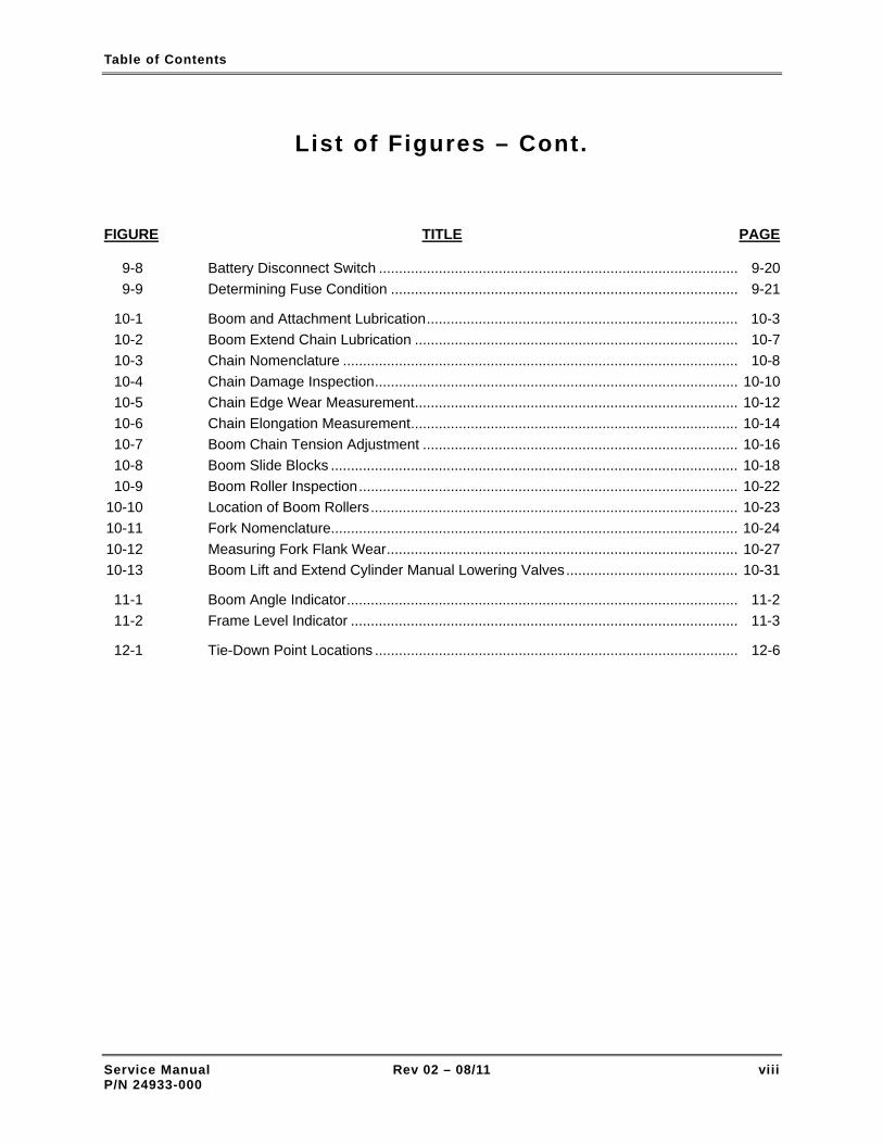
Table of Contents
List of Figures – Cont.
FIGURE TITLE PAGE
9-8 Battery Disconnect Switch .......................................................................................... 9-20 9-9 Determining Fuse Condition ....................................................................................... 9-21
10-1 Boom and Attachment Lubrication.............................................................................. 10-3 10-2 Boom Extend Chain Lubrication ................................................................................. 10-7 10-3 Chain Nomenclature ................................................................................................... 10-8 10-4 Chain Damage Inspection........................................................................................... 10-10 10-5 Chain Edge Wear Measurement................................................................................. 10-12 10-6 Chain Elongation Measurement.................................................................................. 10-14 10-7 Boom Chain Tension Adjustment ............................................................................... 10-16 10-8 Boom Slide Blocks ...................................................................................................... 10-18 10-9 Boom Roller Inspection............................................................................................... 10-22 10-10 Location of Boom Rollers............................................................................................ 10-23 10-11 Fork Nomenclature...................................................................................................... 10-24 10-12 Measuring Fork Flank Wear........................................................................................ 10-27 10-13 Boom Lift and Extend Cylinder Manual Lowering Valves........................................... 10-31
11-1 Boom Angle Indicator.................................................................................................. 11-2 11-2 Frame Level Indicator ................................................................................................. 11-3
12-1 Tie-Down Point Locations ........................................................................................... 12-6
Service Manual Rev 02 – 08/11 viii P/N 24933-000

Table of Contents
List of Tables
TABLE TITLE PAGE
1-1 Related Technical Documentation .............................................................................. 1-2 1-2 Lubricants and Fluids.................................................................................................. 1-13 1-3 Filter and Strainer Part Numbers ................................................................................ 1-14 1-4 Model XR620/621 Specifications ................................................................................ 1-15 1-5 Model XR842 Specifications ....................................................................................... 1-16 1-6 Model XR1045 Specifications ..................................................................................... 1-17 1-7 Model XR1245 Specifications ..................................................................................... 1-18 1-8 Model XR1255 Specifications ..................................................................................... 1-19 1-9 Model XR1267 Specifications ..................................................................................... 1-20 1-10 Model XR1270 Specifications ..................................................................................... 1-21 1-11 Model XR1534 Specifications ..................................................................................... 1-22 1-12 Model XR1642 Specifications ..................................................................................... 1-23 1-13 Model XR2034 Specifications ..................................................................................... 1-24 1-14 Model XR2045 Specifications ..................................................................................... 1-25 1-15 Model XR2450 Specifications ..................................................................................... 1-26 1-16 Model XR3034 Specifications ..................................................................................... 1-27 1-17 Engine Specifications.................................................................................................. 1-28 1-18 Tightening Torque Values – Cap Screws ................................................................... 1-30
2-1 Safety Symbols ........................................................................................................... 2-2
3-1 Preventive Maintenance – After First 50 Hours of Operation ..................................... 3-1 3-2 Preventive Maintenance – After First 250 Hours of Operation ................................... 3-2 3-3 Preventive Maintenance – After Every 8 Hours of Operation..................................... 3-3 3-4 Preventive Maintenance – After Every 50 Hours of Operation................................... 3-3 3-5 Preventive Maintenance – After Every 250 Hours of Operation................................. 3-4 3-6 Preventive Maintenance – After Every 500 Hours of Operation................................. 3-4 3-7 Preventive Maintenance – After Every 1,000 Hours of Operation.............................. 3-5 3-8 Preventive Maintenance – After Every 2,000 Hours of Operation.............................. 3-6 3-9 Long-Interval Maintenance Requirements.................................................................. 3-6
5-1 Cylinder and Valve Numbers ...................................................................................... 5-28
7-1 Forklift Operating Weights .......................................................................................... 7-5 7-2 Wheel and Tire Specifications .................................................................................... 7-7
8-1 Hose Connector Torque Values.................................................................................. 8-27 8-2 Boom Isolation Manifold Valve Torque Values ........................................................... 8-45
Service Manual Rev 02 – 08/11 ix P/N 24933-000

Table of Contents
Service Manual Rev 02 – 08/11 x P/N 24933-000
List of Tables – Cont.
TABLE TITLE PAGE
8-3 Rear Axle Cylinder Valve Torque Values ................................................................... 8-45 8-4 Distribution Manifold Torque Values (XR842/1045) .................................................. 8-45 8-5 Distribution Manifold Torque Values (XR1245/1255) ................................................ 8-46
9-1 Electrical Center Relays.............................................................................................. 9-15 9-2 Electrical Center Fuses and Circuit Breaker............................................................... 9-15 9-3 Fuse Block Fuses........................................................................................................ 9-16 9-4 Engine Relay Assembly Relays and Fuse.................................................................. 9-16
10-1 Fork Nomenclature...................................................................................................... 10-24
12-1 Forklift Operating Weights .......................................................................................... 12-5

General Information & Specifications
Section 1
General Information & Specifications
1-1 SCOPE OF MANUAL
This manual provides operation and maintenance information and procedures intended for use by the owner and/or operator of the forklift. For detailed, specific operating instructions, refer to the applicable Operation and Safety Manual for the specific model forklift. For detailed maintenance and troubleshooting information and schematic diagrams, refer to the Service Manual.
1-2 APPLICABILITY
This Owner's Service Manual applies to the following model rough-terrain, forward-reach forklifts manufactured by Xtreme Manufacturing:
XR620 XR1270
XR621 XR1534
XR842 XR1642
XR1045 XR2034
XR1245 XR2045
XR1255 XR2450
XR1267 XR3034
1-3 SERVICE BULLETINS
Service Bulletins are issued by Xtreme Manufacturing, LLC to help mechanics diagnose and repair forklift problems discovered during the manufacturing process or reported by owners and repair shops. There are two types of Service Bulletins:
• Safety Service Bulletin: This type of bulletin is issued for safety problems that affect the safe operation of the forklift. An example would be "Parking brake is weak."
• Service Bulletin: This type of bulletin is issued for non-safety problems that affect the reliability or performance of the forklift of forklift subsystem. An example would be "Engine idles rough."
Perform the following steps when you have received a service bulletin:
• Carefully read and analyze the service bulletin.
• Determine if the service bulletin applies to your forklift(s).
Service Manual Rev 02 – 08/11 1-1 P/N 24933-000

General Information & Specifications
• Determine if you have the skills, tools, equipment, and personnel required to comply with the Service Bulletin. If not, contact a reputable service center for assistance.
• Comply with the inspection or maintenance procedure contained in the Service Bulletin.
• For Safety Service Bulletins, complete the enclosed response form and return to:
Xtreme Manufacturing Co. 1415 West Bonanza Road
Las Vegas, NV 89106
1-4 RELATED TECHNICAL DOCUMENTATION
Refer to Table 1-1 for a listing of technical documentation related to the safety, operation, repair, and overhaul of the forklifts.
Table 1-1. Related Technical Documentation
Item Manufacturer/Agency Part No.
Users Manual – 1100 Series Engines Models RE, RF, RG, RH, RJ, RK
Perkins Engines, Inc. TPD 1477
Repair Manual – Transmission Model TLB2 4WD
Cararro SPA CA357151
Spare Parts List – Transmission Model TLB2 (Ref. 141166)
Cararro SPA CA355311
Repair Manual – Axle Model 26.28M Cararro SPA CA355038
Spare Parts List – Axle Model 26.28M (Ref. 136534)
Cararro SPA CA355038
Spare Parts List – Axle Model 26.28M (Ref. 142200)
Cararro SPA CA355443
Service Manual – K3VL Swash-Plate Type Axial Piston Pump
Kawasaki Precision Machinery of America
03890327-E
Maintenance and Repair Instruction Manual Drive Axle Type 212
DANA ITALIA SpA MO212S10
Safety Standard for Rough Terrain Forklift Trucks
American Society of Mechanical Engineers
ASME B56.6-2002
1-5 FORKLIFT NOMENCLATURE
Refer to Figure 1-1 for a depiction of forklift components and nomenclature. All forklifts are basically the same except that models XR1245, XR1255, XR1267, XR1270, XR2045, and XR2450 are equipped with left and right outriggers.
Service Manual Rev 02 – 08/11 1-2 P/N 24933-000

General Information & Specifications
Figure 1-1. Forklift Nomenclature (Sheet 1 of 3)
Service Manual Rev 02 – 08/11 1-3 P/N 24933-000

General Information & Specifications
OUTRIGGER PAD
FRAME SWAY CYLINDER
FOAM-FILLED TIRE
Figure 1-1. Forklift Nomenclature (Sheet 2 of 3)
Service Manual Rev 02 – 08/11 1-4 P/N 24933-000

General Information & Specifications
Figure 1-1. Forklift Nomenclature (Sheet 3 of 3)
Service Manual Rev 02 – 08/11 1-5 P/N 24933-000

General Information & Specifications
Figure 1-2. Forklift Covers
Service Manual Rev 02 – 08/11 1-6 P/N 24933-000

General Information & Specifications
Figure 1-3. Forklift Cab
Service Manual Rev 02 – 08/11 1-7 P/N 24933-000

General Information & Specifications
LEGEND:
1. PARKING BRAKE SWITCH 11. RIGHT OUTRIGGER DEPLOYED INDICATOR
2. PARKING BRAKE INDICATOR 12. RIGHT OUTRIGGER DEPLOY SWITCH
3. LOAD CAPACITY CHART HOLDER 13. LEFT OUTRIGGER DEPLOYED INDICATOR
4. HYDRAULIC OIL TEMPERATURE INDICATOR 14. LEFT OUTRIGGER DEPLOY SWITCH
5. LOW BRAKE PRESSURE INDICATOR 15. DECLUTCH SWITCH
6. REAR AXLE LOCKED INDICATOR 16. DECLUTCH INDICATOR
7. VOLTS GAUGE 17. STEERING SELECT SWITCH
8. FUEL GAUGE 18. REAR AXLE CENTERED INDICATOR
9. OIL PRESSURE GAUGE 19. WORKLIGHT SWITCH
10. COOLANT GAUGE 20. HOURMETER
Figure 1-4. Front Control Panel
Service Manual Rev 02 – 08/11 1-8 P/N 24933-000

General Information & Specifications
Figure 1-5. Side Control Console
1-6 COMPONENT DATA PLATES
Refer to Figure 1-6 for the location of major component data plates.
Service Manual Rev 02 – 08/11 1-9 P/N 24933-000

General Information & Specifications
CHASSIS
ENGINE
Figure 1-6. Location of Chassis and Engine Data Plates
Service Manual Rev 02 – 08/11 1-10 P/N 24933-000

General Information & Specifications
CARRARO TRANSMISSION INSTALLED IN MODEL XR1045/1245/1255/1534 FORKLIFTS
DANA TRANSMISSION INSTALLED IN MODEL XR842/1267/1270/1642/2034/2045/2450/3034 FORKLIFTS
Figure 1-7. Location of Transmission Data Plates
Service Manual Rev 02 – 08/11 1-11 P/N 24933-000

General Information & Specifications
CARRARO AXLES INSTALLED IN MODEL XR620/621/1045/1245/1255/1534 FORKLIFTS
DANA AXLES INSTALLED IN MODEL XR842/1267/1270/1642/2034/2045 FORKLIFTS
KESSLER AXLES INSTALLED IN MODEL XR2450/3034 FORKLIFTS
Figure 1-8. Location of Axle Data Plates
Service Manual Rev 02 – 08/11 1-12 P/N 24933-000

General Information & Specifications
1-7 LUBRICANTS AND FLUIDS
The lubricants and fluids listed in Table 1-2 are required for forklift lubrication and servicing.
Table 1-2. Lubricants and Fluids
Item Specification
Fuel ASTM #2 diesel fuel with minimum Cetane rating of 40 for better fuel economy and performance under most operating conditions. Use standard #2 diesel fuel for operating at temperatures above 32°F. Use a blend of #1 and #2 diesel fuel ("winterized" #2 diesel) for operating at temperatures below 32°F. Fuels with Cetane ratings higher than 40 may be required in higher altitudes or an extremely low temperature climate to prevent misfiring and excessive smoke.
Engine oil 15W-40 API CG4 or ACEA E3 (good to -4º F)
Engine coolant 50% ethylene glycol / 50% water mixture
Transmission fluid Dexron III
Axle oil (842) TRACTELF SF3
Service brake fluid (842) Dexron II or Dexron III
Axle oil (620/621/1045/1245/1255/1534/2450 3034)
There are two different axles that may be installed on Model XR620/621/1045/1245/1255/1534 forklifts. These axles have different lubrication requirements. One axle requires SAE 80W-90 EP API GL4 Oil; the other axle requires SAE 80W-90 EP API GL5 Oil. Always check the axle data plate to determine the correct lubricant and quantity required.
Hydraulic fluid Dexron III (AW46 for older units with clear fluid)
Grease Extreme pressure NLGI #2 or better
Chain lubricants Zep 45 Penetrating Lubricant LPS 3® Heavy-Duty Inhibitor Lubriplate Chain & Cable Fluid
Service Manual Rev 02 – 08/11 1-13 P/N 24933-000

General Information & Specifications
1-8 FILTERS AND STRAINERS
The lubricants and fluids listed in Table 1-3 are required for forklift lubrication and servicing.
Use of substitute filters and strainers may cause severe damage to forklift systems and components. Use only Xtreme Manufacturing filters and strainers.
Table 1-3. Filter and Strainer Part Numbers
Item Xtreme Part No.
Hydraulic reservoir air breather filter (842/1045/1245/1255/1267/1270/1534/1642/ 2034/2045/2450/3034)
14366-010
Hydraulic reservoir air breather filter (620/621) 14368-001
Engine oil filter 13952-009
Engine fuel filter 13952-008
Engine outer air filter 14362-010
Engine inner air filter 14362-011
Transmission filter (842/1045/1245/1255/1267/1270/1534/1642/2034/2045/2450/ 3034)
14105-010
Transmission filter (620/621) 14015-010
Hydraulic return line filter (842/1045/1245/1255/1267/1270/1534/1642/2034/2045/ 2450/3034)
14361-000
Hydraulic return line filter (620/621) 14371-000
Hydraulic high-pressure filter (842/1045/1245/1255/1267/1270/1534/1642/2034/ 2045/2450/3034)
14360-000
Hydraulic high-pressure filter (620/621) 14373-000
Hydraulic suction strainer (842/1045/1245/1255/1267/1270/1534/1642/2034/2045/ 2450/3034)
14365-000
Hydraulic suction strainer (620/621) 14372-000
Service Manual Rev 02 – 08/11 1-14 P/N 24933-000
General Information & Specifications
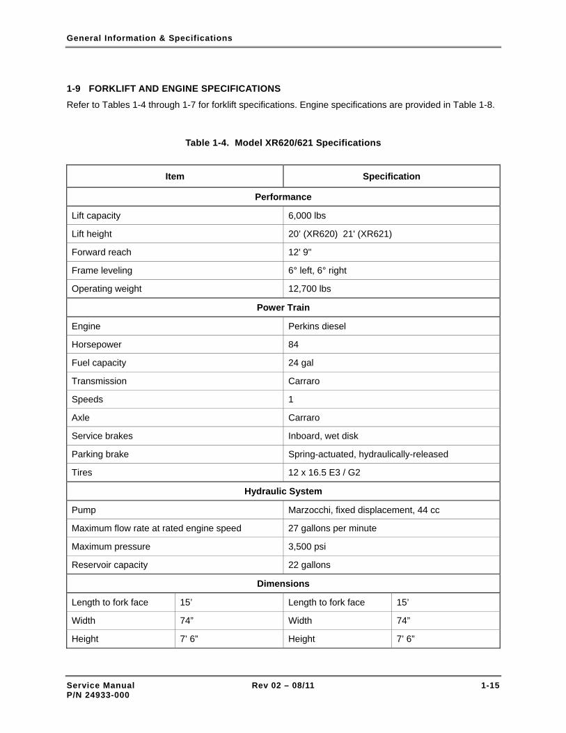
1-9 FORKLIFT AND ENGINE SPECIFICATIONS
Refer to Tables 1-4 through 1-7 for forklift specifications. Engine specifications are provided in Table 1-8.
Table 1-4. Model XR620/621 Specifications
Item Specification
Performance
Lift capacity 6,000 lbs
Lift height 20’ (XR620) 21' (XR621)
Forward reach 12' 9"
Frame leveling 6° left, 6° right
Operating weight 12,700 lbs
Power Train
Engine Perkins diesel
Horsepower 84
Fuel capacity 24 gal
Transmission Carraro
Speeds 1
Axle Carraro
Service brakes Inboard, wet disk
Parking brake Spring-actuated, hydraulically-released
Tires 12 x 16.5 E3 / G2
Hydraulic System
Pump Marzocchi, fixed displacement, 44 cc
Maximum flow rate at rated engine speed 27 gallons per minute
Maximum pressure 3,500 psi
Reservoir capacity 22 gallons
Dimensions
Length to fork face 15’ Length to fork face 15’
Width 74” Width 74”
Height 7’ 6” Height 7’ 6”
Service Manual Rev 02 – 08/11 1-15 P/N 24933-000

General Information & Specifications
Table 1-5. Model XR842 Specifications
Item Specification
Performance
Lift capacity 8,000 lbs
Lift height 41' 5"
Forward reach 28' 10"
Frame leveling 11° left, 11° right
Operating weight 26,850 lbs
Power Train
Engine Perkins diesel
Horsepower 99
Fuel capacity 48 gal
Transmission Dana
Speeds 3
Axle Dana/Spicer
Service brakes Inboard, wet disk
Parking brake Spring-actuated, hydraulically-released
Tires Foam filled, 13.0 x 24 E3 / G2
Hydraulic System
Pump Kawasaki, variable displacement axial piston 60 cc
Maximum flow rate at rated engine speed 39 gallons per minute
Maximum pressure 3,500 psi
Reservoir capacity 45 gallons
Dimensions
Length to fork face 20' 11" Wheel base 10'
Width 8' 5" Ground clearance 16.5"
Height 7' 11" Turning radius 12' (inside)
Service Manual Rev 02 – 08/11 1-16 P/N 24933-000

General Information & Specifications
Table 1-6. Model XR1045 Specifications
Item Specification
Performance
Lift capacity 10,000 lbs
Lift height 44' 8"
Forward reach 30' 4"
Frame leveling 11° left, 11° right
Operating weight 27,130 lbs
Power Train
Engine Perkins diesel
Horsepower 108
Fuel capacity 48 gallons
Transmission Carraro
Speeds 4
Axle Carraro
Service brakes Inboard, wet disk
Parking brake Spring-actuated, hydraulically-released
Tires Foam filled, 13.0 x 24 E3 / G2
Hydraulic System
Pump Kawasaki, variable displacement axial piston (80 cc)
Maximum flow rate at rated engine speed 49 gallons per minute
Maximum pressure 3,500 psi
Reservoir capacity 45 gallons
Dimensions
Length to fork face 21' 9" Wheel base 10'
Width 8' 5" Ground clearance 16.5"
Height 7' 11" Turning radius 12' (inside)
Service Manual Rev 02 – 08/11 1-17 P/N 24933-000

General Information & Specifications
Table 1-7. Model XR1245 Specifications
Item Specification
Performance
Lift capacity 12,000 lbs
Lift height 44' 8"
Forward reach 30' 4"
Frame leveling 11° left, 11° right
Operating weight 32,930 lbs
Power Train
Engine Perkins diesel
Horsepower 122
Fuel capacity 48 gal
Transmission Carraro
Speeds 4
Axle Carraro
Service brakes Inboard, wet disk
Parking brake Spring-actuated, hydraulically-released
Tires Foam filled, 15.5 x 25 E3 / G2
Hydraulic System
Pump Kawasaki, variable displacement axial piston 80 cc
Maximum flow rate at rated engine speed 49 gallons per minute
Maximum pressure 3,500 psi
Reservoir capacity 45 gallons
Dimensions
Length to fork face 22' 3" Wheel base 10' 4"
Width 8' 5" Ground clearance 16.5"
Height 7' 11" Turning radius 12' 2" (inside)
Service Manual Rev 02 – 08/11 1-18 P/N 24933-000

General Information & Specifications
Table 1-8. Model XR1255 Specifications
Item Specification
Performance
Lift capacity 12,000 lbs
Lift height 55’
Forward reach 38'
Frame leveling 11° left, 11° right
Operating weight 35,700 lbs
Power Train
Engine Perkins diesel
Horsepower 122
Fuel capacity 72 gallons
Transmission Carraro
Speeds 4
Axle Carraro
Service brakes Inboard, wet disk
Parking brake Spring-actuated, hydraulically-released
Tires Foam filled, 15.5 x 25 E3 / G2
Hydraulic System
Pump Kawasaki, variable displacement axial piston 80 cc
Maximum flow rate at rated engine speed 49 gallons per minute
Maximum pressure 3,500 psi
Reservoir capacity 45 gallons
Dimensions
Length to fork face 25' Wheel base 11' 9"
Width 8' 5" Ground clearance 16.5"
Height 7' 11" Turning radius 14' (inside)
Service Manual Rev 02 – 08/11 1-19 P/N 24933-000

General Information & Specifications
Table 1-9. Model XR1267 Specifications
Item Specification
Performance
Lift capacity 12,000 lbs
Lift height 67’
Forward reach 53' 8"
Frame leveling 8° left, 8° right
Operating weight 46,300 lbs
Power Train
Engine Perkins diesel
Horsepower 130
Fuel capacity 72 gallons
Transmission Dana
Speeds 3
Axle Dana/Spicer
Service brakes Inboard, wet disk
Parking brake Spring-actuated, hydraulically-released
Tires Foam filled, 17.5 x 25 E3 / G2
Hydraulic System
Pump Kawasaki, variable displacement axial piston (80 cc)
Maximum flow rate at rated engine speed 49 gallons per minute
Maximum pressure 4,000 psi
Reservoir capacity 58 gallons
Dimensions
Length to fork face 26' 6" Wheel base 147”
Width 102" Ground clearance 15"
Height 8' 11" Turning radius 15' 10” (inside)
Service Manual Rev 02 – 08/11 1-20 P/N 24933-000

General Information & Specifications
Table 1-10. Model XR1270 Specifications
Item Specification
Performance
Lift capacity 12,000 lbs
Lift height 69’ 10”
Forward reach 53’ 8”
Frame leveling 8° left, 8° right
Operating weight 47,300 lbs
Power Train
Engine Perkins diesel
Horsepower 130
Fuel capacity 72 gallons
Transmission Dana
Speeds 3
Axle Dana/Spicer
Service brakes Inboard, wet disk
Parking brake Spring-actuated, hydraulically-released
Tires Foam filled, 17.5 x 25 E3 / G2
Hydraulic System
Pump Kawasaki, variable displacement axial piston (80 cc)
Maximum flow rate at rated engine speed 49 gallons per minute
Maximum pressure 4,000 psi
Reservoir capacity 58 gallons
Dimensions
Length to fork face 26' 5" Wheel base 147”
Width 102" Ground clearance 15"
Height 8' 11" Turning radius 15' 10” (inside)
Service Manual Rev 02 – 08/11 1-21 P/N 24933-000

General Information & Specifications
Table 1-11. Model XR1534 Specifications
Item Specification
Performance
Lift capacity 15,000 lbs
Lift height 34'
Forward reach 17'
Frame leveling 11° left, 11° right
Operating weight 29,000 lbs
Power Train
Engine Perkins diesel
Horsepower 122
Fuel capacity 48 gal
Transmission Carraro
Speeds 4
Axle Carraro
Service brakes Inboard, wet disk
Parking brake Spring-actuated, hydraulically-released
Tires Foam filled, 15.5 x 25 E3 / G2
Hydraulic System
Pump Kawasaki, variable displacement axial piston 80 cc
Maximum flow rate at rated engine speed 49 gallons per minute
Maximum pressure 4,300 psi
Reservoir capacity 45 gallons
Dimensions
Length to fork face 21' 6" Wheel base 124"
Width 101" Ground clearance 16.5"
Height 7' 11" Turning radius 12' 2" (inside)
Service Manual Rev 02 – 08/11 1-22 P/N 24933-000

General Information & Specifications
Table 1-12. Model XR1642 Specifications
Item Specification
Performance
Lift capacity 16,000 lbs
Lift height 41’ 7”
Forward reach 24’ 7”
Frame leveling 8° left, 8° right
Operating weight 41,000 lbs
Power Train
Engine Perkins diesel
Horsepower 130
Fuel capacity 72 gallons
Transmission Dana
Speeds 3
Axle Dana/Spicer
Service brakes Inboard, wet disk
Parking brake Spring-actuated, hydraulically-released
Tires Foam filled, 17.5 x 25 E3 / G2
Hydraulic System
Pump Kawasaki, variable displacement axial piston (80 cc)
Maximum flow rate at rated engine speed 49 gallons per minute
Maximum pressure 4,000 psi
Reservoir capacity 58 gallons
Dimensions
Length to fork face 26’ 6” Wheel base 147”
Width 102” Ground clearance 15"
Height 8’ 11” Turning radius 15' 10” (inside)
Service Manual Rev 02 – 08/11 1-23 P/N 24933-000

General Information & Specifications
Table 1-13. Model XR2034 Specifications
Item Specification
Performance
Lift capacity 20,000 lbs
Lift height 34’
Forward reach 16’ 4”
Frame leveling 8° left, 8° right
Operating weight 40,140 lbs
Power Train
Engine Perkins diesel
Horsepower 130
Fuel capacity 72 gallons
Transmission Dana
Speeds 3
Axle Dana/Spicer
Service brakes Inboard, wet disk
Parking brake Spring-actuated, hydraulically-released
Tires Foam filled, 17.5 x 25 E3 / G2
Hydraulic System
Pump Kawasaki, variable displacement axial piston (80 cc)
Maximum flow rate at rated engine speed 49 gallons per minute
Maximum pressure 4,000 psi
Reservoir capacity 58 gallons
Dimensions
Length to fork face 21’ 7” Wheel base 147”
Width 102” Ground clearance 15"
Height 8’ 11” Turning radius 15' 10” (inside)
Service Manual Rev 02 – 08/11 1-24 P/N 24933-000

General Information & Specifications
Table 1-14. Model XR2045 Specifications
Item Specification
Performance
Lift capacity 20,000 lbs
Lift height 45’
Forward reach 27’ 2”
Frame leveling 8° left, 8° right
Operating weight 44,750 lbs
Power Train
Engine Perkins diesel
Horsepower 130
Fuel capacity 72 gallons
Transmission Dana
Speeds 3
Axle Dana/Spicer
Service brakes Inboard, wet disk
Parking brake Spring-actuated, hydraulically-released
Tires Foam filled, 17.5 x 25 E3 / G2
Hydraulic System
Pump Kawasaki, variable displacement axial piston (80 cc)
Maximum flow rate at rated engine speed 49 gallons per minute
Maximum pressure 4,000 psi
Reservoir capacity 58 gallons
Dimensions
Length to fork face 22’ 3” Wheel base 147”
Width 102” Ground clearance 15"
Height 8’ 11” Turning radius 15' 10” (inside)
Service Manual Rev 02 – 08/11 1-25 P/N 24933-000

General Information & Specifications
Table 1-15. Model XR2450 Specifications
Item Specification
Performance
Lift capacity 24,000 lbs
Lift height 50'
Forward reach 36'
Frame leveling 8° left, 8° right
Operating weight 52,500 lbs
Power Train
Engine Perkins diesel
Horsepower 130
Fuel capacity 72 gal
Transmission Dana
Speeds 3
Axle Kessler
Service brakes Inboard, wet disk
Parking brake Spring-actuated, hydraulically-released
Tires Foam filled, 16 x 25 E3 / G2
Hydraulic System
Pump Kawasaki, variable displacement axial piston 80 cc
Maximum flow rate at rated engine speed 49 gallons per minute
Maximum pressure 4,000 psi
Reservoir capacity 58 gallons
Dimensions
Length to fork face 27' Wheel base 148"
Width 102" Ground clearance 15"
Height 9' 6" Turning radius 16' 8" (inside)
Service Manual Rev 02 – 08/11 1-26 P/N 24933-000

General Information & Specifications
Table 1-16. Model XR3034 Specifications
Item Specification
Performance
Lift capacity 30,000 lbs
Lift height 34'
Forward reach 17' 6”
Frame leveling 8° left, 8° right
Operating weight 47,850 lbs
Power Train
Engine Perkins diesel
Horsepower 130
Fuel capacity 72 gal
Transmission Dana
Speeds 3
Axle Kessler
Service brakes Inboard, wet disk
Parking brake Spring-actuated, hydraulically-released
Tires Foam filled, 16 x 25 E3 / G2
Hydraulic System
Pump Kawasaki, variable displacement axial piston 80 cc
Maximum flow rate at rated engine speed 49 gallons per minute
Maximum pressure 4,500 psi
Reservoir capacity 58 gallons
Dimensions
Length to fork face 23' 4" Wheel base 148"
Width 102" Ground clearance 15"
Height 9' 6" Turning radius 16' 8" (inside)
Service Manual Rev 02 – 08/11 1-27 P/N 24933-000
General Information & Specifications
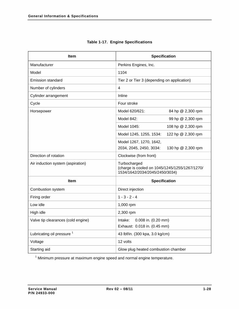
Table 1-17. Engine Specifications
Item Specification
Manufacturer Perkins Engines, Inc.
Model 1104
Emission standard Tier 2 or Tier 3 (depending on application)
Number of cylinders 4
Cylinder arrangement Inline
Cycle Four stroke
Model 620/621: 84 hp @ 2,300 rpm
Model 842: 99 hp @ 2,300 rpm
Model 1045: 108 hp @ 2,300 rpm
Model 1245, 1255, 1534: 122 hp @ 2,300 rpm
Horsepower
Model 1267, 1270, 1642, 2034, 2045, 2450, 3034: 130 hp @ 2,300 rpm
Direction of rotation Clockwise (from front)
Air induction system (aspiration) Turbocharged (charge is cooled on 1045/1245/1255/1267/1270/ 1534/1642/2034/2045/2450/3034)
Item Specification
Combustion system Direct injection
Firing order 1 - 3 - 2 - 4
Low idle 1,000 rpm
High idle 2,300 rpm
Valve tip clearances (cold engine) Intake: 0.008 in. (0.20 mm) Exhaust: 0.018 in. (0.45 mm)
Lubricating oil pressure 1 43 lbf/in. (300 kpa, 3.0 kg/cm)
Voltage 12 volts
Starting aid Glow plug heated combustion chamber
1 Minimum pressure at maximum engine speed and normal engine temperature.
Service Manual Rev 02 – 08/11 1-28 P/N 24933-000

General Information & Specifications
1-10 TORQUE WRENCH USE
Numerous forklift components require that the attaching hardware be torqued to a specific value during component installation. A torque wrench is required to tighten bolts, nuts, and screws. Listed below are standard procedures and precautions to observe when using a torque wrench:
• Ensure that the torque wrench has been calibrated.
• Always work with clean fastener threads that are free of corrosion.
• If an installation procedure specifies a thread lubricant, use it.
• Observe the torque sequence instructions provided in installation procedures.
• Pull the torque wrench in a clockwise direction, using a steady, smooth motion. A fast or jerky tightening motion will result in an improperly torqued fastener.
• Avoid over-tightening a fastener with a conventional wrench or impact wrench before applying a torque wrench to the fastener.
• Do not use the torque wrench to apply greater amounts of torque than its rated capacity.
• Never use a torque wrench as a hammer or to pry apart parts.
• Never use a torque wrench as a conventional wrench.
• Do not apply a torque wrench to a nut that has been tightened. Back off the nut one turn with a conventional wrench and retighten it to the correct torque with a torque wrench.
• Do not use the torque wrench to break loose bolts that have been previously tightened.
• Avoid dropping a torque wrench. If a wrench is dropped, check its accuracy on a torque tester.
• When using a torque wrench, do not over-torque the fastener by applying torque past the release point. Learn the feel of the torque wrench release rather than relying on the sound the wrench makes.
• When not in use, set the torque wrench to its lowest torque value. But DO NOT set the wrench to a value below the lowest torque value.
When the torque wrench is in frequent or continuous use, periodically check the wrench's calibration accuracy.
1-11 CAP SCREW TORQUE VALUES
Refer to Table 1-9 for a listing of recommended assembly torque values for Society of Automotive Engineers (SAE) Grade 5 and Grade 8 caps crews. The following criteria apply to the determination of torque values:
• All torque values are based on the use of through-hardened flat washers under the bolt head and nut or only under the bolt head in a tapped hole application. This provides a uniform, hard, smooth bearing surface.
• Torque values are calculated at 75% of proof load. This calculation method provides a safety factor.
• All dry torque values are given for the as received condition, such as plated hex head cap screws.
Ensure that damaged cap screws are replaced with SAE grade 8 cap screws from a reputable manufacturer/vendor. Refer to Figure 1-9 for a diagram depicting the cap screw head markings of a grade 8 cap screw or bolt.
Service Manual Rev 02 – 08/11 1-29 P/N 24933-000

General Information & Specifications
Table 1-18. Tightening Torque Values – Cap Screws
Tightening Torque (Ft-Lbs) Nominal Diameter (Inches) and Threads-Per-Inch SAE Grade 5 Cap Screws SAE Grade 8 Cap Screws
1/4 20 8 (96) a 12 (144) a
1/4 28 10 (120) a 14 (170) a
5/16 18 17 (205) a 25 (300) a
5/16 24 19 (230) a 27 (325) a
3/8 16 31 (370) a 44 (530) a
3/8 24 35 (420) a 49 (590) a
7/16 14 49 (590) a 70
7/16 20 56 (670) a 78
1/2 13 76 108
1/2 20 86 120
9/16 12 110 154
9/16 18 122 172
5/8 11 150 212
5/8 18 170 240
3/4 10 265 375
3/4 16 295 420
7/8 9 430 606
7/8 14 475 674
1 8 645 909
1 14 723 1020
1-1/8 7 794 1287
1-1/8 12 890 1444
1-1/4 7 1120 1817
1-1/4 12 1241 2013
1-3/8 6 1469 2382
1-3/8 12 1672 2712
Service Manual Rev 02 – 08/11 1-30 P/N 24933-000

General Information & Specifications
Table 1-18. Tightening Torque Values – Cap Screws
Tightening Torque (Ft-Lbs) Nominal Diameter (Inches) and Threads-Per-Inch SAE Grade 5 Cap Screws SAE Grade 8 Cap Screws
1-1/2 6 1949 3161
1-1/2 12 2194 3557
a Installation with an inch-pound torque wrench is recommended. The inch-pound torque value is listed in parentheses.
SAE GRADE 8BOLT MARKINGS
Figure 1-9. SAE Grade 8 Bolt Markings
Service Manual Rev 02 – 08/11 1-31 P/N 24933-000

General Information & Specifications
Service Manual Rev 02 – 08/11 1-32 P/N 24933-000
THIS PAGE INTENTIONALLY LEFT BLANK

Maintenance & Operation Safety
Section 2
Maintenance & Operation Safety
2-1 GENERAL Operating and maintaining a rough-terrain, forward-reach forklift can be a very safe endeavor, or a very dangerous endeavor. The U.S. Government, private industry, and Xtreme Manufacturing have extended a great deal of time, effort, and money in making the operator’s and mechanic’s workplace safe. To help accomplish that goal, standardized safety signal words and symbols have been developed and incorporated in this manual.
2-2 SAFETY SIGNAL WORDS Safety signal words are the word or words that call attention to a hazard and designate a degree or level of hazard seriousness. The signal words used in this manual are DANGER, WARNING, and CAUTION.
The word DANGER in a red box indicates an imminently hazardous situation which, if not avoided, will result in death or serious injury.
The word WARNING in an orange box indicates a potentially hazardous situation which, if not avoided, could result in death or serious injury.
The word CAUTION in a yellow box, when used with the safety alert symbol, indicates a potentially hazardous situation which, if not avoided, could result in minor or moderate injury.
The word CAUTION in a yellow box, when used without the safety alert symbol, indicates a potentially hazardous situation which, if not avoided, may result in property damage.
2-3 NOTES Notes are used to highlight important maintenance information that is provided to facilitate troubleshooting and repair actions. Notes are not used to convey any type of danger or safety information. Notes may appear before or after the affected text or illustration and appear as follows:
NOTE: Do not over-tighten the chain.
Service Manual Rev 02 – 08/11 2-1 P/N 24933-000

Maintenance & Operation Safety
2-4 SAFETY SYMBOLS
Safety symbols are used in the manual to warn of hazardous situations. Xtreme Manufacturing provides these symbols in an attempt to inform all mechanics and operators, regardless of reading and language skills, of as many potential hazards as possible. These symbols cover many, but not all, potential dangers and hazards associated with operating the forklift. Make safety a high priority while operating the forklift. Learn and follow all safety messages in this manual and on the forklift labels to prevent death, injury, or equipment damage. Refer to Table 2-1 for a complete listing of safety symbols and their meaning.
Table 2-1. Safety Symbols
Symbol Meaning Symbol Meaning
GENERAL SAFETY ALERT SYMBOL
DO NOT OPERATE!
VEHICLE DOWN FOR SAFETY OR
MAINTENANCE
PERSONAL PROTECTIVE EQUIPMENT
WEAR EAR PROTECTION
PERSONAL PROTECTIVE EQUIPMENT
WEAR SAFETY GLASSES
PERSONAL PROTECTIVE EQUIPMENT
WEAR HARD HAT
PERSONAL PROTECTIVE EQUIPMENT
WEAR SAFETY GLOVES
PERSONAL PROTECTIVE EQUIPMENT
WEAR SAFETY BOOTS
PERFORM OPERATOR INSPECTION BEFORE
STARTING THIS VEHICLE
KNOW FIRST AID INSTRUCTIONS AND/OR
FIRST AID LOCATIONS ON JOBSITE
READ MAINTENANCE MANUAL BEFORE
WORKING ON THIS VEHICLE
READ THE OPERATOR MANUAL BEFORE
OPERATING THIS VEHICLE
READ MATERIAL SAFETY DATA SHEETS (MSDS) FOR CHEMICALS AND
FLUIDS
Service Manual Rev 02 – 08/11 2-2 P/N 24933-000

Maintenance & Operation Safety
Table 2-1. Safety Symbols – Cont.
Symbol Meaning Symbol Meaning
WARNING!
HOT SURFACE. KEEP HANDS AWAY
WARNING!
HOT OIL. DO NOT OPEN UNLESS CAP IS COOL TO
TOUCH.
WARNING!
USE BOARD OR CARDBOARD TO CHECK FOR HYDRAULIC LEAKS. DO NOT USE YOUR HAND
WARNING!
HYDRAULIC OIL UNDER PRESSURE
HYDRAULIC SYSTEM UNDER PRESSURE
ATTACH DANGER TAG
WARNING!
KEEP HANDS A SAFE DISTANCE FROM ROTATING BELTS
WARNING!
ROTATING FAN BLADES CAN CUT
WARNING!
KEEP HANDS A SAFE DISTANCE FROM
ROTATING FAN BLADES
WARNING!
ROTATING BELTS CAN CUT OR ENTANGLE
KEEP FLAMES AND IGNITION SOURCES AWAY
NO SMOKING
KEEP LIT CIGARETTES AWAY
PINCH POINT FOR HANDS
PINCH POINTS FOR BODY
Service Manual Rev 02 – 08/11 2-3 P/N 24933-000

Maintenance & Operation Safety
Table 2-1. Safety Symbols – Cont.
Symbol Meaning Symbol Meaning
LEAD-ACID BATTERIES DEVELOP EXPLOSIVE
GASES
BATTERY
WARNING!
EXPLOSION HAZARD
HAVE ADEQUATE VENTILATION IF
OPERATING THIS VEHICLE IN AN ENCLOSED SPACE
MAKE SURE ALL SAFETY LABELS ARE ATTACHED
AND LEGIBLE
REPLACE WORN AND ILLEGIBLE SAFETY
LABELS AND LABELS
DO NOT USE ETHER AS A STARTING FLUID
DO NOT OPERATE IF USING ALCOHOL, DRUGS,
OR MEDICATION
USE 3-POINT CONTACT MOUNTING AND
DISMOUNTING FORKLIFT
DO NOT JUMP WHILE DISMOUNTING FORKLIFT
FASTEN SEAT BELT
DO NOT USE AS A PERSONNEL CARRIER
DO NOT ALLOW RIDERS ON FORKLIFT FRAME OR
FENDERS
DO NOT ALLOW RIDERS ON OR IN OPERATOR CAB
Service Manual Rev 02 – 08/11 2-4 P/N 24933-000

Maintenance & Operation Safety
Table 2-1. Safety Symbols – Cont.
Symbol Meaning Symbol Meaning
FALLING OFF OF ATTACHMENT CAN
RESULT IN DEATH OR SERIOUS INJURY
SET PARKING BRAKE TO ON
ENGAGE PARKING BREAK
SET PARKING BRAKE TO OFF
DISENGAGE PARKING BRAKE
WARNING!
VEHICLE ROLL AWAY CAN CAUSE DEATH OR SERIOUS INJURY
WARNING!
VEHICLE TIP OVER CAN CAUSE DEATH OR SERIOUS INJURY
DO NOT JUMP! IF VEHICLE TIPS, KEEP
SEAT BELT ON AND BRACE YOURSELF
DO NOT TRAVEL WITH BOOM RAISED
DO NOT RAISE BOOM WHILE TRAVELING ON A
SLOPE
TIP OVER HAZARD, ESPECIALLY TRAVELING UP A SLOPE WITHOUT A
LOAD
WARNING
ELECTROCUTION CAN CAUSE DEATH OR SERIOUS INJURY
DANGER!
KEEP A SAFE DISTANCE FROM ELECTRICAL LINES
DO NOT ALLOW ANYONE UNDER A RAISED LOAD
Service Manual Rev 02 – 08/11 2-5 P/N 24933-000

Maintenance & Operation Safety
2-5 LOCKOUT/TAGOUT PROCEDURE
Perform the following procedure to lockout and tagout the forklift. This procedure, requiring a lock, danger tags, and a condition tag is to be used whenever the forklift is unsafe for operation or maintenance.
REMOVING FORKLIFT FROM SERVICE
1. Attach danger tags (Figure 2-1) to steering wheel and ignition key.
2. Pull back on both battery cover T-handles until they release from holders (Figure 1-2).
3. Lower battery cover.
4. Set battery disconnect switch (Figure 2-2) to OFF.
5. Lock battery disconnect switch.
If forklift is unsafe for operation or maintenance, the defect or defects must be clearly documented and posted in a conspicuous place on the forklift. Failure to comply may result in death, serious injury, and property damage.
6. Attach condition tag (Figure 2-1) to battery disconnect switch. Condition tag should clearly state why forklift is unsafe for operation or maintenance.
RETURNING FORKLIFT TO SERVICE
When the forklift has been repaired and made safe for operation and maintenance, perform the following procedure to return the forklift to service:
1. Remove lock and condition tag from battery disconnect switch.
2. Raise and secure battery cover.
3. Remove danger tags from steering wheel and ignition key.
NOTE: SAMPLE DANGER TAGS ARE PROVIDED IN THE APPENDIX, MAINTENANCE FORMS & SAFETY TAGS.
Figure 2-1. Danger and Condition Tags
Service Manual Rev 02 – 08/11 2-6 P/N 24933-000

Maintenance & Operation Safety
Figure 2-2. Battery Disconnect Switch
2-6 GENERAL MAINTENANCE PRECAUTIONS
• Do not make adjustments that you do not understand.
• Do not permit loose clothing or long hair near moving parts.
• Use extreme care if emergency repairs must be made in adverse conditions.
• Do not wear clothing which is contaminated by lubricating oil. Do not put material which is contaminated with oil into the pockets of clothing.
2-7 VITON SEALS
Viton is used by many manufacturers and is a safe material under normal conditions of operation. Some seals used in the engine and in components fitted to the engine are made of Viton.
If Viton is burned, a product of this burnt material is an acid which is extremely dangerous. Never allow this burnt material to come into contact with the skin or with the eyes. If it is
Service Manual Rev 02 – 08/11 2-7 P/N 24933-000

Maintenance & Operation Safety
necessary to come into contact with components which have been burnt, ensure that the precautions which follow are used:
• Ensure that the components have cooled.
• Use neoprene gloves and discard the gloves safely after use.
• Wash the area with calcium hydroxide solution and then with clean water.
• Disposal of components and gloves which are contaminated must be in accordance with local regulations.
If there is contamination of the skin or eyes, wash the affected area with a continuous supply of clean water or with calcium hydroxide solution for 15-60 minutes. Obtain immediate medical attention.
2-8 USING COMPRESSED AIR SAFELY
• Always wear goggles, face shield, or other eye protection when using compressed air to clean equipment.
• Do not allow compressed air to contact your skin. If compressed air enters your skin, obtain medical help immediately.
• Do not use compressed air to clean dust and dirt from clothing.
• Ensure that the nozzle is equipped with a chip guard.
• Never use compressed air that exceeds 30 psi.
• Hoses should not be strung across floors or aisles where they are liable to cause a trip hazard. When possible, air supply hoses should be suspended overhead.
• Hose ends must be secured to prevent whipping if an accidental cut or break occurs.
• Never point pneumatic tools at a person.
• Do not use compressed air to dry roller bearings. The air can cause the bearing to rotate at an extremely high speed and disintegrate.
• Turn off the air supply before disconnecting a pneumatic tool (unless equipped with a quick-disconnect coupling).
2-9 BATTERY HANDLING AND MAINTENANCE
• If contact with battery acid occurs, administer the following first aid treatment to self or others: – External contact – Flush with water.
Service Manual Rev 02 – 08/11 2-8 P/N 24933-000

Maintenance & Operation Safety
– Eyes – Flush with water for at least 15 minutes. Get medical attention immediately.
– Internal contact – Drink large quantities of water. Follow with Milk of Magnesia, beaten egg, or vegetable oil. Get medical attention immediately.
– IMPORTANT – In case of internal contact, DO NOT give fluids that induce vomiting.
• Disconnect the battery terminals before a repair is made to the electrical system.
• Lead-acid batteries produce flammable and potentially explosive gases. To avoid injury or death when checking, testing, or charging batteries: – DO NOT use smoking materials near batteries. – Keep arcs, sparks, and open flames away from batteries. – Provide ventilation for flammable vapors. – Wear proper personal protective equipment, including safety glasses.
• Fluid in electric storage batteries contains sulfuric acid which is a poison that can cause severe chemical burns. Avoid all contact of fluid with eyes, skin, or clothing. Use protective gear when handling batteries.
• DO NOT tip a battery beyond a 45° angle in any direction. • Wear eye protection when starting a forklift with jump start cables. Improper
jump start procedures can cause the battery to explode. • Do not allow sparks or fire near the batteries (especially when the batteries are
on charge) because the gases from the electrolyte are highly flammable. The battery fluid is dangerous to the skin and especially to the eyes.
• NEVER jump start a frozen battery, as it can explode. Let the battery thaw out before charging.
• NEVER jump start the forklift directly at the starter solenoid. This could cause the forklift to lurch forward or backward, resulting in injury or death.
• To avoid injury or death when jump starting with another vehicle, ensure the two vehicles are not touching.
• DO NOT allow jump start cable ends to contact each other near the battery.
• Connect charged battery positive (+) to stalled battery positive (+).
• Connect charged battery negative (–) to stalled forklift ground. Make the connection to the stalled vehicle ground LAST.
• Connect jump start cable to stalled forklift ground a safe distance from the battery to PREVENT sparks near the battery.
• Jump start only with a power source with the same voltage as the stalled forklift.
• Jump start power source must have a negative-ground electrical system.
• To safely carry the current load, jump start cables must be fabricated from 2 AWG cable or larger.
• Electrolyte is an acid and cause injury if it contacts the skin or eyes.
Service Manual Rev 02 – 08/11 2-9 P/N 24933-000

Maintenance & Operation Safety
2-10 ENGINE OPERATION AND MAINTENANCE
• Do not add lubricating oil to the engine when it is running.
• Do not make adjustments to the engine while it is running unless you have been correctly trained to make the adjustments. Use extreme care to prevent injury.
• Do not operate the engine if a safety guard has been removed.
• Do not remove the filler cap or any component of the cooling system while the engine is hot and while the coolant is under pressure. Dangerous hot coolant can be discharged and cause severe burns.
• Ensure that the engine does not run in a location where it can cause a concentration of toxic emissions.
• Operate the engine only when seated in the forklift operator's seat.
• Keep away from moving parts during engine operation.
• Only one person must control the engine.
• Other persons must be kept at a safe distance while the engine is operating.
• Some moving parts cannot be seen clearly while the engine runs. Exercise extreme caution when placing head, hands, and arms in the engine compartment.
• The combustible material of some components of the engine (for example certain seals) can become extremely dangerous when burned. Never allow this burnt material to come into contact with the skin or eyes.
• Turbochargers operate at high speed and at high temperatures. Keep fingers, tools, and debris away from the inlet and outlet ports of the turbocharger and prevent contact with hot surfaces.
• Do not wash an engine when it is running or is hot. If cold cleaning fluids are applied to a hot engine, certain components on the engine could be damaged.
• Use only genuine Perkins Engines Inc. parts. Using substitute parts can damage the engine and may void the warranty. Contact Perkins at 1-888-PERK-ENG or www.perkins.com.
Service Manual Rev 02 – 08/11 2-10 P/N 24933-000

Maintenance & Operation Safety
2-11 FUEL HANDLING AND MAINTENANCE
• Always clean spilled fuel. Material which has been contaminated by fuel must be moved to a safe place.
• Diesel fuel can damage the skin of certain persons. Protect your hands with gloves or a special solution to protect the skin.
• Do not put fuel in the tank while the engine is running (unless it is absolutely necessary).
• Do not smoke when you put fuel in the tank.
• Ensure that the IGNITION switch is in the OFF position before servicing or repairs are made to the fuel system. Fuel will be pumped out if the fuel lift pump has power applied.
• If your skin comes into contact with high-pressure fuel, obtain medical assistance immediately.
2-12 CALIFORNIA PROPOSITION 65 WARNINGS
• Engine exhaust from the forklift contains chemicals known to the State of California to cause cancer, birth defects, and other reproductive harm.
• Battery posts, terminals, and related accessories contain lead and lead compounds. These chemicals are known to the State of California to cause cancer, birth defects, and other reproductive harm.
• Discard used lubricating oil in accordance with local regulations to prevent environmental contamination.
2-13 FUNCTIONAL TESTS
Service Manual Rev 02 – 08/11 2-11 P/N 24933-000

Maintenance & Operation Safety
• Perform a pre-operation inspection and functional tests at the beginning of each work shift. Perform the pre-operation inspection of the forklift first. DO NOT perform the pre-operation inspection with the engine running or hot. Contact with moving or heated parts can cause injury or death.
• Perform the pre-operation inspection and functional tests in an open area. Inspections and functional tests may require assistance. Keep the assistant visible and a safe distance from the forklift to prevent injury or death.
• Remove forklift from service and comply with the lockout/tagout procedure (para. 2-5) if anything is found to be in need of repair or maintenance, or is defective, or is unsafe in any way.
The safety, efficiency, and service life of your forklift will be increased by performing functional tests at the beginning of each shift. If any of the items in the functional tests are not operating properly or within set tolerances, stop the forklift, follow proper shut-down procedures, tag the vehicle with “DO NOT OPERATE” tags, and have a qualified mechanic service or repair the forklift BEFORE placing it into service again.
2-14 SAFE OPERATION CHECKLIST
Wear the seat belts at all times.
Adjust the seat for optimum reach and comfort.
Adjust the mirrors to provide optimum visibility. Clean mirrors if dirty.
Wear all required personal protective equipment.
Operate the forklift only while securely seated in the operator's seat.
Never allow riders on the forklift.
Clear all people and obstacles from the work area.
Keep clear of overhead power lines.
Allow a proper warm-up time and wait for the gauges to register properly.
Verify the operation of all controls and functions.
Position the forklift to allow good visibility of the work area.
Service Manual Rev 02 – 08/11 2-12 P/N 24933-000

Maintenance & Operation Safety
Never use the boom or any attachment as a personnel carrier.
Position the boom and load as low as possible to maintain maximum stability.
Know the forklift's operating capabilities and limitations.
Know the hand signals used in the work area.
Ground the boom and engage the parking brake before leaving the forklift.
SHUT DOWN THE FORKLIFT WHEN:
Leaving the forklift.
The forklift is not operating properly.
The Hydraulic Oil Temperature indicator has been illuminated for longer than five (5) minutes. See note below.
The Low Brake Pressure indicator illuminates.
The Volts gauge indicates below 11 volts or above 15 volts.
The engine Oil pressure gauge indicates below 40 psi or above 80 psi when the engine is at normal operating temperature.
The engine Coolant temperature gauge indicates below 180°F or above 220°F when the engine is at normal operating temperature.
NOTE: When light comes on, stop and idle the engine to allow time for cooling. If light does not go out after five minutes, shut the forklift down. Attach DO NOT OPERATE tags to steering wheel and ignition key. Repair forklift before placing it into service again.
2-15 FUNCTIONAL TEST CHECKLIST
Operate the Boom Control forward and backward to raise and lower boom.
Operate the Boom Control left and right to extend and retract boom.
Press the Attachment Tilt switch up and down to tilt the boom attachment up and down. Note: Earlier forklift models are equipped with a combined Attachment Tilt and Frame Sway Control.
Operate the Frame Sway Control left and right to sway the frame left and right. Note: Earlier forklift models are equipped with a combined Attachment Tilt and Frame Sway Control.
Operate the Auxiliary Attachment Control (if a hydraulic attachment is being used).
Set the Lights switch to ON and OFF to check operation of the work lights.
Press the Horn button to sound horn.
Place the Travel Select lever in reverse to sound the backup alarm.
Operate the forklift in forward and reverse.
Test the Gear Select lever while operating the forklift in forward and reverse.
Test the service and parking brakes.
Service Manual Rev 02 – 08/11 2-13 P/N 24933-000

Maintenance & Operation Safety
– Depress the Service Brake pedal after the forklift begins to move. The forklift should stop immediately.
– Set the Parking Brake switch to ON. The forklift should not move unless the Parking Brake switch is set to OFF.
Test each steering function. Operate the forklift in forward and reverse at low idle speed and turn the steering wheel approximately ¼ turn in each direction.
– Align the wheels and set the steering select switch to crab steering.
– Align the wheels and set the Steering Select switch to 2 wheel (2W) steering.
– Align the wheels and set the Steering Select switch to 4 wheel (4W) steering.
Check gauges after the engine warms to the proper operating range.
Check the Volts gauge. The voltage gauge should read between 11 to 15 Volts.
Check the Coolant temperature gauge. The engine coolant temperature gauge should read between 180 to 200°F.
Check the Oil pressure gauge. The engine oil pressure gauge should read between 40 to 80 psi.
Check the Fuel gauge and make sure the fuel gauge reads between ½ to full. Fill the fuel tank if the Fuel gauge shows less than ½ full.
2-16 LOAD HANDLING
• Injury or death by electrocution can result from contact with or inadequate clearance with energized power lines or apparatus.
• NEVER operate the forklift in an area where active overhead power lines, overhead or underground cables, or other power sources exist.
• Contact the appropriate power or utility company to de-energize power lines or take other suitable precautions.
• Keep the forklift, attachments, and loads a safe distance from electrical power lines.
• Stay clear of power lines. Contact with power lines will cause death or severe injury. DO NOT allow forklift or load within 10 feet (3 meters) plus 2 times the line insulator length of any power line. Notify the power company to de-energize the power lines before operating the forklift near the power lines.
• Worksite operating directives and/or local or state codes might require a greater distance.
• Know the maximum height and reach of this reach forklift.
Service Manual Rev 02 – 08/11 2-14 P/N 24933-000

Maintenance & Operation Safety
• Failure to follow proper safety procedures when lifting, lowering, and traveling with a load can cause property damage, injury, or death.
• DO NOT exceed forklift capacity. The total rated capacity of the forks being used must equal or exceed forklift capacity. Forks can break or bend causing loss of load and possible injury or death.
• DO NOT exceed the manufacturer’s rated load for any auxiliary attachment. Any attempt to lift or carry loads in excess of the manufacturer’s rated load may cause forklift tip over, loss of load, or structural damage which could result in injury or death.
• Failure to keep personnel clear of the load area while the load is being raised or lowered can result in injury or death. DO NOT lift, swing, or move a load over anyone or over a forklift cab.
• Review the rated load capacity of each auxiliary attachment before performing any operation.
• Use the correct load chart and NEVER exceed the maximum load height and reach for the load weight.
• DO NOT exceed the manufacturer’s recommended load capacity.
• DO NOT operate the forklift with an unsafe load distribution.
• Adjust the load as necessary, especially for nonstandard loads.
• Use caution when handling loose material that can fall into the cab.
• Remove overhanging load materials, when possible, and watch for sliding material.
• DO NOT reach a load over posts or other objects that can enter the cab, if tipped.
Service Manual Rev 02 – 08/11 2-15 P/N 24933-000

Maintenance & Operation Safety
• Avoid sudden stops, starts, or turns. • Avoid carrying a swinging load. If necessary, secure the load by attaching it to
the forklift tie-downs and/or have another person assist with safely steadying the load.
2-17 PICKING UP A LOAD Perform the following procedure to pick up a load with the forklift:
1. Use correct load chart to review rated load capacity of auxiliary attachment being used. NEVER exceed specified weights and load centers.
2. Approach load slowly and squarely with fork tips straight and level. 3. Adjust spacing of the forks so they engage pallet or load at its maximum width. NEVER use just one
fork to lift load. 4. Tilt attachment forward so forks hang freely on fork shaft. 5. Insert forks under load until load is against fork frame. 6. Tilt forks back slightly to secure load.
2-18 CARRYING A LOAD Perform the following procedure to carry a load with the forklift:
1. Carry the load as low as possible while maintaining good ground clearance and visibility.
2. Back away slowly.
3. To travel with a load use first gear (1) for highest torque and pulling power. NEVER travel in third (3) or fourth gear (4) when carrying a load.
2-19 PLACING A LOAD Perform the following procedure to place a load with the forklift:
1. Before placing load, use appropriate load capacity chart to determine safe boom extension range.
2. Set parking brake switch to ON (engaged).
3. Set Declutch switch to ON.
Use of frame sway control with boom raised above horizontal can cause tip over resulting in injury or death. Always use frame sway control to level forklift BEFORE raising boom above horizontal. If forklift cannot be leveled using frame sway control, do not attempt to raise or place load. Reposition forklift or have surface leveled.
Service Manual Rev 02 – 08/11 2-16 P/N 24933-000

Maintenance & Operation Safety
4. Use frame sway control to level forklift.
5. Align the forks at the level the load is to be placed.
6. Extend boom slowly until load is just above area where it is to be placed.
7. Lower boom until pallet rests in position and forks are free to retract.
8. Retract forks slowly from under load.
2-20 LOAD SHIFT
If load shifts, take action immediately:
1. Stop forklift immediately.
2. Lower and adjust load to center its weight.
3. If load shift is too great for adjustment, rearrange load before attempting to move forklift.
2-21 PROPER USE OF FORKS
Adherence to the following guidelines will help ensure safe and reliable forklift operation:
• Inspect forks regularly and record the results. A fork inspection log suitable for copying is included in Appendix, Maintenance Forms and Safety Tags.
• Ensure capacity of forks meet or exceed forklift rating and load weight.
• Obtain written approval from the fork manufacturer prior to making any fork modifications.
• Determine the fork wear cycle and replacement schedule for your operation. Use of larger forks in demanding applications will extend fork life.
2-22 PROHIBITED PRACTICES
The following forklift practices are prohibited:
• DO NOT overload forks beyond the rated capacity.
• DO NOT change fork from one lift truck to another without knowing capacities of each.
• DO NOT use fork in an application for which it is not designed.
• DO NOT add a fork extension longer than 150% of the supporting fork’s length.
• DO NOT repair or modify forks in the field, especially by welding. Improper welding destroys heat treatment properties and makes the forks brittle.
• DO NOT carry full or partial loads on one fork.
• DO NOT apply sideways pressure to forks, commonly called side loading. Forks are designed for vertical loading only.
Service Manual Rev 02 – 08/11 2-17 P/N 24933-000

Maintenance & Operation Safety
2-23 OPERATOR HAND SIGNALS
It is extremely important that the forklift operator and signalman be able communicate clearly in a noisy environment. Operator hand signals (Figure 2-3) provide a means for communicating in this type of environment, but it is essential that the signals are understood by the operator and signalman. When signals for auxiliary equipment functions or conditions are required, they must be agreed upon in advance. When it necessary to give verbal instructions to the forklift operator, all forklift operation must first be stopped.
Figure 2-3. Operator Hand Signals
Service Manual Rev 02 – 08/11 2-18 P/N 24933-000
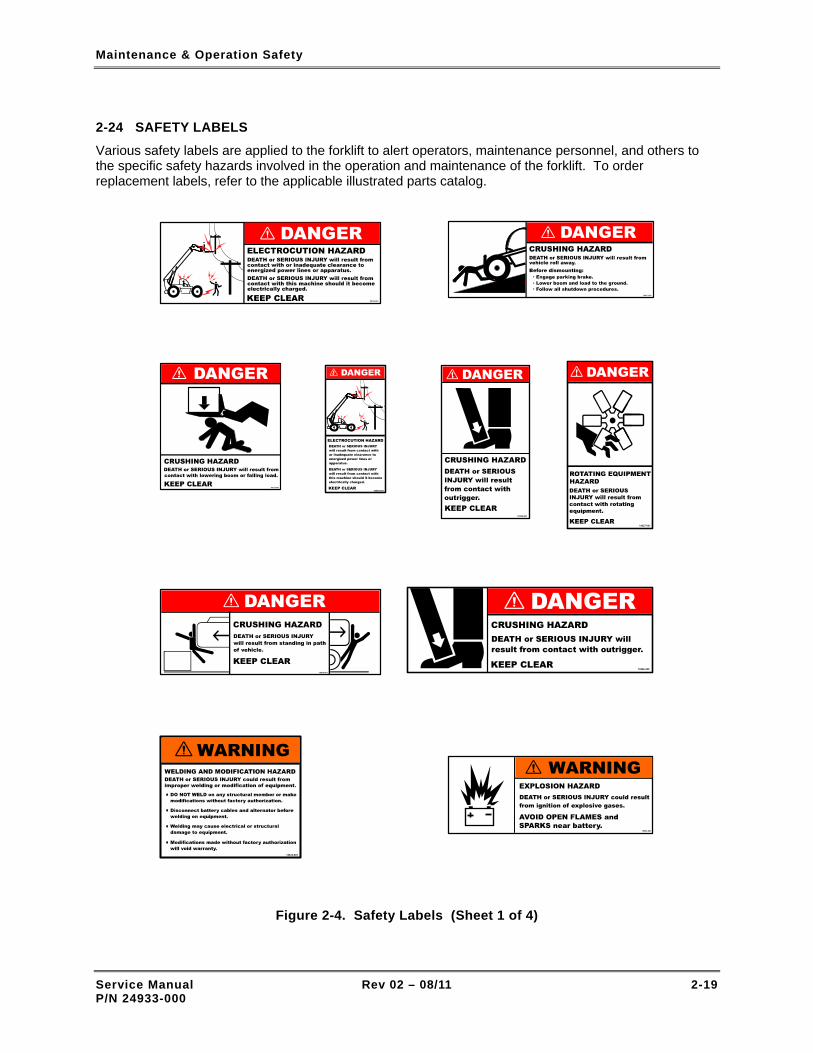
Maintenance & Operation Safety
2-24 SAFETY LABELS
Various safety labels are applied to the forklift to alert operators, maintenance personnel, and others to the specific safety hazards involved in the operation and maintenance of the forklift. To order replacement labels, refer to the applicable illustrated parts catalog.
Figure 2-4. Safety Labels (Sheet 1 of 4)
Service Manual Rev 02 – 08/11 2-19 P/N 24933-000

Maintenance & Operation Safety
WARNING
Figure 2-4. Safety Labels (Sheet 2 of 4)
Service Manual Rev 02 – 08/11 2-20 P/N 24933-000

Maintenance & Operation Safety
18332-000
DEATH or SERIOUS INJURY could result fromimproper operation when using tow connection.
DO NOT EXCEED RATED TOW CAPACITY.Max vertical load 500 LBS.Max tow capacity 5000 LBS.
DO NOT ELEVATE BOOM ABOVE 30 WHENTOWING.
Figure 2-4. Safety Labels (Sheet 3 of 4)
Service Manual Rev 02 – 08/11 2-21 P/N 24933-000

Maintenance & Operation Safety
DAMAGE may result from adjusting forkswhen carriage is loaded.
CARRIAGE DAMAGE
ONLY ADJUST FORKS WHEN CARRIAGEIS UNLOADED.
18331-000
Figure 2-4. Safety Labels (Sheet 4 of 4)
Service Manual Rev 02 – 08/11 2-22 P/N 24933-000

Maintenance Schedule
Section 3
Maintenance Schedule
3-1 ESTABLISHING A PREVENTIVE MAINTENANCE PROGRAM
An hourmeter (Figure 3-1) is installed in the operator control panel. The hourmeter displays elapsed engine operating hours and has a total readout of 9,999.9 hours. Use the hourmeter and the tables contained in this chapter to establish a comprehensive preventive maintenance program for the forklift. The same preventive maintenance tables are included in the Appendix, Maintenance Forms and Safety Tags, for the purpose of copying and reuse.
Refer to Tables 3-1 through 3-9 for specific maintenance requirements, intervals, and a reference to the specific paragraph in this Owner's Service Manual that provides the maintenance instructions for the task.
Figure 3-1. Forklift Hourmeter
Table 3-1. Preventive Maintenance – After First 50 Hours of Operation
Maintenance Requirement Refer to Para.
Change engine oil 5-8
Replace engine oil filters 5-9
Check air filter. Replace if necessary. 5-14
Replace fuel filter 5-10
Check engine hoses and connections for leaks, damage, and tightness 5-17
Check radiator hoses for leaks, damage, and tightness 5-18
Check engine electrical cables, leads, and connections for damage and tightness 5-19
Check for oil and coolant leaks 5-4
Check condition and tension of drive belts. Use tensiometer to check belt tension. 5-15
Lubricate front and rear driveshaft grease fittings 6-4
Service Manual Rev 02 – 08/11 3-1 P/N 24933-000

Maintenance Schedule
Table 3-1. Preventive Maintenance – After First 50 Hours of Operation – Cont.
Maintenance Requirement Refer to Para.
Change differential oil 6-6
Change wheel-end oil 6-8
Check wheel lug nuts torqued to 380-420 ft-lbs 7-2
Lubricate boom pivot point grease fittings 10-3
Lubricate front and rear axle cylinder pivot point grease fittings 4-3
Lubricate left and right outrigger pivot point grease fittings (XR1245/1255/1267/1270/2045/2450/3034) 4-3
Lubricate boom roller grease fittings and chains 10-3, 10-4
Replace hydraulic return line filter 8-12
Replace transmission filter and top off fluid 6-5
Table 3-2. Preventive Maintenance – After First 250 Hours of Operation
Maintenance Requirement Refer to Para.
Change transmission fluid (XR1045/1245/1255/1534) 6-5
Replace transmission filters (XR1045/1245/1255/1534) 6-5
Service Manual Rev 02 – 08/11 3-2 P/N 24933-000

Maintenance Schedule
Table 3-3. Preventive Maintenance – After Every 8 Hours of Operation
Maintenance Requirement Refer to Para.
Check engine oil level 5-2
Check engine coolant level 5-3
Check engine for oil and coolant leaks 5-4
Check for water in fuel-water separator 5-5
In extremely dusty conditions, empty air filter dust cup. Also, check air filter and replace if necessary.
5-6
Check condition of battery and cables 9-5
Check condition and tension (by hand) of engine drive belts 5-7
Check transmission fluid level 6-5
Check hydraulic fluid level 8-6
Table 3-4. Preventive Maintenance – After Every 50 Hours of Operation
Maintenance Requirement Refer to Para.
Lubricate boom pivot point grease fittings 10-3
Lubricate front and rear axle cylinder pivot point grease fittings 4-3
Lubricate left and right outrigger pivot point grease fittings (XR1245/1255/1267/1270/2045/2450/3034) 4-3
Service Manual Rev 02 – 08/11 3-3 P/N 24933-000

Maintenance Schedule
Table 3-5. Preventive Maintenance – After Every 250 Hours of Operation
Maintenance Requirement Refer to Para.
Comply with 50-Hour Maintenance Requirements –
Change engine oil 5-8
Replace engine oil filters 5-9
Check air filter. Replace if necessary. 5-14
Check tension and condition of drive belts. Use tensiometer to check belt tension. 5-15
Lubricate front and rear driveshaft grease fittings 6-4
Lubricate front and rear axle grease fittings 6-3
Check differential oil level 6-6
Check wheel-end oil level 6-7
Check boom chain tension. Adjust if necessary. 10-6
Lubricate boom roller grease fittings 10-3
Lubricate boom chains 10-4
Inspect boom slide blocks for condition and tightness 10-8
Inspect boom rollers for condition and tightness 10-10
Table 3-6. Preventive Maintenance – After Every 500 Hours of Operation
Maintenance Requirement Refer to Para.
Comply with 50-Hour Maintenance Requirements –
Comply with 250-Hour Maintenance Requirements –
Replace air filter 5-13
Replace fuel filter 5-10
Empty air filter dust cup 5-6
Check engine hoses and connections for leaks, damage, and tightness 5-17
Service Manual Rev 02 – 08/11 3-4 P/N 24933-000

Maintenance Schedule
Table 3-6. Preventive Maintenance – After Every 500 Hours of Operation – Cont.
Maintenance Requirement Refer to Para.
Check radiator hoses for leaks, damage, and tightness 5-18
Check engine electrical cables, leads, and connections for damage and tightness 5-19
Check specific gravity of engine coolant 5-11
Replace transmission fluid and filters (XR620/621/1045/1245/1255/1534) 6-5
Replace hydraulic reservoir air breather 8-10
Replace hydraulic return line filter 8-12
Inspect wheel/tire assemblies 7-3
Table 3-7. Preventive Maintenance – After Every 1,000 Hours of Operation
Maintenance Requirement Refer to Para.
Comply with 50-Hour Maintenance Requirements –
Comply with 250-Hour Maintenance Requirements –
Comply with 500-Hour Maintenance Requirements –
Change transmission fluid (XR842/1267/1270/1642/2034/2045/2450/3034) –
Change wheel-end oil 6-8
Change differential oil 6-6
Check valve tip clearance. Adjust if necessary. 5-16
Inspect boom chains 10-5
Replace hydraulic high-pressure filter 8-11
Service Manual Rev 02 – 08/11 3-5 P/N 24933-000

Maintenance Schedule
Service Manual Rev 02 – 08/11 3-6 P/N 24933-000
Table 3-8. Preventive Maintenance – After Every 2,000 Hours of Operation
Maintenance Requirement Refer to Para.
Comply with 50-Hour Maintenance Requirements –
Comply with 250-Hour Maintenance Requirements –
Comply with 500-Hour Maintenance Requirements –
Comply with 1,000-Hour Maintenance Requirements –
Change hydraulic fluid 8-7
Clean or replace hydraulic reservoir strainer 8-8, 8-9
3-2 LONG-INTERVAL MAINTENANCE REQUIREMENTS
In addition to the preventive maintenance requirements listed in Tables 3-1 through 3-8, several long-interval preventive maintenance requirements are listed in Table 3-9.
Table 3-9. Long-Interval Maintenance Requirements
Maintenance Requirement Hours Refer to Para.
Drain and flush cooling system 4,000 5-12
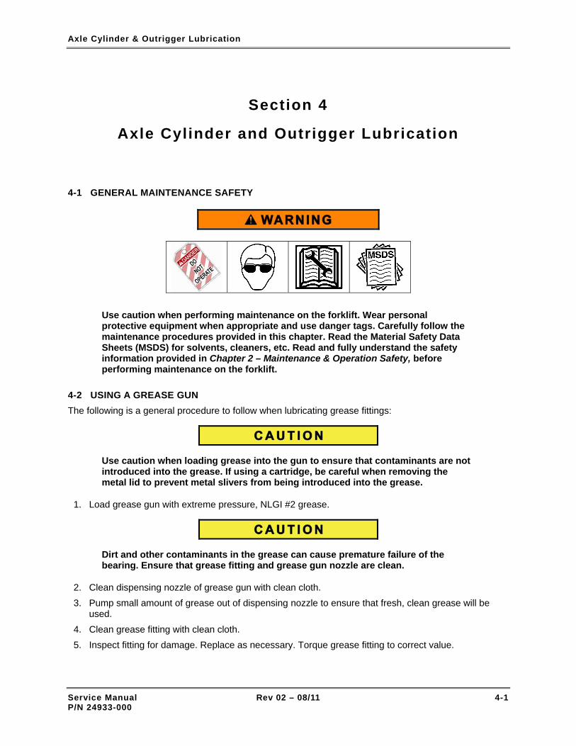
Axle Cylinder & Outrigger Lubrication
Section 4
Axle Cylinder and Outrigger Lubrication
4-1 GENERAL MAINTENANCE SAFETY
Use caution when performing maintenance on the forklift. Wear personal protective equipment when appropriate and use danger tags. Carefully follow the maintenance procedures provided in this chapter. Read the Material Safety Data Sheets (MSDS) for solvents, cleaners, etc. Read and fully understand the safety information provided in Chapter 2 – Maintenance & Operation Safety, before performing maintenance on the forklift.
4-2 USING A GREASE GUN The following is a general procedure to follow when lubricating grease fittings:
Use caution when loading grease into the gun to ensure that contaminants are not introduced into the grease. If using a cartridge, be careful when removing the metal lid to prevent metal slivers from being introduced into the grease.
1. Load grease gun with extreme pressure, NLGI #2 grease.
Dirt and other contaminants in the grease can cause premature failure of the bearing. Ensure that grease fitting and grease gun nozzle are clean.
2. Clean dispensing nozzle of grease gun with clean cloth. 3. Pump small amount of grease out of dispensing nozzle to ensure that fresh, clean grease will be
used. 4. Clean grease fitting with clean cloth. 5. Inspect fitting for damage. Replace as necessary. Torque grease fitting to correct value.
Service Manual Rev 02 – 08/11 4-1 P/N 24933-000

Axle Cylinder & Outrigger Lubrication
6. Attach grease gun dispensing nozzle to grease fitting.
A high-pressure grease gun delivers pressure up to 15,000 psi. The maximum pressure rating for forklift grease seals is 500 psi. Excessive applied pressure can damage the seal and lead to early failure.
NOTE: If back pressure is felt immediately when attempting to pump grease into the grease fitting, the fitting may be defective or the grease port and/or path may blocked.
7. Pump grease in front and rear axle cylinder and outrigger fittings until back-pressure is felt at grease gun lever, then stop pumping.
8. Start engine and operate forklift system or subsystem for several minutes. Shut-off engine, then re-grease fittings.
9. Clean excess grease off fitting with clean cloth.
10. After use, store grease gun (unpressurized) in a horizontal position to prevent leakage.
4-3 LUBRICATE AXLE CYLINDERS AND OUTRIGGERS
EVERY 50 HOURS OF OPERATION
Perform the following procedure to lubricate the axle cylinders and outriggers:
– TASK REQUIREMENTS –
Personnel One mechanic
Special tools and equipment Safety glasses Grease gun
Parts and consumable materials Danger tags (2) Grease, extreme pressure, NLGI #2 Clean cloth
Be very careful when working in and around the axle cylinders and outriggers. There are numerous pinch points that may cause serious personal injury.
Service Manual Rev 02 – 08/11 4-2 P/N 24933-000

Axle Cylinder & Outrigger Lubrication
NOTE: Outriggers are installed on XR1245, XR1255, XR1267, XR1270, XR2045, and XR2450 forklifts.
INITIAL SET-UP
1. Park forklift on level surface.
2. Set Travel Select lever to NEUTRAL (N).
3. Set Parking Brake switch to ON.
4. Retract boom and lower carriage to ground.
5. Extend outriggers.
6. Set Ignition switch to OFF.
7. Attach danger tags to steering wheel and ignition key. Refer to para. 2-5, for lockout-tagout procedure.
LUBRICATION
1. See Figures 4-1 and 4-2 for location of front and rear axle cylinder and outrigger grease fittings.
2. Lubricate front and rear axle cylinder and outrigger grease fittings in accordance with para. 4.2. (Note that some models have trunnion mounted cylinders installed, and will only have a grease fitting at the bottom of the cylinder).
Figure 4-1. Front and Rear Axle Cylinder Grease Fittings
Service Manual Rev 02 – 08/11 4-3 P/N 24933-000

Axle Cylinder & Outrigger Lubrication
Figure 4-2. Outrigger Grease Fittings – XR1245/1255/1267/1270/2045/2450 (Sheet 1 of 2)
Service Manual Rev 02 – 08/11 4-4 P/N 24933-000

Axle Cylinder & Outrigger Lubrication
Figure 4-2. Outrigger Grease Fittings – XR1245/1255/1267/1270/2045/2450 (Sheet 2 of 2)
Service Manual Rev 02 – 08/11 4-5 P/N 24933-000

Axle Cylinder & Outrigger Lubrication
Service Manual Rev 02 – 08/11 4-6 P/N 24933-000
THIS PAGE INTENTIONALLY LEFT BLANK

Engine
Section 5
Engine
5-1 GENERAL MAINTENANCE SAFETY
Use caution when performing maintenance on the forklift. Wear personal protective equipment when appropriate and use danger tags. Carefully follow the maintenance procedures provided in this chapter. Read the Material Safety Data Sheets (MSDS) for solvents, cleaners, etc. Read and fully understand the safety information provided in Chapter 2 – Maintenance & Operation Safety, before performing maintenance on the forklift.
5-2 CHECK ENGINE OIL LEVEL
EVERY 8 HOURS OF OPERATION
Perform the following procedure to check the engine oil level and add oil if required:
– TASK REQUIREMENTS –
Personnel One mechanic
Special tools and equipment Safety glasses Funnel
Parts and consumable materials Danger tags (2) Clean cloth Oil, 15W-40 API CG4
INITIAL SET-UP
1. Park forklift on level surface.
2. Set Travel Select lever to NEUTRAL (N).
Service Manual Rev 02 – 08/11 5-1 P/N 24933-000

Engine
3. Set Parking Brake switch to ON.
4. Retract boom and lower carriage. Allow sufficient space to open forklift covers.
5. Set Ignition switch to OFF.
6. Attach danger tags to steering wheel and ignition key. Refer to para. 2-5, for lockout-tagout procedure.
CHECK OIL LEVEL
1. Open engine cover (Figure 1-2).
2. Pull dipstick (Figure 5-1) from engine and wipe with clean cloth.
3. Re-insert dipstick in engine and remove to check amount of oil in crankcase. If oil level is below upper notch on dipstick, add oil to crankcase.
ADD OIL
1. Remove engine oil fill cap from valve cover (Figure 5-1).
2. Using clean funnel, pour oil into valve cover opening.
3. Use dipstick to recheck oil level.
4. Repeat Steps 2 and 3 until oil level reaches second notch on dipstick.
5. Install oil fill cap in valve cover.
6. Close engine cover.
Figure 5-1. Engine Oil Fill Cap and Dipstick
Service Manual Rev 02 – 08/11 5-2 P/N 24933-000

Engine
5-3 CHECK ENGINE COOLANT LEVEL
EVERY 8 HOURS OF OPERATION
The engine coolant level can easily be checked by looking at the opening in engine cover (Figure 5-2). The coolant level in the overflow tank (behind the opening) should be at mid level. If the coolant level is low, perform the following procedure to add coolant to the cooling system:
– TASK REQUIREMENTS –
Personnel One mechanic
Special tools and equipment Safety glasses Funnel
Parts and consumable materials Danger tags (2) Coolant, 50%/50% mixture of ethylene glycol and water (normal). Maximum amount of ethylene glycol in mixture must not exceed 70%
DO NOT leave coolant out where children or pets can get to it. Coolant has a sweet smell but is very toxic.
NOTE: If the overflow tank contains some coolant, coolant can be added directly to the tank to achieve the proper amount of coolant in the cooling system. If the overflow tank is empty, then coolant must be added to BOTH the radiator and the overflow tank.
INITIAL SET-UP
1. Park forklift on level surface.
2. Set Travel Select lever to NEUTRAL (N).
3. Set Parking Brake switch to ON.
4. Retract boom and lower carriage. Allow sufficient space to open forklift covers.
5. Set Ignition switch to OFF.
6. Attach danger tags to steering wheel and ignition key. Refer to para. 2-5, for lockout-tagout procedure.
ADD COOLANT TO OVERFLOW TANK
1. Open engine cover (Figure 1-2).
2. Remove cap from overflow tank (Figure 5-3).
Service Manual Rev 02 – 08/11 5-3 P/N 24933-000

Engine
3. Using clean funnel, pour coolant into overflow tank until tank is approximately half full.
ADD COOLANT TO RADIATOR AND OVERFLOW TANK
NEVER open a radiator cap on a hot engine. The radiator is pressurized and the coolant could spurt out and scald you
1. Let engine cool down completely.
2. Cover vent (Figure 5-3) with cloth. Turn vent to counter-clockwise (CCW) to release any pressure stored in radiator.
3. Remove radiator cap.
4. Using clean funnel, pour coolant into radiator until radiator core is completely covered.
5. Remove cloth from vent and turn clockwise (CW) until closed. Replace radiator cap.
6. Open overflow tank cap.
7. Using clean funnel, pour coolant into overflow tank until tank is approximately half full. Close cap.
8. Start engine and operate until engine reaches normal operating temperature.
9. Check coolant level in overflow tank. Add coolant as required.
10. Close engine cover.
Figure 5-2. Coolant Level Indicator
Service Manual Rev 02 – 08/11 5-4 P/N 24933-000

Engine
Figure 5-3. Radiator
5-4 CHECK FOR OIL AND COOLANT LEAKS
EVERY 8 HOURS OF OPERATION
Perform the following procedure to check the engine for oil and coolant leaks:
– TASK REQUIREMENTS –
Personnel One mechanic
Special tools and equipment Safety glasses
Parts and consumable materials Danger tags (2) Clean cloth
INITIAL SET-UP
1. Park forklift on level surface.
2. Set Travel Select lever to NEUTRAL (N).
3. Set Parking Brake switch to ON.
4. Retract boom and lower carriage. Allow sufficient space to open forklift covers.
5. Set Ignition switch to OFF.
6. Attach danger tags to steering wheel and ignition key. Refer to para. 2-5, for lockout-tagout procedure.
Service Manual Rev 02 – 08/11 5-5 P/N 24933-000

Engine
CHECK FOR OIL AND COOLANT LEAKS
1. Open engine and radiator covers (Figure 1-2).
2. Check ground beneath engine for evidence of oil and coolant leaks.
3. Check top, sides, and underside of engine for evidence of oil and coolant leaks.
4. Check all hoses and tubing for evidence of leaks.
5. Close engine and radiator covers.
5-5 CHECK FOR WATER IN FUEL-WATER SEPARATOR
EVERY 8 HOURS OF OPERATION
Perform the following procedure to check for water in the fuel-water separator:
– TASK REQUIREMENTS –
Personnel One mechanic
Special tools and equipment Safety glasses Container
Parts and consumable materials Danger tags (2)
INITIAL SET-UP
1. Park forklift on level surface.
2. Set Travel Select lever to NEUTRAL (N).
3. Set Parking Brake switch to ON.
4. Retract boom and lower carriage. Allow sufficient space to open forklift covers.
5. Set Ignition switch to OFF.
6. Attach danger tags to steering wheel and ignition key. Refer to para. 2-5, for lockout-tagout procedure.
DRAIN WATER
1. Open engine cover (Figure 1-2).
2. Place container beneath fuel-water separator.
3. Open drain valve (Figure 5-4).
4. If water does not drain, loosen fill valve.
5. When water has completely drained, close drain valve.
6. Hand tighten fill valve. DO NOT over tighten.
7. Close engine cover.
Service Manual Rev 02 – 08/11 5-6 P/N 24933-000

Engine
Figure 5-4. Fuel-Water Separator
Service Manual Rev 02 – 08/11 5-7 P/N 24933-000

Engine
5-6 EMPTY AIR FILTER DUST CUP
EVERY 8 HOURS OF OPERATION
Perform the following procedure to empty the air filter dust cup:
– TASK REQUIREMENTS –
Personnel One mechanic
Special tools and equipment Safety glasses
Parts and consumable materials Danger tags (2) Clean, disposable cloth
INITIAL SET-UP
1. Park forklift on level surface.
2. Set Travel Select lever to NEUTRAL (N).
3. Set Parking Brake switch to ON.
4. Retract boom and lower carriage. Allow sufficient space to open forklift covers.
5. Set Ignition switch to OFF.
6. Attach danger tags to steering wheel and ignition key. Refer to para. 2-5, for lockout-tagout procedure.
EMPTY DUST CUP
1. Open engine cover (Figure 1-2).
2. Loosen thumb screw (Figure 5-5) on dust cup clamp.
3. Remove clamp.
4. Remove dust cup.
5. Clean out dust cup with clean, disposable cloth. Dampen cloth if necessary.
Use caution when replacing the air filters. The engine is highly vulnerable to abrasive dust contaminants during the servicing process when the filters are removed from the housing.
NOTE: The least efficient time in the life of an air filter element is when it is new. Filter elements increase in efficiency as dust builds up on the media. The filters should only be changed when the dust build-up is beginning to restrict engine air intake.
6. Remove main filter and safety filter and inspect. Replace if dirty. (Refer to para. 5-13.)
Service Manual Rev 02 – 08/11 5-8 P/N 24933-000

Engine
7. Position dust cup on air filter assembly body.
8. Attach dust cup to air filter assembly body with clamp. Tighten thumb screw.
9. Close engine cover.
Figure 5-5. Engine Air Filter Assembly
Service Manual Rev 02 – 08/11 5-9 P/N 24933-000

Engine
5-7 CHECK CONDITION AND TENSION OF DRIVE BELTS
EVERY 8 HOURS OF OPERATION
Perform the following procedure to check the condition and tension of the engine drive belts:
– TASK REQUIREMENTS –
Personnel One mechanic
Special tools and equipment Safety glasses Tensiometer
Parts and consumable materials Danger tags (2)
INITIAL SET-UP
1. Park forklift on level surface.
2. Set Travel Select lever to NEUTRAL (N).
3. Set Parking Brake switch to ON.
4. Retract boom and lower carriage. Allow sufficient space to open forklift covers.
5. Set Ignition switch to OFF.
6. Attach DANGER – DO NOT OPERATE tags to steering wheel and ignition key.
CHECK CONDITION AND TENSION OF BELTS
1. Open engine cover (Figure 1-2).
2. Locate midpoint of belt between engine and alternator.
3. Alternately push and pull on belts to roughly measure belt tension. Belts should have approximately ½" total slack. Refer to para. 5-15 for belt tension adjustment procedure.
4. Close engine cover.
5-8 CHANGE ENGINE OIL AFTER FIRST 50 HOURS AND EVERY 250 HOURS OF OPERATION
Perform the following procedure to change the engine oil:
– TASK REQUIREMENTS –
Personnel One mechanic
Service Manual Rev 02 – 08/11 5-10 P/N 24933-000

Engine
Special tools and equipment Safety glasses Torque wrench Funnel Container
Parts and consumable materials Danger tags (2) Oil, 15W-40 API CG4 (8 qts) (See Figure 5-7 for additional info.)
INITIAL SET-UP
1. Park forklift on level surface. This will help ensure an accurate reading on dipstick.
2. Set Travel Select lever to NEUTRAL (N).
3. Set Parking Brake switch to ON.
4. Retract boom and lower carriage. Allow sufficient space to open forklift covers.
5. Operate engine until warm.
6. Set Ignition switch to OFF.
7. Attach danger tags to steering wheel and ignition key. Refer to para. 2-5, for lockout-tagout procedure.
Do not exceed the correct level of engine oil. An excess of engine oil could enter the breather valve. This could cause the engine speed to increase rapidly without control.
Discard the used engine oil in a safe place and in accordance with local regulations.
DRAIN AND FILL CRANKCASE
1. Open engine cover (Figure 1-2).
2. Place container below engine oil pan.
3. See Figure 5-6. Remove oil pan drain plug (1) and O-ring.
4. Drain engine oil into container.
5. Ensure O-ring is not damaged. Install drain plug and O-ring. Torque drain plug to 25 ft-lbs.
6. Add approximately 8 quarts of oil to crankcase until oil level reaches fill line on dipstick (2).
7. Remove container and properly dispose of engine oil.
8. Start engine and check for oil leaks.
Service Manual Rev 02 – 08/11 5-11 P/N 24933-000

Engine
Figure 5-6. Oil Drain Plug and Dipstick
Figure 5-7. Recommended Engine Oil Viscosity Grades
Service Manual Rev 02 – 08/11 5-12 P/N 24933-000

Engine
5-9 REPLACE OIL FILTERS AFTER FIRST 50 HOURS AND EVERY 250 HOURS OF OPERATION
NOTE: The engine is equipped with two oil filters, an element-type oil filter and a cartridge-type oil filter. If only the engine oil is to be changed, refer to para. 5-8 for oil change procedures.
Perform the following procedures to replace the element-type and canister-type oil filters:
– TASK REQUIREMENTS –
Personnel One mechanic
Special tools and equipment Safety glasses Torque wrench Funnel Container Strap wrench
Parts and consumable materials Danger tags (2) Element-type oil filter Canister-type oil filter
• Discard the used engine oil and filters in a safe place and in accordance with local regulations.
• It is important that only Xtreme Manufacturing or Perkins oil filters are used. The use of other filters may damage the engine and void the warranty.
INITIAL SET-UP
1. Park forklift on level surface.
2. Set Travel Select lever to NEUTRAL (N).
3. Set Parking Brake switch to ON.
4. Retract boom and lower carriage. Allow sufficient space to open forklift covers.
5. Operate engine until warm.
6. Set Ignition switch to OFF.
7. Attach danger tags to steering wheel and ignition key. Refer to para. 2-5, for lockout-tagout procedure.
Service Manual Rev 02 – 08/11 5-13 P/N 24933-000

Engine
DRAIN OIL FROM CRANKCASE
1. Open engine cover (Figure 1-2).
2. Position suitable container below engine oil pan.
3. See Figure 5-6. Remove oil pan drain plug (1) and O-ring.
4. Drain engine oil into container.
REPLACE ELEMENT-TYPE OIL FILTER
1. See Figure 5-8. Put suitable container below oil filter (A4).
2. Remove plug (A2) and drain oil from filter.
3. Install ½” square drive ratchet into recess (A1) and remove casing (A3).
4. Discard old filter element.
5. Clean filter casing and replace seal (B2).
6. Install new filter element (B1) into casing and rotate element to locate it into position.
7. Install new seal on drain plug (A2).
8. Torque plug to 9 ft-lbs.
9. Lubricate seal (B2) with clean engine oil.
10. Fill casing with clean engine oil.
11. Install filter (B1) into casing.
12. Torque casing (A3) to 18 ft-lbs.
13. Remove container and properly dispose of engine oil.
Figure 5-8. Element-Type Oil Filter
Service Manual Rev 02 – 08/11 5-14 P/N 24933-000

Engine
REPLACE CANISTER-TYPE OIL FILTER
NOTE: The canister contains a valve and a special tube to ensure that engine oil does not drain from the filter when the oil is changed.
1. See Figure 5-9. Position container below oil filter canister (2).
2. Remove filter canister (2) with strap wrench. Ensure adapter is secure in filter head.
3. Discard canister (2).
4. Clean filter head (3).
5. Fill canister with new oil.
6. Lubricate top of new canister seal (1) with clean oil.
7. Install new canister (2) and tighten by hand. DO NOT use strap wrench.
8. Remove container and properly dispose of engine oil.
9. Close engine cover.
Figure 5-9. Canister-Type Oil Filter
FILL CRANKCASE WITH OIL
1. Ensure O-ring is not damaged. Install drain plug and O-ring. Torque plug to 25 ft-lbs.
2. Add engine oil to crankcase until oil level reaches fill line on dipstick (2).
Service Manual Rev 02 – 08/11 5-15 P/N 24933-000

Engine
LEAK CHECK
1. Start engine
2. Check for leaks at crankcase drain plug and both filters.
3. When engine has cooled, check oil level on dipstick and add oil as needed.
5-10 REPLACE FUEL FILTER
EVERY 500 HOURS OF OPERATION
Perform the following procedure to replace the fuel filter:
– TASK REQUIREMENTS –
Personnel One mechanic
Special tools and equipment Safety glasses Container
Parts and consumable materials Danger tags (2) Fuel filter element Xtreme P/N 13952-008
• The combustible material of some components of the engine (certain seals, for example) can become extremely dangerous if it is burned. Never allow this burnt material to come into contact with the skin or eyes.
• Discard the used element and fuel in a safe place and in accordance with local regulations.
• Ensure the starter switch is in the off position before servicing or repairs are made to the fuel system, because fuel will be released if the lift pump has power.
• All fuel line valves must be closed before maintenance or repairs are made to the fuel system. If this is not done, the fuel system may drain.
• It is important that only genuine Xtreme parts are used. The use of parts that are not genuine Xtreme parts may damage the fuel pump and void the warranty.
• The pre-filter canister and main filter elements must be replaced at the same time.
• Do not allow dirt to enter the fuel system.
Service Manual Rev 02 – 08/11 5-16 P/N 24933-000

Engine
INITIAL SET-UP
1. Park forklift on level surface.
2. Set Travel Select lever to NEUTRAL (N).
3. Set Parking Brake switch to ON.
4. Retract boom and lower carriage. Allow sufficient space to open forklift covers.
5. Set Ignition switch to OFF.
6. Attach danger tags to steering wheel and ignition key. Refer to para. 2-5, for lockout-tagout procedure.
REPLACE FILTER
1. Open engine cover (Figure 1-2).
2. See Figure 5-10. Place container below fuel filter assembly to catch any fuel spillage.
3. Thoroughly clean outside surfaces of fuel filter assembly. Open drain tap (A1) at bottom of filter casing (B4) to drain fuel from filter.
4. Loosen and remove filter casing (B4) and element (B1) from fuel filter head.
5. Remove filter element (B1) from casing (B4). Press down on filter element (B1), against spring pressure, and rotate it counter-clockwise (CCW) to release it from filter casing (B4).
6. Put new filter element (B1) inside casing (B4) and press it down against spring pressure. Rotate it clockwise (CW) to lock it into casing (B4).
7. Lightly lubricate new seal (B3) with clean fuel and install in casing (B4).
8. Check that thread (B2) on inside of element is not damaged.
9. Install filter assembly on fuel filter head and tighten by hand until it contacts filter head. Tighten assembly ¼ of turn further by hand. DO NOT over tighten.
10. Close drain tap (A1) and remove container.
11. Before starter motor is engaged, operate lift pump for one minute to eliminate air from filter.
12. Start engine and check for fuel leaks.
Figure 5-10. Fuel Filter Element
Service Manual Rev 02 – 08/11 5-17 P/N 24933-000

Engine
5-11 CHECK SPECIFIC GRAVITY OF COOLANT
EVERY 500 HOURS OF OPERATION
Perform the following procedure to check the specific gravity of the coolant.
– TASK REQUIREMENTS –
Personnel One mechanic
Special tools and equipment Safety glasses Coolant hydrometer (with thermometer) Container
Parts and consumable materials Danger tags (2) Coolant, 50%/50% mixture of ethylene glycol and water (normal). Maximum amount of ethylene glycol in mixture must not exceed 70%
DO NOT leave coolant out where children or pets can get to it. It has a sweet smell but is very toxic.
INITIAL SET-UP
1. Park forklift on level surface.
2. Set Travel Select lever to NEUTRAL (N).
3. Set Parking Brake switch to ON.
4. Retract boom and lower carriage. Allow sufficient space to open forklift covers.
5. Attach danger tags to steering wheel and ignition key. Refer to para. 2-5, for lockout-tagout procedure.
CHECK SPECIFIC GRAVITY OF COOLANT
1. Open engine cover (Figure 1-2).
2. Start engine and operate until warm enough to open thermostat. Continue to run engine until coolant has circulated through cooling system.
3. Stop engine and allow to cool until temperature of coolant is below 140°F.
Service Manual Rev 02 – 08/11 5-18 P/N 24933-000

Engine
DO NOT drain the coolant while the engine is still hot and the system is under pressure. Dangerous hot coolant can be discharged.
4. See Figure 5-11. Open cap of coolant recovery tank.
5. Remove radiator cap.
6. Position container beneath radiator drain.
7. Open radiator drain to drain small amount of coolant into container.
8. Draw coolant from container into hydrometer and read hydrometer scale (refer to chart on Figure 5-12).
9. Add water or coolant to recovery tank to adjust strength of mixture as required.
10. Close radiator drain.
11. Install radiator cap.
12. Close coolant recovery tank cap.
13. Close engine cover.
Figure 5-11. Coolant Recovery Tank and Radiator Drain
Service Manual Rev 02 – 08/11 5-19 P/N 24933-000

Engine
Figure 5-12. Specific Gravity Chart
5-12 DRAIN AND FLUSH COOLING SYSTEM
EVERY 4,000 HOURS OF OPERATION
Perform the following procedure to drain and flush the cooling system:
– TASK REQUIREMENTS –
Personnel One mechanic
Special tools and equipment Safety glasses Containers (2)
Parts and consumable materials Danger tags (2) Coolant, 50%/50% mixture of ethylene glycol and water (normal). Maximum amount of ethylene glycol in mixture must not exceed 70%
Service Manual Rev 02 – 08/11 5-20 P/N 24933-000

Engine
DO NOT leave coolant out where children or pets can get to it. It has a sweet smell but is very toxic.
INITIAL SET-UP
1. Park forklift on level surface.
2. Set Travel Select lever to NEUTRAL (N).
3. Set Parking Brake switch to ON.
4. Retract boom and lower carriage. Allow sufficient space to open forklift covers.
5. Set Ignition switch to OFF.
6. Attach danger tags to steering wheel and ignition key. Refer to para. 2-5, for lockout-tagout procedure.
DO NOT drain the coolant while the engine is still hot and the system is under pressure. Dangerous hot coolant can be discharged.
DRAIN
1. Open engine and radiator covers (Figure 1-2). 2. Place cloth over radiator vent valve. Open vent. 3. Remove radiator cap. 4. Remove coolant recovery tank cap. 5. Place container beneath radiator pet cock (Figure 5-11). 6. Open radiator pet cock and allow coolant to drain into container. 7. Place container beneath cylinder block drain plug (Figure 5-12). 8. Remove cylinder block drain plug. Ensure that drain hole is not restricted. Allow coolant to drain into
container. 9. After radiator and engine block have drained, properly dispose of coolant.
10. Flush system with clean water. 11. Re-install cylinder block drain plug and torque to 30 ft-lbs. 12. Close radiator pet cock.
Service Manual Rev 02 – 08/11 5-21 P/N 24933-000

Engine
FILL
1. Fill radiator with coolant until core is covered. 2. Fill coolant recovery tank with coolant until one-half full. 3. Install radiator cap and close radiator vent valve. 4. Install coolant recovery tank cap. 5. Start engine and operate until engine reaches normal operating temperature. 6. Recheck coolant level in coolant recovery tank. If necessary, add coolant until tank is one-half full. 7. Close engine and radiator covers.
Figure 5-13. Cylinder Block Drain Plug
5-13 REPLACE AIR FILTERS
EVERY 500 HOURS OF OPERATION
Perform the following procedure to replace the air filters:
– TASK REQUIREMENTS –
Personnel One mechanic
Special tools and equipment Safety glasses
Service Manual Rev 02 – 08/11 5-22 P/N 24933-000

Engine
Parts and consumable materials Danger tags (2) Clean, disposable cloth Main air filter element Xtreme P/N 14362-010 Safety air filter element Xtreme P/N 14362-011
Use caution when replacing the air filters. The engine is highly vulnerable to abrasive dust contaminants during the servicing process when the filters are removed from the housing.
NOTE: The least efficient time in the life of an air filter element is when it is new. Filter elements increase in efficiency as dust builds up on the media. The filters should only be changed when the dust build-up is beginning to restrict engine air intake.
INITIAL SET-UP
1. Park forklift on level surface.
2. Set Travel Select lever to NEUTRAL (N).
3. Set Parking Brake switch to ON.
4. Retract boom and lower carriage. Allow sufficient space to open forklift covers.
5. Set Ignition switch to OFF.
6. Attach danger tags to steering wheel and ignition key. Refer to para. 2-5, for lockout-tagout procedure.
REPLACE AIR FILTER
1. Open engine cover (Figure 1-2).
2. See Figure 5-5. Loosen thumb screw on dust cup clamp.
3. Remove clamp.
4. Remove dust cup.
5. Inspect dust cup for cleanliness. If dirty, clean with clean, disposable cloth. Dampen cloth if necessary.
6. Replace main and safety air filter elements.
7. Position dust cup on air filter assembly body.
8. Attach dust cup to air filter assembly body with clamp. Tighten thumb screw.
9. Close engine cover.
Service Manual Rev 02 – 08/11 5-23 P/N 24933-000
Engine
5-14 CHECK AIR FILTER AFTER EVERY 8 HOURS OF OPERATION AND 250 HOURS OF OPERATION
NOTE: The air filter should be checked after every 8 hours of operation only during extremely dusty conditions. Normal inspection interval is 250 hours.
Perform the following procedure to check the engine air filter:
– TASK REQUIREMENTS –
Personnel One mechanic
Special tools and equipment Safety glasses
Parts and consumable materials Danger tags (2)
Use caution when replacing the air filters. The engine is highly vulnerable to abrasive dust contaminants during the servicing process when the filters are removed from the housing.
NOTE: The least efficient time in the life of an air filter element is when it is new. Filter elements increase in efficiency as dust builds up on the media. The filters should only be changed when the dust build-up is beginning to restrict engine air intake.
INITIAL SET-UP
1. Park forklift on level surface.
2. Set Travel Select lever to NEUTRAL (N).
3. Set Parking Brake switch to ON.
4. Retract boom and lower carriage. Allow sufficient space to open forklift covers.
5. Set Ignition switch to OFF.
6. Attach danger tags to steering wheel and ignition key. Refer to para. 2-5, for lockout-tagout procedure.
INSPECT FILTER
1. Open engine cover (Figure 1-2).
2. Loosen thumb screw on clamp (Figure 5-5).
3. Remove dust cup from air filter body.
4. Remove main and safety filter elements from filter body.
Service Manual Rev 02 – 08/11 5-24 P/N 24933-000

Engine
5-15 CHECK CONDITION AND TENSION OF DRIVE BELTS
EVERY 500 HOURS OF OPERATION
Perform the following procedure to inspect and adjust the tension of the engine drive belts:
– TASK REQUIREMENTS –
Personnel One mechanic
Special tools and equipment Belt tensiometer Safety glasses
Parts and consumable materials Danger tags (2)
INITIAL SET-UP
1. Park forklift on level surface.
2. Set Travel Select lever to NEUTRAL (N).
3. Set Parking Brake switch to ON.
4. Retract boom and lower carriage. Allow sufficient space to open forklift covers.
5. Set Ignition switch to OFF.
6. Attach danger tags to steering wheel and ignition key. Refer to para. 2-5, for lockout-tagout procedure.
CHECK CONDITION OF DRIVE BELTS
1. Open engine cover (Figure 1-2).
2. Check belts for following defects:
• Cuts, cracks, or damage.
• Excessive wear.
• Dryness (loss of flexibility).
• Contamination with oil or coolant.
• Looseness.
3. If belts are defective, replace as a set. If belts are loose, refer to procedure below.
CHECK AND ADJUST BELT TENSION
1. Place belt tensiometer (Figure 5-14, A1) at center of longest free length and check tension. Correct tension is 120 ft-lbs.
2. Loosen pivot fastener (Figure 5-14, B1) of alternator and adjustment link fasteners (Figure 5-14, B2 and C1).
Service Manual Rev 02 – 08/11 5-25 P/N 24933-000

Engine
3. Change position of alternator to increase or decrease tension on belt. Torque alternator retaining bolt (Figure 5-14, B1) and tension adjusting bolts (Figure5-14, B2, C1) to 16 ft-lbs.
4. Check belt tension again to ensure that it is still correct. If new belts are installed, belt tension must be checked again after 20 hours of operation.
Figure 5-14. Checking Drive Belt Tension
Service Manual Rev 02 – 08/11 5-26 P/N 24933-000
Engine
5-16 CHECK AND ADJUST VALVE TIP CLEARANCES
EVERY 1,000 HOURS OF OPERATION
Perform the following procedure to check and adjust the valve tip clearances.
– TASK REQUIREMENTS –
Personnel One mechanic
Special tools and equipment Feeler gauge Safety glasses
Parts and consumable materials Danger tags (2)
INITIAL SET-UP
1. Park forklift on level surface.
2. Set Travel Select lever to NEUTRAL (N).
3. Set Parking Brake switch to ON.
4. Retract boom and lower carriage. Allow sufficient space to open forklift covers.
5. Set Ignition switch to OFF.
6. Attach danger tags to steering wheel and ignition key. Refer to para. 2-5, for lockout-tagout procedure.
CHECK AND ADJUST VALVE CLEARANCE
1. Open engine cover (Figure 1-2).
NOTE: The valve clearances are checked between the top of the valve stem and the rocker lever (Figure 5-15, A), while the engine is engine cold. The correct clearance for the inlet valves is 0.008” and 0.018” for the exhaust valves. The valve positions are shown in (B). Refer to Table 5-1 for valve and cylinder numbers.
NOTE: The number 1 cylinder is the furthest from the flywheel end of the engine.
2. Rotate crankshaft in normal direction until inlet valve (B7) of number 4 cylinder has just opened and exhaust valve (B8) of same cylinder has not closed completely. Check clearances of valves (B1/B2) and (B2) of number 1 cylinder and adjust them, if necessary.
3. Set valves (B3/B4) of number 2 cylinder as indicated above for number 4 cylinder. Check clearances of valves (B5/B6) of number 3 cylinder. Adjust valve clearance as required.
4. Set valves (B1/B2) of number 1 cylinder. Check clearances of valves (B7/B8) of number 4 cylinder. Adjust valve clearance as required.
5. Set valves (B5/B6) of number 3 cylinder. Check clearances of valves (B3/B4) of number 2 cylinder. Adjust valve clearance as required.
Service Manual Rev 02 – 08/11 5-27 P/N 24933-000

Engine
Table 5-1. Cylinder and Valve Numbers
CYLINDER NO.
1 2 3 4
VALVE NO. / TYPE (I = INLET – E = EXHAUST)
1 2 3 4 5 6 7 8
I E I E I E I E
Figure 5-15. Checking and Adjusting Engine Valve Clearances
Service Manual Rev 02 – 08/11 5-28 P/N 24933-000
Engine
5-17 CHECK ENGINE HOSES AND CONNECTIONS
EVERY 500 HOURS OF OPERATION
Perform the following procedure to check the engine hoses, tubing, and connections for leaks, damage, and tightness:
– TASK REQUIREMENTS –
Personnel One mechanic
Special tools and equipment Safety glasses Drop light
Parts and consumable materials Danger tags (2)
INITIAL SET-UP
1. Park forklift on level surface.
2. Set Travel Select lever to NEUTRAL (N).
3. Set Parking Brake switch to ON.
4. Retract boom and lower carriage. Allow sufficient space to open forklift covers.
5. Set Ignition switch to OFF.
6. Attach danger tags to steering wheel and ignition key. Refer to para. 2-5, for lockout-tagout procedure.
INSPECTION
1. Open engine cover (Figure 1-2).
2. Inspect engine hoses, tubing, and connections for the following defects:
• Evidence of leakage.
• Loose or corroded clamps.
• Bulges.
• Cracks.
• Cuts.
• Soft or mushy spots.
• Hard spots.
3. Replace any defective hoses, tubing, or clamps.
4. Check system for leaks.
Service Manual Rev 02 – 08/11 5-29 P/N 24933-000

Engine
5-18 CHECK RADIATOR HOSES AND CONNECTIONS
EVERY 500 HOURS OF OPERATION
Perform the following procedure to check the radiator hoses and connections for leaks, damage, and tightness:
– TASK REQUIREMENTS –
Personnel One mechanic
Special tools and equipment Safety glasses Drop light
Parts and consumable materials Danger tags (2)
INITIAL SET-UP
1. Park forklift on level surface.
2. Set Travel Select lever to NEUTRAL (N).
3. Set Parking Brake switch to ON.
4. Retract boom and lower carriage. Allow sufficient space to open forklift covers.
5. Set Ignition switch to OFF.
6. Attach danger tags to steering wheel and ignition key. Refer to para. 2-5, for lockout-tagout procedure.
INSPECTION
1. Open engine cover (Figure 1-2).
2. See Figure 5-16. Inspect hoses connected to radiator for the following defects:
• Signs of leakage.
• Loose or corroded clamps.
• Bulges.
• Cracks.
• Cuts.
• Soft or mushy spots.
• Hard spots.
3. Replace any defective hoses or clamps.
4. Check system for leaks.
Service Manual Rev 02 – 08/11 5-30 P/N 24933-000

Engine
Figure 5-16. Radiator Hoses and Connections
5-19 CHECK ENGINE WIRING AND CONNECTIONS
EVERY 500 HOURS OF OPERATION
Perform the following procedure to check the engine wiring and connections for damage and tightness:
– TASK REQUIREMENTS –
Personnel One mechanic
Special tools and equipment Safety glasses Drop light
Parts and consumable materials Danger tags (2)
Service Manual Rev 02 – 08/11 5-31 P/N 24933-000

Engine
INITIAL SET-UP
1. Park forklift on level surface.
2. Set Travel Select lever to NEUTRAL (N).
3. Set Parking Brake switch to ON.
4. Retract boom and lower carriage. Allow sufficient space to open forklift covers.
5. Set Ignition switch to OFF.
6. Attach danger tags to steering wheel and ignition key. Refer to para. 2-5, for lockout-tagout procedure.
INSPECTION
1. Open engine cover (Figure 1-2).
2. Inspect engine wiring and connections for the following defects:
• Loose connections.
• Damaged connectors.
• Dirty or contaminated connectors.
• Loose or missing clamps and hardware.
• Misrouted wires and cables.
• Damaged or missing cable jacket.
• Loose or corroded ground connections.
3. Repair or replace any defective wiring and connections.
4. Check system for proper operation.
5-20 CHECK FOR OIL, COOLANT, AND FUEL LEAKS
AFTER FIRST 50 HOURS OF OPERATION
Perform the following procedure to check the engine for oil, coolant, and fuel leaks:
– TASK REQUIREMENTS –
Personnel One mechanic
Special tools and equipment Safety glasses Drop light Creeper
Parts and consumable materials Danger tags (2)
Service Manual Rev 02 – 08/11 5-32 P/N 24933-000

Engine
INITIAL SET-UP
1. Park forklift on level surface.
2. Set Travel Select lever to NEUTRAL (N).
3. Set Parking Brake switch to ON.
4. Retract boom and lower carriage. Allow sufficient space to open forklift covers.
5. Set Ignition switch to OFF.
6. Attach danger tags to steering wheel and ignition key. Refer to para. 2-5, for lockout-tagout procedure.
INSPECTION
1. Open engine cover (Figure 1-2).
2. Inspect the following components and areas for evidence of oil, coolant, and fuel leaks:
Some leaks can be repaired simply by tightening a loose screw or screws. However, note that the proper method for tightening the screws of a component, such as the oil pan, is with a torque wrench. Also note that the screws should be tightened in a specific sequence to prevent warping the component. All leaks should be troubleshot and repaired by a qualified mechanic.
• Engine valve cover.
• Engine head.
• Engine oil pan.
• Water pump.
• Thermostat.
• Turbocharger.
• Fuel pump.
Service Manual Rev 02 – 08/11 5-33 P/N 24933-000

Engine
Service Manual Rev 02 – 08/11 5-34 P/N 24933-000
THIS PAGE INTENTIONALLY LEFT BLANK

Transmission, Axles, & Driveshafts
Section 6
Transmission, Axles, & Driveshafts
6-1 GENERAL MAINTENANCE SAFETY
Use caution when performing maintenance on the forklift. Wear personal protective equipment when appropriate and use danger tags. Carefully follow the maintenance procedures provided in this chapter. Read the Material Safety Data Sheets (MSDS) for solvents, cleaners, etc. Read and fully understand the safety information provided in Chapter 2 – Maintenance & Operation Safety, before performing maintenance on the forklift.
6-2 USING A GREASE GUN
The following is a general procedure to follow when lubricating grease fittings:
Use caution when loading grease into the gun to ensure that contaminants are not introduced into the grease. If using a cartridge, be careful when removing the metal lid to prevent metal slivers from being introduced into the grease.
1. Load grease gun with extreme pressure, NLGI #2 grease.
Dirt and other contaminants in the grease can cause premature failure of the bearing. Ensure that grease fitting and grease gun nozzle are clean.
2. Clean dispensing nozzle of grease gun with clean cloth.
3. Pump small amount of grease out of dispensing nozzle to ensure that fresh, clean grease will be used.
4. Clean grease fitting with clean cloth.
Service Manual Rev 02 – 08/11 6-1 P/N 24933-000
Transmission, Axles, & Driveshafts
5. Inspect fitting for damage. Replace as necessary. Torque grease fitting to correct value.
6. Attach grease gun dispensing nozzle to grease fitting.
A high-pressure grease gun delivers pressure up to 15,000 psi. The maximum pressure rating for forklift grease seals is 500 psi. Excessive applied pressure can damage the seal and lead to early failure.
NOTE: If back pressure is felt immediately when attempting to pump grease into the grease fitting, the fitting may be defective or the grease port and/or path may blocked.
7. Pump grease in front and rear axle fittings until back-pressure is felt at grease gun lever, then stop pumping.
8. Start engine and operate forklift system or subsystem for several minutes. Shut-off engine, then re-grease fittings.
9. Clean excess grease off fitting with clean cloth.
10. After use, store grease gun (unpressurized) in a horizontal position to prevent leakage.
6-3 LUBRICATE AXLE GREASE FITTINGS
EVERY 250 HOURS OF OPERATION
Perform the following procedure to lubricate the front and rear axle grease fittings:
– TASK REQUIREMENTS –
Personnel One mechanic
Special tools and equipment Safety glasses Grease gun
Parts and consumable materials Danger tags (2) Grease, extreme pressure, NLGI #2
INITIAL SET-UP
1. Park forklift on level surface.
2. Set Travel Select lever to NEUTRAL (N).
3. Set Parking Brake switch to ON.
4. Retract boom and lower carriage. Allow sufficient space to open forklift covers.
5. Set Ignition switch to OFF.
6. Attach danger tags to steering wheel and ignition key. Refer to para. 2-5, for lockout-tagout procedure.
Service Manual Rev 02 – 08/11 6-2 P/N 24933-000

Transmission, Axles, & Driveshafts
LUBRICATE FITTINGS
1. See Figure 6-1 for location of axle grease fittings. Each axle has six grease fittings.
2. Lubricate front and rear axle grease fittings in accordance with para. 6-3.
NOTE: EACH AXLE HAS SIX GREASE FITTINGS.
Figure 6-1. Axle Grease Fittings
Service Manual Rev 02 – 08/11 6-3 P/N 24933-000

Transmission, Axles, & Driveshafts
6-4 LUBRICATE DRIVESHAFTS
AFTER FIRST 50 HOURS OF OPERATION AND EVERY 250 HOURS OF OPERATION
Perform the following procedure to lubricate the front and rear driveshafts:
– TASK REQUIREMENTS –
Personnel One mechanic
Special tools and equipment Safety glasses Wheel chocks (4) Creeper Grease gun
Parts and consumable materials Danger tags (2) Grease, extreme pressure, NLGI #2
INITIAL SET-UP
1. Park forklift on level surface.
2. Set Travel Select lever to NEUTRAL (N).
3. Set Parking Brake switch to ON.
4. Retract boom and lower carriage. Allow sufficient space to open forklift covers.
5. Set Ignition switch to OFF.
6. Attach danger tags to steering wheel and ignition key. Refer to para. 2-5, for lockout-tagout procedure.
7. Place wheel chocks in front of front tires and behind rear tires.
LUBRICATE DRIVESHAFTS
1. See Figure 6-1 for location of driveshaft grease fittings. Each driveshaft has three grease fittings.
2. Gain access to underside of forklift chassis.
3. Lubricate front and rear driveshaft grease fittings in accordance with para. 6-4.
Service Manual Rev 02 – 08/11 6-4 P/N 24933-000

Transmission, Axles, & Driveshafts
Figure 6-2. Driveshaft Grease Fittings
Service Manual Rev 02 – 08/11 6-5 P/N 24933-000

Transmission, Axles, & Driveshafts
6-5 REPLACE TRANSMISSION FILTERS AND FLUID
FIRST 50 HOURS (FILTER), FIRST 500 HOURS (FILTER), THEN EVERY 1000 HOURS (FILTER & FLUID) OF OPERATION
Perform the following procedure to replace the transmission filters and fluid:
– TASK REQUIREMENTS –
Personnel One mechanic
Special tools and equipment Safety glasses Torque wrench Container
Parts and consumable materials Danger tags (2)
Transmission fluid, Dexron III XR842 (13.5 qts) XR1045/1245/1255/1267/1270 1534/1642/2034/2045/2450/3034 (17 qts)
Oil filter XR842 P/N 14106-010 XR1267/1270/1642/ 2034/2045/2450/3034 P/N 14107-010 XR1045/1245/1255/1534 P/N 14108-010
INITIAL SET-UP
1. Park forklift on level surface.
2. Set Travel Select lever to NEUTRAL (N).
3. Set Parking Brake switch to ON.
4. Retract boom and lower carriage. Allow sufficient space to open forklift covers.
5. Set Ignition switch to OFF.
6. Attach danger tags to steering wheel and ignition key. Refer to para. 2-5, for lockout-tagout procedure.
DRAIN
1. Remove drain plug (Figure 6-4) and drain oil from the transmission into a suitable container.
2. Remove oil filter and dispose of in accordance with local regulations.
3. Clean drain plug and mating surface with a clean rag or shop towel.
Service Manual Rev 02 – 08/11 6-6 P/N 24933-000

Transmission, Axles, & Driveshafts
FILL
1. Install drain plug and torque to 44 ft-lbs.
2. Apply a thin film of oil on delivery filter seal. Install delivery filter on transmission and tighten hand-tight.
3. Remove dipstick (DANA) or fill plug (CARRARO).
4. Refill transmission with Dexron III transmission fluid (as noted in chart on page 6-6).
5. Replace dipstick (DANA) or fill plug (CARRARO). Hand tighten fill plug, then tighten 1/2 turn further (CARRARO).
6. Start engine and run until engine is warm.
7. Set Travel Select lever to F (Forward). Alternately set Gear Select switch to 1st, 2nd, 3rd, and 4th gears.
8. Set Travel Select lever to R (Reverse). Alternately set Gear Select switch to 1st, 2nd, 3rd, and 4th gears.
9. Re-check transmission fluid level. Add fluid as required.
DANA842 / 1267 / 1270 / 1642
2034 / 2045 / 2450 / 3034
CARRARO1045 / 1245 / 1255 / 1534
Filter
Drain plug
Fill Port
Filter
Drain plug
Fill Port
Figure 6-3. Transmission Plugs and Filters
Service Manual Rev 02 – 08/11 6-7 P/N 24933-000

Transmission, Axles, & Driveshafts
6-6 CHECK AXLE OIL LEVEL
EVERY 250 HOURS OF OPERATION
Perform the following procedure to check axle oil levels and add oil as required:
– TASK REQUIREMENTS –
Personnel One mechanic
Special tools and equipment Safety glasses Torque wrench
Parts and consumable materials Danger tags (2) Safety solvent Oil, SAE 80W-90 EP API GL4 Oil, SAE 80W-90 EP API GL5
There are two different axles that may be installed on Model XR1045/1245/1255 forklifts. These axles have different lubrication requirements. One axle requires SAE 80W-90 EP API GL4 Oil; the other axle requires SAE 80W-90 EP API GL5 Oil. Always check the axle data plate to determine the correct lubricant and quantity required.
INITIAL SET-UP
1. Park forklift on level surface. 2. Set Travel Select lever to NEUTRAL (N). 3. Set Parking Brake switch to ON. 4. Retract boom and lower carriage. Allow sufficient space to open forklift covers. 5. Set Ignition switch to OFF. 6. Attach danger tags to steering wheel and ignition key. Refer to para. 2-5, for lockout-tagout
procedure.
CLEAN OIL BREATHER
1. Remove oil breather (Figure 6-4, View A). NOTE: Breather requires cleaning to prevent internal pressure build-up.
2. Clean breather with safety solvent.
3. Install breather and torque to 7 ft-lbs.
Service Manual Rev 02 – 08/11 6-8 P/N 24933-000

Transmission, Axles, & Driveshafts
CHECK AND FILL DIFFERENTIAL
1. Remove drain plug (Figure 6-4, View B) 2. Check oil level. Oil level should be at bottom of drain plug hole. If oil level is low, proceed to Step 3. If
oil level is OK, proceed to Step 4. 3. Use funnel with flexible spout to fill axle with oil. 4. Clean and install drain plug. Torque plug to 44 ft-lbs.
CHECK AND FILL AXLE
1. Remove fill plug (Figure 6-4, View C).
2. Check oil level. Oil level should be at bottom of fill plug hole. If oil level is low, proceed to Step 3. If oil level is OK, proceed to Step 4.
3. Use funnel with flexible spout to fill axle with oil.
4. Clean and install fill plug. Torque plug to 44 ft-lbs.
Service Manual Rev 02 – 08/11 6-9 P/N 24933-000
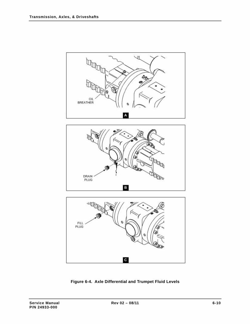
Transmission, Axles, & Driveshafts
Figure 6-4. Axle Differential and Trumpet Fluid Levels
Service Manual Rev 02 – 08/11 6-10 P/N 24933-000

Transmission, Axles, & Driveshafts
6-7 CHECK WHEEL-END OIL LEVEL
EVERY 250 HOURS OF OPERATION
Perform the following procedure to check the wheel-end oil level and add oil if required:
– TASK REQUIREMENTS –
Personnel One mechanic
Special tools and equipment Torque wrench Brush Funnel with flexible spout
Parts and consumable materials Danger tags (2) O-ring Clean cloth Safety solvent Oil, SAE 80W-90 EP API GL4 Oil, SAE 80W-90 EP API GL5
There are two different axles that may be installed on Model XR1045/1245/1255 forklifts. These axles have different lubrication requirements. One axle requires SAE 80W-90 EP API GL4 Oil, the other axle requires SAE 80W-90 EP API GL5 Oil. Always check the axle data plate to determine the correct lubricant and quantity required.
INITIAL SET-UP
1. Move forklift to a level surface.
2. Move forklift backward and/or forward until wheel-end drain plug is at 3 o’clock position (Figure 6-5).
3. Set Travel Select lever to NEUTRAL (N).
4. Set Parking Brake switch to ON.
5. Retract boom and lower carriage. Allow sufficient space to open forklift covers.
6. Set Ignition switch to OFF.
7. Attach danger tags to steering wheel and ignition key. Refer to para. 2-5, for lockout-tagout procedure.
CHECK/FILL WHEEL-END
1. Clean area around wheel-end fill/drain plug with brush, solvent, and clean cloth.
Service Manual Rev 02 – 08/11 6-11 P/N 24933-000

Transmission, Axles, & Driveshafts
2. Slowly loosen fill/drain plug and remove from wheel-end.
3. Inspect fill/drain plug for dirt and damaged threads. Clean, repair, and replace as required.
4. Inspect fill/drain port threads for damage. Repair as required.
5. Check fluid level in wheel-end. Fluid should be at bottom of drain port hole.
6. If fluid level is low, proceed to Step 7. If fluid level is OK, proceed to Step 9.
7. Place spout of clean funnel in wheel-end fill/drain port. Recommend using funnel that has flexible spout.
8. Slowly pour oil into wheel-end fill/drain port through funnel until oil comes up to bottom of port hole.
9. Install fill/drain plug in port and tighten finger-tight.
10. Torque fill/drain plug to 44 ft-lbs.
11. Perform above procedure for three remaining axle wheel-ends.
Figure 6-5. Axle Wheel End
Service Manual Rev 02 – 08/11 6-12 P/N 24933-000
Transmission, Axles, & Driveshafts
6-8 DRAIN AND FILL AXLE WHEEL-END
EVERY 1,000 HOURS OF OPERATION
Perform the following procedure to drain and fill an axle wheel-end:
– TASK REQUIREMENTS –
Personnel One mechanic
Special tools and equipment Torque wrench Brush Funnel with flexible spout
Parts and consumable materials Danger tags (2) O-ring Clean cloth Safety solvent Oil, SAE 80W-90 EP API GL4 Oil, SAE 80W-90 EP API GL5
There are two different axles that may be installed on Model XR1045/1245/1255 forklifts. These axles have different lubrication requirements. One axle requires SAE 80W-90 EP API GL4 Oil, the other axle requires SAE 80W-90 EP API GL5 Oil. Always check the axle data plate to determine the correct lubricant and quantity required.
INITIAL SET-UP
1. Move forklift to a level surface.
2. Move forklift backward and/or forward until wheel-end drain plug is at 6 o’clock position (Figure 6-5).
3. Set Travel Select lever to NEUTRAL (N).
4. Set Parking Brake switch to ON.
5. Retract boom and lower carriage. Allow sufficient space to open forklift covers.
6. Set Ignition switch to OFF.
7. Attach danger tags to steering wheel and ignition key. Refer to para. 2-5, for lockout-tagout procedure.
CHECK/FILL WHEEL-END
1. Clean area around wheel-end fill/drain plug with brush, solvent, and clean cloth.
2. Slowly loosen fill/drain plug and remove from wheel-end.
Service Manual Rev 02 – 08/11 6-13 P/N 24933-000
Transmission, Axles, & Driveshafts
Service Manual Rev 02 – 08/11 6-14 P/N 24933-000
3. Inspect fill/drain plug for dirt and damaged threads. Clean, repair, and replace as required.
4. Inspect fill/drain port threads for damage. Repair as required.
5. Position container beneath fill/drain port.
6. Slowly loosen fill/drain plug and remove from wheel-end.
7. Allow oil to drain completely into container.
8. Move forklift until wheel-end drain plug is at 3 o'clock position.
9. Place spout of clean funnel in wheel-end fill/drain port. Recommend using funnel that has flexible spout.
10. Slowly pour oil into wheel-end fill/drain port through funnel until oil comes up to bottom of port hole.
11. Install fill/drain plug in port and tighten finger-tight.
12. Torque fill/drain plug to 44 ft-lbs.
13. Perform above procedure for three remaining axle wheel-ends.

Wheels & Tires
Section 7
Wheels & Tires
7-1 GENERAL MAINTENANCE SAFETY
Use caution when performing maintenance on the forklift. Wear personal protec-tive equipment when appropriate and use danger tags. Carefully follow the maintenance procedures provided in this chapter. Read the Material Safety Data Sheets (MSDS) for solvents, cleaners, etc. Read and fully understand the safety in-formation provided in Chapter 2 – Maintenance & Operation Safety, before performing maintenance on the forklift.
7-2 CHECK WHEEL LUG NUT TORQUE
AFTER FIRST 50 HOURS OF OPERATION
Perform the following procedure to check the torque applied to the wheel lug nuts:
– TASK REQUIREMENTS –
Personnel One mechanic
Special tools and equipment Torque wrench 30 mm socket
Parts and consumable materials Danger tags (2)
INITIAL SET-UP
1. Park forklift on level surface.
2. Set Travel Select lever to NEUTRAL (N).
3. Set Parking switch to ON.
4. Retract boom and lower carriage. Allow sufficient space to open forklift covers.
Service Manual Rev 02 – 08/11 7-1 P/N 24933-000

Wheels & Tires
5. Set Ignition switch to OFF.
6. Attach danger tags to steering wheel and ignition key. Refer to para. 2-5, for lockout-tagout procedure.
CHECK LUG NUT TORQUE
1. Set torque wrench to 400 ft-lbs.
2. Attach 30 mm socket to torque wrench.
NOTE: If a lug nut is found to be very loose, first tighten lug nut with a wrench or impact driver until moderately tight. Then use the torque wrench for precise tightening.
3. See Figure 7-1. Place socket on lug nut No. 1 and check torque. With very little clockwise (tightening) pressure, torque wrench should make an audible click sound. This click sound indicates that lug nut is properly torqued to 400 ft-lbs.
4. In the sequence shown in Figure 7-1, check torque on remainder of wheel lug nuts.
5. Check wheel lug nut torque on three remaining wheels.
Figure 7-1. Lug Nut Torque Check Sequence
Service Manual Rev 02 – 08/11 7-2 P/N 24933-000

Wheels & Tires
7-3 INSPECT WHEEL/TIRE ASSEMBLY
EVERY 500 HOURS OF OPERATION
Perform the following procedure to inspect the wheel/tire assembly:
– TASK REQUIREMENTS –
Personnel One mechanic
Special tools and equipment Safety glasses
Parts and consumable materials Danger tags (2)
INITIAL SET-UP
1. Park forklift on level surface.
2. Set Travel Select lever to NEUTRAL (N).
3. Set Parking Brake switch to ON.
4. Retract boom and lower carriage. Allow sufficient space to open forklift covers.
5. Set Ignition switch to OFF.
6. Attach danger tags to steering wheel and ignition key. Refer to para. 2-5, for lockout-tagout procedure.
INSPECTION
1. Inspect wheels (Figure 7-2) for following defects:
• Loose or missing lug nuts.
• Corroded or damaged lug nuts.
• Cracks, corrosion, or other damage to the rim.
2. Inspect tires (Figure 7-2) for the following defects:
• Pneumatic (air-filled) tires installed instead of foam filled tires.
• Excessive tire wear.
• Mismatched tires.
• Tears, cracks, or cuts in the tire casing.
Service Manual Rev 02 – 08/11 7-3 P/N 24933-000
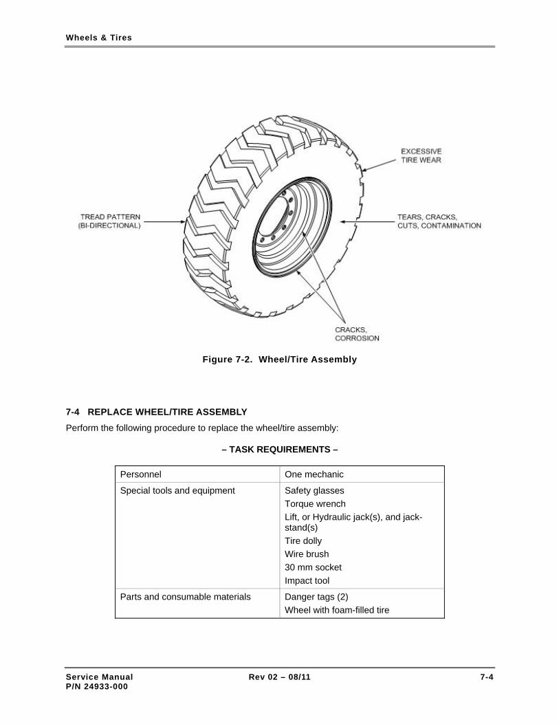
Wheels & Tires
Figure 7-2. Wheel/Tire Assembly
7-4 REPLACE WHEEL/TIRE ASSEMBLY
Perform the following procedure to replace the wheel/tire assembly:
– TASK REQUIREMENTS –
Personnel One mechanic
Special tools and equipment Safety glasses Torque wrench Lift, or Hydraulic jack(s), and jack-stand(s) Tire dolly Wire brush 30 mm socket Impact tool
Parts and consumable materials Danger tags (2) Wheel with foam-filled tire
Service Manual Rev 02 – 08/11 7-4 P/N 24933-000

Wheels & Tires
Support the weight of the forklift using a suitable lift, or jack(s) and jack stands with the appropriate load capacity. Forklift operating weights are listed below.
Table 7-1. Forklift Operating Weights
Forklift Model Operating Weight (Lbs.)
Forklift Model Operating Weight (Lbs.)
XR620 12,700 XR1270 47,300
XR621 12,700 XR1534 29,000
XR842 26,850 XR1642 41,000
XR1045 27,130 XR2034 40,140
XR1245 32,930 XR2045 44,750
XR1255 35,700 XR2450 48,750
XR1267 46,300 XR3034 47,850
INITIAL SET-UP
1. Park forklift on level surface.
2. Set Travel Select lever to NEUTRAL (N).
3. Set Parking Brake switch to ON.
4. Retract boom and lower carriage. Allow sufficient space to open forklift covers.
5. Set Ignition switch to OFF.
6. Attach danger tags to steering wheel and ignition key. Refer to para. 2-5, for lockout-tagout procedure.
REMOVAL
1. Raise forklift on lift or with jack(s) and support weight with jack stands.
2. Remove lug nuts with impact wrench with 30mm socket.
3. Remove wheel/tire assembly from wheel-end.
INSTALLATION
1. Clean wheel-end studs if dirty or corroded.
2. Clean area around wheel bolt holes if dirty or corroded.
3. Place wheel/tire assembly on wheel-end.
Service Manual Rev 02 – 08/11 7-5 P/N 24933-000

Wheels & Tires
4. To prevent cross-threading lug nuts, thread nuts on wheel-end studs by hand.
5. Using impact wrench and 30mm socket, tighten lug nuts. DO NOT over tighten nuts.
6. Torque lug nuts in accordance with instructions provided on Figure 7-3.
7. Lower forklift.
Figure 7-3. Wheel Lug Nut Tightening Sequence
Service Manual Rev 02 – 08/11 7-6 P/N 24933-000

Wheels & Tires
7-5 REPLACE TIRE
Mismatched tire sizes and ply ratings may compromise forklift stability. This may result in the forklift tipping over and causing death, serious injury, and property damage. Always replace tires with the proper size tires. Use only foam-filled tires. Tire and wheel assembly weight is critical to the stability of the forklift.
Xtreme Manufacturing recommends that tire removal and installation be performed only by authorized tire dealer/service centers. Ensure that the tires are replaced with the correct size and type and filled with the correct type of foam. Refer to Table 7-2 for detailed tire and foam specifications.
Table 7-2. Wheel and Tire Specifications
Item Specification
Wheels and Tires
Tire size and tread type XR620/621.……………………….12.0" X 16.5" E3 XR842/1045..……………………..13.0" X 24.0" E3 XR1245/1255/1534………………15.5" X 25.0" E3 XR1267/1270/1642/2034/2045…17.5" X 25.0" E3 XR2450/3034.........………………...16" X 25.0" E3
Gross weight of wheel and foam-filled tire XR620/621…………………………………..300 lbs. XR842/1045..………………………………..850 lbs. XR1245/1255/1534....………………………960 lbs. XR1267/1270/1642/2034/2045…………..1200 lbs. XR2450/3034..………………………….....1650 lbs.
Tire Foam
Material Polyurethane
Shore-A hardness (durometer) 28
Manufacturer and brand name Arnco RePneu® (or suitable substitute)
Service Manual Rev 02 – 08/11 7-7 P/N 24933-000

Wheels & Tires
Service Manual Rev 02 – 08/11 7-8 P/N 24933-000
THIS PAGE INTENTIONALLY LEFT BLANK

Hydraulic System
Section 8
Hydraulic System
8-1 GENERAL MAINTENANCE SAFETY
Use caution when performing maintenance on the forklift. Wear personal protective equipment when appropriate and use danger tags. Carefully follow the maintenance procedures provided in this chapter. Read the Material Safety Data Sheets (MSDS) for solvents, cleaners, etc. Read and fully understand the safety information provided in Chapter 2 – Maintenance & Operation Safety, before performing maintenance on the forklift.
8-2 HYDRAULICS MAINTENANCE SAFETY AND PRECAUTIONS
• Escaping hydraulic fluid under pressure can penetrate the skin, causing death or extremely serious injury. Amputation of hands and arms is often necessary to prevent death. Relieve hydraulic pressure before removing and installing any hydraulic system component.
• DO NOT use your hand or any part of your body to check for hydraulic leaks. When checking for hydraulic leaks, wear safety glasses and gloves to help provide protection from spraying hydraulic fluid. Use a piece of cardboard or paper to search for leaks.
• Hot hydraulic fluid can cause severe burns. Wait for hydraulic fluid to cool before performing maintenance on any hydraulic component.
Service Manual Rev 02 – 08/11 8-1 P/N 24933-000

Hydraulic System
• Spilled hydraulic fluid is a combustible and slip hazard material that requires immediate containment and cleaning. Failure to identify the spill, alert nearby personnel, and clean the spilled fluid may result in death or serious personal injury, and damage to equipment and facilities.
Very minute foreign particles, as small as 10 microns, can adversely affect operation of the hydraulic systems. (One micron equals one millionth of a meter.) Use extreme caution to prevent dirt, debris, and other contaminants from entering the hydraulic system.
8-3 HANDLING HYDRAULIC FLUID The following general precautions must be observed when handling hydraulic fluid:
• NEVER allow different categories of hydraulic fluids to become mixed. Chemical reactions may occur; fire resistant fluids may lose their fire resistance; and seals may be damaged.
• NEVER, under any circumstances, service the forklift with a fluid other than Dexron III (AW46 for older units with clear fluid).
• ENSURE that hydraulic fluid and fluid containers are protected from contamination of any kind. Dirt particles may cause hydraulic components to become inoperative, cause seal damage, etc. If there is any question regarding the cleanliness of the fluid, DO NOT use it. Containers for hydraulic fluid must never be left open to air longer than necessary.
• DO NOT expose hydraulic fluid to high temperature or open flames. Mineral-based fluids, such as Dexron III, are highly flammable.
8-4 MAKING LEAK-FREE CONNECTIONS
Some leakage in a hydraulic system is unavoidable. An example of this type of leakage would be the slight amount of fluid found on cylinder rods. However, any leakage reduces efficiency and causes power loss. Factors that contribute to leakage are:
• Hose and tubing installation practices.
• Operating conditions.
• Maintenance practices.
8-4-1 HOSE AND TUBING INSTALLATION PRACTICES
Installing hoses and tubing according to Xtreme Manufacturing maintenance instructions (Figure 8-1) will promote long life of external seals. Vibration or stresses that result from improper installation can shake loose connections. Avoid pinching, cocking, or incorrectly installing seals during hydraulic component installation.
8-4-2 OPERATING CONDITIONS
To ensure correct seal life, the operating conditions of the forklift must be controlled. A shaft seal or piston-rod seal exposed to moisture, salt, dirt, or any other abrasive contaminant will adversely affect a seal. Also, operators should always try to keep their loads within the recommended limits to prevent leakage caused by excessive pressures.
Service Manual Rev 02 – 08/11 8-2 P/N 24933-000

Hydraulic System
8-4-3 MAINTENANCE PRACTICES
Regular filter and hydraulic fluid changes, using high-quality Dexron III hydraulic fluid, adds to seal life. Using an inferior fluid will cause wear on seals and interfere with desirable hydraulic fluid properties. Proper maintenance prevents introduction of contaminants that can damage seals. Never use additives without approval from Xtreme Manufacturing. Manufacturers recommend soaking seals overnight in hydraulic fluid before installation. Do not install seals dry. Before installation, always coat seals with clean hydraulic fluid.
Figure 8-1. Making Leak-Free Connections
Service Manual Rev 02 – 08/11 8-3 P/N 24933-000

Hydraulic System
8-5 KEEPING THE HYDRAULIC SYSTEM CLEAN
The hydraulic system has been carefully designed to keep the hydraulic fluid free of contaminants. See Figure 8-2 for a schematic diagram of the hydraulic filtration system. The filtration system is comprised of the following components:
• Air breather (10 µM absolute).
• Suction strainer (200 µM).
• High-pressure filter (10 µM absolute).
• Return line filter (10 µM absolute).
Note that one micron (1 µM) is equal to one-millionth of a meter. Regardless of how thoroughly the system filters the fluid, it can easily be defeated by poor maintenance practices. To keep the hydraulic system free of contamination, it is essential that the following maintenance practices be followed:
• Clean exterior surfaces of dust, dirt, hydraulic fluid, etc. before removing covers.
• Ensure that new parts are clean before installation.
• Keep parts protected prior to assembly or installation.
• Protect system openings. Use covers, tape, plastic wrap, etc. to cover the openings.
• Keep fluid transfer containers, funnels, nozzles, etc. clean.
Service Manual Rev 02 – 08/11 8-4 P/N 24933-000

Hydraulic System
Figure 8-2. Hydraulic Filtration System
Service Manual Rev 02 – 08/11 8-5 P/N 24933-000

Hydraulic System
8-6 CHECK HYDRAULIC FLUID LEVEL
EVERY 8 HOURS OF OPERATION
Perform the following procedure to check the hydraulic fluid level and add fluid if required:
CHECK FLUID LEVEL
Check sight gauge on side of hydraulic reservoir (Figure 8-3). Fluid level should be at mid-point on gauge. If fluid level is low, refer to ADD FLUID procedure below.
ADD FLUID
– TASK REQUIREMENTS –
Personnel One mechanic
Special tools and equipment Safety glasses Hex key wrench, 3/4" Funnel
Parts and consumable materials Danger tags Hydraulic fluid, Dexron III (AW46 for older units with clear fluid) Safety solvent Brush Lint-free wiping cloths or clean cloth
INITIAL SET-UP
1. Park forklift on level surface.
2. Set Travel Select lever to NEUTRAL (N).
3. Set Parking Brake switch to ON.
4. Retract boom and lower carriage. Allow sufficient space to open forklift covers.
5. Set Ignition switch to OFF.
6. Attach danger tags to steering wheel and ignition key. Refer to para. 2-5, for lockout-tagout procedure.
7. Relieve hydraulic system pressure as follows:
a. Remove air breather from reservoir. Be careful to prevent contamination of air breather or reservoir fittings.
b. Depress pressure relief valve in center of reservoir air breather fitting.
Service Manual Rev 02 – 08/11 8-6 P/N 24933-000

Hydraulic System
Figure 8-3. Hydraulic Reservoir Sight Gauge
ADD FLUID – FILLER CAP
Contaminated hydraulic fluid can severely damage hydraulic system components and degrade performance. Ensure that filler cap and pipe are clean to prevent contaminants from entering reservoir when fluid is added to tank.
NOTE: Some early forklift models have lockable, filler caps used for adding hydraulic fluid. Late model forklifts have a plug installed in the filler/breather plate.
1. Inspect filler cap (Figure 8-4) and surrounding area for dirt and debris. Clean as required.
2. Unlock filler cap and lift cap.
3. Add fluid to reservoir until fluid level reaches midpoint on sight gauge.
4. Close and lock filler cap.
ADD FLUID – PLUG
1. Inspect plug (Figure 8-4) and surrounding area for dirt and debris. Clean as required.
2. Remove plug with adjustable wrench or 3/4" hex key wrench. Remove O-ring.
3. Add fluid to reservoir until fluid level reaches midpoint on sight gauge.
4. Install O-ring and plug in filler/breather plate and tighten.
Service Manual Rev 02 – 08/11 8-7 P/N 24933-000

Hydraulic System
Figure 8-4. Hydraulic Reservoir Fill Cap
8-7 CHANGE HYDRAULIC FLUID
EVERY 2,000 HOURS OF OPERATION
Perform the following procedure to change the hydraulic fluid:
– TASK REQUIREMENTS –
Personnel One mechanic
Special tools and equipment Safety glasses Containers (2) Funnel
Parts and consumable materials Danger tags (2) Hydraulic fluid, Dexron III (AW46 for older units with clear fluid) Safety solvent Brush Lint-free wiping cloths or clean cloth
NOTE: The strainer should be replaced or cleaned when the hydraulic fluid is changed. Refer to para. 8-8 for replacement procedure and para. 8-9 for cleaning procedure.
Service Manual Rev 02 – 08/11 8-8 P/N 24933-000

Hydraulic System
INITIAL SET-UP
1. Park forklift on level surface.
2. Set Travel Select lever to NEUTRAL (N).
3. Set Parking Brake switch to ON.
4. Retract boom and lower carriage. Allow sufficient space to open forklift covers.
5. Set Ignition switch to OFF.
6. Attach danger tags to steering wheel and ignition key. Refer to para. 2-5, for lockout-tagout procedure.
7. Relieve hydraulic system pressure as follows:
a. Remove air breather from reservoir. Be careful to prevent contamination of air breather or reservoir fittings.
b. Depress pressure relief valve in center of reservoir air breather fitting.
DRAIN AND FILL RESERVOIR
1. Place container under each drain plug (Figure 8-5).
2. Clean area around fill plug (Figure 8-4) on filler/breather plate.
3. Remove fill plug.
4. Clean area around each drain plug.
5. Remove both drain plugs from reservoir and allow hydraulic fluid to fill containers. When containers are full almost full, reinstall drain plugs.
6. Dispose of hydraulic fluid in accordance with state and/or local laws.
7. Repeat Steps 5 and 6 until reservoir and hydraulic system are fully drained.
8. Install both reservoir drain plugs and tighten.
9. Use clean funnel to add new hydraulic fluid to reservoir through fill port on filler/breather plate. Add fluid until fluid level reaches mid point on reservoir sight gauge (Figure 8-3).
10. Install fill cap on filler/breather plate and tighten.
11. Install air breather on filler/breather plate and tighten hand tight.
12. Start engine and check for leaks at both drain plugs, fill plug, and air breather.
NOTE: It is necessary to operate all hydraulic subsystems to expel any air bubbles entrained in the hydraulic fluid.
13. Use boom control to raise and extend boom. Then retract and lower boom.
14. Use sway control to tilt forklift to left, right, and back to level orientation.
15. Recheck reservoir fluid level sight gauge. Add more fluid as required using above procedure.
Service Manual Rev 02 – 08/11 8-9 P/N 24933-000

Hydraulic System
Figure 8-5. Hydraulic Reservoir
8-8 REPLACE SUCTION STRAINER
Perform the following procedure to replace the suction strainer
– TASK REQUIREMENTS –
Personnel One mechanic
Special tools and test equipment 2-3/4" open end wrench
Parts and consumable materials Danger tags Suction strainer Xtreme P/N 14365-000 Hydraulic fluid, Dexron III (AW46 for older units with clear fluid) Safety solvent Brush Lint-free wiping cloths or clean cloth Marker
Service Manual Rev 02 – 08/11 8-10 P/N 24933-000

Hydraulic System
INITIAL SET-UP
1. Park forklift on level surface.
2. Set Travel Select lever to NEUTRAL (N).
3. Set Parking Brake switch to ON.
4. Retract boom and lower carriage. Allow sufficient space to open forklift covers.
5. Set Ignition switch to OFF.
6. Attach danger tags to steering wheel and ignition key. Refer to para. 2-5, for lockout-tagout procedure.
7. Relieve hydraulic system pressure as follows:
a. Remove air breather from reservoir. Be careful to prevent contamination of air breather or reservoir fittings.
b. Depress pressure relief valve in center of reservoir air breather fitting.
REMOVAL
1. Drain reservoir (refer to para. 8-7).
2. To prevent contamination of reservoir, clean top of filler/breather plate (Figure 8-6) and adjacent area around reservoir opening.
3. Use marker to make orientation marks on filler/breather plate and top of reservoir.
4. Remove six screws and six flat washers from filler/breather plate.
5. Remove filler/breather plate from reservoir and place on clean, contaminant-free surface.
6. Use 2-3/4" open-end wrench to loosen strainer.
7. Remove strainer from reservoir.
INSTALLATION
1. Carefully mount strainer on fitting inside reservoir.
2. Tighten strainer slightly more than hand-tight with 2-3/4" open-end wrench.
3. Fill reservoir with hydraulic fluid (refer to para. 8-7).
4. Position filler/breather plate and O-ring on reservoir opening and align orientation marks.
5. Attach filler/breather plate to reservoir with six screws and six flat washers.
6. Start engine and check for leaks at filler/breather plate.
7. Check all hydraulic systems for proper operation.
8. Shut-off engine.
Service Manual Rev 02 – 08/11 8-11 P/N 24933-000

Hydraulic System
Figure 8-6. Hydraulic Reservoir Strainer
8-9 CLEAN HYDRAULIC RESERVOIR STRAINER
Perform the following procedure to clean the hydraulic reservoir strainer:
– TASK REQUIREMENTS –
Personnel One mechanic
Special tools and equipment Safety glasses 2-3/4" open-end wrench Container Gloves Brush
Service Manual Rev 02 – 08/11 8-12 P/N 24933-000

Hydraulic System
Parts and consumable materials Danger tags (2) Hydraulic fluid, Dexron III (AW46 for older units with clear fluid) Safety solvent Solvent Lint-free wiping cloths or clean cloth Marker
INITIAL SET-UP
1. Park forklift on level surface.
2. Set Travel Select lever to NEUTRAL (N).
3. Set Parking Brake switch to ON.
4. Retract boom and lower carriage. Allow sufficient space to open forklift covers.
5. Set Ignition switch to OFF.
6. Attach danger tags to steering wheel and ignition key. Refer to para. 2-5, for lockout-tagout procedure.
7. Relieve hydraulic system pressure as follows:
a. Remove air breather from reservoir. Be careful to prevent contamination of air breather or reservoir fittings.
b. Depress pressure relief valve in center of reservoir air breather fitting.
REMOVAL
1. Drain reservoir (refer to para. 8-7).
2. To prevent contamination of reservoir, clean top of filler/breather (Figure 8-6) and adjacent area around reservoir opening.
3. Use marker to make orientation marks on filler/breather plate and top of reservoir.
4. Remove six screws and six flat washers from filler/breather plate.
5. Remove filler/breather plate from reservoir and place on clean, contaminant-free surface.
6. Use 2-3/4" open-end wrench to loosen strainer.
7. Remove strainer from reservoir.
Be very careful to prevent dirt and other contaminants from entering the inside of the strainer.
DO NOT use compressed air to clean the strainer. Compressed air may damage filter media and force contaminants in to the filter media.
Service Manual Rev 02 – 08/11 8-13 P/N 24933-000

Hydraulic System
CLEANING
1. Inspect strainer for damage to threads. Inspect filter media for breaks and tears. Replace strainer if damaged.
2. Fill suitable, very clean, container, with fresh solvent.
3. Place strainer in solvent and clean with a clean, soft, bristle brush until all sludge, dirt, and residue have been removed from filter.
4. Remove strainer from solvent and rinse with hot soapy water until thoroughly clean. Then rinse with clean water.
5. Allow strainer to air dry.
INSTALLATION
1. Carefully mount strainer on fitting inside reservoir.
2. Tighten strainer slightly more than hand-tight with 2-3/4" open-end wrench.
3. Fill reservoir with hydraulic fluid (refer to para. 8-7).
4. Position filler/breather plate and O-ring on reservoir opening and align orientation marks.
5. Attach filler/breather plate to reservoir with six screws and six flat washers.
6. Start engine and check for leaks at filler/breather plate.
7. Check all hydraulic systems for proper operation.
8. Shut-off engine.
8-10 REPLACE AIR BREATHER
EVERY 500 HOURS OF OPERATION
Perform the following procedure to replace the air breather:
– TASK REQUIREMENTS –
Personnel One mechanic
Special tools and test equipment Safety glasses Strap wrench
Parts and consumable materials Air breather Xtreme P/N 14366-010 Safety solvent Lint-free wiping cloths or clean cloth Brush
Service Manual Rev 02 – 08/11 8-14 P/N 24933-000

Hydraulic System
INITIAL SET-UP
1. Park forklift on level surface.
2. Set Travel Select lever to NEUTRAL (N).
3. Set Parking Brake switch to ON.
4. Retract boom and lower carriage. Allow sufficient space to open forklift covers.
5. Set Ignition switch to OFF.
REPLACE AIR BREATHER
1. Carefully clean area around air breather fitting (Figure 8-7) to prevent contamination of reservoir.
2. Remove air breather from reservoir. If air breather cannot be removed by hand, loosen with a strap wrench.
3. Install new air breather on fitting and hand tighten. DO NOT use strap wrench to tighten filter.
4. Start engine and check for leaks at air breather.
5. Check operation of hydraulic system.
Figure 8-7. Air Breather
Service Manual Rev 02 – 08/11 8-15 P/N 24933-000

Hydraulic System
8-11 REPLACE HIGH-PRESSURE FILTER
EVERY 1,000 HOURS OF OPERATION
Perform the following procedure to replace the high-pressure filter:
– TASK REQUIREMENTS –
Personnel One mechanic
Special tools and equipment Safety glasses Wheel chocks (4) O-ring removal/installation tool Container
Parts and consumable materials Danger tags (2) High-pressure filter element P/N 14360-000 O-ring seal kit, Xtreme P/N 14359-000 Chip indicator, Xtreme P/N 14359-010 Hydraulic fluid, Dexron III (AW46 for older units with clear fluid) Safety solvent Lint-free cloths or clean cloth Brush
INITIAL SET-UP
1. Park forklift on level surface.
2. Set Travel Select lever to NEUTRAL (N).
3. Set Parking Brake switch to ON.
4. Retract boom and lower carriage. Allow sufficient space to open forklift covers.
5. Set Ignition switch to OFF.
6. Attach danger tags to steering wheel and ignition key. Refer to para. 2-5, for lockout-tagout procedure.
7. Place wheel chocks in front of front tires and behind rear tires.
DO NOT relieve hydraulic system pressure by loosening plugs located at top and bottom of high-pressure filter. See Figure 8-9 for location of plugs.
Service Manual Rev 02 – 08/11 8-16 P/N 24933-000

Hydraulic System
8. Relieve hydraulic system pressure as follows:
a. Remove air breather from reservoir. Be careful to prevent contamination of air breather or reservoir fittings.
b. Depress pressure relief valve in center of reservoir air breather fitting.
REPLACE FILTER
1. Open front cover (Figure 1-2) to gain access to high-pressure filter (Figure 8-8).
2. Inspect chip indicator (Figure 8-9) if installed. Replace as required.
3. Place container beneath filter.
Figure 8-8. Location of Hydraulic Filters
Filter bowl may be full of hot hydraulic fluid.
Service Manual Rev 02 – 08/11 8-17 P/N 24933-000

Hydraulic System
4. Use wrench to remove filter bowl from filter body. Allow hydraulic fluid to drain into container.
5. Remove filter element from filter bowl and dispose of properly.
6. Coat new filter bowl O-ring with hydraulic fluid and install in filter bowl.
7. Coat new filter head seal with hydraulic fluid and install in filter head.
8. Insert new filter element inside filter bowl.
Special care is required when screwing filter bowl into filter to prevent cross threading. DO NOT torque the filter bowl. Hand tighten only.
9. Screw filter bowl onto filter head until O-ring contacts sealing surface, then tighten 3/4 turn.
10. Start engine and run until warm.
11. Check for leaks at filter. Hand tighten filter further if necessary.
Figure 8-9. High-Pressure Filter
Service Manual Rev 02 – 08/11 8-18 P/N 24933-000

Hydraulic System
8-12 REPLACE RETURN LINE FILTER
AFTER FIRST 50 HOURS AND EVERY 500 HOURS OF OPERATION
Perform the following procedure to replace the return line filter:
– TASK REQUIREMENTS –
Personnel One mechanic
Special tools and equipment Safety glasses Wheel chocks (4) Filter wrench or strap wrench O-ring removal/installation tool Container
Parts and consumable materials Danger tags (2) Return line filter Xtreme P/N 14361-000 O-ring Seal Hydraulic fluid, Dexron III (AW46 for older units with clear fluid) Safety solvent Lint-free cloths or clean cloth Brush
INITIAL SET-UP
1. Park forklift on level surface. 2. Set Travel Select lever to NEUTRAL (N). 3. Set Parking Brake switch to ON. 4. Retract boom and lower carriage. Allow sufficient space to open forklift covers. 5. Set Ignition switch to OFF. 6. Attach danger tags to steering wheel and ignition key. Refer to para. 2-5, for lockout-tagout
procedure. 7. Place wheel chocks in front of front tires and behind rear tires.
8. Relieve hydraulic system pressure as follows: a. Remove air breather from reservoir. Be careful to prevent contamination of air breather or
reservoir fittings. b. Depress pressure relief valve in center of reservoir air breather fitting.
Service Manual Rev 02 – 08/11 8-19 P/N 24933-000

Hydraulic System
REPLACE FILTER
1. Open front cover (Figure 1-2) to gain access to return line filter (Figure 8-8). 2. Place container beneath return line filter. 3. Clean area around filter to prevent contaminants from entering system.
Filter may be full of hot hydraulic fluid.
4. Use strap wrench or filter wrench to remove filter from distribution manifold (Figure 8-10). Allow hydraulic fluid to drain into container.
5. Dispose of fluid and filter properly.
6. Lubricate new O-ring with hydraulic fluid and install on filter.
DO NOT torque the filter. Hand tighten only.
7. Screw filter on to distribution manifold and hand tighten until O-ring contacts sealing surface, then tighten 3/4 turn.
8. Start engine and run until warm. 9. Check for leaks at filter. Hand tighten filter further if necessary.
Figure 8-10. Return Line Filter
Service Manual Rev 02 – 08/11 8-20 P/N 24933-000

Hydraulic System
8-13 TAKING HYDRAULIC FLUID SAMPLE
Perform the following procedure to take a hydraulic fluid sample.
– TASK REQUIREMENTS –
Personnel One mechanic
Special tools and equipment Safety glasses Rubber gloves Soft bristle brush HYDAC Micro Bore Flexible Hose
Parts and consumable materials Danger tags (2) Safety solvent (aerosol) Lint-free cloth Fluid analysis kit
INITIAL SET-UP
1. Park forklift on level surface.
2. Set Travel Select lever to NEUTRAL (N).
3. Set Parking Brake switch to ON.
4. Retract boom and lower carriage. Allow sufficient space to open forklift covers.
5. Operate engine at idle speed.
6. Attach DANGER – DO NOT OPERATE tag to steering wheel. Also attach a tag by tape or cord around the boom control, attachment tilt, and frame sway joysticks. Operating any one of these joysticks can raise the pressure at the distribution manifold test port from 500 psi to 3,500 psi.
TAKING SAMPLE
1. Put on safety glasses and rubber gloves.
2. Open front cover to gain access to distribution manifold.
3. On back side of distribution manifold (Figure 8-11), remove cap from test port GLS.
4. Thoroughly clean area around test port GLS with clean brush, safety solvent, and clean, lint-free cloth.
Be very careful to keep the test hose and the fluid sample bottle clean during this procedure. Very minute foreign particles can contaminate the sample and adversely affect the test results.
5. Check test hose and fluid sample bottle to ensure that they are very clean.
Service Manual Rev 02 – 08/11 8-21 P/N 24933-000

Hydraulic System
Hydraulic fluid under pressure can penetrate the skin, causing death or extremely serious injury. Amputation of hands and arms is often necessary to prevent death.
If this procedure is followed correctly, the maximum pressure available at test port GLS is 500 psi. The pressure will be much less simply by connecting the test hose to the port slowly until sufficient flow is obtained to fill the fluid sample bottle.
DO NOT operate the boom control, attachment tilt, or frame sway joysticks during this procedure. If any of these joysticks are operated, the pressure at test port GLS can increase to 3,500 psi thereby creating an extremely hazardous situation.
6. In one hand, hold fluid sample bottle upright with one end of test hose secured at opening of bottle with thumb and forefinger.
7. With other hand's thumb and forefinger, very slowly screw other end of test hose into test port GLS until fluid begins to flow into fluid sample bottle.
8. Fluid flow rate is controlled by how far hose connector is screwed on to test port GLS. Unscrew hose connector from test port when bottle is almost full.
9. Place cap on fluid sample bottle and tighten.
10. Remove test hose from test port GLS and reconnect cap.
11. Clean any spilled hydraulic fluid.
12. Close front cover.
Service Manual Rev 02 – 08/11 8-22 P/N 24933-000

Hydraulic System
Figure 8-11. Taking Hydraulic Fluid Sample
Service Manual Rev 02 – 08/11 8-23 P/N 24933-000
Hydraulic System
8-14 REPLACING A HOSE
Perform the following procedure to replace a hydraulic hose:
– TASK REQUIREMENTS –
Personnel One mechanic
Special tools and equipment Safety glasses Torque wrench O-ring removal/installation tool Brush Container
Parts and consumable materials Danger tags (2) Protective caps, plugs Safety solvent Lint-free cloth
NEVER replace a hydraulic hose with a hose not specifically designed for this forklift and subsystem. An underrated hose may explode resulting in death or serious injury and damage to the forklift and property. Always use genuine Xtreme Manufacturing replacement hoses for best performance and safety.
INITIAL SET-UP
1. Park forklift on level surface.
2. Set Travel Select lever to NEUTRAL (N).
3. Set Parking Brake switch to ON.
4. Retract boom and lower carriage. Allow sufficient space to open forklift covers.
5. Set Ignition switch to OFF.
6. Attach danger tags to steering wheel and ignition key. Refer to para. 2-5, for lockout-tagout procedure.
7. Relieve hydraulic system pressure as follows:
a. Remove air breather from reservoir. Be careful to prevent contamination of air breather or reservoir fittings.
b. Depress pressure relief valve in center of reservoir air breather fitting.
REMOVAL
1. Open front cover (Figure 1-2).
Service Manual Rev 02 – 08/11 8-24 P/N 24933-000

Hydraulic System
2. Check hose or hoses to be replaced by twisting or squeezing them to see if pressure has been relieved. If pressure is still in the hose or hoses, take appropriate measures to relieve the pressure before loosening the fittings.
3. To prevent contamination of hydraulic system, ensure that hose and component fittings and adjacent area are clean. Clean as required with safety solvent, brush, and lint-free cloths.
4. Place suitable container beneath hose and component fitting to catch oil that drains from hose and component.
5. Disconnect hose from hydraulic component fitting.
6. Drain hydraulic fluid from hose end into container.
7. If hose is not to be immediately replaced, place protective cap on component fitting.
8. Repeat Step 3 through Step 7 for connector at opposite end of hose.
9. Remove hose from forklift.
INSTALLATION
1. Verify that replacement hose part number is same as part number on defective hose.
2. Remove protective caps from replacement hose fittings. Inspect fittings for damage and cleanliness.
3. Inspect replacement hose for nicks, cuts, or other damage.
4. If replacement hose interior and/or fittings are dirty, clean by flushing with hydraulic fluid.
5. Carefully inspect component fittings for damage and cleanliness. Fittings can be reused if clean and serviceable.
6. Replace component fitting O-rings using O-ring removal/installation tool. DO NOT reuse O-rings.
7. Carefully connect hose connector to one component fitting and hand-tighten. Ensure hose connector is not cross-threaded.
8. Route hose in same location/path as removed hose. See Figure 8-12 for hose installation guidelines.
9. Verify that hose has sufficient slack and bend radius. Verify that hose is not twisted and that it will not interfere with any moving forklift parts.)
10. Carefully connect opposite end hose connector to other component fitting. Tighten connecter.
11. Torque both hose connectors. Refer to Table 8-1 for hose connector torque values.
12. Re-install and/or tighten any hose clamps that were removed or loosened during hose removal.
Before starting the engine, verify that all hydraulic connections are properly tightened. Escaping hydraulic fluid under pressure can penetrate the skin, causing death or extremely serious injury
13. Start engine and check for leaks and operation of affected system.
14. Check hydraulic fluid level (para. 8-6). Add fluid as required.
Service Manual Rev 02 – 08/11 8-25 P/N 24933-000

Hydraulic System
Figure 8-12. Hose Installation Guidelines
Service Manual Rev 02 – 08/11 8-26 P/N 24933-000

Hydraulic System
Table 8-1. Hose Connector Torque Values
Dash Size Thread Size (Inches)
Swivel Nut Torque (Ft-Lbs.)
–04 9/16 -18 10-12
–06 11/16 -16 18-20
–08 13/16 -16 32-35
–10 1-14 46-50
–12 13/16 -12 65-70
–16 17/16 -12 92-100
–20 111/16 -12 125-140
–24 2-12 150-165
8-15 TIGHTENING LOOSE FITTINGS
If a hydraulic connection is leaking, DO NOT tighten the fitting while the engine is operating and the hydraulic system is pressurized. Death or extremely serious injury may result if a fitting, tube, hose, or component ruptures while pressurized.
8-16 REPLACE CARTRIDGE VALVE
Perform the following procedure to replace a cartridge valve:
– TASK REQUIREMENTS –
Personnel One mechanic
Special tools and equipment Safety glasses Rubber gloves Torque wrench Thread chaser Clean container
Service Manual Rev 02 – 08/11 8-27 P/N 24933-000

Hydraulic System
Parts and consumable materials Danger tags (2) Cartridge valve Hydraulic fluid, Dexron III (AW46 for older units with clear fluid) Safety solvent Brush Clean shop rags Lint-free wiping cloths
INITIAL SET-UP
1. Park forklift on level surface.
2. Set Travel Select lever to NEUTRAL (N).
3. Set Parking Brake switch to ON.
4. Retract boom and lower carriage. Allow sufficient space to open forklift covers.
5. Set Ignition switch to OFF.
6. Attach danger tags to steering wheel and ignition key. Refer to para. 2-5, for lockout-tagout procedure.
7. Relieve hydraulic system pressure as follows:
a. Remove air breather from reservoir. Be careful to prevent contamination of air breather or reservoir fittings.
b. Depress pressure relief valve in center of reservoir air breather fitting.
c. If cartridge valve is installed in a boom lift cylinder, turn manual lowering valve adjustment screw (Figure 10-13) fully counterclockwise (CCW) approximately five turns.
d. If cartridge valve is installed in the boom extend cylinder, turn manual lowering valve adjustment screw (Figure 10-13) fully counterclockwise (CCW) approximately five turns.
REMOVAL
1. Gain access to cartridge valve.
2. If valve is solenoid-type, refer to para. 8-17 for solenoid removal instructions.
3. Use safety solvent, brush, and lint-free wipes to thoroughly clean cartridge valve and surrounding area.
Service Manual Rev 02 – 08/11 8-28 P/N 24933-000

Hydraulic System
There may be residual pressure in the hydraulic system after performing steps 7a through 7d. Wear eye protection and gloves. Loosen the valve slowly and be ready for a momentary release of pressurized hydraulic fluid.
4. Wrap several shop rags around valve to absorb escaping, spraying oil and prevent injury to mechanic.
5. Very slowly loosen valve and remove from component.
6. If necessary, clean area around valve port again in the event area became re-contaminated during valve removal.
7. Carefully inspect port thread for burrs or other irregularities. Repair damaged threads with thread chaser.
INSTALLATION
Installation of a cartridge valve in the incorrect manifold or cylinder block port can cause serious injury or death and damage to equipment.
Installation of an incorrect cartridge valve in a manifold or cylinder block can cause serious injury or death and damage to equipment.
When replacing a cartridge valve, check that the numbers and/or letters on the old cartridge valve exactly match the numbers and/or letters on the new cartridge valve. If there is a discrepancy in a single letter or number, DO NOT install the cartridge valve. Call the supplier/manufacturer for assistance.
The fact that a replacement cartridge valve fits into a manifold or valve block correctly is no indication that the cartridge valve is the correct model/part number
Hydraulic component manufacturers do not follow any standardized method of identifying (labeling) ports, etc. For example, do not assume that the number 1 always corresponds to the inlet port, etc.
1. Inspect exterior of new valve for dirt and contaminants.
2. Ensure that O-rings and back-up rings are intact and correctly positioned.
3. If valve is equipped with solenoid, refer to para. 8-17 for removal instructions.
4. Inspect valve cavity in manifold for burrs or other defects which could damage O-rings and back-up rings during installation.
5. If cavity threads are damaged, try cleaning the threads using a thread chaser. Ensure that the correct size thread chaser is used and that no metal particles are allowed to fall inside the manifold cavity.
6. Dip valve in clean oil.
7. Screw valve in by hand until top O-ring is met. Then tighten valve by torque wrench to the torque specification provided by the manufacturer.
8. If valve is equipped with a solenoid, refer to para. 8-17 for installation instructions.
Service Manual Rev 02 – 08/11 8-29 P/N 24933-000

Hydraulic System
9. If a boom lift or extend cylinder manual lowering valve was opened, close valve by turning the adjustment screw five turns clockwise (CW).
10. Start engine and check operation of applicable hydraulic subsystem.
Counterbalance valves are factory set. DO NOT adjust.
8-17 REPLACE CARTRIDGE VALVE SOLENOID
Perform the following procedure to replace a cartridge valve solenoid:
– TASK REQUIREMENTS –
Personnel One mechanic
Special tools and equipment Safety glasses
Parts and consumable materials Danger tags (2) Solenoid
INITIAL SET-UP
1. Park forklift on level surface. 2. Set Travel Select lever to NEUTRAL (N). 3. Set Parking Brake switch to ON. 4. Retract boom and lower carriage. Allow sufficient space to open forklift covers. 5. Set Ignition switch to OFF. 6. Attach danger tags to steering wheel and ignition key. Refer to para. 2-5, for lockout-tagout
procedure. 7. Relieve hydraulic system pressure as follows:
a. Remove air breather from reservoir. Be careful to prevent contamination of air breather or reservoir fittings.
b. Depress pressure relief valve in center of reservoir air breather fitting.
REPLACE SOLENOID
1. Disconnect solenoid connector (Figure 8-13) from chassis wiring harness connector. 2. Turn nut on top of solenoid counterclockwise (CCW) to loosen. 3. Remove nut from solenoid body. 4. Lift solenoid off of valve body. 5. Place new solenoid on valve body.
Service Manual Rev 02 – 08/11 8-30 P/N 24933-000

Hydraulic System
DO NOT over tighten nut. Damage to valve will result.
6. Install nut on solenoid body and turn clockwise (CW) to tighten. Torque nut to 3-4.5 ft-lbs. 7. Connect solenoid connector to chassis wiring harness connector. 8. Start engine and check operation of applicable hydraulic subsystem.
Figure 8-13. Cartridge Valve Solenoid
Service Manual Rev 02 – 08/11 8-31 P/N 24933-000

Hydraulic System
8-18 LOCATION OF HYDRAULIC COMPONENTS
The location of several major hydraulic components and close-up views are provided in Figure 8-14. The torque values for the valves depicted in Figure 8-14 are provided in Tables 8-2 through 8-5.
8-19 DISTRIBUTION MANIFOLD HOSE CONNECTIONS
See Figures 8-15 through 8-18 for diagrams depicting the distribution manifolds and the part numbers of hoses connected to the various manifold ports.
Figure 8-14. Location of Hydraulic Components (Sheet 1 of 5)
Service Manual Rev 02 – 08/11 8-32 P/N 24933-000

Hydraulic System
Figure 8-14. Location of Hydraulic Components (Sheet 2 of 5)
Service Manual Rev 02 – 08/11 8-33 P/N 24933-000

Hydraulic System
Figure 8-14. Location of Hydraulic Components (Sheet 3 of 5)
Service Manual Rev 02 – 08/11 8-34 P/N 24933-000

Hydraulic System
Figure 8-14. Location of Hydraulic Components (Sheet 4 of 5)
Service Manual Rev 02 – 08/11 8-35 P/N 24933-000

Hydraulic System
Figure 8-14. Location of Hydraulic Components (Sheet 5 of 5)
Service Manual Rev 02 – 08/11 8-36 P/N 24933-000

Hydraulic System
Figure 8-15. Distribution Manifold Hose Connections – Model XR842 (Sheet 1 of 2)
Service Manual Rev 02 – 08/11 8-37 P/N 24933-000

Hydraulic System
Figure 8-15. Distribution Manifold Hose Connections – Model XR842 (Sheet 2 of 2)
Service Manual Rev 02 – 08/11 8-38 P/N 24933-000

Hydraulic System
Figure 8-16. Distribution Manifold Hose Connections – Model XR1045 (Sheet 1 of 2)
Service Manual Rev 02 – 08/11 8-39 P/N 24933-000

Hydraulic System
Figure 8-16. Distribution Manifold Hose Connections – Model XR1045 (Sheet 2 of 2)
Service Manual Rev 02 – 08/11 8-40 P/N 24933-000

Hydraulic System
Figure 8-17. Distribution Manifold Hose Connections – Model XR1245 (Sheet 1 of 2)
Service Manual Rev 02 – 08/11 8-41 P/N 24933-000

Hydraulic System
Figure 8-17. Distribution Manifold Hose Connections – Model XR1245 (Sheet 2 of 2)
Service Manual Rev 02 – 08/11 8-42 P/N 24933-000

Hydraulic System
Figure 8-18. Distribution Manifold Hose Connections – Model XR1255 (Sheet 1 of 2)
Service Manual Rev 02 – 08/11 8-43 P/N 24933-000

Hydraulic System
Figure 8-18. Distribution Manifold Hose Connections – Model XR1255 (Sheet 2 of 2)
Service Manual Rev 02 – 08/11 8-44 P/N 24933-000

Hydraulic System
Table 8-2. Boom Isolation Manifold Valve Torque Values
Component Component No. Torque Value (ft-lbs)
Pilot-to-open check valve 2.1 25-30
Pilot-to-open check valve 2.2 25-30
Pressure reducing/relieving valve 5 29-37
Needle valve 1 29-37
Check valve 7 59-66
Pressure relief valve 6 19-22
Diverter valve 4 37
Shuttle valve 3 11-13
Table 8-3. Rear Axle Cylinder Valve Torque Values
Component Component No. Torque Value (ft-lbs)
Bypass valve 1 67-74
Float valve 4 18.5-22
Table 8-4. Distribution Manifold Torque Values (XR842/1045)
Component Component No. Torque Value (ft-lbs)
Park brake release pressure reducing valve 8 18.5-22
Rear lock system pressure reducing valve 9 18.5-22
Steering mode valve 1 28-33
Service Manual Rev 02 – 08/11 8-45 P/N 24933-000

Hydraulic System
Table 8-4. Distribution Manifold Torque Values (XR842/1045) – Cont.
Component Component No. Torque Value (ft-lbs)
Left frame lockout valve 10.1 18.5-22
Main frame level lockout valve 4 18.5-22
Load sense dump valve 12 18.5-22
Right frame level lockout valve 10.2 18.5-22
Steering mode valve 1 28-33
Park brake release valve 7 18.5-22
Table 8-5. Distribution Manifold Torque Values (XR1245/1255)
Component Component No. Torque Value (ft-lbs)
Park brake release pressure reducing valve 8 18.5-22
Rear axle lock system pressure reducing valve 9 18.5-22
Left frame lockout valve 10.1 18.5-22
Main frame level lockout valve 4 18.5-22
Steering mode valve 2 28-33
Left outrigger up valve 19.1 –
Load sense dump valve 12 18.5-22
Right outrigger up valve 19.2 –
Right outrigger down valve 19.2 –
Left outrigger down valve 19.1 –
Steering mode valve 2 28-33
Right frame level lockout valve 10.2 18.5-22
Park brake release valve 13 18.5-22
Service Manual Rev 02 – 08/11 8-46 P/N 24933-000

Hydraulic System
8-20 MAINTENANCE REQUIREMENTS FOR FAILED PUMP
If the hydraulic pump should fail, the hydraulic fluid will very likely be contaminated with metal particles and other types of contaminants. In addition to replacing the pump, the following maintenance actions should be taken:
• Drain the reservoir.
• Clean or replace the hydraulic reservoir strainer.
• Fill the reservoir with clean, filtered hydraulic fluid.
• Replace the high-pressure filter.
• Replace the return line filter.
• Operate all hydraulic systems through ten cycles of operation.
• If any subsystem fails or has degraded performance, the components of that system should be removed from the forklift, disassembled, and thoroughly cleaned.
• Remove the return line filter. Inspect the filter and hydraulic fluid for contamination.
If the hydraulic fluid is still contaminated, perform the following maintenance actions:
• Drain the reservoir.
• Clean or replace the hydraulic reservoir strainer.
• Fill the reservoir with clean, filtered hydraulic fluid.
• Replace the high-pressure filter.
• Replace the return line filter.
• Operate all hydraulic systems through ten cycles of operation.
• If any subsystem fails or has degraded performance, the components of that system should be removed from the forklift, disassembled, and thoroughly cleaned.
• Take a sample of the hydraulic fluid and have it analyzed. Perform additional maintenance per recommendations provided in the hydraulic fluid analysis report.
Service Manual Rev 02 – 08/11 8-47 P/N 24933-000

Hydraulic System
Service Manual Rev 02 – 08/11 8-48 P/N 24933-000
THIS PAGE INTENTIONALLY LEFT BLANK

Electrical System
Section 9
Electrical System
9-1 GENERAL MAINTENANCE SAFETY
Use caution when performing maintenance on the forklift. Wear personal protective equipment when appropriate and use danger tags. Carefully follow the maintenance procedures provided in this chapter. Read the Material Safety Data Sheets (MSDS) for solvents, cleaners, etc. Read and fully understand the safety information provided in Chapter 2 – Maintenance & Operation Safety, before performing maintenance on the forklift.
9-2 BATTERY SAFETY
• If contact with battery acid occurs, administer the following first aid treatment to self or others:
– External contact – Flush with water. – Eyes – Flush with water for at least 15 minutes. Get medical attention
immediately. – Internal contact – Drink large quantities of water. Follow with Milk of
Magnesia, beaten egg, or vegetable oil. Get medical attention immediately.
– IMPORTANT – In case of internal contact, DO NOT give fluids that induce vomiting.
• Disconnect the battery terminals before a repair is made to the electrical system.
Service Manual Rev 02 – 08/11 9-1 P/N 24933-000
Electrical System
• Lead-acid batteries produce flammable and potentially explosive gases. To avoid injury or death when checking, testing, or charging batteries:
– DO NOT use smoking materials near batteries. – Keep arcs, sparks, and open flames away from batteries. – Provide ventilation for flammable vapors. – Wear proper personal protective equipment, including safety glasses.
• Fluid in electric storage batteries contains sulfuric acid which is a poison that can cause severe chemical burns. Avoid all contact of fluid with eyes, skin, or clothing. Use protective gear when handling batteries.
• DO NOT tip a battery beyond a 45° angle in any direction. • Wear eye protection when starting a vehicle with jump start cables. Improper
jump start procedures can cause the battery to explode. • Do not allow sparks or fire near the batteries (especially when the batteries are
on charge) because the gases from the electrolyte are highly flammable. The battery fluid is dangerous to the skin and especially to the eyes.
• NEVER jump start a frozen battery, as it can explode. Let the battery thaw out before charging.
• NEVER jump start the forklift directly at the starter solenoid. This could cause the vehicle to lurch forward or backward, resulting in injury or death.
• To avoid injury or death when jump starting with another vehicle, ensure the two vehicles are not touching.
• DO NOT allow jump start cable ends to contact each other near the battery.
• Connect charged battery positive (+) to stalled battery positive (+).
• Connect charged battery negative (–) to stalled vehicle ground. Make the connection to the stalled vehicle ground LAST.
• Connect jump start cable to stalled vehicle ground a safe distance from the battery to PREVENT sparks near the battery.
• Jump start only with a power source with the same voltage as the stalled forklift.
• Jump start power source must have a negative-ground electrical system.
• Electrolyte is an acid and cause injury if it contacts the skin or eyes.
CALIFORNIA PROPOSITION 65
Battery posts, terminals, and related accessories contain lead and lead compounds, chemicals known to the State of California to cause cancer and birth defects or other reproductive harm. WASH HANDS IMMEDIATELY AFTER HANDLING BATTERY.
Service Manual Rev 02 – 08/11 9-2 P/N 24933-000

Electrical System
9-3 BATTERY DESCRIPTION
The forklift's initial source of electricity is the 12-volt battery. The primary function of the battery is to start the engine. Once the engine is running, the alternator takes over to supply the forklift's electrical requirements and to charge the battery.
The battery consists of layers of positively and negatively charged lead plates that, together with their insulated separators, make up each of six, two-volt cells. The cells are filled with an electricity-conducting liquid (electrolyte). The electrolyte contains approximately two-thirds distilled water and one-third sulfuric acid. Spaces between the immersed plates provide the most exposure to the electrolyte. The interaction of the plates and the electrolyte produces chemical energy that becomes electricity when a circuit is formed between the negative and positive battery terminals.
9-4 BATTERY CABLE DESCRIPTION
The battery cables connect the battery to the starting and charging circuits. Because of the heavy current flow through the cables, the cables are fabricated from size 1 AWG cable. The red cable is connected to the positive terminal of the battery and the black lead is connected to the negative terminal.
Because of the cable's close proximity to the battery it is extremely important to periodically inspect and clean the cables, clamps, and battery posts. Vapors from battery acid causes corrosion to form on the lead surfaces and copper wiring associated with the battery wires. A loose or corroded connection will cause a significant voltage drop. This voltage drop will cause the starter motor to turn slowly or not at all.
9-5 CHECK CONDITION OF BATTERY AND CABLES
EVERY 8 HOURS OF OPERATION
Perform the following procedure to check the condition of the battery and cables:
– TASK REQUIREMENTS –
Personnel One mechanic
Special tools and equipment Safety glasses Rubber gloves
Parts and consumable materials None
INITIAL SET-UP
1. Park forklift on level surface.
2. Set Travel Select lever to NEUTRAL (N).
3. Set Parking Brake switch to ON.
4. Retract boom and lower carriage. Allow sufficient space to open forklift covers.
5. Set Ignition switch to OFF.
CHECK BATTERY AND CABLES
1. Pull back on both battery cover T-handles until they release from holders (Figure 1-2).
Service Manual Rev 02 – 08/11 9-3 P/N 24933-000

Electrical System
2. Lower battery compartment cover.
3. Check battery condition indicator by looking straight down at indicator. Indicator will appear green if battery is fully charged. If battery charge is depleted, indicator will appear black. If indicator appears black, charge or replace battery. If indicator appears white, replace the battery. DO NOT attempt to test or charge the battery.
4. Check battery cables and terminal for tightness and corrosion. Tighten and clean as required
5. Close battery compartment cover.
Figure 9-1. Battery and Cables
9-6 REPLACE BATTERY
Perform the following procedure to replace the battery:
– TASK REQUIREMENTS –
Personnel One mechanic
Special tools and equipment Safety glasses Rubber gloves Rubber apron Battery post/terminal cleaning tool
Service Manual Rev 02 – 08/11 9-4 P/N 24933-000

Electrical System
Parts and consumable materials Danger tags (2) Battery Paper towels Battery post/terminal grease
DO NOT begin this maintenance procedure without first reading and understanding para. 9-2, Battery Safety.
INITIAL SET-UP
1. Park forklift on level surface. 2. Set Travel Select lever to NEUTRAL (N). 3. Set Parking Brake switch to ON. 4. Retract boom and lower carriage. Allow sufficient space to open forklift covers. 5. Set Ignition switch to OFF. 6. Attach danger tags to steering wheel and ignition key. Refer to para. 2-5, for lockout-tagout
procedure.
REMOVAL
1. Pull back on both battery cover T-handles until they release from holders (Figure 1-2).
2. Lower battery cover. 3. Disconnect positive (red) battery cable terminal (Figure 9-1) from positive post (+) of battery. 4. Disconnect negative (black) battery cable terminal from negative (-) post of battery. 5. Loosen wing nuts on both j-bolts (Figure 9-2) until they can be removed from slots in recessed battery
mount. 6. Remove battery from forklift.
INSTALLATION
1. Place new battery in mount. 2. Insert curved end of J-bolts in mount holes. 3. Position battery hold-down on top of battery and over J-bolts and attach with wing nuts. 4. Inspect cable terminals for cleanliness and corrosion. Clean as required with a battery post/terminal
cleaning tool. 5. Apply battery terminal grease to both battery posts.
Service Manual Rev 02 – 08/11 9-5 P/N 24933-000
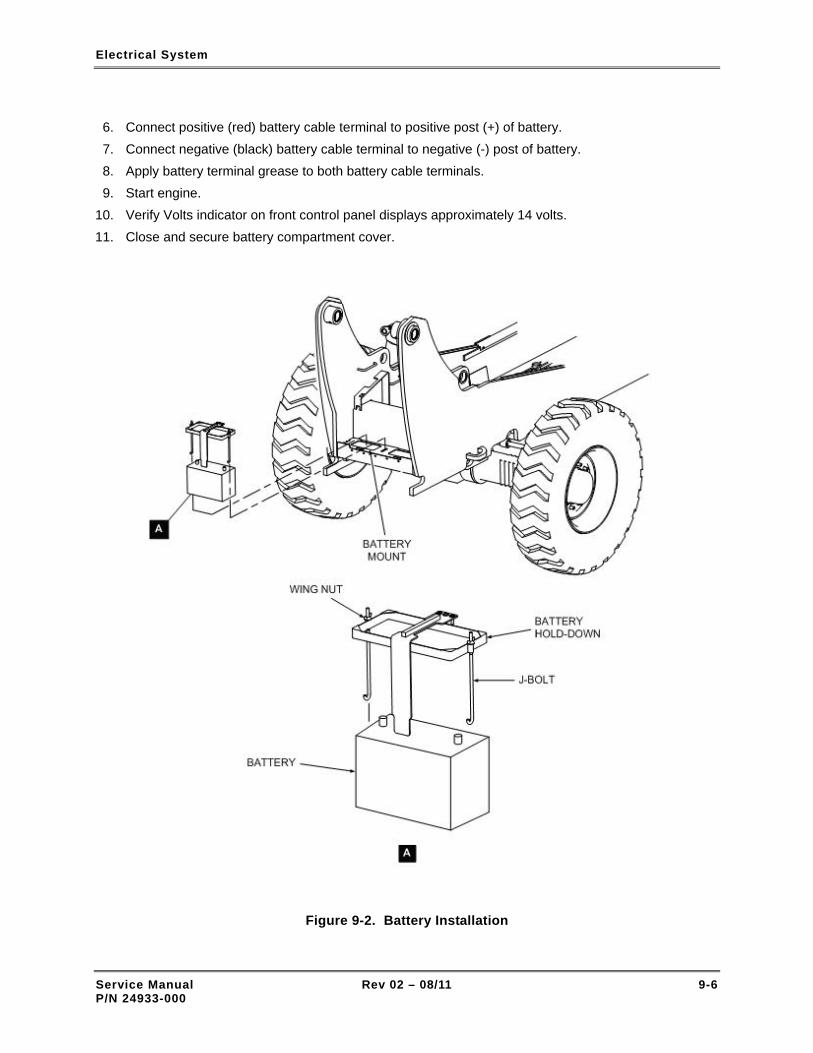
Electrical System
6. Connect positive (red) battery cable terminal to positive post (+) of battery. 7. Connect negative (black) battery cable terminal to negative (-) post of battery. 8. Apply battery terminal grease to both battery cable terminals. 9. Start engine.
10. Verify Volts indicator on front control panel displays approximately 14 volts. 11. Close and secure battery compartment cover.
Figure 9-2. Battery Installation
Service Manual Rev 02 – 08/11 9-6 P/N 24933-000

Electrical System
9-7 INSPECT AND CLEAN BATTERY
Perform the following procedure to inspect and clean the battery:
– TASK REQUIREMENTS –
Personnel One mechanic
Special tools and equipment Safety glasses Rubber gloves Stiff bristle brush Container
Parts and consumable materials Baking soda (1 tabs) Warm water (8 oz) Spray detergent Spay solvent Paper towels
DO NOT begin this maintenance procedure without first reading and understanding para. 9-2, Battery Safety.
INITIAL SET-UP
1. Park forklift on level surface.
2. Set Travel Select lever to NEUTRAL (N).
3. Set Parking Brake switch to ON.
4. Retract boom and lower carriage. Allow sufficient space to open forklift covers.
5. Set Ignition switch to OFF.
6. Attach danger tags to steering wheel and ignition key. Refer to para. 2-5, for lockout-tagout procedure.
NOTE: Some forklifts have an auxiliary battery installed in the battery compartment. Both batteries should be inspected and cleaned.
INSPECT BATTERY
1. Pull back on both battery cover T-handles until they release from holders (See Figure 1-2).
Service Manual Rev 02 – 08/11 9-7 P/N 24933-000

Electrical System
2. Lower battery cover.
3. Check battery condition indicator (Figure 9-1). Green indicates that battery capacity is normal. Black indicates that battery capacity is low. If capacity is low, charge or replace battery.
4. Check battery cover and case for dirt and grease.
5. Check battery case for cracks, loose terminal posts, and other signs of physical damage.
6. Check all cables for broken or corroded wires, damaged insulation, or loose or damaged terminal connectors. Clean and/or replace as required.
7. Check battery posts for corrosion damage or buildup.
8. Check battery mount for corrosion.
9. Check battery hold-down, J-bolts, and wing nuts for corrosion (Figure 9-2). Clean and/or replace as required.
CLEAN BATTERY
Before removing battery connectors or the battery itself, always neutralize any accumulated corrosion on the terminals, posts, J-bolts, wing nuts, etc.
Be very careful not to splash the corrosion (acid) onto your hands and face.
Be very careful not splash the corrosion (acid) onto the forklift's paint, metal, or rubber parts.
Ensure that no baking soda/water solution is allowed to enter any battery fill caps or the condition indicator lens.
1. Mix 1 tbs. baking soda with 8 oz. warm water.
2. Remove battery from forklift if corrosion is heavy or if corrosion is present in mounting area.
3. Remove corrosion from battery with baking soda/water solution and a stiff bristle brush.
4. Remove dirt and grease from battery with paper towels and a spray detergent or solvent.
5. Rinse battery with clean water. Dry battery with clean rag or paper towels and allow to air dry.
6. Remove terminal connectors from battery cables. Place in baking soda/water solution and then rinse in clean water. Dry connectors with clean rag or paper towels and allow to air dry.
Service Manual Rev 02 – 08/11 9-8 P/N 24933-000

Electrical System
9-8 INSTALL AUXILIARY BATTERY
Perform the following procedure to install an auxiliary battery:
– TASK REQUIREMENTS –
Personnel One mechanic
Special tools and equipment Safety glasses Rubber gloves
Parts and consumable materials Danger tags (2) 12-volt battery Auxiliary battery cable (positive) Auxiliary battery cable (negative) Battery hold-down J-bolt (2) Wing nut (2)
DO NOT begin this maintenance procedure without first reading and understanding para. 9-2, Battery Safety.
INITIAL SET-UP
1. Park forklift on level surface.
2. Set Travel Select lever to NEUTRAL (N).
3. Set Parking Brake switch to ON.
4. Retract boom and lower carriage. Allow sufficient space to open forklift covers.
5. Set Ignition switch to OFF.
6. Attach danger tags to steering wheel and ignition key. Refer to para. 2-5, for lockout-tagout procedure.
INSTALLATION
1. Place battery in auxiliary battery mount (Figure 9-3).
2. Insert curved end of J-bolts in mount holes.
3. Position battery hold-down on top of battery and over J-bolts and attach with wing nuts.
Service Manual Rev 02 – 08/11 9-9 P/N 24933-000

Electrical System
4. Inspect battery posts. Clean as required with battery post/terminal cleaning tool.
5. Apply battery terminal grease to both battery posts.
6. Inspect cable terminals for cleanliness and corrosion. Clean as required with a battery post/terminal cleaning tool.
7. Connect negative and positive auxiliary battery cables as shown in Figure 9-4.
8. Apply battery terminal grease to both battery cable terminals.
9. Start engine.
10. Verify VOLTS indicator on front control panel displays approximately 14 volts.
11. Close and secure battery compartment cover.
Figure 9-3. Auxiliary Battery Installation
Service Manual Rev 02 – 08/11 9-10 P/N 24933-000

Electrical System
Figure 9-4. Connecting Auxiliary Battery
9-9 ELECTRICAL CENTER ASSEMBLY
The electrical center assembly (Figure 9-5) contains most of the forklift's electrical circuits. Located on a drop-down panel in the operator control console, the electrical center contains the following electrical components:
• Three terminal strips.
• Solenoid.
• Fuse block.
• 25-amp circuit breaker.
• Electrical center.
The electrical center (Figure 9-5) consists of numerous plug-in relays and fuses.
Service Manual Rev 02 – 08/11 9-11 P/N 24933-000

Electrical System
Figure 9-5. Electrical Center Relays and Fuses (Sheet 1 of 3)
Service Manual Rev 02 – 08/11 9-12 P/N 24933-000

Electrical System
B
ELECTRICAL CENTER
C
2
1
3
4
6 7
910
12
B
C
D
E
F
G
H
J
P
M
N
L
K
FUSESF1-F12
RELAYSB-P
REFER TO TABLE 9-1 FOR DESCRIPTION OFRELAYS B THROUGH P. REFER TO TABLE 9-2FOR A DESCRIPTION OF FUSES 1-12.
RELAY P IS OUTRIGGER DRIVE LOCKOUT RELAYAND FUSE F10 IS OUTRIGGERS FUSE, INSTALLEDIN MODEL XR1245/1255/1267/1270/2045/2450 FORKLIFTS.
NOTES:
Figure 9-5. Electrical Center Relays and Fuses (Sheet 2 of 3)
Service Manual Rev 02 – 08/11 9-13 P/N 24933-000

Electrical System
Figure 9-5. Electrical Center Relays and Fuses (Sheet 3 of 3)
Service Manual Rev 02 – 08/11 9-14 P/N 24933-000

Electrical System
Table 9-1. Electrical Center Relays
Relay Function Relay Function
– (Position is vacant) H Rear axle fast float switching
B Horn switching J Frame sway override switching
C Brake on – drive lockout switching K Engine start enable switching
D Left frame sway lockout switching L Disable forward drive switching
E Right frame sway lockout switching M Disable reverse drive switching
F Primary rear axle control switching N Elevated drive/sway override switching
G Rear axle slow float switching P Outrigger drive lockout switching (Model XR1245/1254/1267/1270/2045/2450 forklifts only)
Note: See Figure 9-5, View B for location of relays.
Table 9-2. Electrical Center Fuses and Circuit Breaker
Fuse/Breaker Protected Circuit Amperage Type
F1 Fuel control 5.0 Mini
F2 Transmission 7.5 Mini
F3 Gauges and indicator lights 5.0 Mini
F4 Park brake 10.0 Mini
F6 Sway right – elevated 7.5 Mini
F7 Axle float – forward/reverse 10.0 Mini
F9 Sway right – elevated 7.5 Mini
F10 Outriggers (Model XR1245/1254/1267/1270/2045/ 2450 only)
10.0 Mini
F12 Interlocks 10.0 Mini
CB1 Main circuit breaker (located on solenoid bracket) 25.0 –
Note: See Figure 9-5, View C for location of fuses, and View E for location of circuit breaker.
Service Manual Rev 02 – 08/11 9-15 P/N 24933-000

Electrical System
Table 9-3. Fuse Block Fuses
Fuse Protected Circuit Amperage Type
FB1 Fuel pump 7.5 ATO
FB2 Horn 10.0 ATO
FB3 Lights 10.0 ATO
FB4 Power outlet 10.0 ATO
Note: See Figure 9-5, View D for location of fuses.
9-10 ENGINE RELAY ASSEMBLY
The engine relay assembly (Figure 9-6) is comprised of the starter and glow plug relays and the 50-amp glow plug fuse. The assembly is located adjacent to the engine air cleaner assembly. Refer to Table 9-4 for a description of the engine relay assembly relays and fuse.
Table 9-4. Engine Relay Assembly Relays and Fuse
Relay / Fuse Function
Glow plug relay Energizes to provide 12 VDC to the four engine glow plugs. The glow plugs warm the combustion chambers allowing for faster engine starts.
Starter relay Energizes to provide 12 VDC to the starter solenoid.
Glow plug fuse F1A 50-amp over-current protection for engine glow plugs and associated circuitry.
Service Manual Rev 02 – 08/11 9-16 P/N 24933-000

Electrical System
Figure 9-6. Engine Relay Assembly
Service Manual Rev 02 – 08/11 9-17 P/N 24933-000

Electrical System
9-11 REPLACE A RELAY Perform the following procedure to replace a defective relay.
– TASK REQUIREMENTS –
Personnel One mechanic
Special tools and equipment Safety glasses
Parts and consumable materials Danger tags (2) Relay
Be very careful when installing electrical center relays B through G, P/N 12068567. These five relays can easily be installed "upside-down" and will be inoperative if installed incorrectly. Proper operation of each of these relays is essential for safe forklift operation. Refer to Figure 9-7 to ensure that the correct part number relay is installed in the correct socket and that the orientation of the relay is correct.
Figure 9-7. Correct Installation of Relays B through G, P/N 12068567
Service Manual Rev 02 – 08/11 9-18 P/N 24933-000

Electrical System
INITIAL SET-UP
1. Park forklift on level surface.
2. Set Travel Select lever to NEUTRAL (N).
3. Set Parking Brake switch to ON.
4. Retract boom and lower carriage. Allow sufficient space to open forklift covers.
5. Set Ignition switch to OFF.
6. Attach danger tags to steering wheel and ignition key. Refer to para. 2-5, for lockout-tagout procedure.
REPLACE RELAY
1. Open battery compartment cover.
2. Set Battery Disconnect switch (Figure 9-8) to OFF.
3. Remove three screws and washers from hinged console access panel (Figure 9-5).
4. Gently lower console access panel to gain access to electrical center.
5. Refer to Table 9-1 and Figure 9-5 for description and location of relays.
6. Locate relay to be removed.
7. Gently rock relay back and while applying upward pressure until relay releases from socket.
8. Install new relay in socket.
9. Reconnect black battery cable to negative (-) battery terminal.
10. Start engine and check out systems and subsystems controlled by relay.
11. Set Ignition switch to OFF.
12. Raise console access panel and secure with three screws and washers.
13. Close battery compartment cover.
Service Manual Rev 02 – 08/11 9-19 P/N 24933-000

Electrical System
Figure 9-8. Battery Disconnect Switch
9-12 REPLACE A FUSE Perform the following procedure to replace a defective fuse.
– TASK REQUIREMENTS –
Personnel One mechanic
Special tools and equipment Safety glasses
Parts and consumable materials Danger tags (2) Fuse
INITIAL SET-UP
1. Park forklift on level surface.
2. Set Travel Select lever to NEUTRAL (N).
3. Set Parking Brake switch to ON.
4. Retract and lower boom.
5. Set Ignition switch to OFF.
6. Attach danger tags to steering wheel and ignition key. Refer to para. 2-5, for lockout-tagout procedure.
Service Manual Rev 02 – 08/11 9-20 P/N 24933-000

Electrical System
REPLACE FUSE
1. Open battery compartment cover.
2. Set Battery Disconnect switch (Figure 9-8) to OFF.
3. Remove three screws and washers from hinged console access panel (see Figure 9-5).
4. Gently lower console access panel to gain access to electrical center.
5. Refer to Table 9-1 and Figure 9-5 for description and location of fuses.
6. Locate relay to be removed.
7. Gently rock fuse back and while applying upward pressure until fuse releases from socket.
8. Inspect fuse to determine if defective (Figure 9-9).
9. Install new fuse in socket.
10. Reconnect black battery cable to negative (-) battery terminal.
11. Start engine and check out system and or component protected by fuse.
12. Set Ignition switch to OFF.
13. Raise console access panel and secure with three screws and washers.
14. Close battery compartment cover.
Figure 9-9. Determining Fuse Condition
Service Manual Rev 02 – 08/11 9-21 P/N 24933-000

Electrical System
Service Manual Rev 02 – 08/11 9-22 P/N 24933-000
THIS PAGE INTENTIONALLY LEFT BLANK

Boom & Attachments
Section 10
Boom & Attachments
10-1 GENERAL MAINTENANCE SAFETY
Use caution when performing maintenance on the forklift. Wear personal protective equipment when appropriate and use danger tags. Carefully follow the maintenance procedures provided in this chapter. Read the Material Safety Data Sheets (MSDS) for solvents, cleaners, etc. Read and fully understand the safety information provided in Chapter 2 – Maintenance & Operation Safety, before performing maintenance on the forklift.
10-2 USING A GREASE GUN
The following is a general procedure to follow when lubricating boom and attachment grease fittings:
Use caution when loading grease into the gun to ensure that contaminants are not introduced into the grease. If using a cartridge, be careful when removing the metal lid to prevent metal slivers from being introduced into the grease.
1. Load grease gun with extreme pressure, NLGI #2 grease.
Dirt and other contaminants in the grease can cause premature failure of the bearing. Ensure that grease fitting and grease gun nozzle are clean.
2. Clean dispensing nozzle of grease gun with clean cloth.
3. Pump small amount of grease out of dispensing nozzle to ensure that fresh, clean grease will be used.
4. Clean grease fitting with clean cloth.
Service Manual Rev 02 – 08/11 10-1 P/N 24933-000

Boom & Attachments
5. Inspect fitting for damage. Replace as necessary. Torque grease fitting to correct value.
6. Attach grease gun dispensing nozzle to grease fitting.
A high-pressure grease gun delivers pressure up to 15,000 psi. The maximum pressure rating for forklift grease seals is 500 psi. Excessive applied pressure can damage the seal and lead to early failure.
NOTE: If back pressure is felt immediately when attempting to pump grease into the grease fitting, the fitting may be defective or the grease port and/or path may blocked.
7. Pump grease in boom and attachment grease fittings until back-pressure is felt at grease gun lever, then stop pumping.
8. Start engine and operate boom and attachments for several cycles. Shut-off engine, then re-grease fittings.
9. Clean excess grease off fitting with clean cloth.
10. After use, store grease gun (unpressurized) in a horizontal position to prevent leakage.
10-3 BOOM AND ATTACHMENT LUBRICATION
EVERY 50/250 HOURS OF OPERATION
Perform the following procedure to lubricate the boom and attachments:
– TASK REQUIREMENTS –
Personnel One mechanic
Special tools and equipment Safety glasses Grease gun
Parts and consumable materials Danger tags (2) Grease, NLGI #2, extreme pressure Clean cloth
Be very careful when working in and around the boom cylinders and pivot points. There are numerous pinch points that may cause serious personal injury.
Service Manual Rev 02 – 08/11 10-2 P/N 24933-000

Boom & Attachments
INITIAL SET-UP
1. Park forklift on level surface.
2. Set Travel Select lever to NEUTRAL (N).
3. Set Parking Brake switch to ON.
4. Retract and level boom.
5. Set Ignition switch to OFF.
6. Attach danger tags to steering wheel and ignition key. Refer to para. 2-5, for lockout-tagout procedure.
LUBRICATION
1. See Figure 10-1, Sheets 1-4, for location of boom grease fittings.
Note that the lubrication interval for the boom pivot points is 50 hours. The lubrication interval for boom rollers and chain rollers grease fittings is 250 hours.
2. Lubricate boom and attachment grease fittings in accordance with para. 10-2. Left and right boom pivot point grease fittings should be lubricated every 50 hours. Boom rollers and chain rollers should be lubricated every 250 hours.
Figure 10-1. Boom and Attachment Lubrication (Sheet 1 of 4)
Service Manual Rev 02 – 08/11 10-3 P/N 24933-000

Boom & Attachments
Figure 10-1. Boom and Attachment Lubrication (Sheet 2 of 4)
Service Manual Rev 02 – 08/11 10-4 P/N 24933-000

Boom & Attachments
Figure 10-1. Boom and Attachment Lubrication (Sheet 3 of 4)
Figure 10-1. Boom and Attachment Lubrication (Sheet 4 of 4)
Service Manual Rev 02 – 08/11 10-5 P/N 24933-000

Boom & Attachments
10-4 LUBRICATE BOOM EXTEND CHAIN
EVERY 1,000 HOURS OF OPERATION
Perform the following procedure to lubricate the boom extend chain:
– TASK REQUIREMENTS –
Personnel One mechanic
Special tools and equipment Safety glasses Gloves (Viton)
Parts and consumable materials Danger tags (2) Zep 45 penetrating lubricant or, LPS 3® Heavy-Duty Inhibitor or, Lubriplate Chain & Cable Fluid
Be very careful when working near moving boom parts and the chain. Serious injuries may result when fingers or loose clothing get caught in moving chain.
INITIAL SET-UP
1. Park forklift on level surface.
2. Set Travel Select lever to NEUTRAL (N).
3. Set Parking Brake switch to ON.
4. Raise boom to horizontal (level) position.
5. Fully extend boom until extend chain is taut.
6. Set Ignition switch to OFF.
7. Attach danger tags to steering wheel and ignition key. Refer to para. 2-5, for lockout-tagout procedure.
LUBRICATE CHAINS
1. Spray entire length of extend chain with lubricant. (See Figure 10-2.)
2. Clean spilled lubricant, dirt, etc. from painted surfaces of forklift.
Service Manual Rev 02 – 08/11 10-6 P/N 24933-000

Boom & Attachments
Figure 10-2. Boom Extend Chain Lubrication
10-5 INSPECT BOOM CHAINS
EVERY 1,000 HOURS OF OPERATION
Chain failure can be caused by worn pins, cracked links, corrosion, worn link plates, or chain elongation (stretching). Chain failure can result in:
• Erratic, uncontrolled boom movement and loss of load.
• Vehicle instability and tip over.
• Death, serious injury, and/or property damage.
The comprehensive chain inspection consists of the following tasks:
• A thorough visual inspection.
Service Manual Rev 02 – 08/11 10-7 P/N 24933-000

Boom & Attachments
• Measuring the amount of wear on the edge of a chain link plate.
• Measuring the amount of elongation (stretch) of a 12-inch sample of chain.
NOTE: Because of boom construction, access to the retract chain is very limited. The chain must be inspected by a mechanic through a small inspection opening in the bottom of the boom while another mechanic very slowly extends and retracts the boom. Because of these limitations, it will not be possible to inspect for all the defects listed below. Note however, that the retract chain is very well protected from the environment and that it performs much less work than the extend chain.
10-5-1 CHAIN NOMENCLATURE
See Figure 10-3 for a description of chain terms.
Figure 10-3. Chain Nomenclature
10-5-2 VISUALLY INSPECT CHAIN EVERY 1,000 HOURS OF OPERATION
Perform the following procedure to inspect the boom extend chain:
– TASK REQUIREMENTS –
Personnel Two mechanics
Special tools and equipment Safety glasses
Parts and consumable materials Danger tags (2)
Service Manual Rev 02 – 08/11 10-8 P/N 24933-000

Boom & Attachments
Be very careful when working near moving boom parts and the chain. Serious injuries may result when fingers or loose clothing get caught in moving chain.
INITIAL SET-UP
1. Park forklift on level surface.
2. Set Travel Select lever to NEUTRAL (N).
3. Set Parking Brake switch to ON.
4. Raise boom to horizontal (level) position.
5. Fully extend boom until extend chain is taut.
6. Set Ignition switch to OFF.
7. Attach danger tags to steering wheel and ignition key. Refer to para. 2-5, for lockout-tagout procedure.
INSPECT EXTEND CHAIN
1. See Figure 10-4. Inspect extend chain for following defects:
a. Corrosion and contamination.
b. Lack of lubrication.
c. Cracks caused by fatigue.
d. Cracks caused by stress corrosion.
e. Broken links caused by extreme overload.
f. Enlarged holes caused by extreme overload.
g. Tight joints.
h. Distorted or battered link plates.
i. Rotated pin heads.
j. Abnormal pin protrusion.
k. "V" flats in incorrect alignment.
l. Chain clevis ends for cracking or distortion.
m. Chain sheaves for bearing wear and grooving from chain.
Service Manual Rev 02 – 08/11 10-9 P/N 24933-000

Boom & Attachments
Figure 10-4. Chain Damage Inspection (Sheet 1 of 2)
Service Manual Rev 02 – 08/11 10-10 P/N 24933-000

Boom & Attachments
Figure 10-4. Chain Damage Inspection (Sheet 2 of 2)
10-5-3 MEASURE CHAIN EDGE WEAR
EVERY 1,000 HOURS OF OPERATION
Perform the following procedure to measure chain edge wear:
– TASK REQUIREMENTS –
Personnel One mechanic
Special tools and equipment Safety glasses Caliper
Parts and consumable materials Danger tags (2)
NOTE: A chain with a link that is worn beyond the 5% wear limit requires that the entire chain be replaced.
Service Manual Rev 02 – 08/11 10-11 P/N 24933-000

Boom & Attachments
NOTE: Because of boom construction, access to the retract chain is very limited. The chain edge wear measurement can only be performed when the boom has been completely disassembled. Note however, that the retract chain is very well protected from the environment and that it performs much less work than the extend chain.
INITIAL SET-UP
1. Park forklift on level surface.
2. Set Travel Select lever to NEUTRAL (N).
3. Set Parking Brake switch to ON.
4. Raise boom to horizontal (level) position.
5. Fully extend boom until extend chain is taut.
6. Set Ignition switch to OFF.
7. Attach danger tags to steering wheel and ignition key. Refer to para. 2-5, for lockout-tagout procedure.
MEASURE CHAIN EDGE WEAR
1. See Figure 10-5. The height of all link plates in a new chain is 1.185" from the top edge to the bottom edge. The maximum allowable wear limit is 5% (0.059") for chains in operation.
2. Select chain link for measurement that runs over chain sheave during normal operation. Chain links that run over chain sheaves are most likely to experience wear.
3. Measure height of link plate with caliper. If link plate height is 1.126" or less, the entire chain must be replaced.
Figure 10-5. Chain Edge Wear Measurement
Service Manual Rev 02 – 08/11 10-12 P/N 24933-000

Boom & Attachments
10-5-4 MEASURE CHAIN ELONGATION
EVERY 1,000 HOURS OF OPERATION
Perform the following procedure to measure chain elongation:
– TASK REQUIREMENTS –
Personnel One mechanic
Special tools and equipment Safety glasses Tape measure
Parts and consumable materials Danger tags (2)
NOTE: A chain that is elongated beyond the 7/16-inch limit requires that the entire chain be replaced.
NOTE: Because of boom construction, access to the retract chain is very limited. The chain elongation measurement can only be performed when the boom has been completely disassembled. Note however, that the retract chain is very well protected from the environment and that it performs much less work than the extend chain.
INITIAL SET-UP
1. Park forklift on level surface.
2. Set Travel Select lever to NEUTRAL (N).
3. Set Parking Brake switch to ON.
4. Raise boom to horizontal (level) position.
5. Fully extend boom until extend chain is taut.
6. Set Ignition switch to OFF.
7. Attach danger tags to steering wheel and ignition key. Refer to para. 2-5, for lockout-tagout procedure.
CHAIN ELONGATION MEASUREMENT
1. See Figure 10-6. The length of a chain sample that contains 13 pins, from a new chain, is 15" from the center of the far left pin to the center of the far right pin. The maximum allowable elongation limit is 7/16-inch for a chain in operation.
2. Select chain section for measurement that runs over chain sheave during normal operation. Chain links that run over chain sheaves are most likely to experience elongation.
3. Measure length of chain sample with tape measure. If the sample length is 15-7/16" or more, the entire chain must be replaced.
Service Manual Rev 02 – 08/11 10-13 P/N 24933-000

Boom & Attachments
Figure 10-6. Chain Elongation Measurement
Service Manual Rev 02 – 08/11 10-14 P/N 24933-000

Boom & Attachments
10-6 CHECK AND ADJUST BOOM CHAIN TENSION
EVERY 250 HOURS OF OPERATION
Perform the following procedure to check and adjust the boom chain tension:
– TASK REQUIREMENTS –
Personnel Two mechanics
Special tools and equipment Safety glasses
Parts and consumable materials None
Be very careful when working near moving boom parts and the chain. Serious injuries may result when fingers or loose clothing get caught in moving chain.
NOTE: This procedure adjusts the tension of the extend and retract chains.
INITIAL SET-UP
1. Park forklift on level surface.
2. Set Travel Select lever to NEUTRAL (N).
3. Set Parking Brake switch to ON.
4. Lower both outriggers until left and right OUTRIGGER lights come on (XR1245/1254/1267/1270/2045/2450).
CHECK AND ADJUST CHAIN TENSION
1. Raise boom to horizontal (level) position.
2. Fully extend boom.
3. Position second mechanic where he/she can closely observe operation of extend chain.
4. Retract boom about 2 inches then abruptly stop movement of boom. Second mechanic should observe amount of slack there is in chain by noting how much chain bounced when boom was stopped. If chain bounced more than 1/2 " proceed to step 5.
5. See Figure 10-7. Turn chain tension adjustment nut approximately one turn clockwise.
Service Manual Rev 02 – 08/11 10-15 P/N 24933-000

Boom & Attachments
6. Repeat steps 3 through 5 until extend chain has approximately 1/2" of slack. Some slack in chain is desirable. DO NOT OVER TIGHTEN CHAIN.
Figure 10-7. Boom Chain Tension Adjustment
10-7 SLIDE BLOCKS
The boom utilizes slide blocks to guide the middle and inner boom sections as they are extended and retracted.
10-8 INSPECT SLIDE BLOCKS
EVERY 250 HOURS OF OPERATION
Perform the following procedure to inspect the boom slide blocks:
– TASK REQUIREMENTS –
Personnel One mechanic
Special tools and equipment Safety glasses
Parts and consumable materials Danger tags (2) Loctite Blue 242®
Service Manual Rev 02 – 08/11 10-16 P/N 24933-000

Boom & Attachments
Be very careful when working near moving boom parts and the chain. Serious injuries may result when fingers or loose clothing get caught in moving chain or boom components.
INITIAL SET-UP
1. Park forklift on level surface.
2. Set Travel Select lever to NEUTRAL (N).
3. Set Parking Brake switch to ON.
4. Retract boom and lower carriage to ground.
5. Set Ignition switch to OFF.
6. Attach danger tags to steering wheel and ignition key. Refer to para. 2-5, for lockout-tagout procedure.
INSPECTION
1. Inspect slide blocks (Figure 10-8, Sheet 2) for following defects:
• Looseness.
• Cracks or other damage.
• Excessive wear.
• Missing screws and washers.
• Corrosion and dirt.
2. Correct any defects found during inspection. If a screw is loose, remove screw and clean threads. Apply Loctite Blue 242® to portion of screw threads that engage with slide block nut and re-install screw.
3. If any single slide block must be replaced, replace all the slide blocks at the location. Refer to para. 10-9 for replacement procedure.
Service Manual Rev 02 – 08/11 10-17 P/N 24933-000

Boom & Attachments
Figure 10-8. Boom Slide Blocks (Sheet 1 of 2)
Service Manual Rev 02 – 08/11 10-18 P/N 24933-000

Boom & Attachments
Figure 10-8. Boom Slide Blocks (Sheet 2 of 2)
Service Manual Rev 02 – 08/11 10-19 P/N 24933-000

Boom & Attachments
10-9 REPLACE SLIDE BLOCKS
Perform the following procedure to replace boom slide blocks:
– TASK REQUIREMENTS –
Personnel One mechanic
Special tools and equipment Safety glasses
Parts and consumable materials Danger tags (2) Slide blocks Loctite Blue 242®
Be very careful when working near moving boom parts and the chain. Serious injuries may result when fingers or loose clothing get caught in moving chain or boom components.
INITIAL SET-UP
1. Park forklift on level surface.
2. Set Travel Select lever to NEUTRAL (N).
3. Set Parking Brake switch to ON.
4. Retract boom and lower carriage to ground.
5. Set Ignition switch to OFF.
6. Attach danger tags to steering wheel and ignition key. Refer to para. 2-5, for lockout-tagout procedure.
NOTE: Loctite Blue 242® is designed for the locking and sealing of threaded fasteners which require normal disassembly with standard hand tools. The product cures when confined in the absence of air between close fitting metal surfaces and prevents loosening and leakage from shock and vibration.
NOTE: When it is necessary to replace a slide block at the base end or carriage end of a boom section, all the slide blocks at that location should be replaced at the same time.
REPLACE SLIDE BLOCK
1. Gain access to slide block (see Figure 10-8, Sheet 2).
Service Manual Rev 02 – 08/11 10-20 P/N 24933-000
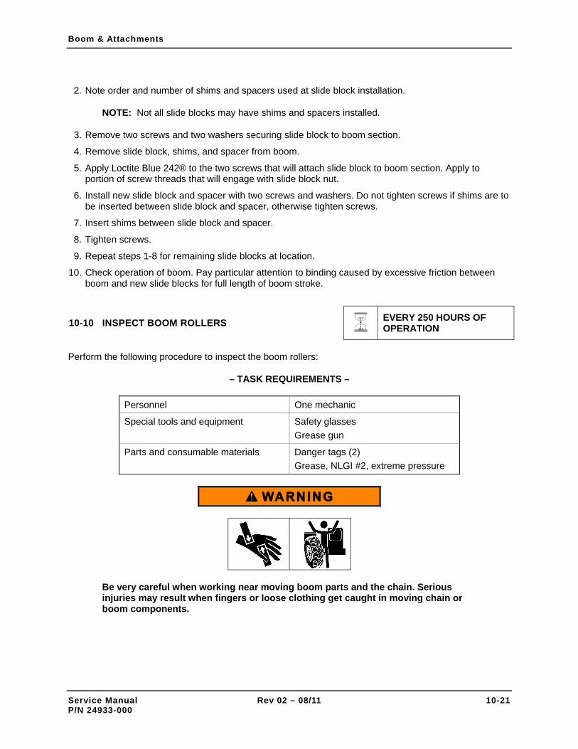
Boom & Attachments
2. Note order and number of shims and spacers used at slide block installation.
NOTE: Not all slide blocks may have shims and spacers installed.
3. Remove two screws and two washers securing slide block to boom section.
4. Remove slide block, shims, and spacer from boom.
5. Apply Loctite Blue 242® to the two screws that will attach slide block to boom section. Apply to portion of screw threads that will engage with slide block nut.
6. Install new slide block and spacer with two screws and washers. Do not tighten screws if shims are to be inserted between slide block and spacer, otherwise tighten screws.
7. Insert shims between slide block and spacer.
8. Tighten screws.
9. Repeat steps 1-8 for remaining slide blocks at location.
10. Check operation of boom. Pay particular attention to binding caused by excessive friction between boom and new slide blocks for full length of boom stroke.
10-10 INSPECT BOOM ROLLERS
EVERY 250 HOURS OF OPERATION
Perform the following procedure to inspect the boom rollers:
– TASK REQUIREMENTS –
Personnel One mechanic
Special tools and equipment Safety glasses Grease gun
Parts and consumable materials Danger tags (2) Grease, NLGI #2, extreme pressure
Be very careful when working near moving boom parts and the chain. Serious injuries may result when fingers or loose clothing get caught in moving chain or boom components.
Service Manual Rev 02 – 08/11 10-21 P/N 24933-000

Boom & Attachments
INITIAL SET-UP
1. Park forklift on level surface. 2. Set Travel Select lever to NEUTRAL (N). 3. Set Parking Brake switch to ON. 4. Extend boom and lower carriage to ground so that boom weight is taken off bottom rollers on outer
boom and mid boom. 5. Set Ignition switch to OFF. 6. Attach danger tags to steering wheel and ignition key. Refer to para. 2-5, for lockout-tagout
procedure.
INSPECTION
1. See Figures 10-9 and 10-10. Inspect boom rollers for the following defects:
• Uneven wear.
• Hairline cracks.
• Corrosion.
• Looseness, worn bearings.
• Loose mounting hardware. Tighten as required.
• Lack of lubricant. Lubricate as required. (Refer to para. 10-2 for lubrication instructions.)
2. Replace defective rollers.
3. Thoroughly check operation of boom.
Figure 10-9. Boom Roller Inspection
Service Manual Rev 02 – 08/11 10-22 P/N 24933-000

Boom & Attachments
Figure 10-10. Location of Boom Rollers
Service Manual Rev 02 – 08/11 10-23 P/N 24933-000

Boom & Attachments
10-11 FORK NOMENCLATURE
See Figure 10-11 and refer to Table 10-1 for a description of fork terms.
Figure 10-11. Fork Nomenclature
Table 10-1. Fork Nomenclature
Term Meaning
Fork Structures
Blade The horizontal portion of the fork upon which the load is supported.
Heel The radiused portion of the fork connecting the blade to the shank.
Shank The upright (vertical) portion of the fork.
Service Manual Rev 02 – 08/11 10-24 P/N 24933-000

Boom & Attachments
Table 10-1. Fork Nomenclature – Cont.
Term Meaning
Tip The free end of the blade.
Fork Surfaces
Blade – upper face The uppermost surface of the blade on which the load is carried.
Bottom The lower surfaces of the blade, including the tapers.
Shank – front face The face of the shank which contacts the load and from which the load center distance is measured.
Flanks The side faces of the blade and shank.
Hook retaining face The inclined faces of the top and the bottom hooks.
Hook suspension face The bottom horizontal face of the top hook in contact with the carriage or fork carrier.
Blade bevel The surfaces of the tip of the blade which are tapered to facilitate insertion of the fork.
Tip flanks (toe flanks) The tip of blade sides which are shaped to facilitate insertion of the fork. (The tip shapes may take various forms.)
Shank top The upper surface of the vertical (or shank).
Shaft The tube used for mounting forks onto shaft-type carriages.
Fork Dimensions
Thickness The thickness of the parallel portion of the blade or shank closest to the heel.
Width The width of the blade.
Back height The distance from the bottom of the blade to the top of the shank.
Length The length of the blade measured from the front of the shank to the extreme tip of the blade.
Cross section The product of the width and thickness.
Angle The angle from the upper face of the blade to the front face of the shank.
Service Manual Rev 02 – 08/11 10-25 P/N 24933-000

Boom & Attachments
10-12 MEASURE FORK FLANK WEAR
EVERY 1,000 HOURS OF OPERATION
Perform the following procedure to measure flank wear:
– TASK REQUIREMENTS –
Personnel One mechanic
Special tools and equipment Safety glasses Fork caliper
Parts and consumable materials Danger tags (2)
INITIAL SET-UP
1. Park forklift on level surface.
2. Set Travel Select lever to NEUTRAL (N).
3. Set Parking Brake switch to ON.
4. Retract boom and lower carriage until forks are about 36" above ground.
5. Set Ignition switch to OFF.
6. Attach danger tags to steering wheel and ignition key. Refer to para. 2-5, for lockout-tagout procedure.
NOTE: Fork calipers are calibrated by first measuring the fork shank thickness. On a new fork, the shank and the flank are the same thickness. The fork flank is subject to continuous wear during normal forklift operation. Therefore, comparing the thickness of the flank to the thickness of the shank is an accurate method for gauging flank wear.
NOTE: In accordance with ASME B56.1, forks must be removed from service if flank wear is equal to or greater than 10 percent. A 10 percent reduction in flank thickness reduces load-carrying capacity by 20 percent.
MEASURING FLANK WEAR
1. To calibrate calipers, measure shank (View A) thickness. Set top jaws of caliper by measuring the thickness of the shank. Ensure that the caliper is held square across the shank for an accurate reading. The caliper is now set to measure the fork blade.
2. To check flank thickness, position the bottom jaws of the caliper over the flanks of the fork.
3. If inside jaws of caliper hit fork (View B), the fork has less than 10% wear and can remain in service.
4. If inside jaws of caliper pass over the fork arm (View C), fork must be taken out of service.
Service Manual Rev 02 – 08/11 10-26 P/N 24933-000

Boom & Attachments
Figure 10-12. Measuring Fork Flank Wear
Service Manual Rev 02 – 08/11 10-27 P/N 24933-000

Boom & Attachments
10-13 FORK INSPECTION
EVERY 1,000 HOURS OF OPERATION
The following information (in italics) is reprinted from ASME/ANSI B56.1-2000, Inspection and Repair of Forks in Service on Fork Lift Trucks.
6.2.8 INSPECTION AND REPAIR OF FORKS IN SERVICE ON FORK LIFT TRUCKS
(a) Forks in use shall be inspected at intervals of not more than 12 months (for single shift operations) or whenever any defect or permanent deformation is detected. Several applications will require more frequent inspection.
(b) Individual and Load Rating of Forks. When forks are used in pairs (the normal arrangement), the rated capacity of each fork shall be at least half of the manufacturer’s rated capacity of the truck, and at the rated load center distance shown on the lift truck nameplate.
6.2.8.1 INSPECTION
Fork inspections shall be carried out carefully by trained personnel with the aim of detecting any damage, failure, deformation, etc., which might impair safe use. Any fork which shows such a defect shall be withdrawn from service, and shall not be returned to service unless it has been satisfactorily repaired in accordance with Para. 6.2.8.2.
(a) Surface Cracks. The fork shall be thoroughly examined visually for cracks and if considered necessary, subjected to a non-destructive crack detection process, special attention being paid to the heel and welds attaching all mounting components to the fork blank. This inspection for cracks must also include any special mounting mechanisms of the fork blank to the fork carrier including bolt type mountings and forged upper mounting arrangements for hook or shaft type carriages. The forks shall not be returned to service if surface cracks are detected.
(b) Straightness of Blade and Shank. The straightness of the upper face of the blade and the front face of the shank shall be checked. If the deviation from straightness exceeds 0.5% of the length of the blade and/or the height of the shank, respectively, the fork shall not be returned to service until it has been repaired in accordance with Para. 6.2.8.2.
(c) Fork Angle (Upper Face of Blade to Load of the Shank). Any fork that has a deviation of greater than 3 deg. from the original specification shall not be returned to service. The rejected fork shall be reset and tested in accordance with Para. 6.2.8.2.
(d) Difference in Height of Fork Tips. The difference in height of one set of forks when mounted on the fork carrier shall be checked. If the difference in tip heights exceeds 3% of the length of the blade, the set of forks shall not be returned to service until repaired in accordance with Para. 6.2.8.2
(e) Positioning Lock (Where Originally Provided). It shall be confirmed that the positioning lock is in good repair and correct working order. If any fault is found, the fork shall be withdrawn from service until satisfactory repair has been effected.
(f) Wear
Service Manual Rev 02 – 08/11 10-28 P/N 24933-000

Boom & Attachments
(1) Fork Blade and Shank. The fork blade and shank shall be thoroughly checked for wear, special attention being paid to the vicinity of the heel. If the thickness is reduced to 90% of the original thickness, the fork shall not be returned to service.
(2) Fork Hooks (Where Originally Provided). The support face of the top hook and the retaining faces of both hooks shall be checked for wear, crushing, and other local deformations. If these are apparent to such an extent that the clearance between the fork and the fork carrier becomes excessive, the fork shall not be returned to service until repaired in accordance with Para. 6.2.8.2.
(g) Legibility of Marking (When Originally Provided). If the fork marking in accordance with Para. 7.25.2 is not clearly legible, it shall be renewed. Marking shall be renewed per instructions from original supplier.
6.2.8.2 REPAIR AND TESTING
(a) Repair. Only the manufacturer of the fork or an expert of equal competence shall decide if a fork may be repaired for continual use, and the repairs shall only be carried out by such parties. It is not recommended that surface cracks or wear be repaired by welding. When repairs necessitating resetting are required, the fork shall subsequently be subjected to an appropriate heat treatment, as necessary.
10-14 MANUALLY RETRACT AND LOWER BOOM
A hydraulic system or engine malfunction may make retracting and lowering the boom impossible. In this situation, the boom can be retracted and lowered by opening manual lowering valves located on the extend cylinder valve block and the left and right boom lift cylinder valve blocks (Figure 10-13). Note that the boom must be above horizontal to accomplish retraction and lowering. Gravity supplies the power required to retract and lower the boom.
Perform the following procedure to manually retract and lower the boom:
– TASK REQUIREMENTS –
Personnel One mechanic
Special tools and equipment Safety glasses
Parts and consumable materials Danger tags (2)
DO NOT get under a raised boom unless the boom is blocked up.
Service Manual Rev 02 – 08/11 10-29 P/N 24933-000

Boom & Attachments
RETRACT BOOM
1. Remove four screws and washers from boom access panel (Figure 10-13, Sheet 1).
2. Remove boom access panel.
3. Loosen locknut on extend cylinder manual lowering valve (Figure 10-13, Sheet 2).
4. Turn extend cylinder manual lowering valve adjustment screw counter-clockwise (CCW) until boom starts to retract. Continue turning adjustment screw until a safe retraction speed is achieved.
Failure to turn the manual lowering valve adjustment screw clockwise and tightening the locknut may cause the boom to bleed out.
5. After boom has retracted, turn extend cylinder manual lowering valve adjustment screw fully clockwise (CW) and tighten locknut.
6. Attach boom access panel to boom with four screws and washers.
LOWER BOOM
A possible left or right cylinder failure may cause the boom to lower unexpectedly when the manual lowering valve adjustment screw is turned fully counter-clockwise.
1. Turn manual lowering valve adjustment screw on left boom lift cylinder fully counterclockwise (approximately five turns).
2. Turn the manual lowering valve adjustment screw on right boom lift cylinder counterclockwise until boom starts to lower. The speed at which boom lowers can be controlled by turning adjustment screw clockwise or counterclockwise.
3. After boom has been lowered, close left and right manual lowering valves by turning adjustment screws in fully clockwise. (With valves closed, boom will operate normally when original hydraulic system or engine malfunction has been repaired.)
Service Manual Rev 02 – 08/11 10-30 P/N 24933-000

Boom & Attachments
Figure 10-13. Boom Lift and Extend Cylinder Manual Lowering Valves (Sheet 1 of 2)
Service Manual Rev 02 – 08/11 10-31 P/N 24933-000

Boom & Attachments
Figure 10-13. Boom Lift and Extend Cylinder Manual Lowering Valves (Sheet 2 of 2)
Service Manual Rev 02 – 08/11 10-32 P/N 24933-000

Checkout Procedures
Section 11
Check-Out Procedures
11-1 CHECK OPERATION OF REAR AXLE STABILIZATION SYSTEM
Perform the following procedure to check the operation of the Rear Axle Stabilization System (RAS):
– TASK REQUIREMENTS –
Personnel One operator and one observer
Special tools and equipment 8" X 8" wood block Head protection
Parts and consumable materials None
The test area must be cleared of personnel and objects which may pose a hazard in case the forklift rolls over during the test.
If the forklift starts to roll over, DO NOT attempt to get out of the cab. Stay in the seat. The cab is designed to provide protection to the operator in the event that the forklift rolls over. Leaving the cab may result in serious injury or death.
PRELIMINARY SET-UP
1. Post an observer to observe procedure and to render immediate aid if necessary.
2. Remove any attachments from carriage adapter.
3. Verify Boom Angle indicator (Figure 11-1) swings freely without drag.
4. Place 8" X 8" wood block in front of left front wheel.
5. Enter cab and adjust seat.
6. Fasten and adjust seat belt.
7. Start engine. Note that all tests are conducted at idle speed (approximately 1,000 rpm).
Service Manual Rev 02 – 08/11 11-1 P/N 24933-000

Checkout Procedures
8. Park forklift on level surface.
9. Retract boom.
10. Raise boom and then lower until boom is horizontal (level) to ground. Verify Boom Angle indicator reads 0 degrees.
11. Retract outriggers (if equipped).
12. Use Frame Sway control to level frame.
13. Verify Rear Axle Locked indicator is OFF.
14. Use Frame Sway control to sway frame full left. Verify Frame Level (slope) indicator (Figure 11-2) displays 11 degrees left.
15. Use Frame Sway control to sway frame full right. Verify Frame Level (slope) indicator displays 11 degrees right.
16. Use Frame Sway control to level forklift. Verify Frame Level (slope) indicator displays 0 degrees.
17. Drive forklift up on 8" X 8" wood block located in front of left front wheel and depress service brake pedal.
18. Set Travel Select lever to NEUTRAL (N).
19. Raise boom to 40 degrees. The Rear Axle Locked light must come ON and remain on.
NOTE: In the following step, observe and record the actual boom angle at which the Rear Axle Locked light comes on.
20. With Service Brake pedal depressed and Parking Brake switch set to OFF, set Travel Select lever to NEUTRAL (N) and raise the boom to 40 degrees.
Figure 11-1. Boom Angle Indicator
Service Manual Rev 02 – 08/11 11-2 P/N 24933-000

Checkout Procedures
Figure 11-2. Frame Level Indicator
NOTE: The following tests should be conducted at one time and in sequence.
TEST NO. 1
The test verifies that the Service Brake activates the RAS (Locked Mode).
TEST SETUP
1. Set Parking Brake switch to OFF.
2. Depress Service Brake pedal just enough to keep Rear Axle Locked indicator ON.
3. Set Travel Select lever to Reverse (R) and 1st gear.
4. Slowly depress Throttle to drive through service brakes sufficient distance to back off block where front left wheel is off ground.
RESULTS
The rear axle remains locked with no oscillation and the left front tire remains airborne.
TEST NO. 2
This test verifies that setting the travel select lever to N activates RAS (Locked Mode).
1. Keep Service Brake depressed and Parking Brake switch set to OFF.
2. Set Travel Selector to NEUTRAL (N).
3. Release Service Brake.
Service Manual Rev 02 – 08/11 11-3 P/N 24933-000

Checkout Procedures
RESULTS
The rear axle must remain locked with no oscillation and the left front tire must remain airborne.
TEST NO. 3
This test verifies that the parking brake activates RAS (Locked Mode).
TEST SETUP
1. Keep Travel Select lever set to NEUTRAL (N).
2. Set Parking Brake switch to ON.
3. Move Travel Select lever to F and select 4th gear.
4. Fully release Service Brake pedal.
RESULTS
The rear axle remains locked with no oscillation and the left front tire remains airborne.
TEST NO. 4
This test verifies frame sway maintains a four-point stance while operating in Slaved Mode.
TEST SETUP
1. Move Travel Select lever to NEUTRAL (N).
2. Set Parking Brake switch to ON.
3. Verify frame sway will not function unless Interlock button is depressed, then activate button and frame sway left about 5 degrees pause then right about 5 degrees beyond the start point.
4. During test verify, frame must sway in Reduced Speed Mode both directions, the Rear Axle Locked light remains ON and the front tire remains off the ground.
RESULTS
Although the tire's height off the ground may change slightly due to the changes in lateral weight distribution, the front to rear axle oscillation relationship is retained.
TEST NO. 5
This test verifies that release of the service brake deactivates the RAS system.
SETUP
1. Depress Service Brake pedal until Rear Axle Locked light comes ON.
Service Manual Rev 02 – 08/11 11-4 P/N 24933-000

Checkout Procedures
2. Set Parking Brake switch to OFF.
3. Set Travel Select lever to REVERSE (R).
4. Select 4th gear.
5. Release Service Brake pedal slowly to deactivate RAS system.
RESULTS
1. The Rear Axle Locked light should go OFF.
2. The left front tire must return to the ground.
3. The forklift may travel in reverse during this test. Allow the forklift to equalize weight on all four tires without depressing service brake.
NOTE: The operator can toggle the RAS between Locked Mode and Restricted Float Mode simply by depressing or releasing the Service Brake pedal. The Rear Axle Locked light must come on and go out consistent with the mode change.
TEST NO. 6
This test verifies frame sway and RAS operation in Restricted Float Mode (Travel Mode).
TEST SETUP
1. Position forklift on level surface.
2. Use the Frame Sway control to level the frame.
3. Depress Service Brake pedal.
4. Raise boom above 45 degrees.
5. The Rear Axle Locked indicator light comes ON.
6. Move range selector to 4th and Travel Select lever to FORWARD (F) or REVERSE (R).
7. Release Service Brake pedal to deactivate Rear Axle Locked Mode. The Rear Axle Locked light must come on and go out consistent with mode change.
8. Press Frame Sway override button and sway frame no more than 7 degrees left while holding Sway Control lever full stroke. (Operator controls frame sway travel and is responsible for maintaining corresponding forklift stability.).
9. Repeat frame sway towards right under same conditions and verify comparable performance.
RESULTS
The frame should sway in the Fast Mode and the front wheel may rise slightly but should return to the ground when frame swaying is stopped.
Service Manual Rev 02 – 08/11 11-5 P/N 24933-000

Checkout Procedures
Service Manual Rev 02 – 08/11 11-6 P/N 24933-000
THIS PAGE INTENTIONALLY LEFT BLANK

Storage & Transportation
Section 12
Storage & Transportation
12-1 GENERAL MAINTENANCE SAFETY
Use caution when performing maintenance on the forklift. Wear personal protective equipment when appropriate and use danger tags. Carefully follow the maintenance procedures provided in this chapter. Read the Material Safety Data Sheets (MSDS) for solvents, cleaners, etc. Read and fully understand the safety information provided in Chapter 2 – Maintenance & Operation Safety, before performing maintenance on the forklift.
12-2 PREPARING ENGINE FOR LONG-TERM STORAGE
Perform the following procedure to prepare the engine for long-term storage (30 days or longer):
– TASK REQUIREMENTS –
Personnel One mechanic
Special tools and equipment Safety glasses
Parts and consumable materials Danger tags (2) Ethylene glycol coolant Oil, 15W-40 API CG4 Oil filters Diesel Fuel Preservative POWERPART Lay-Up 1 Perkins P/N 1772204 Protectant, POWERPART Lay-Up 2, Perkins P/N 1762811 Protectant, POWERPART Lay-Up 3, Perkins P/N 1734115 Waterproof tape Absorbent cotton
Service Manual Rev 02 – 08/11 12-1 P/N 24933-000

Storage & Transportation
NOTE: Several chemicals, lubricants, etc., are required to prepare the engine for storage. Carefully read the instructions printed on the containers prior to using the product.
NOTE: Record all steps done to prepare forklift for long-term storage.
INITIAL SET-UP
1. Park forklift on level surface.
2. Set Travel Select lever to NEUTRAL (N).
3. Set Parking Brake switch to ON.
4. Retract boom and lower carriage. Allow sufficient space to open forklift covers.
5. Set Ignition switch to OFF.
6. Attach danger tags to steering wheel and ignition key. Refer to para. 2-5, for lockout-tagout procedure.
7. Completely clean outside of engine.
FUEL SYSTEM
Fuel that has been stored in the tank and in the fuel system should not be used at the end of the storage period. The fuel should be drained, properly disposed of, and replaced with fresh fuel. The fuel filter must also be replaced. However, the fuel and filter can be prepared for storage and later used safely at the end of the storage period if a preservative is added to it.
1. If preservative fuel is used, drain fuel system and then fill with preservative fuel.
2. If normal fuel is to be retained, add POWERPART Lay-Up 1, Fuel Preservative to fuel tank.
3. Circulate fuel through fuel system by operating engine until it reaches normal operating temperature.
LUBRICATION SYSTEM
If the engine will not be started for several weeks, the lubricating oil will drain from the cylinder walls and from the piston rings. Rust can form on the cylinder walls and cause increased engine wear and reduce service life.
1. Stop engine and drain oil from oil pan. Dispose of oil properly.
2. Replace oil filters. Dispose of oil filters properly.
3. Fill oil pan to full mark on dipstick with new, clean lubricating oil.
4. Add POWERPART Lay-Up 2 to oil in order to protect engine against corrosion.
Service Manual Rev 02 – 08/11 12-2 P/N 24933-000

Storage & Transportation
5. If POWERPART Lay-Up 2 is not available, use a preservative of the correct specification instead of lubricating oil. If a preservative is used, this must be drained completely at end of the storage period and oil pan must be refilled to correct level with normal lubricating oil.
6. Operate engine for short period of time to circulate oil. Check for leaks.
COOLING SYSTEM
Do not drain coolant while engine is still hot and the system is under pressure because dangerous hot coolant can be discharged.
1. Remove filler cap of cooling system.
2. Remove drain plug from the side of cylinder block in order to drain engine. Ensure that drain hole is not restricted.
3. Place container beneath radiator drain plug.
4. Open radiator drain plug to drain radiator.
5. Flush cooling system with clean water.
6. Re-install drain plugs and filler cap.
7. Close radiator drain plug.
8. Fill cooling system with 50% ethylene glycol / 50% water mixture. Note that this mixture provides protection against corrosion.
9. Operate engine for short period in order to circulate coolant in engine.
BATTERY
1. Check battery condition indicator. Battery should be fully charged before being placed in storage.
2. Disconnect cables from battery.
3. Clean battery terminals and coat with POWERPART Lay-Up 3.
4. Put battery into safe storage.
FUEL INJECTION SYSTEM
1. Clean engine breather pipe and seal end of pipe with waterproof tape.
2. Remove fuel injector nozzles and spray POWERPART Lay-Up 2 for one or two seconds into each cylinder bore with piston at bottom dead center.
3. Slowly turn crankshaft for one complete revolution and then re-install fuel injector nozzles.
AIR INDUCTION SYSTEM
1. Remove air filter assembly.
2. If necessary, remove pipes that are installed between air filter assembly and turbocharger.
Service Manual Rev 02 – 08/11 12-3 P/N 24933-000

Storage & Transportation
3. Spray POWERPART Lay-Up 2 Protectant into turbocharger. The duration of the spray time should be 50% longer than the time indicated on the container label.
4. Seal turbocharger with waterproof tape.
EXHAUST SYSTEM
1. Remove exhaust pipe.
2. Spray POWERPART Lay-Up 2 Protectant into turbocharger. Duration of spray time should be 50% longer than time indicated on container label.
3. Seal the turbocharger with waterproof tape.
GENERAL ENGINE
1. Remove valve cover filler cap.
2. Spray POWERPART Lay-Up 2 Protectant around rocker shaft assembly.
3. Re-install filler cap.
4. Seal fuel filler cap with waterproof tape.
5. Remove drive belts and put into storage.
6. In order to prevent corrosion, spray engine with POWERPART Lay-Up 3 Protectant. Be careful not to spray area inside alternator cooling fan.
7. Seal off engine openings with absorbent cotton to keep moisture out.
12-3 PREPARING FORKLIFT FOR LONG-TERM STORAGE
Perform the following procedure to prepare a forklift for long-term storage:
– TASK REQUIREMENTS –
Personnel One mechanic
Special tools and equipment Grease gun Tarp
Parts and consumable materials Danger tags (2) Grease, extreme pressure NLGI #2 Transmission fluid, Dexron III Oil, SAE 80W-90 EP API GL5 Rust inhibiting lubricant Protectant, vinyl & rubber Waterproof tape
1. Lubricate all grease fittings.
2. Top off transmission fluid.
Service Manual Rev 02 – 08/11 12-4 P/N 24933-000

Storage & Transportation
3. Top off front and rear axle oil.
4. Wash and wax the exterior finish.
5. Apply rust-inhibiting lubricant to all exposed cylinder rods.
6. Apply protectant to tires.
7. Apply protectant to operator seat.
8. Seal tail pipe with waterproof tape to prevent entry in exhaust system by rodents, etc.
9. If the forklift will be in storage for a year or more, support it on jack stands or blocks. This will take the weight off of the wheel bearings.
10. Remove wheels and tires and store them flat and out of the sunlight.
11. If possible, store forklift indoors where it will be protected from adverse weather.
12. If forklift is to be stored outside, park it on concrete or asphalt, or wood planks laid out over dirt. Cover forklift with a tarp.
12-4 TRANSPORTING FORKLIFT
Refer to Table 12-1 for forklift operating weights and see Figure 12-1 for the location of forklift tie-down points.
Xtreme Manufacturing is not responsible for any aspect of forklift transportation. The owner/operator assumes full responsibility for:
• Choosing the proper method of transportation.
• Choosing the proper tie-down devices.
• Ensuring the equipment used is capable of supporting the weight of the forklift being transported.
• Ensuring that Department of Transportation and other federal or state laws and regulations are followed.
• Ensuring that all safety rules of their employer are followed.
• Ensuring that all manufacturer's instructions and warnings are followed.
Table 12-1. Forklift Operating Weights
Forklift Model Operating Weight (Lbs.)
XR620/621 12,700
XR842 26,850
XR1045 27,130
XR1245 32,930
Service Manual Rev 02 – 08/11 12-5 P/N 24933-000

Storage & Transportation
Table 12-1. Forklift Operating Weights – Cont.
Forklift Model Operating Weight (Lbs.)
XR1255 35,700
XR1267 46,300
XR1270 47,300
XR1534 29,000
XR1642 41,000
XR2034 40,140
XR2045 44,750
XR2450 48,750
XR3034 47,850
NOTE: MODEL XR1245/1255/1267/1270/2045/2450 FORKLIFTS HAVE TWO TIE-DOWN POINTS AT FRONT OF OUTRIGGER MOUNT.
Figure 12-1. Tie-Down Point Locations
Service Manual Rev 02 – 08/11 12-6 P/N 24933-000

Index
Index
Description Page No.
Adjusting Engine Valve Clearances, Checking 5-29
Air Breather 8-15
Air Breather, Replacing 8-14
Air Filter Assembly, Engine 5-10
Air Filter Dust Cup, Emptying 5-9
Air Filter, Checking 5-25
Air Filter, Replacing 5-24
Applicability of Manual 1-1
Auxiliary Battery Installation 9-12
Auxiliary Battery, Connecting 9-13
Auxiliary Battery, Installing 9-10
Axle Cylinder and Outrigger Lubrication 4-1
Axle Cylinders and Outriggers, Lubrication 4-3
Axle Data Plates, Location 1-13
Battery and Cables 9-4
Battery and Cables, Checking Condition 9-3
Battery Cable Description 9-3
Battery Description 9-3
Battery Disconnect Switch 2-7
Battery Handling and Maintenance 2-8
Battery Installation 9-7
Battery Safety 9-1
Battery, Inspecting and Cleaning 9-8
Battery, Replacing 9-4
Boom & Attachments 10-1
Service Manual Rev 02 – 08/11 Index-1 P/N 24933-000

Index
Service Manual Rev 02 – 08/11 Index-2 P/N 24933-000
Description Page No.
Boom and Attachment Lubrication 10-2
Boom and Attachment Lubrication 10-4
Boom Angle Indicator 11-2
Boom Chain Tension Adjustment 10-18
Boom Chain Tension, Checking and Adjusting 10-17
Boom Chains, Inspecting 10-9
Boom Extend Chain Lubrication 10-9
Boom Extend Chain, Lubrication 10-8
Boom Isolation Manifold Valve Torque Values 8-36
Boom Lift and Extend Cylinder Manual Lowering Valves 10-34
Boom Roller Inspection 10-24
Boom Rollers, Inspecting 10-23
Boom Rollers, Location 10-25
Boom Slide Blocks 10-20
California Proposition 65 Warnings 2-11
Canister-Type Oil Filter 5-16
Cap Screw Torque Values 1-23
Carrying a Load 2-16
Cartridge Valve Solenoid 8-30
Cartridge Valve Solenoid, Replacing 8-29
Cartridge Valve, Replacing 8-27
Chain Damage Inspection 10-12
Chain Edge Wear Measurement 10-14
Chain Edge Wear, Measuring 10-13
Chain Elongation Measurement 10-16
Chain Elongation, Measuring 10-15
Chain Nomenclature 10-10
Chain, Visually Inspecting 10-10
Chassis and Engine Data Plates, Location 1-11

Index
Service Manual Rev 02 – 08/11 Index-3 P/N 24933-000
Description Page No.
Check Condition and Tension of Drive Belts 5-11
Check Engine Coolant Level 5-3
Check for Water in Fuel-Water Separator 5-7
Check-Out Procedures 11-1
Component Data Plates 1-10
Condition Tags A-17
Coolant Level Indicator 5-5
Coolant Recovery Tank and Radiator Drain 5-20
Cooling System, Drain and Flush 5-22
Cylinder and Valve Numbers 5-29
Cylinder Block Drain Plug 5-23
Danger and Condition Tags 2-6
Danger Tags A-17
Distribution Manifold Torque Values (XR1245/1255) 8-37
Distribution Manifold Torque Values (XR842/1045) 8-36
Drive Belt Condition and Tension, Checking 5-26
Drive Belt Tension, Checking 5-27
Electrical Center Assembly 9-13
Electrical Center Fuses and Circuit Breaker 9-17
Electrical Center Relays 9-17
Electrical Center Relays and Fuses 9-14
Electrical System 9-1
Engine 5-1
Engine Hoses and Connections, Checking 5-30
Engine Oil Level, Checking 5-1
Engine Oil, Changing 5-11
Engine Operation and Maintenance 2-10
Engine Specifications 1-22
Engine Wiring and Connections, Checking 5-32

Index
Service Manual Rev 02 – 08/11 Index-4 P/N 24933-000
Description Page No.
Filter and Strainer Part Numbers 1-15
Filter, High-Pressure 8-18
Filters and Strainers 1-15
Fork Flank Wear, Measuring 10-29
Fork Inspection 10-31
Fork Inspection Log A-11
Fork Nomenclature 10-27
Forklift and Engine Specifications 1-16
Forklift Cab 1-8
Forklift Covers 1-7
Forklift Hourmeter 3-1
Forklift Nomenclature 1-2, 1-3
Forklift Operating Weights 7-5, 12-5
Frame Level Indicator 11-3
Front Control Panel 1-9
Fuel Filter Element 5-18
Fuel Filter, Replacing 5-17
Fuel Handling and Maintenance 2-10
Fuel-Water Separator 5-8
Functional Test Checklist 2-13
Functional Tests 2-11
Fuse Block Fuses 9-18
Fuse Condition 9-22
Fuse, Replacing 9-21
General 2-1
General Information & Specifications 1-1
General Maintenance Precautions 2-7
General Maintenance Safety 4-1, 5-1
Grease Fittings List A-15
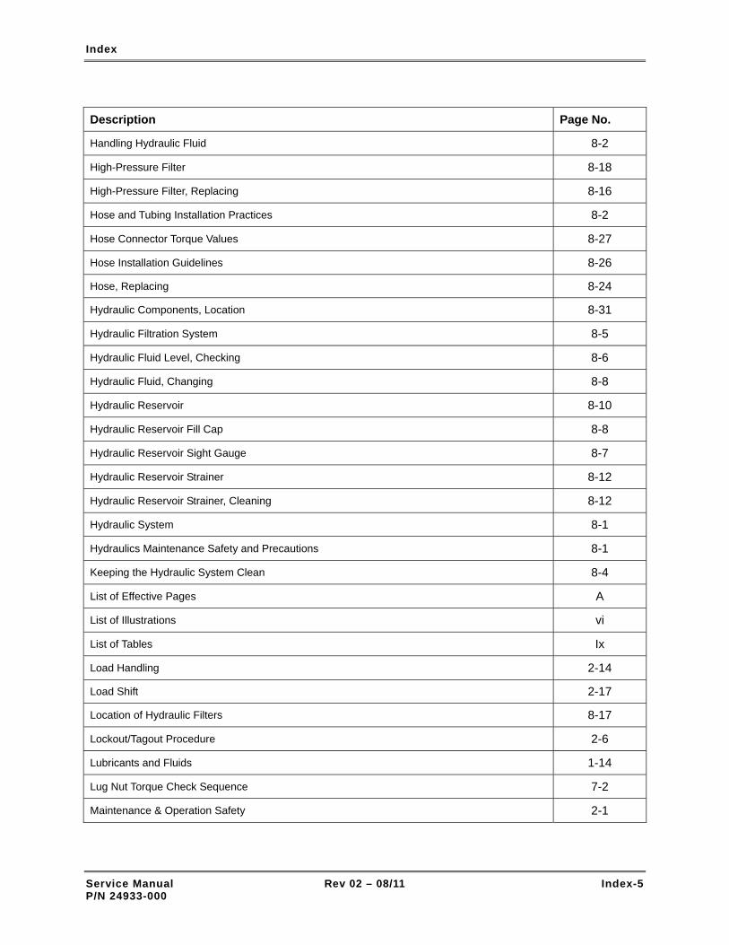
Index
Service Manual Rev 02 – 08/11 Index-5 P/N 24933-000
Description Page No.
Handling Hydraulic Fluid 8-2
High-Pressure Filter 8-18
High-Pressure Filter, Replacing 8-16
Hose and Tubing Installation Practices 8-2
Hose Connector Torque Values 8-27
Hose Installation Guidelines 8-26
Hose, Replacing 8-24
Hydraulic Components, Location 8-31
Hydraulic Filtration System 8-5
Hydraulic Fluid Level, Checking 8-6
Hydraulic Fluid, Changing 8-8
Hydraulic Reservoir 8-10
Hydraulic Reservoir Fill Cap 8-8
Hydraulic Reservoir Sight Gauge 8-7
Hydraulic Reservoir Strainer 8-12
Hydraulic Reservoir Strainer, Cleaning 8-12
Hydraulic System 8-1
Hydraulics Maintenance Safety and Precautions 8-1
Keeping the Hydraulic System Clean 8-4
List of Effective Pages A
List of Illustrations vi
List of Tables Ix
Load Handling 2-14
Load Shift 2-17
Location of Hydraulic Filters 8-17
Lockout/Tagout Procedure 2-6
Lubricants and Fluids 1-14
Lug Nut Torque Check Sequence 7-2
Maintenance & Operation Safety 2-1

Index
Service Manual Rev 02 – 08/11 Index-6 P/N 24933-000
Description Page No.
Maintenance Forms & Safety Tags A-1
Maintenance History Log A-8
Maintenance Practices 8-3
Maintenance Requirements for Failed Pump 8-38
Maintenance Requirements, Long-Interval 3-5
Maintenance Schedule A-2, 3-1
Making Leak-Free Connections 8-2, 8-3
Manually Retracting and Lowering Boom 10-33
Model XR1045 Specifications 1-17
Model XR1245 Specifications 1-18
Model XR1255 Specifications 1-19
Model XR1267 Specifications 1-20
Model XR1270 Specifications 1-21
Model XR1534 Specifications 1-22
Model XR1642 Specifications 1-23
Model XR2034 Specifications 1-24
Model XR2045 Specifications 1-25
Model XR2450 Specifications 1-26
Model XR3034 Specifications 1-27
Model XR620/621 Specifications 1-15
Model XR842 Specifications 1-16
Notes A-18, 2-1
Oil and Coolant Leaks, Checking 5-6
Oil Drain Plug and Dipstick 5-13
Oil Fill Cap and Dipstick, Engine 5-3
Oil Filter, Element-Type 5-15
Oil Filters, Replacing 5-14
Oil, Coolant, and Fuel Leaks, Checking 5-33
Operating Conditions 8-2

Index
Service Manual Rev 02 – 08/11 Index-7 P/N 24933-000
Description Page No.
Operator Hand Signals 2-17
Outrigger Grease Fittings – XR1245/1255/1267/1270/2045/2450 4-4
Picking Up a Load 2-16
Placing a Load 2-16
Pre-Operation Checklist A-1, A-13
Preparing Engine for Long-Term Storage 12-1
Preparing Forklift for Long-Term Storage 12-4
Preventive Maintenance – After Every 1,000 Hours of Operation 3-4
Preventive Maintenance – After Every 2,000 Hours of Operation 3-5
Preventive Maintenance – After Every 250 Hours of Operation 3-3
Preventive Maintenance – After Every 50 Hours of Operation 3-2
Preventive Maintenance – After Every 500 Hours of Operation 3-3
Preventive Maintenance – After Every 8 Hours of Operation 3-1
Preventive Maintenance – After First 50 Hours of Operation 3-2
Preventive Maintenance and History Logs A-1
Preventive Maintenance Program, Establishing 3-1
Prohibited Practices 2-17
Proper Use of Forks 2-17
Radiator 5-5
Radiator Hoses and Connections 5-32
Radiator Hoses and Connections, Checking 5-31
Rear Axle Cylinder Grease Fittings 4-3
Rear Axle Cylinder Valve Torque Values 8-36
Rear Axle Stabilization System, Checking Operation 12-1
Recommended Engine Oil Viscosity Grades 5-13
Related Technical Documentation 1-1
Relay Assembly Relays and Fuse, Engine 9-18
Relay Assembly, Engine 9-18, 9-19
Relay, Replacing 9-20

Index
Service Manual Rev 02 – 08/11 Index-8 P/N 24933-000
Description Page No.
Relays B through G, P/N 12068567, Correct Installation 9-20
Return Line Filter, Replacing 8-19
Return Line Filter 8-20
SAE Grade 8 Bolt Markings 1-25
Safe Operation Checklist 2-12
Safety Labels 2-24
Safety Signal Words 2-1
Safety Symbols 2-2
Safety Tags A-1
Scope of Manual 1-1
Service Bulletins B, 1-1
Service Bulletins B
Side Control Console 1-10
Slide Block Inspection 10-18
Slide Blocks 10-18
Slide Blocks, Replacing 10-22
Specific Gravity Chart 5-21
Specific Gravity of Coolant, Checking 5-19
Storage & Transportation 12-1
Suction Strainer, Replacing 8-10
Table of Contents I
Taking Hydraulic Fluid Sample 8-21
Tie-Down Point Locations 12-6
Tightening Loose Fittings 8-27
Tightening Torque Values – Cap Screws 1-24
Tire, Replacing 7-7
Torque Wrench Use 1-23
Transmission Data Plates, Location 1-12
Transporting Forklift 12-5

Index
Service Manual Rev 02 – 08/11 Index-9 P/N 24933-000
Description Page No.
Using a Grease Gun 4-2
Using Compressed Air Safely 2-8
Valve Tip Clearances, Checking and Adjusting 5-28
Viton Seals 2-7
Wheel Lug Nut Tightening Sequence 7-6
Wheel Lug Nut Torque, Checking 7-1
Wheel/Tire Assembly 7-4
Wheel/Tire Assembly, Inspecting 7-3
Wheel/Tire Assembly, Replacing 7-4
Wheels & Tires 7-1

Maintenance Forms & Safety Tags
Appendix
Maintenance Forms and Safety Tags
A-1 PREVENTIVE MAINTENANCE AND HISTORY LOGS
Scheduled maintenance is essential to forklift operational reliability and safety. The following documents are provided to assist new forklift owners in the implementation of a successful preventive maintenance program:
• Maintenance Schedule.
• Maintenance History Log.
• Fork Inspection Log.
Note that the Preventive Maintenance Log is functionally identical to the maintenance requirements provided in Section 3, Maintenance Schedule.
A-2 PRE-OPERATION CHECKLIST
A Pre-Operation Checklist is provided to help the operator or mechanic verify that all forklift systems and subsystems are operating correctly.
A-3 SAFETY TAGS
Safety tags, consisting of danger and condition tags, are provided at the end of this Appendix. The danger tags should be attached to the ignition key and steering wheel as directed by the maintenance procedures contained within this manual. Refer to para. 2-5 for the lockout-tagout procedure and instructions in the use of the condition tag.
Service Manual Rev 02 – 08/11 A-1 P/N 24933-000

Maintenance Schedule
EVERY DAY OR 8 HOURS OF OPERATION
REQUIREMENT COMMENTS CHECK-OFF
Check engine oil level
Check engine coolant level
Check engine for oil and coolant leaks
Check for water in fuel-water separator
In extremely dusty conditions, empty air filter dust cup. Also, check air filter and replace if necessary.
Check condition of battery and cables
Check condition and tension (by hand) of engine drive belts
Check transmission fluid level
Check hydraulic fluid level
A-2

AFTER FIRST 50 HOURS OF OPERATION
REQUIREMENT COMMENTS CHECK-OFF
Change engine oil and filters
Check air filter. Replace if necessary.
Replace fuel filter
Check engine hoses and connections for leaks, damage, and tightness
Check radiator hoses for leaks, damage, and tightness
Check engine electrical cables, leads, and connections for damage and tightness
Check for oil and coolant leaks
Check condition and tension of drive belts. Use tensiometer to check belt tension.
Lubricate front and rear driveshaft grease fittings
Lubricate front and rear axle grease fittings
Change differential oil
Change wheel-end oil
Check wheel lug nuts torqued to 380-420 ft-lbs
Lubricate boom pivot point grease fittings
Lubricate front and rear axle cylinder pivot point grease fittings
Lubricate left and right outrigger pivot point (1245/1255/1267/1270/2045/2450) grease fittings
Lubricate boom roller grease fittings and chains
Replace hydraulic return line filter
Replace transmission filter and top off fluid
A-3

AFTER EVERY 50 HOURS OF OPERATION
REQUIREMENT 50 100 150 200 250 300 350 400 450 500
Lubricate boom pivot point grease fittings
Lubricate front and rear axle cylinder pivot point grease fittings
Lubricate left and right outrigger pivot point grease fittings (1245/1254/1267/1270/2045/2450)
AFTER EVERY 250 HOURS OF OPERATION
REQUIREMENT 250 500 750 1000 1250 1500 1750 2000
Comply with 50-Hour Maintenance Requirements
Change engine oil and filters
Check air filter. Replace if necessary.
Check tension and condition of drive belts. Use tensiometer to check belt tension.
Lubricate front and rear driveshaft grease fittings
Lubricate front and rear axle grease fittings
Check differential oil level
Check wheel-end oil level
Check boom chain tension. Adjust if necessary.
Inspect boom rollers and slide blocks for condition and tightness
Lubricate boom roller grease fittings and chains
A-4

AFTER EVERY 500 HOURS OF OPERATION
REQUIREMENT 500 1,000 1,500 2,000 2,500 3,000 3,500 4,000
Comply with 50-Hour Maintenance Requirements
Comply with 250-Hour Maintenance Requirements
Replace air filter
Replace fuel filter
Empty air filter dust cup
Check engine hoses and connections for leaks, damage, and tightness
Check radiator hoses for leaks, damage, and tightness
Check engine electrical cables, leads, and connections for damage and tightness
Check specific gravity of engine coolant
Replace transmission filter and top off fluid
Replace hydraulic reservoir air breather
Replace hydraulic return line filter
Inspect wheel/tire assemblies
A-5

AFTER EVERY 1,000 HOURS OF OPERATION
REQUIREMENT 1,000 2,000 3,000 4,000 5,000 6,000 7,000 8,000
Comply with 50-Hour Maintenance Requirements
Comply with 250-Hour Maintenance Requirements
Comply with 500-Hour Maintenance Requirements
Replace transmission fluid and filters
Change wheel-end oil
Change differential oil
Check valve tip clearance. Adjust if necessary.
Inspect boom chains
Replace hydraulic high-pressure filter
A-6

A-7
AFTER EVERY 2,000 HOURS OF OPERATION
REQUIREMENT 2,000 4,000 6,000 8,000 10,000 12,000 14,000 16,000
Comply with 50-Hour Maintenance Requirements
Comply with 250-Hour Maintenance Requirements
Comply with 500-Hour Maintenance Requirements
Comply with 1,000-Hour Maintenance Requirements
Change hydraulic fluid
Clean or replace hydraulic reservoir strainer
LONG-INTERVAL MAINTENANCE REQUIREMENTS
REQUIREMENT 4,000 8,000 12,000 16,000 20,000 24,000 28,000 32,000
Drain and flush cooling system – After every 4,000 hours of operation

Maintenance History Log
FORKLIFT MODEL: _________________________________________
SERIAL NO.: _________________________________________
DATE MALFUNCTION CORRECTIVE ACTION COMMENTS
A-8

Maintenance History Log
FORKLIFT MODEL: _________________________________________
SERIAL NO.: _________________________________________
A-9

A-10
Maintenance History Log
FORKLIFT MODEL: _________________________________________
SERIAL NO.: _________________________________________
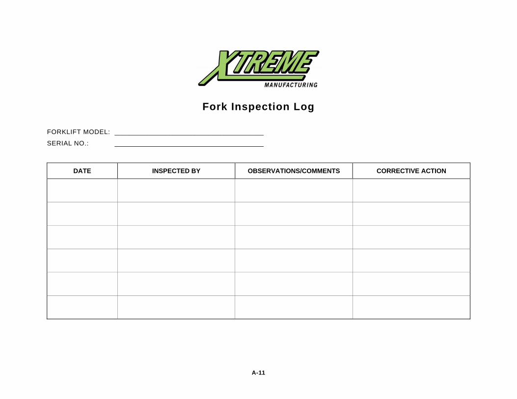
Fork Inspection Log
FORKLIFT MODEL: _________________________________________
SERIAL NO.: _________________________________________
DATE INSPECTED BY OBSERVATIONS/COMMENTS CORRECTIVE ACTION
A-11

A-12
Fork Inspection Log
FORKLIFT MODEL: _________________________________________
SERIAL NO.: _________________________________________
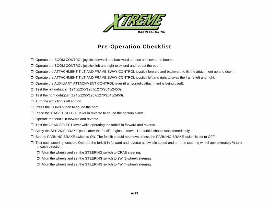
A-13
Pre-Operation Checklist
Operate the BOOM CONTROL joystick forward and backward to raise and lower the boom.
Operate the BOOM CONTROL joystick left and right to extend and retract the boom.
Operate the ATTACHMENT TILT AND FRAME SWAY CONTROL joystick forward and backward to tilt the attachment up and down.
Operate the ATTACHMENT TILT AND FRAME SWAY CONTROL joystick left and right to sway the frame left and right.
Operate the AUXILIARY ATTACHMENT CONTROL lever (if a hydraulic attachment is being used).
Test the left outrigger (1245/1255/1267/1270/2045/2450).
Test the right outrigger (1245/1255/1267/1270/2045/2450).
Turn the work lights off and on.
Press the HORN button to sound the horn.
Place the TRAVEL SELECT lever in reverse to sound the backup alarm.
Operate the forklift in forward and reverse.
Test the GEAR SELECT lever while operating the forklift in forward and reverse.
Apply the SERVICE BRAKE pedal after the forklift begins to move. The forklift should stop immediately.
Set the PARKING BRAKE switch to ON. The forklift should not move unless the PARKING BRAKE switch is set to OFF.
Test each steering function. Operate the forklift in forward and reverse at low idle speed and turn the steering wheel approximately ¼ turn in each direction.
Align the wheels and set the STEERING switch to CRAB steering.
Align the wheels and set the STEERING switch to 2W (2-wheel) steering.
Align the wheels and set the STEERING switch to 4W (4-wheel) steering.

A-14
Pre-Operation Checklist – Cont.
Check the operator control panel gauges after the engine warms to the proper operating range:
Check the VOLTS gauge. The gauge should read between 11 to 15 volts.
Check the COOLANT gauge. The gauge should read between 180 to 200°F.
Check the OIL gauge. The gauge should read between 40 to 80 psi.
Check the FUEL gauge and verify the gauge reads between 2/4 and 4/4. Fill the fuel tank if the gauge shows less than 2/4.
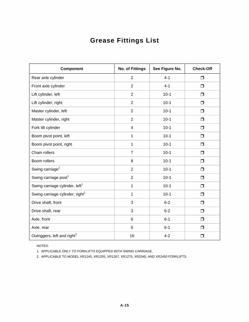
Grease Fittings List
Component No. of Fittings See Figure No. Check-Off
Rear axle cylinder 2 4-1
Front axle cylinder 2 4-1
Lift cylinder, left 2 10-1
Lift cylinder, right 2 10-1
Master cylinder, left 2 10-1
Master cylinder, right 2 10-1
Fork tilt cylinder 4 10-1
Boom pivot point, left 1 10-1
Boom pivot point, right 1 10-1
Chain rollers 7 10-1
Boom rollers 8 10-1
Swing carriage1 2 10-1
Swing carriage post1 2 10-1
Swing carriage cylinder, left1 1 10-1
Swing carriage cylinder, right1 1 10-1
Drive shaft, front 3 6-2
Drive shaft, rear 3 6-2
Axle, front 6 6-1
Axle, rear 6 6-1
Outriggers, left and right2 16 4-2
NOTES: 1. APPLICABLE ONLY TO FORKLIFTS EQUIPPED WITH SWING CARRIAGE. 2. APPLICABLE TO MODEL XR1245, XR1255, XR1267, XR1270, XR2045, AND XR2450 FORKLIFTS.
A-15

A-16

A-17

A-18
Notes

A-19
Notes

A-20
Notes

Contact
Xtreme Manufacturing, LLC 1415 West Bonanza Road
Las Vegas, NV 89106 (702) 851-3750
www.xtrememanufacturing.com
Sales (702) 858-2404
Product Support (702) 636-2969
Engineering (702) 851-3750 (702) 646-2196 (fax)
MODEL NO. ____________________
SERIAL NO. ____________________