service manual - lochinvarlochinvar.com/_linefiles/erp-ser.pdf1 service (continued) service manual 9...
TRANSCRIPT

Service ManualModels: ER152, ER202,
ER252, ER302, and ER402
This manual must only be used by aqualified heating installer / servicetechnician. Read all instructions,including this manual and the EnergyRiteInstallation and Operation Manual,before installing. Perform steps in theorder given. Failure to comply couldresult in severe personal injury, death, orsubstantial property damage.
�� WARNING
Save this manual for future reference.

2
Service Manual
Contents . . . . . . . . . . . . . . . . . . . . . . . . . . . . . . . . . . . . . . . . . . . . . . . . . . . . . . . 2
Hazard definitions . . . . . . . . . . . . . . . . . . . . . . . . . . . . . . . . . . . . . . . . . . . . . . . . 2
Please read before proceeding . . . . . . . . . . . . . . . . . . . . . . . . . . . . . . . . . . . . . 3
What is in this manual? . . . . . . . . . . . . . . . . . . . . . . . . . . . . . . . . . . . . . . . . . . . 5
1. Service . . . . . . . . . . . . . . . . . . . . . . . . . . . . . . . . . . . . . . . . . . . . . . . . . . . . . 6
General Operation . . . . . . . . . . . . . . . . . . . . . . . . . . . . . . . . . . . . . . . . . . 9
Access Setup Menu . . . . . . . . . . . . . . . . . . . . . . . . . . . . . . . . . . . . . . . . . 10
Access Service Menu . . . . . . . . . . . . . . . . . . . . . . . . . . . . . . . . . . . . . . . 11
2. Maintenance . . . . . . . . . . . . . . . . . . . . . . . . . . . . . . . . . . . . . . . . . . . . . . . . . 13
Burner removal and cleaning . . . . . . . . . . . . . . . . . . . . . . . . . . . . . . . . . 15
Heat exchanger cleaning . . . . . . . . . . . . . . . . . . . . . . . . . . . . . . . . . . . . . 17
Combustion air shutter adjustment . . . . . . . . . . . . . . . . . . . . . . . . . . . . 18
Facts about water chemistry . . . . . . . . . . . . . . . . . . . . . . . . . . . . . . . . . 20
Heat exchanger inspection . . . . . . . . . . . . . . . . . . . . . . . . . . . . . . . . . . . 21
Prevention of freezing . . . . . . . . . . . . . . . . . . . . . . . . . . . . . . . . . . . . . . . 21
Winterizing . . . . . . . . . . . . . . . . . . . . . . . . . . . . . . . . . . . . . . . . . . . . . 21
3. Troubleshooting . . . . . . . . . . . . . . . . . . . . . . . . . . . . . . . . . . . . . . . . . . . . . . 22
Troubleshooting Chart - No Display . . . . . . . . . . . . . . . . . . . . . . . . . . . . 22
Checking temperature sensors . . . . . . . . . . . . . . . . . . . . . . . . . . . . . . . . 23
Troubleshooting Chart - Noisy System . . . . . . . . . . . . . . . . . . . . . . . . . . 24
Troubleshooting Chart - Fault Messages . . . . . . . . . . . . . . . . . . . . . . . . 25
Gas Manifold Pressure Adjustment Procedure . . . . . . . . . . . . . . . . . . . . 28
Checking Gas Supply Pressure . . . . . . . . . . . . . . . . . . . . . . . . . . . . . . . . 30
Contents
Hazard definitionsThe following defined terms are used throughout this manual to bring attention to the presence of hazards of various risk levelsor to important information concerning the life of the product.
�� DANGER
�� WARNING
�� CAUTION
CAUTION
NOTICE
DANGER indicates an imminently hazardous situation which, if not avoided, will result in death orserious injury.
WARNING indicates a potentially hazardous situation which, if not avoided, could result in death orserious injury.
CAUTION indicates a potentially hazardous situation which, if not avoided, may result in minor ormoderate injury.
CAUTION used without the safety alert symbol indicates a potentially hazardous situation which, if notavoided, may result in property damage.
NOTICE indicates special instructions on installation, operation, or maintenance that are important butnot related to personal injury or property damage.

Please read before proceeding
Installer – Read all instructions,including this manual and theEnergyRite Installation and OperationManual, before installing. Perform stepsin the order given.
User – This manual is for use only by aqualified heating installer/servicetechnician. Refer to the EnergyRiteUser’s Information Manual for yourreference.
Have this pool heater serviced/inspectedby a qualified service technician at leastannually.
Failure to comply with the above couldresult in severe personal injury, death orsubstantial property damage.
When calling or writing about the poolheater – Please have the pool heater modeland serial number from the pool heaterrating plate.
Consider piping and installation whendetermining pool heater location (see theEnergyRite Installation and OperationManual).
Any claims for damage or shortage inshipment must be filed immediately againstthe transportation company by theconsignee.
Service Manual
3
Handling ceramic fiber materialsREMOVAL OF COMBUSTION CHAMBER LINING
The combustion chamber insulation in this product contains ceramic fiber material. Ceramic fibers can beconverted to cristobalite in very high temperature applications. The International Agency for Research onCancer (IARC) has concluded, “Crystalline silica inhaled in the form of quartz or cristobalite fromoccupational sources is carcinogenic to humans (Group 1).”:
� Avoid breathing dust and contact with skin and eyes.• Use NIOSH certified dust respirator (N95). This type of respirator is based on the OSHA
requirements for cristobalite at the time this document was written. Other types of respirators may be needed depending on the job site conditions. Current NIOSH recommendations can be found on the NIOSH website at http://www.cdc.gov/niosh/homepage.html. NIOSH approved respirators,manufacturers, and phone numbers are also listed on this website.
• Wear long-sleeved, loose fitting clothing, gloves, and eye protection.
� Apply enough water to the combustion chamber lining to prevent airborne dust.
� Remove the combustion chamber lining from the pool heater and place it in a plastic bag for disposal.
� Wash potentially contaminated clothes separately from other clothing. Rinse clothes washerthoroughly.
NIOSH stated First Aid.
� Eye: Irrigate immediately.� Breathing: Fresh air.
�� WARNING NOTICE
�� WARNING
4
Service Manual
Please read before proceeding
When servicing pool heater –
• To avoid electric shock, disconnect electrical supply before performing maintenance.
• To avoid severe burns, allow the pool heater to cool before performing maintenance.
Pool heater operation –
• Do not block flow of combustion or ventilation air to the pool heater.
• Should overheating occur or gas supply fail to shut off,do not turn off or disconnect electrical supply to circulator. Instead, shut off the gas supply at a location external to the appliance.
• Do not use this pool heater if any part has been under water. The possible damage to a flooded appliance can be extensive and present numerous safety hazards. Any appliance that has been under water must be replaced.
Pool heater water –
• Do not use petroleum-based cleaning or sealing compounds in the pool heater system. Gaskets and seals in the system may be damaged. This can result in substantial property damage.
• Do not use “homemade cures” or “pool heater patent medicines”. Serious damage to the pool heater,personnel, and/or property may result.
Service Manual
5
What is in this manual?Service
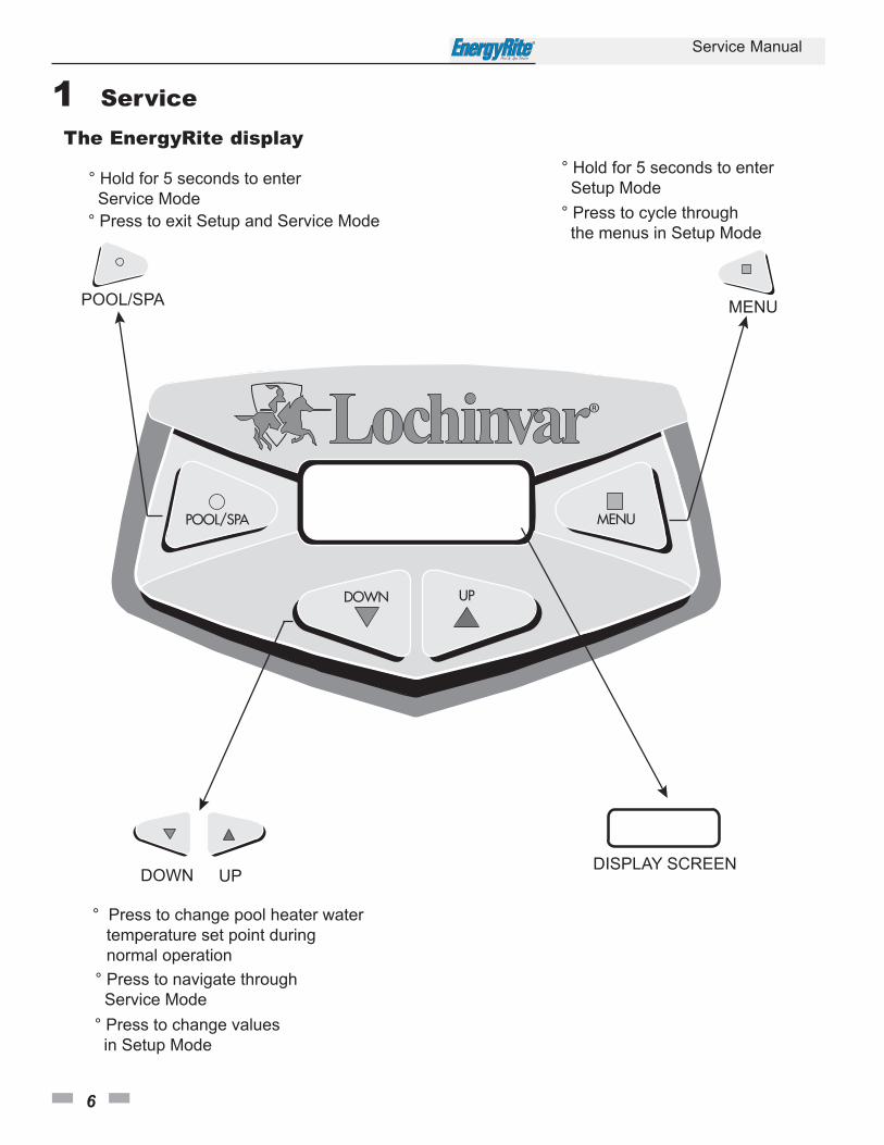
The EnergyRite display
• Display panel readout, buttons and their functions
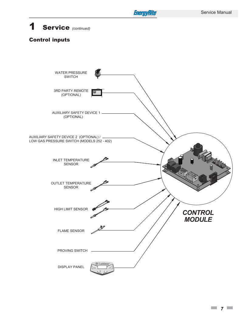
Control module inputs
• Control module inputs and options
Control module outputs
• Control module outputs and options
General
• How the pool heater operates
• How the control module operates
Control panel menu access
• Accessing service and setup mode and locating menus
Maintenance• Service and maintenance schedules
• Inspect pool heater area and pool heater interior
• Check all piping for leaks
• Check air openings
• Flue vent system and air piping
• Check water system
• Check pool heater relief valve (if applicable)
• Inspect ignition electrode
• Check ignition ground wiring
• Check all pool heater wiring
• Check control settings
• Perform start-up and checks
• Check burner flame
• Check flame signal
• General maintenance
• Cleaning heat exchanger
Troubleshooting• Troubleshooting table - No display
• Checking temperature sensors
• Sensor table
• Troubleshooting table - Fault messages displayed on pool heater interface
• Gas manifold pressure adjustment procedure
• Checking gas supply pressure
1 Service
6
Service Manual
The EnergyRite display
1 Service (continued)
Service Manual
7
Control inputs

1 Service
8
Service Manual
Control outputs
1 Service (continued)
Service Manual
9
General Operation
How the pool heater operates
The EnergyRite uses a copper finned tube heat exchangerand an electronic control module. The blower providesboth primary and secondary air to the burners and forcesthe flue products out of the combustion chamber and intothe vent system. The combination gas valve both regulatesthe manifold pressure and provides gas to the manifold,which then supplies the burners. The control and gassupply system is a fixed rate and only performs ON/OFFoperation.
How the control module operates
The EnergyRite control monitors the inlet sensor which isindicative of pool/spa water temperature. The control willbegin an ignition sequence when the water temperature hasdropped below the set point minus the differential. It willalso monitor all safety circuits and will terminate or preventan ignition cycle if a safety circuit is open. In addition, thecontrol will monitor the outlet temperature and willterminate a call for heat if the outlet temperature gets toohigh.

1 Service
10
Service Manual
Access setup menu
Table 1A Use this procedure to access the Setup Menu from the display panel
The pool heater will continue to operate while the Setup Menuis being accessed. To adjust settings, press the MENU buttonuntil the desired screen is displayed. Use the UP and DOWNbuttons to adjust the setting within the screen. By pressing theMENU or POOL/SPA button the new setting will be stored intomemory and the next screen will be displayed.
When adjusting “set passcode” the 4 individual digits can beadjusted. The digit on the far left will be active first. Use the UPand DOWN buttons to adjust the digit. Once the MENUbutton is pushed, that digit is stored into memory and the nextdigit to the right is active. Continue on until all digits have beenadjusted.
After 1 minute of inactivity, all settings are stored and thecontrol will exit the Setup Menu. To manually exit the SetupMenu at any time, press the POOL/SPA button once.
Setup menu descriptions
Pool/spa remote
This setting allows the user to enable or disable the remotecapability of switching from pool to spa. The default setting isdisable.
There are three (3) options under this menu: T Stat, Switch, andDisable.
T Stat - Select this option when the heater is used in conjunction with a two wire remote system which includes itsown thermostat. This option will automatically set the set pointto 104° (max.) and all messages on the display will becomegeneric (i.e. no references to pool or spa). Where there is no callfor heat the pool heater will remain in Standby Mode.
Switch - Select this option when the heater is used inconjunction with a three wire remote system, also known as a three-way switch. The remote will control the pool heater if it isin Pool, Spa, or Standby Mode and will utilize the thermostat onthe heater. When there is no call for Pool or Spa Mode, the poolheater will remain in Standby Mode.
When in T Stat or Switch Mode, the user can turn the control“OFF” by pressing the POOL/SPA button on the display.
Disable - This is the default setting. When this option is selectedthe heater will ignore all inputs on R, Ws, and Wp. The heaterwill not recognize any of the remotes.
For additional wiring instructions consult the third party remotemanufacturer along with the EnergyRite Installation andOperation Manual.
Differential
This setting allows the user to choose how far below set point thewater temperature must drop before the control will initiate acall for heat. The range of adjustment is from 1°F to 15°F. Thedefault setting is 2°F.
Temperature scale
This setting allows the user the choice of showing the displayedtemperature in degrees Fahrenheit or degrees Celsius. Thedefault setting is Fahrenheit.
Restore defaults
This setting allows the user to restore the factory default settingsfor the Setup Menu and temperature settings.
Set passcode
This setting allows the user to set a personal passcode that wouldbe required to lock and unlock the keypad. See Keypad Lockouton page 12 of this manual. The default passcode is 1234.
1 Service (continued)
Service Manual
11
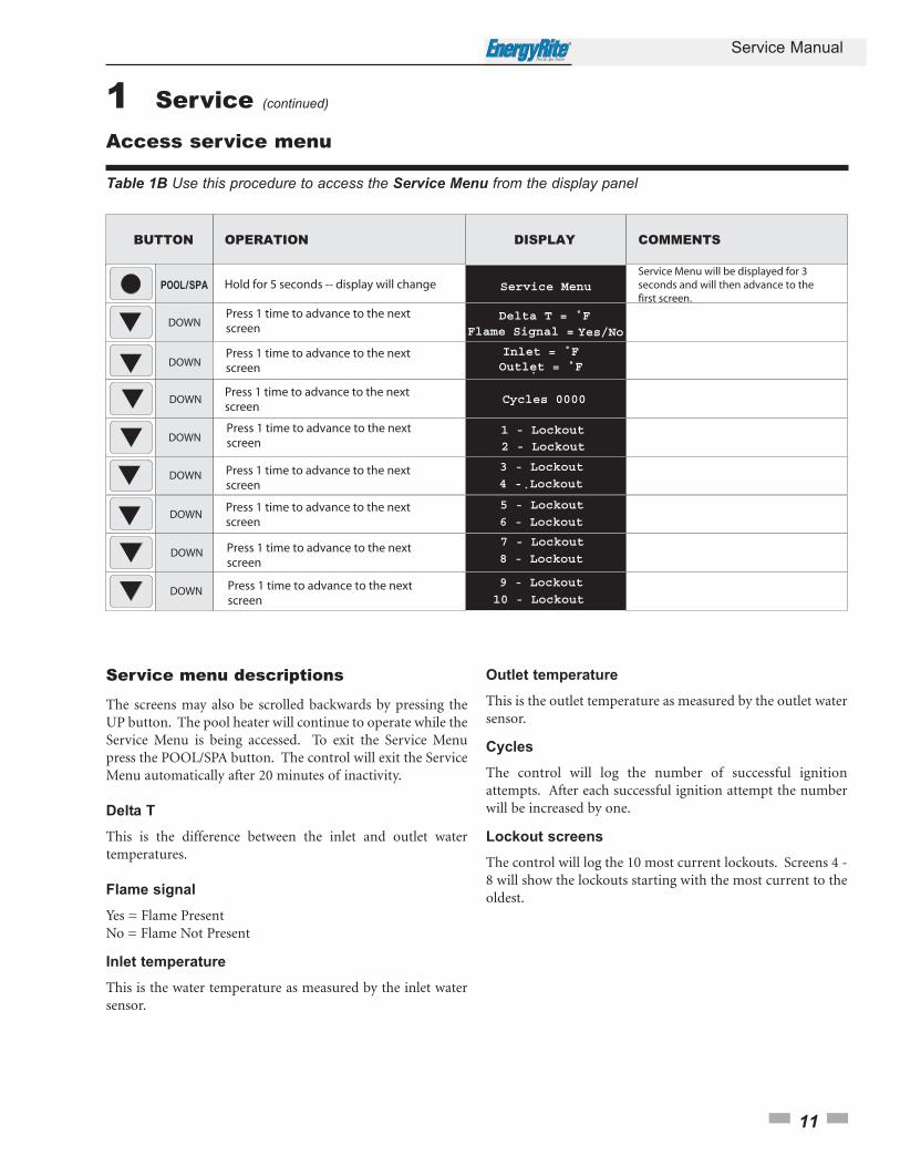
Table 1B Use this procedure to access the Service Menu from the display panel
Service menu descriptions
The screens may also be scrolled backwards by pressing theUP button. The pool heater will continue to operate while theService Menu is being accessed. To exit the Service Menupress the POOL/SPA button. The control will exit the ServiceMenu automatically after 20 minutes of inactivity.
Delta T
This is the difference between the inlet and outlet watertemperatures.
Flame signal
Yes = Flame PresentNo = Flame Not Present
Inlet temperature
This is the water temperature as measured by the inlet watersensor.
Access service menu
Outlet temperature
This is the outlet temperature as measured by the outlet watersensor.
Cycles
The control will log the number of successful ignitionattempts. After each successful ignition attempt the numberwill be increased by one.
Lockout screens
The control will log the 10 most current lockouts. Screens 4 -8 will show the lockouts starting with the most current to theoldest.
1 Service
12
Service Manual
Keypad lockout
Locking the keypad
The user has the ability to lock the keypad to preventunauthorized adjustments. To lock the keypad, the user mustfirst select and input a passcode. See Set Passcode under SetupMenu Descriptions on page 10 of this manual. Once a passcodehas been set, press and hold the UP and DOWN buttonssimultaneously for 5 seconds. The Display Screen will showENTER PASSCODE. The digit on the far left will be blinking.Use the UP and DOWN buttons to adjust the digit. Press theMENU button to advance to the next digit to the right. Use theUP and DOWN buttons to adjust the digit. Press the MENUbutton to advance to the next digit to the right. Repeat thisprocess until all four digits have been set. Once the last digit hasbeen set, press the MENU button.
If the passcode has been entered correctly, the display will showLOCKED for 3 seconds and will then resume normal operation.If the passcode has been entered incorrectly, the display willshow INCORRECT PASSCODE for 3 seconds and will thenreturn to the Passcode Screen for retry. If there is no buttonactivity for 5 seconds the keypad will remain unlocked.
If the keypad has been successfully locked, when any button ispressed, the display will read LOCKED for 5 seconds and willthen resume normal operation.
Unlocking the keypad
Press any button and hold for 5 seconds. The Display Screen willshow ENTER PASSCODE. The digit on the far left will beblinking. Use the UP and DOWN buttons to adjust the digit.Press the MENU button to advance to the next digit to the right.Use the UP and DOWN buttons to adjust the digit. Press theMENU button to advance to the next digit to the right. Repeatthis process until all four digits have been set. Once the last digithas been set, press the MENU button.
If the passcode has been entered correctly the display will showUNLOCKED for 5 seconds and will then resume normaloperation.
If the passcode has been entered incorrectly the display will showINCORRECT PASSCODE for 5 seconds and will then return tothe Passcode Screen for retry. If there is no button activity for5 seconds the keypad will remain locked.
2 Maintenance
Service Manual
13
Maintenance and annual startup
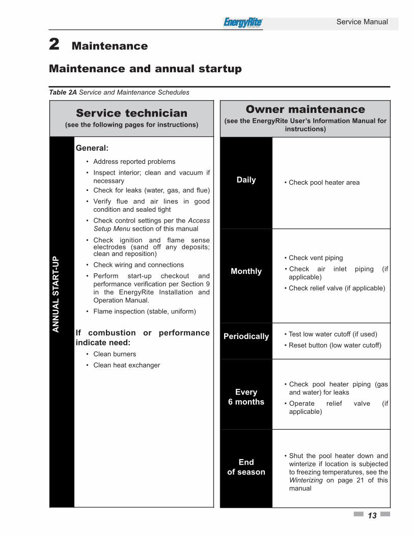
Table 2A Service and Maintenance Schedules
Service technician(see the following pages for instructions)
General:
• Address reported problems
• Inspect interior; clean and vacuum if
necessary
• Check for leaks (water, gas, and flue)
• Verify flue and air lines in good
condition and sealed tight
• Check control settings per the Access Setup Menu section of this manual
• Check ignition and flame sense electrodes (sand off any deposits; clean and reposition)
• Check wiring and connections
• Perform start-up checkout and
performance verification per Section 9
in the EnergyRite Installation and
Operation Manual.
• Flame inspection (stable, uniform)
If combustion or performance
indicate need:
• Clean burners
• Clean heat exchanger
AN
NU
AL
STA
RT-U
P
Owner maintenance(see the EnergyRite User’s Information Manual for
instructions)
Daily • Check pool heater area
Monthly
• Check vent piping
• Check air inlet piping (if
applicable)
• Check relief valve (if applicable)
Periodically • Test low water cutoff (if used)
• Reset button (low water cutoff)
Every
6 months
• Check pool heater piping (gas
and water) for leaks
• Operate relief valve (if
applicable)
End
of season
• Shut the pool heater down and
winterize if location is subjected
to freezing temperatures, see the
Winterizing on page 21 of this
manual
14
Service Manual
Follow the service and maintenance procedures given throughout this manual and in component literatureshipped with the pool heater. Failure to perform the service and maintenance could result in damage to thepool heater or system. Failure to follow the directions in this manual and component literature could resultin severe personal injury, death, or substantial property damage.
The pool heater should be inspected annually only by a qualified service technician. In addition, themaintenance and care of the pool heater designated in Table 2A, Maintenance and Annual Startup sectionand explained on the following pages must be performed to assure maximum pool heater efficiency andreliability. Failure to service and maintain the pool heater and system could result in equipment failure.
Electrical shock hazard – Turn off power to the pool heater before any service operation on the pool heaterexcept as noted otherwise in this instruction manual. Failure to turn off electrical power could result inelectrical shock, causing severe personal injury or death.
�� WARNING
�� WARNING
�� WARNING
Listed in this section are items that must be checked to ensuresafe reliable operations. Verify proper operation after servicing.
1. Examine the venting system at least once a year. Check more often in first year to determine inspection interval.
�� CAUTIONLabel all wires prior to disconnection whenservicing controls. Wiring errors can causeimproper and dangerous operation.
Outdoor Installations - Check vent cap for proper mounting,corrosion or any obstruction of the flue outlet or combustion airinlet.
Indoor Installations - Check all joints and pipe connections fortightness, corrosion or deterioration. Have the entire system,including the venting system, periodically inspected by aqualified service agency.
2 Maintenance
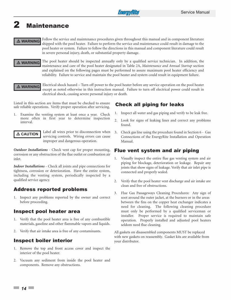
Address reported problems1. Inspect any problems reported by the owner and correct
before proceeding.
Inspect pool heater area1. Verify that the pool heater area is free of any combustible
materials, gasoline and other flammable vapors and liquids.
2. Verify that air intake area is free of any contaminants.
Inspect boiler interior1. Remove the top and front access cover and inspect the
interior of the pool heater.
2. Vacuum any sediment from inside the pool heater andcomponents. Remove any obstructions.
1. Inspect all water and gas piping and verify to be leak free.
2. Look for signs of leaking lines and correct any problemsfound.
3. Check gas line using the procedure found in Section 6 - GasConnections of the EnergyRite Installation and OperationManual.
Check all piping for leaks
Flue vent system and air piping1. Visually inspect the entire flue gas venting system and air
piping for blockage, deterioration or leakage. Repair anyjoints that show signs of leakage. Verify that air inlet pipe isconnected and properly sealed.
2. Verify that the pool heater vent discharge and air intake areclean and free of obstructions.
3. Flue Gas Passageways Cleaning Procedures: Any sign ofsoot around the outer jacket, at the burners or in the areas between the fins on the copper heat exchanger indicates a need for cleaning. The following cleaning procedure must only be performed by a qualified serviceman or installer. Proper service is required to maintain safe operation. Properly installed and adjusted pool heaters seldom need flue cleaning.
All gaskets on disassembled components MUST be replacedwith new gaskets on reassembly. Gasket kits are available fromyour distributor.
Service Manual
15
2 Maintenance (continued)
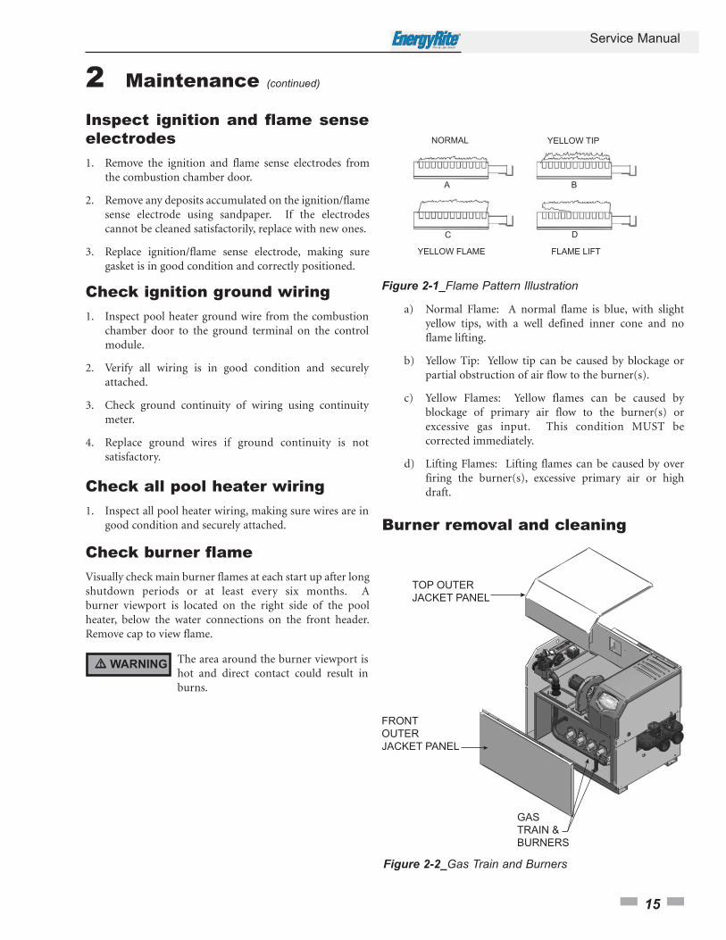
Figure 2-2_Gas Train and Burners
Burner removal and cleaning
�� WARNING The area around the burner viewport ishot and direct contact could result inburns.
Figure 2-1_Flame Pattern Illustration
a) Normal Flame: A normal flame is blue, with slight yellow tips, with a well defined inner cone and no flame lifting.
b) Yellow Tip: Yellow tip can be caused by blockage or partial obstruction of air flow to the burner(s).
c) Yellow Flames: Yellow flames can be caused by blockage of primary air flow to the burner(s) or excessive gas input. This condition MUST be corrected immediately.
d) Lifting Flames: Lifting flames can be caused by over firing the burner(s), excessive primary air or high draft.
Check ignition ground wiring1. Inspect pool heater ground wire from the combustion
chamber door to the ground terminal on the controlmodule.
2. Verify all wiring is in good condition and securelyattached.
3. Check ground continuity of wiring using continuitymeter.
4. Replace ground wires if ground continuity is notsatisfactory.
Check all pool heater wiring1. Inspect all pool heater wiring, making sure wires are in
good condition and securely attached.
Inspect ignition and flame senseelectrodes1. Remove the ignition and flame sense electrodes from
the combustion chamber door.
2. Remove any deposits accumulated on the ignition/flamesense electrode using sandpaper. If the electrodescannot be cleaned satisfactorily, replace with new ones.
3. Replace ignition/flame sense electrode, making suregasket is in good condition and correctly positioned.
Check burner flameVisually check main burner flames at each start up after longshutdown periods or at least every six months. A burner viewport is located on the right side of the poolheater, below the water connections on the front header.Remove cap to view flame.
2 Maintenance
16
Service Manual
�� WARNINGThe combustion chamber lining in thisappliance contains ceramic fiber materials.Ceramic fibers can transform intocristobalite (crystalline silica) when exposedto temperatures above 2192°F (1200°C)dependent upon the length of exposuretime.*
The International Agency for Research onCancer (I.A.R.C.) has concluded,“Crystallinesilica inhaled in the form of quartz orcristobalite from occupational sources iscarcinogenic to humans.”**
Testing has confirmed that the ceramic fibersin this application do not reach 2192°F(1200°C).
*Reference Dyson, D., Butler, M., Hughes, R.,Fisher, R., and Hicks, G. The Devitrificationof Alumino-silicate Ceramic Fiber Materials- The Kinetics of the Formation of DifferentCrystalline Phases, Ann. Occup. Hyg. Vol. 41,No. 55, 1997.
**Reference I.A.R.C. Monograph 68, June1997.
Removal of combustion chamber lining or base
panels:
• Avoid breathing dust and contact with skin and eyes.
• Use NIOSH certified dust respirator (N95)(http://www.cdc.gov/niosh/homepage.html).
• Lightly mist with water (only those areas being handled) the combustion chamber lining or base insulation to prevent airborne fibers.
• Remove combustion chamber lining or base insulation from the pool heater and place it in a plastic bag for disposal.
• Wash potentially contaminated clothes separately from other clothing. Rinse clothes thoroughly.
• NIOSH stated First Aid:Eye: Irrigate immediately.Breathing: Fresh air.
The ceramic fiber material used in thisappliance is an irritant; when handling orreplacing the ceramic materials it is advisablethat the installer follow these safety guides.
NOTICE
1. Burner removal and cleaning procedure:
a) Turn off main power to the pool heater.
b) Turn off main manual gas shutoff to the pool heater.
c) Remove the front and top outer jacket panels.
d) Disconnect the gas supply from the gas valve manifold assembly with a field supplied union before the gas valve. Disconnect the union between the gas valve and the manifold.
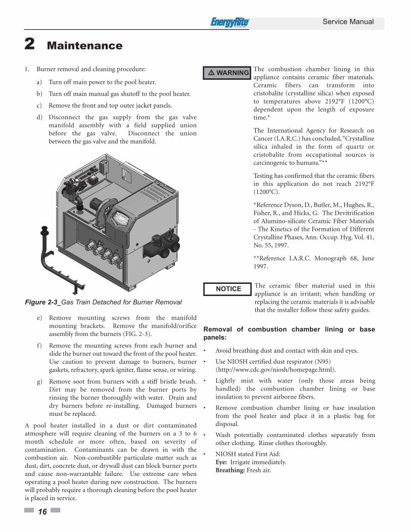
Figure 2-3_Gas Train Detached for Burner Removal
e) Remove mounting screws from the manifold mounting brackets. Remove the manifold/orifice assembly from the burners (FIG. 2-3).
f) Remove the mounting screws from each burner and slide the burner out toward the front of the pool heater.Use caution to prevent damage to burners, burner gaskets, refractory, spark igniter, flame sense, or wiring.
g) Remove soot from burners with a stiff bristle brush.Dirt may be removed from the burner ports by rinsing the burner thoroughly with water. Drain and dry burners before re-installing. Damaged burners must be replaced.
A pool heater installed in a dust or dirt contaminatedatmosphere will require cleaning of the burners on a 3 to 6month schedule or more often, based on severity ofcontamination. Contaminants can be drawn in with thecombustion air. Non-combustible particulate matter such asdust, dirt, concrete dust, or drywall dust can block burner portsand cause non-warrantable failure. Use extreme care whenoperating a pool heater during new construction. The burnerswill probably require a thorough cleaning before the pool heateris placed in service.
Service Manual
17
2 Maintenance (continued)
Do not wet the pool heater’s refractory.NOTICE
2. Combustion Air Fan: The combustion air fan should be checked every 6 months or each season of operation.Clean fan as required when installed in a dust or dirt contaminated location.
3. Water Circulating Pump: Ensure that the filter system pump is providing adequate flow to the pool heater.Backwash and clean filter as required to maintain proper flow.
4. Keep the pool heater area clear and free from combustible materials, gasoline, and other flammable vapors and liquids.
5. Check frequently to be sure the flow of combustion and ventilation air to the pool heater is not obstructed.
6. This pool heater uses a transformer to supply a low voltage control circuit. The voltage on the secondary side should be 24 to 28 VAC when measured with a voltmeter.
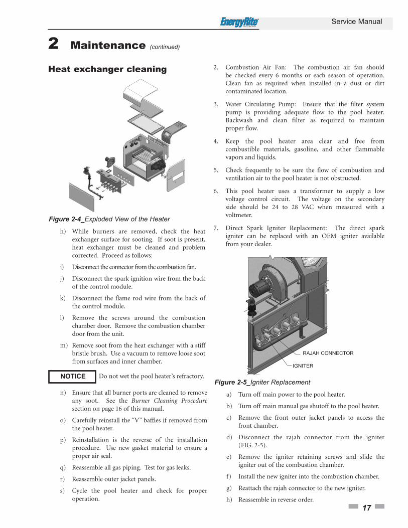
7. Direct Spark Igniter Replacement: The direct spark igniter can be replaced with an OEM igniter available from your dealer.
a) Turn off main power to the pool heater.
b) Turn off main manual gas shutoff to the pool heater.
c) Remove the front outer jacket panels to access the front chamber.
d) Disconnect the rajah connector from the igniter (FIG. 2-5).
e) Remove the igniter retaining screws and slide the igniter out of the combustion chamber.
f) Install the new igniter into the combustion chamber.
g) Reattach the rajah connector to the new igniter.
h) Reassemble in reverse order.
Figure 2-4_Exploded View of the Heater
Heat exchanger cleaning
h) While burners are removed, check the heat exchanger surface for sooting. If soot is present,heat exchanger must be cleaned and problem corrected. Proceed as follows:
i) Disconnect the connector from the combustion fan.
j) Disconnect the spark ignition wire from the back of the control module.
k) Disconnect the flame rod wire from the back ofthe control module.
l) Remove the screws around the combustion chamber door. Remove the combustion chamber door from the unit.
m) Remove soot from the heat exchanger with a stiffbristle brush. Use a vacuum to remove loose soot from surfaces and inner chamber.
n) Ensure that all burner ports are cleaned to remove any soot. See the Burner Cleaning Proceduresection on page 16 of this manual.
o) Carefully reinstall the “V” baffles if removed from the pool heater.
p) Reinstallation is the reverse of the installation procedure. Use new gasket material to ensure a proper air seal.
q) Reassemble all gas piping. Test for gas leaks.
r) Reassemble outer jacket panels.
s) Cycle the pool heater and check for proper operation.
Figure 2-5_Igniter Replacement
18
Service Manual
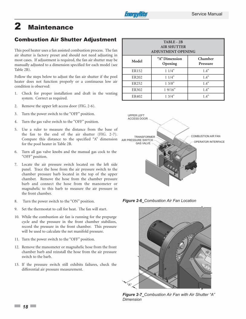
Combustion Air Shutter Adjustment
This pool heater uses a fan assisted combustion process. The fanair shutter is factory preset and should not need adjusting inmost cases. If adjustment is required, the fan air shutter may bemanually adjusted to a dimension specified for each model (seeTable 2B).
Follow the steps below to adjust the fan air shutter if the poolheater does not function properly or a continuous low aircondition is observed:
1. Check for proper installation and draft in the venting system. Correct as required.
2. Remove the upper left access door (FIG. 2-6).
3. Turn the power switch to the “OFF” position.
4. Turn the gas valve switch to the “OFF” position.
5. Use a ruler to measure the distance from the base ofthe fan to the end of the air shutter (FIG. 2-7).Compare this distance to the specified “A” dimension for the pool heater in Table 2B.
6. Turn all gas valve knobs and the manual gas cock to the “OFF” position.
7. Locate the air pressure switch located on the left side panel. Trace the hose from the air pressure switch to the chamber pressure barb located in the top of the upper chamber. Remove the hose from the chamber pressure barb and connect the hose from the manometer or magnahelic to this barb to measure the air pressure in the front chamber.
8. Turn the power switch to the “ON” position.
9. Set the thermostat to call for heat. The fan will start.
10. While the combustion air fan is running for the prepurge cycle and the pressure in the front chamber stabilizes,record the pressure in the front chamber. This pressure will be used to calculate the net manifold pressure.
11. Turn the power switch to the “OFF” position.
12. Remove the manometer or magnahelic hose from the front chamber barb and reinstall the hose from the air pressure switch to the barb.
13. If the pressure switch still exhibits failures, check the differential air pressure measurement.
Figure 2-6_Combustion Air Fan Location
2 Maintenance
"A"
Figure 2-7_Combustion Air Fan with Air Shutter “A”Dimension
TABLE - 2BAIR SHUTTER
ADJUSTMENT OPENING
Model“A” Dimension
OpeningChamberPressure
ER152 1 1/4" 1.4"
ER202 1 1/4" 1.4"
ER252 1 3/8" 1.4"
ER302 1 9/16" 1.4"
ER402 1 3/4" 1.4"
Service Manual
19
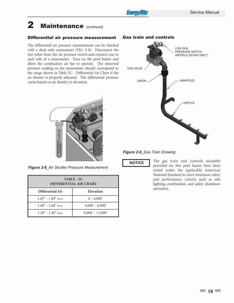
Gas train and controls
)
Figure 2-9_Gas Train Drawing
The gas train and controls assemblyprovided on this pool heater have beentested under the applicable AmericanNational Standard to meet minimum safetyand performance criteria such as safelighting, combustion, and safety shutdownoperation.
NOTICE
2 Maintenance (continued)
Differential air pressure measurement
The differential air pressure measurement can be checkedwith a slack tube manometer (FIG. 2-8). Disconnect thetwo tubes from the air pressure switch and connect one toeach side of a manometer. Turn on the pool heater andallow the combustion air fan to operate. The observedpressure reading on the manometer should correspond tothe range shown in Table 2C - Differential Air Chart if theair shutter is properly adjusted. The differential pressurevaries based on air density at elevation.
TABLE - 2CDIFFERENTIAL AIR CHART
Differential Air Elevation
1.65" - 1.80" w.c. 0 - 4,000'
1.40" - 1.60" w.c. 4,000' - 8,000'
1.20" - 1.40" w.c. 8,000' - 12,000'
Figure 2-8_Air Shutter Pressure Measurement

20
Service Manual
Facts about water chemistryFactors which affect pool and spa water and, more importantly,the efficiency of your new pool/spa heater are:
1. Proper Filtration
2. Proper Circulation
3. Disinfection and Oxidation
4. pH Control and Total Alkalinity
5. Algae Control
The water chemistry of your pool or spa changes daily due tonatural evaporation of the water and the addition of chemicals.Chemicals are used to sanitize and control algae growth in thepool. Their addition must be carefully monitored. If there is animbalance in the pool water chemistry, the minerals in the poolwater will precipitate out and collect in the pool, filter systemand the pool heater. The accumulation of minerals or scale inthe pool heater due to a chemical imbalance will cause a non-warrantable failure of the heat exchanger and its components.
pH is the most important factor in maintaining proper balancein your pool/spa water. pH is the measurement of the acidity oralkalinity of water. The chart in FIG. 2-10 shows the ideal pHrange and what can happen when the pH increases or decreasesfrom the ideal of 7.2 to 7.8.
Figure 2-10_pH Scale
If the pH becomes too high, it lowers the ability of chlorine todestroy bacteria and algae, water can become cloudy, filterelements may become blocked, and scale formation will occur inthe pool and heat exchanger. If the pH becomes too low thewater becomes acid. You can have eye burn and skin irritation,etching of the plaster, corrosion of metal fixtures, and theresulting stains on the plaster, degradation of sand and gravelfilters, and corrosion of the copper tubes in the heat exchanger.Damage to the pool heater due to improper pH isnon-warrantable.
TABLE - 2DRECOMMENDED POOL CHEMISTRY LEVELS
Test Recommended Level
Correct pH 7.2 - 7.8
Chlorine Residual 1.0 - 5.0 ppm
Total Alkalinity 80 - 120 ppm
Calcium Hardness 175 - 350 ppm
Chlorine residual is the chlorine remaining in the pool waterafter it is consumed in the process of destroying bacteria, algae,and other oxidizable materials.
Total alkalinity is the measurement of the total amount ofalkaline chemicals in the water. Alkalinity controls pH. Sodiumbicarbonate is used to raise total alkalinity.
Calcium hardness can be raised by the addition of calciumchloride, and lowered by the addition of Tri-sodium Phosphateor its equivalent.
The corrosive level of pool water can also be measured by theLanglier Saturation Index. This index is calculated by a formulawhich uses operating temperatures, total alkalinity, pH, calciumhardness and total dissolved solids. The optimum SaturationIndex value is zero. A negative value indicates a corrosivecondition. Your pool/spa dealer can provide additional data andequipment to make this measurement if a problem exists.
2 MaintenanceWe recommend using a four-way test kit to monitor thefollowing levels (see Table 2D) to ensure proper operation ofyour pool heater:
Service Manual
21
Heat exchanger inspectionTubes
This pool heater is especially designed to operate withoutaccumulation of scale in the heat exchanger, even in veryhard water. Periodic inspections of the tubes should bemade to be sure that no scale is accumulating. Water pipingshould be disconnected at the flanges. The front header canbe removed to inspect the tubes. A scale deposit of paperthickness is normal. Heavier deposits should be cleanedout.
If scale is found in the tubes, THE CAUSE SHOULD BEFOUND AND CORRECTED. Removal and cleaning of theheat exchanger must be performed by a qualifiedserviceman or installer.
The probable cause is improper water chemistry. Check thefollowing possible causes:
1. High pH.
2. Improper adjustment of an external bypass.
3. Inadequate pump flow.
Always be sure that the filter pump is in good operatingcondition and runs continuously when the pool heater is inoperation.
Prevention of freezingHeat exchangers and headers damaged by freezing are notcovered by warranty. If equipment is subject to freezingtemperatures, the following precautions must be observed.
Winterizing
Although this pool heater is CSA design certified foroutdoor installations, such installations are notrecommended in areas where the pool heater will beoperated in the winter months and the danger of freezingexists. Proper freeze protection must be provided foroutdoor installations, pool heaters installed in unheatedequipment rooms or where temperatures may drop to thefreezing point or lower. If freeze protection is not providedfor the system, a low ambient temperature alarm isrecommended for the equipment room. Damage to thepool heater by freezing is non-warrantable.
1. Pump Operation - MOST IMPORTANT - This pool heater is designed for continuous operation of the filter system pump when the burners are firing. If the system pump does not run continuously an additional pump must be installed to provide constant circulation through the pool heater. The constant flow of warm pool water can help prevent freezing.
2. Location - Indoor pool heaters must be located in a room having a temperature safely above freezing [32°F(0°C)].
3. Caution - An equipment room operating under a negative pressure may experience a downdraft in the flue of a pool heater which is not firing. The cold outside air pulled down the flue may freeze a heat exchanger. This condition must be corrected to provide adequate freeze protection.
4. Outdoor Pool Heater Installation - Use extreme caution to prevent freezing. A snow screen should be installed to prevent snow and ice accumulation around the pool heater or its venting system.
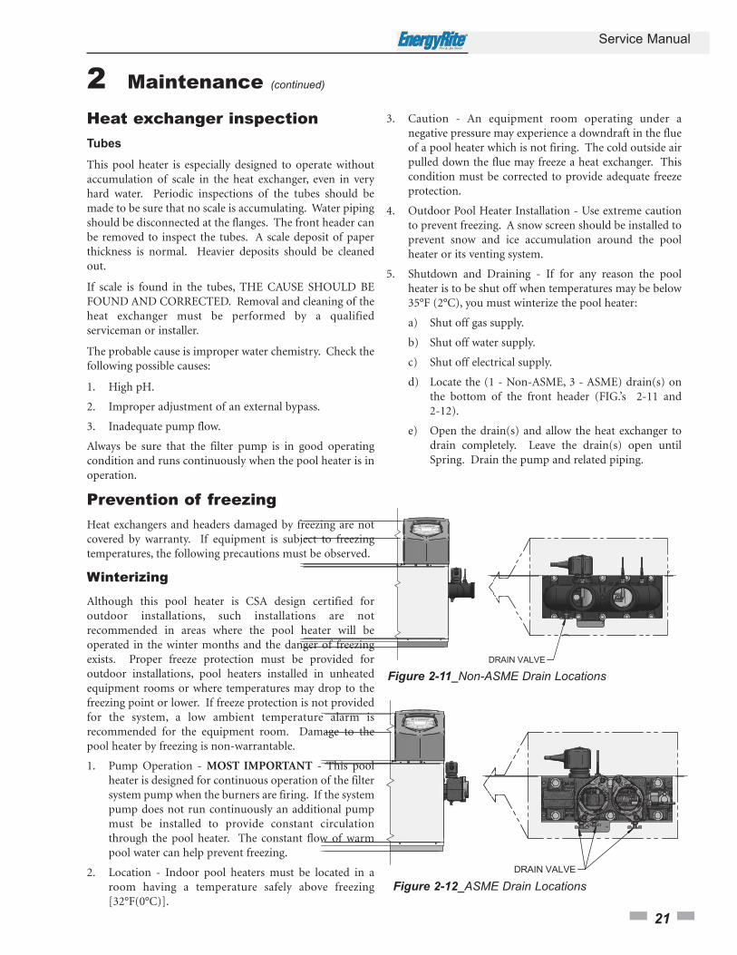
5. Shutdown and Draining - If for any reason the pool heater is to be shut off when temperatures may be below 35°F (2°C), you must winterize the pool heater:
a) Shut off gas supply.
b) Shut off water supply.
c) Shut off electrical supply.
d) Locate the (1 - Non-ASME, 3 - ASME) drain(s) on the bottom of the front header (FIG.’s 2-11 and 2-12).
e) Open the drain(s) and allow the heat exchanger to drain completely. Leave the drain(s) open until Spring. Drain the pump and related piping.
Figure 2-11_Non-ASME Drain Locations
Figure 2-12_ASME Drain Locations
2 Maintenance (continued)
3 Troubleshooting
22
Service Manual
Label all wires prior to disconnection whenservicing controls. Wiring errors can causeimproper and dangerous operation. Alwaysdisconnect power to the pool heater beforeservicing. Failure to comply could result insevere personal injury, death, or substantialproperty damage.
Never jumper (bypass) any device except formomentary testing as outlined in theTroubleshooting chart. Severe personalinjury, death, or substantial property damagecan result.
Before troubleshooting:1. Have the following items:
a. Voltmeter that can check 120 VAC, 240 VAC, 24 VAC,and 12 VDC.
b. Continuity checker.c. Contact thermometer.
2. Check for 240 VAC (120 VAC optional) to pool heater.
3. Make sure all external limit controls are installed andoperating.
�� WARNING
�� WARNING
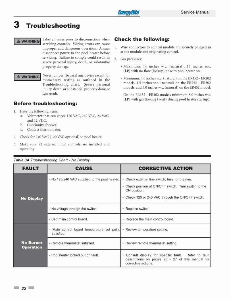
Table 3A Troubleshooting Chart - No Display
FFAAUULLTT CCAAUUSSEE CCOORRRREECCTTIIVVEE AACCTTIIOONN
No Display
- No 120/240 VAC supplied to the pool heater. • Check external line switch, fuse, or breaker.
• Check position of ON/OFF switch. Turn switch to the
ON position.
• Check 120 or 240 VAC through the ON/OFF switch.
- No voltage through the switch. • Replace switch.
- Bad main control board. • Replace the main control board.
No BurnerOperation
- Main control board temperature set point
satisfied.
• Review temperature setting.
- Remote thermostat satisfied. • Review remote thermostat setting.
- Pool heater locked out on fault. • Consult display for specific fault. Refer to fault
descriptions on pages 25 - 27 of this manual for
corrective actions.
Check the following:1. Wire connectors to control module are securely plugged in
at the module and originating control.
2. Gas pressures:
• Maximum: 14 inches w.c. (natural), 14 inches w.c.(LP) with no flow (lockup) or with pool heater on.
• Minimum: 4.0 inches w.c. (natural) on the ER152 - ER202 models, 4.5 inches w.c. (natural) on the ER252 - ER302 models, and 5.0 inches w.c. (natural) on the ER402 model.
On the ER152 - ER402 models minimum 8.0 inches w.c.(LP) with gas flowing (verify during pool heater startup).

Table 3B Inlet/Outlet System Sensor Resistance vs. Temperature
Temperature Resistance
50 18,780
68 12,263
86 8,194
104 5,592
122 3,893
140 2,760
Checking temperature sensors
The pool heater temperature sensors (inlet and outlet water) are both resistance type devices. The following table shows thecorrect values for the sensors at various temperatures. Use an ohmmeter to read the resistance of the sensor at a knowntemperature. If the resistance of the sensor does not closely match, replace the sensor.
3 Troubleshooting (continued)
Service Manual
23

3 Troubleshooting
24
Service Manual
Table 3C Troubleshooting Chart - Noisy System
FFAAUULLTT CCAAUUSSEE CCOORRRREECCTTIIVVEE AACCTTIIOONN
NoisyOperation
- Supply gas problem. Natural gas pressures
should be between 4.0 inches w.c. and
14 inches w.c. LP gas pressures should
be between 8.0 inches w.c. and
14 inches w.c.
• Refer to Section 6 - Gas Connections of the EnergyRite
Installation and Operation Manual for detailed
information concerning the gas supply.
- Dirty / damaged burners. • Refer to page 16 in this manual for the burner removal
and inspection procedure. Clean or replace the burner
as necessary.
- Low water flow through the heat exchanger. • Refer to Section 7 - Water Connections of the
EnergyRite Installation and Operation Manual for
minimum flow rates. Verify the pool heater pump is
running on a call for heat.
- Air in the piping system. • Properly purge all air from the piping system.
Relief ValveOpening
- System pressure exceeds relief valve
setting.
• Lower the system pressure below the 50 PSI rating of
the supplied relief valve or replace the standard relief
valve with a higher rated valve up to the maximum
pressure of the heat exchanger.

Service Manual
25
Table 3D Troubleshooting Chart - Fault Messages Displayed on Pool Heater Interface
FFAAUULLTT DDEESSCCRRIIPPTTIIOONN CCOORRRREECCTTIIVVEE AACCTTIIOONN
AUX Device 1Open
The field supplied safety wired into AUX
Device 1 has opened. This will most
commonly be a flow switch or low water
cutoff.
• Check pool heater pump operation on a call for heat.
• Check for closed valves or obstructions in the pool
heater piping.
• Verify system is full of water and all air has been
purged from the system.
• Check for loose or misplaced jumpers if flow switch
or LWCO is not installed.
• If other safety device, ensure device is working
properly and conditions are accurate.
FlameSequence
(will require a manualreset once the condition
has been corrected.Press the RESET buttonon the display to reset.)
The flame detector circuit is seeing a flame
signal while no flame is present.
• Check supply voltage for proper polarity.
• Check external wiring for voltage feedback.
• Check the flame rod and make sure it is clean.
• Check the internal wiring for bad connections.
• Replace main control board.
Ignition Failure(will require a manual
reset once the conditionhas been corrected.
Press the RESET buttonon the display to reset.)
The pool heater has failed to prove main
burner ignition after four (4) attempts.
• Check for proper electrical grounding of the pool
heater.
• Check incoming supply gas pressure. Natural gas
pressures should be between 4.0 - 14 inches w.c.
and LP gas pressures should be between 8.0 -
14 inches w.c. Refer to Section 6 - Gas Connections
of the EnergyRite Installation and Operation Manual
for detailed information concerning the gas supply.
• Verify that the outdoor vent cap or vent/air intake
pipes are installed correctly and that there are no
obstructions.
• Check for 24 VAC to the gas valve.
• If 24 VAC is present at the main control board, check
the wiring between the main control board and the
gas valve. Replace the wiring if necessary.
• If 24 VAC is present, check the outlet of the valve to
ensure the valve is flowing gas. With a manometer
connected to the outlet tap of the gas valve there
should be very little pressure during pre-purge.
Once the ignition begins, the pressure should jump
to around 3 inches. If this sudden change does not
happen then the valve is not opening.
• Inspect the burner. Reference page 16 of this
manual for removal and cleaning procedures.
Replace if necessary.
• Replace the main control board.
3 Troubleshooting (continued)
3 Troubleshooting
26
Service Manual
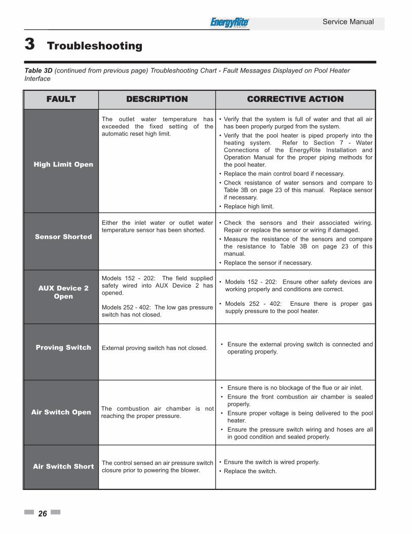
Table 3D (continued from previous page) Troubleshooting Chart - Fault Messages Displayed on Pool HeaterInterface
FFAAUULLTT DDEESSCCRRIIPPTTIIOONN CCOORRRREECCTTIIVVEE AACCTTIIOONN
High Limit Open
The outlet water temperature has
exceeded the fixed setting of the
automatic reset high limit.
• Verify that the system is full of water and that all air
has been properly purged from the system.
• Verify that the pool heater is piped properly into the
heating system. Refer to Section 7 - Water
Connections of the EnergyRite Installation and
Operation Manual for the proper piping methods for
the pool heater.
• Replace the main control board if necessary.
• Check resistance of water sensors and compare to
Table 3B on page 23 of this manual. Replace sensor
if necessary.
• Replace high limit.
Sensor Shorted
Either the inlet water or outlet water
temperature sensor has been shorted.
• Check the sensors and their associated wiring.
Repair or replace the sensor or wiring if damaged.
• Measure the resistance of the sensors and compare
the resistance to Table 3B on page 23 of this
manual.
• Replace the sensor if necessary.
AUX Device 2Open
Models 152 - 202: The field supplied
safety wired into AUX Device 2 has
opened.
Models 252 - 402: The low gas pressure
switch has not closed.
• Models 152 - 202: Ensure other safety devices are
working properly and conditions are correct.
• Models 252 - 402: Ensure there is proper gas
supply pressure to the pool heater.
Proving Switch External proving switch has not closed.• Ensure the external proving switch is connected and
operating properly.
Air Switch Open The combustion air chamber is not
reaching the proper pressure.
• Ensure there is no blockage of the flue or air inlet.
• Ensure the front combustion air chamber is sealed
properly.
• Ensure proper voltage is being delivered to the pool
heater.
• Ensure the pressure switch wiring and hoses are all
in good condition and sealed properly.
Air Switch Short The control sensed an air pressure switch
closure prior to powering the blower.
• Ensure the switch is wired properly.
• Replace the switch.

3 Troubleshooting (continued)
Service Manual
27
Table 3D (continued from previous page) Troubleshooting Chart - Fault Messages Displayed on Pool HeaterInterface
FFAAUULLTT DDEESSCCRRIIPPTTIIOONN CCOORRRREECCTTIIVVEE AACCTTIIOONN
Pool Standby /Low Water Flow
The pool heater has a call for heat, but
there is insufficient water flow.
• Verify that the system is full of water and that all air
has been properly purged from the system.
• Verify that the pool heater is piped properly into the
heating system. Reference Section 7 - Water
Connections in the EnergyRite Installation and
Operation Manual for the proper piping methods for
the pool heater.
• Replace the switch.
Outlet SensorOpen
The control does not sense the presence
of an outlet sensor.
• Ensure proper wiring of the outlet sensor.
• Replace the sensor.
• Replace the main control board.
Inlet Sensor Open The control does not sense the presence
of an inlet sensor.
• Ensure proper wiring of the inlet sensor.
• Replace the sensor.
• Replace the main control board.
Outlet TempExceeded
The outlet temperature has exceeded the
maximum allowable outlet temperature.
• Verify that the system is full of water and that all air
has been properly purged from the system.
• Verify that the pool heater is piped properly into
the heating system. Reference Section 7 - Water
Connections in the EnergyRite Installation and
Operation Manual for the proper piping methods
for the pool heater.
• Measure the resistance of the sensors and
compare the resistance to Table 3B on page 23 of
this manual.
• Replace the sensor if necessary.
Lockout / LowWater Flow
The pool heater sensed low water pressure
while the pool heater was running.
• Verify that the system is full of water and that all air
has been properly purged from the system.
• Verify that the pool heater is piped properly into
the heating system. Reference Section 7 - Water
Connections in the EnergyRite Installation and
Operation Manual for the proper piping methods
for the pool heater.
Button Malfunction One of the buttons has malfunctioned. • Replace the board.
3 Troubleshooting
28
Service Manual
Gas manifold pressure adjustmentprocedure
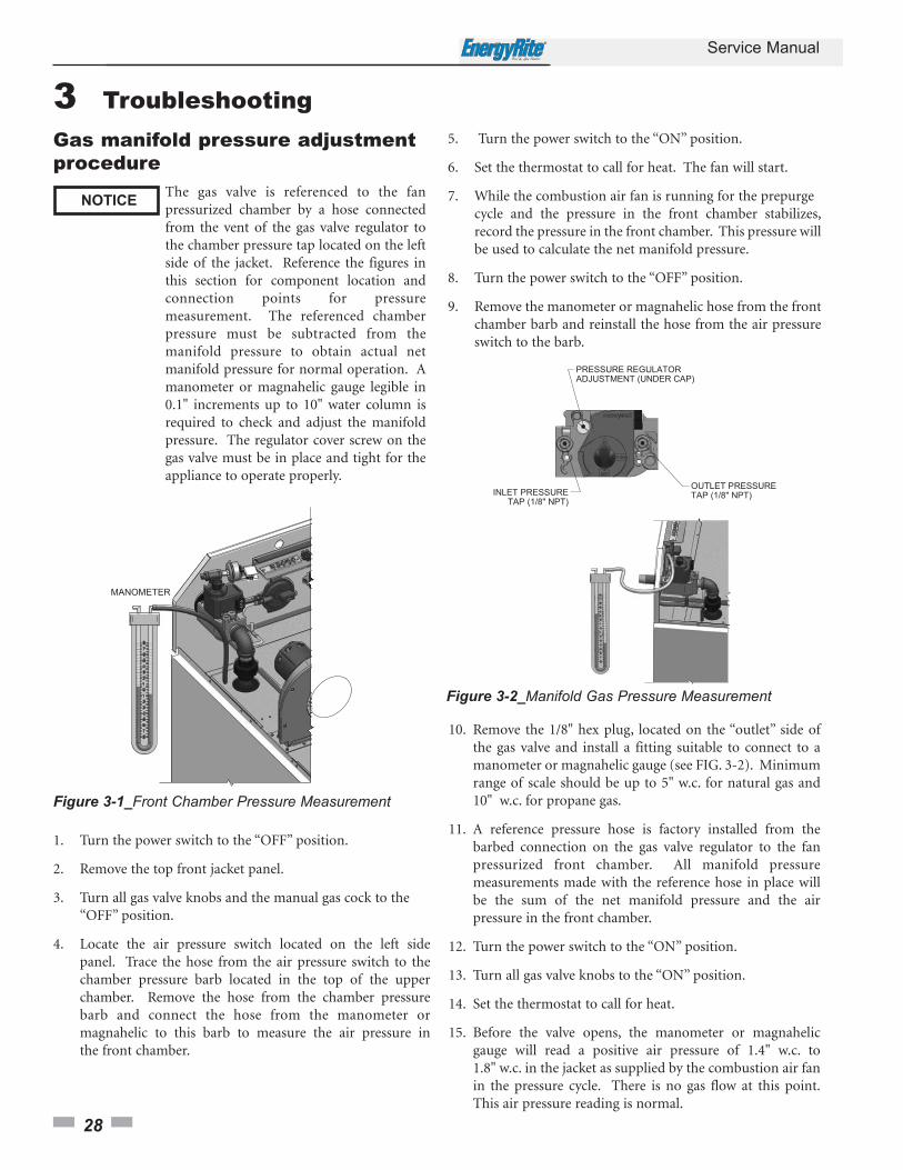
Figure 3-1_Front Chamber Pressure Measurement
5. Turn the power switch to the “ON” position.
6. Set the thermostat to call for heat. The fan will start.
7. While the combustion air fan is running for the prepurge cycle and the pressure in the front chamber stabilizes,record the pressure in the front chamber. This pressure will be used to calculate the net manifold pressure.
8. Turn the power switch to the “OFF” position.
9. Remove the manometer or magnahelic hose from the front chamber barb and reinstall the hose from the air pressure switch to the barb.
Figure 3-2_Manifold Gas Pressure Measurement
NOTICEThe gas valve is referenced to the fanpressurized chamber by a hose connectedfrom the vent of the gas valve regulator tothe chamber pressure tap located on the leftside of the jacket. Reference the figures inthis section for component location andconnection points for pressuremeasurement. The referenced chamberpressure must be subtracted from themanifold pressure to obtain actual netmanifold pressure for normal operation. Amanometer or magnahelic gauge legible in0.1" increments up to 10" water column isrequired to check and adjust the manifoldpressure. The regulator cover screw on thegas valve must be in place and tight for theappliance to operate properly.
1. Turn the power switch to the “OFF” position.
2. Remove the top front jacket panel.
3. Turn all gas valve knobs and the manual gas cock to the “OFF” position.
4. Locate the air pressure switch located on the left side panel. Trace the hose from the air pressure switch to the chamber pressure barb located in the top of the upper chamber. Remove the hose from the chamber pressure barb and connect the hose from the manometer or magnahelic to this barb to measure the air pressure in the front chamber.
10. Remove the 1/8" hex plug, located on the “outlet” side ofthe gas valve and install a fitting suitable to connect to a manometer or magnahelic gauge (see FIG. 3-2). Minimum range of scale should be up to 5" w.c. for natural gas and 10" w.c. for propane gas.
11. A reference pressure hose is factory installed from the barbed connection on the gas valve regulator to the fan pressurized front chamber. All manifold pressure measurements made with the reference hose in place will be the sum of the net manifold pressure and the air pressure in the front chamber.
12. Turn the power switch to the “ON” position.
13. Turn all gas valve knobs to the “ON” position.
14. Set the thermostat to call for heat.
15. Before the valve opens, the manometer or magnahelic gauge will read a positive air pressure of 1.4" w.c. to 1.8" w.c. in the jacket as supplied by the combustion air fan in the pressure cycle. There is no gas flow at this point.This air pressure reading is normal.
Service Manual
29
3 Troubleshooting (continued)
16. The gas valve will open at the end of the trial for ignition stage and remain open as the burners fire.Observe the gas manifold pressure when valves open.If insufficient gas pressure is supplied to the burners,the burners will not fire. Record the gas pressure indicated on the manometer or magnahelic. Subtract the air pressure in the front chamber (as recorded in Step 7) from the gross manifold pressure observed at the end of trial for ignition and when the burners are firing. The gross manifold pressure will typically be within the range of 3.0" w.c. to 3.5" w.c. for Natural Gas and 5.8" w.c. to 6.3" w.c. for LP Gas at full fire. The difference in the gross manifold pressure and the front chamber pressure is the net manifold pressure setting of the gas valve’s regulator. Compare the net setting to the setting specified for the type of gas used. Adjust regulator as required. Set the thermostat to a setting lower than the appliance’s water temperature to turn the burners off. Allow appliance to run through the post purge sequence. Turn the power switch to the “OFF” position.
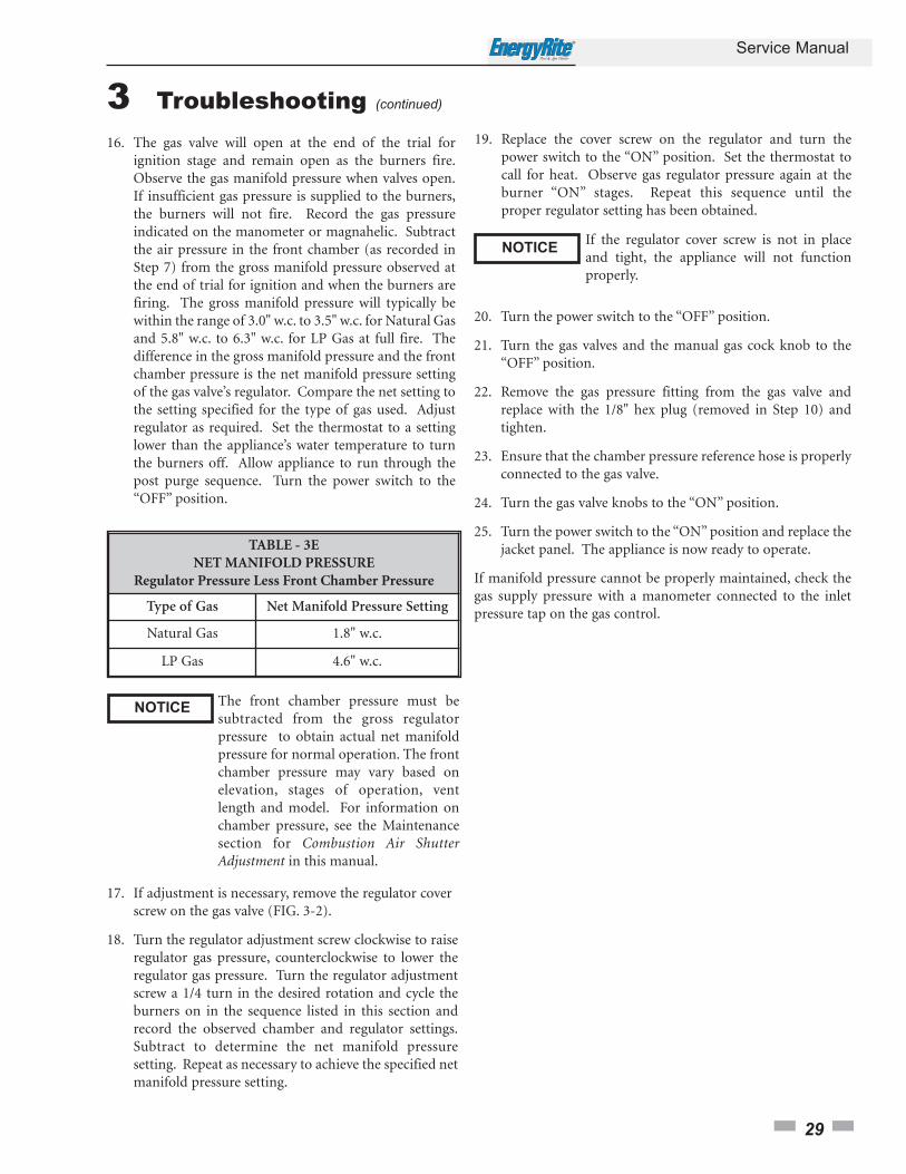
TABLE - 3ENET MANIFOLD PRESSURE
Regulator Pressure Less Front Chamber Pressure
Type of Gas Net Manifold Pressure Setting
Natural Gas 1.8" w.c.
LP Gas 4.6" w.c.
NOTICEThe front chamber pressure must besubtracted from the gross regulatorpressure to obtain actual net manifoldpressure for normal operation. The frontchamber pressure may vary based onelevation, stages of operation, ventlength and model. For information onchamber pressure, see the Maintenancesection for Combustion Air ShutterAdjustment in this manual.
19. Replace the cover screw on the regulator and turn the power switch to the “ON” position. Set the thermostat to call for heat. Observe gas regulator pressure again at the burner “ON” stages. Repeat this sequence until the proper regulator setting has been obtained.
NOTICEIf the regulator cover screw is not in placeand tight, the appliance will not functionproperly.
20. Turn the power switch to the “OFF” position.
21. Turn the gas valves and the manual gas cock knob to the “OFF” position.
22. Remove the gas pressure fitting from the gas valve and replace with the 1/8" hex plug (removed in Step 10) and tighten.
23. Ensure that the chamber pressure reference hose is properly connected to the gas valve.
24. Turn the gas valve knobs to the “ON” position.
25. Turn the power switch to the “ON” position and replace the jacket panel. The appliance is now ready to operate.
If manifold pressure cannot be properly maintained, check thegas supply pressure with a manometer connected to the inletpressure tap on the gas control.
17. If adjustment is necessary, remove the regulator cover screw on the gas valve (FIG. 3-2).
18. Turn the regulator adjustment screw clockwise to raise regulator gas pressure, counterclockwise to lower the regulator gas pressure. Turn the regulator adjustment screw a 1/4 turn in the desired rotation and cycle the burners on in the sequence listed in this section and record the observed chamber and regulator settings.Subtract to determine the net manifold pressure setting. Repeat as necessary to achieve the specified net manifold pressure setting.
Service Manual
30
3 Troubleshooting
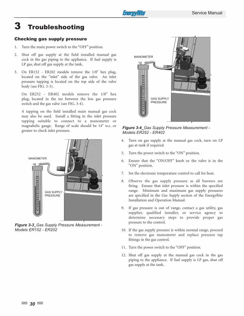
4. Turn on gas supply at the manual gas cock, turn on LP gas at tank if required.
5. Turn the power switch to the “ON” position.
6. Ensure that the “ON/OFF” knob or the valve is in the “ON” position.
7. Set the electronic temperature control to call for heat.
8. Observe the gas supply pressure as all burners are firing. Ensure that inlet pressure is within the specified range. Minimum and maximum gas supply pressures are specified in the Gas Supply section of the EnergyRite Installation and Operation Manual.
9. If gas pressure is out of range, contact a gas utility, gas supplier, qualified installer, or service agency to determine necessary steps to provide proper gas pressure to the control.
10. If the gas supply pressure is within normal range, proceed to remove gas manometer and replace pressure tap fittings in the gas control.
11. Turn the power switch to the “OFF” position.
12. Shut off gas supply at the manual gas cock in the gas piping to the appliance. If fuel supply is LP gas, shut offgas supply at the tank.
Figure 3-4_Gas Supply Pressure Measurement -Models ER252 - ER402
Checking gas supply pressure
1. Turn the main power switch to the “OFF” position.
2. Shut off gas supply at the field installed manual gas cock in the gas piping to the appliance. If fuel supply is LP gas, shut off gas supply at the tank.
3. On ER152 - ER202 models remove the 1/8" hex plug,located on the “inlet” side of the gas valve. An inlet pressure tapping is located on the top side of the valve body (see FIG. 3-3).
On ER252 - ER402 models remove the 1/8" hex plug, located in the tee between the low gas pressure switch and the gas valve (see FIG. 3-4).
A tapping on the field installed main manual gas cock may also be used. Install a fitting in the inlet pressure tapping suitable to connect to a manometer or magnahelic gauge. Range of scale should be 14" w.c. or greater to check inlet pressure.
Figure 3-3_Gas Supply Pressure Measurement -Models ER152 - ER202
31
Upon completion of any testing on the gassystem, leak test all gas connections with asoap and water solution while main burnersare operating. Do not spray soap and watersolution on the housing. The use of anexcessive amount of soap and water solutioncan damage the control. Immediately repairany leak found in the gas train or relatedcomponents. Do not operate an appliancewith a leak in the gas train, valves, or relatedpiping.
NOTICE
Check burner performance by cycling the system while youobserve burner response. Burners should ignite promptly.Flame pattern should be stable, see the Maintenance NormalFlame Pattern section. Turn system off and allow burners tocool, then cycle burners again to ensure proper ignition andflame characteristics.
13. Remove the manometer and related fittings from the “inlet” side of the gas valve, replace the 1/8" hex plug in the tee (Models ER252 - ER402) or gas valve (Models ER152 - ER202) and tighten.
14. Turn on the gas supply at the manual valve, turn on the LP gas at the tank if required.
15. Turn the power switch to the “ON” position.
16. Ensure that the “ON/OFF” knob or the valve is in the “ON” position.
17. Set the electronic temperature control to call for heat.
If proper ignition and burner operation is not achieved afterchecking gas supply pressure and setting the correct netmanifold pressure, see the Maintenance section for CombustionAir Shutter Adjustment in this manual. Follow the procedure toadjust the combustion air fan.
Service Manual
3 Troubleshooting (continued)

ERP-SER-Rev ACP-2M-3/07