service manual s6 gsm / pcndiagramasde.com/diagramas/telefonos/siemens - sm_s6_lvl2...service manual...
TRANSCRIPT
Private Communication Systems
Mobile Phones
V1.3 1 PN MP ST D. Schnoor 10/97
Service Manual
S6 GSM / PCN
V 1.3
Total number of pages: 31

Private Communication Systems
Mobile Phones
V1.3 2 PN MP ST D. Schnoor 10/97
1 Table of Contents
1 TABLE OF CONTENTS....................................................................................................................................2
2 TECHNICAL DATA..........................................................................................................................................3
3 GENERAL INFORMATION ............................................................................................................................4
4 MECHANICAL CONCEPT..............................................................................................................................4
4.1 S6 GSM / PCN MECHANICAL DRAWINGS ............................................................................................................5
4.2 DISASSEMBLING THE S6......................................................................................................................................7
4.3 ASSEMBLING THE S6...........................................................................................................................................7
4.4 BOARD VERSIONS ...............................................................................................................................................8
4.5 UPPER CASE PROTECTION .................................................................................................................................10
4.6 HANDSET DATECODES ......................................................................................................................................10
5 HARDWARE CONCEPT................................................................................................................................11
5.1 BLOCK DIAGRAM ..............................................................................................................................................11
5.2 HARDWARE DESCRIPTION.................................................................................................................................13
5.3 POWER SUPPLY CONCEPT .................................................................................................................................14
5.4 OVERVOLTAGE CONDITIONS .............................................................................................................................15
6 S6 GSM / PCN SOFTWARE OPTIONS ........................................................................................................16
7 SOFTWARE PROGRAMMING ....................................................................................................................20
7.1 DESCRIPTION OF SOFTWARE BOOTING...............................................................................................................21
7.2 LANGUAGE GROUPS..........................................................................................................................................21
8 DEBLOCKING.................................................................................................................................................22
9 BATTERY .........................................................................................................................................................23
9.1 SPECIFICATION..................................................................................................................................................23
9.2 SHORT CIRCUIT PROTECTION ............................................................................................................................24
9.3 DEEP DISCHARGE..............................................................................................................................................25
9.4 BATTERY DATECODES ......................................................................................................................................25
10 S6 GSM / PCN ACCESSORIES....................................................................................................................25
10.1 DESKTOP CHARGER ........................................................................................................................................27
10.2 CAR CHARGER ................................................................................................................................................27
10.3 CAR KIT BASIC ...............................................................................................................................................27
10.4 CAR KIT HANDSFREE ......................................................................................................................................27
11 SPARE PARTS LIST .....................................................................................................................................28
11.1 SWAP UNITS.....................................................................................................................................................29
11.2 SPARE PARTS ...................................................................................................................................................29
11.3 CUSTOMER SPEZIFIED SPARE PARTS .................................................................................................................30
11.4 ACCESSORIES AND WEARING PARTS ................................................................................................................30
11.5 DOCUMENTATION ...........................................................................................................................................31

Private Communication Systems
Mobile Phones
V1.3 3 PN MP ST D. Schnoor 10/97
2 Technical Data
Length 159 mm Width 55 mm Thickness 16/22 mm Volume 155 cm³ Weight 165 g Performance: GSM class 4 (2 Watt) PCN class 1 (1 Watt) Powersupply: Lithium Ion battery (3,6V/1000mAh) Standby time: up to 30 hours Talk time: Up to 4 hours. Carging Time: Full charge in 2.5 hours Display LCD high-resolution graphic display, 97 x 33 pixels, 4 rows of 16 characters SIM Card Type: Small (plug in) 3V or 5V
Private Communication Systems
Mobile Phones
V1.3 4 PN MP ST D. Schnoor 10/97
3 General Information
The S6 is the first model of a whole new handset generation in 3 Volt technology. It comes either as a GSM or a PCN version.
4 Mechanical Concept
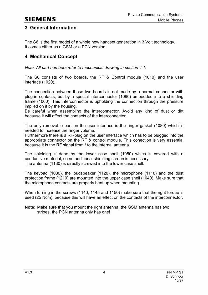
Note: All part numbers refer to mechanical drawing in section 4.1! The S6 consists of two boards, the RF & Control module (1010) and the user interface (1020). The connection between those two boards is not made by a normal connector with plug-in contacts, but by a special interconnector (1090) embedded into a shielding frame (1060). This interconnector is upholding the connection through the pressure implied on it by the housing. Be careful when assembling the interconnector. Avoid any kind of dust or dirt because it will affect the contacts of the interconnector. The only removable part on the user interface is the ringer gasket (1080) which is needed to increase the ringer volume. Furthermore there is a RF-plug on the user interface which has to be plugged into the appropriate connector on the RF & control module. This conection is very essential because it is the RF signal from / to the internal antenna.
The shielding is done by the lower case shell (1050) which is covered with a conductive material, so no additional shielding screen is necessary. The antenna (1130) is directly screwed into the lower case shell. The keypad (1030), the loudspeaker (1120), the microphone (1110) and the dust protection frame (1210) are mounted into the upper case shell (1040). Make sure that the microphone contacts are properly bent up when mounting. When turning in the screws (1140, 1145 and 1150) make sure that the right torque is used (25 Ncm), because this will have an effect on the contacts of the interconnector.
Note: Make sure that you mount the right antenna, the GSM antenna has two stripes, the PCN antenna only has one!

Private Communication Systems
Mobile Phones
V1.3 5 PN MP ST D. Schnoor 10/97
4.1 S6 GSM / PCN mechanical drawings
Figure 1: Mechanical Drawing S6
Private Communication Systems
Mobile Phones
V1.3 6 PN MP ST D. Schnoor 10/97
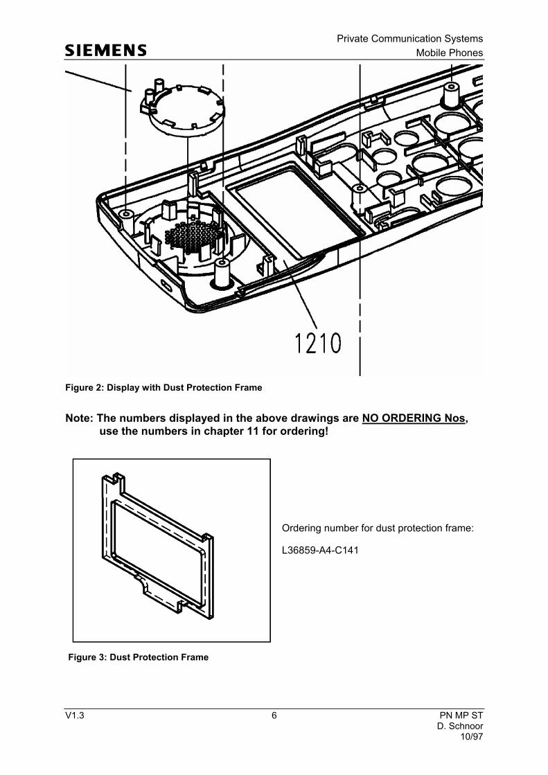
Note: The numbers displayed in the above drawings are NO ORDERING Nos,
use the numbers in chapter 11 for ordering!
Ordering number for dust protection frame:
L36859-A4-C141
Figure 2: Display with Dust Protection Frame
Figure 3: Dust Protection Frame
Private Communication Systems
Mobile Phones
V1.3 7 PN MP ST D. Schnoor 10/97
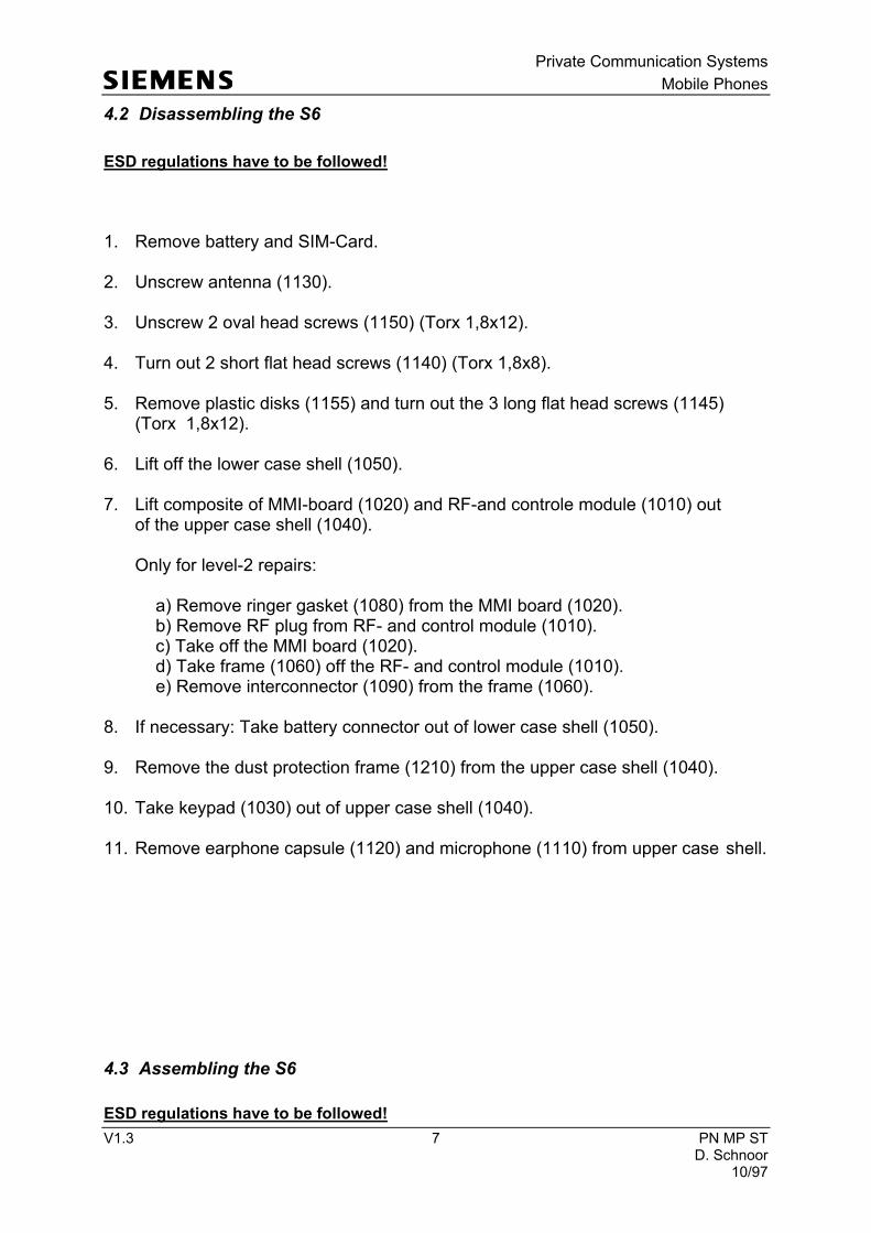
4.2 Disassembling the S6
ESD regulations have to be followed! 1. Remove battery and SIM-Card. 2. Unscrew antenna (1130). 3. Unscrew 2 oval head screws (1150) (Torx 1,8x12). 4. Turn out 2 short flat head screws (1140) (Torx 1,8x8).
5. Remove plastic disks (1155) and turn out the 3 long flat head screws (1145)
(Torx 1,8x12).
6. Lift off the lower case shell (1050).
7. Lift composite of MMI-board (1020) and RF-and controle module (1010) out of the upper case shell (1040). Only for level-2 repairs: a) Remove ringer gasket (1080) from the MMI board (1020). b) Remove RF plug from RF- and control module (1010). c) Take off the MMI board (1020). d) Take frame (1060) off the RF- and control module (1010).
e) Remove interconnector (1090) from the frame (1060).
8. If necessary: Take battery connector out of lower case shell (1050).
9. Remove the dust protection frame (1210) from the upper case shell (1040).
10. Take keypad (1030) out of upper case shell (1040).
11. Remove earphone capsule (1120) and microphone (1110) from upper case shell.
4.3 Assembling the S6
ESD regulations have to be followed!
Private Communication Systems
Mobile Phones
V1.3 8 PN MP ST D. Schnoor 10/97
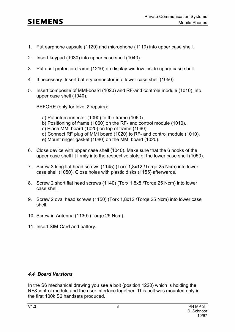
1. Put earphone capsule (1120) and microphone (1110) into upper case shell.
2. Insert keypad (1030) into upper case shell (1040).
3. Put dust protection frame (1210) on display window inside upper case shell.
4. If necessary: Insert battery connector into lower case shell (1050).
5. Insert composite of MMI-board (1020) and RF-and controle module (1010) into
upper case shell (1040). BEFORE (only for level 2 repairs): a) Put interconnector (1090) to the frame (1060). b) Positioning of frame (1060) on the RF- and control module (1010). c) Place MMI board (1020) on top of frame (1060). d) Connect RF plug of MMI board (1020) to RF- and control module (1010). e) Mount ringer gasket (1080) on the MMI board (1020).
6. Close device with upper case shell (1040). Make sure that the 6 hooks of the upper case shell fit firmly into the respective slots of the lower case shell (1050).
7. Screw 3 long flat head screws (1145) (Torx 1,8x12 /Torqe 25 Ncm) into lower case shell (1050). Close holes with plastic disks (1155) afterwards.
8. Screw 2 short flat head screws (1140) (Torx 1,8x8 /Torqe 25 Ncm) into lower case shell.
9. Screw 2 oval head screws (1150) (Torx 1,8x12 /Torqe 25 Ncm) into lower case
shell.
10. Screw in Antenna (1130) (Torqe 25 Ncm).
11. Insert SIM-Card and battery.
4.4 Board Versions
In the S6 mechanical drawing you see a bolt (position 1220) which is holding the RF&control module and the user interface together. This bolt was mounted only in the first 100k S6 handsets produced.
Private Communication Systems
Mobile Phones
V1.3 9 PN MP ST D. Schnoor 10/97
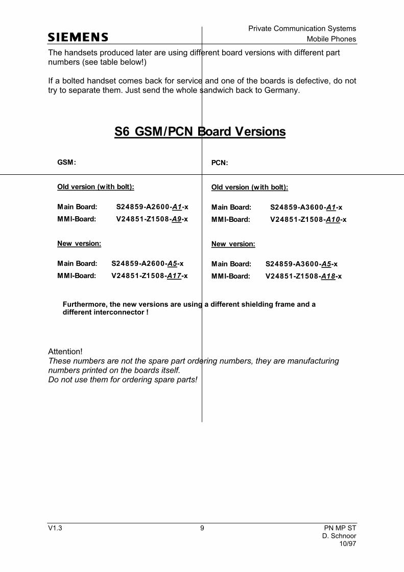
The handsets produced later are using different board versions with different part numbers (see table below!) If a bolted handset comes back for service and one of the boards is defective, do not try to separate them. Just send the whole sandwich back to Germany.
Attention! These numbers are not the spare part ordering numbers, they are manufacturing numbers printed on the boards itself. Do not use them for ordering spare parts!
S6 GSM/PCN Board Versions
GSM:
Old version (with bolt):
Main Board: S24859-A2600-A1-x
MMI-Board: V24851-Z1508-A9-x
New version:
Main Board: S24859-A2600-A5-x
MMI-Board: V24851-Z1508-A17-x
PCN:
Old version (with bolt):
Main Board: S24859-A3600-A1-x
MMI-Board: V24851-Z1508-A10-x
New version:
Main Board: S24859-A3600-A5-x
MMI-Board: V24851-Z1508-A18-x
Furthermore, the new versions are using a different shielding frame and adifferent interconnector !

Private Communication Systems
Mobile Phones
V1.3 10 PN MP ST D. Schnoor 10/97
4.5 Upper Case Protection
If the bolted boards are used, it has to be made sure that one guiding pin in the upper case shell is removed (see drawing!). If the pin is not removed, the case may break! Attention! Do not remove the pin if the unbolted boards are used! The removal of the pin is simply done by cutting it off with a sharp knife or cutter.
4.6 Handset Datecodes
Siemens is using the industrial standard DIN EN 60062 to indicate the production / service dates. The code is printed on the IMEI sticker located under the simcard reader.
guiding
pin

Private Communication Systems
Mobile Phones
V1.3 11 PN MP ST D. Schnoor 10/97
The first character of
the datecode indicates the year of production: F = 1995 H = 1996 J = 1997 The second character indicates the month of production: 1-9 = january to september O = october N = november D= december Example: HD means that the set was produced in december of 1996.
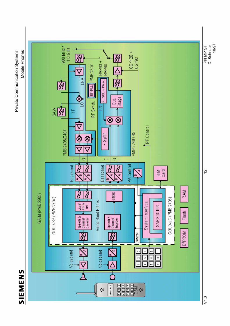
5 Hardware Concept
5.1 Block Diagram
-> YY = Datecode
Private Communication Systems
Mobile Phones
V1.3
12
PN MP ST
D. Schnoor
10/97

Private Communication Systems
Mobile Phones
V1.3 13 PN MP ST D. Schnoor 10/97
5.2 Hardware Description
The handset consists of five major integrated circuits: 1) GOLD-µC (PMB 2706) This microprocessor is responsible for controlling the keyboard, SIM-Card, EEPROM, Flash and RAM. Furthermore it interfaces the GOLD-SP (PMB 2707), controls the power up/power down of the RF module and sets the amplification of the PA. 2) GOLD-SP (PMB 2707) This signal processor is responsible for processing the Rx I/Q signals (filtering, equalizing, speech and channel decoding). Furthermore it does the speech and channel encoding and the GSMK modulation of the Tx I/Q signals. 3) GAIM (PMB 2905) The GAIM provides the interface between the analogue signals (I/Q, voiceband, PA-control) and its digital representation. 4) Receiver Circuit (PMB 2405/07) This circuit provides the following main functionalities: a) Low Noise Amplifier (LNA) with a fixed amplification of +20dB to amplify the input RF signal. b) Mixer to mix down the RF signal to the Intermediate Frequency (IF) c) Programmable IF amplifier with a dynamic range of 60dB ( -10dB ... +50dB in steps of 2dB) d) Mixer to mix down the IF signal to the baseband, generating and inphase (I) and a quadrature (Q) signal. e) Offset compensation for the I/Q signals. 5) Transmitter Circuit PMB 2240/45 This circuit provides the IF synthesizer, the I/Q modulator, prescalers to regulate the RF synthesizer and a buffer stage to feed the PA.
Private Communication Systems
Mobile Phones
V1.3 14 PN MP ST D. Schnoor 10/97
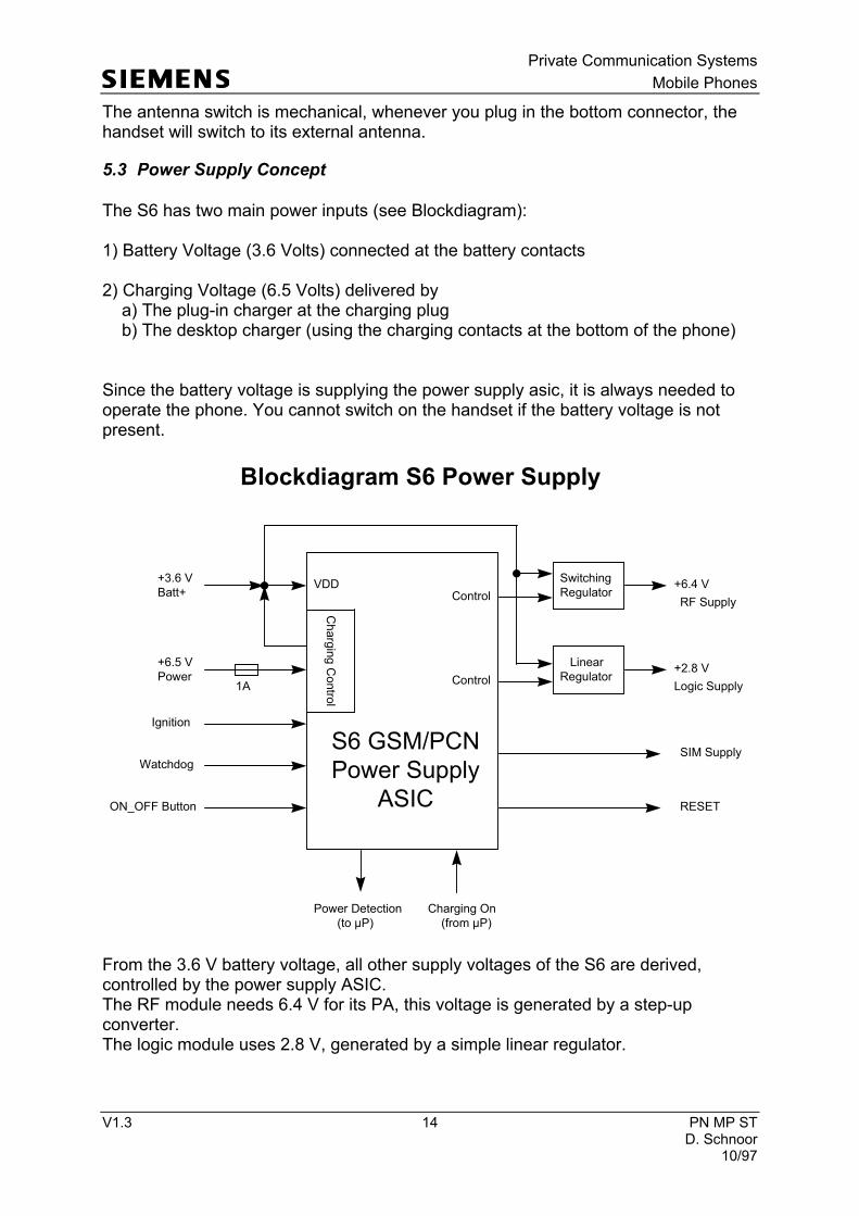
The antenna switch is mechanical, whenever you plug in the bottom connector, the handset will switch to its external antenna.
5.3 Power Supply Concept
The S6 has two main power inputs (see Blockdiagram): 1) Battery Voltage (3.6 Volts) connected at the battery contacts 2) Charging Voltage (6.5 Volts) delivered by a) The plug-in charger at the charging plug b) The desktop charger (using the charging contacts at the bottom of the phone) Since the battery voltage is supplying the power supply asic, it is always needed to operate the phone. You cannot switch on the handset if the battery voltage is not present.
From the 3.6 V battery voltage, all other supply voltages of the S6 are derived, controlled by the power supply ASIC. The RF module needs 6.4 V for its PA, this voltage is generated by a step-up converter. The logic module uses 2.8 V, generated by a simple linear regulator.
ON_OFF Button
S6 GSM/PCN
Power Supply
ASIC
+3.6 V
Batt+
+6.5 V
Power
VDD
Ignition
Watchdog
Charging Contro
l
Power Detection
(to µP)
Charging On
(from µP)
Switching
Regulator
Linear
Regulator
+6.4 V
+2.8 V
Logic Supply
RF SupplyControl
Control
Blockdiagram S6 Power Supply
SIM Supply
RESET
1A
Private Communication Systems
Mobile Phones
V1.3 15 PN MP ST D. Schnoor 10/97
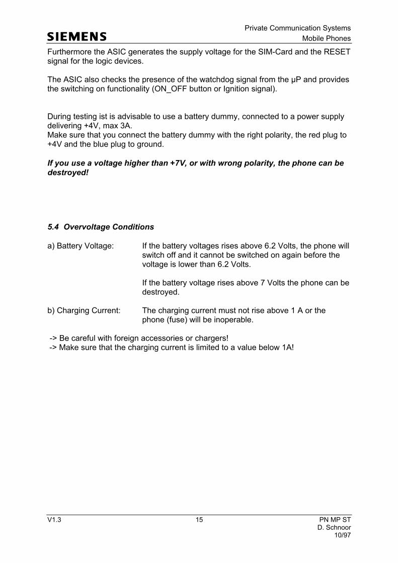
Furthermore the ASIC generates the supply voltage for the SIM-Card and the RESET signal for the logic devices. The ASIC also checks the presence of the watchdog signal from the µP and provides the switching on functionality (ON_OFF button or Ignition signal). During testing ist is advisable to use a battery dummy, connected to a power supply delivering +4V, max 3A. Make sure that you connect the battery dummy with the right polarity, the red plug to +4V and the blue plug to ground.
If you use a voltage higher than +7V, or with wrong polarity, the phone can be
destroyed!
5.4 Overvoltage Conditions
a) Battery Voltage: If the battery voltages rises above 6.2 Volts, the phone will switch off and it cannot be switched on again before the voltage is lower than 6.2 Volts. If the battery voltage rises above 7 Volts the phone can be destroyed. b) Charging Current: The charging current must not rise above 1 A or the phone (fuse) will be inoperable. -> Be careful with foreign accessories or chargers! -> Make sure that the charging current is limited to a value below 1A!

Private Communication Systems
Mobile Phones
V1.3 16 PN MP ST D. Schnoor 10/97
6 S6 GSM / PCN Software Options
The following list will help you to understand what the different software options are for and how they are used. Keep in mind that many of these features are network dependent, a malfunction cannot automatically be blamed on the handset.
OPTIONS
1 RINGER
1.1 Ringer On / Off The ringer can be switched on or off
1.2 Volume Adjust The ringer volume can be adjusted
1.3 Tone Adjust The ringer tone can be adjusted
2 DIVERT
2.1 If not Reachable Clear / Set / Check Divert when the phone is switched off
2.2 If no Reply Clear / Set / Check Divert if nobody answers the call
2.3 All Calls Clear / Set / Check Divert all incoming calls
2.4 If Busy Clear / Set / Check Divert if the line is busy
3 CONTROL USE
3.1 Key Lock Lock your keys from unwanted pressing. Unlock by holding down the „#“ button.
3.2 Pin Control Alter / On / Off Some networks allow you to swith off your PIN control
3.3 Allow only *���� Set / Clear PIN2
This will limit all outgoing calls to the numbers stored in the
FDN - Phonebook (FDN = Fixed Dialling Numbers), which is only available in a phase 2 SIM-Card.
Private Communication Systems
Mobile Phones
V1.3 17 PN MP ST D. Schnoor 10/97
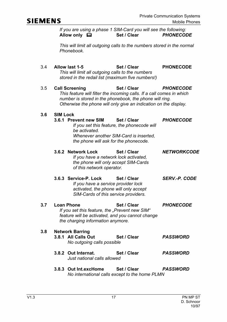
If you are using a phase 1 SIM-Card you will see the following:
Allow only ���� Set / Clear PHONECODE This will limit all outgoing calls to the numbers stored in the normal Phonebook.
3.4 Allow last 1-5 Set / Clear PHONECODE This will limit all outgoing calls to the numbers stored in the redail list (maximum five numbers!)
3.5 Call Screening Set / Clear PHONECODE This feature will filter the incoming calls. If a call comes in which number is stored in the phonebook, the phone will ring. Otherwise the phone will only give an indication on the display.
3.6 SIM Lock
3.6.1 Prevent new SIM Set / Clear PHONECODE If you set this feature, the phonecode will be activated. Whenever another SIM-Card is inserted, the phone will ask for the phonecode.
3.6.2 Network Lock Set / Clear NETWORKCODE If you have a network lock activated, the phone will only accept SIM-Cards of this network operator.
3.6.3 Service-P. Lock Set / Clear SERV.-P. CODE If you have a service provider lock activated, the phone will only accept SIM-Cards of this service providers.
3.7 Loan Phone Set / Clear PHONECODE If you set this feature, the „Prevent new SIM“ feature will be activated, and you cannot change the charging information anymore.
3.8 Network Barring
3.8.1 All Calls Out Set / Clear PASSWORD No outgoing calls possible
3.8.2 Out Internat. Set / Clear PASSWORD Just national calls allowed
3.8.3 Out Int.excHome Set / Clear PASSWORD No international calls except to the home PLMN
Private Communication Systems
Mobile Phones
V1.3 18 PN MP ST D. Schnoor 10/97
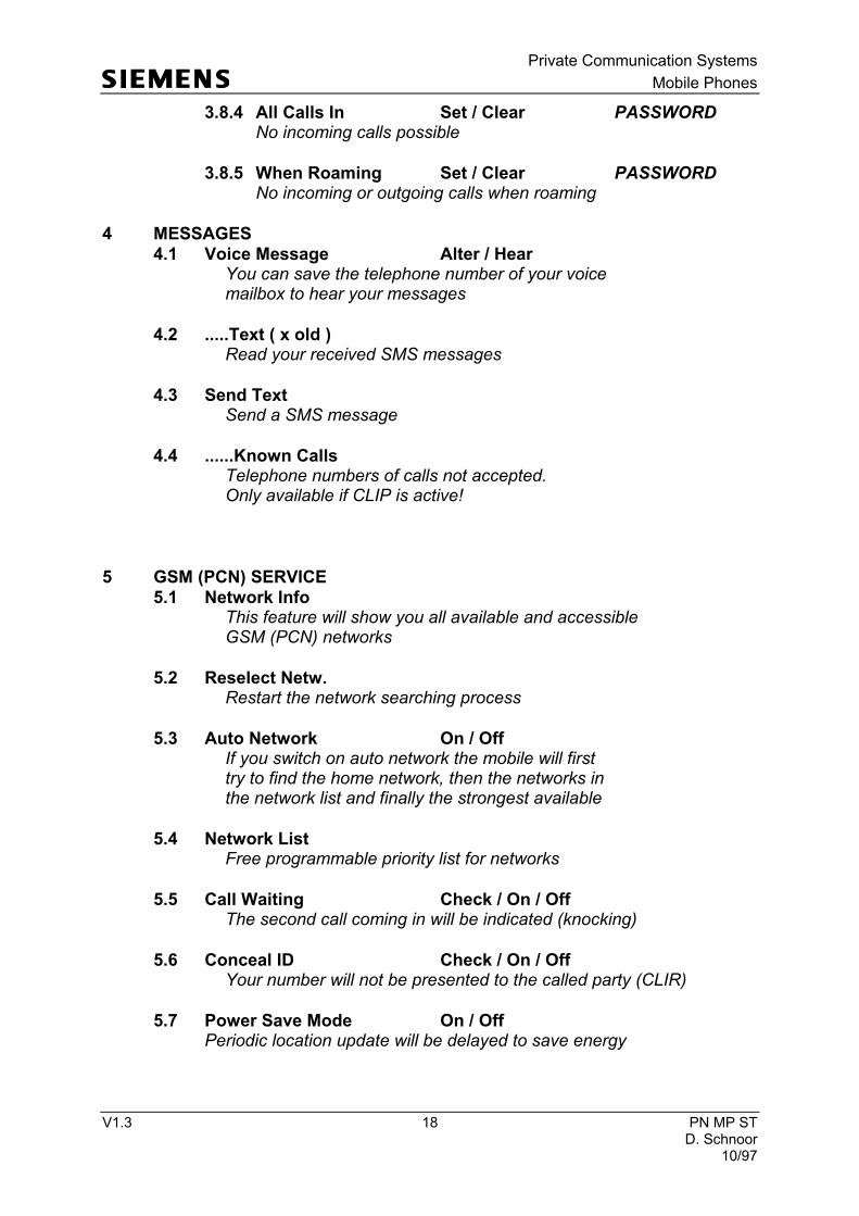
3.8.4 All Calls In Set / Clear PASSWORD No incoming calls possible
3.8.5 When Roaming Set / Clear PASSWORD No incoming or outgoing calls when roaming
4 MESSAGES
4.1 Voice Message Alter / Hear You can save the telephone number of your voice mailbox to hear your messages
4.2 .....Text ( x old ) Read your received SMS messages
4.3 Send Text Send a SMS message
4.4 ......Known Calls Telephone numbers of calls not accepted. Only available if CLIP is active!
5 GSM (PCN) SERVICE
5.1 Network Info This feature will show you all available and accessible GSM (PCN) networks
5.2 Reselect Netw. Restart the network searching process
5.3 Auto Network On / Off If you switch on auto network the mobile will first try to find the home network, then the networks in the network list and finally the strongest available
5.4 Network List Free programmable priority list for networks
5.5 Call Waiting Check / On / Off The second call coming in will be indicated (knocking)
5.6 Conceal ID Check / On / Off Your number will not be presented to the called party (CLIR)
5.7 Power Save Mode On / Off Periodic location update will be delayed to save energy

Private Communication Systems
Mobile Phones
V1.3 19 PN MP ST D. Schnoor 10/97
6 TIME CHARGE
6.1 Last Call Length and cost of last call
6.2 Total Calls Clear (PHONECODE) Lenght and cost of all calls
6.3 Auto Display On / Off Automatic lenght and cost display
6.4 1 Minute Beep On / Off 1 minute indication during call
6.5 Charge Rate Setting of charge rate
6.6 Charge Limit On / Off (PHONECODE / PIN 2) Setting and activating of charge limit If you have a phase 1 SIM-Card you will have to enter the phonecode, with a phase 2 SIM-Card the PIN 2 is needed.
7 LANGUAGE
7.1 Automatic Language which preferred in the SIM-Card is used, if the language is in the mobile software.
7.2 English
7.3 Deutsch
7.4 Francais
8 CAR USE
8.1 Auto Answer On / Off If a call comes in it will be automatically answered
8.2 Auto Power Off You can set the time of auto power off after ignition has been switched of.
9 SET UP
9.1 DTMF Key Tone On / Off DTMF for remote control of answering machines etc.
9.2 Key Sound Click / Tone / Silent

Private Communication Systems
Mobile Phones
V1.3 20 PN MP ST D. Schnoor 10/97
9.3 Any Key Answer On / Off Any key will hook off
9.4 Illumination On / Off Switch off illumination permanently to save energy
9.5 Own Greeting On / Off Program your own greetings text
9.6 Service Tones On / Off Service tones are audible when loggin into the net- work or connecting a call etc.
9.7 Master Reset This feature will reset factory settings, but not the se- curity codes or charge limits etc.
9.8 Phone Status This shows your IMEI-Number and the Software-Date (Press left softkey once!)
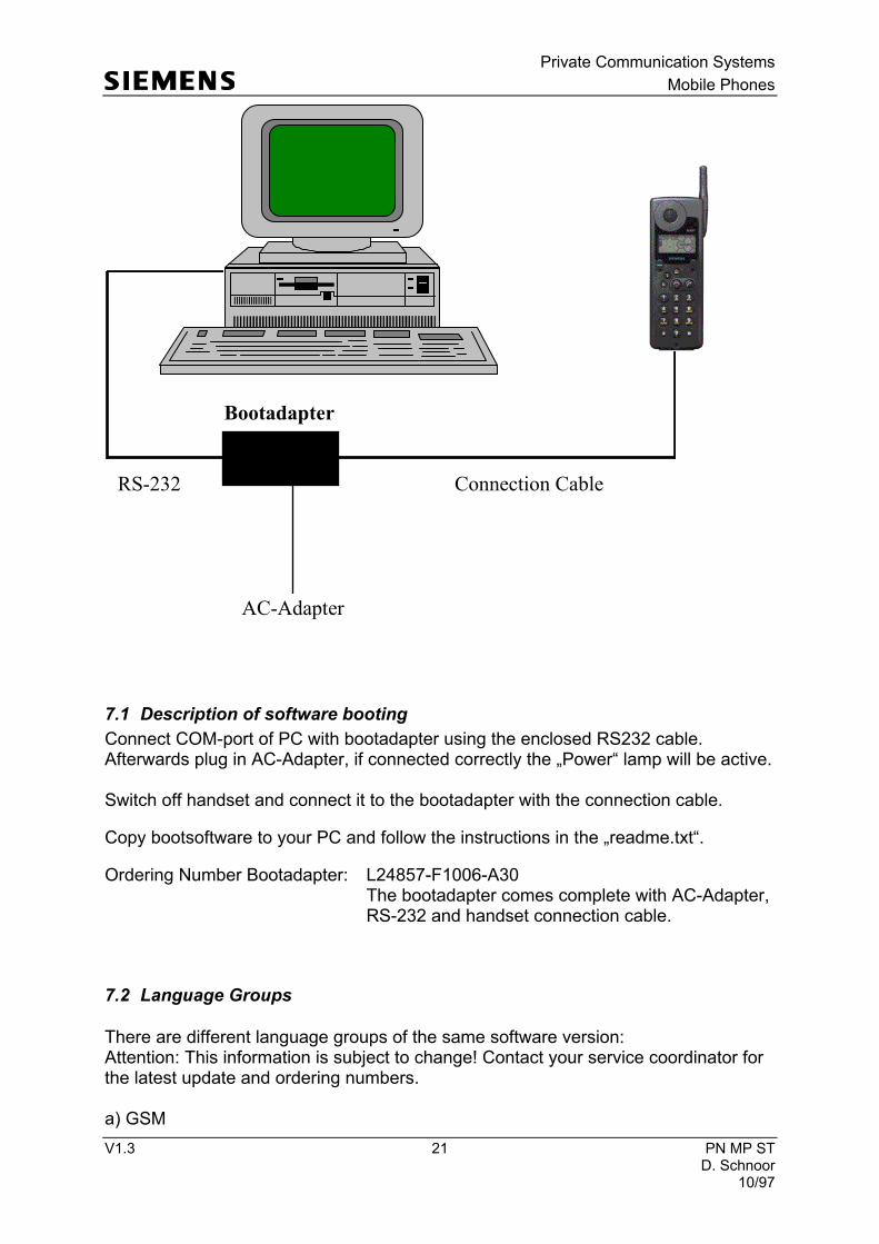
7 Software programming
The software of the S6 GSM / PCN handsets is programmed directly from a PC using the bootadapter (see drawing below).
Private Communication Systems
Mobile Phones
V1.3 21 PN MP ST D. Schnoor 10/97
7.1 Description of software booting
Connect COM-port of PC with bootadapter using the enclosed RS232 cable. Afterwards plug in AC-Adapter, if connected correctly the „Power“ lamp will be active. Switch off handset and connect it to the bootadapter with the connection cable.
Copy bootsoftware to your PC and follow the instructions in the „readme.txt“.
Ordering Number Bootadapter: L24857-F1006-A30 The bootadapter comes complete with AC-Adapter, RS-232 and handset connection cable.
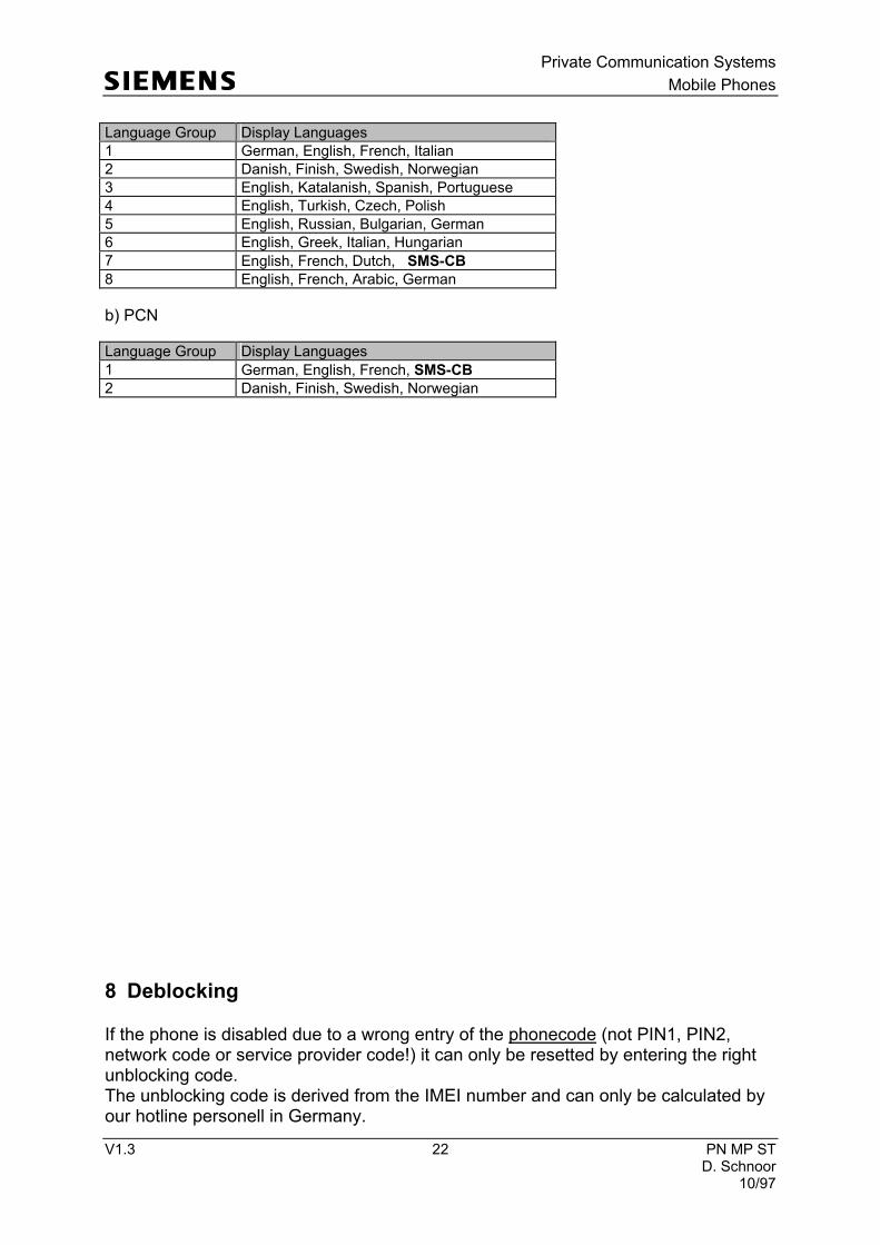
7.2 Language Groups
There are different language groups of the same software version: Attention: This information is subject to change! Contact your service coordinator for the latest update and ordering numbers. a) GSM
AC-Adapter
RS-232
Bootadapter
Connection Cable
Private Communication Systems
Mobile Phones
V1.3 22 PN MP ST D. Schnoor 10/97
Language Group Display Languages
1 German, English, French, Italian
2 Danish, Finish, Swedish, Norwegian
3 English, Katalanish, Spanish, Portuguese
4 English, Turkish, Czech, Polish
5 English, Russian, Bulgarian, German
6 English, Greek, Italian, Hungarian
7 English, French, Dutch, SMS-CB
8 English, French, Arabic, German
b) PCN
Language Group Display Languages
1 German, English, French, SMS-CB
2 Danish, Finish, Swedish, Norwegian
8 Deblocking
If the phone is disabled due to a wrong entry of the phonecode (not PIN1, PIN2, network code or service provider code!) it can only be resetted by entering the right unblocking code. The unblocking code is derived from the IMEI number and can only be calculated by our hotline personell in Germany.
Private Communication Systems
Mobile Phones
V1.3 23 PN MP ST D. Schnoor 10/97
If you need unblocking codes just send a fax with the IMEI numbers to: Siemens AG PN KE SH World Service Center Bocholt, Germany Fax: +49 2871 91 3007
Please use the appropriate form provided by your service coordinator!
9 Battery
9.1 Specification

Private Communication Systems
Mobile Phones
V1.3 24 PN MP ST D. Schnoor 10/97
The S6 battery is a Lithium-Ion type with a voltage of 3.6 Volts and a capacity of 1000 mAh.
The connections BATT+ and GND are used to supply the mobile, while RCODE is used to detect the battery technology. BATT_TEMP is used to measure the battery temperature.
9.2 Short Circuit Protection
The battery is short-circuit protected by an electronic fuse. The resetting of the fuse can be done by the following procedures: * Plug the battery into the desktop charger. or

Private Communication Systems
Mobile Phones
V1.3 25 PN MP ST D. Schnoor 10/97
* Apply +5 Volts between the BATT+ and GND contacts (see drawing!) Limit the current to 10mA.
9.3 Deep Discharge
If the battery is deeply discharged it can be recharged by the following procedure: Insert flat battery into handset and connect travel charger. The charging symbol will not be visible. Wait for appr. 1 hour and disconnect charger afterwards. Remove battery and reinsert it. If you connect the travel charger now, the charging symbol must be visible on the handset display.
9.4 Battery Datecodes
The datecode printed on the battery will give you the following information:
Example: TOS 8 G9 VA 1 TOS = Cells supplied by Toshiba 8 = Revision level
G9 = Datecode VA = Varta (battery manufacturer) 1 = Place of manufacturing (1=Germany ,2= Novibor, Czech Republic) Datecode: 1. Character: Year of production (F= 1995, G= 1996) 2. Character: Month of production (1-9 means January to September; O=October; N=November ; D=December) From february of 1997 on, Varta is going to adapt its datecoding according to industrial standard DIN EN 60062. This means that the character indicating the year 1997 will be a „J“
Example: TOS 8 J2 VA 1 This battery was produced in february of 1997!
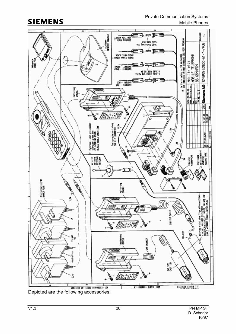
10 S6 GSM / PCN Accessories
Private Communication Systems
Mobile Phones
V1.3 26 PN MP ST D. Schnoor 10/97
Depicted are the following accessories:
Private Communication Systems
Mobile Phones
V1.3 27 PN MP ST D. Schnoor 10/97
10.1 Desktop Charger
This charger can be used to charge the battery alone or the battery inserted into the handset, but not both at the same time! Furthermore ist is helpful to reset disabled batteries. The desktop charger is supplied by the AC-adapter coming with the handset.
10.2 Car Charger
The car charger is connected to the cigarette lighter of the car with a flexible cable. This accessory will charge the handset battery, it can not be used as a car kit because it does not have a RF connection to the external antenna.
Note: The cigarette lighter plug is only usable for 12V car batteries. Do not connect it to a 24V truck battery! Never cut off the cigarette lighter plug and never make a direct connection to the car battery. There is a voltage regulator in the plug which is regulating the 12V down to the charging voltage of the handset!
10.3 Car Kit Basic
The car kit basic is connected to the cigarette lighter of the car with a flexible cable. This accessory will charge the handset battery, and it can also be used as a car kit because it does provide a RF connection to the external antenna. You have to use a external antenna because the phone automatically switches off the internal antenna!
Note: The cigarette lighter plug is only usable for 12V car batteries and for 24V truck batteries! Never cut off the cigarette lighter plug and never make a direct connection to the car battery. There is a voltage regulator in the plug which is regulating the 12V/24V down to the charging voltage of the handset!
10.4 Car Kit Handsfree

Private Communication Systems
Mobile Phones
V1.3 28 PN MP ST D. Schnoor 10/97
This car kit provides the full range of functionalities: handsfree microphone and loudspeaker, battery charging and radio mute. The connections to the battery are made directly using the cables with fuses for „battery+“, „battery-“ and „ignition“. Furthermore it provides a „radio mute“ connection to the car radio. See drawing „S6 GSM / PCN Accessories“ for details-
11 Spare Parts List
List of spare parts / jigs and tools / swap units

Private Communication Systems
Mobile Phones
V1.3 29 PN MP ST D. Schnoor 10/97
Attention: The following lists are subject to change. Contact your service coordinator for the latest update!
11.1 swap units
These are complete telephones for swap-purposes.
Part-Number Part Q.p.P.
L24859-C2600-A910 S6/GSM/SWAP/LG 1 /1
L24859-C2600-A914 S6/GSM/SWAP/TIM/LG 1 /1
L24859-C2600-A915 S6/GSM/SWAP/OPI/LG 1 /1
L24859-C2600-A917 S6/GSM/SWAP/TDM/SIM-LOCK /1
L24859-C2600-A922 S6/GSM/SWAP/MOVISTAR/SIM-LOCK /1
L24859-C2600-A923 S6/GSM/SWAP/AIRTEL/SIM-LOCK /1
L24859-C2600-A924 S6/GSM/SWAP/SIEMENS/LG 7 /1
L24859-C3600-A910 S6/PCN/SWAP/LG 1 /1
L24859-C3600-A914 S6/PCN/SIM-LOCK/ADAM/SWAP/LG 1 /1
L24859-C3600-A915 S6/PCN/SIM-LOCK/MUTIA/SWAP/LG 2 /1
LG = Language Group
11.2 spare parts
Part.-No. Parts Q.p.P.
L24859-A2600-A905 S6/GSM/RF/CONTROL/BOARD/ LG1 /1
L24859-A3600-A905 S6/PCN/RF/CONTROL/BOARD/LG1 /1
L24851-F1000-A20 CONNECTION-BOX/+LOUDSPEAKER /1
L36158-A4-B2 LOWER/CASE/SHELL/STD/COMPLETE /20

Private Communication Systems
Mobile Phones
V1.3 30 PN MP ST D. Schnoor 10/97
L36158-A4-C8 FOAM/SEAL/BUZZER /10
L36158-A4-C11 COVER/RUBBER/SCREW /25
L36158-A4-C27 SCREEN/FRAME /10
L36212-Z3-C15 ACOUSTIC/EARPHONE /10
L36254-Z6-C59 MICROPHONE/GSM/PCN /10
L36334-Z93-C253 INTERCONNECTOR /10
L36851-Z1361-B18 BATTERY CONTACT 4pins /40
L36851-Z1402-A10 KEYPAD/GSM/PCN /10
L36851-Z1508-A17 S6/GSM/USER INTERFACE /1
L36851-Z1508-A18 S6/PCN/USER INTERFACE /1
11.3 customer spezified spare parts
L36158-A4-B1 UPPER/CASE/SHELL/GSM/STD /20
L36158-A4-B11 UPPER/CASE/SHELL/PCN/STD /20
L36158-A4-B22 UPPER/CASE/SHELL/GSM/TDM /20
L36158-A4-B28 UPPER/CASE/SHELL/GSM/TIM /20
L36158-A4-B29 UPPER/CASE/SHELL/GSM/OPI /20
L36158-A4-B31 UPPER/CASE/SHELL/GSM/MOVISTAR /20
L36158-A4-B32 UPPER/CASE/SHELL/GSM/AIRTEL /20
11.4 Accessories and wearing parts
Part.-No. Parts Q.p.P.
L24158-Z27-A308 SCREW/FLAT/HEAD/TORX 1,8x8 /40
L24851-Z2705-A20 BATTERY/PACK/LITHIUM-ION /1
L36146-A1016-D CON.CABLE/BATTERY /1
L36158-A4-C40 BELT CLIP /10
L36158-A5-B1 HOLDER/HANDSET /1
L36158-Z27-A212 SCREW/FLAT/HEAD/TORX 1,8x12 /40

Private Communication Systems
Mobile Phones
V1.3 31 PN MP ST D. Schnoor 10/97
L36158-Z28-A312 SCREW/OVAL/HEAD/TORX1,8x12/HANDSET/ *) /40
L36254-Z6-C61 HANDSFREE/MICROPHON/GSM/PCN /1
L36851-Z1303-A134 CON.CABLE/CARKIT/HF /1
L36158-A2-C5 DISTANCE/STRIP *) /1
L36158-A5-C4 PLUG-IN/CONSOLE *) /1
L36158-A5-C5 PLUG-IN/COVER *) /1
L24851-Z2630-A2 DESK-TOP/CHARGER #) /4
L36851-Z2618-V1 PLUG-IN/POWER-SUPPLY/EU /1
L36851-Z2618-V2 PLUG-IN/POWER-SUPPLY/UK /1
L36851-Z2618-V3 PLUG-IN/POWER-SUPPLY/AUS /1
L36851-Z2618-V4 PLUG-IN/POWER-SUPPLY/TAIWAN /1
#) Plug-In power supply not included *) only for handsfree carki
11.5 Documentation
L36859-N2600-A100-*-4-E19 S6/USER GUIDE/UG1 GBR/DEU/FRA/ITA /1
L36859-N2600-A101-*-5-W19 S6/USER GUIDE/UG2 DK/FIN/SWE/NOR /1
L36859-N2600-A102-*-9-K19 S6/USER GUIDE/UG3 GBR/KATAL/ESP/POR /1
L36859-N2600-A103-*-9-L19 S6/USER GUIDE/UG4 GBR/TUR/TCH/POL /1
L36859-N2600-A104-*-9-M19 S6/USER GUIDE/UG5 GBR/FRA/RUS/BUL /1
L36859-N2600-A105-*-9-N19 S6/USER GUIDE/UG6 GBR/GRI/ITA/HUN /1
L36859-N2600-A106-*-3-Q19 S6/USER GUIDE/UG7 GBR/FRA/NDL /1
L36859-N2600-A107-*-3-T19 S6/USER GUIDE/UG8 GBR/FRA/ARABIC /1
L36859-N2600-A108-*-6-C19 S6/USER GUIDE/UG9 GBR/CHN /1
L36859-N2600-A109-*-6-319 S6/USER GUIDE/UG10 GBR/DEU/FRA /1
L36859-N2600-A110-*-7-219 S6/USER GUIDE/UG11 ITL /1
L36859-N2600-A111-*-6-319 S6/USER GUIDE/UG12 GBR/DEU/FRA /1
L36859-N2600-A112-*-9-K19 S6/USER GUIDE/UG13 GBR/KATAL/ESP/PRT /1
L36859-N2600-A113-*-9-K19 S6/USER GUIDE/UG14 GBR/KATAL/ESP/PRT /1
L36859-N2600-A114-*-5-419 S6/USER GUIDE/UG15 NDL /1
L36859-N3600-A100-*-6-319 S6/PCN/USER GUIDE/UG1 DEU/GBR/FRA /1