service manual nº 11 gemini interlock … manual nº 11 series 10/19/99 ... gem-312il & -300il...
TRANSCRIPT

Gemini 300IL
SERVICE MANUAL Nº 11Series 10/19/99
Gemini 312IL
F-1901.:65 14.4 P1 REV.A
FFFFFINDINDINDINDIND OUTOUTOUTOUTOUT MOREMOREMOREMOREMOREONONONONON THETHETHETHETHE WEBWEBWEBWEBWEB.....W I L B U RW I L B U RW I L B U RW I L B U RW I L B U R C U RC U RC U RC U RC U R T I S . C O MT I S . C O MT I S . C O MT I S . C O MT I S . C O M
FOR THE LATEST SPECIFICATIONS AND INFORMATION GO TOWWW.WILBURCURTIS.COMISO 9001 REGISTERED
C
WILBUR CURTIS COMPANYMontebello, CA 90640
GEMINI INTERLOCK COFFEEBREWING SYSTEMS
GEM-312IL & -300IL Satellite Brewer InstructionsWWWWWILBURILBURILBURILBURILBUR C C C C CURTISURTISURTISURTISURTIS C C C C COMPOMPOMPOMPOMPANYANYANYANYANY, I, I, I, I, INCNCNCNCNC.....

SHIPPING CARTON CONTENTS
Brewer(Dash Numbers Indicate Variations)Brew Cone with HandleWire BasketAdjustable Legs, 4"Satellite Server with Lid3/8 Male X 3/8 Compression Elbow"S" Faucet, Self ClosingPaper FiltersSatellite Faucet Guard
ITEMQTY1114111
351
Part NºGEM-3OOILWC-3311WC-3301WC-3500GEM-3WC-2805WC-1800GEM-6WC-6417
GEMINI 300IL
GEMINI 312IL
ITEMQTY1224212
702
Part NºGEM 312ILWC-3311WC-3301WC-3500GEM-3WC-2805WC-1800GEM-6WC-6417
The shipping carton contains the following standard items:
Brewer (Dash Numbers Indicate Variations)Brew Cone with HandleWire BasketAdjustable Legs, 4"Satellite Server with Lid (Less Faucet)3/8 Male X 3/8 Compression Elbow"S" Faucet, Self ClosingPaper FiltersSatellite Faucet Guard

1
1
1
2
2
3
3
4
5
5
5
6
6
6
6
7
7-11
1 1
12-15
15-16
17-18
20-21
2 1
2 2
2 3
Back Cover
Installation Instructions - Electrical Data . . . . . . . . . . . .
Electrical Data GEMINI 312IL . . . . . . . . . . . . . . . . .
Electrical Data GEMINI 300IL. . . . . . . . . . . . . . . . . .
Plumbing Information . . . . . . . . . . . . . . . . . . . .
Set-up Instructions . . . . . . . . . . . . . . . . . . . . .
Grinder Hook-up . . . . . . . . . . . . . . . . . . . . . .
Programming . . . . . . . . . . . . . . . . . . . . . . . .
Operating the Interlock System . . . . . . . . . . . . . . . .
By-pass Operation . . . . . . . . . . . . . . . . . . . . . .
By-pass Adjustment . . . . . . . . . . . . . . . . . . . . .
Hot Water Dispensing . . . . . . . . . . . . . . . . . . . .
Coffee Requirements - Type & Quantity . . . . . . . . . . . .
Satellite Holding Temperature . . . . . . . . . . . . . . . .
Care & Maintenance . . . . . . . . . . . . . . . . . . . .
Cleaning . . . . . . . . . . . . . . . . . . . . . . . . . .
High Temperature Reset Thermostat . . . . . . . . . . . . . .
Troubleshooting . . . . . . . . . . . . . . . . . . . . .
Function of Gemini . . . . . . . . . . . . . . . . . . . . .
Gemini 312IL Illustrated Parts List . . . . . . . . . . . . .
Gemini 300IL Illustrated Parts List . . . . . . . . . . . . .
Gemini Satellite & Warmer, Illustrated Parts List . . . . . . .
Gemini Satellite Parts List . . . . . . . . . . . . . . . . .
Wiring Diagram - GEM 5 & 8 . . . . . . . . . . . . . . . . .
Wiring Diagram - Gemini 312IL Single Phase . . . . . . . . . .
Wiring Diagram - Gemini 300IL Single Phase . . . . . . . . . .
Warranty . . . . . . . . . . . . . . . . . . . . . .
IndexPAGESUBJECT
-

INSTALLATION INSTRUCTIONS Electrical Data for GEM-312IL
Single Phase, 3 Wire + Ground
Three Phase, 3 Wire + Ground (All Components 220V) and Three Phase, 4 wire + Ground. (All Components 120V Except Heating Elements in Tank)
Single Phase, 2 Wire + Ground (All Components 220V)
Electrical Data for GEM-300IL (Not Available in Three Phase) Single Phase, 3 Wire + Ground
Single Phase, 2 Wire + Ground (All Components 220V)
POWER SUPPLY CONNECTIONS Single Phase, 3 Wires* Plus Ground Three Phase, 3 Wires* Plus Ground
Note: Read Serial Plate for Power Requirements
WARNING To prevent shock, the body of the brewer must be securely grounded. AGREEN grounding screw, located inside the electrical box is provided for this purpose.
L1
L2
L3
GND
Red
BlackStriped
BREWERWIRES
POWER SUPPLYWIRES
Blue220V
220V
220V
* Do not use less than #10 AWG * Do not use less than #12 AWG
Page 1
Voltage Required:Power Consumption:
Circuit Breaker Capacity:
208/240V (120V to Neutral)29 Amps at 220V 6300 Watts40 Amps (30 Amp Minimum on 220V, 40 Amp if 208V)
Voltage Required:Power Consumption:
Circuit Breaker Capacity:
208/240 Volts (120V to Neutral in 4 Wire + Ground)16.6 Amps at 220V 6300 Watts20 Amps Minimum.
Voltage Required:Power Consumption:
Circuit Breaker Capacity:
208/240 Volts 29 Amps at 220V 6300 Watts40 Amps. (30 Amp Minimum on 220V, 40 Amp if 208V)
Voltage Required:Power Consumption:
Circuit Breaker Capacity:
208/240V (120V to Neutral)19 Amps at 220V 4175 Watts30 Amps (20 Amps Minimum if 220V)
Voltage Required:Power Consumption:
Circuit Breaker Capacity:
208-240 Volts19 Amps at 220V 4175 Watts30 Amps. (20 Amps Minimum if 220V)
POWER SUPPLYWIRES
BREWERWIRES
L1
L2
Neutral
Ground
120V
208-240VRed
Blue
White
!

Page 2
PLUMBING INFORMATIONA 3/8" pipe thread X 3/8" compression 90º elbow is supplied with this brewer for water line connection.Use 3/8" O.D. copper tubing to connect water to the machine.We recommend using a good water filter in the line before entering the brewer. Some type of waterstrainer MUST be used to obtain a trouble-free operation. The removable top back panel of the brewerhas two 1/4 dia. screws to facilitate mounting the water filter.
CAUTION: DO NOT connect this brewer to hot water. The inlet valve is not rated for hot water.
SET-UP INSTRUCTIONSAfter the brewer has been properly installed to comply with all local electrical and plumbing codes, pro-ceed to start the brewing operation as follows:
1. Remove top cover. Locate and remove lid from the heating tank. Make sure the primarythermostat (part no. WC-517) is turned off. The thermostat is item no. 88 in Gemini312IL parts list and item no. 58 in the Gemini 300IL parts list.
2. Open the water supply valve.
3. Turn main breaker on. Turn toggle switch in back of brewer on. At thistime the water will start flow in into the heating tank. Turn On/Off switch in front panelon. This will energize the controls and the switches will light up.
4. Place clean satellite on warmer deck.
5. Push warmer switch to ON position to preheat the satellite.NOTE: The satellite must be preheated for ten minutes before brewing coffee.Never brew coffee in a cold satellite. The coffee temperature will drop instantly.
6. When the heating elements are covered with water, turn primary thermostat, WC-517, on.
7. When water shuts off, reinstall the tank lid.
Allow 15 minutes for the water to reach 200°F inside the heating tank. After the initial heat up, thetemperature recovery is instantaneous. You may brew continuously.

INSTRUCTIONS FOR CONNECTING TO INTERLOCK GRINDER
1. Open the top cover (loosen four slotted screws).2. The Gemini 312IL brewer has two timers (right and left). The Gemini 300IL brewer has only one
timer. On the timer there is a small function switch marked RUN and PROGRAM. Push the switchto the PROGRAM position. On the Gemini 312IL, you can program the timers one at a time ortogether.
3. Push the ON/OFF switch, on the front panel, to the ON position. The indicator lights, over the brewswitches, will flash on the side that is controlled by the timer(s) that you're working on.
4. Slide an empty brew cone into the brew rails, beneath the sprayhead.5. Place a graduated container under the brew cone to measure the water coming from the sprayhead.6. Choose the brew switch that you want to set and press once. Hot water will start to spray in the brew
cone and into the measuring container. As soon as the amount of water has reached the desired level,press the brew switch again. This stops the brew cycle. This brew switch is now set for the amount ofliquid in the container. Repeat this procedure on the other switches until all of them have been pro-grammed.
7. Return to the timer(s) and switch back to the RUN position. Replace the top cover on the unit.
Page 3
1. Place grinder near brewer.2. With the top cover removed, take out the empty strain relief from hole labeled INTERLOCK in back of
brewer. Pass the end of the grinder interlock cable through this hole. On single head brewers plug the cabledirectly into timer WC-642 or into the interlock cable (if present). On dual head brewers plug the inter-lock cable into the timer interlock cable.
3. Place strain relief onto cable outside of brewer. Connection to timer cable should be inside brewer formaximum durability. Use a plier to squeeze the strain relief to slip it into the hole. Plug linecord intopower outlet.
4. To program the grinder, refer to the manual supplied with the grinder.
123456789012345678901234567890121234567890123456789012345678901212345678901234567890123456789012123412345678901234567890123456789012123456789012345678901234567890121234567890123456789012345678901212341234567890123456789012345678901212345678901234567890123456789012123456789012345678901234567890121234123456789012345678901234567890121234567890123456789012345678901212345678901234567890123456789012123412345678901234567890123456789012123456789012345678901234567890121234567890123456789012345678901212341234567890123456789012345678901212345678901234567890123456789012123456789012345678901234567890121234123456789012345678901234567890121234567890123456789012345678901212345678901234567890123456789012123412345678901234567890123456789012123456789012345678901234567890121234567890123456789012345678901212341234567890123456789012345678901212345678901234567890123456789012123456789012345678901234567890121234123456789012345678901234567890121234567890123456789012345678901212345678901234567890123456789012123412345678901234567890123456789012123456789012345678901234567890121234567890123456789012345678901212341234567890123456789012345678901212345678901234567890123456789012123456789012345678901234567890121234123456789012345678901234567890121234567890123456789012345678901212345678901234567890123456789012123412345678901234567890123456789012123456789012345678901234567890121234567890123456789012345678901212341234567890123456789012345678901212345678901234567890123456789012123456789012345678901234567890121234
CAUTION: As with all electrical equipment, caution must be taken to avoid electricalshock. The following steps will also involve working with hot water. Scalding may occurif care is not taken against spilling.
The amount of coffee brewed is controlled by timers that limit the duration of water flow coming from theheating tank. Both brewers have preset switches marked 12 CUPS, 24 CUPS and 36 CUPS. Typically,you would set up the 12 CUP brew switch to brew around twelve cups, the 24 CUP switch to brew abouttwentyfour cups, etc.. However, the actual quantity of coffee depends on how you program the brewer.
PROGRAM SETTING - GEMINI 312IL & GEMINI 300IL BREWER
IMPORTANT: Following the Set-up Instructions, your brewer is ready to brew coffee. This brewer isset-up at the factory to brew 12, 24 or 36 cups of coffee. This will be fine for most brewing require-ments. If you would like to adjust this setting, continue with the following programming instructions.
!

123456789012345678901234567890121234567890123456789012345678901212345678901234567890121234567890123456789012345678901212345678901234567890123456789012123456789012345678901212345678901234567890123456789012123456789012345678901234567890121234567890123456789012123456789012345678901234567890121234567890123456789012345678901212345678901234567890121234567890123456789012345678901212345678901234567890123456789012123456789012345678901212345678901234567890123456789012123456789012345678901234567890121234567890123456789012123456789012345678901234567890121234567890123456789012345678901212345678901234567890121234567890123456789012345678901212345678901234567890123456789012123456789012345678901212345678901234567890123456789012123456789012345678901234567890121234567890123456789012123456789012345678901234567890121234567890123456789012345678901212345678901234567890121234567890123456789012345678901212345678901234567890123456789012123456789012345678901212345678901234567890123456789012123456789012345678901234567890121234567890123456789012123456789012345678901234567890121234567890123456789012345678901212345678901234567890121234567890123456789012345678901212345678901234567890123456789012123456789012345678901212345678901234567890123456789012123456789012345678901234567890121234567890123456789012
OPERATING THE INTERLOCK SYSTEM
2. When the Grinder Stops, Slide the BrewCone into the Rails on the Brewer. On the312 you may use either side, as both areinterlocked.
3 . Push the Lighted Brew Switch with theLighted Indicator. Coffee Will Start to Brew.
To Interrupt a Brew Cycle, Push the ON/OFFSwitch.
CAUTION: Once the brew cycle has finished be sure the brew cone is com-pletely empty before attempting to lift the satellite server from the brewer.Scalding may occur from hot liquid still in the brew cone. Allow it to drip outa few minutes just to be safe.
NOTE: The brewer and grinder may be operated independently, without Inerlock connection.
Page 4
Make sure that the Set-up Instructions, are complete beforeattempting to operate the Interlock System.
1 . Push the Brew Cone into Place on theGrinder.Decide on Regular or Decaf. Push 12, 24 or36 Cup Switch. Coffee Will Start to Grind.
!

HOT WATER DISPENSING
Page 5
BY-PASS FLOW OPERATIONThese brewers are set at the factory to brew 12, 24 or 36 cups of coffee. The 36 cup brew cycle has a by-pass valvethat will by-pass up to 40% of the water around the coffee grounds. If you desire to change this setting for anyreason, you may do so by adjusting the by-pass valve (part no. WC-844) on the Gemini 312IL (item no. 57*) andon the Gemini 300IL (item no. 56)
The settings in this table are approximate. Variations may occur, requiring finer adjustment before the final setting.
BY-PASS FLOW ADJUSTMENT1. Place satellite, without cover, on the warmer deck.2. Slide brew cone in just far enough to catch all the water pouring from the
sprayhead, but leaving the by-pass outlet exposed.3. Hold a measuring cup under the by-pass outlet and push brew switch.
Count 15 seconds; then push the ON/OFF switch to stop the cycle.4. Count the number of ounces collected in the measuring cup. Determine
the percentage of by-pass by comparing your total with the ounces in theBrew Cycle Chart, below. Total flow in 15 seconds is 6.5 to 8.3 oz.
5. To change the quantity of water that is by-passed, turn the adjustmentscrew clockwise for less water. Turning it counter clockwise will increasethe flow of water. You may have to adjust the brew timer to maintain thetotal quantity of coffee brewed into the satellite.
6. The last column of the Brew Cycle Chart gives you the approximate timersettings for 36 cups. Make your timer adjustments as detailed on page 3.
7. Check the coffee level in the satellite. The coffee should come up to oneinch from the top edge of the satellite liner or measure approximately 1.5gallons.
*Factory setting.
BY-PASS SETTINGFOR 15 SECONDS
PERCENT OFBY-PASS
PERCENT TOSPRAYHEAD
40%30%20%
3 oz.2¼ oz.1½ oz.
60%70%80%
TOTAL TIMEBREW CYCLE
5½ min.6 min.7 min.*
BREW CYCLE CHART (36 CUPS ONLY)
The hot water spout lets you draw piping hot water for tea, soups, and other profitable "instants" anytime - evenduring the brew cycle.To use this feature, place a cup under the hot water spout centered on the lower front panel. Press the HOTWATER switch on the upper front panel and hold it. Hot water will flow from the spout. Releasing the switchstops the flow of hot water.

COFFEE REQUIREMENTSTYPEThese Gemini brewers are designed to brew any type of ground coffee. Instant or concentrated liquid coffee isnot recommended. Before attempting to use these coffee products, consult your coffee provider.
QUANTITYBecause so many different grinds of coffee are available today, you should consult your coffee company. Generally6 to 8 ounces are used to brew 1½ gallons (36 cups). Referring to the by-pass flow adjustment section will showyou how to adjust the brew to your tastes.
SATELLITE HOLDING TEMPERATUREUnder normal conditions, brewed coffee sitting in a satellite will maintain it's temperature at approximately 180ºFuntil consumed when left on the warmer deck of the brewer and the satellite has been pre-heated. The same applieswhen a satellite is removed from the brewer and placed on an electric warmer stand (GEM-5 or GEM-8). If thesatellite is removed from the brewer and placed on a non-electric stand, the coffee will keep it's temperature at180ºF to 170ºF for an extended period of time depending on surrounding ambient temperature.
CARE AND MAINTENANCE OF BREWERRegular and preventive maintenance is essential in keeping your Gemini system looking and working like new.
! IMPORTANTWhen cleaning your Gemini System, do not use cleansers, bleach liquids, powders or any other substance that
contains chlorine. These products promote corrosion and will pit the stainless steel. USE OF THESE PRODUCTSWILL VOID WARRANTY.
PREVENTIVE MAINTENANCE1. Remove the sprayhead (item no. 25 on the Gemini 312IL or item no. 27 on the Gemini 300IL) from the brewer and
clean it once a week or more often in heavy lime areas.2. Clean the seat cups (item #32 on GEM-3 satellite parts breakdown) in the faucet once a week and replace if cracked
or leaking.3. Remove the hot water spout aerator (item #13, Gemini 312IL and Gemini 300IL); clean it once a week.4. The inside of the heating tank should be de-limed at least every six months and more often in areas with especially
hard water.
CLEANINGUsing a daily routine of cleaning the external parts of the Gemini 300IL or Gemini 312IL brewing system should main-tain it's new appearance and insure the good flavor of the coffee.
1. Wipe off any spills, dust or debris from the exterior surfaces.2. Clean the outside of the brewer and satellite with stainless steel polish. Coarser agents may
scratch the machine.3. Slide out brew cone. Rinse thoroughly with clean water.4. Remove the sprayhead and clean. Clean around the dome area, wiping with a non toxic cleaner.5. Clean the brew cone rails with a damp cloth or brush. Dry thoroughly with clean cloth.
Page 6

POWER DISCONNECTBefore removing any panels or starting any repairs, turn off power running to the brewer, from the main circuitbreaker panel.The toggle switch, in back of the coffee brewer, turns on the power up to the contactor only. One half of this relay,(part no. WC-400R) and one line to the heating elements remain electrified. With the toggle switch turned off, thecoffee brewer is inoperable.The ON/OFF switch, on the front panel, turns off the power to all the controls: timers lights, warmer and dumpvalves. The heating elements and the liquid level controls will remain electrified.
HIGH TEMPERATURE RESET THERMOSTATThe function of this thermostat, part no. WC-508, is to automatically cut off the power to the heating element incase the water level drops too low. This condition may be caused by failure in the solid state water level control, theprobe or the inlet valve. When the water level is so low that the elements are exposed, the very hot temperature willcause the reset button to pop out to prevent the element from burning out. When the low water condition hasbeen corrected, push in the RED button on the thermostat to reset. You will know it has reset by a distinct "click".
! CAUTIONDo not turn off water supply while the brewer is still on. The coil on the water inlet valve will burn.
Page 7
WATER LEVEL CONTROL OPERATION
These instructions and component part numbers are for 120V control circuits. If you have a 220V unit, see wiringdiagram furnished with your unit for part numbers and expect 208-240 where 110-120V is written.
Components involved:
1. Solid State Water Level Control Board Part No. WC-608
2. Water Inlet Valve Part No. WC-826 (Gemini 312IL)
Part No. WC-827 (Gemini 300IL)
3. Water Level Probe Part No. WC-5502
Under normal conditions and operation the water level in the tank should not drop more than ½" from theprobe tip. If the water level is lower than this, the tank is not being refilled fast enough. Check your water lineand water filter. Cleaning of the water line or replacing the filter may be necessary.
TROUBLESHOOTINGTo help serviceman encountering a problem in the field make a rapid diagnosis, we have separated the three basicfunctions of these brewers:
When you are called for service, first find out which one of these three functions are failing and concentrate inchecking only the components involved. DO NOT remove any components until you know which is not working.
BREWINGOPERATIONHEAT SUPPLY
WATER LEVELCONTROL
1 2 3

Page 8
PROBLEM: NO WATER IS ENTERING THE HEATING TANKTANK INLET VALVE TESTTURN POWER OFF. Disconnect wires from the water inlet valve coil and connect a two wire lamp cord tothe terminals. Plug it into a 115 volt outlet. This will activate the coil. Water should flow into the tank whenyou plug it in and stop when you pull out the plug. If it does, the valve is working normally.If the water inlet valve passes this test, the problem may be with the probe or water level control board.If the water inlet valve does not pass this test, the solenoid coil may have failed. Replace the coil. The valvemay have an obstruction blocking the flow of water. Disassemble and clean it out or replace the valve.
PROBE TESTIf the valve is okay yet you are still not getting water flow into the tank, check the probe: Turn on the powerto the brewer. Check inside the heating tank to make sure the water is not touching the probe. Pull the wireterminal off the probe rod. If water starts flowing into the tank, the probe may be grounded due to excessiveliming or condensation. Remove it, clean and wrap it tight with Teflon tape. Leave only 1/8" of the tipexposed. If water still does not flow in after pulling the terminal off the probe, the problem may be in thesolid state liquid level control (LLC) board.
LIQUID LEVEL CONTROL TESTCheck the board as follows:
A. Make sure there is power input to the LLC board atthe terminals 2 & 3. Your voltmeter should read115 volts. It should read the same at terminals 1 & 3.This is the output power to electrify the coil ofthe solenoid valve.The lack of voltage at terminals 1 & 3 will indicatethat the L.L.C. board is not working properly.
B. Make sure all wire connections to the L.L.C. boardare tight.
C. The grounding plate, behind the board, should makecontact with the L.L.C. mounting bracket.The board will not work or will work erratically if it isnot grounded properly.
PROBLEM: WATER WON'T STOP FLOWING INTO THE HEATING TANK .You must follow the same procedure to check the 3 components but in reverse.
WATER INLET VALVE TESTTurn off all power to the brewer. Observe water level inside the heating tank. If it rises, the water inletvalve is leaking. Clean it out or replace it.
PROBE TESTAt the time the tank is overflowing pull the wire terminal off the probe rod and touch the metal top of thetank. If the water stops flowing, the probe circuit lost continuity due to extreme liming condition, lack ofminerals in the water (very soft water), or loose connection.
A. Remove the probe and clean it.
GROUNDING PLATE
PROBE
NEUTRAL
HOT
VALVE SOLENOID

Page 9
HEAT SUPPLY OPERATION
Components Involved:
1. High Temp. Cut-off Thermostat (WC-508) 2. Primary Thermostat (WC-517)
3. Power Relay, Contactor (WC-400R) 4. Heating Elements (WC-906),
5. Toggle Switch (WC-102) 6. Fuse (WC-1500)
PROBLEM: WATER STAYS COLD
HIGH TEMPERATURE RESET THERMOSTAT TEST
A. Make sure there is power at terminals 2 and 4 (points A) of high temperature reset thermostat.Volt meter should read 220V between these two terminals. You should also read 220V at terminals1 and 3 (points B) of the high temperature reset thermostat. Lack of voltage at these terminals willindicate the thermostat is open. Push in the red reset button. If terminals 1 and 3 still lack voltage,check the primary thermostat and contactor (steps B, C and D). The contacts of both must beclosed to allow current flow to terminals 2 and 1 of the high temperature reset thermostat. Ifthe contacts of the primary thermostat or the high temperature reset thermostat are open,check toggle switch.
TOGGLE SWITCH AND FUSE TEST
B. Clamp one leg of your meter on terminal 1, point D, of the contactor.
C. Keep one leg of the meter on terminal 1 at point D on contactor. Make sure primary thermostatdial is turned all the way clockwise. With the other leg of the voltmeter, take a reading at points Iand J of the thermostat. Your meter should read 110 to 120 volts. If no voltage is present atpoint J replace this thermostat (WC-517). It is not closing the contacts that allow current toflow to the contactor coil.
CONTACTOR TESTD. Keep one leg of the meter on terminal 1 at point D of contactor and with the other leg touch the
screw, terminal no. 2, of same contactor at point K. If the primary thermostat is working properly,the meter should read 110 to 120 volts: the thermostat is open.
B. Disconnect ORANGE wire from T4 of water level board and check for continuity from theterminal of this wire to the tip of the probe inside the heating tank. If there is no continuity, findthe point where continuity is broken and correct it.
C. If the tank is full but water continues to flow in, check for voltage at the water inlet valve coil. Ifthere is voltage, the water level control board is not working properly. Check it for loose groundconnection (see top of page, step B & C Liquid Level Control Test for lack of water). Replaceboard if test shows the water level control is defective.

Page 10
If you do not read 110 to 120V the contactor coil may be burned, remaining open and inter-rupting the flow of current to heating elements. The contactor may need to be replaced.
PROBLEM: WATER IS NOT HOT ENOUGHComponents to test:
1. Heating Elements . . . . . . . . . . . . . . . . Part No. WC-9062. Primary Thermostat . . . . . . . . . . . . . . Part No. WC-517
A. On the Gemini 312IL, to verify if all three heating elements are working at full capacity, place aclamp of your ammeter around the BROWN wire L. The dial should display approximately 29amps if all three elements are working. A reading of 19 amps means only two elements are work-ing. Disconnect the wires from the elements terminals and check each one for continuity. This willdetermine which one is open or burned and if they need replacing.A method of determining which element is burned; clamp an ammeter at each jumper betweenthe elements.With the Gemini 300IL, you have only two heating elements in the heating tank, therefore areading of 19 amps is normal. Place a clamp of your ammeter around the BLACK wire L. Youshould read 19 amps. If not, disconnect the wires from the element terminals and check each onefor continuity. This will determine which is open or burned and if they need replacing.A method of determining which element is burned; clamp an ammeter at each jumper betweenthe elements.
B. The primary thermostat should be in the ON position (rotated fully clockwise).
PROBLEM: WATER DOES NOT COME FROM THE SPRAYHEAD WHEN THE BREWSWITCH IS PRESSED
Components Involved:
1. On/Off Switch . . . . . . . . . . . . . Part No. WC-121
2. Brew Switch . . . . . . . . . . . . . . Part No. WC-122
3. Timer . . . . . . . . . . . . . . . . . Part No. WC-642
4. Dump Valves . . . . . . . . . . . . . . Part Nos. WC-820 & WC-821
All problems in the brewing function of these brewers are easily located and corrected due to the simplicity ofthe components. Just follow the current flow from point to point as indicated in the wiring diagram.We assume that the automatic refill and heat supply functions are working correctly.
A. Be sure the heating tank is full of water up to the probe tip, if it is not, find the problem andcorrect it. See "Water Level Control Operation".
B. Pushing the ON/OFF switch to the ON position will send power to the two brew timers

FUNCTION OF THE GEMINIThe water in the hot water tank is main-tained at the same level at all times by asensor called the water level probe A.This controls the water inlet valve G.When a brew switch is pushed, the brewcycle is started: The dump valve B, isopened by the brew timer, allowing hotwater to be sprayed over the groundcoffee in the brew basket C.During the brew cycle, part of the watercoming from the tank is diverted awayfrom the ground coffee as by-pass; even-tually mixing with the brewed coffee inthe Satellite. The by-pass is adjustable atthe by-pass valve D. By-pass is importantbecause it allows the user to control the"balance" of the coffee, thereby optimiz-ing the flavor of the coffee.The hot water valve F, dispenses hotwater for tea, instant beverages, or soups.A warmer element, H, keeps the coffeein the Satellite at the proper temperature.
(through terminals 4B and 5B of the switch). With the switch in the ON position, check forvoltage between any of the above mentioned terminals and any neutral terminal (WHITEwire). You should read 110 to 120 volts. If not, the ON/OFF switch is defective. Replace it.
C. Pushing any of the 12 cup, 24 cup, or 36 cup brew switches will open the dump valve, sendinghot water to the sprayhead. If the valve fails to open; check the coil for continuity. If the coilchecks out okay, then the brew timer is the likely cause of the problem. The brew timer ener-gizes the coil on the valve, opening the valve for whatever brew switch you've selected.
PROBLEM: WATER IS COMING FROM THE AREA AROUND THE SPRAYHEAD WITHOUTTHE BREW SWITCH BEING PRESSED.1. Determine if the water is flowing from the sprayhead or the overflow hole.
A. If water is leaking from the sprayhead, then the dump valve is the problem. Clean the inside ofthe valve. Check the diaphragm for holes or tears in the rubber cup. Look for any solid particles thatmay be preventing the valve from closing. You may have to replace the valve.
B. If water is leaking from the overflow hole, then the tank is overflowing. Refer to the trouble shootingsection, "PROBLEM: WATER WILL NOT STOP FLOWING INTO THE HEATING TANK."
Page 11
123456789012345678901234567890121234567890123123456789012345678901234567890121234567890123123456789012345678901234567890121234567890123123456789012345678901234567890121234567890123
123456781234567812345678
123456712345671234567
12345671234567
123456712345671234567
123123
11
AB
C
D
F
H
E
G

Page 12
GEM
INI 3
12IL
PA
RTS
BR
EAK
DO
WN
B

Page 13
GEM
INI 3
12IL
PA
RTS
BR
EAK
DO
WN
B
C
C

Page 14
DESCRIPTIONINDEX
Nº123456789
1011121314151617
17A1819202122232425262728293031323334353637383940414243444546484950515354
PARTNº
Gemini 312IL - Parts List
TOP COVER . . . . . . . . . . . . . . . . . . . . . . . . . . . . . . . . .WIRE BASKET, PB-2 . . . . . . . . . . . . . . . . . . . . . . . . . . . . . . .BREW CONE WITH HANDLE . . . . . . . . . . . . . . . . . . . . . . . . . . .LABEL, REMOVE BASKET SLOWLY . . . . . . . . . . . . . . . . . . . . . . . .RETAINER NUT . . . . . . . . . . . . . . . . . . . . . . . . . . . . . . . . . .HANDLE FOR BREW CONE . . . . . . . . . . . . . . . . . . . . . . . . . . . .WARMER DECK, NO ELEMENTS . . . . . . . . . . . . . . . . . . . . . . . . .LABEL, CAREFUL HOT SURFACE . . . . . . . . . . . . . . . . . . . . . . . . .KIT, WARMER ELEMENT 100W 120V . . . . . . . . . . . . . . . . . . . . . . . .STRAP, WARMER ELEMENT GEMS . . . . . . . . . . . . . . . . . . . . . . . .NUT, HEX KEP, 8-32 . . . . . . . . . . . . . . . . . . . . . . . . . . . . . . . .SPOUT, HOT WATER, NO SPLASH (OPTIONAL) . . . . . . . . . . . . . . . . . . .AERATOR, FEMALE, CHROME PLT'D . . . . . . . . . . . . . . . . . . . . . . .ADAPTOR, MALE AERATOR . . . . . . . . . . . . . . . . . . . . . . . . . . .WASHER, ½" I.D. INTERNAL LOCK . . . . . . . . . . . . . . . . . . . . . . . .BRACKET, FAUCET SUPPORT . . . . . . . . . . . . . . . . . . . . . . . . . .PANEL, TOP AND BOTTOM . . . . . . . . . . . . . . . . . . . . . . . . . . .LABEL, SWITCH PANEL W/O HOT WATER . . . . . . . . . . . . . . . . . . . . .LEG, 4" ADJUSTABLE COUNTER . . . . . . . . . . . . . . . . . . . . . . . . .SCREW, 6-32x¼ PHIL PAN HD SS . . . . . . . . . . . . . . . . . . . . . . . . . .TUBING, 5/16" I. D., SILICONE . . . . . . . . . . . . . . . . . . . . . . . . . .NUT, ¼" NPS, BRASS . . . . . . . . . . . . . . . . . . . . . . . . . . . . . .KIT, DUMP VALVE RIGHT . . . . . . . . . . . . . . . . . . . . . . . . . . . . . .POWER RELAY, 120V, 50 AMP . . . . . . . . . . . . . . . . . . . . . . . . . .BUSHING, SNAP IN, 5/8" . . . . . . . . . . . . . . . . . . . . . . . . . . . . .SPRAY HEAD (RED PLASTIC) . . . . . . . . . . . . . . . . . . . . . . . . . . .FLOW RESTRICTOR . . . . . . . . . . . . . . . . . . . . . . . . . . . . . . .NUT, LOCK 5\8" . . . . . . . . . . . . . . . . . . . . . . . . . . . . . . . . .COVER, FRONT W/A GEM-312 . . . . . . . . . . . . . . . . . . . . . . . . . . .SCREW, 8-32 x ½" . . . . . . . . . . . . . . . . . . . . . . . . . . . . . . . .ROCKER SWITCH, BREW, 125V . . . . . . . . . . . . . . . . . . . . . . . . .ROCKER SWITCH, ON/OFF, 125V . . . . . . . . . . . . . . . . . . . . . . . .INDICATOR LIGHT, 115V . . . . . . . . . . . . . . . . . . . . . . . . . . . . .ROCKER SWITCH, WARMER, 125V . . . . . . . . . . . . . . . . . . . . . . . .ROCKER SWITCH, HOT WATER, 125V . . . . . . . . . . . . . . . . . . . . . .BRACKET, UPPER TANK SUPPORT . . . . . . . . . . . . . . . . . . . . . . . .PANEL, BACK TOP WRAP . . . . . . . . . . . . . . . . . . . . . . . . . . . .SCREW, 1/4-20x½ PHILLIPS PAN HEAD SS . . . . . . . . . . . . . . . . . . . . .ELBOW, COMPRESSION, 3/8" x 3/8" . . . . . . . . . . . . . . . . . . . . . . .VALVE, INLET 2 GPM 120V 10W . . . . . . . . . . . . . . . . . . . . . . . . . .WASHER, FLOW, 1.0 GMP . . . . . . . . . . . . . . . . . . . . . . . . . . . .KIT, REBIULD FOR WATER INLET VALVE . . . . . . . . . . . . . . . . . . . . .GUARD, SWITCH . . . . . . . . . . . . . . . . . . . . . . . . . . . . . . . . .FUSE HOLDER . . . . . . . . . . . . . . . . . . . . . . . . . . . . . . . . . . .FUSE, 5 AMP . . . . . . . . . . . . . . . . . . . . . . . . . . . . . . . . . . .SWITCH, TOGGLE, 125V, 20 AMPS . . . . . . . . . . . . . . . . . . . . . . . .LABEL, CAUTION DO NOT TURN ON POWER... . . . . . . . . . . . . . . . . . .THERMOSTAT . . . . . . . . . . . . . . . . . . . . . . . . . . . . . . . . . .LABEL, WARNING DO NOT INSTALL... . . . . . . . . . . . . . . . . . . . . . .CORD GRIP, 3/4" FOR METAL CORD . . . . . . . . . . . . . . . . . . . . . . . .SCREW, 10-32 x 5/8" GRN . . . . . . . . . . . . . . . . . . . . . . . . . . . .CABLE, INTERLOCK TIMER . . . . . . . . . . . . . . . . . . . . . . . . . . . .WASHER, EXTERNAL LOCK #8 . . . . . . . . . . . . . . . . . . . . . . . . . .
WC-5421WC-3301WC-3311WC-3963WC-4003WC-3201WC-5423WC-38310WC-37102WC-6732-1WC-4201WC-2912BKWC-2946WC-2947WC-4308WC-5424WC-3965WC-3965-01WC-3500WC-4439WC-5310WC-4205WC-37122WC- 400RWC-1411WC-2936WC-2945WC-4213WC-5829WC-4503WC- 122WC- 121WC- 200WC- 123WC- 124WC-6301WC-5482WC-4616WC-2805WC- 847WC- 830WC-3765WC-3249WC-1501WC-1500WC- 102WC-3810WC- 517WC-38149WC-1412WC-4509WC- 647WC-4329

Page 15
PRICES SUBJECT TO CHANGE WITHOUT NOTICE
DESCRIPTIONINDEX
NºPART
Nº55565758596061626364656667686970717273747576777879808283848586
Gemini 312IL - Parts List
LIQUID LEVEL CONTROL BOARD, LLC . . . . . . . . . . . . . . . . . . . . . .TIMER, TRI-BREW, 120V . . . . . . . . . . . . . . . . . . . . . . . . . . . . .KIT, VALVE BY-PASS . . . . . . . . . . . . . .FITTING, SPRAYHEAD . . . . . . . . . . . . . . . . . . . . . . . . . . . . . . .KIT, DUMP VALVE LEFT . . . . . . . . . . . . . . . . . . . . . . . . . . . .SCREW, PAN HEAD, 6-32 x 7/8" . . . . . . . . . . . . . . . . . . . . . . . . . .TEE 1/4" WROT TEE . . . . . . . . . . . . . . . . . . . . . . . . . . . . . . . .KIT, REPAIR FOR VALVE WC-821 . . . . . . . . . . . . . . . . . . . . . . . . .COIL FOR EATON VALVE, 115V . . . . . . . . . . . . . . . . . . . . . . . . . .SHOCK GUARD FOR LLC . . . . . . . . . . . . . . . . . . . . . . . . . . . . .HEATING TANK COMPLETE . . . . . . . . . . . . . . . . . . . . . . . . . . .HEATING TANK WITH BRASS FITTINGS ONLY . . . . . . . . . . . . . . . . . .FITTING, OVERFLOW . . . . . . . . . . . . . . . . . . . . . . . . . . . . . . .GROMMET, SILICONE . . . . . . . . . . . . . . . . . . . . . . . . . . . . . . .O' RING . . . . . . . . . . . . . . . . . . . . . . . . . . . . . . . . . . . . . .FITTING, INLET . . . . . . . . . . . . . . . . . . . . . . . . . . . . . . . . . .PROBE, WATER LEVEL . . . . . . . . . . . . . . . . . . . . . . . . .FITTING, HEX PROBE . . . . . . . . . . . . . . . . . . . . . . . . . . . . . . .NUT, 5/8" JAM . . . . . . . . . . . . . . . . . . . . . . . . . . . . . . . . . .CLIP, THERMOSTAT BULB TO HEATING ELEMENT . . . . . . . . . . . . . . . . .WASHER, TEFLON 9/16" I.D. . . . . . . . . . . . . . . . . . . . . . . . . . . .INSULATION, WRAP TANK . . . . . . . . . . . . . . . . . . . . .THERMOSTAT, RESET . . . . . . . . . . . . . . . . . . . . . . . . . . . . . .HEATING ELEMENT, 2000W, 220V . . . . . . . . . . . . . . . . . . . . . . . .FITTING, TUBE, HOT WATER OUTLET . . . . . . . . . . . . . . . . . . . . . . .FITTING TANK OUTLET . . . . . . . . . . . . . . . . . . . . . . . . . . . . . .LID ASSEMBLY FOR HEATING TANK, INCLUDING GASKET . . . . . . . . . . . .PLUG, DRAIN PP RED . . . . . . . . . . . . . . . . . . . . . . . . . . . . . .CLAMP, HOSE S/S . . . . . . . . . . . . . . . . . . . . . . . . . . . . . . . .SHOCK GUARD, RESET THERMOSTAT . . . . . . . . . . . . . . . . . . . . . .SHOCK GUARD, HEATING ELEMENT TERMINALS . . . . . . . . . . . . . . . . .
WC- 608WC- 642WC-37130WC-2977WC-37121WC-4405WC-2215WC-3766WC- 419WC-4380WC-5432WC-5431WC-2948WC-4314WC-4320WC-29009WC-5502WC-2938WC-4212WC-5409WC-4306WC-3689WC- 522WC- 906WC-2956WC-2935WC-5661WC-43058WC-4319WC-4381WC-43801

GEMINI 300IL PARTS BREAKDOWN
Page 16
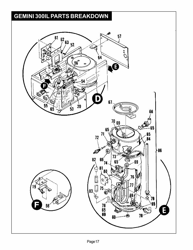
GEMINI 300IL PARTS BREAKDOWN
Page 17

Page 18
DESCRIPTIONINDEX
Nº123456789
1011121314151617
17A18192021222324252627282930313233343536373839404142434445464748495051525354
WC-5450WC-3301WC-3311WC-3963WC-4003WC-3201WC-5451WC-3831WC-37102WC-6732-1WC-4201WC-2912BKWC-2946WC-2947WC-4308WC-4205WC-39009WC-39009-01WC-5424WC-3500WC-37122WC-3766WC- 419WC-5310WC- 400RWC-5452WC-1411WC-2936WC-2945WC-4213WC-4503WC- 827WC- 848WC-3700WC-4616WC-2805WC-4439WC- 200WC- 124WC- 121WC- 122WC- 123WC-38149WC-3234WC- 102WC-3812WC-1408WC-3820WC-1500WC-1501WC-5840WC-3810WC-4501WC- 642WC-4405
PARTNº
Gemini 300IL - Parts List
TOP COVER . . . . . . . . . . . . . . . . . . . . . . . . . . . . . .WIRE BASKET, PB-2 . . . . . . . . . . . . . . . . . . . . . . . . . . .BREW CONE WITH HANDLE . . . . . . . . . . . . . . . . . . . . . . .LABEL, REMOVE BASKET SLOWLY . . . . . . . . . . . . . . . . . . . .NUT, RETAINER . . . . . . . . . . . . . . . . . . . . . . . . . . . . .HANDLE FOR BREW CONE . . . . . . . . . . . . . . . . . . . . . . . .WARMER DECK, NO ELEMENTS . . . . . . . . . . . . . . . . . . . . . .LABEL, CAUTION HOT SURFACE . . . . . . . . . . . . . . . . . . . . .KIT, WARMER ELEMENT 120V, 100W . . . . . . . . . . . . . . . . . . . . .STRAP FOR WARMER ELEMENT . . . . . . . . . . . . . . . . . . . . .NUT, KEP, 8-32 . . . . . . . . . . . . . . . . . . . . . . . . . . . . . .HOT WATER SPOUT ASSEMBLY (OPTIONAL) . . . . . . . . . . . . . . . . . .AERATOR, FEMALE . . . . . . . . . . . . . . . . . . . . . . . . . . . .ADAPTER, MALE . . . . . . . . . . . . . . . . . . . . . . . . . . . . .WASHER, INTERNAL LOCK, 1/2" I.D. . . . . . . . . . . . . . . . . . . .NUT, LOCK, NPS, 1/4" . . . . . . . . . . . . . . . . . . . . . . . . . .PANELS TOP AND BOTTOM . . . . . . . . . . . . . . . . . . . . . . .LABEL, SWITCH PANEL W/O HOT WATER GEM300IL . . . . . . . . . . . . . .BRACKET FAUCET SUPPORT . . . . . . . . . . . . . . . . . . . . . . .LEG, ADJUSTABLE 4" . . . . . . . . . . . . . . . . . . . . . . . . . .KIT, DUMP VALVE RIGHT . . . . . . . . . . . . . . . . . .KIT, REPAIR USE ON WC-820, WC-821,WC-844,WC-880E . . . . . . . . . . . . .COIL, 115V, FOR EATON VALVE . . . . . . . . . . . . . . . . . . . . .TUBING, SILICONE, 5/16" I.D. . . . . . . . . . . . . . . . . . . . . . .POWER RELAY, 115V, 50A . . . . . . . . . . . . . . . . . . . . . . . .COVER, FRONT . . . . . . . . . . . . . . . . . . . . . . . . . . . . .BUSHING, SNAP-IN, 5/8" . . . . . . . . . . . . . . . . . . . . . . . . .SPRAYHEAD, RED . . . . . . . . . . . . . . . . . . . . . . . . . . . .RESTRICTOR, FLOW . . . . . . . . . . . . . . . . . . . . . . . . . . .NUT, LOCK 5/8" . . . . . . . . . . . . . . . . . . . . . . . . . . . . .SCREW, PAN HEAD, 8-32 x 1/2" . . . . . . . . . . . . . . . . . . . . .VALVE, WATER INLET . . . . . . . . . . . . . . . . . . . . . . . . . .WASHER, FLOW, 1 GPM FOR WC- 827 . . . . . . . . . . . . . . . . . .KIT, REPAIR, FOR WC- 827 VALVE . . . . . . . . . . . . . . . . . . . .SCREW, 1/4-20x½ PHILLIPS PAN HEAD SS . . . . . . . . . . . . . . . . . . .FITTING, ELBOW, COMPRESSOR, 3/8" x 3/8" . . . . . . . . . . . . . . .SCREW, 6-32x¼ PHIL PAN HD SS . . . . . . . . . . . . . . . . . . . . . .LIGHT, INDICATOR, 115V . . . . . . . . . . . . . . . . . . . . . . . .SWITCH, ROCKER, HOT WATER, 115V . . . . . . . . . . . . . . . . . .SWITCH, ROCKER, ON/OFF, 115V . . . . . . . . . . . . . . . . . . . .SWITCH, ROCKER, BREW, 115V . . . . . . . . . . . . . . . . . . . . .SWITCH, ROCKER, WARMER, 115V . . . . . . . . . . . . . . . . . . .LABEL, WARNING . . . . . . . . . . . . . . . . . . . . . . . . . . . .GUARD, SWITCH . . . . . . . . . . . . . . . . . . . . . . . . . . . . .SWITCH, TOGGLE, 125V, 80A . . . . . . . . . . . . . . . . . . . . . .LABEL, GROUND . . . . . . . . . . . . . . . . . . . . . . . . . . . . .GRIP, CORD, 7/8" . . . . . . . . . . . . . . . . . . . . . . . . . . . .LABEL, WIRING WARRANTY . . . . . . . . . . . . . . . . . . . . . . .FUSE, 5 AMP . . . . . . . . . . . . . . . . . . . . . . . . . . . . . .FUSE HOLDER . . . . . . . . . . . . . . . . . . . . . . . . . . . . . .COVER, ELECTRIC BOX . . . . . . . . . . . . . . . . . . . . . . . . . .LABEL, CAUTION . . . . . . . . . . . . . . . . . . . . . . . . . . . . .SCREW, 8-32 x 1/4 . . . . . . . . . . . . . . . . . . . . . . . . . . . .TIMER, TRI-BREW . . . . . . . . . . . . . . . . . . . . . . . . . . . .SCREW, PAN HEAD, 6-32 x 7/8 . . . . . . . . . . . . . . . . . . . . . .

Page 19
PRICES SUBJECT TO CHANGE WITHOUT NOTICE
DESCRIPTIONINDEX
NºPART
Nº
Gemini 300IL - Parts List
FITTING, SPRAYHEAD . . . . . . . . . . . . . . . . . . . . . . . . . . . . . . .KIT, VALVE BY-PASS . . . . . . . . . . . . . .PANEL, TOP WRAP BACK G300IL . . . . . . . . . . . . . . . . . . . . . . . . . .THERMOSTAT . . . . . . . . . . . . . . . . . . . . . . . . . . . . . . . . . . . .CIRCUIT BOARD, LIQUID LEVEL CONTROL . . . . . . . . . . . . . . . . . . . .GUARD, SHOCK FOR L.L.C. . . . . . . . . . . . . . . . . . . . . . . . . . . . . .WASHER, LOCK, EXTERNAL #8 . . . . . . . . . . . . . . . . . . . . . . . . . . .BRACKET, UPPER TANK SUPPORT . . . . . . . . . . . . . . . . . . . . . . . . .O' RING, 1/2" . . . . . . . . . . . . . . . . . . . . . . . . . . . . . . . . . . . .FITTING, TANK OVERFLOW . . . . . . . . . . . . . . . . . . . . . . . . . . . . .LID ASSEMBLY FOR HEATING TANK . . . . . . . . . . . . . . . . . . . . . . . .NUT, JAM, 5/8" BRASS . . . . . . . . . . . . . . . . . . . . . . . . . . . . . . .GROMMET, RUBBER, FDA (9101) . . . . . . . . . . . . . . . . . . . . . . . . . .FITTING, HEX PROBE . . . . . . . . . . . . . . . . . . . . . . . . . . . . . . . .PROBE, WATER LEVEL . . . . . . . . . . . . . . . . . . . . . . . . . . . . . . .FITTING, TANK OUTLET . . . . . . . . . . . . . . . . . . . . . . . . . . . . . . .THERMOSTAT, RESET, MR-4 . . . . . . . . . . . . . . . . . . . . . . . . . . . .WASHER, TEFLON, 9/16" I.D. . . . . . . . . . . . . . . . . . . . . . . . . . . . .HEATING ELEMENT, 2000W, 220V . . . . . . . . . . . . . . . . . . . . . . . . .CLIP, THERMOSTAT TO HEATING ELEMENT . . . . . . . . . . . . . . . . . . . . .FITTING, INLET . . . . . . . . . . . . . . . . . . . . . . . . . . . . . . . . . .TUBE ASSEMBLY, HOT WATER TANK . . . . . . . . . . . . . . . . . . . . . . . .SHOCK GUARD FOR HEATING ELEMENT TERMINALS . . . . . . . . . . . . . . . .SHOCK GUARD FOR RESET THERMOSTAT . . . . . . . . . . . . . . . . . . . . .PLUG, DRAIN, TEFLON . . . . . . . . . . . . . . . . . . . . . . . . . . . . . . .CLAMP, HOSE, S/S . . . . . . . . . . . . . . . . . . . . . . . . . . . . . . . . .INSULATION, GEM-230A/300IL . . . . . . . . . . . . . . . . . . . . .HEATING TANK WITH FITTINGS ONLY . . . . . . . . . . . . . . . . . . . . . . .HEATING TANK COMPLETE . . . . . . . . . . . . . . . . . . . . . . . . . . . . .CABLE, INTERLOCK TIMER . . . . . . . . . . . . . . . . . . . . . . . . . . . . .
555657586162636465666769707172737475767778798081828384858687
WC-2977WC-37130WC-6556WC- 517WC- 608WC-4380WC-4329WC-6301WC-4320WC-2948WC-5661WC-4212WC-4314WC-2938WC-5502WC-2935WC- 508WC-4306WC- 906WC-5409WC-29009WC-2956WC-43801WC-4381WC-4398WC-4319WC-3691WC-5453WC-5454WC- 648

Page 20
LISTPRICE
$5.5024.0036.0020.0076.001.508.00
$124.0010.0013.00
239.0026.5018.0011.004.50
LISTPRICEDESCRIPTION
PARTNº
INDEXNº
GEM-5WC-1201WC- 114RGEM 3WC-3307WC-5622WC-2102WC-2010CWC-2025
12345
5A678
SATELLITE WARMER STAND,115V . . . . .POWER CORD 6’ 18/3 BLK . . . . . . . . . .SWITCH, ROCKER 120V RED . . . . . . . . .SATELLITE SERVER 1½ GAL . . . . . . . .LID GEMINI SATELLITE . . . . . . . . . . .LID, SATELLITE PLASTIC GEM3 (OPTIONAL)GAUGE GLASS ASSEMBLY, 8” C . . . . . .SHIELD, 8 INCH GAUGE GLASS . . . . . . .GAUGE GLASS, 8 INCH . . . . . . . . . . .
DESCRIPTIONPART
NºINDEX
Nº9
1011
11A12131415
WC-2007WC-1901WC-1800WC-1841WC-3705GEM 4WC-3503WC-37102
BRACKET, GAUGE GLASS FORMED . . . . .SHANK, FAUCET D&T CHROME . . . . . .FAUCET S’ NONLOCKING . . . . . . . . .FAUCET, "ESP" BLACK NONLOCKING (OPTNL)KIT FAUCET S’ SERIES . . . . . . . . . . .SATELLITE STAND . . . . . . . . . . . . .LEG, SCREW BUMPER 3/8"-16 STD . . . .KIT, WARMER ELEMENT 100W 120VAC . . .
120 Volts, 90 WattsWiring Diagram Gem -5 & -8
BLACK
GRN
POWER CORD
WHITE3A
5B 4BWARMER
SWITCHWHITE
REDWARMER ELEMENT
ILLUSTRAILLUSTRAILLUSTRAILLUSTRAILLUSTRATED PTED PTED PTED PTED PARARARARARTS BREAKDOWN GEM-3,TS BREAKDOWN GEM-3,TS BREAKDOWN GEM-3,TS BREAKDOWN GEM-3,TS BREAKDOWN GEM-3, -5, -5, -5, -5, -5, -8 -8 -8 -8 -8
11
13
12
10
9
14
171
3
4
5
2
15
6 7
8

Page 21

Page 22

Page 23

Page 24

Printed in U.S.A. 8/27/03 F-1901 rev B
WARRANTY
FOR THE LATEST SPECIFICATION INFORMATION GO TO WWW.WILBURCURTIS.COM
WILBUR CURTIS CO., INC.6913 Acco St., Montebello, CA 90640-5403 USAPhone: 800/421-6150 Fax: 323-837-2410 Technical Support Phone: 800/995-0417 (M-F 5:30A - 4:00P PST) E-Mail: [email protected] Web Site: www.wilburcurtis.com
We hereby certify that the products manufactured by the Wilbur Curtis Company, Inc., are, to thebest of our knowledge,free from all defects and faulty workmanship.The following warranties and conditions are applicable:
1. 1 Year Parts & Labor from Date of Purchase from Factory: This warranty covers all electrical parts, fittingsand tubing.
2. 40 Months or 40, 000 Pounds of Coffee on a set of Grinding Burrs. (ADS Grinders)3. 3 Years from Date of Purchase: This warranty covers electronic control boards and leaking or pitting of a
stainless steel body of a Brewer or Urn.4. 90 Days from Date of Purchase: On replacement parts that have been installed on out of warranty equipment
All in-warranty service calls must have prior authorization from the manufacturer. For an RMA (Return MerchandiseAuthorization) number, call the Technical Service Department at 1-800-995-0417. The Wilbur Curtis Company will allowup to 100 miles, round trip, per in-warranty service call.CONDITIONS & EXCEPTIONSThe warranty covers original equipment at time of purchase only. The Wilbur Curtis Company, Inc., assumes noresponsibility for substitute replacement parts installed on Curtis equipment that have not been purchased from theWilbur Curtis Company. Inc The Wilbur Curtis Company will not accept any responsibility if the following conditions are notmet. The warranty does not cover and is void under these circumstances:
1) Improper operation of equipment. The equipment must be used for its designed and intendedpurpose and function.
2) Improper installation of equipment. This equipment must be installed by a professional,certified technician and must comply with all local electrical, mechanical and plumbing codes.
3) Wilbur Curtis Company will not be responsible for the operation of equipment at other than thestated voltages on the serial plate.
4) Abuse or neglect (including failure to periodically clean or remove lime accumulations).Manufacturer is not responsible for variation in equipment operation due to excessive lime orlocal water conditions.
5) Replacement of items subject to normal use and wear. This shall include, but is not limited to,light bulbs, shear disks, “0” rings, gaskets, canister assemblies. whipper chambers and plates,mixing bowls, agitation assemblies and whipper propellers.
6) Any faults resulting from inadequate water supply. This includes, but is not limited to, exces-sive or low water pressure, and inadequate or fluctuating water flow rate.
7) All repairs and/or replacements are subject to our decision that the workmanship or parts werefaulty and the defects showed up under normal use.
8) All labor shall be performed during regular working hours. Overtime charges are the responsibil-ity of the owner.
9) Charges incurred by delays, waiting time, or operating restrictions that hinder the servicetechnician’s ability to perform service is the responsibility of the owner of the equipment.This includes institutional and correctional facilities.
10) All claims under this warranty must be submitted to the Wilbur Curtis Company TechnicalService Department before return of the unit to the factory.
11) All equipment returned to us must be repackaged properly in the original carton. No units willbe accepted if they are damaged in transit due to improper packaging.
12) Damaged in transit.13) The resetting of safety thermostats and circuit breakers, programming and temperature
adjustments are the responsibility of the equipment owner.
NO UNITS OR PARTS WILL BE ACCEPTED WITHOUT A RETURN MERCHANDISE AUTHORIZATION (RMA).RMA NUMBER MUST BE MARKED ON THE CARTON OR SHIPPING LABEL.All in-warranty service calls must be performed by an authorized service center, where service is available. Call the factoryfor location near you.