service manual - hoshizaki manual number: 73191 issued: 9-29-2011 revised: 9-7-2017...
TRANSCRIPT
ModelsUndercounterWorktopPrep Table
Commercial Series Refrigerated Kitchen Equipment
Service Manual
Number: 73191Issued: 9-29-2011Revised: 9-7-2017
hoshizakiamerica.com
2
WARNINGOnly qualified service technicians should install and service the appliance. To obtain the name and phone number of your local Hoshizaki Certified Service Representative, visit www.hoshizaki.com. No service should be undertaken until the technician has thoroughly read this Service Manual. Failure to service and maintain the appliance in accordance with this manual will adversely affect safety, performance, component life, and warranty coverage. Proper installation is the responsibility of the installer. Product failure or property damage due to improper installation is not covered under warranty.
Hoshizaki provides this manual primarily to assist qualified service technicians in the service of the appliance.
Should the reader have any questions or concerns which have not been satisfactorily addressed, please call, send an e-mail message, or write to the Hoshizaki Technical Support Department for assistance.
Phone: 1-800-233-1940; (770) 487-2331Fax: 1-800-843-1056; (770) 487-3360
E-mail: [email protected]
618 Highway 74 SouthPeachtree City, GA 30269Attn: Hoshizaki Technical Support Department
Web Site: www.hoshizaki.com
NOTE: To expedite assistance, all correspondence/communication MUST include the following information:
• Model Number
• Serial Number
• Complete and detailed explanation of the problem.
3
IMPORTANTThis manual should be read carefully before the appliance is serviced. Read the warnings and guidelines contained in this booklet carefully as they provide essential information for the continued safe use, service, and maintenance of the appliance. Retain this booklet for any further reference that may be necessary.
CONTENTSImportant Safety Information ................................................................................................. 5I. Construction and Refrigeration Circuit Diagram ................................................................. 8
A. Construction .................................................................................................................. 8B. Refrigeration Circuit Diagram ........................................................................................ 9
II. Sequence of Operation and Service Diagnosis ............................................................... 10A1. Thermostat Control Sequence of Operation Flow Chart ............................................ 10
1. Undercounter and Work Top: Refrigerator .............................................................. 102. Prep Table ...............................................................................................................113. Undercounter and Work Top: Freezer .....................................................................11
A2. Thermistor/Control Module Sequence of Operation Flow Chart ............................... 121. Undercounter and Work Top: Refrigerator .............................................................. 122. Prep Table .............................................................................................................. 133. Undercounter and Work Top: Freezer .................................................................... 14
B1. Thermostat Control Service Diagnosis ...................................................................... 151. Undercounter and Worktop: Refrigerator ................................................................ 152. Prep Table .............................................................................................................. 163. Undercounter and Worktop: Freezer ...................................................................... 17
B2. Thermistor/Control Module Service Diagnosis .......................................................... 19C. Defrost Timer Check ................................................................................................... 23D. Control Module Check ................................................................................................. 24E. Diagnostic Table .......................................................................................................... 26
III. Controls and Adjustments ............................................................................................... 28A. Temperature Settings .................................................................................................. 28B. Defrost ......................................................................................................................... 28C. Safety Devices ............................................................................................................ 30D. Perimeter and Mullion Heaters .................................................................................... 30
IV. Refrigeration Circuit and Component Service Information.............................................. 31A. Refrigeration Circuit Service Information .................................................................... 31B. Component Service Information .................................................................................. 33C. Door Reversal ............................................................................................................. 34D. Door/Drawer Location Reversal .................................................................................. 37
V. Preparing the Appliance for Periods of Non-Use ............................................................. 48VI. Disposal .......................................................................................................................... 49
4
VII. Technical Information ..................................................................................................... 50A. Electrical and Refrigerant Data ................................................................................... 50B. Wiring Diagrams .......................................................................................................... 51
1a. Undercounter and Worktop: Refrigerator; Cabinet Thermostat ............................ 511b. Undercounter and Worktop: Refrigerator; Cabinet Thermistor/Control Module .... 522a. Prep Table; Cabinet Thermostat (Without Defrost Heater) ................................... 532b. Prep Table; Cabinet Thermostat (With Defrost Heater) ........................................ 542c. Prep Table; Cabinet Thermistor/Control Module ................................................... 553a. Undercounter and Work Top: Freezer; Cabinet Thermostat ................................. 563b. Undercounter and Work Top: Freezer; Cabinet Thermistor/Control Module ......... 57
5
Important Safety InformationThroughout this manual, notices appear to bring your attention to situations which could result in death, serious injury, damage to the appliance, or damage to property.
WARNING Indicates a hazardous situation which could result in death or serious injury.
NOTICE Indicates a situation which could result in damage to the appliance or property.
IMPORTANT Indicates important information about the use and care of the appliance.
WARNINGThis appliance should be destined only to the use for which it has been expressly conceived. Any other use should be considered improper and therefore dangerous. The manufacturer cannot be held responsible for injury or damage resulting from improper, incorrect, and unreasonable use. Failure to service and maintain the appliance in accordance with this manual will adversely affect safety, performance, component life, and warranty coverage.To reduce the risk of death, electric shock, serious injury, or fire, follow basic precautions including the following:
• Only qualified service technicians should install and service this appliance.
• This appliance must be installed in accordance with applicable national, state, and local codes and regulations.
• To reduce the risk of electric shock, do not touch the plug with damp hands.
• Unplug the appliance before servicing.
• This appliance requires an independent power supply of proper capacity. See the nameplate for electrical specifications. Failure to use an independent power supply of proper capacity can result in a tripped breaker, blown fuse, damage to existing wiring, or component failure. This could lead to heat generation or fire.
• THIS APPLIANCE MUST BE GROUNDED. This appliance is equipped with a NEMA 5-15 three-prong grounding plug to reduce the risk of potential shock hazards. It must be plugged into a properly grounded, independent 3-prong wall outlet. If the outlet is a 2-prong outlet, it is your personal responsibility to have a qualified electrician replace it with a properly grounded, independent 3-prong wall outlet. Do not remove the ground prong from the power cord and do not use an adapter plug. Failure to follow these instructions may result in death, electric shock, or fire.
• Do not use an extension cord.
• Do not use an appliance with a damaged power cord. The power cord should not be altered, jerked, bundled, weighed down, pinched, or tangled. Such actions could result in electric shock or fire. To unplug the appliance, be sure to pull the plug, not the cord, and do not jerk the cord.
6
WARNING, continued • The GREEN ground wire in the factory-installed power cord is connected to the
appliance. If it becomes necessary to remove or replace the power cord, be sure to connect the power cord's ground wire.
• Do not splash, pour, or spray water directly onto or into the appliance. This might cause short circuit, electric shock, corrosion, or failure.
• Do not make any alterations to the appliance. Alterations could result in electric shock, injury, fire, or damage to the appliance.
• This appliance is not intended for use by persons (including children) with reduced physical, sensory, or mental capabilities, or lack of experience and knowledge, unless they have been given supervision or instruction concerning use of the appliance by a person responsible for their safety.
• Children should be properly supervised around this appliance.
• Do not climb, stand, or hang on the appliance or door or allow children or animals to do so. Do not climb into the appliance or allow children or animals to do so. Death or serious injury could occur or the appliance could be damaged.
• Be careful not to pinch fingers when opening and closing the doors or rail cover (prep table models). Be careful when opening and closing the doors or rail cover when children are in the area.
• Open and close the doors and rail cover (prep table models) with care. Opening the doors or rail cover too quickly or forcefully may cause injury or damage to the appliance or surrounding equipment.
• Do not use combustible spray or place volatile or flammable substances in or near the appliance. They might catch fire.
• Keep the area around the appliance clean. Dirt, dust, or insects in the appliance could cause harm to individuals or damage to the equipment.
• Do not throw anything onto the shelves or load any single shelf with more than 120 lb. (54.5 kg) of product. They might fall off and cause injury.
• This appliance is designed only for temporary storage of food. Employ sanitary methods. Use for any other purposes (for example, storage of chemicals or medical supplies such as vaccine and serum) could cause deterioration of stored items.
• Do not block air inlets or outlets, otherwise cooling performance may be reduced.
• Do not tightly pack the cabinet. Allow some space between items to ensure good air flow. Also allow space between items and interior surfaces.
• Do not put warm or hot foods in the cabinet. Let them cool first, or they will raise the cabinet temperature and could deteriorate other foods in the cabinet or overload the appliance.
7
WARNING, continued• All foods should be wrapped in plastic film or stored in sealed containers.
Otherwise foods may dry up, pass their smells onto other foods, cause frost to develop, result in poor appliance performance, or increase the likelihood of cross-contamination. Certain dressings and food ingredients, if not stored in sealed containers, may accelerate corrosion of the evaporator, resulting in failure.
• Do not store items near air outlets. Otherwise, items may freeze up and crack or break causing a risk of injury or contamination of other food.
Additional Warnings for Prep Table Models
• The entire rail must always be covered by rail dividers and pans (1/6 size, up to 6" (15 cm) deep). Otherwise, the appliance will not cool properly.
• Use only 1/6 size pans up to 6" (15 cm) deep. Do not use damaged pans.
• Ingredients must be pre-chilled to 37°F (3°C) or less before placing in rail.
• Keep the rail cover closed when not actively preparing food.
• The rail is for keeping ingredients cool while preparing food. If not actively preparing food for a long period such as overnight, seal pans with plastic wrap in addition to closing the rail cover. Depending on conditions, the cabinet temperature setting may need to be adjusted to prevent items from freezing. Alternatively, seal ingredients and store them in a refrigerator or freezer.
NOTICE• Protect the floor when moving the appliance to prevent damage to the floor.
• Keep ventilation openings, in the appliance enclosure or in the built-in structure, clear of obstruction. Do not place anything on top of the appliance in an undercounter installation. There must be at least 1.5" (4 cm) overhead clearance for proper ventilation. The factory-installed rear bumpers must be in place to ensure proper rear clearance. Blockage of airflow could negatively affect performance and damage the appliance.
• Do not allow the appliance to bear any outside weight.
• To prevent deformation or cracks, do not spray insecticide onto the plastic parts or let them come into contact with oil.
• To avoid damage to the gasket, use only the door handle when opening and closing.
• To avoid damage to the top seal, do not lift the appliance by the top panel or remove the top panel.
Additional Notice for Prep Table and Mega Top Models
• Do not place anything on top of the rail hood or rail cover and do not lift the appliance by the rail hood or rail cover. The rail hood and rail cover are not designed to bear any outside weight.
• CRMR27-8(-12M) Auxiliary Code B-5 to C-7: Do not place anything on the air distribution table beneath the pans. The air distribution table is not a load-bearing surface.
8
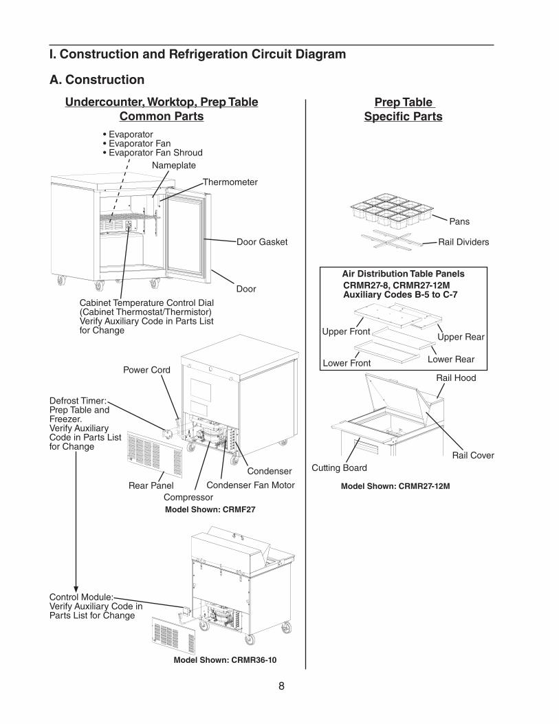
I. Construction and Refrigeration Circuit Diagram
A. Construction
Power Cord
CompressorCondenser Fan Motor
Condenser
Rear Panel
Defrost Timer: Prep Table and Freezer. Verify Auxiliary Code in Parts List for Change
Thermometer
Door
Door Gasket
Nameplate
• Evaporator• Evaporator Fan• Evaporator Fan Shroud
Cabinet Temperature Control Dial(Cabinet Thermostat/Thermistor) Verify Auxiliary Code in Parts List for Change
Pans
Rail Dividers
Upper Front Upper Rear
Lower RearLower Front
Rail Cover
Air Distribution Table Panels
Undercounter, Worktop, Prep TableCommon Parts
Prep Table Specific Parts
Model Shown: CRMF27
Model Shown: CRMR27-12M
Rail Hood
Cutting Board
CRMR27-8, CRMR27-12M Auxiliary Codes B-5 to C-7
Model Shown: CRMR36-10
Control Module:Verify Auxiliary Code in Parts List for Change
9
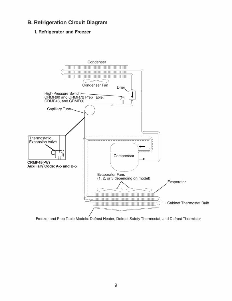
B. Refrigeration Circuit Diagram
1. Refrigerator and Freezer
Evaporator Fans(1, 2, or 3 depending on model)
Evaporator
Compressor
DrierCondenser Fan
Condenser
Freezer and Prep Table Models: Defrost Heater, Defrost Safety Thermostat, and Defrost Thermistor
Cabinet Thermostat Bulb
Capillary Tube
High-Pressure SwitchCRMR60 and CRMR72 Prep Table, CRMF48, and CRMF60
Thermostatic Expansion Valve
CRMF48(-W) Auxiliary Code: A-5 and B-5
10
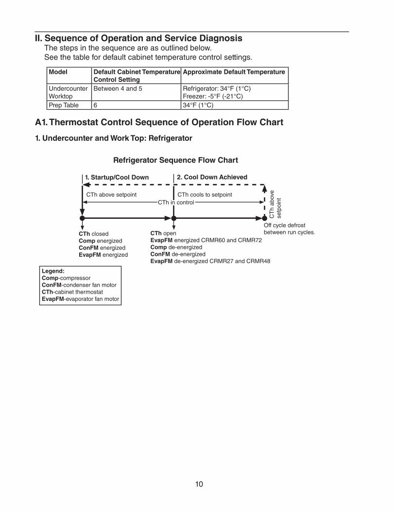
II. Sequence of Operation and Service DiagnosisThe steps in the sequence are as outlined below.See the table for default cabinet temperature control settings.
Model Default Cabinet Temperature Control Setting
Approximate Default Temperature
UndercounterWorktop
Between 4 and 5 Refrigerator: 34°F (1°C) Freezer: -5°F (-21°C)
Prep Table 6 34°F (1°C)
A1. Thermostat Control Sequence of Operation Flow Chart
1. Undercounter and Work Top: Refrigerator
Refrigerator Sequence Flow Chart
1. Startup/Cool Down 2. Cool Down Achieved
CTh closed Comp energizedConFM energizedEvapFM energized
CTh openEvapFM energized CRMR60 and CRMR72Comp de-energizedConFM de-energized EvapFM de-energized CRMR27 and CRMR48
CTh in controlCTh above setpoint CTh cools to setpoint
CT
h ab
ove
setp
oint
Off cycle defrost between run cycles.
Legend:Comp-compressorConFM-condenser fan motorCTh-cabinet thermostatEvapFM-evaporator fan motor
11
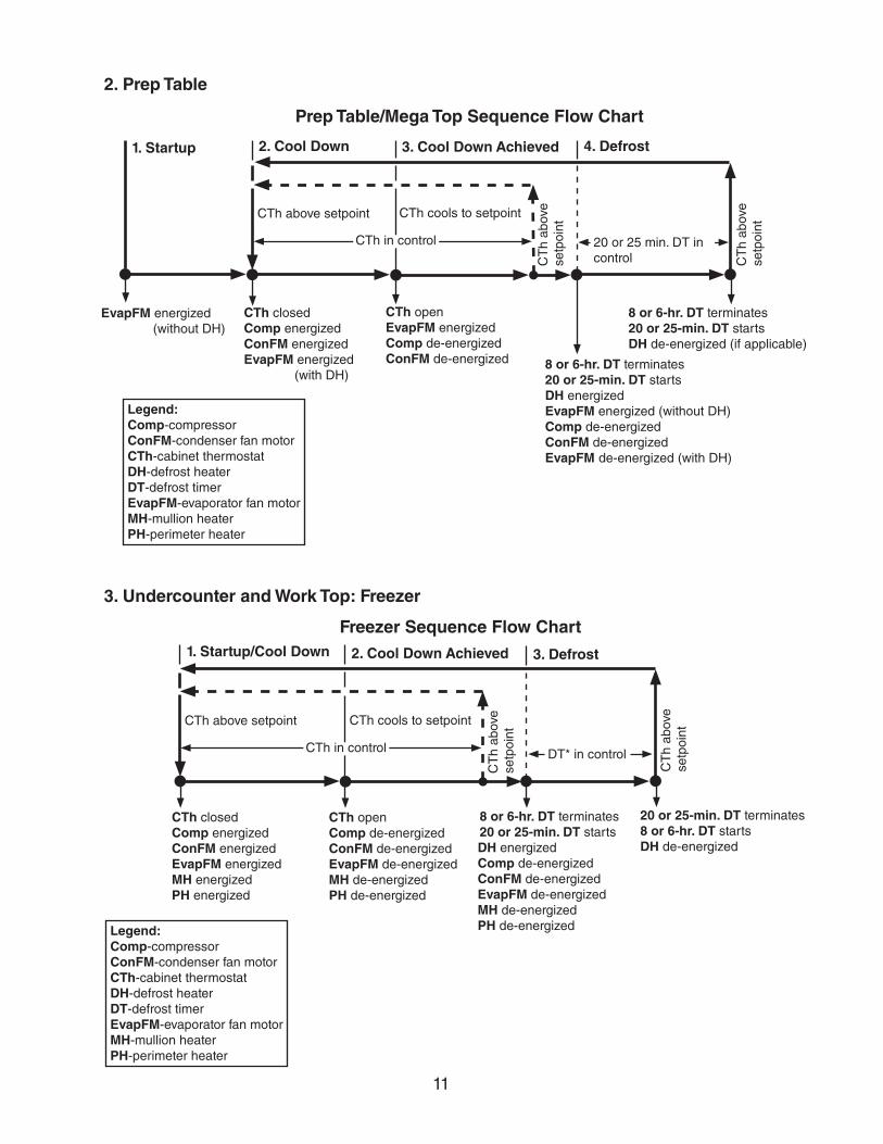
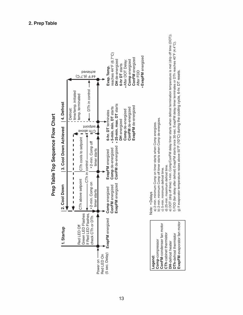
2. Prep Table
Prep Table/Mega Top Sequence Flow Chart
2. Cool Down 3. Cool Down Achieved
CTh closedComp energizedConFM energizedEvapFM energized (with DH)
CTh openEvapFM energizedComp de-energizedConFM de-energized
4. Defrost
8 or 6-hr. DT terminates20 or 25-min. DT startsDH de-energized (if applicable)
CTh above setpoint CTh cools to setpoint
CT
h ab
ove
setp
oint
CT
h ab
ove
setp
oint
20 or 25 min. DT in control
CTh in control
1. Startup
EvapFM energized (without DH)
8 or 6-hr. DT terminates20 or 25-min. DT startsDH energized EvapFM energized (without DH) Comp de-energizedConFM de-energizedEvapFM de-energized (with DH)
Legend:Comp-compressorConFM-condenser fan motorCTh-cabinet thermostatDH-defrost heaterDT-defrost timerEvapFM-evaporator fan motorMH-mullion heaterPH-perimeter heater
Freezer Sequence Flow Chart1. Startup/Cool Down 2. Cool Down Achieved
CTh closedComp energizedConFM energizedEvapFM energizedMH energizedPH energized
CTh openComp de-energizedConFM de-energizedEvapFM de-energizedMH de-energizedPH de-energized
3. Defrost
8 or 6-hr. DT terminates20 or 25-min. DT startsDH energized Comp de-energizedConFM de-energizedEvapFM de-energizedMH de-energizedPH de-energized
20 or 25-min. DT terminates8 or 6-hr. DT startsDH de-energized
CTh in control
CTh above setpoint CTh cools to setpoint
CT
h ab
ove
setp
oint
CT
h ab
ove
setp
oint
DT* in control
Legend:Comp-compressorConFM-condenser fan motorCTh-cabinet thermostatDH-defrost heaterDT-defrost timerEvapFM-evaporator fan motorMH-mullion heaterPH-perimeter heater
3. Undercounter and Work Top: Freezer
12
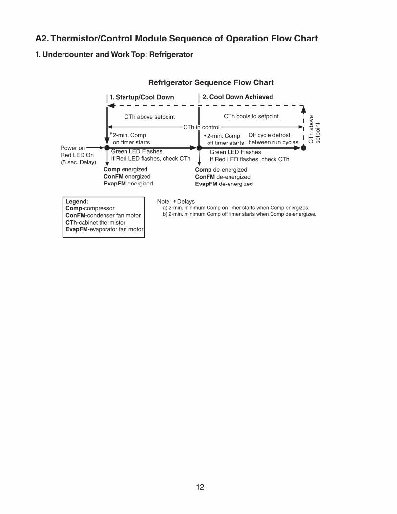
A2. Thermistor/Control Module Sequence of Operation Flow Chart
1. Undercounter and Work Top: Refrigerator
1. Startup/Cool Down 2. Cool Down Achieved
Comp energizedConFM energizedEvapFM energized
Comp de-energizedConFM de-energizedEvapFM de-energized
CTh in controlOff cycle defrost between run cycles
Refrigerator Sequence Flow Chart
2-min. Comp on timer starts
2-min. Comp off timer starts
Legend:Comp-compressorConFM-condenser fan motorCTh-cabinet thermistorEvapFM-evaporator fan motor
Power onRed LED On (5 sec. Delay)
Green LED Flashes If Red LED flashes, check CTh
Green LED Flashes If Red LED flashes, check CTh
CTh above setpoint CTh cools to setpoint
CT
h ab
ove
setp
oint
Note: Delaysa) 2-min. minimum Comp on timer starts when Comp energizes.b) 2-min. minimum Comp off timer starts when Comp de-energizes.
*
* *
13
2. Prep Table
Pre
p T
able
To
p S
equ
ence
Flo
w C
har
t
2. C
oo
l Do
wn
3. C
oo
l Do
wn
Ach
ieve
d
Co
mp
ene
rgiz
edC
on
FM
ene
rgiz
edE
vap
FM
ene
rgiz
ed
Eva
pF
M e
nerg
ized
Co
mp
de-
ener
gize
dC
on
FM
de-
ener
gize
d
4. D
efro
st
CT
h ab
ove
setp
oint
CT
h co
ols
to s
etpo
int
CTh above setpoint
44°F (6.7°C)achieved
CT
h in
con
trol
1. S
tart
up
Eva
pF
M e
nerg
ized
6-h
r. D
T te
rmin
ates
5-
min
. min
. DT
sta
rts
25-m
in. m
ax. D
T s
tart
sD
H e
nerg
ized
C
om
p d
e-en
ergi
zed
Co
nF
M d
e-en
ergi
zed
Eva
pF
M d
e-en
ergi
zed
Def
rost
: tim
e/te
mp.
initi
ated
te
mp.
term
inat
ed
Pow
er o
nR
ed L
ED
On
(5 s
ec. D
elay
)
Red
LE
D O
ffG
reen
LE
D F
lash
es
If R
ed L
ED
Fla
shes
, ch
eck
CT
h or
DT
h
Leg
end
:C
om
p-c
ompr
esso
rC
on
FM
-con
dens
er fa
n m
otor
CT
h-c
abin
et th
erm
isto
rD
H-d
efro
st h
eate
rD
Th
-def
rost
ther
mis
tor
Eva
pF
M-e
vapo
rato
r fa
n m
otor
Not
e:
Del
ays
a) 2
-min
. min
imum
Com
p on
tim
er s
tart
s w
hen
Com
p en
ergi
zes.
b) 2
-min
. min
imum
Com
p of
f tim
er s
tart
s w
hen
Com
p de
-ene
rgiz
es.
c) 5
-min
. min
imum
def
rost
tim
e.d)
25-
min
. max
imum
def
rost
tim
e.e)
DO
T (
drip
off
time)
1-m
in. C
omp/
Con
FM
del
ay ti
mer
sta
rts
whe
n de
fros
t ter
min
atio
n te
mpe
ratu
re is
met
(dr
ip o
ff tim
e (D
OT
)).
f) F
DD
(fa
n de
lay
afte
r de
fros
t) E
vapF
M s
tart
s on
ce 3
0-se
c. E
vapF
M d
elay
tim
er te
rmin
ates
or
DT
h re
ache
s 40
°F (
4.4°
C).
g) If
eva
pora
tor
tem
pera
ture
rai
ses
abov
e 50
°F (
10°C
) du
ring
the
cool
ing
cycl
e, 6
-hr.
DT
res
ets.
*
2-m
in. C
omp
off
timer
sta
rts
2-m
in. C
omp
on
timer
sta
rts
Eva
p. T
emp
. re
ache
s 44
°F (
6.7°
C)
DH
de-
ener
gize
d6-
hr
DT
sta
rts
Afte
r D
OT
Del
ay:
Co
mp
ene
rgiz
edC
on
FM
ene
rgiz
edA
fter
FD
DE
vap
FM
ene
rgiz
ed
* *
*
*
* *
DT
h in
con
trol
14
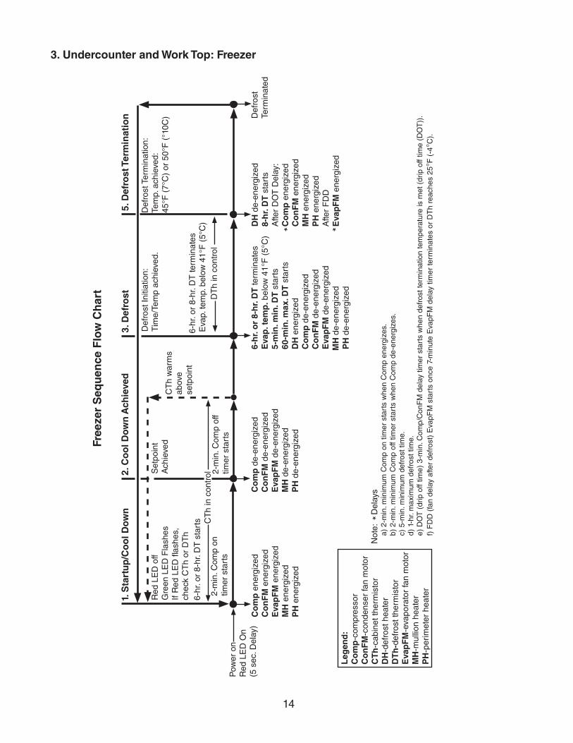
3. Undercounter and Work Top: Freezer
Free
zer
Seq
uen
ce F
low
Ch
art
Leg
end
:C
om
p-c
ompr
esso
rC
on
FM
-con
dens
er fa
n m
otor
CT
h-c
abin
et th
erm
isto
rD
H-d
efro
st h
eate
rD
Th
-def
rost
ther
mis
tor
Eva
pF
M-e
vapo
rato
r fa
n m
otor
MH
-mul
lion
heat
erP
H-p
erim
eter
hea
ter
1. S
tart
up
/Co
ol D
ow
n2.
Co
ol D
ow
n A
chie
ved
Co
mp
ene
rgiz
edC
on
FM
ene
rgiz
edE
vap
FM
ene
rgiz
edM
H e
nerg
ized
PH
ene
rgiz
ed
CT
h in
con
trolS
etpo
int
Ach
ieve
dC
Th
war
ms
abov
e se
tpoi
nt
3. D
efro
st
Co
mp
de-
ener
gize
dC
on
FM
de-
ener
gize
dE
vap
FM
de-
ener
gize
dM
H d
e-en
ergi
zed
PH
de-
ener
gize
d
5. D
efro
st T
erm
inat
ion
DT
h in
con
trol
2-m
in. C
omp
off
timer
sta
rts
2-m
in. C
omp
on
timer
sta
rts
6-hr
. or
8-hr
. DT
sta
rts
Def
rost
Ter
min
atio
n:Te
mp.
ach
ieve
d:45
°F (
7°C
) or
50°
F (
°10C
)
6-h
r. o
r 8-
hr.
DT
term
inat
es
Eva
p. t
emp
. bel
ow 4
1°F
(5°
C)
5-m
in. m
in. D
T s
tart
s60
-min
. max
. DT
sta
rts
DH
ene
rgiz
edC
om
p d
e-en
ergi
zed
Co
nF
M d
e-en
ergi
zed
Eva
pF
M d
e-en
ergi
zed
MH
de-
ener
gize
dP
H d
e-en
ergi
zed
Def
rost
Initi
atio
n:
Tim
e/Te
mp
achi
eved
.
Not
e:
Del
ays
a) 2
-min
. min
imum
Com
p on
tim
er s
tart
s w
hen
Com
p en
ergi
zes.
b) 2
-min
. min
imum
Com
p of
f tim
er s
tart
s w
hen
Com
p de
-ene
rgiz
es.
c) 5
-min
. min
imum
def
rost
tim
e.d)
1-h
r. m
axim
um d
efro
st ti
me.
e) D
OT
(dr
ip o
ff tim
e) 3
-min
. Com
p/C
onF
M d
elay
tim
er s
tart
s w
hen
defr
ost t
erm
inat
ion
tem
pera
ture
is m
et (
drip
off
time
(DO
T))
. f)
FD
D (
fan
dela
y af
ter
defr
ost)
Eva
pFM
sta
rts
once
7-m
inut
e E
vapF
M d
elay
tim
er te
rmin
ates
or
DT
h re
ache
s 25
°F (
-4°C
).
*
DH
de-
ener
gize
d8-
hr.
DT
sta
rts
Afte
r D
OT
Del
ay:
Co
mp
ene
rgiz
edC
on
FM
ene
rgiz
edM
H e
nerg
ized
PH
ene
rgiz
edA
fter
FD
DE
vap
FM
ene
rgiz
ed
* *
Def
rost
Te
rmin
ated
6-hr
. or
8-hr
. DT
term
inat
esE
vap.
tem
p. b
elow
41°
F (
5°C
)
Pow
er o
nR
ed L
ED
On
(5 s
ec. D
elay
)
Red
LE
D o
ffG
reen
LE
D F
lash
es
If R
ed L
ED
flas
hes,
ch
eck
CT
h or
DT
h
15
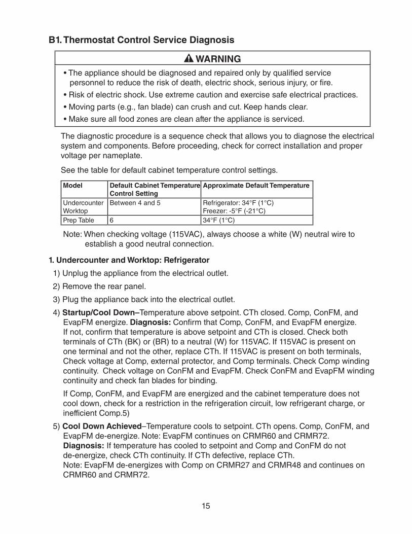
B1. Thermostat Control Service Diagnosis
WARNING• The appliance should be diagnosed and repaired only by qualified service
personnel to reduce the risk of death, electric shock, serious injury, or fire.
• Risk of electric shock. Use extreme caution and exercise safe electrical practices.
• Moving parts (e.g., fan blade) can crush and cut. Keep hands clear.
• Make sure all food zones are clean after the appliance is serviced.
The diagnostic procedure is a sequence check that allows you to diagnose the electrical system and components. Before proceeding, check for correct installation and proper voltage per nameplate.
See the table for default cabinet temperature control settings.
Model Default Cabinet Temperature Control Setting
Approximate Default Temperature
UndercounterWorktop
Between 4 and 5 Refrigerator: 34°F (1°C) Freezer: -5°F (-21°C)
Prep Table 6 34°F (1°C)
Note: When checking voltage (115VAC), always choose a white (W) neutral wire to establish a good neutral connection.
1. Undercounter and Worktop: Refrigerator
1) Unplug the appliance from the electrical outlet.
2) Remove the rear panel.
3) Plug the appliance back into the electrical outlet.
4) Startup/Cool Down–Temperature above setpoint. CTh closed. Comp, ConFM, and EvapFM energize. Diagnosis: Confirm that Comp, ConFM, and EvapFM energize. If not, confirm that temperature is above setpoint and CTh is closed. Check both terminals of CTh (BK) or (BR) to a neutral (W) for 115VAC. If 115VAC is present on one terminal and not the other, replace CTh. If 115VAC is present on both terminals, Check voltage at Comp, external protector, and Comp terminals. Check Comp winding continuity. Check voltage on ConFM and EvapFM. Check ConFM and EvapFM winding continuity and check fan blades for binding.
If Comp, ConFM, and EvapFM are energized and the cabinet temperature does not cool down, check for a restriction in the refrigeration circuit, low refrigerant charge, or inefficient Comp.5)
5) Cool Down Achieved–Temperature cools to setpoint. CTh opens. Comp, ConFM, and EvapFM de-energize. Note: EvapFM continues on CRMR60 and CRMR72. Diagnosis: If temperature has cooled to setpoint and Comp and ConFM do not de-energize, check CTh continuity. If CTh defective, replace CTh. Note: EvapFM de-energizes with Comp on CRMR27 and CRMR48 and continues on CRMR60 and CRMR72.
16
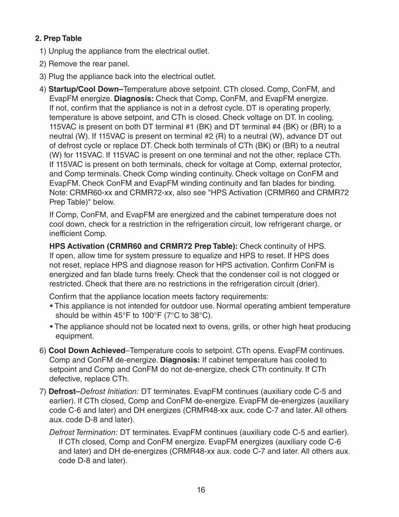
2. Prep Table
1) Unplug the appliance from the electrical outlet.
2) Remove the rear panel.
3) Plug the appliance back into the electrical outlet.
4) Startup/Cool Down–Temperature above setpoint. CTh closed. Comp, ConFM, and EvapFM energize. Diagnosis: Check that Comp, ConFM, and EvapFM energize. If not, confirm that the appliance is not in a defrost cycle. DT is operating properly, temperature is above setpoint, and CTh is closed. Check voltage on DT. In cooling, 115VAC is present on both DT terminal #1 (BK) and DT terminal #4 (BK) or (BR) to a neutral (W). If 115VAC is present on terminal #2 (R) to a neutral (W), advance DT out of defrost cycle or replace DT. Check both terminals of CTh (BK) or (BR) to a neutral (W) for 115VAC. If 115VAC is present on one terminal and not the other, replace CTh. If 115VAC is present on both terminals, check for voltage at Comp, external protector, and Comp terminals. Check Comp winding continuity. Check voltage on ConFM and EvapFM. Check ConFM and EvapFM winding continuity and fan blades for binding.Note: CRMR60-xx and CRMR72-xx, also see "HPS Activation (CRMR60 and CRMR72 Prep Table)" below.
If Comp, ConFM, and EvapFM are energized and the cabinet temperature does not cool down, check for a restriction in the refrigeration circuit, low refrigerant charge, or inefficient Comp.
HPS Activation (CRMR60 and CRMR72 Prep Table): Check continuity of HPS. If open, allow time for system pressure to equalize and HPS to reset. If HPS does not reset, replace HPS and diagnose reason for HPS activation. Confirm ConFM is energized and fan blade turns freely. Check that the condenser coil is not clogged or restricted. Check that there are no restrictions in the refrigeration circuit (drier).
Confirm that the appliance location meets factory requirements:• This appliance is not intended for outdoor use. Normal operating ambient temperature
should be within 45°F to 100°F (7°C to 38°C).• The appliance should not be located next to ovens, grills, or other high heat producing
equipment.
6) Cool Down Achieved–Temperature cools to setpoint. CTh opens. EvapFM continues. Comp and ConFM de-energize. Diagnosis: If cabinet temperature has cooled to setpoint and Comp and ConFM do not de-energize, check CTh continuity. If CTh defective, replace CTh.
7) Defrost–Defrost Initiation: DT terminates. EvapFM continues (auxiliary code C-5 and earlier). If CTh closed, Comp and ConFM de-energize. EvapFM de-energizes (auxiliary code C-6 and later) and DH energizes (CRMR48-xx aux. code C-7 and later. All others aux. code D-8 and later).
Defrost Termination: DT terminates. EvapFM continues (auxiliary code C-5 and earlier). If CTh closed, Comp and ConFM energize. EvapFM energizes (auxiliary code C-6 and later) and DH de-energizes (CRMR48-xx aux. code C-7 and later. All others aux. code D-8 and later).
17
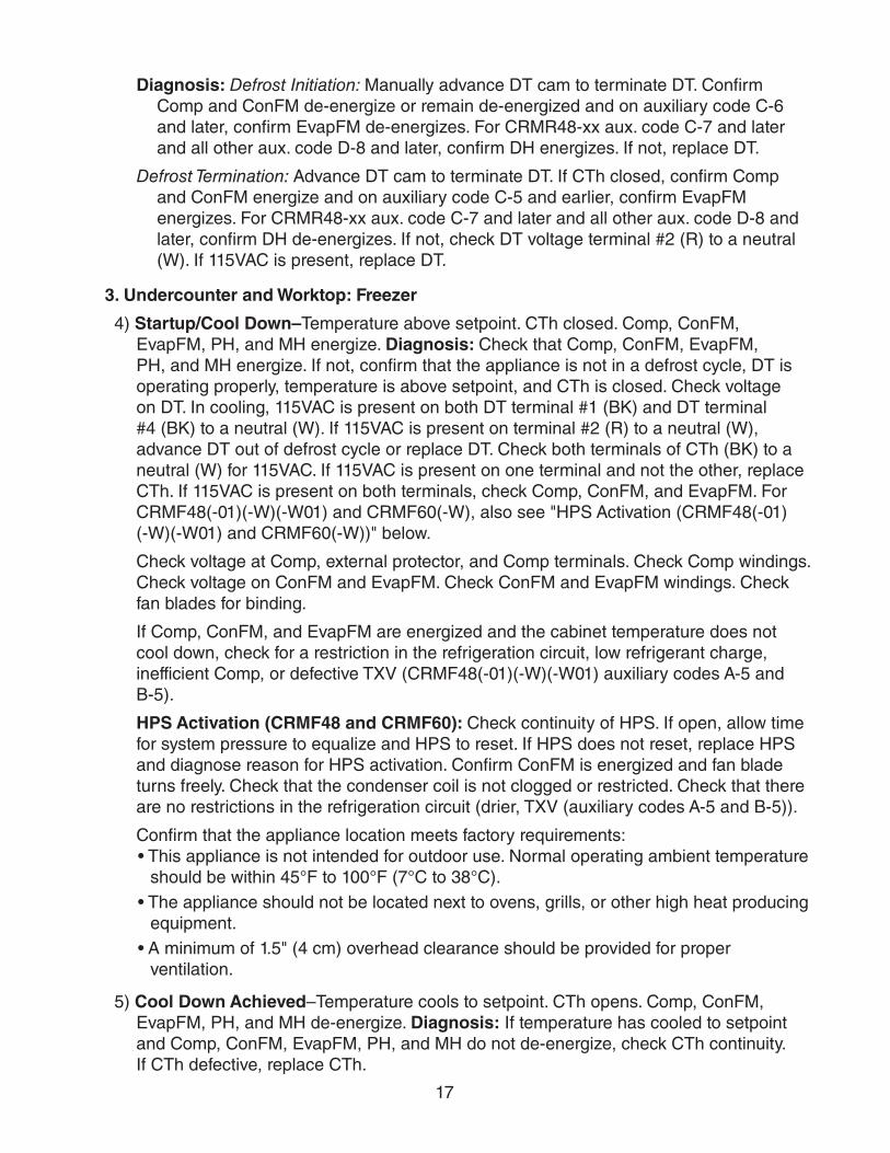
Diagnosis: Defrost Initiation: Manually advance DT cam to terminate DT. Confirm Comp and ConFM de-energize or remain de-energized and on auxiliary code C-6 and later, confirm EvapFM de-energizes. For CRMR48-xx aux. code C-7 and later and all other aux. code D-8 and later, confirm DH energizes. If not, replace DT.
Defrost Termination: Advance DT cam to terminate DT. If CTh closed, confirm Comp and ConFM energize and on auxiliary code C-5 and earlier, confirm EvapFM energizes. For CRMR48-xx aux. code C-7 and later and all other aux. code D-8 and later, confirm DH de-energizes. If not, check DT voltage terminal #2 (R) to a neutral (W). If 115VAC is present, replace DT.
3. Undercounter and Worktop: Freezer
4) Startup/Cool Down–Temperature above setpoint. CTh closed. Comp, ConFM, EvapFM, PH, and MH energize. Diagnosis: Check that Comp, ConFM, EvapFM, PH, and MH energize. If not, confirm that the appliance is not in a defrost cycle, DT is operating properly, temperature is above setpoint, and CTh is closed. Check voltage on DT. In cooling, 115VAC is present on both DT terminal #1 (BK) and DT terminal #4 (BK) to a neutral (W). If 115VAC is present on terminal #2 (R) to a neutral (W), advance DT out of defrost cycle or replace DT. Check both terminals of CTh (BK) to a neutral (W) for 115VAC. If 115VAC is present on one terminal and not the other, replace CTh. If 115VAC is present on both terminals, check Comp, ConFM, and EvapFM. For CRMF48(-01)(-W)(-W01) and CRMF60(-W), also see "HPS Activation (CRMF48(-01)(-W)(-W01) and CRMF60(-W))" below.
Check voltage at Comp, external protector, and Comp terminals. Check Comp windings. Check voltage on ConFM and EvapFM. Check ConFM and EvapFM windings. Check fan blades for binding.
If Comp, ConFM, and EvapFM are energized and the cabinet temperature does not cool down, check for a restriction in the refrigeration circuit, low refrigerant charge, inefficient Comp, or defective TXV (CRMF48(-01)(-W)(-W01) auxiliary codes A-5 and B-5).
HPS Activation (CRMF48 and CRMF60): Check continuity of HPS. If open, allow time for system pressure to equalize and HPS to reset. If HPS does not reset, replace HPS and diagnose reason for HPS activation. Confirm ConFM is energized and fan blade turns freely. Check that the condenser coil is not clogged or restricted. Check that there are no restrictions in the refrigeration circuit (drier, TXV (auxiliary codes A-5 and B-5)).
Confirm that the appliance location meets factory requirements: • This appliance is not intended for outdoor use. Normal operating ambient temperature
should be within 45°F to 100°F (7°C to 38°C). • The appliance should not be located next to ovens, grills, or other high heat producing
equipment.• A minimum of 1.5" (4 cm) overhead clearance should be provided for proper
ventilation.
5) Cool Down Achieved–Temperature cools to setpoint. CTh opens. Comp, ConFM, EvapFM, PH, and MH de-energize. Diagnosis: If temperature has cooled to setpoint and Comp, ConFM, EvapFM, PH, and MH do not de-energize, check CTh continuity. If CTh defective, replace CTh.
18
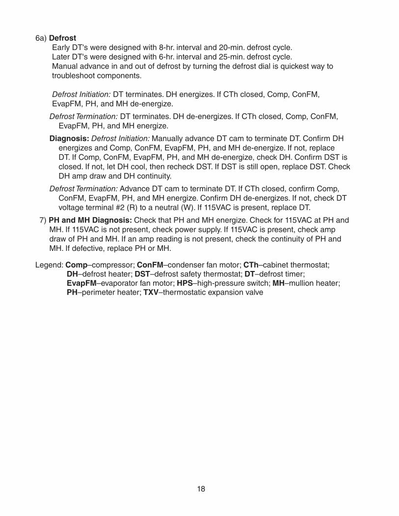
6a) DefrostEarly DT's were designed with 8-hr. interval and 20-min. defrost cycle. Later DT's were designed with 6-hr. interval and 25-min. defrost cycle. Manual advance in and out of defrost by turning the defrost dial is quickest way to troubleshoot components. Defrost Initiation: DT terminates. DH energizes. If CTh closed, Comp, ConFM, EvapFM, PH, and MH de-energize.
Defrost Termination: DT terminates. DH de-energizes. If CTh closed, Comp, ConFM, EvapFM, PH, and MH energize.
Diagnosis: Defrost Initiation: Manually advance DT cam to terminate DT. Confirm DH energizes and Comp, ConFM, EvapFM, PH, and MH de-energize. If not, replace DT. If Comp, ConFM, EvapFM, PH, and MH de-energize, check DH. Confirm DST is closed. If not, let DH cool, then recheck DST. If DST is still open, replace DST. Check DH amp draw and DH continuity.
Defrost Termination: Advance DT cam to terminate DT. If CTh closed, confirm Comp, ConFM, EvapFM, PH, and MH energize. Confirm DH de-energizes. If not, check DT voltage terminal #2 (R) to a neutral (W). If 115VAC is present, replace DT.
7) PH and MH Diagnosis: Check that PH and MH energize. Check for 115VAC at PH and MH. If 115VAC is not present, check power supply. If 115VAC is present, check amp draw of PH and MH. If an amp reading is not present, check the continuity of PH and MH. If defective, replace PH or MH.
Legend: Comp–compressor; ConFM–condenser fan motor; CTh–cabinet thermostat; DH–defrost heater; DST–defrost safety thermostat; DT–defrost timer; EvapFM–evaporator fan motor; HPS–high-pressure switch; MH–mullion heater; PH–perimeter heater; TXV–thermostatic expansion valve
19
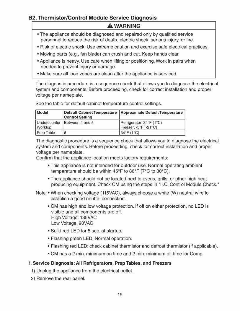
B2. Thermistor/Control Module Service Diagnosis
WARNING• The appliance should be diagnosed and repaired only by qualified service
personnel to reduce the risk of death, electric shock, serious injury, or fire.
• Risk of electric shock. Use extreme caution and exercise safe electrical practices.
• Moving parts (e.g., fan blade) can crush and cut. Keep hands clear.
• Appliance is heavy. Use care when lifting or positioning. Work in pairs when needed to prevent injury or damage.
• Make sure all food zones are clean after the appliance is serviced.
The diagnostic procedure is a sequence check that allows you to diagnose the electrical system and components. Before proceeding, check for correct installation and proper voltage per nameplate.
See the table for default cabinet temperature control settings.
Model Default Cabinet Temperature Control Setting
Approximate Default Temperature
UndercounterWorktop
Between 4 and 5 Refrigerator: 34°F (1°C) Freezer: -5°F (-21°C)
Prep Table 6 34°F (1°C)
The diagnostic procedure is a sequence check that allows you to diagnose the electrical system and components. Before proceeding, check for correct installation and proper voltage per nameplate. Confirm that the appliance location meets factory requirements:
• This appliance is not intended for outdoor use. Normal operating ambient temperature should be within 45°F to 86°F (7°C to 30°C).
• The appliance should not be located next to ovens, grills, or other high heat producing equipment. Check CM using the steps in "II.C. Control Module Check."
Note: • When checking voltage (115VAC), always choose a white (W) neutral wire to establish a good neutral connection.
• CM has high and low voltage protection. If off on either protection, no LED is visible and all components are off. High Voltage: 135VAC Low Voltage: 90VAC
• Solid red LED for 5 sec. at startup.
• Flashing green LED: Normal operation.
• Flashing red LED: check cabinet thermistor and defrost thermistor (if applicable).
• CM has a 2 min. minimum on time and 2 min. minimum off time for Comp.
1. Service Diagnosis: All Refrigerators, Prep Tables, and Freezers
1) Unplug the appliance from the electrical outlet.
2) Remove the rear panel.
20
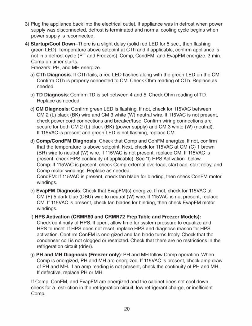
3) Plug the appliance back into the electrical outlet. If appliance was in defrost when power supply was disconnected, defrost is terminated and normal cooling cycle begins when power supply is reconnected.
4) Startup/Cool Down–There is a slight delay (solid red LED for 5 sec., then flashing green LED). Temperature above setpoint at CTh and if applicable, confirm appliance is not in a defrost cycle (PT and Freezers). Comp, CondFM, and EvapFM energize. 2-min. Comp on timer starts. Freezers: PH, and MH energize.a) CTh Diagnosis: If CTh fails, a red LED flashes along with the green LED on the CM.
Confirm CTh is properly connected to CM. Check Ohm reading of CTh. Replace as needed.
b) TD Diagnosis: Confirm TD is set between 4 and 5. Check Ohm reading of TD. Replace as needed.
c) CM Diagnosis: Confirm green LED is flashing. If not, check for 115VAC between CM 2 (L) black (BK) wire and CM 3 white (W) neutral wire. If 115VAC is not present, check power cord connections and breaker/fuse. Confirm wiring connections are secure for both CM 2 (L) black (BK) (power supply) and CM 3 white (W) (neutral). If 115VAC is present and green LED is not flashing, replace CM.
d) Comp/CondFM Diagnosis: Check that Comp and ConFM energize. If not, confirm that the temperature is above setpoint. Next, check for 115VAC at CM (C) 1 brown (BR) wire to neutral (W) wire. If 115VAC is not present, replace CM. If 115VAC is present, check HPS continuity (if applicable). See "f) HPS Activation" below. Comp: If 115VAC is present, check Comp external overload, start cap, start relay, and Comp motor windings. Replace as needed. CondFM: If 115VAC is present, check fan blade for binding, then check ConFM motor windings.
e) EvapFM Diagnosis: Check that EvapFM(s) energize. If not, check for 115VAC at CM (F) 5 dark blue (DBU) wire to neutral (W) wire. If 115VAC is not present, replace CM. If 115VAC is present, check fan blades for binding, then check EvapFM motor windings.
f) HPS Activation (CRMR60 and CRMR72 Prep Table and Freezer Models): Check continuity of HPS. If open, allow time for system pressure to equalize and HPS to reset. If HPS does not reset, replace HPS and diagnose reason for HPS activation. Confirm ConFM is energized and fan blade turns freely. Check that the condenser coil is not clogged or restricted. Check that there are no restrictions in the refrigeration circuit (drier).
g) PH and MH Diagnosis (Freezer only): PH and MH follow Comp operation. When Comp is energized, PH and MH are energized. If 115VAC is present, check amp draw of PH and MH. If an amp reading is not present, check the continuity of PH and MH. If defective, replace PH or MH.
If Comp, ConFM, and EvapFM are energized and the cabinet does not cool down, check for a restriction in the refrigeration circuit, low refrigerant charge, or inefficient Comp.
21
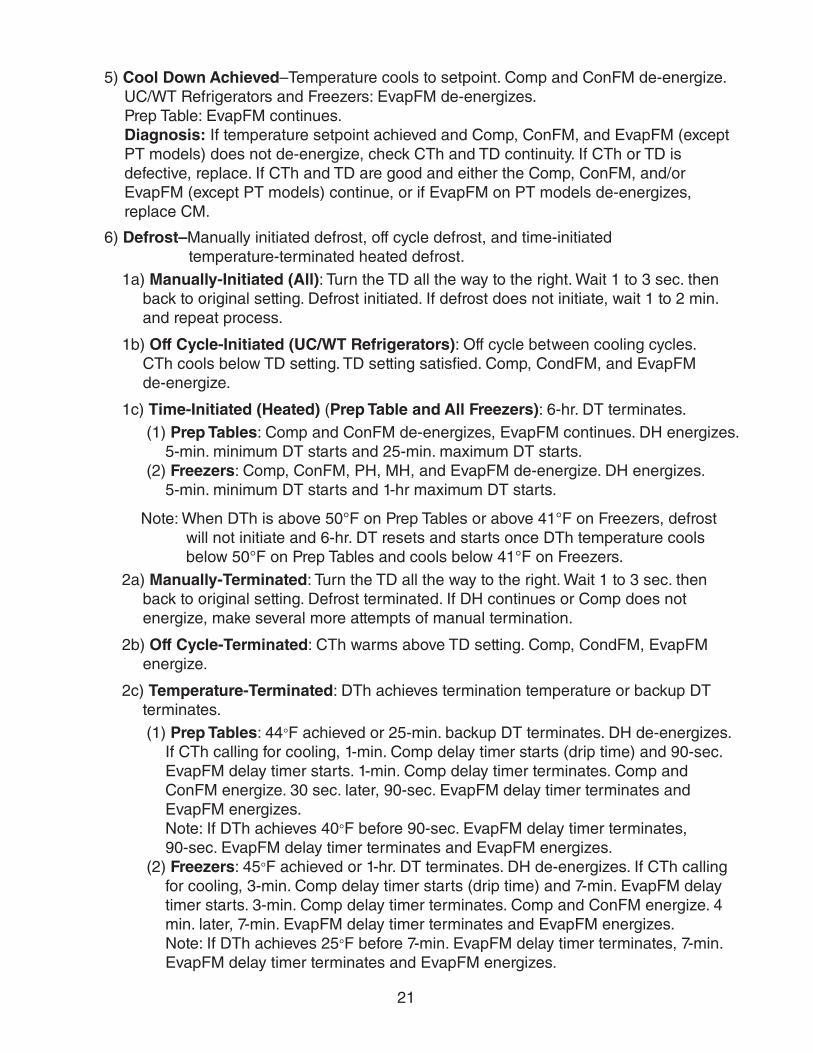
5) Cool Down Achieved–Temperature cools to setpoint. Comp and ConFM de-energize. UC/WT Refrigerators and Freezers: EvapFM de-energizes. Prep Table: EvapFM continues. Diagnosis: If temperature setpoint achieved and Comp, ConFM, and EvapFM (except PT models) does not de-energize, check CTh and TD continuity. If CTh or TD is defective, replace. If CTh and TD are good and either the Comp, ConFM, and/or EvapFM (except PT models) continue, or if EvapFM on PT models de-energizes, replace CM.
6) Defrost–Manually initiated defrost, off cycle defrost, and time-initiated temperature-terminated heated defrost.1a) Manually-Initiated (All): Turn the TD all the way to the right. Wait 1 to 3 sec. then
back to original setting. Defrost initiated. If defrost does not initiate, wait 1 to 2 min. and repeat process.
1b) Off Cycle-Initiated (UC/WT Refrigerators): Off cycle between cooling cycles. CTh cools below TD setting. TD setting satisfied. Comp, CondFM, and EvapFM de-energize.
1c) Time-Initiated (Heated) (Prep Table and All Freezers): 6-hr. DT terminates.(1) Prep Tables: Comp and ConFM de-energizes, EvapFM continues. DH energizes.
5-min. minimum DT starts and 25-min. maximum DT starts.(2) Freezers: Comp, ConFM, PH, MH, and EvapFM de-energize. DH energizes.
5-min. minimum DT starts and 1-hr maximum DT starts.
Note: When DTh is above 50°F on Prep Tables or above 41°F on Freezers, defrost will not initiate and 6-hr. DT resets and starts once DTh temperature cools below 50°F on Prep Tables and cools below 41°F on Freezers.
2a) Manually-Terminated: Turn the TD all the way to the right. Wait 1 to 3 sec. then back to original setting. Defrost terminated. If DH continues or Comp does not energize, make several more attempts of manual termination.
2b) Off Cycle-Terminated: CTh warms above TD setting. Comp, CondFM, EvapFM energize.
2c) Temperature-Terminated: DTh achieves termination temperature or backup DT terminates.(1) Prep Tables: 44°F achieved or 25-min. backup DT terminates. DH de-energizes.
If CTh calling for cooling, 1-min. Comp delay timer starts (drip time) and 90-sec. EvapFM delay timer starts. 1-min. Comp delay timer terminates. Comp and ConFM energize. 30 sec. later, 90-sec. EvapFM delay timer terminates and EvapFM energizes. Note: If DTh achieves 40°F before 90-sec. EvapFM delay timer terminates, 90-sec. EvapFM delay timer terminates and EvapFM energizes.
(2) Freezers: 45°F achieved or 1-hr. DT terminates. DH de-energizes. If CTh calling for cooling, 3-min. Comp delay timer starts (drip time) and 7-min. EvapFM delay timer starts. 3-min. Comp delay timer terminates. Comp and ConFM energize. 4 min. later, 7-min. EvapFM delay timer terminates and EvapFM energizes. Note: If DTh achieves 25°F before 7-min. EvapFM delay timer terminates, 7-min. EvapFM delay timer terminates and EvapFM energizes.
22
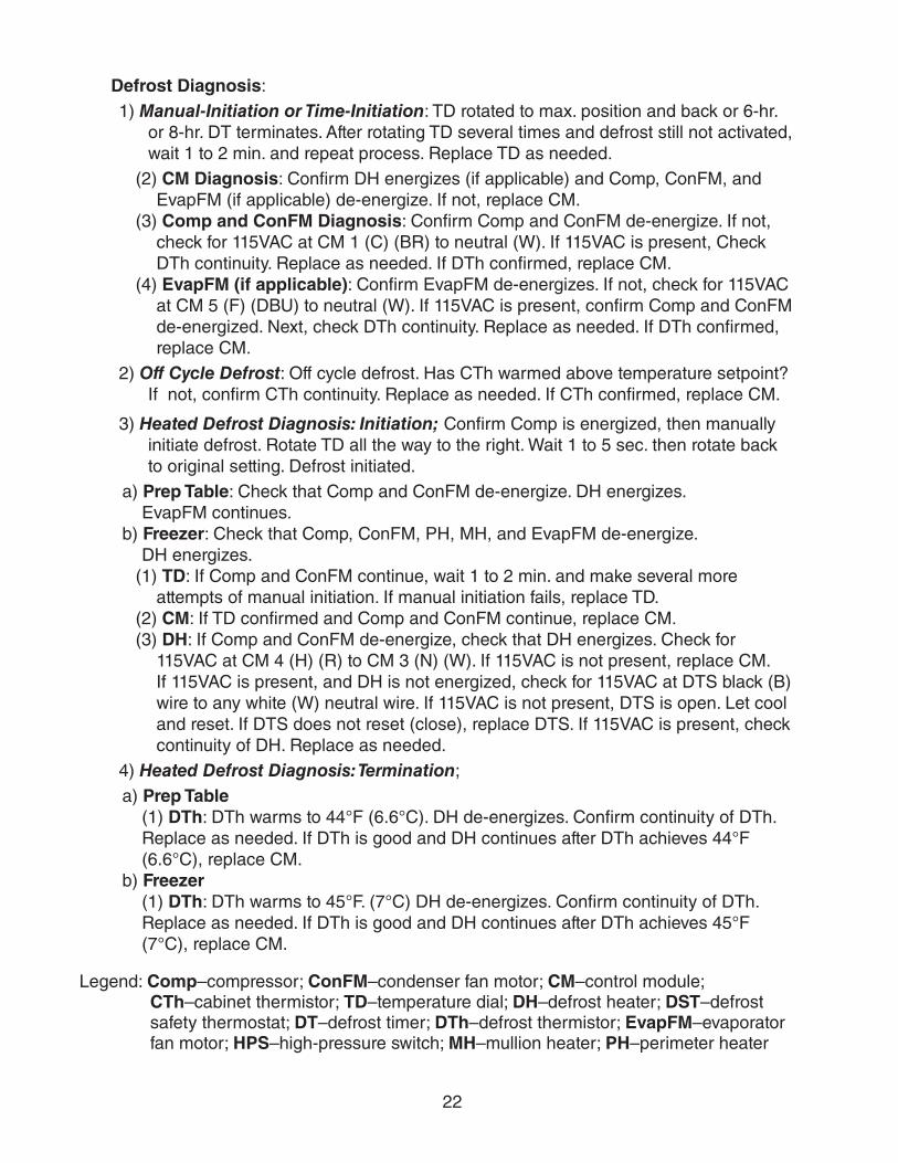
Defrost Diagnosis: 1) Manual-Initiation or Time-Initiation: TD rotated to max. position and back or 6-hr.
or 8-hr. DT terminates. After rotating TD several times and defrost still not activated, wait 1 to 2 min. and repeat process. Replace TD as needed.
(2) CM Diagnosis: Confirm DH energizes (if applicable) and Comp, ConFM, and EvapFM (if applicable) de-energize. If not, replace CM.
(3) Comp and ConFM Diagnosis: Confirm Comp and ConFM de-energize. If not, check for 115VAC at CM 1 (C) (BR) to neutral (W). If 115VAC is present, Check DTh continuity. Replace as needed. If DTh confirmed, replace CM.
(4) EvapFM (if applicable): Confirm EvapFM de-energizes. If not, check for 115VAC at CM 5 (F) (DBU) to neutral (W). If 115VAC is present, confirm Comp and ConFM de-energized. Next, check DTh continuity. Replace as needed. If DTh confirmed, replace CM.
2) Off Cycle Defrost: Off cycle defrost. Has CTh warmed above temperature setpoint? If not, confirm CTh continuity. Replace as needed. If CTh confirmed, replace CM.
3) Heated Defrost Diagnosis: Initiation; Confirm Comp is energized, then manually initiate defrost. Rotate TD all the way to the right. Wait 1 to 5 sec. then rotate back to original setting. Defrost initiated.
a) Prep Table: Check that Comp and ConFM de-energize. DH energizes. EvapFM continues.
b) Freezer: Check that Comp, ConFM, PH, MH, and EvapFM de-energize. DH energizes.
(1) TD: If Comp and ConFM continue, wait 1 to 2 min. and make several more attempts of manual initiation. If manual initiation fails, replace TD.
(2) CM: If TD confirmed and Comp and ConFM continue, replace CM.(3) DH: If Comp and ConFM de-energize, check that DH energizes. Check for
115VAC at CM 4 (H) (R) to CM 3 (N) (W). If 115VAC is not present, replace CM. If 115VAC is present, and DH is not energized, check for 115VAC at DTS black (B) wire to any white (W) neutral wire. If 115VAC is not present, DTS is open. Let cool and reset. If DTS does not reset (close), replace DTS. If 115VAC is present, check continuity of DH. Replace as needed.
4) Heated Defrost Diagnosis: Termination; a) Prep Table
(1) DTh: DTh warms to 44°F (6.6°C). DH de-energizes. Confirm continuity of DTh. Replace as needed. If DTh is good and DH continues after DTh achieves 44°F (6.6°C), replace CM.
b) Freezer (1) DTh: DTh warms to 45°F. (7°C) DH de-energizes. Confirm continuity of DTh. Replace as needed. If DTh is good and DH continues after DTh achieves 45°F (7°C), replace CM.
Legend: Comp–compressor; ConFM–condenser fan motor; CM–control module; CTh–cabinet thermistor; TD–temperature dial; DH–defrost heater; DST–defrost safety thermostat; DT–defrost timer; DTh–defrost thermistor; EvapFM–evaporator fan motor; HPS–high-pressure switch; MH–mullion heater; PH–perimeter heater
23
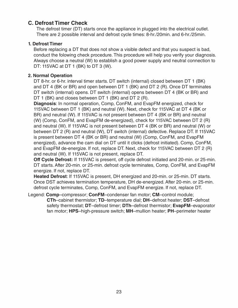
C. Defrost Timer CheckThe defrost timer (DT) starts once the appliance in plugged into the electrical outlet. There are 2 possible interval and defrost cycle times: 8-hr./20min. and 6-hr./25min.
1. Defrost TimerBefore replacing a DT that does not show a visible defect and that you suspect is bad, conduct the folowing check procedure. This procedure will help you verify your diagnosis. Always choose a neutral (W) to establish a good power supply and neutral connection to DT: 115VAC at DT 1 (BK) to DT 3 (W).
2. Normal OperationDT 8-hr. or 6-hr. interval timer starts. DT switch (internal) closed between DT 1 (BK) and DT 4 (BK or BR) and open between DT 1 (BK) and DT 2 (R). Once DT terminates DT switch (internal) opens. DT switch (internal) opens between DT 4 (BK or BR) and DT 1 (BK) and closes between DT 1 (BK) and DT 2 (R). Diagnosis: In normal operation, Comp, ConFM, and EvapFM energized, check for 115VAC between DT 1 (BK) and neutral (W). Next, check for 115VAC at DT 4 (BK or BR) and neutral (W). If 115VAC is not present between DT 4 (BK or BR) and neutral (W) (Comp, ConFM, and EvapFM de-energized), check for 115VAC between DT 2 (R) and neutral (W). If 115VAC is not present between DT 4 (BK or BR) and neutral (W) or between DT 2 (R) and neutral (W), DT switch (internal) defective. Replace DT. If 115VAC is present between DT 4 (BK or BR) and neutral (W) (Comp, ConFM, and EvapFM energized), advance the cam dial on DT until it clicks (defrost initiated). Comp, ConFM, and EvapFM de-energize. If not, replace DT. Next, check for 115VAC between DT 2 (R) and neutral (W). If 115VAC is not present, replace DT. Off Cycle Defrost: If 115VAC is present, off cycle defrost initiated and 20-min. or 25-min. DT starts. After 20-min. or 25-min. defrost cycle terminates, Comp, ConFM, and EvapFM energize. If not, replace DT. Heated Defrost: If 115VAC is present, DH energized and 20-min. or 25-min. DT starts. Once DST achieves termination temperature, DH de-energized. After 20-min. or 25-min. defrost cycle terminates, Comp, ConFM, and EvapFM energize. If not, replace DT.
Legend: Comp–compressor; ConFM–condenser fan motor; CM–control module; CTh–cabinet thermistor; TD–temperature dial; DH–defrost heater; DST–defrost safety thermostat; DT–defrost timer; DTh–defrost thermistor; EvapFM–evaporator fan motor; HPS–high-pressure switch; MH–mullion heater; PH–perimeter heater
24
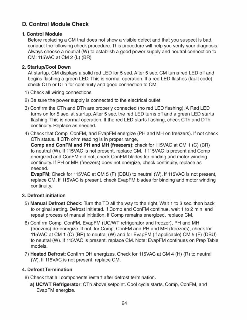
D. Control Module Check
1. Control ModuleBefore replacing a CM that does not show a visible defect and that you suspect is bad, conduct the following check procedure. This procedure will help you verify your diagnosis. Always choose a neutral (W) to establish a good power supply and neutral connection to CM: 115VAC at CM 2 (L) (BR)
2. Startup/Cool DownAt startup, CM displays a solid red LED for 5 sed. After 5 sec. CM turns red LED off and begins flashing a green LED. This is normal operation. If a red LED flashes (fault code), check CTh or DTh for continuity and good connection to CM.
1) Check all wiring connections.
2) Be sure the power supply is connected to the electrical outlet.
3) Confirm the CTh and DTh are properly connected (no red LED flashing). A Red LED turns on for 5 sec. at startup. After 5 sec. the red LED turns off and a green LED starts flashing. This is normal operation. If the red LED starts flashing, check CTh and DTh continuity. Replace as needed.
4) Check that Comp, ConFM, and EvapFM energize (PH and MH on freezers). If not check CTh status. If CTh ohm reading is in proper range, Comp and ConFM and PH and MH (freezers); check for 115VAC at CM 1 (C) (BR) to neutral (W). If 115VAC is not present, replace CM. If 115VAC is present and Comp energized and ConFM did not, check ConFM blades for binding and motor winding continuity. If PH or MH (freezers) does not energize, check continuity, replace as needed. EvapFM; Check for 115VAC at CM 5 (F) (DBU) to neutral (W). If 115VAC is not present, replace CM. If 115VAC is present, check EvapFM blades for binding and motor winding continuity.
3. Defrost initiation
5) Manual Defrost Check: Turn the TD all the way to the right. Wait 1 to 3 sec. then back to original setting. Defrost initiated. If Comp and ConFM continue, wait 1 to 2 min. and repeat process of manual initiation. If Comp remains energized, replace CM.
6) Confirm Comp, ConFM, EvapFM (UC/WT refrigerator and freezer), PH and MH (freezers) de-energize. If not, for Comp, ConFM and PH and MH (freezers), check for 115VAC at CM 1 (C) (BR) to neutral (W) and for EvapFM (if applicable) CM 5 (F) (DBU) to neutral (W). If 115VAC is present, replace CM. Note: EvapFM continues on Prep Table models.
7) Heated Defrost: Confirm DH energizes. Check for 115VAC at CM 4 (H) (R) to neutral (W). If 115VAC is not present, replace CM.
4. Defrost Termination
8) Check that all components restart after defrost termination.a) UC/WT Refrigerator: CTh above setpoint. Cool cycle starts. Comp, ConFM, and
EvapFM energize.
25
b) Prep Table: DTh warms to 44°F (6.6°C). DH de-energizes. Confirm continuity of DTh. Replace as needed. If DTh is good and DH continues after DTh achieves 44°F (6.6°C), replace CM.
c) Freezer: DTh warms to 45°F (7°C) or 50°F (10°C). DH de-energizes. Confirm continuity of DTh. Replace as needed. If DTh is good and DH continues after DTh achieves 45°F (7°C) or 50°F (10°C), replace CM.
Legend: Comp–compressor; ConFM–condenser fan motor; CM–control module; CTh–cabinet thermistor; DH–defrost heater; DTh–defrost thermistor; EvapFM–evaporator fan motors, MH–mullion heater; PH–perimeter heater
26
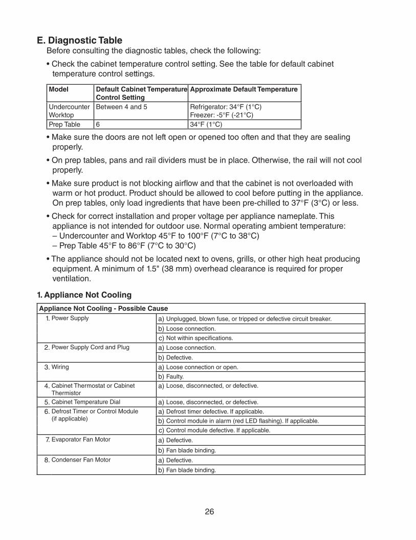
E. Diagnostic TableBefore consulting the diagnostic tables, check the following:
• Check the cabinet temperature control setting. See the table for default cabinet temperature control settings.
Model Default Cabinet Temperature Control Setting
Approximate Default Temperature
UndercounterWorktop
Between 4 and 5 Refrigerator: 34°F (1°C) Freezer: -5°F (-21°C)
Prep Table 6 34°F (1°C)
• Make sure the doors are not left open or opened too often and that they are sealing properly.
• On prep tables, pans and rail dividers must be in place. Otherwise, the rail will not cool properly.
• Make sure product is not blocking airflow and that the cabinet is not overloaded with warm or hot product. Product should be allowed to cool before putting in the appliance. On prep tables, only load ingredients that have been pre-chilled to 37°F (3°C) or less.
• Check for correct installation and proper voltage per appliance nameplate. This appliance is not intended for outdoor use. Normal operating ambient temperature: – Undercounter and Worktop 45°F to 100°F (7°C to 38°C) – Prep Table 45°F to 86°F (7°C to 30°C)
• The appliance should not be located next to ovens, grills, or other high heat producing equipment. A minimum of 1.5" (38 mm) overhead clearance is required for proper ventilation.
1. Appliance Not Cooling
Appliance Not Cooling - Possible Cause1. Power Supply a) Unplugged, blown fuse, or tripped or defective circuit breaker.
b) Loose connection.
c) Not within specifications.
2. Power Supply Cord and Plug a) Loose connection.
b) Defective.
3. Wiring a) Loose connection or open.
b) Faulty.
4. Cabinet Thermostat or Cabinet Thermistor
a) Loose, disconnected, or defective.
5. Cabinet Temperature Dial a) Loose, disconnected, or defective.
6. Defrost Timer or Control Module (if applicable)
a) Defrost timer defective. If applicable.
b) Control module in alarm (red LED flashing). If applicable.
c) Control module defective. If applicable.
7. Evaporator Fan Motor a) Defective.
b) Fan blade binding.
8. Condenser Fan Motor a) Defective.
b) Fan blade binding.
27
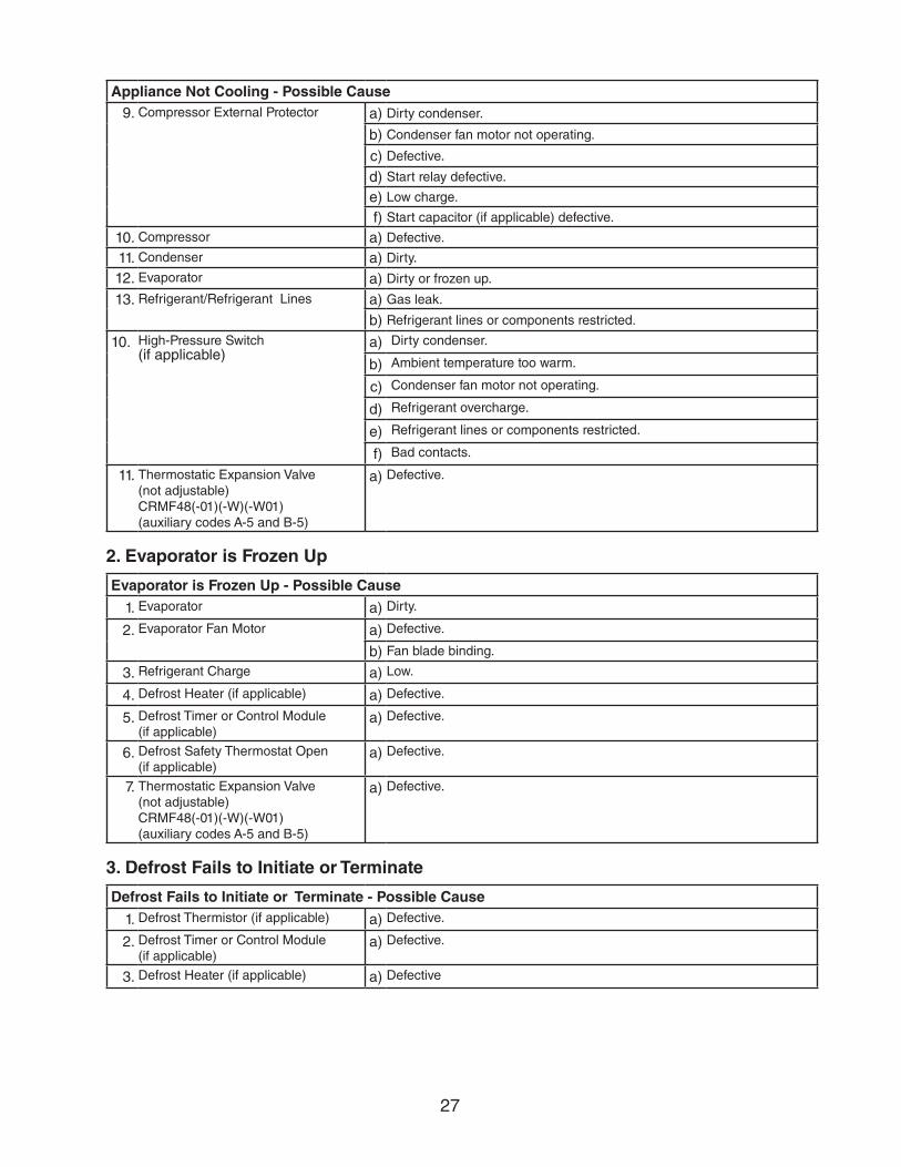
Appliance Not Cooling - Possible Cause9. Compressor External Protector a) Dirty condenser.
b) Condenser fan motor not operating.
c) Defective.
d) Start relay defective.
e) Low charge.
f) Start capacitor (if applicable) defective.
10. Compressor a) Defective.
11. Condenser a) Dirty.
12. Evaporator a) Dirty or frozen up.
13. Refrigerant/Refrigerant Lines a) Gas leak.
b) Refrigerant lines or components restricted.
10. High-Pressure Switch (if applicable)
a) Dirty condenser.
b) Ambient temperature too warm.
c) Condenser fan motor not operating.
d) Refrigerant overcharge.
e) Refrigerant lines or components restricted.
f) Bad contacts.
11. Thermostatic Expansion Valve (not adjustable) CRMF48(-01)(-W)(-W01)(auxiliary codes A-5 and B-5)
a) Defective.
2. Evaporator is Frozen Up
Evaporator is Frozen Up - Possible Cause
1. Evaporator a) Dirty.
2. Evaporator Fan Motor a) Defective.
b) Fan blade binding.
3. Refrigerant Charge a) Low.
4. Defrost Heater (if applicable) a) Defective.
5. Defrost Timer or Control Module (if applicable)
a) Defective.
6. Defrost Safety Thermostat Open (if applicable)
a) Defective.
7. Thermostatic Expansion Valve (not adjustable) CRMF48(-01)(-W)(-W01)(auxiliary codes A-5 and B-5)
a) Defective.
3. Defrost Fails to Initiate or Terminate
Defrost Fails to Initiate or Terminate - Possible Cause
1. Defrost Thermistor (if applicable) a) Defective.
2. Defrost Timer or Control Module (if applicable)
a) Defective.
3. Defrost Heater (if applicable) a) Defective
28
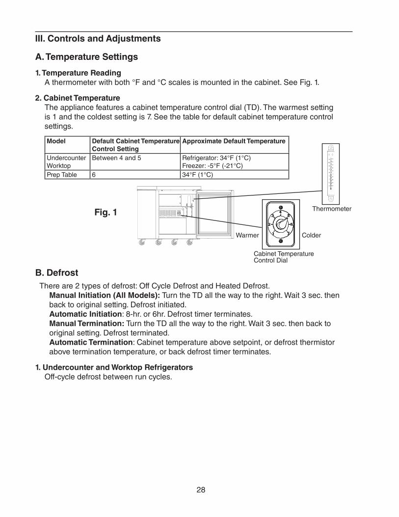
B. DefrostThere are 2 types of defrost: Off Cycle Defrost and Heated Defrost.
Manual Initiation (All Models): Turn the TD all the way to the right. Wait 3 sec. then back to original setting. Defrost initiated. Automatic Initiation: 8-hr. or 6hr. Defrost timer terminates. Manual Termination: Turn the TD all the way to the right. Wait 3 sec. then back to original setting. Defrost terminated. Automatic Termination: Cabinet temperature above setpoint, or defrost thermistor above termination temperature, or back defrost timer terminates.
1. Undercounter and Worktop RefrigeratorsOff-cycle defrost between run cycles.
III. Controls and Adjustments
A. Temperature Settings
1. Temperature ReadingA thermometer with both °F and °C scales is mounted in the cabinet. See Fig. 1.
2. Cabinet TemperatureThe appliance features a cabinet temperature control dial (TD). The warmest setting is 1 and the coldest setting is 7. See the table for default cabinet temperature control settings.
Model Default Cabinet Temperature Control Setting
Approximate Default Temperature
UndercounterWorktop
Between 4 and 5 Refrigerator: 34°F (1°C) Freezer: -5°F (-21°C)
Prep Table 6 34°F (1°C)
Fig. 1 Thermometer
Cabinet Temperature Control Dial
Warmer Colder
29
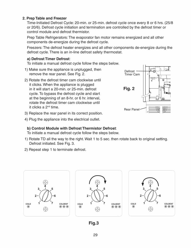
2. Prep Table and Freezer Time-Initiated Defrost Cycle: 20-min. or 25-min. defrost cycle once every 8 or 6 hrs. (25/8 or 20/6). Defrost cycle initiation and termination are controlled by the defrost timer or control module and defrost thermistor.
Prep Table Refrigerators: The evaporator fan motor remains energized and all other components de-energize during the defrost cycle.
Freezers: The defrost heater energizes and all other components de-energize during the defrost cycle. There is an in-line defrost safety thermostat.
a) Defrost Timer Defrost: To initiate a manual defrost cycle follow the steps below.
1) Make sure the appliance is unplugged, then remove the rear panel. See Fig. 2.
2) Rotate the defrost timer cam clockwise until it clicks. When the appliance is plugged in it will start a 20-min. or 25-min. defrost cycle. To bypass the defrost cycle and start at the beginning of an 8-hr. or 6 hr. interval, rotate the defrost timer cam clockwise until it clicks a 2nd time.
3) Replace the rear panel in its correct position.
4) Plug the appliance into the electrical outlet.
b) Control Module with Defrost Thermistor Defrost:To initiate a manual defrost cycle follow the steps below.
1) Rotate TD all the way to the right. Wait 1 to 5 sec. then rotate back to original setting. Defrost initiated. See Fig. 3.
2) Repeat step 1 to terminate defrost.
Rear Panel
Defrost Timer Cam
Fig. 2
Fig.3
30
C. Safety Devices
1. Compressor External or Internal Protector (All Models)If combined temperature/amperage value is above the limit specified by the compressor manufacturer, the compressor protector operates independently to turn off the compressor. The compressor protector de-energizes the compressor until the temperature/amperage value returns to an acceptable level.
2. High-Pressure Switch If pressure on the high-side of the appliance exceeds Hoshizaki specifications, the high-pressure switch activates and interrupts the compressor circuit, de-energizing the compressor until the pressure returns to an acceptable level.If the condenser fan motor is operating and the compressor is off, it is most likely that the compressor protector opened. If both the compressor and condenser fan motor are off, it is most likely the appliance is off or the high-pressure switch has opened.
D. Perimeter and Mullion HeatersFreezers are equipped with perimeter and mullion heaters. If condensation occurs, check continuity of heaters.
31
IV. Refrigeration Circuit and Component Service Information
WARNING• This appliance should be diagnosed and repaired only by qualified service
personnel to reduce the risk of death, electric shock, serious injury, or fire.
• To reduce the risk of electric shock, do not touch the plug with damp hands.
• Unplug the appliance from the electrical outlet before servicing.
• Make sure all food zones in the appliance are clean after the appliance is serviced.
A. Refrigeration Circuit Service Information
WARNING• Repairs requiring the refrigeration circuit to be opened must be performed by
properly trained and EPA-certified service personnel.
• Use an electronic leak detector or soap bubbles to check for leaks. Add a trace of refrigerant to the system (if using an electronic leak detector), and then raise the pressure using nitrogen gas (140 PSIG). Do not use R-134a as a mixture with pressurized air for leak testing.
NOTICE• Always recover the refrigerant and store it in an approved container. Do not
discharge the refrigerant into the atmosphere.
• Do not leave the system open for longer than 15 minutes when replacing or servicing parts. The Polyol Ester (POE) oils used in R-134a appliances can absorb moisture quickly. Therefore it is important to prevent moisture from entering the system when replacing or servicing parts.
• Always install a new drier every time the sealed refrigeration system is opened. Do not replace the drier until after all other repair or replacement has been made. Install the new drier with the arrow on the drier in the direction of the refrigerant flow.
• When brazing, protect the drier by using a wet cloth to prevent the drier from overheating. Do not allow the drier to exceed 250°F (121°C).
1. Refrigerant RecoveryNo refrigerant access valves are provided on this appliance. Using proper refrigerantpractices, utilize a temporary tap-line valve on the high side to recover the refrigerant.Store the refrigerant in an approved container. Do not discharge the refrigerant into theatmosphere.After recovery is complete, replace the tap-line valve with a proper, permanent accessvalve.
32
2. Brazing
WARNING• R-134a itself is not flammable at atmospheric pressure and temperatures up to
212°F (100°C).
• R-134a itself is not explosive or poisonous. However, when exposed to high temperatures (open flames), R-134a can be decomposed to form hydrofluoric acid and carbonyl fluoride both of which are hazardous.
• Do not use silver alloy or copper alloy containing arsenic.
• Use an electronic leak detector or soap bubbles to check for leaks. Add a trace of refrigerant to the system (if using an electronic leak detector), and then raise the pressure using nitrogen gas (140 PSIG). Do not use R-134a as a mixture with pressurized air for leak testing.
1) Braze all fittings while purging with nitrogen gas flowing at a pressure of 3 to 4 PSIG.
NOTICE• Always install a new drier every time the sealed refrigeration system is opened.
Do not replace the drier until after all other repair or replacement has been made. Install the new drier with the arrow on the drier in the direction of the refrigerant flow.
• When brazing, protect the drier by using a wet cloth to prevent the drier from overheating. Do not allow the drier to exceed 250°F (121°C).
2) Use an electronic leak detector or soap bubbles to check for leaks. Add a trace of refrigerant to the system (if using an electronic leak detector), and then raise the pressure using nitrogen gas (140 PSIG). Do not use R-134a as a mixture with pressurized air for leak testing.
3. Evacuation and Recharge (R-134a)
1) Attach a vacuum pump to the system. Be sure the high-side charging hose is connected to the field-installed high-side access valve.
IMPORTANTThe vacuum level and vacuum pump may be the same as those for current refrigerants. However, the rubber hose and gauge manifold to be used for evacuation and refrigerant charge should be exclusively for POE oils.
2) Turn on the vacuum pump, then open the high-side valve on the gauge manifold. Never allow the oil in the vacuum pump to flow backwards.
3) Allow the vacuum pump to pull down to a 29.9" Hg vacuum. Evacuating period depends on pump capacity.
4) Close the high-side valve on the gauge manifold.
33
5) Disconnect the gauge manifold hose from the vacuum pump and attach it to a refrigerant service cylinder. Remember to loosen the connection and purge the air from the hose. See the nameplate for the required refrigerant charge. Hoshizaki recommends only virgin refrigerant or reclaimed refrigerant which meets the requirements of ARI Standard 700 (latest edition) be used.
6) A liquid charge is recommended when charging an R-134a system. Place the service cylinder on the scales; if the service cylinder is not equipped with a dip tube, invert the service cylinder, then place it on the scales. Open the high-side valve on the gauge manifold.
7) Allow the system to charge with liquid until the proper charge weight is met.
8) Close the high-side valve on the gauge manifold, then close the refrigerant access valve (if applicable). Disconnect the gauge manifold hose.
9) Cap the access valve to prevent a possible leak.
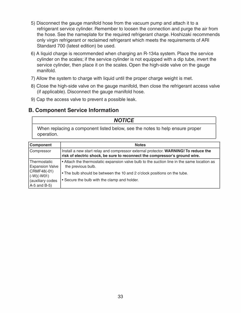
B. Component Service Information
NOTICEWhen replacing a component listed below, see the notes to help ensure proper operation.
Component Notes
Compressor Install a new start relay and compressor external protector. WARNING! To reduce the risk of electric shock, be sure to reconnect the compressor's ground wire.
ThermostaticExpansion ValveCRMF48(-01)(-W)(-W01) (auxiliary codes A-5 and B-5)
• Attach the thermostatic expansion valve bulb to the suction line in the same location as the previous bulb.
• The bulb should be between the 10 and 2 o'clock positions on the tube.
• Secure the bulb with the clamp and holder.
34
Fig. 6
Fig. 5
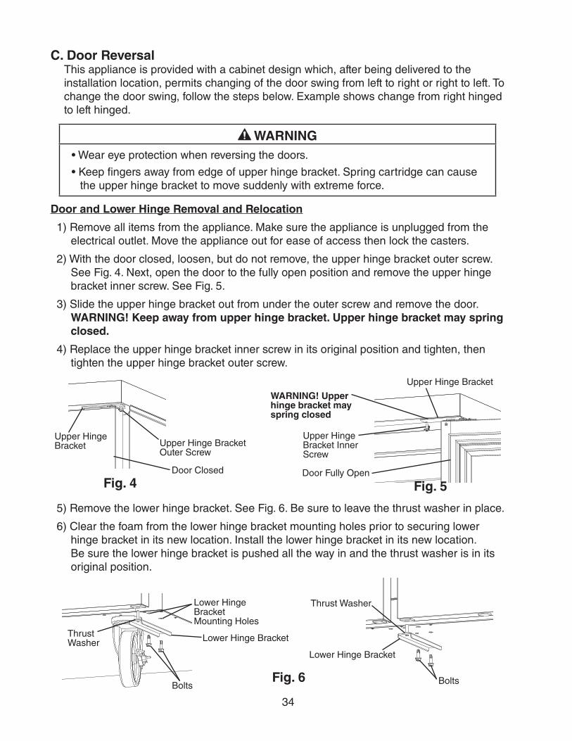
C. Door ReversalThis appliance is provided with a cabinet design which, after being delivered to the installation location, permits changing of the door swing from left to right or right to left. To change the door swing, follow the steps below. Example shows change from right hinged to left hinged.
WARNING• Wear eye protection when reversing the doors.
• Keep fingers away from edge of upper hinge bracket. Spring cartridge can cause the upper hinge bracket to move suddenly with extreme force.
Door and Lower Hinge Removal and Relocation
1) Remove all items from the appliance. Make sure the appliance is unplugged from the electrical outlet. Move the appliance out for ease of access then lock the casters.
2) With the door closed, loosen, but do not remove, the upper hinge bracket outer screw. See Fig. 4. Next, open the door to the fully open position and remove the upper hinge bracket inner screw. See Fig. 5.
3) Slide the upper hinge bracket out from under the outer screw and remove the door. WARNING! Keep away from upper hinge bracket. Upper hinge bracket may spring closed.
4) Replace the upper hinge bracket inner screw in its original position and tighten, then tighten the upper hinge bracket outer screw.
5) Remove the lower hinge bracket. See Fig. 6. Be sure to leave the thrust washer in place.
6) Clear the foam from the lower hinge bracket mounting holes prior to securing lower hinge bracket in its new location. Install the lower hinge bracket in its new location. Be sure the lower hinge bracket is pushed all the way in and the thrust washer is in its original position.
Lower Hinge Bracket
Bolts
Thrust Washer
Lower Hinge Bracket
Bolts
Thrust WasherLower Hinge Bracket Mounting Holes
Upper Hinge Bracket Inner Screw
Door Fully Open
WARNING! Upper hinge bracket may spring closed
Upper Hinge Bracket
Fig. 4
Upper Hinge Bracket Outer Screw
Door Closed
Upper Hinge Bracket
35
Fig. 7
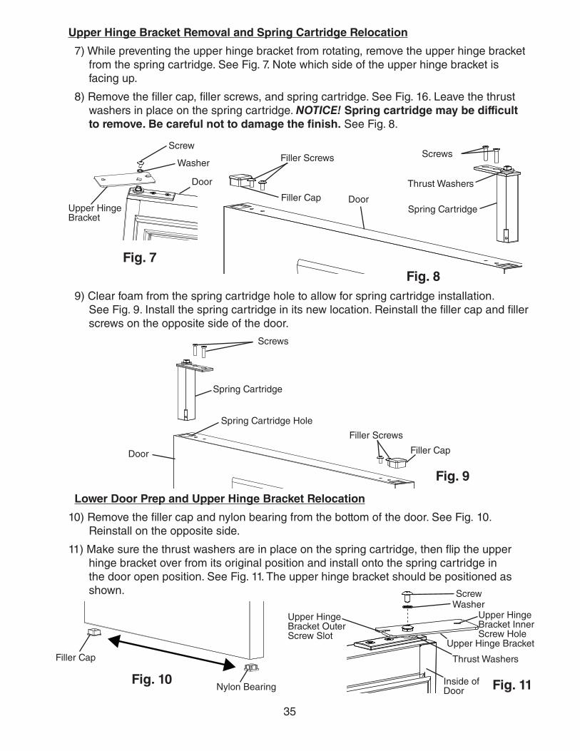
Upper Hinge Bracket Removal and Spring Cartridge Relocation
7) While preventing the upper hinge bracket from rotating, remove the upper hinge bracket from the spring cartridge. See Fig. 7. Note which side of the upper hinge bracket is facing up.
8) Remove the filler cap, filler screws, and spring cartridge. See Fig. 16. Leave the thrust washers in place on the spring cartridge. NOTICE! Spring cartridge may be difficult to remove. Be careful not to damage the finish. See Fig. 8.
Fig. 89) Clear foam from the spring cartridge hole to allow for spring cartridge installation.
See Fig. 9. Install the spring cartridge in its new location. Reinstall the filler cap and filler screws on the opposite side of the door.
Upper Hinge Bracket
Door
Screw
Washer
Filler Cap DoorSpring Cartridge
Filler Screws
Thrust Washers
Screws
Filler Screws
Filler CapDoor
Spring Cartridge
Screws
Fig. 9
Spring Cartridge Hole
Lower Door Prep and Upper Hinge Bracket Relocation
10) Remove the filler cap and nylon bearing from the bottom of the door. See Fig. 10. Reinstall on the opposite side.
11) Make sure the thrust washers are in place on the spring cartridge, then flip the upper hinge bracket over from its original position and install onto the spring cartridge in the door open position. See Fig. 11. The upper hinge bracket should be positioned as shown.
Upper Hinge Bracket
Inside of Door
ScrewWasher
Fig. 10 Fig. 11
Filler Cap
Nylon Bearing
Thrust Washers
Upper Hinge Bracket Inner Screw Hole
Upper Hinge Bracket Outer Screw Slot
36
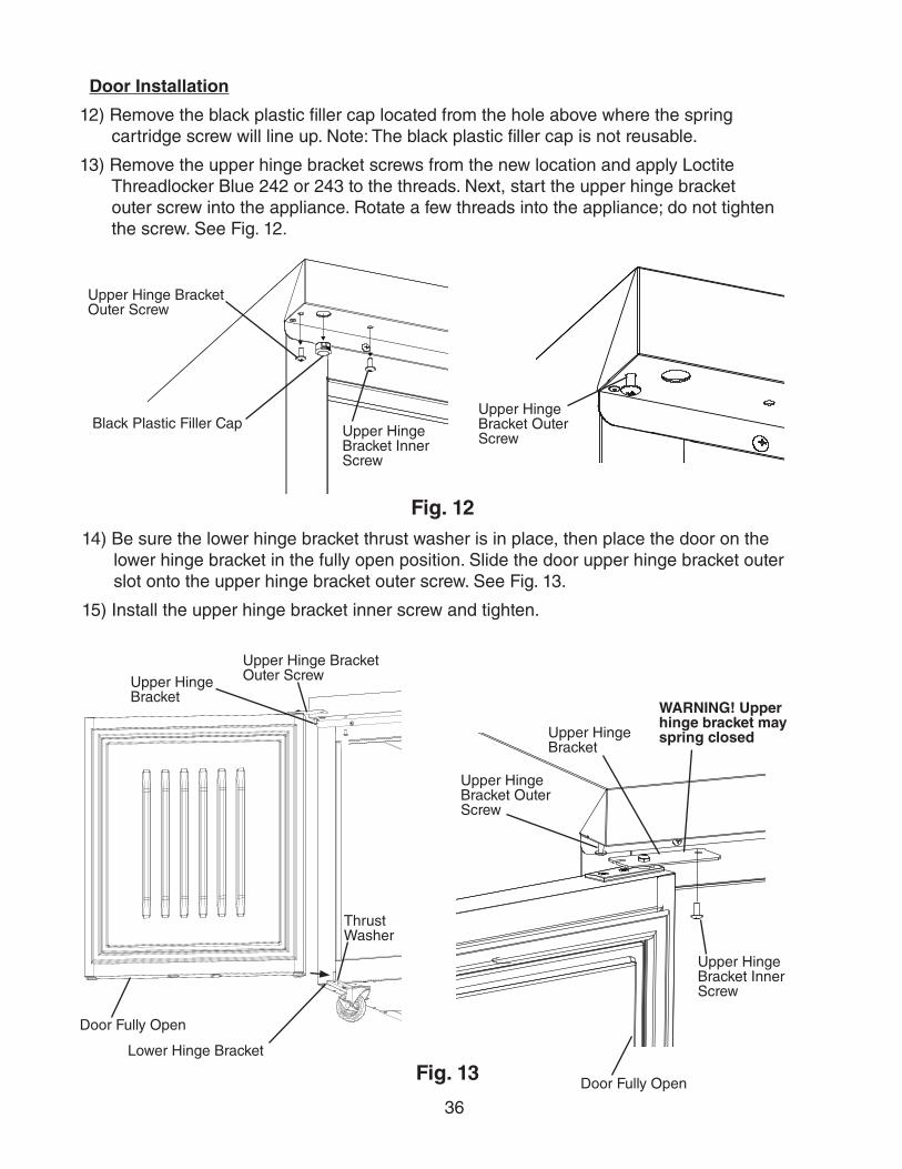
14) Be sure the lower hinge bracket thrust washer is in place, then place the door on the lower hinge bracket in the fully open position. Slide the door upper hinge bracket outer slot onto the upper hinge bracket outer screw. See Fig. 13.
15) Install the upper hinge bracket inner screw and tighten.
Fig. 12
Door Installation
12) Remove the black plastic filler cap located from the hole above where the spring cartridge screw will line up. Note: The black plastic filler cap is not reusable.
13) Remove the upper hinge bracket screws from the new location and apply Loctite Threadlocker Blue 242 or 243 to the threads. Next, start the upper hinge bracket outer screw into the appliance. Rotate a few threads into the appliance; do not tighten the screw. See Fig. 12.
Fig. 13
Door Fully Open
Lower Hinge Bracket
Upper Hinge Bracket Outer Screw
Upper Hinge Bracket Outer Screw
Door Fully Open
Upper Hinge Bracket
Upper Hinge Bracket Inner Screw
Upper Hinge Bracket
WARNING! Upper hinge bracket may spring closed
Thrust Washer
Upper Hinge Bracket Outer Screw
Upper Hinge Bracket Inner Screw
Black Plastic Filler CapUpper Hinge Bracket Outer Screw
37
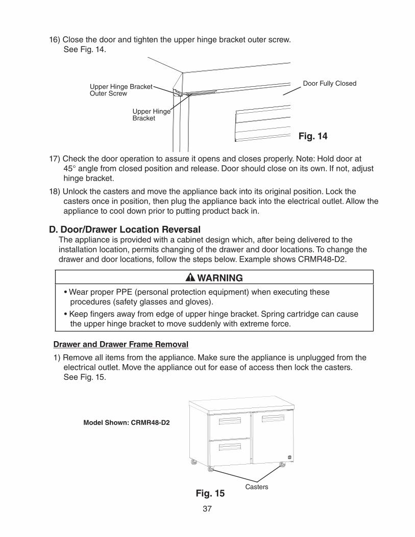
16) Close the door and tighten the upper hinge bracket outer screw. See Fig. 14.
Fig. 14
Upper Hinge Bracket
Upper Hinge Bracket Outer Screw
Door Fully Closed
17) Check the door operation to assure it opens and closes properly. Note: Hold door at 45° angle from closed position and release. Door should close on its own. If not, adjust hinge bracket.
18) Unlock the casters and move the appliance back into its original position. Lock the casters once in position, then plug the appliance back into the electrical outlet. Allow the appliance to cool down prior to putting product back in.
D. Door/Drawer Location ReversalThe appliance is provided with a cabinet design which, after being delivered to the installation location, permits changing of the drawer and door locations. To change the drawer and door locations, follow the steps below. Example shows CRMR48-D2.
WARNING• Wear proper PPE (personal protection equipment) when executing these
procedures (safety glasses and gloves).
• Keep fingers away from edge of upper hinge bracket. Spring cartridge can cause the upper hinge bracket to move suddenly with extreme force.
Drawer and Drawer Frame Removal
1) Remove all items from the appliance. Make sure the appliance is unplugged from the electrical outlet. Move the appliance out for ease of access then lock the casters. See Fig. 15.
Fig. 15Casters
Model Shown: CRMR48-D2
38
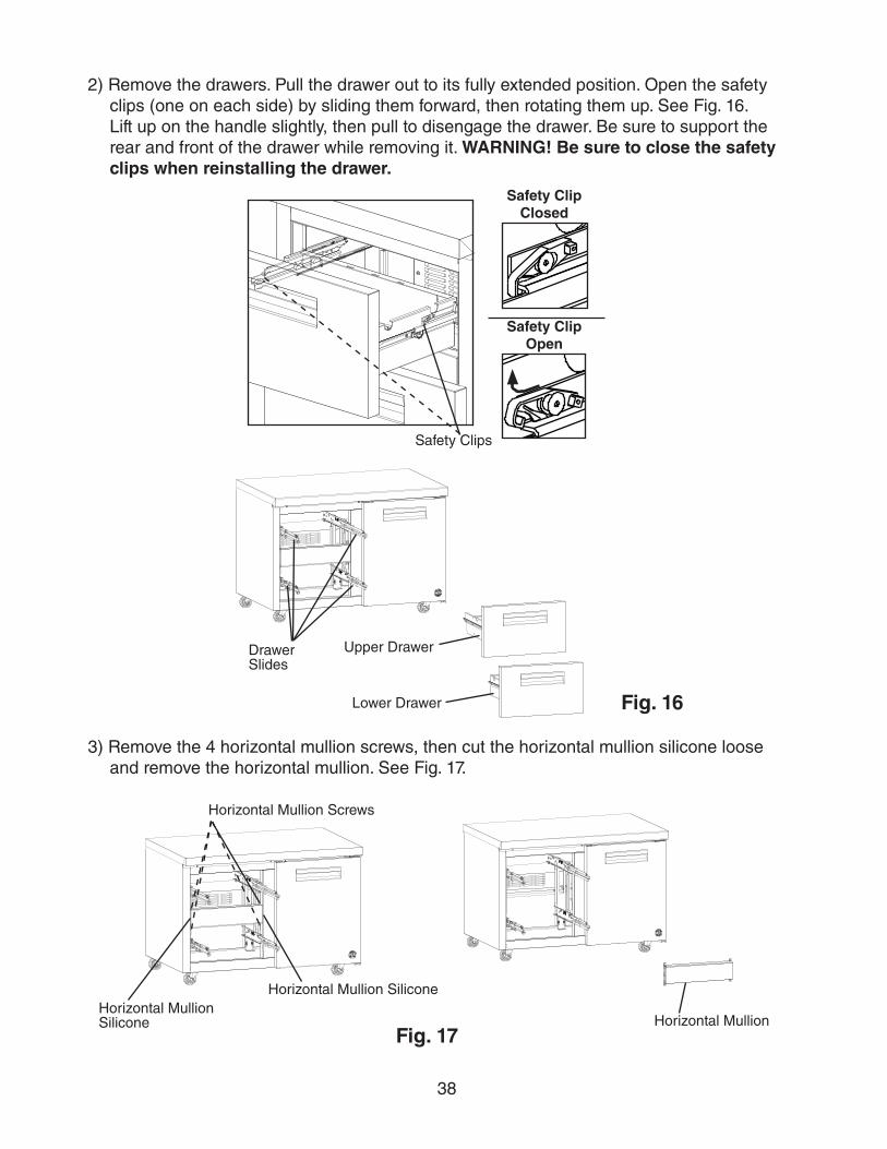
2) Remove the drawers. Pull the drawer out to its fully extended position. Open the safety clips (one on each side) by sliding them forward, then rotating them up. See Fig. 16. Lift up on the handle slightly, then pull to disengage the drawer. Be sure to support the rear and front of the drawer while removing it. WARNING! Be sure to close the safety clips when reinstalling the drawer.
3) Remove the 4 horizontal mullion screws, then cut the horizontal mullion silicone loose and remove the horizontal mullion. See Fig. 17.
Upper Drawer
Lower Drawer
Drawer Slides
Fig. 16
Safety Clips
Safety Clip Closed
Safety Clip Open
Fig. 17
Horizontal Mullion Screws
Horizontal Mullion Silicone
Horizontal Mullion Silicone
Horizontal Mullion
39
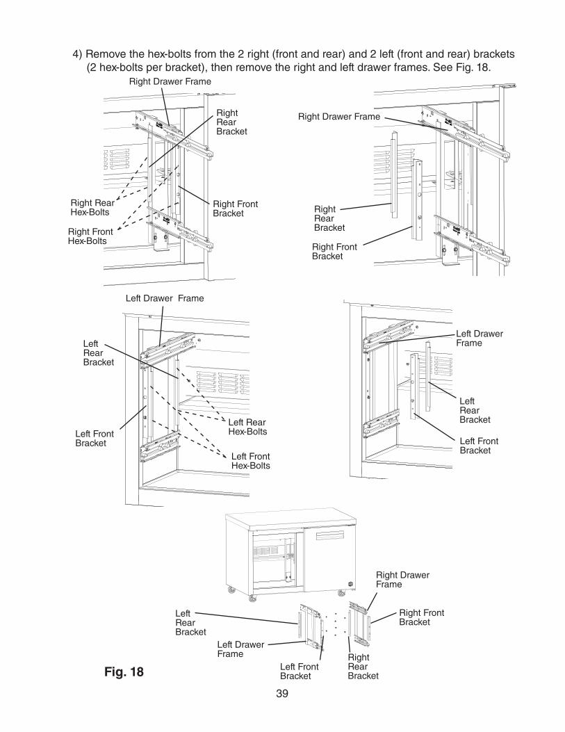
4) Remove the hex-bolts from the 2 right (front and rear) and 2 left (front and rear) brackets (2 hex-bolts per bracket), then remove the right and left drawer frames. See Fig. 18.
Fig. 18
Right Rear Hex-Bolts
Right Front Hex-Bolts
Left Drawer Frame
Right Drawer Frame
Right Drawer Frame
Left Rear Hex-Bolts
Left Front Hex-Bolts
Left Drawer Frame
Left Rear Bracket
Left Front Bracket
Right Rear Bracket
Right Front Bracket
Left Rear Bracket
Left Front Bracket
Left Rear Bracket
Left Front Bracket
Right Rear Bracket
Right Front Bracket
Left Drawer Frame
Right Rear Bracket
Right Front Bracket
Right Drawer Frame
40
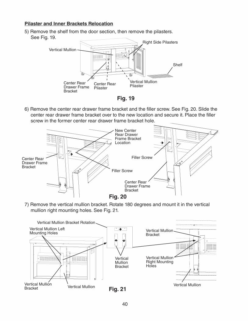
Pilaster and Inner Brackets Relocation
5) Remove the shelf from the door section, then remove the pilasters. See Fig. 19.
Shelf
Right Side Pilasters
Fig. 19
Center Rear Drawer Frame Bracket
Vertical Mullion PilasterCenter Rear
Pilaster
Vertical Mullion
6) Remove the center rear drawer frame bracket and the filler screw. See Fig. 20. Slide the center rear drawer frame bracket over to the new location and secure it. Place the filler screw in the former center rear drawer frame bracket hole.
Fig. 20
Center Rear Drawer Frame Bracket
Center Rear Drawer Frame Bracket
New Center Rear Drawer Frame Bracket Location
Filler Screw
Filler Screw
7) Remove the vertical mullion bracket. Rotate 180 degrees and mount it in the vertical mullion right mounting holes. See Fig. 21.
Fig. 21Vertical Mullion Bracket
Vertical Mullion Bracket Rotation
Vertical Mullion Vertical Mullion
Vertical Mullion Bracket
Vertical Mullion Bracket
Vertical Mullion Right Mounting Holes
Vertical Mullion Left Mounting Holes
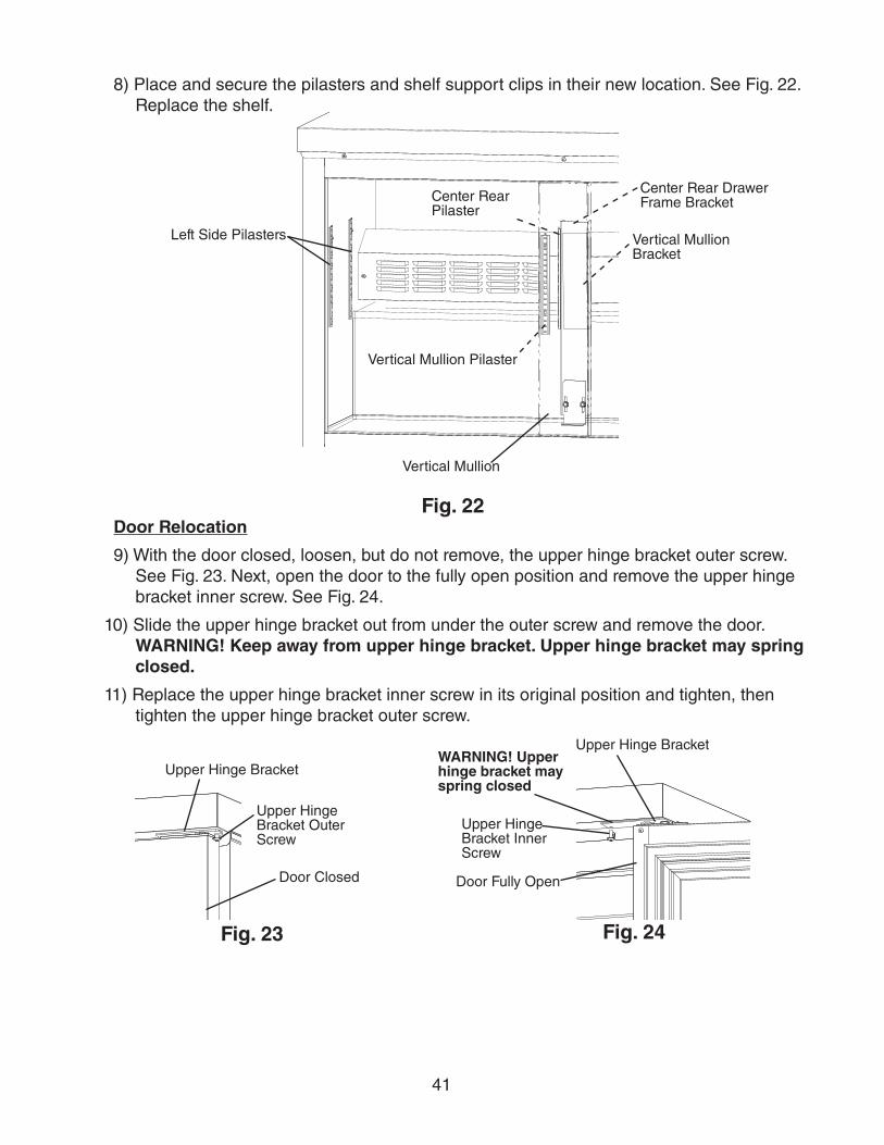
41
8) Place and secure the pilasters and shelf support clips in their new location. See Fig. 22. Replace the shelf.
Left Side Pilasters
Center Rear Pilaster
Vertical Mullion Pilaster
Center Rear Drawer Frame Bracket
Vertical Mullion
Vertical Mullion Bracket
Fig. 22Door Relocation
9) With the door closed, loosen, but do not remove, the upper hinge bracket outer screw. See Fig. 23. Next, open the door to the fully open position and remove the upper hinge bracket inner screw. See Fig. 24.
10) Slide the upper hinge bracket out from under the outer screw and remove the door. WARNING! Keep away from upper hinge bracket. Upper hinge bracket may spring closed.
11) Replace the upper hinge bracket inner screw in its original position and tighten, then tighten the upper hinge bracket outer screw.
Upper Hinge Bracket Outer Screw
Door Closed
Upper Hinge Bracket Inner Screw
Door Fully Open
WARNING! Upper hinge bracket may spring closed
Fig. 23
Upper Hinge Bracket
Upper Hinge Bracket
Fig. 24
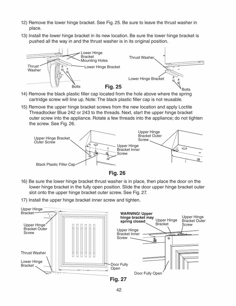
42
12) Remove the lower hinge bracket. See Fig. 25. Be sure to leave the thrust washer in place.
13) Install the lower hinge bracket in its new location. Be sure the lower hinge bracket is pushed all the way in and the thrust washer is in its original position.
Lower Hinge Bracket
Bolts
Thrust Washer
Lower Hinge Bracket
Bolts
Thrust Washer
Fig. 25
Lower Hinge Bracket Mounting Holes
14) Remove the black plastic filler cap located from the hole above where the spring cartridge screw will line up. Note: The black plastic filler cap is not reusable.
15) Remove the upper hinge bracket screws from the new location and apply Loctite Threadlocker Blue 242 or 243 to the threads. Next, start the upper hinge bracket outer screw into the appliance. Rotate a few threads into the appliance; do not tighten the screw. See Fig. 26.
Fig. 26
Upper Hinge Bracket Outer Screw
Upper Hinge Bracket Inner Screw
Black Plastic Filler Cap
Upper Hinge Bracket Outer Screw
16) Be sure the lower hinge bracket thrust washer is in place, then place the door on the lower hinge bracket in the fully open position. Slide the door upper hinge bracket outer slot onto the upper hinge bracket outer screw. See Fig. 27.
17) Install the upper hinge bracket inner screw and tighten.
Upper Hinge Bracket Inner Screw
Door Fully Open
WARNING! Upper hinge bracket may spring closed
Fig. 27
Upper Hinge Bracket Outer ScrewUpper Hinge
Bracket Outer Screw
Door Fully Open
Lower Hinge Bracket
Upper Hinge Bracket
Thrust Washer
Upper Hinge Bracket
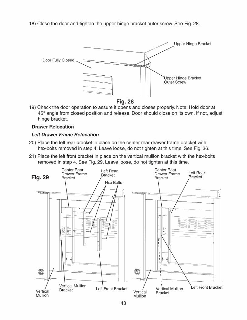
43
18) Close the door and tighten the upper hinge bracket outer screw. See Fig. 28.
Upper Hinge Bracket Outer Screw
Upper Hinge Bracket
Door Fully Closed
Fig. 2819) Check the door operation to assure it opens and closes properly. Note: Hold door at
45° angle from closed position and release. Door should close on its own. If not, adjust hinge bracket.
Drawer Relocation
Left Drawer Frame Relocation
20) Place the left rear bracket in place on the center rear drawer frame bracket with hex-bolts removed in step 4. Leave loose, do not tighten at this time. See Fig. 36.
21) Place the left front bracket in place on the vertical mullion bracket with the hex-bolts removed in step 4. See Fig. 29. Leave loose, do not tighten at this time.
Center Rear Drawer Frame BracketFig. 29
Vertical Mullion
Hex-Bolts
Left Rear Bracket
Left Front BracketVertical Mullion Bracket
Left Rear Bracket
Center Rear Drawer Frame Bracket
Left Front BracketVertical Mullion
Vertical Mullion Bracket
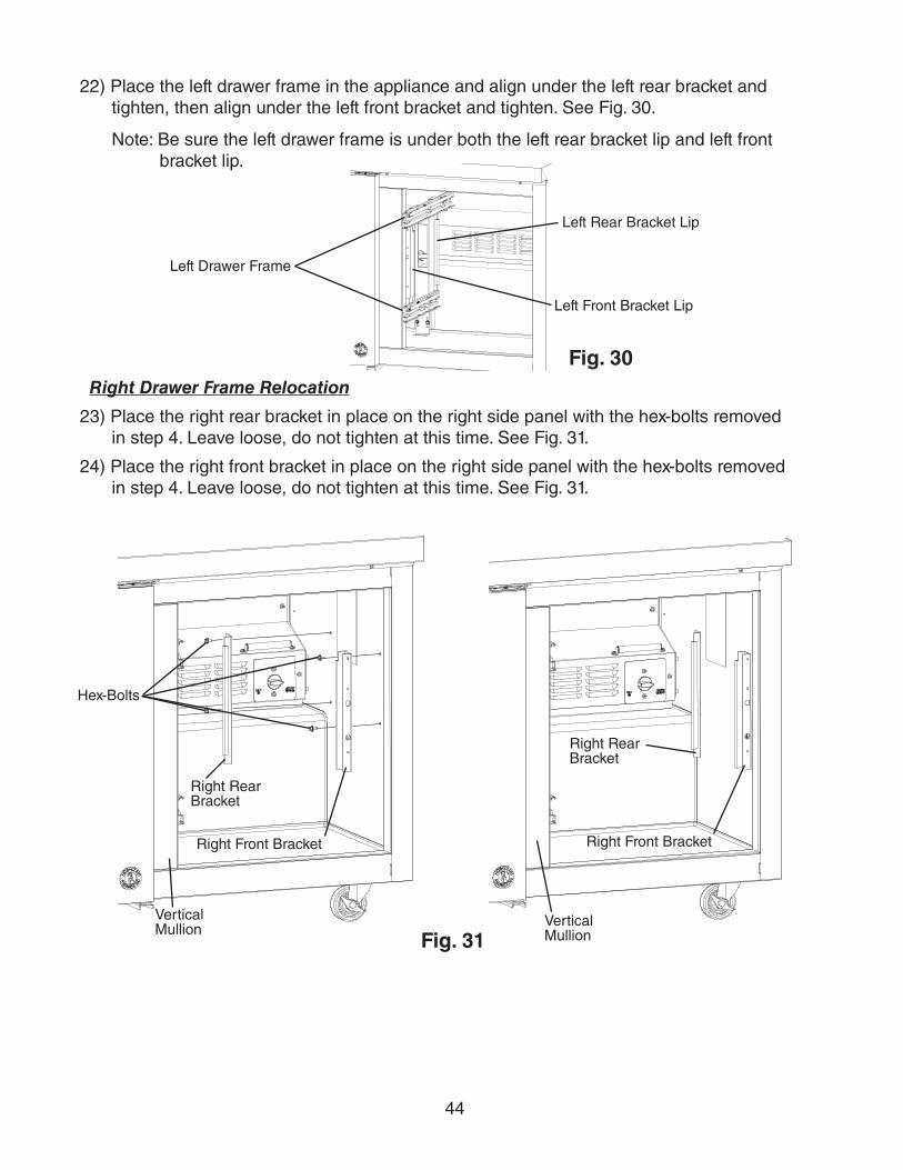
44
22) Place the left drawer frame in the appliance and align under the left rear bracket and tighten, then align under the left front bracket and tighten. See Fig. 30.
Note: Be sure the left drawer frame is under both the left rear bracket lip and left front bracket lip.
Left Drawer Frame
Fig. 30
Left Rear Bracket Lip
Left Front Bracket Lip
Right Drawer Frame Relocation
23) Place the right rear bracket in place on the right side panel with the hex-bolts removed in step 4. Leave loose, do not tighten at this time. See Fig. 31.
24) Place the right front bracket in place on the right side panel with the hex-bolts removed in step 4. Leave loose, do not tighten at this time. See Fig. 31.
Vertical Mullion
Hex-Bolts
Right Rear Bracket
Right Front Bracket
Right Rear Bracket
Right Front Bracket
Vertical Mullion Fig. 31
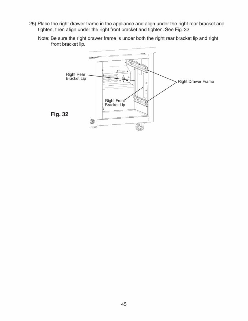
45
25) Place the right drawer frame in the appliance and align under the right rear bracket and tighten, then align under the right front bracket and tighten. See Fig. 32.
Note: Be sure the right drawer frame is under both the right rear bracket lip and right front bracket lip.
Fig. 32
Right Drawer Frame
Right Rear Bracket Lip
Right Front Bracket Lip
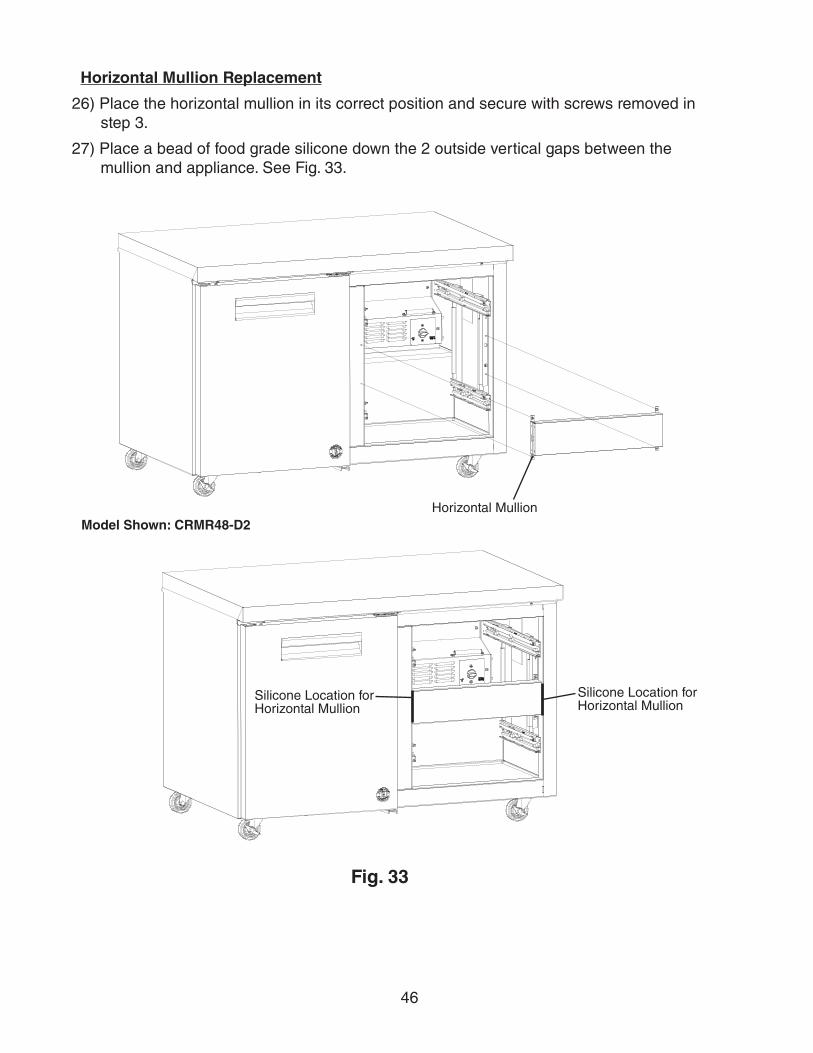
46
Horizontal Mullion Replacement
26) Place the horizontal mullion in its correct position and secure with screws removed in step 3.
27) Place a bead of food grade silicone down the 2 outside vertical gaps between the mullion and appliance. See Fig. 33.
Fig. 33
Horizontal Mullion
Silicone Location for Horizontal Mullion
Silicone Location for Horizontal Mullion
Model Shown: CRMR48-D2
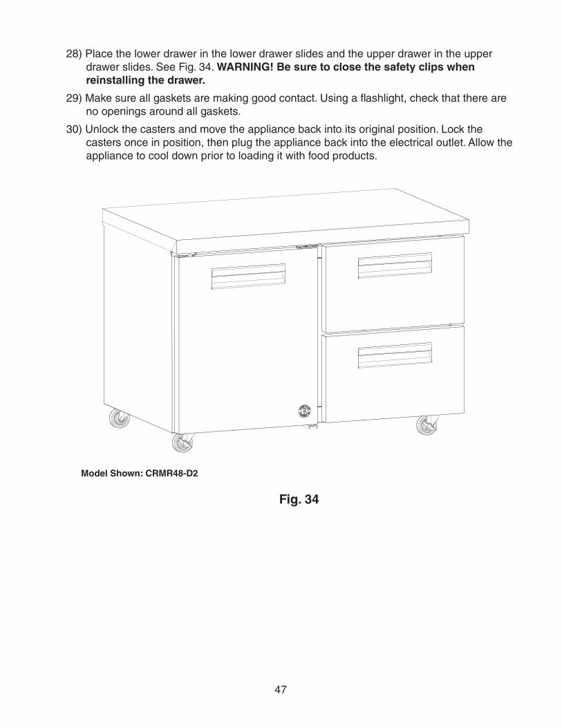
47
28) Place the lower drawer in the lower drawer slides and the upper drawer in the upper drawer slides. See Fig. 34. WARNING! Be sure to close the safety clips when reinstalling the drawer.
29) Make sure all gaskets are making good contact. Using a flashlight, check that there are no openings around all gaskets.
30) Unlock the casters and move the appliance back into its original position. Lock the casters once in position, then plug the appliance back into the electrical outlet. Allow the appliance to cool down prior to loading it with food products.
Fig. 34
Model Shown: CRMR48-D2
48
V. Preparing the Appliance for Periods of Non-UseWhen shutting down the appliance for periods of non-use, follow the instructions below.
WARNINGPrevent the doors from closing to reduce the risk of children getting trapped.
NOTICEClean the cabinet interior, door gaskets, and shelves.
1) Before shutting down the appliance, move the stored food into another refrigerator or freezer.
2) Unplug the appliance. WARNING! To reduce the risk of electric shock, do not touch the plug with damp hands.
49
VI. DisposalWhen disposing of the appliance, follow the instructions below.
WARNINGRemove the door to reduce the risk of children getting trapped. Leave the shelves in place so that children may not easily climb inside.
This appliance contains refrigerant and must be disposed of in accordance with applicable national, state, and local codes and regulations. Refrigerant must be recovered by properly certified service personnel.
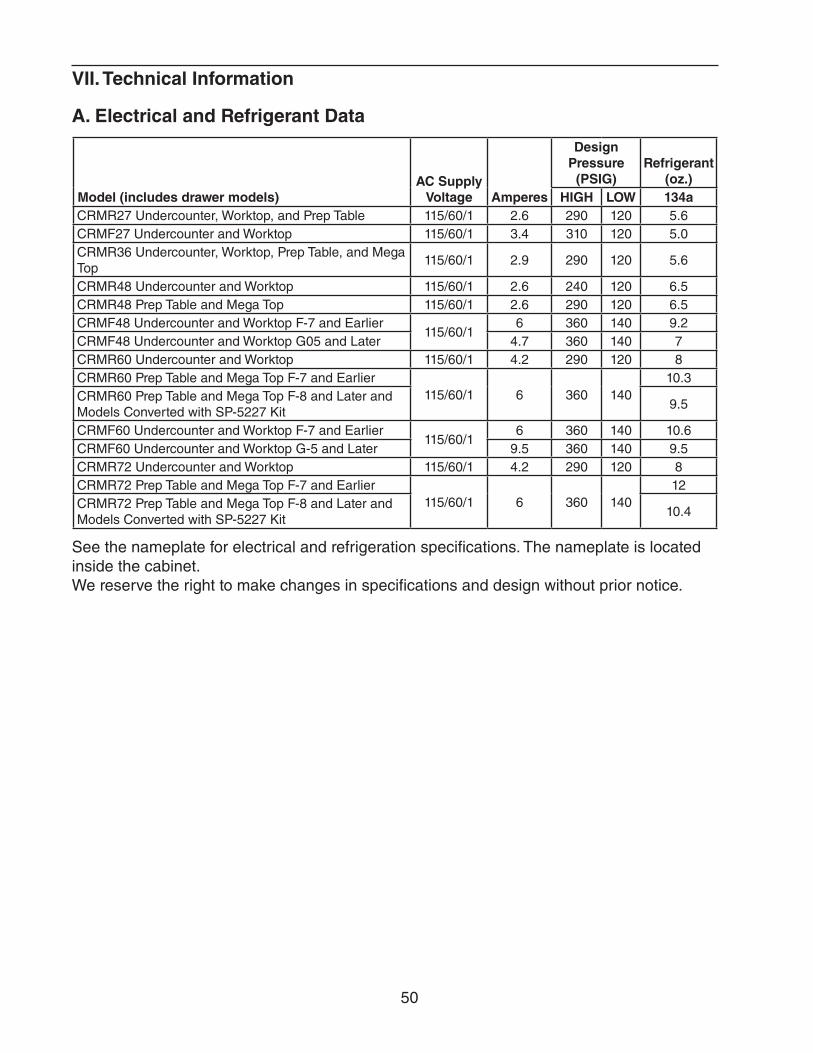
50
VII. Technical Information
A. Electrical and Refrigerant Data
Model (includes drawer models)AC Supply
Voltage Amperes
Design Pressure
(PSIG)Refrigerant
(oz.)HIGH LOW 134a
CRMR27 Undercounter, Worktop, and Prep Table 115/60/1 2.6 290 120 5.6CRMF27 Undercounter and Worktop 115/60/1 3.4 310 120 5.0CRMR36 Undercounter, Worktop, Prep Table, and Mega Top
115/60/1 2.9 290 120 5.6
CRMR48 Undercounter and Worktop 115/60/1 2.6 240 120 6.5CRMR48 Prep Table and Mega Top 115/60/1 2.6 290 120 6.5CRMF48 Undercounter and Worktop F-7 and Earlier
115/60/16 360 140 9.2
CRMF48 Undercounter and Worktop G05 and Later 4.7 360 140 7CRMR60 Undercounter and Worktop 115/60/1 4.2 290 120 8CRMR60 Prep Table and Mega Top F-7 and Earlier
115/60/1 6 360 14010.3
CRMR60 Prep Table and Mega Top F-8 and Later and Models Converted with SP-5227 Kit
9.5
CRMF60 Undercounter and Worktop F-7 and Earlier115/60/1
6 360 140 10.6CRMF60 Undercounter and Worktop G-5 and Later 9.5 360 140 9.5CRMR72 Undercounter and Worktop 115/60/1 4.2 290 120 8CRMR72 Prep Table and Mega Top F-7 and Earlier
115/60/1 6 360 14012
CRMR72 Prep Table and Mega Top F-8 and Later and Models Converted with SP-5227 Kit
10.4
See the nameplate for electrical and refrigeration specifications. The nameplate is located inside the cabinet.We reserve the right to make changes in specifications and design without prior notice.
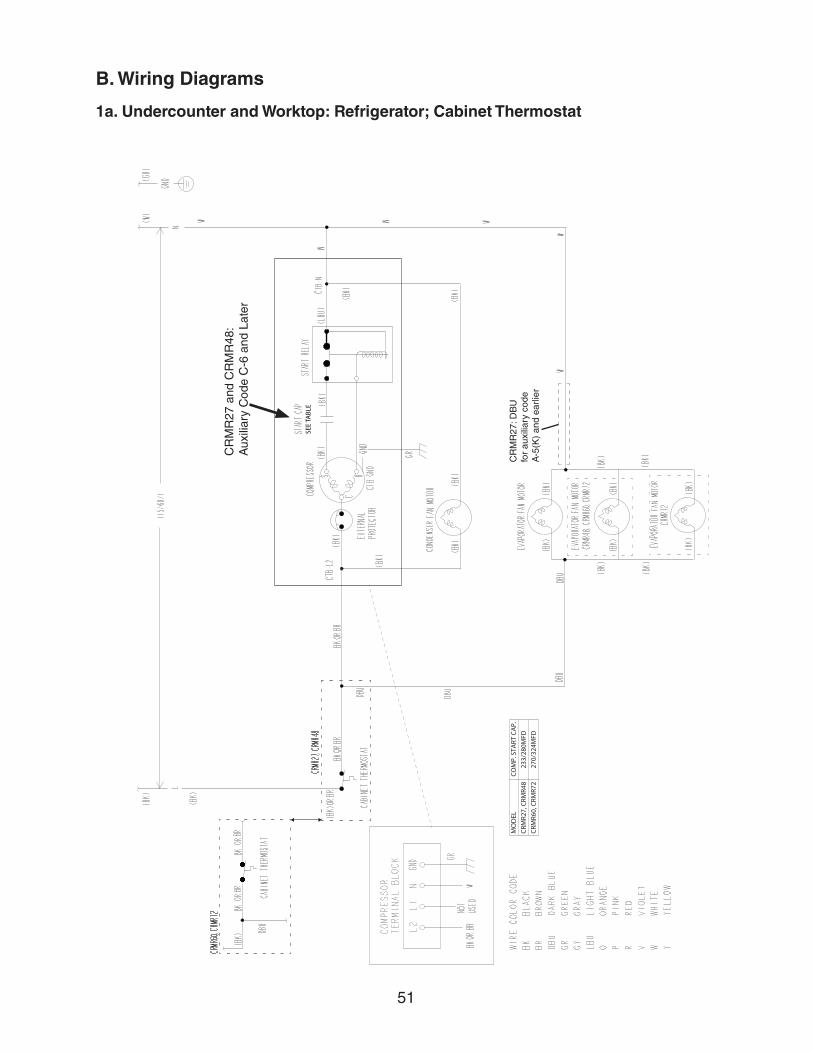
51
B. Wiring Diagrams
1a. Undercounter and Worktop: Refrigerator; Cabinet Thermostat
CR
MR
27 a
nd C
RM
R48
: A
uxili
ary
Cod
e C
-6 a
nd L
ater
CR
MR
27: D
BU
fo
r au
xilia
ry c
ode
A-5
(K)
and
earli
er
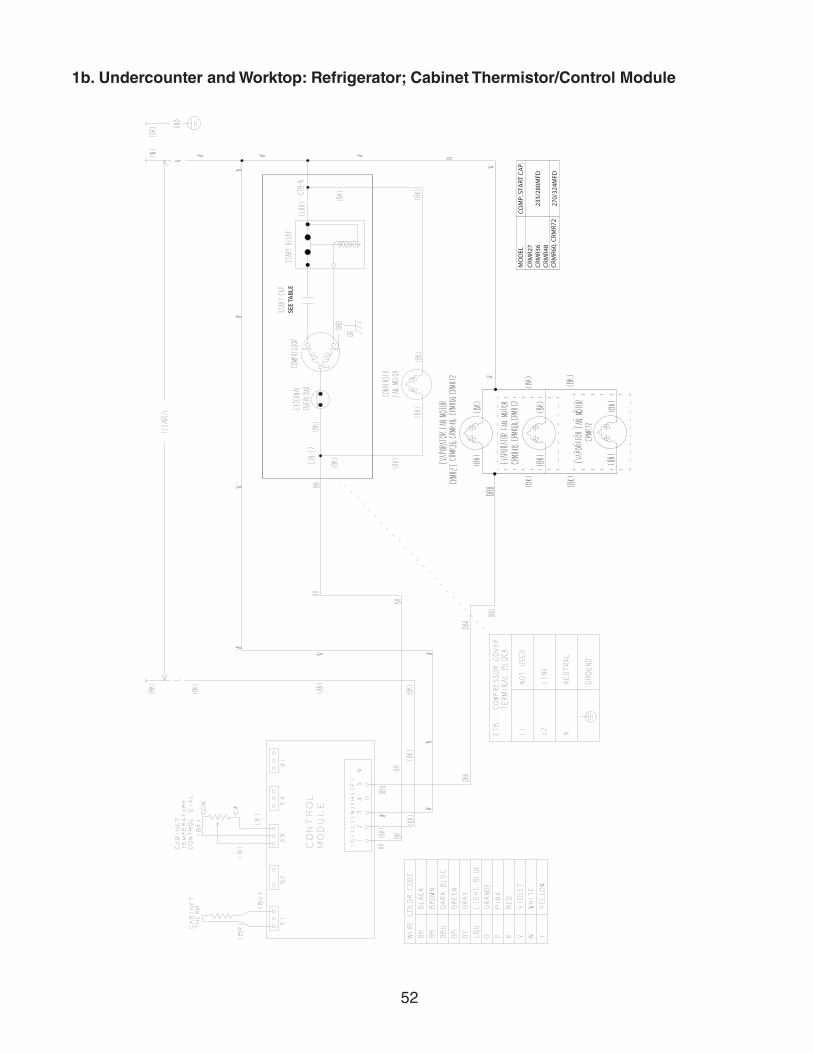
52
1b. Undercounter and Worktop: Refrigerator; Cabinet Thermistor/Control Module
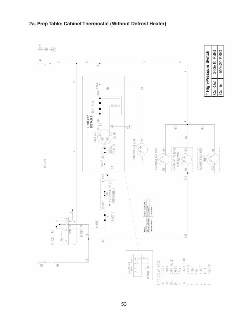
53
*
2a. Prep Table; Cabinet Thermostat (Without Defrost Heater)
* H
igh
-Pre
ssu
re S
wit
ch
Cut
-Out
300±
10 P
SIG
Cut
-In
190±
20 P
SIG
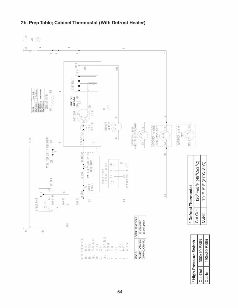
54
2b. Prep Table; Cabinet Thermostat (With Defrost Heater)
* H
igh
-Pre
ssu
re S
wit
ch
Cut
-Out
300±
10 P
SIG
Cut
-In
190±
20 P
SIG
*
* D
efro
st T
her
mo
stat
Cut
-Out
120°
F±
5°F
(49
°C±
3°C
)
Cut
-In
70°F
±5°
F (
21°C
±3°
C)
**
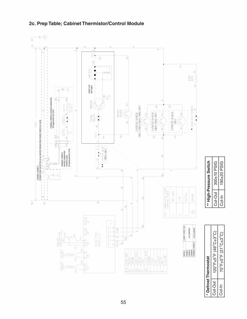
55
2c. Prep Table; Cabinet Thermistor/Control Module
* D
efro
st T
her
mo
stat
Cut
-Out
120°
F±
5°F
(49
°C±
3°C
)
Cut
-In
70°F
±5°
F (
21°C
±3°
C)
*
** H
igh
-Pre
ssu
re S
wit
ch
Cut
-Out
300±
10 P
SIG
Cut
-In
190±
20 P
SIG**
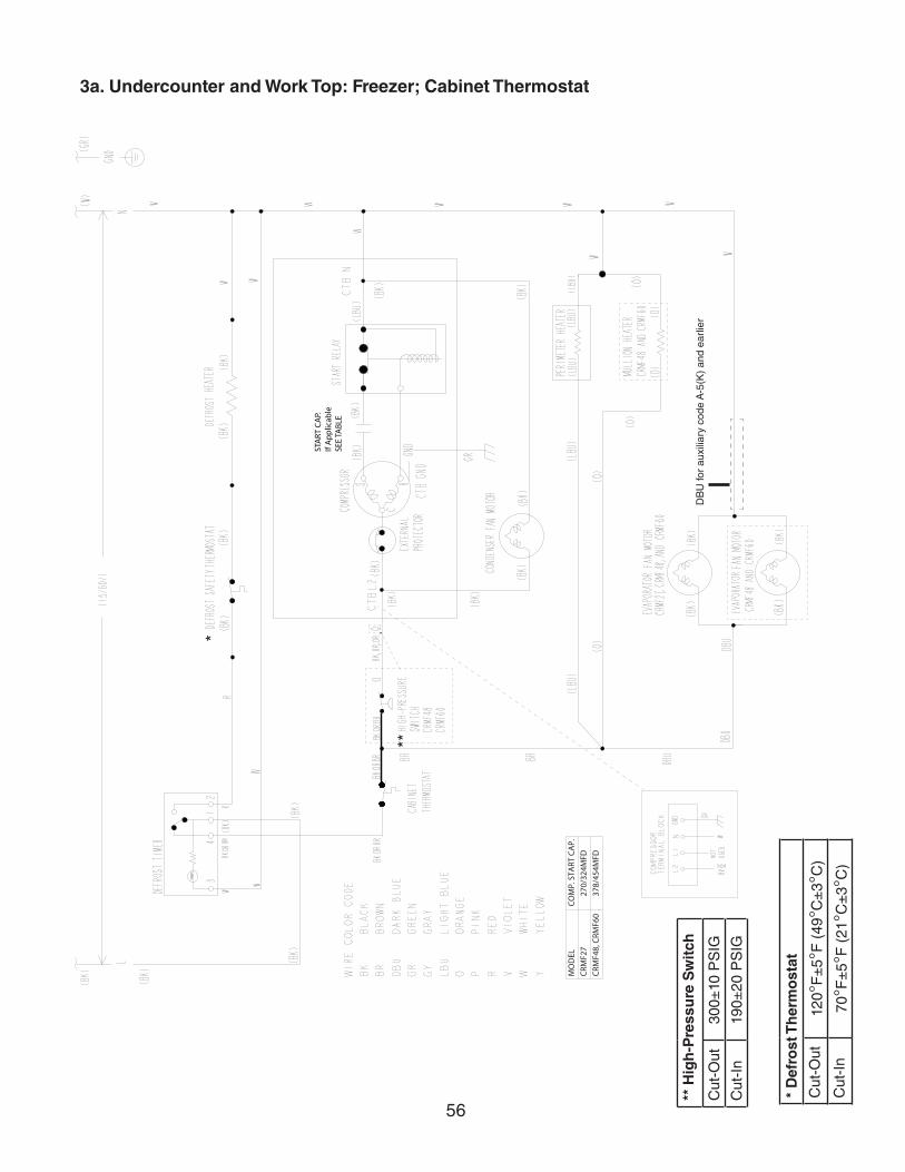
56
3a. Undercounter and Work Top: Freezer; Cabinet Thermostat
* D
efro
st T
her
mo
stat
Cut
-Out
120°
F±
5°F
(49
°C±
3°C
)
Cut
-In
70°F
±5°
F (
21°C
±3°
C)
*
DB
U fo
r au
xilia
ry c
ode
A-5
(K)
and
earli
er
**
** H
igh
-Pre
ssu
re S
wit
ch
Cut
-Out
300±
10 P
SIG
Cut
-In
190±
20 P
SIG
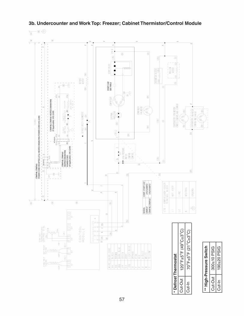
57
3b. Undercounter and Work Top: Freezer; Cabinet Thermistor/Control Module
** H
igh
-Pre
ssu
re S
wit
ch
Cut
-Out
300±
10 P
SIG
Cut
-In
190±
20 P
SIG
* D
efro
st T
her
mo
stat
Cut
-Out
120°
F±
5°F
(49
°C±
3°C
)
Cut
-In
70°F
±5°
F (
21°C
±3°
C)
**
*