service manual - fuller transmission, spicer, rockwell ... manual fuller mid-range transmissions ......
TRANSCRIPT

Fuller® Mid-Range Transmissions
Service ManualFuller Mid-Range Transmissions
TRSM0180
October 2007
FS-7206A
More time on the road ®

For parts or service call us Pro Gear & Transmission, Inc.
1 (877) 776-4600
(407) 872-1901
906 W. Gore St.
Orlando, FL 32805

WARNINGBefore starting a vehicle always beseated in the drivers seat, place thetransmission in neutral, set the park-ing brakes and disengage the clutch.
Before working on a vehicle place thetransmission in neutral, set the park-ing brakes and block the wheels.
Before towing the vehicle place thetransmission in neutral, and lift therear wheels off the ground or discon-nect the driveline to avoid damage tothe transmission during towing.

TABLE OF CONTENTS
FOREWORD
MODEL DESIGNATIONS AND SPECIFICATIONS
LUBRICATION.
OPERATION
POWER FLOW
TORQUE RECOMMENDATIONS
PREVENTIVE MAINTENANCE
P R E C A U T I O N S
DISASSEMBLY
INSPECTION
REASSEMBLY
DISASSEMBLY AND REASSEMBLY–SHIFTING CONTROLS
GEARSHIFT LEVER HOUSING ASSEMBLY
SHIFT BAR HOUSING ASSEMBLY
REMOVAL – OUTPUT YOKE AND CLUTCH HOUSING
DISASSEMBLY – TRANSMISSION
REASSEMBLY – TRANSMISSION
INSTALLATION–CLUTCH HOUSING AND OUTPUT YOKE
INSTALLATION–SHIFTING CONTROLS
SHIFT BAR HOUSING ASSEMBLY
GEARSHIFT LEVER HOUSING ASSEMBLY

FOREWORDThis manual is designed to provide detailed informa-tion necessary to service and repair the Eaton®
Fuller® Transmission listed on the cover.As outlined in the Table of Contents, the manual is
divided into 3 main sections:a. Technical information and referenceb. Removal, disassembly, reassembly and
installationc. Options
The format of the manual is designed to befollowed in its entirety if complete disassembly andreassembly of the transmission is necessary. But ifonly one component of the transmission needs to berepaired, refer to the Table of Contents for the pagenumbers showing that component. For example, ifyou need to work on the Shift Bar Housing, you willfind instructions for removal, disassembly and reas-sembly on page 18. Instructions for installation are onpage 62. Service Manuals, Illustrated Parts Lists,Drivers Instructions, and other forms of product
*Note to Canadian Residents:Please do not use the order form in the back of thismanual. A special Canadian Product Literature OrderForm may be obtained by contacting the following:
service information for these and other Fuller Trans-missions are available upon request. A TechnicalLiterature Order Form may be found in the back of thismanual*. You may also obtain Service Bulletins,detailing information on product improvements, repairprocedures and other service-related subjects bywriting to the following address:
EATON CORPORATIONTRANSMISSION DIVISIONTechnical Service DepartmentP.O. Box 4013Kalamazoo, Michigan 49003(61 6) 342-3344
EATON CORPORATIONTRANSMISSION DIVISIONP.O. Box 1368Benton Harbor, Ml 49022(61 6) 342-3344

MODEL DESIGNATIONSAND SPECIFICATIONS
Specifications:
IMPORTANT: All Eaton Fuller Transmissions areidentified by model and serial number. This infor-mation is stamped on the transmission identifica-tion tag and affixed to the case.DO NOT REMOVE OR DESTROY THE TRANS-MISSION IDENTIFICATION TAG.
Relative Speed Note 2 Note 3Gear Ratios PTO Gear to Weight Oil Capacity
No. Input R PM Lbs PintsModel Speeds 1 St 2nd 3rd 4th 5th 6th Reverse Left Right (Kg.) (Liters)
28.47 392 21FS-7206 6 9.00 4.98 2.98 1.89 1.32 1. 00 800 455 455
(723.1) (177.8) (10.0)
Note 1Length
I n .( m m )
See Chart Notes.
CHART NOTES:1. Lengths measured from face of clutch housing to rear of speedo gear.2. Weights include shift bar housing and end yoke, clutch housing, less tower assembly and clutch release
parts. For more information on available clutch housings, refer to the transmission’s Illustrated Parts List orthe Super Parts Book. All weights are approximate.
3. Oil capacities are approximate, depending on inclination of engine and transmission. Always fill transmis-sion with proper grade and type of lubricant to level of filler opening. See LUBRICATION.
LUBRICATION
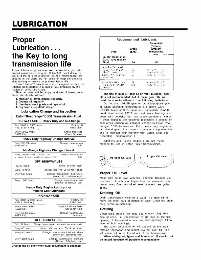
I Recommended LubricantsProperLubrication . . .the Key to longtransmission lifeProper lubrication procedures are the key to a good all-around maintenance program, If the 011 IS not doing itsjob, or if the oil level IS ignored, all the maintenance pro-cedures in the world are not going to keep the transmis-sion running or assure long transmission Iife.
Eaton® Fuller® Transmlsslons are designed so that theInternal parts operate in a bath of 011 circulated by themotion of gears and shafts.
Thus, all parts wIII be amply lubricated if these proce-dures are closely followed:
1. Maintain oil level. Inspect regularly.2. Change oil regularly.3. Use the correct grade and type of oil.4. Buy from a reputable dealer.
Lubrication Change and Inspection—Eaton® Roadranger® CD50 Transmission FluidHIGHWAY USE — Heavy Duty and Mid-Range
First 3,000 to 5000 miles Factory fill(4827 to 8045 Km) Initial drain
—-Every 10,000 rniles Check fluid-level(16090 Km) Check for leaks
Heavy Duty Highway Change IntervalEvery 250,000 miles Change transmission(402336 Km) fluid
Mid-Range Highway Change IntervalEvery 100,000 miles (160,000 Km) Change transmissionor every 3 years whichever occurs first f lu id
OFF. HIGHWAY USEFirst 30 hours Factory fill initial drain
Every 40 hours Inspect f luid-level Check for leaks
Every 500 hours Change transmission fluid wheresevere dirt conditions exist
Every 1,000 hours Change transmission fluid(Normal off-highway use)
Heavy Duty Engine Lubricant orMineral Gear Lubricant
HIGHWAY USEFirst 3000 to 5000 miles Factory fill(4827 to 8045 Km) Initlal drain
Every 10000 miles Inspect Iubricant level(16090 Km) Check for leaks
Every 50,000 miles Change transmission(80450 Km) lubricant
OFF-HIGHWAY USEFirst 30 hours Change transmission Iubricant on new units
Every 40 hours Inspect lubricant level Check for leaks
Every 500 hours Change transmisslon Iubricant wheresevere dirt conditions exist
Every 1000 hours Change transmission Iubricant(Normal off-highway use)
Fahrenheit(Celsius)
Grade AmbientType (SAE) Temperature
The use of mild EP gear oil or multi-purpose gearoil is not recommended, but if these gear oils areused, be sure to adhere to the following limitations:
Do not use mild EP gear oil or multi-purpose gearoil when operating temperatures are above 230°F(110°C). Many of these gear oils, particularly 85W140,break down above 230°F and coat seals, bearings andgears with deposits that may cause premature failures.If these deposits are observed (especially a coating onseal areas causing oil leakage), change to Eaton Roa-dranger CD50 transmission fluid, heavy duty engine oilor mineral gear oil to assure maximum component lifeand to maintain your warranty with Eaton. (Also see“Operating Temperatures”. )
Additives and friction modifiers are not recom-mended for use in Eaton Fuller transmissions.
Proper Oil LevelMake sure oil is level with filler opening. Because youcan reach oil with your finger does not mean oil is atproper level, One inch of oil level is about one gallonof oil.
Draining OilDrain transmission while oil is warm. To drain oil re-move the drain plug at bottom ofplug before re-installing.
RefillingClean case around filler plug andside of case, Fill transmission toopening. If transmission has twolevel of both openings.
case. Clean the drain
remove plug fromthe level of the fillerfiller openings, fill to
The exact amount of oil will depend on the trans-mission inclination and model. Do not over fill—thiswill cause oil to be forced out of the transmission.
When adding oil, types and brands of oil should notbe mixed because of possible incompatibility.
Change the oil filter when fluid or lubricant is changed.

LUBRICATION
Operating Temperatures—With Eaton® Roadranger®
CD50 Transmission FluidHeavy Duty Engine Oiland Mineral Oil
The transmission should not be operated con-sistently at temperatures above 250°F (120°C).However, intermittent operating temperaturesto 300°F (149°C) will not harm the transmis-sion. Operating temperatures above 250°Fincrease the lubricant’s rate of oxidation andshorten its effective life. When the averageoperating temperature is above 250°F, thetransmission may require more frequent oilchanges or external cooling.
The following conditions in any combina-tion can cause operating temperatures of over250°F: (1) operating consistently at slowspeeds, (2) high ambient temperatures, (3) re-stricted air flow around transmission, (4) ex-haust system too close to transmission, (5)high horsepower, overdrive operation.
External oil coolers are available to reduceoperating temperatures when the above condi-tions are encountered.
Transmission Oil Coolers are:
Recommended
— With engines of 350 H.P. and abovewith overdrive transmissions
Required— With engines 399 H.P. and above with
overdrive transmissions and GCW’Sover 90,000 lbs.
— With engines 399 H.P. and above and1400 Lbs.-Ft. or greater torque
— With engines 450 H.P. and above
— With EP or Multipurpose Gear OilMild EP gear oil and multipurpose gear oil arenot recommended when lubricant operatingtemperatures are above 230°F (110°C). In addi-tion, transmission oil coolers are not recom-mended with these gear oils since the oilcooler materials may be attacked by thesegear oils. The lower temperature limit and oilcooler restriction with these gear oils gener-ally limit their success to milder applications.
Proper Lubrication Levelsas Related to TransmissionInstallation AnglesIf the transmission operating angle is morethan 12 degrees, improper lubrication can oc-cur. The operating angle is the transmissionmounting angle in the chassis plus the per-cent of upgrade (expressed in degrees).
The chart below illustrates the safe percentof upgrade on which the transmission can beused with various chassis mounting angles.For example: if you have a 4 degree transmis-sion mounting angle, then 8 degrees (or 14percent of grade) is equal to the limit of 12degrees. If you have a 0 degree mountingangle, the transmission can be operated on a12 degree (21 percent) grade.
Anytime the transmission operating angle of12 degrees is exceeded for an extendedperiod of time the transmission should beequipped with an oil pump or cooler kit toinsure proper lubrication.
Note on the chart the effect low oil levelscan have on safe operating angles. Allowingthe oil level to fall 1/2” below the filler plughole reduces the degree of grade by approxi-mately 3 degrees (5.5 percent).
Proper Lubrication Levels are Essential!
Transmission Mounting AngleDotted line showing “2 Quarts Low” is forreference only. Not recommended.

OPERATIONGear Shift Lever Pattern and Shifting Instructions
Follow the simple 6-speed shift pattern . . .
I Cut 8003 T-11/88
General InformationFS-7206A transmissions have six forward speeds and one reverse, and are shifted as you would shift any syn-chronized manual transmission, following the simple 6-speed shift pattern.
Driving Tips
●
●
●
●
●
●
●
Always use the clutch when making upshifts or downshifts. Premature synchronizer failure can resultfrom not using the clutch.
Always select a starting gear that will provide sufficient reduction for the load and terrain.
Do not double clutch upshifts or downshifts.
Never downshift at too high of a road speed.
Never slam or jerk the shift lever to complete gear engagement.
Never coast with the transmission in neutral and the clutch dis-engaged.
Although the FS-7206 transmission’s first gear is synchronized, it is advised that a downshift into firstgear be completed at very slow vehicle speed to prevent engine over speed.
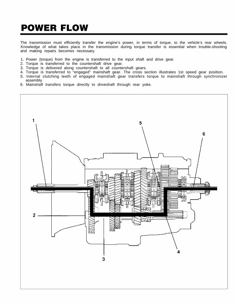
POWER FLOWThe transmission must efficiently transfer the engine’s power, in terms of torque, to the vehicle’s rear wheels.Knowledge of what takes place in the transmission during torque transfer is essential when trouble-shootingand making repairs becomes necessary.
1. Power (torque) from the engine is transferred to the input shaft and drive gear.2. Torque is transferred to the countershaft drive gear.3. Torque is delivered along countershaft to all countershaft gears.4. Torque is transferred to “engaged” mainshaft gear. The cross section illustrates 1st speed gear position.5. Internal clutching teeth of engaged mainshaft gear transfers torque to mainshaft through synchronizer
assembly.6. Mainshaft transfers torque directly to driveshaft through rear yoke.

TORQUE RECOMMENDATIONSCorrect torque application is extremely important to assure long transmission life. Over-tightening or under-tightening of fasteners can result in a loose installation and, in many instances, eventually cause damage to thetransmission. Use a torque wrench to attain recommended torque ratings. Do not torque capscrews dry.

TORQUE RECOMMENDATIONS

PREVENTIVE MAINTENANCE
PREVENTIVE MAINTENANCE
PREVENTIVE MAINTENANCE CHECK CHARTCHECKS WITHOUT PARTIALDISASSEMBLY OF CHASSIS OR CAB
1.
2.
3.
4.
5.
6.
7.
Clutch Housing Mountinga. Check all capscrews of clutch housing
flange for looseness.
Clutch Release Bearing (Not Shown)a. Remove hand hole cover and check radial
and axial clearance in release bearing.b. Check relative position of thrust surface of
release bearing with thrust sleeve on push-type clutches.
Clutch Pedal Shaft and Boresa. Pry upward on shafts to check wear.
b. If excessive movement is found, removeclutch release mechanism and check bush-ings in bores and wear on shafts.
Lubricanta. Change at specified service intervals.b. Use only the types and grades as recom-
mended. See LUBRICATION.
Filler and Drain Plugsa. Remove filler plug and check level of lubri-
cant at specified intervals. Tighten filler anddrain plugs securely.
Capscrews, Retaining Nutsand Gasketsa. Check all capscrews, especially those on
PTO covers, front and rear bearing covers forlooseness which would cause oil leakage.See TORQUE RECOMMENDATIONS.
b. Check PTO opening and rear bearing coversfor oil leakage.
c. Check the mainshaft rear bearing cover andcountershaft rear bearing cover shims mak-ing sure a light coat of Loctite 510 was usedon both sides of shims.
Gear Shift Levera. Check for looseness and free play in hous-
ing. If lever is loose in housing, proceed withCheck No. 8.
8. Gear Shift Lever Housing Assemblya. Remove the gear shift lever housing as-
sembly from transmission.
b. Check tension spring and washer for set andwear.
c. Check bottom end of gear shift lever forwear of slots. Also check for wear of shiftfinger assembly and shift blocks.
CHECKS WITH DRIVE LINE DROPPED
9.
10.
Universal Joint Companion Flangeor Yoke Nuta. Check for tightness. Tighten to recommend-
ed torque.
Output Shaft (Not Shown)NOTE: Pry upward against output shaft to check ra-
dial clearance in mainshaft rear bearing.
CHECKS WITH UNIVERSAL JOINTCOMPANION FLANGE OR YOKEREMOVED
NOTE: If necessary, use a clean shop rag to cleansealing surface of companion flange or yoke.DO NOT USE CROCUS CLOTH, EMERY PA-PER OR OTHER ABRASIVE MATERIALS THATWILL MAR THE REAR SEAL SEALING SUR-FACE FINISH.
11.
12.
Splines on Output Shaft(Not Shown)a. Check for wear from movement and chuck-
ing action of the universal joint companionflange or yoke.
Mainshaft Rear Bearing Covera. Check oil seal for wear.

PRECAUTIONSDisassemblyIt is assumed in the detailed assembly instructions that the lubricant has been drained from transmission, thenecessary linkage disconnected and the transmission has been removed from vehicle chassis. Removal of thegear shift lever housing assembly is included in the detailed instructions (Disassembly and Reassembly-Shift-ing Controls); however, this assembly must be detached from shift bar housing before transmission can be re-moved.
FOLLOW CLOSELY EACH PROCEDURE IN THE DETAILED INSTRUCTIONS, MAKING USE OF THE TEXT,ILLUSTRATIONS AND PHOTOGRAPHS PROVIDED.
1. BEARINGS - Carefully wash and relubricate all 4. CLEANLINESS - Provide a clean place to work. Itreusable bearings as removed and protectivelywrap until ready for use. Remove bearings plannedto be reused with pullers designed for this pur-pose.
2. ASSEMBLIES - When disassembling the variousassemblies, such as the mainshaft, countershaft, 5and shift bar housing, lay all parts on a cleanbench in the same sequence as removed. This pro-cedure will simplify reassembly and reduce thepossibility of losing parts.
3. SNAP RINGS - Remove snap rings with pliers de-signed for this purpose. Snap rings removed in thismanner can be reused, if they are not sprung orloose.
Inspection
is important that no dirt or foreign material entersthe unit during repairs. Dirt is an abrasive and candamage bearings. It is always good practice toclean the outside of the unit before starting theplanned disassembly.
WHEN USING TOOLS TO MOVE PARTS - Alwaysapply force to shafts, housings, etc, with restraint.Movement of some parts is restricted. Never applyforce to the part being driven after itThe use of soft hammers, bars anddisassembly work is recommended.
stops solidly.mauls for all
Before reassembling the transmission, check each part carefully for abnormalto determine reuse or replacement. When replacement is necessary, use onlysion parts to assure continued performance and extended life from your unit.
or excessive wear and damagegenuine Eaton Fuller Transm[s-
Sirice the cost of a new part is generally a small fraction of the total cost of downtime and labor, avoid reus-ing a questionable part which could lead to additional repairs and expense soon after initial reassembly. To aidin determining the reuse or replacement of any transmission part, consideration should also be given to theunit's history, mileage, application, etc.
Recommended inspection procedures are provided in the following checklist.
A. BEARINGS1.
2.
3.
Wash all bearings in clean solvent. Checkballs, rollers and raceways for pitting, discol-oration, and spalled areas. Replace bearingsthat are pitted, discolored, spalled, or dam-aged during disassembly.
Lubricate bearings that are not pitted, discol-ored, or spalled and check for axial and radialclearances.
Replace bearings with excessive clearances.
Check bearing f i ts. Bearing inner racesshould be tight to shaft; outer races slightlytight to slightly loose in case bore. If bearingspins freely in bore, however, case should bereplaced.
B. GEARS1. Check gear teeth for frosting and pitting.
Frosting of gear tooth faces present nothreat of transmission failure. Often in con-tinued operation of the unit, frosted gearswill "heal" and not progress to the pittingstage. In most cases, gears with light to mod-erate pitted teeth have considerable gear liferemaining and can be reused, but gears withadvanced stage pitting should be replaced.
2. Check for gears with clutching teeth abnor-mally worn, tapered, or reduced in lengthfrom clashing in shifting. Replace gearsfound in any of these conditions.

PRECAUTIONSInspection (cont'd.)
3. Check axial clearance of gears. Where exces-sive clearance is found, check gear snapring, split washer, clutch hub, and gear hubfor excessive wear.
C. SPLINES1. Check splines on all shafts for abnormal
wear. If sliding clutch gears, companionflange, or clutch hub have worn into thesides of the splines, replace the specificparts affected.
D. SPLIT WASHERS1. Check surfaces of all washers. Washers
scored or reduced in thickness should bereplaced.
E. REVERSE IDLER GEAR ASSEMBLIES1. Check for excessive wear from action of
roller bearings.
F. G RAY IRON PARTS1. Check all gray iron parts for cracks and breaks.
Replace or repair parts found to be damaged.Heavy castings may be welded or brazed pro-vided the cracks do not extend into bearingbores or bolting surfaces. When welding, how-ever, never place the ground so as to allow cur-rent to pass through the transmission.
G. CLUTCH RELEASE PARTS1. Check clutch release parts. Replace yokes
worn at cam surfaces and bearing carrierworn at contact pads.
2. Check pedal shafts. Replace those worn atbushing surfaces.
H. SHIFT BAR HOUSING ASSEMBLY1. Check for wear on shift yokes, shift blocks
and finger assembly at pads and lever slot.Replace excessively worn parts.
2. Check yokes for correct alignment. Replacesprung yokes.
3. Check Iockscrews in yoke assembly retainerplates. Tighten those found loose.
4. Check roll pins retaining shift yokes and shiftblocks for tightness. Replace broken, looseor worn roll pins.
1. GEAR SHIFT LEVER HOUSINGASSEMBLY1.
2.
Check spring tension on shift lever. Replacetension spring if lever moves too freely.
If housing is disassembled, check bottomend of gear shift lever and shift finger as-sembly for wear. Replace both parts if exces-sively worn.
J. BEARING COVERS1. Check covers for wear from thrust of adja-
cent bearing. Replace covers damaged fromthrust of bearing outer race.
2. Check bores of covers for wear. Replacethose worn oversize.
K. OIL SEALS1. Check oil seal in input shaft and rear bearing
cover. If sealing action of lip has been de-stroyed, replace seal.
L. CLUTCHING TEETH1. Check all shift yokes and shift hub of sliding
clutches for extreme wear or discolorationfrom heat.
2. Check engaging teeth of mainshaft gears forpartial engagement pattern or excessivewear.
M. SYNCHRONIZER ASSEMBLY1.
2.
3.
Check synchronizer for burrs, uneven and ex-cessive wear at contact surface, and metalparticles.
Check blocker pins for excessive wear orlooseness.
Check synchronizer contact surfaces on thesynchronizer cups for wear.
N. COUNTERSHAFT FRONT BORE PLUG1. Check for damage or misalignment during in-
stallation.
2. The bore plug's outer diameter must becoated with Loctite gasket sealant 71217.
0. O-RINGS1. Inspect the countershaft rear bearing hous-
ing for damaged O-rings.
2. Inspect the reverse idler shaft O-ring for wearor damage.

PRECAUTIONSReassemblyMake sure that interiors of case and housings are clean. It is important that dirt and other foreign materials bekept out of the transmission during reassembly. Dirt is an abrasive and can damage polished surfaces ofbearings and washers. Use certain precautions, as listed below, during reassembly.
1.
2.
3.
4.
5.
6.
GASKETS - Use new gaskets throughout thetransmission as it is being rebuilt. Make sure allgaskets are installed. An omission of any gasketcan result in oil leakage or misalignment ofbearing covers. Install PTO and shift bar housinggaskets dry.
CAPSCREWS - TO prevent oil leakage and loosen-ing, use Loctite 262, Fuller part number 71225,thread sealant on all capscrews. For torque rat-ings, see TORQUE RECOMMENDATIONS.
SHIMS - Apply a light coat of Loctite 510, Fullerpart number 71217, to both sides of shims beforefinal installation to prevent leakage.
ASSEMBLY - Refer to the illustrations provided inthe detailed disassembly instructions as a guideto reassembly.
INITIAL LUBRICATION - Coat all split washers,thrust washers, synchronizers, bearing surfaceson gears, bushings, gear working surfaces, shiftfork pads, and bearings with transmission lubri-cant during reassembly to prevent damage duringinitial start up.
END PLAY - Maintain .006 -.010 end play on coun-tershaft and mainshaft assemblies.
7.
8.
9.
10.
11.
BEARINGS - Use of a sleeve type driver thatcontacts the inner race of the bearing is recom-mended to prevent damage to the rollers andcage.
UNIVERSAL JOINT COMPANION FLANGE ORYOKE - Pull the companion flange or yoke intoplace with the output shaft nut, using 300-350foot-pounds (407-475 Nm) of torque. Make surethe speedometer drive gear or a replacementspacer has been installed. Failure to properlytorque the nut can result in damage to the main-shaft rear bearing.
OIL SEALS - Outer diameters of steel oil sealsmust have gasket sealant 71217 applied beforeinstallation. Oil seals must have grease 71215applied to the sealing surface before installation.
COUNTERSHAFT FRONT BORE PLUG - Theouter diameter of the bore plug must be coatedwith gasket sealant 71217 before installation.
CAPSCREWS, FASTENERS AND NUTS - Reusedcapscrews, fasteners and nuts must have threadsealant adhesive 71225 applied to threads beforeinstallation.
IMPORTANT: REFER TO THE APPROPRIATE ILLUSTRATED PARTS LIST(SPECIFIED BY MODEL SERIES) TO ENSURE THAT PROPER PARTSARE USED DURING REASSEMBLY OF THE TRANSMISSION.

DISASSEMBLY AND REASSEMBLYSHIFTING CONTROLS
GEARSHIFT LEVER HOUSING ASSEMBLY
A. Removal and Disassembly
1. Turn out four capscrews and remove tower assem-bly and gasket from shift bar housing.
2. Remove shift lever grip and boot from shift lever,secure assembly in vise with bottom of housingup. Use a large screwdriver to twist betweenspring and housing, forcing spring from under
15 Iugs in housing. Do one coil at a time.

DISASSEMBLY AND REASSEMBLYSHIFTING CONTROLS
GEARSHIFT LEVER HOUSING ASSEMBLY (con't.)
3. Remove tension spring, washer and gearshift lever 4. Remove spade pins from bore in housing.from housing.
B. Reassembly of Gearshift Lever Housing Assembly
1. With gearshift lever housing secured in vise as 2. Position gearshift lever in housing with spade pinsduring disassembly, install spade pins in bore of in lever ball slot and install tension spring washerhousing. over ball, dished side up.
DISASSEMBLY AND REASSEMBLYSHIFTING CONTROLS
GEARSHIFT LEVER HOUSING ASSEMBLY (con't.)
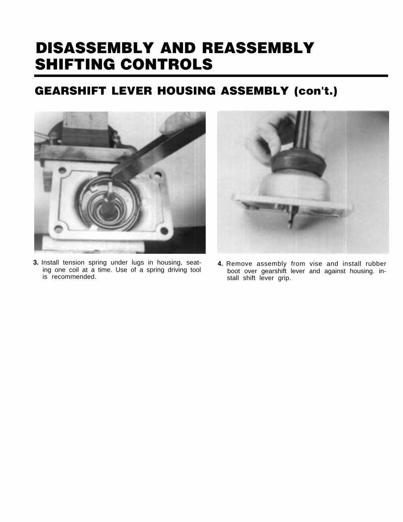
3. Install tension spring under lugs in housing, seat-ing one coil at a time. Use of a spring driving toolis recommended.
4. Remove assembly from vise and install rubberboot over gearshift lever and against housing. in-stall shift lever grip.

DISASSEMBLY AND REASSEMBLYSHIFTING CONTROLS
SHIFT BAR HOUSING ASSEMBLYA. Removal and Disassembly Round Rail Design
Cut 6229 B-10/88
Cut 5226 B-10/88

DISASSEMBLY AND REASSEMBLYSHIFTING CONTROLS
SHIFT BAR HOUSING ASSEMBLY (con't.)
1. Turn out capscrews and lift shift bar housing fromcase.
2. Remove the two tension plate capscrews, and thespring cover and gasket (inset).
3. Tilt the assembly and remove the four sets of ten-sion springs (inset) and balls from bores in top ofshift bar housing.
4. Lay shift bar housing on work bench as shown, re-move nine capscrews and three retaining plates(inset).

DISASSEMBLY AND REASSEMBLYSHIFTING CONTROLS
SHIFT BAR HOUSING ASSEMBLY (con'd.)
5. Remove the reverse yoke assembly from the shiftbar housing.
6. Remove the 1st-2nd yoke assembly from the shiftbar housing and remove the 1st-2nd interlock pin(inset), as shown.
7. Remove the 3rd-4th yoke assembly, and interlockpin (inset).
8. Remove the 5th-6th yoke assembly, and interlockpin (inset).

DISASSEMBLY AND REASSEMBLYSHIFTING CONTROLS
SHIFT BAR HOUSING ASSEMBLY (con'd.)
9. Remove the six interlock balls from the shiftbores of the shift bar housing.
(inset).
10. If it is necessary to replace yoke or shift blocks,secure shift rail in a vice equipped with brassjaws or wood blocks. Drive the retension/roll pinfrom yoke and yoke bar as shown.
11. If necessary the shift yoke bushings can be re-moved. Use pliers to bend the bushing tabsstraight then pull the bushings from the yoke slot
12. Loosen the neutral light switch/or plug. Removethe neutral light switch or plug and gasket fromthe housing (inset).

DISASSEMBLY AND REASSEMBLYSHIFTING CONTROLS
SHIFT BAR HOUSING ASSEMBLY (con't.)
13. Remove the pin from the neutral light switchbore. Note: The neutral light switch pin and thereverse light switch pin are not interchangeable.
14. Loosen the reverse light switch/or plug. Removethe light switch/or plug and gasket from thehousing (inset).
15. Remove the pin from the reverse light switchbore.
16. If the removal of reverse plunger is necessary, se-cure the shift rail and yoke in an Arbor press.
THE SNAP RING AND RETAINERPLATE ARE UNDER SPRINGTENSION.
Depress the reverse plunger spring and remove thesnap ring.
22

DISASSEMBLY AND REASSEMBLYSHIFTING CONTROLS
SHIFT BAR HOUSING ASSEMBLY (con't.)
17. Remove the retaining plate. 19. Remove the reverse plunger washer.
Remove the inner reverse plunger spring, then re-move the outer plunger spring (inset). Note: Thereverse and neutral plunger springs are not inter-changeable. Keep them separated.
20. Remove the reverse plunger.

DISASSEMBLY AND REASSEMBLYSHIFTING CONTROLS
SHIFT BAR HOUSING ASSEMBLY (con't.)
21. If the removal of neutral plunger is necessary, se-cure the 5th-6th shift yoke assembly in an Arborpress.
THE SNAP RING AND RETAINERPLATE ARE UNDER SPRINGTENSION.
Depress the neutral plunger spring and removesnap ring.
22. Remove the retaining plate.
23. Remove the neutral plunger spring. Note: The neu-tral and reverse plunger springs are not inter-changeable. Keep them separate.
24. Remove the neutral plunger.
DISASSEMBLY AND REASSEMBLYSHIFTING CONTROLS
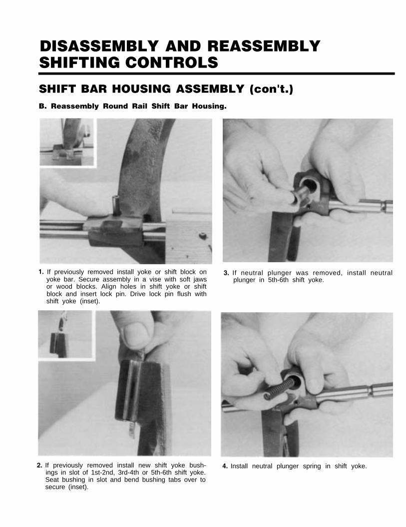
SHIFT BAR HOUSING ASSEMBLY (con't.)B. Reassembly Round Rail Shift Bar Housing.
1. If previously removed install yoke or shift block onyoke bar. Secure assembly in a vise with soft jawsor wood blocks. Align holes in shift yoke or shiftblock and insert lock pin. Drive lock pin flush withshift yoke (inset).
2. If previously removed install new shift yoke bush-ings in slot of 1st-2nd, 3rd-4th or 5th-6th shift yoke.Seat bushing in slot and bend bushing tabs over tosecure (inset).
3. If neutral plunger was removed, install neutralplunger in 5th-6th shift yoke.
4. Install neutral plunger spring in shift yoke.

DISASSEMBLY AND REASSEMBLYSHIFTING CONTROLS
SHIFT BAR HOUSING ASSEMBLY (con't.)
5. Install neutral retaining washer. 7. If reverse plunger was removed, install reverseplunger in reverse shift yoke.
THE SNAP RING AND RETAINERWILL BE UNDER SPRING TENSIONAS INSTALLED.
6. Place shift yoke in hand press. Depress retainingwasher and spring and install the snap ring.
8. Install reverse plunger washer.

DISASSEMBLY AND REASSEMBLYSHIFTING CONTROLS
SHIFT BAR HOUSING ASSEMBLY (con't.)
9. Install outer reverse plunger spring. Install inner re-verse plunger spring (inset).
10. Install reverse plunger retaining washer.
11. Place the shift yoke in a hand press. Depress re-taining washer and spring and install the snapring.
THE SNAP RING AND RETAINERWILL BE UNDER SPRING TENSIONAS INSTALLED.
12. Install the reverse light switch pin in the shift barhousing.

DISASSEMBLY AND REASSEMBLYSHIFTING CONTROLS
SHIFT BAR HOUSING ASSEMBLY (con't.)
13. Install reverse light switch or plug and gasket inshift bar housing. Tighten reverse light switch orplug (inset).
14. Install the neutral light switch pin in the shift barhousing.
15. Install the neutral light switch or plug and gasketin shift bar housing. Tighten neutral light switchor plug in shift bar housing (inset).
16. Install interlock balls in the shift bar housing inthe following sequence: position two interlockballs in the 1st-2nd crossbore; 3rd-4th crossbore;and the 5th-6th crossbore.

DISASSEMBLY AND REASSEMBLYSHIFTING CONTROLS
SHIFT BAR HOUSING ASSEMBLY (con't.)
17. Place shift bar housing on a work bench asshown, and install the reverse yoke assembly inposition as shown.
18. Install interlock pin in the 1st-2nd yoke assembly(inset). Position 1st-2nd yoke and rail assembly inshift bar housing.
19. Install interlock pin in the 3rd-4th yoke and rail as-sembly (inset). Position the assembly in shift barhousing.
20. Install interlock pin in the 5th-6th yoke assembly(inset). Position the assembly in shift bar housing.

DISASSEMBLY AND REASSEMBLYSHIFTING CONTROLS
SHIFT BAR HOUSING ASSEMBLY (con't.)
21. Make sure all yoke assemblies are in the neutralposition as shown (inset) and interlock pins arealigned to interlock ball crossbones.
22. Position the three retainer plates in shift barhousing.
23. Install nine capscrews in shift bar housing asshown and tighten to the recommended torque.
24. Position shift bar housing as shown and installfour interlock balls.

DISASSEMBLY AND REASSEMBLYSHIFTING CONTROLS
SHIFT BAR HOUSING ASSEMBLY (con't.)
25. Install the four interlock springs. 27. Install two capscrews and tighten to recom-mended torque.
26. Install gasket (inset) and retainer plate.
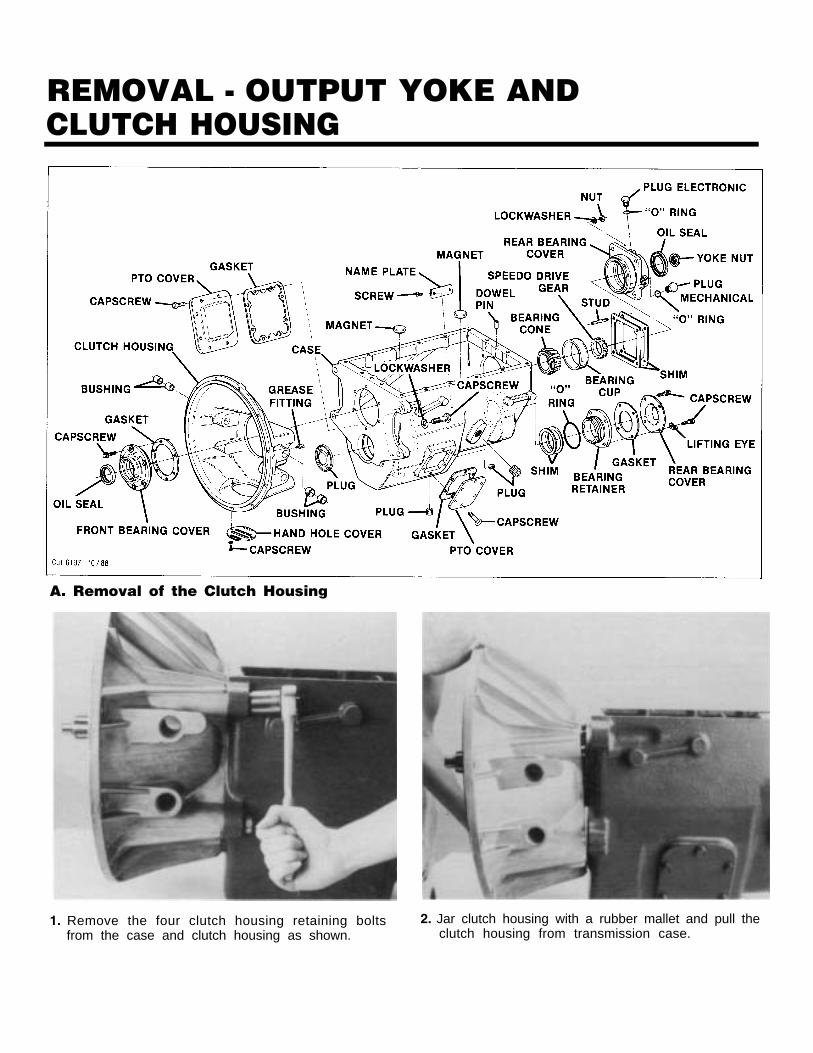
REMOVAL - OUTPUT YOKE ANDCLUTCH HOUSING
A. Removal of the Clutch Housing
1. Remove the four clutch housing retaining boltsfrom the case and clutch housing as shown.
2. Jar clutch housing with a rubber mallet and pull theclutch housing from transmission case.
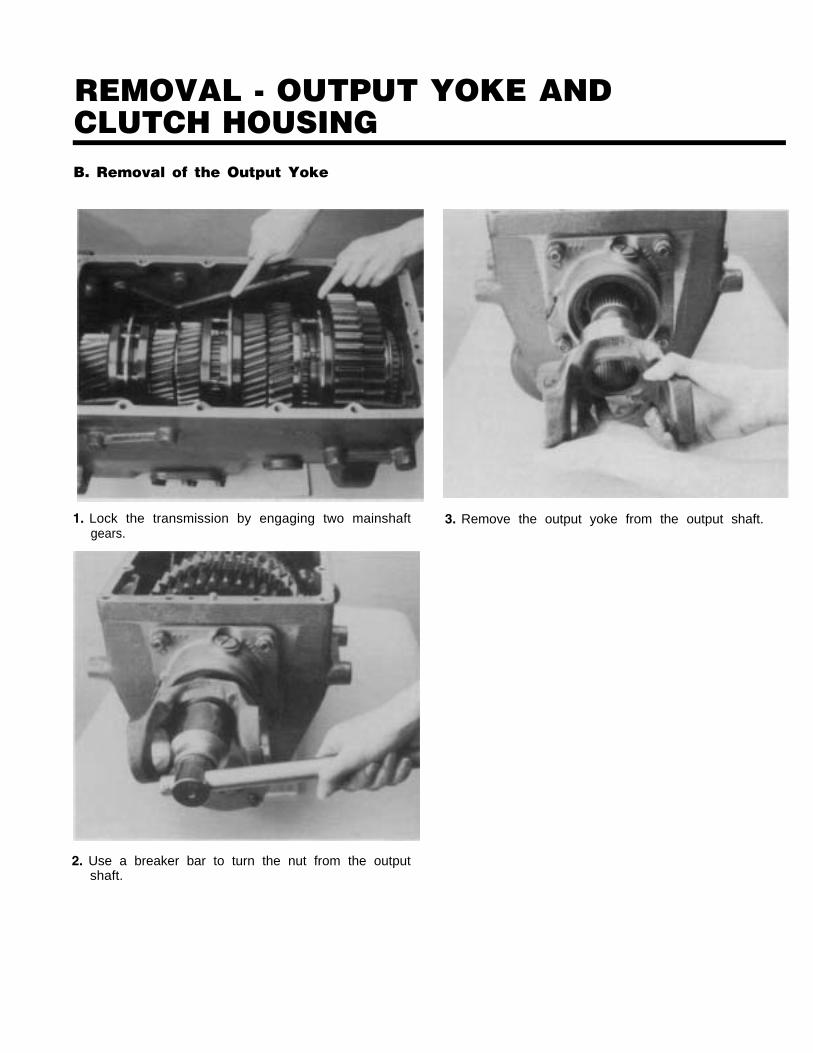
REMOVAL - OUTPUT YOKE ANDCLUTCH HOUSINGB. Removal of the Output Yoke
1. Lock the transmission by engaging two mainshaft 3. Remove the output yoke from the output shaft.gears.
2. Use a breaker bar to turn the nut from the outputshaft.

DISASSEMBLY - TRANSMISSIONA. Removal & Disassembly of the Input
Shaft Assembly
1. Turn out six capscrews, jar front bearing cover witha rubber mallet and remove. If necessary remove oilseal from cover (inset).
2. Remove input shaft assembly from transmission.
3. Using a chisel, remove bearing cage and rollers. in-stall bearing puller and remove bearing race frominput shaft.
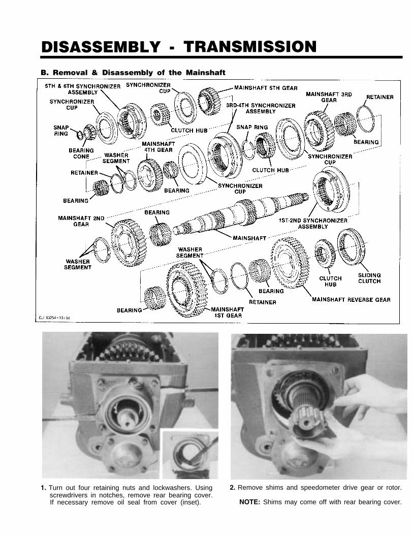
DISASSEMBLY - TRANSMISSIONB. Removal & Disassembly of the Mainshaft
1. Turn out four retaining nuts and lockwashers. Using 2. Remove shims and speedometer drive gear or rotor.screwdrivers in notches, remove rear bearing cover.If necessary remove oil seal from cover (inset). NOTE: Shims may come off with rear bearing cover.

DISASSEMBLY - TRANSMISSION
3.
4.
Wrap a sling around the 3rd-4th synchronizer as-sembly. Use a hoist to remove the mainshaft as-sembly from the case. Remove the reverse gearsliding clutch from the mainshaft (inset).
Install the mainshaft assembly in a vise equippedwith soft jaws or wood, front of shaft facing up. Re-move the 5th-6th speed synchronizer assembly andsynchronizer cups from the mainshaft.
5. Remove the retaining snap ring from front of of themainshaft (inset). Using a puller and clamp mountedbehind 5th-6th speed shift hub, remove the shift huband bearing.
Remove the 5th speed gear and bearings (inset) fromthe mainshaft.

DISASSEMBLY - TRANSMISSIONÑ Ñ . Ñ
7. Remove the split washer retaining ring and splitwashers from the mainshaft.
8. Remove the 4th speed gear and bearings from themainshaft.
9.
10.
Remove the 3rd-4th speed synchronizer assemblyand synchronizer cups from the mainshaft.
Remove the 3rd-4th speed shift hub retaining snapring from the mainshaft snap ring groove (inset).Remove the 3rd-4th speed shift hub from the main-shaft.

DISASSEMBLY - TRANSMISSION
11. Remove the 3rd speed gear from the mainshaft. Re-move the 3rd speed gear bearings from the main-shaft (inset).
12. Remove the split washer retaining ring and splitwashers from the mainshaft.
13. Remove 2nd speed gear and 2nd speed gearbearings from the mainshaft (inset).
14. Remove 1st-2nd speed synchronizer assembly fromthe mainshaft. Reposition the mainshaft in a vise,as shown, mainshaft rear facing up (inset).

DISASSEMBLY - TRANSMISSION
15. Using a gear puller and clamp around the reverseclutch hub, remove the reverse gear clutch hubfrom the mainshaft (inset).
DO NOT USE GEAR PULLER ONTHE 1ST OR REVERSE SPEED
GEAR. PULLING ON THESE GEARS WILL DAMAGETHE GEARS AND MAINSHAFT ASSEMBLY.
16. Remove the reverse gear and bearings (inset) fromthe mainshaft.
17. Remove the split washer retaining ring (inset), andthe split washers from the mainshaft.
18. Remove the 1st speed gear and bearings, from themainshaft.
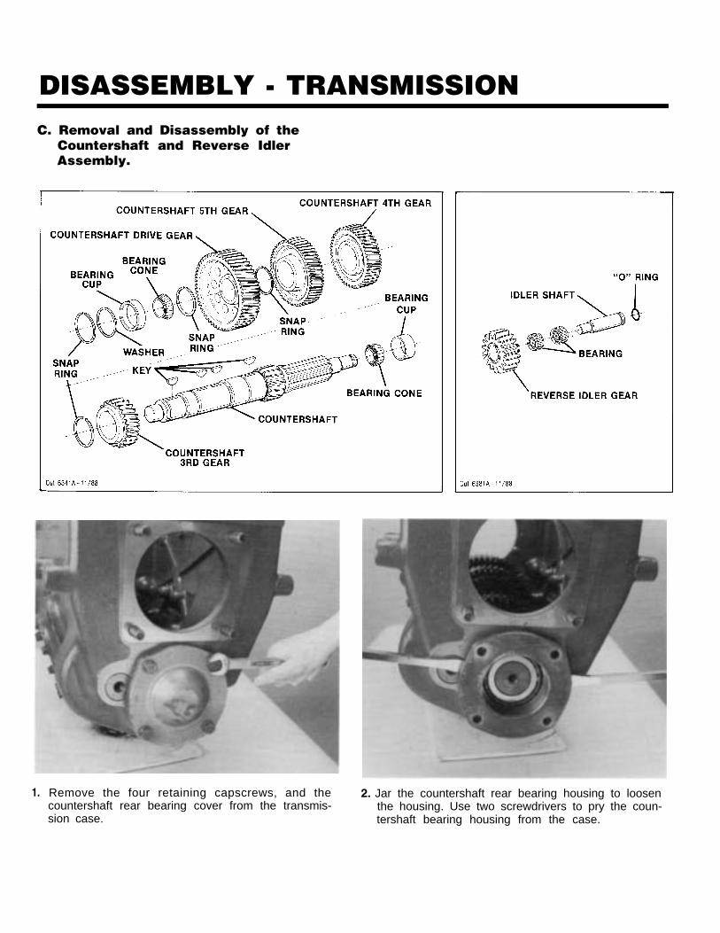
DISASSEMBLY - TRANSMISSIONC. Removal and Disassembly of the
Countershaft and Reverse IdlerAssembly.
1. Remove the four retaining capscrews, and the 2. Jar the countershaft rear bearing housing to loosencountershaft rear bearing cover from the transmis- the housing. Use two screwdrivers to pry the coun-sion case. tershaft bearing housing from the case.

DISASSEMBLY - TRANSMISSION
3. Remove the O-ring from the O-ring groove in thecountershaft rear bearing housing.
5. Remove the countershaft rear bearing outer racefrom the countershaft bearing case bore. The coun-tershaft assembly can be moved to the transmissionrear to assist removal of the rear bearing outer race.
4. Remove the countershaft rear bearing shims fromthe countershaft bearing case bore.
6. Using a slide hammer remove the reverse idler shaftfrom the case. Remove the O-ring from the O.D. ofthe reverse idler shaft (inset).

DISASSEMBLY - TRANSMISSION
7. Remove the reverse idler and two reverse idlerbearings from the transmission case.
9. If the countershaft front bearing race is to be re-placed, drive the countershaft front bore plugthrough the transmission front as shown.
THIS PROCEDURE WILL DAMAGETHE COUNTERSHAFT FRONT BOARE
PLUG. REPLACE THE BORE PLUG WITH A NEWPLUG UPON REASSEMABLY TO PREVENT OILLEAKAGE.
8. Move the countershaft assembly to case rear and liftthe countershaft, assembly from the transmissioncase.
countershaft bearing race to the case rear asshown.
NOTE: If a driver has to be used to drive the coun-tershaft front bearing race from the case BE CAU-TIOUS NOT TO DAMAGE the front race bore.
10. Remove the countershaft front bearing race retain-ing snap ring from the case snap ring groove (in-set). Remove the retaining snap ring and the

DISASSEMBLY - TRANSMISSION
11. Using a snap ring pliers and screwdriver move thefront countershaft retaining snap ring from thesnap ring groove and against the front countershaftbearing.
THE SNAP RING MUST BE COM-PLETELY OUT OF THE SNAP RING
GROOVE TO PREVENT DAMAGE TO THE COUNTER-SHAFT GEAR DURING REMOVAL.
12. Use a puller to remove the countershaft rearbearing from the countershaft rear.
13.
14.
Use the rear face of the countershaft drive gear asa base, then press the countershaft drive gear, frontcountershaft bearing and snap ring from the coun-tershaft assembly.
Remove the drive gear location key from the coun-tershaft.

DISASSEMBLY - TRANSMISSION
15. Using the rear face of 5th speed gear as a base,press it from the countershaft.
17. Remove 4th speed gear key (inset) and spacer fromcountershaft.
16. Remove the 5th speed gear key from shaft (inset).Using the rear face of 4th speed gear as a base,press it from the countershaft.
18. Use the rear face of the 3rd speed gear as a base,then press it from the shaft. If necessary, remove3rd speed gear key from shaft.

REASSEMBLY - TRANSMISSIONA. Reassembly and Installation of the
Countershaft Assembly
1. If previously removed, install 3rd speed gear key, 2. Install spacer and 4th and 5th countershaft key (in-Align keyway of gear with key in countershaft and set). Align keyway of gear to key in countershaftpress 3rd speed gear on shaft, long hub of gear to and press 4th speed gear on shaft, long hub of gearfront of countershaft. to the rear.

REASSEMBLY - TRANSMISSION
3. Align keyway of 5th speed gear to key on shaft.Press 5th gear on, long hub of gear to the front of,the countershaft.
4. Install spacer and drive gear countershaft key (inset).Align keyway of gear to key in countershaft andpress drive gear on shaft, long hub of gear to therear.
5. Install snap ring in groove at front of countershaft.

REASSEMBLY - TRANSMISSION
6. Using the proper size bearing driver, install the count-tershaft front bearing on the countershaft front.
7. Using the proper size bearing driver, install the coun-tershaft rear bearing on the countershaft rear. Makesure the bearing is seated against the countershaft.
8. If previously removed, install the countershaft frontbearing race snap ring in the case.
9. With the proper size bearing driver, install the coun-tershaft front bearing race in the countershaft frontbearing bore and against the retaining snap ring.

REASSEMBLY - TRANSMISSIONDO NOT REPLACE A DAMAGED,BENT, OR DENTED COUNTER.
SHAFT FRONT BORE PLUG. USE A NEW BORE PLUGTO PREVENT OIL LEAKAGE.
10. If previously removed, coat the outer diameter ofthe countershaft front bore plug with Loctite #510.Using a bearing driver, carefully drive the bore pluginto the transmission case. The outer diameterbore plug lip should be even with the transmissioncase front. Make sure the bore plug is not cockedin the bearing bore.
11. Carefully lower the countershaft assembly into thecase. Do not seat the countershaft in the frontbearing race. Let the rear of the countershaft ex-tend out the countershaft rear bearing bore, to aidin the installation of the reverse idler gear.
12. Install a new O-ring in the reverse idler shaft O-ringgroove.
13. Install the reverse idler gear bearings in the I.D. ofthe reverse idler gear.
REASSEMBLY - TRANSMISSION
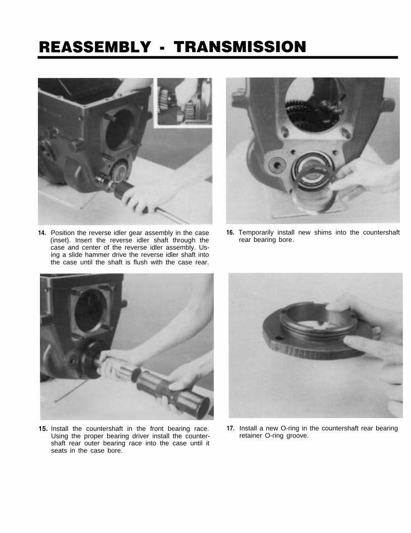
14. Position the reverse idler gear assembly in the case(inset). Insert the reverse idler shaft through thecase and center of the reverse idler assembly. Us-ing a slide hammer drive the reverse idler shaft intothe case until the shaft is flush with the case rear.
15. Install the countershaft in the front bearing race.Using the proper bearing driver install the counter-shaft rear outer bearing race into the case until itseats in the case bore.
16.
17.
Temporarily install new shims into the countershaftrear bearing bore.
Install a new O-ring in the countershaft rear bearingretainer O-ring groove.
REASSEMBLY - TRANSMISSION
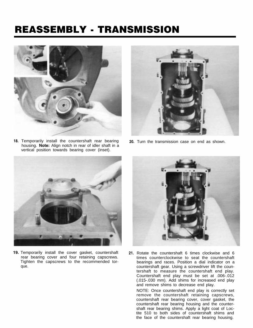
18. Temporarily install the countershaft rear bearinghousing. Note: Align notch in rear of idler shaft in avertical position towards bearing cover (inset).
19. Temporarily install the cover gasket, countershaftrear bearing cover and four retaining capscrews.Tighten the capscrews to the recommended tor-que.
20.
21.
Turn the transmission case on end as shown.
Rotate the countershaft 6 times clockwise and 6times counterclockwise to seat the countershaftbearings and races. Position a dial indicator on acountershaft gear. Using a screwdriver lift the coun-tershaft to measure the countershaft end play.Countershaft end play must be set at .006-.012(.015-.030 mm). Add shims for increased end playand remove shims to decrease end play.NOTE: Once countershaft end play is correctly setremove the countershaft retaining capscrews,countershaft rear bearing cover, cover gasket, thecountershaft rear bearing housing and the counter-shaft rear bearing shims. Apply a light coat of Loc-tite 510 to both sides of countershaft shims andthe face of the countershaft rear bearing housing.

REASSEMBLY - TRANSMISSION
22. Align notch in rear of idler shaft in a vertical posi-tion towards rear bearing cover (inset). Reinstall thecountershaft rear bearing, shims, countershaft rearbearing housing, cover gasket, countershaft rearbearing cover, and four retaining capscrews.Tighten the capscrews to the recommendedtorque.

REASSEMBLY - TRANSMISSIONB. Reassembly and Installation
of the Mainshaft Assembly
1. Install the mainshaft in a vise equipped with woodor soft jaws, mainshaft rear facing up. Lubricateand install 1st speed gear bearings (inset). Install1st speed gear with clutching teeth facing down.
2. Install the two split washers in groove of mainshaft,aligning the internal tangs of the split washers withthe machined slot in the groove of the mainshaft.
3. Install the split washer retaining ring over the splitwashers.
4. Lubricate and install the reverse gear bearings onthe mainshaft (inset). Install mainshaft reverse gearon the mainshaft with clutching teeth facing up.

REASSEMBLY - TRANSMISSION
5. Install the reverse gear clutch hub on the mainshaft,with the tapered threaded end facing up.
6. Using a heat lamp or hot plate and oil, heat themainshaft rear tapered bearing and install the ta-pered bearing on the mainshaft as shown. Makesure the bearing is seated on the reverse gear clutchhub.
7.
8.
Reposition the mainshaft in the vise with the main-shaft front facing up. Lubricate the mainshaft 1st -2nd speed synchronizer rings and install the 1st -2nd speed synchronizer with the synchronizer ringmarked FRONT facing up.
Lubricate and install the 2nd speed bearings (inset).Install the 2nd speed mainshaft gear on the main-shaft with clutching teeth facing down.
NOTE: DO NOT HEAT THE TAPERED BEARINGABOVE 275oF (136oC).

REASSEMBLY - TRANSMISSION
9. Install the two split washers in the mainshaft splitwasher grooves (inset). Install the split washer re-taining ring over the split washers.
10. Lubricate and install the mainshaft 3rd speedbearings on the mainshaft (inset). Install mainshaft3rd speed gear on the mainshaft clutching teethfacing up.
11. Lubricate the 3rd-4th speed shift hub and installthe shift hub on the mainshaft splines with the flatside of the shift hub facing up.
12. Install the 3rd-4th speed shift hub retaining snapring in the mainshaft snap ring groove.

REASSEMBLY - TRANSMISSION
13. Lubricate and install the 3rd speed synchronizercup on the mainshaft (inset). Lubricate and installthe 3rd - 4th speed synchronizer and synchronizercup, synchronizer ring identified FRONT facing up.
14. Lubricate and install the 4th speed bearings on themainshaft (inset). Install the 4th speed gear on themainshaft clutching teeth facing down.
15. Install the two split washers in the mainshaft splitwasher grooves (inset). Install the split washer re-taining ring over the split washers.
16. Lubricate and install the 5th speed bearings on themainshaft (inset). Install 5th speed gear on themainshaft clutching teeth facing up.

REASSEMBLY - TRANSMISSION
17. Install the 5th-6th speed clutch hub on the main-shaft splines with flat surface facing up.
19. Lubricate and install the 5th-6th speed synchroni-zer cups and synchronizer ring identified FRONTfacing up.
18. Using a heat lamp or hot plate and oil, heat themainshaft front tapered bearing and install thetapered bearing on the mainshaft as shown. Makesure the bearing is seated then install the main-shaft bearing retaining snap ring in the mainshaftsnap ring groove (inset).
20. Remove the mainshaft assembly from the vise andplace the assembly on a bench, install the reversegear sliding clutch (inset), and shift the 3rd-4thspeed synchronizer into 4th speed gear position.
Note: Do not heat the tapered bearing above 275oF(136oC).

REASSEMBLY - TRANSMISSION
21. Using a sling around the 3rd-4th synchronizer care-fully Ôlower the mainshaft assembly into the case.Remove the sling and place the 3rd-4th synchroni-zer in neutral.
22. Using the proper size sleeve type driver install thefront tapered bearing on the input shaft.
23.
24.
Install the input shaft by aligning the clutchingteeth on the 5th-6th speed synchronizer and inputshaft clutching teeth.
Coat the outer diameter of the front bearing coveroil seal with a light coat of Loctite #510. Install theoil seal with a flanged driver. Install a new inputshaft bearing race in the front bearing cover (inset).

REASSEMBLY - TRANSMISSION
25. Install the front bearing cover and gasket, align thecover and gasket with the six capscrew holes inthe case. Install the six capscrews and tighten tothe recommended torque.
NOTE: The top of the front bearing cover is markedÒTOPÓfor proper installation.
26. Install the speedometer drive or rotor on the outputshaft.

REASSEMBLY - TRANSMISSION
27. If necessary install rear bearing race (inset). Tem-porarily install shims and rear bearing cover.Tighten nuts to 60-70 lbs. ft. (81-95 Nm).
NOTE: Top of rear bearing cover is marked forproper installation,
Place transmission in a vertical position as shown.Install yoke and nut. Torque nut to 300-350 lbs. ft.(407-475 Nm). Rotate input shaft and mainshaft toseat bearings and races.
29. Position dial indicator as shown. Pry up on outputshaft to measure end play. End play must be set at.006-.010 (.152-.254 mm). Add shims for more endplay, remove shims for less end play.
NOTE: Once end play is correct remove yoke andrear bearing cover and apply a light coat of Loctite#510 to both sides of shims.
30. Install rear seal using a flanged driver.28.

REASSEMBLY - TRANSMISSION
31. Install the rear bearing cover on the 4 studs in thetransmission case. Install the four retaining nutsand washers, tighten to 60-70 lbs. ft. of torque.
NOTE: Top of the rear bearing cover is marked"TOP" for proper installation.

INSTALLATION - CLUTCH HOUSINGAND OUTPUT YOKEA. Installation of Clutch Housing
1. Position clutch housing on front of transmission.Install four retaining bolts and torque to therecommended torque.
B. Installation of Yoke
1. Lock the transmission by engaging two mainshaftgears (inset). Carefully install yoke and nut. Tightennut to the recommended torque.

INSTALLATION - SHIFTING CONTROLSA. Shift Bar Housing Assembly
1. Place transmission in neutral (inset) and installgasket on case. Place shift bar housing in neutraland install on case making sure shift yokes alignwith corresponding synchronizers and slidingclutch.
2. Apply Loctite #262 to threads of capscrews. Installcapscrews into housing and tighten to the recom-mended torque.

INSTALLATION - SHIFTING CONTROLSB. Gear Shift Lever Housing Assembly
1. With the shift bar housing in the neutral position,install gasket and gear shift lever assembly on theshift bar housing. Fit gear shift lever in correspond-ing finger assembly in bar housing as lever is in-stalled
2. Coat threads of retaining capscrews with Loctite#262 and install. Torque capscrews to 20-25 lbs. ft.(27-34 Nm).


METHOD OF PAYMENTORDERS UNDER $50.00 MUST INCLUDE PAYMENT.
PAYMENT ENCLOSED (U.S. FUNDS) MAKE CHECK PAYABLE TOEATON CORP.
CHECK # DATE AMT.
BILL ME AGAINST P.O. NO.
VISA OR MASTERCARD ORDERS EXP. DATE
ORDER MUST BE OVER $50.00
Qty. New Form No.PageNo.
Description TotalPrice
Price
Attention:INTERNATIONAL CUSTOMERS(including Canada)Literature orders may be subject to duty, taxes, andbrokerage fees. These fees are your responsibility.
*Shipping charges will be added tothe invoiced orders. Pre-paid orders
must include $8 shipping fee.
Bill To:CompanyNameTitleStreet Address
City/State ZipPhone: ( ) Ext:Fax Number:E-Mail Address:
Ship To: (if different from Bill To address)CompanyNameTitleStreet Address
City/State ZipPhone: ( ) Ext:
CardNumber
PLEASE SHIP MY ORDER VIA: (UNLESS OTHERWISE SPECIFIED,YOUR ORDER WILL SHIP REGULAR UPS OR PARCEL POST)
OTHER METHODS OF SHIPMENT ARE: 3-UPS SECOND DAY AIR2-UPS NEXT DAY AIR
PLEASE CIRCLE ONE OF THE ABOVE, IF NECESSARY.
OTHERS (PLEASE SPECIFY
Subtotal
Shipping*
TOTAL
Literature Services, Contract 4 / CA#1821750 Wallace Ave.St. Charles, IL 60174-3404
Mail, fax, or phone your order.Fax: 800-553-9715 Phone: 888-ETN-INFO (386-4636)
International OrdersFax: 630-377-1753 Phone: 630-377-9738
Estimated UPS Ground Shipping Costs:
Add $8 shipping for all pre-paid orders. P.O. & creditcard orders will be charged actual shipping costs.
1 – 20 lbs. $ 8.0020 – 50 lbs. 30.00
100lbs. 60.00
**Orders consisting ONLY of sales literature are not subject to shipping charges.**

Roadranger Literature ServicesAttn: Contract 4 / CA#1821750 Wallace Ave.St. Charles, IL 60174-3404
PlaceFirst-Class
StampHere


Fo r spec’ing or service assistance, call 1-80 0-826-HELP (4357) 24 hours a day, 7 days a w eek (Mexico:
001-80 0-826-4357), for mo re time on the road. O r visit our w eb sit e at www .roadr ang er.com .
Eaton Corporation • Truc k Components Operations • P. O. Bo x 4013 • Kalamaz oo, MI 490 03 • U.S.A. • www .roadranger .com
Roadranger: Eaton, Dana and other trusted partner s providing the best products and services in the industry , ensuring more time on the road.
©20 07 Eaton Corporation · All rights reserved.Pr inted in US A
Copyright Eaton and Dana Corporation,2007. EATON AND DANA CORPORA TIONhereby grants its customer s, vendor s, ordistributor s permission to freely copy,reproduce and/or distribute this documentin printed format. It may be copied only in itsentirety without any changes or modifications.THIS INFORMATION IS NOT INTENDEDFOR SALE OR RESALE, AND THIS NOTICEMUST REMAIN ON ALL COPIES.