service manual - filtres spa · gfci flow chart 4 service manual sc-cf ce & as service manual...
TRANSCRIPT

SERVICE MANUALSC-CF CE & AS SPA SYSTEMS TROUBLESHOOTING
VISUAL STEP- BY-STEP GUIDE & MORE!
TAKING OVER THE WAVES!
CLEARLY ADVANCED SPA SYSTEMS!™

Table of Contents
PreliminaryRequired Material 3Keypads 4
MiscellaneousParts List 60Wiring Diagram 61Professional Repair Kit 62
How toReplace The Spa Pack 55Adjust The Pressure Switch 58
TroubleshootingNothing Works! 35Spa Is Not Heating! 37Pump 1 Does Not Work! 41Pump 2 (or Blower) Does Not Work! 45Spa Light Does Not Work! 49Ozonator Does Not Work! 51Keys Do Not Work! 53
ProgrammingJumper Positions 8
Power & Ground CheckGFCI 5Electrical Wiring 6GFCI Trips! 7
Error Conditions3 Flashing Dots Appearing On Keypad Display 93 Flashing Dots & LED Displayed 13Display Is Flashing 17Wrong Temperature Appearing On Keypad Display 21FLO 23FLC 27Prr 29HL (OH) 31

Important Safety Information
WARNING: Risk of electrical shock! All procedures described in this service manual must only be performed by qualified personnel, in accordance with the standards applicable in the country of installation and, whenever possible, with the equipment powered off. When connecting the equipment, always refer to the wiring diagram affixed to the inside of your spa pack’s power box cover. This diagram always prevails over the wiring diagram at the end of this manual.
All information given subject to technical modifications without notice.
In order to be as helpful as possible, most sections of this manual were written in two distinct formats: problem-solving solutions are described using both troubleshooting flow charts and step-by-step procedures.
They should be used in conjunction, flow charts giving a global overview of specific problems while step-by-step procedures are more detailed.
Although this manual has been prepared with great care, some information may seem erroneous or unclear to you. In this case, please do not hesitate to contact us with your remarks or questions.

Pack Parts:
PliersPhillips & flat screwdrivers11/32" (M8) nut driver1/4" (M6) open-end wrench
3/8" (M10) open-end wrenchJumper cableMultimeterGFCI tester & digital thermometer (optional)
KeypadSC-CF system board (or complete spa pack)
Required MaterialThe tools, test equipment and components needed to carry out SC-CFSpa Pack service calls.
Tools & Test Equipment:
FusesTemperature probeHi-limit sensorPressure switch
Notes: The equipment delivered may slightly differ from the illustrations shown in this manual.
Spa Builders Systems Group sells Professional Repair Kits that include everything needed for SC-CF Spa Pack servicing. For more information, go to the last page of this manual.

KeypadsSC-CF single-pump and dual-pump systems are available with several types of keypads.
Described procedures and instructions apply to SC-CF systems equipped with one of the following keypads. For convenience purposes, the K-9 model will be used throughout this manual to illustrate specific actions to be performed.
Please note that key location can vary from one software to another. Refer to the Spa Pack Quick Reference Card (QRC) if needed.
K-18 model (127 mm x 63 mm)
K-9 model (114 mm x 51 mm)
K-19 model (177 mm x 82 mm)
4 Service Manual SC-CF CE & AS 5Service Manual SC-CF CE & AS

If GFCI trips, follow Troubleshooting Flow Chart below to identifythe problem:
Is GFCIproperly
connected?
If GFCI isstill tripping,disconnect
power inputwires.
Is GFCI stilltripping?
ReplaceGFCI.
ReplaceSpa Pack.
The cableis defective.
Call anelectrician!
Reconnectone component
at a timeuntil GFCI
starts tripping.
Replacedefective
component.
Verify GFCI wiringdiagram &
reconnect it.
yes
yes no
no
yes no
Disconnect all outputs,
including the two heater
blades & the light cord.
Is GFCI still tripping?
GFCI Flow Chart
4 Service Manual SC-CF CE & AS 5Service Manual SC-CF CE & AS

Note: For systems manufactured before 1999, if P33 & P34 are missing, install a 4-mm dia. cable between Line 1 and Line 2.
1 x 230 VAC (32 A) input supply wiring
Correct wiring of the electrical service box, GFCI and spa pack terminal block is essential.
• Make a visual inspection for signs of miswiring. Refer to the supplied wiring diagram. Call an electrician if necessary.
Electrical Wiring
Jumper JMP1 set in "HC" mode!
Note: For systems manufactured before 1999, if P33 & P34 are missing, install a 4-mm dia. cable between Line 1 and Line 2.
1 x 230 VAC (16 A) input supply wiring
Jumper JMP1 set in "LC" mode!
2 x 230 VAC (2 x 16 A) input supply wiringNOT ALLOWED IN AUSTRALIA
INPUTCABLE
LINE
GROUND
LINE 1
NEUTRAL
LINE 2
NEUTRAL
USE OP-TIONALJUMPERP34
P33
LINE
GROUND
LINE 1
NEUTRAL
LINE 2
NEUTRAL
INPUTCABLE
USE OP-TIONALJUMPERP34
P33
INPUTCABLE
INPUTCABLE
NEUTRALNEUTRAL
LINE 2
LINE 1NEUTRAL
LINE
LINE
6 Service Manual SC-CF CE & AS 7Service Manual SC-CF CE & AS

GFCI Trips!
1• Verify if GFCI is properly connected.
2• If it is not, verify GFCI wiring diagram and reconnect it.
If the equipment is connected but nothing seems to work, the power supply must be defective. Perform the following:
Note that in new installations, GFCI trippings due to miswiring are very common.
If breaker is properly wired, GFCI trippings can occur when the total amount of currentdrawn by the spa exceeds the rating of the breaker. Such an occurrence, however, is very unlikely since each output of the spa pack is individually fused and fuses will blow beforeGFCI trips.
A current leak to the ground will also make GFCI trip. If one of the components is faultyand there is a leak of more than 5 mA, GFCI will trip to prevent electrocution.
3• If GFCI is properly connected but still tripping,disconnectall outputs,including thetwo heaterblades & thelight cord.
4• If it stops tripping, reconnect onecomponent at a time until GFCIstarts tripping again. Then replacethe defective component.
5• If problem is still not solved, discon-nect the power input wires on theboard.
If GFCI still trips, the cable must bedefective.
Call an electrician!
6• If GFCI stops tripping, replace it.
7• If GFCI is still tripping, replace SpaPack.
6 Service Manual SC-CF CE & AS 7Service Manual SC-CF CE & AS

Jumper Positions
2• To change a setting, simply pull cover off and replace in desired position.
Certain parameters can be modified by changing the position of jumpers on the board.
To access jumpers, first remove SC-CF power box cover.
In some cases, jumper functions may differ from the following. Please check wiring diagramon power pack box cover to verify specific functions for your pack.
1• Jumpers are located in the lower right section of the board.
Position 2Position 1
Jumper location
Jumper JMP1: Current Limiting Option
This jumper is used to limit the current drawn when the two pumps are activated simultaneously.
Position 1 (HC): High Current mode. No current restriction.
Position 2 (LC): Low Current mode. The heater may not be turnedon if pump is on at high speed. Factory default setting.
Jumper JMP2: Temperature Display Unit
Position 1: Temperature will be displayed in degrees Fahrenheit (ºF).Factory default setting.
Position 2: Temperature will be displayed in degrees Celsius (ºC).
Jumper JMP3: Pump
Position 1: Single-pump system. Factory default setting.
Position 2: Dual-pump (or pump & blower) system.
8 Service Manual SC-CF CE & AS 9Service Manual SC-CF CE & AS

Flashing Dots Flow ChartIf 3 flashing dots appear on keypad display, follow Troubleshooting Flow Chart below to identify the problem:
3 flashing dots appear on the display!
Remove pack cover.
Is board LED on?Follow
flashing dots& LED flow chart.
yes no
Make sure jumper isset properly forcirculation pump(if present) andreset breaker.
Start Pump 1 (orcirculation pump if installed
by increasing set point).
Replace pressureswitch if problem
persists.
Do you havecontinuity on your
voltmeter forpressure switch?
yes no
Short pressureswitch terminals
with a jumper cable.
Replace pressureswitch cable
(if replaceable).
Replace pressureswitch cable
(if replaceable).
Remove anythingobstructing filter canisteror piping. Clear any air
locks. Verify water valves.
Try to adjustpressure switch.
Are dots stillflashing on
keypad display?
If problem persists,replace Spa Pack.
yes no
Verifypressureswitch
connection.
Try to adjustpressure switch.
Disconnectpressure switchfor 5 seconds
and reconnect it.
Are dots stillflashing on
keypad display?
If problem persists,replace Spa Pack.
yes no
Replace pressureswitch if problem
persists.
8 Service Manual SC-CF CE & AS 9Service Manual SC-CF CE & AS

Flashing Dots DisplayedThree flashing dots error condition indicates a pressure switch problem.
There must be enough water in the spa for normal operations. System may detect errorcondition if spa filter is dirty or if something restricts flow of water in piping.
The heater will automatically shut down when error condition occurs.
Power may remain On when the following steps are carried out.
5• If you do not detect continuity,verify if pressure switch cable isproperly connected to pressureswitch and board.
1• Make sure jumper is set pro-perly for circulation pump (ifpresent). See jumper settingsfor more details (p.8).
2• Verify if Pump 1 (or circulationpump if installed) is working. Ifpump is not working right, referto pump section of this manual.
3• If Pump 1 is working properly,turn it on by pressing Pump 1key (or start circulation pumpby increasing the set point) andtest continuity on pressure switch.
4• If you detect continuity, go tostep #10.
10 Service Manual SC-CF CE & AS 11Service Manual SC-CF CE & AS

Flashing Dots Displayed
6• Ensure adequate water flow inthe heater and short two pres-sure switch terminals with jumpercable.
7• If the three dots disappear, firstmake sure there is no blockageof water or air lock and checkwater valves.
If the installation is older than 2years, replace pressure switchand recalibrate it.
If installation is recent, try read-justing the pressure switch. If thisis not possible, replace switch.
(Refer to "How to Adjust thePressure Switch" section of thismanual.)
8• If the three dots still appear,the problem may be either withswitch cable or board.
Remove plastic cover and re-place cable (if replaceable).
9• Replace Spa Pack if error con-dition still persists. (Refer to "Howto Replace the Spa Pack" sectionof this manual.)
10 Service Manual SC-CF CE & AS 11Service Manual SC-CF CE & AS
Flashing Dots Displayed
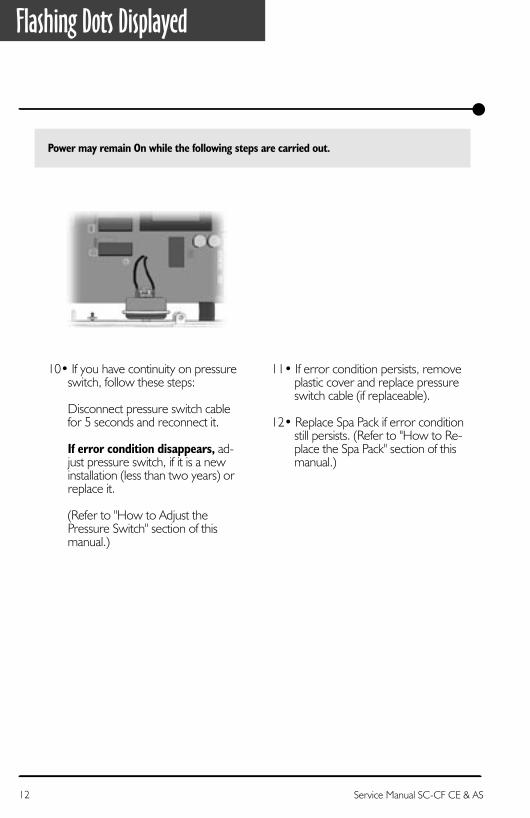
Power may remain On while the following steps are carried out.
11• If error condition persists, remove plastic cover and replace pressure switch cable (if replaceable).
12• Replace Spa Pack if error condition still persists. (Refer to "How to Re- place the Spa Pack" section of this manual.)
10• If you have continuity on pressureswitch, follow these steps:
Disconnect pressure switch cablefor 5 seconds and reconnect it.
If error condition disappears, ad-just pressure switch, if it is a newinstallation (less than two years) orreplace it.
(Refer to "How to Adjust thePressure Switch" section of thismanual.)
12 Service Manual SC-CF CE & AS 13Service Manual SC-CF CE & AS

Flashing dots & LED Flow Chart
Take water temperaturewith a digital thermometer.
Are you getting correctwater temp. reading on the display?
yes no
Replace Spa Packif error condition
still persists.
Verify iftemperature probe
is properly connected.
If so, replace probeand reset breaker.
Verify iftemperature probeis touching wateror if cold air from
back can affectreading.
Is HL probeproperly connected(verify probe only
if replaceable)?
Clean pins,reconnect
it, and resetthe breaker.
Verify if anythingis obstructing waterflow (closed traps or
dirty filters).
If error conditionpersists, replace probe
(if replaceable)and reset breaker.
When errorcondition occurs,
does heaterbarrel feel hot?
yes no
If error condition stillpersists, replace Spa Pack.
Turn breaker off then on again to reset the system.If Hi-Limit condition no longer persists, check for blockage
of water in the piping.
If error condition occurs (potential Hi-Limit sensor or temperature probe problem), follow Troubleshooting Flow Chart below to identify the problem:
12 Service Manual SC-CF CE & AS 13Service Manual SC-CF CE & AS

Flashing Dots & LED Displayed
Turn breaker off then on again to reset the system.
If 3 flashing dots and LED disappear, wait until they are displayed again on keypad.
Power may remain On.
c- If error condition persists, re-place probe (if replaceable only)and reset breaker.
d- If problem is not solved, replaceSpa Pack. (Refer to "How to Re-place the Spa Pack" section of thismanual.)
3• Proceed to following page if key-pad display shows incorrect tem-perature.
1• Take water temperature with adigital thermometer.
2• If keypad display shows correcttemperature:
a- Check if heater barrel feels hot.
If it's hot, verify if anything is obstructing the flow of water(closed valves or dirty filter).
b- If it's not, verify if hi-limit probeis properly connected (checkprobe only if replaceable).
Try to clean probe connectorpins. Even a small coating of filmmay cause a bad connection.Reconnect probe and resetbreaker.
The three flashing dots and LED error condition is related to the Hi-Limit sensor or temperature probe.
14 Service Manual SC-CF CE & AS 15Service Manual SC-CF CE & AS
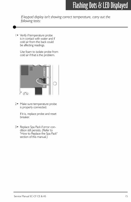
Flashing Dots & LED DisplayedIf keypad display isn't showing correct temperature, carry out thefollowing tests:
2• Make sure temperature probeis properly connected.
If it is, replace probe and resetbreaker.
3• Replace Spa Pack if error con-dition still persists. (Refer to"How to Replace the Spa Pack"section of this manual.)
1• Verify if temperature probeis in contact with water and ifcold air from the back couldbe affecting readings.
Use foam to isolate probe fromcold air if that is the problem.
14 Service Manual SC-CF CE & AS 15Service Manual SC-CF CE & AS

16 Service Manual SC-CF CE & AS 17Service Manual SC-CF CE & AS

Display Flashing Flow ChartOn certain packs, if system detects temperature at 44°C (112°F) or higher, the display will start flashing. Follow Troubleshooting Flow Chart below to identify the problem:
Are you getting correctwater temp. reading on the display?
ReplaceSpa Pack ifproblem
still persists.
Verify iftemperature probe
is properly connected.
If so, replace probeand reset breaker.
Verify iftemperature probeis touching wateror if cold air from
back can affectreading.
Removespa cover
(even duringthe night).
Startblower, if
spa isequippedwith one.
Wait untilspa cools
down (addcold waterif needed).
Pump isoverheatingwater duringfilter cycle.
Lowerfilter cycleduration.
ReplaceSpa Pack.
Lower set pointbelow actual
temperature ofwater.
"Heater" indicatoron keypad displayshould disappear.
Do you get a240 VAC reading
betweentwo heater wires
on the board?
yes no
Is weathervery hot?
yes no
yes no
A power failurehas occurred.
Systemworks fine.
Pressany key.
Has displaystopped flashing?
yes no
16 Service Manual SC-CF CE & AS 17Service Manual SC-CF CE & AS

Display Is FlashingIf digital thermometer water temperature reading is 44°C (112°F) or higher and keypad display indicates correct temperature, carry out the following tests:
If display stops flashing after pressing a key, this means that a power failure has occurred.System works fine.
If weather is very hot:
1• Remove spa cover (even duringthe night). Start blower if spa isequipped with one. Wait untilspa cools down (add cold waterif necessary).
If hot weather is not a factor:
2• Lower set point below currentwater temperature.
"Heater" indicator should disappearfrom keypad display.
4• If you do not read 240 VAC, pumpmay be overheating water duringfilter cycle.
Enter Programming mode andshorten filter cycle duration.
5• If you do read 240 VAC, test theelement. If it is opened, replaceit. If element works fine, replaceSpa Pack.
(Refer to "How to Replace theSpa Pack" section of this manual.)
3• Remove spa cover. With a volt-meter, read the voltage betweenthe two heater wires on the board.
18 Service Manual SC-CF CE & AS 19Service Manual SC-CF CE & AS
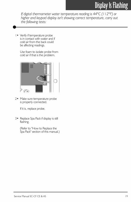
Display Is FlashingIf digital thermometer water temperature reading is 44°C (112°F) or higher and keypad display isn't showing correct temperature, carry out the following tests:
2• Make sure temperature probeis properly connected.
If it is, replace probe.
3• Replace Spa Pack if display is stillflashing.
(Refer to "How to Replace theSpa Pack" section of this manual.)
1• Verify if temperature probeis in contact with water and ifcold air from the back couldbe affecting readings.
Use foam to isolate probe fromcold air if that is the problem.
18 Service Manual SC-CF CE & AS 19Service Manual SC-CF CE & AS

20 Service Manual SC-CF CE & AS 21Service Manual SC-CF CE & AS

Wrong Temperature Flow ChartOn certain packs, if system detects that temperature is not within normal limits, wrong temperature will be displayed. Follow Troubleshooting Flow Chart below to identify the problem:
Replace Spa Pack ifproblem persists.
Check if regulationprobe is properly connected.
Replace probe witha spare and verify ifproblem is solved.
If it is, replaceprobe with spare.
Unplug probe connectorand clean pins on the
board (even a small coatingof film may cause a bad
connection).Reconnect probe.
Make sure to use the right probe!Probe wires should be in this order:
or:
Black
Green
Red
PIN #1
PIN #4
20 Service Manual SC-CF CE & AS 21Service Manual SC-CF CE & AS

Wrong Temperature DisplayedWrong temperature on keypad display indicates a problem with regulation sensor. The system is constantly verifying if temperature probe reading iswithin normal limits.
Note that water temperature must be over 2°C (35°F) in order to carry out the following steps.Power can remain On.
1• Verify if regulation probe (sensorlocated in spa) is properly con-nected.
3• Reconnect probe.
If wrong temperature is stilldisplayed, replace probe witha spare and place probe headdirectly in spa water.
If problem is solved, replaceprobe.
4• Replace Spa Pack if problempersists.
2• Disconnect probe connectorand clean probe connector pins.Even a small coating of film maycause a bad connection.
22 Service Manual SC-CF CE & AS 23Service Manual SC-CF CE & AS

Is pumpworking?
Refer to "Pump notWorking" section.
Remove anythingobstructing filter.
Clear any air locksand verify water valves.
Verify ifpressure switchcable is properly
connected.
There must be adequate waterin spa for normal use.
yes no
Is anything limitingflow of water into pipes?
yes no
ReplaceSpa Pack.
Adjust or replacepressure switch.
Lower temperature set pointto 16°C (60°F) and turn pump off.
Short two pressure switch terminalswith a jumper cable.
Does FLC error condition appearon keypad display?
yes no
FLO Flow ChartIf FLO error condition occurs (problem with the pressure switch: pump is on but no water pressure detected), follow Troubleshooting Flow Chart below to identify the problem:
Replacepressure
switch cable(if replaceable).
22 Service Manual SC-CF CE & AS 23Service Manual SC-CF CE & AS

FLO Error Condition
Jumper location
An FLO error condition indicates a pressure switch problem. If system does not detect any pressure when pump is manually or automatically turned on, an FLO error condition will occur.
There must be enough water in the spa for normal operations. System may detect an FLOerror condition if spa filter is dirty or if something restricts flow of water in piping.
The heater will automatically shut down when an FLO error condition occurs.
Power may remain On when the following steps are carried out.
3• Verify if pressure switch cable is pro-perly connected to pressure switchand board.
1• Verify if pump is working. If pumpis not working properly, refer topump section of this manual.
2• Clean filter and check for air block-ages, closed trap valves or anythingthat could restrict flow of water inpiping.
24 Service Manual SC-CF CE & AS 25Service Manual SC-CF CE & AS
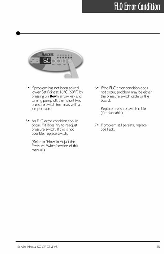
4• If problem has not been solved,lower Set Point at 16°C (60°F) bypressing on Down arrow key andturning pump off; then short twopressure switch terminals with ajumper cable.
5• An FLC error condition shouldoccur. If it does, try to readjust pressure switch. If this is not possible, replace switch.
(Refer to "How to Adjust thePressure Switch" section of thismanual.)
6• If the FLC error condition does not occur, problem may be either the pressure switch cable or theboard.
Replace pressure switch cable(if replaceable).
7• If problem still persists, replaceSpa Pack.
FLO Error Condition
24 Service Manual SC-CF CE & AS 25Service Manual SC-CF CE & AS

26 Service Manual SC-CF CE & AS 27Service Manual SC-CF CE & AS

Disconnectpressure switch cablefrom pressure switch.
Does FLO error conditionoccur when pump is on?
Adjustpressure switch.
Replacepressure switch
if FLC errorcondition
persists whenyou start orstop pump.
ReplaceSpa Pack.
yes no
FLC Flow ChartIf FLC error condition occurs (usually pressure switch problem - pump is off but water pressure is detected), follow Troubleshooting Flow Chart below to identify the problem:
Replacepressure switch
cable (if possible).
26 Service Manual SC-CF CE & AS 27Service Manual SC-CF CE & AS

FLC Error Condition
Power may remain On when the following steps are carried out.
2• If FLO error condition does notoccur, replace pressure switchcable (if possible).
3• replace Spa Pack.
1• Disconnect pressure switch cableon pressure switch.
If FLO error condition occurs whenpump is turned on, adjust pressureswitch.
If this is not possible, replace switch.
An FLC error condition indicates a pressure switch problem. If system detects any pressure when pump is off, an FLC error condition will occur.
28 Service Manual SC-CF CE & AS 29Service Manual SC-CF CE & AS
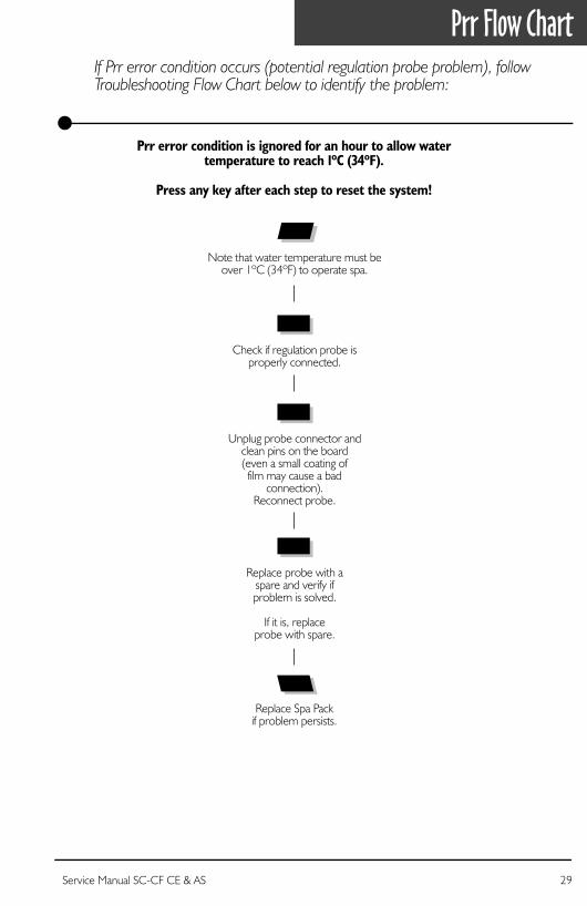
Prr error condition is ignored for an hour to allow watertemperature to reach 1ºC (34ºF).
Press any key after each step to reset the system!
If Prr error condition occurs (potential regulation probe problem), follow Troubleshooting Flow Chart below to identify the problem:
Replace Spa Packif problem persists.
Note that water temperature must beover 1ºC (34ºF) to operate spa.
Check if regulation probe isproperly connected.
Replace probe with aspare and verify ifproblem is solved.
If it is, replaceprobe with spare.
Unplug probe connector andclean pins on the board(even a small coating offilm may cause a bad
connection).Reconnect probe.
Prr Flow Chart
28 Service Manual SC-CF CE & AS 29Service Manual SC-CF CE & AS

Prr Error Condition
1• Verify if regulation probe is properlyconnected to the board.
3• Reconnect probe.
If Prr error condition still persists,replace probe with a spare andplace probe head directly in spawater.
If problem is solved, replaceprobe.
4• If problem persists, replace SpaPack.
2• Disconnect probe connector and clean probe connector pins. Evena small coating of film may cause abad connection.
Probeconnectorpins
The Prr error condition indicates a problem with regulation probe.The system is constantly verifying if temperature probe reading iswithin normal limits.
Prr error condition is ignored for an hour to allow water temperature to reach 1°C (34°F). Water temperature must be over 1°C (34°F) to carry out the following steps.
Press any key after each step to reset the system.
Power may remain On when the following steps are carried out.
30 Service Manual SC-CF CE & AS

Take water temperaturewith a digital thermometer.
Is water temperature44°C (112°F) or higher?
Are you getting correct watertemperature reading on the display?
Replace probeif HL (OH) error
condition stillpersists.
Verify if temperatureprobe is properly
connected.
Verify iftemperature probeis touching wateror if cold air fromback can affect its
reading.
Pump isoverheatingwater duringfilter cycle.
Lowerfilter cycleduration.
ReplaceSpa Pack.
Removespa cover
(even duringthe night).
Startblower,if spa is
equippedwith one.
Wait untilspa cools
down (addcold waterif needed).
yes no
Lower Set Pointbelow actual
water temperature.
"Heater" indicatoron keypad displayshould disappear.
Do you get a ≈240 VACreading between thetwo heater wires on
the board?
yes no
Is weathervery hot?
yes no
yes no
HL (OH) Flow ChartIf HL (OH) error condition occurs (potential hi-limit sensor or temperature probe), follow Troubleshooting Flow Chart below to identify the problem:
Switch GFCI off then on after each step to reset the system!
Steady message: Means system has shut down heater because water temperature at the heater has reached 48°C (119°F).Blinking message or OH: Means except for the Smart Winter Mode, system has shut down because water temperature in the spa has reached 44°C (112°F).
Unplug probeconnector andclean pins on
the board(even asmall coating offilm may cause
a bad connection).Reconnect probe.
If HL (OH) error condition persists,replace Spa Pack.
Clean filter andlook for air locks,
closed valves or anythingthat could restrict
water flow.
Verify if hi-limitprobe is properlyconnected. Try to
clean pins andreconnect
probe.
When HL (OH) errorcondition occurs,
does heaterbarrel feel hot?
yes noReplaceSpa
Pack if HL (OH)error condition
still persists.
30 Service Manual SC-CF CE & AS
HL (OH) Error Condition
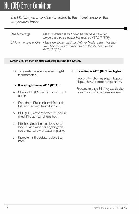
Switch GFCI off then on after each step to reset the system.
1• Take water temperature with digital thermometer.
2• If reading is below 44°C (112°F): a- Check if HL (OH) error condition still occurs.
b- If so, check if heater barrel feels cold. If it's cold, replace hi-limit sensor.
c- If HL (OH) error condition still occurs, check if heater barrel feels hot.
d- If it's hot, clean filter and look for air locks, closed valves or anything that could restrict flow of water in piping.
e- If problem still persists, replace Spa Pack.
The HL (OH) error condition is related to the hi-limit sensor or the temperature probe.
Steady message: Means system has shut down heater because water temperature at the heater has reached 48°C (119°F).
Blinking message or OH: Means except for the Smart Winter Mode, system has shut down because water temperature in the spa has reached
44°C (112°F).
3• If reading is 44°C (112°F) or higher:
Proceed to following page if keypad display shows correct temperature.
Proceed to page 34 if keypad display doesn't show correct temperature.
32 Service Manual SC-CF CE & AS 33Service Manual SC-CF CE & AS

If weather is very hot:
1• Remove spa cover (even during the night). Start blower if spa is equipped with one. Wait until spa cools down (add cold water if necessary).
If hot weather is not a factor:
2• Lower Set Point below current water temperature.
The "Heater" indicator should disappear from keypad display.
To shorten filter cycle duration:
5• Press and hold Light key for 5 seconds. The display shows the currently set filter cycle duration in hours.
Use Down arrow key to lower the number of hours: 0 = no filtration 12 = continuous filtration
When the desired value is dis- played, press Light key again. The filter cycle will start immediately.
(For more information on filter cycles, refer to the User's manual).
6• If you do read ≈240 VAC, replace Spa Pack.
3• With a voltmeter, read voltage between the two heater wires on the board.
4• If you do not read ≈240 VAC, pump may be overheating water during the filter cycle.
Shorten filter cycle duration.
HL (OH) Error ConditionIf digital thermometer water temperature reading is 44°C (112°F) or higher and keypad display indicates correct temperature, carry out the following tests.
32 Service Manual SC-CF CE & AS 33Service Manual SC-CF CE & AS

HL (OH) Error Condition
2• Make sure temperature probe is properly connected to the board.
3• Disconnect probe connector and clean probe connector pins. Even a small coating of film may cause a bad connection.
If it is, replace probe.
4• Replace Spa Pack if HL (OH) error condition still persists.
1• Verify if temperature probe is in contact with water and if cold air from the back could be affecting readings.
Use foam to isolate probe from cold air if that is the problem.
If digital thermometer water temperature reading is 44°C (112°F) or higher and keypad display isn't showing correct temperature, carry outthe following tests.
34 Service Manual SC-CF CE & AS 35Service Manual SC-CF CE & AS

Do you read ≈240 VACbetween Line 1 (L1) andneutral (N) and between
Line 2 (L2) and neutral (N)on the board?
Check state of thetransformer fuse (F4).
Is transformerfuse burnt ?
If nothingappears on
keypad display,replace Spa Pack.
The electricalwiring is
defective.
Call anelectrician!
yes no
"Nothing Works!" Flow ChartIf nothing seems to work, follow Troubleshooting Flow Chart below to identify the problem:
Replacetransformerfuse (F4).
Please notethat this fuseis a miswiringprotection.
Verify inputconnection
before poweringSpa Pack again.
Verify if keypadis properly connected.
All eight pins shouldbe properly plugged in
and the black wireoriented to the top.
Unplug keypad connectorand clean pins on the
board (even a small coatingof film may cause a bad
connection).Reconnect probe.
yes no
34 Service Manual SC-CF CE & AS 35Service Manual SC-CF CE & AS
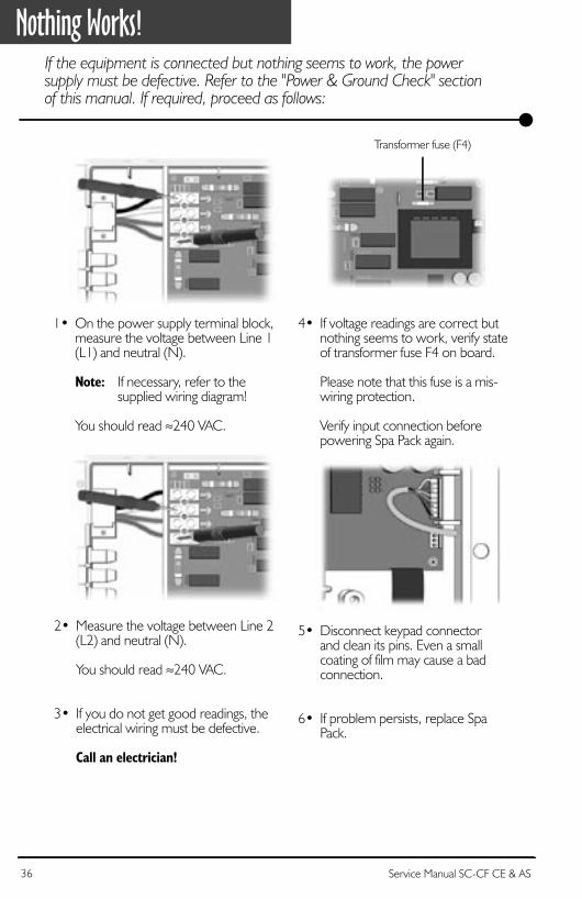
1• On the power supply terminal block, measure the voltage between Line 1 (L1) and neutral (N).
Note: If necessary, refer to thesupplied wiring diagram!
You should read ≈240 VAC.
4• If voltage readings are correct butnothing seems to work, verify stateof transformer fuse F4 on board.
Please note that this fuse is a mis-wiring protection.
Verify input connection beforepowering Spa Pack again.
5• Disconnect keypad connectorand clean its pins. Even a smallcoating of film may cause a badconnection.
6• If problem persists, replace SpaPack.
2• Measure the voltage between Line 2(L2) and neutral (N).
You should read ≈240 VAC.
3• If you do not get good readings, theelectrical wiring must be defective.
Call an electrician!
Nothing Works!If the equipment is connected but nothing seems to work, the power supply must be defective. Refer to the "Power & Ground Check" sectionof this manual. If required, proceed as follows:
Transformer fuse (F4)
36 Service Manual SC-CF CE & AS 37Service Manual SC-CF CE & AS

Any errorconditions
(3 flashing dots, etc.)displayed?
Refer to specificsection.
Make sure temperatureset point is higherthan current water
temperature.
Is "Heater"indicator on?
yes no
yes no
yes no
Take water temperatureand compare withtemperature valueon keypad display.
Is differencegreater than 1°C (2°F)?
Verify if temperatureprobe is touching
water or if hot air rearis affecting reading.
Isolate back ofprobe with foam.
Disconnect probeconnector and clean
probe connector pins.Even a small coatingof film may cause a
bad connection.
Replace keypad
ReplaceSpa Pack.
Replaceelement.
Problemsolved.
ReplaceSpa Pack.
yes no
Do you get a ≈240 VACreading betweenthe two heaterterminals onthe board?
Are heaternuts properly
connected to theelement?
Try tightening nutsto element.
Still not heating?
yes no
yes no
"Spa Not Heating!" Flow ChartIf the system does not seem to be heating the water, follow Troubleshooting Flow Chart below to identify the problem:
If problem persistreplace spa pack
Replacetemperature
probe.
36 Service Manual SC-CF CE & AS 37Service Manual SC-CF CE & AS
Spa Not Heating!
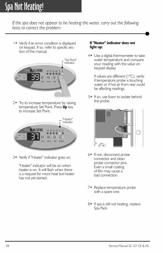
6• If not, disconnect probeconnector and cleanprobe connector pins.Even a small coatingof film may cause abad connection.
7• Replace temperature probewith a spare one.
8• If spa is still not heating, replaceSpa Pack.
If "Heater" indicator does notlight up:
2• Try to increase temperature by raisingtemperature Set Point. Press Up keyto increase Set Point.
1• Verify if an error condition is displayed on keypad. If so, refer to specific sec-tion of this manual.
"Set Point"indicator
4• Use a digital thermometer to takewater temperature and compareyour reading with the value onkeypad display.
If values are different (1°C), verifyif temperature probe is touchingwater or if hot air from rear couldbe affecting readings.
5• If so, use foam to isolate behindthe probe.
3• Verify if "Heater" indicator goes on.
"Heater" indicator will be on whenheater is on. It will flash when thereis a request for more heat but heaterhas not yet started.
"Heater"indicator
If the spa does not appear to be heating the water, carry out the following tests to correct the problem:
38 Service Manual SC-CF CE & AS 39Service Manual SC-CF CE & AS

1• Measure voltage between the twoheater screws on the board.
Replace Spa Pack if you are not get-ting a reading of ≈240 VAC.
2• If voltage reading is correct, verifyif heater nuts are properly connect-ed to the element.
If not, tighten the two heater nutsto the element.
3• If problem persists, replace theelement.
Spa Not Heating!If "Heater" indicator appears on the display, but spa is still not heating, carry out the following tests to correct the problem:
38 Service Manual SC-CF CE & AS 39Service Manual SC-CF CE & AS

40 Service Manual SC-CF CE & AS 41Service Manual SC-CF CE & AS

ReplacePump 1.
ReplaceSpa Pack.
Problemresolved.
ReplaceSpa Pack.
Replacekeypad.
Does "Pump 1" indicatorappear on keypad display
when you press Pump 1 key?
Is Pump 1 workingin either speed?
yes no
yes no
Measure voltage onthe board for both speeds.
Do you read ≈240 VACfor both speeds
to the pumpterminals on the
board?
yes no
ReplacePump 1 fuse (F1).
Does problem persist?
yes no
Pump 1 Flow ChartIf Pump 1 does not work, follow Troubleshooting Flow Chart below to identify the problem:
Is the displayflashing?
Refer tospecific section.
yes no
40 Service Manual SC-CF CE & AS 41Service Manual SC-CF CE & AS

Pump 1 Does Not Work!
3• If "Pump 1" indicator does not ap-pear, use a spare keypad to verify ifkeypad is defective.
If it is, replace defective keypad.
If not, replace Spa Pack.
2• Verify if "Pump 1" indicator appearson keypad display when you pressPump 1 key.
"Pump 1"indicator
If Pump 1 is not working, carry out the following tests to correct theproblem:
To increase the life of the relay, we use a "snubber" circuit on the pump relay. With this type of circuit, if no pump is connected to an output and relays are open, the voltmeter will continue reading around 60 V. This is normal.
It is important to measure voltage when pump is connected to pack.
4• If "Pump 1" indicator appearswhen Pump 1 key is pressed,verify if pump works in eitherspeed.
1• Check if the display is flashing. If so,refer to specific section.
42 Service Manual SC-CF CE & AS 43Service Manual SC-CF CE & AS

1• Replace Pump 1 fuse (F1).
2• If replacing the fuse is not effective orif Pump 1 works in only one speed,take voltage reading on the boardfor both speeds.
Turn Pump 1 to high speed and takevoltage reading between blue andbrown wire connectors (P7 & P12).
Your should read ≈240 VAC.
Note: If necessary, refer to thesupplied wiring diagram!
3• Turn Pump 1 to low speed andtake voltage reading betweenblue and black wire connectors(P7 & P14).
You should read ≈240 VAC.
4• If voltage reading is correct, re-place Pump 1.
5• If not, replace Spa Pack.
Pump 1 fuse (F1)
Pump 1 Does Not Work!If Pump 1 does not work in either speed, carry out the following tests to correct the problem:
42 Service Manual SC-CF CE & AS 43Service Manual SC-CF CE & AS

44 Service Manual SC-CF CE & AS 45Service Manual SC-CF CE & AS

Replace Pump 2or blower.
ReplaceSpa Pack.
Problemresolved.
System worksfine
Replacekeypad.
If still not working,replace Spa Pack.
Does "Pump 2" or"Blower" indicator
appear onkeypad displaywhen you press
Pump 2 orBlower key?
Is Pump 2 orblower working?
yes no
yes no
Measure voltageon the board.
Do you read ≈240 VACto the pump or blower
terminals onthe board?
yes no
Replace Pump 2or blower fuse (F2).
Does problem persist?
yes no
Verifyjumper settings.
Pump 2 or Blower Flow ChartIf Pump 2 or blower does not work, follow Troubleshooting Flow Chart below to identify the problem:
Is the displayflashing?
Refer to thespecific section.
yes no
44 Service Manual SC-CF CE & AS 45Service Manual SC-CF CE & AS

4• If "Pump 2" or "Blower" indicatordoes not appear, use a spare key-pad to verify if keypad is defective.
If it is, replace keypad.
If not, replace Spa Pack.
2• Verify that jumper JMP3 is setproperly (see page 8).
3• Verify if "Pump 2" or "Blower" in-dicator appears on keypad displaywhen you press Pump 2 or Blowerkey.
Jumper location
Pump 2 or Blower Does Not Work!
If Pump 2 or blower does not work, carry out the following tests to correctthe problem:
To increase the life of the relay, we use a "snubber" circuit on the pump or blower relay. With this type of circuit, if no pump or blower is connected to an output and relays are open, the voltmeter will continue reading around 60 V. This is normal.
It is important to measure voltage when pump or blower is connected to pack.
"Pump 2"indicator
1• Check if the display is flashing. If so,refer to specific section.
46 Service Manual SC-CF CE & AS 47Service Manual SC-CF CE & AS

1• Replace Pump 2 or blower fuse(F2).
2• If replacing the fuse is not effective,take voltage reading on the board.
Turn Pump 2 or blower on andtake voltage reading betweenblue and black wire connectors(P9 & P11).
You should read ≈240 VAC.
Note: If necessary, refer to thesupplied wiring diagram!
3• If voltage reading is correct, re-place Pump 2 or blower.
4• If voltage reading is not correct,replace Spa Pack.
Pump 2 or blower fuse (F2)
Pump 2 or Blower Does Not Work!If Pump 2 or blower does not work, carry out the following tests to correctthe problem:
46 Service Manual SC-CF CE & AS 47Service Manual SC-CF CE & AS

48 Service Manual SC-CF CE & AS 49Service Manual SC-CF CE & AS

Have you triedreplacingthe spa
light bulb?
Do you get a≈12 VAC readingon light output
on board? Replace spalight fuse (F3).
Replace Spa Packif light is still not working.
Replace spalight socket.
Does "Light"indicatorappear on
keypad displaywhen you press
Light key?
Replacekeypad.
ReplaceSpa Pack.
Tryreplacinglight bulb.
Doesproblempersist?
yes
yes no
yes no
no
yes no
Spa Light Flow ChartIf spa light does not appear to be working, follow Troubleshooting Flow Chart below to identify the problem:
48 Service Manual SC-CF CE & AS 49Service Manual SC-CF CE & AS

Spa Light Does Not Work!
4• If "Light" indicator appears, but light still is not working, measurevoltage between two light wireconnectors (P22 & P23) on the board.
If you read ≈12 VAC, replace spalight socket.
2• If light still is not working, verifyif "Light" indicator appears onkeypad display when you pressLight key.
1• The first step is to replace thespa's light bulb.
3• If "Light" indicator does not ap-pear, use a spare keypad toverify if keypad is defective.
If it is, replace keypad.
If not, replace Spa Pack.
5• If you are not getting a voltagereading, replace light fuse (F3)on the board.
6• If problem persists, replace SpaPack.
Light fuse (F3)
If spa light is not working, carry out the following tests to correct the problem:
It is important to measure voltage when spa light is connected to pack.
"Light"indicator
50 Service Manual SC-CF CE & AS 51Service Manual SC-CF CE & AS

Has "Filter Cycle"indicator appearedon keypad display?
Do you read≈240 VAC to the
ozonator terminalson the board?
Is Pump 1working?
Start upa filter cycle.
ReplaceSpa Pack.
yes
yes no
yes no
no
Replaceozonator.
Refer to"Pump 1 not
Working!" section.
Ozonator Flow ChartIf ozonator is not working, follow Troubleshooting Flow Chart below to identify the problem:
Ozonator output will be shut down when Pump 1, Pump 2 or blower or light have been turned on manually.
50 Service Manual SC-CF CE & AS 51Service Manual SC-CF CE & AS
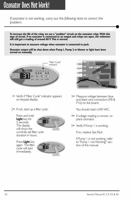
1• Verify if "Filter Cycle" indicator appearson keypad display.
2• If not, start up a filter cycle:
Press and holdLight key for5 seconds. The displaywill show thecurrently set filter cycleduration in hours.
Press Light keyagain. The filtercycle will startimmediately.
3• Measure voltage between blueand black wire connectors (P8 &P16) on the board.
You should read ≈240 VAC.
4• If voltage reading is correct, re-place ozonator.
5• Verify if Pump 1 is working.
If so, replace Spa Pack.
If Pump 1 is not working, referto "Pump 1 not Working!" sec-tion of this manual.
"Filter Cycle"indicator
Ozonator Does Not Work!
If ozonator is not working, carry out the following tests to correct the problem:
To increase the life of the relay, we use a "snubber" circuit on the ozonator relay. With this type of circuit, if no ozonator is connected to an output and relays are open, the voltmeter will still get a reading of around 60 V. This is normal.
It is important to measure voltage when ozonator is connected to pack.
Ozonator output will be shut down when Pump 1, Pump 2 or blower or light have been turned on manually.
52 Service Manual SC-CF CE & AS 53Service Manual SC-CF CE & AS

Replacekeypad.
Replace keypadby a spare one.
ReplaceSpa Pack.
Are keys working?
yes no
Keys Flow ChartIf any of the keys on the keypad do not seem to be working, follow Troubleshooting Flow Chart below to identify the problem:
Verifyjumpersettings.
52 Service Manual SC-CF CE & AS 53Service Manual SC-CF CE & AS

Keys Don't Work!If any of the keys do not seem to be working, carry out the following tests to correct the problem:
3• Verify if keys respond correctly.
4• If they do, replace keypad.
5• If they do not respond, replaceSpa Pack.
2• Replace spa keypad with a sparekeypad.
1• Verify that jumper JMP3 is setproperly. An incorrect settingmay cause a key not to respond.
Jumper location
54 Service Manual SC-CF CE & AS 55Service Manual SC-CF CE & AS

1• Unplug Pump 1, Pump 2, blower and ozonatorconnectors.
2• Remove two screws from front pack cover.
3• Lift the Spa Pack cover.
Replace The Spa PackWhen replacing an SC-CF Spa Pack, it is important to make sure to turn power off before proceeding.
WARNING! Make sure to open the circuit at the GFCI in order to protect yourself against electric shock.
54 Service Manual SC-CF CE & AS 55Service Manual SC-CF CE & AS

4• Disconnect power input wires.
5• Disconnect light cables, keypadand temperature probe connec-tors.
8• With wrenches, disconnect the twoheating element nuts (remove onlythe two upper nuts). Do not touchthe large nuts!
7• Loosen the nut that fixes heater(i.e., the center nut) and releaseheater ground cable.
Light
Keypad
Probe
6• Disconnect then remove the twowires at the top of the pressureswitch, then unscrew and removethe switch.
Replace The Spa PackMake sure spa valves are closed in order to avoid water leakage!
56 Service Manual SC-CF CE & AS 57Service Manual SC-CF CE & AS
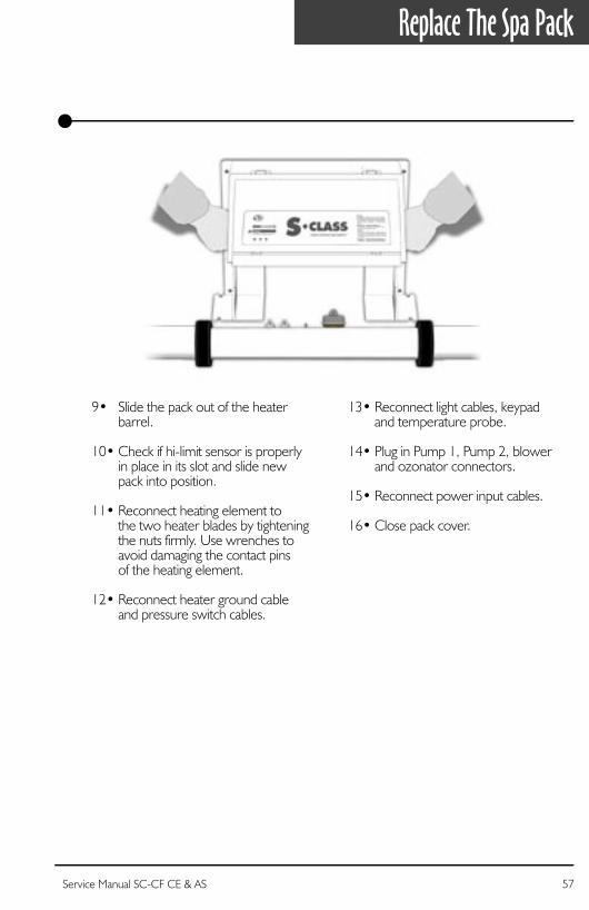
9• Slide the pack out of the heaterbarrel.
10• Check if hi-limit sensor is properlyin place in its slot and slide newpack into position.
11• Reconnect heating element tothe two heater blades by tighteningthe nuts firmly. Use wrenches toavoid damaging the contact pinsof the heating element.
12• Reconnect heater ground cableand pressure switch cables.
13• Reconnect light cables, keypadand temperature probe.
14• Plug in Pump 1, Pump 2, blowerand ozonator connectors.
15• Reconnect power input cables.
16• Close pack cover.
Replace The Spa Pack
56 Service Manual SC-CF CE & AS 57Service Manual SC-CF CE & AS

How To Adjust The Pressure Switch
1• Set voltmeter to "Ω" (while both probes are touching one another,voltmeter should beep to show there is continuity).
2• Turn Pump 1 off.
3• Do you have continuity on pressureswitch?
If you have no continuity, go to step 4.
If you do have continuity, increase pressure switch setting by turningclockwise until voltmeter stops beeping. Then decrease anotherfull turn.
4• Turn Pump 1 on at low speed andwait a few minutes.
If (3) flashing dots do not appear,you have adjusted the pressureswitch successfully.
If (3) flashing dots appear, decreasepressure switch setting by turningcounter clockwise until voltmeterstarts beeping (there is continuity).Then decrease another 1/4 ofturn. Turn pump off.
The (3) flashing dots should notappear (restart procedure if (3)flashing dots appear).
5• When adjustment procedure is completed, apply Loctite 425 tothe adjustment screw to secureit in place.
When a voltmeter is available:
58 Service Manual SC-CF CE & AS 59Service Manual SC-CF CE & AS

How To Adjust The Pressure Switch
When a voltmeter is not available:
1• Turn Pump 1 off.
2• Decrease the pressure switch settingto 0.5 P.S.I. or until three flashing dotsare displayed.
3• Start increasing pressure switch settingby very slowly turning adjustment screwclockwise until three flashing dots disap-pear. Then increase another full turn.
4• Turn pump on at low speed for 30seconds; there should be no flashingdots on display.
5• Turn pump off and wait 30 seconds. You should not see the three flashingdots.
6• If you see an error, restart the adjust-ment procedure.
If you are not able to adjust the pres-sure switch, change it.
58 Service Manual SC-CF CE & AS 59Service Manual SC-CF CE & AS

Parts ListWe recommend that field service technicians keep the items marked with an asterisk (*) in stock.
Ref.: Part Number Description Suggested Retail U.S. CDN
1 530AB0061 Tail-piece for 2" heater 5.39 7.331 530AB0042-P5 Gasket for 2" tail-piece (package of 5) 8.00 10.882 282CA0071 Nut for 2" heater 4.90 6.67 *4 9920-400178 Light cord (option LS) 7.57 10.30 *6 9920-400248 J&J mini-connector for pump 1 (CE) 7.26 9.886 9920-400282 J&J mini-connector for pump 2, single-speed (CE) 6.68 9.096 9920-400333 J&J mini-connector for pump 2, dual-speed (CE) 7.26 9.886 9920-400247 J&J mini-connector for ozonator (CE) 5.92 8.066 9920-400248 J&J mini-connector for blower (CE) 5.92 8.066 9920-400246 J&J mini-connector for circulation pump (CE) 5.92 8.0612 530AA0171 In-line 2.0 kW heater 143.17 194.7912 530AB0893 2.0 kW 240 V element for in-line heater 88.20 119.99 *13 510AD0064 Pressure switch 28.41 38.67 *19 282AD0038-P25 Ground screws (package of 25) 9.86 13.4222 430AC0103-P10 Fuses for light (package of 10) 11.14 15.15 *23 430AE0033-P10 Fuses for pump 1 (package of 10) 56.57 76.97 *29 282AB0128 Screws for cover (package of 25) 7.68 10.4530 9920-400342 10-foot temperature probe with grommet (CE) 22.20 30.16
Prices subject to change without prior notice.
60 Service Manual SC-CF CE & AS 61Service Manual SC-CF CE & AS

Wiring DiagramThe diagram below provides a general idea of SC-CF wiring, but it is important to note that it may not apply to all systems. The diagram including on inside power box cover is the one to be used as main reference for the spa you are servicing.
KEYP
AD W
/ DIS
PLAY
TEM
PERA
TURE
PRO
BE
240
VAC
INPU
T
Pump 1Voltage 230 VGreen / Ground P4Black / Low Speed P14Brown / High Speed P12Blue / Neutral P7
Pump 2Voltage 230 VGreen / Ground P5Black / Line P11Blue / Neutral P9
Jumper SettingsSee respective section
HeaterLine P21Neutral P17Green / Ground Ground
OzonatorVoltage 230 VGreen / Ground P5Black / Line P16Blue / Neutral P8
Light ConnectorWhite / 0 VAC P23Black / 12 VAC P22
HEATER OUTPUT PRESSURE SWITCH
LIGH
T
60 Service Manual SC-CF CE & AS 61Service Manual SC-CF CE & AS

• Top side controls (keypads)• Temperature probes• Pressure switch cables• Flow switches• Elements• Heater wires• Transformer• Ground lugs• Grommets• Standoffs• Light cords• Strain reliefs for light cord• Plugs• Fuse kits• Screws
Gecko's professional repair kit containsall you need to service and repairGecko's line of spa packs.
Call 1.800.78.GECKOto order or for more info!
Professional Repair KitAll you need in one case!

COMPLETE SERVICEGUIDE WITHSTEP-BY-STEP
INSTRUCTIONS ON:
GFCI Troubleshooting•
Jumper Selection•
Understanding& Correcting
Error Conditions•
System Malfunctions•
Part ReplacementInstructions
•& More
Heater connectors
J&J or AMP connectors
Easy access to probes & switches
120 V or 240 V power input
Mounting feet for installation
• E Q U I P P E D W I T H G E C K O ' S E X C L U S I V E •
SmartWinterMode TM 1.866.NEW.SBSG (1.866.639.7274)
www.sbsg-equipment.com9919-100497-BREV. 07/05