service manual - amazon s3 velasca 01 introduction 2/6 when the machine arrives at the service...
TRANSCRIPT

Coffee Machine
Service
Service Manual
Rev 00 MARCH 2017
All parts of this document are the property of Saeco International GroupAll rights reserved This document and all the information herein is provided without liability deriving from any errors or omissions Furthermore no part may be reproduced used or collected except where express authorisation has been provided in writing or through a contractual agreement
Published by Saeco International Group Subject to modification
GAGGIA VELASCA CMF-OTC
01032017
General Information
Description Value
Housing material Thermoplastic material
Size (w x h x d) 256mm x 340mm x 440 mm (data may vary depending on the model)
Weight 90 kg (data may vary depending on the model)
Power Cord length 12m
Control panel Front panel
Water tank 15 litres
Coffee bean hopper capacity 300 g
Coffee grounds drawer capacity 10
Pump pressure 15 bar
Boiler Stainless steel type
Safety devices Thermal fuse
GAGGIA VELASCA
4 Operating logic41 Water circuit 142 Coffee cycle 243 Single microswitch 3431 Temperature sensor (adjustment) 344 Coffee grinder 230V 445 Autodose system description 230V 446 Coffee lack detection and coffee grinder blocked 230V 547 Water level detection (water tank) 6
5 Service Mode51 Test Mode 152 Steam Out 753 Error Codes for Out of Order alarm 854 Saeco Service Center - Quick Start Guide 8
6 Service and maintenance61 Repair flow 1
48 Milk Carafe 649 AquaClean water filter 7
Table of contents Page1 Introduction
11 Documentation required 112 Tools and resources 113 Material 114 Safety warnings 115 Service POLICY grid as used for coffee machines 3161 External machine parts (CMF) 4162 External machine parts (OTC) 5163 Internal machine parts 6
2 Technical specifications
21 Technical specifications 122 Machine parameters and performance 123 Specification for the measurement of the coffee products
temperature3
231 Specification for the measurement of the Milk products temperature
4
3 Brief instructions
31 Customer menu GAGIA VELASCA CMF 132 Customer menu GAGGIA VELASCA OTC 133 Warning icons 234 Troubleshooting 2
Table of contents Page
7 Disassembly
71 Outer Shell 172 Coffee grinder 173 Grinder blades 274 Coffee grinder adjustment 275 Carafe connection and hotsteam water dispenser 376 Removing tap 377 Pump 378 Flow-meter 379 Boiler 4710 CPU board 4711 KYB interface and display 4712 Gear motor 5713 Fitting and removing Oetiker clamps 6
8 Notes
9 Water circuit diagram91 Water circuit diagram 1
10 Electrical diagram101 Electrical diagram 1
MODIFICATIONS TO SERVICE MANUALFrom Rev To Rev Chapter Inserted Modified
GAGGIA VELASCA
CHAPTER 1 INTRODUCTION
GAGGIA VELASCA 01 INTRODUCTION
16
11 Documentation required
The following documentation is needed for repair proceduresbull Instruction booklet for specific modelbull Technical documentation for specific model (diagrams exploded view sympton cure and service
manual)
12 Tools and resources
As well as the standard equipment the following is required
13 Material
14 Safety warnings
We recommend you consult the technical manual of the machine before performing any mainte-nance workObserve all applicable standards relating to the repair of electrical appliancesAlways disconnect the power plug from the mains before beginning repair workAlways disconnect the power plug from the mains before beginning repair work
Simply turning off the main machine power switch is not an adequate safety precautionThis domestic appliance is rated as insulation class IOn completion of the repair work insulation and dielectric rigidity tests must be per-formedDisassembling the machine the operator must pay attention to hot and under pressure parts boiler pin-boiler valves dispensing steam tube brew unit connections and pipes to avoid burnsPlease refer to specific hydraulic circuit (Image1) to know the parts in detail The machine hydraulic circuit can reach maximum pressure of 1618 barTo operate in safety condition is recommended to perform the Steam Out procedure in order to remove the pressure and hot water inside the hydraulic circuit
12NC Material Code and Description- Thermal paste Heat resistance gt 200degC996530067222 Descaler ldquoACC SAE DECALCIFIER 5 L 1 UNITrdquo132253695601 Grease solvent ldquoPARALIQ GB 363rdquo996530045784 Silicone grease ldquoACC TUBE FIN FOOD GREASE 2 400 MLrdquo
12NC Description Notes- Screwdriver- Pliers for Oetiker clamps - CC -A - Vdc tester- Digital thermometer Scale limit gt 150degC
996530009845 Serkit Tool needed for programming with SSC
- SSC (Saeco Service Center)Tool used to flash the SW on the machines (for SW upgrade and diagnostics mode) Refer to SDA_111359
GAGGIA VELASCA 01 INTRODUCTION
26
When the machine arrives at the Service Center in descaling mode interrupted or making Descal-ing be very careful not to come into contact with the DescalerAfter the product has been repaired it should function properly and has to meet the safety require-ments and legal regulations as officially laid down at this moment
Pump
Safety valve
Water discharge
Steam pipeWater tank
Two-way solenoid valve
Brewing Unit
Flowmeter
Boiler
Water Hot water steam
From this point circuit High temperaure
From this point circuit in pressure
Flowmeter
Steam and hot water
Two-way solenoid valve
PumpBrewing Unit
Boiler
Safety valveWater
discharge
Water tank
Image 1
GAGGIA VELASCA 01 INTRODUCTION
36
Components Assembly use Single components availableCOFFEE
GRINDER Only for OOW repairs YES to consult the specific exploded-view of the machine or of the Coffee Grinder on website
BREWING UNIT Only for OOW repairs YES to consult the specific exploded-view of the
machine or of the Brewing unit on website
BOILER Only for OOW repairs YES to consult the specific exploded-view of the machine on website
GEAR MOTOR Only for OOW repairs YES to consult the specific exploded-view of the
machine on websiteFILTER
HOLDER Only for OOW repairs YES to consult the specific exploded-view of the machine on website
MILK CARAFE Only for OOW repairs YES to consult the specific exploded-view of the
machine on websiteTHERMAL CARAFE Only for OOW repairs YES to consult the specific exploded-view of the
Thermal Carafe on website
MILK ISLAND Only for OOW repairs YES to consult the specific exploded-view of the Milk Island on website
List of principal assembly present in all our coffee machines
15 Service POLICY grid as used for coffee machines
For IN WARRANTY repairs is raccomanded to use when and where possible the single compo-nents available in the exploded views of the coffee machines or of the specific components If you find the information ldquoSEE THE EXPLODED VIEW Erdquo in the assembly description field it means that the single components of the assembly are available in the other pages of the exploded view Itrsquos possible to use the assembly only if there is a specific Symptom Cure that include this possibili-ty or when the single components are not available for the order
421946031741 REV01
4219_460_3174_1_Leaet_A5_v1indd A5 V 140715 0833
421946031741 REV01
4219_460_3174_1_Leaet_A5_v1indd A5 V 140715 0833
421946031741 REV01
4219_460_3174_1_Leaet_A5_v1indd A5 V 140715 0833
4219_460_3173_1_Leaet_A5_v1indd 4-1
GAGGIA VELASCA 01 INTRODUCTION
46
161 External machine parts (CMF)
1 Coffee bean hopper lid2 Coffee bean hopper3 Power cord socket4 Water tank5 Pre-ground coffee compart-
ment6 Grinder adjustment knob7 Control panel8 Coffee grounds container9 Dispensing spout10 Drip tray11 Drip tray cover12 Drip tray full indicator13 Espresso button14 Espresso lungo button15 Aroma strength button16 Standby button17 Menu button18 Hot water button19 Steam button20 Power cord21 Cleaning brush (for specific
types only)22 Grease for the brew group
(for specific types only)23 Pre-ground coffee measur-
ing spoon24 Water hardness test strip25 Coffee residues drawer26 Brew group27 Steam wand28 Classic milk frother
1
12
16
26 25
20
5
10 11
6
9
7
8
2
4
13 19
14 18
15
24
23
21 22
2827
17
3
421946031721 REV01
4219_460_3172_1_Leaet_A5_v1indd A5 V 140715 0829
421946031721 REV01
4219_460_3172_1_Leaet_A5_v1indd A5 V 140715 0829
421946031721 REV01
4219_460_3172_1_Leaet_A5_v1indd A5 V 140715 0829
4219_460_3173_1_Leaet_A5_v1indd 4-1
GAGGIA VELASCA 01 INTRODUCTION
56
162 External machine parts (OTC)
1 Coffee bean hopper lid2 Coffee bean hopper3 Power cord socket4 Water tank5 Pre-ground coffee compart-
ment6 Grinder adjustment knob7 Control panel8 Coffee grounds container9 Dispensing spout10 Drip tray11 Drip tray cover12 Drip tray full indicator13 Espresso button14 Espresso lungo button15 Aroma strength button16 Carafe quick clean button17 Standby button18 Menu button19 Special drinks button20 Milk froth button21 Cappuccino button22 Power cord23 Cleaning brush (for specific
types only)24 Grease for the brew group
(for specific types only)25 Pre-ground coffee measur-
ing spoon26 Water hardness test strip27 Coffee residues drawer28 Brew group29 Milk carafe30 Hot water dispensing spout
1
12
1716 18
28 27
22
5
10 11
6
9
7
8
2
4
13 21
14 20
15
26
25
23 2430
29
19
3
GAGGIA VELASCA 01 INTRODUCTION
66
163 Internal machine parts
Turbine
Pump
Safety valve
PWCPU PCB
Coffee grinder motor
motor resistance grinder
Valve
Grinding adjustment insert
Boiler
Coffee grinder
Boiler pin
GAGGIA VELASCA
CHAPTER 2 TECHNICAL SPECIFICATIONS
GAGGIA VELASCA 02 TECHNICAL SPECIFICATION
15
21 Technical specifications
Power supply and output 240 V~ 50 Hz 1850 W - 230 V~ 5060 Hz 1850 W 120 V~ 60 Hz 1500 W
Temperature monitoring (NTC) variable resistor sensor - transmits the value to the electronic card
Safety system 2 thermostats at 190degC one shotCoffee heat exchanger output Stainless steel
(230 V~) 1900 W - (120 V~) 1300 W - (100 V~) 1100 W for coffee hot water and steam dispensing
Gear motor 2 rotation directions power supply 24VCSteam heat exchanger output Stainless steel As above
Pump Ulka Type EP5S GW approx 13-15 bar with reciprocating piston and thermal switch 100degC 48 W 230V 50 Hz 120V 60Hz 100V 5060 Hz
Overpressure valve Opens at approx 16-18 barWater filter In tank Coffee grinder Direct current motor with flat ceramic grinder blades Automatic dosage Dose adjustment controlled by the electronic system Power consumption During the heating phase - approx 56 ADimensions W x H x D in mm 256x340x440 (data may vary depending on the model) Weight 90 Kg (data may vary depending on the model)Water tank capacity 15 litres Coffee container capacity 300 g Coffee dreg drawer capacity 10Water circuit filling time Approx 15 seconds for first filling cycleHeating time Approx 30 secondsGrinding time Approx 8-10 seconds
22 Machine parameters and performance
PRODUCT QUANTITY
Minimum quantity(Puls)
Default quantity(Puls)
Maximum quantity(Puls)
User programmable
Programm by Production
ServiceEspresso 50 165 600 Yes No
Long coffee 70 440 600 Yes NoPre-ground NoHot water Continues until the water supply has been exhausted (capacitive sensor)
Steam pannarello (frother)
Continues until the water supply has been exhausted (capacitive sensor)
GAGGIA VELASCA 02 TECHNICAL SPECIFICATION
25
RINSE Initial rinse Final rinseWhen performed When the machine is switched
on and the boiler temperature is le 50degC
When the machine is switched off electronically manually or auto-matically after 30 if at least one coffee has been dispensed be-
fore switching offNo of pulses 180 80
Stopping option Yes by pressing any key Yes by pressing any keyUser disable option No No
ProductionService de-partment disable option No No
No of pulses user adjust-ment option No No
No of pulses ProductionService department ad-
justment optionNo No
Pulse range(Min ndash Max) No No
If after descaling or after the use of a filter this is not reactivated the machine recognizes the water hardness setting and calculates as in the table below (NO AQUACLEAN)
Descaling cycle frequencyHardness WATER HARDNESS Without water filter Not reactivating the filter
1 Soft (up to 7degdH) 240 litres (480000 pulses) 210 litres (420000 pulses)2 Medium (7deg - 14degdH) 120 litres (240000 pulses) 105 litres (210000 pulses)3 Hard (15deg - 21degdH) 60 litres (120000 pulses) 525 litres (105000 pulses)4 Very hard (over 21degdH) 30 litres (60000 pulses) 2625 litres (52500 pulses)
The default water hardness level is 4 Each litre of water corresponds to approximately 2000 pulses
Descaling cycle frequency with AQUACLEAN filterThe first activation must make before youve paid up to 500 l products because mind thinks as if he had the filter
Hardness Filter num-ber
Percentual on display 10 the icon flashes slowly (encourage the consumer to buy the
filter)
Percentual on display 0 the icon flashes quickly (tell the con-sumer to change the
filter)
MAX Quantity water the icon
turns off (replace filter)
Indiffe-rent
From 18 to 78 800 l 20 l 110 l
Replace filter (you can not
turn off) 88 Descaling
If after descaling or after the use of a filter this is not reactivated the machine recognizes the water hardness set-ting and calculates as in the table below
GAGGIA VELASCA 02 TECHNICAL SPECIFICATION
35
23 Specification for the measurement of the coffee products temperatureThe temperature is influenced by the flow from the dispenser and stratification of temperatures in the glass In order to consider these phenomena and to introduce measures that allow comparisons in controlled conditions below guidelines must be followedConditionsa) Water temperature in tank 23degC (+-2degC)b) It must be used a plastic cup (see picture Ndeg1)c) It must be used a thermocouple thermometer (eg type K - see picture Ndeg2)d) The coffee machine is tested without any change of parameters or calibrations which may affect the temperature of products so the measurement of temperature must be done with machine in default factory setting Procedure1 The temperature must be measured in the cup immediately after dispensing Cup has to be placed on a non-metal surface using a thermocouple thermometer (Picture 1)
2 The temperature in the cup is measured by immersing the probe of the thermometer up to touch the bottomThe probe then must be moved in a circular motion for 56 rotations At the of the rota-tions stop in the center of the cup (Picture 2)
3 The highest temperature measured during the rotations is the value we are searching for and that must be reported
4 Test measurement from end of dispensing to the end of rotations must be completed within 12 seconds
5 the distance of the probe from the bottom of the glass is a function of the quantity of coffee dis-pensed 10mm for 35gr - 17mm for 60gr - 35mm for 120gr and superior (Picture 3) Limits of acceptabilityThe acceptance limits are divided by features and products and are the following
Espresso Coffee Italy Qty 2540 grTemperature of 1st product 69degC le 85degCTemperature of 2nd product 72degC le 85degC
Coffee Qty 70120 grTemperature of 1st product 69degC le 85degCTemperature of 2nd product 72degC le 85degC
Picture 1 Picture 2
OFF Tare ON
10 mm
for 120gr and superior
Oslash max 2mm
17 mmfor 60gr
35 mm
for 35gr
Picture 3
DISPLAY
GAGGIA VELASCA 02 TECHNICAL SPECIFICATION
45
231 Specification for the measurement of the Milk products temperature
Milk evaluationTo carry out the test a partially skimmed UHT milk with a percentage of grease between 15-18 at a refrigerator temperature Trefr (between 4 to 10degC) must be usedThe milk product must be checked on a beaker of 250 ml of capability and with an inner diameter of 70mm brewing 100gr of product
Parameters to be respectedThe parameters to be respected are milk temperature and height of the cream Each of these pa-rameters however must be evaluated depending on the type of system used for the production of hot milk Actually three types of devices are present on the appliancesbull Manual system (pannarello)bull Semi-Automatic system (cappuccinatore)bull Automatic system (carafe Pinless wonder system etc)
Milk temperature in the beakerSystem with Pinless Wonder With milk at Trefr (about 4-10 degC) ge 45how does it work 1 The milk is heated in the first chamber of the carafe thanks to the steam 2 Then it is mixed with air and frothed in the middle chamber 3 Finally in the outlet chamber the lsquotyphoon effectrsquo perfects the milk texture by removing the large bubbles
Height of the milk cream in the beakerManual system (pannarello) ge 15mm on 100gr of brewed productSemi-automatic system (cappuccinatore) ge 20mm on 100gr of brewed productAutomatic system carafe cappuccinatore Pinless wonder eg (New Royal Energica Pure Intelia EVO latte) ge 20mm on 100gr of brewed product
How to measure the temperature of the milk
1 The measurement is carried out in the beaker immediately after the end of milk brew positioned on a non-metallic surface using a thermocouple thermometer (eg Type K) Stop the preparation of mixed product at the end of milk brewing where ldquoOne Touch productrdquo function is present
2 The temperature is measured by immersing the probe of the thermometer positioning the probe inside the beaker at about 10mm from the bottom of the container then the probe moves in a circular motion for 3-5 turns stopping at the end at the center of the beaker It detects the max-imum temperature reached in a time of relief between 3 to 5 seconds It is important the mixing of milk before the measurement at 10mm from the bottom of the beaker If the mixing is correct temperature for a few fractions of a second during the measurement should not oscillate
Emulsified milk
Emulsion chamber
Steam
Milk
GAGGIA VELASCA 02 TECHNICAL SPECIFICATION
55
How to measure the milk creamThe temperature (Trefr or Tamb) of the milk doesnrsquot affect as much the test result on measuring the milk cream by convection is assumed to always use milk at refrigerator temperature Trefr
Manual systems (Pannarello)Pour 100cc of milk at Trefr in a beaker of 250 ml of capacity and with a inner diameter of 70 mm with machine in steam mode
1 Open the steam knob to discharger water circuit for 4 sec then close the knob 2 Place the beaker with the frother dipped in milk open the steam knob to maximum and start
the chronometer3 After about 30 to 60 seconds close the knob and check the result on milk
Semi-automatic systems (cappuccino)Pours milk at Trefr in a container with the machine in steam mode
1 Open the steam knob to discharge water circuit for 4 sec then close the knob 2 Insert the silicone tube in the milk container placing a beaker of 250 ml capacity and with an
inner diameter of 70 mm under the cappuccino maker and open the steam knob 3 After having provided 100gr of product close the knob and check the result obtained on milk
Note The same applies to machines which have a steam key on the user interface and a sole-noid valve in place of the steam tap
Automatic Carafe Cappuccino Pinless wonder eg(New Royal Energica Pure Intelia EVO Latte) etcAfter setting the machine to delivery of 100gr of product
1 Launch the ldquohot milkrdquo function 2 Collect the product in a beaker with a 250ml of capacity and with an inner diameter of 70 mm
and verify the result obtained on milk Carry out the test using milk at a Trefr
In case the machine allows modify of the emulsion through the menu use the machine with the emulsion set to the default value
Related to the above testing procedure derives the following table of acceptability
Manual Semi-Automatic and Automaticrsquos Milk SystemGrams of Product Minimun Height of the milk cream
ge 130 ge 30mm120 ge 25mm110 ge 22mm100 ge 20mm90 ge 16mm80 ge 13mm70 ge 11mm
NB To verify more accurately the height of the cream a practical expedient dictated by experience is to add to the product just delivered a small amount of coffee The addition of coffee immediately put in evidence the surface of separation between liquid and cream
GAGGIA VELASCA
CHAPTER 3 BRIEF INSTRUCTIONS
GAGGIA VELASCA 03 BRIEF INSTRUCTIONS
16
31 Customer menu Gaggia Velasca CMF
32 Customer menu Gaggia Velasca OTC
Control Panel
Control Panel
Espresso brew button and ESC button
Espresso brew button and ESC button
Long espresso brew button
Long espresso brew button
AROMA STRENGTH but-ton and OK button
AROMA STRENGTH but-ton and OK button
Steam button and UP button
CAPPUCCINO button and UP button
MENU button and DOWN button
SPECIAL DRINKS button and DOWN button
ONOFF button
ONOFF buttonCARAFE QUICK CLEAN button
MENU button
Hot water button
MILK FROTHER button
GAGGIA VELASCA 03 BRIEF INSTRUCTIONS
26
33 Warning icons
34 Troubleshooting
Fill the water tank with fresh water to the MAX level indication
The brew group is not in the machine Insert the group
Remove the coffee grounds container and empty it
- There is too much powder in the brew group Clean the brew group- If an error code is triggered check the section lsquoMeaning of error codesrsquo to see what the code on the display means and what you can do The machine cannot be used when this icon is on the display
You forgot to place the lid on the pre-ground coffee compartment If you do not place it back within 30 seconds the display will return to the main menu and the brewing cycle will be stopped
The bean hopper is empty Put new coffee beans in the bean hopper
Close the service door
Warning signals are displayed in red Below you find a list of the warnings that may appear on the display and their meaning
18 The display shows the following icon to indicate that the machine isheating up
- The machine performs an automatic rinsing cycle19 Remove the container Remove and empty the drip tray SLide the drip
tray back into the machine20 Place the AquaClean lter back in the water tank Reinsert the automatic
milk frother21 Remove and rinse the brew group see chapter lsquoCleaning and
maintenancersquo section lsquoClean the brew grouprsquo
The machine is now ready for use
Interruption of the descaling cycle Once the descaling cycle has started you must complete it till the very endwithout turning o the machine In case you get stuck during the cycle or incase of power failure or accidental disconnection of the power cord youcan exit by pressing the standby button If this occurs empty and rinsecarefully the water tank then ll it up to the CALC CLEAN level Follow theinstructions in chapter lsquoFirst installationrsquo section lsquoManual rinsing cyclersquobefore brewing any beverage If the cycle was not completed the machinewill require another descaling cycle to be performed at your earliestconvenience
Warning icons and error codes Warning signals are displayed in red Below you nd a list of thewarnings that may appear on the display and their meaning- Fill the water tank with fresh water to the MAX level indication
- The bean hopper is empty Put new coee beans in the bean hopper
20 English
- The brew group is not in the machine Insert the group
- Close the service door
- Remove the coee grounds container and empty it
- There is too much powder in the brew group Clean the brew group- If an error code is triggered check the section Meaning of error codes to
see what the code on the display means and what you can do Themachine cannot be used when this icon is on the display
- You forgot to place the lid on the pre-ground coee compartment If youdo not place it back within 30 seconds the display will return to the mainmenu and the brewing cycle will be stopped
Meaning of error codesError code Problem Cause Possible solution
21English
Problem Cause Solution
The machine does not switch on
The machine is disconnected orthe main switch is in the OFFposition
Check if the mains cord is insertedcorrectly
Make sure the main switch is set in ON position (AMF-CMF)
The machine is in DEMO mode
The standby button has been pressed for more than 8 seconds
Switch the machine off and then onagain using the main switch on theback of the machine
The drip tray is quickly filled
This is normal The machine useswater to rinse the internal circuit and brew group Some water flows through the internal systemdirectly into the drip tray
Empty the drip tray when the lsquodrip tray fullrsquo full indicator pops up through the drip tray cover
Place a cup under the dispensing spout to collect rinsing water
GAGGIA VELASCA 03 BRIEF INSTRUCTIONS
36
The coffee groundscontainer full icon remains displayed
The coffee grounds container was emptied while the machine was switched off
Always empty the coffee grounds container while the machine is ON Ifthe coffee grounds container is emp-tied while the machine is switched off the coffee cycle counter is not re-set In that case the lsquoempty coffee grounds containerrsquo message will stay on the display even though the con-tainer is not full
The coffee grounds container was placed back too fast
Do not place back the coffee groundscontainer until the screen message prompts you to put it back
The brew group cannot be removed
The brew group is not positioned correctly
Close the maintenance door Switch the machine off and back on again Wait for the machine ready screen toappear and then remove the brew group
The coffee grounds container is not removed
Remove the coffee grounds containerbefore removing the brew group
The machine is still in the descal-ing process
You cannot remove the brew group when the descaling process is active First complete the descaling process and then remove the brew group
The brew group cannot be inserted
The brew group is not in the cor-rect position
The brew group was not put in rest position before it was placed back Make sure that the lever is in contact with the base of the brew group and that the hook of the brew group is in the correct positionReset the machine by switching it on and off Place the drip tray and the coffee grounds container back Leave the brew group out Close the main-tenance door and switch the machine on and off Then try to reinsert the brew group
The coffee has too little cream or is watery
The grinder is set to a coarse setting Adjust the grinder to a finer setting
The brew group is dirtyClean the brew group For thorough cleaning follow the monthly cleaning procedure with the degreasing tablet
The coffee exit duct is dirtyClean the coffee exit duct thoroughly with the handle of the multifunctional tool or a spoon handle
GAGGIA VELASCA 03 BRIEF INSTRUCTIONS
46
The coffee blend is not the correct one Try another coffee blend
The machine is performing its self-adjustment Brew a few cups of coffee
The coffee is not hot enough
The cups you use are cold Preheat the cups by rinsing them withhot water
The temperature is set too low Check the menu settings
Set the temperature to high in the menu
You added milkWhether the milk you add is warm or cold it will always decrease the tem-perature of the coffee to some extent
The machine grinds the coffee beans but coffee does not come out
The grind is set too fine Adjust the grinder to a coarser set-ting
The brew group is dirty Clean the brew group
The coffee dispensing spout is dirty
Clean the coffee dispensing spout andits holes with a pipe cleaner
The coffee exit duct is blockedClean the coffee exit duct with the handle of the multifunctional tool or aspoon handle
The coffee comes out slowly
The grind is ground too finely Change the grinder to a coarser set-ting
The brew group is dirty Clean the brew group
The coffee exit duct is blockedClean the coffee exit duct with the handle of the multifunctional tool or aspoon handle
The machine circuit is blocked by limescale Descale the machine
The milk does not froth
The automatic milk frother is dirty or not assembled or installed cor-rectly
Clean the automatic milk frother and make sure it is correctly assembled orinstalled (AMF-CMF)
The type of milk used is not suita-ble for frothing
Different types of milk result in dif-ferent amounts of froth and different froth qualities Semi-skimmed or full-fat cowrsquos milk give good results
The milk carafe is dirty or not inserted correctly
Clean the carafe and make sure that you position and insert it correctly (OTC)
The milk froth dispensing spout asnot been opened fully
Check that the milk froth dispensing spout has been set in the correct po-sition (OTC)
GAGGIA VELASCA 03 BRIEF INSTRUCTIONS
56
The milk carafe is incompletelyassembled
Check that all the componentshave been assembled correctly (OTC)
The AquaClean fil-ter cannot be ac-tivated as the tick does not appear on the display
A filter has just been activated
You have to dispense at least 10 cups(of 100ml each) before you can ac-tivate a new filter Be careful as you activate a new filter the filter counterwill increase automatically
The filter cannot beactivated and the machine asks for descaling
You have already replaced 8 AquaClean filters After 8 filter replacements you need to descale the machine
Descale your machine first and installthe filter
The filter has not been replaced in time after the AquaClean water filter signal started flashing
Descale your machine first and installthe filter
The filter has not been installed during first installation but after having brewed approx50 coffees (based on 100ml cups) The machine has to be completely limescale-free before installing the AquaClean filter
First descale the machine and then install a new AquaClean filter After descaling the filter counter is reset to 08 Always confirm filter activation inthe machine menu also after filter re-placement
The AquaClean filter was notcorrectly activated during firstinstallation
Follow the instructions on the displayuntil you receive confirmation that thefilter has been activated
The AquaClean fil-ter is installed but the descaling mes-sage appears
After 8 filter replacements you need to descale the machine
First descale the machine and then install a new AquaClean filter This willreset the filter counter to 08 Alwaysconfirm filter activation in the machinemenu also after filter replacement
The descaling mes-sage appears be-fore 8 filters were replaced
You did not activate the Aqua-Clean filter correctly during first installation
First descale the machine and then install a new AquaClean filter Alwaysactivate the filter in the machine menu
You placed the AquaClean filter after having used the machine for a whileYou did not activate the replace-ment filter in the machine menuYou did not replace the filter when the filter symbol started flashing
The filter does not fit
You need to remove air from thefilter Let air bubbles come out of the filter
There is still water in the watertank
Empty the water tank before youinstall the filter
GAGGIA VELASCA 03 BRIEF INSTRUCTIONS
66
You try to install another filter than the AquaClean filter Only the AquaClean filter will fit
There is water un-der the machine
The drip tray is too full and over-flowed
Empty the drip tray when the drip trayfull indicator pops up through the driptray Always empty the drip tray be-fore you start descaling the machine
The machine is not placed on ahorizontal surface
Place the machine on a horizontal surface so that the drop iray full indi-cator works properly
GAGGIA VELASCA
CHAPTER 4 OPERATING LOGIC
Pump
Flow
meter
GAGGIA VELASCA 04 OPERATING LOGIC
17
Wat
er ta
nk
Boile
r
Pum
p
Flow
met
er
Wat
er
disc
harg
eSa
fety
val
ve
Brew
ing
Unit
Stea
m a
nd h
ot w
ater
or m
ilk c
araf
e
Two-
way
sol
enoi
d va
lveW
ater
Ho
t wat
er s
team
41 Water circuit
GAGGIA VELASCA 04 OPERATING LOGIC
27
42 Coffee cycle
Notes Only with Pre-brewing
Switching onWhen the machine is switched on the gear motor repositions itself as follows- It acts on microswitch 1 (see following chapter)- The gear motor changes its rotation direction and moves upwards again by approx 1-2 mm- The boiler begins to heat the water for approx 45 sec at full power in order to reach the
optimal temperature The temperature will then remain at a constant level
Coffee cycle1 The coffee grinder starts the grinding process (controlled by pulses generated by a sensor)2 The gear motor (brewing unit) moves to the brewing position3 Preliminary dispensing phase (short pump activity short pause)4 Product dispensing (the pump operation period is defined by the amount of product dis-
pensed)5 The gear motor moves to its home position (the dregs are expelled automatically)
Main switch ON START STOPTime
Coffee grinder
Heating
Pump
Brewing unit gear motor
Status Heating Ready Coffee cycle
Pulses (Dosage)
Pump operation (flow meter pulses) in
accordance with the amount of product
selected
approx 45 sec
Single microswitch gear motor
StatusMicroswitch OFF ON
GAGGIA VELASCA 04 OPERATING LOGIC
37
43 Single microswitch
Switching onWhen the machine is switched on the gear motor repositions itself as follows- It acts on microswitch 1 - The gear motor changes its rotation direction and moves upwards again by approx 1-2 mm- The boiler begins to heat the water for approx 45 sec at full power in order to reach the optimal
temperature The temperature will then remain at a constant level
An NTC is used as a temperature sensor in the event of overheating this reduces boiler element power consumptionThe electronic system detects the current boiler temperature from the drop in voltage of the sensor and adjusts it accordinglyHeating element values and corresponding temperatures see table
431 Temperature sensor (adjustment)
Temp (degC) R nom (kΩ) ΔR (+- )20 61465 8650 17599 5975 7214 4180 6121 3785 5213 3490 4459 31
100 33 25125 1653 39150 0893 51
The gear motor is powered by a direct current mo-tor that engages with the smaller double toothed wheel using a worm screw The unit is mounted on the axle of the large gear wheel and when a coffee is requested it moves from the standby position to the dispensing position and then back to the standby position again
- Standby position 1
- Dispensing position 2
2
1
GAGGIA VELASCA 04 OPERATING LOGIC
47
45 Autodose system description 230VmA
I0
I0 + 100
I0 + 55
I0 + 200Aroma 45
Aroma 23
Aroma 1
Auto-Zero
100le I0 le300
I0 = current when the BU is moving without load ie without coffee It occurs for example dur-ing the rinsing phase of coffee spout Current targets
Aroma 1 55mAAroma 23 100mAAroma 45 200mA100 mA le I0 le 300 mA
If the BU current is le the current target the grinding timeIf the BU current is ge the current target the grinding time
44 Coffee grinder 230V
The coffee grinder is driven by a direct current motor (1) using a worm screw helicoidal wheel transmission (2)The worm screw (2) drives a plastic gear wheel (3) which turns the lower grinder (4) and the increment pin (5)
23
4
5
1
GAGGIA VELASCA 04 OPERATING LOGIC
57
1) When the system get the stability (ie the system got the current target) the coffee doses should be A1 A23 A45
75 90 10 plusmn15 grams
with medium grinding (500plusmn60μm) and using coffee of test
2) the 3 grinding times are always
T1ltT2ltT3
beside every grinding time is respectively
40s leT3 le10s (10000ms)35s leT2 le9s (9000ms)30s leT1 le81s (8100ms)
DOSE ADJUSTMENT
5 levels Grinder Time
Min Grinder
Time
Max Grinder
TimeCurret target
Aroma of the
grinded product
Aroma1 Very Light T1 3s 81s I0 + 55mAAroma2 Light T2 35s 9s I0 + 100mAAroma3 Med
Aroma4 Strong T3 4s 10s I0 + 200mAAroma5 Very Strong
46 Coffee lack detection and coffee grinder blocked 230V
When the coffee grinder is working the software monitors the current consumption If the current value is very low the machine concludes that coffee is missing if the current value is very high the machine concludes that the coffee grinder is blocked instead if the current value is in the middle the machine concludes that all is ok and it goes on to do the productBecause the current consumption of grinder changes depending on the situations (motor new or old cold or hot etc coffee blends) these current thresholds are not static but dynamic
GAGGIA VELASCA 04 OPERATING LOGIC
67
47 Water level detection (water tank)
ldquoWater lowrdquo message (water reserve)
FunctionThe water level is monitored by a capacitative sensor located one third of the way up the water tank wallIf the electronics assembly detects by means of the sensor that the amount of water in the tank has dropped below the above mentioned level a water reserve remains available for the dispensing process underway (this will cover 200 flow meter pulses)The product dispensing process will then come to an endIf a dispensing cycle ends after the sensor has been triggered (in the reserve) then the display ldquoWater lowrdquo continues to be displayed during the following dispensing cycle
200 puls
Sensor
Water tank
48 Milk Carafe
1) Steam input2)Bring the cappuccino maker into dispensing
position 3) Milk tank
The steam passes through the pipe creating a sucking effect that pulls the milk upwards
Steam
The milk is heated by the steam and taken towards the emulsion chamber where it is mixed with air and transformed into foam
MINUTO 04 OPERATING LOGIC
Page 10
44 Milk Carafe
1) Steam input2)Bring the cappuccino maker into dispensing
position 3) Milk tank
1
2
3
04
The steam passes through the pipe creating a sucking effect that pulls the milk upwards
Steam
The milk is heated by the steam and taken towards the emulsion chamber where it is mixed with air and transformed into foam
GAGGIA VELASCA 04 OPERATING LOGIC
77
49 AquaClean water filter
The AquaClean filter is designed to reduce limescale deposits in the coffee machine and provide filtered water to preserve the aroma and flavor of each cup of coffee By using a series of 8 AquaClean filters there is no need to descale the machine for 5000 cups (It depends both on the type of coffee used rinsing and cleaning programs) We recommend installing the water filter AquaClean the first use of the machine to the maximum before using 5 L of water The machine display will indicate when the filter needs to be replaced The maximum limit is equivalent to 110 L of water The conditions related to the filter work environment (water therefore an active environment for bacteria and microorganisms) require the replacement with a minimum frequency (we suggest 3 months from the activation to ensure the best performance) The filter startsrsquo working from the time is filled with water and continues working even with the machine off It cannot be deactivated manually as it must end its life cycle At the filter activation the display shows the icon with the percentage of use
- Initially 100 then decreasingWhen the autonomy of the current filter becomes less than 8 L of water the display shows
- The icon flashing slowly It means 10 When the autonomy of the current filter becomes less than 2 L of water the display shows
- The icon flashing quickly It means 0 After a maximum of 110 L of water supplied the flashing light turn off and the machine needs to be descaled
GAGGIA VELASCA
CHAPTER 5 SERVICE MODE
GAGGIA VELASCA 05 SERVICE MODE
18
51 Test Mode
IntroductionThis document describes the manual Test Mode of the GAGGIA VELASCA coffee appliance
To enter Test Mode To activate the manual Test Mode the user must press at the same time the ldquoEspressordquo and ldquoMenurdquo (ldquoSpecial Drinksrdquo for OTC version) buttons while connecting the CA to the power supplyOnce entered the Test Mode the first page of seven is shownEntering page the display shows a) The name of the machine and the installed firmware version b) The supply voltage c) The AC supply net frequency detected by the CAPage 1 Keyboard and display colors testing 1) Espresso button 2) Coffee button 3) Steam button (Aroma button for OTC version) 4) Hot Water button (Cappuccino button for OTC version) 5) Aroma button (Milk Froth button for OTC version) 6) Menu button (Special Drinks button for OTC version) 7) Stand-by button 8) Clean button (only OTC version) 9) Menu button (only OTC version)Page 2 Input signals testing a) Water tank sensor b) Door closedopened microswitch c) Coffee Brewing Unit insertion microswitch d) Dreg Drawer insertion microswitchPage 3 Coffee Brewing Unit testing a) UpDown BU movement (24V DC) b) BU effort currentPage 4 Hydraulic circuit loads testing (Pump Electrovalve) a) pump (120-230V AC) b) 2 ways Electrovalve (24Vdc)Page 5 Heater and Grinder testing a) Heater (120-230V AC) b) Grinder (320V DC)Page 6 Autodose quantities a) Light b) Med c) Strong
Test Mode INTELIA EVO V2 AMF
Filename Intelia_EVO2_AMF_TestMode_V05
50 G Divella 12062015 312 revNum Author Verified Approved SaveDate PPP
When accessing the Test Mode all the loads are turned off
11 Entering Page
Used to verify firmware version and some built-in parameters
This page shows the firmware version installed the supply voltage (230V or 120V) and the AC net frequency (50Hz or 60 Hz)
Itrsquos always required to check if the firmware version shown on the display is the same printed on the microcontroller label
Warning If the two version do not match the PCB must be dismissed
Press STEAMThe CA goes to page 1 (KEYB)
Test Mode INTELIA EVO V2 AMF
Filename Intelia_EVO2_AMF_TestMode_V05
50 G Divella 12062015 412 revNum Author Verified Approved SaveDate PPP
12 Page 1 (KEYB) Initial condition no button pressed
Press all the buttons from Ndeg1 till Ndeg9Whenever a button is pressed the ldquoONrdquo word appears near the related button number Pressing button Ndeg1 the backlight color switches from WHITE to REDPressing button Ndeg2 the backlight color switches from WHITE to PINK Pressing button Ndeg7 turns the STANDBY LED on To test button Ndeg4 it must be pressed just one time because it causes the CA to navigate to the next page
In case two or more buttons are pressed at the same time the display shows the expression ldquoTWO BTNrdquo This could be a useful warning if the keyboard is not working properly
ERRORS occur if ldquoONrdquo word does not appear or stays fixed on screen In this case itrsquos necessary to check the communication flat cable connected between the keyboard and the CPU-Power board Should not on the other hand change the display color check the JP5 cable
Pressing STEAM button The CA switches to page 2 (INPUTS)
Test Mode INTELIA EVO V2 AMF
Filename Intelia_EVO2_AMF_TestMode_V05
50 G Divella 12062015 312 revNum Author Verified Approved SaveDate PPP
When accessing the Test Mode all the loads are turned off
11 Entering Page
Used to verify firmware version and some built-in parameters
This page shows the firmware version installed the supply voltage (230V or 120V) and the AC net frequency (50Hz or 60 Hz)
Itrsquos always required to check if the firmware version shown on the display is the same printed on the microcontroller label
Warning If the two version do not match the PCB must be dismissed
Press STEAMThe CA goes to page 1 (KEYB)
GAGGIA VELASCA 05 SERVICE MODE
28
11 Entering Page
12 Page 1 (KEYB)
Verify the firmware version
This page shows the firmware version installed the supply voltage (230V or 120V) and the AC net frequency (50Hz or 60 Hz)
Itrsquos always required to check if the firmware version shown on the display is the same printed on the microcontroller label
WarningIf the two version do not match the PCB must be dismissed
Press STEAM (Press CAPPUCCINO for OTC version)
The CA goes to page 1 (KEYB)
Initial condition no button pressed
Press all the buttons from Ndeg1 till Ndeg9Whenever a button is pressed the ldquoONrdquo word appears near the related button numberPressing button Ndeg1 the backlight color switches from WHITE to REDPressing button Ndeg2 the backlight color switches from WHITE to PINKPressing button Ndeg7 turns the STANDBY LED onTo test button Ndeg4 it must be pressed just one time because it causes the CA to navigate to the next page
In case two or more buttons are pressed at the same time the display shows the expression ldquoTWO BTNrdquo This could be a useful warning if the keyboard is not working properly
ERRORS occur ifldquoONrdquo word does not appear or stays fixed on screen In this case itrsquos necessary to check the communication flat cable connected between the keyboard and the CPU-Power board Should not on the other hand change the display color check the JP5 cable
Test Mode INTELIA EVO V2 AMF
Filename Intelia_EVO2_AMF_TestMode_V05
50 G Divella 12062015 412 revNum Author Verified Approved SaveDate PPP
12 Page 1 (KEYB) Initial condition no button pressed
Press all the buttons from Ndeg1 till Ndeg9Whenever a button is pressed the ldquoONrdquo word appears near the related button number Pressing button Ndeg1 the backlight color switches from WHITE to REDPressing button Ndeg2 the backlight color switches from WHITE to PINK Pressing button Ndeg7 turns the STANDBY LED on To test button Ndeg4 it must be pressed just one time because it causes the CA to navigate to the next page
In case two or more buttons are pressed at the same time the display shows the expression ldquoTWO BTNrdquo This could be a useful warning if the keyboard is not working properly
ERRORS occur if ldquoONrdquo word does not appear or stays fixed on screen In this case itrsquos necessary to check the communication flat cable connected between the keyboard and the CPU-Power board Should not on the other hand change the display color check the JP5 cable
Pressing STEAM button The CA switches to page 2 (INPUTS)
Test Mode INTELIA EVO V2 AMF Filename
Intelia_EVO2_AMF_TestMode_V05
50 G Divella 12062015 512 revNum Author Verified Approved SaveDate PPP
13 Page 2 (INPUTS) Initial condition (having removed all the components)
Insert the tank full of waterThe H2O value must turn from ldquoNrdquo to ldquoYrdquo
ERRORS occur if If the H2O value doesnrsquot change check the capacitive sensor and the related wiring (JP23)
Insert the Dreg DrawerThe DREG value must turn from ldquoNrdquo to ldquoYrdquo
ERRORS occur if If the DREG value doesnrsquot change check the dreg drawer microswitch and the related wiring (JP16)
Close the Side Door (having the dreg drawer already inserted) The DOOR value must turn from ldquoNrdquo to ldquoYrdquo
ERRORS occur if If the DOOR value doesnrsquot change check the side door microswitch and the related wiring (JP14) and verify that the dreg drawer is correctly inserted
Test Mode INTELIA EVO V2 AMF Filename
Intelia_EVO2_AMF_TestMode_V05
50 G Divella 12062015 512 revNum Author Verified Approved SaveDate PPP
13 Page 2 (INPUTS) Initial condition (having removed all the components)
Insert the tank full of waterThe H2O value must turn from ldquoNrdquo to ldquoYrdquo
ERRORS occur if If the H2O value doesnrsquot change check the capacitive sensor and the related wiring (JP23)
Insert the Dreg DrawerThe DREG value must turn from ldquoNrdquo to ldquoYrdquo
ERRORS occur if If the DREG value doesnrsquot change check the dreg drawer microswitch and the related wiring (JP16)
Close the Side Door (having the dreg drawer already inserted) The DOOR value must turn from ldquoNrdquo to ldquoYrdquo
ERRORS occur if If the DOOR value doesnrsquot change check the side door microswitch and the related wiring (JP14) and verify that the dreg drawer is correctly inserted Test Mode INTELIA EVO V2 AMF
Filename Intelia_EVO2_AMF_TestMode_V05
50 G Divella 12062015 612 revNum Author Verified Approved SaveDate PPP
Insert the Brewing Unit The BU-P value must turn from ldquoNrdquo to ldquoYrdquo
ERRORS occur if If the BU-P value doesnrsquot change check the BU presence microswitch and the related wiring (JP16)
Test Mode INTELIA EVO V2 AMF
Filename Intelia_EVO2_AMF_TestMode_V05
50 G Divella 12062015 412 revNum Author Verified Approved SaveDate PPP
12 Page 1 (KEYB) Initial condition no button pressed
Press all the buttons from Ndeg1 till Ndeg9Whenever a button is pressed the ldquoONrdquo word appears near the related button number Pressing button Ndeg1 the backlight color switches from WHITE to REDPressing button Ndeg2 the backlight color switches from WHITE to PINK Pressing button Ndeg7 turns the STANDBY LED on To test button Ndeg4 it must be pressed just one time because it causes the CA to navigate to the next page
In case two or more buttons are pressed at the same time the display shows the expression ldquoTWO BTNrdquo This could be a useful warning if the keyboard is not working properly
ERRORS occur if ldquoONrdquo word does not appear or stays fixed on screen In this case itrsquos necessary to check the communication flat cable connected between the keyboard and the CPU-Power board Should not on the other hand change the display color check the JP5 cable
Pressing STEAM button The CA switches to page 2 (INPUTS)
GAGGIA VELASCA 05 SERVICE MODE
38
13 Page 2 (INPUTS)
Insert the tank full of water
The H2O value must turn from ldquoNrdquo to ldquoYrdquo
ERRORS occur ifIf the H2O value doesnrsquot change check the capacitive sensor and the re-lated wiring (JP23)
Insert the Dreg Drawer
The DREG value must turn from ldquoNrdquo to ldquoYrdquo
ERRORS occur ifIf the DREG value doesnrsquot change check the dreg drawer microswitch and the related wiring (JP16)
Close the Side Door (having the dreg drawer already inserted)
The DOOR value must turn from ldquoNrdquo to ldquoYrdquo
ERRORS occur ifIf the DOOR value doesnrsquot change check the side door microswitch and the related wiring (JP14) and verify that the dreg drawer is correctly in-serted
Insert the Brewing Unit
The BU-P value must turn from ldquoNrdquo to ldquoYrdquo
ERRORS occur ifIf the BU-P value doesnrsquot change check the BU presence microswitch and the related wiring (JP16)
Initial condition (having removed all the components)
The CA switches to page 2 (INPUTS)
Pressing STEAM button (Press CAPPUCCINO for OTC version)
Test Mode INTELIA EVO V2 AMF Filename
Intelia_EVO2_AMF_TestMode_V05
50 G Divella 12062015 712 revNum Author Verified Approved SaveDate PPP
14 Page 3 (BU)
Initial condition
Press the ESPRESSO button to conduct the BU to the Work position When the BU reaches the work position the value WORK turns from ldquoNrdquo to ldquoYrdquo The absorbed BU current must be less than 200mA if the BU is not inserted and less than 300mA if the BU is inserted
ERRORS occur if The WORK value stays fixed on ldquoNrdquo while the backlight turns RED from WHITE in this case check the microswitch the BU engine (could be blocked) and finally the JP16 and JP14 wirings
ERROR (BU not inserted) If the absorbed current is more than 200 mA the display backlight turns red In this case check the gears of the engine and its standing in the housing
ERROR (BU inserted)If the absorbed current is more than 300 mA the display backlight turns red In this case check the gears of the engine and its standing in the housing
Test Mode INTELIA EVO V2 AMF Filename
Intelia_EVO2_AMF_TestMode_V05
50 G Divella 12062015 812 revNum Author Verified Approved SaveDate PPP
Press the COFFEE button to move the BU towards the HOME position When the BU reaches the HOME position the HOME value changes from ldquoNrdquo to ldquoYrdquo The maximum absorbed current must be less than 200 mA (BU not inserted) 300 mA (BU inserted)
ERRORS occur if The HOME value stays fixed on ldquoNrdquo while the backlight turns RED from WHITE in this case check the microswitch the BU engine (could be blocked) and finally the JP16 and JP14 wirings
ERROR (BU not inserted) If the absorbed current is more than 200 mA the display backlight turns red In this case check the gears of the engine and its standing in the housing
ERROR (BU inserted)If the absorbed current is more than 300 mA the display backlight turns red In this case check the gears of the engine and its standing in the housing
Press the STEAM button The CA goes to the EVPUMP page (EV - PUMP)
GAGGIA VELASCA 05 SERVICE MODE
48
14 Page 3 (BU)
Press the ESPRESSO button to conduct the BU to the Work position
When the BU reaches the work position the value WORK turns from ldquoNrdquo to ldquoYrdquo The absorbed BU current must be less than 200mA if the BU is not inserted and less than 300mA if the BU is inserted
ERRORS occur ifThe WORK value stays fixed on ldquoNrdquo while the backlight turns RED from WHITE in this case check the microswitch the BU engine (could be blocked) and finally the JP16 and JP14 wiringsERROR (BU not inserted)If the absorbed current is more than 200 mA the display backlight turns red In this case check the gears of the engine and its standing in the housingERROR (BU inserted)If the absorbed current is more than 300 mA the display backlight turns red In this case check the gears of the engine and its standing in the housing
Press the COFFEE button to move the BU towards the HOME position
When the BU reaches the HOME position the HOME value changes from ldquoNrdquo to ldquoYrdquo The maximum absorbed current must be less than 200 mA (BU not inserted) 300 mA (BU inserted)
ERRORS occur ifThe HOME value stays fixed on ldquoNrdquo while the backlight turns RED from WHITE in this case check the microswitch the BU engine (could be blocked) and finally the JP16 and JP14 wiringsERROR (BU not inserted)If the absorbed current is more than 200 mA the display backlight turns red In this case check the gears of the engine and its standing in the housingERROR (BU inserted)If the absorbed current is more than 300 mA the display backlight turns red In this case check the gears of the engine and its standing in the housing
Press the STEAM button (Press CAPPUCCINO for OTC version)
The CA goes to the EVPUMP page (EV - PUMP)
Initial condition
Test Mode INTELIA EVO V2 AMF Filename
Intelia_EVO2_AMF_TestMode_V05
50 G Divella 12062015 912 revNum Author Verified Approved SaveDate PPP
15 Page 4 (EV - PUMP)
Should this page been shown it means either the dreg drawer is not correctly inserted or the side door not closed Only solving both these issues it would be possible to come out from this screen
Press the ESPRESSO button to activate the 2-ways Electrovalve (closed by default) The Electrovalve is activated so the EV1 value turns from ldquoOFFrdquo to ldquoONrdquo
Press the HOT WATER button to activate the PumpThe water now flows out from the spout causing the update of the IMP value with the number of flowmeter impulses The LH value must stay within 10lh and 18 lh
ERROR If the number of impulses remains 0 and the display backlight turns red it means that therersquos an error in the hydraulic circuit If water comes out from the spout it means that therersquos an error in the flowmeter or in its wiring to the CPUPOWER (JP5) if on the other hand no water comes out itrsquos necessary to check the pump or the hydraulic circuit or the pump wiring (JP24)
Press the STEAM WATER button The CA shows the HeaterGrinder page (Heater-Grinder)
16 Page5 (Heater-Grinder)
Test Mode INTELIA EVO V2 AMF Filename
Intelia_EVO2_AMF_TestMode_V05
50 G Divella 12062015 1012 revNum Author Verified Approved SaveDate PPP
Initial condition
Press the HOT WATER button to activate the GrinderThe coffee grinder starts milling for 5000 ms if the user doesnrsquot release the button before In this case the activation time is shown in the red-circled field of the picture
ERROR If this number keeps fixed at 0 the display turns red and the engine moves then there must be a fault in the grinder wiring (JP8) or in the grinder itself
Keep pressed STANDBY for 5 secs to reset grinder parameters Pressing button STANDBY for 5 secs resets grinder parameters
GAGGIA VELASCA 05 SERVICE MODE
58
15 Page 4 (EV - PUMP)
Press the ESPRESSO button to activate the 2-ways Electrovalve (closed by default)
The Electrovalve is activated so the EV1 value turns from ldquoOFFrdquo to ldquoONrdquo
Press the HOT WATER (Press MILK for OTC version) button to activate the Pump
The water now flows out from the spout causing the update of the IMP value with the number of flowmeter impulses The LH value must stay within 10lh and 18 lh
ERRORIf the number of impulses remains 0 and the display backlight turns red it means that therersquos an error in the hydraulic circuit If water comes out from the spout it means that therersquos an error in the flowmeter or in its wiring to the CPUPOWER (JP5) if on the other hand no water comes out itrsquos necessary to check the pump or the hydraulic circuit or the pump wiring (JP24)
Press the STEAM WATER button (Press CAPPUCCINO for OTC version)
The CA shows the HeaterGrinder page (Heater-Grinder)
Initial condition
Press the HOT WATER (Press MILK for OTC version) button to activate the Grinder
The coffee grinder starts milling for 5000 ms In this case the activation time is shown in the red-circled field of the picture
ERRORIf this number keeps fixed at 0or the grinder does not run the display turns red this means there must be a fault in the grinder wiring (JP8) or in the grinder itself or in the electronic board
Keep pressed STANDBY for 5 secs to reset grinder parameters
Pressing button STANDBY for 5 secs resets grinder parametersThis action is needed if the grinder has been replaced
Should this page been shown it means either the dreg drawer is not cor-rectly inserted or the side door not closed Only solving both these issues it would be possible to come out from this screen
16 Page 5 (Heater-Grinder)
Test Mode INTELIA EVO V2 AMF Filename
Intelia_EVO2_AMF_TestMode_V05
50 G Divella 12062015 1112 revNum Author Verified Approved SaveDate PPP
Heater Temperature monitoring The red-circled number shows the heater temperature in Celsius degrees
ERROR If inside the HEATER column appears the word ldquoSHORTrdquo then the NTC sensor is in a short-circuit state The display backlight turns RED from WHITE in this case the NTC wiring or the input CPUPOWER (JP13) must be checked
ERROR If inside the HEATER column appears the word ldquoOPENrdquo then the NTC sensor is disconnected The display backlight turns RED from WHITE In this case the connectivity of the NTC wiring to the CPUPOWER (JP13) must be checked
Press the COFFEE button to activate the heaterThe label switches from ldquoOFFrdquo to ldquoONrdquo and the number indicating the temperature starts to increase (and so the current absorbed by the CA on the power supply ndash ca 8 A 230V) For safety reasons it is possible to activate the heater keeping pressed the button for a maximum time of 5 seconds
Therersquos a further check on the temperature level should it rise over 120degC the display backlight turns pink and an alarm message appears In this scenario the heater is forced to stay turned off to avoid dangerous over-temperatures
ERROR If therersquos no temperature increasing the user must check the heater resistance its wiring to the CPUPOWER (JP19) and also the NTC wiring (JP13)
Press both the AROMA and the MENU buttons These values appear on the display
Grinding time applied during last mill Average of the low state duration of the current sensor
signal Threshold for the presenceabsence coffee detection
Test Mode INTELIA EVO V2 AMF Filename
Intelia_EVO2_AMF_TestMode_V05
50 G Divella 12062015 1212 revNum Author Verified Approved SaveDate PPP
Press the STEAM button The CA shows the Autodoses page
17 Page 6 (Autodoses) The CA shows the AUTODOSES page with the time of milling for the different coffee aroma
Light Med Strong
GAGGIA VELASCA 05 SERVICE MODE
68
Heater Temperature monitoring
The red-circled number shows the heater temperature in Celsius degrees
ERRORIf inside the HEATER column appears the word ldquoSHORTrdquo then the NTC sensor is in a short-circuit state The display backlight turns RED from WHITE in this case the NTC wiring or the input CPUPOWER (JP13) must be checkedERRORIf inside the HEATER column appears the word ldquoOPENrdquo then the NTC sensor is disconnected The display backlight turns RED from WHITE In this case the connectivity of the NTC wiring to the CPUPOWER (JP13) must be checked
Press the COFFEE button to activate the heaterThe label switches from ldquoOFFrdquo to ldquoONrdquo and the number indicating the temperature starts to increase (and so the current absorbed by the CA on the power supply ndash ca 8 A 230V)For safety reasons it is possible to activate the heater keeping pressed the button for a maximum time of 5 secondsTherersquos a further check on the temperature level should it rise over 120degC the display backlight turns pink and an alarm message appears In this scenario the heater is forced to stay turned off to avoid dangerous over-temperatures
ERRORIf therersquos no temperature increasing the user must check the heater re-sistance its wiring to the CPUPOWER (JP19) and also the NTC wiring (JP13)
Press both the AROMA and the MENU(CMF-AMF version)SPECIALS(OTC version) buttonsThis page shows extended info Check of these number is not requestedFollowing values appear on the displaybull Grinding time applied during last millbull Average of the low state duration of the current sensor signalbull Threshold for the presenceabsence coffee detection
Press the STEAM button (Press CAPPUCCINO for OTC version)
The CA shows the Autodoses page
The CA shows the AUTODOSES page with the time of milling for the dif-ferent coffee aromabull Lightbull Medbull Strong
17 Page 6 (Autodoses)
Steam Out Intelia EVO 2 OTCAMF
Filename
Intelia_EVO2_Stea
m_Out_V03doc
03 G Divella 02072015 23
revNum Editor Verified By Approved By SaveDate PPP
Introduction
This document describes the Steam-Out process that is executed at the end of the production line for the CA
INTELIA EVO 2 OTCAMF It totally empties the heater from any residual water and resets some parameters
to the factory default values
1 Steam Out
To access Steam Out the user must press both LONG COFFEE and SPECIAL DRINKS (MENU for AMF)
buttons while connecting the CA to the power supply
When lit the CA will start the procedure turning PINK the display
backlight and showing ldquoONrdquo on the screen-
During the process the 2-ways Electrovalve will stay open causing
steam to be discharged from the spout (hot water wand for AMF
version)
Warning
If the dreg drawer is not correctly inserted or the side door open the
CA shows a RED screen with the advice ldquoCLOSE DOOR amp DREGSrdquo
At the end of the process the display will turn WHITE and show the
ldquoCOMPLETErdquo word on the screen The Electrovalve also will be
closed and the CA will be ready to be manually turned off
GAGGIA VELASCA 05 SERVICE MODE
78
52 Steam Out
Not mandatory but if necessary before executing the steam out procedure descale the machine taking care to remouve the Aquaclean filter from the applianceIn case the filter on the machine is active (or itrsquos in the machine) provide the consumer with a new one
IntroductionThis document describes the Steam-Out process that is executed at the end of the production line for the CA GAGGIA VELASCA It totally empties the heater from any residual water and resets some parameters to the factory default values
Steam OutTo access Steam Out the user must press both LONG COFFEE and SPECIAL DRINKS (MENU for AMF)buttons while connecting the CA to the power supply
The Steam-Out resets these parameters to their factory values
OTC version product quantitiesShort Coffee (Espresso) Long Coffee Coffee Intense Coffee in cappuccino Milk in cappuccino Froth Milk brewing time
AMF version product quantitiesShort Coffee (Espresso) Long Coffee
Longevity Filter setupFilter Startup Quantity Filter Counter Filter Remaining Autonomy Filter Installation proposal at start
CA SettingsPre-infusion
impulses = 137impulses = 330impulses = 265 (brewed within two mill-brew cycles)impulses = 165seconds = 34seconds = 34
impulses = 137impulses = 330
5000 impulses080ON
Seconds = 25
When lit the CA will start the procedure turning PINK the display back-light and showing ldquoONrdquo on the screen-During the process the 2-ways Electrovalve will stay open causing steam to be discharged from the spout (hot water wand for AMF version)
WarningIf the dreg drawer is not correctly inserted or the side door open the CA shows a RED screen with the advice ldquoCLOSE DOOR amp DREGSrdquo
At the end of the process the display will turn WHITE and show the ldquoCOMPLETErdquo word on the screen The Electrovalve also will be closed and the CA will be ready to be manually turned off
GAGGIA VELASCA 05 SERVICE MODE
88
CODE Description NOTES01 Grinder fail
02 The grinder is disconnected (Only coffee grinder without electronic sensor)
03 Bu movement toward WORK fail04 Bu movement toward HOME fail05 Water circuit fail10 NTC short circuit fail11 NTC open circuit fail14 Heater over-temperature fail15 Heater time-out fail19 Zero-Crossing fail
Aroma Standby Time Alarm Refill Grounds counter Alarm Dreg Drawer Brewing Group Loaded Coffee Duct empty GrinderAroma 1 Time GrinderAroma 2 Time GrinderAroma 3 Time
() ATTENTION As a consequence of this reset the machine will grind for a longer time at first coffee product after Steam Out For this reason after Steam out the machine should be completely cleaned from all beans and all coffee powder residuals in the grinder
Medium (3 beans selected)15 minutesONReset to zeroOFFOFFYES ()550070007500
53 Error Codes for Out of Order alarm
54 Saeco Service Center - Quick Start Guide
Saeco Service Center ndash Quick Start GuidePress the icon to view the documentTo open the attached document is necessary to save the service manual on your PC
Saeco Service Center (SSC) is a tool with which you can re-program the machine and check the diagnostic of the sameYou can download the software from the following link httplogsavelogtronicscomSSC2publishhtmIn support of this tool it is essential to order the Saeco Programming DeviceCod 20000490 ldquoKIT PROGRAMMER SERKIT SSC2rdquoThis kit includes the programmer and cables helpful All details related to the registration and operation are explained in the enclosed Quick start guide(QSG)

GAGGIA VELASCA
CHAPTER 1 INTRODUCTION
GAGGIA VELASCA 01 INTRODUCTION
16
11 Documentation required
The following documentation is needed for repair proceduresbull Instruction booklet for specific modelbull Technical documentation for specific model (diagrams exploded view sympton cure and service
manual)
12 Tools and resources
As well as the standard equipment the following is required
13 Material
14 Safety warnings
We recommend you consult the technical manual of the machine before performing any mainte-nance workObserve all applicable standards relating to the repair of electrical appliancesAlways disconnect the power plug from the mains before beginning repair workAlways disconnect the power plug from the mains before beginning repair work
Simply turning off the main machine power switch is not an adequate safety precautionThis domestic appliance is rated as insulation class IOn completion of the repair work insulation and dielectric rigidity tests must be per-formedDisassembling the machine the operator must pay attention to hot and under pressure parts boiler pin-boiler valves dispensing steam tube brew unit connections and pipes to avoid burnsPlease refer to specific hydraulic circuit (Image1) to know the parts in detail The machine hydraulic circuit can reach maximum pressure of 1618 barTo operate in safety condition is recommended to perform the Steam Out procedure in order to remove the pressure and hot water inside the hydraulic circuit
12NC Material Code and Description- Thermal paste Heat resistance gt 200degC996530067222 Descaler ldquoACC SAE DECALCIFIER 5 L 1 UNITrdquo132253695601 Grease solvent ldquoPARALIQ GB 363rdquo996530045784 Silicone grease ldquoACC TUBE FIN FOOD GREASE 2 400 MLrdquo
12NC Description Notes- Screwdriver- Pliers for Oetiker clamps - CC -A - Vdc tester- Digital thermometer Scale limit gt 150degC
996530009845 Serkit Tool needed for programming with SSC
- SSC (Saeco Service Center)Tool used to flash the SW on the machines (for SW upgrade and diagnostics mode) Refer to SDA_111359
GAGGIA VELASCA 01 INTRODUCTION
26
When the machine arrives at the Service Center in descaling mode interrupted or making Descal-ing be very careful not to come into contact with the DescalerAfter the product has been repaired it should function properly and has to meet the safety require-ments and legal regulations as officially laid down at this moment
Pump
Safety valve
Water discharge
Steam pipeWater tank
Two-way solenoid valve
Brewing Unit
Flowmeter
Boiler
Water Hot water steam
From this point circuit High temperaure
From this point circuit in pressure
Flowmeter
Steam and hot water
Two-way solenoid valve
PumpBrewing Unit
Boiler
Safety valveWater
discharge
Water tank
Image 1
GAGGIA VELASCA 01 INTRODUCTION
36
Components Assembly use Single components availableCOFFEE
GRINDER Only for OOW repairs YES to consult the specific exploded-view of the machine or of the Coffee Grinder on website
BREWING UNIT Only for OOW repairs YES to consult the specific exploded-view of the
machine or of the Brewing unit on website
BOILER Only for OOW repairs YES to consult the specific exploded-view of the machine on website
GEAR MOTOR Only for OOW repairs YES to consult the specific exploded-view of the
machine on websiteFILTER
HOLDER Only for OOW repairs YES to consult the specific exploded-view of the machine on website
MILK CARAFE Only for OOW repairs YES to consult the specific exploded-view of the
machine on websiteTHERMAL CARAFE Only for OOW repairs YES to consult the specific exploded-view of the
Thermal Carafe on website
MILK ISLAND Only for OOW repairs YES to consult the specific exploded-view of the Milk Island on website
List of principal assembly present in all our coffee machines
15 Service POLICY grid as used for coffee machines
For IN WARRANTY repairs is raccomanded to use when and where possible the single compo-nents available in the exploded views of the coffee machines or of the specific components If you find the information ldquoSEE THE EXPLODED VIEW Erdquo in the assembly description field it means that the single components of the assembly are available in the other pages of the exploded view Itrsquos possible to use the assembly only if there is a specific Symptom Cure that include this possibili-ty or when the single components are not available for the order
421946031741 REV01
4219_460_3174_1_Leaet_A5_v1indd A5 V 140715 0833
421946031741 REV01
4219_460_3174_1_Leaet_A5_v1indd A5 V 140715 0833
421946031741 REV01
4219_460_3174_1_Leaet_A5_v1indd A5 V 140715 0833
4219_460_3173_1_Leaet_A5_v1indd 4-1
GAGGIA VELASCA 01 INTRODUCTION
46
161 External machine parts (CMF)
1 Coffee bean hopper lid2 Coffee bean hopper3 Power cord socket4 Water tank5 Pre-ground coffee compart-
ment6 Grinder adjustment knob7 Control panel8 Coffee grounds container9 Dispensing spout10 Drip tray11 Drip tray cover12 Drip tray full indicator13 Espresso button14 Espresso lungo button15 Aroma strength button16 Standby button17 Menu button18 Hot water button19 Steam button20 Power cord21 Cleaning brush (for specific
types only)22 Grease for the brew group
(for specific types only)23 Pre-ground coffee measur-
ing spoon24 Water hardness test strip25 Coffee residues drawer26 Brew group27 Steam wand28 Classic milk frother
1
12
16
26 25
20
5
10 11
6
9
7
8
2
4
13 19
14 18
15
24
23
21 22
2827
17
3
421946031721 REV01
4219_460_3172_1_Leaet_A5_v1indd A5 V 140715 0829
421946031721 REV01
4219_460_3172_1_Leaet_A5_v1indd A5 V 140715 0829
421946031721 REV01
4219_460_3172_1_Leaet_A5_v1indd A5 V 140715 0829
4219_460_3173_1_Leaet_A5_v1indd 4-1
GAGGIA VELASCA 01 INTRODUCTION
56
162 External machine parts (OTC)
1 Coffee bean hopper lid2 Coffee bean hopper3 Power cord socket4 Water tank5 Pre-ground coffee compart-
ment6 Grinder adjustment knob7 Control panel8 Coffee grounds container9 Dispensing spout10 Drip tray11 Drip tray cover12 Drip tray full indicator13 Espresso button14 Espresso lungo button15 Aroma strength button16 Carafe quick clean button17 Standby button18 Menu button19 Special drinks button20 Milk froth button21 Cappuccino button22 Power cord23 Cleaning brush (for specific
types only)24 Grease for the brew group
(for specific types only)25 Pre-ground coffee measur-
ing spoon26 Water hardness test strip27 Coffee residues drawer28 Brew group29 Milk carafe30 Hot water dispensing spout
1
12
1716 18
28 27
22
5
10 11
6
9
7
8
2
4
13 21
14 20
15
26
25
23 2430
29
19
3
GAGGIA VELASCA 01 INTRODUCTION
66
163 Internal machine parts
Turbine
Pump
Safety valve
PWCPU PCB
Coffee grinder motor
motor resistance grinder
Valve
Grinding adjustment insert
Boiler
Coffee grinder
Boiler pin
GAGGIA VELASCA
CHAPTER 2 TECHNICAL SPECIFICATIONS
GAGGIA VELASCA 02 TECHNICAL SPECIFICATION
15
21 Technical specifications
Power supply and output 240 V~ 50 Hz 1850 W - 230 V~ 5060 Hz 1850 W 120 V~ 60 Hz 1500 W
Temperature monitoring (NTC) variable resistor sensor - transmits the value to the electronic card
Safety system 2 thermostats at 190degC one shotCoffee heat exchanger output Stainless steel
(230 V~) 1900 W - (120 V~) 1300 W - (100 V~) 1100 W for coffee hot water and steam dispensing
Gear motor 2 rotation directions power supply 24VCSteam heat exchanger output Stainless steel As above
Pump Ulka Type EP5S GW approx 13-15 bar with reciprocating piston and thermal switch 100degC 48 W 230V 50 Hz 120V 60Hz 100V 5060 Hz
Overpressure valve Opens at approx 16-18 barWater filter In tank Coffee grinder Direct current motor with flat ceramic grinder blades Automatic dosage Dose adjustment controlled by the electronic system Power consumption During the heating phase - approx 56 ADimensions W x H x D in mm 256x340x440 (data may vary depending on the model) Weight 90 Kg (data may vary depending on the model)Water tank capacity 15 litres Coffee container capacity 300 g Coffee dreg drawer capacity 10Water circuit filling time Approx 15 seconds for first filling cycleHeating time Approx 30 secondsGrinding time Approx 8-10 seconds
22 Machine parameters and performance
PRODUCT QUANTITY
Minimum quantity(Puls)
Default quantity(Puls)
Maximum quantity(Puls)
User programmable
Programm by Production
ServiceEspresso 50 165 600 Yes No
Long coffee 70 440 600 Yes NoPre-ground NoHot water Continues until the water supply has been exhausted (capacitive sensor)
Steam pannarello (frother)
Continues until the water supply has been exhausted (capacitive sensor)
GAGGIA VELASCA 02 TECHNICAL SPECIFICATION
25
RINSE Initial rinse Final rinseWhen performed When the machine is switched
on and the boiler temperature is le 50degC
When the machine is switched off electronically manually or auto-matically after 30 if at least one coffee has been dispensed be-
fore switching offNo of pulses 180 80
Stopping option Yes by pressing any key Yes by pressing any keyUser disable option No No
ProductionService de-partment disable option No No
No of pulses user adjust-ment option No No
No of pulses ProductionService department ad-
justment optionNo No
Pulse range(Min ndash Max) No No
If after descaling or after the use of a filter this is not reactivated the machine recognizes the water hardness setting and calculates as in the table below (NO AQUACLEAN)
Descaling cycle frequencyHardness WATER HARDNESS Without water filter Not reactivating the filter
1 Soft (up to 7degdH) 240 litres (480000 pulses) 210 litres (420000 pulses)2 Medium (7deg - 14degdH) 120 litres (240000 pulses) 105 litres (210000 pulses)3 Hard (15deg - 21degdH) 60 litres (120000 pulses) 525 litres (105000 pulses)4 Very hard (over 21degdH) 30 litres (60000 pulses) 2625 litres (52500 pulses)
The default water hardness level is 4 Each litre of water corresponds to approximately 2000 pulses
Descaling cycle frequency with AQUACLEAN filterThe first activation must make before youve paid up to 500 l products because mind thinks as if he had the filter
Hardness Filter num-ber
Percentual on display 10 the icon flashes slowly (encourage the consumer to buy the
filter)
Percentual on display 0 the icon flashes quickly (tell the con-sumer to change the
filter)
MAX Quantity water the icon
turns off (replace filter)
Indiffe-rent
From 18 to 78 800 l 20 l 110 l
Replace filter (you can not
turn off) 88 Descaling
If after descaling or after the use of a filter this is not reactivated the machine recognizes the water hardness set-ting and calculates as in the table below
GAGGIA VELASCA 02 TECHNICAL SPECIFICATION
35
23 Specification for the measurement of the coffee products temperatureThe temperature is influenced by the flow from the dispenser and stratification of temperatures in the glass In order to consider these phenomena and to introduce measures that allow comparisons in controlled conditions below guidelines must be followedConditionsa) Water temperature in tank 23degC (+-2degC)b) It must be used a plastic cup (see picture Ndeg1)c) It must be used a thermocouple thermometer (eg type K - see picture Ndeg2)d) The coffee machine is tested without any change of parameters or calibrations which may affect the temperature of products so the measurement of temperature must be done with machine in default factory setting Procedure1 The temperature must be measured in the cup immediately after dispensing Cup has to be placed on a non-metal surface using a thermocouple thermometer (Picture 1)
2 The temperature in the cup is measured by immersing the probe of the thermometer up to touch the bottomThe probe then must be moved in a circular motion for 56 rotations At the of the rota-tions stop in the center of the cup (Picture 2)
3 The highest temperature measured during the rotations is the value we are searching for and that must be reported
4 Test measurement from end of dispensing to the end of rotations must be completed within 12 seconds
5 the distance of the probe from the bottom of the glass is a function of the quantity of coffee dis-pensed 10mm for 35gr - 17mm for 60gr - 35mm for 120gr and superior (Picture 3) Limits of acceptabilityThe acceptance limits are divided by features and products and are the following
Espresso Coffee Italy Qty 2540 grTemperature of 1st product 69degC le 85degCTemperature of 2nd product 72degC le 85degC
Coffee Qty 70120 grTemperature of 1st product 69degC le 85degCTemperature of 2nd product 72degC le 85degC
Picture 1 Picture 2
OFF Tare ON
10 mm
for 120gr and superior
Oslash max 2mm
17 mmfor 60gr
35 mm
for 35gr
Picture 3
DISPLAY
GAGGIA VELASCA 02 TECHNICAL SPECIFICATION
45
231 Specification for the measurement of the Milk products temperature
Milk evaluationTo carry out the test a partially skimmed UHT milk with a percentage of grease between 15-18 at a refrigerator temperature Trefr (between 4 to 10degC) must be usedThe milk product must be checked on a beaker of 250 ml of capability and with an inner diameter of 70mm brewing 100gr of product
Parameters to be respectedThe parameters to be respected are milk temperature and height of the cream Each of these pa-rameters however must be evaluated depending on the type of system used for the production of hot milk Actually three types of devices are present on the appliancesbull Manual system (pannarello)bull Semi-Automatic system (cappuccinatore)bull Automatic system (carafe Pinless wonder system etc)
Milk temperature in the beakerSystem with Pinless Wonder With milk at Trefr (about 4-10 degC) ge 45how does it work 1 The milk is heated in the first chamber of the carafe thanks to the steam 2 Then it is mixed with air and frothed in the middle chamber 3 Finally in the outlet chamber the lsquotyphoon effectrsquo perfects the milk texture by removing the large bubbles
Height of the milk cream in the beakerManual system (pannarello) ge 15mm on 100gr of brewed productSemi-automatic system (cappuccinatore) ge 20mm on 100gr of brewed productAutomatic system carafe cappuccinatore Pinless wonder eg (New Royal Energica Pure Intelia EVO latte) ge 20mm on 100gr of brewed product
How to measure the temperature of the milk
1 The measurement is carried out in the beaker immediately after the end of milk brew positioned on a non-metallic surface using a thermocouple thermometer (eg Type K) Stop the preparation of mixed product at the end of milk brewing where ldquoOne Touch productrdquo function is present
2 The temperature is measured by immersing the probe of the thermometer positioning the probe inside the beaker at about 10mm from the bottom of the container then the probe moves in a circular motion for 3-5 turns stopping at the end at the center of the beaker It detects the max-imum temperature reached in a time of relief between 3 to 5 seconds It is important the mixing of milk before the measurement at 10mm from the bottom of the beaker If the mixing is correct temperature for a few fractions of a second during the measurement should not oscillate
Emulsified milk
Emulsion chamber
Steam
Milk
GAGGIA VELASCA 02 TECHNICAL SPECIFICATION
55
How to measure the milk creamThe temperature (Trefr or Tamb) of the milk doesnrsquot affect as much the test result on measuring the milk cream by convection is assumed to always use milk at refrigerator temperature Trefr
Manual systems (Pannarello)Pour 100cc of milk at Trefr in a beaker of 250 ml of capacity and with a inner diameter of 70 mm with machine in steam mode
1 Open the steam knob to discharger water circuit for 4 sec then close the knob 2 Place the beaker with the frother dipped in milk open the steam knob to maximum and start
the chronometer3 After about 30 to 60 seconds close the knob and check the result on milk
Semi-automatic systems (cappuccino)Pours milk at Trefr in a container with the machine in steam mode
1 Open the steam knob to discharge water circuit for 4 sec then close the knob 2 Insert the silicone tube in the milk container placing a beaker of 250 ml capacity and with an
inner diameter of 70 mm under the cappuccino maker and open the steam knob 3 After having provided 100gr of product close the knob and check the result obtained on milk
Note The same applies to machines which have a steam key on the user interface and a sole-noid valve in place of the steam tap
Automatic Carafe Cappuccino Pinless wonder eg(New Royal Energica Pure Intelia EVO Latte) etcAfter setting the machine to delivery of 100gr of product
1 Launch the ldquohot milkrdquo function 2 Collect the product in a beaker with a 250ml of capacity and with an inner diameter of 70 mm
and verify the result obtained on milk Carry out the test using milk at a Trefr
In case the machine allows modify of the emulsion through the menu use the machine with the emulsion set to the default value
Related to the above testing procedure derives the following table of acceptability
Manual Semi-Automatic and Automaticrsquos Milk SystemGrams of Product Minimun Height of the milk cream
ge 130 ge 30mm120 ge 25mm110 ge 22mm100 ge 20mm90 ge 16mm80 ge 13mm70 ge 11mm
NB To verify more accurately the height of the cream a practical expedient dictated by experience is to add to the product just delivered a small amount of coffee The addition of coffee immediately put in evidence the surface of separation between liquid and cream
GAGGIA VELASCA
CHAPTER 3 BRIEF INSTRUCTIONS
GAGGIA VELASCA 03 BRIEF INSTRUCTIONS
16
31 Customer menu Gaggia Velasca CMF
32 Customer menu Gaggia Velasca OTC
Control Panel
Control Panel
Espresso brew button and ESC button
Espresso brew button and ESC button
Long espresso brew button
Long espresso brew button
AROMA STRENGTH but-ton and OK button
AROMA STRENGTH but-ton and OK button
Steam button and UP button
CAPPUCCINO button and UP button
MENU button and DOWN button
SPECIAL DRINKS button and DOWN button
ONOFF button
ONOFF buttonCARAFE QUICK CLEAN button
MENU button
Hot water button
MILK FROTHER button
GAGGIA VELASCA 03 BRIEF INSTRUCTIONS
26
33 Warning icons
34 Troubleshooting
Fill the water tank with fresh water to the MAX level indication
The brew group is not in the machine Insert the group
Remove the coffee grounds container and empty it
- There is too much powder in the brew group Clean the brew group- If an error code is triggered check the section lsquoMeaning of error codesrsquo to see what the code on the display means and what you can do The machine cannot be used when this icon is on the display
You forgot to place the lid on the pre-ground coffee compartment If you do not place it back within 30 seconds the display will return to the main menu and the brewing cycle will be stopped
The bean hopper is empty Put new coffee beans in the bean hopper
Close the service door
Warning signals are displayed in red Below you find a list of the warnings that may appear on the display and their meaning
18 The display shows the following icon to indicate that the machine isheating up
- The machine performs an automatic rinsing cycle19 Remove the container Remove and empty the drip tray SLide the drip
tray back into the machine20 Place the AquaClean lter back in the water tank Reinsert the automatic
milk frother21 Remove and rinse the brew group see chapter lsquoCleaning and
maintenancersquo section lsquoClean the brew grouprsquo
The machine is now ready for use
Interruption of the descaling cycle Once the descaling cycle has started you must complete it till the very endwithout turning o the machine In case you get stuck during the cycle or incase of power failure or accidental disconnection of the power cord youcan exit by pressing the standby button If this occurs empty and rinsecarefully the water tank then ll it up to the CALC CLEAN level Follow theinstructions in chapter lsquoFirst installationrsquo section lsquoManual rinsing cyclersquobefore brewing any beverage If the cycle was not completed the machinewill require another descaling cycle to be performed at your earliestconvenience
Warning icons and error codes Warning signals are displayed in red Below you nd a list of thewarnings that may appear on the display and their meaning- Fill the water tank with fresh water to the MAX level indication
- The bean hopper is empty Put new coee beans in the bean hopper
20 English
- The brew group is not in the machine Insert the group
- Close the service door
- Remove the coee grounds container and empty it
- There is too much powder in the brew group Clean the brew group- If an error code is triggered check the section Meaning of error codes to
see what the code on the display means and what you can do Themachine cannot be used when this icon is on the display
- You forgot to place the lid on the pre-ground coee compartment If youdo not place it back within 30 seconds the display will return to the mainmenu and the brewing cycle will be stopped
Meaning of error codesError code Problem Cause Possible solution
21English
- The brew group is not in the machine Insert the group
- Close the service door
- Remove the coee grounds container and empty it
- There is too much powder in the brew group Clean the brew group- If an error code is triggered check the section Meaning of error codes to
see what the code on the display means and what you can do Themachine cannot be used when this icon is on the display
- You forgot to place the lid on the pre-ground coee compartment If youdo not place it back within 30 seconds the display will return to the mainmenu and the brewing cycle will be stopped
Meaning of error codesError code Problem Cause Possible solution
21English
18 The display shows the following icon to indicate that the machine isheating up
- The machine performs an automatic rinsing cycle19 Remove the container Remove and empty the drip tray SLide the drip
tray back into the machine20 Place the AquaClean lter back in the water tank Reinsert the automatic
milk frother21 Remove and rinse the brew group see chapter lsquoCleaning and
maintenancersquo section lsquoClean the brew grouprsquo
The machine is now ready for use
Interruption of the descaling cycle Once the descaling cycle has started you must complete it till the very endwithout turning o the machine In case you get stuck during the cycle or incase of power failure or accidental disconnection of the power cord youcan exit by pressing the standby button If this occurs empty and rinsecarefully the water tank then ll it up to the CALC CLEAN level Follow theinstructions in chapter lsquoFirst installationrsquo section lsquoManual rinsing cyclersquobefore brewing any beverage If the cycle was not completed the machinewill require another descaling cycle to be performed at your earliestconvenience
Warning icons and error codes Warning signals are displayed in red Below you nd a list of thewarnings that may appear on the display and their meaning- Fill the water tank with fresh water to the MAX level indication
- The bean hopper is empty Put new coee beans in the bean hopper
20 English
- The brew group is not in the machine Insert the group
- Close the service door
- Remove the coee grounds container and empty it
- There is too much powder in the brew group Clean the brew group- If an error code is triggered check the section Meaning of error codes to
see what the code on the display means and what you can do Themachine cannot be used when this icon is on the display
- You forgot to place the lid on the pre-ground coee compartment If youdo not place it back within 30 seconds the display will return to the mainmenu and the brewing cycle will be stopped
Meaning of error codesError code Problem Cause Possible solution
21English
- The brew group is not in the machine Insert the group
- Close the service door
- Remove the coee grounds container and empty it
- There is too much powder in the brew group Clean the brew group- If an error code is triggered check the section Meaning of error codes to
see what the code on the display means and what you can do Themachine cannot be used when this icon is on the display
- You forgot to place the lid on the pre-ground coee compartment If youdo not place it back within 30 seconds the display will return to the mainmenu and the brewing cycle will be stopped
Meaning of error codesError code Problem Cause Possible solution
21English
- The brew group is not in the machine Insert the group
- Close the service door
- Remove the coee grounds container and empty it
- There is too much powder in the brew group Clean the brew group- If an error code is triggered check the section Meaning of error codes to
see what the code on the display means and what you can do Themachine cannot be used when this icon is on the display
- You forgot to place the lid on the pre-ground coee compartment If youdo not place it back within 30 seconds the display will return to the mainmenu and the brewing cycle will be stopped
Meaning of error codesError code Problem Cause Possible solution
21English
Problem Cause Solution
The machine does not switch on
The machine is disconnected orthe main switch is in the OFFposition
Check if the mains cord is insertedcorrectly
Make sure the main switch is set in ON position (AMF-CMF)
The machine is in DEMO mode
The standby button has been pressed for more than 8 seconds
Switch the machine off and then onagain using the main switch on theback of the machine
The drip tray is quickly filled
This is normal The machine useswater to rinse the internal circuit and brew group Some water flows through the internal systemdirectly into the drip tray
Empty the drip tray when the lsquodrip tray fullrsquo full indicator pops up through the drip tray cover
Place a cup under the dispensing spout to collect rinsing water
GAGGIA VELASCA 03 BRIEF INSTRUCTIONS
36
The coffee groundscontainer full icon remains displayed
The coffee grounds container was emptied while the machine was switched off
Always empty the coffee grounds container while the machine is ON Ifthe coffee grounds container is emp-tied while the machine is switched off the coffee cycle counter is not re-set In that case the lsquoempty coffee grounds containerrsquo message will stay on the display even though the con-tainer is not full
The coffee grounds container was placed back too fast
Do not place back the coffee groundscontainer until the screen message prompts you to put it back
The brew group cannot be removed
The brew group is not positioned correctly
Close the maintenance door Switch the machine off and back on again Wait for the machine ready screen toappear and then remove the brew group
The coffee grounds container is not removed
Remove the coffee grounds containerbefore removing the brew group
The machine is still in the descal-ing process
You cannot remove the brew group when the descaling process is active First complete the descaling process and then remove the brew group
The brew group cannot be inserted
The brew group is not in the cor-rect position
The brew group was not put in rest position before it was placed back Make sure that the lever is in contact with the base of the brew group and that the hook of the brew group is in the correct positionReset the machine by switching it on and off Place the drip tray and the coffee grounds container back Leave the brew group out Close the main-tenance door and switch the machine on and off Then try to reinsert the brew group
The coffee has too little cream or is watery
The grinder is set to a coarse setting Adjust the grinder to a finer setting
The brew group is dirtyClean the brew group For thorough cleaning follow the monthly cleaning procedure with the degreasing tablet
The coffee exit duct is dirtyClean the coffee exit duct thoroughly with the handle of the multifunctional tool or a spoon handle
GAGGIA VELASCA 03 BRIEF INSTRUCTIONS
46
The coffee blend is not the correct one Try another coffee blend
The machine is performing its self-adjustment Brew a few cups of coffee
The coffee is not hot enough
The cups you use are cold Preheat the cups by rinsing them withhot water
The temperature is set too low Check the menu settings
Set the temperature to high in the menu
You added milkWhether the milk you add is warm or cold it will always decrease the tem-perature of the coffee to some extent
The machine grinds the coffee beans but coffee does not come out
The grind is set too fine Adjust the grinder to a coarser set-ting
The brew group is dirty Clean the brew group
The coffee dispensing spout is dirty
Clean the coffee dispensing spout andits holes with a pipe cleaner
The coffee exit duct is blockedClean the coffee exit duct with the handle of the multifunctional tool or aspoon handle
The coffee comes out slowly
The grind is ground too finely Change the grinder to a coarser set-ting
The brew group is dirty Clean the brew group
The coffee exit duct is blockedClean the coffee exit duct with the handle of the multifunctional tool or aspoon handle
The machine circuit is blocked by limescale Descale the machine
The milk does not froth
The automatic milk frother is dirty or not assembled or installed cor-rectly
Clean the automatic milk frother and make sure it is correctly assembled orinstalled (AMF-CMF)
The type of milk used is not suita-ble for frothing
Different types of milk result in dif-ferent amounts of froth and different froth qualities Semi-skimmed or full-fat cowrsquos milk give good results
The milk carafe is dirty or not inserted correctly
Clean the carafe and make sure that you position and insert it correctly (OTC)
The milk froth dispensing spout asnot been opened fully
Check that the milk froth dispensing spout has been set in the correct po-sition (OTC)
GAGGIA VELASCA 03 BRIEF INSTRUCTIONS
56
The milk carafe is incompletelyassembled
Check that all the componentshave been assembled correctly (OTC)
The AquaClean fil-ter cannot be ac-tivated as the tick does not appear on the display
A filter has just been activated
You have to dispense at least 10 cups(of 100ml each) before you can ac-tivate a new filter Be careful as you activate a new filter the filter counterwill increase automatically
The filter cannot beactivated and the machine asks for descaling
You have already replaced 8 AquaClean filters After 8 filter replacements you need to descale the machine
Descale your machine first and installthe filter
The filter has not been replaced in time after the AquaClean water filter signal started flashing
Descale your machine first and installthe filter
The filter has not been installed during first installation but after having brewed approx50 coffees (based on 100ml cups) The machine has to be completely limescale-free before installing the AquaClean filter
First descale the machine and then install a new AquaClean filter After descaling the filter counter is reset to 08 Always confirm filter activation inthe machine menu also after filter re-placement
The AquaClean filter was notcorrectly activated during firstinstallation
Follow the instructions on the displayuntil you receive confirmation that thefilter has been activated
The AquaClean fil-ter is installed but the descaling mes-sage appears
After 8 filter replacements you need to descale the machine
First descale the machine and then install a new AquaClean filter This willreset the filter counter to 08 Alwaysconfirm filter activation in the machinemenu also after filter replacement
The descaling mes-sage appears be-fore 8 filters were replaced
You did not activate the Aqua-Clean filter correctly during first installation
First descale the machine and then install a new AquaClean filter Alwaysactivate the filter in the machine menu
You placed the AquaClean filter after having used the machine for a whileYou did not activate the replace-ment filter in the machine menuYou did not replace the filter when the filter symbol started flashing
The filter does not fit
You need to remove air from thefilter Let air bubbles come out of the filter
There is still water in the watertank
Empty the water tank before youinstall the filter
GAGGIA VELASCA 03 BRIEF INSTRUCTIONS
66
You try to install another filter than the AquaClean filter Only the AquaClean filter will fit
There is water un-der the machine
The drip tray is too full and over-flowed
Empty the drip tray when the drip trayfull indicator pops up through the driptray Always empty the drip tray be-fore you start descaling the machine
The machine is not placed on ahorizontal surface
Place the machine on a horizontal surface so that the drop iray full indi-cator works properly
GAGGIA VELASCA
CHAPTER 4 OPERATING LOGIC
Pump
Flow
meter
GAGGIA VELASCA 04 OPERATING LOGIC
17
Wat
er ta
nk
Boile
r
Pum
p
Flow
met
er
Wat
er
disc
harg
eSa
fety
val
ve
Brew
ing
Unit
Stea
m a
nd h
ot w
ater
or m
ilk c
araf
e
Two-
way
sol
enoi
d va
lveW
ater
Ho
t wat
er s
team
41 Water circuit
GAGGIA VELASCA 04 OPERATING LOGIC
27
42 Coffee cycle
Notes Only with Pre-brewing
Switching onWhen the machine is switched on the gear motor repositions itself as follows- It acts on microswitch 1 (see following chapter)- The gear motor changes its rotation direction and moves upwards again by approx 1-2 mm- The boiler begins to heat the water for approx 45 sec at full power in order to reach the
optimal temperature The temperature will then remain at a constant level
Coffee cycle1 The coffee grinder starts the grinding process (controlled by pulses generated by a sensor)2 The gear motor (brewing unit) moves to the brewing position3 Preliminary dispensing phase (short pump activity short pause)4 Product dispensing (the pump operation period is defined by the amount of product dis-
pensed)5 The gear motor moves to its home position (the dregs are expelled automatically)
Main switch ON START STOPTime
Coffee grinder
Heating
Pump
Brewing unit gear motor
Status Heating Ready Coffee cycle
Pulses (Dosage)
Pump operation (flow meter pulses) in
accordance with the amount of product
selected
approx 45 sec
Single microswitch gear motor
StatusMicroswitch OFF ON
GAGGIA VELASCA 04 OPERATING LOGIC
37
43 Single microswitch
Switching onWhen the machine is switched on the gear motor repositions itself as follows- It acts on microswitch 1 - The gear motor changes its rotation direction and moves upwards again by approx 1-2 mm- The boiler begins to heat the water for approx 45 sec at full power in order to reach the optimal
temperature The temperature will then remain at a constant level
An NTC is used as a temperature sensor in the event of overheating this reduces boiler element power consumptionThe electronic system detects the current boiler temperature from the drop in voltage of the sensor and adjusts it accordinglyHeating element values and corresponding temperatures see table
431 Temperature sensor (adjustment)
Temp (degC) R nom (kΩ) ΔR (+- )20 61465 8650 17599 5975 7214 4180 6121 3785 5213 3490 4459 31
100 33 25125 1653 39150 0893 51
The gear motor is powered by a direct current mo-tor that engages with the smaller double toothed wheel using a worm screw The unit is mounted on the axle of the large gear wheel and when a coffee is requested it moves from the standby position to the dispensing position and then back to the standby position again
- Standby position 1
- Dispensing position 2
2
1
GAGGIA VELASCA 04 OPERATING LOGIC
47
45 Autodose system description 230VmA
I0
I0 + 100
I0 + 55
I0 + 200Aroma 45
Aroma 23
Aroma 1
Auto-Zero
100le I0 le300
I0 = current when the BU is moving without load ie without coffee It occurs for example dur-ing the rinsing phase of coffee spout Current targets
Aroma 1 55mAAroma 23 100mAAroma 45 200mA100 mA le I0 le 300 mA
If the BU current is le the current target the grinding timeIf the BU current is ge the current target the grinding time
44 Coffee grinder 230V
The coffee grinder is driven by a direct current motor (1) using a worm screw helicoidal wheel transmission (2)The worm screw (2) drives a plastic gear wheel (3) which turns the lower grinder (4) and the increment pin (5)
23
4
5
1
GAGGIA VELASCA 04 OPERATING LOGIC
57
1) When the system get the stability (ie the system got the current target) the coffee doses should be A1 A23 A45
75 90 10 plusmn15 grams
with medium grinding (500plusmn60μm) and using coffee of test
2) the 3 grinding times are always
T1ltT2ltT3
beside every grinding time is respectively
40s leT3 le10s (10000ms)35s leT2 le9s (9000ms)30s leT1 le81s (8100ms)
DOSE ADJUSTMENT
5 levels Grinder Time
Min Grinder
Time
Max Grinder
TimeCurret target
Aroma of the
grinded product
Aroma1 Very Light T1 3s 81s I0 + 55mAAroma2 Light T2 35s 9s I0 + 100mAAroma3 Med
Aroma4 Strong T3 4s 10s I0 + 200mAAroma5 Very Strong
46 Coffee lack detection and coffee grinder blocked 230V
When the coffee grinder is working the software monitors the current consumption If the current value is very low the machine concludes that coffee is missing if the current value is very high the machine concludes that the coffee grinder is blocked instead if the current value is in the middle the machine concludes that all is ok and it goes on to do the productBecause the current consumption of grinder changes depending on the situations (motor new or old cold or hot etc coffee blends) these current thresholds are not static but dynamic
GAGGIA VELASCA 04 OPERATING LOGIC
67
47 Water level detection (water tank)
ldquoWater lowrdquo message (water reserve)
FunctionThe water level is monitored by a capacitative sensor located one third of the way up the water tank wallIf the electronics assembly detects by means of the sensor that the amount of water in the tank has dropped below the above mentioned level a water reserve remains available for the dispensing process underway (this will cover 200 flow meter pulses)The product dispensing process will then come to an endIf a dispensing cycle ends after the sensor has been triggered (in the reserve) then the display ldquoWater lowrdquo continues to be displayed during the following dispensing cycle
200 puls
Sensor
Water tank
48 Milk Carafe
1) Steam input2)Bring the cappuccino maker into dispensing
position 3) Milk tank
The steam passes through the pipe creating a sucking effect that pulls the milk upwards
Steam
The milk is heated by the steam and taken towards the emulsion chamber where it is mixed with air and transformed into foam
MINUTO 04 OPERATING LOGIC
Page 10
44 Milk Carafe
1) Steam input2)Bring the cappuccino maker into dispensing
position 3) Milk tank
1
2
3
04
The steam passes through the pipe creating a sucking effect that pulls the milk upwards
Steam
The milk is heated by the steam and taken towards the emulsion chamber where it is mixed with air and transformed into foam
GAGGIA VELASCA 04 OPERATING LOGIC
77
49 AquaClean water filter
The AquaClean filter is designed to reduce limescale deposits in the coffee machine and provide filtered water to preserve the aroma and flavor of each cup of coffee By using a series of 8 AquaClean filters there is no need to descale the machine for 5000 cups (It depends both on the type of coffee used rinsing and cleaning programs) We recommend installing the water filter AquaClean the first use of the machine to the maximum before using 5 L of water The machine display will indicate when the filter needs to be replaced The maximum limit is equivalent to 110 L of water The conditions related to the filter work environment (water therefore an active environment for bacteria and microorganisms) require the replacement with a minimum frequency (we suggest 3 months from the activation to ensure the best performance) The filter startsrsquo working from the time is filled with water and continues working even with the machine off It cannot be deactivated manually as it must end its life cycle At the filter activation the display shows the icon with the percentage of use
- Initially 100 then decreasingWhen the autonomy of the current filter becomes less than 8 L of water the display shows
- The icon flashing slowly It means 10 When the autonomy of the current filter becomes less than 2 L of water the display shows
- The icon flashing quickly It means 0 After a maximum of 110 L of water supplied the flashing light turn off and the machine needs to be descaled
GAGGIA VELASCA
CHAPTER 5 SERVICE MODE
GAGGIA VELASCA 05 SERVICE MODE
18
51 Test Mode
IntroductionThis document describes the manual Test Mode of the GAGGIA VELASCA coffee appliance
To enter Test Mode To activate the manual Test Mode the user must press at the same time the ldquoEspressordquo and ldquoMenurdquo (ldquoSpecial Drinksrdquo for OTC version) buttons while connecting the CA to the power supplyOnce entered the Test Mode the first page of seven is shownEntering page the display shows a) The name of the machine and the installed firmware version b) The supply voltage c) The AC supply net frequency detected by the CAPage 1 Keyboard and display colors testing 1) Espresso button 2) Coffee button 3) Steam button (Aroma button for OTC version) 4) Hot Water button (Cappuccino button for OTC version) 5) Aroma button (Milk Froth button for OTC version) 6) Menu button (Special Drinks button for OTC version) 7) Stand-by button 8) Clean button (only OTC version) 9) Menu button (only OTC version)Page 2 Input signals testing a) Water tank sensor b) Door closedopened microswitch c) Coffee Brewing Unit insertion microswitch d) Dreg Drawer insertion microswitchPage 3 Coffee Brewing Unit testing a) UpDown BU movement (24V DC) b) BU effort currentPage 4 Hydraulic circuit loads testing (Pump Electrovalve) a) pump (120-230V AC) b) 2 ways Electrovalve (24Vdc)Page 5 Heater and Grinder testing a) Heater (120-230V AC) b) Grinder (320V DC)Page 6 Autodose quantities a) Light b) Med c) Strong
Test Mode INTELIA EVO V2 AMF
Filename Intelia_EVO2_AMF_TestMode_V05
50 G Divella 12062015 312 revNum Author Verified Approved SaveDate PPP
When accessing the Test Mode all the loads are turned off
11 Entering Page
Used to verify firmware version and some built-in parameters
This page shows the firmware version installed the supply voltage (230V or 120V) and the AC net frequency (50Hz or 60 Hz)
Itrsquos always required to check if the firmware version shown on the display is the same printed on the microcontroller label
Warning If the two version do not match the PCB must be dismissed
Press STEAMThe CA goes to page 1 (KEYB)
Test Mode INTELIA EVO V2 AMF
Filename Intelia_EVO2_AMF_TestMode_V05
50 G Divella 12062015 312 revNum Author Verified Approved SaveDate PPP
When accessing the Test Mode all the loads are turned off
11 Entering Page
Used to verify firmware version and some built-in parameters
This page shows the firmware version installed the supply voltage (230V or 120V) and the AC net frequency (50Hz or 60 Hz)
Itrsquos always required to check if the firmware version shown on the display is the same printed on the microcontroller label
Warning If the two version do not match the PCB must be dismissed
Press STEAMThe CA goes to page 1 (KEYB)
Test Mode INTELIA EVO V2 AMF
Filename Intelia_EVO2_AMF_TestMode_V05
50 G Divella 12062015 312 revNum Author Verified Approved SaveDate PPP
When accessing the Test Mode all the loads are turned off
11 Entering Page
Used to verify firmware version and some built-in parameters
This page shows the firmware version installed the supply voltage (230V or 120V) and the AC net frequency (50Hz or 60 Hz)
Itrsquos always required to check if the firmware version shown on the display is the same printed on the microcontroller label
Warning If the two version do not match the PCB must be dismissed
Press STEAMThe CA goes to page 1 (KEYB)
Test Mode INTELIA EVO V2 AMF
Filename Intelia_EVO2_AMF_TestMode_V05
50 G Divella 12062015 412 revNum Author Verified Approved SaveDate PPP
12 Page 1 (KEYB) Initial condition no button pressed
Press all the buttons from Ndeg1 till Ndeg9Whenever a button is pressed the ldquoONrdquo word appears near the related button number Pressing button Ndeg1 the backlight color switches from WHITE to REDPressing button Ndeg2 the backlight color switches from WHITE to PINK Pressing button Ndeg7 turns the STANDBY LED on To test button Ndeg4 it must be pressed just one time because it causes the CA to navigate to the next page
In case two or more buttons are pressed at the same time the display shows the expression ldquoTWO BTNrdquo This could be a useful warning if the keyboard is not working properly
ERRORS occur if ldquoONrdquo word does not appear or stays fixed on screen In this case itrsquos necessary to check the communication flat cable connected between the keyboard and the CPU-Power board Should not on the other hand change the display color check the JP5 cable
Pressing STEAM button The CA switches to page 2 (INPUTS)
Test Mode INTELIA EVO V2 AMF
Filename Intelia_EVO2_AMF_TestMode_V05
50 G Divella 12062015 412 revNum Author Verified Approved SaveDate PPP
12 Page 1 (KEYB) Initial condition no button pressed
Press all the buttons from Ndeg1 till Ndeg9Whenever a button is pressed the ldquoONrdquo word appears near the related button number Pressing button Ndeg1 the backlight color switches from WHITE to REDPressing button Ndeg2 the backlight color switches from WHITE to PINK Pressing button Ndeg7 turns the STANDBY LED on To test button Ndeg4 it must be pressed just one time because it causes the CA to navigate to the next page
In case two or more buttons are pressed at the same time the display shows the expression ldquoTWO BTNrdquo This could be a useful warning if the keyboard is not working properly
ERRORS occur if ldquoONrdquo word does not appear or stays fixed on screen In this case itrsquos necessary to check the communication flat cable connected between the keyboard and the CPU-Power board Should not on the other hand change the display color check the JP5 cable
Pressing STEAM button The CA switches to page 2 (INPUTS)
Test Mode INTELIA EVO V2 AMF
Filename Intelia_EVO2_AMF_TestMode_V05
50 G Divella 12062015 412 revNum Author Verified Approved SaveDate PPP
12 Page 1 (KEYB) Initial condition no button pressed
Press all the buttons from Ndeg1 till Ndeg9Whenever a button is pressed the ldquoONrdquo word appears near the related button number Pressing button Ndeg1 the backlight color switches from WHITE to REDPressing button Ndeg2 the backlight color switches from WHITE to PINK Pressing button Ndeg7 turns the STANDBY LED on To test button Ndeg4 it must be pressed just one time because it causes the CA to navigate to the next page
In case two or more buttons are pressed at the same time the display shows the expression ldquoTWO BTNrdquo This could be a useful warning if the keyboard is not working properly
ERRORS occur if ldquoONrdquo word does not appear or stays fixed on screen In this case itrsquos necessary to check the communication flat cable connected between the keyboard and the CPU-Power board Should not on the other hand change the display color check the JP5 cable
Pressing STEAM button The CA switches to page 2 (INPUTS)
Test Mode INTELIA EVO V2 AMF
Filename Intelia_EVO2_AMF_TestMode_V05
50 G Divella 12062015 312 revNum Author Verified Approved SaveDate PPP
When accessing the Test Mode all the loads are turned off
11 Entering Page
Used to verify firmware version and some built-in parameters
This page shows the firmware version installed the supply voltage (230V or 120V) and the AC net frequency (50Hz or 60 Hz)
Itrsquos always required to check if the firmware version shown on the display is the same printed on the microcontroller label
Warning If the two version do not match the PCB must be dismissed
Press STEAMThe CA goes to page 1 (KEYB)
GAGGIA VELASCA 05 SERVICE MODE
28
11 Entering Page
12 Page 1 (KEYB)
Verify the firmware version
This page shows the firmware version installed the supply voltage (230V or 120V) and the AC net frequency (50Hz or 60 Hz)
Itrsquos always required to check if the firmware version shown on the display is the same printed on the microcontroller label
WarningIf the two version do not match the PCB must be dismissed
Press STEAM (Press CAPPUCCINO for OTC version)
The CA goes to page 1 (KEYB)
Initial condition no button pressed
Press all the buttons from Ndeg1 till Ndeg9Whenever a button is pressed the ldquoONrdquo word appears near the related button numberPressing button Ndeg1 the backlight color switches from WHITE to REDPressing button Ndeg2 the backlight color switches from WHITE to PINKPressing button Ndeg7 turns the STANDBY LED onTo test button Ndeg4 it must be pressed just one time because it causes the CA to navigate to the next page
In case two or more buttons are pressed at the same time the display shows the expression ldquoTWO BTNrdquo This could be a useful warning if the keyboard is not working properly
ERRORS occur ifldquoONrdquo word does not appear or stays fixed on screen In this case itrsquos necessary to check the communication flat cable connected between the keyboard and the CPU-Power board Should not on the other hand change the display color check the JP5 cable
Test Mode INTELIA EVO V2 AMF
Filename Intelia_EVO2_AMF_TestMode_V05
50 G Divella 12062015 412 revNum Author Verified Approved SaveDate PPP
12 Page 1 (KEYB) Initial condition no button pressed
Press all the buttons from Ndeg1 till Ndeg9Whenever a button is pressed the ldquoONrdquo word appears near the related button number Pressing button Ndeg1 the backlight color switches from WHITE to REDPressing button Ndeg2 the backlight color switches from WHITE to PINK Pressing button Ndeg7 turns the STANDBY LED on To test button Ndeg4 it must be pressed just one time because it causes the CA to navigate to the next page
In case two or more buttons are pressed at the same time the display shows the expression ldquoTWO BTNrdquo This could be a useful warning if the keyboard is not working properly
ERRORS occur if ldquoONrdquo word does not appear or stays fixed on screen In this case itrsquos necessary to check the communication flat cable connected between the keyboard and the CPU-Power board Should not on the other hand change the display color check the JP5 cable
Pressing STEAM button The CA switches to page 2 (INPUTS)
Test Mode INTELIA EVO V2 AMF Filename
Intelia_EVO2_AMF_TestMode_V05
50 G Divella 12062015 512 revNum Author Verified Approved SaveDate PPP
13 Page 2 (INPUTS) Initial condition (having removed all the components)
Insert the tank full of waterThe H2O value must turn from ldquoNrdquo to ldquoYrdquo
ERRORS occur if If the H2O value doesnrsquot change check the capacitive sensor and the related wiring (JP23)
Insert the Dreg DrawerThe DREG value must turn from ldquoNrdquo to ldquoYrdquo
ERRORS occur if If the DREG value doesnrsquot change check the dreg drawer microswitch and the related wiring (JP16)
Close the Side Door (having the dreg drawer already inserted) The DOOR value must turn from ldquoNrdquo to ldquoYrdquo
ERRORS occur if If the DOOR value doesnrsquot change check the side door microswitch and the related wiring (JP14) and verify that the dreg drawer is correctly inserted
Test Mode INTELIA EVO V2 AMF Filename
Intelia_EVO2_AMF_TestMode_V05
50 G Divella 12062015 512 revNum Author Verified Approved SaveDate PPP
13 Page 2 (INPUTS) Initial condition (having removed all the components)
Insert the tank full of waterThe H2O value must turn from ldquoNrdquo to ldquoYrdquo
ERRORS occur if If the H2O value doesnrsquot change check the capacitive sensor and the related wiring (JP23)
Insert the Dreg DrawerThe DREG value must turn from ldquoNrdquo to ldquoYrdquo
ERRORS occur if If the DREG value doesnrsquot change check the dreg drawer microswitch and the related wiring (JP16)
Close the Side Door (having the dreg drawer already inserted) The DOOR value must turn from ldquoNrdquo to ldquoYrdquo
ERRORS occur if If the DOOR value doesnrsquot change check the side door microswitch and the related wiring (JP14) and verify that the dreg drawer is correctly inserted
Test Mode INTELIA EVO V2 AMF Filename
Intelia_EVO2_AMF_TestMode_V05
50 G Divella 12062015 512 revNum Author Verified Approved SaveDate PPP
13 Page 2 (INPUTS) Initial condition (having removed all the components)
Insert the tank full of waterThe H2O value must turn from ldquoNrdquo to ldquoYrdquo
ERRORS occur if If the H2O value doesnrsquot change check the capacitive sensor and the related wiring (JP23)
Insert the Dreg DrawerThe DREG value must turn from ldquoNrdquo to ldquoYrdquo
ERRORS occur if If the DREG value doesnrsquot change check the dreg drawer microswitch and the related wiring (JP16)
Close the Side Door (having the dreg drawer already inserted) The DOOR value must turn from ldquoNrdquo to ldquoYrdquo
ERRORS occur if If the DOOR value doesnrsquot change check the side door microswitch and the related wiring (JP14) and verify that the dreg drawer is correctly inserted Test Mode INTELIA EVO V2 AMF
Filename Intelia_EVO2_AMF_TestMode_V05
50 G Divella 12062015 612 revNum Author Verified Approved SaveDate PPP
Insert the Brewing Unit The BU-P value must turn from ldquoNrdquo to ldquoYrdquo
ERRORS occur if If the BU-P value doesnrsquot change check the BU presence microswitch and the related wiring (JP16)
Test Mode INTELIA EVO V2 AMF
Filename Intelia_EVO2_AMF_TestMode_V05
50 G Divella 12062015 412 revNum Author Verified Approved SaveDate PPP
12 Page 1 (KEYB) Initial condition no button pressed
Press all the buttons from Ndeg1 till Ndeg9Whenever a button is pressed the ldquoONrdquo word appears near the related button number Pressing button Ndeg1 the backlight color switches from WHITE to REDPressing button Ndeg2 the backlight color switches from WHITE to PINK Pressing button Ndeg7 turns the STANDBY LED on To test button Ndeg4 it must be pressed just one time because it causes the CA to navigate to the next page
In case two or more buttons are pressed at the same time the display shows the expression ldquoTWO BTNrdquo This could be a useful warning if the keyboard is not working properly
ERRORS occur if ldquoONrdquo word does not appear or stays fixed on screen In this case itrsquos necessary to check the communication flat cable connected between the keyboard and the CPU-Power board Should not on the other hand change the display color check the JP5 cable
Pressing STEAM button The CA switches to page 2 (INPUTS)
GAGGIA VELASCA 05 SERVICE MODE
38
13 Page 2 (INPUTS)
Insert the tank full of water
The H2O value must turn from ldquoNrdquo to ldquoYrdquo
ERRORS occur ifIf the H2O value doesnrsquot change check the capacitive sensor and the re-lated wiring (JP23)
Insert the Dreg Drawer
The DREG value must turn from ldquoNrdquo to ldquoYrdquo
ERRORS occur ifIf the DREG value doesnrsquot change check the dreg drawer microswitch and the related wiring (JP16)
Close the Side Door (having the dreg drawer already inserted)
The DOOR value must turn from ldquoNrdquo to ldquoYrdquo
ERRORS occur ifIf the DOOR value doesnrsquot change check the side door microswitch and the related wiring (JP14) and verify that the dreg drawer is correctly in-serted
Insert the Brewing Unit
The BU-P value must turn from ldquoNrdquo to ldquoYrdquo
ERRORS occur ifIf the BU-P value doesnrsquot change check the BU presence microswitch and the related wiring (JP16)
Initial condition (having removed all the components)
The CA switches to page 2 (INPUTS)
Pressing STEAM button (Press CAPPUCCINO for OTC version)
Test Mode INTELIA EVO V2 AMF Filename
Intelia_EVO2_AMF_TestMode_V05
50 G Divella 12062015 712 revNum Author Verified Approved SaveDate PPP
14 Page 3 (BU)
Initial condition
Press the ESPRESSO button to conduct the BU to the Work position When the BU reaches the work position the value WORK turns from ldquoNrdquo to ldquoYrdquo The absorbed BU current must be less than 200mA if the BU is not inserted and less than 300mA if the BU is inserted
ERRORS occur if The WORK value stays fixed on ldquoNrdquo while the backlight turns RED from WHITE in this case check the microswitch the BU engine (could be blocked) and finally the JP16 and JP14 wirings
ERROR (BU not inserted) If the absorbed current is more than 200 mA the display backlight turns red In this case check the gears of the engine and its standing in the housing
ERROR (BU inserted)If the absorbed current is more than 300 mA the display backlight turns red In this case check the gears of the engine and its standing in the housing
Test Mode INTELIA EVO V2 AMF Filename
Intelia_EVO2_AMF_TestMode_V05
50 G Divella 12062015 712 revNum Author Verified Approved SaveDate PPP
14 Page 3 (BU)
Initial condition
Press the ESPRESSO button to conduct the BU to the Work position When the BU reaches the work position the value WORK turns from ldquoNrdquo to ldquoYrdquo The absorbed BU current must be less than 200mA if the BU is not inserted and less than 300mA if the BU is inserted
ERRORS occur if The WORK value stays fixed on ldquoNrdquo while the backlight turns RED from WHITE in this case check the microswitch the BU engine (could be blocked) and finally the JP16 and JP14 wirings
ERROR (BU not inserted) If the absorbed current is more than 200 mA the display backlight turns red In this case check the gears of the engine and its standing in the housing
ERROR (BU inserted)If the absorbed current is more than 300 mA the display backlight turns red In this case check the gears of the engine and its standing in the housing
Test Mode INTELIA EVO V2 AMF Filename
Intelia_EVO2_AMF_TestMode_V05
50 G Divella 12062015 712 revNum Author Verified Approved SaveDate PPP
14 Page 3 (BU)
Initial condition
Press the ESPRESSO button to conduct the BU to the Work position When the BU reaches the work position the value WORK turns from ldquoNrdquo to ldquoYrdquo The absorbed BU current must be less than 200mA if the BU is not inserted and less than 300mA if the BU is inserted
ERRORS occur if The WORK value stays fixed on ldquoNrdquo while the backlight turns RED from WHITE in this case check the microswitch the BU engine (could be blocked) and finally the JP16 and JP14 wirings
ERROR (BU not inserted) If the absorbed current is more than 200 mA the display backlight turns red In this case check the gears of the engine and its standing in the housing
ERROR (BU inserted)If the absorbed current is more than 300 mA the display backlight turns red In this case check the gears of the engine and its standing in the housing
Test Mode INTELIA EVO V2 AMF Filename
Intelia_EVO2_AMF_TestMode_V05
50 G Divella 12062015 712 revNum Author Verified Approved SaveDate PPP
14 Page 3 (BU)
Initial condition
Press the ESPRESSO button to conduct the BU to the Work position When the BU reaches the work position the value WORK turns from ldquoNrdquo to ldquoYrdquo The absorbed BU current must be less than 200mA if the BU is not inserted and less than 300mA if the BU is inserted
ERRORS occur if The WORK value stays fixed on ldquoNrdquo while the backlight turns RED from WHITE in this case check the microswitch the BU engine (could be blocked) and finally the JP16 and JP14 wirings
ERROR (BU not inserted) If the absorbed current is more than 200 mA the display backlight turns red In this case check the gears of the engine and its standing in the housing
ERROR (BU inserted)If the absorbed current is more than 300 mA the display backlight turns red In this case check the gears of the engine and its standing in the housing
Test Mode INTELIA EVO V2 AMF Filename
Intelia_EVO2_AMF_TestMode_V05
50 G Divella 12062015 712 revNum Author Verified Approved SaveDate PPP
14 Page 3 (BU)
Initial condition
Press the ESPRESSO button to conduct the BU to the Work position When the BU reaches the work position the value WORK turns from ldquoNrdquo to ldquoYrdquo The absorbed BU current must be less than 200mA if the BU is not inserted and less than 300mA if the BU is inserted
ERRORS occur if The WORK value stays fixed on ldquoNrdquo while the backlight turns RED from WHITE in this case check the microswitch the BU engine (could be blocked) and finally the JP16 and JP14 wirings
ERROR (BU not inserted) If the absorbed current is more than 200 mA the display backlight turns red In this case check the gears of the engine and its standing in the housing
ERROR (BU inserted)If the absorbed current is more than 300 mA the display backlight turns red In this case check the gears of the engine and its standing in the housing
Test Mode INTELIA EVO V2 AMF Filename
Intelia_EVO2_AMF_TestMode_V05
50 G Divella 12062015 812 revNum Author Verified Approved SaveDate PPP
Press the COFFEE button to move the BU towards the HOME position When the BU reaches the HOME position the HOME value changes from ldquoNrdquo to ldquoYrdquo The maximum absorbed current must be less than 200 mA (BU not inserted) 300 mA (BU inserted)
ERRORS occur if The HOME value stays fixed on ldquoNrdquo while the backlight turns RED from WHITE in this case check the microswitch the BU engine (could be blocked) and finally the JP16 and JP14 wirings
ERROR (BU not inserted) If the absorbed current is more than 200 mA the display backlight turns red In this case check the gears of the engine and its standing in the housing
ERROR (BU inserted)If the absorbed current is more than 300 mA the display backlight turns red In this case check the gears of the engine and its standing in the housing
Press the STEAM button The CA goes to the EVPUMP page (EV - PUMP)
Test Mode INTELIA EVO V2 AMF Filename
Intelia_EVO2_AMF_TestMode_V05
50 G Divella 12062015 812 revNum Author Verified Approved SaveDate PPP
Press the COFFEE button to move the BU towards the HOME position When the BU reaches the HOME position the HOME value changes from ldquoNrdquo to ldquoYrdquo The maximum absorbed current must be less than 200 mA (BU not inserted) 300 mA (BU inserted)
ERRORS occur if The HOME value stays fixed on ldquoNrdquo while the backlight turns RED from WHITE in this case check the microswitch the BU engine (could be blocked) and finally the JP16 and JP14 wirings
ERROR (BU not inserted) If the absorbed current is more than 200 mA the display backlight turns red In this case check the gears of the engine and its standing in the housing
ERROR (BU inserted)If the absorbed current is more than 300 mA the display backlight turns red In this case check the gears of the engine and its standing in the housing
Press the STEAM button The CA goes to the EVPUMP page (EV - PUMP)
Test Mode INTELIA EVO V2 AMF Filename
Intelia_EVO2_AMF_TestMode_V05
50 G Divella 12062015 812 revNum Author Verified Approved SaveDate PPP
Press the COFFEE button to move the BU towards the HOME position When the BU reaches the HOME position the HOME value changes from ldquoNrdquo to ldquoYrdquo The maximum absorbed current must be less than 200 mA (BU not inserted) 300 mA (BU inserted)
ERRORS occur if The HOME value stays fixed on ldquoNrdquo while the backlight turns RED from WHITE in this case check the microswitch the BU engine (could be blocked) and finally the JP16 and JP14 wirings
ERROR (BU not inserted) If the absorbed current is more than 200 mA the display backlight turns red In this case check the gears of the engine and its standing in the housing
ERROR (BU inserted)If the absorbed current is more than 300 mA the display backlight turns red In this case check the gears of the engine and its standing in the housing
Press the STEAM button The CA goes to the EVPUMP page (EV - PUMP)
Test Mode INTELIA EVO V2 AMF Filename
Intelia_EVO2_AMF_TestMode_V05
50 G Divella 12062015 812 revNum Author Verified Approved SaveDate PPP
Press the COFFEE button to move the BU towards the HOME position When the BU reaches the HOME position the HOME value changes from ldquoNrdquo to ldquoYrdquo The maximum absorbed current must be less than 200 mA (BU not inserted) 300 mA (BU inserted)
ERRORS occur if The HOME value stays fixed on ldquoNrdquo while the backlight turns RED from WHITE in this case check the microswitch the BU engine (could be blocked) and finally the JP16 and JP14 wirings
ERROR (BU not inserted) If the absorbed current is more than 200 mA the display backlight turns red In this case check the gears of the engine and its standing in the housing
ERROR (BU inserted)If the absorbed current is more than 300 mA the display backlight turns red In this case check the gears of the engine and its standing in the housing
Press the STEAM button The CA goes to the EVPUMP page (EV - PUMP)
Test Mode INTELIA EVO V2 AMF Filename
Intelia_EVO2_AMF_TestMode_V05
50 G Divella 12062015 812 revNum Author Verified Approved SaveDate PPP
Press the COFFEE button to move the BU towards the HOME position When the BU reaches the HOME position the HOME value changes from ldquoNrdquo to ldquoYrdquo The maximum absorbed current must be less than 200 mA (BU not inserted) 300 mA (BU inserted)
ERRORS occur if The HOME value stays fixed on ldquoNrdquo while the backlight turns RED from WHITE in this case check the microswitch the BU engine (could be blocked) and finally the JP16 and JP14 wirings
ERROR (BU not inserted) If the absorbed current is more than 200 mA the display backlight turns red In this case check the gears of the engine and its standing in the housing
ERROR (BU inserted)If the absorbed current is more than 300 mA the display backlight turns red In this case check the gears of the engine and its standing in the housing
Press the STEAM button The CA goes to the EVPUMP page (EV - PUMP)
GAGGIA VELASCA 05 SERVICE MODE
48
14 Page 3 (BU)
Press the ESPRESSO button to conduct the BU to the Work position
When the BU reaches the work position the value WORK turns from ldquoNrdquo to ldquoYrdquo The absorbed BU current must be less than 200mA if the BU is not inserted and less than 300mA if the BU is inserted
ERRORS occur ifThe WORK value stays fixed on ldquoNrdquo while the backlight turns RED from WHITE in this case check the microswitch the BU engine (could be blocked) and finally the JP16 and JP14 wiringsERROR (BU not inserted)If the absorbed current is more than 200 mA the display backlight turns red In this case check the gears of the engine and its standing in the housingERROR (BU inserted)If the absorbed current is more than 300 mA the display backlight turns red In this case check the gears of the engine and its standing in the housing
Press the COFFEE button to move the BU towards the HOME position
When the BU reaches the HOME position the HOME value changes from ldquoNrdquo to ldquoYrdquo The maximum absorbed current must be less than 200 mA (BU not inserted) 300 mA (BU inserted)
ERRORS occur ifThe HOME value stays fixed on ldquoNrdquo while the backlight turns RED from WHITE in this case check the microswitch the BU engine (could be blocked) and finally the JP16 and JP14 wiringsERROR (BU not inserted)If the absorbed current is more than 200 mA the display backlight turns red In this case check the gears of the engine and its standing in the housingERROR (BU inserted)If the absorbed current is more than 300 mA the display backlight turns red In this case check the gears of the engine and its standing in the housing
Press the STEAM button (Press CAPPUCCINO for OTC version)
The CA goes to the EVPUMP page (EV - PUMP)
Initial condition
Test Mode INTELIA EVO V2 AMF Filename
Intelia_EVO2_AMF_TestMode_V05
50 G Divella 12062015 912 revNum Author Verified Approved SaveDate PPP
15 Page 4 (EV - PUMP)
Should this page been shown it means either the dreg drawer is not correctly inserted or the side door not closed Only solving both these issues it would be possible to come out from this screen
Press the ESPRESSO button to activate the 2-ways Electrovalve (closed by default) The Electrovalve is activated so the EV1 value turns from ldquoOFFrdquo to ldquoONrdquo
Press the HOT WATER button to activate the PumpThe water now flows out from the spout causing the update of the IMP value with the number of flowmeter impulses The LH value must stay within 10lh and 18 lh
ERROR If the number of impulses remains 0 and the display backlight turns red it means that therersquos an error in the hydraulic circuit If water comes out from the spout it means that therersquos an error in the flowmeter or in its wiring to the CPUPOWER (JP5) if on the other hand no water comes out itrsquos necessary to check the pump or the hydraulic circuit or the pump wiring (JP24)
Press the STEAM WATER button The CA shows the HeaterGrinder page (Heater-Grinder)
16 Page5 (Heater-Grinder)
Test Mode INTELIA EVO V2 AMF Filename
Intelia_EVO2_AMF_TestMode_V05
50 G Divella 12062015 912 revNum Author Verified Approved SaveDate PPP
15 Page 4 (EV - PUMP)
Should this page been shown it means either the dreg drawer is not correctly inserted or the side door not closed Only solving both these issues it would be possible to come out from this screen
Press the ESPRESSO button to activate the 2-ways Electrovalve (closed by default) The Electrovalve is activated so the EV1 value turns from ldquoOFFrdquo to ldquoONrdquo
Press the HOT WATER button to activate the PumpThe water now flows out from the spout causing the update of the IMP value with the number of flowmeter impulses The LH value must stay within 10lh and 18 lh
ERROR If the number of impulses remains 0 and the display backlight turns red it means that therersquos an error in the hydraulic circuit If water comes out from the spout it means that therersquos an error in the flowmeter or in its wiring to the CPUPOWER (JP5) if on the other hand no water comes out itrsquos necessary to check the pump or the hydraulic circuit or the pump wiring (JP24)
Press the STEAM WATER button The CA shows the HeaterGrinder page (Heater-Grinder)
16 Page5 (Heater-Grinder)
Test Mode INTELIA EVO V2 AMF Filename
Intelia_EVO2_AMF_TestMode_V05
50 G Divella 12062015 912 revNum Author Verified Approved SaveDate PPP
15 Page 4 (EV - PUMP)
Should this page been shown it means either the dreg drawer is not correctly inserted or the side door not closed Only solving both these issues it would be possible to come out from this screen
Press the ESPRESSO button to activate the 2-ways Electrovalve (closed by default) The Electrovalve is activated so the EV1 value turns from ldquoOFFrdquo to ldquoONrdquo
Press the HOT WATER button to activate the PumpThe water now flows out from the spout causing the update of the IMP value with the number of flowmeter impulses The LH value must stay within 10lh and 18 lh
ERROR If the number of impulses remains 0 and the display backlight turns red it means that therersquos an error in the hydraulic circuit If water comes out from the spout it means that therersquos an error in the flowmeter or in its wiring to the CPUPOWER (JP5) if on the other hand no water comes out itrsquos necessary to check the pump or the hydraulic circuit or the pump wiring (JP24)
Press the STEAM WATER button The CA shows the HeaterGrinder page (Heater-Grinder)
16 Page5 (Heater-Grinder)
Test Mode INTELIA EVO V2 AMF Filename
Intelia_EVO2_AMF_TestMode_V05
50 G Divella 12062015 912 revNum Author Verified Approved SaveDate PPP
15 Page 4 (EV - PUMP)
Should this page been shown it means either the dreg drawer is not correctly inserted or the side door not closed Only solving both these issues it would be possible to come out from this screen
Press the ESPRESSO button to activate the 2-ways Electrovalve (closed by default) The Electrovalve is activated so the EV1 value turns from ldquoOFFrdquo to ldquoONrdquo
Press the HOT WATER button to activate the PumpThe water now flows out from the spout causing the update of the IMP value with the number of flowmeter impulses The LH value must stay within 10lh and 18 lh
ERROR If the number of impulses remains 0 and the display backlight turns red it means that therersquos an error in the hydraulic circuit If water comes out from the spout it means that therersquos an error in the flowmeter or in its wiring to the CPUPOWER (JP5) if on the other hand no water comes out itrsquos necessary to check the pump or the hydraulic circuit or the pump wiring (JP24)
Press the STEAM WATER button The CA shows the HeaterGrinder page (Heater-Grinder)
16 Page5 (Heater-Grinder)
Test Mode INTELIA EVO V2 AMF Filename
Intelia_EVO2_AMF_TestMode_V05
50 G Divella 12062015 912 revNum Author Verified Approved SaveDate PPP
15 Page 4 (EV - PUMP)
Should this page been shown it means either the dreg drawer is not correctly inserted or the side door not closed Only solving both these issues it would be possible to come out from this screen
Press the ESPRESSO button to activate the 2-ways Electrovalve (closed by default) The Electrovalve is activated so the EV1 value turns from ldquoOFFrdquo to ldquoONrdquo
Press the HOT WATER button to activate the PumpThe water now flows out from the spout causing the update of the IMP value with the number of flowmeter impulses The LH value must stay within 10lh and 18 lh
ERROR If the number of impulses remains 0 and the display backlight turns red it means that therersquos an error in the hydraulic circuit If water comes out from the spout it means that therersquos an error in the flowmeter or in its wiring to the CPUPOWER (JP5) if on the other hand no water comes out itrsquos necessary to check the pump or the hydraulic circuit or the pump wiring (JP24)
Press the STEAM WATER button The CA shows the HeaterGrinder page (Heater-Grinder)
16 Page5 (Heater-Grinder)
Test Mode INTELIA EVO V2 AMF Filename
Intelia_EVO2_AMF_TestMode_V05
50 G Divella 12062015 912 revNum Author Verified Approved SaveDate PPP
15 Page 4 (EV - PUMP)
Should this page been shown it means either the dreg drawer is not correctly inserted or the side door not closed Only solving both these issues it would be possible to come out from this screen
Press the ESPRESSO button to activate the 2-ways Electrovalve (closed by default) The Electrovalve is activated so the EV1 value turns from ldquoOFFrdquo to ldquoONrdquo
Press the HOT WATER button to activate the PumpThe water now flows out from the spout causing the update of the IMP value with the number of flowmeter impulses The LH value must stay within 10lh and 18 lh
ERROR If the number of impulses remains 0 and the display backlight turns red it means that therersquos an error in the hydraulic circuit If water comes out from the spout it means that therersquos an error in the flowmeter or in its wiring to the CPUPOWER (JP5) if on the other hand no water comes out itrsquos necessary to check the pump or the hydraulic circuit or the pump wiring (JP24)
Press the STEAM WATER button The CA shows the HeaterGrinder page (Heater-Grinder)
16 Page5 (Heater-Grinder)
Test Mode INTELIA EVO V2 AMF Filename
Intelia_EVO2_AMF_TestMode_V05
50 G Divella 12062015 1012 revNum Author Verified Approved SaveDate PPP
Initial condition
Press the HOT WATER button to activate the GrinderThe coffee grinder starts milling for 5000 ms if the user doesnrsquot release the button before In this case the activation time is shown in the red-circled field of the picture
ERROR If this number keeps fixed at 0 the display turns red and the engine moves then there must be a fault in the grinder wiring (JP8) or in the grinder itself
Keep pressed STANDBY for 5 secs to reset grinder parameters Pressing button STANDBY for 5 secs resets grinder parameters
Test Mode INTELIA EVO V2 AMF Filename
Intelia_EVO2_AMF_TestMode_V05
50 G Divella 12062015 1012 revNum Author Verified Approved SaveDate PPP
Initial condition
Press the HOT WATER button to activate the GrinderThe coffee grinder starts milling for 5000 ms if the user doesnrsquot release the button before In this case the activation time is shown in the red-circled field of the picture
ERROR If this number keeps fixed at 0 the display turns red and the engine moves then there must be a fault in the grinder wiring (JP8) or in the grinder itself
Keep pressed STANDBY for 5 secs to reset grinder parameters Pressing button STANDBY for 5 secs resets grinder parameters
Test Mode INTELIA EVO V2 AMF Filename
Intelia_EVO2_AMF_TestMode_V05
50 G Divella 12062015 1012 revNum Author Verified Approved SaveDate PPP
Initial condition
Press the HOT WATER button to activate the GrinderThe coffee grinder starts milling for 5000 ms if the user doesnrsquot release the button before In this case the activation time is shown in the red-circled field of the picture
ERROR If this number keeps fixed at 0 the display turns red and the engine moves then there must be a fault in the grinder wiring (JP8) or in the grinder itself
Keep pressed STANDBY for 5 secs to reset grinder parameters Pressing button STANDBY for 5 secs resets grinder parameters
GAGGIA VELASCA 05 SERVICE MODE
58
15 Page 4 (EV - PUMP)
Press the ESPRESSO button to activate the 2-ways Electrovalve (closed by default)
The Electrovalve is activated so the EV1 value turns from ldquoOFFrdquo to ldquoONrdquo
Press the HOT WATER (Press MILK for OTC version) button to activate the Pump
The water now flows out from the spout causing the update of the IMP value with the number of flowmeter impulses The LH value must stay within 10lh and 18 lh
ERRORIf the number of impulses remains 0 and the display backlight turns red it means that therersquos an error in the hydraulic circuit If water comes out from the spout it means that therersquos an error in the flowmeter or in its wiring to the CPUPOWER (JP5) if on the other hand no water comes out itrsquos necessary to check the pump or the hydraulic circuit or the pump wiring (JP24)
Press the STEAM WATER button (Press CAPPUCCINO for OTC version)
The CA shows the HeaterGrinder page (Heater-Grinder)
Initial condition
Press the HOT WATER (Press MILK for OTC version) button to activate the Grinder
The coffee grinder starts milling for 5000 ms In this case the activation time is shown in the red-circled field of the picture
ERRORIf this number keeps fixed at 0or the grinder does not run the display turns red this means there must be a fault in the grinder wiring (JP8) or in the grinder itself or in the electronic board
Keep pressed STANDBY for 5 secs to reset grinder parameters
Pressing button STANDBY for 5 secs resets grinder parametersThis action is needed if the grinder has been replaced
Should this page been shown it means either the dreg drawer is not cor-rectly inserted or the side door not closed Only solving both these issues it would be possible to come out from this screen
16 Page 5 (Heater-Grinder)
Test Mode INTELIA EVO V2 AMF Filename
Intelia_EVO2_AMF_TestMode_V05
50 G Divella 12062015 1112 revNum Author Verified Approved SaveDate PPP
Heater Temperature monitoring The red-circled number shows the heater temperature in Celsius degrees
ERROR If inside the HEATER column appears the word ldquoSHORTrdquo then the NTC sensor is in a short-circuit state The display backlight turns RED from WHITE in this case the NTC wiring or the input CPUPOWER (JP13) must be checked
ERROR If inside the HEATER column appears the word ldquoOPENrdquo then the NTC sensor is disconnected The display backlight turns RED from WHITE In this case the connectivity of the NTC wiring to the CPUPOWER (JP13) must be checked
Press the COFFEE button to activate the heaterThe label switches from ldquoOFFrdquo to ldquoONrdquo and the number indicating the temperature starts to increase (and so the current absorbed by the CA on the power supply ndash ca 8 A 230V) For safety reasons it is possible to activate the heater keeping pressed the button for a maximum time of 5 seconds
Therersquos a further check on the temperature level should it rise over 120degC the display backlight turns pink and an alarm message appears In this scenario the heater is forced to stay turned off to avoid dangerous over-temperatures
ERROR If therersquos no temperature increasing the user must check the heater resistance its wiring to the CPUPOWER (JP19) and also the NTC wiring (JP13)
Press both the AROMA and the MENU buttons These values appear on the display
Grinding time applied during last mill Average of the low state duration of the current sensor
signal Threshold for the presenceabsence coffee detection
Test Mode INTELIA EVO V2 AMF Filename
Intelia_EVO2_AMF_TestMode_V05
50 G Divella 12062015 1112 revNum Author Verified Approved SaveDate PPP
Heater Temperature monitoring The red-circled number shows the heater temperature in Celsius degrees
ERROR If inside the HEATER column appears the word ldquoSHORTrdquo then the NTC sensor is in a short-circuit state The display backlight turns RED from WHITE in this case the NTC wiring or the input CPUPOWER (JP13) must be checked
ERROR If inside the HEATER column appears the word ldquoOPENrdquo then the NTC sensor is disconnected The display backlight turns RED from WHITE In this case the connectivity of the NTC wiring to the CPUPOWER (JP13) must be checked
Press the COFFEE button to activate the heaterThe label switches from ldquoOFFrdquo to ldquoONrdquo and the number indicating the temperature starts to increase (and so the current absorbed by the CA on the power supply ndash ca 8 A 230V) For safety reasons it is possible to activate the heater keeping pressed the button for a maximum time of 5 seconds
Therersquos a further check on the temperature level should it rise over 120degC the display backlight turns pink and an alarm message appears In this scenario the heater is forced to stay turned off to avoid dangerous over-temperatures
ERROR If therersquos no temperature increasing the user must check the heater resistance its wiring to the CPUPOWER (JP19) and also the NTC wiring (JP13)
Press both the AROMA and the MENU buttons These values appear on the display
Grinding time applied during last mill Average of the low state duration of the current sensor
signal Threshold for the presenceabsence coffee detection
Test Mode INTELIA EVO V2 AMF Filename
Intelia_EVO2_AMF_TestMode_V05
50 G Divella 12062015 1112 revNum Author Verified Approved SaveDate PPP
Heater Temperature monitoring The red-circled number shows the heater temperature in Celsius degrees
ERROR If inside the HEATER column appears the word ldquoSHORTrdquo then the NTC sensor is in a short-circuit state The display backlight turns RED from WHITE in this case the NTC wiring or the input CPUPOWER (JP13) must be checked
ERROR If inside the HEATER column appears the word ldquoOPENrdquo then the NTC sensor is disconnected The display backlight turns RED from WHITE In this case the connectivity of the NTC wiring to the CPUPOWER (JP13) must be checked
Press the COFFEE button to activate the heaterThe label switches from ldquoOFFrdquo to ldquoONrdquo and the number indicating the temperature starts to increase (and so the current absorbed by the CA on the power supply ndash ca 8 A 230V) For safety reasons it is possible to activate the heater keeping pressed the button for a maximum time of 5 seconds
Therersquos a further check on the temperature level should it rise over 120degC the display backlight turns pink and an alarm message appears In this scenario the heater is forced to stay turned off to avoid dangerous over-temperatures
ERROR If therersquos no temperature increasing the user must check the heater resistance its wiring to the CPUPOWER (JP19) and also the NTC wiring (JP13)
Press both the AROMA and the MENU buttons These values appear on the display
Grinding time applied during last mill Average of the low state duration of the current sensor
signal Threshold for the presenceabsence coffee detection
Test Mode INTELIA EVO V2 AMF Filename
Intelia_EVO2_AMF_TestMode_V05
50 G Divella 12062015 1112 revNum Author Verified Approved SaveDate PPP
Heater Temperature monitoring The red-circled number shows the heater temperature in Celsius degrees
ERROR If inside the HEATER column appears the word ldquoSHORTrdquo then the NTC sensor is in a short-circuit state The display backlight turns RED from WHITE in this case the NTC wiring or the input CPUPOWER (JP13) must be checked
ERROR If inside the HEATER column appears the word ldquoOPENrdquo then the NTC sensor is disconnected The display backlight turns RED from WHITE In this case the connectivity of the NTC wiring to the CPUPOWER (JP13) must be checked
Press the COFFEE button to activate the heaterThe label switches from ldquoOFFrdquo to ldquoONrdquo and the number indicating the temperature starts to increase (and so the current absorbed by the CA on the power supply ndash ca 8 A 230V) For safety reasons it is possible to activate the heater keeping pressed the button for a maximum time of 5 seconds
Therersquos a further check on the temperature level should it rise over 120degC the display backlight turns pink and an alarm message appears In this scenario the heater is forced to stay turned off to avoid dangerous over-temperatures
ERROR If therersquos no temperature increasing the user must check the heater resistance its wiring to the CPUPOWER (JP19) and also the NTC wiring (JP13)
Press both the AROMA and the MENU buttons These values appear on the display
Grinding time applied during last mill Average of the low state duration of the current sensor
signal Threshold for the presenceabsence coffee detection
Test Mode INTELIA EVO V2 AMF Filename
Intelia_EVO2_AMF_TestMode_V05
50 G Divella 12062015 1112 revNum Author Verified Approved SaveDate PPP
Heater Temperature monitoring The red-circled number shows the heater temperature in Celsius degrees
ERROR If inside the HEATER column appears the word ldquoSHORTrdquo then the NTC sensor is in a short-circuit state The display backlight turns RED from WHITE in this case the NTC wiring or the input CPUPOWER (JP13) must be checked
ERROR If inside the HEATER column appears the word ldquoOPENrdquo then the NTC sensor is disconnected The display backlight turns RED from WHITE In this case the connectivity of the NTC wiring to the CPUPOWER (JP13) must be checked
Press the COFFEE button to activate the heaterThe label switches from ldquoOFFrdquo to ldquoONrdquo and the number indicating the temperature starts to increase (and so the current absorbed by the CA on the power supply ndash ca 8 A 230V) For safety reasons it is possible to activate the heater keeping pressed the button for a maximum time of 5 seconds
Therersquos a further check on the temperature level should it rise over 120degC the display backlight turns pink and an alarm message appears In this scenario the heater is forced to stay turned off to avoid dangerous over-temperatures
ERROR If therersquos no temperature increasing the user must check the heater resistance its wiring to the CPUPOWER (JP19) and also the NTC wiring (JP13)
Press both the AROMA and the MENU buttons These values appear on the display
Grinding time applied during last mill Average of the low state duration of the current sensor
signal Threshold for the presenceabsence coffee detection
Test Mode INTELIA EVO V2 AMF Filename
Intelia_EVO2_AMF_TestMode_V05
50 G Divella 12062015 1112 revNum Author Verified Approved SaveDate PPP
Heater Temperature monitoring The red-circled number shows the heater temperature in Celsius degrees
ERROR If inside the HEATER column appears the word ldquoSHORTrdquo then the NTC sensor is in a short-circuit state The display backlight turns RED from WHITE in this case the NTC wiring or the input CPUPOWER (JP13) must be checked
ERROR If inside the HEATER column appears the word ldquoOPENrdquo then the NTC sensor is disconnected The display backlight turns RED from WHITE In this case the connectivity of the NTC wiring to the CPUPOWER (JP13) must be checked
Press the COFFEE button to activate the heaterThe label switches from ldquoOFFrdquo to ldquoONrdquo and the number indicating the temperature starts to increase (and so the current absorbed by the CA on the power supply ndash ca 8 A 230V) For safety reasons it is possible to activate the heater keeping pressed the button for a maximum time of 5 seconds
Therersquos a further check on the temperature level should it rise over 120degC the display backlight turns pink and an alarm message appears In this scenario the heater is forced to stay turned off to avoid dangerous over-temperatures
ERROR If therersquos no temperature increasing the user must check the heater resistance its wiring to the CPUPOWER (JP19) and also the NTC wiring (JP13)
Press both the AROMA and the MENU buttons These values appear on the display
Grinding time applied during last mill Average of the low state duration of the current sensor
signal Threshold for the presenceabsence coffee detection
Test Mode INTELIA EVO V2 AMF Filename
Intelia_EVO2_AMF_TestMode_V05
50 G Divella 12062015 1212 revNum Author Verified Approved SaveDate PPP
Press the STEAM button The CA shows the Autodoses page
17 Page 6 (Autodoses) The CA shows the AUTODOSES page with the time of milling for the different coffee aroma
Light Med Strong
Test Mode INTELIA EVO V2 AMF Filename
Intelia_EVO2_AMF_TestMode_V05
50 G Divella 12062015 1212 revNum Author Verified Approved SaveDate PPP
Press the STEAM button The CA shows the Autodoses page
17 Page 6 (Autodoses) The CA shows the AUTODOSES page with the time of milling for the different coffee aroma
Light Med Strong
GAGGIA VELASCA 05 SERVICE MODE
68
Heater Temperature monitoring
The red-circled number shows the heater temperature in Celsius degrees
ERRORIf inside the HEATER column appears the word ldquoSHORTrdquo then the NTC sensor is in a short-circuit state The display backlight turns RED from WHITE in this case the NTC wiring or the input CPUPOWER (JP13) must be checkedERRORIf inside the HEATER column appears the word ldquoOPENrdquo then the NTC sensor is disconnected The display backlight turns RED from WHITE In this case the connectivity of the NTC wiring to the CPUPOWER (JP13) must be checked
Press the COFFEE button to activate the heaterThe label switches from ldquoOFFrdquo to ldquoONrdquo and the number indicating the temperature starts to increase (and so the current absorbed by the CA on the power supply ndash ca 8 A 230V)For safety reasons it is possible to activate the heater keeping pressed the button for a maximum time of 5 secondsTherersquos a further check on the temperature level should it rise over 120degC the display backlight turns pink and an alarm message appears In this scenario the heater is forced to stay turned off to avoid dangerous over-temperatures
ERRORIf therersquos no temperature increasing the user must check the heater re-sistance its wiring to the CPUPOWER (JP19) and also the NTC wiring (JP13)
Press both the AROMA and the MENU(CMF-AMF version)SPECIALS(OTC version) buttonsThis page shows extended info Check of these number is not requestedFollowing values appear on the displaybull Grinding time applied during last millbull Average of the low state duration of the current sensor signalbull Threshold for the presenceabsence coffee detection
Press the STEAM button (Press CAPPUCCINO for OTC version)
The CA shows the Autodoses page
The CA shows the AUTODOSES page with the time of milling for the dif-ferent coffee aromabull Lightbull Medbull Strong
17 Page 6 (Autodoses)
Steam Out Intelia EVO 2 OTCAMF
Filename
Intelia_EVO2_Stea
m_Out_V03doc
03 G Divella 02072015 23
revNum Editor Verified By Approved By SaveDate PPP
Introduction
This document describes the Steam-Out process that is executed at the end of the production line for the CA
INTELIA EVO 2 OTCAMF It totally empties the heater from any residual water and resets some parameters
to the factory default values
1 Steam Out
To access Steam Out the user must press both LONG COFFEE and SPECIAL DRINKS (MENU for AMF)
buttons while connecting the CA to the power supply
When lit the CA will start the procedure turning PINK the display
backlight and showing ldquoONrdquo on the screen-
During the process the 2-ways Electrovalve will stay open causing
steam to be discharged from the spout (hot water wand for AMF
version)
Warning
If the dreg drawer is not correctly inserted or the side door open the
CA shows a RED screen with the advice ldquoCLOSE DOOR amp DREGSrdquo
At the end of the process the display will turn WHITE and show the
ldquoCOMPLETErdquo word on the screen The Electrovalve also will be
closed and the CA will be ready to be manually turned off
Steam Out Intelia EVO 2 OTCAMF
Filename
Intelia_EVO2_Stea
m_Out_V03doc
03 G Divella 02072015 23
revNum Editor Verified By Approved By SaveDate PPP
Introduction
This document describes the Steam-Out process that is executed at the end of the production line for the CA
INTELIA EVO 2 OTCAMF It totally empties the heater from any residual water and resets some parameters
to the factory default values
1 Steam Out
To access Steam Out the user must press both LONG COFFEE and SPECIAL DRINKS (MENU for AMF)
buttons while connecting the CA to the power supply
When lit the CA will start the procedure turning PINK the display
backlight and showing ldquoONrdquo on the screen-
During the process the 2-ways Electrovalve will stay open causing
steam to be discharged from the spout (hot water wand for AMF
version)
Warning
If the dreg drawer is not correctly inserted or the side door open the
CA shows a RED screen with the advice ldquoCLOSE DOOR amp DREGSrdquo
At the end of the process the display will turn WHITE and show the
ldquoCOMPLETErdquo word on the screen The Electrovalve also will be
closed and the CA will be ready to be manually turned off
Steam Out Intelia EVO 2 OTCAMF
Filename
Intelia_EVO2_Stea
m_Out_V03doc
03 G Divella 02072015 23
revNum Editor Verified By Approved By SaveDate PPP
Introduction
This document describes the Steam-Out process that is executed at the end of the production line for the CA
INTELIA EVO 2 OTCAMF It totally empties the heater from any residual water and resets some parameters
to the factory default values
1 Steam Out
To access Steam Out the user must press both LONG COFFEE and SPECIAL DRINKS (MENU for AMF)
buttons while connecting the CA to the power supply
When lit the CA will start the procedure turning PINK the display
backlight and showing ldquoONrdquo on the screen-
During the process the 2-ways Electrovalve will stay open causing
steam to be discharged from the spout (hot water wand for AMF
version)
Warning
If the dreg drawer is not correctly inserted or the side door open the
CA shows a RED screen with the advice ldquoCLOSE DOOR amp DREGSrdquo
At the end of the process the display will turn WHITE and show the
ldquoCOMPLETErdquo word on the screen The Electrovalve also will be
closed and the CA will be ready to be manually turned off
GAGGIA VELASCA 05 SERVICE MODE
78
52 Steam Out
Not mandatory but if necessary before executing the steam out procedure descale the machine taking care to remouve the Aquaclean filter from the applianceIn case the filter on the machine is active (or itrsquos in the machine) provide the consumer with a new one
IntroductionThis document describes the Steam-Out process that is executed at the end of the production line for the CA GAGGIA VELASCA It totally empties the heater from any residual water and resets some parameters to the factory default values
Steam OutTo access Steam Out the user must press both LONG COFFEE and SPECIAL DRINKS (MENU for AMF)buttons while connecting the CA to the power supply
The Steam-Out resets these parameters to their factory values
OTC version product quantitiesShort Coffee (Espresso) Long Coffee Coffee Intense Coffee in cappuccino Milk in cappuccino Froth Milk brewing time
AMF version product quantitiesShort Coffee (Espresso) Long Coffee
Longevity Filter setupFilter Startup Quantity Filter Counter Filter Remaining Autonomy Filter Installation proposal at start
CA SettingsPre-infusion
impulses = 137impulses = 330impulses = 265 (brewed within two mill-brew cycles)impulses = 165seconds = 34seconds = 34
impulses = 137impulses = 330
5000 impulses080ON
Seconds = 25
When lit the CA will start the procedure turning PINK the display back-light and showing ldquoONrdquo on the screen-During the process the 2-ways Electrovalve will stay open causing steam to be discharged from the spout (hot water wand for AMF version)
WarningIf the dreg drawer is not correctly inserted or the side door open the CA shows a RED screen with the advice ldquoCLOSE DOOR amp DREGSrdquo
At the end of the process the display will turn WHITE and show the ldquoCOMPLETErdquo word on the screen The Electrovalve also will be closed and the CA will be ready to be manually turned off
GAGGIA VELASCA 05 SERVICE MODE
88
CODE Description NOTES01 Grinder fail
02 The grinder is disconnected (Only coffee grinder without electronic sensor)
03 Bu movement toward WORK fail04 Bu movement toward HOME fail05 Water circuit fail10 NTC short circuit fail11 NTC open circuit fail14 Heater over-temperature fail15 Heater time-out fail19 Zero-Crossing fail
Aroma Standby Time Alarm Refill Grounds counter Alarm Dreg Drawer Brewing Group Loaded Coffee Duct empty GrinderAroma 1 Time GrinderAroma 2 Time GrinderAroma 3 Time
() ATTENTION As a consequence of this reset the machine will grind for a longer time at first coffee product after Steam Out For this reason after Steam out the machine should be completely cleaned from all beans and all coffee powder residuals in the grinder
Medium (3 beans selected)15 minutesONReset to zeroOFFOFFYES ()550070007500
53 Error Codes for Out of Order alarm
54 Saeco Service Center - Quick Start Guide
Saeco Service Center ndash Quick Start GuidePress the icon to view the documentTo open the attached document is necessary to save the service manual on your PC
Saeco Service Center (SSC) is a tool with which you can re-program the machine and check the diagnostic of the sameYou can download the software from the following link httplogsavelogtronicscomSSC2publishhtmIn support of this tool it is essential to order the Saeco Programming DeviceCod 20000490 ldquoKIT PROGRAMMER SERKIT SSC2rdquoThis kit includes the programmer and cables helpful All details related to the registration and operation are explained in the enclosed Quick start guide(QSG)

GAGGIA VELASCA 01 INTRODUCTION
16
11 Documentation required
The following documentation is needed for repair proceduresbull Instruction booklet for specific modelbull Technical documentation for specific model (diagrams exploded view sympton cure and service
manual)
12 Tools and resources
As well as the standard equipment the following is required
13 Material
14 Safety warnings
We recommend you consult the technical manual of the machine before performing any mainte-nance workObserve all applicable standards relating to the repair of electrical appliancesAlways disconnect the power plug from the mains before beginning repair workAlways disconnect the power plug from the mains before beginning repair work
Simply turning off the main machine power switch is not an adequate safety precautionThis domestic appliance is rated as insulation class IOn completion of the repair work insulation and dielectric rigidity tests must be per-formedDisassembling the machine the operator must pay attention to hot and under pressure parts boiler pin-boiler valves dispensing steam tube brew unit connections and pipes to avoid burnsPlease refer to specific hydraulic circuit (Image1) to know the parts in detail The machine hydraulic circuit can reach maximum pressure of 1618 barTo operate in safety condition is recommended to perform the Steam Out procedure in order to remove the pressure and hot water inside the hydraulic circuit
12NC Material Code and Description- Thermal paste Heat resistance gt 200degC996530067222 Descaler ldquoACC SAE DECALCIFIER 5 L 1 UNITrdquo132253695601 Grease solvent ldquoPARALIQ GB 363rdquo996530045784 Silicone grease ldquoACC TUBE FIN FOOD GREASE 2 400 MLrdquo
12NC Description Notes- Screwdriver- Pliers for Oetiker clamps - CC -A - Vdc tester- Digital thermometer Scale limit gt 150degC
996530009845 Serkit Tool needed for programming with SSC
- SSC (Saeco Service Center)Tool used to flash the SW on the machines (for SW upgrade and diagnostics mode) Refer to SDA_111359
GAGGIA VELASCA 01 INTRODUCTION
26
When the machine arrives at the Service Center in descaling mode interrupted or making Descal-ing be very careful not to come into contact with the DescalerAfter the product has been repaired it should function properly and has to meet the safety require-ments and legal regulations as officially laid down at this moment
Pump
Safety valve
Water discharge
Steam pipeWater tank
Two-way solenoid valve
Brewing Unit
Flowmeter
Boiler
Water Hot water steam
From this point circuit High temperaure
From this point circuit in pressure
Flowmeter
Steam and hot water
Two-way solenoid valve
PumpBrewing Unit
Boiler
Safety valveWater
discharge
Water tank
Image 1
GAGGIA VELASCA 01 INTRODUCTION
36
Components Assembly use Single components availableCOFFEE
GRINDER Only for OOW repairs YES to consult the specific exploded-view of the machine or of the Coffee Grinder on website
BREWING UNIT Only for OOW repairs YES to consult the specific exploded-view of the
machine or of the Brewing unit on website
BOILER Only for OOW repairs YES to consult the specific exploded-view of the machine on website
GEAR MOTOR Only for OOW repairs YES to consult the specific exploded-view of the
machine on websiteFILTER
HOLDER Only for OOW repairs YES to consult the specific exploded-view of the machine on website
MILK CARAFE Only for OOW repairs YES to consult the specific exploded-view of the
machine on websiteTHERMAL CARAFE Only for OOW repairs YES to consult the specific exploded-view of the
Thermal Carafe on website
MILK ISLAND Only for OOW repairs YES to consult the specific exploded-view of the Milk Island on website
List of principal assembly present in all our coffee machines
15 Service POLICY grid as used for coffee machines
For IN WARRANTY repairs is raccomanded to use when and where possible the single compo-nents available in the exploded views of the coffee machines or of the specific components If you find the information ldquoSEE THE EXPLODED VIEW Erdquo in the assembly description field it means that the single components of the assembly are available in the other pages of the exploded view Itrsquos possible to use the assembly only if there is a specific Symptom Cure that include this possibili-ty or when the single components are not available for the order
421946031741 REV01
4219_460_3174_1_Leaet_A5_v1indd A5 V 140715 0833
421946031741 REV01
4219_460_3174_1_Leaet_A5_v1indd A5 V 140715 0833
421946031741 REV01
4219_460_3174_1_Leaet_A5_v1indd A5 V 140715 0833
4219_460_3173_1_Leaet_A5_v1indd 4-1
GAGGIA VELASCA 01 INTRODUCTION
46
161 External machine parts (CMF)
1 Coffee bean hopper lid2 Coffee bean hopper3 Power cord socket4 Water tank5 Pre-ground coffee compart-
ment6 Grinder adjustment knob7 Control panel8 Coffee grounds container9 Dispensing spout10 Drip tray11 Drip tray cover12 Drip tray full indicator13 Espresso button14 Espresso lungo button15 Aroma strength button16 Standby button17 Menu button18 Hot water button19 Steam button20 Power cord21 Cleaning brush (for specific
types only)22 Grease for the brew group
(for specific types only)23 Pre-ground coffee measur-
ing spoon24 Water hardness test strip25 Coffee residues drawer26 Brew group27 Steam wand28 Classic milk frother
1
12
16
26 25
20
5
10 11
6
9
7
8
2
4
13 19
14 18
15
24
23
21 22
2827
17
3
421946031721 REV01
4219_460_3172_1_Leaet_A5_v1indd A5 V 140715 0829
421946031721 REV01
4219_460_3172_1_Leaet_A5_v1indd A5 V 140715 0829
421946031721 REV01
4219_460_3172_1_Leaet_A5_v1indd A5 V 140715 0829
4219_460_3173_1_Leaet_A5_v1indd 4-1
GAGGIA VELASCA 01 INTRODUCTION
56
162 External machine parts (OTC)
1 Coffee bean hopper lid2 Coffee bean hopper3 Power cord socket4 Water tank5 Pre-ground coffee compart-
ment6 Grinder adjustment knob7 Control panel8 Coffee grounds container9 Dispensing spout10 Drip tray11 Drip tray cover12 Drip tray full indicator13 Espresso button14 Espresso lungo button15 Aroma strength button16 Carafe quick clean button17 Standby button18 Menu button19 Special drinks button20 Milk froth button21 Cappuccino button22 Power cord23 Cleaning brush (for specific
types only)24 Grease for the brew group
(for specific types only)25 Pre-ground coffee measur-
ing spoon26 Water hardness test strip27 Coffee residues drawer28 Brew group29 Milk carafe30 Hot water dispensing spout
1
12
1716 18
28 27
22
5
10 11
6
9
7
8
2
4
13 21
14 20
15
26
25
23 2430
29
19
3
GAGGIA VELASCA 01 INTRODUCTION
66
163 Internal machine parts
Turbine
Pump
Safety valve
PWCPU PCB
Coffee grinder motor
motor resistance grinder
Valve
Grinding adjustment insert
Boiler
Coffee grinder
Boiler pin
GAGGIA VELASCA
CHAPTER 2 TECHNICAL SPECIFICATIONS
GAGGIA VELASCA 02 TECHNICAL SPECIFICATION
15
21 Technical specifications
Power supply and output 240 V~ 50 Hz 1850 W - 230 V~ 5060 Hz 1850 W 120 V~ 60 Hz 1500 W
Temperature monitoring (NTC) variable resistor sensor - transmits the value to the electronic card
Safety system 2 thermostats at 190degC one shotCoffee heat exchanger output Stainless steel
(230 V~) 1900 W - (120 V~) 1300 W - (100 V~) 1100 W for coffee hot water and steam dispensing
Gear motor 2 rotation directions power supply 24VCSteam heat exchanger output Stainless steel As above
Pump Ulka Type EP5S GW approx 13-15 bar with reciprocating piston and thermal switch 100degC 48 W 230V 50 Hz 120V 60Hz 100V 5060 Hz
Overpressure valve Opens at approx 16-18 barWater filter In tank Coffee grinder Direct current motor with flat ceramic grinder blades Automatic dosage Dose adjustment controlled by the electronic system Power consumption During the heating phase - approx 56 ADimensions W x H x D in mm 256x340x440 (data may vary depending on the model) Weight 90 Kg (data may vary depending on the model)Water tank capacity 15 litres Coffee container capacity 300 g Coffee dreg drawer capacity 10Water circuit filling time Approx 15 seconds for first filling cycleHeating time Approx 30 secondsGrinding time Approx 8-10 seconds
22 Machine parameters and performance
PRODUCT QUANTITY
Minimum quantity(Puls)
Default quantity(Puls)
Maximum quantity(Puls)
User programmable
Programm by Production
ServiceEspresso 50 165 600 Yes No
Long coffee 70 440 600 Yes NoPre-ground NoHot water Continues until the water supply has been exhausted (capacitive sensor)
Steam pannarello (frother)
Continues until the water supply has been exhausted (capacitive sensor)
GAGGIA VELASCA 02 TECHNICAL SPECIFICATION
25
RINSE Initial rinse Final rinseWhen performed When the machine is switched
on and the boiler temperature is le 50degC
When the machine is switched off electronically manually or auto-matically after 30 if at least one coffee has been dispensed be-
fore switching offNo of pulses 180 80
Stopping option Yes by pressing any key Yes by pressing any keyUser disable option No No
ProductionService de-partment disable option No No
No of pulses user adjust-ment option No No
No of pulses ProductionService department ad-
justment optionNo No
Pulse range(Min ndash Max) No No
If after descaling or after the use of a filter this is not reactivated the machine recognizes the water hardness setting and calculates as in the table below (NO AQUACLEAN)
Descaling cycle frequencyHardness WATER HARDNESS Without water filter Not reactivating the filter
1 Soft (up to 7degdH) 240 litres (480000 pulses) 210 litres (420000 pulses)2 Medium (7deg - 14degdH) 120 litres (240000 pulses) 105 litres (210000 pulses)3 Hard (15deg - 21degdH) 60 litres (120000 pulses) 525 litres (105000 pulses)4 Very hard (over 21degdH) 30 litres (60000 pulses) 2625 litres (52500 pulses)
The default water hardness level is 4 Each litre of water corresponds to approximately 2000 pulses
Descaling cycle frequency with AQUACLEAN filterThe first activation must make before youve paid up to 500 l products because mind thinks as if he had the filter
Hardness Filter num-ber
Percentual on display 10 the icon flashes slowly (encourage the consumer to buy the
filter)
Percentual on display 0 the icon flashes quickly (tell the con-sumer to change the
filter)
MAX Quantity water the icon
turns off (replace filter)
Indiffe-rent
From 18 to 78 800 l 20 l 110 l
Replace filter (you can not
turn off) 88 Descaling
If after descaling or after the use of a filter this is not reactivated the machine recognizes the water hardness set-ting and calculates as in the table below
GAGGIA VELASCA 02 TECHNICAL SPECIFICATION
35
23 Specification for the measurement of the coffee products temperatureThe temperature is influenced by the flow from the dispenser and stratification of temperatures in the glass In order to consider these phenomena and to introduce measures that allow comparisons in controlled conditions below guidelines must be followedConditionsa) Water temperature in tank 23degC (+-2degC)b) It must be used a plastic cup (see picture Ndeg1)c) It must be used a thermocouple thermometer (eg type K - see picture Ndeg2)d) The coffee machine is tested without any change of parameters or calibrations which may affect the temperature of products so the measurement of temperature must be done with machine in default factory setting Procedure1 The temperature must be measured in the cup immediately after dispensing Cup has to be placed on a non-metal surface using a thermocouple thermometer (Picture 1)
2 The temperature in the cup is measured by immersing the probe of the thermometer up to touch the bottomThe probe then must be moved in a circular motion for 56 rotations At the of the rota-tions stop in the center of the cup (Picture 2)
3 The highest temperature measured during the rotations is the value we are searching for and that must be reported
4 Test measurement from end of dispensing to the end of rotations must be completed within 12 seconds
5 the distance of the probe from the bottom of the glass is a function of the quantity of coffee dis-pensed 10mm for 35gr - 17mm for 60gr - 35mm for 120gr and superior (Picture 3) Limits of acceptabilityThe acceptance limits are divided by features and products and are the following
Espresso Coffee Italy Qty 2540 grTemperature of 1st product 69degC le 85degCTemperature of 2nd product 72degC le 85degC
Coffee Qty 70120 grTemperature of 1st product 69degC le 85degCTemperature of 2nd product 72degC le 85degC
Picture 1 Picture 2
OFF Tare ON
10 mm
for 120gr and superior
Oslash max 2mm
17 mmfor 60gr
35 mm
for 35gr
Picture 3
DISPLAY
GAGGIA VELASCA 02 TECHNICAL SPECIFICATION
45
231 Specification for the measurement of the Milk products temperature
Milk evaluationTo carry out the test a partially skimmed UHT milk with a percentage of grease between 15-18 at a refrigerator temperature Trefr (between 4 to 10degC) must be usedThe milk product must be checked on a beaker of 250 ml of capability and with an inner diameter of 70mm brewing 100gr of product
Parameters to be respectedThe parameters to be respected are milk temperature and height of the cream Each of these pa-rameters however must be evaluated depending on the type of system used for the production of hot milk Actually three types of devices are present on the appliancesbull Manual system (pannarello)bull Semi-Automatic system (cappuccinatore)bull Automatic system (carafe Pinless wonder system etc)
Milk temperature in the beakerSystem with Pinless Wonder With milk at Trefr (about 4-10 degC) ge 45how does it work 1 The milk is heated in the first chamber of the carafe thanks to the steam 2 Then it is mixed with air and frothed in the middle chamber 3 Finally in the outlet chamber the lsquotyphoon effectrsquo perfects the milk texture by removing the large bubbles
Height of the milk cream in the beakerManual system (pannarello) ge 15mm on 100gr of brewed productSemi-automatic system (cappuccinatore) ge 20mm on 100gr of brewed productAutomatic system carafe cappuccinatore Pinless wonder eg (New Royal Energica Pure Intelia EVO latte) ge 20mm on 100gr of brewed product
How to measure the temperature of the milk
1 The measurement is carried out in the beaker immediately after the end of milk brew positioned on a non-metallic surface using a thermocouple thermometer (eg Type K) Stop the preparation of mixed product at the end of milk brewing where ldquoOne Touch productrdquo function is present
2 The temperature is measured by immersing the probe of the thermometer positioning the probe inside the beaker at about 10mm from the bottom of the container then the probe moves in a circular motion for 3-5 turns stopping at the end at the center of the beaker It detects the max-imum temperature reached in a time of relief between 3 to 5 seconds It is important the mixing of milk before the measurement at 10mm from the bottom of the beaker If the mixing is correct temperature for a few fractions of a second during the measurement should not oscillate
Emulsified milk
Emulsion chamber
Steam
Milk
GAGGIA VELASCA 02 TECHNICAL SPECIFICATION
55
How to measure the milk creamThe temperature (Trefr or Tamb) of the milk doesnrsquot affect as much the test result on measuring the milk cream by convection is assumed to always use milk at refrigerator temperature Trefr
Manual systems (Pannarello)Pour 100cc of milk at Trefr in a beaker of 250 ml of capacity and with a inner diameter of 70 mm with machine in steam mode
1 Open the steam knob to discharger water circuit for 4 sec then close the knob 2 Place the beaker with the frother dipped in milk open the steam knob to maximum and start
the chronometer3 After about 30 to 60 seconds close the knob and check the result on milk
Semi-automatic systems (cappuccino)Pours milk at Trefr in a container with the machine in steam mode
1 Open the steam knob to discharge water circuit for 4 sec then close the knob 2 Insert the silicone tube in the milk container placing a beaker of 250 ml capacity and with an
inner diameter of 70 mm under the cappuccino maker and open the steam knob 3 After having provided 100gr of product close the knob and check the result obtained on milk
Note The same applies to machines which have a steam key on the user interface and a sole-noid valve in place of the steam tap
Automatic Carafe Cappuccino Pinless wonder eg(New Royal Energica Pure Intelia EVO Latte) etcAfter setting the machine to delivery of 100gr of product
1 Launch the ldquohot milkrdquo function 2 Collect the product in a beaker with a 250ml of capacity and with an inner diameter of 70 mm
and verify the result obtained on milk Carry out the test using milk at a Trefr
In case the machine allows modify of the emulsion through the menu use the machine with the emulsion set to the default value
Related to the above testing procedure derives the following table of acceptability
Manual Semi-Automatic and Automaticrsquos Milk SystemGrams of Product Minimun Height of the milk cream
ge 130 ge 30mm120 ge 25mm110 ge 22mm100 ge 20mm90 ge 16mm80 ge 13mm70 ge 11mm
NB To verify more accurately the height of the cream a practical expedient dictated by experience is to add to the product just delivered a small amount of coffee The addition of coffee immediately put in evidence the surface of separation between liquid and cream
GAGGIA VELASCA
CHAPTER 3 BRIEF INSTRUCTIONS
GAGGIA VELASCA 03 BRIEF INSTRUCTIONS
16
31 Customer menu Gaggia Velasca CMF
32 Customer menu Gaggia Velasca OTC
Control Panel
Control Panel
Espresso brew button and ESC button
Espresso brew button and ESC button
Long espresso brew button
Long espresso brew button
AROMA STRENGTH but-ton and OK button
AROMA STRENGTH but-ton and OK button
Steam button and UP button
CAPPUCCINO button and UP button
MENU button and DOWN button
SPECIAL DRINKS button and DOWN button
ONOFF button
ONOFF buttonCARAFE QUICK CLEAN button
MENU button
Hot water button
MILK FROTHER button
GAGGIA VELASCA 03 BRIEF INSTRUCTIONS
26
33 Warning icons
34 Troubleshooting
Fill the water tank with fresh water to the MAX level indication
The brew group is not in the machine Insert the group
Remove the coffee grounds container and empty it
- There is too much powder in the brew group Clean the brew group- If an error code is triggered check the section lsquoMeaning of error codesrsquo to see what the code on the display means and what you can do The machine cannot be used when this icon is on the display
You forgot to place the lid on the pre-ground coffee compartment If you do not place it back within 30 seconds the display will return to the main menu and the brewing cycle will be stopped
The bean hopper is empty Put new coffee beans in the bean hopper
Close the service door
Warning signals are displayed in red Below you find a list of the warnings that may appear on the display and their meaning
18 The display shows the following icon to indicate that the machine isheating up
- The machine performs an automatic rinsing cycle19 Remove the container Remove and empty the drip tray SLide the drip
tray back into the machine20 Place the AquaClean lter back in the water tank Reinsert the automatic
milk frother21 Remove and rinse the brew group see chapter lsquoCleaning and
maintenancersquo section lsquoClean the brew grouprsquo
The machine is now ready for use
Interruption of the descaling cycle Once the descaling cycle has started you must complete it till the very endwithout turning o the machine In case you get stuck during the cycle or incase of power failure or accidental disconnection of the power cord youcan exit by pressing the standby button If this occurs empty and rinsecarefully the water tank then ll it up to the CALC CLEAN level Follow theinstructions in chapter lsquoFirst installationrsquo section lsquoManual rinsing cyclersquobefore brewing any beverage If the cycle was not completed the machinewill require another descaling cycle to be performed at your earliestconvenience
Warning icons and error codes Warning signals are displayed in red Below you nd a list of thewarnings that may appear on the display and their meaning- Fill the water tank with fresh water to the MAX level indication
- The bean hopper is empty Put new coee beans in the bean hopper
20 English
- The brew group is not in the machine Insert the group
- Close the service door
- Remove the coee grounds container and empty it
- There is too much powder in the brew group Clean the brew group- If an error code is triggered check the section Meaning of error codes to
see what the code on the display means and what you can do Themachine cannot be used when this icon is on the display
- You forgot to place the lid on the pre-ground coee compartment If youdo not place it back within 30 seconds the display will return to the mainmenu and the brewing cycle will be stopped
Meaning of error codesError code Problem Cause Possible solution
21English
- The brew group is not in the machine Insert the group
- Close the service door
- Remove the coee grounds container and empty it
- There is too much powder in the brew group Clean the brew group- If an error code is triggered check the section Meaning of error codes to
see what the code on the display means and what you can do Themachine cannot be used when this icon is on the display
- You forgot to place the lid on the pre-ground coee compartment If youdo not place it back within 30 seconds the display will return to the mainmenu and the brewing cycle will be stopped
Meaning of error codesError code Problem Cause Possible solution
21English
18 The display shows the following icon to indicate that the machine isheating up
- The machine performs an automatic rinsing cycle19 Remove the container Remove and empty the drip tray SLide the drip
tray back into the machine20 Place the AquaClean lter back in the water tank Reinsert the automatic
milk frother21 Remove and rinse the brew group see chapter lsquoCleaning and
maintenancersquo section lsquoClean the brew grouprsquo
The machine is now ready for use
Interruption of the descaling cycle Once the descaling cycle has started you must complete it till the very endwithout turning o the machine In case you get stuck during the cycle or incase of power failure or accidental disconnection of the power cord youcan exit by pressing the standby button If this occurs empty and rinsecarefully the water tank then ll it up to the CALC CLEAN level Follow theinstructions in chapter lsquoFirst installationrsquo section lsquoManual rinsing cyclersquobefore brewing any beverage If the cycle was not completed the machinewill require another descaling cycle to be performed at your earliestconvenience
Warning icons and error codes Warning signals are displayed in red Below you nd a list of thewarnings that may appear on the display and their meaning- Fill the water tank with fresh water to the MAX level indication
- The bean hopper is empty Put new coee beans in the bean hopper
20 English
- The brew group is not in the machine Insert the group
- Close the service door
- Remove the coee grounds container and empty it
- There is too much powder in the brew group Clean the brew group- If an error code is triggered check the section Meaning of error codes to
see what the code on the display means and what you can do Themachine cannot be used when this icon is on the display
- You forgot to place the lid on the pre-ground coee compartment If youdo not place it back within 30 seconds the display will return to the mainmenu and the brewing cycle will be stopped
Meaning of error codesError code Problem Cause Possible solution
21English
- The brew group is not in the machine Insert the group
- Close the service door
- Remove the coee grounds container and empty it
- There is too much powder in the brew group Clean the brew group- If an error code is triggered check the section Meaning of error codes to
see what the code on the display means and what you can do Themachine cannot be used when this icon is on the display
- You forgot to place the lid on the pre-ground coee compartment If youdo not place it back within 30 seconds the display will return to the mainmenu and the brewing cycle will be stopped
Meaning of error codesError code Problem Cause Possible solution
21English
- The brew group is not in the machine Insert the group
- Close the service door
- Remove the coee grounds container and empty it
- There is too much powder in the brew group Clean the brew group- If an error code is triggered check the section Meaning of error codes to
see what the code on the display means and what you can do Themachine cannot be used when this icon is on the display
- You forgot to place the lid on the pre-ground coee compartment If youdo not place it back within 30 seconds the display will return to the mainmenu and the brewing cycle will be stopped
Meaning of error codesError code Problem Cause Possible solution
21English
Problem Cause Solution
The machine does not switch on
The machine is disconnected orthe main switch is in the OFFposition
Check if the mains cord is insertedcorrectly
Make sure the main switch is set in ON position (AMF-CMF)
The machine is in DEMO mode
The standby button has been pressed for more than 8 seconds
Switch the machine off and then onagain using the main switch on theback of the machine
The drip tray is quickly filled
This is normal The machine useswater to rinse the internal circuit and brew group Some water flows through the internal systemdirectly into the drip tray
Empty the drip tray when the lsquodrip tray fullrsquo full indicator pops up through the drip tray cover
Place a cup under the dispensing spout to collect rinsing water
GAGGIA VELASCA 03 BRIEF INSTRUCTIONS
36
The coffee groundscontainer full icon remains displayed
The coffee grounds container was emptied while the machine was switched off
Always empty the coffee grounds container while the machine is ON Ifthe coffee grounds container is emp-tied while the machine is switched off the coffee cycle counter is not re-set In that case the lsquoempty coffee grounds containerrsquo message will stay on the display even though the con-tainer is not full
The coffee grounds container was placed back too fast
Do not place back the coffee groundscontainer until the screen message prompts you to put it back
The brew group cannot be removed
The brew group is not positioned correctly
Close the maintenance door Switch the machine off and back on again Wait for the machine ready screen toappear and then remove the brew group
The coffee grounds container is not removed
Remove the coffee grounds containerbefore removing the brew group
The machine is still in the descal-ing process
You cannot remove the brew group when the descaling process is active First complete the descaling process and then remove the brew group
The brew group cannot be inserted
The brew group is not in the cor-rect position
The brew group was not put in rest position before it was placed back Make sure that the lever is in contact with the base of the brew group and that the hook of the brew group is in the correct positionReset the machine by switching it on and off Place the drip tray and the coffee grounds container back Leave the brew group out Close the main-tenance door and switch the machine on and off Then try to reinsert the brew group
The coffee has too little cream or is watery
The grinder is set to a coarse setting Adjust the grinder to a finer setting
The brew group is dirtyClean the brew group For thorough cleaning follow the monthly cleaning procedure with the degreasing tablet
The coffee exit duct is dirtyClean the coffee exit duct thoroughly with the handle of the multifunctional tool or a spoon handle
GAGGIA VELASCA 03 BRIEF INSTRUCTIONS
46
The coffee blend is not the correct one Try another coffee blend
The machine is performing its self-adjustment Brew a few cups of coffee
The coffee is not hot enough
The cups you use are cold Preheat the cups by rinsing them withhot water
The temperature is set too low Check the menu settings
Set the temperature to high in the menu
You added milkWhether the milk you add is warm or cold it will always decrease the tem-perature of the coffee to some extent
The machine grinds the coffee beans but coffee does not come out
The grind is set too fine Adjust the grinder to a coarser set-ting
The brew group is dirty Clean the brew group
The coffee dispensing spout is dirty
Clean the coffee dispensing spout andits holes with a pipe cleaner
The coffee exit duct is blockedClean the coffee exit duct with the handle of the multifunctional tool or aspoon handle
The coffee comes out slowly
The grind is ground too finely Change the grinder to a coarser set-ting
The brew group is dirty Clean the brew group
The coffee exit duct is blockedClean the coffee exit duct with the handle of the multifunctional tool or aspoon handle
The machine circuit is blocked by limescale Descale the machine
The milk does not froth
The automatic milk frother is dirty or not assembled or installed cor-rectly
Clean the automatic milk frother and make sure it is correctly assembled orinstalled (AMF-CMF)
The type of milk used is not suita-ble for frothing
Different types of milk result in dif-ferent amounts of froth and different froth qualities Semi-skimmed or full-fat cowrsquos milk give good results
The milk carafe is dirty or not inserted correctly
Clean the carafe and make sure that you position and insert it correctly (OTC)
The milk froth dispensing spout asnot been opened fully
Check that the milk froth dispensing spout has been set in the correct po-sition (OTC)
GAGGIA VELASCA 03 BRIEF INSTRUCTIONS
56
The milk carafe is incompletelyassembled
Check that all the componentshave been assembled correctly (OTC)
The AquaClean fil-ter cannot be ac-tivated as the tick does not appear on the display
A filter has just been activated
You have to dispense at least 10 cups(of 100ml each) before you can ac-tivate a new filter Be careful as you activate a new filter the filter counterwill increase automatically
The filter cannot beactivated and the machine asks for descaling
You have already replaced 8 AquaClean filters After 8 filter replacements you need to descale the machine
Descale your machine first and installthe filter
The filter has not been replaced in time after the AquaClean water filter signal started flashing
Descale your machine first and installthe filter
The filter has not been installed during first installation but after having brewed approx50 coffees (based on 100ml cups) The machine has to be completely limescale-free before installing the AquaClean filter
First descale the machine and then install a new AquaClean filter After descaling the filter counter is reset to 08 Always confirm filter activation inthe machine menu also after filter re-placement
The AquaClean filter was notcorrectly activated during firstinstallation
Follow the instructions on the displayuntil you receive confirmation that thefilter has been activated
The AquaClean fil-ter is installed but the descaling mes-sage appears
After 8 filter replacements you need to descale the machine
First descale the machine and then install a new AquaClean filter This willreset the filter counter to 08 Alwaysconfirm filter activation in the machinemenu also after filter replacement
The descaling mes-sage appears be-fore 8 filters were replaced
You did not activate the Aqua-Clean filter correctly during first installation
First descale the machine and then install a new AquaClean filter Alwaysactivate the filter in the machine menu
You placed the AquaClean filter after having used the machine for a whileYou did not activate the replace-ment filter in the machine menuYou did not replace the filter when the filter symbol started flashing
The filter does not fit
You need to remove air from thefilter Let air bubbles come out of the filter
There is still water in the watertank
Empty the water tank before youinstall the filter
GAGGIA VELASCA 03 BRIEF INSTRUCTIONS
66
You try to install another filter than the AquaClean filter Only the AquaClean filter will fit
There is water un-der the machine
The drip tray is too full and over-flowed
Empty the drip tray when the drip trayfull indicator pops up through the driptray Always empty the drip tray be-fore you start descaling the machine
The machine is not placed on ahorizontal surface
Place the machine on a horizontal surface so that the drop iray full indi-cator works properly
GAGGIA VELASCA
CHAPTER 4 OPERATING LOGIC
Pump
Flow
meter
GAGGIA VELASCA 04 OPERATING LOGIC
17
Wat
er ta
nk
Boile
r
Pum
p
Flow
met
er
Wat
er
disc
harg
eSa
fety
val
ve
Brew
ing
Unit
Stea
m a
nd h
ot w
ater
or m
ilk c
araf
e
Two-
way
sol
enoi
d va
lveW
ater
Ho
t wat
er s
team
41 Water circuit
GAGGIA VELASCA 04 OPERATING LOGIC
27
42 Coffee cycle
Notes Only with Pre-brewing
Switching onWhen the machine is switched on the gear motor repositions itself as follows- It acts on microswitch 1 (see following chapter)- The gear motor changes its rotation direction and moves upwards again by approx 1-2 mm- The boiler begins to heat the water for approx 45 sec at full power in order to reach the
optimal temperature The temperature will then remain at a constant level
Coffee cycle1 The coffee grinder starts the grinding process (controlled by pulses generated by a sensor)2 The gear motor (brewing unit) moves to the brewing position3 Preliminary dispensing phase (short pump activity short pause)4 Product dispensing (the pump operation period is defined by the amount of product dis-
pensed)5 The gear motor moves to its home position (the dregs are expelled automatically)
Main switch ON START STOPTime
Coffee grinder
Heating
Pump
Brewing unit gear motor
Status Heating Ready Coffee cycle
Pulses (Dosage)
Pump operation (flow meter pulses) in
accordance with the amount of product
selected
approx 45 sec
Single microswitch gear motor
StatusMicroswitch OFF ON
GAGGIA VELASCA 04 OPERATING LOGIC
37
43 Single microswitch
Switching onWhen the machine is switched on the gear motor repositions itself as follows- It acts on microswitch 1 - The gear motor changes its rotation direction and moves upwards again by approx 1-2 mm- The boiler begins to heat the water for approx 45 sec at full power in order to reach the optimal
temperature The temperature will then remain at a constant level
An NTC is used as a temperature sensor in the event of overheating this reduces boiler element power consumptionThe electronic system detects the current boiler temperature from the drop in voltage of the sensor and adjusts it accordinglyHeating element values and corresponding temperatures see table
431 Temperature sensor (adjustment)
Temp (degC) R nom (kΩ) ΔR (+- )20 61465 8650 17599 5975 7214 4180 6121 3785 5213 3490 4459 31
100 33 25125 1653 39150 0893 51
The gear motor is powered by a direct current mo-tor that engages with the smaller double toothed wheel using a worm screw The unit is mounted on the axle of the large gear wheel and when a coffee is requested it moves from the standby position to the dispensing position and then back to the standby position again
- Standby position 1
- Dispensing position 2
2
1
GAGGIA VELASCA 04 OPERATING LOGIC
47
45 Autodose system description 230VmA
I0
I0 + 100
I0 + 55
I0 + 200Aroma 45
Aroma 23
Aroma 1
Auto-Zero
100le I0 le300
I0 = current when the BU is moving without load ie without coffee It occurs for example dur-ing the rinsing phase of coffee spout Current targets
Aroma 1 55mAAroma 23 100mAAroma 45 200mA100 mA le I0 le 300 mA
If the BU current is le the current target the grinding timeIf the BU current is ge the current target the grinding time
44 Coffee grinder 230V
The coffee grinder is driven by a direct current motor (1) using a worm screw helicoidal wheel transmission (2)The worm screw (2) drives a plastic gear wheel (3) which turns the lower grinder (4) and the increment pin (5)
23
4
5
1
GAGGIA VELASCA 04 OPERATING LOGIC
57
1) When the system get the stability (ie the system got the current target) the coffee doses should be A1 A23 A45
75 90 10 plusmn15 grams
with medium grinding (500plusmn60μm) and using coffee of test
2) the 3 grinding times are always
T1ltT2ltT3
beside every grinding time is respectively
40s leT3 le10s (10000ms)35s leT2 le9s (9000ms)30s leT1 le81s (8100ms)
DOSE ADJUSTMENT
5 levels Grinder Time
Min Grinder
Time
Max Grinder
TimeCurret target
Aroma of the
grinded product
Aroma1 Very Light T1 3s 81s I0 + 55mAAroma2 Light T2 35s 9s I0 + 100mAAroma3 Med
Aroma4 Strong T3 4s 10s I0 + 200mAAroma5 Very Strong
46 Coffee lack detection and coffee grinder blocked 230V
When the coffee grinder is working the software monitors the current consumption If the current value is very low the machine concludes that coffee is missing if the current value is very high the machine concludes that the coffee grinder is blocked instead if the current value is in the middle the machine concludes that all is ok and it goes on to do the productBecause the current consumption of grinder changes depending on the situations (motor new or old cold or hot etc coffee blends) these current thresholds are not static but dynamic
GAGGIA VELASCA 04 OPERATING LOGIC
67
47 Water level detection (water tank)
ldquoWater lowrdquo message (water reserve)
FunctionThe water level is monitored by a capacitative sensor located one third of the way up the water tank wallIf the electronics assembly detects by means of the sensor that the amount of water in the tank has dropped below the above mentioned level a water reserve remains available for the dispensing process underway (this will cover 200 flow meter pulses)The product dispensing process will then come to an endIf a dispensing cycle ends after the sensor has been triggered (in the reserve) then the display ldquoWater lowrdquo continues to be displayed during the following dispensing cycle
200 puls
Sensor
Water tank
48 Milk Carafe
1) Steam input2)Bring the cappuccino maker into dispensing
position 3) Milk tank
The steam passes through the pipe creating a sucking effect that pulls the milk upwards
Steam
The milk is heated by the steam and taken towards the emulsion chamber where it is mixed with air and transformed into foam
MINUTO 04 OPERATING LOGIC
Page 10
44 Milk Carafe
1) Steam input2)Bring the cappuccino maker into dispensing
position 3) Milk tank
1
2
3
04
The steam passes through the pipe creating a sucking effect that pulls the milk upwards
Steam
The milk is heated by the steam and taken towards the emulsion chamber where it is mixed with air and transformed into foam
GAGGIA VELASCA 04 OPERATING LOGIC
77
49 AquaClean water filter
The AquaClean filter is designed to reduce limescale deposits in the coffee machine and provide filtered water to preserve the aroma and flavor of each cup of coffee By using a series of 8 AquaClean filters there is no need to descale the machine for 5000 cups (It depends both on the type of coffee used rinsing and cleaning programs) We recommend installing the water filter AquaClean the first use of the machine to the maximum before using 5 L of water The machine display will indicate when the filter needs to be replaced The maximum limit is equivalent to 110 L of water The conditions related to the filter work environment (water therefore an active environment for bacteria and microorganisms) require the replacement with a minimum frequency (we suggest 3 months from the activation to ensure the best performance) The filter startsrsquo working from the time is filled with water and continues working even with the machine off It cannot be deactivated manually as it must end its life cycle At the filter activation the display shows the icon with the percentage of use
- Initially 100 then decreasingWhen the autonomy of the current filter becomes less than 8 L of water the display shows
- The icon flashing slowly It means 10 When the autonomy of the current filter becomes less than 2 L of water the display shows
- The icon flashing quickly It means 0 After a maximum of 110 L of water supplied the flashing light turn off and the machine needs to be descaled
GAGGIA VELASCA
CHAPTER 5 SERVICE MODE
GAGGIA VELASCA 05 SERVICE MODE
18
51 Test Mode
IntroductionThis document describes the manual Test Mode of the GAGGIA VELASCA coffee appliance
To enter Test Mode To activate the manual Test Mode the user must press at the same time the ldquoEspressordquo and ldquoMenurdquo (ldquoSpecial Drinksrdquo for OTC version) buttons while connecting the CA to the power supplyOnce entered the Test Mode the first page of seven is shownEntering page the display shows a) The name of the machine and the installed firmware version b) The supply voltage c) The AC supply net frequency detected by the CAPage 1 Keyboard and display colors testing 1) Espresso button 2) Coffee button 3) Steam button (Aroma button for OTC version) 4) Hot Water button (Cappuccino button for OTC version) 5) Aroma button (Milk Froth button for OTC version) 6) Menu button (Special Drinks button for OTC version) 7) Stand-by button 8) Clean button (only OTC version) 9) Menu button (only OTC version)Page 2 Input signals testing a) Water tank sensor b) Door closedopened microswitch c) Coffee Brewing Unit insertion microswitch d) Dreg Drawer insertion microswitchPage 3 Coffee Brewing Unit testing a) UpDown BU movement (24V DC) b) BU effort currentPage 4 Hydraulic circuit loads testing (Pump Electrovalve) a) pump (120-230V AC) b) 2 ways Electrovalve (24Vdc)Page 5 Heater and Grinder testing a) Heater (120-230V AC) b) Grinder (320V DC)Page 6 Autodose quantities a) Light b) Med c) Strong
Test Mode INTELIA EVO V2 AMF
Filename Intelia_EVO2_AMF_TestMode_V05
50 G Divella 12062015 312 revNum Author Verified Approved SaveDate PPP
When accessing the Test Mode all the loads are turned off
11 Entering Page
Used to verify firmware version and some built-in parameters
This page shows the firmware version installed the supply voltage (230V or 120V) and the AC net frequency (50Hz or 60 Hz)
Itrsquos always required to check if the firmware version shown on the display is the same printed on the microcontroller label
Warning If the two version do not match the PCB must be dismissed
Press STEAMThe CA goes to page 1 (KEYB)
Test Mode INTELIA EVO V2 AMF
Filename Intelia_EVO2_AMF_TestMode_V05
50 G Divella 12062015 312 revNum Author Verified Approved SaveDate PPP
When accessing the Test Mode all the loads are turned off
11 Entering Page
Used to verify firmware version and some built-in parameters
This page shows the firmware version installed the supply voltage (230V or 120V) and the AC net frequency (50Hz or 60 Hz)
Itrsquos always required to check if the firmware version shown on the display is the same printed on the microcontroller label
Warning If the two version do not match the PCB must be dismissed
Press STEAMThe CA goes to page 1 (KEYB)
Test Mode INTELIA EVO V2 AMF
Filename Intelia_EVO2_AMF_TestMode_V05
50 G Divella 12062015 312 revNum Author Verified Approved SaveDate PPP
When accessing the Test Mode all the loads are turned off
11 Entering Page
Used to verify firmware version and some built-in parameters
This page shows the firmware version installed the supply voltage (230V or 120V) and the AC net frequency (50Hz or 60 Hz)
Itrsquos always required to check if the firmware version shown on the display is the same printed on the microcontroller label
Warning If the two version do not match the PCB must be dismissed
Press STEAMThe CA goes to page 1 (KEYB)
Test Mode INTELIA EVO V2 AMF
Filename Intelia_EVO2_AMF_TestMode_V05
50 G Divella 12062015 412 revNum Author Verified Approved SaveDate PPP
12 Page 1 (KEYB) Initial condition no button pressed
Press all the buttons from Ndeg1 till Ndeg9Whenever a button is pressed the ldquoONrdquo word appears near the related button number Pressing button Ndeg1 the backlight color switches from WHITE to REDPressing button Ndeg2 the backlight color switches from WHITE to PINK Pressing button Ndeg7 turns the STANDBY LED on To test button Ndeg4 it must be pressed just one time because it causes the CA to navigate to the next page
In case two or more buttons are pressed at the same time the display shows the expression ldquoTWO BTNrdquo This could be a useful warning if the keyboard is not working properly
ERRORS occur if ldquoONrdquo word does not appear or stays fixed on screen In this case itrsquos necessary to check the communication flat cable connected between the keyboard and the CPU-Power board Should not on the other hand change the display color check the JP5 cable
Pressing STEAM button The CA switches to page 2 (INPUTS)
Test Mode INTELIA EVO V2 AMF
Filename Intelia_EVO2_AMF_TestMode_V05
50 G Divella 12062015 412 revNum Author Verified Approved SaveDate PPP
12 Page 1 (KEYB) Initial condition no button pressed
Press all the buttons from Ndeg1 till Ndeg9Whenever a button is pressed the ldquoONrdquo word appears near the related button number Pressing button Ndeg1 the backlight color switches from WHITE to REDPressing button Ndeg2 the backlight color switches from WHITE to PINK Pressing button Ndeg7 turns the STANDBY LED on To test button Ndeg4 it must be pressed just one time because it causes the CA to navigate to the next page
In case two or more buttons are pressed at the same time the display shows the expression ldquoTWO BTNrdquo This could be a useful warning if the keyboard is not working properly
ERRORS occur if ldquoONrdquo word does not appear or stays fixed on screen In this case itrsquos necessary to check the communication flat cable connected between the keyboard and the CPU-Power board Should not on the other hand change the display color check the JP5 cable
Pressing STEAM button The CA switches to page 2 (INPUTS)
Test Mode INTELIA EVO V2 AMF
Filename Intelia_EVO2_AMF_TestMode_V05
50 G Divella 12062015 412 revNum Author Verified Approved SaveDate PPP
12 Page 1 (KEYB) Initial condition no button pressed
Press all the buttons from Ndeg1 till Ndeg9Whenever a button is pressed the ldquoONrdquo word appears near the related button number Pressing button Ndeg1 the backlight color switches from WHITE to REDPressing button Ndeg2 the backlight color switches from WHITE to PINK Pressing button Ndeg7 turns the STANDBY LED on To test button Ndeg4 it must be pressed just one time because it causes the CA to navigate to the next page
In case two or more buttons are pressed at the same time the display shows the expression ldquoTWO BTNrdquo This could be a useful warning if the keyboard is not working properly
ERRORS occur if ldquoONrdquo word does not appear or stays fixed on screen In this case itrsquos necessary to check the communication flat cable connected between the keyboard and the CPU-Power board Should not on the other hand change the display color check the JP5 cable
Pressing STEAM button The CA switches to page 2 (INPUTS)
Test Mode INTELIA EVO V2 AMF
Filename Intelia_EVO2_AMF_TestMode_V05
50 G Divella 12062015 312 revNum Author Verified Approved SaveDate PPP
When accessing the Test Mode all the loads are turned off
11 Entering Page
Used to verify firmware version and some built-in parameters
This page shows the firmware version installed the supply voltage (230V or 120V) and the AC net frequency (50Hz or 60 Hz)
Itrsquos always required to check if the firmware version shown on the display is the same printed on the microcontroller label
Warning If the two version do not match the PCB must be dismissed
Press STEAMThe CA goes to page 1 (KEYB)
GAGGIA VELASCA 05 SERVICE MODE
28
11 Entering Page
12 Page 1 (KEYB)
Verify the firmware version
This page shows the firmware version installed the supply voltage (230V or 120V) and the AC net frequency (50Hz or 60 Hz)
Itrsquos always required to check if the firmware version shown on the display is the same printed on the microcontroller label
WarningIf the two version do not match the PCB must be dismissed
Press STEAM (Press CAPPUCCINO for OTC version)
The CA goes to page 1 (KEYB)
Initial condition no button pressed
Press all the buttons from Ndeg1 till Ndeg9Whenever a button is pressed the ldquoONrdquo word appears near the related button numberPressing button Ndeg1 the backlight color switches from WHITE to REDPressing button Ndeg2 the backlight color switches from WHITE to PINKPressing button Ndeg7 turns the STANDBY LED onTo test button Ndeg4 it must be pressed just one time because it causes the CA to navigate to the next page
In case two or more buttons are pressed at the same time the display shows the expression ldquoTWO BTNrdquo This could be a useful warning if the keyboard is not working properly
ERRORS occur ifldquoONrdquo word does not appear or stays fixed on screen In this case itrsquos necessary to check the communication flat cable connected between the keyboard and the CPU-Power board Should not on the other hand change the display color check the JP5 cable
Test Mode INTELIA EVO V2 AMF
Filename Intelia_EVO2_AMF_TestMode_V05
50 G Divella 12062015 412 revNum Author Verified Approved SaveDate PPP
12 Page 1 (KEYB) Initial condition no button pressed
Press all the buttons from Ndeg1 till Ndeg9Whenever a button is pressed the ldquoONrdquo word appears near the related button number Pressing button Ndeg1 the backlight color switches from WHITE to REDPressing button Ndeg2 the backlight color switches from WHITE to PINK Pressing button Ndeg7 turns the STANDBY LED on To test button Ndeg4 it must be pressed just one time because it causes the CA to navigate to the next page
In case two or more buttons are pressed at the same time the display shows the expression ldquoTWO BTNrdquo This could be a useful warning if the keyboard is not working properly
ERRORS occur if ldquoONrdquo word does not appear or stays fixed on screen In this case itrsquos necessary to check the communication flat cable connected between the keyboard and the CPU-Power board Should not on the other hand change the display color check the JP5 cable
Pressing STEAM button The CA switches to page 2 (INPUTS)
Test Mode INTELIA EVO V2 AMF Filename
Intelia_EVO2_AMF_TestMode_V05
50 G Divella 12062015 512 revNum Author Verified Approved SaveDate PPP
13 Page 2 (INPUTS) Initial condition (having removed all the components)
Insert the tank full of waterThe H2O value must turn from ldquoNrdquo to ldquoYrdquo
ERRORS occur if If the H2O value doesnrsquot change check the capacitive sensor and the related wiring (JP23)
Insert the Dreg DrawerThe DREG value must turn from ldquoNrdquo to ldquoYrdquo
ERRORS occur if If the DREG value doesnrsquot change check the dreg drawer microswitch and the related wiring (JP16)
Close the Side Door (having the dreg drawer already inserted) The DOOR value must turn from ldquoNrdquo to ldquoYrdquo
ERRORS occur if If the DOOR value doesnrsquot change check the side door microswitch and the related wiring (JP14) and verify that the dreg drawer is correctly inserted
Test Mode INTELIA EVO V2 AMF Filename
Intelia_EVO2_AMF_TestMode_V05
50 G Divella 12062015 512 revNum Author Verified Approved SaveDate PPP
13 Page 2 (INPUTS) Initial condition (having removed all the components)
Insert the tank full of waterThe H2O value must turn from ldquoNrdquo to ldquoYrdquo
ERRORS occur if If the H2O value doesnrsquot change check the capacitive sensor and the related wiring (JP23)
Insert the Dreg DrawerThe DREG value must turn from ldquoNrdquo to ldquoYrdquo
ERRORS occur if If the DREG value doesnrsquot change check the dreg drawer microswitch and the related wiring (JP16)
Close the Side Door (having the dreg drawer already inserted) The DOOR value must turn from ldquoNrdquo to ldquoYrdquo
ERRORS occur if If the DOOR value doesnrsquot change check the side door microswitch and the related wiring (JP14) and verify that the dreg drawer is correctly inserted
Test Mode INTELIA EVO V2 AMF Filename
Intelia_EVO2_AMF_TestMode_V05
50 G Divella 12062015 512 revNum Author Verified Approved SaveDate PPP
13 Page 2 (INPUTS) Initial condition (having removed all the components)
Insert the tank full of waterThe H2O value must turn from ldquoNrdquo to ldquoYrdquo
ERRORS occur if If the H2O value doesnrsquot change check the capacitive sensor and the related wiring (JP23)
Insert the Dreg DrawerThe DREG value must turn from ldquoNrdquo to ldquoYrdquo
ERRORS occur if If the DREG value doesnrsquot change check the dreg drawer microswitch and the related wiring (JP16)
Close the Side Door (having the dreg drawer already inserted) The DOOR value must turn from ldquoNrdquo to ldquoYrdquo
ERRORS occur if If the DOOR value doesnrsquot change check the side door microswitch and the related wiring (JP14) and verify that the dreg drawer is correctly inserted Test Mode INTELIA EVO V2 AMF
Filename Intelia_EVO2_AMF_TestMode_V05
50 G Divella 12062015 612 revNum Author Verified Approved SaveDate PPP
Insert the Brewing Unit The BU-P value must turn from ldquoNrdquo to ldquoYrdquo
ERRORS occur if If the BU-P value doesnrsquot change check the BU presence microswitch and the related wiring (JP16)
Test Mode INTELIA EVO V2 AMF
Filename Intelia_EVO2_AMF_TestMode_V05
50 G Divella 12062015 412 revNum Author Verified Approved SaveDate PPP
12 Page 1 (KEYB) Initial condition no button pressed
Press all the buttons from Ndeg1 till Ndeg9Whenever a button is pressed the ldquoONrdquo word appears near the related button number Pressing button Ndeg1 the backlight color switches from WHITE to REDPressing button Ndeg2 the backlight color switches from WHITE to PINK Pressing button Ndeg7 turns the STANDBY LED on To test button Ndeg4 it must be pressed just one time because it causes the CA to navigate to the next page
In case two or more buttons are pressed at the same time the display shows the expression ldquoTWO BTNrdquo This could be a useful warning if the keyboard is not working properly
ERRORS occur if ldquoONrdquo word does not appear or stays fixed on screen In this case itrsquos necessary to check the communication flat cable connected between the keyboard and the CPU-Power board Should not on the other hand change the display color check the JP5 cable
Pressing STEAM button The CA switches to page 2 (INPUTS)
GAGGIA VELASCA 05 SERVICE MODE
38
13 Page 2 (INPUTS)
Insert the tank full of water
The H2O value must turn from ldquoNrdquo to ldquoYrdquo
ERRORS occur ifIf the H2O value doesnrsquot change check the capacitive sensor and the re-lated wiring (JP23)
Insert the Dreg Drawer
The DREG value must turn from ldquoNrdquo to ldquoYrdquo
ERRORS occur ifIf the DREG value doesnrsquot change check the dreg drawer microswitch and the related wiring (JP16)
Close the Side Door (having the dreg drawer already inserted)
The DOOR value must turn from ldquoNrdquo to ldquoYrdquo
ERRORS occur ifIf the DOOR value doesnrsquot change check the side door microswitch and the related wiring (JP14) and verify that the dreg drawer is correctly in-serted
Insert the Brewing Unit
The BU-P value must turn from ldquoNrdquo to ldquoYrdquo
ERRORS occur ifIf the BU-P value doesnrsquot change check the BU presence microswitch and the related wiring (JP16)
Initial condition (having removed all the components)
The CA switches to page 2 (INPUTS)
Pressing STEAM button (Press CAPPUCCINO for OTC version)
Test Mode INTELIA EVO V2 AMF Filename
Intelia_EVO2_AMF_TestMode_V05
50 G Divella 12062015 712 revNum Author Verified Approved SaveDate PPP
14 Page 3 (BU)
Initial condition
Press the ESPRESSO button to conduct the BU to the Work position When the BU reaches the work position the value WORK turns from ldquoNrdquo to ldquoYrdquo The absorbed BU current must be less than 200mA if the BU is not inserted and less than 300mA if the BU is inserted
ERRORS occur if The WORK value stays fixed on ldquoNrdquo while the backlight turns RED from WHITE in this case check the microswitch the BU engine (could be blocked) and finally the JP16 and JP14 wirings
ERROR (BU not inserted) If the absorbed current is more than 200 mA the display backlight turns red In this case check the gears of the engine and its standing in the housing
ERROR (BU inserted)If the absorbed current is more than 300 mA the display backlight turns red In this case check the gears of the engine and its standing in the housing
Test Mode INTELIA EVO V2 AMF Filename
Intelia_EVO2_AMF_TestMode_V05
50 G Divella 12062015 712 revNum Author Verified Approved SaveDate PPP
14 Page 3 (BU)
Initial condition
Press the ESPRESSO button to conduct the BU to the Work position When the BU reaches the work position the value WORK turns from ldquoNrdquo to ldquoYrdquo The absorbed BU current must be less than 200mA if the BU is not inserted and less than 300mA if the BU is inserted
ERRORS occur if The WORK value stays fixed on ldquoNrdquo while the backlight turns RED from WHITE in this case check the microswitch the BU engine (could be blocked) and finally the JP16 and JP14 wirings
ERROR (BU not inserted) If the absorbed current is more than 200 mA the display backlight turns red In this case check the gears of the engine and its standing in the housing
ERROR (BU inserted)If the absorbed current is more than 300 mA the display backlight turns red In this case check the gears of the engine and its standing in the housing
Test Mode INTELIA EVO V2 AMF Filename
Intelia_EVO2_AMF_TestMode_V05
50 G Divella 12062015 712 revNum Author Verified Approved SaveDate PPP
14 Page 3 (BU)
Initial condition
Press the ESPRESSO button to conduct the BU to the Work position When the BU reaches the work position the value WORK turns from ldquoNrdquo to ldquoYrdquo The absorbed BU current must be less than 200mA if the BU is not inserted and less than 300mA if the BU is inserted
ERRORS occur if The WORK value stays fixed on ldquoNrdquo while the backlight turns RED from WHITE in this case check the microswitch the BU engine (could be blocked) and finally the JP16 and JP14 wirings
ERROR (BU not inserted) If the absorbed current is more than 200 mA the display backlight turns red In this case check the gears of the engine and its standing in the housing
ERROR (BU inserted)If the absorbed current is more than 300 mA the display backlight turns red In this case check the gears of the engine and its standing in the housing
Test Mode INTELIA EVO V2 AMF Filename
Intelia_EVO2_AMF_TestMode_V05
50 G Divella 12062015 712 revNum Author Verified Approved SaveDate PPP
14 Page 3 (BU)
Initial condition
Press the ESPRESSO button to conduct the BU to the Work position When the BU reaches the work position the value WORK turns from ldquoNrdquo to ldquoYrdquo The absorbed BU current must be less than 200mA if the BU is not inserted and less than 300mA if the BU is inserted
ERRORS occur if The WORK value stays fixed on ldquoNrdquo while the backlight turns RED from WHITE in this case check the microswitch the BU engine (could be blocked) and finally the JP16 and JP14 wirings
ERROR (BU not inserted) If the absorbed current is more than 200 mA the display backlight turns red In this case check the gears of the engine and its standing in the housing
ERROR (BU inserted)If the absorbed current is more than 300 mA the display backlight turns red In this case check the gears of the engine and its standing in the housing
Test Mode INTELIA EVO V2 AMF Filename
Intelia_EVO2_AMF_TestMode_V05
50 G Divella 12062015 712 revNum Author Verified Approved SaveDate PPP
14 Page 3 (BU)
Initial condition
Press the ESPRESSO button to conduct the BU to the Work position When the BU reaches the work position the value WORK turns from ldquoNrdquo to ldquoYrdquo The absorbed BU current must be less than 200mA if the BU is not inserted and less than 300mA if the BU is inserted
ERRORS occur if The WORK value stays fixed on ldquoNrdquo while the backlight turns RED from WHITE in this case check the microswitch the BU engine (could be blocked) and finally the JP16 and JP14 wirings
ERROR (BU not inserted) If the absorbed current is more than 200 mA the display backlight turns red In this case check the gears of the engine and its standing in the housing
ERROR (BU inserted)If the absorbed current is more than 300 mA the display backlight turns red In this case check the gears of the engine and its standing in the housing
Test Mode INTELIA EVO V2 AMF Filename
Intelia_EVO2_AMF_TestMode_V05
50 G Divella 12062015 812 revNum Author Verified Approved SaveDate PPP
Press the COFFEE button to move the BU towards the HOME position When the BU reaches the HOME position the HOME value changes from ldquoNrdquo to ldquoYrdquo The maximum absorbed current must be less than 200 mA (BU not inserted) 300 mA (BU inserted)
ERRORS occur if The HOME value stays fixed on ldquoNrdquo while the backlight turns RED from WHITE in this case check the microswitch the BU engine (could be blocked) and finally the JP16 and JP14 wirings
ERROR (BU not inserted) If the absorbed current is more than 200 mA the display backlight turns red In this case check the gears of the engine and its standing in the housing
ERROR (BU inserted)If the absorbed current is more than 300 mA the display backlight turns red In this case check the gears of the engine and its standing in the housing
Press the STEAM button The CA goes to the EVPUMP page (EV - PUMP)
Test Mode INTELIA EVO V2 AMF Filename
Intelia_EVO2_AMF_TestMode_V05
50 G Divella 12062015 812 revNum Author Verified Approved SaveDate PPP
Press the COFFEE button to move the BU towards the HOME position When the BU reaches the HOME position the HOME value changes from ldquoNrdquo to ldquoYrdquo The maximum absorbed current must be less than 200 mA (BU not inserted) 300 mA (BU inserted)
ERRORS occur if The HOME value stays fixed on ldquoNrdquo while the backlight turns RED from WHITE in this case check the microswitch the BU engine (could be blocked) and finally the JP16 and JP14 wirings
ERROR (BU not inserted) If the absorbed current is more than 200 mA the display backlight turns red In this case check the gears of the engine and its standing in the housing
ERROR (BU inserted)If the absorbed current is more than 300 mA the display backlight turns red In this case check the gears of the engine and its standing in the housing
Press the STEAM button The CA goes to the EVPUMP page (EV - PUMP)
Test Mode INTELIA EVO V2 AMF Filename
Intelia_EVO2_AMF_TestMode_V05
50 G Divella 12062015 812 revNum Author Verified Approved SaveDate PPP
Press the COFFEE button to move the BU towards the HOME position When the BU reaches the HOME position the HOME value changes from ldquoNrdquo to ldquoYrdquo The maximum absorbed current must be less than 200 mA (BU not inserted) 300 mA (BU inserted)
ERRORS occur if The HOME value stays fixed on ldquoNrdquo while the backlight turns RED from WHITE in this case check the microswitch the BU engine (could be blocked) and finally the JP16 and JP14 wirings
ERROR (BU not inserted) If the absorbed current is more than 200 mA the display backlight turns red In this case check the gears of the engine and its standing in the housing
ERROR (BU inserted)If the absorbed current is more than 300 mA the display backlight turns red In this case check the gears of the engine and its standing in the housing
Press the STEAM button The CA goes to the EVPUMP page (EV - PUMP)
Test Mode INTELIA EVO V2 AMF Filename
Intelia_EVO2_AMF_TestMode_V05
50 G Divella 12062015 812 revNum Author Verified Approved SaveDate PPP
Press the COFFEE button to move the BU towards the HOME position When the BU reaches the HOME position the HOME value changes from ldquoNrdquo to ldquoYrdquo The maximum absorbed current must be less than 200 mA (BU not inserted) 300 mA (BU inserted)
ERRORS occur if The HOME value stays fixed on ldquoNrdquo while the backlight turns RED from WHITE in this case check the microswitch the BU engine (could be blocked) and finally the JP16 and JP14 wirings
ERROR (BU not inserted) If the absorbed current is more than 200 mA the display backlight turns red In this case check the gears of the engine and its standing in the housing
ERROR (BU inserted)If the absorbed current is more than 300 mA the display backlight turns red In this case check the gears of the engine and its standing in the housing
Press the STEAM button The CA goes to the EVPUMP page (EV - PUMP)
Test Mode INTELIA EVO V2 AMF Filename
Intelia_EVO2_AMF_TestMode_V05
50 G Divella 12062015 812 revNum Author Verified Approved SaveDate PPP
Press the COFFEE button to move the BU towards the HOME position When the BU reaches the HOME position the HOME value changes from ldquoNrdquo to ldquoYrdquo The maximum absorbed current must be less than 200 mA (BU not inserted) 300 mA (BU inserted)
ERRORS occur if The HOME value stays fixed on ldquoNrdquo while the backlight turns RED from WHITE in this case check the microswitch the BU engine (could be blocked) and finally the JP16 and JP14 wirings
ERROR (BU not inserted) If the absorbed current is more than 200 mA the display backlight turns red In this case check the gears of the engine and its standing in the housing
ERROR (BU inserted)If the absorbed current is more than 300 mA the display backlight turns red In this case check the gears of the engine and its standing in the housing
Press the STEAM button The CA goes to the EVPUMP page (EV - PUMP)
GAGGIA VELASCA 05 SERVICE MODE
48
14 Page 3 (BU)
Press the ESPRESSO button to conduct the BU to the Work position
When the BU reaches the work position the value WORK turns from ldquoNrdquo to ldquoYrdquo The absorbed BU current must be less than 200mA if the BU is not inserted and less than 300mA if the BU is inserted
ERRORS occur ifThe WORK value stays fixed on ldquoNrdquo while the backlight turns RED from WHITE in this case check the microswitch the BU engine (could be blocked) and finally the JP16 and JP14 wiringsERROR (BU not inserted)If the absorbed current is more than 200 mA the display backlight turns red In this case check the gears of the engine and its standing in the housingERROR (BU inserted)If the absorbed current is more than 300 mA the display backlight turns red In this case check the gears of the engine and its standing in the housing
Press the COFFEE button to move the BU towards the HOME position
When the BU reaches the HOME position the HOME value changes from ldquoNrdquo to ldquoYrdquo The maximum absorbed current must be less than 200 mA (BU not inserted) 300 mA (BU inserted)
ERRORS occur ifThe HOME value stays fixed on ldquoNrdquo while the backlight turns RED from WHITE in this case check the microswitch the BU engine (could be blocked) and finally the JP16 and JP14 wiringsERROR (BU not inserted)If the absorbed current is more than 200 mA the display backlight turns red In this case check the gears of the engine and its standing in the housingERROR (BU inserted)If the absorbed current is more than 300 mA the display backlight turns red In this case check the gears of the engine and its standing in the housing
Press the STEAM button (Press CAPPUCCINO for OTC version)
The CA goes to the EVPUMP page (EV - PUMP)
Initial condition
Test Mode INTELIA EVO V2 AMF Filename
Intelia_EVO2_AMF_TestMode_V05
50 G Divella 12062015 912 revNum Author Verified Approved SaveDate PPP
15 Page 4 (EV - PUMP)
Should this page been shown it means either the dreg drawer is not correctly inserted or the side door not closed Only solving both these issues it would be possible to come out from this screen
Press the ESPRESSO button to activate the 2-ways Electrovalve (closed by default) The Electrovalve is activated so the EV1 value turns from ldquoOFFrdquo to ldquoONrdquo
Press the HOT WATER button to activate the PumpThe water now flows out from the spout causing the update of the IMP value with the number of flowmeter impulses The LH value must stay within 10lh and 18 lh
ERROR If the number of impulses remains 0 and the display backlight turns red it means that therersquos an error in the hydraulic circuit If water comes out from the spout it means that therersquos an error in the flowmeter or in its wiring to the CPUPOWER (JP5) if on the other hand no water comes out itrsquos necessary to check the pump or the hydraulic circuit or the pump wiring (JP24)
Press the STEAM WATER button The CA shows the HeaterGrinder page (Heater-Grinder)
16 Page5 (Heater-Grinder)
Test Mode INTELIA EVO V2 AMF Filename
Intelia_EVO2_AMF_TestMode_V05
50 G Divella 12062015 912 revNum Author Verified Approved SaveDate PPP
15 Page 4 (EV - PUMP)
Should this page been shown it means either the dreg drawer is not correctly inserted or the side door not closed Only solving both these issues it would be possible to come out from this screen
Press the ESPRESSO button to activate the 2-ways Electrovalve (closed by default) The Electrovalve is activated so the EV1 value turns from ldquoOFFrdquo to ldquoONrdquo
Press the HOT WATER button to activate the PumpThe water now flows out from the spout causing the update of the IMP value with the number of flowmeter impulses The LH value must stay within 10lh and 18 lh
ERROR If the number of impulses remains 0 and the display backlight turns red it means that therersquos an error in the hydraulic circuit If water comes out from the spout it means that therersquos an error in the flowmeter or in its wiring to the CPUPOWER (JP5) if on the other hand no water comes out itrsquos necessary to check the pump or the hydraulic circuit or the pump wiring (JP24)
Press the STEAM WATER button The CA shows the HeaterGrinder page (Heater-Grinder)
16 Page5 (Heater-Grinder)
Test Mode INTELIA EVO V2 AMF Filename
Intelia_EVO2_AMF_TestMode_V05
50 G Divella 12062015 912 revNum Author Verified Approved SaveDate PPP
15 Page 4 (EV - PUMP)
Should this page been shown it means either the dreg drawer is not correctly inserted or the side door not closed Only solving both these issues it would be possible to come out from this screen
Press the ESPRESSO button to activate the 2-ways Electrovalve (closed by default) The Electrovalve is activated so the EV1 value turns from ldquoOFFrdquo to ldquoONrdquo
Press the HOT WATER button to activate the PumpThe water now flows out from the spout causing the update of the IMP value with the number of flowmeter impulses The LH value must stay within 10lh and 18 lh
ERROR If the number of impulses remains 0 and the display backlight turns red it means that therersquos an error in the hydraulic circuit If water comes out from the spout it means that therersquos an error in the flowmeter or in its wiring to the CPUPOWER (JP5) if on the other hand no water comes out itrsquos necessary to check the pump or the hydraulic circuit or the pump wiring (JP24)
Press the STEAM WATER button The CA shows the HeaterGrinder page (Heater-Grinder)
16 Page5 (Heater-Grinder)
Test Mode INTELIA EVO V2 AMF Filename
Intelia_EVO2_AMF_TestMode_V05
50 G Divella 12062015 912 revNum Author Verified Approved SaveDate PPP
15 Page 4 (EV - PUMP)
Should this page been shown it means either the dreg drawer is not correctly inserted or the side door not closed Only solving both these issues it would be possible to come out from this screen
Press the ESPRESSO button to activate the 2-ways Electrovalve (closed by default) The Electrovalve is activated so the EV1 value turns from ldquoOFFrdquo to ldquoONrdquo
Press the HOT WATER button to activate the PumpThe water now flows out from the spout causing the update of the IMP value with the number of flowmeter impulses The LH value must stay within 10lh and 18 lh
ERROR If the number of impulses remains 0 and the display backlight turns red it means that therersquos an error in the hydraulic circuit If water comes out from the spout it means that therersquos an error in the flowmeter or in its wiring to the CPUPOWER (JP5) if on the other hand no water comes out itrsquos necessary to check the pump or the hydraulic circuit or the pump wiring (JP24)
Press the STEAM WATER button The CA shows the HeaterGrinder page (Heater-Grinder)
16 Page5 (Heater-Grinder)
Test Mode INTELIA EVO V2 AMF Filename
Intelia_EVO2_AMF_TestMode_V05
50 G Divella 12062015 912 revNum Author Verified Approved SaveDate PPP
15 Page 4 (EV - PUMP)
Should this page been shown it means either the dreg drawer is not correctly inserted or the side door not closed Only solving both these issues it would be possible to come out from this screen
Press the ESPRESSO button to activate the 2-ways Electrovalve (closed by default) The Electrovalve is activated so the EV1 value turns from ldquoOFFrdquo to ldquoONrdquo
Press the HOT WATER button to activate the PumpThe water now flows out from the spout causing the update of the IMP value with the number of flowmeter impulses The LH value must stay within 10lh and 18 lh
ERROR If the number of impulses remains 0 and the display backlight turns red it means that therersquos an error in the hydraulic circuit If water comes out from the spout it means that therersquos an error in the flowmeter or in its wiring to the CPUPOWER (JP5) if on the other hand no water comes out itrsquos necessary to check the pump or the hydraulic circuit or the pump wiring (JP24)
Press the STEAM WATER button The CA shows the HeaterGrinder page (Heater-Grinder)
16 Page5 (Heater-Grinder)
Test Mode INTELIA EVO V2 AMF Filename
Intelia_EVO2_AMF_TestMode_V05
50 G Divella 12062015 912 revNum Author Verified Approved SaveDate PPP
15 Page 4 (EV - PUMP)
Should this page been shown it means either the dreg drawer is not correctly inserted or the side door not closed Only solving both these issues it would be possible to come out from this screen
Press the ESPRESSO button to activate the 2-ways Electrovalve (closed by default) The Electrovalve is activated so the EV1 value turns from ldquoOFFrdquo to ldquoONrdquo
Press the HOT WATER button to activate the PumpThe water now flows out from the spout causing the update of the IMP value with the number of flowmeter impulses The LH value must stay within 10lh and 18 lh
ERROR If the number of impulses remains 0 and the display backlight turns red it means that therersquos an error in the hydraulic circuit If water comes out from the spout it means that therersquos an error in the flowmeter or in its wiring to the CPUPOWER (JP5) if on the other hand no water comes out itrsquos necessary to check the pump or the hydraulic circuit or the pump wiring (JP24)
Press the STEAM WATER button The CA shows the HeaterGrinder page (Heater-Grinder)
16 Page5 (Heater-Grinder)
Test Mode INTELIA EVO V2 AMF Filename
Intelia_EVO2_AMF_TestMode_V05
50 G Divella 12062015 1012 revNum Author Verified Approved SaveDate PPP
Initial condition
Press the HOT WATER button to activate the GrinderThe coffee grinder starts milling for 5000 ms if the user doesnrsquot release the button before In this case the activation time is shown in the red-circled field of the picture
ERROR If this number keeps fixed at 0 the display turns red and the engine moves then there must be a fault in the grinder wiring (JP8) or in the grinder itself
Keep pressed STANDBY for 5 secs to reset grinder parameters Pressing button STANDBY for 5 secs resets grinder parameters
Test Mode INTELIA EVO V2 AMF Filename
Intelia_EVO2_AMF_TestMode_V05
50 G Divella 12062015 1012 revNum Author Verified Approved SaveDate PPP
Initial condition
Press the HOT WATER button to activate the GrinderThe coffee grinder starts milling for 5000 ms if the user doesnrsquot release the button before In this case the activation time is shown in the red-circled field of the picture
ERROR If this number keeps fixed at 0 the display turns red and the engine moves then there must be a fault in the grinder wiring (JP8) or in the grinder itself
Keep pressed STANDBY for 5 secs to reset grinder parameters Pressing button STANDBY for 5 secs resets grinder parameters
Test Mode INTELIA EVO V2 AMF Filename
Intelia_EVO2_AMF_TestMode_V05
50 G Divella 12062015 1012 revNum Author Verified Approved SaveDate PPP
Initial condition
Press the HOT WATER button to activate the GrinderThe coffee grinder starts milling for 5000 ms if the user doesnrsquot release the button before In this case the activation time is shown in the red-circled field of the picture
ERROR If this number keeps fixed at 0 the display turns red and the engine moves then there must be a fault in the grinder wiring (JP8) or in the grinder itself
Keep pressed STANDBY for 5 secs to reset grinder parameters Pressing button STANDBY for 5 secs resets grinder parameters
GAGGIA VELASCA 05 SERVICE MODE
58
15 Page 4 (EV - PUMP)
Press the ESPRESSO button to activate the 2-ways Electrovalve (closed by default)
The Electrovalve is activated so the EV1 value turns from ldquoOFFrdquo to ldquoONrdquo
Press the HOT WATER (Press MILK for OTC version) button to activate the Pump
The water now flows out from the spout causing the update of the IMP value with the number of flowmeter impulses The LH value must stay within 10lh and 18 lh
ERRORIf the number of impulses remains 0 and the display backlight turns red it means that therersquos an error in the hydraulic circuit If water comes out from the spout it means that therersquos an error in the flowmeter or in its wiring to the CPUPOWER (JP5) if on the other hand no water comes out itrsquos necessary to check the pump or the hydraulic circuit or the pump wiring (JP24)
Press the STEAM WATER button (Press CAPPUCCINO for OTC version)
The CA shows the HeaterGrinder page (Heater-Grinder)
Initial condition
Press the HOT WATER (Press MILK for OTC version) button to activate the Grinder
The coffee grinder starts milling for 5000 ms In this case the activation time is shown in the red-circled field of the picture
ERRORIf this number keeps fixed at 0or the grinder does not run the display turns red this means there must be a fault in the grinder wiring (JP8) or in the grinder itself or in the electronic board
Keep pressed STANDBY for 5 secs to reset grinder parameters
Pressing button STANDBY for 5 secs resets grinder parametersThis action is needed if the grinder has been replaced
Should this page been shown it means either the dreg drawer is not cor-rectly inserted or the side door not closed Only solving both these issues it would be possible to come out from this screen
16 Page 5 (Heater-Grinder)
Test Mode INTELIA EVO V2 AMF Filename
Intelia_EVO2_AMF_TestMode_V05
50 G Divella 12062015 1112 revNum Author Verified Approved SaveDate PPP
Heater Temperature monitoring The red-circled number shows the heater temperature in Celsius degrees
ERROR If inside the HEATER column appears the word ldquoSHORTrdquo then the NTC sensor is in a short-circuit state The display backlight turns RED from WHITE in this case the NTC wiring or the input CPUPOWER (JP13) must be checked
ERROR If inside the HEATER column appears the word ldquoOPENrdquo then the NTC sensor is disconnected The display backlight turns RED from WHITE In this case the connectivity of the NTC wiring to the CPUPOWER (JP13) must be checked
Press the COFFEE button to activate the heaterThe label switches from ldquoOFFrdquo to ldquoONrdquo and the number indicating the temperature starts to increase (and so the current absorbed by the CA on the power supply ndash ca 8 A 230V) For safety reasons it is possible to activate the heater keeping pressed the button for a maximum time of 5 seconds
Therersquos a further check on the temperature level should it rise over 120degC the display backlight turns pink and an alarm message appears In this scenario the heater is forced to stay turned off to avoid dangerous over-temperatures
ERROR If therersquos no temperature increasing the user must check the heater resistance its wiring to the CPUPOWER (JP19) and also the NTC wiring (JP13)
Press both the AROMA and the MENU buttons These values appear on the display
Grinding time applied during last mill Average of the low state duration of the current sensor
signal Threshold for the presenceabsence coffee detection
Test Mode INTELIA EVO V2 AMF Filename
Intelia_EVO2_AMF_TestMode_V05
50 G Divella 12062015 1112 revNum Author Verified Approved SaveDate PPP
Heater Temperature monitoring The red-circled number shows the heater temperature in Celsius degrees
ERROR If inside the HEATER column appears the word ldquoSHORTrdquo then the NTC sensor is in a short-circuit state The display backlight turns RED from WHITE in this case the NTC wiring or the input CPUPOWER (JP13) must be checked
ERROR If inside the HEATER column appears the word ldquoOPENrdquo then the NTC sensor is disconnected The display backlight turns RED from WHITE In this case the connectivity of the NTC wiring to the CPUPOWER (JP13) must be checked
Press the COFFEE button to activate the heaterThe label switches from ldquoOFFrdquo to ldquoONrdquo and the number indicating the temperature starts to increase (and so the current absorbed by the CA on the power supply ndash ca 8 A 230V) For safety reasons it is possible to activate the heater keeping pressed the button for a maximum time of 5 seconds
Therersquos a further check on the temperature level should it rise over 120degC the display backlight turns pink and an alarm message appears In this scenario the heater is forced to stay turned off to avoid dangerous over-temperatures
ERROR If therersquos no temperature increasing the user must check the heater resistance its wiring to the CPUPOWER (JP19) and also the NTC wiring (JP13)
Press both the AROMA and the MENU buttons These values appear on the display
Grinding time applied during last mill Average of the low state duration of the current sensor
signal Threshold for the presenceabsence coffee detection
Test Mode INTELIA EVO V2 AMF Filename
Intelia_EVO2_AMF_TestMode_V05
50 G Divella 12062015 1112 revNum Author Verified Approved SaveDate PPP
Heater Temperature monitoring The red-circled number shows the heater temperature in Celsius degrees
ERROR If inside the HEATER column appears the word ldquoSHORTrdquo then the NTC sensor is in a short-circuit state The display backlight turns RED from WHITE in this case the NTC wiring or the input CPUPOWER (JP13) must be checked
ERROR If inside the HEATER column appears the word ldquoOPENrdquo then the NTC sensor is disconnected The display backlight turns RED from WHITE In this case the connectivity of the NTC wiring to the CPUPOWER (JP13) must be checked
Press the COFFEE button to activate the heaterThe label switches from ldquoOFFrdquo to ldquoONrdquo and the number indicating the temperature starts to increase (and so the current absorbed by the CA on the power supply ndash ca 8 A 230V) For safety reasons it is possible to activate the heater keeping pressed the button for a maximum time of 5 seconds
Therersquos a further check on the temperature level should it rise over 120degC the display backlight turns pink and an alarm message appears In this scenario the heater is forced to stay turned off to avoid dangerous over-temperatures
ERROR If therersquos no temperature increasing the user must check the heater resistance its wiring to the CPUPOWER (JP19) and also the NTC wiring (JP13)
Press both the AROMA and the MENU buttons These values appear on the display
Grinding time applied during last mill Average of the low state duration of the current sensor
signal Threshold for the presenceabsence coffee detection
Test Mode INTELIA EVO V2 AMF Filename
Intelia_EVO2_AMF_TestMode_V05
50 G Divella 12062015 1112 revNum Author Verified Approved SaveDate PPP
Heater Temperature monitoring The red-circled number shows the heater temperature in Celsius degrees
ERROR If inside the HEATER column appears the word ldquoSHORTrdquo then the NTC sensor is in a short-circuit state The display backlight turns RED from WHITE in this case the NTC wiring or the input CPUPOWER (JP13) must be checked
ERROR If inside the HEATER column appears the word ldquoOPENrdquo then the NTC sensor is disconnected The display backlight turns RED from WHITE In this case the connectivity of the NTC wiring to the CPUPOWER (JP13) must be checked
Press the COFFEE button to activate the heaterThe label switches from ldquoOFFrdquo to ldquoONrdquo and the number indicating the temperature starts to increase (and so the current absorbed by the CA on the power supply ndash ca 8 A 230V) For safety reasons it is possible to activate the heater keeping pressed the button for a maximum time of 5 seconds
Therersquos a further check on the temperature level should it rise over 120degC the display backlight turns pink and an alarm message appears In this scenario the heater is forced to stay turned off to avoid dangerous over-temperatures
ERROR If therersquos no temperature increasing the user must check the heater resistance its wiring to the CPUPOWER (JP19) and also the NTC wiring (JP13)
Press both the AROMA and the MENU buttons These values appear on the display
Grinding time applied during last mill Average of the low state duration of the current sensor
signal Threshold for the presenceabsence coffee detection
Test Mode INTELIA EVO V2 AMF Filename
Intelia_EVO2_AMF_TestMode_V05
50 G Divella 12062015 1112 revNum Author Verified Approved SaveDate PPP
Heater Temperature monitoring The red-circled number shows the heater temperature in Celsius degrees
ERROR If inside the HEATER column appears the word ldquoSHORTrdquo then the NTC sensor is in a short-circuit state The display backlight turns RED from WHITE in this case the NTC wiring or the input CPUPOWER (JP13) must be checked
ERROR If inside the HEATER column appears the word ldquoOPENrdquo then the NTC sensor is disconnected The display backlight turns RED from WHITE In this case the connectivity of the NTC wiring to the CPUPOWER (JP13) must be checked
Press the COFFEE button to activate the heaterThe label switches from ldquoOFFrdquo to ldquoONrdquo and the number indicating the temperature starts to increase (and so the current absorbed by the CA on the power supply ndash ca 8 A 230V) For safety reasons it is possible to activate the heater keeping pressed the button for a maximum time of 5 seconds
Therersquos a further check on the temperature level should it rise over 120degC the display backlight turns pink and an alarm message appears In this scenario the heater is forced to stay turned off to avoid dangerous over-temperatures
ERROR If therersquos no temperature increasing the user must check the heater resistance its wiring to the CPUPOWER (JP19) and also the NTC wiring (JP13)
Press both the AROMA and the MENU buttons These values appear on the display
Grinding time applied during last mill Average of the low state duration of the current sensor
signal Threshold for the presenceabsence coffee detection
Test Mode INTELIA EVO V2 AMF Filename
Intelia_EVO2_AMF_TestMode_V05
50 G Divella 12062015 1112 revNum Author Verified Approved SaveDate PPP
Heater Temperature monitoring The red-circled number shows the heater temperature in Celsius degrees
ERROR If inside the HEATER column appears the word ldquoSHORTrdquo then the NTC sensor is in a short-circuit state The display backlight turns RED from WHITE in this case the NTC wiring or the input CPUPOWER (JP13) must be checked
ERROR If inside the HEATER column appears the word ldquoOPENrdquo then the NTC sensor is disconnected The display backlight turns RED from WHITE In this case the connectivity of the NTC wiring to the CPUPOWER (JP13) must be checked
Press the COFFEE button to activate the heaterThe label switches from ldquoOFFrdquo to ldquoONrdquo and the number indicating the temperature starts to increase (and so the current absorbed by the CA on the power supply ndash ca 8 A 230V) For safety reasons it is possible to activate the heater keeping pressed the button for a maximum time of 5 seconds
Therersquos a further check on the temperature level should it rise over 120degC the display backlight turns pink and an alarm message appears In this scenario the heater is forced to stay turned off to avoid dangerous over-temperatures
ERROR If therersquos no temperature increasing the user must check the heater resistance its wiring to the CPUPOWER (JP19) and also the NTC wiring (JP13)
Press both the AROMA and the MENU buttons These values appear on the display
Grinding time applied during last mill Average of the low state duration of the current sensor
signal Threshold for the presenceabsence coffee detection
Test Mode INTELIA EVO V2 AMF Filename
Intelia_EVO2_AMF_TestMode_V05
50 G Divella 12062015 1212 revNum Author Verified Approved SaveDate PPP
Press the STEAM button The CA shows the Autodoses page
17 Page 6 (Autodoses) The CA shows the AUTODOSES page with the time of milling for the different coffee aroma
Light Med Strong
Test Mode INTELIA EVO V2 AMF Filename
Intelia_EVO2_AMF_TestMode_V05
50 G Divella 12062015 1212 revNum Author Verified Approved SaveDate PPP
Press the STEAM button The CA shows the Autodoses page
17 Page 6 (Autodoses) The CA shows the AUTODOSES page with the time of milling for the different coffee aroma
Light Med Strong
GAGGIA VELASCA 05 SERVICE MODE
68
Heater Temperature monitoring
The red-circled number shows the heater temperature in Celsius degrees
ERRORIf inside the HEATER column appears the word ldquoSHORTrdquo then the NTC sensor is in a short-circuit state The display backlight turns RED from WHITE in this case the NTC wiring or the input CPUPOWER (JP13) must be checkedERRORIf inside the HEATER column appears the word ldquoOPENrdquo then the NTC sensor is disconnected The display backlight turns RED from WHITE In this case the connectivity of the NTC wiring to the CPUPOWER (JP13) must be checked
Press the COFFEE button to activate the heaterThe label switches from ldquoOFFrdquo to ldquoONrdquo and the number indicating the temperature starts to increase (and so the current absorbed by the CA on the power supply ndash ca 8 A 230V)For safety reasons it is possible to activate the heater keeping pressed the button for a maximum time of 5 secondsTherersquos a further check on the temperature level should it rise over 120degC the display backlight turns pink and an alarm message appears In this scenario the heater is forced to stay turned off to avoid dangerous over-temperatures
ERRORIf therersquos no temperature increasing the user must check the heater re-sistance its wiring to the CPUPOWER (JP19) and also the NTC wiring (JP13)
Press both the AROMA and the MENU(CMF-AMF version)SPECIALS(OTC version) buttonsThis page shows extended info Check of these number is not requestedFollowing values appear on the displaybull Grinding time applied during last millbull Average of the low state duration of the current sensor signalbull Threshold for the presenceabsence coffee detection
Press the STEAM button (Press CAPPUCCINO for OTC version)
The CA shows the Autodoses page
The CA shows the AUTODOSES page with the time of milling for the dif-ferent coffee aromabull Lightbull Medbull Strong
17 Page 6 (Autodoses)
Steam Out Intelia EVO 2 OTCAMF
Filename
Intelia_EVO2_Stea
m_Out_V03doc
03 G Divella 02072015 23
revNum Editor Verified By Approved By SaveDate PPP
Introduction
This document describes the Steam-Out process that is executed at the end of the production line for the CA
INTELIA EVO 2 OTCAMF It totally empties the heater from any residual water and resets some parameters
to the factory default values
1 Steam Out
To access Steam Out the user must press both LONG COFFEE and SPECIAL DRINKS (MENU for AMF)
buttons while connecting the CA to the power supply
When lit the CA will start the procedure turning PINK the display
backlight and showing ldquoONrdquo on the screen-
During the process the 2-ways Electrovalve will stay open causing
steam to be discharged from the spout (hot water wand for AMF
version)
Warning
If the dreg drawer is not correctly inserted or the side door open the
CA shows a RED screen with the advice ldquoCLOSE DOOR amp DREGSrdquo
At the end of the process the display will turn WHITE and show the
ldquoCOMPLETErdquo word on the screen The Electrovalve also will be
closed and the CA will be ready to be manually turned off
Steam Out Intelia EVO 2 OTCAMF
Filename
Intelia_EVO2_Stea
m_Out_V03doc
03 G Divella 02072015 23
revNum Editor Verified By Approved By SaveDate PPP
Introduction
This document describes the Steam-Out process that is executed at the end of the production line for the CA
INTELIA EVO 2 OTCAMF It totally empties the heater from any residual water and resets some parameters
to the factory default values
1 Steam Out
To access Steam Out the user must press both LONG COFFEE and SPECIAL DRINKS (MENU for AMF)
buttons while connecting the CA to the power supply
When lit the CA will start the procedure turning PINK the display
backlight and showing ldquoONrdquo on the screen-
During the process the 2-ways Electrovalve will stay open causing
steam to be discharged from the spout (hot water wand for AMF
version)
Warning
If the dreg drawer is not correctly inserted or the side door open the
CA shows a RED screen with the advice ldquoCLOSE DOOR amp DREGSrdquo
At the end of the process the display will turn WHITE and show the
ldquoCOMPLETErdquo word on the screen The Electrovalve also will be
closed and the CA will be ready to be manually turned off
Steam Out Intelia EVO 2 OTCAMF
Filename
Intelia_EVO2_Stea
m_Out_V03doc
03 G Divella 02072015 23
revNum Editor Verified By Approved By SaveDate PPP
Introduction
This document describes the Steam-Out process that is executed at the end of the production line for the CA
INTELIA EVO 2 OTCAMF It totally empties the heater from any residual water and resets some parameters
to the factory default values
1 Steam Out
To access Steam Out the user must press both LONG COFFEE and SPECIAL DRINKS (MENU for AMF)
buttons while connecting the CA to the power supply
When lit the CA will start the procedure turning PINK the display
backlight and showing ldquoONrdquo on the screen-
During the process the 2-ways Electrovalve will stay open causing
steam to be discharged from the spout (hot water wand for AMF
version)
Warning
If the dreg drawer is not correctly inserted or the side door open the
CA shows a RED screen with the advice ldquoCLOSE DOOR amp DREGSrdquo
At the end of the process the display will turn WHITE and show the
ldquoCOMPLETErdquo word on the screen The Electrovalve also will be
closed and the CA will be ready to be manually turned off
GAGGIA VELASCA 05 SERVICE MODE
78
52 Steam Out
Not mandatory but if necessary before executing the steam out procedure descale the machine taking care to remouve the Aquaclean filter from the applianceIn case the filter on the machine is active (or itrsquos in the machine) provide the consumer with a new one
IntroductionThis document describes the Steam-Out process that is executed at the end of the production line for the CA GAGGIA VELASCA It totally empties the heater from any residual water and resets some parameters to the factory default values
Steam OutTo access Steam Out the user must press both LONG COFFEE and SPECIAL DRINKS (MENU for AMF)buttons while connecting the CA to the power supply
The Steam-Out resets these parameters to their factory values
OTC version product quantitiesShort Coffee (Espresso) Long Coffee Coffee Intense Coffee in cappuccino Milk in cappuccino Froth Milk brewing time
AMF version product quantitiesShort Coffee (Espresso) Long Coffee
Longevity Filter setupFilter Startup Quantity Filter Counter Filter Remaining Autonomy Filter Installation proposal at start
CA SettingsPre-infusion
impulses = 137impulses = 330impulses = 265 (brewed within two mill-brew cycles)impulses = 165seconds = 34seconds = 34
impulses = 137impulses = 330
5000 impulses080ON
Seconds = 25
When lit the CA will start the procedure turning PINK the display back-light and showing ldquoONrdquo on the screen-During the process the 2-ways Electrovalve will stay open causing steam to be discharged from the spout (hot water wand for AMF version)
WarningIf the dreg drawer is not correctly inserted or the side door open the CA shows a RED screen with the advice ldquoCLOSE DOOR amp DREGSrdquo
At the end of the process the display will turn WHITE and show the ldquoCOMPLETErdquo word on the screen The Electrovalve also will be closed and the CA will be ready to be manually turned off
GAGGIA VELASCA 05 SERVICE MODE
88
CODE Description NOTES01 Grinder fail
02 The grinder is disconnected (Only coffee grinder without electronic sensor)
03 Bu movement toward WORK fail04 Bu movement toward HOME fail05 Water circuit fail10 NTC short circuit fail11 NTC open circuit fail14 Heater over-temperature fail15 Heater time-out fail19 Zero-Crossing fail
Aroma Standby Time Alarm Refill Grounds counter Alarm Dreg Drawer Brewing Group Loaded Coffee Duct empty GrinderAroma 1 Time GrinderAroma 2 Time GrinderAroma 3 Time
() ATTENTION As a consequence of this reset the machine will grind for a longer time at first coffee product after Steam Out For this reason after Steam out the machine should be completely cleaned from all beans and all coffee powder residuals in the grinder
Medium (3 beans selected)15 minutesONReset to zeroOFFOFFYES ()550070007500
53 Error Codes for Out of Order alarm
54 Saeco Service Center - Quick Start Guide
Saeco Service Center ndash Quick Start GuidePress the icon to view the documentTo open the attached document is necessary to save the service manual on your PC
Saeco Service Center (SSC) is a tool with which you can re-program the machine and check the diagnostic of the sameYou can download the software from the following link httplogsavelogtronicscomSSC2publishhtmIn support of this tool it is essential to order the Saeco Programming DeviceCod 20000490 ldquoKIT PROGRAMMER SERKIT SSC2rdquoThis kit includes the programmer and cables helpful All details related to the registration and operation are explained in the enclosed Quick start guide(QSG)

GAGGIA VELASCA 01 INTRODUCTION
26
When the machine arrives at the Service Center in descaling mode interrupted or making Descal-ing be very careful not to come into contact with the DescalerAfter the product has been repaired it should function properly and has to meet the safety require-ments and legal regulations as officially laid down at this moment
Pump
Safety valve
Water discharge
Steam pipeWater tank
Two-way solenoid valve
Brewing Unit
Flowmeter
Boiler
Water Hot water steam
From this point circuit High temperaure
From this point circuit in pressure
Flowmeter
Steam and hot water
Two-way solenoid valve
PumpBrewing Unit
Boiler
Safety valveWater
discharge
Water tank
Image 1
GAGGIA VELASCA 01 INTRODUCTION
36
Components Assembly use Single components availableCOFFEE
GRINDER Only for OOW repairs YES to consult the specific exploded-view of the machine or of the Coffee Grinder on website
BREWING UNIT Only for OOW repairs YES to consult the specific exploded-view of the
machine or of the Brewing unit on website
BOILER Only for OOW repairs YES to consult the specific exploded-view of the machine on website
GEAR MOTOR Only for OOW repairs YES to consult the specific exploded-view of the
machine on websiteFILTER
HOLDER Only for OOW repairs YES to consult the specific exploded-view of the machine on website
MILK CARAFE Only for OOW repairs YES to consult the specific exploded-view of the
machine on websiteTHERMAL CARAFE Only for OOW repairs YES to consult the specific exploded-view of the
Thermal Carafe on website
MILK ISLAND Only for OOW repairs YES to consult the specific exploded-view of the Milk Island on website
List of principal assembly present in all our coffee machines
15 Service POLICY grid as used for coffee machines
For IN WARRANTY repairs is raccomanded to use when and where possible the single compo-nents available in the exploded views of the coffee machines or of the specific components If you find the information ldquoSEE THE EXPLODED VIEW Erdquo in the assembly description field it means that the single components of the assembly are available in the other pages of the exploded view Itrsquos possible to use the assembly only if there is a specific Symptom Cure that include this possibili-ty or when the single components are not available for the order
421946031741 REV01
4219_460_3174_1_Leaet_A5_v1indd A5 V 140715 0833
421946031741 REV01
4219_460_3174_1_Leaet_A5_v1indd A5 V 140715 0833
421946031741 REV01
4219_460_3174_1_Leaet_A5_v1indd A5 V 140715 0833
4219_460_3173_1_Leaet_A5_v1indd 4-1
GAGGIA VELASCA 01 INTRODUCTION
46
161 External machine parts (CMF)
1 Coffee bean hopper lid2 Coffee bean hopper3 Power cord socket4 Water tank5 Pre-ground coffee compart-
ment6 Grinder adjustment knob7 Control panel8 Coffee grounds container9 Dispensing spout10 Drip tray11 Drip tray cover12 Drip tray full indicator13 Espresso button14 Espresso lungo button15 Aroma strength button16 Standby button17 Menu button18 Hot water button19 Steam button20 Power cord21 Cleaning brush (for specific
types only)22 Grease for the brew group
(for specific types only)23 Pre-ground coffee measur-
ing spoon24 Water hardness test strip25 Coffee residues drawer26 Brew group27 Steam wand28 Classic milk frother
1
12
16
26 25
20
5
10 11
6
9
7
8
2
4
13 19
14 18
15
24
23
21 22
2827
17
3
421946031721 REV01
4219_460_3172_1_Leaet_A5_v1indd A5 V 140715 0829
421946031721 REV01
4219_460_3172_1_Leaet_A5_v1indd A5 V 140715 0829
421946031721 REV01
4219_460_3172_1_Leaet_A5_v1indd A5 V 140715 0829
4219_460_3173_1_Leaet_A5_v1indd 4-1
GAGGIA VELASCA 01 INTRODUCTION
56
162 External machine parts (OTC)
1 Coffee bean hopper lid2 Coffee bean hopper3 Power cord socket4 Water tank5 Pre-ground coffee compart-
ment6 Grinder adjustment knob7 Control panel8 Coffee grounds container9 Dispensing spout10 Drip tray11 Drip tray cover12 Drip tray full indicator13 Espresso button14 Espresso lungo button15 Aroma strength button16 Carafe quick clean button17 Standby button18 Menu button19 Special drinks button20 Milk froth button21 Cappuccino button22 Power cord23 Cleaning brush (for specific
types only)24 Grease for the brew group
(for specific types only)25 Pre-ground coffee measur-
ing spoon26 Water hardness test strip27 Coffee residues drawer28 Brew group29 Milk carafe30 Hot water dispensing spout
1
12
1716 18
28 27
22
5
10 11
6
9
7
8
2
4
13 21
14 20
15
26
25
23 2430
29
19
3
GAGGIA VELASCA 01 INTRODUCTION
66
163 Internal machine parts
Turbine
Pump
Safety valve
PWCPU PCB
Coffee grinder motor
motor resistance grinder
Valve
Grinding adjustment insert
Boiler
Coffee grinder
Boiler pin
GAGGIA VELASCA
CHAPTER 2 TECHNICAL SPECIFICATIONS
GAGGIA VELASCA 02 TECHNICAL SPECIFICATION
15
21 Technical specifications
Power supply and output 240 V~ 50 Hz 1850 W - 230 V~ 5060 Hz 1850 W 120 V~ 60 Hz 1500 W
Temperature monitoring (NTC) variable resistor sensor - transmits the value to the electronic card
Safety system 2 thermostats at 190degC one shotCoffee heat exchanger output Stainless steel
(230 V~) 1900 W - (120 V~) 1300 W - (100 V~) 1100 W for coffee hot water and steam dispensing
Gear motor 2 rotation directions power supply 24VCSteam heat exchanger output Stainless steel As above
Pump Ulka Type EP5S GW approx 13-15 bar with reciprocating piston and thermal switch 100degC 48 W 230V 50 Hz 120V 60Hz 100V 5060 Hz
Overpressure valve Opens at approx 16-18 barWater filter In tank Coffee grinder Direct current motor with flat ceramic grinder blades Automatic dosage Dose adjustment controlled by the electronic system Power consumption During the heating phase - approx 56 ADimensions W x H x D in mm 256x340x440 (data may vary depending on the model) Weight 90 Kg (data may vary depending on the model)Water tank capacity 15 litres Coffee container capacity 300 g Coffee dreg drawer capacity 10Water circuit filling time Approx 15 seconds for first filling cycleHeating time Approx 30 secondsGrinding time Approx 8-10 seconds
22 Machine parameters and performance
PRODUCT QUANTITY
Minimum quantity(Puls)
Default quantity(Puls)
Maximum quantity(Puls)
User programmable
Programm by Production
ServiceEspresso 50 165 600 Yes No
Long coffee 70 440 600 Yes NoPre-ground NoHot water Continues until the water supply has been exhausted (capacitive sensor)
Steam pannarello (frother)
Continues until the water supply has been exhausted (capacitive sensor)
GAGGIA VELASCA 02 TECHNICAL SPECIFICATION
25
RINSE Initial rinse Final rinseWhen performed When the machine is switched
on and the boiler temperature is le 50degC
When the machine is switched off electronically manually or auto-matically after 30 if at least one coffee has been dispensed be-
fore switching offNo of pulses 180 80
Stopping option Yes by pressing any key Yes by pressing any keyUser disable option No No
ProductionService de-partment disable option No No
No of pulses user adjust-ment option No No
No of pulses ProductionService department ad-
justment optionNo No
Pulse range(Min ndash Max) No No
If after descaling or after the use of a filter this is not reactivated the machine recognizes the water hardness setting and calculates as in the table below (NO AQUACLEAN)
Descaling cycle frequencyHardness WATER HARDNESS Without water filter Not reactivating the filter
1 Soft (up to 7degdH) 240 litres (480000 pulses) 210 litres (420000 pulses)2 Medium (7deg - 14degdH) 120 litres (240000 pulses) 105 litres (210000 pulses)3 Hard (15deg - 21degdH) 60 litres (120000 pulses) 525 litres (105000 pulses)4 Very hard (over 21degdH) 30 litres (60000 pulses) 2625 litres (52500 pulses)
The default water hardness level is 4 Each litre of water corresponds to approximately 2000 pulses
Descaling cycle frequency with AQUACLEAN filterThe first activation must make before youve paid up to 500 l products because mind thinks as if he had the filter
Hardness Filter num-ber
Percentual on display 10 the icon flashes slowly (encourage the consumer to buy the
filter)
Percentual on display 0 the icon flashes quickly (tell the con-sumer to change the
filter)
MAX Quantity water the icon
turns off (replace filter)
Indiffe-rent
From 18 to 78 800 l 20 l 110 l
Replace filter (you can not
turn off) 88 Descaling
If after descaling or after the use of a filter this is not reactivated the machine recognizes the water hardness set-ting and calculates as in the table below
GAGGIA VELASCA 02 TECHNICAL SPECIFICATION
35
23 Specification for the measurement of the coffee products temperatureThe temperature is influenced by the flow from the dispenser and stratification of temperatures in the glass In order to consider these phenomena and to introduce measures that allow comparisons in controlled conditions below guidelines must be followedConditionsa) Water temperature in tank 23degC (+-2degC)b) It must be used a plastic cup (see picture Ndeg1)c) It must be used a thermocouple thermometer (eg type K - see picture Ndeg2)d) The coffee machine is tested without any change of parameters or calibrations which may affect the temperature of products so the measurement of temperature must be done with machine in default factory setting Procedure1 The temperature must be measured in the cup immediately after dispensing Cup has to be placed on a non-metal surface using a thermocouple thermometer (Picture 1)
2 The temperature in the cup is measured by immersing the probe of the thermometer up to touch the bottomThe probe then must be moved in a circular motion for 56 rotations At the of the rota-tions stop in the center of the cup (Picture 2)
3 The highest temperature measured during the rotations is the value we are searching for and that must be reported
4 Test measurement from end of dispensing to the end of rotations must be completed within 12 seconds
5 the distance of the probe from the bottom of the glass is a function of the quantity of coffee dis-pensed 10mm for 35gr - 17mm for 60gr - 35mm for 120gr and superior (Picture 3) Limits of acceptabilityThe acceptance limits are divided by features and products and are the following
Espresso Coffee Italy Qty 2540 grTemperature of 1st product 69degC le 85degCTemperature of 2nd product 72degC le 85degC
Coffee Qty 70120 grTemperature of 1st product 69degC le 85degCTemperature of 2nd product 72degC le 85degC
Picture 1 Picture 2
OFF Tare ON
10 mm
for 120gr and superior
Oslash max 2mm
17 mmfor 60gr
35 mm
for 35gr
Picture 3
DISPLAY
GAGGIA VELASCA 02 TECHNICAL SPECIFICATION
45
231 Specification for the measurement of the Milk products temperature
Milk evaluationTo carry out the test a partially skimmed UHT milk with a percentage of grease between 15-18 at a refrigerator temperature Trefr (between 4 to 10degC) must be usedThe milk product must be checked on a beaker of 250 ml of capability and with an inner diameter of 70mm brewing 100gr of product
Parameters to be respectedThe parameters to be respected are milk temperature and height of the cream Each of these pa-rameters however must be evaluated depending on the type of system used for the production of hot milk Actually three types of devices are present on the appliancesbull Manual system (pannarello)bull Semi-Automatic system (cappuccinatore)bull Automatic system (carafe Pinless wonder system etc)
Milk temperature in the beakerSystem with Pinless Wonder With milk at Trefr (about 4-10 degC) ge 45how does it work 1 The milk is heated in the first chamber of the carafe thanks to the steam 2 Then it is mixed with air and frothed in the middle chamber 3 Finally in the outlet chamber the lsquotyphoon effectrsquo perfects the milk texture by removing the large bubbles
Height of the milk cream in the beakerManual system (pannarello) ge 15mm on 100gr of brewed productSemi-automatic system (cappuccinatore) ge 20mm on 100gr of brewed productAutomatic system carafe cappuccinatore Pinless wonder eg (New Royal Energica Pure Intelia EVO latte) ge 20mm on 100gr of brewed product
How to measure the temperature of the milk
1 The measurement is carried out in the beaker immediately after the end of milk brew positioned on a non-metallic surface using a thermocouple thermometer (eg Type K) Stop the preparation of mixed product at the end of milk brewing where ldquoOne Touch productrdquo function is present
2 The temperature is measured by immersing the probe of the thermometer positioning the probe inside the beaker at about 10mm from the bottom of the container then the probe moves in a circular motion for 3-5 turns stopping at the end at the center of the beaker It detects the max-imum temperature reached in a time of relief between 3 to 5 seconds It is important the mixing of milk before the measurement at 10mm from the bottom of the beaker If the mixing is correct temperature for a few fractions of a second during the measurement should not oscillate
Emulsified milk
Emulsion chamber
Steam
Milk
GAGGIA VELASCA 02 TECHNICAL SPECIFICATION
55
How to measure the milk creamThe temperature (Trefr or Tamb) of the milk doesnrsquot affect as much the test result on measuring the milk cream by convection is assumed to always use milk at refrigerator temperature Trefr
Manual systems (Pannarello)Pour 100cc of milk at Trefr in a beaker of 250 ml of capacity and with a inner diameter of 70 mm with machine in steam mode
1 Open the steam knob to discharger water circuit for 4 sec then close the knob 2 Place the beaker with the frother dipped in milk open the steam knob to maximum and start
the chronometer3 After about 30 to 60 seconds close the knob and check the result on milk
Semi-automatic systems (cappuccino)Pours milk at Trefr in a container with the machine in steam mode
1 Open the steam knob to discharge water circuit for 4 sec then close the knob 2 Insert the silicone tube in the milk container placing a beaker of 250 ml capacity and with an
inner diameter of 70 mm under the cappuccino maker and open the steam knob 3 After having provided 100gr of product close the knob and check the result obtained on milk
Note The same applies to machines which have a steam key on the user interface and a sole-noid valve in place of the steam tap
Automatic Carafe Cappuccino Pinless wonder eg(New Royal Energica Pure Intelia EVO Latte) etcAfter setting the machine to delivery of 100gr of product
1 Launch the ldquohot milkrdquo function 2 Collect the product in a beaker with a 250ml of capacity and with an inner diameter of 70 mm
and verify the result obtained on milk Carry out the test using milk at a Trefr
In case the machine allows modify of the emulsion through the menu use the machine with the emulsion set to the default value
Related to the above testing procedure derives the following table of acceptability
Manual Semi-Automatic and Automaticrsquos Milk SystemGrams of Product Minimun Height of the milk cream
ge 130 ge 30mm120 ge 25mm110 ge 22mm100 ge 20mm90 ge 16mm80 ge 13mm70 ge 11mm
NB To verify more accurately the height of the cream a practical expedient dictated by experience is to add to the product just delivered a small amount of coffee The addition of coffee immediately put in evidence the surface of separation between liquid and cream
GAGGIA VELASCA
CHAPTER 3 BRIEF INSTRUCTIONS
GAGGIA VELASCA 03 BRIEF INSTRUCTIONS
16
31 Customer menu Gaggia Velasca CMF
32 Customer menu Gaggia Velasca OTC
Control Panel
Control Panel
Espresso brew button and ESC button
Espresso brew button and ESC button
Long espresso brew button
Long espresso brew button
AROMA STRENGTH but-ton and OK button
AROMA STRENGTH but-ton and OK button
Steam button and UP button
CAPPUCCINO button and UP button
MENU button and DOWN button
SPECIAL DRINKS button and DOWN button
ONOFF button
ONOFF buttonCARAFE QUICK CLEAN button
MENU button
Hot water button
MILK FROTHER button
GAGGIA VELASCA 03 BRIEF INSTRUCTIONS
26
33 Warning icons
34 Troubleshooting
Fill the water tank with fresh water to the MAX level indication
The brew group is not in the machine Insert the group
Remove the coffee grounds container and empty it
- There is too much powder in the brew group Clean the brew group- If an error code is triggered check the section lsquoMeaning of error codesrsquo to see what the code on the display means and what you can do The machine cannot be used when this icon is on the display
You forgot to place the lid on the pre-ground coffee compartment If you do not place it back within 30 seconds the display will return to the main menu and the brewing cycle will be stopped
The bean hopper is empty Put new coffee beans in the bean hopper
Close the service door
Warning signals are displayed in red Below you find a list of the warnings that may appear on the display and their meaning
18 The display shows the following icon to indicate that the machine isheating up
- The machine performs an automatic rinsing cycle19 Remove the container Remove and empty the drip tray SLide the drip
tray back into the machine20 Place the AquaClean lter back in the water tank Reinsert the automatic
milk frother21 Remove and rinse the brew group see chapter lsquoCleaning and
maintenancersquo section lsquoClean the brew grouprsquo
The machine is now ready for use
Interruption of the descaling cycle Once the descaling cycle has started you must complete it till the very endwithout turning o the machine In case you get stuck during the cycle or incase of power failure or accidental disconnection of the power cord youcan exit by pressing the standby button If this occurs empty and rinsecarefully the water tank then ll it up to the CALC CLEAN level Follow theinstructions in chapter lsquoFirst installationrsquo section lsquoManual rinsing cyclersquobefore brewing any beverage If the cycle was not completed the machinewill require another descaling cycle to be performed at your earliestconvenience
Warning icons and error codes Warning signals are displayed in red Below you nd a list of thewarnings that may appear on the display and their meaning- Fill the water tank with fresh water to the MAX level indication
- The bean hopper is empty Put new coee beans in the bean hopper
20 English
- The brew group is not in the machine Insert the group
- Close the service door
- Remove the coee grounds container and empty it
- There is too much powder in the brew group Clean the brew group- If an error code is triggered check the section Meaning of error codes to
see what the code on the display means and what you can do Themachine cannot be used when this icon is on the display
- You forgot to place the lid on the pre-ground coee compartment If youdo not place it back within 30 seconds the display will return to the mainmenu and the brewing cycle will be stopped
Meaning of error codesError code Problem Cause Possible solution
21English
- The brew group is not in the machine Insert the group
- Close the service door
- Remove the coee grounds container and empty it
- There is too much powder in the brew group Clean the brew group- If an error code is triggered check the section Meaning of error codes to
see what the code on the display means and what you can do Themachine cannot be used when this icon is on the display
- You forgot to place the lid on the pre-ground coee compartment If youdo not place it back within 30 seconds the display will return to the mainmenu and the brewing cycle will be stopped
Meaning of error codesError code Problem Cause Possible solution
21English
18 The display shows the following icon to indicate that the machine isheating up
- The machine performs an automatic rinsing cycle19 Remove the container Remove and empty the drip tray SLide the drip
tray back into the machine20 Place the AquaClean lter back in the water tank Reinsert the automatic
milk frother21 Remove and rinse the brew group see chapter lsquoCleaning and
maintenancersquo section lsquoClean the brew grouprsquo
The machine is now ready for use
Interruption of the descaling cycle Once the descaling cycle has started you must complete it till the very endwithout turning o the machine In case you get stuck during the cycle or incase of power failure or accidental disconnection of the power cord youcan exit by pressing the standby button If this occurs empty and rinsecarefully the water tank then ll it up to the CALC CLEAN level Follow theinstructions in chapter lsquoFirst installationrsquo section lsquoManual rinsing cyclersquobefore brewing any beverage If the cycle was not completed the machinewill require another descaling cycle to be performed at your earliestconvenience
Warning icons and error codes Warning signals are displayed in red Below you nd a list of thewarnings that may appear on the display and their meaning- Fill the water tank with fresh water to the MAX level indication
- The bean hopper is empty Put new coee beans in the bean hopper
20 English
- The brew group is not in the machine Insert the group
- Close the service door
- Remove the coee grounds container and empty it
- There is too much powder in the brew group Clean the brew group- If an error code is triggered check the section Meaning of error codes to
see what the code on the display means and what you can do Themachine cannot be used when this icon is on the display
- You forgot to place the lid on the pre-ground coee compartment If youdo not place it back within 30 seconds the display will return to the mainmenu and the brewing cycle will be stopped
Meaning of error codesError code Problem Cause Possible solution
21English
- The brew group is not in the machine Insert the group
- Close the service door
- Remove the coee grounds container and empty it
- There is too much powder in the brew group Clean the brew group- If an error code is triggered check the section Meaning of error codes to
see what the code on the display means and what you can do Themachine cannot be used when this icon is on the display
- You forgot to place the lid on the pre-ground coee compartment If youdo not place it back within 30 seconds the display will return to the mainmenu and the brewing cycle will be stopped
Meaning of error codesError code Problem Cause Possible solution
21English
- The brew group is not in the machine Insert the group
- Close the service door
- Remove the coee grounds container and empty it
- There is too much powder in the brew group Clean the brew group- If an error code is triggered check the section Meaning of error codes to
see what the code on the display means and what you can do Themachine cannot be used when this icon is on the display
- You forgot to place the lid on the pre-ground coee compartment If youdo not place it back within 30 seconds the display will return to the mainmenu and the brewing cycle will be stopped
Meaning of error codesError code Problem Cause Possible solution
21English
Problem Cause Solution
The machine does not switch on
The machine is disconnected orthe main switch is in the OFFposition
Check if the mains cord is insertedcorrectly
Make sure the main switch is set in ON position (AMF-CMF)
The machine is in DEMO mode
The standby button has been pressed for more than 8 seconds
Switch the machine off and then onagain using the main switch on theback of the machine
The drip tray is quickly filled
This is normal The machine useswater to rinse the internal circuit and brew group Some water flows through the internal systemdirectly into the drip tray
Empty the drip tray when the lsquodrip tray fullrsquo full indicator pops up through the drip tray cover
Place a cup under the dispensing spout to collect rinsing water
GAGGIA VELASCA 03 BRIEF INSTRUCTIONS
36
The coffee groundscontainer full icon remains displayed
The coffee grounds container was emptied while the machine was switched off
Always empty the coffee grounds container while the machine is ON Ifthe coffee grounds container is emp-tied while the machine is switched off the coffee cycle counter is not re-set In that case the lsquoempty coffee grounds containerrsquo message will stay on the display even though the con-tainer is not full
The coffee grounds container was placed back too fast
Do not place back the coffee groundscontainer until the screen message prompts you to put it back
The brew group cannot be removed
The brew group is not positioned correctly
Close the maintenance door Switch the machine off and back on again Wait for the machine ready screen toappear and then remove the brew group
The coffee grounds container is not removed
Remove the coffee grounds containerbefore removing the brew group
The machine is still in the descal-ing process
You cannot remove the brew group when the descaling process is active First complete the descaling process and then remove the brew group
The brew group cannot be inserted
The brew group is not in the cor-rect position
The brew group was not put in rest position before it was placed back Make sure that the lever is in contact with the base of the brew group and that the hook of the brew group is in the correct positionReset the machine by switching it on and off Place the drip tray and the coffee grounds container back Leave the brew group out Close the main-tenance door and switch the machine on and off Then try to reinsert the brew group
The coffee has too little cream or is watery
The grinder is set to a coarse setting Adjust the grinder to a finer setting
The brew group is dirtyClean the brew group For thorough cleaning follow the monthly cleaning procedure with the degreasing tablet
The coffee exit duct is dirtyClean the coffee exit duct thoroughly with the handle of the multifunctional tool or a spoon handle
GAGGIA VELASCA 03 BRIEF INSTRUCTIONS
46
The coffee blend is not the correct one Try another coffee blend
The machine is performing its self-adjustment Brew a few cups of coffee
The coffee is not hot enough
The cups you use are cold Preheat the cups by rinsing them withhot water
The temperature is set too low Check the menu settings
Set the temperature to high in the menu
You added milkWhether the milk you add is warm or cold it will always decrease the tem-perature of the coffee to some extent
The machine grinds the coffee beans but coffee does not come out
The grind is set too fine Adjust the grinder to a coarser set-ting
The brew group is dirty Clean the brew group
The coffee dispensing spout is dirty
Clean the coffee dispensing spout andits holes with a pipe cleaner
The coffee exit duct is blockedClean the coffee exit duct with the handle of the multifunctional tool or aspoon handle
The coffee comes out slowly
The grind is ground too finely Change the grinder to a coarser set-ting
The brew group is dirty Clean the brew group
The coffee exit duct is blockedClean the coffee exit duct with the handle of the multifunctional tool or aspoon handle
The machine circuit is blocked by limescale Descale the machine
The milk does not froth
The automatic milk frother is dirty or not assembled or installed cor-rectly
Clean the automatic milk frother and make sure it is correctly assembled orinstalled (AMF-CMF)
The type of milk used is not suita-ble for frothing
Different types of milk result in dif-ferent amounts of froth and different froth qualities Semi-skimmed or full-fat cowrsquos milk give good results
The milk carafe is dirty or not inserted correctly
Clean the carafe and make sure that you position and insert it correctly (OTC)
The milk froth dispensing spout asnot been opened fully
Check that the milk froth dispensing spout has been set in the correct po-sition (OTC)
GAGGIA VELASCA 03 BRIEF INSTRUCTIONS
56
The milk carafe is incompletelyassembled
Check that all the componentshave been assembled correctly (OTC)
The AquaClean fil-ter cannot be ac-tivated as the tick does not appear on the display
A filter has just been activated
You have to dispense at least 10 cups(of 100ml each) before you can ac-tivate a new filter Be careful as you activate a new filter the filter counterwill increase automatically
The filter cannot beactivated and the machine asks for descaling
You have already replaced 8 AquaClean filters After 8 filter replacements you need to descale the machine
Descale your machine first and installthe filter
The filter has not been replaced in time after the AquaClean water filter signal started flashing
Descale your machine first and installthe filter
The filter has not been installed during first installation but after having brewed approx50 coffees (based on 100ml cups) The machine has to be completely limescale-free before installing the AquaClean filter
First descale the machine and then install a new AquaClean filter After descaling the filter counter is reset to 08 Always confirm filter activation inthe machine menu also after filter re-placement
The AquaClean filter was notcorrectly activated during firstinstallation
Follow the instructions on the displayuntil you receive confirmation that thefilter has been activated
The AquaClean fil-ter is installed but the descaling mes-sage appears
After 8 filter replacements you need to descale the machine
First descale the machine and then install a new AquaClean filter This willreset the filter counter to 08 Alwaysconfirm filter activation in the machinemenu also after filter replacement
The descaling mes-sage appears be-fore 8 filters were replaced
You did not activate the Aqua-Clean filter correctly during first installation
First descale the machine and then install a new AquaClean filter Alwaysactivate the filter in the machine menu
You placed the AquaClean filter after having used the machine for a whileYou did not activate the replace-ment filter in the machine menuYou did not replace the filter when the filter symbol started flashing
The filter does not fit
You need to remove air from thefilter Let air bubbles come out of the filter
There is still water in the watertank
Empty the water tank before youinstall the filter
GAGGIA VELASCA 03 BRIEF INSTRUCTIONS
66
You try to install another filter than the AquaClean filter Only the AquaClean filter will fit
There is water un-der the machine
The drip tray is too full and over-flowed
Empty the drip tray when the drip trayfull indicator pops up through the driptray Always empty the drip tray be-fore you start descaling the machine
The machine is not placed on ahorizontal surface
Place the machine on a horizontal surface so that the drop iray full indi-cator works properly
GAGGIA VELASCA
CHAPTER 4 OPERATING LOGIC
Pump
Flow
meter
GAGGIA VELASCA 04 OPERATING LOGIC
17
Wat
er ta
nk
Boile
r
Pum
p
Flow
met
er
Wat
er
disc
harg
eSa
fety
val
ve
Brew
ing
Unit
Stea
m a
nd h
ot w
ater
or m
ilk c
araf
e
Two-
way
sol
enoi
d va
lveW
ater
Ho
t wat
er s
team
41 Water circuit
GAGGIA VELASCA 04 OPERATING LOGIC
27
42 Coffee cycle
Notes Only with Pre-brewing
Switching onWhen the machine is switched on the gear motor repositions itself as follows- It acts on microswitch 1 (see following chapter)- The gear motor changes its rotation direction and moves upwards again by approx 1-2 mm- The boiler begins to heat the water for approx 45 sec at full power in order to reach the
optimal temperature The temperature will then remain at a constant level
Coffee cycle1 The coffee grinder starts the grinding process (controlled by pulses generated by a sensor)2 The gear motor (brewing unit) moves to the brewing position3 Preliminary dispensing phase (short pump activity short pause)4 Product dispensing (the pump operation period is defined by the amount of product dis-
pensed)5 The gear motor moves to its home position (the dregs are expelled automatically)
Main switch ON START STOPTime
Coffee grinder
Heating
Pump
Brewing unit gear motor
Status Heating Ready Coffee cycle
Pulses (Dosage)
Pump operation (flow meter pulses) in
accordance with the amount of product
selected
approx 45 sec
Single microswitch gear motor
StatusMicroswitch OFF ON
GAGGIA VELASCA 04 OPERATING LOGIC
37
43 Single microswitch
Switching onWhen the machine is switched on the gear motor repositions itself as follows- It acts on microswitch 1 - The gear motor changes its rotation direction and moves upwards again by approx 1-2 mm- The boiler begins to heat the water for approx 45 sec at full power in order to reach the optimal
temperature The temperature will then remain at a constant level
An NTC is used as a temperature sensor in the event of overheating this reduces boiler element power consumptionThe electronic system detects the current boiler temperature from the drop in voltage of the sensor and adjusts it accordinglyHeating element values and corresponding temperatures see table
431 Temperature sensor (adjustment)
Temp (degC) R nom (kΩ) ΔR (+- )20 61465 8650 17599 5975 7214 4180 6121 3785 5213 3490 4459 31
100 33 25125 1653 39150 0893 51
The gear motor is powered by a direct current mo-tor that engages with the smaller double toothed wheel using a worm screw The unit is mounted on the axle of the large gear wheel and when a coffee is requested it moves from the standby position to the dispensing position and then back to the standby position again
- Standby position 1
- Dispensing position 2
2
1
GAGGIA VELASCA 04 OPERATING LOGIC
47
45 Autodose system description 230VmA
I0
I0 + 100
I0 + 55
I0 + 200Aroma 45
Aroma 23
Aroma 1
Auto-Zero
100le I0 le300
I0 = current when the BU is moving without load ie without coffee It occurs for example dur-ing the rinsing phase of coffee spout Current targets
Aroma 1 55mAAroma 23 100mAAroma 45 200mA100 mA le I0 le 300 mA
If the BU current is le the current target the grinding timeIf the BU current is ge the current target the grinding time
44 Coffee grinder 230V
The coffee grinder is driven by a direct current motor (1) using a worm screw helicoidal wheel transmission (2)The worm screw (2) drives a plastic gear wheel (3) which turns the lower grinder (4) and the increment pin (5)
23
4
5
1
GAGGIA VELASCA 04 OPERATING LOGIC
57
1) When the system get the stability (ie the system got the current target) the coffee doses should be A1 A23 A45
75 90 10 plusmn15 grams
with medium grinding (500plusmn60μm) and using coffee of test
2) the 3 grinding times are always
T1ltT2ltT3
beside every grinding time is respectively
40s leT3 le10s (10000ms)35s leT2 le9s (9000ms)30s leT1 le81s (8100ms)
DOSE ADJUSTMENT
5 levels Grinder Time
Min Grinder
Time
Max Grinder
TimeCurret target
Aroma of the
grinded product
Aroma1 Very Light T1 3s 81s I0 + 55mAAroma2 Light T2 35s 9s I0 + 100mAAroma3 Med
Aroma4 Strong T3 4s 10s I0 + 200mAAroma5 Very Strong
46 Coffee lack detection and coffee grinder blocked 230V
When the coffee grinder is working the software monitors the current consumption If the current value is very low the machine concludes that coffee is missing if the current value is very high the machine concludes that the coffee grinder is blocked instead if the current value is in the middle the machine concludes that all is ok and it goes on to do the productBecause the current consumption of grinder changes depending on the situations (motor new or old cold or hot etc coffee blends) these current thresholds are not static but dynamic
GAGGIA VELASCA 04 OPERATING LOGIC
67
47 Water level detection (water tank)
ldquoWater lowrdquo message (water reserve)
FunctionThe water level is monitored by a capacitative sensor located one third of the way up the water tank wallIf the electronics assembly detects by means of the sensor that the amount of water in the tank has dropped below the above mentioned level a water reserve remains available for the dispensing process underway (this will cover 200 flow meter pulses)The product dispensing process will then come to an endIf a dispensing cycle ends after the sensor has been triggered (in the reserve) then the display ldquoWater lowrdquo continues to be displayed during the following dispensing cycle
200 puls
Sensor
Water tank
48 Milk Carafe
1) Steam input2)Bring the cappuccino maker into dispensing
position 3) Milk tank
The steam passes through the pipe creating a sucking effect that pulls the milk upwards
Steam
The milk is heated by the steam and taken towards the emulsion chamber where it is mixed with air and transformed into foam
MINUTO 04 OPERATING LOGIC
Page 10
44 Milk Carafe
1) Steam input2)Bring the cappuccino maker into dispensing
position 3) Milk tank
1
2
3
04
The steam passes through the pipe creating a sucking effect that pulls the milk upwards
Steam
The milk is heated by the steam and taken towards the emulsion chamber where it is mixed with air and transformed into foam
GAGGIA VELASCA 04 OPERATING LOGIC
77
49 AquaClean water filter
The AquaClean filter is designed to reduce limescale deposits in the coffee machine and provide filtered water to preserve the aroma and flavor of each cup of coffee By using a series of 8 AquaClean filters there is no need to descale the machine for 5000 cups (It depends both on the type of coffee used rinsing and cleaning programs) We recommend installing the water filter AquaClean the first use of the machine to the maximum before using 5 L of water The machine display will indicate when the filter needs to be replaced The maximum limit is equivalent to 110 L of water The conditions related to the filter work environment (water therefore an active environment for bacteria and microorganisms) require the replacement with a minimum frequency (we suggest 3 months from the activation to ensure the best performance) The filter startsrsquo working from the time is filled with water and continues working even with the machine off It cannot be deactivated manually as it must end its life cycle At the filter activation the display shows the icon with the percentage of use
- Initially 100 then decreasingWhen the autonomy of the current filter becomes less than 8 L of water the display shows
- The icon flashing slowly It means 10 When the autonomy of the current filter becomes less than 2 L of water the display shows
- The icon flashing quickly It means 0 After a maximum of 110 L of water supplied the flashing light turn off and the machine needs to be descaled
GAGGIA VELASCA
CHAPTER 5 SERVICE MODE
GAGGIA VELASCA 05 SERVICE MODE
18
51 Test Mode
IntroductionThis document describes the manual Test Mode of the GAGGIA VELASCA coffee appliance
To enter Test Mode To activate the manual Test Mode the user must press at the same time the ldquoEspressordquo and ldquoMenurdquo (ldquoSpecial Drinksrdquo for OTC version) buttons while connecting the CA to the power supplyOnce entered the Test Mode the first page of seven is shownEntering page the display shows a) The name of the machine and the installed firmware version b) The supply voltage c) The AC supply net frequency detected by the CAPage 1 Keyboard and display colors testing 1) Espresso button 2) Coffee button 3) Steam button (Aroma button for OTC version) 4) Hot Water button (Cappuccino button for OTC version) 5) Aroma button (Milk Froth button for OTC version) 6) Menu button (Special Drinks button for OTC version) 7) Stand-by button 8) Clean button (only OTC version) 9) Menu button (only OTC version)Page 2 Input signals testing a) Water tank sensor b) Door closedopened microswitch c) Coffee Brewing Unit insertion microswitch d) Dreg Drawer insertion microswitchPage 3 Coffee Brewing Unit testing a) UpDown BU movement (24V DC) b) BU effort currentPage 4 Hydraulic circuit loads testing (Pump Electrovalve) a) pump (120-230V AC) b) 2 ways Electrovalve (24Vdc)Page 5 Heater and Grinder testing a) Heater (120-230V AC) b) Grinder (320V DC)Page 6 Autodose quantities a) Light b) Med c) Strong
Test Mode INTELIA EVO V2 AMF
Filename Intelia_EVO2_AMF_TestMode_V05
50 G Divella 12062015 312 revNum Author Verified Approved SaveDate PPP
When accessing the Test Mode all the loads are turned off
11 Entering Page
Used to verify firmware version and some built-in parameters
This page shows the firmware version installed the supply voltage (230V or 120V) and the AC net frequency (50Hz or 60 Hz)
Itrsquos always required to check if the firmware version shown on the display is the same printed on the microcontroller label
Warning If the two version do not match the PCB must be dismissed
Press STEAMThe CA goes to page 1 (KEYB)
Test Mode INTELIA EVO V2 AMF
Filename Intelia_EVO2_AMF_TestMode_V05
50 G Divella 12062015 312 revNum Author Verified Approved SaveDate PPP
When accessing the Test Mode all the loads are turned off
11 Entering Page
Used to verify firmware version and some built-in parameters
This page shows the firmware version installed the supply voltage (230V or 120V) and the AC net frequency (50Hz or 60 Hz)
Itrsquos always required to check if the firmware version shown on the display is the same printed on the microcontroller label
Warning If the two version do not match the PCB must be dismissed
Press STEAMThe CA goes to page 1 (KEYB)
Test Mode INTELIA EVO V2 AMF
Filename Intelia_EVO2_AMF_TestMode_V05
50 G Divella 12062015 312 revNum Author Verified Approved SaveDate PPP
When accessing the Test Mode all the loads are turned off
11 Entering Page
Used to verify firmware version and some built-in parameters
This page shows the firmware version installed the supply voltage (230V or 120V) and the AC net frequency (50Hz or 60 Hz)
Itrsquos always required to check if the firmware version shown on the display is the same printed on the microcontroller label
Warning If the two version do not match the PCB must be dismissed
Press STEAMThe CA goes to page 1 (KEYB)
Test Mode INTELIA EVO V2 AMF
Filename Intelia_EVO2_AMF_TestMode_V05
50 G Divella 12062015 412 revNum Author Verified Approved SaveDate PPP
12 Page 1 (KEYB) Initial condition no button pressed
Press all the buttons from Ndeg1 till Ndeg9Whenever a button is pressed the ldquoONrdquo word appears near the related button number Pressing button Ndeg1 the backlight color switches from WHITE to REDPressing button Ndeg2 the backlight color switches from WHITE to PINK Pressing button Ndeg7 turns the STANDBY LED on To test button Ndeg4 it must be pressed just one time because it causes the CA to navigate to the next page
In case two or more buttons are pressed at the same time the display shows the expression ldquoTWO BTNrdquo This could be a useful warning if the keyboard is not working properly
ERRORS occur if ldquoONrdquo word does not appear or stays fixed on screen In this case itrsquos necessary to check the communication flat cable connected between the keyboard and the CPU-Power board Should not on the other hand change the display color check the JP5 cable
Pressing STEAM button The CA switches to page 2 (INPUTS)
Test Mode INTELIA EVO V2 AMF
Filename Intelia_EVO2_AMF_TestMode_V05
50 G Divella 12062015 412 revNum Author Verified Approved SaveDate PPP
12 Page 1 (KEYB) Initial condition no button pressed
Press all the buttons from Ndeg1 till Ndeg9Whenever a button is pressed the ldquoONrdquo word appears near the related button number Pressing button Ndeg1 the backlight color switches from WHITE to REDPressing button Ndeg2 the backlight color switches from WHITE to PINK Pressing button Ndeg7 turns the STANDBY LED on To test button Ndeg4 it must be pressed just one time because it causes the CA to navigate to the next page
In case two or more buttons are pressed at the same time the display shows the expression ldquoTWO BTNrdquo This could be a useful warning if the keyboard is not working properly
ERRORS occur if ldquoONrdquo word does not appear or stays fixed on screen In this case itrsquos necessary to check the communication flat cable connected between the keyboard and the CPU-Power board Should not on the other hand change the display color check the JP5 cable
Pressing STEAM button The CA switches to page 2 (INPUTS)
Test Mode INTELIA EVO V2 AMF
Filename Intelia_EVO2_AMF_TestMode_V05
50 G Divella 12062015 412 revNum Author Verified Approved SaveDate PPP
12 Page 1 (KEYB) Initial condition no button pressed
Press all the buttons from Ndeg1 till Ndeg9Whenever a button is pressed the ldquoONrdquo word appears near the related button number Pressing button Ndeg1 the backlight color switches from WHITE to REDPressing button Ndeg2 the backlight color switches from WHITE to PINK Pressing button Ndeg7 turns the STANDBY LED on To test button Ndeg4 it must be pressed just one time because it causes the CA to navigate to the next page
In case two or more buttons are pressed at the same time the display shows the expression ldquoTWO BTNrdquo This could be a useful warning if the keyboard is not working properly
ERRORS occur if ldquoONrdquo word does not appear or stays fixed on screen In this case itrsquos necessary to check the communication flat cable connected between the keyboard and the CPU-Power board Should not on the other hand change the display color check the JP5 cable
Pressing STEAM button The CA switches to page 2 (INPUTS)
Test Mode INTELIA EVO V2 AMF
Filename Intelia_EVO2_AMF_TestMode_V05
50 G Divella 12062015 312 revNum Author Verified Approved SaveDate PPP
When accessing the Test Mode all the loads are turned off
11 Entering Page
Used to verify firmware version and some built-in parameters
This page shows the firmware version installed the supply voltage (230V or 120V) and the AC net frequency (50Hz or 60 Hz)
Itrsquos always required to check if the firmware version shown on the display is the same printed on the microcontroller label
Warning If the two version do not match the PCB must be dismissed
Press STEAMThe CA goes to page 1 (KEYB)
GAGGIA VELASCA 05 SERVICE MODE
28
11 Entering Page
12 Page 1 (KEYB)
Verify the firmware version
This page shows the firmware version installed the supply voltage (230V or 120V) and the AC net frequency (50Hz or 60 Hz)
Itrsquos always required to check if the firmware version shown on the display is the same printed on the microcontroller label
WarningIf the two version do not match the PCB must be dismissed
Press STEAM (Press CAPPUCCINO for OTC version)
The CA goes to page 1 (KEYB)
Initial condition no button pressed
Press all the buttons from Ndeg1 till Ndeg9Whenever a button is pressed the ldquoONrdquo word appears near the related button numberPressing button Ndeg1 the backlight color switches from WHITE to REDPressing button Ndeg2 the backlight color switches from WHITE to PINKPressing button Ndeg7 turns the STANDBY LED onTo test button Ndeg4 it must be pressed just one time because it causes the CA to navigate to the next page
In case two or more buttons are pressed at the same time the display shows the expression ldquoTWO BTNrdquo This could be a useful warning if the keyboard is not working properly
ERRORS occur ifldquoONrdquo word does not appear or stays fixed on screen In this case itrsquos necessary to check the communication flat cable connected between the keyboard and the CPU-Power board Should not on the other hand change the display color check the JP5 cable
Test Mode INTELIA EVO V2 AMF
Filename Intelia_EVO2_AMF_TestMode_V05
50 G Divella 12062015 412 revNum Author Verified Approved SaveDate PPP
12 Page 1 (KEYB) Initial condition no button pressed
Press all the buttons from Ndeg1 till Ndeg9Whenever a button is pressed the ldquoONrdquo word appears near the related button number Pressing button Ndeg1 the backlight color switches from WHITE to REDPressing button Ndeg2 the backlight color switches from WHITE to PINK Pressing button Ndeg7 turns the STANDBY LED on To test button Ndeg4 it must be pressed just one time because it causes the CA to navigate to the next page
In case two or more buttons are pressed at the same time the display shows the expression ldquoTWO BTNrdquo This could be a useful warning if the keyboard is not working properly
ERRORS occur if ldquoONrdquo word does not appear or stays fixed on screen In this case itrsquos necessary to check the communication flat cable connected between the keyboard and the CPU-Power board Should not on the other hand change the display color check the JP5 cable
Pressing STEAM button The CA switches to page 2 (INPUTS)
Test Mode INTELIA EVO V2 AMF Filename
Intelia_EVO2_AMF_TestMode_V05
50 G Divella 12062015 512 revNum Author Verified Approved SaveDate PPP
13 Page 2 (INPUTS) Initial condition (having removed all the components)
Insert the tank full of waterThe H2O value must turn from ldquoNrdquo to ldquoYrdquo
ERRORS occur if If the H2O value doesnrsquot change check the capacitive sensor and the related wiring (JP23)
Insert the Dreg DrawerThe DREG value must turn from ldquoNrdquo to ldquoYrdquo
ERRORS occur if If the DREG value doesnrsquot change check the dreg drawer microswitch and the related wiring (JP16)
Close the Side Door (having the dreg drawer already inserted) The DOOR value must turn from ldquoNrdquo to ldquoYrdquo
ERRORS occur if If the DOOR value doesnrsquot change check the side door microswitch and the related wiring (JP14) and verify that the dreg drawer is correctly inserted
Test Mode INTELIA EVO V2 AMF Filename
Intelia_EVO2_AMF_TestMode_V05
50 G Divella 12062015 512 revNum Author Verified Approved SaveDate PPP
13 Page 2 (INPUTS) Initial condition (having removed all the components)
Insert the tank full of waterThe H2O value must turn from ldquoNrdquo to ldquoYrdquo
ERRORS occur if If the H2O value doesnrsquot change check the capacitive sensor and the related wiring (JP23)
Insert the Dreg DrawerThe DREG value must turn from ldquoNrdquo to ldquoYrdquo
ERRORS occur if If the DREG value doesnrsquot change check the dreg drawer microswitch and the related wiring (JP16)
Close the Side Door (having the dreg drawer already inserted) The DOOR value must turn from ldquoNrdquo to ldquoYrdquo
ERRORS occur if If the DOOR value doesnrsquot change check the side door microswitch and the related wiring (JP14) and verify that the dreg drawer is correctly inserted
Test Mode INTELIA EVO V2 AMF Filename
Intelia_EVO2_AMF_TestMode_V05
50 G Divella 12062015 512 revNum Author Verified Approved SaveDate PPP
13 Page 2 (INPUTS) Initial condition (having removed all the components)
Insert the tank full of waterThe H2O value must turn from ldquoNrdquo to ldquoYrdquo
ERRORS occur if If the H2O value doesnrsquot change check the capacitive sensor and the related wiring (JP23)
Insert the Dreg DrawerThe DREG value must turn from ldquoNrdquo to ldquoYrdquo
ERRORS occur if If the DREG value doesnrsquot change check the dreg drawer microswitch and the related wiring (JP16)
Close the Side Door (having the dreg drawer already inserted) The DOOR value must turn from ldquoNrdquo to ldquoYrdquo
ERRORS occur if If the DOOR value doesnrsquot change check the side door microswitch and the related wiring (JP14) and verify that the dreg drawer is correctly inserted Test Mode INTELIA EVO V2 AMF
Filename Intelia_EVO2_AMF_TestMode_V05
50 G Divella 12062015 612 revNum Author Verified Approved SaveDate PPP
Insert the Brewing Unit The BU-P value must turn from ldquoNrdquo to ldquoYrdquo
ERRORS occur if If the BU-P value doesnrsquot change check the BU presence microswitch and the related wiring (JP16)
Test Mode INTELIA EVO V2 AMF
Filename Intelia_EVO2_AMF_TestMode_V05
50 G Divella 12062015 412 revNum Author Verified Approved SaveDate PPP
12 Page 1 (KEYB) Initial condition no button pressed
Press all the buttons from Ndeg1 till Ndeg9Whenever a button is pressed the ldquoONrdquo word appears near the related button number Pressing button Ndeg1 the backlight color switches from WHITE to REDPressing button Ndeg2 the backlight color switches from WHITE to PINK Pressing button Ndeg7 turns the STANDBY LED on To test button Ndeg4 it must be pressed just one time because it causes the CA to navigate to the next page
In case two or more buttons are pressed at the same time the display shows the expression ldquoTWO BTNrdquo This could be a useful warning if the keyboard is not working properly
ERRORS occur if ldquoONrdquo word does not appear or stays fixed on screen In this case itrsquos necessary to check the communication flat cable connected between the keyboard and the CPU-Power board Should not on the other hand change the display color check the JP5 cable
Pressing STEAM button The CA switches to page 2 (INPUTS)
GAGGIA VELASCA 05 SERVICE MODE
38
13 Page 2 (INPUTS)
Insert the tank full of water
The H2O value must turn from ldquoNrdquo to ldquoYrdquo
ERRORS occur ifIf the H2O value doesnrsquot change check the capacitive sensor and the re-lated wiring (JP23)
Insert the Dreg Drawer
The DREG value must turn from ldquoNrdquo to ldquoYrdquo
ERRORS occur ifIf the DREG value doesnrsquot change check the dreg drawer microswitch and the related wiring (JP16)
Close the Side Door (having the dreg drawer already inserted)
The DOOR value must turn from ldquoNrdquo to ldquoYrdquo
ERRORS occur ifIf the DOOR value doesnrsquot change check the side door microswitch and the related wiring (JP14) and verify that the dreg drawer is correctly in-serted
Insert the Brewing Unit
The BU-P value must turn from ldquoNrdquo to ldquoYrdquo
ERRORS occur ifIf the BU-P value doesnrsquot change check the BU presence microswitch and the related wiring (JP16)
Initial condition (having removed all the components)
The CA switches to page 2 (INPUTS)
Pressing STEAM button (Press CAPPUCCINO for OTC version)
Test Mode INTELIA EVO V2 AMF Filename
Intelia_EVO2_AMF_TestMode_V05
50 G Divella 12062015 712 revNum Author Verified Approved SaveDate PPP
14 Page 3 (BU)
Initial condition
Press the ESPRESSO button to conduct the BU to the Work position When the BU reaches the work position the value WORK turns from ldquoNrdquo to ldquoYrdquo The absorbed BU current must be less than 200mA if the BU is not inserted and less than 300mA if the BU is inserted
ERRORS occur if The WORK value stays fixed on ldquoNrdquo while the backlight turns RED from WHITE in this case check the microswitch the BU engine (could be blocked) and finally the JP16 and JP14 wirings
ERROR (BU not inserted) If the absorbed current is more than 200 mA the display backlight turns red In this case check the gears of the engine and its standing in the housing
ERROR (BU inserted)If the absorbed current is more than 300 mA the display backlight turns red In this case check the gears of the engine and its standing in the housing
Test Mode INTELIA EVO V2 AMF Filename
Intelia_EVO2_AMF_TestMode_V05
50 G Divella 12062015 712 revNum Author Verified Approved SaveDate PPP
14 Page 3 (BU)
Initial condition
Press the ESPRESSO button to conduct the BU to the Work position When the BU reaches the work position the value WORK turns from ldquoNrdquo to ldquoYrdquo The absorbed BU current must be less than 200mA if the BU is not inserted and less than 300mA if the BU is inserted
ERRORS occur if The WORK value stays fixed on ldquoNrdquo while the backlight turns RED from WHITE in this case check the microswitch the BU engine (could be blocked) and finally the JP16 and JP14 wirings
ERROR (BU not inserted) If the absorbed current is more than 200 mA the display backlight turns red In this case check the gears of the engine and its standing in the housing
ERROR (BU inserted)If the absorbed current is more than 300 mA the display backlight turns red In this case check the gears of the engine and its standing in the housing
Test Mode INTELIA EVO V2 AMF Filename
Intelia_EVO2_AMF_TestMode_V05
50 G Divella 12062015 712 revNum Author Verified Approved SaveDate PPP
14 Page 3 (BU)
Initial condition
Press the ESPRESSO button to conduct the BU to the Work position When the BU reaches the work position the value WORK turns from ldquoNrdquo to ldquoYrdquo The absorbed BU current must be less than 200mA if the BU is not inserted and less than 300mA if the BU is inserted
ERRORS occur if The WORK value stays fixed on ldquoNrdquo while the backlight turns RED from WHITE in this case check the microswitch the BU engine (could be blocked) and finally the JP16 and JP14 wirings
ERROR (BU not inserted) If the absorbed current is more than 200 mA the display backlight turns red In this case check the gears of the engine and its standing in the housing
ERROR (BU inserted)If the absorbed current is more than 300 mA the display backlight turns red In this case check the gears of the engine and its standing in the housing
Test Mode INTELIA EVO V2 AMF Filename
Intelia_EVO2_AMF_TestMode_V05
50 G Divella 12062015 712 revNum Author Verified Approved SaveDate PPP
14 Page 3 (BU)
Initial condition
Press the ESPRESSO button to conduct the BU to the Work position When the BU reaches the work position the value WORK turns from ldquoNrdquo to ldquoYrdquo The absorbed BU current must be less than 200mA if the BU is not inserted and less than 300mA if the BU is inserted
ERRORS occur if The WORK value stays fixed on ldquoNrdquo while the backlight turns RED from WHITE in this case check the microswitch the BU engine (could be blocked) and finally the JP16 and JP14 wirings
ERROR (BU not inserted) If the absorbed current is more than 200 mA the display backlight turns red In this case check the gears of the engine and its standing in the housing
ERROR (BU inserted)If the absorbed current is more than 300 mA the display backlight turns red In this case check the gears of the engine and its standing in the housing
Test Mode INTELIA EVO V2 AMF Filename
Intelia_EVO2_AMF_TestMode_V05
50 G Divella 12062015 712 revNum Author Verified Approved SaveDate PPP
14 Page 3 (BU)
Initial condition
Press the ESPRESSO button to conduct the BU to the Work position When the BU reaches the work position the value WORK turns from ldquoNrdquo to ldquoYrdquo The absorbed BU current must be less than 200mA if the BU is not inserted and less than 300mA if the BU is inserted
ERRORS occur if The WORK value stays fixed on ldquoNrdquo while the backlight turns RED from WHITE in this case check the microswitch the BU engine (could be blocked) and finally the JP16 and JP14 wirings
ERROR (BU not inserted) If the absorbed current is more than 200 mA the display backlight turns red In this case check the gears of the engine and its standing in the housing
ERROR (BU inserted)If the absorbed current is more than 300 mA the display backlight turns red In this case check the gears of the engine and its standing in the housing
Test Mode INTELIA EVO V2 AMF Filename
Intelia_EVO2_AMF_TestMode_V05
50 G Divella 12062015 812 revNum Author Verified Approved SaveDate PPP
Press the COFFEE button to move the BU towards the HOME position When the BU reaches the HOME position the HOME value changes from ldquoNrdquo to ldquoYrdquo The maximum absorbed current must be less than 200 mA (BU not inserted) 300 mA (BU inserted)
ERRORS occur if The HOME value stays fixed on ldquoNrdquo while the backlight turns RED from WHITE in this case check the microswitch the BU engine (could be blocked) and finally the JP16 and JP14 wirings
ERROR (BU not inserted) If the absorbed current is more than 200 mA the display backlight turns red In this case check the gears of the engine and its standing in the housing
ERROR (BU inserted)If the absorbed current is more than 300 mA the display backlight turns red In this case check the gears of the engine and its standing in the housing
Press the STEAM button The CA goes to the EVPUMP page (EV - PUMP)
Test Mode INTELIA EVO V2 AMF Filename
Intelia_EVO2_AMF_TestMode_V05
50 G Divella 12062015 812 revNum Author Verified Approved SaveDate PPP
Press the COFFEE button to move the BU towards the HOME position When the BU reaches the HOME position the HOME value changes from ldquoNrdquo to ldquoYrdquo The maximum absorbed current must be less than 200 mA (BU not inserted) 300 mA (BU inserted)
ERRORS occur if The HOME value stays fixed on ldquoNrdquo while the backlight turns RED from WHITE in this case check the microswitch the BU engine (could be blocked) and finally the JP16 and JP14 wirings
ERROR (BU not inserted) If the absorbed current is more than 200 mA the display backlight turns red In this case check the gears of the engine and its standing in the housing
ERROR (BU inserted)If the absorbed current is more than 300 mA the display backlight turns red In this case check the gears of the engine and its standing in the housing
Press the STEAM button The CA goes to the EVPUMP page (EV - PUMP)
Test Mode INTELIA EVO V2 AMF Filename
Intelia_EVO2_AMF_TestMode_V05
50 G Divella 12062015 812 revNum Author Verified Approved SaveDate PPP
Press the COFFEE button to move the BU towards the HOME position When the BU reaches the HOME position the HOME value changes from ldquoNrdquo to ldquoYrdquo The maximum absorbed current must be less than 200 mA (BU not inserted) 300 mA (BU inserted)
ERRORS occur if The HOME value stays fixed on ldquoNrdquo while the backlight turns RED from WHITE in this case check the microswitch the BU engine (could be blocked) and finally the JP16 and JP14 wirings
ERROR (BU not inserted) If the absorbed current is more than 200 mA the display backlight turns red In this case check the gears of the engine and its standing in the housing
ERROR (BU inserted)If the absorbed current is more than 300 mA the display backlight turns red In this case check the gears of the engine and its standing in the housing
Press the STEAM button The CA goes to the EVPUMP page (EV - PUMP)
Test Mode INTELIA EVO V2 AMF Filename
Intelia_EVO2_AMF_TestMode_V05
50 G Divella 12062015 812 revNum Author Verified Approved SaveDate PPP
Press the COFFEE button to move the BU towards the HOME position When the BU reaches the HOME position the HOME value changes from ldquoNrdquo to ldquoYrdquo The maximum absorbed current must be less than 200 mA (BU not inserted) 300 mA (BU inserted)
ERRORS occur if The HOME value stays fixed on ldquoNrdquo while the backlight turns RED from WHITE in this case check the microswitch the BU engine (could be blocked) and finally the JP16 and JP14 wirings
ERROR (BU not inserted) If the absorbed current is more than 200 mA the display backlight turns red In this case check the gears of the engine and its standing in the housing
ERROR (BU inserted)If the absorbed current is more than 300 mA the display backlight turns red In this case check the gears of the engine and its standing in the housing
Press the STEAM button The CA goes to the EVPUMP page (EV - PUMP)
Test Mode INTELIA EVO V2 AMF Filename
Intelia_EVO2_AMF_TestMode_V05
50 G Divella 12062015 812 revNum Author Verified Approved SaveDate PPP
Press the COFFEE button to move the BU towards the HOME position When the BU reaches the HOME position the HOME value changes from ldquoNrdquo to ldquoYrdquo The maximum absorbed current must be less than 200 mA (BU not inserted) 300 mA (BU inserted)
ERRORS occur if The HOME value stays fixed on ldquoNrdquo while the backlight turns RED from WHITE in this case check the microswitch the BU engine (could be blocked) and finally the JP16 and JP14 wirings
ERROR (BU not inserted) If the absorbed current is more than 200 mA the display backlight turns red In this case check the gears of the engine and its standing in the housing
ERROR (BU inserted)If the absorbed current is more than 300 mA the display backlight turns red In this case check the gears of the engine and its standing in the housing
Press the STEAM button The CA goes to the EVPUMP page (EV - PUMP)
GAGGIA VELASCA 05 SERVICE MODE
48
14 Page 3 (BU)
Press the ESPRESSO button to conduct the BU to the Work position
When the BU reaches the work position the value WORK turns from ldquoNrdquo to ldquoYrdquo The absorbed BU current must be less than 200mA if the BU is not inserted and less than 300mA if the BU is inserted
ERRORS occur ifThe WORK value stays fixed on ldquoNrdquo while the backlight turns RED from WHITE in this case check the microswitch the BU engine (could be blocked) and finally the JP16 and JP14 wiringsERROR (BU not inserted)If the absorbed current is more than 200 mA the display backlight turns red In this case check the gears of the engine and its standing in the housingERROR (BU inserted)If the absorbed current is more than 300 mA the display backlight turns red In this case check the gears of the engine and its standing in the housing
Press the COFFEE button to move the BU towards the HOME position
When the BU reaches the HOME position the HOME value changes from ldquoNrdquo to ldquoYrdquo The maximum absorbed current must be less than 200 mA (BU not inserted) 300 mA (BU inserted)
ERRORS occur ifThe HOME value stays fixed on ldquoNrdquo while the backlight turns RED from WHITE in this case check the microswitch the BU engine (could be blocked) and finally the JP16 and JP14 wiringsERROR (BU not inserted)If the absorbed current is more than 200 mA the display backlight turns red In this case check the gears of the engine and its standing in the housingERROR (BU inserted)If the absorbed current is more than 300 mA the display backlight turns red In this case check the gears of the engine and its standing in the housing
Press the STEAM button (Press CAPPUCCINO for OTC version)
The CA goes to the EVPUMP page (EV - PUMP)
Initial condition
Test Mode INTELIA EVO V2 AMF Filename
Intelia_EVO2_AMF_TestMode_V05
50 G Divella 12062015 912 revNum Author Verified Approved SaveDate PPP
15 Page 4 (EV - PUMP)
Should this page been shown it means either the dreg drawer is not correctly inserted or the side door not closed Only solving both these issues it would be possible to come out from this screen
Press the ESPRESSO button to activate the 2-ways Electrovalve (closed by default) The Electrovalve is activated so the EV1 value turns from ldquoOFFrdquo to ldquoONrdquo
Press the HOT WATER button to activate the PumpThe water now flows out from the spout causing the update of the IMP value with the number of flowmeter impulses The LH value must stay within 10lh and 18 lh
ERROR If the number of impulses remains 0 and the display backlight turns red it means that therersquos an error in the hydraulic circuit If water comes out from the spout it means that therersquos an error in the flowmeter or in its wiring to the CPUPOWER (JP5) if on the other hand no water comes out itrsquos necessary to check the pump or the hydraulic circuit or the pump wiring (JP24)
Press the STEAM WATER button The CA shows the HeaterGrinder page (Heater-Grinder)
16 Page5 (Heater-Grinder)
Test Mode INTELIA EVO V2 AMF Filename
Intelia_EVO2_AMF_TestMode_V05
50 G Divella 12062015 912 revNum Author Verified Approved SaveDate PPP
15 Page 4 (EV - PUMP)
Should this page been shown it means either the dreg drawer is not correctly inserted or the side door not closed Only solving both these issues it would be possible to come out from this screen
Press the ESPRESSO button to activate the 2-ways Electrovalve (closed by default) The Electrovalve is activated so the EV1 value turns from ldquoOFFrdquo to ldquoONrdquo
Press the HOT WATER button to activate the PumpThe water now flows out from the spout causing the update of the IMP value with the number of flowmeter impulses The LH value must stay within 10lh and 18 lh
ERROR If the number of impulses remains 0 and the display backlight turns red it means that therersquos an error in the hydraulic circuit If water comes out from the spout it means that therersquos an error in the flowmeter or in its wiring to the CPUPOWER (JP5) if on the other hand no water comes out itrsquos necessary to check the pump or the hydraulic circuit or the pump wiring (JP24)
Press the STEAM WATER button The CA shows the HeaterGrinder page (Heater-Grinder)
16 Page5 (Heater-Grinder)
Test Mode INTELIA EVO V2 AMF Filename
Intelia_EVO2_AMF_TestMode_V05
50 G Divella 12062015 912 revNum Author Verified Approved SaveDate PPP
15 Page 4 (EV - PUMP)
Should this page been shown it means either the dreg drawer is not correctly inserted or the side door not closed Only solving both these issues it would be possible to come out from this screen
Press the ESPRESSO button to activate the 2-ways Electrovalve (closed by default) The Electrovalve is activated so the EV1 value turns from ldquoOFFrdquo to ldquoONrdquo
Press the HOT WATER button to activate the PumpThe water now flows out from the spout causing the update of the IMP value with the number of flowmeter impulses The LH value must stay within 10lh and 18 lh
ERROR If the number of impulses remains 0 and the display backlight turns red it means that therersquos an error in the hydraulic circuit If water comes out from the spout it means that therersquos an error in the flowmeter or in its wiring to the CPUPOWER (JP5) if on the other hand no water comes out itrsquos necessary to check the pump or the hydraulic circuit or the pump wiring (JP24)
Press the STEAM WATER button The CA shows the HeaterGrinder page (Heater-Grinder)
16 Page5 (Heater-Grinder)
Test Mode INTELIA EVO V2 AMF Filename
Intelia_EVO2_AMF_TestMode_V05
50 G Divella 12062015 912 revNum Author Verified Approved SaveDate PPP
15 Page 4 (EV - PUMP)
Should this page been shown it means either the dreg drawer is not correctly inserted or the side door not closed Only solving both these issues it would be possible to come out from this screen
Press the ESPRESSO button to activate the 2-ways Electrovalve (closed by default) The Electrovalve is activated so the EV1 value turns from ldquoOFFrdquo to ldquoONrdquo
Press the HOT WATER button to activate the PumpThe water now flows out from the spout causing the update of the IMP value with the number of flowmeter impulses The LH value must stay within 10lh and 18 lh
ERROR If the number of impulses remains 0 and the display backlight turns red it means that therersquos an error in the hydraulic circuit If water comes out from the spout it means that therersquos an error in the flowmeter or in its wiring to the CPUPOWER (JP5) if on the other hand no water comes out itrsquos necessary to check the pump or the hydraulic circuit or the pump wiring (JP24)
Press the STEAM WATER button The CA shows the HeaterGrinder page (Heater-Grinder)
16 Page5 (Heater-Grinder)
Test Mode INTELIA EVO V2 AMF Filename
Intelia_EVO2_AMF_TestMode_V05
50 G Divella 12062015 912 revNum Author Verified Approved SaveDate PPP
15 Page 4 (EV - PUMP)
Should this page been shown it means either the dreg drawer is not correctly inserted or the side door not closed Only solving both these issues it would be possible to come out from this screen
Press the ESPRESSO button to activate the 2-ways Electrovalve (closed by default) The Electrovalve is activated so the EV1 value turns from ldquoOFFrdquo to ldquoONrdquo
Press the HOT WATER button to activate the PumpThe water now flows out from the spout causing the update of the IMP value with the number of flowmeter impulses The LH value must stay within 10lh and 18 lh
ERROR If the number of impulses remains 0 and the display backlight turns red it means that therersquos an error in the hydraulic circuit If water comes out from the spout it means that therersquos an error in the flowmeter or in its wiring to the CPUPOWER (JP5) if on the other hand no water comes out itrsquos necessary to check the pump or the hydraulic circuit or the pump wiring (JP24)
Press the STEAM WATER button The CA shows the HeaterGrinder page (Heater-Grinder)
16 Page5 (Heater-Grinder)
Test Mode INTELIA EVO V2 AMF Filename
Intelia_EVO2_AMF_TestMode_V05
50 G Divella 12062015 912 revNum Author Verified Approved SaveDate PPP
15 Page 4 (EV - PUMP)
Should this page been shown it means either the dreg drawer is not correctly inserted or the side door not closed Only solving both these issues it would be possible to come out from this screen
Press the ESPRESSO button to activate the 2-ways Electrovalve (closed by default) The Electrovalve is activated so the EV1 value turns from ldquoOFFrdquo to ldquoONrdquo
Press the HOT WATER button to activate the PumpThe water now flows out from the spout causing the update of the IMP value with the number of flowmeter impulses The LH value must stay within 10lh and 18 lh
ERROR If the number of impulses remains 0 and the display backlight turns red it means that therersquos an error in the hydraulic circuit If water comes out from the spout it means that therersquos an error in the flowmeter or in its wiring to the CPUPOWER (JP5) if on the other hand no water comes out itrsquos necessary to check the pump or the hydraulic circuit or the pump wiring (JP24)
Press the STEAM WATER button The CA shows the HeaterGrinder page (Heater-Grinder)
16 Page5 (Heater-Grinder)
Test Mode INTELIA EVO V2 AMF Filename
Intelia_EVO2_AMF_TestMode_V05
50 G Divella 12062015 1012 revNum Author Verified Approved SaveDate PPP
Initial condition
Press the HOT WATER button to activate the GrinderThe coffee grinder starts milling for 5000 ms if the user doesnrsquot release the button before In this case the activation time is shown in the red-circled field of the picture
ERROR If this number keeps fixed at 0 the display turns red and the engine moves then there must be a fault in the grinder wiring (JP8) or in the grinder itself
Keep pressed STANDBY for 5 secs to reset grinder parameters Pressing button STANDBY for 5 secs resets grinder parameters
Test Mode INTELIA EVO V2 AMF Filename
Intelia_EVO2_AMF_TestMode_V05
50 G Divella 12062015 1012 revNum Author Verified Approved SaveDate PPP
Initial condition
Press the HOT WATER button to activate the GrinderThe coffee grinder starts milling for 5000 ms if the user doesnrsquot release the button before In this case the activation time is shown in the red-circled field of the picture
ERROR If this number keeps fixed at 0 the display turns red and the engine moves then there must be a fault in the grinder wiring (JP8) or in the grinder itself
Keep pressed STANDBY for 5 secs to reset grinder parameters Pressing button STANDBY for 5 secs resets grinder parameters
Test Mode INTELIA EVO V2 AMF Filename
Intelia_EVO2_AMF_TestMode_V05
50 G Divella 12062015 1012 revNum Author Verified Approved SaveDate PPP
Initial condition
Press the HOT WATER button to activate the GrinderThe coffee grinder starts milling for 5000 ms if the user doesnrsquot release the button before In this case the activation time is shown in the red-circled field of the picture
ERROR If this number keeps fixed at 0 the display turns red and the engine moves then there must be a fault in the grinder wiring (JP8) or in the grinder itself
Keep pressed STANDBY for 5 secs to reset grinder parameters Pressing button STANDBY for 5 secs resets grinder parameters
GAGGIA VELASCA 05 SERVICE MODE
58
15 Page 4 (EV - PUMP)
Press the ESPRESSO button to activate the 2-ways Electrovalve (closed by default)
The Electrovalve is activated so the EV1 value turns from ldquoOFFrdquo to ldquoONrdquo
Press the HOT WATER (Press MILK for OTC version) button to activate the Pump
The water now flows out from the spout causing the update of the IMP value with the number of flowmeter impulses The LH value must stay within 10lh and 18 lh
ERRORIf the number of impulses remains 0 and the display backlight turns red it means that therersquos an error in the hydraulic circuit If water comes out from the spout it means that therersquos an error in the flowmeter or in its wiring to the CPUPOWER (JP5) if on the other hand no water comes out itrsquos necessary to check the pump or the hydraulic circuit or the pump wiring (JP24)
Press the STEAM WATER button (Press CAPPUCCINO for OTC version)
The CA shows the HeaterGrinder page (Heater-Grinder)
Initial condition
Press the HOT WATER (Press MILK for OTC version) button to activate the Grinder
The coffee grinder starts milling for 5000 ms In this case the activation time is shown in the red-circled field of the picture
ERRORIf this number keeps fixed at 0or the grinder does not run the display turns red this means there must be a fault in the grinder wiring (JP8) or in the grinder itself or in the electronic board
Keep pressed STANDBY for 5 secs to reset grinder parameters
Pressing button STANDBY for 5 secs resets grinder parametersThis action is needed if the grinder has been replaced
Should this page been shown it means either the dreg drawer is not cor-rectly inserted or the side door not closed Only solving both these issues it would be possible to come out from this screen
16 Page 5 (Heater-Grinder)
Test Mode INTELIA EVO V2 AMF Filename
Intelia_EVO2_AMF_TestMode_V05
50 G Divella 12062015 1112 revNum Author Verified Approved SaveDate PPP
Heater Temperature monitoring The red-circled number shows the heater temperature in Celsius degrees
ERROR If inside the HEATER column appears the word ldquoSHORTrdquo then the NTC sensor is in a short-circuit state The display backlight turns RED from WHITE in this case the NTC wiring or the input CPUPOWER (JP13) must be checked
ERROR If inside the HEATER column appears the word ldquoOPENrdquo then the NTC sensor is disconnected The display backlight turns RED from WHITE In this case the connectivity of the NTC wiring to the CPUPOWER (JP13) must be checked
Press the COFFEE button to activate the heaterThe label switches from ldquoOFFrdquo to ldquoONrdquo and the number indicating the temperature starts to increase (and so the current absorbed by the CA on the power supply ndash ca 8 A 230V) For safety reasons it is possible to activate the heater keeping pressed the button for a maximum time of 5 seconds
Therersquos a further check on the temperature level should it rise over 120degC the display backlight turns pink and an alarm message appears In this scenario the heater is forced to stay turned off to avoid dangerous over-temperatures
ERROR If therersquos no temperature increasing the user must check the heater resistance its wiring to the CPUPOWER (JP19) and also the NTC wiring (JP13)
Press both the AROMA and the MENU buttons These values appear on the display
Grinding time applied during last mill Average of the low state duration of the current sensor
signal Threshold for the presenceabsence coffee detection
Test Mode INTELIA EVO V2 AMF Filename
Intelia_EVO2_AMF_TestMode_V05
50 G Divella 12062015 1112 revNum Author Verified Approved SaveDate PPP
Heater Temperature monitoring The red-circled number shows the heater temperature in Celsius degrees
ERROR If inside the HEATER column appears the word ldquoSHORTrdquo then the NTC sensor is in a short-circuit state The display backlight turns RED from WHITE in this case the NTC wiring or the input CPUPOWER (JP13) must be checked
ERROR If inside the HEATER column appears the word ldquoOPENrdquo then the NTC sensor is disconnected The display backlight turns RED from WHITE In this case the connectivity of the NTC wiring to the CPUPOWER (JP13) must be checked
Press the COFFEE button to activate the heaterThe label switches from ldquoOFFrdquo to ldquoONrdquo and the number indicating the temperature starts to increase (and so the current absorbed by the CA on the power supply ndash ca 8 A 230V) For safety reasons it is possible to activate the heater keeping pressed the button for a maximum time of 5 seconds
Therersquos a further check on the temperature level should it rise over 120degC the display backlight turns pink and an alarm message appears In this scenario the heater is forced to stay turned off to avoid dangerous over-temperatures
ERROR If therersquos no temperature increasing the user must check the heater resistance its wiring to the CPUPOWER (JP19) and also the NTC wiring (JP13)
Press both the AROMA and the MENU buttons These values appear on the display
Grinding time applied during last mill Average of the low state duration of the current sensor
signal Threshold for the presenceabsence coffee detection
Test Mode INTELIA EVO V2 AMF Filename
Intelia_EVO2_AMF_TestMode_V05
50 G Divella 12062015 1112 revNum Author Verified Approved SaveDate PPP
Heater Temperature monitoring The red-circled number shows the heater temperature in Celsius degrees
ERROR If inside the HEATER column appears the word ldquoSHORTrdquo then the NTC sensor is in a short-circuit state The display backlight turns RED from WHITE in this case the NTC wiring or the input CPUPOWER (JP13) must be checked
ERROR If inside the HEATER column appears the word ldquoOPENrdquo then the NTC sensor is disconnected The display backlight turns RED from WHITE In this case the connectivity of the NTC wiring to the CPUPOWER (JP13) must be checked
Press the COFFEE button to activate the heaterThe label switches from ldquoOFFrdquo to ldquoONrdquo and the number indicating the temperature starts to increase (and so the current absorbed by the CA on the power supply ndash ca 8 A 230V) For safety reasons it is possible to activate the heater keeping pressed the button for a maximum time of 5 seconds
Therersquos a further check on the temperature level should it rise over 120degC the display backlight turns pink and an alarm message appears In this scenario the heater is forced to stay turned off to avoid dangerous over-temperatures
ERROR If therersquos no temperature increasing the user must check the heater resistance its wiring to the CPUPOWER (JP19) and also the NTC wiring (JP13)
Press both the AROMA and the MENU buttons These values appear on the display
Grinding time applied during last mill Average of the low state duration of the current sensor
signal Threshold for the presenceabsence coffee detection
Test Mode INTELIA EVO V2 AMF Filename
Intelia_EVO2_AMF_TestMode_V05
50 G Divella 12062015 1112 revNum Author Verified Approved SaveDate PPP
Heater Temperature monitoring The red-circled number shows the heater temperature in Celsius degrees
ERROR If inside the HEATER column appears the word ldquoSHORTrdquo then the NTC sensor is in a short-circuit state The display backlight turns RED from WHITE in this case the NTC wiring or the input CPUPOWER (JP13) must be checked
ERROR If inside the HEATER column appears the word ldquoOPENrdquo then the NTC sensor is disconnected The display backlight turns RED from WHITE In this case the connectivity of the NTC wiring to the CPUPOWER (JP13) must be checked
Press the COFFEE button to activate the heaterThe label switches from ldquoOFFrdquo to ldquoONrdquo and the number indicating the temperature starts to increase (and so the current absorbed by the CA on the power supply ndash ca 8 A 230V) For safety reasons it is possible to activate the heater keeping pressed the button for a maximum time of 5 seconds
Therersquos a further check on the temperature level should it rise over 120degC the display backlight turns pink and an alarm message appears In this scenario the heater is forced to stay turned off to avoid dangerous over-temperatures
ERROR If therersquos no temperature increasing the user must check the heater resistance its wiring to the CPUPOWER (JP19) and also the NTC wiring (JP13)
Press both the AROMA and the MENU buttons These values appear on the display
Grinding time applied during last mill Average of the low state duration of the current sensor
signal Threshold for the presenceabsence coffee detection
Test Mode INTELIA EVO V2 AMF Filename
Intelia_EVO2_AMF_TestMode_V05
50 G Divella 12062015 1112 revNum Author Verified Approved SaveDate PPP
Heater Temperature monitoring The red-circled number shows the heater temperature in Celsius degrees
ERROR If inside the HEATER column appears the word ldquoSHORTrdquo then the NTC sensor is in a short-circuit state The display backlight turns RED from WHITE in this case the NTC wiring or the input CPUPOWER (JP13) must be checked
ERROR If inside the HEATER column appears the word ldquoOPENrdquo then the NTC sensor is disconnected The display backlight turns RED from WHITE In this case the connectivity of the NTC wiring to the CPUPOWER (JP13) must be checked
Press the COFFEE button to activate the heaterThe label switches from ldquoOFFrdquo to ldquoONrdquo and the number indicating the temperature starts to increase (and so the current absorbed by the CA on the power supply ndash ca 8 A 230V) For safety reasons it is possible to activate the heater keeping pressed the button for a maximum time of 5 seconds
Therersquos a further check on the temperature level should it rise over 120degC the display backlight turns pink and an alarm message appears In this scenario the heater is forced to stay turned off to avoid dangerous over-temperatures
ERROR If therersquos no temperature increasing the user must check the heater resistance its wiring to the CPUPOWER (JP19) and also the NTC wiring (JP13)
Press both the AROMA and the MENU buttons These values appear on the display
Grinding time applied during last mill Average of the low state duration of the current sensor
signal Threshold for the presenceabsence coffee detection
Test Mode INTELIA EVO V2 AMF Filename
Intelia_EVO2_AMF_TestMode_V05
50 G Divella 12062015 1112 revNum Author Verified Approved SaveDate PPP
Heater Temperature monitoring The red-circled number shows the heater temperature in Celsius degrees
ERROR If inside the HEATER column appears the word ldquoSHORTrdquo then the NTC sensor is in a short-circuit state The display backlight turns RED from WHITE in this case the NTC wiring or the input CPUPOWER (JP13) must be checked
ERROR If inside the HEATER column appears the word ldquoOPENrdquo then the NTC sensor is disconnected The display backlight turns RED from WHITE In this case the connectivity of the NTC wiring to the CPUPOWER (JP13) must be checked
Press the COFFEE button to activate the heaterThe label switches from ldquoOFFrdquo to ldquoONrdquo and the number indicating the temperature starts to increase (and so the current absorbed by the CA on the power supply ndash ca 8 A 230V) For safety reasons it is possible to activate the heater keeping pressed the button for a maximum time of 5 seconds
Therersquos a further check on the temperature level should it rise over 120degC the display backlight turns pink and an alarm message appears In this scenario the heater is forced to stay turned off to avoid dangerous over-temperatures
ERROR If therersquos no temperature increasing the user must check the heater resistance its wiring to the CPUPOWER (JP19) and also the NTC wiring (JP13)
Press both the AROMA and the MENU buttons These values appear on the display
Grinding time applied during last mill Average of the low state duration of the current sensor
signal Threshold for the presenceabsence coffee detection
Test Mode INTELIA EVO V2 AMF Filename
Intelia_EVO2_AMF_TestMode_V05
50 G Divella 12062015 1212 revNum Author Verified Approved SaveDate PPP
Press the STEAM button The CA shows the Autodoses page
17 Page 6 (Autodoses) The CA shows the AUTODOSES page with the time of milling for the different coffee aroma
Light Med Strong
Test Mode INTELIA EVO V2 AMF Filename
Intelia_EVO2_AMF_TestMode_V05
50 G Divella 12062015 1212 revNum Author Verified Approved SaveDate PPP
Press the STEAM button The CA shows the Autodoses page
17 Page 6 (Autodoses) The CA shows the AUTODOSES page with the time of milling for the different coffee aroma
Light Med Strong
GAGGIA VELASCA 05 SERVICE MODE
68
Heater Temperature monitoring
The red-circled number shows the heater temperature in Celsius degrees
ERRORIf inside the HEATER column appears the word ldquoSHORTrdquo then the NTC sensor is in a short-circuit state The display backlight turns RED from WHITE in this case the NTC wiring or the input CPUPOWER (JP13) must be checkedERRORIf inside the HEATER column appears the word ldquoOPENrdquo then the NTC sensor is disconnected The display backlight turns RED from WHITE In this case the connectivity of the NTC wiring to the CPUPOWER (JP13) must be checked
Press the COFFEE button to activate the heaterThe label switches from ldquoOFFrdquo to ldquoONrdquo and the number indicating the temperature starts to increase (and so the current absorbed by the CA on the power supply ndash ca 8 A 230V)For safety reasons it is possible to activate the heater keeping pressed the button for a maximum time of 5 secondsTherersquos a further check on the temperature level should it rise over 120degC the display backlight turns pink and an alarm message appears In this scenario the heater is forced to stay turned off to avoid dangerous over-temperatures
ERRORIf therersquos no temperature increasing the user must check the heater re-sistance its wiring to the CPUPOWER (JP19) and also the NTC wiring (JP13)
Press both the AROMA and the MENU(CMF-AMF version)SPECIALS(OTC version) buttonsThis page shows extended info Check of these number is not requestedFollowing values appear on the displaybull Grinding time applied during last millbull Average of the low state duration of the current sensor signalbull Threshold for the presenceabsence coffee detection
Press the STEAM button (Press CAPPUCCINO for OTC version)
The CA shows the Autodoses page
The CA shows the AUTODOSES page with the time of milling for the dif-ferent coffee aromabull Lightbull Medbull Strong
17 Page 6 (Autodoses)
Steam Out Intelia EVO 2 OTCAMF
Filename
Intelia_EVO2_Stea
m_Out_V03doc
03 G Divella 02072015 23
revNum Editor Verified By Approved By SaveDate PPP
Introduction
This document describes the Steam-Out process that is executed at the end of the production line for the CA
INTELIA EVO 2 OTCAMF It totally empties the heater from any residual water and resets some parameters
to the factory default values
1 Steam Out
To access Steam Out the user must press both LONG COFFEE and SPECIAL DRINKS (MENU for AMF)
buttons while connecting the CA to the power supply
When lit the CA will start the procedure turning PINK the display
backlight and showing ldquoONrdquo on the screen-
During the process the 2-ways Electrovalve will stay open causing
steam to be discharged from the spout (hot water wand for AMF
version)
Warning
If the dreg drawer is not correctly inserted or the side door open the
CA shows a RED screen with the advice ldquoCLOSE DOOR amp DREGSrdquo
At the end of the process the display will turn WHITE and show the
ldquoCOMPLETErdquo word on the screen The Electrovalve also will be
closed and the CA will be ready to be manually turned off
Steam Out Intelia EVO 2 OTCAMF
Filename
Intelia_EVO2_Stea
m_Out_V03doc
03 G Divella 02072015 23
revNum Editor Verified By Approved By SaveDate PPP
Introduction
This document describes the Steam-Out process that is executed at the end of the production line for the CA
INTELIA EVO 2 OTCAMF It totally empties the heater from any residual water and resets some parameters
to the factory default values
1 Steam Out
To access Steam Out the user must press both LONG COFFEE and SPECIAL DRINKS (MENU for AMF)
buttons while connecting the CA to the power supply
When lit the CA will start the procedure turning PINK the display
backlight and showing ldquoONrdquo on the screen-
During the process the 2-ways Electrovalve will stay open causing
steam to be discharged from the spout (hot water wand for AMF
version)
Warning
If the dreg drawer is not correctly inserted or the side door open the
CA shows a RED screen with the advice ldquoCLOSE DOOR amp DREGSrdquo
At the end of the process the display will turn WHITE and show the
ldquoCOMPLETErdquo word on the screen The Electrovalve also will be
closed and the CA will be ready to be manually turned off
Steam Out Intelia EVO 2 OTCAMF
Filename
Intelia_EVO2_Stea
m_Out_V03doc
03 G Divella 02072015 23
revNum Editor Verified By Approved By SaveDate PPP
Introduction
This document describes the Steam-Out process that is executed at the end of the production line for the CA
INTELIA EVO 2 OTCAMF It totally empties the heater from any residual water and resets some parameters
to the factory default values
1 Steam Out
To access Steam Out the user must press both LONG COFFEE and SPECIAL DRINKS (MENU for AMF)
buttons while connecting the CA to the power supply
When lit the CA will start the procedure turning PINK the display
backlight and showing ldquoONrdquo on the screen-
During the process the 2-ways Electrovalve will stay open causing
steam to be discharged from the spout (hot water wand for AMF
version)
Warning
If the dreg drawer is not correctly inserted or the side door open the
CA shows a RED screen with the advice ldquoCLOSE DOOR amp DREGSrdquo
At the end of the process the display will turn WHITE and show the
ldquoCOMPLETErdquo word on the screen The Electrovalve also will be
closed and the CA will be ready to be manually turned off
GAGGIA VELASCA 05 SERVICE MODE
78
52 Steam Out
Not mandatory but if necessary before executing the steam out procedure descale the machine taking care to remouve the Aquaclean filter from the applianceIn case the filter on the machine is active (or itrsquos in the machine) provide the consumer with a new one
IntroductionThis document describes the Steam-Out process that is executed at the end of the production line for the CA GAGGIA VELASCA It totally empties the heater from any residual water and resets some parameters to the factory default values
Steam OutTo access Steam Out the user must press both LONG COFFEE and SPECIAL DRINKS (MENU for AMF)buttons while connecting the CA to the power supply
The Steam-Out resets these parameters to their factory values
OTC version product quantitiesShort Coffee (Espresso) Long Coffee Coffee Intense Coffee in cappuccino Milk in cappuccino Froth Milk brewing time
AMF version product quantitiesShort Coffee (Espresso) Long Coffee
Longevity Filter setupFilter Startup Quantity Filter Counter Filter Remaining Autonomy Filter Installation proposal at start
CA SettingsPre-infusion
impulses = 137impulses = 330impulses = 265 (brewed within two mill-brew cycles)impulses = 165seconds = 34seconds = 34
impulses = 137impulses = 330
5000 impulses080ON
Seconds = 25
When lit the CA will start the procedure turning PINK the display back-light and showing ldquoONrdquo on the screen-During the process the 2-ways Electrovalve will stay open causing steam to be discharged from the spout (hot water wand for AMF version)
WarningIf the dreg drawer is not correctly inserted or the side door open the CA shows a RED screen with the advice ldquoCLOSE DOOR amp DREGSrdquo
At the end of the process the display will turn WHITE and show the ldquoCOMPLETErdquo word on the screen The Electrovalve also will be closed and the CA will be ready to be manually turned off
GAGGIA VELASCA 05 SERVICE MODE
88
CODE Description NOTES01 Grinder fail
02 The grinder is disconnected (Only coffee grinder without electronic sensor)
03 Bu movement toward WORK fail04 Bu movement toward HOME fail05 Water circuit fail10 NTC short circuit fail11 NTC open circuit fail14 Heater over-temperature fail15 Heater time-out fail19 Zero-Crossing fail
Aroma Standby Time Alarm Refill Grounds counter Alarm Dreg Drawer Brewing Group Loaded Coffee Duct empty GrinderAroma 1 Time GrinderAroma 2 Time GrinderAroma 3 Time
() ATTENTION As a consequence of this reset the machine will grind for a longer time at first coffee product after Steam Out For this reason after Steam out the machine should be completely cleaned from all beans and all coffee powder residuals in the grinder
Medium (3 beans selected)15 minutesONReset to zeroOFFOFFYES ()550070007500
53 Error Codes for Out of Order alarm
54 Saeco Service Center - Quick Start Guide
Saeco Service Center ndash Quick Start GuidePress the icon to view the documentTo open the attached document is necessary to save the service manual on your PC
Saeco Service Center (SSC) is a tool with which you can re-program the machine and check the diagnostic of the sameYou can download the software from the following link httplogsavelogtronicscomSSC2publishhtmIn support of this tool it is essential to order the Saeco Programming DeviceCod 20000490 ldquoKIT PROGRAMMER SERKIT SSC2rdquoThis kit includes the programmer and cables helpful All details related to the registration and operation are explained in the enclosed Quick start guide(QSG)

GAGGIA VELASCA 01 INTRODUCTION
36
Components Assembly use Single components availableCOFFEE
GRINDER Only for OOW repairs YES to consult the specific exploded-view of the machine or of the Coffee Grinder on website
BREWING UNIT Only for OOW repairs YES to consult the specific exploded-view of the
machine or of the Brewing unit on website
BOILER Only for OOW repairs YES to consult the specific exploded-view of the machine on website
GEAR MOTOR Only for OOW repairs YES to consult the specific exploded-view of the
machine on websiteFILTER
HOLDER Only for OOW repairs YES to consult the specific exploded-view of the machine on website
MILK CARAFE Only for OOW repairs YES to consult the specific exploded-view of the
machine on websiteTHERMAL CARAFE Only for OOW repairs YES to consult the specific exploded-view of the
Thermal Carafe on website
MILK ISLAND Only for OOW repairs YES to consult the specific exploded-view of the Milk Island on website
List of principal assembly present in all our coffee machines
15 Service POLICY grid as used for coffee machines
For IN WARRANTY repairs is raccomanded to use when and where possible the single compo-nents available in the exploded views of the coffee machines or of the specific components If you find the information ldquoSEE THE EXPLODED VIEW Erdquo in the assembly description field it means that the single components of the assembly are available in the other pages of the exploded view Itrsquos possible to use the assembly only if there is a specific Symptom Cure that include this possibili-ty or when the single components are not available for the order
421946031741 REV01
4219_460_3174_1_Leaet_A5_v1indd A5 V 140715 0833
421946031741 REV01
4219_460_3174_1_Leaet_A5_v1indd A5 V 140715 0833
421946031741 REV01
4219_460_3174_1_Leaet_A5_v1indd A5 V 140715 0833
4219_460_3173_1_Leaet_A5_v1indd 4-1
GAGGIA VELASCA 01 INTRODUCTION
46
161 External machine parts (CMF)
1 Coffee bean hopper lid2 Coffee bean hopper3 Power cord socket4 Water tank5 Pre-ground coffee compart-
ment6 Grinder adjustment knob7 Control panel8 Coffee grounds container9 Dispensing spout10 Drip tray11 Drip tray cover12 Drip tray full indicator13 Espresso button14 Espresso lungo button15 Aroma strength button16 Standby button17 Menu button18 Hot water button19 Steam button20 Power cord21 Cleaning brush (for specific
types only)22 Grease for the brew group
(for specific types only)23 Pre-ground coffee measur-
ing spoon24 Water hardness test strip25 Coffee residues drawer26 Brew group27 Steam wand28 Classic milk frother
1
12
16
26 25
20
5
10 11
6
9
7
8
2
4
13 19
14 18
15
24
23
21 22
2827
17
3
421946031721 REV01
4219_460_3172_1_Leaet_A5_v1indd A5 V 140715 0829
421946031721 REV01
4219_460_3172_1_Leaet_A5_v1indd A5 V 140715 0829
421946031721 REV01
4219_460_3172_1_Leaet_A5_v1indd A5 V 140715 0829
4219_460_3173_1_Leaet_A5_v1indd 4-1
GAGGIA VELASCA 01 INTRODUCTION
56
162 External machine parts (OTC)
1 Coffee bean hopper lid2 Coffee bean hopper3 Power cord socket4 Water tank5 Pre-ground coffee compart-
ment6 Grinder adjustment knob7 Control panel8 Coffee grounds container9 Dispensing spout10 Drip tray11 Drip tray cover12 Drip tray full indicator13 Espresso button14 Espresso lungo button15 Aroma strength button16 Carafe quick clean button17 Standby button18 Menu button19 Special drinks button20 Milk froth button21 Cappuccino button22 Power cord23 Cleaning brush (for specific
types only)24 Grease for the brew group
(for specific types only)25 Pre-ground coffee measur-
ing spoon26 Water hardness test strip27 Coffee residues drawer28 Brew group29 Milk carafe30 Hot water dispensing spout
1
12
1716 18
28 27
22
5
10 11
6
9
7
8
2
4
13 21
14 20
15
26
25
23 2430
29
19
3
GAGGIA VELASCA 01 INTRODUCTION
66
163 Internal machine parts
Turbine
Pump
Safety valve
PWCPU PCB
Coffee grinder motor
motor resistance grinder
Valve
Grinding adjustment insert
Boiler
Coffee grinder
Boiler pin
GAGGIA VELASCA
CHAPTER 2 TECHNICAL SPECIFICATIONS
GAGGIA VELASCA 02 TECHNICAL SPECIFICATION
15
21 Technical specifications
Power supply and output 240 V~ 50 Hz 1850 W - 230 V~ 5060 Hz 1850 W 120 V~ 60 Hz 1500 W
Temperature monitoring (NTC) variable resistor sensor - transmits the value to the electronic card
Safety system 2 thermostats at 190degC one shotCoffee heat exchanger output Stainless steel
(230 V~) 1900 W - (120 V~) 1300 W - (100 V~) 1100 W for coffee hot water and steam dispensing
Gear motor 2 rotation directions power supply 24VCSteam heat exchanger output Stainless steel As above
Pump Ulka Type EP5S GW approx 13-15 bar with reciprocating piston and thermal switch 100degC 48 W 230V 50 Hz 120V 60Hz 100V 5060 Hz
Overpressure valve Opens at approx 16-18 barWater filter In tank Coffee grinder Direct current motor with flat ceramic grinder blades Automatic dosage Dose adjustment controlled by the electronic system Power consumption During the heating phase - approx 56 ADimensions W x H x D in mm 256x340x440 (data may vary depending on the model) Weight 90 Kg (data may vary depending on the model)Water tank capacity 15 litres Coffee container capacity 300 g Coffee dreg drawer capacity 10Water circuit filling time Approx 15 seconds for first filling cycleHeating time Approx 30 secondsGrinding time Approx 8-10 seconds
22 Machine parameters and performance
PRODUCT QUANTITY
Minimum quantity(Puls)
Default quantity(Puls)
Maximum quantity(Puls)
User programmable
Programm by Production
ServiceEspresso 50 165 600 Yes No
Long coffee 70 440 600 Yes NoPre-ground NoHot water Continues until the water supply has been exhausted (capacitive sensor)
Steam pannarello (frother)
Continues until the water supply has been exhausted (capacitive sensor)
GAGGIA VELASCA 02 TECHNICAL SPECIFICATION
25
RINSE Initial rinse Final rinseWhen performed When the machine is switched
on and the boiler temperature is le 50degC
When the machine is switched off electronically manually or auto-matically after 30 if at least one coffee has been dispensed be-
fore switching offNo of pulses 180 80
Stopping option Yes by pressing any key Yes by pressing any keyUser disable option No No
ProductionService de-partment disable option No No
No of pulses user adjust-ment option No No
No of pulses ProductionService department ad-
justment optionNo No
Pulse range(Min ndash Max) No No
If after descaling or after the use of a filter this is not reactivated the machine recognizes the water hardness setting and calculates as in the table below (NO AQUACLEAN)
Descaling cycle frequencyHardness WATER HARDNESS Without water filter Not reactivating the filter
1 Soft (up to 7degdH) 240 litres (480000 pulses) 210 litres (420000 pulses)2 Medium (7deg - 14degdH) 120 litres (240000 pulses) 105 litres (210000 pulses)3 Hard (15deg - 21degdH) 60 litres (120000 pulses) 525 litres (105000 pulses)4 Very hard (over 21degdH) 30 litres (60000 pulses) 2625 litres (52500 pulses)
The default water hardness level is 4 Each litre of water corresponds to approximately 2000 pulses
Descaling cycle frequency with AQUACLEAN filterThe first activation must make before youve paid up to 500 l products because mind thinks as if he had the filter
Hardness Filter num-ber
Percentual on display 10 the icon flashes slowly (encourage the consumer to buy the
filter)
Percentual on display 0 the icon flashes quickly (tell the con-sumer to change the
filter)
MAX Quantity water the icon
turns off (replace filter)
Indiffe-rent
From 18 to 78 800 l 20 l 110 l
Replace filter (you can not
turn off) 88 Descaling
If after descaling or after the use of a filter this is not reactivated the machine recognizes the water hardness set-ting and calculates as in the table below
GAGGIA VELASCA 02 TECHNICAL SPECIFICATION
35
23 Specification for the measurement of the coffee products temperatureThe temperature is influenced by the flow from the dispenser and stratification of temperatures in the glass In order to consider these phenomena and to introduce measures that allow comparisons in controlled conditions below guidelines must be followedConditionsa) Water temperature in tank 23degC (+-2degC)b) It must be used a plastic cup (see picture Ndeg1)c) It must be used a thermocouple thermometer (eg type K - see picture Ndeg2)d) The coffee machine is tested without any change of parameters or calibrations which may affect the temperature of products so the measurement of temperature must be done with machine in default factory setting Procedure1 The temperature must be measured in the cup immediately after dispensing Cup has to be placed on a non-metal surface using a thermocouple thermometer (Picture 1)
2 The temperature in the cup is measured by immersing the probe of the thermometer up to touch the bottomThe probe then must be moved in a circular motion for 56 rotations At the of the rota-tions stop in the center of the cup (Picture 2)
3 The highest temperature measured during the rotations is the value we are searching for and that must be reported
4 Test measurement from end of dispensing to the end of rotations must be completed within 12 seconds
5 the distance of the probe from the bottom of the glass is a function of the quantity of coffee dis-pensed 10mm for 35gr - 17mm for 60gr - 35mm for 120gr and superior (Picture 3) Limits of acceptabilityThe acceptance limits are divided by features and products and are the following
Espresso Coffee Italy Qty 2540 grTemperature of 1st product 69degC le 85degCTemperature of 2nd product 72degC le 85degC
Coffee Qty 70120 grTemperature of 1st product 69degC le 85degCTemperature of 2nd product 72degC le 85degC
Picture 1 Picture 2
OFF Tare ON
10 mm
for 120gr and superior
Oslash max 2mm
17 mmfor 60gr
35 mm
for 35gr
Picture 3
DISPLAY
GAGGIA VELASCA 02 TECHNICAL SPECIFICATION
45
231 Specification for the measurement of the Milk products temperature
Milk evaluationTo carry out the test a partially skimmed UHT milk with a percentage of grease between 15-18 at a refrigerator temperature Trefr (between 4 to 10degC) must be usedThe milk product must be checked on a beaker of 250 ml of capability and with an inner diameter of 70mm brewing 100gr of product
Parameters to be respectedThe parameters to be respected are milk temperature and height of the cream Each of these pa-rameters however must be evaluated depending on the type of system used for the production of hot milk Actually three types of devices are present on the appliancesbull Manual system (pannarello)bull Semi-Automatic system (cappuccinatore)bull Automatic system (carafe Pinless wonder system etc)
Milk temperature in the beakerSystem with Pinless Wonder With milk at Trefr (about 4-10 degC) ge 45how does it work 1 The milk is heated in the first chamber of the carafe thanks to the steam 2 Then it is mixed with air and frothed in the middle chamber 3 Finally in the outlet chamber the lsquotyphoon effectrsquo perfects the milk texture by removing the large bubbles
Height of the milk cream in the beakerManual system (pannarello) ge 15mm on 100gr of brewed productSemi-automatic system (cappuccinatore) ge 20mm on 100gr of brewed productAutomatic system carafe cappuccinatore Pinless wonder eg (New Royal Energica Pure Intelia EVO latte) ge 20mm on 100gr of brewed product
How to measure the temperature of the milk
1 The measurement is carried out in the beaker immediately after the end of milk brew positioned on a non-metallic surface using a thermocouple thermometer (eg Type K) Stop the preparation of mixed product at the end of milk brewing where ldquoOne Touch productrdquo function is present
2 The temperature is measured by immersing the probe of the thermometer positioning the probe inside the beaker at about 10mm from the bottom of the container then the probe moves in a circular motion for 3-5 turns stopping at the end at the center of the beaker It detects the max-imum temperature reached in a time of relief between 3 to 5 seconds It is important the mixing of milk before the measurement at 10mm from the bottom of the beaker If the mixing is correct temperature for a few fractions of a second during the measurement should not oscillate
Emulsified milk
Emulsion chamber
Steam
Milk
GAGGIA VELASCA 02 TECHNICAL SPECIFICATION
55
How to measure the milk creamThe temperature (Trefr or Tamb) of the milk doesnrsquot affect as much the test result on measuring the milk cream by convection is assumed to always use milk at refrigerator temperature Trefr
Manual systems (Pannarello)Pour 100cc of milk at Trefr in a beaker of 250 ml of capacity and with a inner diameter of 70 mm with machine in steam mode
1 Open the steam knob to discharger water circuit for 4 sec then close the knob 2 Place the beaker with the frother dipped in milk open the steam knob to maximum and start
the chronometer3 After about 30 to 60 seconds close the knob and check the result on milk
Semi-automatic systems (cappuccino)Pours milk at Trefr in a container with the machine in steam mode
1 Open the steam knob to discharge water circuit for 4 sec then close the knob 2 Insert the silicone tube in the milk container placing a beaker of 250 ml capacity and with an
inner diameter of 70 mm under the cappuccino maker and open the steam knob 3 After having provided 100gr of product close the knob and check the result obtained on milk
Note The same applies to machines which have a steam key on the user interface and a sole-noid valve in place of the steam tap
Automatic Carafe Cappuccino Pinless wonder eg(New Royal Energica Pure Intelia EVO Latte) etcAfter setting the machine to delivery of 100gr of product
1 Launch the ldquohot milkrdquo function 2 Collect the product in a beaker with a 250ml of capacity and with an inner diameter of 70 mm
and verify the result obtained on milk Carry out the test using milk at a Trefr
In case the machine allows modify of the emulsion through the menu use the machine with the emulsion set to the default value
Related to the above testing procedure derives the following table of acceptability
Manual Semi-Automatic and Automaticrsquos Milk SystemGrams of Product Minimun Height of the milk cream
ge 130 ge 30mm120 ge 25mm110 ge 22mm100 ge 20mm90 ge 16mm80 ge 13mm70 ge 11mm
NB To verify more accurately the height of the cream a practical expedient dictated by experience is to add to the product just delivered a small amount of coffee The addition of coffee immediately put in evidence the surface of separation between liquid and cream
GAGGIA VELASCA
CHAPTER 3 BRIEF INSTRUCTIONS
GAGGIA VELASCA 03 BRIEF INSTRUCTIONS
16
31 Customer menu Gaggia Velasca CMF
32 Customer menu Gaggia Velasca OTC
Control Panel
Control Panel
Espresso brew button and ESC button
Espresso brew button and ESC button
Long espresso brew button
Long espresso brew button
AROMA STRENGTH but-ton and OK button
AROMA STRENGTH but-ton and OK button
Steam button and UP button
CAPPUCCINO button and UP button
MENU button and DOWN button
SPECIAL DRINKS button and DOWN button
ONOFF button
ONOFF buttonCARAFE QUICK CLEAN button
MENU button
Hot water button
MILK FROTHER button
GAGGIA VELASCA 03 BRIEF INSTRUCTIONS
26
33 Warning icons
34 Troubleshooting
Fill the water tank with fresh water to the MAX level indication
The brew group is not in the machine Insert the group
Remove the coffee grounds container and empty it
- There is too much powder in the brew group Clean the brew group- If an error code is triggered check the section lsquoMeaning of error codesrsquo to see what the code on the display means and what you can do The machine cannot be used when this icon is on the display
You forgot to place the lid on the pre-ground coffee compartment If you do not place it back within 30 seconds the display will return to the main menu and the brewing cycle will be stopped
The bean hopper is empty Put new coffee beans in the bean hopper
Close the service door
Warning signals are displayed in red Below you find a list of the warnings that may appear on the display and their meaning
18 The display shows the following icon to indicate that the machine isheating up
- The machine performs an automatic rinsing cycle19 Remove the container Remove and empty the drip tray SLide the drip
tray back into the machine20 Place the AquaClean lter back in the water tank Reinsert the automatic
milk frother21 Remove and rinse the brew group see chapter lsquoCleaning and
maintenancersquo section lsquoClean the brew grouprsquo
The machine is now ready for use
Interruption of the descaling cycle Once the descaling cycle has started you must complete it till the very endwithout turning o the machine In case you get stuck during the cycle or incase of power failure or accidental disconnection of the power cord youcan exit by pressing the standby button If this occurs empty and rinsecarefully the water tank then ll it up to the CALC CLEAN level Follow theinstructions in chapter lsquoFirst installationrsquo section lsquoManual rinsing cyclersquobefore brewing any beverage If the cycle was not completed the machinewill require another descaling cycle to be performed at your earliestconvenience
Warning icons and error codes Warning signals are displayed in red Below you nd a list of thewarnings that may appear on the display and their meaning- Fill the water tank with fresh water to the MAX level indication
- The bean hopper is empty Put new coee beans in the bean hopper
20 English
- The brew group is not in the machine Insert the group
- Close the service door
- Remove the coee grounds container and empty it
- There is too much powder in the brew group Clean the brew group- If an error code is triggered check the section Meaning of error codes to
see what the code on the display means and what you can do Themachine cannot be used when this icon is on the display
- You forgot to place the lid on the pre-ground coee compartment If youdo not place it back within 30 seconds the display will return to the mainmenu and the brewing cycle will be stopped
Meaning of error codesError code Problem Cause Possible solution
21English
- The brew group is not in the machine Insert the group
- Close the service door
- Remove the coee grounds container and empty it
- There is too much powder in the brew group Clean the brew group- If an error code is triggered check the section Meaning of error codes to
see what the code on the display means and what you can do Themachine cannot be used when this icon is on the display
- You forgot to place the lid on the pre-ground coee compartment If youdo not place it back within 30 seconds the display will return to the mainmenu and the brewing cycle will be stopped
Meaning of error codesError code Problem Cause Possible solution
21English
18 The display shows the following icon to indicate that the machine isheating up
- The machine performs an automatic rinsing cycle19 Remove the container Remove and empty the drip tray SLide the drip
tray back into the machine20 Place the AquaClean lter back in the water tank Reinsert the automatic
milk frother21 Remove and rinse the brew group see chapter lsquoCleaning and
maintenancersquo section lsquoClean the brew grouprsquo
The machine is now ready for use
Interruption of the descaling cycle Once the descaling cycle has started you must complete it till the very endwithout turning o the machine In case you get stuck during the cycle or incase of power failure or accidental disconnection of the power cord youcan exit by pressing the standby button If this occurs empty and rinsecarefully the water tank then ll it up to the CALC CLEAN level Follow theinstructions in chapter lsquoFirst installationrsquo section lsquoManual rinsing cyclersquobefore brewing any beverage If the cycle was not completed the machinewill require another descaling cycle to be performed at your earliestconvenience
Warning icons and error codes Warning signals are displayed in red Below you nd a list of thewarnings that may appear on the display and their meaning- Fill the water tank with fresh water to the MAX level indication
- The bean hopper is empty Put new coee beans in the bean hopper
20 English
- The brew group is not in the machine Insert the group
- Close the service door
- Remove the coee grounds container and empty it
- There is too much powder in the brew group Clean the brew group- If an error code is triggered check the section Meaning of error codes to
see what the code on the display means and what you can do Themachine cannot be used when this icon is on the display
- You forgot to place the lid on the pre-ground coee compartment If youdo not place it back within 30 seconds the display will return to the mainmenu and the brewing cycle will be stopped
Meaning of error codesError code Problem Cause Possible solution
21English
- The brew group is not in the machine Insert the group
- Close the service door
- Remove the coee grounds container and empty it
- There is too much powder in the brew group Clean the brew group- If an error code is triggered check the section Meaning of error codes to
see what the code on the display means and what you can do Themachine cannot be used when this icon is on the display
- You forgot to place the lid on the pre-ground coee compartment If youdo not place it back within 30 seconds the display will return to the mainmenu and the brewing cycle will be stopped
Meaning of error codesError code Problem Cause Possible solution
21English
- The brew group is not in the machine Insert the group
- Close the service door
- Remove the coee grounds container and empty it
- There is too much powder in the brew group Clean the brew group- If an error code is triggered check the section Meaning of error codes to
see what the code on the display means and what you can do Themachine cannot be used when this icon is on the display
- You forgot to place the lid on the pre-ground coee compartment If youdo not place it back within 30 seconds the display will return to the mainmenu and the brewing cycle will be stopped
Meaning of error codesError code Problem Cause Possible solution
21English
Problem Cause Solution
The machine does not switch on
The machine is disconnected orthe main switch is in the OFFposition
Check if the mains cord is insertedcorrectly
Make sure the main switch is set in ON position (AMF-CMF)
The machine is in DEMO mode
The standby button has been pressed for more than 8 seconds
Switch the machine off and then onagain using the main switch on theback of the machine
The drip tray is quickly filled
This is normal The machine useswater to rinse the internal circuit and brew group Some water flows through the internal systemdirectly into the drip tray
Empty the drip tray when the lsquodrip tray fullrsquo full indicator pops up through the drip tray cover
Place a cup under the dispensing spout to collect rinsing water
GAGGIA VELASCA 03 BRIEF INSTRUCTIONS
36
The coffee groundscontainer full icon remains displayed
The coffee grounds container was emptied while the machine was switched off
Always empty the coffee grounds container while the machine is ON Ifthe coffee grounds container is emp-tied while the machine is switched off the coffee cycle counter is not re-set In that case the lsquoempty coffee grounds containerrsquo message will stay on the display even though the con-tainer is not full
The coffee grounds container was placed back too fast
Do not place back the coffee groundscontainer until the screen message prompts you to put it back
The brew group cannot be removed
The brew group is not positioned correctly
Close the maintenance door Switch the machine off and back on again Wait for the machine ready screen toappear and then remove the brew group
The coffee grounds container is not removed
Remove the coffee grounds containerbefore removing the brew group
The machine is still in the descal-ing process
You cannot remove the brew group when the descaling process is active First complete the descaling process and then remove the brew group
The brew group cannot be inserted
The brew group is not in the cor-rect position
The brew group was not put in rest position before it was placed back Make sure that the lever is in contact with the base of the brew group and that the hook of the brew group is in the correct positionReset the machine by switching it on and off Place the drip tray and the coffee grounds container back Leave the brew group out Close the main-tenance door and switch the machine on and off Then try to reinsert the brew group
The coffee has too little cream or is watery
The grinder is set to a coarse setting Adjust the grinder to a finer setting
The brew group is dirtyClean the brew group For thorough cleaning follow the monthly cleaning procedure with the degreasing tablet
The coffee exit duct is dirtyClean the coffee exit duct thoroughly with the handle of the multifunctional tool or a spoon handle
GAGGIA VELASCA 03 BRIEF INSTRUCTIONS
46
The coffee blend is not the correct one Try another coffee blend
The machine is performing its self-adjustment Brew a few cups of coffee
The coffee is not hot enough
The cups you use are cold Preheat the cups by rinsing them withhot water
The temperature is set too low Check the menu settings
Set the temperature to high in the menu
You added milkWhether the milk you add is warm or cold it will always decrease the tem-perature of the coffee to some extent
The machine grinds the coffee beans but coffee does not come out
The grind is set too fine Adjust the grinder to a coarser set-ting
The brew group is dirty Clean the brew group
The coffee dispensing spout is dirty
Clean the coffee dispensing spout andits holes with a pipe cleaner
The coffee exit duct is blockedClean the coffee exit duct with the handle of the multifunctional tool or aspoon handle
The coffee comes out slowly
The grind is ground too finely Change the grinder to a coarser set-ting
The brew group is dirty Clean the brew group
The coffee exit duct is blockedClean the coffee exit duct with the handle of the multifunctional tool or aspoon handle
The machine circuit is blocked by limescale Descale the machine
The milk does not froth
The automatic milk frother is dirty or not assembled or installed cor-rectly
Clean the automatic milk frother and make sure it is correctly assembled orinstalled (AMF-CMF)
The type of milk used is not suita-ble for frothing
Different types of milk result in dif-ferent amounts of froth and different froth qualities Semi-skimmed or full-fat cowrsquos milk give good results
The milk carafe is dirty or not inserted correctly
Clean the carafe and make sure that you position and insert it correctly (OTC)
The milk froth dispensing spout asnot been opened fully
Check that the milk froth dispensing spout has been set in the correct po-sition (OTC)
GAGGIA VELASCA 03 BRIEF INSTRUCTIONS
56
The milk carafe is incompletelyassembled
Check that all the componentshave been assembled correctly (OTC)
The AquaClean fil-ter cannot be ac-tivated as the tick does not appear on the display
A filter has just been activated
You have to dispense at least 10 cups(of 100ml each) before you can ac-tivate a new filter Be careful as you activate a new filter the filter counterwill increase automatically
The filter cannot beactivated and the machine asks for descaling
You have already replaced 8 AquaClean filters After 8 filter replacements you need to descale the machine
Descale your machine first and installthe filter
The filter has not been replaced in time after the AquaClean water filter signal started flashing
Descale your machine first and installthe filter
The filter has not been installed during first installation but after having brewed approx50 coffees (based on 100ml cups) The machine has to be completely limescale-free before installing the AquaClean filter
First descale the machine and then install a new AquaClean filter After descaling the filter counter is reset to 08 Always confirm filter activation inthe machine menu also after filter re-placement
The AquaClean filter was notcorrectly activated during firstinstallation
Follow the instructions on the displayuntil you receive confirmation that thefilter has been activated
The AquaClean fil-ter is installed but the descaling mes-sage appears
After 8 filter replacements you need to descale the machine
First descale the machine and then install a new AquaClean filter This willreset the filter counter to 08 Alwaysconfirm filter activation in the machinemenu also after filter replacement
The descaling mes-sage appears be-fore 8 filters were replaced
You did not activate the Aqua-Clean filter correctly during first installation
First descale the machine and then install a new AquaClean filter Alwaysactivate the filter in the machine menu
You placed the AquaClean filter after having used the machine for a whileYou did not activate the replace-ment filter in the machine menuYou did not replace the filter when the filter symbol started flashing
The filter does not fit
You need to remove air from thefilter Let air bubbles come out of the filter
There is still water in the watertank
Empty the water tank before youinstall the filter
GAGGIA VELASCA 03 BRIEF INSTRUCTIONS
66
You try to install another filter than the AquaClean filter Only the AquaClean filter will fit
There is water un-der the machine
The drip tray is too full and over-flowed
Empty the drip tray when the drip trayfull indicator pops up through the driptray Always empty the drip tray be-fore you start descaling the machine
The machine is not placed on ahorizontal surface
Place the machine on a horizontal surface so that the drop iray full indi-cator works properly
GAGGIA VELASCA
CHAPTER 4 OPERATING LOGIC
Pump
Flow
meter
GAGGIA VELASCA 04 OPERATING LOGIC
17
Wat
er ta
nk
Boile
r
Pum
p
Flow
met
er
Wat
er
disc
harg
eSa
fety
val
ve
Brew
ing
Unit
Stea
m a
nd h
ot w
ater
or m
ilk c
araf
e
Two-
way
sol
enoi
d va
lveW
ater
Ho
t wat
er s
team
41 Water circuit
GAGGIA VELASCA 04 OPERATING LOGIC
27
42 Coffee cycle
Notes Only with Pre-brewing
Switching onWhen the machine is switched on the gear motor repositions itself as follows- It acts on microswitch 1 (see following chapter)- The gear motor changes its rotation direction and moves upwards again by approx 1-2 mm- The boiler begins to heat the water for approx 45 sec at full power in order to reach the
optimal temperature The temperature will then remain at a constant level
Coffee cycle1 The coffee grinder starts the grinding process (controlled by pulses generated by a sensor)2 The gear motor (brewing unit) moves to the brewing position3 Preliminary dispensing phase (short pump activity short pause)4 Product dispensing (the pump operation period is defined by the amount of product dis-
pensed)5 The gear motor moves to its home position (the dregs are expelled automatically)
Main switch ON START STOPTime
Coffee grinder
Heating
Pump
Brewing unit gear motor
Status Heating Ready Coffee cycle
Pulses (Dosage)
Pump operation (flow meter pulses) in
accordance with the amount of product
selected
approx 45 sec
Single microswitch gear motor
StatusMicroswitch OFF ON
GAGGIA VELASCA 04 OPERATING LOGIC
37
43 Single microswitch
Switching onWhen the machine is switched on the gear motor repositions itself as follows- It acts on microswitch 1 - The gear motor changes its rotation direction and moves upwards again by approx 1-2 mm- The boiler begins to heat the water for approx 45 sec at full power in order to reach the optimal
temperature The temperature will then remain at a constant level
An NTC is used as a temperature sensor in the event of overheating this reduces boiler element power consumptionThe electronic system detects the current boiler temperature from the drop in voltage of the sensor and adjusts it accordinglyHeating element values and corresponding temperatures see table
431 Temperature sensor (adjustment)
Temp (degC) R nom (kΩ) ΔR (+- )20 61465 8650 17599 5975 7214 4180 6121 3785 5213 3490 4459 31
100 33 25125 1653 39150 0893 51
The gear motor is powered by a direct current mo-tor that engages with the smaller double toothed wheel using a worm screw The unit is mounted on the axle of the large gear wheel and when a coffee is requested it moves from the standby position to the dispensing position and then back to the standby position again
- Standby position 1
- Dispensing position 2
2
1
GAGGIA VELASCA 04 OPERATING LOGIC
47
45 Autodose system description 230VmA
I0
I0 + 100
I0 + 55
I0 + 200Aroma 45
Aroma 23
Aroma 1
Auto-Zero
100le I0 le300
I0 = current when the BU is moving without load ie without coffee It occurs for example dur-ing the rinsing phase of coffee spout Current targets
Aroma 1 55mAAroma 23 100mAAroma 45 200mA100 mA le I0 le 300 mA
If the BU current is le the current target the grinding timeIf the BU current is ge the current target the grinding time
44 Coffee grinder 230V
The coffee grinder is driven by a direct current motor (1) using a worm screw helicoidal wheel transmission (2)The worm screw (2) drives a plastic gear wheel (3) which turns the lower grinder (4) and the increment pin (5)
23
4
5
1
GAGGIA VELASCA 04 OPERATING LOGIC
57
1) When the system get the stability (ie the system got the current target) the coffee doses should be A1 A23 A45
75 90 10 plusmn15 grams
with medium grinding (500plusmn60μm) and using coffee of test
2) the 3 grinding times are always
T1ltT2ltT3
beside every grinding time is respectively
40s leT3 le10s (10000ms)35s leT2 le9s (9000ms)30s leT1 le81s (8100ms)
DOSE ADJUSTMENT
5 levels Grinder Time
Min Grinder
Time
Max Grinder
TimeCurret target
Aroma of the
grinded product
Aroma1 Very Light T1 3s 81s I0 + 55mAAroma2 Light T2 35s 9s I0 + 100mAAroma3 Med
Aroma4 Strong T3 4s 10s I0 + 200mAAroma5 Very Strong
46 Coffee lack detection and coffee grinder blocked 230V
When the coffee grinder is working the software monitors the current consumption If the current value is very low the machine concludes that coffee is missing if the current value is very high the machine concludes that the coffee grinder is blocked instead if the current value is in the middle the machine concludes that all is ok and it goes on to do the productBecause the current consumption of grinder changes depending on the situations (motor new or old cold or hot etc coffee blends) these current thresholds are not static but dynamic
GAGGIA VELASCA 04 OPERATING LOGIC
67
47 Water level detection (water tank)
ldquoWater lowrdquo message (water reserve)
FunctionThe water level is monitored by a capacitative sensor located one third of the way up the water tank wallIf the electronics assembly detects by means of the sensor that the amount of water in the tank has dropped below the above mentioned level a water reserve remains available for the dispensing process underway (this will cover 200 flow meter pulses)The product dispensing process will then come to an endIf a dispensing cycle ends after the sensor has been triggered (in the reserve) then the display ldquoWater lowrdquo continues to be displayed during the following dispensing cycle
200 puls
Sensor
Water tank
48 Milk Carafe
1) Steam input2)Bring the cappuccino maker into dispensing
position 3) Milk tank
The steam passes through the pipe creating a sucking effect that pulls the milk upwards
Steam
The milk is heated by the steam and taken towards the emulsion chamber where it is mixed with air and transformed into foam
MINUTO 04 OPERATING LOGIC
Page 10
44 Milk Carafe
1) Steam input2)Bring the cappuccino maker into dispensing
position 3) Milk tank
1
2
3
04
The steam passes through the pipe creating a sucking effect that pulls the milk upwards
Steam
The milk is heated by the steam and taken towards the emulsion chamber where it is mixed with air and transformed into foam
GAGGIA VELASCA 04 OPERATING LOGIC
77
49 AquaClean water filter
The AquaClean filter is designed to reduce limescale deposits in the coffee machine and provide filtered water to preserve the aroma and flavor of each cup of coffee By using a series of 8 AquaClean filters there is no need to descale the machine for 5000 cups (It depends both on the type of coffee used rinsing and cleaning programs) We recommend installing the water filter AquaClean the first use of the machine to the maximum before using 5 L of water The machine display will indicate when the filter needs to be replaced The maximum limit is equivalent to 110 L of water The conditions related to the filter work environment (water therefore an active environment for bacteria and microorganisms) require the replacement with a minimum frequency (we suggest 3 months from the activation to ensure the best performance) The filter startsrsquo working from the time is filled with water and continues working even with the machine off It cannot be deactivated manually as it must end its life cycle At the filter activation the display shows the icon with the percentage of use
- Initially 100 then decreasingWhen the autonomy of the current filter becomes less than 8 L of water the display shows
- The icon flashing slowly It means 10 When the autonomy of the current filter becomes less than 2 L of water the display shows
- The icon flashing quickly It means 0 After a maximum of 110 L of water supplied the flashing light turn off and the machine needs to be descaled
GAGGIA VELASCA
CHAPTER 5 SERVICE MODE
GAGGIA VELASCA 05 SERVICE MODE
18
51 Test Mode
IntroductionThis document describes the manual Test Mode of the GAGGIA VELASCA coffee appliance
To enter Test Mode To activate the manual Test Mode the user must press at the same time the ldquoEspressordquo and ldquoMenurdquo (ldquoSpecial Drinksrdquo for OTC version) buttons while connecting the CA to the power supplyOnce entered the Test Mode the first page of seven is shownEntering page the display shows a) The name of the machine and the installed firmware version b) The supply voltage c) The AC supply net frequency detected by the CAPage 1 Keyboard and display colors testing 1) Espresso button 2) Coffee button 3) Steam button (Aroma button for OTC version) 4) Hot Water button (Cappuccino button for OTC version) 5) Aroma button (Milk Froth button for OTC version) 6) Menu button (Special Drinks button for OTC version) 7) Stand-by button 8) Clean button (only OTC version) 9) Menu button (only OTC version)Page 2 Input signals testing a) Water tank sensor b) Door closedopened microswitch c) Coffee Brewing Unit insertion microswitch d) Dreg Drawer insertion microswitchPage 3 Coffee Brewing Unit testing a) UpDown BU movement (24V DC) b) BU effort currentPage 4 Hydraulic circuit loads testing (Pump Electrovalve) a) pump (120-230V AC) b) 2 ways Electrovalve (24Vdc)Page 5 Heater and Grinder testing a) Heater (120-230V AC) b) Grinder (320V DC)Page 6 Autodose quantities a) Light b) Med c) Strong
Test Mode INTELIA EVO V2 AMF
Filename Intelia_EVO2_AMF_TestMode_V05
50 G Divella 12062015 312 revNum Author Verified Approved SaveDate PPP
When accessing the Test Mode all the loads are turned off
11 Entering Page
Used to verify firmware version and some built-in parameters
This page shows the firmware version installed the supply voltage (230V or 120V) and the AC net frequency (50Hz or 60 Hz)
Itrsquos always required to check if the firmware version shown on the display is the same printed on the microcontroller label
Warning If the two version do not match the PCB must be dismissed
Press STEAMThe CA goes to page 1 (KEYB)
Test Mode INTELIA EVO V2 AMF
Filename Intelia_EVO2_AMF_TestMode_V05
50 G Divella 12062015 312 revNum Author Verified Approved SaveDate PPP
When accessing the Test Mode all the loads are turned off
11 Entering Page
Used to verify firmware version and some built-in parameters
This page shows the firmware version installed the supply voltage (230V or 120V) and the AC net frequency (50Hz or 60 Hz)
Itrsquos always required to check if the firmware version shown on the display is the same printed on the microcontroller label
Warning If the two version do not match the PCB must be dismissed
Press STEAMThe CA goes to page 1 (KEYB)
Test Mode INTELIA EVO V2 AMF
Filename Intelia_EVO2_AMF_TestMode_V05
50 G Divella 12062015 312 revNum Author Verified Approved SaveDate PPP
When accessing the Test Mode all the loads are turned off
11 Entering Page
Used to verify firmware version and some built-in parameters
This page shows the firmware version installed the supply voltage (230V or 120V) and the AC net frequency (50Hz or 60 Hz)
Itrsquos always required to check if the firmware version shown on the display is the same printed on the microcontroller label
Warning If the two version do not match the PCB must be dismissed
Press STEAMThe CA goes to page 1 (KEYB)
Test Mode INTELIA EVO V2 AMF
Filename Intelia_EVO2_AMF_TestMode_V05
50 G Divella 12062015 412 revNum Author Verified Approved SaveDate PPP
12 Page 1 (KEYB) Initial condition no button pressed
Press all the buttons from Ndeg1 till Ndeg9Whenever a button is pressed the ldquoONrdquo word appears near the related button number Pressing button Ndeg1 the backlight color switches from WHITE to REDPressing button Ndeg2 the backlight color switches from WHITE to PINK Pressing button Ndeg7 turns the STANDBY LED on To test button Ndeg4 it must be pressed just one time because it causes the CA to navigate to the next page
In case two or more buttons are pressed at the same time the display shows the expression ldquoTWO BTNrdquo This could be a useful warning if the keyboard is not working properly
ERRORS occur if ldquoONrdquo word does not appear or stays fixed on screen In this case itrsquos necessary to check the communication flat cable connected between the keyboard and the CPU-Power board Should not on the other hand change the display color check the JP5 cable
Pressing STEAM button The CA switches to page 2 (INPUTS)
Test Mode INTELIA EVO V2 AMF
Filename Intelia_EVO2_AMF_TestMode_V05
50 G Divella 12062015 412 revNum Author Verified Approved SaveDate PPP
12 Page 1 (KEYB) Initial condition no button pressed
Press all the buttons from Ndeg1 till Ndeg9Whenever a button is pressed the ldquoONrdquo word appears near the related button number Pressing button Ndeg1 the backlight color switches from WHITE to REDPressing button Ndeg2 the backlight color switches from WHITE to PINK Pressing button Ndeg7 turns the STANDBY LED on To test button Ndeg4 it must be pressed just one time because it causes the CA to navigate to the next page
In case two or more buttons are pressed at the same time the display shows the expression ldquoTWO BTNrdquo This could be a useful warning if the keyboard is not working properly
ERRORS occur if ldquoONrdquo word does not appear or stays fixed on screen In this case itrsquos necessary to check the communication flat cable connected between the keyboard and the CPU-Power board Should not on the other hand change the display color check the JP5 cable
Pressing STEAM button The CA switches to page 2 (INPUTS)
Test Mode INTELIA EVO V2 AMF
Filename Intelia_EVO2_AMF_TestMode_V05
50 G Divella 12062015 412 revNum Author Verified Approved SaveDate PPP
12 Page 1 (KEYB) Initial condition no button pressed
Press all the buttons from Ndeg1 till Ndeg9Whenever a button is pressed the ldquoONrdquo word appears near the related button number Pressing button Ndeg1 the backlight color switches from WHITE to REDPressing button Ndeg2 the backlight color switches from WHITE to PINK Pressing button Ndeg7 turns the STANDBY LED on To test button Ndeg4 it must be pressed just one time because it causes the CA to navigate to the next page
In case two or more buttons are pressed at the same time the display shows the expression ldquoTWO BTNrdquo This could be a useful warning if the keyboard is not working properly
ERRORS occur if ldquoONrdquo word does not appear or stays fixed on screen In this case itrsquos necessary to check the communication flat cable connected between the keyboard and the CPU-Power board Should not on the other hand change the display color check the JP5 cable
Pressing STEAM button The CA switches to page 2 (INPUTS)
Test Mode INTELIA EVO V2 AMF
Filename Intelia_EVO2_AMF_TestMode_V05
50 G Divella 12062015 312 revNum Author Verified Approved SaveDate PPP
When accessing the Test Mode all the loads are turned off
11 Entering Page
Used to verify firmware version and some built-in parameters
This page shows the firmware version installed the supply voltage (230V or 120V) and the AC net frequency (50Hz or 60 Hz)
Itrsquos always required to check if the firmware version shown on the display is the same printed on the microcontroller label
Warning If the two version do not match the PCB must be dismissed
Press STEAMThe CA goes to page 1 (KEYB)
GAGGIA VELASCA 05 SERVICE MODE
28
11 Entering Page
12 Page 1 (KEYB)
Verify the firmware version
This page shows the firmware version installed the supply voltage (230V or 120V) and the AC net frequency (50Hz or 60 Hz)
Itrsquos always required to check if the firmware version shown on the display is the same printed on the microcontroller label
WarningIf the two version do not match the PCB must be dismissed
Press STEAM (Press CAPPUCCINO for OTC version)
The CA goes to page 1 (KEYB)
Initial condition no button pressed
Press all the buttons from Ndeg1 till Ndeg9Whenever a button is pressed the ldquoONrdquo word appears near the related button numberPressing button Ndeg1 the backlight color switches from WHITE to REDPressing button Ndeg2 the backlight color switches from WHITE to PINKPressing button Ndeg7 turns the STANDBY LED onTo test button Ndeg4 it must be pressed just one time because it causes the CA to navigate to the next page
In case two or more buttons are pressed at the same time the display shows the expression ldquoTWO BTNrdquo This could be a useful warning if the keyboard is not working properly
ERRORS occur ifldquoONrdquo word does not appear or stays fixed on screen In this case itrsquos necessary to check the communication flat cable connected between the keyboard and the CPU-Power board Should not on the other hand change the display color check the JP5 cable
Test Mode INTELIA EVO V2 AMF
Filename Intelia_EVO2_AMF_TestMode_V05
50 G Divella 12062015 412 revNum Author Verified Approved SaveDate PPP
12 Page 1 (KEYB) Initial condition no button pressed
Press all the buttons from Ndeg1 till Ndeg9Whenever a button is pressed the ldquoONrdquo word appears near the related button number Pressing button Ndeg1 the backlight color switches from WHITE to REDPressing button Ndeg2 the backlight color switches from WHITE to PINK Pressing button Ndeg7 turns the STANDBY LED on To test button Ndeg4 it must be pressed just one time because it causes the CA to navigate to the next page
In case two or more buttons are pressed at the same time the display shows the expression ldquoTWO BTNrdquo This could be a useful warning if the keyboard is not working properly
ERRORS occur if ldquoONrdquo word does not appear or stays fixed on screen In this case itrsquos necessary to check the communication flat cable connected between the keyboard and the CPU-Power board Should not on the other hand change the display color check the JP5 cable
Pressing STEAM button The CA switches to page 2 (INPUTS)
Test Mode INTELIA EVO V2 AMF Filename
Intelia_EVO2_AMF_TestMode_V05
50 G Divella 12062015 512 revNum Author Verified Approved SaveDate PPP
13 Page 2 (INPUTS) Initial condition (having removed all the components)
Insert the tank full of waterThe H2O value must turn from ldquoNrdquo to ldquoYrdquo
ERRORS occur if If the H2O value doesnrsquot change check the capacitive sensor and the related wiring (JP23)
Insert the Dreg DrawerThe DREG value must turn from ldquoNrdquo to ldquoYrdquo
ERRORS occur if If the DREG value doesnrsquot change check the dreg drawer microswitch and the related wiring (JP16)
Close the Side Door (having the dreg drawer already inserted) The DOOR value must turn from ldquoNrdquo to ldquoYrdquo
ERRORS occur if If the DOOR value doesnrsquot change check the side door microswitch and the related wiring (JP14) and verify that the dreg drawer is correctly inserted
Test Mode INTELIA EVO V2 AMF Filename
Intelia_EVO2_AMF_TestMode_V05
50 G Divella 12062015 512 revNum Author Verified Approved SaveDate PPP
13 Page 2 (INPUTS) Initial condition (having removed all the components)
Insert the tank full of waterThe H2O value must turn from ldquoNrdquo to ldquoYrdquo
ERRORS occur if If the H2O value doesnrsquot change check the capacitive sensor and the related wiring (JP23)
Insert the Dreg DrawerThe DREG value must turn from ldquoNrdquo to ldquoYrdquo
ERRORS occur if If the DREG value doesnrsquot change check the dreg drawer microswitch and the related wiring (JP16)
Close the Side Door (having the dreg drawer already inserted) The DOOR value must turn from ldquoNrdquo to ldquoYrdquo
ERRORS occur if If the DOOR value doesnrsquot change check the side door microswitch and the related wiring (JP14) and verify that the dreg drawer is correctly inserted
Test Mode INTELIA EVO V2 AMF Filename
Intelia_EVO2_AMF_TestMode_V05
50 G Divella 12062015 512 revNum Author Verified Approved SaveDate PPP
13 Page 2 (INPUTS) Initial condition (having removed all the components)
Insert the tank full of waterThe H2O value must turn from ldquoNrdquo to ldquoYrdquo
ERRORS occur if If the H2O value doesnrsquot change check the capacitive sensor and the related wiring (JP23)
Insert the Dreg DrawerThe DREG value must turn from ldquoNrdquo to ldquoYrdquo
ERRORS occur if If the DREG value doesnrsquot change check the dreg drawer microswitch and the related wiring (JP16)
Close the Side Door (having the dreg drawer already inserted) The DOOR value must turn from ldquoNrdquo to ldquoYrdquo
ERRORS occur if If the DOOR value doesnrsquot change check the side door microswitch and the related wiring (JP14) and verify that the dreg drawer is correctly inserted Test Mode INTELIA EVO V2 AMF
Filename Intelia_EVO2_AMF_TestMode_V05
50 G Divella 12062015 612 revNum Author Verified Approved SaveDate PPP
Insert the Brewing Unit The BU-P value must turn from ldquoNrdquo to ldquoYrdquo
ERRORS occur if If the BU-P value doesnrsquot change check the BU presence microswitch and the related wiring (JP16)
Test Mode INTELIA EVO V2 AMF
Filename Intelia_EVO2_AMF_TestMode_V05
50 G Divella 12062015 412 revNum Author Verified Approved SaveDate PPP
12 Page 1 (KEYB) Initial condition no button pressed
Press all the buttons from Ndeg1 till Ndeg9Whenever a button is pressed the ldquoONrdquo word appears near the related button number Pressing button Ndeg1 the backlight color switches from WHITE to REDPressing button Ndeg2 the backlight color switches from WHITE to PINK Pressing button Ndeg7 turns the STANDBY LED on To test button Ndeg4 it must be pressed just one time because it causes the CA to navigate to the next page
In case two or more buttons are pressed at the same time the display shows the expression ldquoTWO BTNrdquo This could be a useful warning if the keyboard is not working properly
ERRORS occur if ldquoONrdquo word does not appear or stays fixed on screen In this case itrsquos necessary to check the communication flat cable connected between the keyboard and the CPU-Power board Should not on the other hand change the display color check the JP5 cable
Pressing STEAM button The CA switches to page 2 (INPUTS)
GAGGIA VELASCA 05 SERVICE MODE
38
13 Page 2 (INPUTS)
Insert the tank full of water
The H2O value must turn from ldquoNrdquo to ldquoYrdquo
ERRORS occur ifIf the H2O value doesnrsquot change check the capacitive sensor and the re-lated wiring (JP23)
Insert the Dreg Drawer
The DREG value must turn from ldquoNrdquo to ldquoYrdquo
ERRORS occur ifIf the DREG value doesnrsquot change check the dreg drawer microswitch and the related wiring (JP16)
Close the Side Door (having the dreg drawer already inserted)
The DOOR value must turn from ldquoNrdquo to ldquoYrdquo
ERRORS occur ifIf the DOOR value doesnrsquot change check the side door microswitch and the related wiring (JP14) and verify that the dreg drawer is correctly in-serted
Insert the Brewing Unit
The BU-P value must turn from ldquoNrdquo to ldquoYrdquo
ERRORS occur ifIf the BU-P value doesnrsquot change check the BU presence microswitch and the related wiring (JP16)
Initial condition (having removed all the components)
The CA switches to page 2 (INPUTS)
Pressing STEAM button (Press CAPPUCCINO for OTC version)
Test Mode INTELIA EVO V2 AMF Filename
Intelia_EVO2_AMF_TestMode_V05
50 G Divella 12062015 712 revNum Author Verified Approved SaveDate PPP
14 Page 3 (BU)
Initial condition
Press the ESPRESSO button to conduct the BU to the Work position When the BU reaches the work position the value WORK turns from ldquoNrdquo to ldquoYrdquo The absorbed BU current must be less than 200mA if the BU is not inserted and less than 300mA if the BU is inserted
ERRORS occur if The WORK value stays fixed on ldquoNrdquo while the backlight turns RED from WHITE in this case check the microswitch the BU engine (could be blocked) and finally the JP16 and JP14 wirings
ERROR (BU not inserted) If the absorbed current is more than 200 mA the display backlight turns red In this case check the gears of the engine and its standing in the housing
ERROR (BU inserted)If the absorbed current is more than 300 mA the display backlight turns red In this case check the gears of the engine and its standing in the housing
Test Mode INTELIA EVO V2 AMF Filename
Intelia_EVO2_AMF_TestMode_V05
50 G Divella 12062015 712 revNum Author Verified Approved SaveDate PPP
14 Page 3 (BU)
Initial condition
Press the ESPRESSO button to conduct the BU to the Work position When the BU reaches the work position the value WORK turns from ldquoNrdquo to ldquoYrdquo The absorbed BU current must be less than 200mA if the BU is not inserted and less than 300mA if the BU is inserted
ERRORS occur if The WORK value stays fixed on ldquoNrdquo while the backlight turns RED from WHITE in this case check the microswitch the BU engine (could be blocked) and finally the JP16 and JP14 wirings
ERROR (BU not inserted) If the absorbed current is more than 200 mA the display backlight turns red In this case check the gears of the engine and its standing in the housing
ERROR (BU inserted)If the absorbed current is more than 300 mA the display backlight turns red In this case check the gears of the engine and its standing in the housing
Test Mode INTELIA EVO V2 AMF Filename
Intelia_EVO2_AMF_TestMode_V05
50 G Divella 12062015 712 revNum Author Verified Approved SaveDate PPP
14 Page 3 (BU)
Initial condition
Press the ESPRESSO button to conduct the BU to the Work position When the BU reaches the work position the value WORK turns from ldquoNrdquo to ldquoYrdquo The absorbed BU current must be less than 200mA if the BU is not inserted and less than 300mA if the BU is inserted
ERRORS occur if The WORK value stays fixed on ldquoNrdquo while the backlight turns RED from WHITE in this case check the microswitch the BU engine (could be blocked) and finally the JP16 and JP14 wirings
ERROR (BU not inserted) If the absorbed current is more than 200 mA the display backlight turns red In this case check the gears of the engine and its standing in the housing
ERROR (BU inserted)If the absorbed current is more than 300 mA the display backlight turns red In this case check the gears of the engine and its standing in the housing
Test Mode INTELIA EVO V2 AMF Filename
Intelia_EVO2_AMF_TestMode_V05
50 G Divella 12062015 712 revNum Author Verified Approved SaveDate PPP
14 Page 3 (BU)
Initial condition
Press the ESPRESSO button to conduct the BU to the Work position When the BU reaches the work position the value WORK turns from ldquoNrdquo to ldquoYrdquo The absorbed BU current must be less than 200mA if the BU is not inserted and less than 300mA if the BU is inserted
ERRORS occur if The WORK value stays fixed on ldquoNrdquo while the backlight turns RED from WHITE in this case check the microswitch the BU engine (could be blocked) and finally the JP16 and JP14 wirings
ERROR (BU not inserted) If the absorbed current is more than 200 mA the display backlight turns red In this case check the gears of the engine and its standing in the housing
ERROR (BU inserted)If the absorbed current is more than 300 mA the display backlight turns red In this case check the gears of the engine and its standing in the housing
Test Mode INTELIA EVO V2 AMF Filename
Intelia_EVO2_AMF_TestMode_V05
50 G Divella 12062015 712 revNum Author Verified Approved SaveDate PPP
14 Page 3 (BU)
Initial condition
Press the ESPRESSO button to conduct the BU to the Work position When the BU reaches the work position the value WORK turns from ldquoNrdquo to ldquoYrdquo The absorbed BU current must be less than 200mA if the BU is not inserted and less than 300mA if the BU is inserted
ERRORS occur if The WORK value stays fixed on ldquoNrdquo while the backlight turns RED from WHITE in this case check the microswitch the BU engine (could be blocked) and finally the JP16 and JP14 wirings
ERROR (BU not inserted) If the absorbed current is more than 200 mA the display backlight turns red In this case check the gears of the engine and its standing in the housing
ERROR (BU inserted)If the absorbed current is more than 300 mA the display backlight turns red In this case check the gears of the engine and its standing in the housing
Test Mode INTELIA EVO V2 AMF Filename
Intelia_EVO2_AMF_TestMode_V05
50 G Divella 12062015 812 revNum Author Verified Approved SaveDate PPP
Press the COFFEE button to move the BU towards the HOME position When the BU reaches the HOME position the HOME value changes from ldquoNrdquo to ldquoYrdquo The maximum absorbed current must be less than 200 mA (BU not inserted) 300 mA (BU inserted)
ERRORS occur if The HOME value stays fixed on ldquoNrdquo while the backlight turns RED from WHITE in this case check the microswitch the BU engine (could be blocked) and finally the JP16 and JP14 wirings
ERROR (BU not inserted) If the absorbed current is more than 200 mA the display backlight turns red In this case check the gears of the engine and its standing in the housing
ERROR (BU inserted)If the absorbed current is more than 300 mA the display backlight turns red In this case check the gears of the engine and its standing in the housing
Press the STEAM button The CA goes to the EVPUMP page (EV - PUMP)
Test Mode INTELIA EVO V2 AMF Filename
Intelia_EVO2_AMF_TestMode_V05
50 G Divella 12062015 812 revNum Author Verified Approved SaveDate PPP
Press the COFFEE button to move the BU towards the HOME position When the BU reaches the HOME position the HOME value changes from ldquoNrdquo to ldquoYrdquo The maximum absorbed current must be less than 200 mA (BU not inserted) 300 mA (BU inserted)
ERRORS occur if The HOME value stays fixed on ldquoNrdquo while the backlight turns RED from WHITE in this case check the microswitch the BU engine (could be blocked) and finally the JP16 and JP14 wirings
ERROR (BU not inserted) If the absorbed current is more than 200 mA the display backlight turns red In this case check the gears of the engine and its standing in the housing
ERROR (BU inserted)If the absorbed current is more than 300 mA the display backlight turns red In this case check the gears of the engine and its standing in the housing
Press the STEAM button The CA goes to the EVPUMP page (EV - PUMP)
Test Mode INTELIA EVO V2 AMF Filename
Intelia_EVO2_AMF_TestMode_V05
50 G Divella 12062015 812 revNum Author Verified Approved SaveDate PPP
Press the COFFEE button to move the BU towards the HOME position When the BU reaches the HOME position the HOME value changes from ldquoNrdquo to ldquoYrdquo The maximum absorbed current must be less than 200 mA (BU not inserted) 300 mA (BU inserted)
ERRORS occur if The HOME value stays fixed on ldquoNrdquo while the backlight turns RED from WHITE in this case check the microswitch the BU engine (could be blocked) and finally the JP16 and JP14 wirings
ERROR (BU not inserted) If the absorbed current is more than 200 mA the display backlight turns red In this case check the gears of the engine and its standing in the housing
ERROR (BU inserted)If the absorbed current is more than 300 mA the display backlight turns red In this case check the gears of the engine and its standing in the housing
Press the STEAM button The CA goes to the EVPUMP page (EV - PUMP)
Test Mode INTELIA EVO V2 AMF Filename
Intelia_EVO2_AMF_TestMode_V05
50 G Divella 12062015 812 revNum Author Verified Approved SaveDate PPP
Press the COFFEE button to move the BU towards the HOME position When the BU reaches the HOME position the HOME value changes from ldquoNrdquo to ldquoYrdquo The maximum absorbed current must be less than 200 mA (BU not inserted) 300 mA (BU inserted)
ERRORS occur if The HOME value stays fixed on ldquoNrdquo while the backlight turns RED from WHITE in this case check the microswitch the BU engine (could be blocked) and finally the JP16 and JP14 wirings
ERROR (BU not inserted) If the absorbed current is more than 200 mA the display backlight turns red In this case check the gears of the engine and its standing in the housing
ERROR (BU inserted)If the absorbed current is more than 300 mA the display backlight turns red In this case check the gears of the engine and its standing in the housing
Press the STEAM button The CA goes to the EVPUMP page (EV - PUMP)
Test Mode INTELIA EVO V2 AMF Filename
Intelia_EVO2_AMF_TestMode_V05
50 G Divella 12062015 812 revNum Author Verified Approved SaveDate PPP
Press the COFFEE button to move the BU towards the HOME position When the BU reaches the HOME position the HOME value changes from ldquoNrdquo to ldquoYrdquo The maximum absorbed current must be less than 200 mA (BU not inserted) 300 mA (BU inserted)
ERRORS occur if The HOME value stays fixed on ldquoNrdquo while the backlight turns RED from WHITE in this case check the microswitch the BU engine (could be blocked) and finally the JP16 and JP14 wirings
ERROR (BU not inserted) If the absorbed current is more than 200 mA the display backlight turns red In this case check the gears of the engine and its standing in the housing
ERROR (BU inserted)If the absorbed current is more than 300 mA the display backlight turns red In this case check the gears of the engine and its standing in the housing
Press the STEAM button The CA goes to the EVPUMP page (EV - PUMP)
GAGGIA VELASCA 05 SERVICE MODE
48
14 Page 3 (BU)
Press the ESPRESSO button to conduct the BU to the Work position
When the BU reaches the work position the value WORK turns from ldquoNrdquo to ldquoYrdquo The absorbed BU current must be less than 200mA if the BU is not inserted and less than 300mA if the BU is inserted
ERRORS occur ifThe WORK value stays fixed on ldquoNrdquo while the backlight turns RED from WHITE in this case check the microswitch the BU engine (could be blocked) and finally the JP16 and JP14 wiringsERROR (BU not inserted)If the absorbed current is more than 200 mA the display backlight turns red In this case check the gears of the engine and its standing in the housingERROR (BU inserted)If the absorbed current is more than 300 mA the display backlight turns red In this case check the gears of the engine and its standing in the housing
Press the COFFEE button to move the BU towards the HOME position
When the BU reaches the HOME position the HOME value changes from ldquoNrdquo to ldquoYrdquo The maximum absorbed current must be less than 200 mA (BU not inserted) 300 mA (BU inserted)
ERRORS occur ifThe HOME value stays fixed on ldquoNrdquo while the backlight turns RED from WHITE in this case check the microswitch the BU engine (could be blocked) and finally the JP16 and JP14 wiringsERROR (BU not inserted)If the absorbed current is more than 200 mA the display backlight turns red In this case check the gears of the engine and its standing in the housingERROR (BU inserted)If the absorbed current is more than 300 mA the display backlight turns red In this case check the gears of the engine and its standing in the housing
Press the STEAM button (Press CAPPUCCINO for OTC version)
The CA goes to the EVPUMP page (EV - PUMP)
Initial condition
Test Mode INTELIA EVO V2 AMF Filename
Intelia_EVO2_AMF_TestMode_V05
50 G Divella 12062015 912 revNum Author Verified Approved SaveDate PPP
15 Page 4 (EV - PUMP)
Should this page been shown it means either the dreg drawer is not correctly inserted or the side door not closed Only solving both these issues it would be possible to come out from this screen
Press the ESPRESSO button to activate the 2-ways Electrovalve (closed by default) The Electrovalve is activated so the EV1 value turns from ldquoOFFrdquo to ldquoONrdquo
Press the HOT WATER button to activate the PumpThe water now flows out from the spout causing the update of the IMP value with the number of flowmeter impulses The LH value must stay within 10lh and 18 lh
ERROR If the number of impulses remains 0 and the display backlight turns red it means that therersquos an error in the hydraulic circuit If water comes out from the spout it means that therersquos an error in the flowmeter or in its wiring to the CPUPOWER (JP5) if on the other hand no water comes out itrsquos necessary to check the pump or the hydraulic circuit or the pump wiring (JP24)
Press the STEAM WATER button The CA shows the HeaterGrinder page (Heater-Grinder)
16 Page5 (Heater-Grinder)
Test Mode INTELIA EVO V2 AMF Filename
Intelia_EVO2_AMF_TestMode_V05
50 G Divella 12062015 912 revNum Author Verified Approved SaveDate PPP
15 Page 4 (EV - PUMP)
Should this page been shown it means either the dreg drawer is not correctly inserted or the side door not closed Only solving both these issues it would be possible to come out from this screen
Press the ESPRESSO button to activate the 2-ways Electrovalve (closed by default) The Electrovalve is activated so the EV1 value turns from ldquoOFFrdquo to ldquoONrdquo
Press the HOT WATER button to activate the PumpThe water now flows out from the spout causing the update of the IMP value with the number of flowmeter impulses The LH value must stay within 10lh and 18 lh
ERROR If the number of impulses remains 0 and the display backlight turns red it means that therersquos an error in the hydraulic circuit If water comes out from the spout it means that therersquos an error in the flowmeter or in its wiring to the CPUPOWER (JP5) if on the other hand no water comes out itrsquos necessary to check the pump or the hydraulic circuit or the pump wiring (JP24)
Press the STEAM WATER button The CA shows the HeaterGrinder page (Heater-Grinder)
16 Page5 (Heater-Grinder)
Test Mode INTELIA EVO V2 AMF Filename
Intelia_EVO2_AMF_TestMode_V05
50 G Divella 12062015 912 revNum Author Verified Approved SaveDate PPP
15 Page 4 (EV - PUMP)
Should this page been shown it means either the dreg drawer is not correctly inserted or the side door not closed Only solving both these issues it would be possible to come out from this screen
Press the ESPRESSO button to activate the 2-ways Electrovalve (closed by default) The Electrovalve is activated so the EV1 value turns from ldquoOFFrdquo to ldquoONrdquo
Press the HOT WATER button to activate the PumpThe water now flows out from the spout causing the update of the IMP value with the number of flowmeter impulses The LH value must stay within 10lh and 18 lh
ERROR If the number of impulses remains 0 and the display backlight turns red it means that therersquos an error in the hydraulic circuit If water comes out from the spout it means that therersquos an error in the flowmeter or in its wiring to the CPUPOWER (JP5) if on the other hand no water comes out itrsquos necessary to check the pump or the hydraulic circuit or the pump wiring (JP24)
Press the STEAM WATER button The CA shows the HeaterGrinder page (Heater-Grinder)
16 Page5 (Heater-Grinder)
Test Mode INTELIA EVO V2 AMF Filename
Intelia_EVO2_AMF_TestMode_V05
50 G Divella 12062015 912 revNum Author Verified Approved SaveDate PPP
15 Page 4 (EV - PUMP)
Should this page been shown it means either the dreg drawer is not correctly inserted or the side door not closed Only solving both these issues it would be possible to come out from this screen
Press the ESPRESSO button to activate the 2-ways Electrovalve (closed by default) The Electrovalve is activated so the EV1 value turns from ldquoOFFrdquo to ldquoONrdquo
Press the HOT WATER button to activate the PumpThe water now flows out from the spout causing the update of the IMP value with the number of flowmeter impulses The LH value must stay within 10lh and 18 lh
ERROR If the number of impulses remains 0 and the display backlight turns red it means that therersquos an error in the hydraulic circuit If water comes out from the spout it means that therersquos an error in the flowmeter or in its wiring to the CPUPOWER (JP5) if on the other hand no water comes out itrsquos necessary to check the pump or the hydraulic circuit or the pump wiring (JP24)
Press the STEAM WATER button The CA shows the HeaterGrinder page (Heater-Grinder)
16 Page5 (Heater-Grinder)
Test Mode INTELIA EVO V2 AMF Filename
Intelia_EVO2_AMF_TestMode_V05
50 G Divella 12062015 912 revNum Author Verified Approved SaveDate PPP
15 Page 4 (EV - PUMP)
Should this page been shown it means either the dreg drawer is not correctly inserted or the side door not closed Only solving both these issues it would be possible to come out from this screen
Press the ESPRESSO button to activate the 2-ways Electrovalve (closed by default) The Electrovalve is activated so the EV1 value turns from ldquoOFFrdquo to ldquoONrdquo
Press the HOT WATER button to activate the PumpThe water now flows out from the spout causing the update of the IMP value with the number of flowmeter impulses The LH value must stay within 10lh and 18 lh
ERROR If the number of impulses remains 0 and the display backlight turns red it means that therersquos an error in the hydraulic circuit If water comes out from the spout it means that therersquos an error in the flowmeter or in its wiring to the CPUPOWER (JP5) if on the other hand no water comes out itrsquos necessary to check the pump or the hydraulic circuit or the pump wiring (JP24)
Press the STEAM WATER button The CA shows the HeaterGrinder page (Heater-Grinder)
16 Page5 (Heater-Grinder)
Test Mode INTELIA EVO V2 AMF Filename
Intelia_EVO2_AMF_TestMode_V05
50 G Divella 12062015 912 revNum Author Verified Approved SaveDate PPP
15 Page 4 (EV - PUMP)
Should this page been shown it means either the dreg drawer is not correctly inserted or the side door not closed Only solving both these issues it would be possible to come out from this screen
Press the ESPRESSO button to activate the 2-ways Electrovalve (closed by default) The Electrovalve is activated so the EV1 value turns from ldquoOFFrdquo to ldquoONrdquo
Press the HOT WATER button to activate the PumpThe water now flows out from the spout causing the update of the IMP value with the number of flowmeter impulses The LH value must stay within 10lh and 18 lh
ERROR If the number of impulses remains 0 and the display backlight turns red it means that therersquos an error in the hydraulic circuit If water comes out from the spout it means that therersquos an error in the flowmeter or in its wiring to the CPUPOWER (JP5) if on the other hand no water comes out itrsquos necessary to check the pump or the hydraulic circuit or the pump wiring (JP24)
Press the STEAM WATER button The CA shows the HeaterGrinder page (Heater-Grinder)
16 Page5 (Heater-Grinder)
Test Mode INTELIA EVO V2 AMF Filename
Intelia_EVO2_AMF_TestMode_V05
50 G Divella 12062015 1012 revNum Author Verified Approved SaveDate PPP
Initial condition
Press the HOT WATER button to activate the GrinderThe coffee grinder starts milling for 5000 ms if the user doesnrsquot release the button before In this case the activation time is shown in the red-circled field of the picture
ERROR If this number keeps fixed at 0 the display turns red and the engine moves then there must be a fault in the grinder wiring (JP8) or in the grinder itself
Keep pressed STANDBY for 5 secs to reset grinder parameters Pressing button STANDBY for 5 secs resets grinder parameters
Test Mode INTELIA EVO V2 AMF Filename
Intelia_EVO2_AMF_TestMode_V05
50 G Divella 12062015 1012 revNum Author Verified Approved SaveDate PPP
Initial condition
Press the HOT WATER button to activate the GrinderThe coffee grinder starts milling for 5000 ms if the user doesnrsquot release the button before In this case the activation time is shown in the red-circled field of the picture
ERROR If this number keeps fixed at 0 the display turns red and the engine moves then there must be a fault in the grinder wiring (JP8) or in the grinder itself
Keep pressed STANDBY for 5 secs to reset grinder parameters Pressing button STANDBY for 5 secs resets grinder parameters
Test Mode INTELIA EVO V2 AMF Filename
Intelia_EVO2_AMF_TestMode_V05
50 G Divella 12062015 1012 revNum Author Verified Approved SaveDate PPP
Initial condition
Press the HOT WATER button to activate the GrinderThe coffee grinder starts milling for 5000 ms if the user doesnrsquot release the button before In this case the activation time is shown in the red-circled field of the picture
ERROR If this number keeps fixed at 0 the display turns red and the engine moves then there must be a fault in the grinder wiring (JP8) or in the grinder itself
Keep pressed STANDBY for 5 secs to reset grinder parameters Pressing button STANDBY for 5 secs resets grinder parameters
GAGGIA VELASCA 05 SERVICE MODE
58
15 Page 4 (EV - PUMP)
Press the ESPRESSO button to activate the 2-ways Electrovalve (closed by default)
The Electrovalve is activated so the EV1 value turns from ldquoOFFrdquo to ldquoONrdquo
Press the HOT WATER (Press MILK for OTC version) button to activate the Pump
The water now flows out from the spout causing the update of the IMP value with the number of flowmeter impulses The LH value must stay within 10lh and 18 lh
ERRORIf the number of impulses remains 0 and the display backlight turns red it means that therersquos an error in the hydraulic circuit If water comes out from the spout it means that therersquos an error in the flowmeter or in its wiring to the CPUPOWER (JP5) if on the other hand no water comes out itrsquos necessary to check the pump or the hydraulic circuit or the pump wiring (JP24)
Press the STEAM WATER button (Press CAPPUCCINO for OTC version)
The CA shows the HeaterGrinder page (Heater-Grinder)
Initial condition
Press the HOT WATER (Press MILK for OTC version) button to activate the Grinder
The coffee grinder starts milling for 5000 ms In this case the activation time is shown in the red-circled field of the picture
ERRORIf this number keeps fixed at 0or the grinder does not run the display turns red this means there must be a fault in the grinder wiring (JP8) or in the grinder itself or in the electronic board
Keep pressed STANDBY for 5 secs to reset grinder parameters
Pressing button STANDBY for 5 secs resets grinder parametersThis action is needed if the grinder has been replaced
Should this page been shown it means either the dreg drawer is not cor-rectly inserted or the side door not closed Only solving both these issues it would be possible to come out from this screen
16 Page 5 (Heater-Grinder)
Test Mode INTELIA EVO V2 AMF Filename
Intelia_EVO2_AMF_TestMode_V05
50 G Divella 12062015 1112 revNum Author Verified Approved SaveDate PPP
Heater Temperature monitoring The red-circled number shows the heater temperature in Celsius degrees
ERROR If inside the HEATER column appears the word ldquoSHORTrdquo then the NTC sensor is in a short-circuit state The display backlight turns RED from WHITE in this case the NTC wiring or the input CPUPOWER (JP13) must be checked
ERROR If inside the HEATER column appears the word ldquoOPENrdquo then the NTC sensor is disconnected The display backlight turns RED from WHITE In this case the connectivity of the NTC wiring to the CPUPOWER (JP13) must be checked
Press the COFFEE button to activate the heaterThe label switches from ldquoOFFrdquo to ldquoONrdquo and the number indicating the temperature starts to increase (and so the current absorbed by the CA on the power supply ndash ca 8 A 230V) For safety reasons it is possible to activate the heater keeping pressed the button for a maximum time of 5 seconds
Therersquos a further check on the temperature level should it rise over 120degC the display backlight turns pink and an alarm message appears In this scenario the heater is forced to stay turned off to avoid dangerous over-temperatures
ERROR If therersquos no temperature increasing the user must check the heater resistance its wiring to the CPUPOWER (JP19) and also the NTC wiring (JP13)
Press both the AROMA and the MENU buttons These values appear on the display
Grinding time applied during last mill Average of the low state duration of the current sensor
signal Threshold for the presenceabsence coffee detection
Test Mode INTELIA EVO V2 AMF Filename
Intelia_EVO2_AMF_TestMode_V05
50 G Divella 12062015 1112 revNum Author Verified Approved SaveDate PPP
Heater Temperature monitoring The red-circled number shows the heater temperature in Celsius degrees
ERROR If inside the HEATER column appears the word ldquoSHORTrdquo then the NTC sensor is in a short-circuit state The display backlight turns RED from WHITE in this case the NTC wiring or the input CPUPOWER (JP13) must be checked
ERROR If inside the HEATER column appears the word ldquoOPENrdquo then the NTC sensor is disconnected The display backlight turns RED from WHITE In this case the connectivity of the NTC wiring to the CPUPOWER (JP13) must be checked
Press the COFFEE button to activate the heaterThe label switches from ldquoOFFrdquo to ldquoONrdquo and the number indicating the temperature starts to increase (and so the current absorbed by the CA on the power supply ndash ca 8 A 230V) For safety reasons it is possible to activate the heater keeping pressed the button for a maximum time of 5 seconds
Therersquos a further check on the temperature level should it rise over 120degC the display backlight turns pink and an alarm message appears In this scenario the heater is forced to stay turned off to avoid dangerous over-temperatures
ERROR If therersquos no temperature increasing the user must check the heater resistance its wiring to the CPUPOWER (JP19) and also the NTC wiring (JP13)
Press both the AROMA and the MENU buttons These values appear on the display
Grinding time applied during last mill Average of the low state duration of the current sensor
signal Threshold for the presenceabsence coffee detection
Test Mode INTELIA EVO V2 AMF Filename
Intelia_EVO2_AMF_TestMode_V05
50 G Divella 12062015 1112 revNum Author Verified Approved SaveDate PPP
Heater Temperature monitoring The red-circled number shows the heater temperature in Celsius degrees
ERROR If inside the HEATER column appears the word ldquoSHORTrdquo then the NTC sensor is in a short-circuit state The display backlight turns RED from WHITE in this case the NTC wiring or the input CPUPOWER (JP13) must be checked
ERROR If inside the HEATER column appears the word ldquoOPENrdquo then the NTC sensor is disconnected The display backlight turns RED from WHITE In this case the connectivity of the NTC wiring to the CPUPOWER (JP13) must be checked
Press the COFFEE button to activate the heaterThe label switches from ldquoOFFrdquo to ldquoONrdquo and the number indicating the temperature starts to increase (and so the current absorbed by the CA on the power supply ndash ca 8 A 230V) For safety reasons it is possible to activate the heater keeping pressed the button for a maximum time of 5 seconds
Therersquos a further check on the temperature level should it rise over 120degC the display backlight turns pink and an alarm message appears In this scenario the heater is forced to stay turned off to avoid dangerous over-temperatures
ERROR If therersquos no temperature increasing the user must check the heater resistance its wiring to the CPUPOWER (JP19) and also the NTC wiring (JP13)
Press both the AROMA and the MENU buttons These values appear on the display
Grinding time applied during last mill Average of the low state duration of the current sensor
signal Threshold for the presenceabsence coffee detection
Test Mode INTELIA EVO V2 AMF Filename
Intelia_EVO2_AMF_TestMode_V05
50 G Divella 12062015 1112 revNum Author Verified Approved SaveDate PPP
Heater Temperature monitoring The red-circled number shows the heater temperature in Celsius degrees
ERROR If inside the HEATER column appears the word ldquoSHORTrdquo then the NTC sensor is in a short-circuit state The display backlight turns RED from WHITE in this case the NTC wiring or the input CPUPOWER (JP13) must be checked
ERROR If inside the HEATER column appears the word ldquoOPENrdquo then the NTC sensor is disconnected The display backlight turns RED from WHITE In this case the connectivity of the NTC wiring to the CPUPOWER (JP13) must be checked
Press the COFFEE button to activate the heaterThe label switches from ldquoOFFrdquo to ldquoONrdquo and the number indicating the temperature starts to increase (and so the current absorbed by the CA on the power supply ndash ca 8 A 230V) For safety reasons it is possible to activate the heater keeping pressed the button for a maximum time of 5 seconds
Therersquos a further check on the temperature level should it rise over 120degC the display backlight turns pink and an alarm message appears In this scenario the heater is forced to stay turned off to avoid dangerous over-temperatures
ERROR If therersquos no temperature increasing the user must check the heater resistance its wiring to the CPUPOWER (JP19) and also the NTC wiring (JP13)
Press both the AROMA and the MENU buttons These values appear on the display
Grinding time applied during last mill Average of the low state duration of the current sensor
signal Threshold for the presenceabsence coffee detection
Test Mode INTELIA EVO V2 AMF Filename
Intelia_EVO2_AMF_TestMode_V05
50 G Divella 12062015 1112 revNum Author Verified Approved SaveDate PPP
Heater Temperature monitoring The red-circled number shows the heater temperature in Celsius degrees
ERROR If inside the HEATER column appears the word ldquoSHORTrdquo then the NTC sensor is in a short-circuit state The display backlight turns RED from WHITE in this case the NTC wiring or the input CPUPOWER (JP13) must be checked
ERROR If inside the HEATER column appears the word ldquoOPENrdquo then the NTC sensor is disconnected The display backlight turns RED from WHITE In this case the connectivity of the NTC wiring to the CPUPOWER (JP13) must be checked
Press the COFFEE button to activate the heaterThe label switches from ldquoOFFrdquo to ldquoONrdquo and the number indicating the temperature starts to increase (and so the current absorbed by the CA on the power supply ndash ca 8 A 230V) For safety reasons it is possible to activate the heater keeping pressed the button for a maximum time of 5 seconds
Therersquos a further check on the temperature level should it rise over 120degC the display backlight turns pink and an alarm message appears In this scenario the heater is forced to stay turned off to avoid dangerous over-temperatures
ERROR If therersquos no temperature increasing the user must check the heater resistance its wiring to the CPUPOWER (JP19) and also the NTC wiring (JP13)
Press both the AROMA and the MENU buttons These values appear on the display
Grinding time applied during last mill Average of the low state duration of the current sensor
signal Threshold for the presenceabsence coffee detection
Test Mode INTELIA EVO V2 AMF Filename
Intelia_EVO2_AMF_TestMode_V05
50 G Divella 12062015 1112 revNum Author Verified Approved SaveDate PPP
Heater Temperature monitoring The red-circled number shows the heater temperature in Celsius degrees
ERROR If inside the HEATER column appears the word ldquoSHORTrdquo then the NTC sensor is in a short-circuit state The display backlight turns RED from WHITE in this case the NTC wiring or the input CPUPOWER (JP13) must be checked
ERROR If inside the HEATER column appears the word ldquoOPENrdquo then the NTC sensor is disconnected The display backlight turns RED from WHITE In this case the connectivity of the NTC wiring to the CPUPOWER (JP13) must be checked
Press the COFFEE button to activate the heaterThe label switches from ldquoOFFrdquo to ldquoONrdquo and the number indicating the temperature starts to increase (and so the current absorbed by the CA on the power supply ndash ca 8 A 230V) For safety reasons it is possible to activate the heater keeping pressed the button for a maximum time of 5 seconds
Therersquos a further check on the temperature level should it rise over 120degC the display backlight turns pink and an alarm message appears In this scenario the heater is forced to stay turned off to avoid dangerous over-temperatures
ERROR If therersquos no temperature increasing the user must check the heater resistance its wiring to the CPUPOWER (JP19) and also the NTC wiring (JP13)
Press both the AROMA and the MENU buttons These values appear on the display
Grinding time applied during last mill Average of the low state duration of the current sensor
signal Threshold for the presenceabsence coffee detection
Test Mode INTELIA EVO V2 AMF Filename
Intelia_EVO2_AMF_TestMode_V05
50 G Divella 12062015 1212 revNum Author Verified Approved SaveDate PPP
Press the STEAM button The CA shows the Autodoses page
17 Page 6 (Autodoses) The CA shows the AUTODOSES page with the time of milling for the different coffee aroma
Light Med Strong
Test Mode INTELIA EVO V2 AMF Filename
Intelia_EVO2_AMF_TestMode_V05
50 G Divella 12062015 1212 revNum Author Verified Approved SaveDate PPP
Press the STEAM button The CA shows the Autodoses page
17 Page 6 (Autodoses) The CA shows the AUTODOSES page with the time of milling for the different coffee aroma
Light Med Strong
GAGGIA VELASCA 05 SERVICE MODE
68
Heater Temperature monitoring
The red-circled number shows the heater temperature in Celsius degrees
ERRORIf inside the HEATER column appears the word ldquoSHORTrdquo then the NTC sensor is in a short-circuit state The display backlight turns RED from WHITE in this case the NTC wiring or the input CPUPOWER (JP13) must be checkedERRORIf inside the HEATER column appears the word ldquoOPENrdquo then the NTC sensor is disconnected The display backlight turns RED from WHITE In this case the connectivity of the NTC wiring to the CPUPOWER (JP13) must be checked
Press the COFFEE button to activate the heaterThe label switches from ldquoOFFrdquo to ldquoONrdquo and the number indicating the temperature starts to increase (and so the current absorbed by the CA on the power supply ndash ca 8 A 230V)For safety reasons it is possible to activate the heater keeping pressed the button for a maximum time of 5 secondsTherersquos a further check on the temperature level should it rise over 120degC the display backlight turns pink and an alarm message appears In this scenario the heater is forced to stay turned off to avoid dangerous over-temperatures
ERRORIf therersquos no temperature increasing the user must check the heater re-sistance its wiring to the CPUPOWER (JP19) and also the NTC wiring (JP13)
Press both the AROMA and the MENU(CMF-AMF version)SPECIALS(OTC version) buttonsThis page shows extended info Check of these number is not requestedFollowing values appear on the displaybull Grinding time applied during last millbull Average of the low state duration of the current sensor signalbull Threshold for the presenceabsence coffee detection
Press the STEAM button (Press CAPPUCCINO for OTC version)
The CA shows the Autodoses page
The CA shows the AUTODOSES page with the time of milling for the dif-ferent coffee aromabull Lightbull Medbull Strong
17 Page 6 (Autodoses)
Steam Out Intelia EVO 2 OTCAMF
Filename
Intelia_EVO2_Stea
m_Out_V03doc
03 G Divella 02072015 23
revNum Editor Verified By Approved By SaveDate PPP
Introduction
This document describes the Steam-Out process that is executed at the end of the production line for the CA
INTELIA EVO 2 OTCAMF It totally empties the heater from any residual water and resets some parameters
to the factory default values
1 Steam Out
To access Steam Out the user must press both LONG COFFEE and SPECIAL DRINKS (MENU for AMF)
buttons while connecting the CA to the power supply
When lit the CA will start the procedure turning PINK the display
backlight and showing ldquoONrdquo on the screen-
During the process the 2-ways Electrovalve will stay open causing
steam to be discharged from the spout (hot water wand for AMF
version)
Warning
If the dreg drawer is not correctly inserted or the side door open the
CA shows a RED screen with the advice ldquoCLOSE DOOR amp DREGSrdquo
At the end of the process the display will turn WHITE and show the
ldquoCOMPLETErdquo word on the screen The Electrovalve also will be
closed and the CA will be ready to be manually turned off
Steam Out Intelia EVO 2 OTCAMF
Filename
Intelia_EVO2_Stea
m_Out_V03doc
03 G Divella 02072015 23
revNum Editor Verified By Approved By SaveDate PPP
Introduction
This document describes the Steam-Out process that is executed at the end of the production line for the CA
INTELIA EVO 2 OTCAMF It totally empties the heater from any residual water and resets some parameters
to the factory default values
1 Steam Out
To access Steam Out the user must press both LONG COFFEE and SPECIAL DRINKS (MENU for AMF)
buttons while connecting the CA to the power supply
When lit the CA will start the procedure turning PINK the display
backlight and showing ldquoONrdquo on the screen-
During the process the 2-ways Electrovalve will stay open causing
steam to be discharged from the spout (hot water wand for AMF
version)
Warning
If the dreg drawer is not correctly inserted or the side door open the
CA shows a RED screen with the advice ldquoCLOSE DOOR amp DREGSrdquo
At the end of the process the display will turn WHITE and show the
ldquoCOMPLETErdquo word on the screen The Electrovalve also will be
closed and the CA will be ready to be manually turned off
Steam Out Intelia EVO 2 OTCAMF
Filename
Intelia_EVO2_Stea
m_Out_V03doc
03 G Divella 02072015 23
revNum Editor Verified By Approved By SaveDate PPP
Introduction
This document describes the Steam-Out process that is executed at the end of the production line for the CA
INTELIA EVO 2 OTCAMF It totally empties the heater from any residual water and resets some parameters
to the factory default values
1 Steam Out
To access Steam Out the user must press both LONG COFFEE and SPECIAL DRINKS (MENU for AMF)
buttons while connecting the CA to the power supply
When lit the CA will start the procedure turning PINK the display
backlight and showing ldquoONrdquo on the screen-
During the process the 2-ways Electrovalve will stay open causing
steam to be discharged from the spout (hot water wand for AMF
version)
Warning
If the dreg drawer is not correctly inserted or the side door open the
CA shows a RED screen with the advice ldquoCLOSE DOOR amp DREGSrdquo
At the end of the process the display will turn WHITE and show the
ldquoCOMPLETErdquo word on the screen The Electrovalve also will be
closed and the CA will be ready to be manually turned off
GAGGIA VELASCA 05 SERVICE MODE
78
52 Steam Out
Not mandatory but if necessary before executing the steam out procedure descale the machine taking care to remouve the Aquaclean filter from the applianceIn case the filter on the machine is active (or itrsquos in the machine) provide the consumer with a new one
IntroductionThis document describes the Steam-Out process that is executed at the end of the production line for the CA GAGGIA VELASCA It totally empties the heater from any residual water and resets some parameters to the factory default values
Steam OutTo access Steam Out the user must press both LONG COFFEE and SPECIAL DRINKS (MENU for AMF)buttons while connecting the CA to the power supply
The Steam-Out resets these parameters to their factory values
OTC version product quantitiesShort Coffee (Espresso) Long Coffee Coffee Intense Coffee in cappuccino Milk in cappuccino Froth Milk brewing time
AMF version product quantitiesShort Coffee (Espresso) Long Coffee
Longevity Filter setupFilter Startup Quantity Filter Counter Filter Remaining Autonomy Filter Installation proposal at start
CA SettingsPre-infusion
impulses = 137impulses = 330impulses = 265 (brewed within two mill-brew cycles)impulses = 165seconds = 34seconds = 34
impulses = 137impulses = 330
5000 impulses080ON
Seconds = 25
When lit the CA will start the procedure turning PINK the display back-light and showing ldquoONrdquo on the screen-During the process the 2-ways Electrovalve will stay open causing steam to be discharged from the spout (hot water wand for AMF version)
WarningIf the dreg drawer is not correctly inserted or the side door open the CA shows a RED screen with the advice ldquoCLOSE DOOR amp DREGSrdquo
At the end of the process the display will turn WHITE and show the ldquoCOMPLETErdquo word on the screen The Electrovalve also will be closed and the CA will be ready to be manually turned off
GAGGIA VELASCA 05 SERVICE MODE
88
CODE Description NOTES01 Grinder fail
02 The grinder is disconnected (Only coffee grinder without electronic sensor)
03 Bu movement toward WORK fail04 Bu movement toward HOME fail05 Water circuit fail10 NTC short circuit fail11 NTC open circuit fail14 Heater over-temperature fail15 Heater time-out fail19 Zero-Crossing fail
Aroma Standby Time Alarm Refill Grounds counter Alarm Dreg Drawer Brewing Group Loaded Coffee Duct empty GrinderAroma 1 Time GrinderAroma 2 Time GrinderAroma 3 Time
() ATTENTION As a consequence of this reset the machine will grind for a longer time at first coffee product after Steam Out For this reason after Steam out the machine should be completely cleaned from all beans and all coffee powder residuals in the grinder
Medium (3 beans selected)15 minutesONReset to zeroOFFOFFYES ()550070007500
53 Error Codes for Out of Order alarm
54 Saeco Service Center - Quick Start Guide
Saeco Service Center ndash Quick Start GuidePress the icon to view the documentTo open the attached document is necessary to save the service manual on your PC
Saeco Service Center (SSC) is a tool with which you can re-program the machine and check the diagnostic of the sameYou can download the software from the following link httplogsavelogtronicscomSSC2publishhtmIn support of this tool it is essential to order the Saeco Programming DeviceCod 20000490 ldquoKIT PROGRAMMER SERKIT SSC2rdquoThis kit includes the programmer and cables helpful All details related to the registration and operation are explained in the enclosed Quick start guide(QSG)

421946031741 REV01
4219_460_3174_1_Leaet_A5_v1indd A5 V 140715 0833
421946031741 REV01
4219_460_3174_1_Leaet_A5_v1indd A5 V 140715 0833
421946031741 REV01
4219_460_3174_1_Leaet_A5_v1indd A5 V 140715 0833
4219_460_3173_1_Leaet_A5_v1indd 4-1
GAGGIA VELASCA 01 INTRODUCTION
46
161 External machine parts (CMF)
1 Coffee bean hopper lid2 Coffee bean hopper3 Power cord socket4 Water tank5 Pre-ground coffee compart-
ment6 Grinder adjustment knob7 Control panel8 Coffee grounds container9 Dispensing spout10 Drip tray11 Drip tray cover12 Drip tray full indicator13 Espresso button14 Espresso lungo button15 Aroma strength button16 Standby button17 Menu button18 Hot water button19 Steam button20 Power cord21 Cleaning brush (for specific
types only)22 Grease for the brew group
(for specific types only)23 Pre-ground coffee measur-
ing spoon24 Water hardness test strip25 Coffee residues drawer26 Brew group27 Steam wand28 Classic milk frother
1
12
16
26 25
20
5
10 11
6
9
7
8
2
4
13 19
14 18
15
24
23
21 22
2827
17
3
421946031721 REV01
4219_460_3172_1_Leaet_A5_v1indd A5 V 140715 0829
421946031721 REV01
4219_460_3172_1_Leaet_A5_v1indd A5 V 140715 0829
421946031721 REV01
4219_460_3172_1_Leaet_A5_v1indd A5 V 140715 0829
4219_460_3173_1_Leaet_A5_v1indd 4-1
GAGGIA VELASCA 01 INTRODUCTION
56
162 External machine parts (OTC)
1 Coffee bean hopper lid2 Coffee bean hopper3 Power cord socket4 Water tank5 Pre-ground coffee compart-
ment6 Grinder adjustment knob7 Control panel8 Coffee grounds container9 Dispensing spout10 Drip tray11 Drip tray cover12 Drip tray full indicator13 Espresso button14 Espresso lungo button15 Aroma strength button16 Carafe quick clean button17 Standby button18 Menu button19 Special drinks button20 Milk froth button21 Cappuccino button22 Power cord23 Cleaning brush (for specific
types only)24 Grease for the brew group
(for specific types only)25 Pre-ground coffee measur-
ing spoon26 Water hardness test strip27 Coffee residues drawer28 Brew group29 Milk carafe30 Hot water dispensing spout
1
12
1716 18
28 27
22
5
10 11
6
9
7
8
2
4
13 21
14 20
15
26
25
23 2430
29
19
3
GAGGIA VELASCA 01 INTRODUCTION
66
163 Internal machine parts
Turbine
Pump
Safety valve
PWCPU PCB
Coffee grinder motor
motor resistance grinder
Valve
Grinding adjustment insert
Boiler
Coffee grinder
Boiler pin
GAGGIA VELASCA
CHAPTER 2 TECHNICAL SPECIFICATIONS
GAGGIA VELASCA 02 TECHNICAL SPECIFICATION
15
21 Technical specifications
Power supply and output 240 V~ 50 Hz 1850 W - 230 V~ 5060 Hz 1850 W 120 V~ 60 Hz 1500 W
Temperature monitoring (NTC) variable resistor sensor - transmits the value to the electronic card
Safety system 2 thermostats at 190degC one shotCoffee heat exchanger output Stainless steel
(230 V~) 1900 W - (120 V~) 1300 W - (100 V~) 1100 W for coffee hot water and steam dispensing
Gear motor 2 rotation directions power supply 24VCSteam heat exchanger output Stainless steel As above
Pump Ulka Type EP5S GW approx 13-15 bar with reciprocating piston and thermal switch 100degC 48 W 230V 50 Hz 120V 60Hz 100V 5060 Hz
Overpressure valve Opens at approx 16-18 barWater filter In tank Coffee grinder Direct current motor with flat ceramic grinder blades Automatic dosage Dose adjustment controlled by the electronic system Power consumption During the heating phase - approx 56 ADimensions W x H x D in mm 256x340x440 (data may vary depending on the model) Weight 90 Kg (data may vary depending on the model)Water tank capacity 15 litres Coffee container capacity 300 g Coffee dreg drawer capacity 10Water circuit filling time Approx 15 seconds for first filling cycleHeating time Approx 30 secondsGrinding time Approx 8-10 seconds
22 Machine parameters and performance
PRODUCT QUANTITY
Minimum quantity(Puls)
Default quantity(Puls)
Maximum quantity(Puls)
User programmable
Programm by Production
ServiceEspresso 50 165 600 Yes No
Long coffee 70 440 600 Yes NoPre-ground NoHot water Continues until the water supply has been exhausted (capacitive sensor)
Steam pannarello (frother)
Continues until the water supply has been exhausted (capacitive sensor)
GAGGIA VELASCA 02 TECHNICAL SPECIFICATION
25
RINSE Initial rinse Final rinseWhen performed When the machine is switched
on and the boiler temperature is le 50degC
When the machine is switched off electronically manually or auto-matically after 30 if at least one coffee has been dispensed be-
fore switching offNo of pulses 180 80
Stopping option Yes by pressing any key Yes by pressing any keyUser disable option No No
ProductionService de-partment disable option No No
No of pulses user adjust-ment option No No
No of pulses ProductionService department ad-
justment optionNo No
Pulse range(Min ndash Max) No No
If after descaling or after the use of a filter this is not reactivated the machine recognizes the water hardness setting and calculates as in the table below (NO AQUACLEAN)
Descaling cycle frequencyHardness WATER HARDNESS Without water filter Not reactivating the filter
1 Soft (up to 7degdH) 240 litres (480000 pulses) 210 litres (420000 pulses)2 Medium (7deg - 14degdH) 120 litres (240000 pulses) 105 litres (210000 pulses)3 Hard (15deg - 21degdH) 60 litres (120000 pulses) 525 litres (105000 pulses)4 Very hard (over 21degdH) 30 litres (60000 pulses) 2625 litres (52500 pulses)
The default water hardness level is 4 Each litre of water corresponds to approximately 2000 pulses
Descaling cycle frequency with AQUACLEAN filterThe first activation must make before youve paid up to 500 l products because mind thinks as if he had the filter
Hardness Filter num-ber
Percentual on display 10 the icon flashes slowly (encourage the consumer to buy the
filter)
Percentual on display 0 the icon flashes quickly (tell the con-sumer to change the
filter)
MAX Quantity water the icon
turns off (replace filter)
Indiffe-rent
From 18 to 78 800 l 20 l 110 l
Replace filter (you can not
turn off) 88 Descaling
If after descaling or after the use of a filter this is not reactivated the machine recognizes the water hardness set-ting and calculates as in the table below
GAGGIA VELASCA 02 TECHNICAL SPECIFICATION
35
23 Specification for the measurement of the coffee products temperatureThe temperature is influenced by the flow from the dispenser and stratification of temperatures in the glass In order to consider these phenomena and to introduce measures that allow comparisons in controlled conditions below guidelines must be followedConditionsa) Water temperature in tank 23degC (+-2degC)b) It must be used a plastic cup (see picture Ndeg1)c) It must be used a thermocouple thermometer (eg type K - see picture Ndeg2)d) The coffee machine is tested without any change of parameters or calibrations which may affect the temperature of products so the measurement of temperature must be done with machine in default factory setting Procedure1 The temperature must be measured in the cup immediately after dispensing Cup has to be placed on a non-metal surface using a thermocouple thermometer (Picture 1)
2 The temperature in the cup is measured by immersing the probe of the thermometer up to touch the bottomThe probe then must be moved in a circular motion for 56 rotations At the of the rota-tions stop in the center of the cup (Picture 2)
3 The highest temperature measured during the rotations is the value we are searching for and that must be reported
4 Test measurement from end of dispensing to the end of rotations must be completed within 12 seconds
5 the distance of the probe from the bottom of the glass is a function of the quantity of coffee dis-pensed 10mm for 35gr - 17mm for 60gr - 35mm for 120gr and superior (Picture 3) Limits of acceptabilityThe acceptance limits are divided by features and products and are the following
Espresso Coffee Italy Qty 2540 grTemperature of 1st product 69degC le 85degCTemperature of 2nd product 72degC le 85degC
Coffee Qty 70120 grTemperature of 1st product 69degC le 85degCTemperature of 2nd product 72degC le 85degC
Picture 1 Picture 2
OFF Tare ON
10 mm
for 120gr and superior
Oslash max 2mm
17 mmfor 60gr
35 mm
for 35gr
Picture 3
DISPLAY
GAGGIA VELASCA 02 TECHNICAL SPECIFICATION
45
231 Specification for the measurement of the Milk products temperature
Milk evaluationTo carry out the test a partially skimmed UHT milk with a percentage of grease between 15-18 at a refrigerator temperature Trefr (between 4 to 10degC) must be usedThe milk product must be checked on a beaker of 250 ml of capability and with an inner diameter of 70mm brewing 100gr of product
Parameters to be respectedThe parameters to be respected are milk temperature and height of the cream Each of these pa-rameters however must be evaluated depending on the type of system used for the production of hot milk Actually three types of devices are present on the appliancesbull Manual system (pannarello)bull Semi-Automatic system (cappuccinatore)bull Automatic system (carafe Pinless wonder system etc)
Milk temperature in the beakerSystem with Pinless Wonder With milk at Trefr (about 4-10 degC) ge 45how does it work 1 The milk is heated in the first chamber of the carafe thanks to the steam 2 Then it is mixed with air and frothed in the middle chamber 3 Finally in the outlet chamber the lsquotyphoon effectrsquo perfects the milk texture by removing the large bubbles
Height of the milk cream in the beakerManual system (pannarello) ge 15mm on 100gr of brewed productSemi-automatic system (cappuccinatore) ge 20mm on 100gr of brewed productAutomatic system carafe cappuccinatore Pinless wonder eg (New Royal Energica Pure Intelia EVO latte) ge 20mm on 100gr of brewed product
How to measure the temperature of the milk
1 The measurement is carried out in the beaker immediately after the end of milk brew positioned on a non-metallic surface using a thermocouple thermometer (eg Type K) Stop the preparation of mixed product at the end of milk brewing where ldquoOne Touch productrdquo function is present
2 The temperature is measured by immersing the probe of the thermometer positioning the probe inside the beaker at about 10mm from the bottom of the container then the probe moves in a circular motion for 3-5 turns stopping at the end at the center of the beaker It detects the max-imum temperature reached in a time of relief between 3 to 5 seconds It is important the mixing of milk before the measurement at 10mm from the bottom of the beaker If the mixing is correct temperature for a few fractions of a second during the measurement should not oscillate
Emulsified milk
Emulsion chamber
Steam
Milk
GAGGIA VELASCA 02 TECHNICAL SPECIFICATION
55
How to measure the milk creamThe temperature (Trefr or Tamb) of the milk doesnrsquot affect as much the test result on measuring the milk cream by convection is assumed to always use milk at refrigerator temperature Trefr
Manual systems (Pannarello)Pour 100cc of milk at Trefr in a beaker of 250 ml of capacity and with a inner diameter of 70 mm with machine in steam mode
1 Open the steam knob to discharger water circuit for 4 sec then close the knob 2 Place the beaker with the frother dipped in milk open the steam knob to maximum and start
the chronometer3 After about 30 to 60 seconds close the knob and check the result on milk
Semi-automatic systems (cappuccino)Pours milk at Trefr in a container with the machine in steam mode
1 Open the steam knob to discharge water circuit for 4 sec then close the knob 2 Insert the silicone tube in the milk container placing a beaker of 250 ml capacity and with an
inner diameter of 70 mm under the cappuccino maker and open the steam knob 3 After having provided 100gr of product close the knob and check the result obtained on milk
Note The same applies to machines which have a steam key on the user interface and a sole-noid valve in place of the steam tap
Automatic Carafe Cappuccino Pinless wonder eg(New Royal Energica Pure Intelia EVO Latte) etcAfter setting the machine to delivery of 100gr of product
1 Launch the ldquohot milkrdquo function 2 Collect the product in a beaker with a 250ml of capacity and with an inner diameter of 70 mm
and verify the result obtained on milk Carry out the test using milk at a Trefr
In case the machine allows modify of the emulsion through the menu use the machine with the emulsion set to the default value
Related to the above testing procedure derives the following table of acceptability
Manual Semi-Automatic and Automaticrsquos Milk SystemGrams of Product Minimun Height of the milk cream
ge 130 ge 30mm120 ge 25mm110 ge 22mm100 ge 20mm90 ge 16mm80 ge 13mm70 ge 11mm
NB To verify more accurately the height of the cream a practical expedient dictated by experience is to add to the product just delivered a small amount of coffee The addition of coffee immediately put in evidence the surface of separation between liquid and cream
GAGGIA VELASCA
CHAPTER 3 BRIEF INSTRUCTIONS
GAGGIA VELASCA 03 BRIEF INSTRUCTIONS
16
31 Customer menu Gaggia Velasca CMF
32 Customer menu Gaggia Velasca OTC
Control Panel
Control Panel
Espresso brew button and ESC button
Espresso brew button and ESC button
Long espresso brew button
Long espresso brew button
AROMA STRENGTH but-ton and OK button
AROMA STRENGTH but-ton and OK button
Steam button and UP button
CAPPUCCINO button and UP button
MENU button and DOWN button
SPECIAL DRINKS button and DOWN button
ONOFF button
ONOFF buttonCARAFE QUICK CLEAN button
MENU button
Hot water button
MILK FROTHER button
GAGGIA VELASCA 03 BRIEF INSTRUCTIONS
26
33 Warning icons
34 Troubleshooting
Fill the water tank with fresh water to the MAX level indication
The brew group is not in the machine Insert the group
Remove the coffee grounds container and empty it
- There is too much powder in the brew group Clean the brew group- If an error code is triggered check the section lsquoMeaning of error codesrsquo to see what the code on the display means and what you can do The machine cannot be used when this icon is on the display
You forgot to place the lid on the pre-ground coffee compartment If you do not place it back within 30 seconds the display will return to the main menu and the brewing cycle will be stopped
The bean hopper is empty Put new coffee beans in the bean hopper
Close the service door
Warning signals are displayed in red Below you find a list of the warnings that may appear on the display and their meaning
18 The display shows the following icon to indicate that the machine isheating up
- The machine performs an automatic rinsing cycle19 Remove the container Remove and empty the drip tray SLide the drip
tray back into the machine20 Place the AquaClean lter back in the water tank Reinsert the automatic
milk frother21 Remove and rinse the brew group see chapter lsquoCleaning and
maintenancersquo section lsquoClean the brew grouprsquo
The machine is now ready for use
Interruption of the descaling cycle Once the descaling cycle has started you must complete it till the very endwithout turning o the machine In case you get stuck during the cycle or incase of power failure or accidental disconnection of the power cord youcan exit by pressing the standby button If this occurs empty and rinsecarefully the water tank then ll it up to the CALC CLEAN level Follow theinstructions in chapter lsquoFirst installationrsquo section lsquoManual rinsing cyclersquobefore brewing any beverage If the cycle was not completed the machinewill require another descaling cycle to be performed at your earliestconvenience
Warning icons and error codes Warning signals are displayed in red Below you nd a list of thewarnings that may appear on the display and their meaning- Fill the water tank with fresh water to the MAX level indication
- The bean hopper is empty Put new coee beans in the bean hopper
20 English
- The brew group is not in the machine Insert the group
- Close the service door
- Remove the coee grounds container and empty it
- There is too much powder in the brew group Clean the brew group- If an error code is triggered check the section Meaning of error codes to
see what the code on the display means and what you can do Themachine cannot be used when this icon is on the display
- You forgot to place the lid on the pre-ground coee compartment If youdo not place it back within 30 seconds the display will return to the mainmenu and the brewing cycle will be stopped
Meaning of error codesError code Problem Cause Possible solution
21English
- The brew group is not in the machine Insert the group
- Close the service door
- Remove the coee grounds container and empty it
- There is too much powder in the brew group Clean the brew group- If an error code is triggered check the section Meaning of error codes to
see what the code on the display means and what you can do Themachine cannot be used when this icon is on the display
- You forgot to place the lid on the pre-ground coee compartment If youdo not place it back within 30 seconds the display will return to the mainmenu and the brewing cycle will be stopped
Meaning of error codesError code Problem Cause Possible solution
21English
18 The display shows the following icon to indicate that the machine isheating up
- The machine performs an automatic rinsing cycle19 Remove the container Remove and empty the drip tray SLide the drip
tray back into the machine20 Place the AquaClean lter back in the water tank Reinsert the automatic
milk frother21 Remove and rinse the brew group see chapter lsquoCleaning and
maintenancersquo section lsquoClean the brew grouprsquo
The machine is now ready for use
Interruption of the descaling cycle Once the descaling cycle has started you must complete it till the very endwithout turning o the machine In case you get stuck during the cycle or incase of power failure or accidental disconnection of the power cord youcan exit by pressing the standby button If this occurs empty and rinsecarefully the water tank then ll it up to the CALC CLEAN level Follow theinstructions in chapter lsquoFirst installationrsquo section lsquoManual rinsing cyclersquobefore brewing any beverage If the cycle was not completed the machinewill require another descaling cycle to be performed at your earliestconvenience
Warning icons and error codes Warning signals are displayed in red Below you nd a list of thewarnings that may appear on the display and their meaning- Fill the water tank with fresh water to the MAX level indication
- The bean hopper is empty Put new coee beans in the bean hopper
20 English
- The brew group is not in the machine Insert the group
- Close the service door
- Remove the coee grounds container and empty it
- There is too much powder in the brew group Clean the brew group- If an error code is triggered check the section Meaning of error codes to
see what the code on the display means and what you can do Themachine cannot be used when this icon is on the display
- You forgot to place the lid on the pre-ground coee compartment If youdo not place it back within 30 seconds the display will return to the mainmenu and the brewing cycle will be stopped
Meaning of error codesError code Problem Cause Possible solution
21English
- The brew group is not in the machine Insert the group
- Close the service door
- Remove the coee grounds container and empty it
- There is too much powder in the brew group Clean the brew group- If an error code is triggered check the section Meaning of error codes to
see what the code on the display means and what you can do Themachine cannot be used when this icon is on the display
- You forgot to place the lid on the pre-ground coee compartment If youdo not place it back within 30 seconds the display will return to the mainmenu and the brewing cycle will be stopped
Meaning of error codesError code Problem Cause Possible solution
21English
- The brew group is not in the machine Insert the group
- Close the service door
- Remove the coee grounds container and empty it
- There is too much powder in the brew group Clean the brew group- If an error code is triggered check the section Meaning of error codes to
see what the code on the display means and what you can do Themachine cannot be used when this icon is on the display
- You forgot to place the lid on the pre-ground coee compartment If youdo not place it back within 30 seconds the display will return to the mainmenu and the brewing cycle will be stopped
Meaning of error codesError code Problem Cause Possible solution
21English
Problem Cause Solution
The machine does not switch on
The machine is disconnected orthe main switch is in the OFFposition
Check if the mains cord is insertedcorrectly
Make sure the main switch is set in ON position (AMF-CMF)
The machine is in DEMO mode
The standby button has been pressed for more than 8 seconds
Switch the machine off and then onagain using the main switch on theback of the machine
The drip tray is quickly filled
This is normal The machine useswater to rinse the internal circuit and brew group Some water flows through the internal systemdirectly into the drip tray
Empty the drip tray when the lsquodrip tray fullrsquo full indicator pops up through the drip tray cover
Place a cup under the dispensing spout to collect rinsing water
GAGGIA VELASCA 03 BRIEF INSTRUCTIONS
36
The coffee groundscontainer full icon remains displayed
The coffee grounds container was emptied while the machine was switched off
Always empty the coffee grounds container while the machine is ON Ifthe coffee grounds container is emp-tied while the machine is switched off the coffee cycle counter is not re-set In that case the lsquoempty coffee grounds containerrsquo message will stay on the display even though the con-tainer is not full
The coffee grounds container was placed back too fast
Do not place back the coffee groundscontainer until the screen message prompts you to put it back
The brew group cannot be removed
The brew group is not positioned correctly
Close the maintenance door Switch the machine off and back on again Wait for the machine ready screen toappear and then remove the brew group
The coffee grounds container is not removed
Remove the coffee grounds containerbefore removing the brew group
The machine is still in the descal-ing process
You cannot remove the brew group when the descaling process is active First complete the descaling process and then remove the brew group
The brew group cannot be inserted
The brew group is not in the cor-rect position
The brew group was not put in rest position before it was placed back Make sure that the lever is in contact with the base of the brew group and that the hook of the brew group is in the correct positionReset the machine by switching it on and off Place the drip tray and the coffee grounds container back Leave the brew group out Close the main-tenance door and switch the machine on and off Then try to reinsert the brew group
The coffee has too little cream or is watery
The grinder is set to a coarse setting Adjust the grinder to a finer setting
The brew group is dirtyClean the brew group For thorough cleaning follow the monthly cleaning procedure with the degreasing tablet
The coffee exit duct is dirtyClean the coffee exit duct thoroughly with the handle of the multifunctional tool or a spoon handle
GAGGIA VELASCA 03 BRIEF INSTRUCTIONS
46
The coffee blend is not the correct one Try another coffee blend
The machine is performing its self-adjustment Brew a few cups of coffee
The coffee is not hot enough
The cups you use are cold Preheat the cups by rinsing them withhot water
The temperature is set too low Check the menu settings
Set the temperature to high in the menu
You added milkWhether the milk you add is warm or cold it will always decrease the tem-perature of the coffee to some extent
The machine grinds the coffee beans but coffee does not come out
The grind is set too fine Adjust the grinder to a coarser set-ting
The brew group is dirty Clean the brew group
The coffee dispensing spout is dirty
Clean the coffee dispensing spout andits holes with a pipe cleaner
The coffee exit duct is blockedClean the coffee exit duct with the handle of the multifunctional tool or aspoon handle
The coffee comes out slowly
The grind is ground too finely Change the grinder to a coarser set-ting
The brew group is dirty Clean the brew group
The coffee exit duct is blockedClean the coffee exit duct with the handle of the multifunctional tool or aspoon handle
The machine circuit is blocked by limescale Descale the machine
The milk does not froth
The automatic milk frother is dirty or not assembled or installed cor-rectly
Clean the automatic milk frother and make sure it is correctly assembled orinstalled (AMF-CMF)
The type of milk used is not suita-ble for frothing
Different types of milk result in dif-ferent amounts of froth and different froth qualities Semi-skimmed or full-fat cowrsquos milk give good results
The milk carafe is dirty or not inserted correctly
Clean the carafe and make sure that you position and insert it correctly (OTC)
The milk froth dispensing spout asnot been opened fully
Check that the milk froth dispensing spout has been set in the correct po-sition (OTC)
GAGGIA VELASCA 03 BRIEF INSTRUCTIONS
56
The milk carafe is incompletelyassembled
Check that all the componentshave been assembled correctly (OTC)
The AquaClean fil-ter cannot be ac-tivated as the tick does not appear on the display
A filter has just been activated
You have to dispense at least 10 cups(of 100ml each) before you can ac-tivate a new filter Be careful as you activate a new filter the filter counterwill increase automatically
The filter cannot beactivated and the machine asks for descaling
You have already replaced 8 AquaClean filters After 8 filter replacements you need to descale the machine
Descale your machine first and installthe filter
The filter has not been replaced in time after the AquaClean water filter signal started flashing
Descale your machine first and installthe filter
The filter has not been installed during first installation but after having brewed approx50 coffees (based on 100ml cups) The machine has to be completely limescale-free before installing the AquaClean filter
First descale the machine and then install a new AquaClean filter After descaling the filter counter is reset to 08 Always confirm filter activation inthe machine menu also after filter re-placement
The AquaClean filter was notcorrectly activated during firstinstallation
Follow the instructions on the displayuntil you receive confirmation that thefilter has been activated
The AquaClean fil-ter is installed but the descaling mes-sage appears
After 8 filter replacements you need to descale the machine
First descale the machine and then install a new AquaClean filter This willreset the filter counter to 08 Alwaysconfirm filter activation in the machinemenu also after filter replacement
The descaling mes-sage appears be-fore 8 filters were replaced
You did not activate the Aqua-Clean filter correctly during first installation
First descale the machine and then install a new AquaClean filter Alwaysactivate the filter in the machine menu
You placed the AquaClean filter after having used the machine for a whileYou did not activate the replace-ment filter in the machine menuYou did not replace the filter when the filter symbol started flashing
The filter does not fit
You need to remove air from thefilter Let air bubbles come out of the filter
There is still water in the watertank
Empty the water tank before youinstall the filter
GAGGIA VELASCA 03 BRIEF INSTRUCTIONS
66
You try to install another filter than the AquaClean filter Only the AquaClean filter will fit
There is water un-der the machine
The drip tray is too full and over-flowed
Empty the drip tray when the drip trayfull indicator pops up through the driptray Always empty the drip tray be-fore you start descaling the machine
The machine is not placed on ahorizontal surface
Place the machine on a horizontal surface so that the drop iray full indi-cator works properly
GAGGIA VELASCA
CHAPTER 4 OPERATING LOGIC
Pump
Flow
meter
GAGGIA VELASCA 04 OPERATING LOGIC
17
Wat
er ta
nk
Boile
r
Pum
p
Flow
met
er
Wat
er
disc
harg
eSa
fety
val
ve
Brew
ing
Unit
Stea
m a
nd h
ot w
ater
or m
ilk c
araf
e
Two-
way
sol
enoi
d va
lveW
ater
Ho
t wat
er s
team
41 Water circuit
GAGGIA VELASCA 04 OPERATING LOGIC
27
42 Coffee cycle
Notes Only with Pre-brewing
Switching onWhen the machine is switched on the gear motor repositions itself as follows- It acts on microswitch 1 (see following chapter)- The gear motor changes its rotation direction and moves upwards again by approx 1-2 mm- The boiler begins to heat the water for approx 45 sec at full power in order to reach the
optimal temperature The temperature will then remain at a constant level
Coffee cycle1 The coffee grinder starts the grinding process (controlled by pulses generated by a sensor)2 The gear motor (brewing unit) moves to the brewing position3 Preliminary dispensing phase (short pump activity short pause)4 Product dispensing (the pump operation period is defined by the amount of product dis-
pensed)5 The gear motor moves to its home position (the dregs are expelled automatically)
Main switch ON START STOPTime
Coffee grinder
Heating
Pump
Brewing unit gear motor
Status Heating Ready Coffee cycle
Pulses (Dosage)
Pump operation (flow meter pulses) in
accordance with the amount of product
selected
approx 45 sec
Single microswitch gear motor
StatusMicroswitch OFF ON
GAGGIA VELASCA 04 OPERATING LOGIC
37
43 Single microswitch
Switching onWhen the machine is switched on the gear motor repositions itself as follows- It acts on microswitch 1 - The gear motor changes its rotation direction and moves upwards again by approx 1-2 mm- The boiler begins to heat the water for approx 45 sec at full power in order to reach the optimal
temperature The temperature will then remain at a constant level
An NTC is used as a temperature sensor in the event of overheating this reduces boiler element power consumptionThe electronic system detects the current boiler temperature from the drop in voltage of the sensor and adjusts it accordinglyHeating element values and corresponding temperatures see table
431 Temperature sensor (adjustment)
Temp (degC) R nom (kΩ) ΔR (+- )20 61465 8650 17599 5975 7214 4180 6121 3785 5213 3490 4459 31
100 33 25125 1653 39150 0893 51
The gear motor is powered by a direct current mo-tor that engages with the smaller double toothed wheel using a worm screw The unit is mounted on the axle of the large gear wheel and when a coffee is requested it moves from the standby position to the dispensing position and then back to the standby position again
- Standby position 1
- Dispensing position 2
2
1
GAGGIA VELASCA 04 OPERATING LOGIC
47
45 Autodose system description 230VmA
I0
I0 + 100
I0 + 55
I0 + 200Aroma 45
Aroma 23
Aroma 1
Auto-Zero
100le I0 le300
I0 = current when the BU is moving without load ie without coffee It occurs for example dur-ing the rinsing phase of coffee spout Current targets
Aroma 1 55mAAroma 23 100mAAroma 45 200mA100 mA le I0 le 300 mA
If the BU current is le the current target the grinding timeIf the BU current is ge the current target the grinding time
44 Coffee grinder 230V
The coffee grinder is driven by a direct current motor (1) using a worm screw helicoidal wheel transmission (2)The worm screw (2) drives a plastic gear wheel (3) which turns the lower grinder (4) and the increment pin (5)
23
4
5
1
GAGGIA VELASCA 04 OPERATING LOGIC
57
1) When the system get the stability (ie the system got the current target) the coffee doses should be A1 A23 A45
75 90 10 plusmn15 grams
with medium grinding (500plusmn60μm) and using coffee of test
2) the 3 grinding times are always
T1ltT2ltT3
beside every grinding time is respectively
40s leT3 le10s (10000ms)35s leT2 le9s (9000ms)30s leT1 le81s (8100ms)
DOSE ADJUSTMENT
5 levels Grinder Time
Min Grinder
Time
Max Grinder
TimeCurret target
Aroma of the
grinded product
Aroma1 Very Light T1 3s 81s I0 + 55mAAroma2 Light T2 35s 9s I0 + 100mAAroma3 Med
Aroma4 Strong T3 4s 10s I0 + 200mAAroma5 Very Strong
46 Coffee lack detection and coffee grinder blocked 230V
When the coffee grinder is working the software monitors the current consumption If the current value is very low the machine concludes that coffee is missing if the current value is very high the machine concludes that the coffee grinder is blocked instead if the current value is in the middle the machine concludes that all is ok and it goes on to do the productBecause the current consumption of grinder changes depending on the situations (motor new or old cold or hot etc coffee blends) these current thresholds are not static but dynamic
GAGGIA VELASCA 04 OPERATING LOGIC
67
47 Water level detection (water tank)
ldquoWater lowrdquo message (water reserve)
FunctionThe water level is monitored by a capacitative sensor located one third of the way up the water tank wallIf the electronics assembly detects by means of the sensor that the amount of water in the tank has dropped below the above mentioned level a water reserve remains available for the dispensing process underway (this will cover 200 flow meter pulses)The product dispensing process will then come to an endIf a dispensing cycle ends after the sensor has been triggered (in the reserve) then the display ldquoWater lowrdquo continues to be displayed during the following dispensing cycle
200 puls
Sensor
Water tank
48 Milk Carafe
1) Steam input2)Bring the cappuccino maker into dispensing
position 3) Milk tank
The steam passes through the pipe creating a sucking effect that pulls the milk upwards
Steam
The milk is heated by the steam and taken towards the emulsion chamber where it is mixed with air and transformed into foam
MINUTO 04 OPERATING LOGIC
Page 10
44 Milk Carafe
1) Steam input2)Bring the cappuccino maker into dispensing
position 3) Milk tank
1
2
3
04
The steam passes through the pipe creating a sucking effect that pulls the milk upwards
Steam
The milk is heated by the steam and taken towards the emulsion chamber where it is mixed with air and transformed into foam
GAGGIA VELASCA 04 OPERATING LOGIC
77
49 AquaClean water filter
The AquaClean filter is designed to reduce limescale deposits in the coffee machine and provide filtered water to preserve the aroma and flavor of each cup of coffee By using a series of 8 AquaClean filters there is no need to descale the machine for 5000 cups (It depends both on the type of coffee used rinsing and cleaning programs) We recommend installing the water filter AquaClean the first use of the machine to the maximum before using 5 L of water The machine display will indicate when the filter needs to be replaced The maximum limit is equivalent to 110 L of water The conditions related to the filter work environment (water therefore an active environment for bacteria and microorganisms) require the replacement with a minimum frequency (we suggest 3 months from the activation to ensure the best performance) The filter startsrsquo working from the time is filled with water and continues working even with the machine off It cannot be deactivated manually as it must end its life cycle At the filter activation the display shows the icon with the percentage of use
- Initially 100 then decreasingWhen the autonomy of the current filter becomes less than 8 L of water the display shows
- The icon flashing slowly It means 10 When the autonomy of the current filter becomes less than 2 L of water the display shows
- The icon flashing quickly It means 0 After a maximum of 110 L of water supplied the flashing light turn off and the machine needs to be descaled
GAGGIA VELASCA
CHAPTER 5 SERVICE MODE
GAGGIA VELASCA 05 SERVICE MODE
18
51 Test Mode
IntroductionThis document describes the manual Test Mode of the GAGGIA VELASCA coffee appliance
To enter Test Mode To activate the manual Test Mode the user must press at the same time the ldquoEspressordquo and ldquoMenurdquo (ldquoSpecial Drinksrdquo for OTC version) buttons while connecting the CA to the power supplyOnce entered the Test Mode the first page of seven is shownEntering page the display shows a) The name of the machine and the installed firmware version b) The supply voltage c) The AC supply net frequency detected by the CAPage 1 Keyboard and display colors testing 1) Espresso button 2) Coffee button 3) Steam button (Aroma button for OTC version) 4) Hot Water button (Cappuccino button for OTC version) 5) Aroma button (Milk Froth button for OTC version) 6) Menu button (Special Drinks button for OTC version) 7) Stand-by button 8) Clean button (only OTC version) 9) Menu button (only OTC version)Page 2 Input signals testing a) Water tank sensor b) Door closedopened microswitch c) Coffee Brewing Unit insertion microswitch d) Dreg Drawer insertion microswitchPage 3 Coffee Brewing Unit testing a) UpDown BU movement (24V DC) b) BU effort currentPage 4 Hydraulic circuit loads testing (Pump Electrovalve) a) pump (120-230V AC) b) 2 ways Electrovalve (24Vdc)Page 5 Heater and Grinder testing a) Heater (120-230V AC) b) Grinder (320V DC)Page 6 Autodose quantities a) Light b) Med c) Strong
Test Mode INTELIA EVO V2 AMF
Filename Intelia_EVO2_AMF_TestMode_V05
50 G Divella 12062015 312 revNum Author Verified Approved SaveDate PPP
When accessing the Test Mode all the loads are turned off
11 Entering Page
Used to verify firmware version and some built-in parameters
This page shows the firmware version installed the supply voltage (230V or 120V) and the AC net frequency (50Hz or 60 Hz)
Itrsquos always required to check if the firmware version shown on the display is the same printed on the microcontroller label
Warning If the two version do not match the PCB must be dismissed
Press STEAMThe CA goes to page 1 (KEYB)
Test Mode INTELIA EVO V2 AMF
Filename Intelia_EVO2_AMF_TestMode_V05
50 G Divella 12062015 312 revNum Author Verified Approved SaveDate PPP
When accessing the Test Mode all the loads are turned off
11 Entering Page
Used to verify firmware version and some built-in parameters
This page shows the firmware version installed the supply voltage (230V or 120V) and the AC net frequency (50Hz or 60 Hz)
Itrsquos always required to check if the firmware version shown on the display is the same printed on the microcontroller label
Warning If the two version do not match the PCB must be dismissed
Press STEAMThe CA goes to page 1 (KEYB)
Test Mode INTELIA EVO V2 AMF
Filename Intelia_EVO2_AMF_TestMode_V05
50 G Divella 12062015 312 revNum Author Verified Approved SaveDate PPP
When accessing the Test Mode all the loads are turned off
11 Entering Page
Used to verify firmware version and some built-in parameters
This page shows the firmware version installed the supply voltage (230V or 120V) and the AC net frequency (50Hz or 60 Hz)
Itrsquos always required to check if the firmware version shown on the display is the same printed on the microcontroller label
Warning If the two version do not match the PCB must be dismissed
Press STEAMThe CA goes to page 1 (KEYB)
Test Mode INTELIA EVO V2 AMF
Filename Intelia_EVO2_AMF_TestMode_V05
50 G Divella 12062015 412 revNum Author Verified Approved SaveDate PPP
12 Page 1 (KEYB) Initial condition no button pressed
Press all the buttons from Ndeg1 till Ndeg9Whenever a button is pressed the ldquoONrdquo word appears near the related button number Pressing button Ndeg1 the backlight color switches from WHITE to REDPressing button Ndeg2 the backlight color switches from WHITE to PINK Pressing button Ndeg7 turns the STANDBY LED on To test button Ndeg4 it must be pressed just one time because it causes the CA to navigate to the next page
In case two or more buttons are pressed at the same time the display shows the expression ldquoTWO BTNrdquo This could be a useful warning if the keyboard is not working properly
ERRORS occur if ldquoONrdquo word does not appear or stays fixed on screen In this case itrsquos necessary to check the communication flat cable connected between the keyboard and the CPU-Power board Should not on the other hand change the display color check the JP5 cable
Pressing STEAM button The CA switches to page 2 (INPUTS)
Test Mode INTELIA EVO V2 AMF
Filename Intelia_EVO2_AMF_TestMode_V05
50 G Divella 12062015 412 revNum Author Verified Approved SaveDate PPP
12 Page 1 (KEYB) Initial condition no button pressed
Press all the buttons from Ndeg1 till Ndeg9Whenever a button is pressed the ldquoONrdquo word appears near the related button number Pressing button Ndeg1 the backlight color switches from WHITE to REDPressing button Ndeg2 the backlight color switches from WHITE to PINK Pressing button Ndeg7 turns the STANDBY LED on To test button Ndeg4 it must be pressed just one time because it causes the CA to navigate to the next page
In case two or more buttons are pressed at the same time the display shows the expression ldquoTWO BTNrdquo This could be a useful warning if the keyboard is not working properly
ERRORS occur if ldquoONrdquo word does not appear or stays fixed on screen In this case itrsquos necessary to check the communication flat cable connected between the keyboard and the CPU-Power board Should not on the other hand change the display color check the JP5 cable
Pressing STEAM button The CA switches to page 2 (INPUTS)
Test Mode INTELIA EVO V2 AMF
Filename Intelia_EVO2_AMF_TestMode_V05
50 G Divella 12062015 412 revNum Author Verified Approved SaveDate PPP
12 Page 1 (KEYB) Initial condition no button pressed
Press all the buttons from Ndeg1 till Ndeg9Whenever a button is pressed the ldquoONrdquo word appears near the related button number Pressing button Ndeg1 the backlight color switches from WHITE to REDPressing button Ndeg2 the backlight color switches from WHITE to PINK Pressing button Ndeg7 turns the STANDBY LED on To test button Ndeg4 it must be pressed just one time because it causes the CA to navigate to the next page
In case two or more buttons are pressed at the same time the display shows the expression ldquoTWO BTNrdquo This could be a useful warning if the keyboard is not working properly
ERRORS occur if ldquoONrdquo word does not appear or stays fixed on screen In this case itrsquos necessary to check the communication flat cable connected between the keyboard and the CPU-Power board Should not on the other hand change the display color check the JP5 cable
Pressing STEAM button The CA switches to page 2 (INPUTS)
Test Mode INTELIA EVO V2 AMF
Filename Intelia_EVO2_AMF_TestMode_V05
50 G Divella 12062015 312 revNum Author Verified Approved SaveDate PPP
When accessing the Test Mode all the loads are turned off
11 Entering Page
Used to verify firmware version and some built-in parameters
This page shows the firmware version installed the supply voltage (230V or 120V) and the AC net frequency (50Hz or 60 Hz)
Itrsquos always required to check if the firmware version shown on the display is the same printed on the microcontroller label
Warning If the two version do not match the PCB must be dismissed
Press STEAMThe CA goes to page 1 (KEYB)
GAGGIA VELASCA 05 SERVICE MODE
28
11 Entering Page
12 Page 1 (KEYB)
Verify the firmware version
This page shows the firmware version installed the supply voltage (230V or 120V) and the AC net frequency (50Hz or 60 Hz)
Itrsquos always required to check if the firmware version shown on the display is the same printed on the microcontroller label
WarningIf the two version do not match the PCB must be dismissed
Press STEAM (Press CAPPUCCINO for OTC version)
The CA goes to page 1 (KEYB)
Initial condition no button pressed
Press all the buttons from Ndeg1 till Ndeg9Whenever a button is pressed the ldquoONrdquo word appears near the related button numberPressing button Ndeg1 the backlight color switches from WHITE to REDPressing button Ndeg2 the backlight color switches from WHITE to PINKPressing button Ndeg7 turns the STANDBY LED onTo test button Ndeg4 it must be pressed just one time because it causes the CA to navigate to the next page
In case two or more buttons are pressed at the same time the display shows the expression ldquoTWO BTNrdquo This could be a useful warning if the keyboard is not working properly
ERRORS occur ifldquoONrdquo word does not appear or stays fixed on screen In this case itrsquos necessary to check the communication flat cable connected between the keyboard and the CPU-Power board Should not on the other hand change the display color check the JP5 cable
Test Mode INTELIA EVO V2 AMF
Filename Intelia_EVO2_AMF_TestMode_V05
50 G Divella 12062015 412 revNum Author Verified Approved SaveDate PPP
12 Page 1 (KEYB) Initial condition no button pressed
Press all the buttons from Ndeg1 till Ndeg9Whenever a button is pressed the ldquoONrdquo word appears near the related button number Pressing button Ndeg1 the backlight color switches from WHITE to REDPressing button Ndeg2 the backlight color switches from WHITE to PINK Pressing button Ndeg7 turns the STANDBY LED on To test button Ndeg4 it must be pressed just one time because it causes the CA to navigate to the next page
In case two or more buttons are pressed at the same time the display shows the expression ldquoTWO BTNrdquo This could be a useful warning if the keyboard is not working properly
ERRORS occur if ldquoONrdquo word does not appear or stays fixed on screen In this case itrsquos necessary to check the communication flat cable connected between the keyboard and the CPU-Power board Should not on the other hand change the display color check the JP5 cable
Pressing STEAM button The CA switches to page 2 (INPUTS)
Test Mode INTELIA EVO V2 AMF Filename
Intelia_EVO2_AMF_TestMode_V05
50 G Divella 12062015 512 revNum Author Verified Approved SaveDate PPP
13 Page 2 (INPUTS) Initial condition (having removed all the components)
Insert the tank full of waterThe H2O value must turn from ldquoNrdquo to ldquoYrdquo
ERRORS occur if If the H2O value doesnrsquot change check the capacitive sensor and the related wiring (JP23)
Insert the Dreg DrawerThe DREG value must turn from ldquoNrdquo to ldquoYrdquo
ERRORS occur if If the DREG value doesnrsquot change check the dreg drawer microswitch and the related wiring (JP16)
Close the Side Door (having the dreg drawer already inserted) The DOOR value must turn from ldquoNrdquo to ldquoYrdquo
ERRORS occur if If the DOOR value doesnrsquot change check the side door microswitch and the related wiring (JP14) and verify that the dreg drawer is correctly inserted
Test Mode INTELIA EVO V2 AMF Filename
Intelia_EVO2_AMF_TestMode_V05
50 G Divella 12062015 512 revNum Author Verified Approved SaveDate PPP
13 Page 2 (INPUTS) Initial condition (having removed all the components)
Insert the tank full of waterThe H2O value must turn from ldquoNrdquo to ldquoYrdquo
ERRORS occur if If the H2O value doesnrsquot change check the capacitive sensor and the related wiring (JP23)
Insert the Dreg DrawerThe DREG value must turn from ldquoNrdquo to ldquoYrdquo
ERRORS occur if If the DREG value doesnrsquot change check the dreg drawer microswitch and the related wiring (JP16)
Close the Side Door (having the dreg drawer already inserted) The DOOR value must turn from ldquoNrdquo to ldquoYrdquo
ERRORS occur if If the DOOR value doesnrsquot change check the side door microswitch and the related wiring (JP14) and verify that the dreg drawer is correctly inserted
Test Mode INTELIA EVO V2 AMF Filename
Intelia_EVO2_AMF_TestMode_V05
50 G Divella 12062015 512 revNum Author Verified Approved SaveDate PPP
13 Page 2 (INPUTS) Initial condition (having removed all the components)
Insert the tank full of waterThe H2O value must turn from ldquoNrdquo to ldquoYrdquo
ERRORS occur if If the H2O value doesnrsquot change check the capacitive sensor and the related wiring (JP23)
Insert the Dreg DrawerThe DREG value must turn from ldquoNrdquo to ldquoYrdquo
ERRORS occur if If the DREG value doesnrsquot change check the dreg drawer microswitch and the related wiring (JP16)
Close the Side Door (having the dreg drawer already inserted) The DOOR value must turn from ldquoNrdquo to ldquoYrdquo
ERRORS occur if If the DOOR value doesnrsquot change check the side door microswitch and the related wiring (JP14) and verify that the dreg drawer is correctly inserted Test Mode INTELIA EVO V2 AMF
Filename Intelia_EVO2_AMF_TestMode_V05
50 G Divella 12062015 612 revNum Author Verified Approved SaveDate PPP
Insert the Brewing Unit The BU-P value must turn from ldquoNrdquo to ldquoYrdquo
ERRORS occur if If the BU-P value doesnrsquot change check the BU presence microswitch and the related wiring (JP16)
Test Mode INTELIA EVO V2 AMF
Filename Intelia_EVO2_AMF_TestMode_V05
50 G Divella 12062015 412 revNum Author Verified Approved SaveDate PPP
12 Page 1 (KEYB) Initial condition no button pressed
Press all the buttons from Ndeg1 till Ndeg9Whenever a button is pressed the ldquoONrdquo word appears near the related button number Pressing button Ndeg1 the backlight color switches from WHITE to REDPressing button Ndeg2 the backlight color switches from WHITE to PINK Pressing button Ndeg7 turns the STANDBY LED on To test button Ndeg4 it must be pressed just one time because it causes the CA to navigate to the next page
In case two or more buttons are pressed at the same time the display shows the expression ldquoTWO BTNrdquo This could be a useful warning if the keyboard is not working properly
ERRORS occur if ldquoONrdquo word does not appear or stays fixed on screen In this case itrsquos necessary to check the communication flat cable connected between the keyboard and the CPU-Power board Should not on the other hand change the display color check the JP5 cable
Pressing STEAM button The CA switches to page 2 (INPUTS)
GAGGIA VELASCA 05 SERVICE MODE
38
13 Page 2 (INPUTS)
Insert the tank full of water
The H2O value must turn from ldquoNrdquo to ldquoYrdquo
ERRORS occur ifIf the H2O value doesnrsquot change check the capacitive sensor and the re-lated wiring (JP23)
Insert the Dreg Drawer
The DREG value must turn from ldquoNrdquo to ldquoYrdquo
ERRORS occur ifIf the DREG value doesnrsquot change check the dreg drawer microswitch and the related wiring (JP16)
Close the Side Door (having the dreg drawer already inserted)
The DOOR value must turn from ldquoNrdquo to ldquoYrdquo
ERRORS occur ifIf the DOOR value doesnrsquot change check the side door microswitch and the related wiring (JP14) and verify that the dreg drawer is correctly in-serted
Insert the Brewing Unit
The BU-P value must turn from ldquoNrdquo to ldquoYrdquo
ERRORS occur ifIf the BU-P value doesnrsquot change check the BU presence microswitch and the related wiring (JP16)
Initial condition (having removed all the components)
The CA switches to page 2 (INPUTS)
Pressing STEAM button (Press CAPPUCCINO for OTC version)
Test Mode INTELIA EVO V2 AMF Filename
Intelia_EVO2_AMF_TestMode_V05
50 G Divella 12062015 712 revNum Author Verified Approved SaveDate PPP
14 Page 3 (BU)
Initial condition
Press the ESPRESSO button to conduct the BU to the Work position When the BU reaches the work position the value WORK turns from ldquoNrdquo to ldquoYrdquo The absorbed BU current must be less than 200mA if the BU is not inserted and less than 300mA if the BU is inserted
ERRORS occur if The WORK value stays fixed on ldquoNrdquo while the backlight turns RED from WHITE in this case check the microswitch the BU engine (could be blocked) and finally the JP16 and JP14 wirings
ERROR (BU not inserted) If the absorbed current is more than 200 mA the display backlight turns red In this case check the gears of the engine and its standing in the housing
ERROR (BU inserted)If the absorbed current is more than 300 mA the display backlight turns red In this case check the gears of the engine and its standing in the housing
Test Mode INTELIA EVO V2 AMF Filename
Intelia_EVO2_AMF_TestMode_V05
50 G Divella 12062015 712 revNum Author Verified Approved SaveDate PPP
14 Page 3 (BU)
Initial condition
Press the ESPRESSO button to conduct the BU to the Work position When the BU reaches the work position the value WORK turns from ldquoNrdquo to ldquoYrdquo The absorbed BU current must be less than 200mA if the BU is not inserted and less than 300mA if the BU is inserted
ERRORS occur if The WORK value stays fixed on ldquoNrdquo while the backlight turns RED from WHITE in this case check the microswitch the BU engine (could be blocked) and finally the JP16 and JP14 wirings
ERROR (BU not inserted) If the absorbed current is more than 200 mA the display backlight turns red In this case check the gears of the engine and its standing in the housing
ERROR (BU inserted)If the absorbed current is more than 300 mA the display backlight turns red In this case check the gears of the engine and its standing in the housing
Test Mode INTELIA EVO V2 AMF Filename
Intelia_EVO2_AMF_TestMode_V05
50 G Divella 12062015 712 revNum Author Verified Approved SaveDate PPP
14 Page 3 (BU)
Initial condition
Press the ESPRESSO button to conduct the BU to the Work position When the BU reaches the work position the value WORK turns from ldquoNrdquo to ldquoYrdquo The absorbed BU current must be less than 200mA if the BU is not inserted and less than 300mA if the BU is inserted
ERRORS occur if The WORK value stays fixed on ldquoNrdquo while the backlight turns RED from WHITE in this case check the microswitch the BU engine (could be blocked) and finally the JP16 and JP14 wirings
ERROR (BU not inserted) If the absorbed current is more than 200 mA the display backlight turns red In this case check the gears of the engine and its standing in the housing
ERROR (BU inserted)If the absorbed current is more than 300 mA the display backlight turns red In this case check the gears of the engine and its standing in the housing
Test Mode INTELIA EVO V2 AMF Filename
Intelia_EVO2_AMF_TestMode_V05
50 G Divella 12062015 712 revNum Author Verified Approved SaveDate PPP
14 Page 3 (BU)
Initial condition
Press the ESPRESSO button to conduct the BU to the Work position When the BU reaches the work position the value WORK turns from ldquoNrdquo to ldquoYrdquo The absorbed BU current must be less than 200mA if the BU is not inserted and less than 300mA if the BU is inserted
ERRORS occur if The WORK value stays fixed on ldquoNrdquo while the backlight turns RED from WHITE in this case check the microswitch the BU engine (could be blocked) and finally the JP16 and JP14 wirings
ERROR (BU not inserted) If the absorbed current is more than 200 mA the display backlight turns red In this case check the gears of the engine and its standing in the housing
ERROR (BU inserted)If the absorbed current is more than 300 mA the display backlight turns red In this case check the gears of the engine and its standing in the housing
Test Mode INTELIA EVO V2 AMF Filename
Intelia_EVO2_AMF_TestMode_V05
50 G Divella 12062015 712 revNum Author Verified Approved SaveDate PPP
14 Page 3 (BU)
Initial condition
Press the ESPRESSO button to conduct the BU to the Work position When the BU reaches the work position the value WORK turns from ldquoNrdquo to ldquoYrdquo The absorbed BU current must be less than 200mA if the BU is not inserted and less than 300mA if the BU is inserted
ERRORS occur if The WORK value stays fixed on ldquoNrdquo while the backlight turns RED from WHITE in this case check the microswitch the BU engine (could be blocked) and finally the JP16 and JP14 wirings
ERROR (BU not inserted) If the absorbed current is more than 200 mA the display backlight turns red In this case check the gears of the engine and its standing in the housing
ERROR (BU inserted)If the absorbed current is more than 300 mA the display backlight turns red In this case check the gears of the engine and its standing in the housing
Test Mode INTELIA EVO V2 AMF Filename
Intelia_EVO2_AMF_TestMode_V05
50 G Divella 12062015 812 revNum Author Verified Approved SaveDate PPP
Press the COFFEE button to move the BU towards the HOME position When the BU reaches the HOME position the HOME value changes from ldquoNrdquo to ldquoYrdquo The maximum absorbed current must be less than 200 mA (BU not inserted) 300 mA (BU inserted)
ERRORS occur if The HOME value stays fixed on ldquoNrdquo while the backlight turns RED from WHITE in this case check the microswitch the BU engine (could be blocked) and finally the JP16 and JP14 wirings
ERROR (BU not inserted) If the absorbed current is more than 200 mA the display backlight turns red In this case check the gears of the engine and its standing in the housing
ERROR (BU inserted)If the absorbed current is more than 300 mA the display backlight turns red In this case check the gears of the engine and its standing in the housing
Press the STEAM button The CA goes to the EVPUMP page (EV - PUMP)
Test Mode INTELIA EVO V2 AMF Filename
Intelia_EVO2_AMF_TestMode_V05
50 G Divella 12062015 812 revNum Author Verified Approved SaveDate PPP
Press the COFFEE button to move the BU towards the HOME position When the BU reaches the HOME position the HOME value changes from ldquoNrdquo to ldquoYrdquo The maximum absorbed current must be less than 200 mA (BU not inserted) 300 mA (BU inserted)
ERRORS occur if The HOME value stays fixed on ldquoNrdquo while the backlight turns RED from WHITE in this case check the microswitch the BU engine (could be blocked) and finally the JP16 and JP14 wirings
ERROR (BU not inserted) If the absorbed current is more than 200 mA the display backlight turns red In this case check the gears of the engine and its standing in the housing
ERROR (BU inserted)If the absorbed current is more than 300 mA the display backlight turns red In this case check the gears of the engine and its standing in the housing
Press the STEAM button The CA goes to the EVPUMP page (EV - PUMP)
Test Mode INTELIA EVO V2 AMF Filename
Intelia_EVO2_AMF_TestMode_V05
50 G Divella 12062015 812 revNum Author Verified Approved SaveDate PPP
Press the COFFEE button to move the BU towards the HOME position When the BU reaches the HOME position the HOME value changes from ldquoNrdquo to ldquoYrdquo The maximum absorbed current must be less than 200 mA (BU not inserted) 300 mA (BU inserted)
ERRORS occur if The HOME value stays fixed on ldquoNrdquo while the backlight turns RED from WHITE in this case check the microswitch the BU engine (could be blocked) and finally the JP16 and JP14 wirings
ERROR (BU not inserted) If the absorbed current is more than 200 mA the display backlight turns red In this case check the gears of the engine and its standing in the housing
ERROR (BU inserted)If the absorbed current is more than 300 mA the display backlight turns red In this case check the gears of the engine and its standing in the housing
Press the STEAM button The CA goes to the EVPUMP page (EV - PUMP)
Test Mode INTELIA EVO V2 AMF Filename
Intelia_EVO2_AMF_TestMode_V05
50 G Divella 12062015 812 revNum Author Verified Approved SaveDate PPP
Press the COFFEE button to move the BU towards the HOME position When the BU reaches the HOME position the HOME value changes from ldquoNrdquo to ldquoYrdquo The maximum absorbed current must be less than 200 mA (BU not inserted) 300 mA (BU inserted)
ERRORS occur if The HOME value stays fixed on ldquoNrdquo while the backlight turns RED from WHITE in this case check the microswitch the BU engine (could be blocked) and finally the JP16 and JP14 wirings
ERROR (BU not inserted) If the absorbed current is more than 200 mA the display backlight turns red In this case check the gears of the engine and its standing in the housing
ERROR (BU inserted)If the absorbed current is more than 300 mA the display backlight turns red In this case check the gears of the engine and its standing in the housing
Press the STEAM button The CA goes to the EVPUMP page (EV - PUMP)
Test Mode INTELIA EVO V2 AMF Filename
Intelia_EVO2_AMF_TestMode_V05
50 G Divella 12062015 812 revNum Author Verified Approved SaveDate PPP
Press the COFFEE button to move the BU towards the HOME position When the BU reaches the HOME position the HOME value changes from ldquoNrdquo to ldquoYrdquo The maximum absorbed current must be less than 200 mA (BU not inserted) 300 mA (BU inserted)
ERRORS occur if The HOME value stays fixed on ldquoNrdquo while the backlight turns RED from WHITE in this case check the microswitch the BU engine (could be blocked) and finally the JP16 and JP14 wirings
ERROR (BU not inserted) If the absorbed current is more than 200 mA the display backlight turns red In this case check the gears of the engine and its standing in the housing
ERROR (BU inserted)If the absorbed current is more than 300 mA the display backlight turns red In this case check the gears of the engine and its standing in the housing
Press the STEAM button The CA goes to the EVPUMP page (EV - PUMP)
GAGGIA VELASCA 05 SERVICE MODE
48
14 Page 3 (BU)
Press the ESPRESSO button to conduct the BU to the Work position
When the BU reaches the work position the value WORK turns from ldquoNrdquo to ldquoYrdquo The absorbed BU current must be less than 200mA if the BU is not inserted and less than 300mA if the BU is inserted
ERRORS occur ifThe WORK value stays fixed on ldquoNrdquo while the backlight turns RED from WHITE in this case check the microswitch the BU engine (could be blocked) and finally the JP16 and JP14 wiringsERROR (BU not inserted)If the absorbed current is more than 200 mA the display backlight turns red In this case check the gears of the engine and its standing in the housingERROR (BU inserted)If the absorbed current is more than 300 mA the display backlight turns red In this case check the gears of the engine and its standing in the housing
Press the COFFEE button to move the BU towards the HOME position
When the BU reaches the HOME position the HOME value changes from ldquoNrdquo to ldquoYrdquo The maximum absorbed current must be less than 200 mA (BU not inserted) 300 mA (BU inserted)
ERRORS occur ifThe HOME value stays fixed on ldquoNrdquo while the backlight turns RED from WHITE in this case check the microswitch the BU engine (could be blocked) and finally the JP16 and JP14 wiringsERROR (BU not inserted)If the absorbed current is more than 200 mA the display backlight turns red In this case check the gears of the engine and its standing in the housingERROR (BU inserted)If the absorbed current is more than 300 mA the display backlight turns red In this case check the gears of the engine and its standing in the housing
Press the STEAM button (Press CAPPUCCINO for OTC version)
The CA goes to the EVPUMP page (EV - PUMP)
Initial condition
Test Mode INTELIA EVO V2 AMF Filename
Intelia_EVO2_AMF_TestMode_V05
50 G Divella 12062015 912 revNum Author Verified Approved SaveDate PPP
15 Page 4 (EV - PUMP)
Should this page been shown it means either the dreg drawer is not correctly inserted or the side door not closed Only solving both these issues it would be possible to come out from this screen
Press the ESPRESSO button to activate the 2-ways Electrovalve (closed by default) The Electrovalve is activated so the EV1 value turns from ldquoOFFrdquo to ldquoONrdquo
Press the HOT WATER button to activate the PumpThe water now flows out from the spout causing the update of the IMP value with the number of flowmeter impulses The LH value must stay within 10lh and 18 lh
ERROR If the number of impulses remains 0 and the display backlight turns red it means that therersquos an error in the hydraulic circuit If water comes out from the spout it means that therersquos an error in the flowmeter or in its wiring to the CPUPOWER (JP5) if on the other hand no water comes out itrsquos necessary to check the pump or the hydraulic circuit or the pump wiring (JP24)
Press the STEAM WATER button The CA shows the HeaterGrinder page (Heater-Grinder)
16 Page5 (Heater-Grinder)
Test Mode INTELIA EVO V2 AMF Filename
Intelia_EVO2_AMF_TestMode_V05
50 G Divella 12062015 912 revNum Author Verified Approved SaveDate PPP
15 Page 4 (EV - PUMP)
Should this page been shown it means either the dreg drawer is not correctly inserted or the side door not closed Only solving both these issues it would be possible to come out from this screen
Press the ESPRESSO button to activate the 2-ways Electrovalve (closed by default) The Electrovalve is activated so the EV1 value turns from ldquoOFFrdquo to ldquoONrdquo
Press the HOT WATER button to activate the PumpThe water now flows out from the spout causing the update of the IMP value with the number of flowmeter impulses The LH value must stay within 10lh and 18 lh
ERROR If the number of impulses remains 0 and the display backlight turns red it means that therersquos an error in the hydraulic circuit If water comes out from the spout it means that therersquos an error in the flowmeter or in its wiring to the CPUPOWER (JP5) if on the other hand no water comes out itrsquos necessary to check the pump or the hydraulic circuit or the pump wiring (JP24)
Press the STEAM WATER button The CA shows the HeaterGrinder page (Heater-Grinder)
16 Page5 (Heater-Grinder)
Test Mode INTELIA EVO V2 AMF Filename
Intelia_EVO2_AMF_TestMode_V05
50 G Divella 12062015 912 revNum Author Verified Approved SaveDate PPP
15 Page 4 (EV - PUMP)
Should this page been shown it means either the dreg drawer is not correctly inserted or the side door not closed Only solving both these issues it would be possible to come out from this screen
Press the ESPRESSO button to activate the 2-ways Electrovalve (closed by default) The Electrovalve is activated so the EV1 value turns from ldquoOFFrdquo to ldquoONrdquo
Press the HOT WATER button to activate the PumpThe water now flows out from the spout causing the update of the IMP value with the number of flowmeter impulses The LH value must stay within 10lh and 18 lh
ERROR If the number of impulses remains 0 and the display backlight turns red it means that therersquos an error in the hydraulic circuit If water comes out from the spout it means that therersquos an error in the flowmeter or in its wiring to the CPUPOWER (JP5) if on the other hand no water comes out itrsquos necessary to check the pump or the hydraulic circuit or the pump wiring (JP24)
Press the STEAM WATER button The CA shows the HeaterGrinder page (Heater-Grinder)
16 Page5 (Heater-Grinder)
Test Mode INTELIA EVO V2 AMF Filename
Intelia_EVO2_AMF_TestMode_V05
50 G Divella 12062015 912 revNum Author Verified Approved SaveDate PPP
15 Page 4 (EV - PUMP)
Should this page been shown it means either the dreg drawer is not correctly inserted or the side door not closed Only solving both these issues it would be possible to come out from this screen
Press the ESPRESSO button to activate the 2-ways Electrovalve (closed by default) The Electrovalve is activated so the EV1 value turns from ldquoOFFrdquo to ldquoONrdquo
Press the HOT WATER button to activate the PumpThe water now flows out from the spout causing the update of the IMP value with the number of flowmeter impulses The LH value must stay within 10lh and 18 lh
ERROR If the number of impulses remains 0 and the display backlight turns red it means that therersquos an error in the hydraulic circuit If water comes out from the spout it means that therersquos an error in the flowmeter or in its wiring to the CPUPOWER (JP5) if on the other hand no water comes out itrsquos necessary to check the pump or the hydraulic circuit or the pump wiring (JP24)
Press the STEAM WATER button The CA shows the HeaterGrinder page (Heater-Grinder)
16 Page5 (Heater-Grinder)
Test Mode INTELIA EVO V2 AMF Filename
Intelia_EVO2_AMF_TestMode_V05
50 G Divella 12062015 912 revNum Author Verified Approved SaveDate PPP
15 Page 4 (EV - PUMP)
Should this page been shown it means either the dreg drawer is not correctly inserted or the side door not closed Only solving both these issues it would be possible to come out from this screen
Press the ESPRESSO button to activate the 2-ways Electrovalve (closed by default) The Electrovalve is activated so the EV1 value turns from ldquoOFFrdquo to ldquoONrdquo
Press the HOT WATER button to activate the PumpThe water now flows out from the spout causing the update of the IMP value with the number of flowmeter impulses The LH value must stay within 10lh and 18 lh
ERROR If the number of impulses remains 0 and the display backlight turns red it means that therersquos an error in the hydraulic circuit If water comes out from the spout it means that therersquos an error in the flowmeter or in its wiring to the CPUPOWER (JP5) if on the other hand no water comes out itrsquos necessary to check the pump or the hydraulic circuit or the pump wiring (JP24)
Press the STEAM WATER button The CA shows the HeaterGrinder page (Heater-Grinder)
16 Page5 (Heater-Grinder)
Test Mode INTELIA EVO V2 AMF Filename
Intelia_EVO2_AMF_TestMode_V05
50 G Divella 12062015 912 revNum Author Verified Approved SaveDate PPP
15 Page 4 (EV - PUMP)
Should this page been shown it means either the dreg drawer is not correctly inserted or the side door not closed Only solving both these issues it would be possible to come out from this screen
Press the ESPRESSO button to activate the 2-ways Electrovalve (closed by default) The Electrovalve is activated so the EV1 value turns from ldquoOFFrdquo to ldquoONrdquo
Press the HOT WATER button to activate the PumpThe water now flows out from the spout causing the update of the IMP value with the number of flowmeter impulses The LH value must stay within 10lh and 18 lh
ERROR If the number of impulses remains 0 and the display backlight turns red it means that therersquos an error in the hydraulic circuit If water comes out from the spout it means that therersquos an error in the flowmeter or in its wiring to the CPUPOWER (JP5) if on the other hand no water comes out itrsquos necessary to check the pump or the hydraulic circuit or the pump wiring (JP24)
Press the STEAM WATER button The CA shows the HeaterGrinder page (Heater-Grinder)
16 Page5 (Heater-Grinder)
Test Mode INTELIA EVO V2 AMF Filename
Intelia_EVO2_AMF_TestMode_V05
50 G Divella 12062015 1012 revNum Author Verified Approved SaveDate PPP
Initial condition
Press the HOT WATER button to activate the GrinderThe coffee grinder starts milling for 5000 ms if the user doesnrsquot release the button before In this case the activation time is shown in the red-circled field of the picture
ERROR If this number keeps fixed at 0 the display turns red and the engine moves then there must be a fault in the grinder wiring (JP8) or in the grinder itself
Keep pressed STANDBY for 5 secs to reset grinder parameters Pressing button STANDBY for 5 secs resets grinder parameters
Test Mode INTELIA EVO V2 AMF Filename
Intelia_EVO2_AMF_TestMode_V05
50 G Divella 12062015 1012 revNum Author Verified Approved SaveDate PPP
Initial condition
Press the HOT WATER button to activate the GrinderThe coffee grinder starts milling for 5000 ms if the user doesnrsquot release the button before In this case the activation time is shown in the red-circled field of the picture
ERROR If this number keeps fixed at 0 the display turns red and the engine moves then there must be a fault in the grinder wiring (JP8) or in the grinder itself
Keep pressed STANDBY for 5 secs to reset grinder parameters Pressing button STANDBY for 5 secs resets grinder parameters
Test Mode INTELIA EVO V2 AMF Filename
Intelia_EVO2_AMF_TestMode_V05
50 G Divella 12062015 1012 revNum Author Verified Approved SaveDate PPP
Initial condition
Press the HOT WATER button to activate the GrinderThe coffee grinder starts milling for 5000 ms if the user doesnrsquot release the button before In this case the activation time is shown in the red-circled field of the picture
ERROR If this number keeps fixed at 0 the display turns red and the engine moves then there must be a fault in the grinder wiring (JP8) or in the grinder itself
Keep pressed STANDBY for 5 secs to reset grinder parameters Pressing button STANDBY for 5 secs resets grinder parameters
GAGGIA VELASCA 05 SERVICE MODE
58
15 Page 4 (EV - PUMP)
Press the ESPRESSO button to activate the 2-ways Electrovalve (closed by default)
The Electrovalve is activated so the EV1 value turns from ldquoOFFrdquo to ldquoONrdquo
Press the HOT WATER (Press MILK for OTC version) button to activate the Pump
The water now flows out from the spout causing the update of the IMP value with the number of flowmeter impulses The LH value must stay within 10lh and 18 lh
ERRORIf the number of impulses remains 0 and the display backlight turns red it means that therersquos an error in the hydraulic circuit If water comes out from the spout it means that therersquos an error in the flowmeter or in its wiring to the CPUPOWER (JP5) if on the other hand no water comes out itrsquos necessary to check the pump or the hydraulic circuit or the pump wiring (JP24)
Press the STEAM WATER button (Press CAPPUCCINO for OTC version)
The CA shows the HeaterGrinder page (Heater-Grinder)
Initial condition
Press the HOT WATER (Press MILK for OTC version) button to activate the Grinder
The coffee grinder starts milling for 5000 ms In this case the activation time is shown in the red-circled field of the picture
ERRORIf this number keeps fixed at 0or the grinder does not run the display turns red this means there must be a fault in the grinder wiring (JP8) or in the grinder itself or in the electronic board
Keep pressed STANDBY for 5 secs to reset grinder parameters
Pressing button STANDBY for 5 secs resets grinder parametersThis action is needed if the grinder has been replaced
Should this page been shown it means either the dreg drawer is not cor-rectly inserted or the side door not closed Only solving both these issues it would be possible to come out from this screen
16 Page 5 (Heater-Grinder)
Test Mode INTELIA EVO V2 AMF Filename
Intelia_EVO2_AMF_TestMode_V05
50 G Divella 12062015 1112 revNum Author Verified Approved SaveDate PPP
Heater Temperature monitoring The red-circled number shows the heater temperature in Celsius degrees
ERROR If inside the HEATER column appears the word ldquoSHORTrdquo then the NTC sensor is in a short-circuit state The display backlight turns RED from WHITE in this case the NTC wiring or the input CPUPOWER (JP13) must be checked
ERROR If inside the HEATER column appears the word ldquoOPENrdquo then the NTC sensor is disconnected The display backlight turns RED from WHITE In this case the connectivity of the NTC wiring to the CPUPOWER (JP13) must be checked
Press the COFFEE button to activate the heaterThe label switches from ldquoOFFrdquo to ldquoONrdquo and the number indicating the temperature starts to increase (and so the current absorbed by the CA on the power supply ndash ca 8 A 230V) For safety reasons it is possible to activate the heater keeping pressed the button for a maximum time of 5 seconds
Therersquos a further check on the temperature level should it rise over 120degC the display backlight turns pink and an alarm message appears In this scenario the heater is forced to stay turned off to avoid dangerous over-temperatures
ERROR If therersquos no temperature increasing the user must check the heater resistance its wiring to the CPUPOWER (JP19) and also the NTC wiring (JP13)
Press both the AROMA and the MENU buttons These values appear on the display
Grinding time applied during last mill Average of the low state duration of the current sensor
signal Threshold for the presenceabsence coffee detection
Test Mode INTELIA EVO V2 AMF Filename
Intelia_EVO2_AMF_TestMode_V05
50 G Divella 12062015 1112 revNum Author Verified Approved SaveDate PPP
Heater Temperature monitoring The red-circled number shows the heater temperature in Celsius degrees
ERROR If inside the HEATER column appears the word ldquoSHORTrdquo then the NTC sensor is in a short-circuit state The display backlight turns RED from WHITE in this case the NTC wiring or the input CPUPOWER (JP13) must be checked
ERROR If inside the HEATER column appears the word ldquoOPENrdquo then the NTC sensor is disconnected The display backlight turns RED from WHITE In this case the connectivity of the NTC wiring to the CPUPOWER (JP13) must be checked
Press the COFFEE button to activate the heaterThe label switches from ldquoOFFrdquo to ldquoONrdquo and the number indicating the temperature starts to increase (and so the current absorbed by the CA on the power supply ndash ca 8 A 230V) For safety reasons it is possible to activate the heater keeping pressed the button for a maximum time of 5 seconds
Therersquos a further check on the temperature level should it rise over 120degC the display backlight turns pink and an alarm message appears In this scenario the heater is forced to stay turned off to avoid dangerous over-temperatures
ERROR If therersquos no temperature increasing the user must check the heater resistance its wiring to the CPUPOWER (JP19) and also the NTC wiring (JP13)
Press both the AROMA and the MENU buttons These values appear on the display
Grinding time applied during last mill Average of the low state duration of the current sensor
signal Threshold for the presenceabsence coffee detection
Test Mode INTELIA EVO V2 AMF Filename
Intelia_EVO2_AMF_TestMode_V05
50 G Divella 12062015 1112 revNum Author Verified Approved SaveDate PPP
Heater Temperature monitoring The red-circled number shows the heater temperature in Celsius degrees
ERROR If inside the HEATER column appears the word ldquoSHORTrdquo then the NTC sensor is in a short-circuit state The display backlight turns RED from WHITE in this case the NTC wiring or the input CPUPOWER (JP13) must be checked
ERROR If inside the HEATER column appears the word ldquoOPENrdquo then the NTC sensor is disconnected The display backlight turns RED from WHITE In this case the connectivity of the NTC wiring to the CPUPOWER (JP13) must be checked
Press the COFFEE button to activate the heaterThe label switches from ldquoOFFrdquo to ldquoONrdquo and the number indicating the temperature starts to increase (and so the current absorbed by the CA on the power supply ndash ca 8 A 230V) For safety reasons it is possible to activate the heater keeping pressed the button for a maximum time of 5 seconds
Therersquos a further check on the temperature level should it rise over 120degC the display backlight turns pink and an alarm message appears In this scenario the heater is forced to stay turned off to avoid dangerous over-temperatures
ERROR If therersquos no temperature increasing the user must check the heater resistance its wiring to the CPUPOWER (JP19) and also the NTC wiring (JP13)
Press both the AROMA and the MENU buttons These values appear on the display
Grinding time applied during last mill Average of the low state duration of the current sensor
signal Threshold for the presenceabsence coffee detection
Test Mode INTELIA EVO V2 AMF Filename
Intelia_EVO2_AMF_TestMode_V05
50 G Divella 12062015 1112 revNum Author Verified Approved SaveDate PPP
Heater Temperature monitoring The red-circled number shows the heater temperature in Celsius degrees
ERROR If inside the HEATER column appears the word ldquoSHORTrdquo then the NTC sensor is in a short-circuit state The display backlight turns RED from WHITE in this case the NTC wiring or the input CPUPOWER (JP13) must be checked
ERROR If inside the HEATER column appears the word ldquoOPENrdquo then the NTC sensor is disconnected The display backlight turns RED from WHITE In this case the connectivity of the NTC wiring to the CPUPOWER (JP13) must be checked
Press the COFFEE button to activate the heaterThe label switches from ldquoOFFrdquo to ldquoONrdquo and the number indicating the temperature starts to increase (and so the current absorbed by the CA on the power supply ndash ca 8 A 230V) For safety reasons it is possible to activate the heater keeping pressed the button for a maximum time of 5 seconds
Therersquos a further check on the temperature level should it rise over 120degC the display backlight turns pink and an alarm message appears In this scenario the heater is forced to stay turned off to avoid dangerous over-temperatures
ERROR If therersquos no temperature increasing the user must check the heater resistance its wiring to the CPUPOWER (JP19) and also the NTC wiring (JP13)
Press both the AROMA and the MENU buttons These values appear on the display
Grinding time applied during last mill Average of the low state duration of the current sensor
signal Threshold for the presenceabsence coffee detection
Test Mode INTELIA EVO V2 AMF Filename
Intelia_EVO2_AMF_TestMode_V05
50 G Divella 12062015 1112 revNum Author Verified Approved SaveDate PPP
Heater Temperature monitoring The red-circled number shows the heater temperature in Celsius degrees
ERROR If inside the HEATER column appears the word ldquoSHORTrdquo then the NTC sensor is in a short-circuit state The display backlight turns RED from WHITE in this case the NTC wiring or the input CPUPOWER (JP13) must be checked
ERROR If inside the HEATER column appears the word ldquoOPENrdquo then the NTC sensor is disconnected The display backlight turns RED from WHITE In this case the connectivity of the NTC wiring to the CPUPOWER (JP13) must be checked
Press the COFFEE button to activate the heaterThe label switches from ldquoOFFrdquo to ldquoONrdquo and the number indicating the temperature starts to increase (and so the current absorbed by the CA on the power supply ndash ca 8 A 230V) For safety reasons it is possible to activate the heater keeping pressed the button for a maximum time of 5 seconds
Therersquos a further check on the temperature level should it rise over 120degC the display backlight turns pink and an alarm message appears In this scenario the heater is forced to stay turned off to avoid dangerous over-temperatures
ERROR If therersquos no temperature increasing the user must check the heater resistance its wiring to the CPUPOWER (JP19) and also the NTC wiring (JP13)
Press both the AROMA and the MENU buttons These values appear on the display
Grinding time applied during last mill Average of the low state duration of the current sensor
signal Threshold for the presenceabsence coffee detection
Test Mode INTELIA EVO V2 AMF Filename
Intelia_EVO2_AMF_TestMode_V05
50 G Divella 12062015 1112 revNum Author Verified Approved SaveDate PPP
Heater Temperature monitoring The red-circled number shows the heater temperature in Celsius degrees
ERROR If inside the HEATER column appears the word ldquoSHORTrdquo then the NTC sensor is in a short-circuit state The display backlight turns RED from WHITE in this case the NTC wiring or the input CPUPOWER (JP13) must be checked
ERROR If inside the HEATER column appears the word ldquoOPENrdquo then the NTC sensor is disconnected The display backlight turns RED from WHITE In this case the connectivity of the NTC wiring to the CPUPOWER (JP13) must be checked
Press the COFFEE button to activate the heaterThe label switches from ldquoOFFrdquo to ldquoONrdquo and the number indicating the temperature starts to increase (and so the current absorbed by the CA on the power supply ndash ca 8 A 230V) For safety reasons it is possible to activate the heater keeping pressed the button for a maximum time of 5 seconds
Therersquos a further check on the temperature level should it rise over 120degC the display backlight turns pink and an alarm message appears In this scenario the heater is forced to stay turned off to avoid dangerous over-temperatures
ERROR If therersquos no temperature increasing the user must check the heater resistance its wiring to the CPUPOWER (JP19) and also the NTC wiring (JP13)
Press both the AROMA and the MENU buttons These values appear on the display
Grinding time applied during last mill Average of the low state duration of the current sensor
signal Threshold for the presenceabsence coffee detection
Test Mode INTELIA EVO V2 AMF Filename
Intelia_EVO2_AMF_TestMode_V05
50 G Divella 12062015 1212 revNum Author Verified Approved SaveDate PPP
Press the STEAM button The CA shows the Autodoses page
17 Page 6 (Autodoses) The CA shows the AUTODOSES page with the time of milling for the different coffee aroma
Light Med Strong
Test Mode INTELIA EVO V2 AMF Filename
Intelia_EVO2_AMF_TestMode_V05
50 G Divella 12062015 1212 revNum Author Verified Approved SaveDate PPP
Press the STEAM button The CA shows the Autodoses page
17 Page 6 (Autodoses) The CA shows the AUTODOSES page with the time of milling for the different coffee aroma
Light Med Strong
GAGGIA VELASCA 05 SERVICE MODE
68
Heater Temperature monitoring
The red-circled number shows the heater temperature in Celsius degrees
ERRORIf inside the HEATER column appears the word ldquoSHORTrdquo then the NTC sensor is in a short-circuit state The display backlight turns RED from WHITE in this case the NTC wiring or the input CPUPOWER (JP13) must be checkedERRORIf inside the HEATER column appears the word ldquoOPENrdquo then the NTC sensor is disconnected The display backlight turns RED from WHITE In this case the connectivity of the NTC wiring to the CPUPOWER (JP13) must be checked
Press the COFFEE button to activate the heaterThe label switches from ldquoOFFrdquo to ldquoONrdquo and the number indicating the temperature starts to increase (and so the current absorbed by the CA on the power supply ndash ca 8 A 230V)For safety reasons it is possible to activate the heater keeping pressed the button for a maximum time of 5 secondsTherersquos a further check on the temperature level should it rise over 120degC the display backlight turns pink and an alarm message appears In this scenario the heater is forced to stay turned off to avoid dangerous over-temperatures
ERRORIf therersquos no temperature increasing the user must check the heater re-sistance its wiring to the CPUPOWER (JP19) and also the NTC wiring (JP13)
Press both the AROMA and the MENU(CMF-AMF version)SPECIALS(OTC version) buttonsThis page shows extended info Check of these number is not requestedFollowing values appear on the displaybull Grinding time applied during last millbull Average of the low state duration of the current sensor signalbull Threshold for the presenceabsence coffee detection
Press the STEAM button (Press CAPPUCCINO for OTC version)
The CA shows the Autodoses page
The CA shows the AUTODOSES page with the time of milling for the dif-ferent coffee aromabull Lightbull Medbull Strong
17 Page 6 (Autodoses)
Steam Out Intelia EVO 2 OTCAMF
Filename
Intelia_EVO2_Stea
m_Out_V03doc
03 G Divella 02072015 23
revNum Editor Verified By Approved By SaveDate PPP
Introduction
This document describes the Steam-Out process that is executed at the end of the production line for the CA
INTELIA EVO 2 OTCAMF It totally empties the heater from any residual water and resets some parameters
to the factory default values
1 Steam Out
To access Steam Out the user must press both LONG COFFEE and SPECIAL DRINKS (MENU for AMF)
buttons while connecting the CA to the power supply
When lit the CA will start the procedure turning PINK the display
backlight and showing ldquoONrdquo on the screen-
During the process the 2-ways Electrovalve will stay open causing
steam to be discharged from the spout (hot water wand for AMF
version)
Warning
If the dreg drawer is not correctly inserted or the side door open the
CA shows a RED screen with the advice ldquoCLOSE DOOR amp DREGSrdquo
At the end of the process the display will turn WHITE and show the
ldquoCOMPLETErdquo word on the screen The Electrovalve also will be
closed and the CA will be ready to be manually turned off
Steam Out Intelia EVO 2 OTCAMF
Filename
Intelia_EVO2_Stea
m_Out_V03doc
03 G Divella 02072015 23
revNum Editor Verified By Approved By SaveDate PPP
Introduction
This document describes the Steam-Out process that is executed at the end of the production line for the CA
INTELIA EVO 2 OTCAMF It totally empties the heater from any residual water and resets some parameters
to the factory default values
1 Steam Out
To access Steam Out the user must press both LONG COFFEE and SPECIAL DRINKS (MENU for AMF)
buttons while connecting the CA to the power supply
When lit the CA will start the procedure turning PINK the display
backlight and showing ldquoONrdquo on the screen-
During the process the 2-ways Electrovalve will stay open causing
steam to be discharged from the spout (hot water wand for AMF
version)
Warning
If the dreg drawer is not correctly inserted or the side door open the
CA shows a RED screen with the advice ldquoCLOSE DOOR amp DREGSrdquo
At the end of the process the display will turn WHITE and show the
ldquoCOMPLETErdquo word on the screen The Electrovalve also will be
closed and the CA will be ready to be manually turned off
Steam Out Intelia EVO 2 OTCAMF
Filename
Intelia_EVO2_Stea
m_Out_V03doc
03 G Divella 02072015 23
revNum Editor Verified By Approved By SaveDate PPP
Introduction
This document describes the Steam-Out process that is executed at the end of the production line for the CA
INTELIA EVO 2 OTCAMF It totally empties the heater from any residual water and resets some parameters
to the factory default values
1 Steam Out
To access Steam Out the user must press both LONG COFFEE and SPECIAL DRINKS (MENU for AMF)
buttons while connecting the CA to the power supply
When lit the CA will start the procedure turning PINK the display
backlight and showing ldquoONrdquo on the screen-
During the process the 2-ways Electrovalve will stay open causing
steam to be discharged from the spout (hot water wand for AMF
version)
Warning
If the dreg drawer is not correctly inserted or the side door open the
CA shows a RED screen with the advice ldquoCLOSE DOOR amp DREGSrdquo
At the end of the process the display will turn WHITE and show the
ldquoCOMPLETErdquo word on the screen The Electrovalve also will be
closed and the CA will be ready to be manually turned off
GAGGIA VELASCA 05 SERVICE MODE
78
52 Steam Out
Not mandatory but if necessary before executing the steam out procedure descale the machine taking care to remouve the Aquaclean filter from the applianceIn case the filter on the machine is active (or itrsquos in the machine) provide the consumer with a new one
IntroductionThis document describes the Steam-Out process that is executed at the end of the production line for the CA GAGGIA VELASCA It totally empties the heater from any residual water and resets some parameters to the factory default values
Steam OutTo access Steam Out the user must press both LONG COFFEE and SPECIAL DRINKS (MENU for AMF)buttons while connecting the CA to the power supply
The Steam-Out resets these parameters to their factory values
OTC version product quantitiesShort Coffee (Espresso) Long Coffee Coffee Intense Coffee in cappuccino Milk in cappuccino Froth Milk brewing time
AMF version product quantitiesShort Coffee (Espresso) Long Coffee
Longevity Filter setupFilter Startup Quantity Filter Counter Filter Remaining Autonomy Filter Installation proposal at start
CA SettingsPre-infusion
impulses = 137impulses = 330impulses = 265 (brewed within two mill-brew cycles)impulses = 165seconds = 34seconds = 34
impulses = 137impulses = 330
5000 impulses080ON
Seconds = 25
When lit the CA will start the procedure turning PINK the display back-light and showing ldquoONrdquo on the screen-During the process the 2-ways Electrovalve will stay open causing steam to be discharged from the spout (hot water wand for AMF version)
WarningIf the dreg drawer is not correctly inserted or the side door open the CA shows a RED screen with the advice ldquoCLOSE DOOR amp DREGSrdquo
At the end of the process the display will turn WHITE and show the ldquoCOMPLETErdquo word on the screen The Electrovalve also will be closed and the CA will be ready to be manually turned off
GAGGIA VELASCA 05 SERVICE MODE
88
CODE Description NOTES01 Grinder fail
02 The grinder is disconnected (Only coffee grinder without electronic sensor)
03 Bu movement toward WORK fail04 Bu movement toward HOME fail05 Water circuit fail10 NTC short circuit fail11 NTC open circuit fail14 Heater over-temperature fail15 Heater time-out fail19 Zero-Crossing fail
Aroma Standby Time Alarm Refill Grounds counter Alarm Dreg Drawer Brewing Group Loaded Coffee Duct empty GrinderAroma 1 Time GrinderAroma 2 Time GrinderAroma 3 Time
() ATTENTION As a consequence of this reset the machine will grind for a longer time at first coffee product after Steam Out For this reason after Steam out the machine should be completely cleaned from all beans and all coffee powder residuals in the grinder
Medium (3 beans selected)15 minutesONReset to zeroOFFOFFYES ()550070007500
53 Error Codes for Out of Order alarm
54 Saeco Service Center - Quick Start Guide
Saeco Service Center ndash Quick Start GuidePress the icon to view the documentTo open the attached document is necessary to save the service manual on your PC
Saeco Service Center (SSC) is a tool with which you can re-program the machine and check the diagnostic of the sameYou can download the software from the following link httplogsavelogtronicscomSSC2publishhtmIn support of this tool it is essential to order the Saeco Programming DeviceCod 20000490 ldquoKIT PROGRAMMER SERKIT SSC2rdquoThis kit includes the programmer and cables helpful All details related to the registration and operation are explained in the enclosed Quick start guide(QSG)

421946031721 REV01
4219_460_3172_1_Leaet_A5_v1indd A5 V 140715 0829
421946031721 REV01
4219_460_3172_1_Leaet_A5_v1indd A5 V 140715 0829
421946031721 REV01
4219_460_3172_1_Leaet_A5_v1indd A5 V 140715 0829
4219_460_3173_1_Leaet_A5_v1indd 4-1
GAGGIA VELASCA 01 INTRODUCTION
56
162 External machine parts (OTC)
1 Coffee bean hopper lid2 Coffee bean hopper3 Power cord socket4 Water tank5 Pre-ground coffee compart-
ment6 Grinder adjustment knob7 Control panel8 Coffee grounds container9 Dispensing spout10 Drip tray11 Drip tray cover12 Drip tray full indicator13 Espresso button14 Espresso lungo button15 Aroma strength button16 Carafe quick clean button17 Standby button18 Menu button19 Special drinks button20 Milk froth button21 Cappuccino button22 Power cord23 Cleaning brush (for specific
types only)24 Grease for the brew group
(for specific types only)25 Pre-ground coffee measur-
ing spoon26 Water hardness test strip27 Coffee residues drawer28 Brew group29 Milk carafe30 Hot water dispensing spout
1
12
1716 18
28 27
22
5
10 11
6
9
7
8
2
4
13 21
14 20
15
26
25
23 2430
29
19
3
GAGGIA VELASCA 01 INTRODUCTION
66
163 Internal machine parts
Turbine
Pump
Safety valve
PWCPU PCB
Coffee grinder motor
motor resistance grinder
Valve
Grinding adjustment insert
Boiler
Coffee grinder
Boiler pin
GAGGIA VELASCA
CHAPTER 2 TECHNICAL SPECIFICATIONS
GAGGIA VELASCA 02 TECHNICAL SPECIFICATION
15
21 Technical specifications
Power supply and output 240 V~ 50 Hz 1850 W - 230 V~ 5060 Hz 1850 W 120 V~ 60 Hz 1500 W
Temperature monitoring (NTC) variable resistor sensor - transmits the value to the electronic card
Safety system 2 thermostats at 190degC one shotCoffee heat exchanger output Stainless steel
(230 V~) 1900 W - (120 V~) 1300 W - (100 V~) 1100 W for coffee hot water and steam dispensing
Gear motor 2 rotation directions power supply 24VCSteam heat exchanger output Stainless steel As above
Pump Ulka Type EP5S GW approx 13-15 bar with reciprocating piston and thermal switch 100degC 48 W 230V 50 Hz 120V 60Hz 100V 5060 Hz
Overpressure valve Opens at approx 16-18 barWater filter In tank Coffee grinder Direct current motor with flat ceramic grinder blades Automatic dosage Dose adjustment controlled by the electronic system Power consumption During the heating phase - approx 56 ADimensions W x H x D in mm 256x340x440 (data may vary depending on the model) Weight 90 Kg (data may vary depending on the model)Water tank capacity 15 litres Coffee container capacity 300 g Coffee dreg drawer capacity 10Water circuit filling time Approx 15 seconds for first filling cycleHeating time Approx 30 secondsGrinding time Approx 8-10 seconds
22 Machine parameters and performance
PRODUCT QUANTITY
Minimum quantity(Puls)
Default quantity(Puls)
Maximum quantity(Puls)
User programmable
Programm by Production
ServiceEspresso 50 165 600 Yes No
Long coffee 70 440 600 Yes NoPre-ground NoHot water Continues until the water supply has been exhausted (capacitive sensor)
Steam pannarello (frother)
Continues until the water supply has been exhausted (capacitive sensor)
GAGGIA VELASCA 02 TECHNICAL SPECIFICATION
25
RINSE Initial rinse Final rinseWhen performed When the machine is switched
on and the boiler temperature is le 50degC
When the machine is switched off electronically manually or auto-matically after 30 if at least one coffee has been dispensed be-
fore switching offNo of pulses 180 80
Stopping option Yes by pressing any key Yes by pressing any keyUser disable option No No
ProductionService de-partment disable option No No
No of pulses user adjust-ment option No No
No of pulses ProductionService department ad-
justment optionNo No
Pulse range(Min ndash Max) No No
If after descaling or after the use of a filter this is not reactivated the machine recognizes the water hardness setting and calculates as in the table below (NO AQUACLEAN)
Descaling cycle frequencyHardness WATER HARDNESS Without water filter Not reactivating the filter
1 Soft (up to 7degdH) 240 litres (480000 pulses) 210 litres (420000 pulses)2 Medium (7deg - 14degdH) 120 litres (240000 pulses) 105 litres (210000 pulses)3 Hard (15deg - 21degdH) 60 litres (120000 pulses) 525 litres (105000 pulses)4 Very hard (over 21degdH) 30 litres (60000 pulses) 2625 litres (52500 pulses)
The default water hardness level is 4 Each litre of water corresponds to approximately 2000 pulses
Descaling cycle frequency with AQUACLEAN filterThe first activation must make before youve paid up to 500 l products because mind thinks as if he had the filter
Hardness Filter num-ber
Percentual on display 10 the icon flashes slowly (encourage the consumer to buy the
filter)
Percentual on display 0 the icon flashes quickly (tell the con-sumer to change the
filter)
MAX Quantity water the icon
turns off (replace filter)
Indiffe-rent
From 18 to 78 800 l 20 l 110 l
Replace filter (you can not
turn off) 88 Descaling
If after descaling or after the use of a filter this is not reactivated the machine recognizes the water hardness set-ting and calculates as in the table below
GAGGIA VELASCA 02 TECHNICAL SPECIFICATION
35
23 Specification for the measurement of the coffee products temperatureThe temperature is influenced by the flow from the dispenser and stratification of temperatures in the glass In order to consider these phenomena and to introduce measures that allow comparisons in controlled conditions below guidelines must be followedConditionsa) Water temperature in tank 23degC (+-2degC)b) It must be used a plastic cup (see picture Ndeg1)c) It must be used a thermocouple thermometer (eg type K - see picture Ndeg2)d) The coffee machine is tested without any change of parameters or calibrations which may affect the temperature of products so the measurement of temperature must be done with machine in default factory setting Procedure1 The temperature must be measured in the cup immediately after dispensing Cup has to be placed on a non-metal surface using a thermocouple thermometer (Picture 1)
2 The temperature in the cup is measured by immersing the probe of the thermometer up to touch the bottomThe probe then must be moved in a circular motion for 56 rotations At the of the rota-tions stop in the center of the cup (Picture 2)
3 The highest temperature measured during the rotations is the value we are searching for and that must be reported
4 Test measurement from end of dispensing to the end of rotations must be completed within 12 seconds
5 the distance of the probe from the bottom of the glass is a function of the quantity of coffee dis-pensed 10mm for 35gr - 17mm for 60gr - 35mm for 120gr and superior (Picture 3) Limits of acceptabilityThe acceptance limits are divided by features and products and are the following
Espresso Coffee Italy Qty 2540 grTemperature of 1st product 69degC le 85degCTemperature of 2nd product 72degC le 85degC
Coffee Qty 70120 grTemperature of 1st product 69degC le 85degCTemperature of 2nd product 72degC le 85degC
Picture 1 Picture 2
OFF Tare ON
10 mm
for 120gr and superior
Oslash max 2mm
17 mmfor 60gr
35 mm
for 35gr
Picture 3
DISPLAY
GAGGIA VELASCA 02 TECHNICAL SPECIFICATION
45
231 Specification for the measurement of the Milk products temperature
Milk evaluationTo carry out the test a partially skimmed UHT milk with a percentage of grease between 15-18 at a refrigerator temperature Trefr (between 4 to 10degC) must be usedThe milk product must be checked on a beaker of 250 ml of capability and with an inner diameter of 70mm brewing 100gr of product
Parameters to be respectedThe parameters to be respected are milk temperature and height of the cream Each of these pa-rameters however must be evaluated depending on the type of system used for the production of hot milk Actually three types of devices are present on the appliancesbull Manual system (pannarello)bull Semi-Automatic system (cappuccinatore)bull Automatic system (carafe Pinless wonder system etc)
Milk temperature in the beakerSystem with Pinless Wonder With milk at Trefr (about 4-10 degC) ge 45how does it work 1 The milk is heated in the first chamber of the carafe thanks to the steam 2 Then it is mixed with air and frothed in the middle chamber 3 Finally in the outlet chamber the lsquotyphoon effectrsquo perfects the milk texture by removing the large bubbles
Height of the milk cream in the beakerManual system (pannarello) ge 15mm on 100gr of brewed productSemi-automatic system (cappuccinatore) ge 20mm on 100gr of brewed productAutomatic system carafe cappuccinatore Pinless wonder eg (New Royal Energica Pure Intelia EVO latte) ge 20mm on 100gr of brewed product
How to measure the temperature of the milk
1 The measurement is carried out in the beaker immediately after the end of milk brew positioned on a non-metallic surface using a thermocouple thermometer (eg Type K) Stop the preparation of mixed product at the end of milk brewing where ldquoOne Touch productrdquo function is present
2 The temperature is measured by immersing the probe of the thermometer positioning the probe inside the beaker at about 10mm from the bottom of the container then the probe moves in a circular motion for 3-5 turns stopping at the end at the center of the beaker It detects the max-imum temperature reached in a time of relief between 3 to 5 seconds It is important the mixing of milk before the measurement at 10mm from the bottom of the beaker If the mixing is correct temperature for a few fractions of a second during the measurement should not oscillate
Emulsified milk
Emulsion chamber
Steam
Milk
GAGGIA VELASCA 02 TECHNICAL SPECIFICATION
55
How to measure the milk creamThe temperature (Trefr or Tamb) of the milk doesnrsquot affect as much the test result on measuring the milk cream by convection is assumed to always use milk at refrigerator temperature Trefr
Manual systems (Pannarello)Pour 100cc of milk at Trefr in a beaker of 250 ml of capacity and with a inner diameter of 70 mm with machine in steam mode
1 Open the steam knob to discharger water circuit for 4 sec then close the knob 2 Place the beaker with the frother dipped in milk open the steam knob to maximum and start
the chronometer3 After about 30 to 60 seconds close the knob and check the result on milk
Semi-automatic systems (cappuccino)Pours milk at Trefr in a container with the machine in steam mode
1 Open the steam knob to discharge water circuit for 4 sec then close the knob 2 Insert the silicone tube in the milk container placing a beaker of 250 ml capacity and with an
inner diameter of 70 mm under the cappuccino maker and open the steam knob 3 After having provided 100gr of product close the knob and check the result obtained on milk
Note The same applies to machines which have a steam key on the user interface and a sole-noid valve in place of the steam tap
Automatic Carafe Cappuccino Pinless wonder eg(New Royal Energica Pure Intelia EVO Latte) etcAfter setting the machine to delivery of 100gr of product
1 Launch the ldquohot milkrdquo function 2 Collect the product in a beaker with a 250ml of capacity and with an inner diameter of 70 mm
and verify the result obtained on milk Carry out the test using milk at a Trefr
In case the machine allows modify of the emulsion through the menu use the machine with the emulsion set to the default value
Related to the above testing procedure derives the following table of acceptability
Manual Semi-Automatic and Automaticrsquos Milk SystemGrams of Product Minimun Height of the milk cream
ge 130 ge 30mm120 ge 25mm110 ge 22mm100 ge 20mm90 ge 16mm80 ge 13mm70 ge 11mm
NB To verify more accurately the height of the cream a practical expedient dictated by experience is to add to the product just delivered a small amount of coffee The addition of coffee immediately put in evidence the surface of separation between liquid and cream
GAGGIA VELASCA
CHAPTER 3 BRIEF INSTRUCTIONS
GAGGIA VELASCA 03 BRIEF INSTRUCTIONS
16
31 Customer menu Gaggia Velasca CMF
32 Customer menu Gaggia Velasca OTC
Control Panel
Control Panel
Espresso brew button and ESC button
Espresso brew button and ESC button
Long espresso brew button
Long espresso brew button
AROMA STRENGTH but-ton and OK button
AROMA STRENGTH but-ton and OK button
Steam button and UP button
CAPPUCCINO button and UP button
MENU button and DOWN button
SPECIAL DRINKS button and DOWN button
ONOFF button
ONOFF buttonCARAFE QUICK CLEAN button
MENU button
Hot water button
MILK FROTHER button
GAGGIA VELASCA 03 BRIEF INSTRUCTIONS
26
33 Warning icons
34 Troubleshooting
Fill the water tank with fresh water to the MAX level indication
The brew group is not in the machine Insert the group
Remove the coffee grounds container and empty it
- There is too much powder in the brew group Clean the brew group- If an error code is triggered check the section lsquoMeaning of error codesrsquo to see what the code on the display means and what you can do The machine cannot be used when this icon is on the display
You forgot to place the lid on the pre-ground coffee compartment If you do not place it back within 30 seconds the display will return to the main menu and the brewing cycle will be stopped
The bean hopper is empty Put new coffee beans in the bean hopper
Close the service door
Warning signals are displayed in red Below you find a list of the warnings that may appear on the display and their meaning
18 The display shows the following icon to indicate that the machine isheating up
- The machine performs an automatic rinsing cycle19 Remove the container Remove and empty the drip tray SLide the drip
tray back into the machine20 Place the AquaClean lter back in the water tank Reinsert the automatic
milk frother21 Remove and rinse the brew group see chapter lsquoCleaning and
maintenancersquo section lsquoClean the brew grouprsquo
The machine is now ready for use
Interruption of the descaling cycle Once the descaling cycle has started you must complete it till the very endwithout turning o the machine In case you get stuck during the cycle or incase of power failure or accidental disconnection of the power cord youcan exit by pressing the standby button If this occurs empty and rinsecarefully the water tank then ll it up to the CALC CLEAN level Follow theinstructions in chapter lsquoFirst installationrsquo section lsquoManual rinsing cyclersquobefore brewing any beverage If the cycle was not completed the machinewill require another descaling cycle to be performed at your earliestconvenience
Warning icons and error codes Warning signals are displayed in red Below you nd a list of thewarnings that may appear on the display and their meaning- Fill the water tank with fresh water to the MAX level indication
- The bean hopper is empty Put new coee beans in the bean hopper
20 English
- The brew group is not in the machine Insert the group
- Close the service door
- Remove the coee grounds container and empty it
- There is too much powder in the brew group Clean the brew group- If an error code is triggered check the section Meaning of error codes to
see what the code on the display means and what you can do Themachine cannot be used when this icon is on the display
- You forgot to place the lid on the pre-ground coee compartment If youdo not place it back within 30 seconds the display will return to the mainmenu and the brewing cycle will be stopped
Meaning of error codesError code Problem Cause Possible solution
21English
- The brew group is not in the machine Insert the group
- Close the service door
- Remove the coee grounds container and empty it
- There is too much powder in the brew group Clean the brew group- If an error code is triggered check the section Meaning of error codes to
see what the code on the display means and what you can do Themachine cannot be used when this icon is on the display
- You forgot to place the lid on the pre-ground coee compartment If youdo not place it back within 30 seconds the display will return to the mainmenu and the brewing cycle will be stopped
Meaning of error codesError code Problem Cause Possible solution
21English
18 The display shows the following icon to indicate that the machine isheating up
- The machine performs an automatic rinsing cycle19 Remove the container Remove and empty the drip tray SLide the drip
tray back into the machine20 Place the AquaClean lter back in the water tank Reinsert the automatic
milk frother21 Remove and rinse the brew group see chapter lsquoCleaning and
maintenancersquo section lsquoClean the brew grouprsquo
The machine is now ready for use
Interruption of the descaling cycle Once the descaling cycle has started you must complete it till the very endwithout turning o the machine In case you get stuck during the cycle or incase of power failure or accidental disconnection of the power cord youcan exit by pressing the standby button If this occurs empty and rinsecarefully the water tank then ll it up to the CALC CLEAN level Follow theinstructions in chapter lsquoFirst installationrsquo section lsquoManual rinsing cyclersquobefore brewing any beverage If the cycle was not completed the machinewill require another descaling cycle to be performed at your earliestconvenience
Warning icons and error codes Warning signals are displayed in red Below you nd a list of thewarnings that may appear on the display and their meaning- Fill the water tank with fresh water to the MAX level indication
- The bean hopper is empty Put new coee beans in the bean hopper
20 English
- The brew group is not in the machine Insert the group
- Close the service door
- Remove the coee grounds container and empty it
- There is too much powder in the brew group Clean the brew group- If an error code is triggered check the section Meaning of error codes to
see what the code on the display means and what you can do Themachine cannot be used when this icon is on the display
- You forgot to place the lid on the pre-ground coee compartment If youdo not place it back within 30 seconds the display will return to the mainmenu and the brewing cycle will be stopped
Meaning of error codesError code Problem Cause Possible solution
21English
- The brew group is not in the machine Insert the group
- Close the service door
- Remove the coee grounds container and empty it
- There is too much powder in the brew group Clean the brew group- If an error code is triggered check the section Meaning of error codes to
see what the code on the display means and what you can do Themachine cannot be used when this icon is on the display
- You forgot to place the lid on the pre-ground coee compartment If youdo not place it back within 30 seconds the display will return to the mainmenu and the brewing cycle will be stopped
Meaning of error codesError code Problem Cause Possible solution
21English
- The brew group is not in the machine Insert the group
- Close the service door
- Remove the coee grounds container and empty it
- There is too much powder in the brew group Clean the brew group- If an error code is triggered check the section Meaning of error codes to
see what the code on the display means and what you can do Themachine cannot be used when this icon is on the display
- You forgot to place the lid on the pre-ground coee compartment If youdo not place it back within 30 seconds the display will return to the mainmenu and the brewing cycle will be stopped
Meaning of error codesError code Problem Cause Possible solution
21English
Problem Cause Solution
The machine does not switch on
The machine is disconnected orthe main switch is in the OFFposition
Check if the mains cord is insertedcorrectly
Make sure the main switch is set in ON position (AMF-CMF)
The machine is in DEMO mode
The standby button has been pressed for more than 8 seconds
Switch the machine off and then onagain using the main switch on theback of the machine
The drip tray is quickly filled
This is normal The machine useswater to rinse the internal circuit and brew group Some water flows through the internal systemdirectly into the drip tray
Empty the drip tray when the lsquodrip tray fullrsquo full indicator pops up through the drip tray cover
Place a cup under the dispensing spout to collect rinsing water
GAGGIA VELASCA 03 BRIEF INSTRUCTIONS
36
The coffee groundscontainer full icon remains displayed
The coffee grounds container was emptied while the machine was switched off
Always empty the coffee grounds container while the machine is ON Ifthe coffee grounds container is emp-tied while the machine is switched off the coffee cycle counter is not re-set In that case the lsquoempty coffee grounds containerrsquo message will stay on the display even though the con-tainer is not full
The coffee grounds container was placed back too fast
Do not place back the coffee groundscontainer until the screen message prompts you to put it back
The brew group cannot be removed
The brew group is not positioned correctly
Close the maintenance door Switch the machine off and back on again Wait for the machine ready screen toappear and then remove the brew group
The coffee grounds container is not removed
Remove the coffee grounds containerbefore removing the brew group
The machine is still in the descal-ing process
You cannot remove the brew group when the descaling process is active First complete the descaling process and then remove the brew group
The brew group cannot be inserted
The brew group is not in the cor-rect position
The brew group was not put in rest position before it was placed back Make sure that the lever is in contact with the base of the brew group and that the hook of the brew group is in the correct positionReset the machine by switching it on and off Place the drip tray and the coffee grounds container back Leave the brew group out Close the main-tenance door and switch the machine on and off Then try to reinsert the brew group
The coffee has too little cream or is watery
The grinder is set to a coarse setting Adjust the grinder to a finer setting
The brew group is dirtyClean the brew group For thorough cleaning follow the monthly cleaning procedure with the degreasing tablet
The coffee exit duct is dirtyClean the coffee exit duct thoroughly with the handle of the multifunctional tool or a spoon handle
GAGGIA VELASCA 03 BRIEF INSTRUCTIONS
46
The coffee blend is not the correct one Try another coffee blend
The machine is performing its self-adjustment Brew a few cups of coffee
The coffee is not hot enough
The cups you use are cold Preheat the cups by rinsing them withhot water
The temperature is set too low Check the menu settings
Set the temperature to high in the menu
You added milkWhether the milk you add is warm or cold it will always decrease the tem-perature of the coffee to some extent
The machine grinds the coffee beans but coffee does not come out
The grind is set too fine Adjust the grinder to a coarser set-ting
The brew group is dirty Clean the brew group
The coffee dispensing spout is dirty
Clean the coffee dispensing spout andits holes with a pipe cleaner
The coffee exit duct is blockedClean the coffee exit duct with the handle of the multifunctional tool or aspoon handle
The coffee comes out slowly
The grind is ground too finely Change the grinder to a coarser set-ting
The brew group is dirty Clean the brew group
The coffee exit duct is blockedClean the coffee exit duct with the handle of the multifunctional tool or aspoon handle
The machine circuit is blocked by limescale Descale the machine
The milk does not froth
The automatic milk frother is dirty or not assembled or installed cor-rectly
Clean the automatic milk frother and make sure it is correctly assembled orinstalled (AMF-CMF)
The type of milk used is not suita-ble for frothing
Different types of milk result in dif-ferent amounts of froth and different froth qualities Semi-skimmed or full-fat cowrsquos milk give good results
The milk carafe is dirty or not inserted correctly
Clean the carafe and make sure that you position and insert it correctly (OTC)
The milk froth dispensing spout asnot been opened fully
Check that the milk froth dispensing spout has been set in the correct po-sition (OTC)
GAGGIA VELASCA 03 BRIEF INSTRUCTIONS
56
The milk carafe is incompletelyassembled
Check that all the componentshave been assembled correctly (OTC)
The AquaClean fil-ter cannot be ac-tivated as the tick does not appear on the display
A filter has just been activated
You have to dispense at least 10 cups(of 100ml each) before you can ac-tivate a new filter Be careful as you activate a new filter the filter counterwill increase automatically
The filter cannot beactivated and the machine asks for descaling
You have already replaced 8 AquaClean filters After 8 filter replacements you need to descale the machine
Descale your machine first and installthe filter
The filter has not been replaced in time after the AquaClean water filter signal started flashing
Descale your machine first and installthe filter
The filter has not been installed during first installation but after having brewed approx50 coffees (based on 100ml cups) The machine has to be completely limescale-free before installing the AquaClean filter
First descale the machine and then install a new AquaClean filter After descaling the filter counter is reset to 08 Always confirm filter activation inthe machine menu also after filter re-placement
The AquaClean filter was notcorrectly activated during firstinstallation
Follow the instructions on the displayuntil you receive confirmation that thefilter has been activated
The AquaClean fil-ter is installed but the descaling mes-sage appears
After 8 filter replacements you need to descale the machine
First descale the machine and then install a new AquaClean filter This willreset the filter counter to 08 Alwaysconfirm filter activation in the machinemenu also after filter replacement
The descaling mes-sage appears be-fore 8 filters were replaced
You did not activate the Aqua-Clean filter correctly during first installation
First descale the machine and then install a new AquaClean filter Alwaysactivate the filter in the machine menu
You placed the AquaClean filter after having used the machine for a whileYou did not activate the replace-ment filter in the machine menuYou did not replace the filter when the filter symbol started flashing
The filter does not fit
You need to remove air from thefilter Let air bubbles come out of the filter
There is still water in the watertank
Empty the water tank before youinstall the filter
GAGGIA VELASCA 03 BRIEF INSTRUCTIONS
66
You try to install another filter than the AquaClean filter Only the AquaClean filter will fit
There is water un-der the machine
The drip tray is too full and over-flowed
Empty the drip tray when the drip trayfull indicator pops up through the driptray Always empty the drip tray be-fore you start descaling the machine
The machine is not placed on ahorizontal surface
Place the machine on a horizontal surface so that the drop iray full indi-cator works properly
GAGGIA VELASCA
CHAPTER 4 OPERATING LOGIC
Pump
Flow
meter
GAGGIA VELASCA 04 OPERATING LOGIC
17
Wat
er ta
nk
Boile
r
Pum
p
Flow
met
er
Wat
er
disc
harg
eSa
fety
val
ve
Brew
ing
Unit
Stea
m a
nd h
ot w
ater
or m
ilk c
araf
e
Two-
way
sol
enoi
d va
lveW
ater
Ho
t wat
er s
team
41 Water circuit
GAGGIA VELASCA 04 OPERATING LOGIC
27
42 Coffee cycle
Notes Only with Pre-brewing
Switching onWhen the machine is switched on the gear motor repositions itself as follows- It acts on microswitch 1 (see following chapter)- The gear motor changes its rotation direction and moves upwards again by approx 1-2 mm- The boiler begins to heat the water for approx 45 sec at full power in order to reach the
optimal temperature The temperature will then remain at a constant level
Coffee cycle1 The coffee grinder starts the grinding process (controlled by pulses generated by a sensor)2 The gear motor (brewing unit) moves to the brewing position3 Preliminary dispensing phase (short pump activity short pause)4 Product dispensing (the pump operation period is defined by the amount of product dis-
pensed)5 The gear motor moves to its home position (the dregs are expelled automatically)
Main switch ON START STOPTime
Coffee grinder
Heating
Pump
Brewing unit gear motor
Status Heating Ready Coffee cycle
Pulses (Dosage)
Pump operation (flow meter pulses) in
accordance with the amount of product
selected
approx 45 sec
Single microswitch gear motor
StatusMicroswitch OFF ON
GAGGIA VELASCA 04 OPERATING LOGIC
37
43 Single microswitch
Switching onWhen the machine is switched on the gear motor repositions itself as follows- It acts on microswitch 1 - The gear motor changes its rotation direction and moves upwards again by approx 1-2 mm- The boiler begins to heat the water for approx 45 sec at full power in order to reach the optimal
temperature The temperature will then remain at a constant level
An NTC is used as a temperature sensor in the event of overheating this reduces boiler element power consumptionThe electronic system detects the current boiler temperature from the drop in voltage of the sensor and adjusts it accordinglyHeating element values and corresponding temperatures see table
431 Temperature sensor (adjustment)
Temp (degC) R nom (kΩ) ΔR (+- )20 61465 8650 17599 5975 7214 4180 6121 3785 5213 3490 4459 31
100 33 25125 1653 39150 0893 51
The gear motor is powered by a direct current mo-tor that engages with the smaller double toothed wheel using a worm screw The unit is mounted on the axle of the large gear wheel and when a coffee is requested it moves from the standby position to the dispensing position and then back to the standby position again
- Standby position 1
- Dispensing position 2
2
1
GAGGIA VELASCA 04 OPERATING LOGIC
47
45 Autodose system description 230VmA
I0
I0 + 100
I0 + 55
I0 + 200Aroma 45
Aroma 23
Aroma 1
Auto-Zero
100le I0 le300
I0 = current when the BU is moving without load ie without coffee It occurs for example dur-ing the rinsing phase of coffee spout Current targets
Aroma 1 55mAAroma 23 100mAAroma 45 200mA100 mA le I0 le 300 mA
If the BU current is le the current target the grinding timeIf the BU current is ge the current target the grinding time
44 Coffee grinder 230V
The coffee grinder is driven by a direct current motor (1) using a worm screw helicoidal wheel transmission (2)The worm screw (2) drives a plastic gear wheel (3) which turns the lower grinder (4) and the increment pin (5)
23
4
5
1
GAGGIA VELASCA 04 OPERATING LOGIC
57
1) When the system get the stability (ie the system got the current target) the coffee doses should be A1 A23 A45
75 90 10 plusmn15 grams
with medium grinding (500plusmn60μm) and using coffee of test
2) the 3 grinding times are always
T1ltT2ltT3
beside every grinding time is respectively
40s leT3 le10s (10000ms)35s leT2 le9s (9000ms)30s leT1 le81s (8100ms)
DOSE ADJUSTMENT
5 levels Grinder Time
Min Grinder
Time
Max Grinder
TimeCurret target
Aroma of the
grinded product
Aroma1 Very Light T1 3s 81s I0 + 55mAAroma2 Light T2 35s 9s I0 + 100mAAroma3 Med
Aroma4 Strong T3 4s 10s I0 + 200mAAroma5 Very Strong
46 Coffee lack detection and coffee grinder blocked 230V
When the coffee grinder is working the software monitors the current consumption If the current value is very low the machine concludes that coffee is missing if the current value is very high the machine concludes that the coffee grinder is blocked instead if the current value is in the middle the machine concludes that all is ok and it goes on to do the productBecause the current consumption of grinder changes depending on the situations (motor new or old cold or hot etc coffee blends) these current thresholds are not static but dynamic
GAGGIA VELASCA 04 OPERATING LOGIC
67
47 Water level detection (water tank)
ldquoWater lowrdquo message (water reserve)
FunctionThe water level is monitored by a capacitative sensor located one third of the way up the water tank wallIf the electronics assembly detects by means of the sensor that the amount of water in the tank has dropped below the above mentioned level a water reserve remains available for the dispensing process underway (this will cover 200 flow meter pulses)The product dispensing process will then come to an endIf a dispensing cycle ends after the sensor has been triggered (in the reserve) then the display ldquoWater lowrdquo continues to be displayed during the following dispensing cycle
200 puls
Sensor
Water tank
48 Milk Carafe
1) Steam input2)Bring the cappuccino maker into dispensing
position 3) Milk tank
The steam passes through the pipe creating a sucking effect that pulls the milk upwards
Steam
The milk is heated by the steam and taken towards the emulsion chamber where it is mixed with air and transformed into foam
MINUTO 04 OPERATING LOGIC
Page 10
44 Milk Carafe
1) Steam input2)Bring the cappuccino maker into dispensing
position 3) Milk tank
1
2
3
04
The steam passes through the pipe creating a sucking effect that pulls the milk upwards
Steam
The milk is heated by the steam and taken towards the emulsion chamber where it is mixed with air and transformed into foam
GAGGIA VELASCA 04 OPERATING LOGIC
77
49 AquaClean water filter
The AquaClean filter is designed to reduce limescale deposits in the coffee machine and provide filtered water to preserve the aroma and flavor of each cup of coffee By using a series of 8 AquaClean filters there is no need to descale the machine for 5000 cups (It depends both on the type of coffee used rinsing and cleaning programs) We recommend installing the water filter AquaClean the first use of the machine to the maximum before using 5 L of water The machine display will indicate when the filter needs to be replaced The maximum limit is equivalent to 110 L of water The conditions related to the filter work environment (water therefore an active environment for bacteria and microorganisms) require the replacement with a minimum frequency (we suggest 3 months from the activation to ensure the best performance) The filter startsrsquo working from the time is filled with water and continues working even with the machine off It cannot be deactivated manually as it must end its life cycle At the filter activation the display shows the icon with the percentage of use
- Initially 100 then decreasingWhen the autonomy of the current filter becomes less than 8 L of water the display shows
- The icon flashing slowly It means 10 When the autonomy of the current filter becomes less than 2 L of water the display shows
- The icon flashing quickly It means 0 After a maximum of 110 L of water supplied the flashing light turn off and the machine needs to be descaled
GAGGIA VELASCA
CHAPTER 5 SERVICE MODE
GAGGIA VELASCA 05 SERVICE MODE
18
51 Test Mode
IntroductionThis document describes the manual Test Mode of the GAGGIA VELASCA coffee appliance
To enter Test Mode To activate the manual Test Mode the user must press at the same time the ldquoEspressordquo and ldquoMenurdquo (ldquoSpecial Drinksrdquo for OTC version) buttons while connecting the CA to the power supplyOnce entered the Test Mode the first page of seven is shownEntering page the display shows a) The name of the machine and the installed firmware version b) The supply voltage c) The AC supply net frequency detected by the CAPage 1 Keyboard and display colors testing 1) Espresso button 2) Coffee button 3) Steam button (Aroma button for OTC version) 4) Hot Water button (Cappuccino button for OTC version) 5) Aroma button (Milk Froth button for OTC version) 6) Menu button (Special Drinks button for OTC version) 7) Stand-by button 8) Clean button (only OTC version) 9) Menu button (only OTC version)Page 2 Input signals testing a) Water tank sensor b) Door closedopened microswitch c) Coffee Brewing Unit insertion microswitch d) Dreg Drawer insertion microswitchPage 3 Coffee Brewing Unit testing a) UpDown BU movement (24V DC) b) BU effort currentPage 4 Hydraulic circuit loads testing (Pump Electrovalve) a) pump (120-230V AC) b) 2 ways Electrovalve (24Vdc)Page 5 Heater and Grinder testing a) Heater (120-230V AC) b) Grinder (320V DC)Page 6 Autodose quantities a) Light b) Med c) Strong
Test Mode INTELIA EVO V2 AMF
Filename Intelia_EVO2_AMF_TestMode_V05
50 G Divella 12062015 312 revNum Author Verified Approved SaveDate PPP
When accessing the Test Mode all the loads are turned off
11 Entering Page
Used to verify firmware version and some built-in parameters
This page shows the firmware version installed the supply voltage (230V or 120V) and the AC net frequency (50Hz or 60 Hz)
Itrsquos always required to check if the firmware version shown on the display is the same printed on the microcontroller label
Warning If the two version do not match the PCB must be dismissed
Press STEAMThe CA goes to page 1 (KEYB)
Test Mode INTELIA EVO V2 AMF
Filename Intelia_EVO2_AMF_TestMode_V05
50 G Divella 12062015 312 revNum Author Verified Approved SaveDate PPP
When accessing the Test Mode all the loads are turned off
11 Entering Page
Used to verify firmware version and some built-in parameters
This page shows the firmware version installed the supply voltage (230V or 120V) and the AC net frequency (50Hz or 60 Hz)
Itrsquos always required to check if the firmware version shown on the display is the same printed on the microcontroller label
Warning If the two version do not match the PCB must be dismissed
Press STEAMThe CA goes to page 1 (KEYB)
Test Mode INTELIA EVO V2 AMF
Filename Intelia_EVO2_AMF_TestMode_V05
50 G Divella 12062015 312 revNum Author Verified Approved SaveDate PPP
When accessing the Test Mode all the loads are turned off
11 Entering Page
Used to verify firmware version and some built-in parameters
This page shows the firmware version installed the supply voltage (230V or 120V) and the AC net frequency (50Hz or 60 Hz)
Itrsquos always required to check if the firmware version shown on the display is the same printed on the microcontroller label
Warning If the two version do not match the PCB must be dismissed
Press STEAMThe CA goes to page 1 (KEYB)
Test Mode INTELIA EVO V2 AMF
Filename Intelia_EVO2_AMF_TestMode_V05
50 G Divella 12062015 412 revNum Author Verified Approved SaveDate PPP
12 Page 1 (KEYB) Initial condition no button pressed
Press all the buttons from Ndeg1 till Ndeg9Whenever a button is pressed the ldquoONrdquo word appears near the related button number Pressing button Ndeg1 the backlight color switches from WHITE to REDPressing button Ndeg2 the backlight color switches from WHITE to PINK Pressing button Ndeg7 turns the STANDBY LED on To test button Ndeg4 it must be pressed just one time because it causes the CA to navigate to the next page
In case two or more buttons are pressed at the same time the display shows the expression ldquoTWO BTNrdquo This could be a useful warning if the keyboard is not working properly
ERRORS occur if ldquoONrdquo word does not appear or stays fixed on screen In this case itrsquos necessary to check the communication flat cable connected between the keyboard and the CPU-Power board Should not on the other hand change the display color check the JP5 cable
Pressing STEAM button The CA switches to page 2 (INPUTS)
Test Mode INTELIA EVO V2 AMF
Filename Intelia_EVO2_AMF_TestMode_V05
50 G Divella 12062015 412 revNum Author Verified Approved SaveDate PPP
12 Page 1 (KEYB) Initial condition no button pressed
Press all the buttons from Ndeg1 till Ndeg9Whenever a button is pressed the ldquoONrdquo word appears near the related button number Pressing button Ndeg1 the backlight color switches from WHITE to REDPressing button Ndeg2 the backlight color switches from WHITE to PINK Pressing button Ndeg7 turns the STANDBY LED on To test button Ndeg4 it must be pressed just one time because it causes the CA to navigate to the next page
In case two or more buttons are pressed at the same time the display shows the expression ldquoTWO BTNrdquo This could be a useful warning if the keyboard is not working properly
ERRORS occur if ldquoONrdquo word does not appear or stays fixed on screen In this case itrsquos necessary to check the communication flat cable connected between the keyboard and the CPU-Power board Should not on the other hand change the display color check the JP5 cable
Pressing STEAM button The CA switches to page 2 (INPUTS)
Test Mode INTELIA EVO V2 AMF
Filename Intelia_EVO2_AMF_TestMode_V05
50 G Divella 12062015 412 revNum Author Verified Approved SaveDate PPP
12 Page 1 (KEYB) Initial condition no button pressed
Press all the buttons from Ndeg1 till Ndeg9Whenever a button is pressed the ldquoONrdquo word appears near the related button number Pressing button Ndeg1 the backlight color switches from WHITE to REDPressing button Ndeg2 the backlight color switches from WHITE to PINK Pressing button Ndeg7 turns the STANDBY LED on To test button Ndeg4 it must be pressed just one time because it causes the CA to navigate to the next page
In case two or more buttons are pressed at the same time the display shows the expression ldquoTWO BTNrdquo This could be a useful warning if the keyboard is not working properly
ERRORS occur if ldquoONrdquo word does not appear or stays fixed on screen In this case itrsquos necessary to check the communication flat cable connected between the keyboard and the CPU-Power board Should not on the other hand change the display color check the JP5 cable
Pressing STEAM button The CA switches to page 2 (INPUTS)
Test Mode INTELIA EVO V2 AMF
Filename Intelia_EVO2_AMF_TestMode_V05
50 G Divella 12062015 312 revNum Author Verified Approved SaveDate PPP
When accessing the Test Mode all the loads are turned off
11 Entering Page
Used to verify firmware version and some built-in parameters
This page shows the firmware version installed the supply voltage (230V or 120V) and the AC net frequency (50Hz or 60 Hz)
Itrsquos always required to check if the firmware version shown on the display is the same printed on the microcontroller label
Warning If the two version do not match the PCB must be dismissed
Press STEAMThe CA goes to page 1 (KEYB)
GAGGIA VELASCA 05 SERVICE MODE
28
11 Entering Page
12 Page 1 (KEYB)
Verify the firmware version
This page shows the firmware version installed the supply voltage (230V or 120V) and the AC net frequency (50Hz or 60 Hz)
Itrsquos always required to check if the firmware version shown on the display is the same printed on the microcontroller label
WarningIf the two version do not match the PCB must be dismissed
Press STEAM (Press CAPPUCCINO for OTC version)
The CA goes to page 1 (KEYB)
Initial condition no button pressed
Press all the buttons from Ndeg1 till Ndeg9Whenever a button is pressed the ldquoONrdquo word appears near the related button numberPressing button Ndeg1 the backlight color switches from WHITE to REDPressing button Ndeg2 the backlight color switches from WHITE to PINKPressing button Ndeg7 turns the STANDBY LED onTo test button Ndeg4 it must be pressed just one time because it causes the CA to navigate to the next page
In case two or more buttons are pressed at the same time the display shows the expression ldquoTWO BTNrdquo This could be a useful warning if the keyboard is not working properly
ERRORS occur ifldquoONrdquo word does not appear or stays fixed on screen In this case itrsquos necessary to check the communication flat cable connected between the keyboard and the CPU-Power board Should not on the other hand change the display color check the JP5 cable
Test Mode INTELIA EVO V2 AMF
Filename Intelia_EVO2_AMF_TestMode_V05
50 G Divella 12062015 412 revNum Author Verified Approved SaveDate PPP
12 Page 1 (KEYB) Initial condition no button pressed
Press all the buttons from Ndeg1 till Ndeg9Whenever a button is pressed the ldquoONrdquo word appears near the related button number Pressing button Ndeg1 the backlight color switches from WHITE to REDPressing button Ndeg2 the backlight color switches from WHITE to PINK Pressing button Ndeg7 turns the STANDBY LED on To test button Ndeg4 it must be pressed just one time because it causes the CA to navigate to the next page
In case two or more buttons are pressed at the same time the display shows the expression ldquoTWO BTNrdquo This could be a useful warning if the keyboard is not working properly
ERRORS occur if ldquoONrdquo word does not appear or stays fixed on screen In this case itrsquos necessary to check the communication flat cable connected between the keyboard and the CPU-Power board Should not on the other hand change the display color check the JP5 cable
Pressing STEAM button The CA switches to page 2 (INPUTS)
Test Mode INTELIA EVO V2 AMF Filename
Intelia_EVO2_AMF_TestMode_V05
50 G Divella 12062015 512 revNum Author Verified Approved SaveDate PPP
13 Page 2 (INPUTS) Initial condition (having removed all the components)
Insert the tank full of waterThe H2O value must turn from ldquoNrdquo to ldquoYrdquo
ERRORS occur if If the H2O value doesnrsquot change check the capacitive sensor and the related wiring (JP23)
Insert the Dreg DrawerThe DREG value must turn from ldquoNrdquo to ldquoYrdquo
ERRORS occur if If the DREG value doesnrsquot change check the dreg drawer microswitch and the related wiring (JP16)
Close the Side Door (having the dreg drawer already inserted) The DOOR value must turn from ldquoNrdquo to ldquoYrdquo
ERRORS occur if If the DOOR value doesnrsquot change check the side door microswitch and the related wiring (JP14) and verify that the dreg drawer is correctly inserted
Test Mode INTELIA EVO V2 AMF Filename
Intelia_EVO2_AMF_TestMode_V05
50 G Divella 12062015 512 revNum Author Verified Approved SaveDate PPP
13 Page 2 (INPUTS) Initial condition (having removed all the components)
Insert the tank full of waterThe H2O value must turn from ldquoNrdquo to ldquoYrdquo
ERRORS occur if If the H2O value doesnrsquot change check the capacitive sensor and the related wiring (JP23)
Insert the Dreg DrawerThe DREG value must turn from ldquoNrdquo to ldquoYrdquo
ERRORS occur if If the DREG value doesnrsquot change check the dreg drawer microswitch and the related wiring (JP16)
Close the Side Door (having the dreg drawer already inserted) The DOOR value must turn from ldquoNrdquo to ldquoYrdquo
ERRORS occur if If the DOOR value doesnrsquot change check the side door microswitch and the related wiring (JP14) and verify that the dreg drawer is correctly inserted
Test Mode INTELIA EVO V2 AMF Filename
Intelia_EVO2_AMF_TestMode_V05
50 G Divella 12062015 512 revNum Author Verified Approved SaveDate PPP
13 Page 2 (INPUTS) Initial condition (having removed all the components)
Insert the tank full of waterThe H2O value must turn from ldquoNrdquo to ldquoYrdquo
ERRORS occur if If the H2O value doesnrsquot change check the capacitive sensor and the related wiring (JP23)
Insert the Dreg DrawerThe DREG value must turn from ldquoNrdquo to ldquoYrdquo
ERRORS occur if If the DREG value doesnrsquot change check the dreg drawer microswitch and the related wiring (JP16)
Close the Side Door (having the dreg drawer already inserted) The DOOR value must turn from ldquoNrdquo to ldquoYrdquo
ERRORS occur if If the DOOR value doesnrsquot change check the side door microswitch and the related wiring (JP14) and verify that the dreg drawer is correctly inserted Test Mode INTELIA EVO V2 AMF
Filename Intelia_EVO2_AMF_TestMode_V05
50 G Divella 12062015 612 revNum Author Verified Approved SaveDate PPP
Insert the Brewing Unit The BU-P value must turn from ldquoNrdquo to ldquoYrdquo
ERRORS occur if If the BU-P value doesnrsquot change check the BU presence microswitch and the related wiring (JP16)
Test Mode INTELIA EVO V2 AMF
Filename Intelia_EVO2_AMF_TestMode_V05
50 G Divella 12062015 412 revNum Author Verified Approved SaveDate PPP
12 Page 1 (KEYB) Initial condition no button pressed
Press all the buttons from Ndeg1 till Ndeg9Whenever a button is pressed the ldquoONrdquo word appears near the related button number Pressing button Ndeg1 the backlight color switches from WHITE to REDPressing button Ndeg2 the backlight color switches from WHITE to PINK Pressing button Ndeg7 turns the STANDBY LED on To test button Ndeg4 it must be pressed just one time because it causes the CA to navigate to the next page
In case two or more buttons are pressed at the same time the display shows the expression ldquoTWO BTNrdquo This could be a useful warning if the keyboard is not working properly
ERRORS occur if ldquoONrdquo word does not appear or stays fixed on screen In this case itrsquos necessary to check the communication flat cable connected between the keyboard and the CPU-Power board Should not on the other hand change the display color check the JP5 cable
Pressing STEAM button The CA switches to page 2 (INPUTS)
GAGGIA VELASCA 05 SERVICE MODE
38
13 Page 2 (INPUTS)
Insert the tank full of water
The H2O value must turn from ldquoNrdquo to ldquoYrdquo
ERRORS occur ifIf the H2O value doesnrsquot change check the capacitive sensor and the re-lated wiring (JP23)
Insert the Dreg Drawer
The DREG value must turn from ldquoNrdquo to ldquoYrdquo
ERRORS occur ifIf the DREG value doesnrsquot change check the dreg drawer microswitch and the related wiring (JP16)
Close the Side Door (having the dreg drawer already inserted)
The DOOR value must turn from ldquoNrdquo to ldquoYrdquo
ERRORS occur ifIf the DOOR value doesnrsquot change check the side door microswitch and the related wiring (JP14) and verify that the dreg drawer is correctly in-serted
Insert the Brewing Unit
The BU-P value must turn from ldquoNrdquo to ldquoYrdquo
ERRORS occur ifIf the BU-P value doesnrsquot change check the BU presence microswitch and the related wiring (JP16)
Initial condition (having removed all the components)
The CA switches to page 2 (INPUTS)
Pressing STEAM button (Press CAPPUCCINO for OTC version)
Test Mode INTELIA EVO V2 AMF Filename
Intelia_EVO2_AMF_TestMode_V05
50 G Divella 12062015 712 revNum Author Verified Approved SaveDate PPP
14 Page 3 (BU)
Initial condition
Press the ESPRESSO button to conduct the BU to the Work position When the BU reaches the work position the value WORK turns from ldquoNrdquo to ldquoYrdquo The absorbed BU current must be less than 200mA if the BU is not inserted and less than 300mA if the BU is inserted
ERRORS occur if The WORK value stays fixed on ldquoNrdquo while the backlight turns RED from WHITE in this case check the microswitch the BU engine (could be blocked) and finally the JP16 and JP14 wirings
ERROR (BU not inserted) If the absorbed current is more than 200 mA the display backlight turns red In this case check the gears of the engine and its standing in the housing
ERROR (BU inserted)If the absorbed current is more than 300 mA the display backlight turns red In this case check the gears of the engine and its standing in the housing
Test Mode INTELIA EVO V2 AMF Filename
Intelia_EVO2_AMF_TestMode_V05
50 G Divella 12062015 712 revNum Author Verified Approved SaveDate PPP
14 Page 3 (BU)
Initial condition
Press the ESPRESSO button to conduct the BU to the Work position When the BU reaches the work position the value WORK turns from ldquoNrdquo to ldquoYrdquo The absorbed BU current must be less than 200mA if the BU is not inserted and less than 300mA if the BU is inserted
ERRORS occur if The WORK value stays fixed on ldquoNrdquo while the backlight turns RED from WHITE in this case check the microswitch the BU engine (could be blocked) and finally the JP16 and JP14 wirings
ERROR (BU not inserted) If the absorbed current is more than 200 mA the display backlight turns red In this case check the gears of the engine and its standing in the housing
ERROR (BU inserted)If the absorbed current is more than 300 mA the display backlight turns red In this case check the gears of the engine and its standing in the housing
Test Mode INTELIA EVO V2 AMF Filename
Intelia_EVO2_AMF_TestMode_V05
50 G Divella 12062015 712 revNum Author Verified Approved SaveDate PPP
14 Page 3 (BU)
Initial condition
Press the ESPRESSO button to conduct the BU to the Work position When the BU reaches the work position the value WORK turns from ldquoNrdquo to ldquoYrdquo The absorbed BU current must be less than 200mA if the BU is not inserted and less than 300mA if the BU is inserted
ERRORS occur if The WORK value stays fixed on ldquoNrdquo while the backlight turns RED from WHITE in this case check the microswitch the BU engine (could be blocked) and finally the JP16 and JP14 wirings
ERROR (BU not inserted) If the absorbed current is more than 200 mA the display backlight turns red In this case check the gears of the engine and its standing in the housing
ERROR (BU inserted)If the absorbed current is more than 300 mA the display backlight turns red In this case check the gears of the engine and its standing in the housing
Test Mode INTELIA EVO V2 AMF Filename
Intelia_EVO2_AMF_TestMode_V05
50 G Divella 12062015 712 revNum Author Verified Approved SaveDate PPP
14 Page 3 (BU)
Initial condition
Press the ESPRESSO button to conduct the BU to the Work position When the BU reaches the work position the value WORK turns from ldquoNrdquo to ldquoYrdquo The absorbed BU current must be less than 200mA if the BU is not inserted and less than 300mA if the BU is inserted
ERRORS occur if The WORK value stays fixed on ldquoNrdquo while the backlight turns RED from WHITE in this case check the microswitch the BU engine (could be blocked) and finally the JP16 and JP14 wirings
ERROR (BU not inserted) If the absorbed current is more than 200 mA the display backlight turns red In this case check the gears of the engine and its standing in the housing
ERROR (BU inserted)If the absorbed current is more than 300 mA the display backlight turns red In this case check the gears of the engine and its standing in the housing
Test Mode INTELIA EVO V2 AMF Filename
Intelia_EVO2_AMF_TestMode_V05
50 G Divella 12062015 712 revNum Author Verified Approved SaveDate PPP
14 Page 3 (BU)
Initial condition
Press the ESPRESSO button to conduct the BU to the Work position When the BU reaches the work position the value WORK turns from ldquoNrdquo to ldquoYrdquo The absorbed BU current must be less than 200mA if the BU is not inserted and less than 300mA if the BU is inserted
ERRORS occur if The WORK value stays fixed on ldquoNrdquo while the backlight turns RED from WHITE in this case check the microswitch the BU engine (could be blocked) and finally the JP16 and JP14 wirings
ERROR (BU not inserted) If the absorbed current is more than 200 mA the display backlight turns red In this case check the gears of the engine and its standing in the housing
ERROR (BU inserted)If the absorbed current is more than 300 mA the display backlight turns red In this case check the gears of the engine and its standing in the housing
Test Mode INTELIA EVO V2 AMF Filename
Intelia_EVO2_AMF_TestMode_V05
50 G Divella 12062015 812 revNum Author Verified Approved SaveDate PPP
Press the COFFEE button to move the BU towards the HOME position When the BU reaches the HOME position the HOME value changes from ldquoNrdquo to ldquoYrdquo The maximum absorbed current must be less than 200 mA (BU not inserted) 300 mA (BU inserted)
ERRORS occur if The HOME value stays fixed on ldquoNrdquo while the backlight turns RED from WHITE in this case check the microswitch the BU engine (could be blocked) and finally the JP16 and JP14 wirings
ERROR (BU not inserted) If the absorbed current is more than 200 mA the display backlight turns red In this case check the gears of the engine and its standing in the housing
ERROR (BU inserted)If the absorbed current is more than 300 mA the display backlight turns red In this case check the gears of the engine and its standing in the housing
Press the STEAM button The CA goes to the EVPUMP page (EV - PUMP)
Test Mode INTELIA EVO V2 AMF Filename
Intelia_EVO2_AMF_TestMode_V05
50 G Divella 12062015 812 revNum Author Verified Approved SaveDate PPP
Press the COFFEE button to move the BU towards the HOME position When the BU reaches the HOME position the HOME value changes from ldquoNrdquo to ldquoYrdquo The maximum absorbed current must be less than 200 mA (BU not inserted) 300 mA (BU inserted)
ERRORS occur if The HOME value stays fixed on ldquoNrdquo while the backlight turns RED from WHITE in this case check the microswitch the BU engine (could be blocked) and finally the JP16 and JP14 wirings
ERROR (BU not inserted) If the absorbed current is more than 200 mA the display backlight turns red In this case check the gears of the engine and its standing in the housing
ERROR (BU inserted)If the absorbed current is more than 300 mA the display backlight turns red In this case check the gears of the engine and its standing in the housing
Press the STEAM button The CA goes to the EVPUMP page (EV - PUMP)
Test Mode INTELIA EVO V2 AMF Filename
Intelia_EVO2_AMF_TestMode_V05
50 G Divella 12062015 812 revNum Author Verified Approved SaveDate PPP
Press the COFFEE button to move the BU towards the HOME position When the BU reaches the HOME position the HOME value changes from ldquoNrdquo to ldquoYrdquo The maximum absorbed current must be less than 200 mA (BU not inserted) 300 mA (BU inserted)
ERRORS occur if The HOME value stays fixed on ldquoNrdquo while the backlight turns RED from WHITE in this case check the microswitch the BU engine (could be blocked) and finally the JP16 and JP14 wirings
ERROR (BU not inserted) If the absorbed current is more than 200 mA the display backlight turns red In this case check the gears of the engine and its standing in the housing
ERROR (BU inserted)If the absorbed current is more than 300 mA the display backlight turns red In this case check the gears of the engine and its standing in the housing
Press the STEAM button The CA goes to the EVPUMP page (EV - PUMP)
Test Mode INTELIA EVO V2 AMF Filename
Intelia_EVO2_AMF_TestMode_V05
50 G Divella 12062015 812 revNum Author Verified Approved SaveDate PPP
Press the COFFEE button to move the BU towards the HOME position When the BU reaches the HOME position the HOME value changes from ldquoNrdquo to ldquoYrdquo The maximum absorbed current must be less than 200 mA (BU not inserted) 300 mA (BU inserted)
ERRORS occur if The HOME value stays fixed on ldquoNrdquo while the backlight turns RED from WHITE in this case check the microswitch the BU engine (could be blocked) and finally the JP16 and JP14 wirings
ERROR (BU not inserted) If the absorbed current is more than 200 mA the display backlight turns red In this case check the gears of the engine and its standing in the housing
ERROR (BU inserted)If the absorbed current is more than 300 mA the display backlight turns red In this case check the gears of the engine and its standing in the housing
Press the STEAM button The CA goes to the EVPUMP page (EV - PUMP)
Test Mode INTELIA EVO V2 AMF Filename
Intelia_EVO2_AMF_TestMode_V05
50 G Divella 12062015 812 revNum Author Verified Approved SaveDate PPP
Press the COFFEE button to move the BU towards the HOME position When the BU reaches the HOME position the HOME value changes from ldquoNrdquo to ldquoYrdquo The maximum absorbed current must be less than 200 mA (BU not inserted) 300 mA (BU inserted)
ERRORS occur if The HOME value stays fixed on ldquoNrdquo while the backlight turns RED from WHITE in this case check the microswitch the BU engine (could be blocked) and finally the JP16 and JP14 wirings
ERROR (BU not inserted) If the absorbed current is more than 200 mA the display backlight turns red In this case check the gears of the engine and its standing in the housing
ERROR (BU inserted)If the absorbed current is more than 300 mA the display backlight turns red In this case check the gears of the engine and its standing in the housing
Press the STEAM button The CA goes to the EVPUMP page (EV - PUMP)
GAGGIA VELASCA 05 SERVICE MODE
48
14 Page 3 (BU)
Press the ESPRESSO button to conduct the BU to the Work position
When the BU reaches the work position the value WORK turns from ldquoNrdquo to ldquoYrdquo The absorbed BU current must be less than 200mA if the BU is not inserted and less than 300mA if the BU is inserted
ERRORS occur ifThe WORK value stays fixed on ldquoNrdquo while the backlight turns RED from WHITE in this case check the microswitch the BU engine (could be blocked) and finally the JP16 and JP14 wiringsERROR (BU not inserted)If the absorbed current is more than 200 mA the display backlight turns red In this case check the gears of the engine and its standing in the housingERROR (BU inserted)If the absorbed current is more than 300 mA the display backlight turns red In this case check the gears of the engine and its standing in the housing
Press the COFFEE button to move the BU towards the HOME position
When the BU reaches the HOME position the HOME value changes from ldquoNrdquo to ldquoYrdquo The maximum absorbed current must be less than 200 mA (BU not inserted) 300 mA (BU inserted)
ERRORS occur ifThe HOME value stays fixed on ldquoNrdquo while the backlight turns RED from WHITE in this case check the microswitch the BU engine (could be blocked) and finally the JP16 and JP14 wiringsERROR (BU not inserted)If the absorbed current is more than 200 mA the display backlight turns red In this case check the gears of the engine and its standing in the housingERROR (BU inserted)If the absorbed current is more than 300 mA the display backlight turns red In this case check the gears of the engine and its standing in the housing
Press the STEAM button (Press CAPPUCCINO for OTC version)
The CA goes to the EVPUMP page (EV - PUMP)
Initial condition
Test Mode INTELIA EVO V2 AMF Filename
Intelia_EVO2_AMF_TestMode_V05
50 G Divella 12062015 912 revNum Author Verified Approved SaveDate PPP
15 Page 4 (EV - PUMP)
Should this page been shown it means either the dreg drawer is not correctly inserted or the side door not closed Only solving both these issues it would be possible to come out from this screen
Press the ESPRESSO button to activate the 2-ways Electrovalve (closed by default) The Electrovalve is activated so the EV1 value turns from ldquoOFFrdquo to ldquoONrdquo
Press the HOT WATER button to activate the PumpThe water now flows out from the spout causing the update of the IMP value with the number of flowmeter impulses The LH value must stay within 10lh and 18 lh
ERROR If the number of impulses remains 0 and the display backlight turns red it means that therersquos an error in the hydraulic circuit If water comes out from the spout it means that therersquos an error in the flowmeter or in its wiring to the CPUPOWER (JP5) if on the other hand no water comes out itrsquos necessary to check the pump or the hydraulic circuit or the pump wiring (JP24)
Press the STEAM WATER button The CA shows the HeaterGrinder page (Heater-Grinder)
16 Page5 (Heater-Grinder)
Test Mode INTELIA EVO V2 AMF Filename
Intelia_EVO2_AMF_TestMode_V05
50 G Divella 12062015 912 revNum Author Verified Approved SaveDate PPP
15 Page 4 (EV - PUMP)
Should this page been shown it means either the dreg drawer is not correctly inserted or the side door not closed Only solving both these issues it would be possible to come out from this screen
Press the ESPRESSO button to activate the 2-ways Electrovalve (closed by default) The Electrovalve is activated so the EV1 value turns from ldquoOFFrdquo to ldquoONrdquo
Press the HOT WATER button to activate the PumpThe water now flows out from the spout causing the update of the IMP value with the number of flowmeter impulses The LH value must stay within 10lh and 18 lh
ERROR If the number of impulses remains 0 and the display backlight turns red it means that therersquos an error in the hydraulic circuit If water comes out from the spout it means that therersquos an error in the flowmeter or in its wiring to the CPUPOWER (JP5) if on the other hand no water comes out itrsquos necessary to check the pump or the hydraulic circuit or the pump wiring (JP24)
Press the STEAM WATER button The CA shows the HeaterGrinder page (Heater-Grinder)
16 Page5 (Heater-Grinder)
Test Mode INTELIA EVO V2 AMF Filename
Intelia_EVO2_AMF_TestMode_V05
50 G Divella 12062015 912 revNum Author Verified Approved SaveDate PPP
15 Page 4 (EV - PUMP)
Should this page been shown it means either the dreg drawer is not correctly inserted or the side door not closed Only solving both these issues it would be possible to come out from this screen
Press the ESPRESSO button to activate the 2-ways Electrovalve (closed by default) The Electrovalve is activated so the EV1 value turns from ldquoOFFrdquo to ldquoONrdquo
Press the HOT WATER button to activate the PumpThe water now flows out from the spout causing the update of the IMP value with the number of flowmeter impulses The LH value must stay within 10lh and 18 lh
ERROR If the number of impulses remains 0 and the display backlight turns red it means that therersquos an error in the hydraulic circuit If water comes out from the spout it means that therersquos an error in the flowmeter or in its wiring to the CPUPOWER (JP5) if on the other hand no water comes out itrsquos necessary to check the pump or the hydraulic circuit or the pump wiring (JP24)
Press the STEAM WATER button The CA shows the HeaterGrinder page (Heater-Grinder)
16 Page5 (Heater-Grinder)
Test Mode INTELIA EVO V2 AMF Filename
Intelia_EVO2_AMF_TestMode_V05
50 G Divella 12062015 912 revNum Author Verified Approved SaveDate PPP
15 Page 4 (EV - PUMP)
Should this page been shown it means either the dreg drawer is not correctly inserted or the side door not closed Only solving both these issues it would be possible to come out from this screen
Press the ESPRESSO button to activate the 2-ways Electrovalve (closed by default) The Electrovalve is activated so the EV1 value turns from ldquoOFFrdquo to ldquoONrdquo
Press the HOT WATER button to activate the PumpThe water now flows out from the spout causing the update of the IMP value with the number of flowmeter impulses The LH value must stay within 10lh and 18 lh
ERROR If the number of impulses remains 0 and the display backlight turns red it means that therersquos an error in the hydraulic circuit If water comes out from the spout it means that therersquos an error in the flowmeter or in its wiring to the CPUPOWER (JP5) if on the other hand no water comes out itrsquos necessary to check the pump or the hydraulic circuit or the pump wiring (JP24)
Press the STEAM WATER button The CA shows the HeaterGrinder page (Heater-Grinder)
16 Page5 (Heater-Grinder)
Test Mode INTELIA EVO V2 AMF Filename
Intelia_EVO2_AMF_TestMode_V05
50 G Divella 12062015 912 revNum Author Verified Approved SaveDate PPP
15 Page 4 (EV - PUMP)
Should this page been shown it means either the dreg drawer is not correctly inserted or the side door not closed Only solving both these issues it would be possible to come out from this screen
Press the ESPRESSO button to activate the 2-ways Electrovalve (closed by default) The Electrovalve is activated so the EV1 value turns from ldquoOFFrdquo to ldquoONrdquo
Press the HOT WATER button to activate the PumpThe water now flows out from the spout causing the update of the IMP value with the number of flowmeter impulses The LH value must stay within 10lh and 18 lh
ERROR If the number of impulses remains 0 and the display backlight turns red it means that therersquos an error in the hydraulic circuit If water comes out from the spout it means that therersquos an error in the flowmeter or in its wiring to the CPUPOWER (JP5) if on the other hand no water comes out itrsquos necessary to check the pump or the hydraulic circuit or the pump wiring (JP24)
Press the STEAM WATER button The CA shows the HeaterGrinder page (Heater-Grinder)
16 Page5 (Heater-Grinder)
Test Mode INTELIA EVO V2 AMF Filename
Intelia_EVO2_AMF_TestMode_V05
50 G Divella 12062015 912 revNum Author Verified Approved SaveDate PPP
15 Page 4 (EV - PUMP)
Should this page been shown it means either the dreg drawer is not correctly inserted or the side door not closed Only solving both these issues it would be possible to come out from this screen
Press the ESPRESSO button to activate the 2-ways Electrovalve (closed by default) The Electrovalve is activated so the EV1 value turns from ldquoOFFrdquo to ldquoONrdquo
Press the HOT WATER button to activate the PumpThe water now flows out from the spout causing the update of the IMP value with the number of flowmeter impulses The LH value must stay within 10lh and 18 lh
ERROR If the number of impulses remains 0 and the display backlight turns red it means that therersquos an error in the hydraulic circuit If water comes out from the spout it means that therersquos an error in the flowmeter or in its wiring to the CPUPOWER (JP5) if on the other hand no water comes out itrsquos necessary to check the pump or the hydraulic circuit or the pump wiring (JP24)
Press the STEAM WATER button The CA shows the HeaterGrinder page (Heater-Grinder)
16 Page5 (Heater-Grinder)
Test Mode INTELIA EVO V2 AMF Filename
Intelia_EVO2_AMF_TestMode_V05
50 G Divella 12062015 1012 revNum Author Verified Approved SaveDate PPP
Initial condition
Press the HOT WATER button to activate the GrinderThe coffee grinder starts milling for 5000 ms if the user doesnrsquot release the button before In this case the activation time is shown in the red-circled field of the picture
ERROR If this number keeps fixed at 0 the display turns red and the engine moves then there must be a fault in the grinder wiring (JP8) or in the grinder itself
Keep pressed STANDBY for 5 secs to reset grinder parameters Pressing button STANDBY for 5 secs resets grinder parameters
Test Mode INTELIA EVO V2 AMF Filename
Intelia_EVO2_AMF_TestMode_V05
50 G Divella 12062015 1012 revNum Author Verified Approved SaveDate PPP
Initial condition
Press the HOT WATER button to activate the GrinderThe coffee grinder starts milling for 5000 ms if the user doesnrsquot release the button before In this case the activation time is shown in the red-circled field of the picture
ERROR If this number keeps fixed at 0 the display turns red and the engine moves then there must be a fault in the grinder wiring (JP8) or in the grinder itself
Keep pressed STANDBY for 5 secs to reset grinder parameters Pressing button STANDBY for 5 secs resets grinder parameters
Test Mode INTELIA EVO V2 AMF Filename
Intelia_EVO2_AMF_TestMode_V05
50 G Divella 12062015 1012 revNum Author Verified Approved SaveDate PPP
Initial condition
Press the HOT WATER button to activate the GrinderThe coffee grinder starts milling for 5000 ms if the user doesnrsquot release the button before In this case the activation time is shown in the red-circled field of the picture
ERROR If this number keeps fixed at 0 the display turns red and the engine moves then there must be a fault in the grinder wiring (JP8) or in the grinder itself
Keep pressed STANDBY for 5 secs to reset grinder parameters Pressing button STANDBY for 5 secs resets grinder parameters
GAGGIA VELASCA 05 SERVICE MODE
58
15 Page 4 (EV - PUMP)
Press the ESPRESSO button to activate the 2-ways Electrovalve (closed by default)
The Electrovalve is activated so the EV1 value turns from ldquoOFFrdquo to ldquoONrdquo
Press the HOT WATER (Press MILK for OTC version) button to activate the Pump
The water now flows out from the spout causing the update of the IMP value with the number of flowmeter impulses The LH value must stay within 10lh and 18 lh
ERRORIf the number of impulses remains 0 and the display backlight turns red it means that therersquos an error in the hydraulic circuit If water comes out from the spout it means that therersquos an error in the flowmeter or in its wiring to the CPUPOWER (JP5) if on the other hand no water comes out itrsquos necessary to check the pump or the hydraulic circuit or the pump wiring (JP24)
Press the STEAM WATER button (Press CAPPUCCINO for OTC version)
The CA shows the HeaterGrinder page (Heater-Grinder)
Initial condition
Press the HOT WATER (Press MILK for OTC version) button to activate the Grinder
The coffee grinder starts milling for 5000 ms In this case the activation time is shown in the red-circled field of the picture
ERRORIf this number keeps fixed at 0or the grinder does not run the display turns red this means there must be a fault in the grinder wiring (JP8) or in the grinder itself or in the electronic board
Keep pressed STANDBY for 5 secs to reset grinder parameters
Pressing button STANDBY for 5 secs resets grinder parametersThis action is needed if the grinder has been replaced
Should this page been shown it means either the dreg drawer is not cor-rectly inserted or the side door not closed Only solving both these issues it would be possible to come out from this screen
16 Page 5 (Heater-Grinder)
Test Mode INTELIA EVO V2 AMF Filename
Intelia_EVO2_AMF_TestMode_V05
50 G Divella 12062015 1112 revNum Author Verified Approved SaveDate PPP
Heater Temperature monitoring The red-circled number shows the heater temperature in Celsius degrees
ERROR If inside the HEATER column appears the word ldquoSHORTrdquo then the NTC sensor is in a short-circuit state The display backlight turns RED from WHITE in this case the NTC wiring or the input CPUPOWER (JP13) must be checked
ERROR If inside the HEATER column appears the word ldquoOPENrdquo then the NTC sensor is disconnected The display backlight turns RED from WHITE In this case the connectivity of the NTC wiring to the CPUPOWER (JP13) must be checked
Press the COFFEE button to activate the heaterThe label switches from ldquoOFFrdquo to ldquoONrdquo and the number indicating the temperature starts to increase (and so the current absorbed by the CA on the power supply ndash ca 8 A 230V) For safety reasons it is possible to activate the heater keeping pressed the button for a maximum time of 5 seconds
Therersquos a further check on the temperature level should it rise over 120degC the display backlight turns pink and an alarm message appears In this scenario the heater is forced to stay turned off to avoid dangerous over-temperatures
ERROR If therersquos no temperature increasing the user must check the heater resistance its wiring to the CPUPOWER (JP19) and also the NTC wiring (JP13)
Press both the AROMA and the MENU buttons These values appear on the display
Grinding time applied during last mill Average of the low state duration of the current sensor
signal Threshold for the presenceabsence coffee detection
Test Mode INTELIA EVO V2 AMF Filename
Intelia_EVO2_AMF_TestMode_V05
50 G Divella 12062015 1112 revNum Author Verified Approved SaveDate PPP
Heater Temperature monitoring The red-circled number shows the heater temperature in Celsius degrees
ERROR If inside the HEATER column appears the word ldquoSHORTrdquo then the NTC sensor is in a short-circuit state The display backlight turns RED from WHITE in this case the NTC wiring or the input CPUPOWER (JP13) must be checked
ERROR If inside the HEATER column appears the word ldquoOPENrdquo then the NTC sensor is disconnected The display backlight turns RED from WHITE In this case the connectivity of the NTC wiring to the CPUPOWER (JP13) must be checked
Press the COFFEE button to activate the heaterThe label switches from ldquoOFFrdquo to ldquoONrdquo and the number indicating the temperature starts to increase (and so the current absorbed by the CA on the power supply ndash ca 8 A 230V) For safety reasons it is possible to activate the heater keeping pressed the button for a maximum time of 5 seconds
Therersquos a further check on the temperature level should it rise over 120degC the display backlight turns pink and an alarm message appears In this scenario the heater is forced to stay turned off to avoid dangerous over-temperatures
ERROR If therersquos no temperature increasing the user must check the heater resistance its wiring to the CPUPOWER (JP19) and also the NTC wiring (JP13)
Press both the AROMA and the MENU buttons These values appear on the display
Grinding time applied during last mill Average of the low state duration of the current sensor
signal Threshold for the presenceabsence coffee detection
Test Mode INTELIA EVO V2 AMF Filename
Intelia_EVO2_AMF_TestMode_V05
50 G Divella 12062015 1112 revNum Author Verified Approved SaveDate PPP
Heater Temperature monitoring The red-circled number shows the heater temperature in Celsius degrees
ERROR If inside the HEATER column appears the word ldquoSHORTrdquo then the NTC sensor is in a short-circuit state The display backlight turns RED from WHITE in this case the NTC wiring or the input CPUPOWER (JP13) must be checked
ERROR If inside the HEATER column appears the word ldquoOPENrdquo then the NTC sensor is disconnected The display backlight turns RED from WHITE In this case the connectivity of the NTC wiring to the CPUPOWER (JP13) must be checked
Press the COFFEE button to activate the heaterThe label switches from ldquoOFFrdquo to ldquoONrdquo and the number indicating the temperature starts to increase (and so the current absorbed by the CA on the power supply ndash ca 8 A 230V) For safety reasons it is possible to activate the heater keeping pressed the button for a maximum time of 5 seconds
Therersquos a further check on the temperature level should it rise over 120degC the display backlight turns pink and an alarm message appears In this scenario the heater is forced to stay turned off to avoid dangerous over-temperatures
ERROR If therersquos no temperature increasing the user must check the heater resistance its wiring to the CPUPOWER (JP19) and also the NTC wiring (JP13)
Press both the AROMA and the MENU buttons These values appear on the display
Grinding time applied during last mill Average of the low state duration of the current sensor
signal Threshold for the presenceabsence coffee detection
Test Mode INTELIA EVO V2 AMF Filename
Intelia_EVO2_AMF_TestMode_V05
50 G Divella 12062015 1112 revNum Author Verified Approved SaveDate PPP
Heater Temperature monitoring The red-circled number shows the heater temperature in Celsius degrees
ERROR If inside the HEATER column appears the word ldquoSHORTrdquo then the NTC sensor is in a short-circuit state The display backlight turns RED from WHITE in this case the NTC wiring or the input CPUPOWER (JP13) must be checked
ERROR If inside the HEATER column appears the word ldquoOPENrdquo then the NTC sensor is disconnected The display backlight turns RED from WHITE In this case the connectivity of the NTC wiring to the CPUPOWER (JP13) must be checked
Press the COFFEE button to activate the heaterThe label switches from ldquoOFFrdquo to ldquoONrdquo and the number indicating the temperature starts to increase (and so the current absorbed by the CA on the power supply ndash ca 8 A 230V) For safety reasons it is possible to activate the heater keeping pressed the button for a maximum time of 5 seconds
Therersquos a further check on the temperature level should it rise over 120degC the display backlight turns pink and an alarm message appears In this scenario the heater is forced to stay turned off to avoid dangerous over-temperatures
ERROR If therersquos no temperature increasing the user must check the heater resistance its wiring to the CPUPOWER (JP19) and also the NTC wiring (JP13)
Press both the AROMA and the MENU buttons These values appear on the display
Grinding time applied during last mill Average of the low state duration of the current sensor
signal Threshold for the presenceabsence coffee detection
Test Mode INTELIA EVO V2 AMF Filename
Intelia_EVO2_AMF_TestMode_V05
50 G Divella 12062015 1112 revNum Author Verified Approved SaveDate PPP
Heater Temperature monitoring The red-circled number shows the heater temperature in Celsius degrees
ERROR If inside the HEATER column appears the word ldquoSHORTrdquo then the NTC sensor is in a short-circuit state The display backlight turns RED from WHITE in this case the NTC wiring or the input CPUPOWER (JP13) must be checked
ERROR If inside the HEATER column appears the word ldquoOPENrdquo then the NTC sensor is disconnected The display backlight turns RED from WHITE In this case the connectivity of the NTC wiring to the CPUPOWER (JP13) must be checked
Press the COFFEE button to activate the heaterThe label switches from ldquoOFFrdquo to ldquoONrdquo and the number indicating the temperature starts to increase (and so the current absorbed by the CA on the power supply ndash ca 8 A 230V) For safety reasons it is possible to activate the heater keeping pressed the button for a maximum time of 5 seconds
Therersquos a further check on the temperature level should it rise over 120degC the display backlight turns pink and an alarm message appears In this scenario the heater is forced to stay turned off to avoid dangerous over-temperatures
ERROR If therersquos no temperature increasing the user must check the heater resistance its wiring to the CPUPOWER (JP19) and also the NTC wiring (JP13)
Press both the AROMA and the MENU buttons These values appear on the display
Grinding time applied during last mill Average of the low state duration of the current sensor
signal Threshold for the presenceabsence coffee detection
Test Mode INTELIA EVO V2 AMF Filename
Intelia_EVO2_AMF_TestMode_V05
50 G Divella 12062015 1112 revNum Author Verified Approved SaveDate PPP
Heater Temperature monitoring The red-circled number shows the heater temperature in Celsius degrees
ERROR If inside the HEATER column appears the word ldquoSHORTrdquo then the NTC sensor is in a short-circuit state The display backlight turns RED from WHITE in this case the NTC wiring or the input CPUPOWER (JP13) must be checked
ERROR If inside the HEATER column appears the word ldquoOPENrdquo then the NTC sensor is disconnected The display backlight turns RED from WHITE In this case the connectivity of the NTC wiring to the CPUPOWER (JP13) must be checked
Press the COFFEE button to activate the heaterThe label switches from ldquoOFFrdquo to ldquoONrdquo and the number indicating the temperature starts to increase (and so the current absorbed by the CA on the power supply ndash ca 8 A 230V) For safety reasons it is possible to activate the heater keeping pressed the button for a maximum time of 5 seconds
Therersquos a further check on the temperature level should it rise over 120degC the display backlight turns pink and an alarm message appears In this scenario the heater is forced to stay turned off to avoid dangerous over-temperatures
ERROR If therersquos no temperature increasing the user must check the heater resistance its wiring to the CPUPOWER (JP19) and also the NTC wiring (JP13)
Press both the AROMA and the MENU buttons These values appear on the display
Grinding time applied during last mill Average of the low state duration of the current sensor
signal Threshold for the presenceabsence coffee detection
Test Mode INTELIA EVO V2 AMF Filename
Intelia_EVO2_AMF_TestMode_V05
50 G Divella 12062015 1212 revNum Author Verified Approved SaveDate PPP
Press the STEAM button The CA shows the Autodoses page
17 Page 6 (Autodoses) The CA shows the AUTODOSES page with the time of milling for the different coffee aroma
Light Med Strong
Test Mode INTELIA EVO V2 AMF Filename
Intelia_EVO2_AMF_TestMode_V05
50 G Divella 12062015 1212 revNum Author Verified Approved SaveDate PPP
Press the STEAM button The CA shows the Autodoses page
17 Page 6 (Autodoses) The CA shows the AUTODOSES page with the time of milling for the different coffee aroma
Light Med Strong
GAGGIA VELASCA 05 SERVICE MODE
68
Heater Temperature monitoring
The red-circled number shows the heater temperature in Celsius degrees
ERRORIf inside the HEATER column appears the word ldquoSHORTrdquo then the NTC sensor is in a short-circuit state The display backlight turns RED from WHITE in this case the NTC wiring or the input CPUPOWER (JP13) must be checkedERRORIf inside the HEATER column appears the word ldquoOPENrdquo then the NTC sensor is disconnected The display backlight turns RED from WHITE In this case the connectivity of the NTC wiring to the CPUPOWER (JP13) must be checked
Press the COFFEE button to activate the heaterThe label switches from ldquoOFFrdquo to ldquoONrdquo and the number indicating the temperature starts to increase (and so the current absorbed by the CA on the power supply ndash ca 8 A 230V)For safety reasons it is possible to activate the heater keeping pressed the button for a maximum time of 5 secondsTherersquos a further check on the temperature level should it rise over 120degC the display backlight turns pink and an alarm message appears In this scenario the heater is forced to stay turned off to avoid dangerous over-temperatures
ERRORIf therersquos no temperature increasing the user must check the heater re-sistance its wiring to the CPUPOWER (JP19) and also the NTC wiring (JP13)
Press both the AROMA and the MENU(CMF-AMF version)SPECIALS(OTC version) buttonsThis page shows extended info Check of these number is not requestedFollowing values appear on the displaybull Grinding time applied during last millbull Average of the low state duration of the current sensor signalbull Threshold for the presenceabsence coffee detection
Press the STEAM button (Press CAPPUCCINO for OTC version)
The CA shows the Autodoses page
The CA shows the AUTODOSES page with the time of milling for the dif-ferent coffee aromabull Lightbull Medbull Strong
17 Page 6 (Autodoses)
Steam Out Intelia EVO 2 OTCAMF
Filename
Intelia_EVO2_Stea
m_Out_V03doc
03 G Divella 02072015 23
revNum Editor Verified By Approved By SaveDate PPP
Introduction
This document describes the Steam-Out process that is executed at the end of the production line for the CA
INTELIA EVO 2 OTCAMF It totally empties the heater from any residual water and resets some parameters
to the factory default values
1 Steam Out
To access Steam Out the user must press both LONG COFFEE and SPECIAL DRINKS (MENU for AMF)
buttons while connecting the CA to the power supply
When lit the CA will start the procedure turning PINK the display
backlight and showing ldquoONrdquo on the screen-
During the process the 2-ways Electrovalve will stay open causing
steam to be discharged from the spout (hot water wand for AMF
version)
Warning
If the dreg drawer is not correctly inserted or the side door open the
CA shows a RED screen with the advice ldquoCLOSE DOOR amp DREGSrdquo
At the end of the process the display will turn WHITE and show the
ldquoCOMPLETErdquo word on the screen The Electrovalve also will be
closed and the CA will be ready to be manually turned off
Steam Out Intelia EVO 2 OTCAMF
Filename
Intelia_EVO2_Stea
m_Out_V03doc
03 G Divella 02072015 23
revNum Editor Verified By Approved By SaveDate PPP
Introduction
This document describes the Steam-Out process that is executed at the end of the production line for the CA
INTELIA EVO 2 OTCAMF It totally empties the heater from any residual water and resets some parameters
to the factory default values
1 Steam Out
To access Steam Out the user must press both LONG COFFEE and SPECIAL DRINKS (MENU for AMF)
buttons while connecting the CA to the power supply
When lit the CA will start the procedure turning PINK the display
backlight and showing ldquoONrdquo on the screen-
During the process the 2-ways Electrovalve will stay open causing
steam to be discharged from the spout (hot water wand for AMF
version)
Warning
If the dreg drawer is not correctly inserted or the side door open the
CA shows a RED screen with the advice ldquoCLOSE DOOR amp DREGSrdquo
At the end of the process the display will turn WHITE and show the
ldquoCOMPLETErdquo word on the screen The Electrovalve also will be
closed and the CA will be ready to be manually turned off
Steam Out Intelia EVO 2 OTCAMF
Filename
Intelia_EVO2_Stea
m_Out_V03doc
03 G Divella 02072015 23
revNum Editor Verified By Approved By SaveDate PPP
Introduction
This document describes the Steam-Out process that is executed at the end of the production line for the CA
INTELIA EVO 2 OTCAMF It totally empties the heater from any residual water and resets some parameters
to the factory default values
1 Steam Out
To access Steam Out the user must press both LONG COFFEE and SPECIAL DRINKS (MENU for AMF)
buttons while connecting the CA to the power supply
When lit the CA will start the procedure turning PINK the display
backlight and showing ldquoONrdquo on the screen-
During the process the 2-ways Electrovalve will stay open causing
steam to be discharged from the spout (hot water wand for AMF
version)
Warning
If the dreg drawer is not correctly inserted or the side door open the
CA shows a RED screen with the advice ldquoCLOSE DOOR amp DREGSrdquo
At the end of the process the display will turn WHITE and show the
ldquoCOMPLETErdquo word on the screen The Electrovalve also will be
closed and the CA will be ready to be manually turned off
GAGGIA VELASCA 05 SERVICE MODE
78
52 Steam Out
Not mandatory but if necessary before executing the steam out procedure descale the machine taking care to remouve the Aquaclean filter from the applianceIn case the filter on the machine is active (or itrsquos in the machine) provide the consumer with a new one
IntroductionThis document describes the Steam-Out process that is executed at the end of the production line for the CA GAGGIA VELASCA It totally empties the heater from any residual water and resets some parameters to the factory default values
Steam OutTo access Steam Out the user must press both LONG COFFEE and SPECIAL DRINKS (MENU for AMF)buttons while connecting the CA to the power supply
The Steam-Out resets these parameters to their factory values
OTC version product quantitiesShort Coffee (Espresso) Long Coffee Coffee Intense Coffee in cappuccino Milk in cappuccino Froth Milk brewing time
AMF version product quantitiesShort Coffee (Espresso) Long Coffee
Longevity Filter setupFilter Startup Quantity Filter Counter Filter Remaining Autonomy Filter Installation proposal at start
CA SettingsPre-infusion
impulses = 137impulses = 330impulses = 265 (brewed within two mill-brew cycles)impulses = 165seconds = 34seconds = 34
impulses = 137impulses = 330
5000 impulses080ON
Seconds = 25
When lit the CA will start the procedure turning PINK the display back-light and showing ldquoONrdquo on the screen-During the process the 2-ways Electrovalve will stay open causing steam to be discharged from the spout (hot water wand for AMF version)
WarningIf the dreg drawer is not correctly inserted or the side door open the CA shows a RED screen with the advice ldquoCLOSE DOOR amp DREGSrdquo
At the end of the process the display will turn WHITE and show the ldquoCOMPLETErdquo word on the screen The Electrovalve also will be closed and the CA will be ready to be manually turned off
GAGGIA VELASCA 05 SERVICE MODE
88
CODE Description NOTES01 Grinder fail
02 The grinder is disconnected (Only coffee grinder without electronic sensor)
03 Bu movement toward WORK fail04 Bu movement toward HOME fail05 Water circuit fail10 NTC short circuit fail11 NTC open circuit fail14 Heater over-temperature fail15 Heater time-out fail19 Zero-Crossing fail
Aroma Standby Time Alarm Refill Grounds counter Alarm Dreg Drawer Brewing Group Loaded Coffee Duct empty GrinderAroma 1 Time GrinderAroma 2 Time GrinderAroma 3 Time
() ATTENTION As a consequence of this reset the machine will grind for a longer time at first coffee product after Steam Out For this reason after Steam out the machine should be completely cleaned from all beans and all coffee powder residuals in the grinder
Medium (3 beans selected)15 minutesONReset to zeroOFFOFFYES ()550070007500
53 Error Codes for Out of Order alarm
54 Saeco Service Center - Quick Start Guide
Saeco Service Center ndash Quick Start GuidePress the icon to view the documentTo open the attached document is necessary to save the service manual on your PC
Saeco Service Center (SSC) is a tool with which you can re-program the machine and check the diagnostic of the sameYou can download the software from the following link httplogsavelogtronicscomSSC2publishhtmIn support of this tool it is essential to order the Saeco Programming DeviceCod 20000490 ldquoKIT PROGRAMMER SERKIT SSC2rdquoThis kit includes the programmer and cables helpful All details related to the registration and operation are explained in the enclosed Quick start guide(QSG)

GAGGIA VELASCA
CHAPTER 2 TECHNICAL SPECIFICATIONS
GAGGIA VELASCA 02 TECHNICAL SPECIFICATION
15
21 Technical specifications
Power supply and output 240 V~ 50 Hz 1850 W - 230 V~ 5060 Hz 1850 W 120 V~ 60 Hz 1500 W
Temperature monitoring (NTC) variable resistor sensor - transmits the value to the electronic card
Safety system 2 thermostats at 190degC one shotCoffee heat exchanger output Stainless steel
(230 V~) 1900 W - (120 V~) 1300 W - (100 V~) 1100 W for coffee hot water and steam dispensing
Gear motor 2 rotation directions power supply 24VCSteam heat exchanger output Stainless steel As above
Pump Ulka Type EP5S GW approx 13-15 bar with reciprocating piston and thermal switch 100degC 48 W 230V 50 Hz 120V 60Hz 100V 5060 Hz
Overpressure valve Opens at approx 16-18 barWater filter In tank Coffee grinder Direct current motor with flat ceramic grinder blades Automatic dosage Dose adjustment controlled by the electronic system Power consumption During the heating phase - approx 56 ADimensions W x H x D in mm 256x340x440 (data may vary depending on the model) Weight 90 Kg (data may vary depending on the model)Water tank capacity 15 litres Coffee container capacity 300 g Coffee dreg drawer capacity 10Water circuit filling time Approx 15 seconds for first filling cycleHeating time Approx 30 secondsGrinding time Approx 8-10 seconds
22 Machine parameters and performance
PRODUCT QUANTITY
Minimum quantity(Puls)
Default quantity(Puls)
Maximum quantity(Puls)
User programmable
Programm by Production
ServiceEspresso 50 165 600 Yes No
Long coffee 70 440 600 Yes NoPre-ground NoHot water Continues until the water supply has been exhausted (capacitive sensor)
Steam pannarello (frother)
Continues until the water supply has been exhausted (capacitive sensor)
GAGGIA VELASCA 02 TECHNICAL SPECIFICATION
25
RINSE Initial rinse Final rinseWhen performed When the machine is switched
on and the boiler temperature is le 50degC
When the machine is switched off electronically manually or auto-matically after 30 if at least one coffee has been dispensed be-
fore switching offNo of pulses 180 80
Stopping option Yes by pressing any key Yes by pressing any keyUser disable option No No
ProductionService de-partment disable option No No
No of pulses user adjust-ment option No No
No of pulses ProductionService department ad-
justment optionNo No
Pulse range(Min ndash Max) No No
If after descaling or after the use of a filter this is not reactivated the machine recognizes the water hardness setting and calculates as in the table below (NO AQUACLEAN)
Descaling cycle frequencyHardness WATER HARDNESS Without water filter Not reactivating the filter
1 Soft (up to 7degdH) 240 litres (480000 pulses) 210 litres (420000 pulses)2 Medium (7deg - 14degdH) 120 litres (240000 pulses) 105 litres (210000 pulses)3 Hard (15deg - 21degdH) 60 litres (120000 pulses) 525 litres (105000 pulses)4 Very hard (over 21degdH) 30 litres (60000 pulses) 2625 litres (52500 pulses)
The default water hardness level is 4 Each litre of water corresponds to approximately 2000 pulses
Descaling cycle frequency with AQUACLEAN filterThe first activation must make before youve paid up to 500 l products because mind thinks as if he had the filter
Hardness Filter num-ber
Percentual on display 10 the icon flashes slowly (encourage the consumer to buy the
filter)
Percentual on display 0 the icon flashes quickly (tell the con-sumer to change the
filter)
MAX Quantity water the icon
turns off (replace filter)
Indiffe-rent
From 18 to 78 800 l 20 l 110 l
Replace filter (you can not
turn off) 88 Descaling
If after descaling or after the use of a filter this is not reactivated the machine recognizes the water hardness set-ting and calculates as in the table below
GAGGIA VELASCA 02 TECHNICAL SPECIFICATION
35
23 Specification for the measurement of the coffee products temperatureThe temperature is influenced by the flow from the dispenser and stratification of temperatures in the glass In order to consider these phenomena and to introduce measures that allow comparisons in controlled conditions below guidelines must be followedConditionsa) Water temperature in tank 23degC (+-2degC)b) It must be used a plastic cup (see picture Ndeg1)c) It must be used a thermocouple thermometer (eg type K - see picture Ndeg2)d) The coffee machine is tested without any change of parameters or calibrations which may affect the temperature of products so the measurement of temperature must be done with machine in default factory setting Procedure1 The temperature must be measured in the cup immediately after dispensing Cup has to be placed on a non-metal surface using a thermocouple thermometer (Picture 1)
2 The temperature in the cup is measured by immersing the probe of the thermometer up to touch the bottomThe probe then must be moved in a circular motion for 56 rotations At the of the rota-tions stop in the center of the cup (Picture 2)
3 The highest temperature measured during the rotations is the value we are searching for and that must be reported
4 Test measurement from end of dispensing to the end of rotations must be completed within 12 seconds
5 the distance of the probe from the bottom of the glass is a function of the quantity of coffee dis-pensed 10mm for 35gr - 17mm for 60gr - 35mm for 120gr and superior (Picture 3) Limits of acceptabilityThe acceptance limits are divided by features and products and are the following
Espresso Coffee Italy Qty 2540 grTemperature of 1st product 69degC le 85degCTemperature of 2nd product 72degC le 85degC
Coffee Qty 70120 grTemperature of 1st product 69degC le 85degCTemperature of 2nd product 72degC le 85degC
Picture 1 Picture 2
OFF Tare ON
10 mm
for 120gr and superior
Oslash max 2mm
17 mmfor 60gr
35 mm
for 35gr
Picture 3
DISPLAY
GAGGIA VELASCA 02 TECHNICAL SPECIFICATION
45
231 Specification for the measurement of the Milk products temperature
Milk evaluationTo carry out the test a partially skimmed UHT milk with a percentage of grease between 15-18 at a refrigerator temperature Trefr (between 4 to 10degC) must be usedThe milk product must be checked on a beaker of 250 ml of capability and with an inner diameter of 70mm brewing 100gr of product
Parameters to be respectedThe parameters to be respected are milk temperature and height of the cream Each of these pa-rameters however must be evaluated depending on the type of system used for the production of hot milk Actually three types of devices are present on the appliancesbull Manual system (pannarello)bull Semi-Automatic system (cappuccinatore)bull Automatic system (carafe Pinless wonder system etc)
Milk temperature in the beakerSystem with Pinless Wonder With milk at Trefr (about 4-10 degC) ge 45how does it work 1 The milk is heated in the first chamber of the carafe thanks to the steam 2 Then it is mixed with air and frothed in the middle chamber 3 Finally in the outlet chamber the lsquotyphoon effectrsquo perfects the milk texture by removing the large bubbles
Height of the milk cream in the beakerManual system (pannarello) ge 15mm on 100gr of brewed productSemi-automatic system (cappuccinatore) ge 20mm on 100gr of brewed productAutomatic system carafe cappuccinatore Pinless wonder eg (New Royal Energica Pure Intelia EVO latte) ge 20mm on 100gr of brewed product
How to measure the temperature of the milk
1 The measurement is carried out in the beaker immediately after the end of milk brew positioned on a non-metallic surface using a thermocouple thermometer (eg Type K) Stop the preparation of mixed product at the end of milk brewing where ldquoOne Touch productrdquo function is present
2 The temperature is measured by immersing the probe of the thermometer positioning the probe inside the beaker at about 10mm from the bottom of the container then the probe moves in a circular motion for 3-5 turns stopping at the end at the center of the beaker It detects the max-imum temperature reached in a time of relief between 3 to 5 seconds It is important the mixing of milk before the measurement at 10mm from the bottom of the beaker If the mixing is correct temperature for a few fractions of a second during the measurement should not oscillate
Emulsified milk
Emulsion chamber
Steam
Milk
GAGGIA VELASCA 02 TECHNICAL SPECIFICATION
55
How to measure the milk creamThe temperature (Trefr or Tamb) of the milk doesnrsquot affect as much the test result on measuring the milk cream by convection is assumed to always use milk at refrigerator temperature Trefr
Manual systems (Pannarello)Pour 100cc of milk at Trefr in a beaker of 250 ml of capacity and with a inner diameter of 70 mm with machine in steam mode
1 Open the steam knob to discharger water circuit for 4 sec then close the knob 2 Place the beaker with the frother dipped in milk open the steam knob to maximum and start
the chronometer3 After about 30 to 60 seconds close the knob and check the result on milk
Semi-automatic systems (cappuccino)Pours milk at Trefr in a container with the machine in steam mode
1 Open the steam knob to discharge water circuit for 4 sec then close the knob 2 Insert the silicone tube in the milk container placing a beaker of 250 ml capacity and with an
inner diameter of 70 mm under the cappuccino maker and open the steam knob 3 After having provided 100gr of product close the knob and check the result obtained on milk
Note The same applies to machines which have a steam key on the user interface and a sole-noid valve in place of the steam tap
Automatic Carafe Cappuccino Pinless wonder eg(New Royal Energica Pure Intelia EVO Latte) etcAfter setting the machine to delivery of 100gr of product
1 Launch the ldquohot milkrdquo function 2 Collect the product in a beaker with a 250ml of capacity and with an inner diameter of 70 mm
and verify the result obtained on milk Carry out the test using milk at a Trefr
In case the machine allows modify of the emulsion through the menu use the machine with the emulsion set to the default value
Related to the above testing procedure derives the following table of acceptability
Manual Semi-Automatic and Automaticrsquos Milk SystemGrams of Product Minimun Height of the milk cream
ge 130 ge 30mm120 ge 25mm110 ge 22mm100 ge 20mm90 ge 16mm80 ge 13mm70 ge 11mm
NB To verify more accurately the height of the cream a practical expedient dictated by experience is to add to the product just delivered a small amount of coffee The addition of coffee immediately put in evidence the surface of separation between liquid and cream
GAGGIA VELASCA
CHAPTER 3 BRIEF INSTRUCTIONS
GAGGIA VELASCA 03 BRIEF INSTRUCTIONS
16
31 Customer menu Gaggia Velasca CMF
32 Customer menu Gaggia Velasca OTC
Control Panel
Control Panel
Espresso brew button and ESC button
Espresso brew button and ESC button
Long espresso brew button
Long espresso brew button
AROMA STRENGTH but-ton and OK button
AROMA STRENGTH but-ton and OK button
Steam button and UP button
CAPPUCCINO button and UP button
MENU button and DOWN button
SPECIAL DRINKS button and DOWN button
ONOFF button
ONOFF buttonCARAFE QUICK CLEAN button
MENU button
Hot water button
MILK FROTHER button
GAGGIA VELASCA 03 BRIEF INSTRUCTIONS
26
33 Warning icons
34 Troubleshooting
Fill the water tank with fresh water to the MAX level indication
The brew group is not in the machine Insert the group
Remove the coffee grounds container and empty it
- There is too much powder in the brew group Clean the brew group- If an error code is triggered check the section lsquoMeaning of error codesrsquo to see what the code on the display means and what you can do The machine cannot be used when this icon is on the display
You forgot to place the lid on the pre-ground coffee compartment If you do not place it back within 30 seconds the display will return to the main menu and the brewing cycle will be stopped
The bean hopper is empty Put new coffee beans in the bean hopper
Close the service door
Warning signals are displayed in red Below you find a list of the warnings that may appear on the display and their meaning
18 The display shows the following icon to indicate that the machine isheating up
- The machine performs an automatic rinsing cycle19 Remove the container Remove and empty the drip tray SLide the drip
tray back into the machine20 Place the AquaClean lter back in the water tank Reinsert the automatic
milk frother21 Remove and rinse the brew group see chapter lsquoCleaning and
maintenancersquo section lsquoClean the brew grouprsquo
The machine is now ready for use
Interruption of the descaling cycle Once the descaling cycle has started you must complete it till the very endwithout turning o the machine In case you get stuck during the cycle or incase of power failure or accidental disconnection of the power cord youcan exit by pressing the standby button If this occurs empty and rinsecarefully the water tank then ll it up to the CALC CLEAN level Follow theinstructions in chapter lsquoFirst installationrsquo section lsquoManual rinsing cyclersquobefore brewing any beverage If the cycle was not completed the machinewill require another descaling cycle to be performed at your earliestconvenience
Warning icons and error codes Warning signals are displayed in red Below you nd a list of thewarnings that may appear on the display and their meaning- Fill the water tank with fresh water to the MAX level indication
- The bean hopper is empty Put new coee beans in the bean hopper
20 English
- The brew group is not in the machine Insert the group
- Close the service door
- Remove the coee grounds container and empty it
- There is too much powder in the brew group Clean the brew group- If an error code is triggered check the section Meaning of error codes to
see what the code on the display means and what you can do Themachine cannot be used when this icon is on the display
- You forgot to place the lid on the pre-ground coee compartment If youdo not place it back within 30 seconds the display will return to the mainmenu and the brewing cycle will be stopped
Meaning of error codesError code Problem Cause Possible solution
21English
- The brew group is not in the machine Insert the group
- Close the service door
- Remove the coee grounds container and empty it
- There is too much powder in the brew group Clean the brew group- If an error code is triggered check the section Meaning of error codes to
see what the code on the display means and what you can do Themachine cannot be used when this icon is on the display
- You forgot to place the lid on the pre-ground coee compartment If youdo not place it back within 30 seconds the display will return to the mainmenu and the brewing cycle will be stopped
Meaning of error codesError code Problem Cause Possible solution
21English
18 The display shows the following icon to indicate that the machine isheating up
- The machine performs an automatic rinsing cycle19 Remove the container Remove and empty the drip tray SLide the drip
tray back into the machine20 Place the AquaClean lter back in the water tank Reinsert the automatic
milk frother21 Remove and rinse the brew group see chapter lsquoCleaning and
maintenancersquo section lsquoClean the brew grouprsquo
The machine is now ready for use
Interruption of the descaling cycle Once the descaling cycle has started you must complete it till the very endwithout turning o the machine In case you get stuck during the cycle or incase of power failure or accidental disconnection of the power cord youcan exit by pressing the standby button If this occurs empty and rinsecarefully the water tank then ll it up to the CALC CLEAN level Follow theinstructions in chapter lsquoFirst installationrsquo section lsquoManual rinsing cyclersquobefore brewing any beverage If the cycle was not completed the machinewill require another descaling cycle to be performed at your earliestconvenience
Warning icons and error codes Warning signals are displayed in red Below you nd a list of thewarnings that may appear on the display and their meaning- Fill the water tank with fresh water to the MAX level indication
- The bean hopper is empty Put new coee beans in the bean hopper
20 English
- The brew group is not in the machine Insert the group
- Close the service door
- Remove the coee grounds container and empty it
- There is too much powder in the brew group Clean the brew group- If an error code is triggered check the section Meaning of error codes to
see what the code on the display means and what you can do Themachine cannot be used when this icon is on the display
- You forgot to place the lid on the pre-ground coee compartment If youdo not place it back within 30 seconds the display will return to the mainmenu and the brewing cycle will be stopped
Meaning of error codesError code Problem Cause Possible solution
21English
- The brew group is not in the machine Insert the group
- Close the service door
- Remove the coee grounds container and empty it
- There is too much powder in the brew group Clean the brew group- If an error code is triggered check the section Meaning of error codes to
see what the code on the display means and what you can do Themachine cannot be used when this icon is on the display
- You forgot to place the lid on the pre-ground coee compartment If youdo not place it back within 30 seconds the display will return to the mainmenu and the brewing cycle will be stopped
Meaning of error codesError code Problem Cause Possible solution
21English
- The brew group is not in the machine Insert the group
- Close the service door
- Remove the coee grounds container and empty it
- There is too much powder in the brew group Clean the brew group- If an error code is triggered check the section Meaning of error codes to
see what the code on the display means and what you can do Themachine cannot be used when this icon is on the display
- You forgot to place the lid on the pre-ground coee compartment If youdo not place it back within 30 seconds the display will return to the mainmenu and the brewing cycle will be stopped
Meaning of error codesError code Problem Cause Possible solution
21English
Problem Cause Solution
The machine does not switch on
The machine is disconnected orthe main switch is in the OFFposition
Check if the mains cord is insertedcorrectly
Make sure the main switch is set in ON position (AMF-CMF)
The machine is in DEMO mode
The standby button has been pressed for more than 8 seconds
Switch the machine off and then onagain using the main switch on theback of the machine
The drip tray is quickly filled
This is normal The machine useswater to rinse the internal circuit and brew group Some water flows through the internal systemdirectly into the drip tray
Empty the drip tray when the lsquodrip tray fullrsquo full indicator pops up through the drip tray cover
Place a cup under the dispensing spout to collect rinsing water
GAGGIA VELASCA 03 BRIEF INSTRUCTIONS
36
The coffee groundscontainer full icon remains displayed
The coffee grounds container was emptied while the machine was switched off
Always empty the coffee grounds container while the machine is ON Ifthe coffee grounds container is emp-tied while the machine is switched off the coffee cycle counter is not re-set In that case the lsquoempty coffee grounds containerrsquo message will stay on the display even though the con-tainer is not full
The coffee grounds container was placed back too fast
Do not place back the coffee groundscontainer until the screen message prompts you to put it back
The brew group cannot be removed
The brew group is not positioned correctly
Close the maintenance door Switch the machine off and back on again Wait for the machine ready screen toappear and then remove the brew group
The coffee grounds container is not removed
Remove the coffee grounds containerbefore removing the brew group
The machine is still in the descal-ing process
You cannot remove the brew group when the descaling process is active First complete the descaling process and then remove the brew group
The brew group cannot be inserted
The brew group is not in the cor-rect position
The brew group was not put in rest position before it was placed back Make sure that the lever is in contact with the base of the brew group and that the hook of the brew group is in the correct positionReset the machine by switching it on and off Place the drip tray and the coffee grounds container back Leave the brew group out Close the main-tenance door and switch the machine on and off Then try to reinsert the brew group
The coffee has too little cream or is watery
The grinder is set to a coarse setting Adjust the grinder to a finer setting
The brew group is dirtyClean the brew group For thorough cleaning follow the monthly cleaning procedure with the degreasing tablet
The coffee exit duct is dirtyClean the coffee exit duct thoroughly with the handle of the multifunctional tool or a spoon handle
GAGGIA VELASCA 03 BRIEF INSTRUCTIONS
46
The coffee blend is not the correct one Try another coffee blend
The machine is performing its self-adjustment Brew a few cups of coffee
The coffee is not hot enough
The cups you use are cold Preheat the cups by rinsing them withhot water
The temperature is set too low Check the menu settings
Set the temperature to high in the menu
You added milkWhether the milk you add is warm or cold it will always decrease the tem-perature of the coffee to some extent
The machine grinds the coffee beans but coffee does not come out
The grind is set too fine Adjust the grinder to a coarser set-ting
The brew group is dirty Clean the brew group
The coffee dispensing spout is dirty
Clean the coffee dispensing spout andits holes with a pipe cleaner
The coffee exit duct is blockedClean the coffee exit duct with the handle of the multifunctional tool or aspoon handle
The coffee comes out slowly
The grind is ground too finely Change the grinder to a coarser set-ting
The brew group is dirty Clean the brew group
The coffee exit duct is blockedClean the coffee exit duct with the handle of the multifunctional tool or aspoon handle
The machine circuit is blocked by limescale Descale the machine
The milk does not froth
The automatic milk frother is dirty or not assembled or installed cor-rectly
Clean the automatic milk frother and make sure it is correctly assembled orinstalled (AMF-CMF)
The type of milk used is not suita-ble for frothing
Different types of milk result in dif-ferent amounts of froth and different froth qualities Semi-skimmed or full-fat cowrsquos milk give good results
The milk carafe is dirty or not inserted correctly
Clean the carafe and make sure that you position and insert it correctly (OTC)
The milk froth dispensing spout asnot been opened fully
Check that the milk froth dispensing spout has been set in the correct po-sition (OTC)
GAGGIA VELASCA 03 BRIEF INSTRUCTIONS
56
The milk carafe is incompletelyassembled
Check that all the componentshave been assembled correctly (OTC)
The AquaClean fil-ter cannot be ac-tivated as the tick does not appear on the display
A filter has just been activated
You have to dispense at least 10 cups(of 100ml each) before you can ac-tivate a new filter Be careful as you activate a new filter the filter counterwill increase automatically
The filter cannot beactivated and the machine asks for descaling
You have already replaced 8 AquaClean filters After 8 filter replacements you need to descale the machine
Descale your machine first and installthe filter
The filter has not been replaced in time after the AquaClean water filter signal started flashing
Descale your machine first and installthe filter
The filter has not been installed during first installation but after having brewed approx50 coffees (based on 100ml cups) The machine has to be completely limescale-free before installing the AquaClean filter
First descale the machine and then install a new AquaClean filter After descaling the filter counter is reset to 08 Always confirm filter activation inthe machine menu also after filter re-placement
The AquaClean filter was notcorrectly activated during firstinstallation
Follow the instructions on the displayuntil you receive confirmation that thefilter has been activated
The AquaClean fil-ter is installed but the descaling mes-sage appears
After 8 filter replacements you need to descale the machine
First descale the machine and then install a new AquaClean filter This willreset the filter counter to 08 Alwaysconfirm filter activation in the machinemenu also after filter replacement
The descaling mes-sage appears be-fore 8 filters were replaced
You did not activate the Aqua-Clean filter correctly during first installation
First descale the machine and then install a new AquaClean filter Alwaysactivate the filter in the machine menu
You placed the AquaClean filter after having used the machine for a whileYou did not activate the replace-ment filter in the machine menuYou did not replace the filter when the filter symbol started flashing
The filter does not fit
You need to remove air from thefilter Let air bubbles come out of the filter
There is still water in the watertank
Empty the water tank before youinstall the filter
GAGGIA VELASCA 03 BRIEF INSTRUCTIONS
66
You try to install another filter than the AquaClean filter Only the AquaClean filter will fit
There is water un-der the machine
The drip tray is too full and over-flowed
Empty the drip tray when the drip trayfull indicator pops up through the driptray Always empty the drip tray be-fore you start descaling the machine
The machine is not placed on ahorizontal surface
Place the machine on a horizontal surface so that the drop iray full indi-cator works properly
GAGGIA VELASCA
CHAPTER 4 OPERATING LOGIC
Pump
Flow
meter
GAGGIA VELASCA 04 OPERATING LOGIC
17
Wat
er ta
nk
Boile
r
Pum
p
Flow
met
er
Wat
er
disc
harg
eSa
fety
val
ve
Brew
ing
Unit
Stea
m a
nd h
ot w
ater
or m
ilk c
araf
e
Two-
way
sol
enoi
d va
lveW
ater
Ho
t wat
er s
team
41 Water circuit
GAGGIA VELASCA 04 OPERATING LOGIC
27
42 Coffee cycle
Notes Only with Pre-brewing
Switching onWhen the machine is switched on the gear motor repositions itself as follows- It acts on microswitch 1 (see following chapter)- The gear motor changes its rotation direction and moves upwards again by approx 1-2 mm- The boiler begins to heat the water for approx 45 sec at full power in order to reach the
optimal temperature The temperature will then remain at a constant level
Coffee cycle1 The coffee grinder starts the grinding process (controlled by pulses generated by a sensor)2 The gear motor (brewing unit) moves to the brewing position3 Preliminary dispensing phase (short pump activity short pause)4 Product dispensing (the pump operation period is defined by the amount of product dis-
pensed)5 The gear motor moves to its home position (the dregs are expelled automatically)
Main switch ON START STOPTime
Coffee grinder
Heating
Pump
Brewing unit gear motor
Status Heating Ready Coffee cycle
Pulses (Dosage)
Pump operation (flow meter pulses) in
accordance with the amount of product
selected
approx 45 sec
Single microswitch gear motor
StatusMicroswitch OFF ON
GAGGIA VELASCA 04 OPERATING LOGIC
37
43 Single microswitch
Switching onWhen the machine is switched on the gear motor repositions itself as follows- It acts on microswitch 1 - The gear motor changes its rotation direction and moves upwards again by approx 1-2 mm- The boiler begins to heat the water for approx 45 sec at full power in order to reach the optimal
temperature The temperature will then remain at a constant level
An NTC is used as a temperature sensor in the event of overheating this reduces boiler element power consumptionThe electronic system detects the current boiler temperature from the drop in voltage of the sensor and adjusts it accordinglyHeating element values and corresponding temperatures see table
431 Temperature sensor (adjustment)
Temp (degC) R nom (kΩ) ΔR (+- )20 61465 8650 17599 5975 7214 4180 6121 3785 5213 3490 4459 31
100 33 25125 1653 39150 0893 51
The gear motor is powered by a direct current mo-tor that engages with the smaller double toothed wheel using a worm screw The unit is mounted on the axle of the large gear wheel and when a coffee is requested it moves from the standby position to the dispensing position and then back to the standby position again
- Standby position 1
- Dispensing position 2
2
1
GAGGIA VELASCA 04 OPERATING LOGIC
47
45 Autodose system description 230VmA
I0
I0 + 100
I0 + 55
I0 + 200Aroma 45
Aroma 23
Aroma 1
Auto-Zero
100le I0 le300
I0 = current when the BU is moving without load ie without coffee It occurs for example dur-ing the rinsing phase of coffee spout Current targets
Aroma 1 55mAAroma 23 100mAAroma 45 200mA100 mA le I0 le 300 mA
If the BU current is le the current target the grinding timeIf the BU current is ge the current target the grinding time
44 Coffee grinder 230V
The coffee grinder is driven by a direct current motor (1) using a worm screw helicoidal wheel transmission (2)The worm screw (2) drives a plastic gear wheel (3) which turns the lower grinder (4) and the increment pin (5)
23
4
5
1
GAGGIA VELASCA 04 OPERATING LOGIC
57
1) When the system get the stability (ie the system got the current target) the coffee doses should be A1 A23 A45
75 90 10 plusmn15 grams
with medium grinding (500plusmn60μm) and using coffee of test
2) the 3 grinding times are always
T1ltT2ltT3
beside every grinding time is respectively
40s leT3 le10s (10000ms)35s leT2 le9s (9000ms)30s leT1 le81s (8100ms)
DOSE ADJUSTMENT
5 levels Grinder Time
Min Grinder
Time
Max Grinder
TimeCurret target
Aroma of the
grinded product
Aroma1 Very Light T1 3s 81s I0 + 55mAAroma2 Light T2 35s 9s I0 + 100mAAroma3 Med
Aroma4 Strong T3 4s 10s I0 + 200mAAroma5 Very Strong
46 Coffee lack detection and coffee grinder blocked 230V
When the coffee grinder is working the software monitors the current consumption If the current value is very low the machine concludes that coffee is missing if the current value is very high the machine concludes that the coffee grinder is blocked instead if the current value is in the middle the machine concludes that all is ok and it goes on to do the productBecause the current consumption of grinder changes depending on the situations (motor new or old cold or hot etc coffee blends) these current thresholds are not static but dynamic
GAGGIA VELASCA 04 OPERATING LOGIC
67
47 Water level detection (water tank)
ldquoWater lowrdquo message (water reserve)
FunctionThe water level is monitored by a capacitative sensor located one third of the way up the water tank wallIf the electronics assembly detects by means of the sensor that the amount of water in the tank has dropped below the above mentioned level a water reserve remains available for the dispensing process underway (this will cover 200 flow meter pulses)The product dispensing process will then come to an endIf a dispensing cycle ends after the sensor has been triggered (in the reserve) then the display ldquoWater lowrdquo continues to be displayed during the following dispensing cycle
200 puls
Sensor
Water tank
48 Milk Carafe
1) Steam input2)Bring the cappuccino maker into dispensing
position 3) Milk tank
The steam passes through the pipe creating a sucking effect that pulls the milk upwards
Steam
The milk is heated by the steam and taken towards the emulsion chamber where it is mixed with air and transformed into foam
MINUTO 04 OPERATING LOGIC
Page 10
44 Milk Carafe
1) Steam input2)Bring the cappuccino maker into dispensing
position 3) Milk tank
1
2
3
04
The steam passes through the pipe creating a sucking effect that pulls the milk upwards
Steam
The milk is heated by the steam and taken towards the emulsion chamber where it is mixed with air and transformed into foam
GAGGIA VELASCA 04 OPERATING LOGIC
77
49 AquaClean water filter
The AquaClean filter is designed to reduce limescale deposits in the coffee machine and provide filtered water to preserve the aroma and flavor of each cup of coffee By using a series of 8 AquaClean filters there is no need to descale the machine for 5000 cups (It depends both on the type of coffee used rinsing and cleaning programs) We recommend installing the water filter AquaClean the first use of the machine to the maximum before using 5 L of water The machine display will indicate when the filter needs to be replaced The maximum limit is equivalent to 110 L of water The conditions related to the filter work environment (water therefore an active environment for bacteria and microorganisms) require the replacement with a minimum frequency (we suggest 3 months from the activation to ensure the best performance) The filter startsrsquo working from the time is filled with water and continues working even with the machine off It cannot be deactivated manually as it must end its life cycle At the filter activation the display shows the icon with the percentage of use
- Initially 100 then decreasingWhen the autonomy of the current filter becomes less than 8 L of water the display shows
- The icon flashing slowly It means 10 When the autonomy of the current filter becomes less than 2 L of water the display shows
- The icon flashing quickly It means 0 After a maximum of 110 L of water supplied the flashing light turn off and the machine needs to be descaled
GAGGIA VELASCA
CHAPTER 5 SERVICE MODE
GAGGIA VELASCA 05 SERVICE MODE
18
51 Test Mode
IntroductionThis document describes the manual Test Mode of the GAGGIA VELASCA coffee appliance
To enter Test Mode To activate the manual Test Mode the user must press at the same time the ldquoEspressordquo and ldquoMenurdquo (ldquoSpecial Drinksrdquo for OTC version) buttons while connecting the CA to the power supplyOnce entered the Test Mode the first page of seven is shownEntering page the display shows a) The name of the machine and the installed firmware version b) The supply voltage c) The AC supply net frequency detected by the CAPage 1 Keyboard and display colors testing 1) Espresso button 2) Coffee button 3) Steam button (Aroma button for OTC version) 4) Hot Water button (Cappuccino button for OTC version) 5) Aroma button (Milk Froth button for OTC version) 6) Menu button (Special Drinks button for OTC version) 7) Stand-by button 8) Clean button (only OTC version) 9) Menu button (only OTC version)Page 2 Input signals testing a) Water tank sensor b) Door closedopened microswitch c) Coffee Brewing Unit insertion microswitch d) Dreg Drawer insertion microswitchPage 3 Coffee Brewing Unit testing a) UpDown BU movement (24V DC) b) BU effort currentPage 4 Hydraulic circuit loads testing (Pump Electrovalve) a) pump (120-230V AC) b) 2 ways Electrovalve (24Vdc)Page 5 Heater and Grinder testing a) Heater (120-230V AC) b) Grinder (320V DC)Page 6 Autodose quantities a) Light b) Med c) Strong
Test Mode INTELIA EVO V2 AMF
Filename Intelia_EVO2_AMF_TestMode_V05
50 G Divella 12062015 312 revNum Author Verified Approved SaveDate PPP
When accessing the Test Mode all the loads are turned off
11 Entering Page
Used to verify firmware version and some built-in parameters
This page shows the firmware version installed the supply voltage (230V or 120V) and the AC net frequency (50Hz or 60 Hz)
Itrsquos always required to check if the firmware version shown on the display is the same printed on the microcontroller label
Warning If the two version do not match the PCB must be dismissed
Press STEAMThe CA goes to page 1 (KEYB)
Test Mode INTELIA EVO V2 AMF
Filename Intelia_EVO2_AMF_TestMode_V05
50 G Divella 12062015 312 revNum Author Verified Approved SaveDate PPP
When accessing the Test Mode all the loads are turned off
11 Entering Page
Used to verify firmware version and some built-in parameters
This page shows the firmware version installed the supply voltage (230V or 120V) and the AC net frequency (50Hz or 60 Hz)
Itrsquos always required to check if the firmware version shown on the display is the same printed on the microcontroller label
Warning If the two version do not match the PCB must be dismissed
Press STEAMThe CA goes to page 1 (KEYB)
Test Mode INTELIA EVO V2 AMF
Filename Intelia_EVO2_AMF_TestMode_V05
50 G Divella 12062015 312 revNum Author Verified Approved SaveDate PPP
When accessing the Test Mode all the loads are turned off
11 Entering Page
Used to verify firmware version and some built-in parameters
This page shows the firmware version installed the supply voltage (230V or 120V) and the AC net frequency (50Hz or 60 Hz)
Itrsquos always required to check if the firmware version shown on the display is the same printed on the microcontroller label
Warning If the two version do not match the PCB must be dismissed
Press STEAMThe CA goes to page 1 (KEYB)
Test Mode INTELIA EVO V2 AMF
Filename Intelia_EVO2_AMF_TestMode_V05
50 G Divella 12062015 412 revNum Author Verified Approved SaveDate PPP
12 Page 1 (KEYB) Initial condition no button pressed
Press all the buttons from Ndeg1 till Ndeg9Whenever a button is pressed the ldquoONrdquo word appears near the related button number Pressing button Ndeg1 the backlight color switches from WHITE to REDPressing button Ndeg2 the backlight color switches from WHITE to PINK Pressing button Ndeg7 turns the STANDBY LED on To test button Ndeg4 it must be pressed just one time because it causes the CA to navigate to the next page
In case two or more buttons are pressed at the same time the display shows the expression ldquoTWO BTNrdquo This could be a useful warning if the keyboard is not working properly
ERRORS occur if ldquoONrdquo word does not appear or stays fixed on screen In this case itrsquos necessary to check the communication flat cable connected between the keyboard and the CPU-Power board Should not on the other hand change the display color check the JP5 cable
Pressing STEAM button The CA switches to page 2 (INPUTS)
Test Mode INTELIA EVO V2 AMF
Filename Intelia_EVO2_AMF_TestMode_V05
50 G Divella 12062015 412 revNum Author Verified Approved SaveDate PPP
12 Page 1 (KEYB) Initial condition no button pressed
Press all the buttons from Ndeg1 till Ndeg9Whenever a button is pressed the ldquoONrdquo word appears near the related button number Pressing button Ndeg1 the backlight color switches from WHITE to REDPressing button Ndeg2 the backlight color switches from WHITE to PINK Pressing button Ndeg7 turns the STANDBY LED on To test button Ndeg4 it must be pressed just one time because it causes the CA to navigate to the next page
In case two or more buttons are pressed at the same time the display shows the expression ldquoTWO BTNrdquo This could be a useful warning if the keyboard is not working properly
ERRORS occur if ldquoONrdquo word does not appear or stays fixed on screen In this case itrsquos necessary to check the communication flat cable connected between the keyboard and the CPU-Power board Should not on the other hand change the display color check the JP5 cable
Pressing STEAM button The CA switches to page 2 (INPUTS)
Test Mode INTELIA EVO V2 AMF
Filename Intelia_EVO2_AMF_TestMode_V05
50 G Divella 12062015 412 revNum Author Verified Approved SaveDate PPP
12 Page 1 (KEYB) Initial condition no button pressed
Press all the buttons from Ndeg1 till Ndeg9Whenever a button is pressed the ldquoONrdquo word appears near the related button number Pressing button Ndeg1 the backlight color switches from WHITE to REDPressing button Ndeg2 the backlight color switches from WHITE to PINK Pressing button Ndeg7 turns the STANDBY LED on To test button Ndeg4 it must be pressed just one time because it causes the CA to navigate to the next page
In case two or more buttons are pressed at the same time the display shows the expression ldquoTWO BTNrdquo This could be a useful warning if the keyboard is not working properly
ERRORS occur if ldquoONrdquo word does not appear or stays fixed on screen In this case itrsquos necessary to check the communication flat cable connected between the keyboard and the CPU-Power board Should not on the other hand change the display color check the JP5 cable
Pressing STEAM button The CA switches to page 2 (INPUTS)
Test Mode INTELIA EVO V2 AMF
Filename Intelia_EVO2_AMF_TestMode_V05
50 G Divella 12062015 312 revNum Author Verified Approved SaveDate PPP
When accessing the Test Mode all the loads are turned off
11 Entering Page
Used to verify firmware version and some built-in parameters
This page shows the firmware version installed the supply voltage (230V or 120V) and the AC net frequency (50Hz or 60 Hz)
Itrsquos always required to check if the firmware version shown on the display is the same printed on the microcontroller label
Warning If the two version do not match the PCB must be dismissed
Press STEAMThe CA goes to page 1 (KEYB)
GAGGIA VELASCA 05 SERVICE MODE
28
11 Entering Page
12 Page 1 (KEYB)
Verify the firmware version
This page shows the firmware version installed the supply voltage (230V or 120V) and the AC net frequency (50Hz or 60 Hz)
Itrsquos always required to check if the firmware version shown on the display is the same printed on the microcontroller label
WarningIf the two version do not match the PCB must be dismissed
Press STEAM (Press CAPPUCCINO for OTC version)
The CA goes to page 1 (KEYB)
Initial condition no button pressed
Press all the buttons from Ndeg1 till Ndeg9Whenever a button is pressed the ldquoONrdquo word appears near the related button numberPressing button Ndeg1 the backlight color switches from WHITE to REDPressing button Ndeg2 the backlight color switches from WHITE to PINKPressing button Ndeg7 turns the STANDBY LED onTo test button Ndeg4 it must be pressed just one time because it causes the CA to navigate to the next page
In case two or more buttons are pressed at the same time the display shows the expression ldquoTWO BTNrdquo This could be a useful warning if the keyboard is not working properly
ERRORS occur ifldquoONrdquo word does not appear or stays fixed on screen In this case itrsquos necessary to check the communication flat cable connected between the keyboard and the CPU-Power board Should not on the other hand change the display color check the JP5 cable
Test Mode INTELIA EVO V2 AMF
Filename Intelia_EVO2_AMF_TestMode_V05
50 G Divella 12062015 412 revNum Author Verified Approved SaveDate PPP
12 Page 1 (KEYB) Initial condition no button pressed
Press all the buttons from Ndeg1 till Ndeg9Whenever a button is pressed the ldquoONrdquo word appears near the related button number Pressing button Ndeg1 the backlight color switches from WHITE to REDPressing button Ndeg2 the backlight color switches from WHITE to PINK Pressing button Ndeg7 turns the STANDBY LED on To test button Ndeg4 it must be pressed just one time because it causes the CA to navigate to the next page
In case two or more buttons are pressed at the same time the display shows the expression ldquoTWO BTNrdquo This could be a useful warning if the keyboard is not working properly
ERRORS occur if ldquoONrdquo word does not appear or stays fixed on screen In this case itrsquos necessary to check the communication flat cable connected between the keyboard and the CPU-Power board Should not on the other hand change the display color check the JP5 cable
Pressing STEAM button The CA switches to page 2 (INPUTS)
Test Mode INTELIA EVO V2 AMF Filename
Intelia_EVO2_AMF_TestMode_V05
50 G Divella 12062015 512 revNum Author Verified Approved SaveDate PPP
13 Page 2 (INPUTS) Initial condition (having removed all the components)
Insert the tank full of waterThe H2O value must turn from ldquoNrdquo to ldquoYrdquo
ERRORS occur if If the H2O value doesnrsquot change check the capacitive sensor and the related wiring (JP23)
Insert the Dreg DrawerThe DREG value must turn from ldquoNrdquo to ldquoYrdquo
ERRORS occur if If the DREG value doesnrsquot change check the dreg drawer microswitch and the related wiring (JP16)
Close the Side Door (having the dreg drawer already inserted) The DOOR value must turn from ldquoNrdquo to ldquoYrdquo
ERRORS occur if If the DOOR value doesnrsquot change check the side door microswitch and the related wiring (JP14) and verify that the dreg drawer is correctly inserted
Test Mode INTELIA EVO V2 AMF Filename
Intelia_EVO2_AMF_TestMode_V05
50 G Divella 12062015 512 revNum Author Verified Approved SaveDate PPP
13 Page 2 (INPUTS) Initial condition (having removed all the components)
Insert the tank full of waterThe H2O value must turn from ldquoNrdquo to ldquoYrdquo
ERRORS occur if If the H2O value doesnrsquot change check the capacitive sensor and the related wiring (JP23)
Insert the Dreg DrawerThe DREG value must turn from ldquoNrdquo to ldquoYrdquo
ERRORS occur if If the DREG value doesnrsquot change check the dreg drawer microswitch and the related wiring (JP16)
Close the Side Door (having the dreg drawer already inserted) The DOOR value must turn from ldquoNrdquo to ldquoYrdquo
ERRORS occur if If the DOOR value doesnrsquot change check the side door microswitch and the related wiring (JP14) and verify that the dreg drawer is correctly inserted
Test Mode INTELIA EVO V2 AMF Filename
Intelia_EVO2_AMF_TestMode_V05
50 G Divella 12062015 512 revNum Author Verified Approved SaveDate PPP
13 Page 2 (INPUTS) Initial condition (having removed all the components)
Insert the tank full of waterThe H2O value must turn from ldquoNrdquo to ldquoYrdquo
ERRORS occur if If the H2O value doesnrsquot change check the capacitive sensor and the related wiring (JP23)
Insert the Dreg DrawerThe DREG value must turn from ldquoNrdquo to ldquoYrdquo
ERRORS occur if If the DREG value doesnrsquot change check the dreg drawer microswitch and the related wiring (JP16)
Close the Side Door (having the dreg drawer already inserted) The DOOR value must turn from ldquoNrdquo to ldquoYrdquo
ERRORS occur if If the DOOR value doesnrsquot change check the side door microswitch and the related wiring (JP14) and verify that the dreg drawer is correctly inserted Test Mode INTELIA EVO V2 AMF
Filename Intelia_EVO2_AMF_TestMode_V05
50 G Divella 12062015 612 revNum Author Verified Approved SaveDate PPP
Insert the Brewing Unit The BU-P value must turn from ldquoNrdquo to ldquoYrdquo
ERRORS occur if If the BU-P value doesnrsquot change check the BU presence microswitch and the related wiring (JP16)
Test Mode INTELIA EVO V2 AMF
Filename Intelia_EVO2_AMF_TestMode_V05
50 G Divella 12062015 412 revNum Author Verified Approved SaveDate PPP
12 Page 1 (KEYB) Initial condition no button pressed
Press all the buttons from Ndeg1 till Ndeg9Whenever a button is pressed the ldquoONrdquo word appears near the related button number Pressing button Ndeg1 the backlight color switches from WHITE to REDPressing button Ndeg2 the backlight color switches from WHITE to PINK Pressing button Ndeg7 turns the STANDBY LED on To test button Ndeg4 it must be pressed just one time because it causes the CA to navigate to the next page
In case two or more buttons are pressed at the same time the display shows the expression ldquoTWO BTNrdquo This could be a useful warning if the keyboard is not working properly
ERRORS occur if ldquoONrdquo word does not appear or stays fixed on screen In this case itrsquos necessary to check the communication flat cable connected between the keyboard and the CPU-Power board Should not on the other hand change the display color check the JP5 cable
Pressing STEAM button The CA switches to page 2 (INPUTS)
GAGGIA VELASCA 05 SERVICE MODE
38
13 Page 2 (INPUTS)
Insert the tank full of water
The H2O value must turn from ldquoNrdquo to ldquoYrdquo
ERRORS occur ifIf the H2O value doesnrsquot change check the capacitive sensor and the re-lated wiring (JP23)
Insert the Dreg Drawer
The DREG value must turn from ldquoNrdquo to ldquoYrdquo
ERRORS occur ifIf the DREG value doesnrsquot change check the dreg drawer microswitch and the related wiring (JP16)
Close the Side Door (having the dreg drawer already inserted)
The DOOR value must turn from ldquoNrdquo to ldquoYrdquo
ERRORS occur ifIf the DOOR value doesnrsquot change check the side door microswitch and the related wiring (JP14) and verify that the dreg drawer is correctly in-serted
Insert the Brewing Unit
The BU-P value must turn from ldquoNrdquo to ldquoYrdquo
ERRORS occur ifIf the BU-P value doesnrsquot change check the BU presence microswitch and the related wiring (JP16)
Initial condition (having removed all the components)
The CA switches to page 2 (INPUTS)
Pressing STEAM button (Press CAPPUCCINO for OTC version)
Test Mode INTELIA EVO V2 AMF Filename
Intelia_EVO2_AMF_TestMode_V05
50 G Divella 12062015 712 revNum Author Verified Approved SaveDate PPP
14 Page 3 (BU)
Initial condition
Press the ESPRESSO button to conduct the BU to the Work position When the BU reaches the work position the value WORK turns from ldquoNrdquo to ldquoYrdquo The absorbed BU current must be less than 200mA if the BU is not inserted and less than 300mA if the BU is inserted
ERRORS occur if The WORK value stays fixed on ldquoNrdquo while the backlight turns RED from WHITE in this case check the microswitch the BU engine (could be blocked) and finally the JP16 and JP14 wirings
ERROR (BU not inserted) If the absorbed current is more than 200 mA the display backlight turns red In this case check the gears of the engine and its standing in the housing
ERROR (BU inserted)If the absorbed current is more than 300 mA the display backlight turns red In this case check the gears of the engine and its standing in the housing
Test Mode INTELIA EVO V2 AMF Filename
Intelia_EVO2_AMF_TestMode_V05
50 G Divella 12062015 712 revNum Author Verified Approved SaveDate PPP
14 Page 3 (BU)
Initial condition
Press the ESPRESSO button to conduct the BU to the Work position When the BU reaches the work position the value WORK turns from ldquoNrdquo to ldquoYrdquo The absorbed BU current must be less than 200mA if the BU is not inserted and less than 300mA if the BU is inserted
ERRORS occur if The WORK value stays fixed on ldquoNrdquo while the backlight turns RED from WHITE in this case check the microswitch the BU engine (could be blocked) and finally the JP16 and JP14 wirings
ERROR (BU not inserted) If the absorbed current is more than 200 mA the display backlight turns red In this case check the gears of the engine and its standing in the housing
ERROR (BU inserted)If the absorbed current is more than 300 mA the display backlight turns red In this case check the gears of the engine and its standing in the housing
Test Mode INTELIA EVO V2 AMF Filename
Intelia_EVO2_AMF_TestMode_V05
50 G Divella 12062015 712 revNum Author Verified Approved SaveDate PPP
14 Page 3 (BU)
Initial condition
Press the ESPRESSO button to conduct the BU to the Work position When the BU reaches the work position the value WORK turns from ldquoNrdquo to ldquoYrdquo The absorbed BU current must be less than 200mA if the BU is not inserted and less than 300mA if the BU is inserted
ERRORS occur if The WORK value stays fixed on ldquoNrdquo while the backlight turns RED from WHITE in this case check the microswitch the BU engine (could be blocked) and finally the JP16 and JP14 wirings
ERROR (BU not inserted) If the absorbed current is more than 200 mA the display backlight turns red In this case check the gears of the engine and its standing in the housing
ERROR (BU inserted)If the absorbed current is more than 300 mA the display backlight turns red In this case check the gears of the engine and its standing in the housing
Test Mode INTELIA EVO V2 AMF Filename
Intelia_EVO2_AMF_TestMode_V05
50 G Divella 12062015 712 revNum Author Verified Approved SaveDate PPP
14 Page 3 (BU)
Initial condition
Press the ESPRESSO button to conduct the BU to the Work position When the BU reaches the work position the value WORK turns from ldquoNrdquo to ldquoYrdquo The absorbed BU current must be less than 200mA if the BU is not inserted and less than 300mA if the BU is inserted
ERRORS occur if The WORK value stays fixed on ldquoNrdquo while the backlight turns RED from WHITE in this case check the microswitch the BU engine (could be blocked) and finally the JP16 and JP14 wirings
ERROR (BU not inserted) If the absorbed current is more than 200 mA the display backlight turns red In this case check the gears of the engine and its standing in the housing
ERROR (BU inserted)If the absorbed current is more than 300 mA the display backlight turns red In this case check the gears of the engine and its standing in the housing
Test Mode INTELIA EVO V2 AMF Filename
Intelia_EVO2_AMF_TestMode_V05
50 G Divella 12062015 712 revNum Author Verified Approved SaveDate PPP
14 Page 3 (BU)
Initial condition
Press the ESPRESSO button to conduct the BU to the Work position When the BU reaches the work position the value WORK turns from ldquoNrdquo to ldquoYrdquo The absorbed BU current must be less than 200mA if the BU is not inserted and less than 300mA if the BU is inserted
ERRORS occur if The WORK value stays fixed on ldquoNrdquo while the backlight turns RED from WHITE in this case check the microswitch the BU engine (could be blocked) and finally the JP16 and JP14 wirings
ERROR (BU not inserted) If the absorbed current is more than 200 mA the display backlight turns red In this case check the gears of the engine and its standing in the housing
ERROR (BU inserted)If the absorbed current is more than 300 mA the display backlight turns red In this case check the gears of the engine and its standing in the housing
Test Mode INTELIA EVO V2 AMF Filename
Intelia_EVO2_AMF_TestMode_V05
50 G Divella 12062015 812 revNum Author Verified Approved SaveDate PPP
Press the COFFEE button to move the BU towards the HOME position When the BU reaches the HOME position the HOME value changes from ldquoNrdquo to ldquoYrdquo The maximum absorbed current must be less than 200 mA (BU not inserted) 300 mA (BU inserted)
ERRORS occur if The HOME value stays fixed on ldquoNrdquo while the backlight turns RED from WHITE in this case check the microswitch the BU engine (could be blocked) and finally the JP16 and JP14 wirings
ERROR (BU not inserted) If the absorbed current is more than 200 mA the display backlight turns red In this case check the gears of the engine and its standing in the housing
ERROR (BU inserted)If the absorbed current is more than 300 mA the display backlight turns red In this case check the gears of the engine and its standing in the housing
Press the STEAM button The CA goes to the EVPUMP page (EV - PUMP)
Test Mode INTELIA EVO V2 AMF Filename
Intelia_EVO2_AMF_TestMode_V05
50 G Divella 12062015 812 revNum Author Verified Approved SaveDate PPP
Press the COFFEE button to move the BU towards the HOME position When the BU reaches the HOME position the HOME value changes from ldquoNrdquo to ldquoYrdquo The maximum absorbed current must be less than 200 mA (BU not inserted) 300 mA (BU inserted)
ERRORS occur if The HOME value stays fixed on ldquoNrdquo while the backlight turns RED from WHITE in this case check the microswitch the BU engine (could be blocked) and finally the JP16 and JP14 wirings
ERROR (BU not inserted) If the absorbed current is more than 200 mA the display backlight turns red In this case check the gears of the engine and its standing in the housing
ERROR (BU inserted)If the absorbed current is more than 300 mA the display backlight turns red In this case check the gears of the engine and its standing in the housing
Press the STEAM button The CA goes to the EVPUMP page (EV - PUMP)
Test Mode INTELIA EVO V2 AMF Filename
Intelia_EVO2_AMF_TestMode_V05
50 G Divella 12062015 812 revNum Author Verified Approved SaveDate PPP
Press the COFFEE button to move the BU towards the HOME position When the BU reaches the HOME position the HOME value changes from ldquoNrdquo to ldquoYrdquo The maximum absorbed current must be less than 200 mA (BU not inserted) 300 mA (BU inserted)
ERRORS occur if The HOME value stays fixed on ldquoNrdquo while the backlight turns RED from WHITE in this case check the microswitch the BU engine (could be blocked) and finally the JP16 and JP14 wirings
ERROR (BU not inserted) If the absorbed current is more than 200 mA the display backlight turns red In this case check the gears of the engine and its standing in the housing
ERROR (BU inserted)If the absorbed current is more than 300 mA the display backlight turns red In this case check the gears of the engine and its standing in the housing
Press the STEAM button The CA goes to the EVPUMP page (EV - PUMP)
Test Mode INTELIA EVO V2 AMF Filename
Intelia_EVO2_AMF_TestMode_V05
50 G Divella 12062015 812 revNum Author Verified Approved SaveDate PPP
Press the COFFEE button to move the BU towards the HOME position When the BU reaches the HOME position the HOME value changes from ldquoNrdquo to ldquoYrdquo The maximum absorbed current must be less than 200 mA (BU not inserted) 300 mA (BU inserted)
ERRORS occur if The HOME value stays fixed on ldquoNrdquo while the backlight turns RED from WHITE in this case check the microswitch the BU engine (could be blocked) and finally the JP16 and JP14 wirings
ERROR (BU not inserted) If the absorbed current is more than 200 mA the display backlight turns red In this case check the gears of the engine and its standing in the housing
ERROR (BU inserted)If the absorbed current is more than 300 mA the display backlight turns red In this case check the gears of the engine and its standing in the housing
Press the STEAM button The CA goes to the EVPUMP page (EV - PUMP)
Test Mode INTELIA EVO V2 AMF Filename
Intelia_EVO2_AMF_TestMode_V05
50 G Divella 12062015 812 revNum Author Verified Approved SaveDate PPP
Press the COFFEE button to move the BU towards the HOME position When the BU reaches the HOME position the HOME value changes from ldquoNrdquo to ldquoYrdquo The maximum absorbed current must be less than 200 mA (BU not inserted) 300 mA (BU inserted)
ERRORS occur if The HOME value stays fixed on ldquoNrdquo while the backlight turns RED from WHITE in this case check the microswitch the BU engine (could be blocked) and finally the JP16 and JP14 wirings
ERROR (BU not inserted) If the absorbed current is more than 200 mA the display backlight turns red In this case check the gears of the engine and its standing in the housing
ERROR (BU inserted)If the absorbed current is more than 300 mA the display backlight turns red In this case check the gears of the engine and its standing in the housing
Press the STEAM button The CA goes to the EVPUMP page (EV - PUMP)
GAGGIA VELASCA 05 SERVICE MODE
48
14 Page 3 (BU)
Press the ESPRESSO button to conduct the BU to the Work position
When the BU reaches the work position the value WORK turns from ldquoNrdquo to ldquoYrdquo The absorbed BU current must be less than 200mA if the BU is not inserted and less than 300mA if the BU is inserted
ERRORS occur ifThe WORK value stays fixed on ldquoNrdquo while the backlight turns RED from WHITE in this case check the microswitch the BU engine (could be blocked) and finally the JP16 and JP14 wiringsERROR (BU not inserted)If the absorbed current is more than 200 mA the display backlight turns red In this case check the gears of the engine and its standing in the housingERROR (BU inserted)If the absorbed current is more than 300 mA the display backlight turns red In this case check the gears of the engine and its standing in the housing
Press the COFFEE button to move the BU towards the HOME position
When the BU reaches the HOME position the HOME value changes from ldquoNrdquo to ldquoYrdquo The maximum absorbed current must be less than 200 mA (BU not inserted) 300 mA (BU inserted)
ERRORS occur ifThe HOME value stays fixed on ldquoNrdquo while the backlight turns RED from WHITE in this case check the microswitch the BU engine (could be blocked) and finally the JP16 and JP14 wiringsERROR (BU not inserted)If the absorbed current is more than 200 mA the display backlight turns red In this case check the gears of the engine and its standing in the housingERROR (BU inserted)If the absorbed current is more than 300 mA the display backlight turns red In this case check the gears of the engine and its standing in the housing
Press the STEAM button (Press CAPPUCCINO for OTC version)
The CA goes to the EVPUMP page (EV - PUMP)
Initial condition
Test Mode INTELIA EVO V2 AMF Filename
Intelia_EVO2_AMF_TestMode_V05
50 G Divella 12062015 912 revNum Author Verified Approved SaveDate PPP
15 Page 4 (EV - PUMP)
Should this page been shown it means either the dreg drawer is not correctly inserted or the side door not closed Only solving both these issues it would be possible to come out from this screen
Press the ESPRESSO button to activate the 2-ways Electrovalve (closed by default) The Electrovalve is activated so the EV1 value turns from ldquoOFFrdquo to ldquoONrdquo
Press the HOT WATER button to activate the PumpThe water now flows out from the spout causing the update of the IMP value with the number of flowmeter impulses The LH value must stay within 10lh and 18 lh
ERROR If the number of impulses remains 0 and the display backlight turns red it means that therersquos an error in the hydraulic circuit If water comes out from the spout it means that therersquos an error in the flowmeter or in its wiring to the CPUPOWER (JP5) if on the other hand no water comes out itrsquos necessary to check the pump or the hydraulic circuit or the pump wiring (JP24)
Press the STEAM WATER button The CA shows the HeaterGrinder page (Heater-Grinder)
16 Page5 (Heater-Grinder)
Test Mode INTELIA EVO V2 AMF Filename
Intelia_EVO2_AMF_TestMode_V05
50 G Divella 12062015 912 revNum Author Verified Approved SaveDate PPP
15 Page 4 (EV - PUMP)
Should this page been shown it means either the dreg drawer is not correctly inserted or the side door not closed Only solving both these issues it would be possible to come out from this screen
Press the ESPRESSO button to activate the 2-ways Electrovalve (closed by default) The Electrovalve is activated so the EV1 value turns from ldquoOFFrdquo to ldquoONrdquo
Press the HOT WATER button to activate the PumpThe water now flows out from the spout causing the update of the IMP value with the number of flowmeter impulses The LH value must stay within 10lh and 18 lh
ERROR If the number of impulses remains 0 and the display backlight turns red it means that therersquos an error in the hydraulic circuit If water comes out from the spout it means that therersquos an error in the flowmeter or in its wiring to the CPUPOWER (JP5) if on the other hand no water comes out itrsquos necessary to check the pump or the hydraulic circuit or the pump wiring (JP24)
Press the STEAM WATER button The CA shows the HeaterGrinder page (Heater-Grinder)
16 Page5 (Heater-Grinder)
Test Mode INTELIA EVO V2 AMF Filename
Intelia_EVO2_AMF_TestMode_V05
50 G Divella 12062015 912 revNum Author Verified Approved SaveDate PPP
15 Page 4 (EV - PUMP)
Should this page been shown it means either the dreg drawer is not correctly inserted or the side door not closed Only solving both these issues it would be possible to come out from this screen
Press the ESPRESSO button to activate the 2-ways Electrovalve (closed by default) The Electrovalve is activated so the EV1 value turns from ldquoOFFrdquo to ldquoONrdquo
Press the HOT WATER button to activate the PumpThe water now flows out from the spout causing the update of the IMP value with the number of flowmeter impulses The LH value must stay within 10lh and 18 lh
ERROR If the number of impulses remains 0 and the display backlight turns red it means that therersquos an error in the hydraulic circuit If water comes out from the spout it means that therersquos an error in the flowmeter or in its wiring to the CPUPOWER (JP5) if on the other hand no water comes out itrsquos necessary to check the pump or the hydraulic circuit or the pump wiring (JP24)
Press the STEAM WATER button The CA shows the HeaterGrinder page (Heater-Grinder)
16 Page5 (Heater-Grinder)
Test Mode INTELIA EVO V2 AMF Filename
Intelia_EVO2_AMF_TestMode_V05
50 G Divella 12062015 912 revNum Author Verified Approved SaveDate PPP
15 Page 4 (EV - PUMP)
Should this page been shown it means either the dreg drawer is not correctly inserted or the side door not closed Only solving both these issues it would be possible to come out from this screen
Press the ESPRESSO button to activate the 2-ways Electrovalve (closed by default) The Electrovalve is activated so the EV1 value turns from ldquoOFFrdquo to ldquoONrdquo
Press the HOT WATER button to activate the PumpThe water now flows out from the spout causing the update of the IMP value with the number of flowmeter impulses The LH value must stay within 10lh and 18 lh
ERROR If the number of impulses remains 0 and the display backlight turns red it means that therersquos an error in the hydraulic circuit If water comes out from the spout it means that therersquos an error in the flowmeter or in its wiring to the CPUPOWER (JP5) if on the other hand no water comes out itrsquos necessary to check the pump or the hydraulic circuit or the pump wiring (JP24)
Press the STEAM WATER button The CA shows the HeaterGrinder page (Heater-Grinder)
16 Page5 (Heater-Grinder)
Test Mode INTELIA EVO V2 AMF Filename
Intelia_EVO2_AMF_TestMode_V05
50 G Divella 12062015 912 revNum Author Verified Approved SaveDate PPP
15 Page 4 (EV - PUMP)
Should this page been shown it means either the dreg drawer is not correctly inserted or the side door not closed Only solving both these issues it would be possible to come out from this screen
Press the ESPRESSO button to activate the 2-ways Electrovalve (closed by default) The Electrovalve is activated so the EV1 value turns from ldquoOFFrdquo to ldquoONrdquo
Press the HOT WATER button to activate the PumpThe water now flows out from the spout causing the update of the IMP value with the number of flowmeter impulses The LH value must stay within 10lh and 18 lh
ERROR If the number of impulses remains 0 and the display backlight turns red it means that therersquos an error in the hydraulic circuit If water comes out from the spout it means that therersquos an error in the flowmeter or in its wiring to the CPUPOWER (JP5) if on the other hand no water comes out itrsquos necessary to check the pump or the hydraulic circuit or the pump wiring (JP24)
Press the STEAM WATER button The CA shows the HeaterGrinder page (Heater-Grinder)
16 Page5 (Heater-Grinder)
Test Mode INTELIA EVO V2 AMF Filename
Intelia_EVO2_AMF_TestMode_V05
50 G Divella 12062015 912 revNum Author Verified Approved SaveDate PPP
15 Page 4 (EV - PUMP)
Should this page been shown it means either the dreg drawer is not correctly inserted or the side door not closed Only solving both these issues it would be possible to come out from this screen
Press the ESPRESSO button to activate the 2-ways Electrovalve (closed by default) The Electrovalve is activated so the EV1 value turns from ldquoOFFrdquo to ldquoONrdquo
Press the HOT WATER button to activate the PumpThe water now flows out from the spout causing the update of the IMP value with the number of flowmeter impulses The LH value must stay within 10lh and 18 lh
ERROR If the number of impulses remains 0 and the display backlight turns red it means that therersquos an error in the hydraulic circuit If water comes out from the spout it means that therersquos an error in the flowmeter or in its wiring to the CPUPOWER (JP5) if on the other hand no water comes out itrsquos necessary to check the pump or the hydraulic circuit or the pump wiring (JP24)
Press the STEAM WATER button The CA shows the HeaterGrinder page (Heater-Grinder)
16 Page5 (Heater-Grinder)
Test Mode INTELIA EVO V2 AMF Filename
Intelia_EVO2_AMF_TestMode_V05
50 G Divella 12062015 1012 revNum Author Verified Approved SaveDate PPP
Initial condition
Press the HOT WATER button to activate the GrinderThe coffee grinder starts milling for 5000 ms if the user doesnrsquot release the button before In this case the activation time is shown in the red-circled field of the picture
ERROR If this number keeps fixed at 0 the display turns red and the engine moves then there must be a fault in the grinder wiring (JP8) or in the grinder itself
Keep pressed STANDBY for 5 secs to reset grinder parameters Pressing button STANDBY for 5 secs resets grinder parameters
Test Mode INTELIA EVO V2 AMF Filename
Intelia_EVO2_AMF_TestMode_V05
50 G Divella 12062015 1012 revNum Author Verified Approved SaveDate PPP
Initial condition
Press the HOT WATER button to activate the GrinderThe coffee grinder starts milling for 5000 ms if the user doesnrsquot release the button before In this case the activation time is shown in the red-circled field of the picture
ERROR If this number keeps fixed at 0 the display turns red and the engine moves then there must be a fault in the grinder wiring (JP8) or in the grinder itself
Keep pressed STANDBY for 5 secs to reset grinder parameters Pressing button STANDBY for 5 secs resets grinder parameters
Test Mode INTELIA EVO V2 AMF Filename
Intelia_EVO2_AMF_TestMode_V05
50 G Divella 12062015 1012 revNum Author Verified Approved SaveDate PPP
Initial condition
Press the HOT WATER button to activate the GrinderThe coffee grinder starts milling for 5000 ms if the user doesnrsquot release the button before In this case the activation time is shown in the red-circled field of the picture
ERROR If this number keeps fixed at 0 the display turns red and the engine moves then there must be a fault in the grinder wiring (JP8) or in the grinder itself
Keep pressed STANDBY for 5 secs to reset grinder parameters Pressing button STANDBY for 5 secs resets grinder parameters
GAGGIA VELASCA 05 SERVICE MODE
58
15 Page 4 (EV - PUMP)
Press the ESPRESSO button to activate the 2-ways Electrovalve (closed by default)
The Electrovalve is activated so the EV1 value turns from ldquoOFFrdquo to ldquoONrdquo
Press the HOT WATER (Press MILK for OTC version) button to activate the Pump
The water now flows out from the spout causing the update of the IMP value with the number of flowmeter impulses The LH value must stay within 10lh and 18 lh
ERRORIf the number of impulses remains 0 and the display backlight turns red it means that therersquos an error in the hydraulic circuit If water comes out from the spout it means that therersquos an error in the flowmeter or in its wiring to the CPUPOWER (JP5) if on the other hand no water comes out itrsquos necessary to check the pump or the hydraulic circuit or the pump wiring (JP24)
Press the STEAM WATER button (Press CAPPUCCINO for OTC version)
The CA shows the HeaterGrinder page (Heater-Grinder)
Initial condition
Press the HOT WATER (Press MILK for OTC version) button to activate the Grinder
The coffee grinder starts milling for 5000 ms In this case the activation time is shown in the red-circled field of the picture
ERRORIf this number keeps fixed at 0or the grinder does not run the display turns red this means there must be a fault in the grinder wiring (JP8) or in the grinder itself or in the electronic board
Keep pressed STANDBY for 5 secs to reset grinder parameters
Pressing button STANDBY for 5 secs resets grinder parametersThis action is needed if the grinder has been replaced
Should this page been shown it means either the dreg drawer is not cor-rectly inserted or the side door not closed Only solving both these issues it would be possible to come out from this screen
16 Page 5 (Heater-Grinder)
Test Mode INTELIA EVO V2 AMF Filename
Intelia_EVO2_AMF_TestMode_V05
50 G Divella 12062015 1112 revNum Author Verified Approved SaveDate PPP
Heater Temperature monitoring The red-circled number shows the heater temperature in Celsius degrees
ERROR If inside the HEATER column appears the word ldquoSHORTrdquo then the NTC sensor is in a short-circuit state The display backlight turns RED from WHITE in this case the NTC wiring or the input CPUPOWER (JP13) must be checked
ERROR If inside the HEATER column appears the word ldquoOPENrdquo then the NTC sensor is disconnected The display backlight turns RED from WHITE In this case the connectivity of the NTC wiring to the CPUPOWER (JP13) must be checked
Press the COFFEE button to activate the heaterThe label switches from ldquoOFFrdquo to ldquoONrdquo and the number indicating the temperature starts to increase (and so the current absorbed by the CA on the power supply ndash ca 8 A 230V) For safety reasons it is possible to activate the heater keeping pressed the button for a maximum time of 5 seconds
Therersquos a further check on the temperature level should it rise over 120degC the display backlight turns pink and an alarm message appears In this scenario the heater is forced to stay turned off to avoid dangerous over-temperatures
ERROR If therersquos no temperature increasing the user must check the heater resistance its wiring to the CPUPOWER (JP19) and also the NTC wiring (JP13)
Press both the AROMA and the MENU buttons These values appear on the display
Grinding time applied during last mill Average of the low state duration of the current sensor
signal Threshold for the presenceabsence coffee detection
Test Mode INTELIA EVO V2 AMF Filename
Intelia_EVO2_AMF_TestMode_V05
50 G Divella 12062015 1112 revNum Author Verified Approved SaveDate PPP
Heater Temperature monitoring The red-circled number shows the heater temperature in Celsius degrees
ERROR If inside the HEATER column appears the word ldquoSHORTrdquo then the NTC sensor is in a short-circuit state The display backlight turns RED from WHITE in this case the NTC wiring or the input CPUPOWER (JP13) must be checked
ERROR If inside the HEATER column appears the word ldquoOPENrdquo then the NTC sensor is disconnected The display backlight turns RED from WHITE In this case the connectivity of the NTC wiring to the CPUPOWER (JP13) must be checked
Press the COFFEE button to activate the heaterThe label switches from ldquoOFFrdquo to ldquoONrdquo and the number indicating the temperature starts to increase (and so the current absorbed by the CA on the power supply ndash ca 8 A 230V) For safety reasons it is possible to activate the heater keeping pressed the button for a maximum time of 5 seconds
Therersquos a further check on the temperature level should it rise over 120degC the display backlight turns pink and an alarm message appears In this scenario the heater is forced to stay turned off to avoid dangerous over-temperatures
ERROR If therersquos no temperature increasing the user must check the heater resistance its wiring to the CPUPOWER (JP19) and also the NTC wiring (JP13)
Press both the AROMA and the MENU buttons These values appear on the display
Grinding time applied during last mill Average of the low state duration of the current sensor
signal Threshold for the presenceabsence coffee detection
Test Mode INTELIA EVO V2 AMF Filename
Intelia_EVO2_AMF_TestMode_V05
50 G Divella 12062015 1112 revNum Author Verified Approved SaveDate PPP
Heater Temperature monitoring The red-circled number shows the heater temperature in Celsius degrees
ERROR If inside the HEATER column appears the word ldquoSHORTrdquo then the NTC sensor is in a short-circuit state The display backlight turns RED from WHITE in this case the NTC wiring or the input CPUPOWER (JP13) must be checked
ERROR If inside the HEATER column appears the word ldquoOPENrdquo then the NTC sensor is disconnected The display backlight turns RED from WHITE In this case the connectivity of the NTC wiring to the CPUPOWER (JP13) must be checked
Press the COFFEE button to activate the heaterThe label switches from ldquoOFFrdquo to ldquoONrdquo and the number indicating the temperature starts to increase (and so the current absorbed by the CA on the power supply ndash ca 8 A 230V) For safety reasons it is possible to activate the heater keeping pressed the button for a maximum time of 5 seconds
Therersquos a further check on the temperature level should it rise over 120degC the display backlight turns pink and an alarm message appears In this scenario the heater is forced to stay turned off to avoid dangerous over-temperatures
ERROR If therersquos no temperature increasing the user must check the heater resistance its wiring to the CPUPOWER (JP19) and also the NTC wiring (JP13)
Press both the AROMA and the MENU buttons These values appear on the display
Grinding time applied during last mill Average of the low state duration of the current sensor
signal Threshold for the presenceabsence coffee detection
Test Mode INTELIA EVO V2 AMF Filename
Intelia_EVO2_AMF_TestMode_V05
50 G Divella 12062015 1112 revNum Author Verified Approved SaveDate PPP
Heater Temperature monitoring The red-circled number shows the heater temperature in Celsius degrees
ERROR If inside the HEATER column appears the word ldquoSHORTrdquo then the NTC sensor is in a short-circuit state The display backlight turns RED from WHITE in this case the NTC wiring or the input CPUPOWER (JP13) must be checked
ERROR If inside the HEATER column appears the word ldquoOPENrdquo then the NTC sensor is disconnected The display backlight turns RED from WHITE In this case the connectivity of the NTC wiring to the CPUPOWER (JP13) must be checked
Press the COFFEE button to activate the heaterThe label switches from ldquoOFFrdquo to ldquoONrdquo and the number indicating the temperature starts to increase (and so the current absorbed by the CA on the power supply ndash ca 8 A 230V) For safety reasons it is possible to activate the heater keeping pressed the button for a maximum time of 5 seconds
Therersquos a further check on the temperature level should it rise over 120degC the display backlight turns pink and an alarm message appears In this scenario the heater is forced to stay turned off to avoid dangerous over-temperatures
ERROR If therersquos no temperature increasing the user must check the heater resistance its wiring to the CPUPOWER (JP19) and also the NTC wiring (JP13)
Press both the AROMA and the MENU buttons These values appear on the display
Grinding time applied during last mill Average of the low state duration of the current sensor
signal Threshold for the presenceabsence coffee detection
Test Mode INTELIA EVO V2 AMF Filename
Intelia_EVO2_AMF_TestMode_V05
50 G Divella 12062015 1112 revNum Author Verified Approved SaveDate PPP
Heater Temperature monitoring The red-circled number shows the heater temperature in Celsius degrees
ERROR If inside the HEATER column appears the word ldquoSHORTrdquo then the NTC sensor is in a short-circuit state The display backlight turns RED from WHITE in this case the NTC wiring or the input CPUPOWER (JP13) must be checked
ERROR If inside the HEATER column appears the word ldquoOPENrdquo then the NTC sensor is disconnected The display backlight turns RED from WHITE In this case the connectivity of the NTC wiring to the CPUPOWER (JP13) must be checked
Press the COFFEE button to activate the heaterThe label switches from ldquoOFFrdquo to ldquoONrdquo and the number indicating the temperature starts to increase (and so the current absorbed by the CA on the power supply ndash ca 8 A 230V) For safety reasons it is possible to activate the heater keeping pressed the button for a maximum time of 5 seconds
Therersquos a further check on the temperature level should it rise over 120degC the display backlight turns pink and an alarm message appears In this scenario the heater is forced to stay turned off to avoid dangerous over-temperatures
ERROR If therersquos no temperature increasing the user must check the heater resistance its wiring to the CPUPOWER (JP19) and also the NTC wiring (JP13)
Press both the AROMA and the MENU buttons These values appear on the display
Grinding time applied during last mill Average of the low state duration of the current sensor
signal Threshold for the presenceabsence coffee detection
Test Mode INTELIA EVO V2 AMF Filename
Intelia_EVO2_AMF_TestMode_V05
50 G Divella 12062015 1112 revNum Author Verified Approved SaveDate PPP
Heater Temperature monitoring The red-circled number shows the heater temperature in Celsius degrees
ERROR If inside the HEATER column appears the word ldquoSHORTrdquo then the NTC sensor is in a short-circuit state The display backlight turns RED from WHITE in this case the NTC wiring or the input CPUPOWER (JP13) must be checked
ERROR If inside the HEATER column appears the word ldquoOPENrdquo then the NTC sensor is disconnected The display backlight turns RED from WHITE In this case the connectivity of the NTC wiring to the CPUPOWER (JP13) must be checked
Press the COFFEE button to activate the heaterThe label switches from ldquoOFFrdquo to ldquoONrdquo and the number indicating the temperature starts to increase (and so the current absorbed by the CA on the power supply ndash ca 8 A 230V) For safety reasons it is possible to activate the heater keeping pressed the button for a maximum time of 5 seconds
Therersquos a further check on the temperature level should it rise over 120degC the display backlight turns pink and an alarm message appears In this scenario the heater is forced to stay turned off to avoid dangerous over-temperatures
ERROR If therersquos no temperature increasing the user must check the heater resistance its wiring to the CPUPOWER (JP19) and also the NTC wiring (JP13)
Press both the AROMA and the MENU buttons These values appear on the display
Grinding time applied during last mill Average of the low state duration of the current sensor
signal Threshold for the presenceabsence coffee detection
Test Mode INTELIA EVO V2 AMF Filename
Intelia_EVO2_AMF_TestMode_V05
50 G Divella 12062015 1212 revNum Author Verified Approved SaveDate PPP
Press the STEAM button The CA shows the Autodoses page
17 Page 6 (Autodoses) The CA shows the AUTODOSES page with the time of milling for the different coffee aroma
Light Med Strong
Test Mode INTELIA EVO V2 AMF Filename
Intelia_EVO2_AMF_TestMode_V05
50 G Divella 12062015 1212 revNum Author Verified Approved SaveDate PPP
Press the STEAM button The CA shows the Autodoses page
17 Page 6 (Autodoses) The CA shows the AUTODOSES page with the time of milling for the different coffee aroma
Light Med Strong
GAGGIA VELASCA 05 SERVICE MODE
68
Heater Temperature monitoring
The red-circled number shows the heater temperature in Celsius degrees
ERRORIf inside the HEATER column appears the word ldquoSHORTrdquo then the NTC sensor is in a short-circuit state The display backlight turns RED from WHITE in this case the NTC wiring or the input CPUPOWER (JP13) must be checkedERRORIf inside the HEATER column appears the word ldquoOPENrdquo then the NTC sensor is disconnected The display backlight turns RED from WHITE In this case the connectivity of the NTC wiring to the CPUPOWER (JP13) must be checked
Press the COFFEE button to activate the heaterThe label switches from ldquoOFFrdquo to ldquoONrdquo and the number indicating the temperature starts to increase (and so the current absorbed by the CA on the power supply ndash ca 8 A 230V)For safety reasons it is possible to activate the heater keeping pressed the button for a maximum time of 5 secondsTherersquos a further check on the temperature level should it rise over 120degC the display backlight turns pink and an alarm message appears In this scenario the heater is forced to stay turned off to avoid dangerous over-temperatures
ERRORIf therersquos no temperature increasing the user must check the heater re-sistance its wiring to the CPUPOWER (JP19) and also the NTC wiring (JP13)
Press both the AROMA and the MENU(CMF-AMF version)SPECIALS(OTC version) buttonsThis page shows extended info Check of these number is not requestedFollowing values appear on the displaybull Grinding time applied during last millbull Average of the low state duration of the current sensor signalbull Threshold for the presenceabsence coffee detection
Press the STEAM button (Press CAPPUCCINO for OTC version)
The CA shows the Autodoses page
The CA shows the AUTODOSES page with the time of milling for the dif-ferent coffee aromabull Lightbull Medbull Strong
17 Page 6 (Autodoses)
Steam Out Intelia EVO 2 OTCAMF
Filename
Intelia_EVO2_Stea
m_Out_V03doc
03 G Divella 02072015 23
revNum Editor Verified By Approved By SaveDate PPP
Introduction
This document describes the Steam-Out process that is executed at the end of the production line for the CA
INTELIA EVO 2 OTCAMF It totally empties the heater from any residual water and resets some parameters
to the factory default values
1 Steam Out
To access Steam Out the user must press both LONG COFFEE and SPECIAL DRINKS (MENU for AMF)
buttons while connecting the CA to the power supply
When lit the CA will start the procedure turning PINK the display
backlight and showing ldquoONrdquo on the screen-
During the process the 2-ways Electrovalve will stay open causing
steam to be discharged from the spout (hot water wand for AMF
version)
Warning
If the dreg drawer is not correctly inserted or the side door open the
CA shows a RED screen with the advice ldquoCLOSE DOOR amp DREGSrdquo
At the end of the process the display will turn WHITE and show the
ldquoCOMPLETErdquo word on the screen The Electrovalve also will be
closed and the CA will be ready to be manually turned off
Steam Out Intelia EVO 2 OTCAMF
Filename
Intelia_EVO2_Stea
m_Out_V03doc
03 G Divella 02072015 23
revNum Editor Verified By Approved By SaveDate PPP
Introduction
This document describes the Steam-Out process that is executed at the end of the production line for the CA
INTELIA EVO 2 OTCAMF It totally empties the heater from any residual water and resets some parameters
to the factory default values
1 Steam Out
To access Steam Out the user must press both LONG COFFEE and SPECIAL DRINKS (MENU for AMF)
buttons while connecting the CA to the power supply
When lit the CA will start the procedure turning PINK the display
backlight and showing ldquoONrdquo on the screen-
During the process the 2-ways Electrovalve will stay open causing
steam to be discharged from the spout (hot water wand for AMF
version)
Warning
If the dreg drawer is not correctly inserted or the side door open the
CA shows a RED screen with the advice ldquoCLOSE DOOR amp DREGSrdquo
At the end of the process the display will turn WHITE and show the
ldquoCOMPLETErdquo word on the screen The Electrovalve also will be
closed and the CA will be ready to be manually turned off
Steam Out Intelia EVO 2 OTCAMF
Filename
Intelia_EVO2_Stea
m_Out_V03doc
03 G Divella 02072015 23
revNum Editor Verified By Approved By SaveDate PPP
Introduction
This document describes the Steam-Out process that is executed at the end of the production line for the CA
INTELIA EVO 2 OTCAMF It totally empties the heater from any residual water and resets some parameters
to the factory default values
1 Steam Out
To access Steam Out the user must press both LONG COFFEE and SPECIAL DRINKS (MENU for AMF)
buttons while connecting the CA to the power supply
When lit the CA will start the procedure turning PINK the display
backlight and showing ldquoONrdquo on the screen-
During the process the 2-ways Electrovalve will stay open causing
steam to be discharged from the spout (hot water wand for AMF
version)
Warning
If the dreg drawer is not correctly inserted or the side door open the
CA shows a RED screen with the advice ldquoCLOSE DOOR amp DREGSrdquo
At the end of the process the display will turn WHITE and show the
ldquoCOMPLETErdquo word on the screen The Electrovalve also will be
closed and the CA will be ready to be manually turned off
GAGGIA VELASCA 05 SERVICE MODE
78
52 Steam Out
Not mandatory but if necessary before executing the steam out procedure descale the machine taking care to remouve the Aquaclean filter from the applianceIn case the filter on the machine is active (or itrsquos in the machine) provide the consumer with a new one
IntroductionThis document describes the Steam-Out process that is executed at the end of the production line for the CA GAGGIA VELASCA It totally empties the heater from any residual water and resets some parameters to the factory default values
Steam OutTo access Steam Out the user must press both LONG COFFEE and SPECIAL DRINKS (MENU for AMF)buttons while connecting the CA to the power supply
The Steam-Out resets these parameters to their factory values
OTC version product quantitiesShort Coffee (Espresso) Long Coffee Coffee Intense Coffee in cappuccino Milk in cappuccino Froth Milk brewing time
AMF version product quantitiesShort Coffee (Espresso) Long Coffee
Longevity Filter setupFilter Startup Quantity Filter Counter Filter Remaining Autonomy Filter Installation proposal at start
CA SettingsPre-infusion
impulses = 137impulses = 330impulses = 265 (brewed within two mill-brew cycles)impulses = 165seconds = 34seconds = 34
impulses = 137impulses = 330
5000 impulses080ON
Seconds = 25
When lit the CA will start the procedure turning PINK the display back-light and showing ldquoONrdquo on the screen-During the process the 2-ways Electrovalve will stay open causing steam to be discharged from the spout (hot water wand for AMF version)
WarningIf the dreg drawer is not correctly inserted or the side door open the CA shows a RED screen with the advice ldquoCLOSE DOOR amp DREGSrdquo
At the end of the process the display will turn WHITE and show the ldquoCOMPLETErdquo word on the screen The Electrovalve also will be closed and the CA will be ready to be manually turned off
GAGGIA VELASCA 05 SERVICE MODE
88
CODE Description NOTES01 Grinder fail
02 The grinder is disconnected (Only coffee grinder without electronic sensor)
03 Bu movement toward WORK fail04 Bu movement toward HOME fail05 Water circuit fail10 NTC short circuit fail11 NTC open circuit fail14 Heater over-temperature fail15 Heater time-out fail19 Zero-Crossing fail
Aroma Standby Time Alarm Refill Grounds counter Alarm Dreg Drawer Brewing Group Loaded Coffee Duct empty GrinderAroma 1 Time GrinderAroma 2 Time GrinderAroma 3 Time
() ATTENTION As a consequence of this reset the machine will grind for a longer time at first coffee product after Steam Out For this reason after Steam out the machine should be completely cleaned from all beans and all coffee powder residuals in the grinder
Medium (3 beans selected)15 minutesONReset to zeroOFFOFFYES ()550070007500
53 Error Codes for Out of Order alarm
54 Saeco Service Center - Quick Start Guide
Saeco Service Center ndash Quick Start GuidePress the icon to view the documentTo open the attached document is necessary to save the service manual on your PC
Saeco Service Center (SSC) is a tool with which you can re-program the machine and check the diagnostic of the sameYou can download the software from the following link httplogsavelogtronicscomSSC2publishhtmIn support of this tool it is essential to order the Saeco Programming DeviceCod 20000490 ldquoKIT PROGRAMMER SERKIT SSC2rdquoThis kit includes the programmer and cables helpful All details related to the registration and operation are explained in the enclosed Quick start guide(QSG)

GAGGIA VELASCA 02 TECHNICAL SPECIFICATION
35
23 Specification for the measurement of the coffee products temperatureThe temperature is influenced by the flow from the dispenser and stratification of temperatures in the glass In order to consider these phenomena and to introduce measures that allow comparisons in controlled conditions below guidelines must be followedConditionsa) Water temperature in tank 23degC (+-2degC)b) It must be used a plastic cup (see picture Ndeg1)c) It must be used a thermocouple thermometer (eg type K - see picture Ndeg2)d) The coffee machine is tested without any change of parameters or calibrations which may affect the temperature of products so the measurement of temperature must be done with machine in default factory setting Procedure1 The temperature must be measured in the cup immediately after dispensing Cup has to be placed on a non-metal surface using a thermocouple thermometer (Picture 1)
2 The temperature in the cup is measured by immersing the probe of the thermometer up to touch the bottomThe probe then must be moved in a circular motion for 56 rotations At the of the rota-tions stop in the center of the cup (Picture 2)
3 The highest temperature measured during the rotations is the value we are searching for and that must be reported
4 Test measurement from end of dispensing to the end of rotations must be completed within 12 seconds
5 the distance of the probe from the bottom of the glass is a function of the quantity of coffee dis-pensed 10mm for 35gr - 17mm for 60gr - 35mm for 120gr and superior (Picture 3) Limits of acceptabilityThe acceptance limits are divided by features and products and are the following
Espresso Coffee Italy Qty 2540 grTemperature of 1st product 69degC le 85degCTemperature of 2nd product 72degC le 85degC
Coffee Qty 70120 grTemperature of 1st product 69degC le 85degCTemperature of 2nd product 72degC le 85degC
Picture 1 Picture 2
OFF Tare ON
10 mm
for 120gr and superior
Oslash max 2mm
17 mmfor 60gr
35 mm
for 35gr
Picture 3
DISPLAY
GAGGIA VELASCA 02 TECHNICAL SPECIFICATION
45
231 Specification for the measurement of the Milk products temperature
Milk evaluationTo carry out the test a partially skimmed UHT milk with a percentage of grease between 15-18 at a refrigerator temperature Trefr (between 4 to 10degC) must be usedThe milk product must be checked on a beaker of 250 ml of capability and with an inner diameter of 70mm brewing 100gr of product
Parameters to be respectedThe parameters to be respected are milk temperature and height of the cream Each of these pa-rameters however must be evaluated depending on the type of system used for the production of hot milk Actually three types of devices are present on the appliancesbull Manual system (pannarello)bull Semi-Automatic system (cappuccinatore)bull Automatic system (carafe Pinless wonder system etc)
Milk temperature in the beakerSystem with Pinless Wonder With milk at Trefr (about 4-10 degC) ge 45how does it work 1 The milk is heated in the first chamber of the carafe thanks to the steam 2 Then it is mixed with air and frothed in the middle chamber 3 Finally in the outlet chamber the lsquotyphoon effectrsquo perfects the milk texture by removing the large bubbles
Height of the milk cream in the beakerManual system (pannarello) ge 15mm on 100gr of brewed productSemi-automatic system (cappuccinatore) ge 20mm on 100gr of brewed productAutomatic system carafe cappuccinatore Pinless wonder eg (New Royal Energica Pure Intelia EVO latte) ge 20mm on 100gr of brewed product
How to measure the temperature of the milk
1 The measurement is carried out in the beaker immediately after the end of milk brew positioned on a non-metallic surface using a thermocouple thermometer (eg Type K) Stop the preparation of mixed product at the end of milk brewing where ldquoOne Touch productrdquo function is present
2 The temperature is measured by immersing the probe of the thermometer positioning the probe inside the beaker at about 10mm from the bottom of the container then the probe moves in a circular motion for 3-5 turns stopping at the end at the center of the beaker It detects the max-imum temperature reached in a time of relief between 3 to 5 seconds It is important the mixing of milk before the measurement at 10mm from the bottom of the beaker If the mixing is correct temperature for a few fractions of a second during the measurement should not oscillate
Emulsified milk
Emulsion chamber
Steam
Milk
GAGGIA VELASCA 02 TECHNICAL SPECIFICATION
55
How to measure the milk creamThe temperature (Trefr or Tamb) of the milk doesnrsquot affect as much the test result on measuring the milk cream by convection is assumed to always use milk at refrigerator temperature Trefr
Manual systems (Pannarello)Pour 100cc of milk at Trefr in a beaker of 250 ml of capacity and with a inner diameter of 70 mm with machine in steam mode
1 Open the steam knob to discharger water circuit for 4 sec then close the knob 2 Place the beaker with the frother dipped in milk open the steam knob to maximum and start
the chronometer3 After about 30 to 60 seconds close the knob and check the result on milk
Semi-automatic systems (cappuccino)Pours milk at Trefr in a container with the machine in steam mode
1 Open the steam knob to discharge water circuit for 4 sec then close the knob 2 Insert the silicone tube in the milk container placing a beaker of 250 ml capacity and with an
inner diameter of 70 mm under the cappuccino maker and open the steam knob 3 After having provided 100gr of product close the knob and check the result obtained on milk
Note The same applies to machines which have a steam key on the user interface and a sole-noid valve in place of the steam tap
Automatic Carafe Cappuccino Pinless wonder eg(New Royal Energica Pure Intelia EVO Latte) etcAfter setting the machine to delivery of 100gr of product
1 Launch the ldquohot milkrdquo function 2 Collect the product in a beaker with a 250ml of capacity and with an inner diameter of 70 mm
and verify the result obtained on milk Carry out the test using milk at a Trefr
In case the machine allows modify of the emulsion through the menu use the machine with the emulsion set to the default value
Related to the above testing procedure derives the following table of acceptability
Manual Semi-Automatic and Automaticrsquos Milk SystemGrams of Product Minimun Height of the milk cream
ge 130 ge 30mm120 ge 25mm110 ge 22mm100 ge 20mm90 ge 16mm80 ge 13mm70 ge 11mm
NB To verify more accurately the height of the cream a practical expedient dictated by experience is to add to the product just delivered a small amount of coffee The addition of coffee immediately put in evidence the surface of separation between liquid and cream
GAGGIA VELASCA
CHAPTER 3 BRIEF INSTRUCTIONS
GAGGIA VELASCA 03 BRIEF INSTRUCTIONS
16
31 Customer menu Gaggia Velasca CMF
32 Customer menu Gaggia Velasca OTC
Control Panel
Control Panel
Espresso brew button and ESC button
Espresso brew button and ESC button
Long espresso brew button
Long espresso brew button
AROMA STRENGTH but-ton and OK button
AROMA STRENGTH but-ton and OK button
Steam button and UP button
CAPPUCCINO button and UP button
MENU button and DOWN button
SPECIAL DRINKS button and DOWN button
ONOFF button
ONOFF buttonCARAFE QUICK CLEAN button
MENU button
Hot water button
MILK FROTHER button
GAGGIA VELASCA 03 BRIEF INSTRUCTIONS
26
33 Warning icons
34 Troubleshooting
Fill the water tank with fresh water to the MAX level indication
The brew group is not in the machine Insert the group
Remove the coffee grounds container and empty it
- There is too much powder in the brew group Clean the brew group- If an error code is triggered check the section lsquoMeaning of error codesrsquo to see what the code on the display means and what you can do The machine cannot be used when this icon is on the display
You forgot to place the lid on the pre-ground coffee compartment If you do not place it back within 30 seconds the display will return to the main menu and the brewing cycle will be stopped
The bean hopper is empty Put new coffee beans in the bean hopper
Close the service door
Warning signals are displayed in red Below you find a list of the warnings that may appear on the display and their meaning
18 The display shows the following icon to indicate that the machine isheating up
- The machine performs an automatic rinsing cycle19 Remove the container Remove and empty the drip tray SLide the drip
tray back into the machine20 Place the AquaClean lter back in the water tank Reinsert the automatic
milk frother21 Remove and rinse the brew group see chapter lsquoCleaning and
maintenancersquo section lsquoClean the brew grouprsquo
The machine is now ready for use
Interruption of the descaling cycle Once the descaling cycle has started you must complete it till the very endwithout turning o the machine In case you get stuck during the cycle or incase of power failure or accidental disconnection of the power cord youcan exit by pressing the standby button If this occurs empty and rinsecarefully the water tank then ll it up to the CALC CLEAN level Follow theinstructions in chapter lsquoFirst installationrsquo section lsquoManual rinsing cyclersquobefore brewing any beverage If the cycle was not completed the machinewill require another descaling cycle to be performed at your earliestconvenience
Warning icons and error codes Warning signals are displayed in red Below you nd a list of thewarnings that may appear on the display and their meaning- Fill the water tank with fresh water to the MAX level indication
- The bean hopper is empty Put new coee beans in the bean hopper
20 English
- The brew group is not in the machine Insert the group
- Close the service door
- Remove the coee grounds container and empty it
- There is too much powder in the brew group Clean the brew group- If an error code is triggered check the section Meaning of error codes to
see what the code on the display means and what you can do Themachine cannot be used when this icon is on the display
- You forgot to place the lid on the pre-ground coee compartment If youdo not place it back within 30 seconds the display will return to the mainmenu and the brewing cycle will be stopped
Meaning of error codesError code Problem Cause Possible solution
21English
- The brew group is not in the machine Insert the group
- Close the service door
- Remove the coee grounds container and empty it
- There is too much powder in the brew group Clean the brew group- If an error code is triggered check the section Meaning of error codes to
see what the code on the display means and what you can do Themachine cannot be used when this icon is on the display
- You forgot to place the lid on the pre-ground coee compartment If youdo not place it back within 30 seconds the display will return to the mainmenu and the brewing cycle will be stopped
Meaning of error codesError code Problem Cause Possible solution
21English
18 The display shows the following icon to indicate that the machine isheating up
- The machine performs an automatic rinsing cycle19 Remove the container Remove and empty the drip tray SLide the drip
tray back into the machine20 Place the AquaClean lter back in the water tank Reinsert the automatic
milk frother21 Remove and rinse the brew group see chapter lsquoCleaning and
maintenancersquo section lsquoClean the brew grouprsquo
The machine is now ready for use
Interruption of the descaling cycle Once the descaling cycle has started you must complete it till the very endwithout turning o the machine In case you get stuck during the cycle or incase of power failure or accidental disconnection of the power cord youcan exit by pressing the standby button If this occurs empty and rinsecarefully the water tank then ll it up to the CALC CLEAN level Follow theinstructions in chapter lsquoFirst installationrsquo section lsquoManual rinsing cyclersquobefore brewing any beverage If the cycle was not completed the machinewill require another descaling cycle to be performed at your earliestconvenience
Warning icons and error codes Warning signals are displayed in red Below you nd a list of thewarnings that may appear on the display and their meaning- Fill the water tank with fresh water to the MAX level indication
- The bean hopper is empty Put new coee beans in the bean hopper
20 English
- The brew group is not in the machine Insert the group
- Close the service door
- Remove the coee grounds container and empty it
- There is too much powder in the brew group Clean the brew group- If an error code is triggered check the section Meaning of error codes to
see what the code on the display means and what you can do Themachine cannot be used when this icon is on the display
- You forgot to place the lid on the pre-ground coee compartment If youdo not place it back within 30 seconds the display will return to the mainmenu and the brewing cycle will be stopped
Meaning of error codesError code Problem Cause Possible solution
21English
- The brew group is not in the machine Insert the group
- Close the service door
- Remove the coee grounds container and empty it
- There is too much powder in the brew group Clean the brew group- If an error code is triggered check the section Meaning of error codes to
see what the code on the display means and what you can do Themachine cannot be used when this icon is on the display
- You forgot to place the lid on the pre-ground coee compartment If youdo not place it back within 30 seconds the display will return to the mainmenu and the brewing cycle will be stopped
Meaning of error codesError code Problem Cause Possible solution
21English
- The brew group is not in the machine Insert the group
- Close the service door
- Remove the coee grounds container and empty it
- There is too much powder in the brew group Clean the brew group- If an error code is triggered check the section Meaning of error codes to
see what the code on the display means and what you can do Themachine cannot be used when this icon is on the display
- You forgot to place the lid on the pre-ground coee compartment If youdo not place it back within 30 seconds the display will return to the mainmenu and the brewing cycle will be stopped
Meaning of error codesError code Problem Cause Possible solution
21English
Problem Cause Solution
The machine does not switch on
The machine is disconnected orthe main switch is in the OFFposition
Check if the mains cord is insertedcorrectly
Make sure the main switch is set in ON position (AMF-CMF)
The machine is in DEMO mode
The standby button has been pressed for more than 8 seconds
Switch the machine off and then onagain using the main switch on theback of the machine
The drip tray is quickly filled
This is normal The machine useswater to rinse the internal circuit and brew group Some water flows through the internal systemdirectly into the drip tray
Empty the drip tray when the lsquodrip tray fullrsquo full indicator pops up through the drip tray cover
Place a cup under the dispensing spout to collect rinsing water
GAGGIA VELASCA 03 BRIEF INSTRUCTIONS
36
The coffee groundscontainer full icon remains displayed
The coffee grounds container was emptied while the machine was switched off
Always empty the coffee grounds container while the machine is ON Ifthe coffee grounds container is emp-tied while the machine is switched off the coffee cycle counter is not re-set In that case the lsquoempty coffee grounds containerrsquo message will stay on the display even though the con-tainer is not full
The coffee grounds container was placed back too fast
Do not place back the coffee groundscontainer until the screen message prompts you to put it back
The brew group cannot be removed
The brew group is not positioned correctly
Close the maintenance door Switch the machine off and back on again Wait for the machine ready screen toappear and then remove the brew group
The coffee grounds container is not removed
Remove the coffee grounds containerbefore removing the brew group
The machine is still in the descal-ing process
You cannot remove the brew group when the descaling process is active First complete the descaling process and then remove the brew group
The brew group cannot be inserted
The brew group is not in the cor-rect position
The brew group was not put in rest position before it was placed back Make sure that the lever is in contact with the base of the brew group and that the hook of the brew group is in the correct positionReset the machine by switching it on and off Place the drip tray and the coffee grounds container back Leave the brew group out Close the main-tenance door and switch the machine on and off Then try to reinsert the brew group
The coffee has too little cream or is watery
The grinder is set to a coarse setting Adjust the grinder to a finer setting
The brew group is dirtyClean the brew group For thorough cleaning follow the monthly cleaning procedure with the degreasing tablet
The coffee exit duct is dirtyClean the coffee exit duct thoroughly with the handle of the multifunctional tool or a spoon handle
GAGGIA VELASCA 03 BRIEF INSTRUCTIONS
46
The coffee blend is not the correct one Try another coffee blend
The machine is performing its self-adjustment Brew a few cups of coffee
The coffee is not hot enough
The cups you use are cold Preheat the cups by rinsing them withhot water
The temperature is set too low Check the menu settings
Set the temperature to high in the menu
You added milkWhether the milk you add is warm or cold it will always decrease the tem-perature of the coffee to some extent
The machine grinds the coffee beans but coffee does not come out
The grind is set too fine Adjust the grinder to a coarser set-ting
The brew group is dirty Clean the brew group
The coffee dispensing spout is dirty
Clean the coffee dispensing spout andits holes with a pipe cleaner
The coffee exit duct is blockedClean the coffee exit duct with the handle of the multifunctional tool or aspoon handle
The coffee comes out slowly
The grind is ground too finely Change the grinder to a coarser set-ting
The brew group is dirty Clean the brew group
The coffee exit duct is blockedClean the coffee exit duct with the handle of the multifunctional tool or aspoon handle
The machine circuit is blocked by limescale Descale the machine
The milk does not froth
The automatic milk frother is dirty or not assembled or installed cor-rectly
Clean the automatic milk frother and make sure it is correctly assembled orinstalled (AMF-CMF)
The type of milk used is not suita-ble for frothing
Different types of milk result in dif-ferent amounts of froth and different froth qualities Semi-skimmed or full-fat cowrsquos milk give good results
The milk carafe is dirty or not inserted correctly
Clean the carafe and make sure that you position and insert it correctly (OTC)
The milk froth dispensing spout asnot been opened fully
Check that the milk froth dispensing spout has been set in the correct po-sition (OTC)
GAGGIA VELASCA 03 BRIEF INSTRUCTIONS
56
The milk carafe is incompletelyassembled
Check that all the componentshave been assembled correctly (OTC)
The AquaClean fil-ter cannot be ac-tivated as the tick does not appear on the display
A filter has just been activated
You have to dispense at least 10 cups(of 100ml each) before you can ac-tivate a new filter Be careful as you activate a new filter the filter counterwill increase automatically
The filter cannot beactivated and the machine asks for descaling
You have already replaced 8 AquaClean filters After 8 filter replacements you need to descale the machine
Descale your machine first and installthe filter
The filter has not been replaced in time after the AquaClean water filter signal started flashing
Descale your machine first and installthe filter
The filter has not been installed during first installation but after having brewed approx50 coffees (based on 100ml cups) The machine has to be completely limescale-free before installing the AquaClean filter
First descale the machine and then install a new AquaClean filter After descaling the filter counter is reset to 08 Always confirm filter activation inthe machine menu also after filter re-placement
The AquaClean filter was notcorrectly activated during firstinstallation
Follow the instructions on the displayuntil you receive confirmation that thefilter has been activated
The AquaClean fil-ter is installed but the descaling mes-sage appears
After 8 filter replacements you need to descale the machine
First descale the machine and then install a new AquaClean filter This willreset the filter counter to 08 Alwaysconfirm filter activation in the machinemenu also after filter replacement
The descaling mes-sage appears be-fore 8 filters were replaced
You did not activate the Aqua-Clean filter correctly during first installation
First descale the machine and then install a new AquaClean filter Alwaysactivate the filter in the machine menu
You placed the AquaClean filter after having used the machine for a whileYou did not activate the replace-ment filter in the machine menuYou did not replace the filter when the filter symbol started flashing
The filter does not fit
You need to remove air from thefilter Let air bubbles come out of the filter
There is still water in the watertank
Empty the water tank before youinstall the filter
GAGGIA VELASCA 03 BRIEF INSTRUCTIONS
66
You try to install another filter than the AquaClean filter Only the AquaClean filter will fit
There is water un-der the machine
The drip tray is too full and over-flowed
Empty the drip tray when the drip trayfull indicator pops up through the driptray Always empty the drip tray be-fore you start descaling the machine
The machine is not placed on ahorizontal surface
Place the machine on a horizontal surface so that the drop iray full indi-cator works properly
GAGGIA VELASCA
CHAPTER 4 OPERATING LOGIC
Pump
Flow
meter
GAGGIA VELASCA 04 OPERATING LOGIC
17
Wat
er ta
nk
Boile
r
Pum
p
Flow
met
er
Wat
er
disc
harg
eSa
fety
val
ve
Brew
ing
Unit
Stea
m a
nd h
ot w
ater
or m
ilk c
araf
e
Two-
way
sol
enoi
d va
lveW
ater
Ho
t wat
er s
team
41 Water circuit
GAGGIA VELASCA 04 OPERATING LOGIC
27
42 Coffee cycle
Notes Only with Pre-brewing
Switching onWhen the machine is switched on the gear motor repositions itself as follows- It acts on microswitch 1 (see following chapter)- The gear motor changes its rotation direction and moves upwards again by approx 1-2 mm- The boiler begins to heat the water for approx 45 sec at full power in order to reach the
optimal temperature The temperature will then remain at a constant level
Coffee cycle1 The coffee grinder starts the grinding process (controlled by pulses generated by a sensor)2 The gear motor (brewing unit) moves to the brewing position3 Preliminary dispensing phase (short pump activity short pause)4 Product dispensing (the pump operation period is defined by the amount of product dis-
pensed)5 The gear motor moves to its home position (the dregs are expelled automatically)
Main switch ON START STOPTime
Coffee grinder
Heating
Pump
Brewing unit gear motor
Status Heating Ready Coffee cycle
Pulses (Dosage)
Pump operation (flow meter pulses) in
accordance with the amount of product
selected
approx 45 sec
Single microswitch gear motor
StatusMicroswitch OFF ON
GAGGIA VELASCA 04 OPERATING LOGIC
37
43 Single microswitch
Switching onWhen the machine is switched on the gear motor repositions itself as follows- It acts on microswitch 1 - The gear motor changes its rotation direction and moves upwards again by approx 1-2 mm- The boiler begins to heat the water for approx 45 sec at full power in order to reach the optimal
temperature The temperature will then remain at a constant level
An NTC is used as a temperature sensor in the event of overheating this reduces boiler element power consumptionThe electronic system detects the current boiler temperature from the drop in voltage of the sensor and adjusts it accordinglyHeating element values and corresponding temperatures see table
431 Temperature sensor (adjustment)
Temp (degC) R nom (kΩ) ΔR (+- )20 61465 8650 17599 5975 7214 4180 6121 3785 5213 3490 4459 31
100 33 25125 1653 39150 0893 51
The gear motor is powered by a direct current mo-tor that engages with the smaller double toothed wheel using a worm screw The unit is mounted on the axle of the large gear wheel and when a coffee is requested it moves from the standby position to the dispensing position and then back to the standby position again
- Standby position 1
- Dispensing position 2
2
1
GAGGIA VELASCA 04 OPERATING LOGIC
47
45 Autodose system description 230VmA
I0
I0 + 100
I0 + 55
I0 + 200Aroma 45
Aroma 23
Aroma 1
Auto-Zero
100le I0 le300
I0 = current when the BU is moving without load ie without coffee It occurs for example dur-ing the rinsing phase of coffee spout Current targets
Aroma 1 55mAAroma 23 100mAAroma 45 200mA100 mA le I0 le 300 mA
If the BU current is le the current target the grinding timeIf the BU current is ge the current target the grinding time
44 Coffee grinder 230V
The coffee grinder is driven by a direct current motor (1) using a worm screw helicoidal wheel transmission (2)The worm screw (2) drives a plastic gear wheel (3) which turns the lower grinder (4) and the increment pin (5)
23
4
5
1
GAGGIA VELASCA 04 OPERATING LOGIC
57
1) When the system get the stability (ie the system got the current target) the coffee doses should be A1 A23 A45
75 90 10 plusmn15 grams
with medium grinding (500plusmn60μm) and using coffee of test
2) the 3 grinding times are always
T1ltT2ltT3
beside every grinding time is respectively
40s leT3 le10s (10000ms)35s leT2 le9s (9000ms)30s leT1 le81s (8100ms)
DOSE ADJUSTMENT
5 levels Grinder Time
Min Grinder
Time
Max Grinder
TimeCurret target
Aroma of the
grinded product
Aroma1 Very Light T1 3s 81s I0 + 55mAAroma2 Light T2 35s 9s I0 + 100mAAroma3 Med
Aroma4 Strong T3 4s 10s I0 + 200mAAroma5 Very Strong
46 Coffee lack detection and coffee grinder blocked 230V
When the coffee grinder is working the software monitors the current consumption If the current value is very low the machine concludes that coffee is missing if the current value is very high the machine concludes that the coffee grinder is blocked instead if the current value is in the middle the machine concludes that all is ok and it goes on to do the productBecause the current consumption of grinder changes depending on the situations (motor new or old cold or hot etc coffee blends) these current thresholds are not static but dynamic
GAGGIA VELASCA 04 OPERATING LOGIC
67
47 Water level detection (water tank)
ldquoWater lowrdquo message (water reserve)
FunctionThe water level is monitored by a capacitative sensor located one third of the way up the water tank wallIf the electronics assembly detects by means of the sensor that the amount of water in the tank has dropped below the above mentioned level a water reserve remains available for the dispensing process underway (this will cover 200 flow meter pulses)The product dispensing process will then come to an endIf a dispensing cycle ends after the sensor has been triggered (in the reserve) then the display ldquoWater lowrdquo continues to be displayed during the following dispensing cycle
200 puls
Sensor
Water tank
48 Milk Carafe
1) Steam input2)Bring the cappuccino maker into dispensing
position 3) Milk tank
The steam passes through the pipe creating a sucking effect that pulls the milk upwards
Steam
The milk is heated by the steam and taken towards the emulsion chamber where it is mixed with air and transformed into foam
MINUTO 04 OPERATING LOGIC
Page 10
44 Milk Carafe
1) Steam input2)Bring the cappuccino maker into dispensing
position 3) Milk tank
1
2
3
04
The steam passes through the pipe creating a sucking effect that pulls the milk upwards
Steam
The milk is heated by the steam and taken towards the emulsion chamber where it is mixed with air and transformed into foam
GAGGIA VELASCA 04 OPERATING LOGIC
77
49 AquaClean water filter
The AquaClean filter is designed to reduce limescale deposits in the coffee machine and provide filtered water to preserve the aroma and flavor of each cup of coffee By using a series of 8 AquaClean filters there is no need to descale the machine for 5000 cups (It depends both on the type of coffee used rinsing and cleaning programs) We recommend installing the water filter AquaClean the first use of the machine to the maximum before using 5 L of water The machine display will indicate when the filter needs to be replaced The maximum limit is equivalent to 110 L of water The conditions related to the filter work environment (water therefore an active environment for bacteria and microorganisms) require the replacement with a minimum frequency (we suggest 3 months from the activation to ensure the best performance) The filter startsrsquo working from the time is filled with water and continues working even with the machine off It cannot be deactivated manually as it must end its life cycle At the filter activation the display shows the icon with the percentage of use
- Initially 100 then decreasingWhen the autonomy of the current filter becomes less than 8 L of water the display shows
- The icon flashing slowly It means 10 When the autonomy of the current filter becomes less than 2 L of water the display shows
- The icon flashing quickly It means 0 After a maximum of 110 L of water supplied the flashing light turn off and the machine needs to be descaled
GAGGIA VELASCA
CHAPTER 5 SERVICE MODE
GAGGIA VELASCA 05 SERVICE MODE
18
51 Test Mode
IntroductionThis document describes the manual Test Mode of the GAGGIA VELASCA coffee appliance
To enter Test Mode To activate the manual Test Mode the user must press at the same time the ldquoEspressordquo and ldquoMenurdquo (ldquoSpecial Drinksrdquo for OTC version) buttons while connecting the CA to the power supplyOnce entered the Test Mode the first page of seven is shownEntering page the display shows a) The name of the machine and the installed firmware version b) The supply voltage c) The AC supply net frequency detected by the CAPage 1 Keyboard and display colors testing 1) Espresso button 2) Coffee button 3) Steam button (Aroma button for OTC version) 4) Hot Water button (Cappuccino button for OTC version) 5) Aroma button (Milk Froth button for OTC version) 6) Menu button (Special Drinks button for OTC version) 7) Stand-by button 8) Clean button (only OTC version) 9) Menu button (only OTC version)Page 2 Input signals testing a) Water tank sensor b) Door closedopened microswitch c) Coffee Brewing Unit insertion microswitch d) Dreg Drawer insertion microswitchPage 3 Coffee Brewing Unit testing a) UpDown BU movement (24V DC) b) BU effort currentPage 4 Hydraulic circuit loads testing (Pump Electrovalve) a) pump (120-230V AC) b) 2 ways Electrovalve (24Vdc)Page 5 Heater and Grinder testing a) Heater (120-230V AC) b) Grinder (320V DC)Page 6 Autodose quantities a) Light b) Med c) Strong
Test Mode INTELIA EVO V2 AMF
Filename Intelia_EVO2_AMF_TestMode_V05
50 G Divella 12062015 312 revNum Author Verified Approved SaveDate PPP
When accessing the Test Mode all the loads are turned off
11 Entering Page
Used to verify firmware version and some built-in parameters
This page shows the firmware version installed the supply voltage (230V or 120V) and the AC net frequency (50Hz or 60 Hz)
Itrsquos always required to check if the firmware version shown on the display is the same printed on the microcontroller label
Warning If the two version do not match the PCB must be dismissed
Press STEAMThe CA goes to page 1 (KEYB)
Test Mode INTELIA EVO V2 AMF
Filename Intelia_EVO2_AMF_TestMode_V05
50 G Divella 12062015 312 revNum Author Verified Approved SaveDate PPP
When accessing the Test Mode all the loads are turned off
11 Entering Page
Used to verify firmware version and some built-in parameters
This page shows the firmware version installed the supply voltage (230V or 120V) and the AC net frequency (50Hz or 60 Hz)
Itrsquos always required to check if the firmware version shown on the display is the same printed on the microcontroller label
Warning If the two version do not match the PCB must be dismissed
Press STEAMThe CA goes to page 1 (KEYB)
Test Mode INTELIA EVO V2 AMF
Filename Intelia_EVO2_AMF_TestMode_V05
50 G Divella 12062015 312 revNum Author Verified Approved SaveDate PPP
When accessing the Test Mode all the loads are turned off
11 Entering Page
Used to verify firmware version and some built-in parameters
This page shows the firmware version installed the supply voltage (230V or 120V) and the AC net frequency (50Hz or 60 Hz)
Itrsquos always required to check if the firmware version shown on the display is the same printed on the microcontroller label
Warning If the two version do not match the PCB must be dismissed
Press STEAMThe CA goes to page 1 (KEYB)
Test Mode INTELIA EVO V2 AMF
Filename Intelia_EVO2_AMF_TestMode_V05
50 G Divella 12062015 412 revNum Author Verified Approved SaveDate PPP
12 Page 1 (KEYB) Initial condition no button pressed
Press all the buttons from Ndeg1 till Ndeg9Whenever a button is pressed the ldquoONrdquo word appears near the related button number Pressing button Ndeg1 the backlight color switches from WHITE to REDPressing button Ndeg2 the backlight color switches from WHITE to PINK Pressing button Ndeg7 turns the STANDBY LED on To test button Ndeg4 it must be pressed just one time because it causes the CA to navigate to the next page
In case two or more buttons are pressed at the same time the display shows the expression ldquoTWO BTNrdquo This could be a useful warning if the keyboard is not working properly
ERRORS occur if ldquoONrdquo word does not appear or stays fixed on screen In this case itrsquos necessary to check the communication flat cable connected between the keyboard and the CPU-Power board Should not on the other hand change the display color check the JP5 cable
Pressing STEAM button The CA switches to page 2 (INPUTS)
Test Mode INTELIA EVO V2 AMF
Filename Intelia_EVO2_AMF_TestMode_V05
50 G Divella 12062015 412 revNum Author Verified Approved SaveDate PPP
12 Page 1 (KEYB) Initial condition no button pressed
Press all the buttons from Ndeg1 till Ndeg9Whenever a button is pressed the ldquoONrdquo word appears near the related button number Pressing button Ndeg1 the backlight color switches from WHITE to REDPressing button Ndeg2 the backlight color switches from WHITE to PINK Pressing button Ndeg7 turns the STANDBY LED on To test button Ndeg4 it must be pressed just one time because it causes the CA to navigate to the next page
In case two or more buttons are pressed at the same time the display shows the expression ldquoTWO BTNrdquo This could be a useful warning if the keyboard is not working properly
ERRORS occur if ldquoONrdquo word does not appear or stays fixed on screen In this case itrsquos necessary to check the communication flat cable connected between the keyboard and the CPU-Power board Should not on the other hand change the display color check the JP5 cable
Pressing STEAM button The CA switches to page 2 (INPUTS)
Test Mode INTELIA EVO V2 AMF
Filename Intelia_EVO2_AMF_TestMode_V05
50 G Divella 12062015 412 revNum Author Verified Approved SaveDate PPP
12 Page 1 (KEYB) Initial condition no button pressed
Press all the buttons from Ndeg1 till Ndeg9Whenever a button is pressed the ldquoONrdquo word appears near the related button number Pressing button Ndeg1 the backlight color switches from WHITE to REDPressing button Ndeg2 the backlight color switches from WHITE to PINK Pressing button Ndeg7 turns the STANDBY LED on To test button Ndeg4 it must be pressed just one time because it causes the CA to navigate to the next page
In case two or more buttons are pressed at the same time the display shows the expression ldquoTWO BTNrdquo This could be a useful warning if the keyboard is not working properly
ERRORS occur if ldquoONrdquo word does not appear or stays fixed on screen In this case itrsquos necessary to check the communication flat cable connected between the keyboard and the CPU-Power board Should not on the other hand change the display color check the JP5 cable
Pressing STEAM button The CA switches to page 2 (INPUTS)
Test Mode INTELIA EVO V2 AMF
Filename Intelia_EVO2_AMF_TestMode_V05
50 G Divella 12062015 312 revNum Author Verified Approved SaveDate PPP
When accessing the Test Mode all the loads are turned off
11 Entering Page
Used to verify firmware version and some built-in parameters
This page shows the firmware version installed the supply voltage (230V or 120V) and the AC net frequency (50Hz or 60 Hz)
Itrsquos always required to check if the firmware version shown on the display is the same printed on the microcontroller label
Warning If the two version do not match the PCB must be dismissed
Press STEAMThe CA goes to page 1 (KEYB)
GAGGIA VELASCA 05 SERVICE MODE
28
11 Entering Page
12 Page 1 (KEYB)
Verify the firmware version
This page shows the firmware version installed the supply voltage (230V or 120V) and the AC net frequency (50Hz or 60 Hz)
Itrsquos always required to check if the firmware version shown on the display is the same printed on the microcontroller label
WarningIf the two version do not match the PCB must be dismissed
Press STEAM (Press CAPPUCCINO for OTC version)
The CA goes to page 1 (KEYB)
Initial condition no button pressed
Press all the buttons from Ndeg1 till Ndeg9Whenever a button is pressed the ldquoONrdquo word appears near the related button numberPressing button Ndeg1 the backlight color switches from WHITE to REDPressing button Ndeg2 the backlight color switches from WHITE to PINKPressing button Ndeg7 turns the STANDBY LED onTo test button Ndeg4 it must be pressed just one time because it causes the CA to navigate to the next page
In case two or more buttons are pressed at the same time the display shows the expression ldquoTWO BTNrdquo This could be a useful warning if the keyboard is not working properly
ERRORS occur ifldquoONrdquo word does not appear or stays fixed on screen In this case itrsquos necessary to check the communication flat cable connected between the keyboard and the CPU-Power board Should not on the other hand change the display color check the JP5 cable
Test Mode INTELIA EVO V2 AMF
Filename Intelia_EVO2_AMF_TestMode_V05
50 G Divella 12062015 412 revNum Author Verified Approved SaveDate PPP
12 Page 1 (KEYB) Initial condition no button pressed
Press all the buttons from Ndeg1 till Ndeg9Whenever a button is pressed the ldquoONrdquo word appears near the related button number Pressing button Ndeg1 the backlight color switches from WHITE to REDPressing button Ndeg2 the backlight color switches from WHITE to PINK Pressing button Ndeg7 turns the STANDBY LED on To test button Ndeg4 it must be pressed just one time because it causes the CA to navigate to the next page
In case two or more buttons are pressed at the same time the display shows the expression ldquoTWO BTNrdquo This could be a useful warning if the keyboard is not working properly
ERRORS occur if ldquoONrdquo word does not appear or stays fixed on screen In this case itrsquos necessary to check the communication flat cable connected between the keyboard and the CPU-Power board Should not on the other hand change the display color check the JP5 cable
Pressing STEAM button The CA switches to page 2 (INPUTS)
Test Mode INTELIA EVO V2 AMF Filename
Intelia_EVO2_AMF_TestMode_V05
50 G Divella 12062015 512 revNum Author Verified Approved SaveDate PPP
13 Page 2 (INPUTS) Initial condition (having removed all the components)
Insert the tank full of waterThe H2O value must turn from ldquoNrdquo to ldquoYrdquo
ERRORS occur if If the H2O value doesnrsquot change check the capacitive sensor and the related wiring (JP23)
Insert the Dreg DrawerThe DREG value must turn from ldquoNrdquo to ldquoYrdquo
ERRORS occur if If the DREG value doesnrsquot change check the dreg drawer microswitch and the related wiring (JP16)
Close the Side Door (having the dreg drawer already inserted) The DOOR value must turn from ldquoNrdquo to ldquoYrdquo
ERRORS occur if If the DOOR value doesnrsquot change check the side door microswitch and the related wiring (JP14) and verify that the dreg drawer is correctly inserted
Test Mode INTELIA EVO V2 AMF Filename
Intelia_EVO2_AMF_TestMode_V05
50 G Divella 12062015 512 revNum Author Verified Approved SaveDate PPP
13 Page 2 (INPUTS) Initial condition (having removed all the components)
Insert the tank full of waterThe H2O value must turn from ldquoNrdquo to ldquoYrdquo
ERRORS occur if If the H2O value doesnrsquot change check the capacitive sensor and the related wiring (JP23)
Insert the Dreg DrawerThe DREG value must turn from ldquoNrdquo to ldquoYrdquo
ERRORS occur if If the DREG value doesnrsquot change check the dreg drawer microswitch and the related wiring (JP16)
Close the Side Door (having the dreg drawer already inserted) The DOOR value must turn from ldquoNrdquo to ldquoYrdquo
ERRORS occur if If the DOOR value doesnrsquot change check the side door microswitch and the related wiring (JP14) and verify that the dreg drawer is correctly inserted
Test Mode INTELIA EVO V2 AMF Filename
Intelia_EVO2_AMF_TestMode_V05
50 G Divella 12062015 512 revNum Author Verified Approved SaveDate PPP
13 Page 2 (INPUTS) Initial condition (having removed all the components)
Insert the tank full of waterThe H2O value must turn from ldquoNrdquo to ldquoYrdquo
ERRORS occur if If the H2O value doesnrsquot change check the capacitive sensor and the related wiring (JP23)
Insert the Dreg DrawerThe DREG value must turn from ldquoNrdquo to ldquoYrdquo
ERRORS occur if If the DREG value doesnrsquot change check the dreg drawer microswitch and the related wiring (JP16)
Close the Side Door (having the dreg drawer already inserted) The DOOR value must turn from ldquoNrdquo to ldquoYrdquo
ERRORS occur if If the DOOR value doesnrsquot change check the side door microswitch and the related wiring (JP14) and verify that the dreg drawer is correctly inserted Test Mode INTELIA EVO V2 AMF
Filename Intelia_EVO2_AMF_TestMode_V05
50 G Divella 12062015 612 revNum Author Verified Approved SaveDate PPP
Insert the Brewing Unit The BU-P value must turn from ldquoNrdquo to ldquoYrdquo
ERRORS occur if If the BU-P value doesnrsquot change check the BU presence microswitch and the related wiring (JP16)
Test Mode INTELIA EVO V2 AMF
Filename Intelia_EVO2_AMF_TestMode_V05
50 G Divella 12062015 412 revNum Author Verified Approved SaveDate PPP
12 Page 1 (KEYB) Initial condition no button pressed
Press all the buttons from Ndeg1 till Ndeg9Whenever a button is pressed the ldquoONrdquo word appears near the related button number Pressing button Ndeg1 the backlight color switches from WHITE to REDPressing button Ndeg2 the backlight color switches from WHITE to PINK Pressing button Ndeg7 turns the STANDBY LED on To test button Ndeg4 it must be pressed just one time because it causes the CA to navigate to the next page
In case two or more buttons are pressed at the same time the display shows the expression ldquoTWO BTNrdquo This could be a useful warning if the keyboard is not working properly
ERRORS occur if ldquoONrdquo word does not appear or stays fixed on screen In this case itrsquos necessary to check the communication flat cable connected between the keyboard and the CPU-Power board Should not on the other hand change the display color check the JP5 cable
Pressing STEAM button The CA switches to page 2 (INPUTS)
GAGGIA VELASCA 05 SERVICE MODE
38
13 Page 2 (INPUTS)
Insert the tank full of water
The H2O value must turn from ldquoNrdquo to ldquoYrdquo
ERRORS occur ifIf the H2O value doesnrsquot change check the capacitive sensor and the re-lated wiring (JP23)
Insert the Dreg Drawer
The DREG value must turn from ldquoNrdquo to ldquoYrdquo
ERRORS occur ifIf the DREG value doesnrsquot change check the dreg drawer microswitch and the related wiring (JP16)
Close the Side Door (having the dreg drawer already inserted)
The DOOR value must turn from ldquoNrdquo to ldquoYrdquo
ERRORS occur ifIf the DOOR value doesnrsquot change check the side door microswitch and the related wiring (JP14) and verify that the dreg drawer is correctly in-serted
Insert the Brewing Unit
The BU-P value must turn from ldquoNrdquo to ldquoYrdquo
ERRORS occur ifIf the BU-P value doesnrsquot change check the BU presence microswitch and the related wiring (JP16)
Initial condition (having removed all the components)
The CA switches to page 2 (INPUTS)
Pressing STEAM button (Press CAPPUCCINO for OTC version)
Test Mode INTELIA EVO V2 AMF Filename
Intelia_EVO2_AMF_TestMode_V05
50 G Divella 12062015 712 revNum Author Verified Approved SaveDate PPP
14 Page 3 (BU)
Initial condition
Press the ESPRESSO button to conduct the BU to the Work position When the BU reaches the work position the value WORK turns from ldquoNrdquo to ldquoYrdquo The absorbed BU current must be less than 200mA if the BU is not inserted and less than 300mA if the BU is inserted
ERRORS occur if The WORK value stays fixed on ldquoNrdquo while the backlight turns RED from WHITE in this case check the microswitch the BU engine (could be blocked) and finally the JP16 and JP14 wirings
ERROR (BU not inserted) If the absorbed current is more than 200 mA the display backlight turns red In this case check the gears of the engine and its standing in the housing
ERROR (BU inserted)If the absorbed current is more than 300 mA the display backlight turns red In this case check the gears of the engine and its standing in the housing
Test Mode INTELIA EVO V2 AMF Filename
Intelia_EVO2_AMF_TestMode_V05
50 G Divella 12062015 712 revNum Author Verified Approved SaveDate PPP
14 Page 3 (BU)
Initial condition
Press the ESPRESSO button to conduct the BU to the Work position When the BU reaches the work position the value WORK turns from ldquoNrdquo to ldquoYrdquo The absorbed BU current must be less than 200mA if the BU is not inserted and less than 300mA if the BU is inserted
ERRORS occur if The WORK value stays fixed on ldquoNrdquo while the backlight turns RED from WHITE in this case check the microswitch the BU engine (could be blocked) and finally the JP16 and JP14 wirings
ERROR (BU not inserted) If the absorbed current is more than 200 mA the display backlight turns red In this case check the gears of the engine and its standing in the housing
ERROR (BU inserted)If the absorbed current is more than 300 mA the display backlight turns red In this case check the gears of the engine and its standing in the housing
Test Mode INTELIA EVO V2 AMF Filename
Intelia_EVO2_AMF_TestMode_V05
50 G Divella 12062015 712 revNum Author Verified Approved SaveDate PPP
14 Page 3 (BU)
Initial condition
Press the ESPRESSO button to conduct the BU to the Work position When the BU reaches the work position the value WORK turns from ldquoNrdquo to ldquoYrdquo The absorbed BU current must be less than 200mA if the BU is not inserted and less than 300mA if the BU is inserted
ERRORS occur if The WORK value stays fixed on ldquoNrdquo while the backlight turns RED from WHITE in this case check the microswitch the BU engine (could be blocked) and finally the JP16 and JP14 wirings
ERROR (BU not inserted) If the absorbed current is more than 200 mA the display backlight turns red In this case check the gears of the engine and its standing in the housing
ERROR (BU inserted)If the absorbed current is more than 300 mA the display backlight turns red In this case check the gears of the engine and its standing in the housing
Test Mode INTELIA EVO V2 AMF Filename
Intelia_EVO2_AMF_TestMode_V05
50 G Divella 12062015 712 revNum Author Verified Approved SaveDate PPP
14 Page 3 (BU)
Initial condition
Press the ESPRESSO button to conduct the BU to the Work position When the BU reaches the work position the value WORK turns from ldquoNrdquo to ldquoYrdquo The absorbed BU current must be less than 200mA if the BU is not inserted and less than 300mA if the BU is inserted
ERRORS occur if The WORK value stays fixed on ldquoNrdquo while the backlight turns RED from WHITE in this case check the microswitch the BU engine (could be blocked) and finally the JP16 and JP14 wirings
ERROR (BU not inserted) If the absorbed current is more than 200 mA the display backlight turns red In this case check the gears of the engine and its standing in the housing
ERROR (BU inserted)If the absorbed current is more than 300 mA the display backlight turns red In this case check the gears of the engine and its standing in the housing
Test Mode INTELIA EVO V2 AMF Filename
Intelia_EVO2_AMF_TestMode_V05
50 G Divella 12062015 712 revNum Author Verified Approved SaveDate PPP
14 Page 3 (BU)
Initial condition
Press the ESPRESSO button to conduct the BU to the Work position When the BU reaches the work position the value WORK turns from ldquoNrdquo to ldquoYrdquo The absorbed BU current must be less than 200mA if the BU is not inserted and less than 300mA if the BU is inserted
ERRORS occur if The WORK value stays fixed on ldquoNrdquo while the backlight turns RED from WHITE in this case check the microswitch the BU engine (could be blocked) and finally the JP16 and JP14 wirings
ERROR (BU not inserted) If the absorbed current is more than 200 mA the display backlight turns red In this case check the gears of the engine and its standing in the housing
ERROR (BU inserted)If the absorbed current is more than 300 mA the display backlight turns red In this case check the gears of the engine and its standing in the housing
Test Mode INTELIA EVO V2 AMF Filename
Intelia_EVO2_AMF_TestMode_V05
50 G Divella 12062015 812 revNum Author Verified Approved SaveDate PPP
Press the COFFEE button to move the BU towards the HOME position When the BU reaches the HOME position the HOME value changes from ldquoNrdquo to ldquoYrdquo The maximum absorbed current must be less than 200 mA (BU not inserted) 300 mA (BU inserted)
ERRORS occur if The HOME value stays fixed on ldquoNrdquo while the backlight turns RED from WHITE in this case check the microswitch the BU engine (could be blocked) and finally the JP16 and JP14 wirings
ERROR (BU not inserted) If the absorbed current is more than 200 mA the display backlight turns red In this case check the gears of the engine and its standing in the housing
ERROR (BU inserted)If the absorbed current is more than 300 mA the display backlight turns red In this case check the gears of the engine and its standing in the housing
Press the STEAM button The CA goes to the EVPUMP page (EV - PUMP)
Test Mode INTELIA EVO V2 AMF Filename
Intelia_EVO2_AMF_TestMode_V05
50 G Divella 12062015 812 revNum Author Verified Approved SaveDate PPP
Press the COFFEE button to move the BU towards the HOME position When the BU reaches the HOME position the HOME value changes from ldquoNrdquo to ldquoYrdquo The maximum absorbed current must be less than 200 mA (BU not inserted) 300 mA (BU inserted)
ERRORS occur if The HOME value stays fixed on ldquoNrdquo while the backlight turns RED from WHITE in this case check the microswitch the BU engine (could be blocked) and finally the JP16 and JP14 wirings
ERROR (BU not inserted) If the absorbed current is more than 200 mA the display backlight turns red In this case check the gears of the engine and its standing in the housing
ERROR (BU inserted)If the absorbed current is more than 300 mA the display backlight turns red In this case check the gears of the engine and its standing in the housing
Press the STEAM button The CA goes to the EVPUMP page (EV - PUMP)
Test Mode INTELIA EVO V2 AMF Filename
Intelia_EVO2_AMF_TestMode_V05
50 G Divella 12062015 812 revNum Author Verified Approved SaveDate PPP
Press the COFFEE button to move the BU towards the HOME position When the BU reaches the HOME position the HOME value changes from ldquoNrdquo to ldquoYrdquo The maximum absorbed current must be less than 200 mA (BU not inserted) 300 mA (BU inserted)
ERRORS occur if The HOME value stays fixed on ldquoNrdquo while the backlight turns RED from WHITE in this case check the microswitch the BU engine (could be blocked) and finally the JP16 and JP14 wirings
ERROR (BU not inserted) If the absorbed current is more than 200 mA the display backlight turns red In this case check the gears of the engine and its standing in the housing
ERROR (BU inserted)If the absorbed current is more than 300 mA the display backlight turns red In this case check the gears of the engine and its standing in the housing
Press the STEAM button The CA goes to the EVPUMP page (EV - PUMP)
Test Mode INTELIA EVO V2 AMF Filename
Intelia_EVO2_AMF_TestMode_V05
50 G Divella 12062015 812 revNum Author Verified Approved SaveDate PPP
Press the COFFEE button to move the BU towards the HOME position When the BU reaches the HOME position the HOME value changes from ldquoNrdquo to ldquoYrdquo The maximum absorbed current must be less than 200 mA (BU not inserted) 300 mA (BU inserted)
ERRORS occur if The HOME value stays fixed on ldquoNrdquo while the backlight turns RED from WHITE in this case check the microswitch the BU engine (could be blocked) and finally the JP16 and JP14 wirings
ERROR (BU not inserted) If the absorbed current is more than 200 mA the display backlight turns red In this case check the gears of the engine and its standing in the housing
ERROR (BU inserted)If the absorbed current is more than 300 mA the display backlight turns red In this case check the gears of the engine and its standing in the housing
Press the STEAM button The CA goes to the EVPUMP page (EV - PUMP)
Test Mode INTELIA EVO V2 AMF Filename
Intelia_EVO2_AMF_TestMode_V05
50 G Divella 12062015 812 revNum Author Verified Approved SaveDate PPP
Press the COFFEE button to move the BU towards the HOME position When the BU reaches the HOME position the HOME value changes from ldquoNrdquo to ldquoYrdquo The maximum absorbed current must be less than 200 mA (BU not inserted) 300 mA (BU inserted)
ERRORS occur if The HOME value stays fixed on ldquoNrdquo while the backlight turns RED from WHITE in this case check the microswitch the BU engine (could be blocked) and finally the JP16 and JP14 wirings
ERROR (BU not inserted) If the absorbed current is more than 200 mA the display backlight turns red In this case check the gears of the engine and its standing in the housing
ERROR (BU inserted)If the absorbed current is more than 300 mA the display backlight turns red In this case check the gears of the engine and its standing in the housing
Press the STEAM button The CA goes to the EVPUMP page (EV - PUMP)
GAGGIA VELASCA 05 SERVICE MODE
48
14 Page 3 (BU)
Press the ESPRESSO button to conduct the BU to the Work position
When the BU reaches the work position the value WORK turns from ldquoNrdquo to ldquoYrdquo The absorbed BU current must be less than 200mA if the BU is not inserted and less than 300mA if the BU is inserted
ERRORS occur ifThe WORK value stays fixed on ldquoNrdquo while the backlight turns RED from WHITE in this case check the microswitch the BU engine (could be blocked) and finally the JP16 and JP14 wiringsERROR (BU not inserted)If the absorbed current is more than 200 mA the display backlight turns red In this case check the gears of the engine and its standing in the housingERROR (BU inserted)If the absorbed current is more than 300 mA the display backlight turns red In this case check the gears of the engine and its standing in the housing
Press the COFFEE button to move the BU towards the HOME position
When the BU reaches the HOME position the HOME value changes from ldquoNrdquo to ldquoYrdquo The maximum absorbed current must be less than 200 mA (BU not inserted) 300 mA (BU inserted)
ERRORS occur ifThe HOME value stays fixed on ldquoNrdquo while the backlight turns RED from WHITE in this case check the microswitch the BU engine (could be blocked) and finally the JP16 and JP14 wiringsERROR (BU not inserted)If the absorbed current is more than 200 mA the display backlight turns red In this case check the gears of the engine and its standing in the housingERROR (BU inserted)If the absorbed current is more than 300 mA the display backlight turns red In this case check the gears of the engine and its standing in the housing
Press the STEAM button (Press CAPPUCCINO for OTC version)
The CA goes to the EVPUMP page (EV - PUMP)
Initial condition
Test Mode INTELIA EVO V2 AMF Filename
Intelia_EVO2_AMF_TestMode_V05
50 G Divella 12062015 912 revNum Author Verified Approved SaveDate PPP
15 Page 4 (EV - PUMP)
Should this page been shown it means either the dreg drawer is not correctly inserted or the side door not closed Only solving both these issues it would be possible to come out from this screen
Press the ESPRESSO button to activate the 2-ways Electrovalve (closed by default) The Electrovalve is activated so the EV1 value turns from ldquoOFFrdquo to ldquoONrdquo
Press the HOT WATER button to activate the PumpThe water now flows out from the spout causing the update of the IMP value with the number of flowmeter impulses The LH value must stay within 10lh and 18 lh
ERROR If the number of impulses remains 0 and the display backlight turns red it means that therersquos an error in the hydraulic circuit If water comes out from the spout it means that therersquos an error in the flowmeter or in its wiring to the CPUPOWER (JP5) if on the other hand no water comes out itrsquos necessary to check the pump or the hydraulic circuit or the pump wiring (JP24)
Press the STEAM WATER button The CA shows the HeaterGrinder page (Heater-Grinder)
16 Page5 (Heater-Grinder)
Test Mode INTELIA EVO V2 AMF Filename
Intelia_EVO2_AMF_TestMode_V05
50 G Divella 12062015 912 revNum Author Verified Approved SaveDate PPP
15 Page 4 (EV - PUMP)
Should this page been shown it means either the dreg drawer is not correctly inserted or the side door not closed Only solving both these issues it would be possible to come out from this screen
Press the ESPRESSO button to activate the 2-ways Electrovalve (closed by default) The Electrovalve is activated so the EV1 value turns from ldquoOFFrdquo to ldquoONrdquo
Press the HOT WATER button to activate the PumpThe water now flows out from the spout causing the update of the IMP value with the number of flowmeter impulses The LH value must stay within 10lh and 18 lh
ERROR If the number of impulses remains 0 and the display backlight turns red it means that therersquos an error in the hydraulic circuit If water comes out from the spout it means that therersquos an error in the flowmeter or in its wiring to the CPUPOWER (JP5) if on the other hand no water comes out itrsquos necessary to check the pump or the hydraulic circuit or the pump wiring (JP24)
Press the STEAM WATER button The CA shows the HeaterGrinder page (Heater-Grinder)
16 Page5 (Heater-Grinder)
Test Mode INTELIA EVO V2 AMF Filename
Intelia_EVO2_AMF_TestMode_V05
50 G Divella 12062015 912 revNum Author Verified Approved SaveDate PPP
15 Page 4 (EV - PUMP)
Should this page been shown it means either the dreg drawer is not correctly inserted or the side door not closed Only solving both these issues it would be possible to come out from this screen
Press the ESPRESSO button to activate the 2-ways Electrovalve (closed by default) The Electrovalve is activated so the EV1 value turns from ldquoOFFrdquo to ldquoONrdquo
Press the HOT WATER button to activate the PumpThe water now flows out from the spout causing the update of the IMP value with the number of flowmeter impulses The LH value must stay within 10lh and 18 lh
ERROR If the number of impulses remains 0 and the display backlight turns red it means that therersquos an error in the hydraulic circuit If water comes out from the spout it means that therersquos an error in the flowmeter or in its wiring to the CPUPOWER (JP5) if on the other hand no water comes out itrsquos necessary to check the pump or the hydraulic circuit or the pump wiring (JP24)
Press the STEAM WATER button The CA shows the HeaterGrinder page (Heater-Grinder)
16 Page5 (Heater-Grinder)
Test Mode INTELIA EVO V2 AMF Filename
Intelia_EVO2_AMF_TestMode_V05
50 G Divella 12062015 912 revNum Author Verified Approved SaveDate PPP
15 Page 4 (EV - PUMP)
Should this page been shown it means either the dreg drawer is not correctly inserted or the side door not closed Only solving both these issues it would be possible to come out from this screen
Press the ESPRESSO button to activate the 2-ways Electrovalve (closed by default) The Electrovalve is activated so the EV1 value turns from ldquoOFFrdquo to ldquoONrdquo
Press the HOT WATER button to activate the PumpThe water now flows out from the spout causing the update of the IMP value with the number of flowmeter impulses The LH value must stay within 10lh and 18 lh
ERROR If the number of impulses remains 0 and the display backlight turns red it means that therersquos an error in the hydraulic circuit If water comes out from the spout it means that therersquos an error in the flowmeter or in its wiring to the CPUPOWER (JP5) if on the other hand no water comes out itrsquos necessary to check the pump or the hydraulic circuit or the pump wiring (JP24)
Press the STEAM WATER button The CA shows the HeaterGrinder page (Heater-Grinder)
16 Page5 (Heater-Grinder)
Test Mode INTELIA EVO V2 AMF Filename
Intelia_EVO2_AMF_TestMode_V05
50 G Divella 12062015 912 revNum Author Verified Approved SaveDate PPP
15 Page 4 (EV - PUMP)
Should this page been shown it means either the dreg drawer is not correctly inserted or the side door not closed Only solving both these issues it would be possible to come out from this screen
Press the ESPRESSO button to activate the 2-ways Electrovalve (closed by default) The Electrovalve is activated so the EV1 value turns from ldquoOFFrdquo to ldquoONrdquo
Press the HOT WATER button to activate the PumpThe water now flows out from the spout causing the update of the IMP value with the number of flowmeter impulses The LH value must stay within 10lh and 18 lh
ERROR If the number of impulses remains 0 and the display backlight turns red it means that therersquos an error in the hydraulic circuit If water comes out from the spout it means that therersquos an error in the flowmeter or in its wiring to the CPUPOWER (JP5) if on the other hand no water comes out itrsquos necessary to check the pump or the hydraulic circuit or the pump wiring (JP24)
Press the STEAM WATER button The CA shows the HeaterGrinder page (Heater-Grinder)
16 Page5 (Heater-Grinder)
Test Mode INTELIA EVO V2 AMF Filename
Intelia_EVO2_AMF_TestMode_V05
50 G Divella 12062015 912 revNum Author Verified Approved SaveDate PPP
15 Page 4 (EV - PUMP)
Should this page been shown it means either the dreg drawer is not correctly inserted or the side door not closed Only solving both these issues it would be possible to come out from this screen
Press the ESPRESSO button to activate the 2-ways Electrovalve (closed by default) The Electrovalve is activated so the EV1 value turns from ldquoOFFrdquo to ldquoONrdquo
Press the HOT WATER button to activate the PumpThe water now flows out from the spout causing the update of the IMP value with the number of flowmeter impulses The LH value must stay within 10lh and 18 lh
ERROR If the number of impulses remains 0 and the display backlight turns red it means that therersquos an error in the hydraulic circuit If water comes out from the spout it means that therersquos an error in the flowmeter or in its wiring to the CPUPOWER (JP5) if on the other hand no water comes out itrsquos necessary to check the pump or the hydraulic circuit or the pump wiring (JP24)
Press the STEAM WATER button The CA shows the HeaterGrinder page (Heater-Grinder)
16 Page5 (Heater-Grinder)
Test Mode INTELIA EVO V2 AMF Filename
Intelia_EVO2_AMF_TestMode_V05
50 G Divella 12062015 1012 revNum Author Verified Approved SaveDate PPP
Initial condition
Press the HOT WATER button to activate the GrinderThe coffee grinder starts milling for 5000 ms if the user doesnrsquot release the button before In this case the activation time is shown in the red-circled field of the picture
ERROR If this number keeps fixed at 0 the display turns red and the engine moves then there must be a fault in the grinder wiring (JP8) or in the grinder itself
Keep pressed STANDBY for 5 secs to reset grinder parameters Pressing button STANDBY for 5 secs resets grinder parameters
Test Mode INTELIA EVO V2 AMF Filename
Intelia_EVO2_AMF_TestMode_V05
50 G Divella 12062015 1012 revNum Author Verified Approved SaveDate PPP
Initial condition
Press the HOT WATER button to activate the GrinderThe coffee grinder starts milling for 5000 ms if the user doesnrsquot release the button before In this case the activation time is shown in the red-circled field of the picture
ERROR If this number keeps fixed at 0 the display turns red and the engine moves then there must be a fault in the grinder wiring (JP8) or in the grinder itself
Keep pressed STANDBY for 5 secs to reset grinder parameters Pressing button STANDBY for 5 secs resets grinder parameters
Test Mode INTELIA EVO V2 AMF Filename
Intelia_EVO2_AMF_TestMode_V05
50 G Divella 12062015 1012 revNum Author Verified Approved SaveDate PPP
Initial condition
Press the HOT WATER button to activate the GrinderThe coffee grinder starts milling for 5000 ms if the user doesnrsquot release the button before In this case the activation time is shown in the red-circled field of the picture
ERROR If this number keeps fixed at 0 the display turns red and the engine moves then there must be a fault in the grinder wiring (JP8) or in the grinder itself
Keep pressed STANDBY for 5 secs to reset grinder parameters Pressing button STANDBY for 5 secs resets grinder parameters
GAGGIA VELASCA 05 SERVICE MODE
58
15 Page 4 (EV - PUMP)
Press the ESPRESSO button to activate the 2-ways Electrovalve (closed by default)
The Electrovalve is activated so the EV1 value turns from ldquoOFFrdquo to ldquoONrdquo
Press the HOT WATER (Press MILK for OTC version) button to activate the Pump
The water now flows out from the spout causing the update of the IMP value with the number of flowmeter impulses The LH value must stay within 10lh and 18 lh
ERRORIf the number of impulses remains 0 and the display backlight turns red it means that therersquos an error in the hydraulic circuit If water comes out from the spout it means that therersquos an error in the flowmeter or in its wiring to the CPUPOWER (JP5) if on the other hand no water comes out itrsquos necessary to check the pump or the hydraulic circuit or the pump wiring (JP24)
Press the STEAM WATER button (Press CAPPUCCINO for OTC version)
The CA shows the HeaterGrinder page (Heater-Grinder)
Initial condition
Press the HOT WATER (Press MILK for OTC version) button to activate the Grinder
The coffee grinder starts milling for 5000 ms In this case the activation time is shown in the red-circled field of the picture
ERRORIf this number keeps fixed at 0or the grinder does not run the display turns red this means there must be a fault in the grinder wiring (JP8) or in the grinder itself or in the electronic board
Keep pressed STANDBY for 5 secs to reset grinder parameters
Pressing button STANDBY for 5 secs resets grinder parametersThis action is needed if the grinder has been replaced
Should this page been shown it means either the dreg drawer is not cor-rectly inserted or the side door not closed Only solving both these issues it would be possible to come out from this screen
16 Page 5 (Heater-Grinder)
Test Mode INTELIA EVO V2 AMF Filename
Intelia_EVO2_AMF_TestMode_V05
50 G Divella 12062015 1112 revNum Author Verified Approved SaveDate PPP
Heater Temperature monitoring The red-circled number shows the heater temperature in Celsius degrees
ERROR If inside the HEATER column appears the word ldquoSHORTrdquo then the NTC sensor is in a short-circuit state The display backlight turns RED from WHITE in this case the NTC wiring or the input CPUPOWER (JP13) must be checked
ERROR If inside the HEATER column appears the word ldquoOPENrdquo then the NTC sensor is disconnected The display backlight turns RED from WHITE In this case the connectivity of the NTC wiring to the CPUPOWER (JP13) must be checked
Press the COFFEE button to activate the heaterThe label switches from ldquoOFFrdquo to ldquoONrdquo and the number indicating the temperature starts to increase (and so the current absorbed by the CA on the power supply ndash ca 8 A 230V) For safety reasons it is possible to activate the heater keeping pressed the button for a maximum time of 5 seconds
Therersquos a further check on the temperature level should it rise over 120degC the display backlight turns pink and an alarm message appears In this scenario the heater is forced to stay turned off to avoid dangerous over-temperatures
ERROR If therersquos no temperature increasing the user must check the heater resistance its wiring to the CPUPOWER (JP19) and also the NTC wiring (JP13)
Press both the AROMA and the MENU buttons These values appear on the display
Grinding time applied during last mill Average of the low state duration of the current sensor
signal Threshold for the presenceabsence coffee detection
Test Mode INTELIA EVO V2 AMF Filename
Intelia_EVO2_AMF_TestMode_V05
50 G Divella 12062015 1112 revNum Author Verified Approved SaveDate PPP
Heater Temperature monitoring The red-circled number shows the heater temperature in Celsius degrees
ERROR If inside the HEATER column appears the word ldquoSHORTrdquo then the NTC sensor is in a short-circuit state The display backlight turns RED from WHITE in this case the NTC wiring or the input CPUPOWER (JP13) must be checked
ERROR If inside the HEATER column appears the word ldquoOPENrdquo then the NTC sensor is disconnected The display backlight turns RED from WHITE In this case the connectivity of the NTC wiring to the CPUPOWER (JP13) must be checked
Press the COFFEE button to activate the heaterThe label switches from ldquoOFFrdquo to ldquoONrdquo and the number indicating the temperature starts to increase (and so the current absorbed by the CA on the power supply ndash ca 8 A 230V) For safety reasons it is possible to activate the heater keeping pressed the button for a maximum time of 5 seconds
Therersquos a further check on the temperature level should it rise over 120degC the display backlight turns pink and an alarm message appears In this scenario the heater is forced to stay turned off to avoid dangerous over-temperatures
ERROR If therersquos no temperature increasing the user must check the heater resistance its wiring to the CPUPOWER (JP19) and also the NTC wiring (JP13)
Press both the AROMA and the MENU buttons These values appear on the display
Grinding time applied during last mill Average of the low state duration of the current sensor
signal Threshold for the presenceabsence coffee detection
Test Mode INTELIA EVO V2 AMF Filename
Intelia_EVO2_AMF_TestMode_V05
50 G Divella 12062015 1112 revNum Author Verified Approved SaveDate PPP
Heater Temperature monitoring The red-circled number shows the heater temperature in Celsius degrees
ERROR If inside the HEATER column appears the word ldquoSHORTrdquo then the NTC sensor is in a short-circuit state The display backlight turns RED from WHITE in this case the NTC wiring or the input CPUPOWER (JP13) must be checked
ERROR If inside the HEATER column appears the word ldquoOPENrdquo then the NTC sensor is disconnected The display backlight turns RED from WHITE In this case the connectivity of the NTC wiring to the CPUPOWER (JP13) must be checked
Press the COFFEE button to activate the heaterThe label switches from ldquoOFFrdquo to ldquoONrdquo and the number indicating the temperature starts to increase (and so the current absorbed by the CA on the power supply ndash ca 8 A 230V) For safety reasons it is possible to activate the heater keeping pressed the button for a maximum time of 5 seconds
Therersquos a further check on the temperature level should it rise over 120degC the display backlight turns pink and an alarm message appears In this scenario the heater is forced to stay turned off to avoid dangerous over-temperatures
ERROR If therersquos no temperature increasing the user must check the heater resistance its wiring to the CPUPOWER (JP19) and also the NTC wiring (JP13)
Press both the AROMA and the MENU buttons These values appear on the display
Grinding time applied during last mill Average of the low state duration of the current sensor
signal Threshold for the presenceabsence coffee detection
Test Mode INTELIA EVO V2 AMF Filename
Intelia_EVO2_AMF_TestMode_V05
50 G Divella 12062015 1112 revNum Author Verified Approved SaveDate PPP
Heater Temperature monitoring The red-circled number shows the heater temperature in Celsius degrees
ERROR If inside the HEATER column appears the word ldquoSHORTrdquo then the NTC sensor is in a short-circuit state The display backlight turns RED from WHITE in this case the NTC wiring or the input CPUPOWER (JP13) must be checked
ERROR If inside the HEATER column appears the word ldquoOPENrdquo then the NTC sensor is disconnected The display backlight turns RED from WHITE In this case the connectivity of the NTC wiring to the CPUPOWER (JP13) must be checked
Press the COFFEE button to activate the heaterThe label switches from ldquoOFFrdquo to ldquoONrdquo and the number indicating the temperature starts to increase (and so the current absorbed by the CA on the power supply ndash ca 8 A 230V) For safety reasons it is possible to activate the heater keeping pressed the button for a maximum time of 5 seconds
Therersquos a further check on the temperature level should it rise over 120degC the display backlight turns pink and an alarm message appears In this scenario the heater is forced to stay turned off to avoid dangerous over-temperatures
ERROR If therersquos no temperature increasing the user must check the heater resistance its wiring to the CPUPOWER (JP19) and also the NTC wiring (JP13)
Press both the AROMA and the MENU buttons These values appear on the display
Grinding time applied during last mill Average of the low state duration of the current sensor
signal Threshold for the presenceabsence coffee detection
Test Mode INTELIA EVO V2 AMF Filename
Intelia_EVO2_AMF_TestMode_V05
50 G Divella 12062015 1112 revNum Author Verified Approved SaveDate PPP
Heater Temperature monitoring The red-circled number shows the heater temperature in Celsius degrees
ERROR If inside the HEATER column appears the word ldquoSHORTrdquo then the NTC sensor is in a short-circuit state The display backlight turns RED from WHITE in this case the NTC wiring or the input CPUPOWER (JP13) must be checked
ERROR If inside the HEATER column appears the word ldquoOPENrdquo then the NTC sensor is disconnected The display backlight turns RED from WHITE In this case the connectivity of the NTC wiring to the CPUPOWER (JP13) must be checked
Press the COFFEE button to activate the heaterThe label switches from ldquoOFFrdquo to ldquoONrdquo and the number indicating the temperature starts to increase (and so the current absorbed by the CA on the power supply ndash ca 8 A 230V) For safety reasons it is possible to activate the heater keeping pressed the button for a maximum time of 5 seconds
Therersquos a further check on the temperature level should it rise over 120degC the display backlight turns pink and an alarm message appears In this scenario the heater is forced to stay turned off to avoid dangerous over-temperatures
ERROR If therersquos no temperature increasing the user must check the heater resistance its wiring to the CPUPOWER (JP19) and also the NTC wiring (JP13)
Press both the AROMA and the MENU buttons These values appear on the display
Grinding time applied during last mill Average of the low state duration of the current sensor
signal Threshold for the presenceabsence coffee detection
Test Mode INTELIA EVO V2 AMF Filename
Intelia_EVO2_AMF_TestMode_V05
50 G Divella 12062015 1112 revNum Author Verified Approved SaveDate PPP
Heater Temperature monitoring The red-circled number shows the heater temperature in Celsius degrees
ERROR If inside the HEATER column appears the word ldquoSHORTrdquo then the NTC sensor is in a short-circuit state The display backlight turns RED from WHITE in this case the NTC wiring or the input CPUPOWER (JP13) must be checked
ERROR If inside the HEATER column appears the word ldquoOPENrdquo then the NTC sensor is disconnected The display backlight turns RED from WHITE In this case the connectivity of the NTC wiring to the CPUPOWER (JP13) must be checked
Press the COFFEE button to activate the heaterThe label switches from ldquoOFFrdquo to ldquoONrdquo and the number indicating the temperature starts to increase (and so the current absorbed by the CA on the power supply ndash ca 8 A 230V) For safety reasons it is possible to activate the heater keeping pressed the button for a maximum time of 5 seconds
Therersquos a further check on the temperature level should it rise over 120degC the display backlight turns pink and an alarm message appears In this scenario the heater is forced to stay turned off to avoid dangerous over-temperatures
ERROR If therersquos no temperature increasing the user must check the heater resistance its wiring to the CPUPOWER (JP19) and also the NTC wiring (JP13)
Press both the AROMA and the MENU buttons These values appear on the display
Grinding time applied during last mill Average of the low state duration of the current sensor
signal Threshold for the presenceabsence coffee detection
Test Mode INTELIA EVO V2 AMF Filename
Intelia_EVO2_AMF_TestMode_V05
50 G Divella 12062015 1212 revNum Author Verified Approved SaveDate PPP
Press the STEAM button The CA shows the Autodoses page
17 Page 6 (Autodoses) The CA shows the AUTODOSES page with the time of milling for the different coffee aroma
Light Med Strong
Test Mode INTELIA EVO V2 AMF Filename
Intelia_EVO2_AMF_TestMode_V05
50 G Divella 12062015 1212 revNum Author Verified Approved SaveDate PPP
Press the STEAM button The CA shows the Autodoses page
17 Page 6 (Autodoses) The CA shows the AUTODOSES page with the time of milling for the different coffee aroma
Light Med Strong
GAGGIA VELASCA 05 SERVICE MODE
68
Heater Temperature monitoring
The red-circled number shows the heater temperature in Celsius degrees
ERRORIf inside the HEATER column appears the word ldquoSHORTrdquo then the NTC sensor is in a short-circuit state The display backlight turns RED from WHITE in this case the NTC wiring or the input CPUPOWER (JP13) must be checkedERRORIf inside the HEATER column appears the word ldquoOPENrdquo then the NTC sensor is disconnected The display backlight turns RED from WHITE In this case the connectivity of the NTC wiring to the CPUPOWER (JP13) must be checked
Press the COFFEE button to activate the heaterThe label switches from ldquoOFFrdquo to ldquoONrdquo and the number indicating the temperature starts to increase (and so the current absorbed by the CA on the power supply ndash ca 8 A 230V)For safety reasons it is possible to activate the heater keeping pressed the button for a maximum time of 5 secondsTherersquos a further check on the temperature level should it rise over 120degC the display backlight turns pink and an alarm message appears In this scenario the heater is forced to stay turned off to avoid dangerous over-temperatures
ERRORIf therersquos no temperature increasing the user must check the heater re-sistance its wiring to the CPUPOWER (JP19) and also the NTC wiring (JP13)
Press both the AROMA and the MENU(CMF-AMF version)SPECIALS(OTC version) buttonsThis page shows extended info Check of these number is not requestedFollowing values appear on the displaybull Grinding time applied during last millbull Average of the low state duration of the current sensor signalbull Threshold for the presenceabsence coffee detection
Press the STEAM button (Press CAPPUCCINO for OTC version)
The CA shows the Autodoses page
The CA shows the AUTODOSES page with the time of milling for the dif-ferent coffee aromabull Lightbull Medbull Strong
17 Page 6 (Autodoses)
Steam Out Intelia EVO 2 OTCAMF
Filename
Intelia_EVO2_Stea
m_Out_V03doc
03 G Divella 02072015 23
revNum Editor Verified By Approved By SaveDate PPP
Introduction
This document describes the Steam-Out process that is executed at the end of the production line for the CA
INTELIA EVO 2 OTCAMF It totally empties the heater from any residual water and resets some parameters
to the factory default values
1 Steam Out
To access Steam Out the user must press both LONG COFFEE and SPECIAL DRINKS (MENU for AMF)
buttons while connecting the CA to the power supply
When lit the CA will start the procedure turning PINK the display
backlight and showing ldquoONrdquo on the screen-
During the process the 2-ways Electrovalve will stay open causing
steam to be discharged from the spout (hot water wand for AMF
version)
Warning
If the dreg drawer is not correctly inserted or the side door open the
CA shows a RED screen with the advice ldquoCLOSE DOOR amp DREGSrdquo
At the end of the process the display will turn WHITE and show the
ldquoCOMPLETErdquo word on the screen The Electrovalve also will be
closed and the CA will be ready to be manually turned off
Steam Out Intelia EVO 2 OTCAMF
Filename
Intelia_EVO2_Stea
m_Out_V03doc
03 G Divella 02072015 23
revNum Editor Verified By Approved By SaveDate PPP
Introduction
This document describes the Steam-Out process that is executed at the end of the production line for the CA
INTELIA EVO 2 OTCAMF It totally empties the heater from any residual water and resets some parameters
to the factory default values
1 Steam Out
To access Steam Out the user must press both LONG COFFEE and SPECIAL DRINKS (MENU for AMF)
buttons while connecting the CA to the power supply
When lit the CA will start the procedure turning PINK the display
backlight and showing ldquoONrdquo on the screen-
During the process the 2-ways Electrovalve will stay open causing
steam to be discharged from the spout (hot water wand for AMF
version)
Warning
If the dreg drawer is not correctly inserted or the side door open the
CA shows a RED screen with the advice ldquoCLOSE DOOR amp DREGSrdquo
At the end of the process the display will turn WHITE and show the
ldquoCOMPLETErdquo word on the screen The Electrovalve also will be
closed and the CA will be ready to be manually turned off
Steam Out Intelia EVO 2 OTCAMF
Filename
Intelia_EVO2_Stea
m_Out_V03doc
03 G Divella 02072015 23
revNum Editor Verified By Approved By SaveDate PPP
Introduction
This document describes the Steam-Out process that is executed at the end of the production line for the CA
INTELIA EVO 2 OTCAMF It totally empties the heater from any residual water and resets some parameters
to the factory default values
1 Steam Out
To access Steam Out the user must press both LONG COFFEE and SPECIAL DRINKS (MENU for AMF)
buttons while connecting the CA to the power supply
When lit the CA will start the procedure turning PINK the display
backlight and showing ldquoONrdquo on the screen-
During the process the 2-ways Electrovalve will stay open causing
steam to be discharged from the spout (hot water wand for AMF
version)
Warning
If the dreg drawer is not correctly inserted or the side door open the
CA shows a RED screen with the advice ldquoCLOSE DOOR amp DREGSrdquo
At the end of the process the display will turn WHITE and show the
ldquoCOMPLETErdquo word on the screen The Electrovalve also will be
closed and the CA will be ready to be manually turned off
GAGGIA VELASCA 05 SERVICE MODE
78
52 Steam Out
Not mandatory but if necessary before executing the steam out procedure descale the machine taking care to remouve the Aquaclean filter from the applianceIn case the filter on the machine is active (or itrsquos in the machine) provide the consumer with a new one
IntroductionThis document describes the Steam-Out process that is executed at the end of the production line for the CA GAGGIA VELASCA It totally empties the heater from any residual water and resets some parameters to the factory default values
Steam OutTo access Steam Out the user must press both LONG COFFEE and SPECIAL DRINKS (MENU for AMF)buttons while connecting the CA to the power supply
The Steam-Out resets these parameters to their factory values
OTC version product quantitiesShort Coffee (Espresso) Long Coffee Coffee Intense Coffee in cappuccino Milk in cappuccino Froth Milk brewing time
AMF version product quantitiesShort Coffee (Espresso) Long Coffee
Longevity Filter setupFilter Startup Quantity Filter Counter Filter Remaining Autonomy Filter Installation proposal at start
CA SettingsPre-infusion
impulses = 137impulses = 330impulses = 265 (brewed within two mill-brew cycles)impulses = 165seconds = 34seconds = 34
impulses = 137impulses = 330
5000 impulses080ON
Seconds = 25
When lit the CA will start the procedure turning PINK the display back-light and showing ldquoONrdquo on the screen-During the process the 2-ways Electrovalve will stay open causing steam to be discharged from the spout (hot water wand for AMF version)
WarningIf the dreg drawer is not correctly inserted or the side door open the CA shows a RED screen with the advice ldquoCLOSE DOOR amp DREGSrdquo
At the end of the process the display will turn WHITE and show the ldquoCOMPLETErdquo word on the screen The Electrovalve also will be closed and the CA will be ready to be manually turned off
GAGGIA VELASCA 05 SERVICE MODE
88
CODE Description NOTES01 Grinder fail
02 The grinder is disconnected (Only coffee grinder without electronic sensor)
03 Bu movement toward WORK fail04 Bu movement toward HOME fail05 Water circuit fail10 NTC short circuit fail11 NTC open circuit fail14 Heater over-temperature fail15 Heater time-out fail19 Zero-Crossing fail
Aroma Standby Time Alarm Refill Grounds counter Alarm Dreg Drawer Brewing Group Loaded Coffee Duct empty GrinderAroma 1 Time GrinderAroma 2 Time GrinderAroma 3 Time
() ATTENTION As a consequence of this reset the machine will grind for a longer time at first coffee product after Steam Out For this reason after Steam out the machine should be completely cleaned from all beans and all coffee powder residuals in the grinder
Medium (3 beans selected)15 minutesONReset to zeroOFFOFFYES ()550070007500
53 Error Codes for Out of Order alarm
54 Saeco Service Center - Quick Start Guide
Saeco Service Center ndash Quick Start GuidePress the icon to view the documentTo open the attached document is necessary to save the service manual on your PC
Saeco Service Center (SSC) is a tool with which you can re-program the machine and check the diagnostic of the sameYou can download the software from the following link httplogsavelogtronicscomSSC2publishhtmIn support of this tool it is essential to order the Saeco Programming DeviceCod 20000490 ldquoKIT PROGRAMMER SERKIT SSC2rdquoThis kit includes the programmer and cables helpful All details related to the registration and operation are explained in the enclosed Quick start guide(QSG)
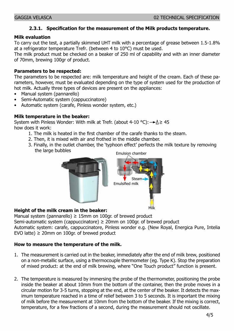
GAGGIA VELASCA 02 TECHNICAL SPECIFICATION
55
How to measure the milk creamThe temperature (Trefr or Tamb) of the milk doesnrsquot affect as much the test result on measuring the milk cream by convection is assumed to always use milk at refrigerator temperature Trefr
Manual systems (Pannarello)Pour 100cc of milk at Trefr in a beaker of 250 ml of capacity and with a inner diameter of 70 mm with machine in steam mode
1 Open the steam knob to discharger water circuit for 4 sec then close the knob 2 Place the beaker with the frother dipped in milk open the steam knob to maximum and start
the chronometer3 After about 30 to 60 seconds close the knob and check the result on milk
Semi-automatic systems (cappuccino)Pours milk at Trefr in a container with the machine in steam mode
1 Open the steam knob to discharge water circuit for 4 sec then close the knob 2 Insert the silicone tube in the milk container placing a beaker of 250 ml capacity and with an
inner diameter of 70 mm under the cappuccino maker and open the steam knob 3 After having provided 100gr of product close the knob and check the result obtained on milk
Note The same applies to machines which have a steam key on the user interface and a sole-noid valve in place of the steam tap
Automatic Carafe Cappuccino Pinless wonder eg(New Royal Energica Pure Intelia EVO Latte) etcAfter setting the machine to delivery of 100gr of product
1 Launch the ldquohot milkrdquo function 2 Collect the product in a beaker with a 250ml of capacity and with an inner diameter of 70 mm
and verify the result obtained on milk Carry out the test using milk at a Trefr
In case the machine allows modify of the emulsion through the menu use the machine with the emulsion set to the default value
Related to the above testing procedure derives the following table of acceptability
Manual Semi-Automatic and Automaticrsquos Milk SystemGrams of Product Minimun Height of the milk cream
ge 130 ge 30mm120 ge 25mm110 ge 22mm100 ge 20mm90 ge 16mm80 ge 13mm70 ge 11mm
NB To verify more accurately the height of the cream a practical expedient dictated by experience is to add to the product just delivered a small amount of coffee The addition of coffee immediately put in evidence the surface of separation between liquid and cream
GAGGIA VELASCA
CHAPTER 3 BRIEF INSTRUCTIONS
GAGGIA VELASCA 03 BRIEF INSTRUCTIONS
16
31 Customer menu Gaggia Velasca CMF
32 Customer menu Gaggia Velasca OTC
Control Panel
Control Panel
Espresso brew button and ESC button
Espresso brew button and ESC button
Long espresso brew button
Long espresso brew button
AROMA STRENGTH but-ton and OK button
AROMA STRENGTH but-ton and OK button
Steam button and UP button
CAPPUCCINO button and UP button
MENU button and DOWN button
SPECIAL DRINKS button and DOWN button
ONOFF button
ONOFF buttonCARAFE QUICK CLEAN button
MENU button
Hot water button
MILK FROTHER button
GAGGIA VELASCA 03 BRIEF INSTRUCTIONS
26
33 Warning icons
34 Troubleshooting
Fill the water tank with fresh water to the MAX level indication
The brew group is not in the machine Insert the group
Remove the coffee grounds container and empty it
- There is too much powder in the brew group Clean the brew group- If an error code is triggered check the section lsquoMeaning of error codesrsquo to see what the code on the display means and what you can do The machine cannot be used when this icon is on the display
You forgot to place the lid on the pre-ground coffee compartment If you do not place it back within 30 seconds the display will return to the main menu and the brewing cycle will be stopped
The bean hopper is empty Put new coffee beans in the bean hopper
Close the service door
Warning signals are displayed in red Below you find a list of the warnings that may appear on the display and their meaning
18 The display shows the following icon to indicate that the machine isheating up
- The machine performs an automatic rinsing cycle19 Remove the container Remove and empty the drip tray SLide the drip
tray back into the machine20 Place the AquaClean lter back in the water tank Reinsert the automatic
milk frother21 Remove and rinse the brew group see chapter lsquoCleaning and
maintenancersquo section lsquoClean the brew grouprsquo
The machine is now ready for use
Interruption of the descaling cycle Once the descaling cycle has started you must complete it till the very endwithout turning o the machine In case you get stuck during the cycle or incase of power failure or accidental disconnection of the power cord youcan exit by pressing the standby button If this occurs empty and rinsecarefully the water tank then ll it up to the CALC CLEAN level Follow theinstructions in chapter lsquoFirst installationrsquo section lsquoManual rinsing cyclersquobefore brewing any beverage If the cycle was not completed the machinewill require another descaling cycle to be performed at your earliestconvenience
Warning icons and error codes Warning signals are displayed in red Below you nd a list of thewarnings that may appear on the display and their meaning- Fill the water tank with fresh water to the MAX level indication
- The bean hopper is empty Put new coee beans in the bean hopper
20 English
- The brew group is not in the machine Insert the group
- Close the service door
- Remove the coee grounds container and empty it
- There is too much powder in the brew group Clean the brew group- If an error code is triggered check the section Meaning of error codes to
see what the code on the display means and what you can do Themachine cannot be used when this icon is on the display
- You forgot to place the lid on the pre-ground coee compartment If youdo not place it back within 30 seconds the display will return to the mainmenu and the brewing cycle will be stopped
Meaning of error codesError code Problem Cause Possible solution
21English
- The brew group is not in the machine Insert the group
- Close the service door
- Remove the coee grounds container and empty it
- There is too much powder in the brew group Clean the brew group- If an error code is triggered check the section Meaning of error codes to
see what the code on the display means and what you can do Themachine cannot be used when this icon is on the display
- You forgot to place the lid on the pre-ground coee compartment If youdo not place it back within 30 seconds the display will return to the mainmenu and the brewing cycle will be stopped
Meaning of error codesError code Problem Cause Possible solution
21English
18 The display shows the following icon to indicate that the machine isheating up
- The machine performs an automatic rinsing cycle19 Remove the container Remove and empty the drip tray SLide the drip
tray back into the machine20 Place the AquaClean lter back in the water tank Reinsert the automatic
milk frother21 Remove and rinse the brew group see chapter lsquoCleaning and
maintenancersquo section lsquoClean the brew grouprsquo
The machine is now ready for use
Interruption of the descaling cycle Once the descaling cycle has started you must complete it till the very endwithout turning o the machine In case you get stuck during the cycle or incase of power failure or accidental disconnection of the power cord youcan exit by pressing the standby button If this occurs empty and rinsecarefully the water tank then ll it up to the CALC CLEAN level Follow theinstructions in chapter lsquoFirst installationrsquo section lsquoManual rinsing cyclersquobefore brewing any beverage If the cycle was not completed the machinewill require another descaling cycle to be performed at your earliestconvenience
Warning icons and error codes Warning signals are displayed in red Below you nd a list of thewarnings that may appear on the display and their meaning- Fill the water tank with fresh water to the MAX level indication
- The bean hopper is empty Put new coee beans in the bean hopper
20 English
- The brew group is not in the machine Insert the group
- Close the service door
- Remove the coee grounds container and empty it
- There is too much powder in the brew group Clean the brew group- If an error code is triggered check the section Meaning of error codes to
see what the code on the display means and what you can do Themachine cannot be used when this icon is on the display
- You forgot to place the lid on the pre-ground coee compartment If youdo not place it back within 30 seconds the display will return to the mainmenu and the brewing cycle will be stopped
Meaning of error codesError code Problem Cause Possible solution
21English
- The brew group is not in the machine Insert the group
- Close the service door
- Remove the coee grounds container and empty it
- There is too much powder in the brew group Clean the brew group- If an error code is triggered check the section Meaning of error codes to
see what the code on the display means and what you can do Themachine cannot be used when this icon is on the display
- You forgot to place the lid on the pre-ground coee compartment If youdo not place it back within 30 seconds the display will return to the mainmenu and the brewing cycle will be stopped
Meaning of error codesError code Problem Cause Possible solution
21English
- The brew group is not in the machine Insert the group
- Close the service door
- Remove the coee grounds container and empty it
- There is too much powder in the brew group Clean the brew group- If an error code is triggered check the section Meaning of error codes to
see what the code on the display means and what you can do Themachine cannot be used when this icon is on the display
- You forgot to place the lid on the pre-ground coee compartment If youdo not place it back within 30 seconds the display will return to the mainmenu and the brewing cycle will be stopped
Meaning of error codesError code Problem Cause Possible solution
21English
Problem Cause Solution
The machine does not switch on
The machine is disconnected orthe main switch is in the OFFposition
Check if the mains cord is insertedcorrectly
Make sure the main switch is set in ON position (AMF-CMF)
The machine is in DEMO mode
The standby button has been pressed for more than 8 seconds
Switch the machine off and then onagain using the main switch on theback of the machine
The drip tray is quickly filled
This is normal The machine useswater to rinse the internal circuit and brew group Some water flows through the internal systemdirectly into the drip tray
Empty the drip tray when the lsquodrip tray fullrsquo full indicator pops up through the drip tray cover
Place a cup under the dispensing spout to collect rinsing water
GAGGIA VELASCA 03 BRIEF INSTRUCTIONS
36
The coffee groundscontainer full icon remains displayed
The coffee grounds container was emptied while the machine was switched off
Always empty the coffee grounds container while the machine is ON Ifthe coffee grounds container is emp-tied while the machine is switched off the coffee cycle counter is not re-set In that case the lsquoempty coffee grounds containerrsquo message will stay on the display even though the con-tainer is not full
The coffee grounds container was placed back too fast
Do not place back the coffee groundscontainer until the screen message prompts you to put it back
The brew group cannot be removed
The brew group is not positioned correctly
Close the maintenance door Switch the machine off and back on again Wait for the machine ready screen toappear and then remove the brew group
The coffee grounds container is not removed
Remove the coffee grounds containerbefore removing the brew group
The machine is still in the descal-ing process
You cannot remove the brew group when the descaling process is active First complete the descaling process and then remove the brew group
The brew group cannot be inserted
The brew group is not in the cor-rect position
The brew group was not put in rest position before it was placed back Make sure that the lever is in contact with the base of the brew group and that the hook of the brew group is in the correct positionReset the machine by switching it on and off Place the drip tray and the coffee grounds container back Leave the brew group out Close the main-tenance door and switch the machine on and off Then try to reinsert the brew group
The coffee has too little cream or is watery
The grinder is set to a coarse setting Adjust the grinder to a finer setting
The brew group is dirtyClean the brew group For thorough cleaning follow the monthly cleaning procedure with the degreasing tablet
The coffee exit duct is dirtyClean the coffee exit duct thoroughly with the handle of the multifunctional tool or a spoon handle
GAGGIA VELASCA 03 BRIEF INSTRUCTIONS
46
The coffee blend is not the correct one Try another coffee blend
The machine is performing its self-adjustment Brew a few cups of coffee
The coffee is not hot enough
The cups you use are cold Preheat the cups by rinsing them withhot water
The temperature is set too low Check the menu settings
Set the temperature to high in the menu
You added milkWhether the milk you add is warm or cold it will always decrease the tem-perature of the coffee to some extent
The machine grinds the coffee beans but coffee does not come out
The grind is set too fine Adjust the grinder to a coarser set-ting
The brew group is dirty Clean the brew group
The coffee dispensing spout is dirty
Clean the coffee dispensing spout andits holes with a pipe cleaner
The coffee exit duct is blockedClean the coffee exit duct with the handle of the multifunctional tool or aspoon handle
The coffee comes out slowly
The grind is ground too finely Change the grinder to a coarser set-ting
The brew group is dirty Clean the brew group
The coffee exit duct is blockedClean the coffee exit duct with the handle of the multifunctional tool or aspoon handle
The machine circuit is blocked by limescale Descale the machine
The milk does not froth
The automatic milk frother is dirty or not assembled or installed cor-rectly
Clean the automatic milk frother and make sure it is correctly assembled orinstalled (AMF-CMF)
The type of milk used is not suita-ble for frothing
Different types of milk result in dif-ferent amounts of froth and different froth qualities Semi-skimmed or full-fat cowrsquos milk give good results
The milk carafe is dirty or not inserted correctly
Clean the carafe and make sure that you position and insert it correctly (OTC)
The milk froth dispensing spout asnot been opened fully
Check that the milk froth dispensing spout has been set in the correct po-sition (OTC)
GAGGIA VELASCA 03 BRIEF INSTRUCTIONS
56
The milk carafe is incompletelyassembled
Check that all the componentshave been assembled correctly (OTC)
The AquaClean fil-ter cannot be ac-tivated as the tick does not appear on the display
A filter has just been activated
You have to dispense at least 10 cups(of 100ml each) before you can ac-tivate a new filter Be careful as you activate a new filter the filter counterwill increase automatically
The filter cannot beactivated and the machine asks for descaling
You have already replaced 8 AquaClean filters After 8 filter replacements you need to descale the machine
Descale your machine first and installthe filter
The filter has not been replaced in time after the AquaClean water filter signal started flashing
Descale your machine first and installthe filter
The filter has not been installed during first installation but after having brewed approx50 coffees (based on 100ml cups) The machine has to be completely limescale-free before installing the AquaClean filter
First descale the machine and then install a new AquaClean filter After descaling the filter counter is reset to 08 Always confirm filter activation inthe machine menu also after filter re-placement
The AquaClean filter was notcorrectly activated during firstinstallation
Follow the instructions on the displayuntil you receive confirmation that thefilter has been activated
The AquaClean fil-ter is installed but the descaling mes-sage appears
After 8 filter replacements you need to descale the machine
First descale the machine and then install a new AquaClean filter This willreset the filter counter to 08 Alwaysconfirm filter activation in the machinemenu also after filter replacement
The descaling mes-sage appears be-fore 8 filters were replaced
You did not activate the Aqua-Clean filter correctly during first installation
First descale the machine and then install a new AquaClean filter Alwaysactivate the filter in the machine menu
You placed the AquaClean filter after having used the machine for a whileYou did not activate the replace-ment filter in the machine menuYou did not replace the filter when the filter symbol started flashing
The filter does not fit
You need to remove air from thefilter Let air bubbles come out of the filter
There is still water in the watertank
Empty the water tank before youinstall the filter
GAGGIA VELASCA 03 BRIEF INSTRUCTIONS
66
You try to install another filter than the AquaClean filter Only the AquaClean filter will fit
There is water un-der the machine
The drip tray is too full and over-flowed
Empty the drip tray when the drip trayfull indicator pops up through the driptray Always empty the drip tray be-fore you start descaling the machine
The machine is not placed on ahorizontal surface
Place the machine on a horizontal surface so that the drop iray full indi-cator works properly
GAGGIA VELASCA
CHAPTER 4 OPERATING LOGIC
Pump
Flow
meter
GAGGIA VELASCA 04 OPERATING LOGIC
17
Wat
er ta
nk
Boile
r
Pum
p
Flow
met
er
Wat
er
disc
harg
eSa
fety
val
ve
Brew
ing
Unit
Stea
m a
nd h
ot w
ater
or m
ilk c
araf
e
Two-
way
sol
enoi
d va
lveW
ater
Ho
t wat
er s
team
41 Water circuit
GAGGIA VELASCA 04 OPERATING LOGIC
27
42 Coffee cycle
Notes Only with Pre-brewing
Switching onWhen the machine is switched on the gear motor repositions itself as follows- It acts on microswitch 1 (see following chapter)- The gear motor changes its rotation direction and moves upwards again by approx 1-2 mm- The boiler begins to heat the water for approx 45 sec at full power in order to reach the
optimal temperature The temperature will then remain at a constant level
Coffee cycle1 The coffee grinder starts the grinding process (controlled by pulses generated by a sensor)2 The gear motor (brewing unit) moves to the brewing position3 Preliminary dispensing phase (short pump activity short pause)4 Product dispensing (the pump operation period is defined by the amount of product dis-
pensed)5 The gear motor moves to its home position (the dregs are expelled automatically)
Main switch ON START STOPTime
Coffee grinder
Heating
Pump
Brewing unit gear motor
Status Heating Ready Coffee cycle
Pulses (Dosage)
Pump operation (flow meter pulses) in
accordance with the amount of product
selected
approx 45 sec
Single microswitch gear motor
StatusMicroswitch OFF ON
GAGGIA VELASCA 04 OPERATING LOGIC
37
43 Single microswitch
Switching onWhen the machine is switched on the gear motor repositions itself as follows- It acts on microswitch 1 - The gear motor changes its rotation direction and moves upwards again by approx 1-2 mm- The boiler begins to heat the water for approx 45 sec at full power in order to reach the optimal
temperature The temperature will then remain at a constant level
An NTC is used as a temperature sensor in the event of overheating this reduces boiler element power consumptionThe electronic system detects the current boiler temperature from the drop in voltage of the sensor and adjusts it accordinglyHeating element values and corresponding temperatures see table
431 Temperature sensor (adjustment)
Temp (degC) R nom (kΩ) ΔR (+- )20 61465 8650 17599 5975 7214 4180 6121 3785 5213 3490 4459 31
100 33 25125 1653 39150 0893 51
The gear motor is powered by a direct current mo-tor that engages with the smaller double toothed wheel using a worm screw The unit is mounted on the axle of the large gear wheel and when a coffee is requested it moves from the standby position to the dispensing position and then back to the standby position again
- Standby position 1
- Dispensing position 2
2
1
GAGGIA VELASCA 04 OPERATING LOGIC
47
45 Autodose system description 230VmA
I0
I0 + 100
I0 + 55
I0 + 200Aroma 45
Aroma 23
Aroma 1
Auto-Zero
100le I0 le300
I0 = current when the BU is moving without load ie without coffee It occurs for example dur-ing the rinsing phase of coffee spout Current targets
Aroma 1 55mAAroma 23 100mAAroma 45 200mA100 mA le I0 le 300 mA
If the BU current is le the current target the grinding timeIf the BU current is ge the current target the grinding time
44 Coffee grinder 230V
The coffee grinder is driven by a direct current motor (1) using a worm screw helicoidal wheel transmission (2)The worm screw (2) drives a plastic gear wheel (3) which turns the lower grinder (4) and the increment pin (5)
23
4
5
1
GAGGIA VELASCA 04 OPERATING LOGIC
57
1) When the system get the stability (ie the system got the current target) the coffee doses should be A1 A23 A45
75 90 10 plusmn15 grams
with medium grinding (500plusmn60μm) and using coffee of test
2) the 3 grinding times are always
T1ltT2ltT3
beside every grinding time is respectively
40s leT3 le10s (10000ms)35s leT2 le9s (9000ms)30s leT1 le81s (8100ms)
DOSE ADJUSTMENT
5 levels Grinder Time
Min Grinder
Time
Max Grinder
TimeCurret target
Aroma of the
grinded product
Aroma1 Very Light T1 3s 81s I0 + 55mAAroma2 Light T2 35s 9s I0 + 100mAAroma3 Med
Aroma4 Strong T3 4s 10s I0 + 200mAAroma5 Very Strong
46 Coffee lack detection and coffee grinder blocked 230V
When the coffee grinder is working the software monitors the current consumption If the current value is very low the machine concludes that coffee is missing if the current value is very high the machine concludes that the coffee grinder is blocked instead if the current value is in the middle the machine concludes that all is ok and it goes on to do the productBecause the current consumption of grinder changes depending on the situations (motor new or old cold or hot etc coffee blends) these current thresholds are not static but dynamic
GAGGIA VELASCA 04 OPERATING LOGIC
67
47 Water level detection (water tank)
ldquoWater lowrdquo message (water reserve)
FunctionThe water level is monitored by a capacitative sensor located one third of the way up the water tank wallIf the electronics assembly detects by means of the sensor that the amount of water in the tank has dropped below the above mentioned level a water reserve remains available for the dispensing process underway (this will cover 200 flow meter pulses)The product dispensing process will then come to an endIf a dispensing cycle ends after the sensor has been triggered (in the reserve) then the display ldquoWater lowrdquo continues to be displayed during the following dispensing cycle
200 puls
Sensor
Water tank
48 Milk Carafe
1) Steam input2)Bring the cappuccino maker into dispensing
position 3) Milk tank
The steam passes through the pipe creating a sucking effect that pulls the milk upwards
Steam
The milk is heated by the steam and taken towards the emulsion chamber where it is mixed with air and transformed into foam
MINUTO 04 OPERATING LOGIC
Page 10
44 Milk Carafe
1) Steam input2)Bring the cappuccino maker into dispensing
position 3) Milk tank
1
2
3
04
The steam passes through the pipe creating a sucking effect that pulls the milk upwards
Steam
The milk is heated by the steam and taken towards the emulsion chamber where it is mixed with air and transformed into foam
GAGGIA VELASCA 04 OPERATING LOGIC
77
49 AquaClean water filter
The AquaClean filter is designed to reduce limescale deposits in the coffee machine and provide filtered water to preserve the aroma and flavor of each cup of coffee By using a series of 8 AquaClean filters there is no need to descale the machine for 5000 cups (It depends both on the type of coffee used rinsing and cleaning programs) We recommend installing the water filter AquaClean the first use of the machine to the maximum before using 5 L of water The machine display will indicate when the filter needs to be replaced The maximum limit is equivalent to 110 L of water The conditions related to the filter work environment (water therefore an active environment for bacteria and microorganisms) require the replacement with a minimum frequency (we suggest 3 months from the activation to ensure the best performance) The filter startsrsquo working from the time is filled with water and continues working even with the machine off It cannot be deactivated manually as it must end its life cycle At the filter activation the display shows the icon with the percentage of use
- Initially 100 then decreasingWhen the autonomy of the current filter becomes less than 8 L of water the display shows
- The icon flashing slowly It means 10 When the autonomy of the current filter becomes less than 2 L of water the display shows
- The icon flashing quickly It means 0 After a maximum of 110 L of water supplied the flashing light turn off and the machine needs to be descaled
GAGGIA VELASCA
CHAPTER 5 SERVICE MODE
GAGGIA VELASCA 05 SERVICE MODE
18
51 Test Mode
IntroductionThis document describes the manual Test Mode of the GAGGIA VELASCA coffee appliance
To enter Test Mode To activate the manual Test Mode the user must press at the same time the ldquoEspressordquo and ldquoMenurdquo (ldquoSpecial Drinksrdquo for OTC version) buttons while connecting the CA to the power supplyOnce entered the Test Mode the first page of seven is shownEntering page the display shows a) The name of the machine and the installed firmware version b) The supply voltage c) The AC supply net frequency detected by the CAPage 1 Keyboard and display colors testing 1) Espresso button 2) Coffee button 3) Steam button (Aroma button for OTC version) 4) Hot Water button (Cappuccino button for OTC version) 5) Aroma button (Milk Froth button for OTC version) 6) Menu button (Special Drinks button for OTC version) 7) Stand-by button 8) Clean button (only OTC version) 9) Menu button (only OTC version)Page 2 Input signals testing a) Water tank sensor b) Door closedopened microswitch c) Coffee Brewing Unit insertion microswitch d) Dreg Drawer insertion microswitchPage 3 Coffee Brewing Unit testing a) UpDown BU movement (24V DC) b) BU effort currentPage 4 Hydraulic circuit loads testing (Pump Electrovalve) a) pump (120-230V AC) b) 2 ways Electrovalve (24Vdc)Page 5 Heater and Grinder testing a) Heater (120-230V AC) b) Grinder (320V DC)Page 6 Autodose quantities a) Light b) Med c) Strong
Test Mode INTELIA EVO V2 AMF
Filename Intelia_EVO2_AMF_TestMode_V05
50 G Divella 12062015 312 revNum Author Verified Approved SaveDate PPP
When accessing the Test Mode all the loads are turned off
11 Entering Page
Used to verify firmware version and some built-in parameters
This page shows the firmware version installed the supply voltage (230V or 120V) and the AC net frequency (50Hz or 60 Hz)
Itrsquos always required to check if the firmware version shown on the display is the same printed on the microcontroller label
Warning If the two version do not match the PCB must be dismissed
Press STEAMThe CA goes to page 1 (KEYB)
Test Mode INTELIA EVO V2 AMF
Filename Intelia_EVO2_AMF_TestMode_V05
50 G Divella 12062015 312 revNum Author Verified Approved SaveDate PPP
When accessing the Test Mode all the loads are turned off
11 Entering Page
Used to verify firmware version and some built-in parameters
This page shows the firmware version installed the supply voltage (230V or 120V) and the AC net frequency (50Hz or 60 Hz)
Itrsquos always required to check if the firmware version shown on the display is the same printed on the microcontroller label
Warning If the two version do not match the PCB must be dismissed
Press STEAMThe CA goes to page 1 (KEYB)
Test Mode INTELIA EVO V2 AMF
Filename Intelia_EVO2_AMF_TestMode_V05
50 G Divella 12062015 312 revNum Author Verified Approved SaveDate PPP
When accessing the Test Mode all the loads are turned off
11 Entering Page
Used to verify firmware version and some built-in parameters
This page shows the firmware version installed the supply voltage (230V or 120V) and the AC net frequency (50Hz or 60 Hz)
Itrsquos always required to check if the firmware version shown on the display is the same printed on the microcontroller label
Warning If the two version do not match the PCB must be dismissed
Press STEAMThe CA goes to page 1 (KEYB)
Test Mode INTELIA EVO V2 AMF
Filename Intelia_EVO2_AMF_TestMode_V05
50 G Divella 12062015 412 revNum Author Verified Approved SaveDate PPP
12 Page 1 (KEYB) Initial condition no button pressed
Press all the buttons from Ndeg1 till Ndeg9Whenever a button is pressed the ldquoONrdquo word appears near the related button number Pressing button Ndeg1 the backlight color switches from WHITE to REDPressing button Ndeg2 the backlight color switches from WHITE to PINK Pressing button Ndeg7 turns the STANDBY LED on To test button Ndeg4 it must be pressed just one time because it causes the CA to navigate to the next page
In case two or more buttons are pressed at the same time the display shows the expression ldquoTWO BTNrdquo This could be a useful warning if the keyboard is not working properly
ERRORS occur if ldquoONrdquo word does not appear or stays fixed on screen In this case itrsquos necessary to check the communication flat cable connected between the keyboard and the CPU-Power board Should not on the other hand change the display color check the JP5 cable
Pressing STEAM button The CA switches to page 2 (INPUTS)
Test Mode INTELIA EVO V2 AMF
Filename Intelia_EVO2_AMF_TestMode_V05
50 G Divella 12062015 412 revNum Author Verified Approved SaveDate PPP
12 Page 1 (KEYB) Initial condition no button pressed
Press all the buttons from Ndeg1 till Ndeg9Whenever a button is pressed the ldquoONrdquo word appears near the related button number Pressing button Ndeg1 the backlight color switches from WHITE to REDPressing button Ndeg2 the backlight color switches from WHITE to PINK Pressing button Ndeg7 turns the STANDBY LED on To test button Ndeg4 it must be pressed just one time because it causes the CA to navigate to the next page
In case two or more buttons are pressed at the same time the display shows the expression ldquoTWO BTNrdquo This could be a useful warning if the keyboard is not working properly
ERRORS occur if ldquoONrdquo word does not appear or stays fixed on screen In this case itrsquos necessary to check the communication flat cable connected between the keyboard and the CPU-Power board Should not on the other hand change the display color check the JP5 cable
Pressing STEAM button The CA switches to page 2 (INPUTS)
Test Mode INTELIA EVO V2 AMF
Filename Intelia_EVO2_AMF_TestMode_V05
50 G Divella 12062015 412 revNum Author Verified Approved SaveDate PPP
12 Page 1 (KEYB) Initial condition no button pressed
Press all the buttons from Ndeg1 till Ndeg9Whenever a button is pressed the ldquoONrdquo word appears near the related button number Pressing button Ndeg1 the backlight color switches from WHITE to REDPressing button Ndeg2 the backlight color switches from WHITE to PINK Pressing button Ndeg7 turns the STANDBY LED on To test button Ndeg4 it must be pressed just one time because it causes the CA to navigate to the next page
In case two or more buttons are pressed at the same time the display shows the expression ldquoTWO BTNrdquo This could be a useful warning if the keyboard is not working properly
ERRORS occur if ldquoONrdquo word does not appear or stays fixed on screen In this case itrsquos necessary to check the communication flat cable connected between the keyboard and the CPU-Power board Should not on the other hand change the display color check the JP5 cable
Pressing STEAM button The CA switches to page 2 (INPUTS)
Test Mode INTELIA EVO V2 AMF
Filename Intelia_EVO2_AMF_TestMode_V05
50 G Divella 12062015 312 revNum Author Verified Approved SaveDate PPP
When accessing the Test Mode all the loads are turned off
11 Entering Page
Used to verify firmware version and some built-in parameters
This page shows the firmware version installed the supply voltage (230V or 120V) and the AC net frequency (50Hz or 60 Hz)
Itrsquos always required to check if the firmware version shown on the display is the same printed on the microcontroller label
Warning If the two version do not match the PCB must be dismissed
Press STEAMThe CA goes to page 1 (KEYB)
GAGGIA VELASCA 05 SERVICE MODE
28
11 Entering Page
12 Page 1 (KEYB)
Verify the firmware version
This page shows the firmware version installed the supply voltage (230V or 120V) and the AC net frequency (50Hz or 60 Hz)
Itrsquos always required to check if the firmware version shown on the display is the same printed on the microcontroller label
WarningIf the two version do not match the PCB must be dismissed
Press STEAM (Press CAPPUCCINO for OTC version)
The CA goes to page 1 (KEYB)
Initial condition no button pressed
Press all the buttons from Ndeg1 till Ndeg9Whenever a button is pressed the ldquoONrdquo word appears near the related button numberPressing button Ndeg1 the backlight color switches from WHITE to REDPressing button Ndeg2 the backlight color switches from WHITE to PINKPressing button Ndeg7 turns the STANDBY LED onTo test button Ndeg4 it must be pressed just one time because it causes the CA to navigate to the next page
In case two or more buttons are pressed at the same time the display shows the expression ldquoTWO BTNrdquo This could be a useful warning if the keyboard is not working properly
ERRORS occur ifldquoONrdquo word does not appear or stays fixed on screen In this case itrsquos necessary to check the communication flat cable connected between the keyboard and the CPU-Power board Should not on the other hand change the display color check the JP5 cable
Test Mode INTELIA EVO V2 AMF
Filename Intelia_EVO2_AMF_TestMode_V05
50 G Divella 12062015 412 revNum Author Verified Approved SaveDate PPP
12 Page 1 (KEYB) Initial condition no button pressed
Press all the buttons from Ndeg1 till Ndeg9Whenever a button is pressed the ldquoONrdquo word appears near the related button number Pressing button Ndeg1 the backlight color switches from WHITE to REDPressing button Ndeg2 the backlight color switches from WHITE to PINK Pressing button Ndeg7 turns the STANDBY LED on To test button Ndeg4 it must be pressed just one time because it causes the CA to navigate to the next page
In case two or more buttons are pressed at the same time the display shows the expression ldquoTWO BTNrdquo This could be a useful warning if the keyboard is not working properly
ERRORS occur if ldquoONrdquo word does not appear or stays fixed on screen In this case itrsquos necessary to check the communication flat cable connected between the keyboard and the CPU-Power board Should not on the other hand change the display color check the JP5 cable
Pressing STEAM button The CA switches to page 2 (INPUTS)
Test Mode INTELIA EVO V2 AMF Filename
Intelia_EVO2_AMF_TestMode_V05
50 G Divella 12062015 512 revNum Author Verified Approved SaveDate PPP
13 Page 2 (INPUTS) Initial condition (having removed all the components)
Insert the tank full of waterThe H2O value must turn from ldquoNrdquo to ldquoYrdquo
ERRORS occur if If the H2O value doesnrsquot change check the capacitive sensor and the related wiring (JP23)
Insert the Dreg DrawerThe DREG value must turn from ldquoNrdquo to ldquoYrdquo
ERRORS occur if If the DREG value doesnrsquot change check the dreg drawer microswitch and the related wiring (JP16)
Close the Side Door (having the dreg drawer already inserted) The DOOR value must turn from ldquoNrdquo to ldquoYrdquo
ERRORS occur if If the DOOR value doesnrsquot change check the side door microswitch and the related wiring (JP14) and verify that the dreg drawer is correctly inserted
Test Mode INTELIA EVO V2 AMF Filename
Intelia_EVO2_AMF_TestMode_V05
50 G Divella 12062015 512 revNum Author Verified Approved SaveDate PPP
13 Page 2 (INPUTS) Initial condition (having removed all the components)
Insert the tank full of waterThe H2O value must turn from ldquoNrdquo to ldquoYrdquo
ERRORS occur if If the H2O value doesnrsquot change check the capacitive sensor and the related wiring (JP23)
Insert the Dreg DrawerThe DREG value must turn from ldquoNrdquo to ldquoYrdquo
ERRORS occur if If the DREG value doesnrsquot change check the dreg drawer microswitch and the related wiring (JP16)
Close the Side Door (having the dreg drawer already inserted) The DOOR value must turn from ldquoNrdquo to ldquoYrdquo
ERRORS occur if If the DOOR value doesnrsquot change check the side door microswitch and the related wiring (JP14) and verify that the dreg drawer is correctly inserted
Test Mode INTELIA EVO V2 AMF Filename
Intelia_EVO2_AMF_TestMode_V05
50 G Divella 12062015 512 revNum Author Verified Approved SaveDate PPP
13 Page 2 (INPUTS) Initial condition (having removed all the components)
Insert the tank full of waterThe H2O value must turn from ldquoNrdquo to ldquoYrdquo
ERRORS occur if If the H2O value doesnrsquot change check the capacitive sensor and the related wiring (JP23)
Insert the Dreg DrawerThe DREG value must turn from ldquoNrdquo to ldquoYrdquo
ERRORS occur if If the DREG value doesnrsquot change check the dreg drawer microswitch and the related wiring (JP16)
Close the Side Door (having the dreg drawer already inserted) The DOOR value must turn from ldquoNrdquo to ldquoYrdquo
ERRORS occur if If the DOOR value doesnrsquot change check the side door microswitch and the related wiring (JP14) and verify that the dreg drawer is correctly inserted Test Mode INTELIA EVO V2 AMF
Filename Intelia_EVO2_AMF_TestMode_V05
50 G Divella 12062015 612 revNum Author Verified Approved SaveDate PPP
Insert the Brewing Unit The BU-P value must turn from ldquoNrdquo to ldquoYrdquo
ERRORS occur if If the BU-P value doesnrsquot change check the BU presence microswitch and the related wiring (JP16)
Test Mode INTELIA EVO V2 AMF
Filename Intelia_EVO2_AMF_TestMode_V05
50 G Divella 12062015 412 revNum Author Verified Approved SaveDate PPP
12 Page 1 (KEYB) Initial condition no button pressed
Press all the buttons from Ndeg1 till Ndeg9Whenever a button is pressed the ldquoONrdquo word appears near the related button number Pressing button Ndeg1 the backlight color switches from WHITE to REDPressing button Ndeg2 the backlight color switches from WHITE to PINK Pressing button Ndeg7 turns the STANDBY LED on To test button Ndeg4 it must be pressed just one time because it causes the CA to navigate to the next page
In case two or more buttons are pressed at the same time the display shows the expression ldquoTWO BTNrdquo This could be a useful warning if the keyboard is not working properly
ERRORS occur if ldquoONrdquo word does not appear or stays fixed on screen In this case itrsquos necessary to check the communication flat cable connected between the keyboard and the CPU-Power board Should not on the other hand change the display color check the JP5 cable
Pressing STEAM button The CA switches to page 2 (INPUTS)
GAGGIA VELASCA 05 SERVICE MODE
38
13 Page 2 (INPUTS)
Insert the tank full of water
The H2O value must turn from ldquoNrdquo to ldquoYrdquo
ERRORS occur ifIf the H2O value doesnrsquot change check the capacitive sensor and the re-lated wiring (JP23)
Insert the Dreg Drawer
The DREG value must turn from ldquoNrdquo to ldquoYrdquo
ERRORS occur ifIf the DREG value doesnrsquot change check the dreg drawer microswitch and the related wiring (JP16)
Close the Side Door (having the dreg drawer already inserted)
The DOOR value must turn from ldquoNrdquo to ldquoYrdquo
ERRORS occur ifIf the DOOR value doesnrsquot change check the side door microswitch and the related wiring (JP14) and verify that the dreg drawer is correctly in-serted
Insert the Brewing Unit
The BU-P value must turn from ldquoNrdquo to ldquoYrdquo
ERRORS occur ifIf the BU-P value doesnrsquot change check the BU presence microswitch and the related wiring (JP16)
Initial condition (having removed all the components)
The CA switches to page 2 (INPUTS)
Pressing STEAM button (Press CAPPUCCINO for OTC version)
Test Mode INTELIA EVO V2 AMF Filename
Intelia_EVO2_AMF_TestMode_V05
50 G Divella 12062015 712 revNum Author Verified Approved SaveDate PPP
14 Page 3 (BU)
Initial condition
Press the ESPRESSO button to conduct the BU to the Work position When the BU reaches the work position the value WORK turns from ldquoNrdquo to ldquoYrdquo The absorbed BU current must be less than 200mA if the BU is not inserted and less than 300mA if the BU is inserted
ERRORS occur if The WORK value stays fixed on ldquoNrdquo while the backlight turns RED from WHITE in this case check the microswitch the BU engine (could be blocked) and finally the JP16 and JP14 wirings
ERROR (BU not inserted) If the absorbed current is more than 200 mA the display backlight turns red In this case check the gears of the engine and its standing in the housing
ERROR (BU inserted)If the absorbed current is more than 300 mA the display backlight turns red In this case check the gears of the engine and its standing in the housing
Test Mode INTELIA EVO V2 AMF Filename
Intelia_EVO2_AMF_TestMode_V05
50 G Divella 12062015 712 revNum Author Verified Approved SaveDate PPP
14 Page 3 (BU)
Initial condition
Press the ESPRESSO button to conduct the BU to the Work position When the BU reaches the work position the value WORK turns from ldquoNrdquo to ldquoYrdquo The absorbed BU current must be less than 200mA if the BU is not inserted and less than 300mA if the BU is inserted
ERRORS occur if The WORK value stays fixed on ldquoNrdquo while the backlight turns RED from WHITE in this case check the microswitch the BU engine (could be blocked) and finally the JP16 and JP14 wirings
ERROR (BU not inserted) If the absorbed current is more than 200 mA the display backlight turns red In this case check the gears of the engine and its standing in the housing
ERROR (BU inserted)If the absorbed current is more than 300 mA the display backlight turns red In this case check the gears of the engine and its standing in the housing
Test Mode INTELIA EVO V2 AMF Filename
Intelia_EVO2_AMF_TestMode_V05
50 G Divella 12062015 712 revNum Author Verified Approved SaveDate PPP
14 Page 3 (BU)
Initial condition
Press the ESPRESSO button to conduct the BU to the Work position When the BU reaches the work position the value WORK turns from ldquoNrdquo to ldquoYrdquo The absorbed BU current must be less than 200mA if the BU is not inserted and less than 300mA if the BU is inserted
ERRORS occur if The WORK value stays fixed on ldquoNrdquo while the backlight turns RED from WHITE in this case check the microswitch the BU engine (could be blocked) and finally the JP16 and JP14 wirings
ERROR (BU not inserted) If the absorbed current is more than 200 mA the display backlight turns red In this case check the gears of the engine and its standing in the housing
ERROR (BU inserted)If the absorbed current is more than 300 mA the display backlight turns red In this case check the gears of the engine and its standing in the housing
Test Mode INTELIA EVO V2 AMF Filename
Intelia_EVO2_AMF_TestMode_V05
50 G Divella 12062015 712 revNum Author Verified Approved SaveDate PPP
14 Page 3 (BU)
Initial condition
Press the ESPRESSO button to conduct the BU to the Work position When the BU reaches the work position the value WORK turns from ldquoNrdquo to ldquoYrdquo The absorbed BU current must be less than 200mA if the BU is not inserted and less than 300mA if the BU is inserted
ERRORS occur if The WORK value stays fixed on ldquoNrdquo while the backlight turns RED from WHITE in this case check the microswitch the BU engine (could be blocked) and finally the JP16 and JP14 wirings
ERROR (BU not inserted) If the absorbed current is more than 200 mA the display backlight turns red In this case check the gears of the engine and its standing in the housing
ERROR (BU inserted)If the absorbed current is more than 300 mA the display backlight turns red In this case check the gears of the engine and its standing in the housing
Test Mode INTELIA EVO V2 AMF Filename
Intelia_EVO2_AMF_TestMode_V05
50 G Divella 12062015 712 revNum Author Verified Approved SaveDate PPP
14 Page 3 (BU)
Initial condition
Press the ESPRESSO button to conduct the BU to the Work position When the BU reaches the work position the value WORK turns from ldquoNrdquo to ldquoYrdquo The absorbed BU current must be less than 200mA if the BU is not inserted and less than 300mA if the BU is inserted
ERRORS occur if The WORK value stays fixed on ldquoNrdquo while the backlight turns RED from WHITE in this case check the microswitch the BU engine (could be blocked) and finally the JP16 and JP14 wirings
ERROR (BU not inserted) If the absorbed current is more than 200 mA the display backlight turns red In this case check the gears of the engine and its standing in the housing
ERROR (BU inserted)If the absorbed current is more than 300 mA the display backlight turns red In this case check the gears of the engine and its standing in the housing
Test Mode INTELIA EVO V2 AMF Filename
Intelia_EVO2_AMF_TestMode_V05
50 G Divella 12062015 812 revNum Author Verified Approved SaveDate PPP
Press the COFFEE button to move the BU towards the HOME position When the BU reaches the HOME position the HOME value changes from ldquoNrdquo to ldquoYrdquo The maximum absorbed current must be less than 200 mA (BU not inserted) 300 mA (BU inserted)
ERRORS occur if The HOME value stays fixed on ldquoNrdquo while the backlight turns RED from WHITE in this case check the microswitch the BU engine (could be blocked) and finally the JP16 and JP14 wirings
ERROR (BU not inserted) If the absorbed current is more than 200 mA the display backlight turns red In this case check the gears of the engine and its standing in the housing
ERROR (BU inserted)If the absorbed current is more than 300 mA the display backlight turns red In this case check the gears of the engine and its standing in the housing
Press the STEAM button The CA goes to the EVPUMP page (EV - PUMP)
Test Mode INTELIA EVO V2 AMF Filename
Intelia_EVO2_AMF_TestMode_V05
50 G Divella 12062015 812 revNum Author Verified Approved SaveDate PPP
Press the COFFEE button to move the BU towards the HOME position When the BU reaches the HOME position the HOME value changes from ldquoNrdquo to ldquoYrdquo The maximum absorbed current must be less than 200 mA (BU not inserted) 300 mA (BU inserted)
ERRORS occur if The HOME value stays fixed on ldquoNrdquo while the backlight turns RED from WHITE in this case check the microswitch the BU engine (could be blocked) and finally the JP16 and JP14 wirings
ERROR (BU not inserted) If the absorbed current is more than 200 mA the display backlight turns red In this case check the gears of the engine and its standing in the housing
ERROR (BU inserted)If the absorbed current is more than 300 mA the display backlight turns red In this case check the gears of the engine and its standing in the housing
Press the STEAM button The CA goes to the EVPUMP page (EV - PUMP)
Test Mode INTELIA EVO V2 AMF Filename
Intelia_EVO2_AMF_TestMode_V05
50 G Divella 12062015 812 revNum Author Verified Approved SaveDate PPP
Press the COFFEE button to move the BU towards the HOME position When the BU reaches the HOME position the HOME value changes from ldquoNrdquo to ldquoYrdquo The maximum absorbed current must be less than 200 mA (BU not inserted) 300 mA (BU inserted)
ERRORS occur if The HOME value stays fixed on ldquoNrdquo while the backlight turns RED from WHITE in this case check the microswitch the BU engine (could be blocked) and finally the JP16 and JP14 wirings
ERROR (BU not inserted) If the absorbed current is more than 200 mA the display backlight turns red In this case check the gears of the engine and its standing in the housing
ERROR (BU inserted)If the absorbed current is more than 300 mA the display backlight turns red In this case check the gears of the engine and its standing in the housing
Press the STEAM button The CA goes to the EVPUMP page (EV - PUMP)
Test Mode INTELIA EVO V2 AMF Filename
Intelia_EVO2_AMF_TestMode_V05
50 G Divella 12062015 812 revNum Author Verified Approved SaveDate PPP
Press the COFFEE button to move the BU towards the HOME position When the BU reaches the HOME position the HOME value changes from ldquoNrdquo to ldquoYrdquo The maximum absorbed current must be less than 200 mA (BU not inserted) 300 mA (BU inserted)
ERRORS occur if The HOME value stays fixed on ldquoNrdquo while the backlight turns RED from WHITE in this case check the microswitch the BU engine (could be blocked) and finally the JP16 and JP14 wirings
ERROR (BU not inserted) If the absorbed current is more than 200 mA the display backlight turns red In this case check the gears of the engine and its standing in the housing
ERROR (BU inserted)If the absorbed current is more than 300 mA the display backlight turns red In this case check the gears of the engine and its standing in the housing
Press the STEAM button The CA goes to the EVPUMP page (EV - PUMP)
Test Mode INTELIA EVO V2 AMF Filename
Intelia_EVO2_AMF_TestMode_V05
50 G Divella 12062015 812 revNum Author Verified Approved SaveDate PPP
Press the COFFEE button to move the BU towards the HOME position When the BU reaches the HOME position the HOME value changes from ldquoNrdquo to ldquoYrdquo The maximum absorbed current must be less than 200 mA (BU not inserted) 300 mA (BU inserted)
ERRORS occur if The HOME value stays fixed on ldquoNrdquo while the backlight turns RED from WHITE in this case check the microswitch the BU engine (could be blocked) and finally the JP16 and JP14 wirings
ERROR (BU not inserted) If the absorbed current is more than 200 mA the display backlight turns red In this case check the gears of the engine and its standing in the housing
ERROR (BU inserted)If the absorbed current is more than 300 mA the display backlight turns red In this case check the gears of the engine and its standing in the housing
Press the STEAM button The CA goes to the EVPUMP page (EV - PUMP)
GAGGIA VELASCA 05 SERVICE MODE
48
14 Page 3 (BU)
Press the ESPRESSO button to conduct the BU to the Work position
When the BU reaches the work position the value WORK turns from ldquoNrdquo to ldquoYrdquo The absorbed BU current must be less than 200mA if the BU is not inserted and less than 300mA if the BU is inserted
ERRORS occur ifThe WORK value stays fixed on ldquoNrdquo while the backlight turns RED from WHITE in this case check the microswitch the BU engine (could be blocked) and finally the JP16 and JP14 wiringsERROR (BU not inserted)If the absorbed current is more than 200 mA the display backlight turns red In this case check the gears of the engine and its standing in the housingERROR (BU inserted)If the absorbed current is more than 300 mA the display backlight turns red In this case check the gears of the engine and its standing in the housing
Press the COFFEE button to move the BU towards the HOME position
When the BU reaches the HOME position the HOME value changes from ldquoNrdquo to ldquoYrdquo The maximum absorbed current must be less than 200 mA (BU not inserted) 300 mA (BU inserted)
ERRORS occur ifThe HOME value stays fixed on ldquoNrdquo while the backlight turns RED from WHITE in this case check the microswitch the BU engine (could be blocked) and finally the JP16 and JP14 wiringsERROR (BU not inserted)If the absorbed current is more than 200 mA the display backlight turns red In this case check the gears of the engine and its standing in the housingERROR (BU inserted)If the absorbed current is more than 300 mA the display backlight turns red In this case check the gears of the engine and its standing in the housing
Press the STEAM button (Press CAPPUCCINO for OTC version)
The CA goes to the EVPUMP page (EV - PUMP)
Initial condition
Test Mode INTELIA EVO V2 AMF Filename
Intelia_EVO2_AMF_TestMode_V05
50 G Divella 12062015 912 revNum Author Verified Approved SaveDate PPP
15 Page 4 (EV - PUMP)
Should this page been shown it means either the dreg drawer is not correctly inserted or the side door not closed Only solving both these issues it would be possible to come out from this screen
Press the ESPRESSO button to activate the 2-ways Electrovalve (closed by default) The Electrovalve is activated so the EV1 value turns from ldquoOFFrdquo to ldquoONrdquo
Press the HOT WATER button to activate the PumpThe water now flows out from the spout causing the update of the IMP value with the number of flowmeter impulses The LH value must stay within 10lh and 18 lh
ERROR If the number of impulses remains 0 and the display backlight turns red it means that therersquos an error in the hydraulic circuit If water comes out from the spout it means that therersquos an error in the flowmeter or in its wiring to the CPUPOWER (JP5) if on the other hand no water comes out itrsquos necessary to check the pump or the hydraulic circuit or the pump wiring (JP24)
Press the STEAM WATER button The CA shows the HeaterGrinder page (Heater-Grinder)
16 Page5 (Heater-Grinder)
Test Mode INTELIA EVO V2 AMF Filename
Intelia_EVO2_AMF_TestMode_V05
50 G Divella 12062015 912 revNum Author Verified Approved SaveDate PPP
15 Page 4 (EV - PUMP)
Should this page been shown it means either the dreg drawer is not correctly inserted or the side door not closed Only solving both these issues it would be possible to come out from this screen
Press the ESPRESSO button to activate the 2-ways Electrovalve (closed by default) The Electrovalve is activated so the EV1 value turns from ldquoOFFrdquo to ldquoONrdquo
Press the HOT WATER button to activate the PumpThe water now flows out from the spout causing the update of the IMP value with the number of flowmeter impulses The LH value must stay within 10lh and 18 lh
ERROR If the number of impulses remains 0 and the display backlight turns red it means that therersquos an error in the hydraulic circuit If water comes out from the spout it means that therersquos an error in the flowmeter or in its wiring to the CPUPOWER (JP5) if on the other hand no water comes out itrsquos necessary to check the pump or the hydraulic circuit or the pump wiring (JP24)
Press the STEAM WATER button The CA shows the HeaterGrinder page (Heater-Grinder)
16 Page5 (Heater-Grinder)
Test Mode INTELIA EVO V2 AMF Filename
Intelia_EVO2_AMF_TestMode_V05
50 G Divella 12062015 912 revNum Author Verified Approved SaveDate PPP
15 Page 4 (EV - PUMP)
Should this page been shown it means either the dreg drawer is not correctly inserted or the side door not closed Only solving both these issues it would be possible to come out from this screen
Press the ESPRESSO button to activate the 2-ways Electrovalve (closed by default) The Electrovalve is activated so the EV1 value turns from ldquoOFFrdquo to ldquoONrdquo
Press the HOT WATER button to activate the PumpThe water now flows out from the spout causing the update of the IMP value with the number of flowmeter impulses The LH value must stay within 10lh and 18 lh
ERROR If the number of impulses remains 0 and the display backlight turns red it means that therersquos an error in the hydraulic circuit If water comes out from the spout it means that therersquos an error in the flowmeter or in its wiring to the CPUPOWER (JP5) if on the other hand no water comes out itrsquos necessary to check the pump or the hydraulic circuit or the pump wiring (JP24)
Press the STEAM WATER button The CA shows the HeaterGrinder page (Heater-Grinder)
16 Page5 (Heater-Grinder)
Test Mode INTELIA EVO V2 AMF Filename
Intelia_EVO2_AMF_TestMode_V05
50 G Divella 12062015 912 revNum Author Verified Approved SaveDate PPP
15 Page 4 (EV - PUMP)
Should this page been shown it means either the dreg drawer is not correctly inserted or the side door not closed Only solving both these issues it would be possible to come out from this screen
Press the ESPRESSO button to activate the 2-ways Electrovalve (closed by default) The Electrovalve is activated so the EV1 value turns from ldquoOFFrdquo to ldquoONrdquo
Press the HOT WATER button to activate the PumpThe water now flows out from the spout causing the update of the IMP value with the number of flowmeter impulses The LH value must stay within 10lh and 18 lh
ERROR If the number of impulses remains 0 and the display backlight turns red it means that therersquos an error in the hydraulic circuit If water comes out from the spout it means that therersquos an error in the flowmeter or in its wiring to the CPUPOWER (JP5) if on the other hand no water comes out itrsquos necessary to check the pump or the hydraulic circuit or the pump wiring (JP24)
Press the STEAM WATER button The CA shows the HeaterGrinder page (Heater-Grinder)
16 Page5 (Heater-Grinder)
Test Mode INTELIA EVO V2 AMF Filename
Intelia_EVO2_AMF_TestMode_V05
50 G Divella 12062015 912 revNum Author Verified Approved SaveDate PPP
15 Page 4 (EV - PUMP)
Should this page been shown it means either the dreg drawer is not correctly inserted or the side door not closed Only solving both these issues it would be possible to come out from this screen
Press the ESPRESSO button to activate the 2-ways Electrovalve (closed by default) The Electrovalve is activated so the EV1 value turns from ldquoOFFrdquo to ldquoONrdquo
Press the HOT WATER button to activate the PumpThe water now flows out from the spout causing the update of the IMP value with the number of flowmeter impulses The LH value must stay within 10lh and 18 lh
ERROR If the number of impulses remains 0 and the display backlight turns red it means that therersquos an error in the hydraulic circuit If water comes out from the spout it means that therersquos an error in the flowmeter or in its wiring to the CPUPOWER (JP5) if on the other hand no water comes out itrsquos necessary to check the pump or the hydraulic circuit or the pump wiring (JP24)
Press the STEAM WATER button The CA shows the HeaterGrinder page (Heater-Grinder)
16 Page5 (Heater-Grinder)
Test Mode INTELIA EVO V2 AMF Filename
Intelia_EVO2_AMF_TestMode_V05
50 G Divella 12062015 912 revNum Author Verified Approved SaveDate PPP
15 Page 4 (EV - PUMP)
Should this page been shown it means either the dreg drawer is not correctly inserted or the side door not closed Only solving both these issues it would be possible to come out from this screen
Press the ESPRESSO button to activate the 2-ways Electrovalve (closed by default) The Electrovalve is activated so the EV1 value turns from ldquoOFFrdquo to ldquoONrdquo
Press the HOT WATER button to activate the PumpThe water now flows out from the spout causing the update of the IMP value with the number of flowmeter impulses The LH value must stay within 10lh and 18 lh
ERROR If the number of impulses remains 0 and the display backlight turns red it means that therersquos an error in the hydraulic circuit If water comes out from the spout it means that therersquos an error in the flowmeter or in its wiring to the CPUPOWER (JP5) if on the other hand no water comes out itrsquos necessary to check the pump or the hydraulic circuit or the pump wiring (JP24)
Press the STEAM WATER button The CA shows the HeaterGrinder page (Heater-Grinder)
16 Page5 (Heater-Grinder)
Test Mode INTELIA EVO V2 AMF Filename
Intelia_EVO2_AMF_TestMode_V05
50 G Divella 12062015 1012 revNum Author Verified Approved SaveDate PPP
Initial condition
Press the HOT WATER button to activate the GrinderThe coffee grinder starts milling for 5000 ms if the user doesnrsquot release the button before In this case the activation time is shown in the red-circled field of the picture
ERROR If this number keeps fixed at 0 the display turns red and the engine moves then there must be a fault in the grinder wiring (JP8) or in the grinder itself
Keep pressed STANDBY for 5 secs to reset grinder parameters Pressing button STANDBY for 5 secs resets grinder parameters
Test Mode INTELIA EVO V2 AMF Filename
Intelia_EVO2_AMF_TestMode_V05
50 G Divella 12062015 1012 revNum Author Verified Approved SaveDate PPP
Initial condition
Press the HOT WATER button to activate the GrinderThe coffee grinder starts milling for 5000 ms if the user doesnrsquot release the button before In this case the activation time is shown in the red-circled field of the picture
ERROR If this number keeps fixed at 0 the display turns red and the engine moves then there must be a fault in the grinder wiring (JP8) or in the grinder itself
Keep pressed STANDBY for 5 secs to reset grinder parameters Pressing button STANDBY for 5 secs resets grinder parameters
Test Mode INTELIA EVO V2 AMF Filename
Intelia_EVO2_AMF_TestMode_V05
50 G Divella 12062015 1012 revNum Author Verified Approved SaveDate PPP
Initial condition
Press the HOT WATER button to activate the GrinderThe coffee grinder starts milling for 5000 ms if the user doesnrsquot release the button before In this case the activation time is shown in the red-circled field of the picture
ERROR If this number keeps fixed at 0 the display turns red and the engine moves then there must be a fault in the grinder wiring (JP8) or in the grinder itself
Keep pressed STANDBY for 5 secs to reset grinder parameters Pressing button STANDBY for 5 secs resets grinder parameters
GAGGIA VELASCA 05 SERVICE MODE
58
15 Page 4 (EV - PUMP)
Press the ESPRESSO button to activate the 2-ways Electrovalve (closed by default)
The Electrovalve is activated so the EV1 value turns from ldquoOFFrdquo to ldquoONrdquo
Press the HOT WATER (Press MILK for OTC version) button to activate the Pump
The water now flows out from the spout causing the update of the IMP value with the number of flowmeter impulses The LH value must stay within 10lh and 18 lh
ERRORIf the number of impulses remains 0 and the display backlight turns red it means that therersquos an error in the hydraulic circuit If water comes out from the spout it means that therersquos an error in the flowmeter or in its wiring to the CPUPOWER (JP5) if on the other hand no water comes out itrsquos necessary to check the pump or the hydraulic circuit or the pump wiring (JP24)
Press the STEAM WATER button (Press CAPPUCCINO for OTC version)
The CA shows the HeaterGrinder page (Heater-Grinder)
Initial condition
Press the HOT WATER (Press MILK for OTC version) button to activate the Grinder
The coffee grinder starts milling for 5000 ms In this case the activation time is shown in the red-circled field of the picture
ERRORIf this number keeps fixed at 0or the grinder does not run the display turns red this means there must be a fault in the grinder wiring (JP8) or in the grinder itself or in the electronic board
Keep pressed STANDBY for 5 secs to reset grinder parameters
Pressing button STANDBY for 5 secs resets grinder parametersThis action is needed if the grinder has been replaced
Should this page been shown it means either the dreg drawer is not cor-rectly inserted or the side door not closed Only solving both these issues it would be possible to come out from this screen
16 Page 5 (Heater-Grinder)
Test Mode INTELIA EVO V2 AMF Filename
Intelia_EVO2_AMF_TestMode_V05
50 G Divella 12062015 1112 revNum Author Verified Approved SaveDate PPP
Heater Temperature monitoring The red-circled number shows the heater temperature in Celsius degrees
ERROR If inside the HEATER column appears the word ldquoSHORTrdquo then the NTC sensor is in a short-circuit state The display backlight turns RED from WHITE in this case the NTC wiring or the input CPUPOWER (JP13) must be checked
ERROR If inside the HEATER column appears the word ldquoOPENrdquo then the NTC sensor is disconnected The display backlight turns RED from WHITE In this case the connectivity of the NTC wiring to the CPUPOWER (JP13) must be checked
Press the COFFEE button to activate the heaterThe label switches from ldquoOFFrdquo to ldquoONrdquo and the number indicating the temperature starts to increase (and so the current absorbed by the CA on the power supply ndash ca 8 A 230V) For safety reasons it is possible to activate the heater keeping pressed the button for a maximum time of 5 seconds
Therersquos a further check on the temperature level should it rise over 120degC the display backlight turns pink and an alarm message appears In this scenario the heater is forced to stay turned off to avoid dangerous over-temperatures
ERROR If therersquos no temperature increasing the user must check the heater resistance its wiring to the CPUPOWER (JP19) and also the NTC wiring (JP13)
Press both the AROMA and the MENU buttons These values appear on the display
Grinding time applied during last mill Average of the low state duration of the current sensor
signal Threshold for the presenceabsence coffee detection
Test Mode INTELIA EVO V2 AMF Filename
Intelia_EVO2_AMF_TestMode_V05
50 G Divella 12062015 1112 revNum Author Verified Approved SaveDate PPP
Heater Temperature monitoring The red-circled number shows the heater temperature in Celsius degrees
ERROR If inside the HEATER column appears the word ldquoSHORTrdquo then the NTC sensor is in a short-circuit state The display backlight turns RED from WHITE in this case the NTC wiring or the input CPUPOWER (JP13) must be checked
ERROR If inside the HEATER column appears the word ldquoOPENrdquo then the NTC sensor is disconnected The display backlight turns RED from WHITE In this case the connectivity of the NTC wiring to the CPUPOWER (JP13) must be checked
Press the COFFEE button to activate the heaterThe label switches from ldquoOFFrdquo to ldquoONrdquo and the number indicating the temperature starts to increase (and so the current absorbed by the CA on the power supply ndash ca 8 A 230V) For safety reasons it is possible to activate the heater keeping pressed the button for a maximum time of 5 seconds
Therersquos a further check on the temperature level should it rise over 120degC the display backlight turns pink and an alarm message appears In this scenario the heater is forced to stay turned off to avoid dangerous over-temperatures
ERROR If therersquos no temperature increasing the user must check the heater resistance its wiring to the CPUPOWER (JP19) and also the NTC wiring (JP13)
Press both the AROMA and the MENU buttons These values appear on the display
Grinding time applied during last mill Average of the low state duration of the current sensor
signal Threshold for the presenceabsence coffee detection
Test Mode INTELIA EVO V2 AMF Filename
Intelia_EVO2_AMF_TestMode_V05
50 G Divella 12062015 1112 revNum Author Verified Approved SaveDate PPP
Heater Temperature monitoring The red-circled number shows the heater temperature in Celsius degrees
ERROR If inside the HEATER column appears the word ldquoSHORTrdquo then the NTC sensor is in a short-circuit state The display backlight turns RED from WHITE in this case the NTC wiring or the input CPUPOWER (JP13) must be checked
ERROR If inside the HEATER column appears the word ldquoOPENrdquo then the NTC sensor is disconnected The display backlight turns RED from WHITE In this case the connectivity of the NTC wiring to the CPUPOWER (JP13) must be checked
Press the COFFEE button to activate the heaterThe label switches from ldquoOFFrdquo to ldquoONrdquo and the number indicating the temperature starts to increase (and so the current absorbed by the CA on the power supply ndash ca 8 A 230V) For safety reasons it is possible to activate the heater keeping pressed the button for a maximum time of 5 seconds
Therersquos a further check on the temperature level should it rise over 120degC the display backlight turns pink and an alarm message appears In this scenario the heater is forced to stay turned off to avoid dangerous over-temperatures
ERROR If therersquos no temperature increasing the user must check the heater resistance its wiring to the CPUPOWER (JP19) and also the NTC wiring (JP13)
Press both the AROMA and the MENU buttons These values appear on the display
Grinding time applied during last mill Average of the low state duration of the current sensor
signal Threshold for the presenceabsence coffee detection
Test Mode INTELIA EVO V2 AMF Filename
Intelia_EVO2_AMF_TestMode_V05
50 G Divella 12062015 1112 revNum Author Verified Approved SaveDate PPP
Heater Temperature monitoring The red-circled number shows the heater temperature in Celsius degrees
ERROR If inside the HEATER column appears the word ldquoSHORTrdquo then the NTC sensor is in a short-circuit state The display backlight turns RED from WHITE in this case the NTC wiring or the input CPUPOWER (JP13) must be checked
ERROR If inside the HEATER column appears the word ldquoOPENrdquo then the NTC sensor is disconnected The display backlight turns RED from WHITE In this case the connectivity of the NTC wiring to the CPUPOWER (JP13) must be checked
Press the COFFEE button to activate the heaterThe label switches from ldquoOFFrdquo to ldquoONrdquo and the number indicating the temperature starts to increase (and so the current absorbed by the CA on the power supply ndash ca 8 A 230V) For safety reasons it is possible to activate the heater keeping pressed the button for a maximum time of 5 seconds
Therersquos a further check on the temperature level should it rise over 120degC the display backlight turns pink and an alarm message appears In this scenario the heater is forced to stay turned off to avoid dangerous over-temperatures
ERROR If therersquos no temperature increasing the user must check the heater resistance its wiring to the CPUPOWER (JP19) and also the NTC wiring (JP13)
Press both the AROMA and the MENU buttons These values appear on the display
Grinding time applied during last mill Average of the low state duration of the current sensor
signal Threshold for the presenceabsence coffee detection
Test Mode INTELIA EVO V2 AMF Filename
Intelia_EVO2_AMF_TestMode_V05
50 G Divella 12062015 1112 revNum Author Verified Approved SaveDate PPP
Heater Temperature monitoring The red-circled number shows the heater temperature in Celsius degrees
ERROR If inside the HEATER column appears the word ldquoSHORTrdquo then the NTC sensor is in a short-circuit state The display backlight turns RED from WHITE in this case the NTC wiring or the input CPUPOWER (JP13) must be checked
ERROR If inside the HEATER column appears the word ldquoOPENrdquo then the NTC sensor is disconnected The display backlight turns RED from WHITE In this case the connectivity of the NTC wiring to the CPUPOWER (JP13) must be checked
Press the COFFEE button to activate the heaterThe label switches from ldquoOFFrdquo to ldquoONrdquo and the number indicating the temperature starts to increase (and so the current absorbed by the CA on the power supply ndash ca 8 A 230V) For safety reasons it is possible to activate the heater keeping pressed the button for a maximum time of 5 seconds
Therersquos a further check on the temperature level should it rise over 120degC the display backlight turns pink and an alarm message appears In this scenario the heater is forced to stay turned off to avoid dangerous over-temperatures
ERROR If therersquos no temperature increasing the user must check the heater resistance its wiring to the CPUPOWER (JP19) and also the NTC wiring (JP13)
Press both the AROMA and the MENU buttons These values appear on the display
Grinding time applied during last mill Average of the low state duration of the current sensor
signal Threshold for the presenceabsence coffee detection
Test Mode INTELIA EVO V2 AMF Filename
Intelia_EVO2_AMF_TestMode_V05
50 G Divella 12062015 1112 revNum Author Verified Approved SaveDate PPP
Heater Temperature monitoring The red-circled number shows the heater temperature in Celsius degrees
ERROR If inside the HEATER column appears the word ldquoSHORTrdquo then the NTC sensor is in a short-circuit state The display backlight turns RED from WHITE in this case the NTC wiring or the input CPUPOWER (JP13) must be checked
ERROR If inside the HEATER column appears the word ldquoOPENrdquo then the NTC sensor is disconnected The display backlight turns RED from WHITE In this case the connectivity of the NTC wiring to the CPUPOWER (JP13) must be checked
Press the COFFEE button to activate the heaterThe label switches from ldquoOFFrdquo to ldquoONrdquo and the number indicating the temperature starts to increase (and so the current absorbed by the CA on the power supply ndash ca 8 A 230V) For safety reasons it is possible to activate the heater keeping pressed the button for a maximum time of 5 seconds
Therersquos a further check on the temperature level should it rise over 120degC the display backlight turns pink and an alarm message appears In this scenario the heater is forced to stay turned off to avoid dangerous over-temperatures
ERROR If therersquos no temperature increasing the user must check the heater resistance its wiring to the CPUPOWER (JP19) and also the NTC wiring (JP13)
Press both the AROMA and the MENU buttons These values appear on the display
Grinding time applied during last mill Average of the low state duration of the current sensor
signal Threshold for the presenceabsence coffee detection
Test Mode INTELIA EVO V2 AMF Filename
Intelia_EVO2_AMF_TestMode_V05
50 G Divella 12062015 1212 revNum Author Verified Approved SaveDate PPP
Press the STEAM button The CA shows the Autodoses page
17 Page 6 (Autodoses) The CA shows the AUTODOSES page with the time of milling for the different coffee aroma
Light Med Strong
Test Mode INTELIA EVO V2 AMF Filename
Intelia_EVO2_AMF_TestMode_V05
50 G Divella 12062015 1212 revNum Author Verified Approved SaveDate PPP
Press the STEAM button The CA shows the Autodoses page
17 Page 6 (Autodoses) The CA shows the AUTODOSES page with the time of milling for the different coffee aroma
Light Med Strong
GAGGIA VELASCA 05 SERVICE MODE
68
Heater Temperature monitoring
The red-circled number shows the heater temperature in Celsius degrees
ERRORIf inside the HEATER column appears the word ldquoSHORTrdquo then the NTC sensor is in a short-circuit state The display backlight turns RED from WHITE in this case the NTC wiring or the input CPUPOWER (JP13) must be checkedERRORIf inside the HEATER column appears the word ldquoOPENrdquo then the NTC sensor is disconnected The display backlight turns RED from WHITE In this case the connectivity of the NTC wiring to the CPUPOWER (JP13) must be checked
Press the COFFEE button to activate the heaterThe label switches from ldquoOFFrdquo to ldquoONrdquo and the number indicating the temperature starts to increase (and so the current absorbed by the CA on the power supply ndash ca 8 A 230V)For safety reasons it is possible to activate the heater keeping pressed the button for a maximum time of 5 secondsTherersquos a further check on the temperature level should it rise over 120degC the display backlight turns pink and an alarm message appears In this scenario the heater is forced to stay turned off to avoid dangerous over-temperatures
ERRORIf therersquos no temperature increasing the user must check the heater re-sistance its wiring to the CPUPOWER (JP19) and also the NTC wiring (JP13)
Press both the AROMA and the MENU(CMF-AMF version)SPECIALS(OTC version) buttonsThis page shows extended info Check of these number is not requestedFollowing values appear on the displaybull Grinding time applied during last millbull Average of the low state duration of the current sensor signalbull Threshold for the presenceabsence coffee detection
Press the STEAM button (Press CAPPUCCINO for OTC version)
The CA shows the Autodoses page
The CA shows the AUTODOSES page with the time of milling for the dif-ferent coffee aromabull Lightbull Medbull Strong
17 Page 6 (Autodoses)
Steam Out Intelia EVO 2 OTCAMF
Filename
Intelia_EVO2_Stea
m_Out_V03doc
03 G Divella 02072015 23
revNum Editor Verified By Approved By SaveDate PPP
Introduction
This document describes the Steam-Out process that is executed at the end of the production line for the CA
INTELIA EVO 2 OTCAMF It totally empties the heater from any residual water and resets some parameters
to the factory default values
1 Steam Out
To access Steam Out the user must press both LONG COFFEE and SPECIAL DRINKS (MENU for AMF)
buttons while connecting the CA to the power supply
When lit the CA will start the procedure turning PINK the display
backlight and showing ldquoONrdquo on the screen-
During the process the 2-ways Electrovalve will stay open causing
steam to be discharged from the spout (hot water wand for AMF
version)
Warning
If the dreg drawer is not correctly inserted or the side door open the
CA shows a RED screen with the advice ldquoCLOSE DOOR amp DREGSrdquo
At the end of the process the display will turn WHITE and show the
ldquoCOMPLETErdquo word on the screen The Electrovalve also will be
closed and the CA will be ready to be manually turned off
Steam Out Intelia EVO 2 OTCAMF
Filename
Intelia_EVO2_Stea
m_Out_V03doc
03 G Divella 02072015 23
revNum Editor Verified By Approved By SaveDate PPP
Introduction
This document describes the Steam-Out process that is executed at the end of the production line for the CA
INTELIA EVO 2 OTCAMF It totally empties the heater from any residual water and resets some parameters
to the factory default values
1 Steam Out
To access Steam Out the user must press both LONG COFFEE and SPECIAL DRINKS (MENU for AMF)
buttons while connecting the CA to the power supply
When lit the CA will start the procedure turning PINK the display
backlight and showing ldquoONrdquo on the screen-
During the process the 2-ways Electrovalve will stay open causing
steam to be discharged from the spout (hot water wand for AMF
version)
Warning
If the dreg drawer is not correctly inserted or the side door open the
CA shows a RED screen with the advice ldquoCLOSE DOOR amp DREGSrdquo
At the end of the process the display will turn WHITE and show the
ldquoCOMPLETErdquo word on the screen The Electrovalve also will be
closed and the CA will be ready to be manually turned off
Steam Out Intelia EVO 2 OTCAMF
Filename
Intelia_EVO2_Stea
m_Out_V03doc
03 G Divella 02072015 23
revNum Editor Verified By Approved By SaveDate PPP
Introduction
This document describes the Steam-Out process that is executed at the end of the production line for the CA
INTELIA EVO 2 OTCAMF It totally empties the heater from any residual water and resets some parameters
to the factory default values
1 Steam Out
To access Steam Out the user must press both LONG COFFEE and SPECIAL DRINKS (MENU for AMF)
buttons while connecting the CA to the power supply
When lit the CA will start the procedure turning PINK the display
backlight and showing ldquoONrdquo on the screen-
During the process the 2-ways Electrovalve will stay open causing
steam to be discharged from the spout (hot water wand for AMF
version)
Warning
If the dreg drawer is not correctly inserted or the side door open the
CA shows a RED screen with the advice ldquoCLOSE DOOR amp DREGSrdquo
At the end of the process the display will turn WHITE and show the
ldquoCOMPLETErdquo word on the screen The Electrovalve also will be
closed and the CA will be ready to be manually turned off
GAGGIA VELASCA 05 SERVICE MODE
78
52 Steam Out
Not mandatory but if necessary before executing the steam out procedure descale the machine taking care to remouve the Aquaclean filter from the applianceIn case the filter on the machine is active (or itrsquos in the machine) provide the consumer with a new one
IntroductionThis document describes the Steam-Out process that is executed at the end of the production line for the CA GAGGIA VELASCA It totally empties the heater from any residual water and resets some parameters to the factory default values
Steam OutTo access Steam Out the user must press both LONG COFFEE and SPECIAL DRINKS (MENU for AMF)buttons while connecting the CA to the power supply
The Steam-Out resets these parameters to their factory values
OTC version product quantitiesShort Coffee (Espresso) Long Coffee Coffee Intense Coffee in cappuccino Milk in cappuccino Froth Milk brewing time
AMF version product quantitiesShort Coffee (Espresso) Long Coffee
Longevity Filter setupFilter Startup Quantity Filter Counter Filter Remaining Autonomy Filter Installation proposal at start
CA SettingsPre-infusion
impulses = 137impulses = 330impulses = 265 (brewed within two mill-brew cycles)impulses = 165seconds = 34seconds = 34
impulses = 137impulses = 330
5000 impulses080ON
Seconds = 25
When lit the CA will start the procedure turning PINK the display back-light and showing ldquoONrdquo on the screen-During the process the 2-ways Electrovalve will stay open causing steam to be discharged from the spout (hot water wand for AMF version)
WarningIf the dreg drawer is not correctly inserted or the side door open the CA shows a RED screen with the advice ldquoCLOSE DOOR amp DREGSrdquo
At the end of the process the display will turn WHITE and show the ldquoCOMPLETErdquo word on the screen The Electrovalve also will be closed and the CA will be ready to be manually turned off
GAGGIA VELASCA 05 SERVICE MODE
88
CODE Description NOTES01 Grinder fail
02 The grinder is disconnected (Only coffee grinder without electronic sensor)
03 Bu movement toward WORK fail04 Bu movement toward HOME fail05 Water circuit fail10 NTC short circuit fail11 NTC open circuit fail14 Heater over-temperature fail15 Heater time-out fail19 Zero-Crossing fail
Aroma Standby Time Alarm Refill Grounds counter Alarm Dreg Drawer Brewing Group Loaded Coffee Duct empty GrinderAroma 1 Time GrinderAroma 2 Time GrinderAroma 3 Time
() ATTENTION As a consequence of this reset the machine will grind for a longer time at first coffee product after Steam Out For this reason after Steam out the machine should be completely cleaned from all beans and all coffee powder residuals in the grinder
Medium (3 beans selected)15 minutesONReset to zeroOFFOFFYES ()550070007500
53 Error Codes for Out of Order alarm
54 Saeco Service Center - Quick Start Guide
Saeco Service Center ndash Quick Start GuidePress the icon to view the documentTo open the attached document is necessary to save the service manual on your PC
Saeco Service Center (SSC) is a tool with which you can re-program the machine and check the diagnostic of the sameYou can download the software from the following link httplogsavelogtronicscomSSC2publishhtmIn support of this tool it is essential to order the Saeco Programming DeviceCod 20000490 ldquoKIT PROGRAMMER SERKIT SSC2rdquoThis kit includes the programmer and cables helpful All details related to the registration and operation are explained in the enclosed Quick start guide(QSG)

GAGGIA VELASCA
CHAPTER 3 BRIEF INSTRUCTIONS
GAGGIA VELASCA 03 BRIEF INSTRUCTIONS
16
31 Customer menu Gaggia Velasca CMF
32 Customer menu Gaggia Velasca OTC
Control Panel
Control Panel
Espresso brew button and ESC button
Espresso brew button and ESC button
Long espresso brew button
Long espresso brew button
AROMA STRENGTH but-ton and OK button
AROMA STRENGTH but-ton and OK button
Steam button and UP button
CAPPUCCINO button and UP button
MENU button and DOWN button
SPECIAL DRINKS button and DOWN button
ONOFF button
ONOFF buttonCARAFE QUICK CLEAN button
MENU button
Hot water button
MILK FROTHER button
GAGGIA VELASCA 03 BRIEF INSTRUCTIONS
26
33 Warning icons
34 Troubleshooting
Fill the water tank with fresh water to the MAX level indication
The brew group is not in the machine Insert the group
Remove the coffee grounds container and empty it
- There is too much powder in the brew group Clean the brew group- If an error code is triggered check the section lsquoMeaning of error codesrsquo to see what the code on the display means and what you can do The machine cannot be used when this icon is on the display
You forgot to place the lid on the pre-ground coffee compartment If you do not place it back within 30 seconds the display will return to the main menu and the brewing cycle will be stopped
The bean hopper is empty Put new coffee beans in the bean hopper
Close the service door
Warning signals are displayed in red Below you find a list of the warnings that may appear on the display and their meaning
18 The display shows the following icon to indicate that the machine isheating up
- The machine performs an automatic rinsing cycle19 Remove the container Remove and empty the drip tray SLide the drip
tray back into the machine20 Place the AquaClean lter back in the water tank Reinsert the automatic
milk frother21 Remove and rinse the brew group see chapter lsquoCleaning and
maintenancersquo section lsquoClean the brew grouprsquo
The machine is now ready for use
Interruption of the descaling cycle Once the descaling cycle has started you must complete it till the very endwithout turning o the machine In case you get stuck during the cycle or incase of power failure or accidental disconnection of the power cord youcan exit by pressing the standby button If this occurs empty and rinsecarefully the water tank then ll it up to the CALC CLEAN level Follow theinstructions in chapter lsquoFirst installationrsquo section lsquoManual rinsing cyclersquobefore brewing any beverage If the cycle was not completed the machinewill require another descaling cycle to be performed at your earliestconvenience
Warning icons and error codes Warning signals are displayed in red Below you nd a list of thewarnings that may appear on the display and their meaning- Fill the water tank with fresh water to the MAX level indication
- The bean hopper is empty Put new coee beans in the bean hopper
20 English
- The brew group is not in the machine Insert the group
- Close the service door
- Remove the coee grounds container and empty it
- There is too much powder in the brew group Clean the brew group- If an error code is triggered check the section Meaning of error codes to
see what the code on the display means and what you can do Themachine cannot be used when this icon is on the display
- You forgot to place the lid on the pre-ground coee compartment If youdo not place it back within 30 seconds the display will return to the mainmenu and the brewing cycle will be stopped
Meaning of error codesError code Problem Cause Possible solution
21English
- The brew group is not in the machine Insert the group
- Close the service door
- Remove the coee grounds container and empty it
- There is too much powder in the brew group Clean the brew group- If an error code is triggered check the section Meaning of error codes to
see what the code on the display means and what you can do Themachine cannot be used when this icon is on the display
- You forgot to place the lid on the pre-ground coee compartment If youdo not place it back within 30 seconds the display will return to the mainmenu and the brewing cycle will be stopped
Meaning of error codesError code Problem Cause Possible solution
21English
18 The display shows the following icon to indicate that the machine isheating up
- The machine performs an automatic rinsing cycle19 Remove the container Remove and empty the drip tray SLide the drip
tray back into the machine20 Place the AquaClean lter back in the water tank Reinsert the automatic
milk frother21 Remove and rinse the brew group see chapter lsquoCleaning and
maintenancersquo section lsquoClean the brew grouprsquo
The machine is now ready for use
Interruption of the descaling cycle Once the descaling cycle has started you must complete it till the very endwithout turning o the machine In case you get stuck during the cycle or incase of power failure or accidental disconnection of the power cord youcan exit by pressing the standby button If this occurs empty and rinsecarefully the water tank then ll it up to the CALC CLEAN level Follow theinstructions in chapter lsquoFirst installationrsquo section lsquoManual rinsing cyclersquobefore brewing any beverage If the cycle was not completed the machinewill require another descaling cycle to be performed at your earliestconvenience
Warning icons and error codes Warning signals are displayed in red Below you nd a list of thewarnings that may appear on the display and their meaning- Fill the water tank with fresh water to the MAX level indication
- The bean hopper is empty Put new coee beans in the bean hopper
20 English
- The brew group is not in the machine Insert the group
- Close the service door
- Remove the coee grounds container and empty it
- There is too much powder in the brew group Clean the brew group- If an error code is triggered check the section Meaning of error codes to
see what the code on the display means and what you can do Themachine cannot be used when this icon is on the display
- You forgot to place the lid on the pre-ground coee compartment If youdo not place it back within 30 seconds the display will return to the mainmenu and the brewing cycle will be stopped
Meaning of error codesError code Problem Cause Possible solution
21English
- The brew group is not in the machine Insert the group
- Close the service door
- Remove the coee grounds container and empty it
- There is too much powder in the brew group Clean the brew group- If an error code is triggered check the section Meaning of error codes to
see what the code on the display means and what you can do Themachine cannot be used when this icon is on the display
- You forgot to place the lid on the pre-ground coee compartment If youdo not place it back within 30 seconds the display will return to the mainmenu and the brewing cycle will be stopped
Meaning of error codesError code Problem Cause Possible solution
21English
- The brew group is not in the machine Insert the group
- Close the service door
- Remove the coee grounds container and empty it
- There is too much powder in the brew group Clean the brew group- If an error code is triggered check the section Meaning of error codes to
see what the code on the display means and what you can do Themachine cannot be used when this icon is on the display
- You forgot to place the lid on the pre-ground coee compartment If youdo not place it back within 30 seconds the display will return to the mainmenu and the brewing cycle will be stopped
Meaning of error codesError code Problem Cause Possible solution
21English
Problem Cause Solution
The machine does not switch on
The machine is disconnected orthe main switch is in the OFFposition
Check if the mains cord is insertedcorrectly
Make sure the main switch is set in ON position (AMF-CMF)
The machine is in DEMO mode
The standby button has been pressed for more than 8 seconds
Switch the machine off and then onagain using the main switch on theback of the machine
The drip tray is quickly filled
This is normal The machine useswater to rinse the internal circuit and brew group Some water flows through the internal systemdirectly into the drip tray
Empty the drip tray when the lsquodrip tray fullrsquo full indicator pops up through the drip tray cover
Place a cup under the dispensing spout to collect rinsing water
GAGGIA VELASCA 03 BRIEF INSTRUCTIONS
36
The coffee groundscontainer full icon remains displayed
The coffee grounds container was emptied while the machine was switched off
Always empty the coffee grounds container while the machine is ON Ifthe coffee grounds container is emp-tied while the machine is switched off the coffee cycle counter is not re-set In that case the lsquoempty coffee grounds containerrsquo message will stay on the display even though the con-tainer is not full
The coffee grounds container was placed back too fast
Do not place back the coffee groundscontainer until the screen message prompts you to put it back
The brew group cannot be removed
The brew group is not positioned correctly
Close the maintenance door Switch the machine off and back on again Wait for the machine ready screen toappear and then remove the brew group
The coffee grounds container is not removed
Remove the coffee grounds containerbefore removing the brew group
The machine is still in the descal-ing process
You cannot remove the brew group when the descaling process is active First complete the descaling process and then remove the brew group
The brew group cannot be inserted
The brew group is not in the cor-rect position
The brew group was not put in rest position before it was placed back Make sure that the lever is in contact with the base of the brew group and that the hook of the brew group is in the correct positionReset the machine by switching it on and off Place the drip tray and the coffee grounds container back Leave the brew group out Close the main-tenance door and switch the machine on and off Then try to reinsert the brew group
The coffee has too little cream or is watery
The grinder is set to a coarse setting Adjust the grinder to a finer setting
The brew group is dirtyClean the brew group For thorough cleaning follow the monthly cleaning procedure with the degreasing tablet
The coffee exit duct is dirtyClean the coffee exit duct thoroughly with the handle of the multifunctional tool or a spoon handle
GAGGIA VELASCA 03 BRIEF INSTRUCTIONS
46
The coffee blend is not the correct one Try another coffee blend
The machine is performing its self-adjustment Brew a few cups of coffee
The coffee is not hot enough
The cups you use are cold Preheat the cups by rinsing them withhot water
The temperature is set too low Check the menu settings
Set the temperature to high in the menu
You added milkWhether the milk you add is warm or cold it will always decrease the tem-perature of the coffee to some extent
The machine grinds the coffee beans but coffee does not come out
The grind is set too fine Adjust the grinder to a coarser set-ting
The brew group is dirty Clean the brew group
The coffee dispensing spout is dirty
Clean the coffee dispensing spout andits holes with a pipe cleaner
The coffee exit duct is blockedClean the coffee exit duct with the handle of the multifunctional tool or aspoon handle
The coffee comes out slowly
The grind is ground too finely Change the grinder to a coarser set-ting
The brew group is dirty Clean the brew group
The coffee exit duct is blockedClean the coffee exit duct with the handle of the multifunctional tool or aspoon handle
The machine circuit is blocked by limescale Descale the machine
The milk does not froth
The automatic milk frother is dirty or not assembled or installed cor-rectly
Clean the automatic milk frother and make sure it is correctly assembled orinstalled (AMF-CMF)
The type of milk used is not suita-ble for frothing
Different types of milk result in dif-ferent amounts of froth and different froth qualities Semi-skimmed or full-fat cowrsquos milk give good results
The milk carafe is dirty or not inserted correctly
Clean the carafe and make sure that you position and insert it correctly (OTC)
The milk froth dispensing spout asnot been opened fully
Check that the milk froth dispensing spout has been set in the correct po-sition (OTC)
GAGGIA VELASCA 03 BRIEF INSTRUCTIONS
56
The milk carafe is incompletelyassembled
Check that all the componentshave been assembled correctly (OTC)
The AquaClean fil-ter cannot be ac-tivated as the tick does not appear on the display
A filter has just been activated
You have to dispense at least 10 cups(of 100ml each) before you can ac-tivate a new filter Be careful as you activate a new filter the filter counterwill increase automatically
The filter cannot beactivated and the machine asks for descaling
You have already replaced 8 AquaClean filters After 8 filter replacements you need to descale the machine
Descale your machine first and installthe filter
The filter has not been replaced in time after the AquaClean water filter signal started flashing
Descale your machine first and installthe filter
The filter has not been installed during first installation but after having brewed approx50 coffees (based on 100ml cups) The machine has to be completely limescale-free before installing the AquaClean filter
First descale the machine and then install a new AquaClean filter After descaling the filter counter is reset to 08 Always confirm filter activation inthe machine menu also after filter re-placement
The AquaClean filter was notcorrectly activated during firstinstallation
Follow the instructions on the displayuntil you receive confirmation that thefilter has been activated
The AquaClean fil-ter is installed but the descaling mes-sage appears
After 8 filter replacements you need to descale the machine
First descale the machine and then install a new AquaClean filter This willreset the filter counter to 08 Alwaysconfirm filter activation in the machinemenu also after filter replacement
The descaling mes-sage appears be-fore 8 filters were replaced
You did not activate the Aqua-Clean filter correctly during first installation
First descale the machine and then install a new AquaClean filter Alwaysactivate the filter in the machine menu
You placed the AquaClean filter after having used the machine for a whileYou did not activate the replace-ment filter in the machine menuYou did not replace the filter when the filter symbol started flashing
The filter does not fit
You need to remove air from thefilter Let air bubbles come out of the filter
There is still water in the watertank
Empty the water tank before youinstall the filter
GAGGIA VELASCA 03 BRIEF INSTRUCTIONS
66
You try to install another filter than the AquaClean filter Only the AquaClean filter will fit
There is water un-der the machine
The drip tray is too full and over-flowed
Empty the drip tray when the drip trayfull indicator pops up through the driptray Always empty the drip tray be-fore you start descaling the machine
The machine is not placed on ahorizontal surface
Place the machine on a horizontal surface so that the drop iray full indi-cator works properly
GAGGIA VELASCA
CHAPTER 4 OPERATING LOGIC
Pump
Flow
meter
GAGGIA VELASCA 04 OPERATING LOGIC
17
Wat
er ta
nk
Boile
r
Pum
p
Flow
met
er
Wat
er
disc
harg
eSa
fety
val
ve
Brew
ing
Unit
Stea
m a
nd h
ot w
ater
or m
ilk c
araf
e
Two-
way
sol
enoi
d va
lveW
ater
Ho
t wat
er s
team
41 Water circuit
GAGGIA VELASCA 04 OPERATING LOGIC
27
42 Coffee cycle
Notes Only with Pre-brewing
Switching onWhen the machine is switched on the gear motor repositions itself as follows- It acts on microswitch 1 (see following chapter)- The gear motor changes its rotation direction and moves upwards again by approx 1-2 mm- The boiler begins to heat the water for approx 45 sec at full power in order to reach the
optimal temperature The temperature will then remain at a constant level
Coffee cycle1 The coffee grinder starts the grinding process (controlled by pulses generated by a sensor)2 The gear motor (brewing unit) moves to the brewing position3 Preliminary dispensing phase (short pump activity short pause)4 Product dispensing (the pump operation period is defined by the amount of product dis-
pensed)5 The gear motor moves to its home position (the dregs are expelled automatically)
Main switch ON START STOPTime
Coffee grinder
Heating
Pump
Brewing unit gear motor
Status Heating Ready Coffee cycle
Pulses (Dosage)
Pump operation (flow meter pulses) in
accordance with the amount of product
selected
approx 45 sec
Single microswitch gear motor
StatusMicroswitch OFF ON
GAGGIA VELASCA 04 OPERATING LOGIC
37
43 Single microswitch
Switching onWhen the machine is switched on the gear motor repositions itself as follows- It acts on microswitch 1 - The gear motor changes its rotation direction and moves upwards again by approx 1-2 mm- The boiler begins to heat the water for approx 45 sec at full power in order to reach the optimal
temperature The temperature will then remain at a constant level
An NTC is used as a temperature sensor in the event of overheating this reduces boiler element power consumptionThe electronic system detects the current boiler temperature from the drop in voltage of the sensor and adjusts it accordinglyHeating element values and corresponding temperatures see table
431 Temperature sensor (adjustment)
Temp (degC) R nom (kΩ) ΔR (+- )20 61465 8650 17599 5975 7214 4180 6121 3785 5213 3490 4459 31
100 33 25125 1653 39150 0893 51
The gear motor is powered by a direct current mo-tor that engages with the smaller double toothed wheel using a worm screw The unit is mounted on the axle of the large gear wheel and when a coffee is requested it moves from the standby position to the dispensing position and then back to the standby position again
- Standby position 1
- Dispensing position 2
2
1
GAGGIA VELASCA 04 OPERATING LOGIC
47
45 Autodose system description 230VmA
I0
I0 + 100
I0 + 55
I0 + 200Aroma 45
Aroma 23
Aroma 1
Auto-Zero
100le I0 le300
I0 = current when the BU is moving without load ie without coffee It occurs for example dur-ing the rinsing phase of coffee spout Current targets
Aroma 1 55mAAroma 23 100mAAroma 45 200mA100 mA le I0 le 300 mA
If the BU current is le the current target the grinding timeIf the BU current is ge the current target the grinding time
44 Coffee grinder 230V
The coffee grinder is driven by a direct current motor (1) using a worm screw helicoidal wheel transmission (2)The worm screw (2) drives a plastic gear wheel (3) which turns the lower grinder (4) and the increment pin (5)
23
4
5
1
GAGGIA VELASCA 04 OPERATING LOGIC
57
1) When the system get the stability (ie the system got the current target) the coffee doses should be A1 A23 A45
75 90 10 plusmn15 grams
with medium grinding (500plusmn60μm) and using coffee of test
2) the 3 grinding times are always
T1ltT2ltT3
beside every grinding time is respectively
40s leT3 le10s (10000ms)35s leT2 le9s (9000ms)30s leT1 le81s (8100ms)
DOSE ADJUSTMENT
5 levels Grinder Time
Min Grinder
Time
Max Grinder
TimeCurret target
Aroma of the
grinded product
Aroma1 Very Light T1 3s 81s I0 + 55mAAroma2 Light T2 35s 9s I0 + 100mAAroma3 Med
Aroma4 Strong T3 4s 10s I0 + 200mAAroma5 Very Strong
46 Coffee lack detection and coffee grinder blocked 230V
When the coffee grinder is working the software monitors the current consumption If the current value is very low the machine concludes that coffee is missing if the current value is very high the machine concludes that the coffee grinder is blocked instead if the current value is in the middle the machine concludes that all is ok and it goes on to do the productBecause the current consumption of grinder changes depending on the situations (motor new or old cold or hot etc coffee blends) these current thresholds are not static but dynamic
GAGGIA VELASCA 04 OPERATING LOGIC
67
47 Water level detection (water tank)
ldquoWater lowrdquo message (water reserve)
FunctionThe water level is monitored by a capacitative sensor located one third of the way up the water tank wallIf the electronics assembly detects by means of the sensor that the amount of water in the tank has dropped below the above mentioned level a water reserve remains available for the dispensing process underway (this will cover 200 flow meter pulses)The product dispensing process will then come to an endIf a dispensing cycle ends after the sensor has been triggered (in the reserve) then the display ldquoWater lowrdquo continues to be displayed during the following dispensing cycle
200 puls
Sensor
Water tank
48 Milk Carafe
1) Steam input2)Bring the cappuccino maker into dispensing
position 3) Milk tank
The steam passes through the pipe creating a sucking effect that pulls the milk upwards
Steam
The milk is heated by the steam and taken towards the emulsion chamber where it is mixed with air and transformed into foam
MINUTO 04 OPERATING LOGIC
Page 10
44 Milk Carafe
1) Steam input2)Bring the cappuccino maker into dispensing
position 3) Milk tank
1
2
3
04
The steam passes through the pipe creating a sucking effect that pulls the milk upwards
Steam
The milk is heated by the steam and taken towards the emulsion chamber where it is mixed with air and transformed into foam
GAGGIA VELASCA 04 OPERATING LOGIC
77
49 AquaClean water filter
The AquaClean filter is designed to reduce limescale deposits in the coffee machine and provide filtered water to preserve the aroma and flavor of each cup of coffee By using a series of 8 AquaClean filters there is no need to descale the machine for 5000 cups (It depends both on the type of coffee used rinsing and cleaning programs) We recommend installing the water filter AquaClean the first use of the machine to the maximum before using 5 L of water The machine display will indicate when the filter needs to be replaced The maximum limit is equivalent to 110 L of water The conditions related to the filter work environment (water therefore an active environment for bacteria and microorganisms) require the replacement with a minimum frequency (we suggest 3 months from the activation to ensure the best performance) The filter startsrsquo working from the time is filled with water and continues working even with the machine off It cannot be deactivated manually as it must end its life cycle At the filter activation the display shows the icon with the percentage of use
- Initially 100 then decreasingWhen the autonomy of the current filter becomes less than 8 L of water the display shows
- The icon flashing slowly It means 10 When the autonomy of the current filter becomes less than 2 L of water the display shows
- The icon flashing quickly It means 0 After a maximum of 110 L of water supplied the flashing light turn off and the machine needs to be descaled
GAGGIA VELASCA
CHAPTER 5 SERVICE MODE
GAGGIA VELASCA 05 SERVICE MODE
18
51 Test Mode
IntroductionThis document describes the manual Test Mode of the GAGGIA VELASCA coffee appliance
To enter Test Mode To activate the manual Test Mode the user must press at the same time the ldquoEspressordquo and ldquoMenurdquo (ldquoSpecial Drinksrdquo for OTC version) buttons while connecting the CA to the power supplyOnce entered the Test Mode the first page of seven is shownEntering page the display shows a) The name of the machine and the installed firmware version b) The supply voltage c) The AC supply net frequency detected by the CAPage 1 Keyboard and display colors testing 1) Espresso button 2) Coffee button 3) Steam button (Aroma button for OTC version) 4) Hot Water button (Cappuccino button for OTC version) 5) Aroma button (Milk Froth button for OTC version) 6) Menu button (Special Drinks button for OTC version) 7) Stand-by button 8) Clean button (only OTC version) 9) Menu button (only OTC version)Page 2 Input signals testing a) Water tank sensor b) Door closedopened microswitch c) Coffee Brewing Unit insertion microswitch d) Dreg Drawer insertion microswitchPage 3 Coffee Brewing Unit testing a) UpDown BU movement (24V DC) b) BU effort currentPage 4 Hydraulic circuit loads testing (Pump Electrovalve) a) pump (120-230V AC) b) 2 ways Electrovalve (24Vdc)Page 5 Heater and Grinder testing a) Heater (120-230V AC) b) Grinder (320V DC)Page 6 Autodose quantities a) Light b) Med c) Strong
Test Mode INTELIA EVO V2 AMF
Filename Intelia_EVO2_AMF_TestMode_V05
50 G Divella 12062015 312 revNum Author Verified Approved SaveDate PPP
When accessing the Test Mode all the loads are turned off
11 Entering Page
Used to verify firmware version and some built-in parameters
This page shows the firmware version installed the supply voltage (230V or 120V) and the AC net frequency (50Hz or 60 Hz)
Itrsquos always required to check if the firmware version shown on the display is the same printed on the microcontroller label
Warning If the two version do not match the PCB must be dismissed
Press STEAMThe CA goes to page 1 (KEYB)
Test Mode INTELIA EVO V2 AMF
Filename Intelia_EVO2_AMF_TestMode_V05
50 G Divella 12062015 312 revNum Author Verified Approved SaveDate PPP
When accessing the Test Mode all the loads are turned off
11 Entering Page
Used to verify firmware version and some built-in parameters
This page shows the firmware version installed the supply voltage (230V or 120V) and the AC net frequency (50Hz or 60 Hz)
Itrsquos always required to check if the firmware version shown on the display is the same printed on the microcontroller label
Warning If the two version do not match the PCB must be dismissed
Press STEAMThe CA goes to page 1 (KEYB)
Test Mode INTELIA EVO V2 AMF
Filename Intelia_EVO2_AMF_TestMode_V05
50 G Divella 12062015 312 revNum Author Verified Approved SaveDate PPP
When accessing the Test Mode all the loads are turned off
11 Entering Page
Used to verify firmware version and some built-in parameters
This page shows the firmware version installed the supply voltage (230V or 120V) and the AC net frequency (50Hz or 60 Hz)
Itrsquos always required to check if the firmware version shown on the display is the same printed on the microcontroller label
Warning If the two version do not match the PCB must be dismissed
Press STEAMThe CA goes to page 1 (KEYB)
Test Mode INTELIA EVO V2 AMF
Filename Intelia_EVO2_AMF_TestMode_V05
50 G Divella 12062015 412 revNum Author Verified Approved SaveDate PPP
12 Page 1 (KEYB) Initial condition no button pressed
Press all the buttons from Ndeg1 till Ndeg9Whenever a button is pressed the ldquoONrdquo word appears near the related button number Pressing button Ndeg1 the backlight color switches from WHITE to REDPressing button Ndeg2 the backlight color switches from WHITE to PINK Pressing button Ndeg7 turns the STANDBY LED on To test button Ndeg4 it must be pressed just one time because it causes the CA to navigate to the next page
In case two or more buttons are pressed at the same time the display shows the expression ldquoTWO BTNrdquo This could be a useful warning if the keyboard is not working properly
ERRORS occur if ldquoONrdquo word does not appear or stays fixed on screen In this case itrsquos necessary to check the communication flat cable connected between the keyboard and the CPU-Power board Should not on the other hand change the display color check the JP5 cable
Pressing STEAM button The CA switches to page 2 (INPUTS)
Test Mode INTELIA EVO V2 AMF
Filename Intelia_EVO2_AMF_TestMode_V05
50 G Divella 12062015 412 revNum Author Verified Approved SaveDate PPP
12 Page 1 (KEYB) Initial condition no button pressed
Press all the buttons from Ndeg1 till Ndeg9Whenever a button is pressed the ldquoONrdquo word appears near the related button number Pressing button Ndeg1 the backlight color switches from WHITE to REDPressing button Ndeg2 the backlight color switches from WHITE to PINK Pressing button Ndeg7 turns the STANDBY LED on To test button Ndeg4 it must be pressed just one time because it causes the CA to navigate to the next page
In case two or more buttons are pressed at the same time the display shows the expression ldquoTWO BTNrdquo This could be a useful warning if the keyboard is not working properly
ERRORS occur if ldquoONrdquo word does not appear or stays fixed on screen In this case itrsquos necessary to check the communication flat cable connected between the keyboard and the CPU-Power board Should not on the other hand change the display color check the JP5 cable
Pressing STEAM button The CA switches to page 2 (INPUTS)
Test Mode INTELIA EVO V2 AMF
Filename Intelia_EVO2_AMF_TestMode_V05
50 G Divella 12062015 412 revNum Author Verified Approved SaveDate PPP
12 Page 1 (KEYB) Initial condition no button pressed
Press all the buttons from Ndeg1 till Ndeg9Whenever a button is pressed the ldquoONrdquo word appears near the related button number Pressing button Ndeg1 the backlight color switches from WHITE to REDPressing button Ndeg2 the backlight color switches from WHITE to PINK Pressing button Ndeg7 turns the STANDBY LED on To test button Ndeg4 it must be pressed just one time because it causes the CA to navigate to the next page
In case two or more buttons are pressed at the same time the display shows the expression ldquoTWO BTNrdquo This could be a useful warning if the keyboard is not working properly
ERRORS occur if ldquoONrdquo word does not appear or stays fixed on screen In this case itrsquos necessary to check the communication flat cable connected between the keyboard and the CPU-Power board Should not on the other hand change the display color check the JP5 cable
Pressing STEAM button The CA switches to page 2 (INPUTS)
Test Mode INTELIA EVO V2 AMF
Filename Intelia_EVO2_AMF_TestMode_V05
50 G Divella 12062015 312 revNum Author Verified Approved SaveDate PPP
When accessing the Test Mode all the loads are turned off
11 Entering Page
Used to verify firmware version and some built-in parameters
This page shows the firmware version installed the supply voltage (230V or 120V) and the AC net frequency (50Hz or 60 Hz)
Itrsquos always required to check if the firmware version shown on the display is the same printed on the microcontroller label
Warning If the two version do not match the PCB must be dismissed
Press STEAMThe CA goes to page 1 (KEYB)
GAGGIA VELASCA 05 SERVICE MODE
28
11 Entering Page
12 Page 1 (KEYB)
Verify the firmware version
This page shows the firmware version installed the supply voltage (230V or 120V) and the AC net frequency (50Hz or 60 Hz)
Itrsquos always required to check if the firmware version shown on the display is the same printed on the microcontroller label
WarningIf the two version do not match the PCB must be dismissed
Press STEAM (Press CAPPUCCINO for OTC version)
The CA goes to page 1 (KEYB)
Initial condition no button pressed
Press all the buttons from Ndeg1 till Ndeg9Whenever a button is pressed the ldquoONrdquo word appears near the related button numberPressing button Ndeg1 the backlight color switches from WHITE to REDPressing button Ndeg2 the backlight color switches from WHITE to PINKPressing button Ndeg7 turns the STANDBY LED onTo test button Ndeg4 it must be pressed just one time because it causes the CA to navigate to the next page
In case two or more buttons are pressed at the same time the display shows the expression ldquoTWO BTNrdquo This could be a useful warning if the keyboard is not working properly
ERRORS occur ifldquoONrdquo word does not appear or stays fixed on screen In this case itrsquos necessary to check the communication flat cable connected between the keyboard and the CPU-Power board Should not on the other hand change the display color check the JP5 cable
Test Mode INTELIA EVO V2 AMF
Filename Intelia_EVO2_AMF_TestMode_V05
50 G Divella 12062015 412 revNum Author Verified Approved SaveDate PPP
12 Page 1 (KEYB) Initial condition no button pressed
Press all the buttons from Ndeg1 till Ndeg9Whenever a button is pressed the ldquoONrdquo word appears near the related button number Pressing button Ndeg1 the backlight color switches from WHITE to REDPressing button Ndeg2 the backlight color switches from WHITE to PINK Pressing button Ndeg7 turns the STANDBY LED on To test button Ndeg4 it must be pressed just one time because it causes the CA to navigate to the next page
In case two or more buttons are pressed at the same time the display shows the expression ldquoTWO BTNrdquo This could be a useful warning if the keyboard is not working properly
ERRORS occur if ldquoONrdquo word does not appear or stays fixed on screen In this case itrsquos necessary to check the communication flat cable connected between the keyboard and the CPU-Power board Should not on the other hand change the display color check the JP5 cable
Pressing STEAM button The CA switches to page 2 (INPUTS)
Test Mode INTELIA EVO V2 AMF Filename
Intelia_EVO2_AMF_TestMode_V05
50 G Divella 12062015 512 revNum Author Verified Approved SaveDate PPP
13 Page 2 (INPUTS) Initial condition (having removed all the components)
Insert the tank full of waterThe H2O value must turn from ldquoNrdquo to ldquoYrdquo
ERRORS occur if If the H2O value doesnrsquot change check the capacitive sensor and the related wiring (JP23)
Insert the Dreg DrawerThe DREG value must turn from ldquoNrdquo to ldquoYrdquo
ERRORS occur if If the DREG value doesnrsquot change check the dreg drawer microswitch and the related wiring (JP16)
Close the Side Door (having the dreg drawer already inserted) The DOOR value must turn from ldquoNrdquo to ldquoYrdquo
ERRORS occur if If the DOOR value doesnrsquot change check the side door microswitch and the related wiring (JP14) and verify that the dreg drawer is correctly inserted
Test Mode INTELIA EVO V2 AMF Filename
Intelia_EVO2_AMF_TestMode_V05
50 G Divella 12062015 512 revNum Author Verified Approved SaveDate PPP
13 Page 2 (INPUTS) Initial condition (having removed all the components)
Insert the tank full of waterThe H2O value must turn from ldquoNrdquo to ldquoYrdquo
ERRORS occur if If the H2O value doesnrsquot change check the capacitive sensor and the related wiring (JP23)
Insert the Dreg DrawerThe DREG value must turn from ldquoNrdquo to ldquoYrdquo
ERRORS occur if If the DREG value doesnrsquot change check the dreg drawer microswitch and the related wiring (JP16)
Close the Side Door (having the dreg drawer already inserted) The DOOR value must turn from ldquoNrdquo to ldquoYrdquo
ERRORS occur if If the DOOR value doesnrsquot change check the side door microswitch and the related wiring (JP14) and verify that the dreg drawer is correctly inserted
Test Mode INTELIA EVO V2 AMF Filename
Intelia_EVO2_AMF_TestMode_V05
50 G Divella 12062015 512 revNum Author Verified Approved SaveDate PPP
13 Page 2 (INPUTS) Initial condition (having removed all the components)
Insert the tank full of waterThe H2O value must turn from ldquoNrdquo to ldquoYrdquo
ERRORS occur if If the H2O value doesnrsquot change check the capacitive sensor and the related wiring (JP23)
Insert the Dreg DrawerThe DREG value must turn from ldquoNrdquo to ldquoYrdquo
ERRORS occur if If the DREG value doesnrsquot change check the dreg drawer microswitch and the related wiring (JP16)
Close the Side Door (having the dreg drawer already inserted) The DOOR value must turn from ldquoNrdquo to ldquoYrdquo
ERRORS occur if If the DOOR value doesnrsquot change check the side door microswitch and the related wiring (JP14) and verify that the dreg drawer is correctly inserted Test Mode INTELIA EVO V2 AMF
Filename Intelia_EVO2_AMF_TestMode_V05
50 G Divella 12062015 612 revNum Author Verified Approved SaveDate PPP
Insert the Brewing Unit The BU-P value must turn from ldquoNrdquo to ldquoYrdquo
ERRORS occur if If the BU-P value doesnrsquot change check the BU presence microswitch and the related wiring (JP16)
Test Mode INTELIA EVO V2 AMF
Filename Intelia_EVO2_AMF_TestMode_V05
50 G Divella 12062015 412 revNum Author Verified Approved SaveDate PPP
12 Page 1 (KEYB) Initial condition no button pressed
Press all the buttons from Ndeg1 till Ndeg9Whenever a button is pressed the ldquoONrdquo word appears near the related button number Pressing button Ndeg1 the backlight color switches from WHITE to REDPressing button Ndeg2 the backlight color switches from WHITE to PINK Pressing button Ndeg7 turns the STANDBY LED on To test button Ndeg4 it must be pressed just one time because it causes the CA to navigate to the next page
In case two or more buttons are pressed at the same time the display shows the expression ldquoTWO BTNrdquo This could be a useful warning if the keyboard is not working properly
ERRORS occur if ldquoONrdquo word does not appear or stays fixed on screen In this case itrsquos necessary to check the communication flat cable connected between the keyboard and the CPU-Power board Should not on the other hand change the display color check the JP5 cable
Pressing STEAM button The CA switches to page 2 (INPUTS)
GAGGIA VELASCA 05 SERVICE MODE
38
13 Page 2 (INPUTS)
Insert the tank full of water
The H2O value must turn from ldquoNrdquo to ldquoYrdquo
ERRORS occur ifIf the H2O value doesnrsquot change check the capacitive sensor and the re-lated wiring (JP23)
Insert the Dreg Drawer
The DREG value must turn from ldquoNrdquo to ldquoYrdquo
ERRORS occur ifIf the DREG value doesnrsquot change check the dreg drawer microswitch and the related wiring (JP16)
Close the Side Door (having the dreg drawer already inserted)
The DOOR value must turn from ldquoNrdquo to ldquoYrdquo
ERRORS occur ifIf the DOOR value doesnrsquot change check the side door microswitch and the related wiring (JP14) and verify that the dreg drawer is correctly in-serted
Insert the Brewing Unit
The BU-P value must turn from ldquoNrdquo to ldquoYrdquo
ERRORS occur ifIf the BU-P value doesnrsquot change check the BU presence microswitch and the related wiring (JP16)
Initial condition (having removed all the components)
The CA switches to page 2 (INPUTS)
Pressing STEAM button (Press CAPPUCCINO for OTC version)
Test Mode INTELIA EVO V2 AMF Filename
Intelia_EVO2_AMF_TestMode_V05
50 G Divella 12062015 712 revNum Author Verified Approved SaveDate PPP
14 Page 3 (BU)
Initial condition
Press the ESPRESSO button to conduct the BU to the Work position When the BU reaches the work position the value WORK turns from ldquoNrdquo to ldquoYrdquo The absorbed BU current must be less than 200mA if the BU is not inserted and less than 300mA if the BU is inserted
ERRORS occur if The WORK value stays fixed on ldquoNrdquo while the backlight turns RED from WHITE in this case check the microswitch the BU engine (could be blocked) and finally the JP16 and JP14 wirings
ERROR (BU not inserted) If the absorbed current is more than 200 mA the display backlight turns red In this case check the gears of the engine and its standing in the housing
ERROR (BU inserted)If the absorbed current is more than 300 mA the display backlight turns red In this case check the gears of the engine and its standing in the housing
Test Mode INTELIA EVO V2 AMF Filename
Intelia_EVO2_AMF_TestMode_V05
50 G Divella 12062015 712 revNum Author Verified Approved SaveDate PPP
14 Page 3 (BU)
Initial condition
Press the ESPRESSO button to conduct the BU to the Work position When the BU reaches the work position the value WORK turns from ldquoNrdquo to ldquoYrdquo The absorbed BU current must be less than 200mA if the BU is not inserted and less than 300mA if the BU is inserted
ERRORS occur if The WORK value stays fixed on ldquoNrdquo while the backlight turns RED from WHITE in this case check the microswitch the BU engine (could be blocked) and finally the JP16 and JP14 wirings
ERROR (BU not inserted) If the absorbed current is more than 200 mA the display backlight turns red In this case check the gears of the engine and its standing in the housing
ERROR (BU inserted)If the absorbed current is more than 300 mA the display backlight turns red In this case check the gears of the engine and its standing in the housing
Test Mode INTELIA EVO V2 AMF Filename
Intelia_EVO2_AMF_TestMode_V05
50 G Divella 12062015 712 revNum Author Verified Approved SaveDate PPP
14 Page 3 (BU)
Initial condition
Press the ESPRESSO button to conduct the BU to the Work position When the BU reaches the work position the value WORK turns from ldquoNrdquo to ldquoYrdquo The absorbed BU current must be less than 200mA if the BU is not inserted and less than 300mA if the BU is inserted
ERRORS occur if The WORK value stays fixed on ldquoNrdquo while the backlight turns RED from WHITE in this case check the microswitch the BU engine (could be blocked) and finally the JP16 and JP14 wirings
ERROR (BU not inserted) If the absorbed current is more than 200 mA the display backlight turns red In this case check the gears of the engine and its standing in the housing
ERROR (BU inserted)If the absorbed current is more than 300 mA the display backlight turns red In this case check the gears of the engine and its standing in the housing
Test Mode INTELIA EVO V2 AMF Filename
Intelia_EVO2_AMF_TestMode_V05
50 G Divella 12062015 712 revNum Author Verified Approved SaveDate PPP
14 Page 3 (BU)
Initial condition
Press the ESPRESSO button to conduct the BU to the Work position When the BU reaches the work position the value WORK turns from ldquoNrdquo to ldquoYrdquo The absorbed BU current must be less than 200mA if the BU is not inserted and less than 300mA if the BU is inserted
ERRORS occur if The WORK value stays fixed on ldquoNrdquo while the backlight turns RED from WHITE in this case check the microswitch the BU engine (could be blocked) and finally the JP16 and JP14 wirings
ERROR (BU not inserted) If the absorbed current is more than 200 mA the display backlight turns red In this case check the gears of the engine and its standing in the housing
ERROR (BU inserted)If the absorbed current is more than 300 mA the display backlight turns red In this case check the gears of the engine and its standing in the housing
Test Mode INTELIA EVO V2 AMF Filename
Intelia_EVO2_AMF_TestMode_V05
50 G Divella 12062015 712 revNum Author Verified Approved SaveDate PPP
14 Page 3 (BU)
Initial condition
Press the ESPRESSO button to conduct the BU to the Work position When the BU reaches the work position the value WORK turns from ldquoNrdquo to ldquoYrdquo The absorbed BU current must be less than 200mA if the BU is not inserted and less than 300mA if the BU is inserted
ERRORS occur if The WORK value stays fixed on ldquoNrdquo while the backlight turns RED from WHITE in this case check the microswitch the BU engine (could be blocked) and finally the JP16 and JP14 wirings
ERROR (BU not inserted) If the absorbed current is more than 200 mA the display backlight turns red In this case check the gears of the engine and its standing in the housing
ERROR (BU inserted)If the absorbed current is more than 300 mA the display backlight turns red In this case check the gears of the engine and its standing in the housing
Test Mode INTELIA EVO V2 AMF Filename
Intelia_EVO2_AMF_TestMode_V05
50 G Divella 12062015 812 revNum Author Verified Approved SaveDate PPP
Press the COFFEE button to move the BU towards the HOME position When the BU reaches the HOME position the HOME value changes from ldquoNrdquo to ldquoYrdquo The maximum absorbed current must be less than 200 mA (BU not inserted) 300 mA (BU inserted)
ERRORS occur if The HOME value stays fixed on ldquoNrdquo while the backlight turns RED from WHITE in this case check the microswitch the BU engine (could be blocked) and finally the JP16 and JP14 wirings
ERROR (BU not inserted) If the absorbed current is more than 200 mA the display backlight turns red In this case check the gears of the engine and its standing in the housing
ERROR (BU inserted)If the absorbed current is more than 300 mA the display backlight turns red In this case check the gears of the engine and its standing in the housing
Press the STEAM button The CA goes to the EVPUMP page (EV - PUMP)
Test Mode INTELIA EVO V2 AMF Filename
Intelia_EVO2_AMF_TestMode_V05
50 G Divella 12062015 812 revNum Author Verified Approved SaveDate PPP
Press the COFFEE button to move the BU towards the HOME position When the BU reaches the HOME position the HOME value changes from ldquoNrdquo to ldquoYrdquo The maximum absorbed current must be less than 200 mA (BU not inserted) 300 mA (BU inserted)
ERRORS occur if The HOME value stays fixed on ldquoNrdquo while the backlight turns RED from WHITE in this case check the microswitch the BU engine (could be blocked) and finally the JP16 and JP14 wirings
ERROR (BU not inserted) If the absorbed current is more than 200 mA the display backlight turns red In this case check the gears of the engine and its standing in the housing
ERROR (BU inserted)If the absorbed current is more than 300 mA the display backlight turns red In this case check the gears of the engine and its standing in the housing
Press the STEAM button The CA goes to the EVPUMP page (EV - PUMP)
Test Mode INTELIA EVO V2 AMF Filename
Intelia_EVO2_AMF_TestMode_V05
50 G Divella 12062015 812 revNum Author Verified Approved SaveDate PPP
Press the COFFEE button to move the BU towards the HOME position When the BU reaches the HOME position the HOME value changes from ldquoNrdquo to ldquoYrdquo The maximum absorbed current must be less than 200 mA (BU not inserted) 300 mA (BU inserted)
ERRORS occur if The HOME value stays fixed on ldquoNrdquo while the backlight turns RED from WHITE in this case check the microswitch the BU engine (could be blocked) and finally the JP16 and JP14 wirings
ERROR (BU not inserted) If the absorbed current is more than 200 mA the display backlight turns red In this case check the gears of the engine and its standing in the housing
ERROR (BU inserted)If the absorbed current is more than 300 mA the display backlight turns red In this case check the gears of the engine and its standing in the housing
Press the STEAM button The CA goes to the EVPUMP page (EV - PUMP)
Test Mode INTELIA EVO V2 AMF Filename
Intelia_EVO2_AMF_TestMode_V05
50 G Divella 12062015 812 revNum Author Verified Approved SaveDate PPP
Press the COFFEE button to move the BU towards the HOME position When the BU reaches the HOME position the HOME value changes from ldquoNrdquo to ldquoYrdquo The maximum absorbed current must be less than 200 mA (BU not inserted) 300 mA (BU inserted)
ERRORS occur if The HOME value stays fixed on ldquoNrdquo while the backlight turns RED from WHITE in this case check the microswitch the BU engine (could be blocked) and finally the JP16 and JP14 wirings
ERROR (BU not inserted) If the absorbed current is more than 200 mA the display backlight turns red In this case check the gears of the engine and its standing in the housing
ERROR (BU inserted)If the absorbed current is more than 300 mA the display backlight turns red In this case check the gears of the engine and its standing in the housing
Press the STEAM button The CA goes to the EVPUMP page (EV - PUMP)
Test Mode INTELIA EVO V2 AMF Filename
Intelia_EVO2_AMF_TestMode_V05
50 G Divella 12062015 812 revNum Author Verified Approved SaveDate PPP
Press the COFFEE button to move the BU towards the HOME position When the BU reaches the HOME position the HOME value changes from ldquoNrdquo to ldquoYrdquo The maximum absorbed current must be less than 200 mA (BU not inserted) 300 mA (BU inserted)
ERRORS occur if The HOME value stays fixed on ldquoNrdquo while the backlight turns RED from WHITE in this case check the microswitch the BU engine (could be blocked) and finally the JP16 and JP14 wirings
ERROR (BU not inserted) If the absorbed current is more than 200 mA the display backlight turns red In this case check the gears of the engine and its standing in the housing
ERROR (BU inserted)If the absorbed current is more than 300 mA the display backlight turns red In this case check the gears of the engine and its standing in the housing
Press the STEAM button The CA goes to the EVPUMP page (EV - PUMP)
GAGGIA VELASCA 05 SERVICE MODE
48
14 Page 3 (BU)
Press the ESPRESSO button to conduct the BU to the Work position
When the BU reaches the work position the value WORK turns from ldquoNrdquo to ldquoYrdquo The absorbed BU current must be less than 200mA if the BU is not inserted and less than 300mA if the BU is inserted
ERRORS occur ifThe WORK value stays fixed on ldquoNrdquo while the backlight turns RED from WHITE in this case check the microswitch the BU engine (could be blocked) and finally the JP16 and JP14 wiringsERROR (BU not inserted)If the absorbed current is more than 200 mA the display backlight turns red In this case check the gears of the engine and its standing in the housingERROR (BU inserted)If the absorbed current is more than 300 mA the display backlight turns red In this case check the gears of the engine and its standing in the housing
Press the COFFEE button to move the BU towards the HOME position
When the BU reaches the HOME position the HOME value changes from ldquoNrdquo to ldquoYrdquo The maximum absorbed current must be less than 200 mA (BU not inserted) 300 mA (BU inserted)
ERRORS occur ifThe HOME value stays fixed on ldquoNrdquo while the backlight turns RED from WHITE in this case check the microswitch the BU engine (could be blocked) and finally the JP16 and JP14 wiringsERROR (BU not inserted)If the absorbed current is more than 200 mA the display backlight turns red In this case check the gears of the engine and its standing in the housingERROR (BU inserted)If the absorbed current is more than 300 mA the display backlight turns red In this case check the gears of the engine and its standing in the housing
Press the STEAM button (Press CAPPUCCINO for OTC version)
The CA goes to the EVPUMP page (EV - PUMP)
Initial condition
Test Mode INTELIA EVO V2 AMF Filename
Intelia_EVO2_AMF_TestMode_V05
50 G Divella 12062015 912 revNum Author Verified Approved SaveDate PPP
15 Page 4 (EV - PUMP)
Should this page been shown it means either the dreg drawer is not correctly inserted or the side door not closed Only solving both these issues it would be possible to come out from this screen
Press the ESPRESSO button to activate the 2-ways Electrovalve (closed by default) The Electrovalve is activated so the EV1 value turns from ldquoOFFrdquo to ldquoONrdquo
Press the HOT WATER button to activate the PumpThe water now flows out from the spout causing the update of the IMP value with the number of flowmeter impulses The LH value must stay within 10lh and 18 lh
ERROR If the number of impulses remains 0 and the display backlight turns red it means that therersquos an error in the hydraulic circuit If water comes out from the spout it means that therersquos an error in the flowmeter or in its wiring to the CPUPOWER (JP5) if on the other hand no water comes out itrsquos necessary to check the pump or the hydraulic circuit or the pump wiring (JP24)
Press the STEAM WATER button The CA shows the HeaterGrinder page (Heater-Grinder)
16 Page5 (Heater-Grinder)
Test Mode INTELIA EVO V2 AMF Filename
Intelia_EVO2_AMF_TestMode_V05
50 G Divella 12062015 912 revNum Author Verified Approved SaveDate PPP
15 Page 4 (EV - PUMP)
Should this page been shown it means either the dreg drawer is not correctly inserted or the side door not closed Only solving both these issues it would be possible to come out from this screen
Press the ESPRESSO button to activate the 2-ways Electrovalve (closed by default) The Electrovalve is activated so the EV1 value turns from ldquoOFFrdquo to ldquoONrdquo
Press the HOT WATER button to activate the PumpThe water now flows out from the spout causing the update of the IMP value with the number of flowmeter impulses The LH value must stay within 10lh and 18 lh
ERROR If the number of impulses remains 0 and the display backlight turns red it means that therersquos an error in the hydraulic circuit If water comes out from the spout it means that therersquos an error in the flowmeter or in its wiring to the CPUPOWER (JP5) if on the other hand no water comes out itrsquos necessary to check the pump or the hydraulic circuit or the pump wiring (JP24)
Press the STEAM WATER button The CA shows the HeaterGrinder page (Heater-Grinder)
16 Page5 (Heater-Grinder)
Test Mode INTELIA EVO V2 AMF Filename
Intelia_EVO2_AMF_TestMode_V05
50 G Divella 12062015 912 revNum Author Verified Approved SaveDate PPP
15 Page 4 (EV - PUMP)
Should this page been shown it means either the dreg drawer is not correctly inserted or the side door not closed Only solving both these issues it would be possible to come out from this screen
Press the ESPRESSO button to activate the 2-ways Electrovalve (closed by default) The Electrovalve is activated so the EV1 value turns from ldquoOFFrdquo to ldquoONrdquo
Press the HOT WATER button to activate the PumpThe water now flows out from the spout causing the update of the IMP value with the number of flowmeter impulses The LH value must stay within 10lh and 18 lh
ERROR If the number of impulses remains 0 and the display backlight turns red it means that therersquos an error in the hydraulic circuit If water comes out from the spout it means that therersquos an error in the flowmeter or in its wiring to the CPUPOWER (JP5) if on the other hand no water comes out itrsquos necessary to check the pump or the hydraulic circuit or the pump wiring (JP24)
Press the STEAM WATER button The CA shows the HeaterGrinder page (Heater-Grinder)
16 Page5 (Heater-Grinder)
Test Mode INTELIA EVO V2 AMF Filename
Intelia_EVO2_AMF_TestMode_V05
50 G Divella 12062015 912 revNum Author Verified Approved SaveDate PPP
15 Page 4 (EV - PUMP)
Should this page been shown it means either the dreg drawer is not correctly inserted or the side door not closed Only solving both these issues it would be possible to come out from this screen
Press the ESPRESSO button to activate the 2-ways Electrovalve (closed by default) The Electrovalve is activated so the EV1 value turns from ldquoOFFrdquo to ldquoONrdquo
Press the HOT WATER button to activate the PumpThe water now flows out from the spout causing the update of the IMP value with the number of flowmeter impulses The LH value must stay within 10lh and 18 lh
ERROR If the number of impulses remains 0 and the display backlight turns red it means that therersquos an error in the hydraulic circuit If water comes out from the spout it means that therersquos an error in the flowmeter or in its wiring to the CPUPOWER (JP5) if on the other hand no water comes out itrsquos necessary to check the pump or the hydraulic circuit or the pump wiring (JP24)
Press the STEAM WATER button The CA shows the HeaterGrinder page (Heater-Grinder)
16 Page5 (Heater-Grinder)
Test Mode INTELIA EVO V2 AMF Filename
Intelia_EVO2_AMF_TestMode_V05
50 G Divella 12062015 912 revNum Author Verified Approved SaveDate PPP
15 Page 4 (EV - PUMP)
Should this page been shown it means either the dreg drawer is not correctly inserted or the side door not closed Only solving both these issues it would be possible to come out from this screen
Press the ESPRESSO button to activate the 2-ways Electrovalve (closed by default) The Electrovalve is activated so the EV1 value turns from ldquoOFFrdquo to ldquoONrdquo
Press the HOT WATER button to activate the PumpThe water now flows out from the spout causing the update of the IMP value with the number of flowmeter impulses The LH value must stay within 10lh and 18 lh
ERROR If the number of impulses remains 0 and the display backlight turns red it means that therersquos an error in the hydraulic circuit If water comes out from the spout it means that therersquos an error in the flowmeter or in its wiring to the CPUPOWER (JP5) if on the other hand no water comes out itrsquos necessary to check the pump or the hydraulic circuit or the pump wiring (JP24)
Press the STEAM WATER button The CA shows the HeaterGrinder page (Heater-Grinder)
16 Page5 (Heater-Grinder)
Test Mode INTELIA EVO V2 AMF Filename
Intelia_EVO2_AMF_TestMode_V05
50 G Divella 12062015 912 revNum Author Verified Approved SaveDate PPP
15 Page 4 (EV - PUMP)
Should this page been shown it means either the dreg drawer is not correctly inserted or the side door not closed Only solving both these issues it would be possible to come out from this screen
Press the ESPRESSO button to activate the 2-ways Electrovalve (closed by default) The Electrovalve is activated so the EV1 value turns from ldquoOFFrdquo to ldquoONrdquo
Press the HOT WATER button to activate the PumpThe water now flows out from the spout causing the update of the IMP value with the number of flowmeter impulses The LH value must stay within 10lh and 18 lh
ERROR If the number of impulses remains 0 and the display backlight turns red it means that therersquos an error in the hydraulic circuit If water comes out from the spout it means that therersquos an error in the flowmeter or in its wiring to the CPUPOWER (JP5) if on the other hand no water comes out itrsquos necessary to check the pump or the hydraulic circuit or the pump wiring (JP24)
Press the STEAM WATER button The CA shows the HeaterGrinder page (Heater-Grinder)
16 Page5 (Heater-Grinder)
Test Mode INTELIA EVO V2 AMF Filename
Intelia_EVO2_AMF_TestMode_V05
50 G Divella 12062015 1012 revNum Author Verified Approved SaveDate PPP
Initial condition
Press the HOT WATER button to activate the GrinderThe coffee grinder starts milling for 5000 ms if the user doesnrsquot release the button before In this case the activation time is shown in the red-circled field of the picture
ERROR If this number keeps fixed at 0 the display turns red and the engine moves then there must be a fault in the grinder wiring (JP8) or in the grinder itself
Keep pressed STANDBY for 5 secs to reset grinder parameters Pressing button STANDBY for 5 secs resets grinder parameters
Test Mode INTELIA EVO V2 AMF Filename
Intelia_EVO2_AMF_TestMode_V05
50 G Divella 12062015 1012 revNum Author Verified Approved SaveDate PPP
Initial condition
Press the HOT WATER button to activate the GrinderThe coffee grinder starts milling for 5000 ms if the user doesnrsquot release the button before In this case the activation time is shown in the red-circled field of the picture
ERROR If this number keeps fixed at 0 the display turns red and the engine moves then there must be a fault in the grinder wiring (JP8) or in the grinder itself
Keep pressed STANDBY for 5 secs to reset grinder parameters Pressing button STANDBY for 5 secs resets grinder parameters
Test Mode INTELIA EVO V2 AMF Filename
Intelia_EVO2_AMF_TestMode_V05
50 G Divella 12062015 1012 revNum Author Verified Approved SaveDate PPP
Initial condition
Press the HOT WATER button to activate the GrinderThe coffee grinder starts milling for 5000 ms if the user doesnrsquot release the button before In this case the activation time is shown in the red-circled field of the picture
ERROR If this number keeps fixed at 0 the display turns red and the engine moves then there must be a fault in the grinder wiring (JP8) or in the grinder itself
Keep pressed STANDBY for 5 secs to reset grinder parameters Pressing button STANDBY for 5 secs resets grinder parameters
GAGGIA VELASCA 05 SERVICE MODE
58
15 Page 4 (EV - PUMP)
Press the ESPRESSO button to activate the 2-ways Electrovalve (closed by default)
The Electrovalve is activated so the EV1 value turns from ldquoOFFrdquo to ldquoONrdquo
Press the HOT WATER (Press MILK for OTC version) button to activate the Pump
The water now flows out from the spout causing the update of the IMP value with the number of flowmeter impulses The LH value must stay within 10lh and 18 lh
ERRORIf the number of impulses remains 0 and the display backlight turns red it means that therersquos an error in the hydraulic circuit If water comes out from the spout it means that therersquos an error in the flowmeter or in its wiring to the CPUPOWER (JP5) if on the other hand no water comes out itrsquos necessary to check the pump or the hydraulic circuit or the pump wiring (JP24)
Press the STEAM WATER button (Press CAPPUCCINO for OTC version)
The CA shows the HeaterGrinder page (Heater-Grinder)
Initial condition
Press the HOT WATER (Press MILK for OTC version) button to activate the Grinder
The coffee grinder starts milling for 5000 ms In this case the activation time is shown in the red-circled field of the picture
ERRORIf this number keeps fixed at 0or the grinder does not run the display turns red this means there must be a fault in the grinder wiring (JP8) or in the grinder itself or in the electronic board
Keep pressed STANDBY for 5 secs to reset grinder parameters
Pressing button STANDBY for 5 secs resets grinder parametersThis action is needed if the grinder has been replaced
Should this page been shown it means either the dreg drawer is not cor-rectly inserted or the side door not closed Only solving both these issues it would be possible to come out from this screen
16 Page 5 (Heater-Grinder)
Test Mode INTELIA EVO V2 AMF Filename
Intelia_EVO2_AMF_TestMode_V05
50 G Divella 12062015 1112 revNum Author Verified Approved SaveDate PPP
Heater Temperature monitoring The red-circled number shows the heater temperature in Celsius degrees
ERROR If inside the HEATER column appears the word ldquoSHORTrdquo then the NTC sensor is in a short-circuit state The display backlight turns RED from WHITE in this case the NTC wiring or the input CPUPOWER (JP13) must be checked
ERROR If inside the HEATER column appears the word ldquoOPENrdquo then the NTC sensor is disconnected The display backlight turns RED from WHITE In this case the connectivity of the NTC wiring to the CPUPOWER (JP13) must be checked
Press the COFFEE button to activate the heaterThe label switches from ldquoOFFrdquo to ldquoONrdquo and the number indicating the temperature starts to increase (and so the current absorbed by the CA on the power supply ndash ca 8 A 230V) For safety reasons it is possible to activate the heater keeping pressed the button for a maximum time of 5 seconds
Therersquos a further check on the temperature level should it rise over 120degC the display backlight turns pink and an alarm message appears In this scenario the heater is forced to stay turned off to avoid dangerous over-temperatures
ERROR If therersquos no temperature increasing the user must check the heater resistance its wiring to the CPUPOWER (JP19) and also the NTC wiring (JP13)
Press both the AROMA and the MENU buttons These values appear on the display
Grinding time applied during last mill Average of the low state duration of the current sensor
signal Threshold for the presenceabsence coffee detection
Test Mode INTELIA EVO V2 AMF Filename
Intelia_EVO2_AMF_TestMode_V05
50 G Divella 12062015 1112 revNum Author Verified Approved SaveDate PPP
Heater Temperature monitoring The red-circled number shows the heater temperature in Celsius degrees
ERROR If inside the HEATER column appears the word ldquoSHORTrdquo then the NTC sensor is in a short-circuit state The display backlight turns RED from WHITE in this case the NTC wiring or the input CPUPOWER (JP13) must be checked
ERROR If inside the HEATER column appears the word ldquoOPENrdquo then the NTC sensor is disconnected The display backlight turns RED from WHITE In this case the connectivity of the NTC wiring to the CPUPOWER (JP13) must be checked
Press the COFFEE button to activate the heaterThe label switches from ldquoOFFrdquo to ldquoONrdquo and the number indicating the temperature starts to increase (and so the current absorbed by the CA on the power supply ndash ca 8 A 230V) For safety reasons it is possible to activate the heater keeping pressed the button for a maximum time of 5 seconds
Therersquos a further check on the temperature level should it rise over 120degC the display backlight turns pink and an alarm message appears In this scenario the heater is forced to stay turned off to avoid dangerous over-temperatures
ERROR If therersquos no temperature increasing the user must check the heater resistance its wiring to the CPUPOWER (JP19) and also the NTC wiring (JP13)
Press both the AROMA and the MENU buttons These values appear on the display
Grinding time applied during last mill Average of the low state duration of the current sensor
signal Threshold for the presenceabsence coffee detection
Test Mode INTELIA EVO V2 AMF Filename
Intelia_EVO2_AMF_TestMode_V05
50 G Divella 12062015 1112 revNum Author Verified Approved SaveDate PPP
Heater Temperature monitoring The red-circled number shows the heater temperature in Celsius degrees
ERROR If inside the HEATER column appears the word ldquoSHORTrdquo then the NTC sensor is in a short-circuit state The display backlight turns RED from WHITE in this case the NTC wiring or the input CPUPOWER (JP13) must be checked
ERROR If inside the HEATER column appears the word ldquoOPENrdquo then the NTC sensor is disconnected The display backlight turns RED from WHITE In this case the connectivity of the NTC wiring to the CPUPOWER (JP13) must be checked
Press the COFFEE button to activate the heaterThe label switches from ldquoOFFrdquo to ldquoONrdquo and the number indicating the temperature starts to increase (and so the current absorbed by the CA on the power supply ndash ca 8 A 230V) For safety reasons it is possible to activate the heater keeping pressed the button for a maximum time of 5 seconds
Therersquos a further check on the temperature level should it rise over 120degC the display backlight turns pink and an alarm message appears In this scenario the heater is forced to stay turned off to avoid dangerous over-temperatures
ERROR If therersquos no temperature increasing the user must check the heater resistance its wiring to the CPUPOWER (JP19) and also the NTC wiring (JP13)
Press both the AROMA and the MENU buttons These values appear on the display
Grinding time applied during last mill Average of the low state duration of the current sensor
signal Threshold for the presenceabsence coffee detection
Test Mode INTELIA EVO V2 AMF Filename
Intelia_EVO2_AMF_TestMode_V05
50 G Divella 12062015 1112 revNum Author Verified Approved SaveDate PPP
Heater Temperature monitoring The red-circled number shows the heater temperature in Celsius degrees
ERROR If inside the HEATER column appears the word ldquoSHORTrdquo then the NTC sensor is in a short-circuit state The display backlight turns RED from WHITE in this case the NTC wiring or the input CPUPOWER (JP13) must be checked
ERROR If inside the HEATER column appears the word ldquoOPENrdquo then the NTC sensor is disconnected The display backlight turns RED from WHITE In this case the connectivity of the NTC wiring to the CPUPOWER (JP13) must be checked
Press the COFFEE button to activate the heaterThe label switches from ldquoOFFrdquo to ldquoONrdquo and the number indicating the temperature starts to increase (and so the current absorbed by the CA on the power supply ndash ca 8 A 230V) For safety reasons it is possible to activate the heater keeping pressed the button for a maximum time of 5 seconds
Therersquos a further check on the temperature level should it rise over 120degC the display backlight turns pink and an alarm message appears In this scenario the heater is forced to stay turned off to avoid dangerous over-temperatures
ERROR If therersquos no temperature increasing the user must check the heater resistance its wiring to the CPUPOWER (JP19) and also the NTC wiring (JP13)
Press both the AROMA and the MENU buttons These values appear on the display
Grinding time applied during last mill Average of the low state duration of the current sensor
signal Threshold for the presenceabsence coffee detection
Test Mode INTELIA EVO V2 AMF Filename
Intelia_EVO2_AMF_TestMode_V05
50 G Divella 12062015 1112 revNum Author Verified Approved SaveDate PPP
Heater Temperature monitoring The red-circled number shows the heater temperature in Celsius degrees
ERROR If inside the HEATER column appears the word ldquoSHORTrdquo then the NTC sensor is in a short-circuit state The display backlight turns RED from WHITE in this case the NTC wiring or the input CPUPOWER (JP13) must be checked
ERROR If inside the HEATER column appears the word ldquoOPENrdquo then the NTC sensor is disconnected The display backlight turns RED from WHITE In this case the connectivity of the NTC wiring to the CPUPOWER (JP13) must be checked
Press the COFFEE button to activate the heaterThe label switches from ldquoOFFrdquo to ldquoONrdquo and the number indicating the temperature starts to increase (and so the current absorbed by the CA on the power supply ndash ca 8 A 230V) For safety reasons it is possible to activate the heater keeping pressed the button for a maximum time of 5 seconds
Therersquos a further check on the temperature level should it rise over 120degC the display backlight turns pink and an alarm message appears In this scenario the heater is forced to stay turned off to avoid dangerous over-temperatures
ERROR If therersquos no temperature increasing the user must check the heater resistance its wiring to the CPUPOWER (JP19) and also the NTC wiring (JP13)
Press both the AROMA and the MENU buttons These values appear on the display
Grinding time applied during last mill Average of the low state duration of the current sensor
signal Threshold for the presenceabsence coffee detection
Test Mode INTELIA EVO V2 AMF Filename
Intelia_EVO2_AMF_TestMode_V05
50 G Divella 12062015 1112 revNum Author Verified Approved SaveDate PPP
Heater Temperature monitoring The red-circled number shows the heater temperature in Celsius degrees
ERROR If inside the HEATER column appears the word ldquoSHORTrdquo then the NTC sensor is in a short-circuit state The display backlight turns RED from WHITE in this case the NTC wiring or the input CPUPOWER (JP13) must be checked
ERROR If inside the HEATER column appears the word ldquoOPENrdquo then the NTC sensor is disconnected The display backlight turns RED from WHITE In this case the connectivity of the NTC wiring to the CPUPOWER (JP13) must be checked
Press the COFFEE button to activate the heaterThe label switches from ldquoOFFrdquo to ldquoONrdquo and the number indicating the temperature starts to increase (and so the current absorbed by the CA on the power supply ndash ca 8 A 230V) For safety reasons it is possible to activate the heater keeping pressed the button for a maximum time of 5 seconds
Therersquos a further check on the temperature level should it rise over 120degC the display backlight turns pink and an alarm message appears In this scenario the heater is forced to stay turned off to avoid dangerous over-temperatures
ERROR If therersquos no temperature increasing the user must check the heater resistance its wiring to the CPUPOWER (JP19) and also the NTC wiring (JP13)
Press both the AROMA and the MENU buttons These values appear on the display
Grinding time applied during last mill Average of the low state duration of the current sensor
signal Threshold for the presenceabsence coffee detection
Test Mode INTELIA EVO V2 AMF Filename
Intelia_EVO2_AMF_TestMode_V05
50 G Divella 12062015 1212 revNum Author Verified Approved SaveDate PPP
Press the STEAM button The CA shows the Autodoses page
17 Page 6 (Autodoses) The CA shows the AUTODOSES page with the time of milling for the different coffee aroma
Light Med Strong
Test Mode INTELIA EVO V2 AMF Filename
Intelia_EVO2_AMF_TestMode_V05
50 G Divella 12062015 1212 revNum Author Verified Approved SaveDate PPP
Press the STEAM button The CA shows the Autodoses page
17 Page 6 (Autodoses) The CA shows the AUTODOSES page with the time of milling for the different coffee aroma
Light Med Strong
GAGGIA VELASCA 05 SERVICE MODE
68
Heater Temperature monitoring
The red-circled number shows the heater temperature in Celsius degrees
ERRORIf inside the HEATER column appears the word ldquoSHORTrdquo then the NTC sensor is in a short-circuit state The display backlight turns RED from WHITE in this case the NTC wiring or the input CPUPOWER (JP13) must be checkedERRORIf inside the HEATER column appears the word ldquoOPENrdquo then the NTC sensor is disconnected The display backlight turns RED from WHITE In this case the connectivity of the NTC wiring to the CPUPOWER (JP13) must be checked
Press the COFFEE button to activate the heaterThe label switches from ldquoOFFrdquo to ldquoONrdquo and the number indicating the temperature starts to increase (and so the current absorbed by the CA on the power supply ndash ca 8 A 230V)For safety reasons it is possible to activate the heater keeping pressed the button for a maximum time of 5 secondsTherersquos a further check on the temperature level should it rise over 120degC the display backlight turns pink and an alarm message appears In this scenario the heater is forced to stay turned off to avoid dangerous over-temperatures
ERRORIf therersquos no temperature increasing the user must check the heater re-sistance its wiring to the CPUPOWER (JP19) and also the NTC wiring (JP13)
Press both the AROMA and the MENU(CMF-AMF version)SPECIALS(OTC version) buttonsThis page shows extended info Check of these number is not requestedFollowing values appear on the displaybull Grinding time applied during last millbull Average of the low state duration of the current sensor signalbull Threshold for the presenceabsence coffee detection
Press the STEAM button (Press CAPPUCCINO for OTC version)
The CA shows the Autodoses page
The CA shows the AUTODOSES page with the time of milling for the dif-ferent coffee aromabull Lightbull Medbull Strong
17 Page 6 (Autodoses)
Steam Out Intelia EVO 2 OTCAMF
Filename
Intelia_EVO2_Stea
m_Out_V03doc
03 G Divella 02072015 23
revNum Editor Verified By Approved By SaveDate PPP
Introduction
This document describes the Steam-Out process that is executed at the end of the production line for the CA
INTELIA EVO 2 OTCAMF It totally empties the heater from any residual water and resets some parameters
to the factory default values
1 Steam Out
To access Steam Out the user must press both LONG COFFEE and SPECIAL DRINKS (MENU for AMF)
buttons while connecting the CA to the power supply
When lit the CA will start the procedure turning PINK the display
backlight and showing ldquoONrdquo on the screen-
During the process the 2-ways Electrovalve will stay open causing
steam to be discharged from the spout (hot water wand for AMF
version)
Warning
If the dreg drawer is not correctly inserted or the side door open the
CA shows a RED screen with the advice ldquoCLOSE DOOR amp DREGSrdquo
At the end of the process the display will turn WHITE and show the
ldquoCOMPLETErdquo word on the screen The Electrovalve also will be
closed and the CA will be ready to be manually turned off
Steam Out Intelia EVO 2 OTCAMF
Filename
Intelia_EVO2_Stea
m_Out_V03doc
03 G Divella 02072015 23
revNum Editor Verified By Approved By SaveDate PPP
Introduction
This document describes the Steam-Out process that is executed at the end of the production line for the CA
INTELIA EVO 2 OTCAMF It totally empties the heater from any residual water and resets some parameters
to the factory default values
1 Steam Out
To access Steam Out the user must press both LONG COFFEE and SPECIAL DRINKS (MENU for AMF)
buttons while connecting the CA to the power supply
When lit the CA will start the procedure turning PINK the display
backlight and showing ldquoONrdquo on the screen-
During the process the 2-ways Electrovalve will stay open causing
steam to be discharged from the spout (hot water wand for AMF
version)
Warning
If the dreg drawer is not correctly inserted or the side door open the
CA shows a RED screen with the advice ldquoCLOSE DOOR amp DREGSrdquo
At the end of the process the display will turn WHITE and show the
ldquoCOMPLETErdquo word on the screen The Electrovalve also will be
closed and the CA will be ready to be manually turned off
Steam Out Intelia EVO 2 OTCAMF
Filename
Intelia_EVO2_Stea
m_Out_V03doc
03 G Divella 02072015 23
revNum Editor Verified By Approved By SaveDate PPP
Introduction
This document describes the Steam-Out process that is executed at the end of the production line for the CA
INTELIA EVO 2 OTCAMF It totally empties the heater from any residual water and resets some parameters
to the factory default values
1 Steam Out
To access Steam Out the user must press both LONG COFFEE and SPECIAL DRINKS (MENU for AMF)
buttons while connecting the CA to the power supply
When lit the CA will start the procedure turning PINK the display
backlight and showing ldquoONrdquo on the screen-
During the process the 2-ways Electrovalve will stay open causing
steam to be discharged from the spout (hot water wand for AMF
version)
Warning
If the dreg drawer is not correctly inserted or the side door open the
CA shows a RED screen with the advice ldquoCLOSE DOOR amp DREGSrdquo
At the end of the process the display will turn WHITE and show the
ldquoCOMPLETErdquo word on the screen The Electrovalve also will be
closed and the CA will be ready to be manually turned off
GAGGIA VELASCA 05 SERVICE MODE
78
52 Steam Out
Not mandatory but if necessary before executing the steam out procedure descale the machine taking care to remouve the Aquaclean filter from the applianceIn case the filter on the machine is active (or itrsquos in the machine) provide the consumer with a new one
IntroductionThis document describes the Steam-Out process that is executed at the end of the production line for the CA GAGGIA VELASCA It totally empties the heater from any residual water and resets some parameters to the factory default values
Steam OutTo access Steam Out the user must press both LONG COFFEE and SPECIAL DRINKS (MENU for AMF)buttons while connecting the CA to the power supply
The Steam-Out resets these parameters to their factory values
OTC version product quantitiesShort Coffee (Espresso) Long Coffee Coffee Intense Coffee in cappuccino Milk in cappuccino Froth Milk brewing time
AMF version product quantitiesShort Coffee (Espresso) Long Coffee
Longevity Filter setupFilter Startup Quantity Filter Counter Filter Remaining Autonomy Filter Installation proposal at start
CA SettingsPre-infusion
impulses = 137impulses = 330impulses = 265 (brewed within two mill-brew cycles)impulses = 165seconds = 34seconds = 34
impulses = 137impulses = 330
5000 impulses080ON
Seconds = 25
When lit the CA will start the procedure turning PINK the display back-light and showing ldquoONrdquo on the screen-During the process the 2-ways Electrovalve will stay open causing steam to be discharged from the spout (hot water wand for AMF version)
WarningIf the dreg drawer is not correctly inserted or the side door open the CA shows a RED screen with the advice ldquoCLOSE DOOR amp DREGSrdquo
At the end of the process the display will turn WHITE and show the ldquoCOMPLETErdquo word on the screen The Electrovalve also will be closed and the CA will be ready to be manually turned off
GAGGIA VELASCA 05 SERVICE MODE
88
CODE Description NOTES01 Grinder fail
02 The grinder is disconnected (Only coffee grinder without electronic sensor)
03 Bu movement toward WORK fail04 Bu movement toward HOME fail05 Water circuit fail10 NTC short circuit fail11 NTC open circuit fail14 Heater over-temperature fail15 Heater time-out fail19 Zero-Crossing fail
Aroma Standby Time Alarm Refill Grounds counter Alarm Dreg Drawer Brewing Group Loaded Coffee Duct empty GrinderAroma 1 Time GrinderAroma 2 Time GrinderAroma 3 Time
() ATTENTION As a consequence of this reset the machine will grind for a longer time at first coffee product after Steam Out For this reason after Steam out the machine should be completely cleaned from all beans and all coffee powder residuals in the grinder
Medium (3 beans selected)15 minutesONReset to zeroOFFOFFYES ()550070007500
53 Error Codes for Out of Order alarm
54 Saeco Service Center - Quick Start Guide
Saeco Service Center ndash Quick Start GuidePress the icon to view the documentTo open the attached document is necessary to save the service manual on your PC
Saeco Service Center (SSC) is a tool with which you can re-program the machine and check the diagnostic of the sameYou can download the software from the following link httplogsavelogtronicscomSSC2publishhtmIn support of this tool it is essential to order the Saeco Programming DeviceCod 20000490 ldquoKIT PROGRAMMER SERKIT SSC2rdquoThis kit includes the programmer and cables helpful All details related to the registration and operation are explained in the enclosed Quick start guide(QSG)

GAGGIA VELASCA 03 BRIEF INSTRUCTIONS
66
You try to install another filter than the AquaClean filter Only the AquaClean filter will fit
There is water un-der the machine
The drip tray is too full and over-flowed
Empty the drip tray when the drip trayfull indicator pops up through the driptray Always empty the drip tray be-fore you start descaling the machine
The machine is not placed on ahorizontal surface
Place the machine on a horizontal surface so that the drop iray full indi-cator works properly
GAGGIA VELASCA
CHAPTER 4 OPERATING LOGIC
Pump
Flow
meter
GAGGIA VELASCA 04 OPERATING LOGIC
17
Wat
er ta
nk
Boile
r
Pum
p
Flow
met
er
Wat
er
disc
harg
eSa
fety
val
ve
Brew
ing
Unit
Stea
m a
nd h
ot w
ater
or m
ilk c
araf
e
Two-
way
sol
enoi
d va
lveW
ater
Ho
t wat
er s
team
41 Water circuit
GAGGIA VELASCA 04 OPERATING LOGIC
27
42 Coffee cycle
Notes Only with Pre-brewing
Switching onWhen the machine is switched on the gear motor repositions itself as follows- It acts on microswitch 1 (see following chapter)- The gear motor changes its rotation direction and moves upwards again by approx 1-2 mm- The boiler begins to heat the water for approx 45 sec at full power in order to reach the
optimal temperature The temperature will then remain at a constant level
Coffee cycle1 The coffee grinder starts the grinding process (controlled by pulses generated by a sensor)2 The gear motor (brewing unit) moves to the brewing position3 Preliminary dispensing phase (short pump activity short pause)4 Product dispensing (the pump operation period is defined by the amount of product dis-
pensed)5 The gear motor moves to its home position (the dregs are expelled automatically)
Main switch ON START STOPTime
Coffee grinder
Heating
Pump
Brewing unit gear motor
Status Heating Ready Coffee cycle
Pulses (Dosage)
Pump operation (flow meter pulses) in
accordance with the amount of product
selected
approx 45 sec
Single microswitch gear motor
StatusMicroswitch OFF ON
GAGGIA VELASCA 04 OPERATING LOGIC
37
43 Single microswitch
Switching onWhen the machine is switched on the gear motor repositions itself as follows- It acts on microswitch 1 - The gear motor changes its rotation direction and moves upwards again by approx 1-2 mm- The boiler begins to heat the water for approx 45 sec at full power in order to reach the optimal
temperature The temperature will then remain at a constant level
An NTC is used as a temperature sensor in the event of overheating this reduces boiler element power consumptionThe electronic system detects the current boiler temperature from the drop in voltage of the sensor and adjusts it accordinglyHeating element values and corresponding temperatures see table
431 Temperature sensor (adjustment)
Temp (degC) R nom (kΩ) ΔR (+- )20 61465 8650 17599 5975 7214 4180 6121 3785 5213 3490 4459 31
100 33 25125 1653 39150 0893 51
The gear motor is powered by a direct current mo-tor that engages with the smaller double toothed wheel using a worm screw The unit is mounted on the axle of the large gear wheel and when a coffee is requested it moves from the standby position to the dispensing position and then back to the standby position again
- Standby position 1
- Dispensing position 2
2
1
GAGGIA VELASCA 04 OPERATING LOGIC
47
45 Autodose system description 230VmA
I0
I0 + 100
I0 + 55
I0 + 200Aroma 45
Aroma 23
Aroma 1
Auto-Zero
100le I0 le300
I0 = current when the BU is moving without load ie without coffee It occurs for example dur-ing the rinsing phase of coffee spout Current targets
Aroma 1 55mAAroma 23 100mAAroma 45 200mA100 mA le I0 le 300 mA
If the BU current is le the current target the grinding timeIf the BU current is ge the current target the grinding time
44 Coffee grinder 230V
The coffee grinder is driven by a direct current motor (1) using a worm screw helicoidal wheel transmission (2)The worm screw (2) drives a plastic gear wheel (3) which turns the lower grinder (4) and the increment pin (5)
23
4
5
1
GAGGIA VELASCA 04 OPERATING LOGIC
57
1) When the system get the stability (ie the system got the current target) the coffee doses should be A1 A23 A45
75 90 10 plusmn15 grams
with medium grinding (500plusmn60μm) and using coffee of test
2) the 3 grinding times are always
T1ltT2ltT3
beside every grinding time is respectively
40s leT3 le10s (10000ms)35s leT2 le9s (9000ms)30s leT1 le81s (8100ms)
DOSE ADJUSTMENT
5 levels Grinder Time
Min Grinder
Time
Max Grinder
TimeCurret target
Aroma of the
grinded product
Aroma1 Very Light T1 3s 81s I0 + 55mAAroma2 Light T2 35s 9s I0 + 100mAAroma3 Med
Aroma4 Strong T3 4s 10s I0 + 200mAAroma5 Very Strong
46 Coffee lack detection and coffee grinder blocked 230V
When the coffee grinder is working the software monitors the current consumption If the current value is very low the machine concludes that coffee is missing if the current value is very high the machine concludes that the coffee grinder is blocked instead if the current value is in the middle the machine concludes that all is ok and it goes on to do the productBecause the current consumption of grinder changes depending on the situations (motor new or old cold or hot etc coffee blends) these current thresholds are not static but dynamic
GAGGIA VELASCA 04 OPERATING LOGIC
67
47 Water level detection (water tank)
ldquoWater lowrdquo message (water reserve)
FunctionThe water level is monitored by a capacitative sensor located one third of the way up the water tank wallIf the electronics assembly detects by means of the sensor that the amount of water in the tank has dropped below the above mentioned level a water reserve remains available for the dispensing process underway (this will cover 200 flow meter pulses)The product dispensing process will then come to an endIf a dispensing cycle ends after the sensor has been triggered (in the reserve) then the display ldquoWater lowrdquo continues to be displayed during the following dispensing cycle
200 puls
Sensor
Water tank
48 Milk Carafe
1) Steam input2)Bring the cappuccino maker into dispensing
position 3) Milk tank
The steam passes through the pipe creating a sucking effect that pulls the milk upwards
Steam
The milk is heated by the steam and taken towards the emulsion chamber where it is mixed with air and transformed into foam
MINUTO 04 OPERATING LOGIC
Page 10
44 Milk Carafe
1) Steam input2)Bring the cappuccino maker into dispensing
position 3) Milk tank
1
2
3
04
The steam passes through the pipe creating a sucking effect that pulls the milk upwards
Steam
The milk is heated by the steam and taken towards the emulsion chamber where it is mixed with air and transformed into foam
GAGGIA VELASCA 04 OPERATING LOGIC
77
49 AquaClean water filter
The AquaClean filter is designed to reduce limescale deposits in the coffee machine and provide filtered water to preserve the aroma and flavor of each cup of coffee By using a series of 8 AquaClean filters there is no need to descale the machine for 5000 cups (It depends both on the type of coffee used rinsing and cleaning programs) We recommend installing the water filter AquaClean the first use of the machine to the maximum before using 5 L of water The machine display will indicate when the filter needs to be replaced The maximum limit is equivalent to 110 L of water The conditions related to the filter work environment (water therefore an active environment for bacteria and microorganisms) require the replacement with a minimum frequency (we suggest 3 months from the activation to ensure the best performance) The filter startsrsquo working from the time is filled with water and continues working even with the machine off It cannot be deactivated manually as it must end its life cycle At the filter activation the display shows the icon with the percentage of use
- Initially 100 then decreasingWhen the autonomy of the current filter becomes less than 8 L of water the display shows
- The icon flashing slowly It means 10 When the autonomy of the current filter becomes less than 2 L of water the display shows
- The icon flashing quickly It means 0 After a maximum of 110 L of water supplied the flashing light turn off and the machine needs to be descaled
GAGGIA VELASCA
CHAPTER 5 SERVICE MODE
GAGGIA VELASCA 05 SERVICE MODE
18
51 Test Mode
IntroductionThis document describes the manual Test Mode of the GAGGIA VELASCA coffee appliance
To enter Test Mode To activate the manual Test Mode the user must press at the same time the ldquoEspressordquo and ldquoMenurdquo (ldquoSpecial Drinksrdquo for OTC version) buttons while connecting the CA to the power supplyOnce entered the Test Mode the first page of seven is shownEntering page the display shows a) The name of the machine and the installed firmware version b) The supply voltage c) The AC supply net frequency detected by the CAPage 1 Keyboard and display colors testing 1) Espresso button 2) Coffee button 3) Steam button (Aroma button for OTC version) 4) Hot Water button (Cappuccino button for OTC version) 5) Aroma button (Milk Froth button for OTC version) 6) Menu button (Special Drinks button for OTC version) 7) Stand-by button 8) Clean button (only OTC version) 9) Menu button (only OTC version)Page 2 Input signals testing a) Water tank sensor b) Door closedopened microswitch c) Coffee Brewing Unit insertion microswitch d) Dreg Drawer insertion microswitchPage 3 Coffee Brewing Unit testing a) UpDown BU movement (24V DC) b) BU effort currentPage 4 Hydraulic circuit loads testing (Pump Electrovalve) a) pump (120-230V AC) b) 2 ways Electrovalve (24Vdc)Page 5 Heater and Grinder testing a) Heater (120-230V AC) b) Grinder (320V DC)Page 6 Autodose quantities a) Light b) Med c) Strong
Test Mode INTELIA EVO V2 AMF
Filename Intelia_EVO2_AMF_TestMode_V05
50 G Divella 12062015 312 revNum Author Verified Approved SaveDate PPP
When accessing the Test Mode all the loads are turned off
11 Entering Page
Used to verify firmware version and some built-in parameters
This page shows the firmware version installed the supply voltage (230V or 120V) and the AC net frequency (50Hz or 60 Hz)
Itrsquos always required to check if the firmware version shown on the display is the same printed on the microcontroller label
Warning If the two version do not match the PCB must be dismissed
Press STEAMThe CA goes to page 1 (KEYB)
Test Mode INTELIA EVO V2 AMF
Filename Intelia_EVO2_AMF_TestMode_V05
50 G Divella 12062015 312 revNum Author Verified Approved SaveDate PPP
When accessing the Test Mode all the loads are turned off
11 Entering Page
Used to verify firmware version and some built-in parameters
This page shows the firmware version installed the supply voltage (230V or 120V) and the AC net frequency (50Hz or 60 Hz)
Itrsquos always required to check if the firmware version shown on the display is the same printed on the microcontroller label
Warning If the two version do not match the PCB must be dismissed
Press STEAMThe CA goes to page 1 (KEYB)
Test Mode INTELIA EVO V2 AMF
Filename Intelia_EVO2_AMF_TestMode_V05
50 G Divella 12062015 312 revNum Author Verified Approved SaveDate PPP
When accessing the Test Mode all the loads are turned off
11 Entering Page
Used to verify firmware version and some built-in parameters
This page shows the firmware version installed the supply voltage (230V or 120V) and the AC net frequency (50Hz or 60 Hz)
Itrsquos always required to check if the firmware version shown on the display is the same printed on the microcontroller label
Warning If the two version do not match the PCB must be dismissed
Press STEAMThe CA goes to page 1 (KEYB)
Test Mode INTELIA EVO V2 AMF
Filename Intelia_EVO2_AMF_TestMode_V05
50 G Divella 12062015 412 revNum Author Verified Approved SaveDate PPP
12 Page 1 (KEYB) Initial condition no button pressed
Press all the buttons from Ndeg1 till Ndeg9Whenever a button is pressed the ldquoONrdquo word appears near the related button number Pressing button Ndeg1 the backlight color switches from WHITE to REDPressing button Ndeg2 the backlight color switches from WHITE to PINK Pressing button Ndeg7 turns the STANDBY LED on To test button Ndeg4 it must be pressed just one time because it causes the CA to navigate to the next page
In case two or more buttons are pressed at the same time the display shows the expression ldquoTWO BTNrdquo This could be a useful warning if the keyboard is not working properly
ERRORS occur if ldquoONrdquo word does not appear or stays fixed on screen In this case itrsquos necessary to check the communication flat cable connected between the keyboard and the CPU-Power board Should not on the other hand change the display color check the JP5 cable
Pressing STEAM button The CA switches to page 2 (INPUTS)
Test Mode INTELIA EVO V2 AMF
Filename Intelia_EVO2_AMF_TestMode_V05
50 G Divella 12062015 412 revNum Author Verified Approved SaveDate PPP
12 Page 1 (KEYB) Initial condition no button pressed
Press all the buttons from Ndeg1 till Ndeg9Whenever a button is pressed the ldquoONrdquo word appears near the related button number Pressing button Ndeg1 the backlight color switches from WHITE to REDPressing button Ndeg2 the backlight color switches from WHITE to PINK Pressing button Ndeg7 turns the STANDBY LED on To test button Ndeg4 it must be pressed just one time because it causes the CA to navigate to the next page
In case two or more buttons are pressed at the same time the display shows the expression ldquoTWO BTNrdquo This could be a useful warning if the keyboard is not working properly
ERRORS occur if ldquoONrdquo word does not appear or stays fixed on screen In this case itrsquos necessary to check the communication flat cable connected between the keyboard and the CPU-Power board Should not on the other hand change the display color check the JP5 cable
Pressing STEAM button The CA switches to page 2 (INPUTS)
Test Mode INTELIA EVO V2 AMF
Filename Intelia_EVO2_AMF_TestMode_V05
50 G Divella 12062015 412 revNum Author Verified Approved SaveDate PPP
12 Page 1 (KEYB) Initial condition no button pressed
Press all the buttons from Ndeg1 till Ndeg9Whenever a button is pressed the ldquoONrdquo word appears near the related button number Pressing button Ndeg1 the backlight color switches from WHITE to REDPressing button Ndeg2 the backlight color switches from WHITE to PINK Pressing button Ndeg7 turns the STANDBY LED on To test button Ndeg4 it must be pressed just one time because it causes the CA to navigate to the next page
In case two or more buttons are pressed at the same time the display shows the expression ldquoTWO BTNrdquo This could be a useful warning if the keyboard is not working properly
ERRORS occur if ldquoONrdquo word does not appear or stays fixed on screen In this case itrsquos necessary to check the communication flat cable connected between the keyboard and the CPU-Power board Should not on the other hand change the display color check the JP5 cable
Pressing STEAM button The CA switches to page 2 (INPUTS)
Test Mode INTELIA EVO V2 AMF
Filename Intelia_EVO2_AMF_TestMode_V05
50 G Divella 12062015 312 revNum Author Verified Approved SaveDate PPP
When accessing the Test Mode all the loads are turned off
11 Entering Page
Used to verify firmware version and some built-in parameters
This page shows the firmware version installed the supply voltage (230V or 120V) and the AC net frequency (50Hz or 60 Hz)
Itrsquos always required to check if the firmware version shown on the display is the same printed on the microcontroller label
Warning If the two version do not match the PCB must be dismissed
Press STEAMThe CA goes to page 1 (KEYB)
GAGGIA VELASCA 05 SERVICE MODE
28
11 Entering Page
12 Page 1 (KEYB)
Verify the firmware version
This page shows the firmware version installed the supply voltage (230V or 120V) and the AC net frequency (50Hz or 60 Hz)
Itrsquos always required to check if the firmware version shown on the display is the same printed on the microcontroller label
WarningIf the two version do not match the PCB must be dismissed
Press STEAM (Press CAPPUCCINO for OTC version)
The CA goes to page 1 (KEYB)
Initial condition no button pressed
Press all the buttons from Ndeg1 till Ndeg9Whenever a button is pressed the ldquoONrdquo word appears near the related button numberPressing button Ndeg1 the backlight color switches from WHITE to REDPressing button Ndeg2 the backlight color switches from WHITE to PINKPressing button Ndeg7 turns the STANDBY LED onTo test button Ndeg4 it must be pressed just one time because it causes the CA to navigate to the next page
In case two or more buttons are pressed at the same time the display shows the expression ldquoTWO BTNrdquo This could be a useful warning if the keyboard is not working properly
ERRORS occur ifldquoONrdquo word does not appear or stays fixed on screen In this case itrsquos necessary to check the communication flat cable connected between the keyboard and the CPU-Power board Should not on the other hand change the display color check the JP5 cable
Test Mode INTELIA EVO V2 AMF
Filename Intelia_EVO2_AMF_TestMode_V05
50 G Divella 12062015 412 revNum Author Verified Approved SaveDate PPP
12 Page 1 (KEYB) Initial condition no button pressed
Press all the buttons from Ndeg1 till Ndeg9Whenever a button is pressed the ldquoONrdquo word appears near the related button number Pressing button Ndeg1 the backlight color switches from WHITE to REDPressing button Ndeg2 the backlight color switches from WHITE to PINK Pressing button Ndeg7 turns the STANDBY LED on To test button Ndeg4 it must be pressed just one time because it causes the CA to navigate to the next page
In case two or more buttons are pressed at the same time the display shows the expression ldquoTWO BTNrdquo This could be a useful warning if the keyboard is not working properly
ERRORS occur if ldquoONrdquo word does not appear or stays fixed on screen In this case itrsquos necessary to check the communication flat cable connected between the keyboard and the CPU-Power board Should not on the other hand change the display color check the JP5 cable
Pressing STEAM button The CA switches to page 2 (INPUTS)
Test Mode INTELIA EVO V2 AMF Filename
Intelia_EVO2_AMF_TestMode_V05
50 G Divella 12062015 512 revNum Author Verified Approved SaveDate PPP
13 Page 2 (INPUTS) Initial condition (having removed all the components)
Insert the tank full of waterThe H2O value must turn from ldquoNrdquo to ldquoYrdquo
ERRORS occur if If the H2O value doesnrsquot change check the capacitive sensor and the related wiring (JP23)
Insert the Dreg DrawerThe DREG value must turn from ldquoNrdquo to ldquoYrdquo
ERRORS occur if If the DREG value doesnrsquot change check the dreg drawer microswitch and the related wiring (JP16)
Close the Side Door (having the dreg drawer already inserted) The DOOR value must turn from ldquoNrdquo to ldquoYrdquo
ERRORS occur if If the DOOR value doesnrsquot change check the side door microswitch and the related wiring (JP14) and verify that the dreg drawer is correctly inserted
Test Mode INTELIA EVO V2 AMF Filename
Intelia_EVO2_AMF_TestMode_V05
50 G Divella 12062015 512 revNum Author Verified Approved SaveDate PPP
13 Page 2 (INPUTS) Initial condition (having removed all the components)
Insert the tank full of waterThe H2O value must turn from ldquoNrdquo to ldquoYrdquo
ERRORS occur if If the H2O value doesnrsquot change check the capacitive sensor and the related wiring (JP23)
Insert the Dreg DrawerThe DREG value must turn from ldquoNrdquo to ldquoYrdquo
ERRORS occur if If the DREG value doesnrsquot change check the dreg drawer microswitch and the related wiring (JP16)
Close the Side Door (having the dreg drawer already inserted) The DOOR value must turn from ldquoNrdquo to ldquoYrdquo
ERRORS occur if If the DOOR value doesnrsquot change check the side door microswitch and the related wiring (JP14) and verify that the dreg drawer is correctly inserted
Test Mode INTELIA EVO V2 AMF Filename
Intelia_EVO2_AMF_TestMode_V05
50 G Divella 12062015 512 revNum Author Verified Approved SaveDate PPP
13 Page 2 (INPUTS) Initial condition (having removed all the components)
Insert the tank full of waterThe H2O value must turn from ldquoNrdquo to ldquoYrdquo
ERRORS occur if If the H2O value doesnrsquot change check the capacitive sensor and the related wiring (JP23)
Insert the Dreg DrawerThe DREG value must turn from ldquoNrdquo to ldquoYrdquo
ERRORS occur if If the DREG value doesnrsquot change check the dreg drawer microswitch and the related wiring (JP16)
Close the Side Door (having the dreg drawer already inserted) The DOOR value must turn from ldquoNrdquo to ldquoYrdquo
ERRORS occur if If the DOOR value doesnrsquot change check the side door microswitch and the related wiring (JP14) and verify that the dreg drawer is correctly inserted Test Mode INTELIA EVO V2 AMF
Filename Intelia_EVO2_AMF_TestMode_V05
50 G Divella 12062015 612 revNum Author Verified Approved SaveDate PPP
Insert the Brewing Unit The BU-P value must turn from ldquoNrdquo to ldquoYrdquo
ERRORS occur if If the BU-P value doesnrsquot change check the BU presence microswitch and the related wiring (JP16)
Test Mode INTELIA EVO V2 AMF
Filename Intelia_EVO2_AMF_TestMode_V05
50 G Divella 12062015 412 revNum Author Verified Approved SaveDate PPP
12 Page 1 (KEYB) Initial condition no button pressed
Press all the buttons from Ndeg1 till Ndeg9Whenever a button is pressed the ldquoONrdquo word appears near the related button number Pressing button Ndeg1 the backlight color switches from WHITE to REDPressing button Ndeg2 the backlight color switches from WHITE to PINK Pressing button Ndeg7 turns the STANDBY LED on To test button Ndeg4 it must be pressed just one time because it causes the CA to navigate to the next page
In case two or more buttons are pressed at the same time the display shows the expression ldquoTWO BTNrdquo This could be a useful warning if the keyboard is not working properly
ERRORS occur if ldquoONrdquo word does not appear or stays fixed on screen In this case itrsquos necessary to check the communication flat cable connected between the keyboard and the CPU-Power board Should not on the other hand change the display color check the JP5 cable
Pressing STEAM button The CA switches to page 2 (INPUTS)
GAGGIA VELASCA 05 SERVICE MODE
38
13 Page 2 (INPUTS)
Insert the tank full of water
The H2O value must turn from ldquoNrdquo to ldquoYrdquo
ERRORS occur ifIf the H2O value doesnrsquot change check the capacitive sensor and the re-lated wiring (JP23)
Insert the Dreg Drawer
The DREG value must turn from ldquoNrdquo to ldquoYrdquo
ERRORS occur ifIf the DREG value doesnrsquot change check the dreg drawer microswitch and the related wiring (JP16)
Close the Side Door (having the dreg drawer already inserted)
The DOOR value must turn from ldquoNrdquo to ldquoYrdquo
ERRORS occur ifIf the DOOR value doesnrsquot change check the side door microswitch and the related wiring (JP14) and verify that the dreg drawer is correctly in-serted
Insert the Brewing Unit
The BU-P value must turn from ldquoNrdquo to ldquoYrdquo
ERRORS occur ifIf the BU-P value doesnrsquot change check the BU presence microswitch and the related wiring (JP16)
Initial condition (having removed all the components)
The CA switches to page 2 (INPUTS)
Pressing STEAM button (Press CAPPUCCINO for OTC version)
Test Mode INTELIA EVO V2 AMF Filename
Intelia_EVO2_AMF_TestMode_V05
50 G Divella 12062015 712 revNum Author Verified Approved SaveDate PPP
14 Page 3 (BU)
Initial condition
Press the ESPRESSO button to conduct the BU to the Work position When the BU reaches the work position the value WORK turns from ldquoNrdquo to ldquoYrdquo The absorbed BU current must be less than 200mA if the BU is not inserted and less than 300mA if the BU is inserted
ERRORS occur if The WORK value stays fixed on ldquoNrdquo while the backlight turns RED from WHITE in this case check the microswitch the BU engine (could be blocked) and finally the JP16 and JP14 wirings
ERROR (BU not inserted) If the absorbed current is more than 200 mA the display backlight turns red In this case check the gears of the engine and its standing in the housing
ERROR (BU inserted)If the absorbed current is more than 300 mA the display backlight turns red In this case check the gears of the engine and its standing in the housing
Test Mode INTELIA EVO V2 AMF Filename
Intelia_EVO2_AMF_TestMode_V05
50 G Divella 12062015 712 revNum Author Verified Approved SaveDate PPP
14 Page 3 (BU)
Initial condition
Press the ESPRESSO button to conduct the BU to the Work position When the BU reaches the work position the value WORK turns from ldquoNrdquo to ldquoYrdquo The absorbed BU current must be less than 200mA if the BU is not inserted and less than 300mA if the BU is inserted
ERRORS occur if The WORK value stays fixed on ldquoNrdquo while the backlight turns RED from WHITE in this case check the microswitch the BU engine (could be blocked) and finally the JP16 and JP14 wirings
ERROR (BU not inserted) If the absorbed current is more than 200 mA the display backlight turns red In this case check the gears of the engine and its standing in the housing
ERROR (BU inserted)If the absorbed current is more than 300 mA the display backlight turns red In this case check the gears of the engine and its standing in the housing
Test Mode INTELIA EVO V2 AMF Filename
Intelia_EVO2_AMF_TestMode_V05
50 G Divella 12062015 712 revNum Author Verified Approved SaveDate PPP
14 Page 3 (BU)
Initial condition
Press the ESPRESSO button to conduct the BU to the Work position When the BU reaches the work position the value WORK turns from ldquoNrdquo to ldquoYrdquo The absorbed BU current must be less than 200mA if the BU is not inserted and less than 300mA if the BU is inserted
ERRORS occur if The WORK value stays fixed on ldquoNrdquo while the backlight turns RED from WHITE in this case check the microswitch the BU engine (could be blocked) and finally the JP16 and JP14 wirings
ERROR (BU not inserted) If the absorbed current is more than 200 mA the display backlight turns red In this case check the gears of the engine and its standing in the housing
ERROR (BU inserted)If the absorbed current is more than 300 mA the display backlight turns red In this case check the gears of the engine and its standing in the housing
Test Mode INTELIA EVO V2 AMF Filename
Intelia_EVO2_AMF_TestMode_V05
50 G Divella 12062015 712 revNum Author Verified Approved SaveDate PPP
14 Page 3 (BU)
Initial condition
Press the ESPRESSO button to conduct the BU to the Work position When the BU reaches the work position the value WORK turns from ldquoNrdquo to ldquoYrdquo The absorbed BU current must be less than 200mA if the BU is not inserted and less than 300mA if the BU is inserted
ERRORS occur if The WORK value stays fixed on ldquoNrdquo while the backlight turns RED from WHITE in this case check the microswitch the BU engine (could be blocked) and finally the JP16 and JP14 wirings
ERROR (BU not inserted) If the absorbed current is more than 200 mA the display backlight turns red In this case check the gears of the engine and its standing in the housing
ERROR (BU inserted)If the absorbed current is more than 300 mA the display backlight turns red In this case check the gears of the engine and its standing in the housing
Test Mode INTELIA EVO V2 AMF Filename
Intelia_EVO2_AMF_TestMode_V05
50 G Divella 12062015 712 revNum Author Verified Approved SaveDate PPP
14 Page 3 (BU)
Initial condition
Press the ESPRESSO button to conduct the BU to the Work position When the BU reaches the work position the value WORK turns from ldquoNrdquo to ldquoYrdquo The absorbed BU current must be less than 200mA if the BU is not inserted and less than 300mA if the BU is inserted
ERRORS occur if The WORK value stays fixed on ldquoNrdquo while the backlight turns RED from WHITE in this case check the microswitch the BU engine (could be blocked) and finally the JP16 and JP14 wirings
ERROR (BU not inserted) If the absorbed current is more than 200 mA the display backlight turns red In this case check the gears of the engine and its standing in the housing
ERROR (BU inserted)If the absorbed current is more than 300 mA the display backlight turns red In this case check the gears of the engine and its standing in the housing
Test Mode INTELIA EVO V2 AMF Filename
Intelia_EVO2_AMF_TestMode_V05
50 G Divella 12062015 812 revNum Author Verified Approved SaveDate PPP
Press the COFFEE button to move the BU towards the HOME position When the BU reaches the HOME position the HOME value changes from ldquoNrdquo to ldquoYrdquo The maximum absorbed current must be less than 200 mA (BU not inserted) 300 mA (BU inserted)
ERRORS occur if The HOME value stays fixed on ldquoNrdquo while the backlight turns RED from WHITE in this case check the microswitch the BU engine (could be blocked) and finally the JP16 and JP14 wirings
ERROR (BU not inserted) If the absorbed current is more than 200 mA the display backlight turns red In this case check the gears of the engine and its standing in the housing
ERROR (BU inserted)If the absorbed current is more than 300 mA the display backlight turns red In this case check the gears of the engine and its standing in the housing
Press the STEAM button The CA goes to the EVPUMP page (EV - PUMP)
Test Mode INTELIA EVO V2 AMF Filename
Intelia_EVO2_AMF_TestMode_V05
50 G Divella 12062015 812 revNum Author Verified Approved SaveDate PPP
Press the COFFEE button to move the BU towards the HOME position When the BU reaches the HOME position the HOME value changes from ldquoNrdquo to ldquoYrdquo The maximum absorbed current must be less than 200 mA (BU not inserted) 300 mA (BU inserted)
ERRORS occur if The HOME value stays fixed on ldquoNrdquo while the backlight turns RED from WHITE in this case check the microswitch the BU engine (could be blocked) and finally the JP16 and JP14 wirings
ERROR (BU not inserted) If the absorbed current is more than 200 mA the display backlight turns red In this case check the gears of the engine and its standing in the housing
ERROR (BU inserted)If the absorbed current is more than 300 mA the display backlight turns red In this case check the gears of the engine and its standing in the housing
Press the STEAM button The CA goes to the EVPUMP page (EV - PUMP)
Test Mode INTELIA EVO V2 AMF Filename
Intelia_EVO2_AMF_TestMode_V05
50 G Divella 12062015 812 revNum Author Verified Approved SaveDate PPP
Press the COFFEE button to move the BU towards the HOME position When the BU reaches the HOME position the HOME value changes from ldquoNrdquo to ldquoYrdquo The maximum absorbed current must be less than 200 mA (BU not inserted) 300 mA (BU inserted)
ERRORS occur if The HOME value stays fixed on ldquoNrdquo while the backlight turns RED from WHITE in this case check the microswitch the BU engine (could be blocked) and finally the JP16 and JP14 wirings
ERROR (BU not inserted) If the absorbed current is more than 200 mA the display backlight turns red In this case check the gears of the engine and its standing in the housing
ERROR (BU inserted)If the absorbed current is more than 300 mA the display backlight turns red In this case check the gears of the engine and its standing in the housing
Press the STEAM button The CA goes to the EVPUMP page (EV - PUMP)
Test Mode INTELIA EVO V2 AMF Filename
Intelia_EVO2_AMF_TestMode_V05
50 G Divella 12062015 812 revNum Author Verified Approved SaveDate PPP
Press the COFFEE button to move the BU towards the HOME position When the BU reaches the HOME position the HOME value changes from ldquoNrdquo to ldquoYrdquo The maximum absorbed current must be less than 200 mA (BU not inserted) 300 mA (BU inserted)
ERRORS occur if The HOME value stays fixed on ldquoNrdquo while the backlight turns RED from WHITE in this case check the microswitch the BU engine (could be blocked) and finally the JP16 and JP14 wirings
ERROR (BU not inserted) If the absorbed current is more than 200 mA the display backlight turns red In this case check the gears of the engine and its standing in the housing
ERROR (BU inserted)If the absorbed current is more than 300 mA the display backlight turns red In this case check the gears of the engine and its standing in the housing
Press the STEAM button The CA goes to the EVPUMP page (EV - PUMP)
Test Mode INTELIA EVO V2 AMF Filename
Intelia_EVO2_AMF_TestMode_V05
50 G Divella 12062015 812 revNum Author Verified Approved SaveDate PPP
Press the COFFEE button to move the BU towards the HOME position When the BU reaches the HOME position the HOME value changes from ldquoNrdquo to ldquoYrdquo The maximum absorbed current must be less than 200 mA (BU not inserted) 300 mA (BU inserted)
ERRORS occur if The HOME value stays fixed on ldquoNrdquo while the backlight turns RED from WHITE in this case check the microswitch the BU engine (could be blocked) and finally the JP16 and JP14 wirings
ERROR (BU not inserted) If the absorbed current is more than 200 mA the display backlight turns red In this case check the gears of the engine and its standing in the housing
ERROR (BU inserted)If the absorbed current is more than 300 mA the display backlight turns red In this case check the gears of the engine and its standing in the housing
Press the STEAM button The CA goes to the EVPUMP page (EV - PUMP)
GAGGIA VELASCA 05 SERVICE MODE
48
14 Page 3 (BU)
Press the ESPRESSO button to conduct the BU to the Work position
When the BU reaches the work position the value WORK turns from ldquoNrdquo to ldquoYrdquo The absorbed BU current must be less than 200mA if the BU is not inserted and less than 300mA if the BU is inserted
ERRORS occur ifThe WORK value stays fixed on ldquoNrdquo while the backlight turns RED from WHITE in this case check the microswitch the BU engine (could be blocked) and finally the JP16 and JP14 wiringsERROR (BU not inserted)If the absorbed current is more than 200 mA the display backlight turns red In this case check the gears of the engine and its standing in the housingERROR (BU inserted)If the absorbed current is more than 300 mA the display backlight turns red In this case check the gears of the engine and its standing in the housing
Press the COFFEE button to move the BU towards the HOME position
When the BU reaches the HOME position the HOME value changes from ldquoNrdquo to ldquoYrdquo The maximum absorbed current must be less than 200 mA (BU not inserted) 300 mA (BU inserted)
ERRORS occur ifThe HOME value stays fixed on ldquoNrdquo while the backlight turns RED from WHITE in this case check the microswitch the BU engine (could be blocked) and finally the JP16 and JP14 wiringsERROR (BU not inserted)If the absorbed current is more than 200 mA the display backlight turns red In this case check the gears of the engine and its standing in the housingERROR (BU inserted)If the absorbed current is more than 300 mA the display backlight turns red In this case check the gears of the engine and its standing in the housing
Press the STEAM button (Press CAPPUCCINO for OTC version)
The CA goes to the EVPUMP page (EV - PUMP)
Initial condition
Test Mode INTELIA EVO V2 AMF Filename
Intelia_EVO2_AMF_TestMode_V05
50 G Divella 12062015 912 revNum Author Verified Approved SaveDate PPP
15 Page 4 (EV - PUMP)
Should this page been shown it means either the dreg drawer is not correctly inserted or the side door not closed Only solving both these issues it would be possible to come out from this screen
Press the ESPRESSO button to activate the 2-ways Electrovalve (closed by default) The Electrovalve is activated so the EV1 value turns from ldquoOFFrdquo to ldquoONrdquo
Press the HOT WATER button to activate the PumpThe water now flows out from the spout causing the update of the IMP value with the number of flowmeter impulses The LH value must stay within 10lh and 18 lh
ERROR If the number of impulses remains 0 and the display backlight turns red it means that therersquos an error in the hydraulic circuit If water comes out from the spout it means that therersquos an error in the flowmeter or in its wiring to the CPUPOWER (JP5) if on the other hand no water comes out itrsquos necessary to check the pump or the hydraulic circuit or the pump wiring (JP24)
Press the STEAM WATER button The CA shows the HeaterGrinder page (Heater-Grinder)
16 Page5 (Heater-Grinder)
Test Mode INTELIA EVO V2 AMF Filename
Intelia_EVO2_AMF_TestMode_V05
50 G Divella 12062015 912 revNum Author Verified Approved SaveDate PPP
15 Page 4 (EV - PUMP)
Should this page been shown it means either the dreg drawer is not correctly inserted or the side door not closed Only solving both these issues it would be possible to come out from this screen
Press the ESPRESSO button to activate the 2-ways Electrovalve (closed by default) The Electrovalve is activated so the EV1 value turns from ldquoOFFrdquo to ldquoONrdquo
Press the HOT WATER button to activate the PumpThe water now flows out from the spout causing the update of the IMP value with the number of flowmeter impulses The LH value must stay within 10lh and 18 lh
ERROR If the number of impulses remains 0 and the display backlight turns red it means that therersquos an error in the hydraulic circuit If water comes out from the spout it means that therersquos an error in the flowmeter or in its wiring to the CPUPOWER (JP5) if on the other hand no water comes out itrsquos necessary to check the pump or the hydraulic circuit or the pump wiring (JP24)
Press the STEAM WATER button The CA shows the HeaterGrinder page (Heater-Grinder)
16 Page5 (Heater-Grinder)
Test Mode INTELIA EVO V2 AMF Filename
Intelia_EVO2_AMF_TestMode_V05
50 G Divella 12062015 912 revNum Author Verified Approved SaveDate PPP
15 Page 4 (EV - PUMP)
Should this page been shown it means either the dreg drawer is not correctly inserted or the side door not closed Only solving both these issues it would be possible to come out from this screen
Press the ESPRESSO button to activate the 2-ways Electrovalve (closed by default) The Electrovalve is activated so the EV1 value turns from ldquoOFFrdquo to ldquoONrdquo
Press the HOT WATER button to activate the PumpThe water now flows out from the spout causing the update of the IMP value with the number of flowmeter impulses The LH value must stay within 10lh and 18 lh
ERROR If the number of impulses remains 0 and the display backlight turns red it means that therersquos an error in the hydraulic circuit If water comes out from the spout it means that therersquos an error in the flowmeter or in its wiring to the CPUPOWER (JP5) if on the other hand no water comes out itrsquos necessary to check the pump or the hydraulic circuit or the pump wiring (JP24)
Press the STEAM WATER button The CA shows the HeaterGrinder page (Heater-Grinder)
16 Page5 (Heater-Grinder)
Test Mode INTELIA EVO V2 AMF Filename
Intelia_EVO2_AMF_TestMode_V05
50 G Divella 12062015 912 revNum Author Verified Approved SaveDate PPP
15 Page 4 (EV - PUMP)
Should this page been shown it means either the dreg drawer is not correctly inserted or the side door not closed Only solving both these issues it would be possible to come out from this screen
Press the ESPRESSO button to activate the 2-ways Electrovalve (closed by default) The Electrovalve is activated so the EV1 value turns from ldquoOFFrdquo to ldquoONrdquo
Press the HOT WATER button to activate the PumpThe water now flows out from the spout causing the update of the IMP value with the number of flowmeter impulses The LH value must stay within 10lh and 18 lh
ERROR If the number of impulses remains 0 and the display backlight turns red it means that therersquos an error in the hydraulic circuit If water comes out from the spout it means that therersquos an error in the flowmeter or in its wiring to the CPUPOWER (JP5) if on the other hand no water comes out itrsquos necessary to check the pump or the hydraulic circuit or the pump wiring (JP24)
Press the STEAM WATER button The CA shows the HeaterGrinder page (Heater-Grinder)
16 Page5 (Heater-Grinder)
Test Mode INTELIA EVO V2 AMF Filename
Intelia_EVO2_AMF_TestMode_V05
50 G Divella 12062015 912 revNum Author Verified Approved SaveDate PPP
15 Page 4 (EV - PUMP)
Should this page been shown it means either the dreg drawer is not correctly inserted or the side door not closed Only solving both these issues it would be possible to come out from this screen
Press the ESPRESSO button to activate the 2-ways Electrovalve (closed by default) The Electrovalve is activated so the EV1 value turns from ldquoOFFrdquo to ldquoONrdquo
Press the HOT WATER button to activate the PumpThe water now flows out from the spout causing the update of the IMP value with the number of flowmeter impulses The LH value must stay within 10lh and 18 lh
ERROR If the number of impulses remains 0 and the display backlight turns red it means that therersquos an error in the hydraulic circuit If water comes out from the spout it means that therersquos an error in the flowmeter or in its wiring to the CPUPOWER (JP5) if on the other hand no water comes out itrsquos necessary to check the pump or the hydraulic circuit or the pump wiring (JP24)
Press the STEAM WATER button The CA shows the HeaterGrinder page (Heater-Grinder)
16 Page5 (Heater-Grinder)
Test Mode INTELIA EVO V2 AMF Filename
Intelia_EVO2_AMF_TestMode_V05
50 G Divella 12062015 912 revNum Author Verified Approved SaveDate PPP
15 Page 4 (EV - PUMP)
Should this page been shown it means either the dreg drawer is not correctly inserted or the side door not closed Only solving both these issues it would be possible to come out from this screen
Press the ESPRESSO button to activate the 2-ways Electrovalve (closed by default) The Electrovalve is activated so the EV1 value turns from ldquoOFFrdquo to ldquoONrdquo
Press the HOT WATER button to activate the PumpThe water now flows out from the spout causing the update of the IMP value with the number of flowmeter impulses The LH value must stay within 10lh and 18 lh
ERROR If the number of impulses remains 0 and the display backlight turns red it means that therersquos an error in the hydraulic circuit If water comes out from the spout it means that therersquos an error in the flowmeter or in its wiring to the CPUPOWER (JP5) if on the other hand no water comes out itrsquos necessary to check the pump or the hydraulic circuit or the pump wiring (JP24)
Press the STEAM WATER button The CA shows the HeaterGrinder page (Heater-Grinder)
16 Page5 (Heater-Grinder)
Test Mode INTELIA EVO V2 AMF Filename
Intelia_EVO2_AMF_TestMode_V05
50 G Divella 12062015 1012 revNum Author Verified Approved SaveDate PPP
Initial condition
Press the HOT WATER button to activate the GrinderThe coffee grinder starts milling for 5000 ms if the user doesnrsquot release the button before In this case the activation time is shown in the red-circled field of the picture
ERROR If this number keeps fixed at 0 the display turns red and the engine moves then there must be a fault in the grinder wiring (JP8) or in the grinder itself
Keep pressed STANDBY for 5 secs to reset grinder parameters Pressing button STANDBY for 5 secs resets grinder parameters
Test Mode INTELIA EVO V2 AMF Filename
Intelia_EVO2_AMF_TestMode_V05
50 G Divella 12062015 1012 revNum Author Verified Approved SaveDate PPP
Initial condition
Press the HOT WATER button to activate the GrinderThe coffee grinder starts milling for 5000 ms if the user doesnrsquot release the button before In this case the activation time is shown in the red-circled field of the picture
ERROR If this number keeps fixed at 0 the display turns red and the engine moves then there must be a fault in the grinder wiring (JP8) or in the grinder itself
Keep pressed STANDBY for 5 secs to reset grinder parameters Pressing button STANDBY for 5 secs resets grinder parameters
Test Mode INTELIA EVO V2 AMF Filename
Intelia_EVO2_AMF_TestMode_V05
50 G Divella 12062015 1012 revNum Author Verified Approved SaveDate PPP
Initial condition
Press the HOT WATER button to activate the GrinderThe coffee grinder starts milling for 5000 ms if the user doesnrsquot release the button before In this case the activation time is shown in the red-circled field of the picture
ERROR If this number keeps fixed at 0 the display turns red and the engine moves then there must be a fault in the grinder wiring (JP8) or in the grinder itself
Keep pressed STANDBY for 5 secs to reset grinder parameters Pressing button STANDBY for 5 secs resets grinder parameters
GAGGIA VELASCA 05 SERVICE MODE
58
15 Page 4 (EV - PUMP)
Press the ESPRESSO button to activate the 2-ways Electrovalve (closed by default)
The Electrovalve is activated so the EV1 value turns from ldquoOFFrdquo to ldquoONrdquo
Press the HOT WATER (Press MILK for OTC version) button to activate the Pump
The water now flows out from the spout causing the update of the IMP value with the number of flowmeter impulses The LH value must stay within 10lh and 18 lh
ERRORIf the number of impulses remains 0 and the display backlight turns red it means that therersquos an error in the hydraulic circuit If water comes out from the spout it means that therersquos an error in the flowmeter or in its wiring to the CPUPOWER (JP5) if on the other hand no water comes out itrsquos necessary to check the pump or the hydraulic circuit or the pump wiring (JP24)
Press the STEAM WATER button (Press CAPPUCCINO for OTC version)
The CA shows the HeaterGrinder page (Heater-Grinder)
Initial condition
Press the HOT WATER (Press MILK for OTC version) button to activate the Grinder
The coffee grinder starts milling for 5000 ms In this case the activation time is shown in the red-circled field of the picture
ERRORIf this number keeps fixed at 0or the grinder does not run the display turns red this means there must be a fault in the grinder wiring (JP8) or in the grinder itself or in the electronic board
Keep pressed STANDBY for 5 secs to reset grinder parameters
Pressing button STANDBY for 5 secs resets grinder parametersThis action is needed if the grinder has been replaced
Should this page been shown it means either the dreg drawer is not cor-rectly inserted or the side door not closed Only solving both these issues it would be possible to come out from this screen
16 Page 5 (Heater-Grinder)
Test Mode INTELIA EVO V2 AMF Filename
Intelia_EVO2_AMF_TestMode_V05
50 G Divella 12062015 1112 revNum Author Verified Approved SaveDate PPP
Heater Temperature monitoring The red-circled number shows the heater temperature in Celsius degrees
ERROR If inside the HEATER column appears the word ldquoSHORTrdquo then the NTC sensor is in a short-circuit state The display backlight turns RED from WHITE in this case the NTC wiring or the input CPUPOWER (JP13) must be checked
ERROR If inside the HEATER column appears the word ldquoOPENrdquo then the NTC sensor is disconnected The display backlight turns RED from WHITE In this case the connectivity of the NTC wiring to the CPUPOWER (JP13) must be checked
Press the COFFEE button to activate the heaterThe label switches from ldquoOFFrdquo to ldquoONrdquo and the number indicating the temperature starts to increase (and so the current absorbed by the CA on the power supply ndash ca 8 A 230V) For safety reasons it is possible to activate the heater keeping pressed the button for a maximum time of 5 seconds
Therersquos a further check on the temperature level should it rise over 120degC the display backlight turns pink and an alarm message appears In this scenario the heater is forced to stay turned off to avoid dangerous over-temperatures
ERROR If therersquos no temperature increasing the user must check the heater resistance its wiring to the CPUPOWER (JP19) and also the NTC wiring (JP13)
Press both the AROMA and the MENU buttons These values appear on the display
Grinding time applied during last mill Average of the low state duration of the current sensor
signal Threshold for the presenceabsence coffee detection
Test Mode INTELIA EVO V2 AMF Filename
Intelia_EVO2_AMF_TestMode_V05
50 G Divella 12062015 1112 revNum Author Verified Approved SaveDate PPP
Heater Temperature monitoring The red-circled number shows the heater temperature in Celsius degrees
ERROR If inside the HEATER column appears the word ldquoSHORTrdquo then the NTC sensor is in a short-circuit state The display backlight turns RED from WHITE in this case the NTC wiring or the input CPUPOWER (JP13) must be checked
ERROR If inside the HEATER column appears the word ldquoOPENrdquo then the NTC sensor is disconnected The display backlight turns RED from WHITE In this case the connectivity of the NTC wiring to the CPUPOWER (JP13) must be checked
Press the COFFEE button to activate the heaterThe label switches from ldquoOFFrdquo to ldquoONrdquo and the number indicating the temperature starts to increase (and so the current absorbed by the CA on the power supply ndash ca 8 A 230V) For safety reasons it is possible to activate the heater keeping pressed the button for a maximum time of 5 seconds
Therersquos a further check on the temperature level should it rise over 120degC the display backlight turns pink and an alarm message appears In this scenario the heater is forced to stay turned off to avoid dangerous over-temperatures
ERROR If therersquos no temperature increasing the user must check the heater resistance its wiring to the CPUPOWER (JP19) and also the NTC wiring (JP13)
Press both the AROMA and the MENU buttons These values appear on the display
Grinding time applied during last mill Average of the low state duration of the current sensor
signal Threshold for the presenceabsence coffee detection
Test Mode INTELIA EVO V2 AMF Filename
Intelia_EVO2_AMF_TestMode_V05
50 G Divella 12062015 1112 revNum Author Verified Approved SaveDate PPP
Heater Temperature monitoring The red-circled number shows the heater temperature in Celsius degrees
ERROR If inside the HEATER column appears the word ldquoSHORTrdquo then the NTC sensor is in a short-circuit state The display backlight turns RED from WHITE in this case the NTC wiring or the input CPUPOWER (JP13) must be checked
ERROR If inside the HEATER column appears the word ldquoOPENrdquo then the NTC sensor is disconnected The display backlight turns RED from WHITE In this case the connectivity of the NTC wiring to the CPUPOWER (JP13) must be checked
Press the COFFEE button to activate the heaterThe label switches from ldquoOFFrdquo to ldquoONrdquo and the number indicating the temperature starts to increase (and so the current absorbed by the CA on the power supply ndash ca 8 A 230V) For safety reasons it is possible to activate the heater keeping pressed the button for a maximum time of 5 seconds
Therersquos a further check on the temperature level should it rise over 120degC the display backlight turns pink and an alarm message appears In this scenario the heater is forced to stay turned off to avoid dangerous over-temperatures
ERROR If therersquos no temperature increasing the user must check the heater resistance its wiring to the CPUPOWER (JP19) and also the NTC wiring (JP13)
Press both the AROMA and the MENU buttons These values appear on the display
Grinding time applied during last mill Average of the low state duration of the current sensor
signal Threshold for the presenceabsence coffee detection
Test Mode INTELIA EVO V2 AMF Filename
Intelia_EVO2_AMF_TestMode_V05
50 G Divella 12062015 1112 revNum Author Verified Approved SaveDate PPP
Heater Temperature monitoring The red-circled number shows the heater temperature in Celsius degrees
ERROR If inside the HEATER column appears the word ldquoSHORTrdquo then the NTC sensor is in a short-circuit state The display backlight turns RED from WHITE in this case the NTC wiring or the input CPUPOWER (JP13) must be checked
ERROR If inside the HEATER column appears the word ldquoOPENrdquo then the NTC sensor is disconnected The display backlight turns RED from WHITE In this case the connectivity of the NTC wiring to the CPUPOWER (JP13) must be checked
Press the COFFEE button to activate the heaterThe label switches from ldquoOFFrdquo to ldquoONrdquo and the number indicating the temperature starts to increase (and so the current absorbed by the CA on the power supply ndash ca 8 A 230V) For safety reasons it is possible to activate the heater keeping pressed the button for a maximum time of 5 seconds
Therersquos a further check on the temperature level should it rise over 120degC the display backlight turns pink and an alarm message appears In this scenario the heater is forced to stay turned off to avoid dangerous over-temperatures
ERROR If therersquos no temperature increasing the user must check the heater resistance its wiring to the CPUPOWER (JP19) and also the NTC wiring (JP13)
Press both the AROMA and the MENU buttons These values appear on the display
Grinding time applied during last mill Average of the low state duration of the current sensor
signal Threshold for the presenceabsence coffee detection
Test Mode INTELIA EVO V2 AMF Filename
Intelia_EVO2_AMF_TestMode_V05
50 G Divella 12062015 1112 revNum Author Verified Approved SaveDate PPP
Heater Temperature monitoring The red-circled number shows the heater temperature in Celsius degrees
ERROR If inside the HEATER column appears the word ldquoSHORTrdquo then the NTC sensor is in a short-circuit state The display backlight turns RED from WHITE in this case the NTC wiring or the input CPUPOWER (JP13) must be checked
ERROR If inside the HEATER column appears the word ldquoOPENrdquo then the NTC sensor is disconnected The display backlight turns RED from WHITE In this case the connectivity of the NTC wiring to the CPUPOWER (JP13) must be checked
Press the COFFEE button to activate the heaterThe label switches from ldquoOFFrdquo to ldquoONrdquo and the number indicating the temperature starts to increase (and so the current absorbed by the CA on the power supply ndash ca 8 A 230V) For safety reasons it is possible to activate the heater keeping pressed the button for a maximum time of 5 seconds
Therersquos a further check on the temperature level should it rise over 120degC the display backlight turns pink and an alarm message appears In this scenario the heater is forced to stay turned off to avoid dangerous over-temperatures
ERROR If therersquos no temperature increasing the user must check the heater resistance its wiring to the CPUPOWER (JP19) and also the NTC wiring (JP13)
Press both the AROMA and the MENU buttons These values appear on the display
Grinding time applied during last mill Average of the low state duration of the current sensor
signal Threshold for the presenceabsence coffee detection
Test Mode INTELIA EVO V2 AMF Filename
Intelia_EVO2_AMF_TestMode_V05
50 G Divella 12062015 1112 revNum Author Verified Approved SaveDate PPP
Heater Temperature monitoring The red-circled number shows the heater temperature in Celsius degrees
ERROR If inside the HEATER column appears the word ldquoSHORTrdquo then the NTC sensor is in a short-circuit state The display backlight turns RED from WHITE in this case the NTC wiring or the input CPUPOWER (JP13) must be checked
ERROR If inside the HEATER column appears the word ldquoOPENrdquo then the NTC sensor is disconnected The display backlight turns RED from WHITE In this case the connectivity of the NTC wiring to the CPUPOWER (JP13) must be checked
Press the COFFEE button to activate the heaterThe label switches from ldquoOFFrdquo to ldquoONrdquo and the number indicating the temperature starts to increase (and so the current absorbed by the CA on the power supply ndash ca 8 A 230V) For safety reasons it is possible to activate the heater keeping pressed the button for a maximum time of 5 seconds
Therersquos a further check on the temperature level should it rise over 120degC the display backlight turns pink and an alarm message appears In this scenario the heater is forced to stay turned off to avoid dangerous over-temperatures
ERROR If therersquos no temperature increasing the user must check the heater resistance its wiring to the CPUPOWER (JP19) and also the NTC wiring (JP13)
Press both the AROMA and the MENU buttons These values appear on the display
Grinding time applied during last mill Average of the low state duration of the current sensor
signal Threshold for the presenceabsence coffee detection
Test Mode INTELIA EVO V2 AMF Filename
Intelia_EVO2_AMF_TestMode_V05
50 G Divella 12062015 1212 revNum Author Verified Approved SaveDate PPP
Press the STEAM button The CA shows the Autodoses page
17 Page 6 (Autodoses) The CA shows the AUTODOSES page with the time of milling for the different coffee aroma
Light Med Strong
Test Mode INTELIA EVO V2 AMF Filename
Intelia_EVO2_AMF_TestMode_V05
50 G Divella 12062015 1212 revNum Author Verified Approved SaveDate PPP
Press the STEAM button The CA shows the Autodoses page
17 Page 6 (Autodoses) The CA shows the AUTODOSES page with the time of milling for the different coffee aroma
Light Med Strong
GAGGIA VELASCA 05 SERVICE MODE
68
Heater Temperature monitoring
The red-circled number shows the heater temperature in Celsius degrees
ERRORIf inside the HEATER column appears the word ldquoSHORTrdquo then the NTC sensor is in a short-circuit state The display backlight turns RED from WHITE in this case the NTC wiring or the input CPUPOWER (JP13) must be checkedERRORIf inside the HEATER column appears the word ldquoOPENrdquo then the NTC sensor is disconnected The display backlight turns RED from WHITE In this case the connectivity of the NTC wiring to the CPUPOWER (JP13) must be checked
Press the COFFEE button to activate the heaterThe label switches from ldquoOFFrdquo to ldquoONrdquo and the number indicating the temperature starts to increase (and so the current absorbed by the CA on the power supply ndash ca 8 A 230V)For safety reasons it is possible to activate the heater keeping pressed the button for a maximum time of 5 secondsTherersquos a further check on the temperature level should it rise over 120degC the display backlight turns pink and an alarm message appears In this scenario the heater is forced to stay turned off to avoid dangerous over-temperatures
ERRORIf therersquos no temperature increasing the user must check the heater re-sistance its wiring to the CPUPOWER (JP19) and also the NTC wiring (JP13)
Press both the AROMA and the MENU(CMF-AMF version)SPECIALS(OTC version) buttonsThis page shows extended info Check of these number is not requestedFollowing values appear on the displaybull Grinding time applied during last millbull Average of the low state duration of the current sensor signalbull Threshold for the presenceabsence coffee detection
Press the STEAM button (Press CAPPUCCINO for OTC version)
The CA shows the Autodoses page
The CA shows the AUTODOSES page with the time of milling for the dif-ferent coffee aromabull Lightbull Medbull Strong
17 Page 6 (Autodoses)
Steam Out Intelia EVO 2 OTCAMF
Filename
Intelia_EVO2_Stea
m_Out_V03doc
03 G Divella 02072015 23
revNum Editor Verified By Approved By SaveDate PPP
Introduction
This document describes the Steam-Out process that is executed at the end of the production line for the CA
INTELIA EVO 2 OTCAMF It totally empties the heater from any residual water and resets some parameters
to the factory default values
1 Steam Out
To access Steam Out the user must press both LONG COFFEE and SPECIAL DRINKS (MENU for AMF)
buttons while connecting the CA to the power supply
When lit the CA will start the procedure turning PINK the display
backlight and showing ldquoONrdquo on the screen-
During the process the 2-ways Electrovalve will stay open causing
steam to be discharged from the spout (hot water wand for AMF
version)
Warning
If the dreg drawer is not correctly inserted or the side door open the
CA shows a RED screen with the advice ldquoCLOSE DOOR amp DREGSrdquo
At the end of the process the display will turn WHITE and show the
ldquoCOMPLETErdquo word on the screen The Electrovalve also will be
closed and the CA will be ready to be manually turned off
Steam Out Intelia EVO 2 OTCAMF
Filename
Intelia_EVO2_Stea
m_Out_V03doc
03 G Divella 02072015 23
revNum Editor Verified By Approved By SaveDate PPP
Introduction
This document describes the Steam-Out process that is executed at the end of the production line for the CA
INTELIA EVO 2 OTCAMF It totally empties the heater from any residual water and resets some parameters
to the factory default values
1 Steam Out
To access Steam Out the user must press both LONG COFFEE and SPECIAL DRINKS (MENU for AMF)
buttons while connecting the CA to the power supply
When lit the CA will start the procedure turning PINK the display
backlight and showing ldquoONrdquo on the screen-
During the process the 2-ways Electrovalve will stay open causing
steam to be discharged from the spout (hot water wand for AMF
version)
Warning
If the dreg drawer is not correctly inserted or the side door open the
CA shows a RED screen with the advice ldquoCLOSE DOOR amp DREGSrdquo
At the end of the process the display will turn WHITE and show the
ldquoCOMPLETErdquo word on the screen The Electrovalve also will be
closed and the CA will be ready to be manually turned off
Steam Out Intelia EVO 2 OTCAMF
Filename
Intelia_EVO2_Stea
m_Out_V03doc
03 G Divella 02072015 23
revNum Editor Verified By Approved By SaveDate PPP
Introduction
This document describes the Steam-Out process that is executed at the end of the production line for the CA
INTELIA EVO 2 OTCAMF It totally empties the heater from any residual water and resets some parameters
to the factory default values
1 Steam Out
To access Steam Out the user must press both LONG COFFEE and SPECIAL DRINKS (MENU for AMF)
buttons while connecting the CA to the power supply
When lit the CA will start the procedure turning PINK the display
backlight and showing ldquoONrdquo on the screen-
During the process the 2-ways Electrovalve will stay open causing
steam to be discharged from the spout (hot water wand for AMF
version)
Warning
If the dreg drawer is not correctly inserted or the side door open the
CA shows a RED screen with the advice ldquoCLOSE DOOR amp DREGSrdquo
At the end of the process the display will turn WHITE and show the
ldquoCOMPLETErdquo word on the screen The Electrovalve also will be
closed and the CA will be ready to be manually turned off
GAGGIA VELASCA 05 SERVICE MODE
78
52 Steam Out
Not mandatory but if necessary before executing the steam out procedure descale the machine taking care to remouve the Aquaclean filter from the applianceIn case the filter on the machine is active (or itrsquos in the machine) provide the consumer with a new one
IntroductionThis document describes the Steam-Out process that is executed at the end of the production line for the CA GAGGIA VELASCA It totally empties the heater from any residual water and resets some parameters to the factory default values
Steam OutTo access Steam Out the user must press both LONG COFFEE and SPECIAL DRINKS (MENU for AMF)buttons while connecting the CA to the power supply
The Steam-Out resets these parameters to their factory values
OTC version product quantitiesShort Coffee (Espresso) Long Coffee Coffee Intense Coffee in cappuccino Milk in cappuccino Froth Milk brewing time
AMF version product quantitiesShort Coffee (Espresso) Long Coffee
Longevity Filter setupFilter Startup Quantity Filter Counter Filter Remaining Autonomy Filter Installation proposal at start
CA SettingsPre-infusion
impulses = 137impulses = 330impulses = 265 (brewed within two mill-brew cycles)impulses = 165seconds = 34seconds = 34
impulses = 137impulses = 330
5000 impulses080ON
Seconds = 25
When lit the CA will start the procedure turning PINK the display back-light and showing ldquoONrdquo on the screen-During the process the 2-ways Electrovalve will stay open causing steam to be discharged from the spout (hot water wand for AMF version)
WarningIf the dreg drawer is not correctly inserted or the side door open the CA shows a RED screen with the advice ldquoCLOSE DOOR amp DREGSrdquo
At the end of the process the display will turn WHITE and show the ldquoCOMPLETErdquo word on the screen The Electrovalve also will be closed and the CA will be ready to be manually turned off
GAGGIA VELASCA 05 SERVICE MODE
88
CODE Description NOTES01 Grinder fail
02 The grinder is disconnected (Only coffee grinder without electronic sensor)
03 Bu movement toward WORK fail04 Bu movement toward HOME fail05 Water circuit fail10 NTC short circuit fail11 NTC open circuit fail14 Heater over-temperature fail15 Heater time-out fail19 Zero-Crossing fail
Aroma Standby Time Alarm Refill Grounds counter Alarm Dreg Drawer Brewing Group Loaded Coffee Duct empty GrinderAroma 1 Time GrinderAroma 2 Time GrinderAroma 3 Time
() ATTENTION As a consequence of this reset the machine will grind for a longer time at first coffee product after Steam Out For this reason after Steam out the machine should be completely cleaned from all beans and all coffee powder residuals in the grinder
Medium (3 beans selected)15 minutesONReset to zeroOFFOFFYES ()550070007500
53 Error Codes for Out of Order alarm
54 Saeco Service Center - Quick Start Guide
Saeco Service Center ndash Quick Start GuidePress the icon to view the documentTo open the attached document is necessary to save the service manual on your PC
Saeco Service Center (SSC) is a tool with which you can re-program the machine and check the diagnostic of the sameYou can download the software from the following link httplogsavelogtronicscomSSC2publishhtmIn support of this tool it is essential to order the Saeco Programming DeviceCod 20000490 ldquoKIT PROGRAMMER SERKIT SSC2rdquoThis kit includes the programmer and cables helpful All details related to the registration and operation are explained in the enclosed Quick start guide(QSG)
GAGGIA VELASCA
CHAPTER 4 OPERATING LOGIC
Pump
Flow
meter
GAGGIA VELASCA 04 OPERATING LOGIC
17
Wat
er ta
nk
Boile
r
Pum
p
Flow
met
er
Wat
er
disc
harg
eSa
fety
val
ve
Brew
ing
Unit
Stea
m a
nd h
ot w
ater
or m
ilk c
araf
e
Two-
way
sol
enoi
d va
lveW
ater
Ho
t wat
er s
team
41 Water circuit
GAGGIA VELASCA 04 OPERATING LOGIC
27
42 Coffee cycle
Notes Only with Pre-brewing
Switching onWhen the machine is switched on the gear motor repositions itself as follows- It acts on microswitch 1 (see following chapter)- The gear motor changes its rotation direction and moves upwards again by approx 1-2 mm- The boiler begins to heat the water for approx 45 sec at full power in order to reach the
optimal temperature The temperature will then remain at a constant level
Coffee cycle1 The coffee grinder starts the grinding process (controlled by pulses generated by a sensor)2 The gear motor (brewing unit) moves to the brewing position3 Preliminary dispensing phase (short pump activity short pause)4 Product dispensing (the pump operation period is defined by the amount of product dis-
pensed)5 The gear motor moves to its home position (the dregs are expelled automatically)
Main switch ON START STOPTime
Coffee grinder
Heating
Pump
Brewing unit gear motor
Status Heating Ready Coffee cycle
Pulses (Dosage)
Pump operation (flow meter pulses) in
accordance with the amount of product
selected
approx 45 sec
Single microswitch gear motor
StatusMicroswitch OFF ON
GAGGIA VELASCA 04 OPERATING LOGIC
37
43 Single microswitch
Switching onWhen the machine is switched on the gear motor repositions itself as follows- It acts on microswitch 1 - The gear motor changes its rotation direction and moves upwards again by approx 1-2 mm- The boiler begins to heat the water for approx 45 sec at full power in order to reach the optimal
temperature The temperature will then remain at a constant level
An NTC is used as a temperature sensor in the event of overheating this reduces boiler element power consumptionThe electronic system detects the current boiler temperature from the drop in voltage of the sensor and adjusts it accordinglyHeating element values and corresponding temperatures see table
431 Temperature sensor (adjustment)
Temp (degC) R nom (kΩ) ΔR (+- )20 61465 8650 17599 5975 7214 4180 6121 3785 5213 3490 4459 31
100 33 25125 1653 39150 0893 51
The gear motor is powered by a direct current mo-tor that engages with the smaller double toothed wheel using a worm screw The unit is mounted on the axle of the large gear wheel and when a coffee is requested it moves from the standby position to the dispensing position and then back to the standby position again
- Standby position 1
- Dispensing position 2
2
1
GAGGIA VELASCA 04 OPERATING LOGIC
47
45 Autodose system description 230VmA
I0
I0 + 100
I0 + 55
I0 + 200Aroma 45
Aroma 23
Aroma 1
Auto-Zero
100le I0 le300
I0 = current when the BU is moving without load ie without coffee It occurs for example dur-ing the rinsing phase of coffee spout Current targets
Aroma 1 55mAAroma 23 100mAAroma 45 200mA100 mA le I0 le 300 mA
If the BU current is le the current target the grinding timeIf the BU current is ge the current target the grinding time
44 Coffee grinder 230V
The coffee grinder is driven by a direct current motor (1) using a worm screw helicoidal wheel transmission (2)The worm screw (2) drives a plastic gear wheel (3) which turns the lower grinder (4) and the increment pin (5)
23
4
5
1
GAGGIA VELASCA 04 OPERATING LOGIC
57
1) When the system get the stability (ie the system got the current target) the coffee doses should be A1 A23 A45
75 90 10 plusmn15 grams
with medium grinding (500plusmn60μm) and using coffee of test
2) the 3 grinding times are always
T1ltT2ltT3
beside every grinding time is respectively
40s leT3 le10s (10000ms)35s leT2 le9s (9000ms)30s leT1 le81s (8100ms)
DOSE ADJUSTMENT
5 levels Grinder Time
Min Grinder
Time
Max Grinder
TimeCurret target
Aroma of the
grinded product
Aroma1 Very Light T1 3s 81s I0 + 55mAAroma2 Light T2 35s 9s I0 + 100mAAroma3 Med
Aroma4 Strong T3 4s 10s I0 + 200mAAroma5 Very Strong
46 Coffee lack detection and coffee grinder blocked 230V
When the coffee grinder is working the software monitors the current consumption If the current value is very low the machine concludes that coffee is missing if the current value is very high the machine concludes that the coffee grinder is blocked instead if the current value is in the middle the machine concludes that all is ok and it goes on to do the productBecause the current consumption of grinder changes depending on the situations (motor new or old cold or hot etc coffee blends) these current thresholds are not static but dynamic
GAGGIA VELASCA 04 OPERATING LOGIC
67
47 Water level detection (water tank)
ldquoWater lowrdquo message (water reserve)
FunctionThe water level is monitored by a capacitative sensor located one third of the way up the water tank wallIf the electronics assembly detects by means of the sensor that the amount of water in the tank has dropped below the above mentioned level a water reserve remains available for the dispensing process underway (this will cover 200 flow meter pulses)The product dispensing process will then come to an endIf a dispensing cycle ends after the sensor has been triggered (in the reserve) then the display ldquoWater lowrdquo continues to be displayed during the following dispensing cycle
200 puls
Sensor
Water tank
48 Milk Carafe
1) Steam input2)Bring the cappuccino maker into dispensing
position 3) Milk tank
The steam passes through the pipe creating a sucking effect that pulls the milk upwards
Steam
The milk is heated by the steam and taken towards the emulsion chamber where it is mixed with air and transformed into foam
MINUTO 04 OPERATING LOGIC
Page 10
44 Milk Carafe
1) Steam input2)Bring the cappuccino maker into dispensing
position 3) Milk tank
1
2
3
04
The steam passes through the pipe creating a sucking effect that pulls the milk upwards
Steam
The milk is heated by the steam and taken towards the emulsion chamber where it is mixed with air and transformed into foam
GAGGIA VELASCA 04 OPERATING LOGIC
77
49 AquaClean water filter
The AquaClean filter is designed to reduce limescale deposits in the coffee machine and provide filtered water to preserve the aroma and flavor of each cup of coffee By using a series of 8 AquaClean filters there is no need to descale the machine for 5000 cups (It depends both on the type of coffee used rinsing and cleaning programs) We recommend installing the water filter AquaClean the first use of the machine to the maximum before using 5 L of water The machine display will indicate when the filter needs to be replaced The maximum limit is equivalent to 110 L of water The conditions related to the filter work environment (water therefore an active environment for bacteria and microorganisms) require the replacement with a minimum frequency (we suggest 3 months from the activation to ensure the best performance) The filter startsrsquo working from the time is filled with water and continues working even with the machine off It cannot be deactivated manually as it must end its life cycle At the filter activation the display shows the icon with the percentage of use
- Initially 100 then decreasingWhen the autonomy of the current filter becomes less than 8 L of water the display shows
- The icon flashing slowly It means 10 When the autonomy of the current filter becomes less than 2 L of water the display shows
- The icon flashing quickly It means 0 After a maximum of 110 L of water supplied the flashing light turn off and the machine needs to be descaled
GAGGIA VELASCA
CHAPTER 5 SERVICE MODE
GAGGIA VELASCA 05 SERVICE MODE
18
51 Test Mode
IntroductionThis document describes the manual Test Mode of the GAGGIA VELASCA coffee appliance
To enter Test Mode To activate the manual Test Mode the user must press at the same time the ldquoEspressordquo and ldquoMenurdquo (ldquoSpecial Drinksrdquo for OTC version) buttons while connecting the CA to the power supplyOnce entered the Test Mode the first page of seven is shownEntering page the display shows a) The name of the machine and the installed firmware version b) The supply voltage c) The AC supply net frequency detected by the CAPage 1 Keyboard and display colors testing 1) Espresso button 2) Coffee button 3) Steam button (Aroma button for OTC version) 4) Hot Water button (Cappuccino button for OTC version) 5) Aroma button (Milk Froth button for OTC version) 6) Menu button (Special Drinks button for OTC version) 7) Stand-by button 8) Clean button (only OTC version) 9) Menu button (only OTC version)Page 2 Input signals testing a) Water tank sensor b) Door closedopened microswitch c) Coffee Brewing Unit insertion microswitch d) Dreg Drawer insertion microswitchPage 3 Coffee Brewing Unit testing a) UpDown BU movement (24V DC) b) BU effort currentPage 4 Hydraulic circuit loads testing (Pump Electrovalve) a) pump (120-230V AC) b) 2 ways Electrovalve (24Vdc)Page 5 Heater and Grinder testing a) Heater (120-230V AC) b) Grinder (320V DC)Page 6 Autodose quantities a) Light b) Med c) Strong
Test Mode INTELIA EVO V2 AMF
Filename Intelia_EVO2_AMF_TestMode_V05
50 G Divella 12062015 312 revNum Author Verified Approved SaveDate PPP
When accessing the Test Mode all the loads are turned off
11 Entering Page
Used to verify firmware version and some built-in parameters
This page shows the firmware version installed the supply voltage (230V or 120V) and the AC net frequency (50Hz or 60 Hz)
Itrsquos always required to check if the firmware version shown on the display is the same printed on the microcontroller label
Warning If the two version do not match the PCB must be dismissed
Press STEAMThe CA goes to page 1 (KEYB)
Test Mode INTELIA EVO V2 AMF
Filename Intelia_EVO2_AMF_TestMode_V05
50 G Divella 12062015 312 revNum Author Verified Approved SaveDate PPP
When accessing the Test Mode all the loads are turned off
11 Entering Page
Used to verify firmware version and some built-in parameters
This page shows the firmware version installed the supply voltage (230V or 120V) and the AC net frequency (50Hz or 60 Hz)
Itrsquos always required to check if the firmware version shown on the display is the same printed on the microcontroller label
Warning If the two version do not match the PCB must be dismissed
Press STEAMThe CA goes to page 1 (KEYB)
Test Mode INTELIA EVO V2 AMF
Filename Intelia_EVO2_AMF_TestMode_V05
50 G Divella 12062015 312 revNum Author Verified Approved SaveDate PPP
When accessing the Test Mode all the loads are turned off
11 Entering Page
Used to verify firmware version and some built-in parameters
This page shows the firmware version installed the supply voltage (230V or 120V) and the AC net frequency (50Hz or 60 Hz)
Itrsquos always required to check if the firmware version shown on the display is the same printed on the microcontroller label
Warning If the two version do not match the PCB must be dismissed
Press STEAMThe CA goes to page 1 (KEYB)
Test Mode INTELIA EVO V2 AMF
Filename Intelia_EVO2_AMF_TestMode_V05
50 G Divella 12062015 412 revNum Author Verified Approved SaveDate PPP
12 Page 1 (KEYB) Initial condition no button pressed
Press all the buttons from Ndeg1 till Ndeg9Whenever a button is pressed the ldquoONrdquo word appears near the related button number Pressing button Ndeg1 the backlight color switches from WHITE to REDPressing button Ndeg2 the backlight color switches from WHITE to PINK Pressing button Ndeg7 turns the STANDBY LED on To test button Ndeg4 it must be pressed just one time because it causes the CA to navigate to the next page
In case two or more buttons are pressed at the same time the display shows the expression ldquoTWO BTNrdquo This could be a useful warning if the keyboard is not working properly
ERRORS occur if ldquoONrdquo word does not appear or stays fixed on screen In this case itrsquos necessary to check the communication flat cable connected between the keyboard and the CPU-Power board Should not on the other hand change the display color check the JP5 cable
Pressing STEAM button The CA switches to page 2 (INPUTS)
Test Mode INTELIA EVO V2 AMF
Filename Intelia_EVO2_AMF_TestMode_V05
50 G Divella 12062015 412 revNum Author Verified Approved SaveDate PPP
12 Page 1 (KEYB) Initial condition no button pressed
Press all the buttons from Ndeg1 till Ndeg9Whenever a button is pressed the ldquoONrdquo word appears near the related button number Pressing button Ndeg1 the backlight color switches from WHITE to REDPressing button Ndeg2 the backlight color switches from WHITE to PINK Pressing button Ndeg7 turns the STANDBY LED on To test button Ndeg4 it must be pressed just one time because it causes the CA to navigate to the next page
In case two or more buttons are pressed at the same time the display shows the expression ldquoTWO BTNrdquo This could be a useful warning if the keyboard is not working properly
ERRORS occur if ldquoONrdquo word does not appear or stays fixed on screen In this case itrsquos necessary to check the communication flat cable connected between the keyboard and the CPU-Power board Should not on the other hand change the display color check the JP5 cable
Pressing STEAM button The CA switches to page 2 (INPUTS)
Test Mode INTELIA EVO V2 AMF
Filename Intelia_EVO2_AMF_TestMode_V05
50 G Divella 12062015 412 revNum Author Verified Approved SaveDate PPP
12 Page 1 (KEYB) Initial condition no button pressed
Press all the buttons from Ndeg1 till Ndeg9Whenever a button is pressed the ldquoONrdquo word appears near the related button number Pressing button Ndeg1 the backlight color switches from WHITE to REDPressing button Ndeg2 the backlight color switches from WHITE to PINK Pressing button Ndeg7 turns the STANDBY LED on To test button Ndeg4 it must be pressed just one time because it causes the CA to navigate to the next page
In case two or more buttons are pressed at the same time the display shows the expression ldquoTWO BTNrdquo This could be a useful warning if the keyboard is not working properly
ERRORS occur if ldquoONrdquo word does not appear or stays fixed on screen In this case itrsquos necessary to check the communication flat cable connected between the keyboard and the CPU-Power board Should not on the other hand change the display color check the JP5 cable
Pressing STEAM button The CA switches to page 2 (INPUTS)
Test Mode INTELIA EVO V2 AMF
Filename Intelia_EVO2_AMF_TestMode_V05
50 G Divella 12062015 312 revNum Author Verified Approved SaveDate PPP
When accessing the Test Mode all the loads are turned off
11 Entering Page
Used to verify firmware version and some built-in parameters
This page shows the firmware version installed the supply voltage (230V or 120V) and the AC net frequency (50Hz or 60 Hz)
Itrsquos always required to check if the firmware version shown on the display is the same printed on the microcontroller label
Warning If the two version do not match the PCB must be dismissed
Press STEAMThe CA goes to page 1 (KEYB)
GAGGIA VELASCA 05 SERVICE MODE
28
11 Entering Page
12 Page 1 (KEYB)
Verify the firmware version
This page shows the firmware version installed the supply voltage (230V or 120V) and the AC net frequency (50Hz or 60 Hz)
Itrsquos always required to check if the firmware version shown on the display is the same printed on the microcontroller label
WarningIf the two version do not match the PCB must be dismissed
Press STEAM (Press CAPPUCCINO for OTC version)
The CA goes to page 1 (KEYB)
Initial condition no button pressed
Press all the buttons from Ndeg1 till Ndeg9Whenever a button is pressed the ldquoONrdquo word appears near the related button numberPressing button Ndeg1 the backlight color switches from WHITE to REDPressing button Ndeg2 the backlight color switches from WHITE to PINKPressing button Ndeg7 turns the STANDBY LED onTo test button Ndeg4 it must be pressed just one time because it causes the CA to navigate to the next page
In case two or more buttons are pressed at the same time the display shows the expression ldquoTWO BTNrdquo This could be a useful warning if the keyboard is not working properly
ERRORS occur ifldquoONrdquo word does not appear or stays fixed on screen In this case itrsquos necessary to check the communication flat cable connected between the keyboard and the CPU-Power board Should not on the other hand change the display color check the JP5 cable
Test Mode INTELIA EVO V2 AMF
Filename Intelia_EVO2_AMF_TestMode_V05
50 G Divella 12062015 412 revNum Author Verified Approved SaveDate PPP
12 Page 1 (KEYB) Initial condition no button pressed
Press all the buttons from Ndeg1 till Ndeg9Whenever a button is pressed the ldquoONrdquo word appears near the related button number Pressing button Ndeg1 the backlight color switches from WHITE to REDPressing button Ndeg2 the backlight color switches from WHITE to PINK Pressing button Ndeg7 turns the STANDBY LED on To test button Ndeg4 it must be pressed just one time because it causes the CA to navigate to the next page
In case two or more buttons are pressed at the same time the display shows the expression ldquoTWO BTNrdquo This could be a useful warning if the keyboard is not working properly
ERRORS occur if ldquoONrdquo word does not appear or stays fixed on screen In this case itrsquos necessary to check the communication flat cable connected between the keyboard and the CPU-Power board Should not on the other hand change the display color check the JP5 cable
Pressing STEAM button The CA switches to page 2 (INPUTS)
Test Mode INTELIA EVO V2 AMF Filename
Intelia_EVO2_AMF_TestMode_V05
50 G Divella 12062015 512 revNum Author Verified Approved SaveDate PPP
13 Page 2 (INPUTS) Initial condition (having removed all the components)
Insert the tank full of waterThe H2O value must turn from ldquoNrdquo to ldquoYrdquo
ERRORS occur if If the H2O value doesnrsquot change check the capacitive sensor and the related wiring (JP23)
Insert the Dreg DrawerThe DREG value must turn from ldquoNrdquo to ldquoYrdquo
ERRORS occur if If the DREG value doesnrsquot change check the dreg drawer microswitch and the related wiring (JP16)
Close the Side Door (having the dreg drawer already inserted) The DOOR value must turn from ldquoNrdquo to ldquoYrdquo
ERRORS occur if If the DOOR value doesnrsquot change check the side door microswitch and the related wiring (JP14) and verify that the dreg drawer is correctly inserted
Test Mode INTELIA EVO V2 AMF Filename
Intelia_EVO2_AMF_TestMode_V05
50 G Divella 12062015 512 revNum Author Verified Approved SaveDate PPP
13 Page 2 (INPUTS) Initial condition (having removed all the components)
Insert the tank full of waterThe H2O value must turn from ldquoNrdquo to ldquoYrdquo
ERRORS occur if If the H2O value doesnrsquot change check the capacitive sensor and the related wiring (JP23)
Insert the Dreg DrawerThe DREG value must turn from ldquoNrdquo to ldquoYrdquo
ERRORS occur if If the DREG value doesnrsquot change check the dreg drawer microswitch and the related wiring (JP16)
Close the Side Door (having the dreg drawer already inserted) The DOOR value must turn from ldquoNrdquo to ldquoYrdquo
ERRORS occur if If the DOOR value doesnrsquot change check the side door microswitch and the related wiring (JP14) and verify that the dreg drawer is correctly inserted
Test Mode INTELIA EVO V2 AMF Filename
Intelia_EVO2_AMF_TestMode_V05
50 G Divella 12062015 512 revNum Author Verified Approved SaveDate PPP
13 Page 2 (INPUTS) Initial condition (having removed all the components)
Insert the tank full of waterThe H2O value must turn from ldquoNrdquo to ldquoYrdquo
ERRORS occur if If the H2O value doesnrsquot change check the capacitive sensor and the related wiring (JP23)
Insert the Dreg DrawerThe DREG value must turn from ldquoNrdquo to ldquoYrdquo
ERRORS occur if If the DREG value doesnrsquot change check the dreg drawer microswitch and the related wiring (JP16)
Close the Side Door (having the dreg drawer already inserted) The DOOR value must turn from ldquoNrdquo to ldquoYrdquo
ERRORS occur if If the DOOR value doesnrsquot change check the side door microswitch and the related wiring (JP14) and verify that the dreg drawer is correctly inserted Test Mode INTELIA EVO V2 AMF
Filename Intelia_EVO2_AMF_TestMode_V05
50 G Divella 12062015 612 revNum Author Verified Approved SaveDate PPP
Insert the Brewing Unit The BU-P value must turn from ldquoNrdquo to ldquoYrdquo
ERRORS occur if If the BU-P value doesnrsquot change check the BU presence microswitch and the related wiring (JP16)
Test Mode INTELIA EVO V2 AMF
Filename Intelia_EVO2_AMF_TestMode_V05
50 G Divella 12062015 412 revNum Author Verified Approved SaveDate PPP
12 Page 1 (KEYB) Initial condition no button pressed
Press all the buttons from Ndeg1 till Ndeg9Whenever a button is pressed the ldquoONrdquo word appears near the related button number Pressing button Ndeg1 the backlight color switches from WHITE to REDPressing button Ndeg2 the backlight color switches from WHITE to PINK Pressing button Ndeg7 turns the STANDBY LED on To test button Ndeg4 it must be pressed just one time because it causes the CA to navigate to the next page
In case two or more buttons are pressed at the same time the display shows the expression ldquoTWO BTNrdquo This could be a useful warning if the keyboard is not working properly
ERRORS occur if ldquoONrdquo word does not appear or stays fixed on screen In this case itrsquos necessary to check the communication flat cable connected between the keyboard and the CPU-Power board Should not on the other hand change the display color check the JP5 cable
Pressing STEAM button The CA switches to page 2 (INPUTS)
GAGGIA VELASCA 05 SERVICE MODE
38
13 Page 2 (INPUTS)
Insert the tank full of water
The H2O value must turn from ldquoNrdquo to ldquoYrdquo
ERRORS occur ifIf the H2O value doesnrsquot change check the capacitive sensor and the re-lated wiring (JP23)
Insert the Dreg Drawer
The DREG value must turn from ldquoNrdquo to ldquoYrdquo
ERRORS occur ifIf the DREG value doesnrsquot change check the dreg drawer microswitch and the related wiring (JP16)
Close the Side Door (having the dreg drawer already inserted)
The DOOR value must turn from ldquoNrdquo to ldquoYrdquo
ERRORS occur ifIf the DOOR value doesnrsquot change check the side door microswitch and the related wiring (JP14) and verify that the dreg drawer is correctly in-serted
Insert the Brewing Unit
The BU-P value must turn from ldquoNrdquo to ldquoYrdquo
ERRORS occur ifIf the BU-P value doesnrsquot change check the BU presence microswitch and the related wiring (JP16)
Initial condition (having removed all the components)
The CA switches to page 2 (INPUTS)
Pressing STEAM button (Press CAPPUCCINO for OTC version)
Test Mode INTELIA EVO V2 AMF Filename
Intelia_EVO2_AMF_TestMode_V05
50 G Divella 12062015 712 revNum Author Verified Approved SaveDate PPP
14 Page 3 (BU)
Initial condition
Press the ESPRESSO button to conduct the BU to the Work position When the BU reaches the work position the value WORK turns from ldquoNrdquo to ldquoYrdquo The absorbed BU current must be less than 200mA if the BU is not inserted and less than 300mA if the BU is inserted
ERRORS occur if The WORK value stays fixed on ldquoNrdquo while the backlight turns RED from WHITE in this case check the microswitch the BU engine (could be blocked) and finally the JP16 and JP14 wirings
ERROR (BU not inserted) If the absorbed current is more than 200 mA the display backlight turns red In this case check the gears of the engine and its standing in the housing
ERROR (BU inserted)If the absorbed current is more than 300 mA the display backlight turns red In this case check the gears of the engine and its standing in the housing
Test Mode INTELIA EVO V2 AMF Filename
Intelia_EVO2_AMF_TestMode_V05
50 G Divella 12062015 712 revNum Author Verified Approved SaveDate PPP
14 Page 3 (BU)
Initial condition
Press the ESPRESSO button to conduct the BU to the Work position When the BU reaches the work position the value WORK turns from ldquoNrdquo to ldquoYrdquo The absorbed BU current must be less than 200mA if the BU is not inserted and less than 300mA if the BU is inserted
ERRORS occur if The WORK value stays fixed on ldquoNrdquo while the backlight turns RED from WHITE in this case check the microswitch the BU engine (could be blocked) and finally the JP16 and JP14 wirings
ERROR (BU not inserted) If the absorbed current is more than 200 mA the display backlight turns red In this case check the gears of the engine and its standing in the housing
ERROR (BU inserted)If the absorbed current is more than 300 mA the display backlight turns red In this case check the gears of the engine and its standing in the housing
Test Mode INTELIA EVO V2 AMF Filename
Intelia_EVO2_AMF_TestMode_V05
50 G Divella 12062015 712 revNum Author Verified Approved SaveDate PPP
14 Page 3 (BU)
Initial condition
Press the ESPRESSO button to conduct the BU to the Work position When the BU reaches the work position the value WORK turns from ldquoNrdquo to ldquoYrdquo The absorbed BU current must be less than 200mA if the BU is not inserted and less than 300mA if the BU is inserted
ERRORS occur if The WORK value stays fixed on ldquoNrdquo while the backlight turns RED from WHITE in this case check the microswitch the BU engine (could be blocked) and finally the JP16 and JP14 wirings
ERROR (BU not inserted) If the absorbed current is more than 200 mA the display backlight turns red In this case check the gears of the engine and its standing in the housing
ERROR (BU inserted)If the absorbed current is more than 300 mA the display backlight turns red In this case check the gears of the engine and its standing in the housing
Test Mode INTELIA EVO V2 AMF Filename
Intelia_EVO2_AMF_TestMode_V05
50 G Divella 12062015 712 revNum Author Verified Approved SaveDate PPP
14 Page 3 (BU)
Initial condition
Press the ESPRESSO button to conduct the BU to the Work position When the BU reaches the work position the value WORK turns from ldquoNrdquo to ldquoYrdquo The absorbed BU current must be less than 200mA if the BU is not inserted and less than 300mA if the BU is inserted
ERRORS occur if The WORK value stays fixed on ldquoNrdquo while the backlight turns RED from WHITE in this case check the microswitch the BU engine (could be blocked) and finally the JP16 and JP14 wirings
ERROR (BU not inserted) If the absorbed current is more than 200 mA the display backlight turns red In this case check the gears of the engine and its standing in the housing
ERROR (BU inserted)If the absorbed current is more than 300 mA the display backlight turns red In this case check the gears of the engine and its standing in the housing
Test Mode INTELIA EVO V2 AMF Filename
Intelia_EVO2_AMF_TestMode_V05
50 G Divella 12062015 712 revNum Author Verified Approved SaveDate PPP
14 Page 3 (BU)
Initial condition
Press the ESPRESSO button to conduct the BU to the Work position When the BU reaches the work position the value WORK turns from ldquoNrdquo to ldquoYrdquo The absorbed BU current must be less than 200mA if the BU is not inserted and less than 300mA if the BU is inserted
ERRORS occur if The WORK value stays fixed on ldquoNrdquo while the backlight turns RED from WHITE in this case check the microswitch the BU engine (could be blocked) and finally the JP16 and JP14 wirings
ERROR (BU not inserted) If the absorbed current is more than 200 mA the display backlight turns red In this case check the gears of the engine and its standing in the housing
ERROR (BU inserted)If the absorbed current is more than 300 mA the display backlight turns red In this case check the gears of the engine and its standing in the housing
Test Mode INTELIA EVO V2 AMF Filename
Intelia_EVO2_AMF_TestMode_V05
50 G Divella 12062015 812 revNum Author Verified Approved SaveDate PPP
Press the COFFEE button to move the BU towards the HOME position When the BU reaches the HOME position the HOME value changes from ldquoNrdquo to ldquoYrdquo The maximum absorbed current must be less than 200 mA (BU not inserted) 300 mA (BU inserted)
ERRORS occur if The HOME value stays fixed on ldquoNrdquo while the backlight turns RED from WHITE in this case check the microswitch the BU engine (could be blocked) and finally the JP16 and JP14 wirings
ERROR (BU not inserted) If the absorbed current is more than 200 mA the display backlight turns red In this case check the gears of the engine and its standing in the housing
ERROR (BU inserted)If the absorbed current is more than 300 mA the display backlight turns red In this case check the gears of the engine and its standing in the housing
Press the STEAM button The CA goes to the EVPUMP page (EV - PUMP)
Test Mode INTELIA EVO V2 AMF Filename
Intelia_EVO2_AMF_TestMode_V05
50 G Divella 12062015 812 revNum Author Verified Approved SaveDate PPP
Press the COFFEE button to move the BU towards the HOME position When the BU reaches the HOME position the HOME value changes from ldquoNrdquo to ldquoYrdquo The maximum absorbed current must be less than 200 mA (BU not inserted) 300 mA (BU inserted)
ERRORS occur if The HOME value stays fixed on ldquoNrdquo while the backlight turns RED from WHITE in this case check the microswitch the BU engine (could be blocked) and finally the JP16 and JP14 wirings
ERROR (BU not inserted) If the absorbed current is more than 200 mA the display backlight turns red In this case check the gears of the engine and its standing in the housing
ERROR (BU inserted)If the absorbed current is more than 300 mA the display backlight turns red In this case check the gears of the engine and its standing in the housing
Press the STEAM button The CA goes to the EVPUMP page (EV - PUMP)
Test Mode INTELIA EVO V2 AMF Filename
Intelia_EVO2_AMF_TestMode_V05
50 G Divella 12062015 812 revNum Author Verified Approved SaveDate PPP
Press the COFFEE button to move the BU towards the HOME position When the BU reaches the HOME position the HOME value changes from ldquoNrdquo to ldquoYrdquo The maximum absorbed current must be less than 200 mA (BU not inserted) 300 mA (BU inserted)
ERRORS occur if The HOME value stays fixed on ldquoNrdquo while the backlight turns RED from WHITE in this case check the microswitch the BU engine (could be blocked) and finally the JP16 and JP14 wirings
ERROR (BU not inserted) If the absorbed current is more than 200 mA the display backlight turns red In this case check the gears of the engine and its standing in the housing
ERROR (BU inserted)If the absorbed current is more than 300 mA the display backlight turns red In this case check the gears of the engine and its standing in the housing
Press the STEAM button The CA goes to the EVPUMP page (EV - PUMP)
Test Mode INTELIA EVO V2 AMF Filename
Intelia_EVO2_AMF_TestMode_V05
50 G Divella 12062015 812 revNum Author Verified Approved SaveDate PPP
Press the COFFEE button to move the BU towards the HOME position When the BU reaches the HOME position the HOME value changes from ldquoNrdquo to ldquoYrdquo The maximum absorbed current must be less than 200 mA (BU not inserted) 300 mA (BU inserted)
ERRORS occur if The HOME value stays fixed on ldquoNrdquo while the backlight turns RED from WHITE in this case check the microswitch the BU engine (could be blocked) and finally the JP16 and JP14 wirings
ERROR (BU not inserted) If the absorbed current is more than 200 mA the display backlight turns red In this case check the gears of the engine and its standing in the housing
ERROR (BU inserted)If the absorbed current is more than 300 mA the display backlight turns red In this case check the gears of the engine and its standing in the housing
Press the STEAM button The CA goes to the EVPUMP page (EV - PUMP)
Test Mode INTELIA EVO V2 AMF Filename
Intelia_EVO2_AMF_TestMode_V05
50 G Divella 12062015 812 revNum Author Verified Approved SaveDate PPP
Press the COFFEE button to move the BU towards the HOME position When the BU reaches the HOME position the HOME value changes from ldquoNrdquo to ldquoYrdquo The maximum absorbed current must be less than 200 mA (BU not inserted) 300 mA (BU inserted)
ERRORS occur if The HOME value stays fixed on ldquoNrdquo while the backlight turns RED from WHITE in this case check the microswitch the BU engine (could be blocked) and finally the JP16 and JP14 wirings
ERROR (BU not inserted) If the absorbed current is more than 200 mA the display backlight turns red In this case check the gears of the engine and its standing in the housing
ERROR (BU inserted)If the absorbed current is more than 300 mA the display backlight turns red In this case check the gears of the engine and its standing in the housing
Press the STEAM button The CA goes to the EVPUMP page (EV - PUMP)
GAGGIA VELASCA 05 SERVICE MODE
48
14 Page 3 (BU)
Press the ESPRESSO button to conduct the BU to the Work position
When the BU reaches the work position the value WORK turns from ldquoNrdquo to ldquoYrdquo The absorbed BU current must be less than 200mA if the BU is not inserted and less than 300mA if the BU is inserted
ERRORS occur ifThe WORK value stays fixed on ldquoNrdquo while the backlight turns RED from WHITE in this case check the microswitch the BU engine (could be blocked) and finally the JP16 and JP14 wiringsERROR (BU not inserted)If the absorbed current is more than 200 mA the display backlight turns red In this case check the gears of the engine and its standing in the housingERROR (BU inserted)If the absorbed current is more than 300 mA the display backlight turns red In this case check the gears of the engine and its standing in the housing
Press the COFFEE button to move the BU towards the HOME position
When the BU reaches the HOME position the HOME value changes from ldquoNrdquo to ldquoYrdquo The maximum absorbed current must be less than 200 mA (BU not inserted) 300 mA (BU inserted)
ERRORS occur ifThe HOME value stays fixed on ldquoNrdquo while the backlight turns RED from WHITE in this case check the microswitch the BU engine (could be blocked) and finally the JP16 and JP14 wiringsERROR (BU not inserted)If the absorbed current is more than 200 mA the display backlight turns red In this case check the gears of the engine and its standing in the housingERROR (BU inserted)If the absorbed current is more than 300 mA the display backlight turns red In this case check the gears of the engine and its standing in the housing
Press the STEAM button (Press CAPPUCCINO for OTC version)
The CA goes to the EVPUMP page (EV - PUMP)
Initial condition
Test Mode INTELIA EVO V2 AMF Filename
Intelia_EVO2_AMF_TestMode_V05
50 G Divella 12062015 912 revNum Author Verified Approved SaveDate PPP
15 Page 4 (EV - PUMP)
Should this page been shown it means either the dreg drawer is not correctly inserted or the side door not closed Only solving both these issues it would be possible to come out from this screen
Press the ESPRESSO button to activate the 2-ways Electrovalve (closed by default) The Electrovalve is activated so the EV1 value turns from ldquoOFFrdquo to ldquoONrdquo
Press the HOT WATER button to activate the PumpThe water now flows out from the spout causing the update of the IMP value with the number of flowmeter impulses The LH value must stay within 10lh and 18 lh
ERROR If the number of impulses remains 0 and the display backlight turns red it means that therersquos an error in the hydraulic circuit If water comes out from the spout it means that therersquos an error in the flowmeter or in its wiring to the CPUPOWER (JP5) if on the other hand no water comes out itrsquos necessary to check the pump or the hydraulic circuit or the pump wiring (JP24)
Press the STEAM WATER button The CA shows the HeaterGrinder page (Heater-Grinder)
16 Page5 (Heater-Grinder)
Test Mode INTELIA EVO V2 AMF Filename
Intelia_EVO2_AMF_TestMode_V05
50 G Divella 12062015 912 revNum Author Verified Approved SaveDate PPP
15 Page 4 (EV - PUMP)
Should this page been shown it means either the dreg drawer is not correctly inserted or the side door not closed Only solving both these issues it would be possible to come out from this screen
Press the ESPRESSO button to activate the 2-ways Electrovalve (closed by default) The Electrovalve is activated so the EV1 value turns from ldquoOFFrdquo to ldquoONrdquo
Press the HOT WATER button to activate the PumpThe water now flows out from the spout causing the update of the IMP value with the number of flowmeter impulses The LH value must stay within 10lh and 18 lh
ERROR If the number of impulses remains 0 and the display backlight turns red it means that therersquos an error in the hydraulic circuit If water comes out from the spout it means that therersquos an error in the flowmeter or in its wiring to the CPUPOWER (JP5) if on the other hand no water comes out itrsquos necessary to check the pump or the hydraulic circuit or the pump wiring (JP24)
Press the STEAM WATER button The CA shows the HeaterGrinder page (Heater-Grinder)
16 Page5 (Heater-Grinder)
Test Mode INTELIA EVO V2 AMF Filename
Intelia_EVO2_AMF_TestMode_V05
50 G Divella 12062015 912 revNum Author Verified Approved SaveDate PPP
15 Page 4 (EV - PUMP)
Should this page been shown it means either the dreg drawer is not correctly inserted or the side door not closed Only solving both these issues it would be possible to come out from this screen
Press the ESPRESSO button to activate the 2-ways Electrovalve (closed by default) The Electrovalve is activated so the EV1 value turns from ldquoOFFrdquo to ldquoONrdquo
Press the HOT WATER button to activate the PumpThe water now flows out from the spout causing the update of the IMP value with the number of flowmeter impulses The LH value must stay within 10lh and 18 lh
ERROR If the number of impulses remains 0 and the display backlight turns red it means that therersquos an error in the hydraulic circuit If water comes out from the spout it means that therersquos an error in the flowmeter or in its wiring to the CPUPOWER (JP5) if on the other hand no water comes out itrsquos necessary to check the pump or the hydraulic circuit or the pump wiring (JP24)
Press the STEAM WATER button The CA shows the HeaterGrinder page (Heater-Grinder)
16 Page5 (Heater-Grinder)
Test Mode INTELIA EVO V2 AMF Filename
Intelia_EVO2_AMF_TestMode_V05
50 G Divella 12062015 912 revNum Author Verified Approved SaveDate PPP
15 Page 4 (EV - PUMP)
Should this page been shown it means either the dreg drawer is not correctly inserted or the side door not closed Only solving both these issues it would be possible to come out from this screen
Press the ESPRESSO button to activate the 2-ways Electrovalve (closed by default) The Electrovalve is activated so the EV1 value turns from ldquoOFFrdquo to ldquoONrdquo
Press the HOT WATER button to activate the PumpThe water now flows out from the spout causing the update of the IMP value with the number of flowmeter impulses The LH value must stay within 10lh and 18 lh
ERROR If the number of impulses remains 0 and the display backlight turns red it means that therersquos an error in the hydraulic circuit If water comes out from the spout it means that therersquos an error in the flowmeter or in its wiring to the CPUPOWER (JP5) if on the other hand no water comes out itrsquos necessary to check the pump or the hydraulic circuit or the pump wiring (JP24)
Press the STEAM WATER button The CA shows the HeaterGrinder page (Heater-Grinder)
16 Page5 (Heater-Grinder)
Test Mode INTELIA EVO V2 AMF Filename
Intelia_EVO2_AMF_TestMode_V05
50 G Divella 12062015 912 revNum Author Verified Approved SaveDate PPP
15 Page 4 (EV - PUMP)
Should this page been shown it means either the dreg drawer is not correctly inserted or the side door not closed Only solving both these issues it would be possible to come out from this screen
Press the ESPRESSO button to activate the 2-ways Electrovalve (closed by default) The Electrovalve is activated so the EV1 value turns from ldquoOFFrdquo to ldquoONrdquo
Press the HOT WATER button to activate the PumpThe water now flows out from the spout causing the update of the IMP value with the number of flowmeter impulses The LH value must stay within 10lh and 18 lh
ERROR If the number of impulses remains 0 and the display backlight turns red it means that therersquos an error in the hydraulic circuit If water comes out from the spout it means that therersquos an error in the flowmeter or in its wiring to the CPUPOWER (JP5) if on the other hand no water comes out itrsquos necessary to check the pump or the hydraulic circuit or the pump wiring (JP24)
Press the STEAM WATER button The CA shows the HeaterGrinder page (Heater-Grinder)
16 Page5 (Heater-Grinder)
Test Mode INTELIA EVO V2 AMF Filename
Intelia_EVO2_AMF_TestMode_V05
50 G Divella 12062015 912 revNum Author Verified Approved SaveDate PPP
15 Page 4 (EV - PUMP)
Should this page been shown it means either the dreg drawer is not correctly inserted or the side door not closed Only solving both these issues it would be possible to come out from this screen
Press the ESPRESSO button to activate the 2-ways Electrovalve (closed by default) The Electrovalve is activated so the EV1 value turns from ldquoOFFrdquo to ldquoONrdquo
Press the HOT WATER button to activate the PumpThe water now flows out from the spout causing the update of the IMP value with the number of flowmeter impulses The LH value must stay within 10lh and 18 lh
ERROR If the number of impulses remains 0 and the display backlight turns red it means that therersquos an error in the hydraulic circuit If water comes out from the spout it means that therersquos an error in the flowmeter or in its wiring to the CPUPOWER (JP5) if on the other hand no water comes out itrsquos necessary to check the pump or the hydraulic circuit or the pump wiring (JP24)
Press the STEAM WATER button The CA shows the HeaterGrinder page (Heater-Grinder)
16 Page5 (Heater-Grinder)
Test Mode INTELIA EVO V2 AMF Filename
Intelia_EVO2_AMF_TestMode_V05
50 G Divella 12062015 1012 revNum Author Verified Approved SaveDate PPP
Initial condition
Press the HOT WATER button to activate the GrinderThe coffee grinder starts milling for 5000 ms if the user doesnrsquot release the button before In this case the activation time is shown in the red-circled field of the picture
ERROR If this number keeps fixed at 0 the display turns red and the engine moves then there must be a fault in the grinder wiring (JP8) or in the grinder itself
Keep pressed STANDBY for 5 secs to reset grinder parameters Pressing button STANDBY for 5 secs resets grinder parameters
Test Mode INTELIA EVO V2 AMF Filename
Intelia_EVO2_AMF_TestMode_V05
50 G Divella 12062015 1012 revNum Author Verified Approved SaveDate PPP
Initial condition
Press the HOT WATER button to activate the GrinderThe coffee grinder starts milling for 5000 ms if the user doesnrsquot release the button before In this case the activation time is shown in the red-circled field of the picture
ERROR If this number keeps fixed at 0 the display turns red and the engine moves then there must be a fault in the grinder wiring (JP8) or in the grinder itself
Keep pressed STANDBY for 5 secs to reset grinder parameters Pressing button STANDBY for 5 secs resets grinder parameters
Test Mode INTELIA EVO V2 AMF Filename
Intelia_EVO2_AMF_TestMode_V05
50 G Divella 12062015 1012 revNum Author Verified Approved SaveDate PPP
Initial condition
Press the HOT WATER button to activate the GrinderThe coffee grinder starts milling for 5000 ms if the user doesnrsquot release the button before In this case the activation time is shown in the red-circled field of the picture
ERROR If this number keeps fixed at 0 the display turns red and the engine moves then there must be a fault in the grinder wiring (JP8) or in the grinder itself
Keep pressed STANDBY for 5 secs to reset grinder parameters Pressing button STANDBY for 5 secs resets grinder parameters
GAGGIA VELASCA 05 SERVICE MODE
58
15 Page 4 (EV - PUMP)
Press the ESPRESSO button to activate the 2-ways Electrovalve (closed by default)
The Electrovalve is activated so the EV1 value turns from ldquoOFFrdquo to ldquoONrdquo
Press the HOT WATER (Press MILK for OTC version) button to activate the Pump
The water now flows out from the spout causing the update of the IMP value with the number of flowmeter impulses The LH value must stay within 10lh and 18 lh
ERRORIf the number of impulses remains 0 and the display backlight turns red it means that therersquos an error in the hydraulic circuit If water comes out from the spout it means that therersquos an error in the flowmeter or in its wiring to the CPUPOWER (JP5) if on the other hand no water comes out itrsquos necessary to check the pump or the hydraulic circuit or the pump wiring (JP24)
Press the STEAM WATER button (Press CAPPUCCINO for OTC version)
The CA shows the HeaterGrinder page (Heater-Grinder)
Initial condition
Press the HOT WATER (Press MILK for OTC version) button to activate the Grinder
The coffee grinder starts milling for 5000 ms In this case the activation time is shown in the red-circled field of the picture
ERRORIf this number keeps fixed at 0or the grinder does not run the display turns red this means there must be a fault in the grinder wiring (JP8) or in the grinder itself or in the electronic board
Keep pressed STANDBY for 5 secs to reset grinder parameters
Pressing button STANDBY for 5 secs resets grinder parametersThis action is needed if the grinder has been replaced
Should this page been shown it means either the dreg drawer is not cor-rectly inserted or the side door not closed Only solving both these issues it would be possible to come out from this screen
16 Page 5 (Heater-Grinder)
Test Mode INTELIA EVO V2 AMF Filename
Intelia_EVO2_AMF_TestMode_V05
50 G Divella 12062015 1112 revNum Author Verified Approved SaveDate PPP
Heater Temperature monitoring The red-circled number shows the heater temperature in Celsius degrees
ERROR If inside the HEATER column appears the word ldquoSHORTrdquo then the NTC sensor is in a short-circuit state The display backlight turns RED from WHITE in this case the NTC wiring or the input CPUPOWER (JP13) must be checked
ERROR If inside the HEATER column appears the word ldquoOPENrdquo then the NTC sensor is disconnected The display backlight turns RED from WHITE In this case the connectivity of the NTC wiring to the CPUPOWER (JP13) must be checked
Press the COFFEE button to activate the heaterThe label switches from ldquoOFFrdquo to ldquoONrdquo and the number indicating the temperature starts to increase (and so the current absorbed by the CA on the power supply ndash ca 8 A 230V) For safety reasons it is possible to activate the heater keeping pressed the button for a maximum time of 5 seconds
Therersquos a further check on the temperature level should it rise over 120degC the display backlight turns pink and an alarm message appears In this scenario the heater is forced to stay turned off to avoid dangerous over-temperatures
ERROR If therersquos no temperature increasing the user must check the heater resistance its wiring to the CPUPOWER (JP19) and also the NTC wiring (JP13)
Press both the AROMA and the MENU buttons These values appear on the display
Grinding time applied during last mill Average of the low state duration of the current sensor
signal Threshold for the presenceabsence coffee detection
Test Mode INTELIA EVO V2 AMF Filename
Intelia_EVO2_AMF_TestMode_V05
50 G Divella 12062015 1112 revNum Author Verified Approved SaveDate PPP
Heater Temperature monitoring The red-circled number shows the heater temperature in Celsius degrees
ERROR If inside the HEATER column appears the word ldquoSHORTrdquo then the NTC sensor is in a short-circuit state The display backlight turns RED from WHITE in this case the NTC wiring or the input CPUPOWER (JP13) must be checked
ERROR If inside the HEATER column appears the word ldquoOPENrdquo then the NTC sensor is disconnected The display backlight turns RED from WHITE In this case the connectivity of the NTC wiring to the CPUPOWER (JP13) must be checked
Press the COFFEE button to activate the heaterThe label switches from ldquoOFFrdquo to ldquoONrdquo and the number indicating the temperature starts to increase (and so the current absorbed by the CA on the power supply ndash ca 8 A 230V) For safety reasons it is possible to activate the heater keeping pressed the button for a maximum time of 5 seconds
Therersquos a further check on the temperature level should it rise over 120degC the display backlight turns pink and an alarm message appears In this scenario the heater is forced to stay turned off to avoid dangerous over-temperatures
ERROR If therersquos no temperature increasing the user must check the heater resistance its wiring to the CPUPOWER (JP19) and also the NTC wiring (JP13)
Press both the AROMA and the MENU buttons These values appear on the display
Grinding time applied during last mill Average of the low state duration of the current sensor
signal Threshold for the presenceabsence coffee detection
Test Mode INTELIA EVO V2 AMF Filename
Intelia_EVO2_AMF_TestMode_V05
50 G Divella 12062015 1112 revNum Author Verified Approved SaveDate PPP
Heater Temperature monitoring The red-circled number shows the heater temperature in Celsius degrees
ERROR If inside the HEATER column appears the word ldquoSHORTrdquo then the NTC sensor is in a short-circuit state The display backlight turns RED from WHITE in this case the NTC wiring or the input CPUPOWER (JP13) must be checked
ERROR If inside the HEATER column appears the word ldquoOPENrdquo then the NTC sensor is disconnected The display backlight turns RED from WHITE In this case the connectivity of the NTC wiring to the CPUPOWER (JP13) must be checked
Press the COFFEE button to activate the heaterThe label switches from ldquoOFFrdquo to ldquoONrdquo and the number indicating the temperature starts to increase (and so the current absorbed by the CA on the power supply ndash ca 8 A 230V) For safety reasons it is possible to activate the heater keeping pressed the button for a maximum time of 5 seconds
Therersquos a further check on the temperature level should it rise over 120degC the display backlight turns pink and an alarm message appears In this scenario the heater is forced to stay turned off to avoid dangerous over-temperatures
ERROR If therersquos no temperature increasing the user must check the heater resistance its wiring to the CPUPOWER (JP19) and also the NTC wiring (JP13)
Press both the AROMA and the MENU buttons These values appear on the display
Grinding time applied during last mill Average of the low state duration of the current sensor
signal Threshold for the presenceabsence coffee detection
Test Mode INTELIA EVO V2 AMF Filename
Intelia_EVO2_AMF_TestMode_V05
50 G Divella 12062015 1112 revNum Author Verified Approved SaveDate PPP
Heater Temperature monitoring The red-circled number shows the heater temperature in Celsius degrees
ERROR If inside the HEATER column appears the word ldquoSHORTrdquo then the NTC sensor is in a short-circuit state The display backlight turns RED from WHITE in this case the NTC wiring or the input CPUPOWER (JP13) must be checked
ERROR If inside the HEATER column appears the word ldquoOPENrdquo then the NTC sensor is disconnected The display backlight turns RED from WHITE In this case the connectivity of the NTC wiring to the CPUPOWER (JP13) must be checked
Press the COFFEE button to activate the heaterThe label switches from ldquoOFFrdquo to ldquoONrdquo and the number indicating the temperature starts to increase (and so the current absorbed by the CA on the power supply ndash ca 8 A 230V) For safety reasons it is possible to activate the heater keeping pressed the button for a maximum time of 5 seconds
Therersquos a further check on the temperature level should it rise over 120degC the display backlight turns pink and an alarm message appears In this scenario the heater is forced to stay turned off to avoid dangerous over-temperatures
ERROR If therersquos no temperature increasing the user must check the heater resistance its wiring to the CPUPOWER (JP19) and also the NTC wiring (JP13)
Press both the AROMA and the MENU buttons These values appear on the display
Grinding time applied during last mill Average of the low state duration of the current sensor
signal Threshold for the presenceabsence coffee detection
Test Mode INTELIA EVO V2 AMF Filename
Intelia_EVO2_AMF_TestMode_V05
50 G Divella 12062015 1112 revNum Author Verified Approved SaveDate PPP
Heater Temperature monitoring The red-circled number shows the heater temperature in Celsius degrees
ERROR If inside the HEATER column appears the word ldquoSHORTrdquo then the NTC sensor is in a short-circuit state The display backlight turns RED from WHITE in this case the NTC wiring or the input CPUPOWER (JP13) must be checked
ERROR If inside the HEATER column appears the word ldquoOPENrdquo then the NTC sensor is disconnected The display backlight turns RED from WHITE In this case the connectivity of the NTC wiring to the CPUPOWER (JP13) must be checked
Press the COFFEE button to activate the heaterThe label switches from ldquoOFFrdquo to ldquoONrdquo and the number indicating the temperature starts to increase (and so the current absorbed by the CA on the power supply ndash ca 8 A 230V) For safety reasons it is possible to activate the heater keeping pressed the button for a maximum time of 5 seconds
Therersquos a further check on the temperature level should it rise over 120degC the display backlight turns pink and an alarm message appears In this scenario the heater is forced to stay turned off to avoid dangerous over-temperatures
ERROR If therersquos no temperature increasing the user must check the heater resistance its wiring to the CPUPOWER (JP19) and also the NTC wiring (JP13)
Press both the AROMA and the MENU buttons These values appear on the display
Grinding time applied during last mill Average of the low state duration of the current sensor
signal Threshold for the presenceabsence coffee detection
Test Mode INTELIA EVO V2 AMF Filename
Intelia_EVO2_AMF_TestMode_V05
50 G Divella 12062015 1112 revNum Author Verified Approved SaveDate PPP
Heater Temperature monitoring The red-circled number shows the heater temperature in Celsius degrees
ERROR If inside the HEATER column appears the word ldquoSHORTrdquo then the NTC sensor is in a short-circuit state The display backlight turns RED from WHITE in this case the NTC wiring or the input CPUPOWER (JP13) must be checked
ERROR If inside the HEATER column appears the word ldquoOPENrdquo then the NTC sensor is disconnected The display backlight turns RED from WHITE In this case the connectivity of the NTC wiring to the CPUPOWER (JP13) must be checked
Press the COFFEE button to activate the heaterThe label switches from ldquoOFFrdquo to ldquoONrdquo and the number indicating the temperature starts to increase (and so the current absorbed by the CA on the power supply ndash ca 8 A 230V) For safety reasons it is possible to activate the heater keeping pressed the button for a maximum time of 5 seconds
Therersquos a further check on the temperature level should it rise over 120degC the display backlight turns pink and an alarm message appears In this scenario the heater is forced to stay turned off to avoid dangerous over-temperatures
ERROR If therersquos no temperature increasing the user must check the heater resistance its wiring to the CPUPOWER (JP19) and also the NTC wiring (JP13)
Press both the AROMA and the MENU buttons These values appear on the display
Grinding time applied during last mill Average of the low state duration of the current sensor
signal Threshold for the presenceabsence coffee detection
Test Mode INTELIA EVO V2 AMF Filename
Intelia_EVO2_AMF_TestMode_V05
50 G Divella 12062015 1212 revNum Author Verified Approved SaveDate PPP
Press the STEAM button The CA shows the Autodoses page
17 Page 6 (Autodoses) The CA shows the AUTODOSES page with the time of milling for the different coffee aroma
Light Med Strong
Test Mode INTELIA EVO V2 AMF Filename
Intelia_EVO2_AMF_TestMode_V05
50 G Divella 12062015 1212 revNum Author Verified Approved SaveDate PPP
Press the STEAM button The CA shows the Autodoses page
17 Page 6 (Autodoses) The CA shows the AUTODOSES page with the time of milling for the different coffee aroma
Light Med Strong
GAGGIA VELASCA 05 SERVICE MODE
68
Heater Temperature monitoring
The red-circled number shows the heater temperature in Celsius degrees
ERRORIf inside the HEATER column appears the word ldquoSHORTrdquo then the NTC sensor is in a short-circuit state The display backlight turns RED from WHITE in this case the NTC wiring or the input CPUPOWER (JP13) must be checkedERRORIf inside the HEATER column appears the word ldquoOPENrdquo then the NTC sensor is disconnected The display backlight turns RED from WHITE In this case the connectivity of the NTC wiring to the CPUPOWER (JP13) must be checked
Press the COFFEE button to activate the heaterThe label switches from ldquoOFFrdquo to ldquoONrdquo and the number indicating the temperature starts to increase (and so the current absorbed by the CA on the power supply ndash ca 8 A 230V)For safety reasons it is possible to activate the heater keeping pressed the button for a maximum time of 5 secondsTherersquos a further check on the temperature level should it rise over 120degC the display backlight turns pink and an alarm message appears In this scenario the heater is forced to stay turned off to avoid dangerous over-temperatures
ERRORIf therersquos no temperature increasing the user must check the heater re-sistance its wiring to the CPUPOWER (JP19) and also the NTC wiring (JP13)
Press both the AROMA and the MENU(CMF-AMF version)SPECIALS(OTC version) buttonsThis page shows extended info Check of these number is not requestedFollowing values appear on the displaybull Grinding time applied during last millbull Average of the low state duration of the current sensor signalbull Threshold for the presenceabsence coffee detection
Press the STEAM button (Press CAPPUCCINO for OTC version)
The CA shows the Autodoses page
The CA shows the AUTODOSES page with the time of milling for the dif-ferent coffee aromabull Lightbull Medbull Strong
17 Page 6 (Autodoses)
Steam Out Intelia EVO 2 OTCAMF
Filename
Intelia_EVO2_Stea
m_Out_V03doc
03 G Divella 02072015 23
revNum Editor Verified By Approved By SaveDate PPP
Introduction
This document describes the Steam-Out process that is executed at the end of the production line for the CA
INTELIA EVO 2 OTCAMF It totally empties the heater from any residual water and resets some parameters
to the factory default values
1 Steam Out
To access Steam Out the user must press both LONG COFFEE and SPECIAL DRINKS (MENU for AMF)
buttons while connecting the CA to the power supply
When lit the CA will start the procedure turning PINK the display
backlight and showing ldquoONrdquo on the screen-
During the process the 2-ways Electrovalve will stay open causing
steam to be discharged from the spout (hot water wand for AMF
version)
Warning
If the dreg drawer is not correctly inserted or the side door open the
CA shows a RED screen with the advice ldquoCLOSE DOOR amp DREGSrdquo
At the end of the process the display will turn WHITE and show the
ldquoCOMPLETErdquo word on the screen The Electrovalve also will be
closed and the CA will be ready to be manually turned off
Steam Out Intelia EVO 2 OTCAMF
Filename
Intelia_EVO2_Stea
m_Out_V03doc
03 G Divella 02072015 23
revNum Editor Verified By Approved By SaveDate PPP
Introduction
This document describes the Steam-Out process that is executed at the end of the production line for the CA
INTELIA EVO 2 OTCAMF It totally empties the heater from any residual water and resets some parameters
to the factory default values
1 Steam Out
To access Steam Out the user must press both LONG COFFEE and SPECIAL DRINKS (MENU for AMF)
buttons while connecting the CA to the power supply
When lit the CA will start the procedure turning PINK the display
backlight and showing ldquoONrdquo on the screen-
During the process the 2-ways Electrovalve will stay open causing
steam to be discharged from the spout (hot water wand for AMF
version)
Warning
If the dreg drawer is not correctly inserted or the side door open the
CA shows a RED screen with the advice ldquoCLOSE DOOR amp DREGSrdquo
At the end of the process the display will turn WHITE and show the
ldquoCOMPLETErdquo word on the screen The Electrovalve also will be
closed and the CA will be ready to be manually turned off
Steam Out Intelia EVO 2 OTCAMF
Filename
Intelia_EVO2_Stea
m_Out_V03doc
03 G Divella 02072015 23
revNum Editor Verified By Approved By SaveDate PPP
Introduction
This document describes the Steam-Out process that is executed at the end of the production line for the CA
INTELIA EVO 2 OTCAMF It totally empties the heater from any residual water and resets some parameters
to the factory default values
1 Steam Out
To access Steam Out the user must press both LONG COFFEE and SPECIAL DRINKS (MENU for AMF)
buttons while connecting the CA to the power supply
When lit the CA will start the procedure turning PINK the display
backlight and showing ldquoONrdquo on the screen-
During the process the 2-ways Electrovalve will stay open causing
steam to be discharged from the spout (hot water wand for AMF
version)
Warning
If the dreg drawer is not correctly inserted or the side door open the
CA shows a RED screen with the advice ldquoCLOSE DOOR amp DREGSrdquo
At the end of the process the display will turn WHITE and show the
ldquoCOMPLETErdquo word on the screen The Electrovalve also will be
closed and the CA will be ready to be manually turned off
GAGGIA VELASCA 05 SERVICE MODE
78
52 Steam Out
Not mandatory but if necessary before executing the steam out procedure descale the machine taking care to remouve the Aquaclean filter from the applianceIn case the filter on the machine is active (or itrsquos in the machine) provide the consumer with a new one
IntroductionThis document describes the Steam-Out process that is executed at the end of the production line for the CA GAGGIA VELASCA It totally empties the heater from any residual water and resets some parameters to the factory default values
Steam OutTo access Steam Out the user must press both LONG COFFEE and SPECIAL DRINKS (MENU for AMF)buttons while connecting the CA to the power supply
The Steam-Out resets these parameters to their factory values
OTC version product quantitiesShort Coffee (Espresso) Long Coffee Coffee Intense Coffee in cappuccino Milk in cappuccino Froth Milk brewing time
AMF version product quantitiesShort Coffee (Espresso) Long Coffee
Longevity Filter setupFilter Startup Quantity Filter Counter Filter Remaining Autonomy Filter Installation proposal at start
CA SettingsPre-infusion
impulses = 137impulses = 330impulses = 265 (brewed within two mill-brew cycles)impulses = 165seconds = 34seconds = 34
impulses = 137impulses = 330
5000 impulses080ON
Seconds = 25
When lit the CA will start the procedure turning PINK the display back-light and showing ldquoONrdquo on the screen-During the process the 2-ways Electrovalve will stay open causing steam to be discharged from the spout (hot water wand for AMF version)
WarningIf the dreg drawer is not correctly inserted or the side door open the CA shows a RED screen with the advice ldquoCLOSE DOOR amp DREGSrdquo
At the end of the process the display will turn WHITE and show the ldquoCOMPLETErdquo word on the screen The Electrovalve also will be closed and the CA will be ready to be manually turned off
GAGGIA VELASCA 05 SERVICE MODE
88
CODE Description NOTES01 Grinder fail
02 The grinder is disconnected (Only coffee grinder without electronic sensor)
03 Bu movement toward WORK fail04 Bu movement toward HOME fail05 Water circuit fail10 NTC short circuit fail11 NTC open circuit fail14 Heater over-temperature fail15 Heater time-out fail19 Zero-Crossing fail
Aroma Standby Time Alarm Refill Grounds counter Alarm Dreg Drawer Brewing Group Loaded Coffee Duct empty GrinderAroma 1 Time GrinderAroma 2 Time GrinderAroma 3 Time
() ATTENTION As a consequence of this reset the machine will grind for a longer time at first coffee product after Steam Out For this reason after Steam out the machine should be completely cleaned from all beans and all coffee powder residuals in the grinder
Medium (3 beans selected)15 minutesONReset to zeroOFFOFFYES ()550070007500
53 Error Codes for Out of Order alarm
54 Saeco Service Center - Quick Start Guide
Saeco Service Center ndash Quick Start GuidePress the icon to view the documentTo open the attached document is necessary to save the service manual on your PC
Saeco Service Center (SSC) is a tool with which you can re-program the machine and check the diagnostic of the sameYou can download the software from the following link httplogsavelogtronicscomSSC2publishhtmIn support of this tool it is essential to order the Saeco Programming DeviceCod 20000490 ldquoKIT PROGRAMMER SERKIT SSC2rdquoThis kit includes the programmer and cables helpful All details related to the registration and operation are explained in the enclosed Quick start guide(QSG)

Pump
Flow
meter
GAGGIA VELASCA 04 OPERATING LOGIC
17
Wat
er ta
nk
Boile
r
Pum
p
Flow
met
er
Wat
er
disc
harg
eSa
fety
val
ve
Brew
ing
Unit
Stea
m a
nd h
ot w
ater
or m
ilk c
araf
e
Two-
way
sol
enoi
d va
lveW
ater
Ho
t wat
er s
team
41 Water circuit
GAGGIA VELASCA 04 OPERATING LOGIC
27
42 Coffee cycle
Notes Only with Pre-brewing
Switching onWhen the machine is switched on the gear motor repositions itself as follows- It acts on microswitch 1 (see following chapter)- The gear motor changes its rotation direction and moves upwards again by approx 1-2 mm- The boiler begins to heat the water for approx 45 sec at full power in order to reach the
optimal temperature The temperature will then remain at a constant level
Coffee cycle1 The coffee grinder starts the grinding process (controlled by pulses generated by a sensor)2 The gear motor (brewing unit) moves to the brewing position3 Preliminary dispensing phase (short pump activity short pause)4 Product dispensing (the pump operation period is defined by the amount of product dis-
pensed)5 The gear motor moves to its home position (the dregs are expelled automatically)
Main switch ON START STOPTime
Coffee grinder
Heating
Pump
Brewing unit gear motor
Status Heating Ready Coffee cycle
Pulses (Dosage)
Pump operation (flow meter pulses) in
accordance with the amount of product
selected
approx 45 sec
Single microswitch gear motor
StatusMicroswitch OFF ON
GAGGIA VELASCA 04 OPERATING LOGIC
37
43 Single microswitch
Switching onWhen the machine is switched on the gear motor repositions itself as follows- It acts on microswitch 1 - The gear motor changes its rotation direction and moves upwards again by approx 1-2 mm- The boiler begins to heat the water for approx 45 sec at full power in order to reach the optimal
temperature The temperature will then remain at a constant level
An NTC is used as a temperature sensor in the event of overheating this reduces boiler element power consumptionThe electronic system detects the current boiler temperature from the drop in voltage of the sensor and adjusts it accordinglyHeating element values and corresponding temperatures see table
431 Temperature sensor (adjustment)
Temp (degC) R nom (kΩ) ΔR (+- )20 61465 8650 17599 5975 7214 4180 6121 3785 5213 3490 4459 31
100 33 25125 1653 39150 0893 51
The gear motor is powered by a direct current mo-tor that engages with the smaller double toothed wheel using a worm screw The unit is mounted on the axle of the large gear wheel and when a coffee is requested it moves from the standby position to the dispensing position and then back to the standby position again
- Standby position 1
- Dispensing position 2
2
1
GAGGIA VELASCA 04 OPERATING LOGIC
47
45 Autodose system description 230VmA
I0
I0 + 100
I0 + 55
I0 + 200Aroma 45
Aroma 23
Aroma 1
Auto-Zero
100le I0 le300
I0 = current when the BU is moving without load ie without coffee It occurs for example dur-ing the rinsing phase of coffee spout Current targets
Aroma 1 55mAAroma 23 100mAAroma 45 200mA100 mA le I0 le 300 mA
If the BU current is le the current target the grinding timeIf the BU current is ge the current target the grinding time
44 Coffee grinder 230V
The coffee grinder is driven by a direct current motor (1) using a worm screw helicoidal wheel transmission (2)The worm screw (2) drives a plastic gear wheel (3) which turns the lower grinder (4) and the increment pin (5)
23
4
5
1
GAGGIA VELASCA 04 OPERATING LOGIC
57
1) When the system get the stability (ie the system got the current target) the coffee doses should be A1 A23 A45
75 90 10 plusmn15 grams
with medium grinding (500plusmn60μm) and using coffee of test
2) the 3 grinding times are always
T1ltT2ltT3
beside every grinding time is respectively
40s leT3 le10s (10000ms)35s leT2 le9s (9000ms)30s leT1 le81s (8100ms)
DOSE ADJUSTMENT
5 levels Grinder Time
Min Grinder
Time
Max Grinder
TimeCurret target
Aroma of the
grinded product
Aroma1 Very Light T1 3s 81s I0 + 55mAAroma2 Light T2 35s 9s I0 + 100mAAroma3 Med
Aroma4 Strong T3 4s 10s I0 + 200mAAroma5 Very Strong
46 Coffee lack detection and coffee grinder blocked 230V
When the coffee grinder is working the software monitors the current consumption If the current value is very low the machine concludes that coffee is missing if the current value is very high the machine concludes that the coffee grinder is blocked instead if the current value is in the middle the machine concludes that all is ok and it goes on to do the productBecause the current consumption of grinder changes depending on the situations (motor new or old cold or hot etc coffee blends) these current thresholds are not static but dynamic
GAGGIA VELASCA 04 OPERATING LOGIC
67
47 Water level detection (water tank)
ldquoWater lowrdquo message (water reserve)
FunctionThe water level is monitored by a capacitative sensor located one third of the way up the water tank wallIf the electronics assembly detects by means of the sensor that the amount of water in the tank has dropped below the above mentioned level a water reserve remains available for the dispensing process underway (this will cover 200 flow meter pulses)The product dispensing process will then come to an endIf a dispensing cycle ends after the sensor has been triggered (in the reserve) then the display ldquoWater lowrdquo continues to be displayed during the following dispensing cycle
200 puls
Sensor
Water tank
48 Milk Carafe
1) Steam input2)Bring the cappuccino maker into dispensing
position 3) Milk tank
The steam passes through the pipe creating a sucking effect that pulls the milk upwards
Steam
The milk is heated by the steam and taken towards the emulsion chamber where it is mixed with air and transformed into foam
MINUTO 04 OPERATING LOGIC
Page 10
44 Milk Carafe
1) Steam input2)Bring the cappuccino maker into dispensing
position 3) Milk tank
1
2
3
04
The steam passes through the pipe creating a sucking effect that pulls the milk upwards
Steam
The milk is heated by the steam and taken towards the emulsion chamber where it is mixed with air and transformed into foam
GAGGIA VELASCA 04 OPERATING LOGIC
77
49 AquaClean water filter
The AquaClean filter is designed to reduce limescale deposits in the coffee machine and provide filtered water to preserve the aroma and flavor of each cup of coffee By using a series of 8 AquaClean filters there is no need to descale the machine for 5000 cups (It depends both on the type of coffee used rinsing and cleaning programs) We recommend installing the water filter AquaClean the first use of the machine to the maximum before using 5 L of water The machine display will indicate when the filter needs to be replaced The maximum limit is equivalent to 110 L of water The conditions related to the filter work environment (water therefore an active environment for bacteria and microorganisms) require the replacement with a minimum frequency (we suggest 3 months from the activation to ensure the best performance) The filter startsrsquo working from the time is filled with water and continues working even with the machine off It cannot be deactivated manually as it must end its life cycle At the filter activation the display shows the icon with the percentage of use
- Initially 100 then decreasingWhen the autonomy of the current filter becomes less than 8 L of water the display shows
- The icon flashing slowly It means 10 When the autonomy of the current filter becomes less than 2 L of water the display shows
- The icon flashing quickly It means 0 After a maximum of 110 L of water supplied the flashing light turn off and the machine needs to be descaled
GAGGIA VELASCA
CHAPTER 5 SERVICE MODE
GAGGIA VELASCA 05 SERVICE MODE
18
51 Test Mode
IntroductionThis document describes the manual Test Mode of the GAGGIA VELASCA coffee appliance
To enter Test Mode To activate the manual Test Mode the user must press at the same time the ldquoEspressordquo and ldquoMenurdquo (ldquoSpecial Drinksrdquo for OTC version) buttons while connecting the CA to the power supplyOnce entered the Test Mode the first page of seven is shownEntering page the display shows a) The name of the machine and the installed firmware version b) The supply voltage c) The AC supply net frequency detected by the CAPage 1 Keyboard and display colors testing 1) Espresso button 2) Coffee button 3) Steam button (Aroma button for OTC version) 4) Hot Water button (Cappuccino button for OTC version) 5) Aroma button (Milk Froth button for OTC version) 6) Menu button (Special Drinks button for OTC version) 7) Stand-by button 8) Clean button (only OTC version) 9) Menu button (only OTC version)Page 2 Input signals testing a) Water tank sensor b) Door closedopened microswitch c) Coffee Brewing Unit insertion microswitch d) Dreg Drawer insertion microswitchPage 3 Coffee Brewing Unit testing a) UpDown BU movement (24V DC) b) BU effort currentPage 4 Hydraulic circuit loads testing (Pump Electrovalve) a) pump (120-230V AC) b) 2 ways Electrovalve (24Vdc)Page 5 Heater and Grinder testing a) Heater (120-230V AC) b) Grinder (320V DC)Page 6 Autodose quantities a) Light b) Med c) Strong
Test Mode INTELIA EVO V2 AMF
Filename Intelia_EVO2_AMF_TestMode_V05
50 G Divella 12062015 312 revNum Author Verified Approved SaveDate PPP
When accessing the Test Mode all the loads are turned off
11 Entering Page
Used to verify firmware version and some built-in parameters
This page shows the firmware version installed the supply voltage (230V or 120V) and the AC net frequency (50Hz or 60 Hz)
Itrsquos always required to check if the firmware version shown on the display is the same printed on the microcontroller label
Warning If the two version do not match the PCB must be dismissed
Press STEAMThe CA goes to page 1 (KEYB)
Test Mode INTELIA EVO V2 AMF
Filename Intelia_EVO2_AMF_TestMode_V05
50 G Divella 12062015 312 revNum Author Verified Approved SaveDate PPP
When accessing the Test Mode all the loads are turned off
11 Entering Page
Used to verify firmware version and some built-in parameters
This page shows the firmware version installed the supply voltage (230V or 120V) and the AC net frequency (50Hz or 60 Hz)
Itrsquos always required to check if the firmware version shown on the display is the same printed on the microcontroller label
Warning If the two version do not match the PCB must be dismissed
Press STEAMThe CA goes to page 1 (KEYB)
Test Mode INTELIA EVO V2 AMF
Filename Intelia_EVO2_AMF_TestMode_V05
50 G Divella 12062015 312 revNum Author Verified Approved SaveDate PPP
When accessing the Test Mode all the loads are turned off
11 Entering Page
Used to verify firmware version and some built-in parameters
This page shows the firmware version installed the supply voltage (230V or 120V) and the AC net frequency (50Hz or 60 Hz)
Itrsquos always required to check if the firmware version shown on the display is the same printed on the microcontroller label
Warning If the two version do not match the PCB must be dismissed
Press STEAMThe CA goes to page 1 (KEYB)
Test Mode INTELIA EVO V2 AMF
Filename Intelia_EVO2_AMF_TestMode_V05
50 G Divella 12062015 412 revNum Author Verified Approved SaveDate PPP
12 Page 1 (KEYB) Initial condition no button pressed
Press all the buttons from Ndeg1 till Ndeg9Whenever a button is pressed the ldquoONrdquo word appears near the related button number Pressing button Ndeg1 the backlight color switches from WHITE to REDPressing button Ndeg2 the backlight color switches from WHITE to PINK Pressing button Ndeg7 turns the STANDBY LED on To test button Ndeg4 it must be pressed just one time because it causes the CA to navigate to the next page
In case two or more buttons are pressed at the same time the display shows the expression ldquoTWO BTNrdquo This could be a useful warning if the keyboard is not working properly
ERRORS occur if ldquoONrdquo word does not appear or stays fixed on screen In this case itrsquos necessary to check the communication flat cable connected between the keyboard and the CPU-Power board Should not on the other hand change the display color check the JP5 cable
Pressing STEAM button The CA switches to page 2 (INPUTS)
Test Mode INTELIA EVO V2 AMF
Filename Intelia_EVO2_AMF_TestMode_V05
50 G Divella 12062015 412 revNum Author Verified Approved SaveDate PPP
12 Page 1 (KEYB) Initial condition no button pressed
Press all the buttons from Ndeg1 till Ndeg9Whenever a button is pressed the ldquoONrdquo word appears near the related button number Pressing button Ndeg1 the backlight color switches from WHITE to REDPressing button Ndeg2 the backlight color switches from WHITE to PINK Pressing button Ndeg7 turns the STANDBY LED on To test button Ndeg4 it must be pressed just one time because it causes the CA to navigate to the next page
In case two or more buttons are pressed at the same time the display shows the expression ldquoTWO BTNrdquo This could be a useful warning if the keyboard is not working properly
ERRORS occur if ldquoONrdquo word does not appear or stays fixed on screen In this case itrsquos necessary to check the communication flat cable connected between the keyboard and the CPU-Power board Should not on the other hand change the display color check the JP5 cable
Pressing STEAM button The CA switches to page 2 (INPUTS)
Test Mode INTELIA EVO V2 AMF
Filename Intelia_EVO2_AMF_TestMode_V05
50 G Divella 12062015 412 revNum Author Verified Approved SaveDate PPP
12 Page 1 (KEYB) Initial condition no button pressed
Press all the buttons from Ndeg1 till Ndeg9Whenever a button is pressed the ldquoONrdquo word appears near the related button number Pressing button Ndeg1 the backlight color switches from WHITE to REDPressing button Ndeg2 the backlight color switches from WHITE to PINK Pressing button Ndeg7 turns the STANDBY LED on To test button Ndeg4 it must be pressed just one time because it causes the CA to navigate to the next page
In case two or more buttons are pressed at the same time the display shows the expression ldquoTWO BTNrdquo This could be a useful warning if the keyboard is not working properly
ERRORS occur if ldquoONrdquo word does not appear or stays fixed on screen In this case itrsquos necessary to check the communication flat cable connected between the keyboard and the CPU-Power board Should not on the other hand change the display color check the JP5 cable
Pressing STEAM button The CA switches to page 2 (INPUTS)
Test Mode INTELIA EVO V2 AMF
Filename Intelia_EVO2_AMF_TestMode_V05
50 G Divella 12062015 312 revNum Author Verified Approved SaveDate PPP
When accessing the Test Mode all the loads are turned off
11 Entering Page
Used to verify firmware version and some built-in parameters
This page shows the firmware version installed the supply voltage (230V or 120V) and the AC net frequency (50Hz or 60 Hz)
Itrsquos always required to check if the firmware version shown on the display is the same printed on the microcontroller label
Warning If the two version do not match the PCB must be dismissed
Press STEAMThe CA goes to page 1 (KEYB)
GAGGIA VELASCA 05 SERVICE MODE
28
11 Entering Page
12 Page 1 (KEYB)
Verify the firmware version
This page shows the firmware version installed the supply voltage (230V or 120V) and the AC net frequency (50Hz or 60 Hz)
Itrsquos always required to check if the firmware version shown on the display is the same printed on the microcontroller label
WarningIf the two version do not match the PCB must be dismissed
Press STEAM (Press CAPPUCCINO for OTC version)
The CA goes to page 1 (KEYB)
Initial condition no button pressed
Press all the buttons from Ndeg1 till Ndeg9Whenever a button is pressed the ldquoONrdquo word appears near the related button numberPressing button Ndeg1 the backlight color switches from WHITE to REDPressing button Ndeg2 the backlight color switches from WHITE to PINKPressing button Ndeg7 turns the STANDBY LED onTo test button Ndeg4 it must be pressed just one time because it causes the CA to navigate to the next page
In case two or more buttons are pressed at the same time the display shows the expression ldquoTWO BTNrdquo This could be a useful warning if the keyboard is not working properly
ERRORS occur ifldquoONrdquo word does not appear or stays fixed on screen In this case itrsquos necessary to check the communication flat cable connected between the keyboard and the CPU-Power board Should not on the other hand change the display color check the JP5 cable
Test Mode INTELIA EVO V2 AMF
Filename Intelia_EVO2_AMF_TestMode_V05
50 G Divella 12062015 412 revNum Author Verified Approved SaveDate PPP
12 Page 1 (KEYB) Initial condition no button pressed
Press all the buttons from Ndeg1 till Ndeg9Whenever a button is pressed the ldquoONrdquo word appears near the related button number Pressing button Ndeg1 the backlight color switches from WHITE to REDPressing button Ndeg2 the backlight color switches from WHITE to PINK Pressing button Ndeg7 turns the STANDBY LED on To test button Ndeg4 it must be pressed just one time because it causes the CA to navigate to the next page
In case two or more buttons are pressed at the same time the display shows the expression ldquoTWO BTNrdquo This could be a useful warning if the keyboard is not working properly
ERRORS occur if ldquoONrdquo word does not appear or stays fixed on screen In this case itrsquos necessary to check the communication flat cable connected between the keyboard and the CPU-Power board Should not on the other hand change the display color check the JP5 cable
Pressing STEAM button The CA switches to page 2 (INPUTS)
Test Mode INTELIA EVO V2 AMF Filename
Intelia_EVO2_AMF_TestMode_V05
50 G Divella 12062015 512 revNum Author Verified Approved SaveDate PPP
13 Page 2 (INPUTS) Initial condition (having removed all the components)
Insert the tank full of waterThe H2O value must turn from ldquoNrdquo to ldquoYrdquo
ERRORS occur if If the H2O value doesnrsquot change check the capacitive sensor and the related wiring (JP23)
Insert the Dreg DrawerThe DREG value must turn from ldquoNrdquo to ldquoYrdquo
ERRORS occur if If the DREG value doesnrsquot change check the dreg drawer microswitch and the related wiring (JP16)
Close the Side Door (having the dreg drawer already inserted) The DOOR value must turn from ldquoNrdquo to ldquoYrdquo
ERRORS occur if If the DOOR value doesnrsquot change check the side door microswitch and the related wiring (JP14) and verify that the dreg drawer is correctly inserted
Test Mode INTELIA EVO V2 AMF Filename
Intelia_EVO2_AMF_TestMode_V05
50 G Divella 12062015 512 revNum Author Verified Approved SaveDate PPP
13 Page 2 (INPUTS) Initial condition (having removed all the components)
Insert the tank full of waterThe H2O value must turn from ldquoNrdquo to ldquoYrdquo
ERRORS occur if If the H2O value doesnrsquot change check the capacitive sensor and the related wiring (JP23)
Insert the Dreg DrawerThe DREG value must turn from ldquoNrdquo to ldquoYrdquo
ERRORS occur if If the DREG value doesnrsquot change check the dreg drawer microswitch and the related wiring (JP16)
Close the Side Door (having the dreg drawer already inserted) The DOOR value must turn from ldquoNrdquo to ldquoYrdquo
ERRORS occur if If the DOOR value doesnrsquot change check the side door microswitch and the related wiring (JP14) and verify that the dreg drawer is correctly inserted
Test Mode INTELIA EVO V2 AMF Filename
Intelia_EVO2_AMF_TestMode_V05
50 G Divella 12062015 512 revNum Author Verified Approved SaveDate PPP
13 Page 2 (INPUTS) Initial condition (having removed all the components)
Insert the tank full of waterThe H2O value must turn from ldquoNrdquo to ldquoYrdquo
ERRORS occur if If the H2O value doesnrsquot change check the capacitive sensor and the related wiring (JP23)
Insert the Dreg DrawerThe DREG value must turn from ldquoNrdquo to ldquoYrdquo
ERRORS occur if If the DREG value doesnrsquot change check the dreg drawer microswitch and the related wiring (JP16)
Close the Side Door (having the dreg drawer already inserted) The DOOR value must turn from ldquoNrdquo to ldquoYrdquo
ERRORS occur if If the DOOR value doesnrsquot change check the side door microswitch and the related wiring (JP14) and verify that the dreg drawer is correctly inserted Test Mode INTELIA EVO V2 AMF
Filename Intelia_EVO2_AMF_TestMode_V05
50 G Divella 12062015 612 revNum Author Verified Approved SaveDate PPP
Insert the Brewing Unit The BU-P value must turn from ldquoNrdquo to ldquoYrdquo
ERRORS occur if If the BU-P value doesnrsquot change check the BU presence microswitch and the related wiring (JP16)
Test Mode INTELIA EVO V2 AMF
Filename Intelia_EVO2_AMF_TestMode_V05
50 G Divella 12062015 412 revNum Author Verified Approved SaveDate PPP
12 Page 1 (KEYB) Initial condition no button pressed
Press all the buttons from Ndeg1 till Ndeg9Whenever a button is pressed the ldquoONrdquo word appears near the related button number Pressing button Ndeg1 the backlight color switches from WHITE to REDPressing button Ndeg2 the backlight color switches from WHITE to PINK Pressing button Ndeg7 turns the STANDBY LED on To test button Ndeg4 it must be pressed just one time because it causes the CA to navigate to the next page
In case two or more buttons are pressed at the same time the display shows the expression ldquoTWO BTNrdquo This could be a useful warning if the keyboard is not working properly
ERRORS occur if ldquoONrdquo word does not appear or stays fixed on screen In this case itrsquos necessary to check the communication flat cable connected between the keyboard and the CPU-Power board Should not on the other hand change the display color check the JP5 cable
Pressing STEAM button The CA switches to page 2 (INPUTS)
GAGGIA VELASCA 05 SERVICE MODE
38
13 Page 2 (INPUTS)
Insert the tank full of water
The H2O value must turn from ldquoNrdquo to ldquoYrdquo
ERRORS occur ifIf the H2O value doesnrsquot change check the capacitive sensor and the re-lated wiring (JP23)
Insert the Dreg Drawer
The DREG value must turn from ldquoNrdquo to ldquoYrdquo
ERRORS occur ifIf the DREG value doesnrsquot change check the dreg drawer microswitch and the related wiring (JP16)
Close the Side Door (having the dreg drawer already inserted)
The DOOR value must turn from ldquoNrdquo to ldquoYrdquo
ERRORS occur ifIf the DOOR value doesnrsquot change check the side door microswitch and the related wiring (JP14) and verify that the dreg drawer is correctly in-serted
Insert the Brewing Unit
The BU-P value must turn from ldquoNrdquo to ldquoYrdquo
ERRORS occur ifIf the BU-P value doesnrsquot change check the BU presence microswitch and the related wiring (JP16)
Initial condition (having removed all the components)
The CA switches to page 2 (INPUTS)
Pressing STEAM button (Press CAPPUCCINO for OTC version)
Test Mode INTELIA EVO V2 AMF Filename
Intelia_EVO2_AMF_TestMode_V05
50 G Divella 12062015 712 revNum Author Verified Approved SaveDate PPP
14 Page 3 (BU)
Initial condition
Press the ESPRESSO button to conduct the BU to the Work position When the BU reaches the work position the value WORK turns from ldquoNrdquo to ldquoYrdquo The absorbed BU current must be less than 200mA if the BU is not inserted and less than 300mA if the BU is inserted
ERRORS occur if The WORK value stays fixed on ldquoNrdquo while the backlight turns RED from WHITE in this case check the microswitch the BU engine (could be blocked) and finally the JP16 and JP14 wirings
ERROR (BU not inserted) If the absorbed current is more than 200 mA the display backlight turns red In this case check the gears of the engine and its standing in the housing
ERROR (BU inserted)If the absorbed current is more than 300 mA the display backlight turns red In this case check the gears of the engine and its standing in the housing
Test Mode INTELIA EVO V2 AMF Filename
Intelia_EVO2_AMF_TestMode_V05
50 G Divella 12062015 712 revNum Author Verified Approved SaveDate PPP
14 Page 3 (BU)
Initial condition
Press the ESPRESSO button to conduct the BU to the Work position When the BU reaches the work position the value WORK turns from ldquoNrdquo to ldquoYrdquo The absorbed BU current must be less than 200mA if the BU is not inserted and less than 300mA if the BU is inserted
ERRORS occur if The WORK value stays fixed on ldquoNrdquo while the backlight turns RED from WHITE in this case check the microswitch the BU engine (could be blocked) and finally the JP16 and JP14 wirings
ERROR (BU not inserted) If the absorbed current is more than 200 mA the display backlight turns red In this case check the gears of the engine and its standing in the housing
ERROR (BU inserted)If the absorbed current is more than 300 mA the display backlight turns red In this case check the gears of the engine and its standing in the housing
Test Mode INTELIA EVO V2 AMF Filename
Intelia_EVO2_AMF_TestMode_V05
50 G Divella 12062015 712 revNum Author Verified Approved SaveDate PPP
14 Page 3 (BU)
Initial condition
Press the ESPRESSO button to conduct the BU to the Work position When the BU reaches the work position the value WORK turns from ldquoNrdquo to ldquoYrdquo The absorbed BU current must be less than 200mA if the BU is not inserted and less than 300mA if the BU is inserted
ERRORS occur if The WORK value stays fixed on ldquoNrdquo while the backlight turns RED from WHITE in this case check the microswitch the BU engine (could be blocked) and finally the JP16 and JP14 wirings
ERROR (BU not inserted) If the absorbed current is more than 200 mA the display backlight turns red In this case check the gears of the engine and its standing in the housing
ERROR (BU inserted)If the absorbed current is more than 300 mA the display backlight turns red In this case check the gears of the engine and its standing in the housing
Test Mode INTELIA EVO V2 AMF Filename
Intelia_EVO2_AMF_TestMode_V05
50 G Divella 12062015 712 revNum Author Verified Approved SaveDate PPP
14 Page 3 (BU)
Initial condition
Press the ESPRESSO button to conduct the BU to the Work position When the BU reaches the work position the value WORK turns from ldquoNrdquo to ldquoYrdquo The absorbed BU current must be less than 200mA if the BU is not inserted and less than 300mA if the BU is inserted
ERRORS occur if The WORK value stays fixed on ldquoNrdquo while the backlight turns RED from WHITE in this case check the microswitch the BU engine (could be blocked) and finally the JP16 and JP14 wirings
ERROR (BU not inserted) If the absorbed current is more than 200 mA the display backlight turns red In this case check the gears of the engine and its standing in the housing
ERROR (BU inserted)If the absorbed current is more than 300 mA the display backlight turns red In this case check the gears of the engine and its standing in the housing
Test Mode INTELIA EVO V2 AMF Filename
Intelia_EVO2_AMF_TestMode_V05
50 G Divella 12062015 712 revNum Author Verified Approved SaveDate PPP
14 Page 3 (BU)
Initial condition
Press the ESPRESSO button to conduct the BU to the Work position When the BU reaches the work position the value WORK turns from ldquoNrdquo to ldquoYrdquo The absorbed BU current must be less than 200mA if the BU is not inserted and less than 300mA if the BU is inserted
ERRORS occur if The WORK value stays fixed on ldquoNrdquo while the backlight turns RED from WHITE in this case check the microswitch the BU engine (could be blocked) and finally the JP16 and JP14 wirings
ERROR (BU not inserted) If the absorbed current is more than 200 mA the display backlight turns red In this case check the gears of the engine and its standing in the housing
ERROR (BU inserted)If the absorbed current is more than 300 mA the display backlight turns red In this case check the gears of the engine and its standing in the housing
Test Mode INTELIA EVO V2 AMF Filename
Intelia_EVO2_AMF_TestMode_V05
50 G Divella 12062015 812 revNum Author Verified Approved SaveDate PPP
Press the COFFEE button to move the BU towards the HOME position When the BU reaches the HOME position the HOME value changes from ldquoNrdquo to ldquoYrdquo The maximum absorbed current must be less than 200 mA (BU not inserted) 300 mA (BU inserted)
ERRORS occur if The HOME value stays fixed on ldquoNrdquo while the backlight turns RED from WHITE in this case check the microswitch the BU engine (could be blocked) and finally the JP16 and JP14 wirings
ERROR (BU not inserted) If the absorbed current is more than 200 mA the display backlight turns red In this case check the gears of the engine and its standing in the housing
ERROR (BU inserted)If the absorbed current is more than 300 mA the display backlight turns red In this case check the gears of the engine and its standing in the housing
Press the STEAM button The CA goes to the EVPUMP page (EV - PUMP)
Test Mode INTELIA EVO V2 AMF Filename
Intelia_EVO2_AMF_TestMode_V05
50 G Divella 12062015 812 revNum Author Verified Approved SaveDate PPP
Press the COFFEE button to move the BU towards the HOME position When the BU reaches the HOME position the HOME value changes from ldquoNrdquo to ldquoYrdquo The maximum absorbed current must be less than 200 mA (BU not inserted) 300 mA (BU inserted)
ERRORS occur if The HOME value stays fixed on ldquoNrdquo while the backlight turns RED from WHITE in this case check the microswitch the BU engine (could be blocked) and finally the JP16 and JP14 wirings
ERROR (BU not inserted) If the absorbed current is more than 200 mA the display backlight turns red In this case check the gears of the engine and its standing in the housing
ERROR (BU inserted)If the absorbed current is more than 300 mA the display backlight turns red In this case check the gears of the engine and its standing in the housing
Press the STEAM button The CA goes to the EVPUMP page (EV - PUMP)
Test Mode INTELIA EVO V2 AMF Filename
Intelia_EVO2_AMF_TestMode_V05
50 G Divella 12062015 812 revNum Author Verified Approved SaveDate PPP
Press the COFFEE button to move the BU towards the HOME position When the BU reaches the HOME position the HOME value changes from ldquoNrdquo to ldquoYrdquo The maximum absorbed current must be less than 200 mA (BU not inserted) 300 mA (BU inserted)
ERRORS occur if The HOME value stays fixed on ldquoNrdquo while the backlight turns RED from WHITE in this case check the microswitch the BU engine (could be blocked) and finally the JP16 and JP14 wirings
ERROR (BU not inserted) If the absorbed current is more than 200 mA the display backlight turns red In this case check the gears of the engine and its standing in the housing
ERROR (BU inserted)If the absorbed current is more than 300 mA the display backlight turns red In this case check the gears of the engine and its standing in the housing
Press the STEAM button The CA goes to the EVPUMP page (EV - PUMP)
Test Mode INTELIA EVO V2 AMF Filename
Intelia_EVO2_AMF_TestMode_V05
50 G Divella 12062015 812 revNum Author Verified Approved SaveDate PPP
Press the COFFEE button to move the BU towards the HOME position When the BU reaches the HOME position the HOME value changes from ldquoNrdquo to ldquoYrdquo The maximum absorbed current must be less than 200 mA (BU not inserted) 300 mA (BU inserted)
ERRORS occur if The HOME value stays fixed on ldquoNrdquo while the backlight turns RED from WHITE in this case check the microswitch the BU engine (could be blocked) and finally the JP16 and JP14 wirings
ERROR (BU not inserted) If the absorbed current is more than 200 mA the display backlight turns red In this case check the gears of the engine and its standing in the housing
ERROR (BU inserted)If the absorbed current is more than 300 mA the display backlight turns red In this case check the gears of the engine and its standing in the housing
Press the STEAM button The CA goes to the EVPUMP page (EV - PUMP)
Test Mode INTELIA EVO V2 AMF Filename
Intelia_EVO2_AMF_TestMode_V05
50 G Divella 12062015 812 revNum Author Verified Approved SaveDate PPP
Press the COFFEE button to move the BU towards the HOME position When the BU reaches the HOME position the HOME value changes from ldquoNrdquo to ldquoYrdquo The maximum absorbed current must be less than 200 mA (BU not inserted) 300 mA (BU inserted)
ERRORS occur if The HOME value stays fixed on ldquoNrdquo while the backlight turns RED from WHITE in this case check the microswitch the BU engine (could be blocked) and finally the JP16 and JP14 wirings
ERROR (BU not inserted) If the absorbed current is more than 200 mA the display backlight turns red In this case check the gears of the engine and its standing in the housing
ERROR (BU inserted)If the absorbed current is more than 300 mA the display backlight turns red In this case check the gears of the engine and its standing in the housing
Press the STEAM button The CA goes to the EVPUMP page (EV - PUMP)
GAGGIA VELASCA 05 SERVICE MODE
48
14 Page 3 (BU)
Press the ESPRESSO button to conduct the BU to the Work position
When the BU reaches the work position the value WORK turns from ldquoNrdquo to ldquoYrdquo The absorbed BU current must be less than 200mA if the BU is not inserted and less than 300mA if the BU is inserted
ERRORS occur ifThe WORK value stays fixed on ldquoNrdquo while the backlight turns RED from WHITE in this case check the microswitch the BU engine (could be blocked) and finally the JP16 and JP14 wiringsERROR (BU not inserted)If the absorbed current is more than 200 mA the display backlight turns red In this case check the gears of the engine and its standing in the housingERROR (BU inserted)If the absorbed current is more than 300 mA the display backlight turns red In this case check the gears of the engine and its standing in the housing
Press the COFFEE button to move the BU towards the HOME position
When the BU reaches the HOME position the HOME value changes from ldquoNrdquo to ldquoYrdquo The maximum absorbed current must be less than 200 mA (BU not inserted) 300 mA (BU inserted)
ERRORS occur ifThe HOME value stays fixed on ldquoNrdquo while the backlight turns RED from WHITE in this case check the microswitch the BU engine (could be blocked) and finally the JP16 and JP14 wiringsERROR (BU not inserted)If the absorbed current is more than 200 mA the display backlight turns red In this case check the gears of the engine and its standing in the housingERROR (BU inserted)If the absorbed current is more than 300 mA the display backlight turns red In this case check the gears of the engine and its standing in the housing
Press the STEAM button (Press CAPPUCCINO for OTC version)
The CA goes to the EVPUMP page (EV - PUMP)
Initial condition
Test Mode INTELIA EVO V2 AMF Filename
Intelia_EVO2_AMF_TestMode_V05
50 G Divella 12062015 912 revNum Author Verified Approved SaveDate PPP
15 Page 4 (EV - PUMP)
Should this page been shown it means either the dreg drawer is not correctly inserted or the side door not closed Only solving both these issues it would be possible to come out from this screen
Press the ESPRESSO button to activate the 2-ways Electrovalve (closed by default) The Electrovalve is activated so the EV1 value turns from ldquoOFFrdquo to ldquoONrdquo
Press the HOT WATER button to activate the PumpThe water now flows out from the spout causing the update of the IMP value with the number of flowmeter impulses The LH value must stay within 10lh and 18 lh
ERROR If the number of impulses remains 0 and the display backlight turns red it means that therersquos an error in the hydraulic circuit If water comes out from the spout it means that therersquos an error in the flowmeter or in its wiring to the CPUPOWER (JP5) if on the other hand no water comes out itrsquos necessary to check the pump or the hydraulic circuit or the pump wiring (JP24)
Press the STEAM WATER button The CA shows the HeaterGrinder page (Heater-Grinder)
16 Page5 (Heater-Grinder)
Test Mode INTELIA EVO V2 AMF Filename
Intelia_EVO2_AMF_TestMode_V05
50 G Divella 12062015 912 revNum Author Verified Approved SaveDate PPP
15 Page 4 (EV - PUMP)
Should this page been shown it means either the dreg drawer is not correctly inserted or the side door not closed Only solving both these issues it would be possible to come out from this screen
Press the ESPRESSO button to activate the 2-ways Electrovalve (closed by default) The Electrovalve is activated so the EV1 value turns from ldquoOFFrdquo to ldquoONrdquo
Press the HOT WATER button to activate the PumpThe water now flows out from the spout causing the update of the IMP value with the number of flowmeter impulses The LH value must stay within 10lh and 18 lh
ERROR If the number of impulses remains 0 and the display backlight turns red it means that therersquos an error in the hydraulic circuit If water comes out from the spout it means that therersquos an error in the flowmeter or in its wiring to the CPUPOWER (JP5) if on the other hand no water comes out itrsquos necessary to check the pump or the hydraulic circuit or the pump wiring (JP24)
Press the STEAM WATER button The CA shows the HeaterGrinder page (Heater-Grinder)
16 Page5 (Heater-Grinder)
Test Mode INTELIA EVO V2 AMF Filename
Intelia_EVO2_AMF_TestMode_V05
50 G Divella 12062015 912 revNum Author Verified Approved SaveDate PPP
15 Page 4 (EV - PUMP)
Should this page been shown it means either the dreg drawer is not correctly inserted or the side door not closed Only solving both these issues it would be possible to come out from this screen
Press the ESPRESSO button to activate the 2-ways Electrovalve (closed by default) The Electrovalve is activated so the EV1 value turns from ldquoOFFrdquo to ldquoONrdquo
Press the HOT WATER button to activate the PumpThe water now flows out from the spout causing the update of the IMP value with the number of flowmeter impulses The LH value must stay within 10lh and 18 lh
ERROR If the number of impulses remains 0 and the display backlight turns red it means that therersquos an error in the hydraulic circuit If water comes out from the spout it means that therersquos an error in the flowmeter or in its wiring to the CPUPOWER (JP5) if on the other hand no water comes out itrsquos necessary to check the pump or the hydraulic circuit or the pump wiring (JP24)
Press the STEAM WATER button The CA shows the HeaterGrinder page (Heater-Grinder)
16 Page5 (Heater-Grinder)
Test Mode INTELIA EVO V2 AMF Filename
Intelia_EVO2_AMF_TestMode_V05
50 G Divella 12062015 912 revNum Author Verified Approved SaveDate PPP
15 Page 4 (EV - PUMP)
Should this page been shown it means either the dreg drawer is not correctly inserted or the side door not closed Only solving both these issues it would be possible to come out from this screen
Press the ESPRESSO button to activate the 2-ways Electrovalve (closed by default) The Electrovalve is activated so the EV1 value turns from ldquoOFFrdquo to ldquoONrdquo
Press the HOT WATER button to activate the PumpThe water now flows out from the spout causing the update of the IMP value with the number of flowmeter impulses The LH value must stay within 10lh and 18 lh
ERROR If the number of impulses remains 0 and the display backlight turns red it means that therersquos an error in the hydraulic circuit If water comes out from the spout it means that therersquos an error in the flowmeter or in its wiring to the CPUPOWER (JP5) if on the other hand no water comes out itrsquos necessary to check the pump or the hydraulic circuit or the pump wiring (JP24)
Press the STEAM WATER button The CA shows the HeaterGrinder page (Heater-Grinder)
16 Page5 (Heater-Grinder)
Test Mode INTELIA EVO V2 AMF Filename
Intelia_EVO2_AMF_TestMode_V05
50 G Divella 12062015 912 revNum Author Verified Approved SaveDate PPP
15 Page 4 (EV - PUMP)
Should this page been shown it means either the dreg drawer is not correctly inserted or the side door not closed Only solving both these issues it would be possible to come out from this screen
Press the ESPRESSO button to activate the 2-ways Electrovalve (closed by default) The Electrovalve is activated so the EV1 value turns from ldquoOFFrdquo to ldquoONrdquo
Press the HOT WATER button to activate the PumpThe water now flows out from the spout causing the update of the IMP value with the number of flowmeter impulses The LH value must stay within 10lh and 18 lh
ERROR If the number of impulses remains 0 and the display backlight turns red it means that therersquos an error in the hydraulic circuit If water comes out from the spout it means that therersquos an error in the flowmeter or in its wiring to the CPUPOWER (JP5) if on the other hand no water comes out itrsquos necessary to check the pump or the hydraulic circuit or the pump wiring (JP24)
Press the STEAM WATER button The CA shows the HeaterGrinder page (Heater-Grinder)
16 Page5 (Heater-Grinder)
Test Mode INTELIA EVO V2 AMF Filename
Intelia_EVO2_AMF_TestMode_V05
50 G Divella 12062015 912 revNum Author Verified Approved SaveDate PPP
15 Page 4 (EV - PUMP)
Should this page been shown it means either the dreg drawer is not correctly inserted or the side door not closed Only solving both these issues it would be possible to come out from this screen
Press the ESPRESSO button to activate the 2-ways Electrovalve (closed by default) The Electrovalve is activated so the EV1 value turns from ldquoOFFrdquo to ldquoONrdquo
Press the HOT WATER button to activate the PumpThe water now flows out from the spout causing the update of the IMP value with the number of flowmeter impulses The LH value must stay within 10lh and 18 lh
ERROR If the number of impulses remains 0 and the display backlight turns red it means that therersquos an error in the hydraulic circuit If water comes out from the spout it means that therersquos an error in the flowmeter or in its wiring to the CPUPOWER (JP5) if on the other hand no water comes out itrsquos necessary to check the pump or the hydraulic circuit or the pump wiring (JP24)
Press the STEAM WATER button The CA shows the HeaterGrinder page (Heater-Grinder)
16 Page5 (Heater-Grinder)
Test Mode INTELIA EVO V2 AMF Filename
Intelia_EVO2_AMF_TestMode_V05
50 G Divella 12062015 1012 revNum Author Verified Approved SaveDate PPP
Initial condition
Press the HOT WATER button to activate the GrinderThe coffee grinder starts milling for 5000 ms if the user doesnrsquot release the button before In this case the activation time is shown in the red-circled field of the picture
ERROR If this number keeps fixed at 0 the display turns red and the engine moves then there must be a fault in the grinder wiring (JP8) or in the grinder itself
Keep pressed STANDBY for 5 secs to reset grinder parameters Pressing button STANDBY for 5 secs resets grinder parameters
Test Mode INTELIA EVO V2 AMF Filename
Intelia_EVO2_AMF_TestMode_V05
50 G Divella 12062015 1012 revNum Author Verified Approved SaveDate PPP
Initial condition
Press the HOT WATER button to activate the GrinderThe coffee grinder starts milling for 5000 ms if the user doesnrsquot release the button before In this case the activation time is shown in the red-circled field of the picture
ERROR If this number keeps fixed at 0 the display turns red and the engine moves then there must be a fault in the grinder wiring (JP8) or in the grinder itself
Keep pressed STANDBY for 5 secs to reset grinder parameters Pressing button STANDBY for 5 secs resets grinder parameters
Test Mode INTELIA EVO V2 AMF Filename
Intelia_EVO2_AMF_TestMode_V05
50 G Divella 12062015 1012 revNum Author Verified Approved SaveDate PPP
Initial condition
Press the HOT WATER button to activate the GrinderThe coffee grinder starts milling for 5000 ms if the user doesnrsquot release the button before In this case the activation time is shown in the red-circled field of the picture
ERROR If this number keeps fixed at 0 the display turns red and the engine moves then there must be a fault in the grinder wiring (JP8) or in the grinder itself
Keep pressed STANDBY for 5 secs to reset grinder parameters Pressing button STANDBY for 5 secs resets grinder parameters
GAGGIA VELASCA 05 SERVICE MODE
58
15 Page 4 (EV - PUMP)
Press the ESPRESSO button to activate the 2-ways Electrovalve (closed by default)
The Electrovalve is activated so the EV1 value turns from ldquoOFFrdquo to ldquoONrdquo
Press the HOT WATER (Press MILK for OTC version) button to activate the Pump
The water now flows out from the spout causing the update of the IMP value with the number of flowmeter impulses The LH value must stay within 10lh and 18 lh
ERRORIf the number of impulses remains 0 and the display backlight turns red it means that therersquos an error in the hydraulic circuit If water comes out from the spout it means that therersquos an error in the flowmeter or in its wiring to the CPUPOWER (JP5) if on the other hand no water comes out itrsquos necessary to check the pump or the hydraulic circuit or the pump wiring (JP24)
Press the STEAM WATER button (Press CAPPUCCINO for OTC version)
The CA shows the HeaterGrinder page (Heater-Grinder)
Initial condition
Press the HOT WATER (Press MILK for OTC version) button to activate the Grinder
The coffee grinder starts milling for 5000 ms In this case the activation time is shown in the red-circled field of the picture
ERRORIf this number keeps fixed at 0or the grinder does not run the display turns red this means there must be a fault in the grinder wiring (JP8) or in the grinder itself or in the electronic board
Keep pressed STANDBY for 5 secs to reset grinder parameters
Pressing button STANDBY for 5 secs resets grinder parametersThis action is needed if the grinder has been replaced
Should this page been shown it means either the dreg drawer is not cor-rectly inserted or the side door not closed Only solving both these issues it would be possible to come out from this screen
16 Page 5 (Heater-Grinder)
Test Mode INTELIA EVO V2 AMF Filename
Intelia_EVO2_AMF_TestMode_V05
50 G Divella 12062015 1112 revNum Author Verified Approved SaveDate PPP
Heater Temperature monitoring The red-circled number shows the heater temperature in Celsius degrees
ERROR If inside the HEATER column appears the word ldquoSHORTrdquo then the NTC sensor is in a short-circuit state The display backlight turns RED from WHITE in this case the NTC wiring or the input CPUPOWER (JP13) must be checked
ERROR If inside the HEATER column appears the word ldquoOPENrdquo then the NTC sensor is disconnected The display backlight turns RED from WHITE In this case the connectivity of the NTC wiring to the CPUPOWER (JP13) must be checked
Press the COFFEE button to activate the heaterThe label switches from ldquoOFFrdquo to ldquoONrdquo and the number indicating the temperature starts to increase (and so the current absorbed by the CA on the power supply ndash ca 8 A 230V) For safety reasons it is possible to activate the heater keeping pressed the button for a maximum time of 5 seconds
Therersquos a further check on the temperature level should it rise over 120degC the display backlight turns pink and an alarm message appears In this scenario the heater is forced to stay turned off to avoid dangerous over-temperatures
ERROR If therersquos no temperature increasing the user must check the heater resistance its wiring to the CPUPOWER (JP19) and also the NTC wiring (JP13)
Press both the AROMA and the MENU buttons These values appear on the display
Grinding time applied during last mill Average of the low state duration of the current sensor
signal Threshold for the presenceabsence coffee detection
Test Mode INTELIA EVO V2 AMF Filename
Intelia_EVO2_AMF_TestMode_V05
50 G Divella 12062015 1112 revNum Author Verified Approved SaveDate PPP
Heater Temperature monitoring The red-circled number shows the heater temperature in Celsius degrees
ERROR If inside the HEATER column appears the word ldquoSHORTrdquo then the NTC sensor is in a short-circuit state The display backlight turns RED from WHITE in this case the NTC wiring or the input CPUPOWER (JP13) must be checked
ERROR If inside the HEATER column appears the word ldquoOPENrdquo then the NTC sensor is disconnected The display backlight turns RED from WHITE In this case the connectivity of the NTC wiring to the CPUPOWER (JP13) must be checked
Press the COFFEE button to activate the heaterThe label switches from ldquoOFFrdquo to ldquoONrdquo and the number indicating the temperature starts to increase (and so the current absorbed by the CA on the power supply ndash ca 8 A 230V) For safety reasons it is possible to activate the heater keeping pressed the button for a maximum time of 5 seconds
Therersquos a further check on the temperature level should it rise over 120degC the display backlight turns pink and an alarm message appears In this scenario the heater is forced to stay turned off to avoid dangerous over-temperatures
ERROR If therersquos no temperature increasing the user must check the heater resistance its wiring to the CPUPOWER (JP19) and also the NTC wiring (JP13)
Press both the AROMA and the MENU buttons These values appear on the display
Grinding time applied during last mill Average of the low state duration of the current sensor
signal Threshold for the presenceabsence coffee detection
Test Mode INTELIA EVO V2 AMF Filename
Intelia_EVO2_AMF_TestMode_V05
50 G Divella 12062015 1112 revNum Author Verified Approved SaveDate PPP
Heater Temperature monitoring The red-circled number shows the heater temperature in Celsius degrees
ERROR If inside the HEATER column appears the word ldquoSHORTrdquo then the NTC sensor is in a short-circuit state The display backlight turns RED from WHITE in this case the NTC wiring or the input CPUPOWER (JP13) must be checked
ERROR If inside the HEATER column appears the word ldquoOPENrdquo then the NTC sensor is disconnected The display backlight turns RED from WHITE In this case the connectivity of the NTC wiring to the CPUPOWER (JP13) must be checked
Press the COFFEE button to activate the heaterThe label switches from ldquoOFFrdquo to ldquoONrdquo and the number indicating the temperature starts to increase (and so the current absorbed by the CA on the power supply ndash ca 8 A 230V) For safety reasons it is possible to activate the heater keeping pressed the button for a maximum time of 5 seconds
Therersquos a further check on the temperature level should it rise over 120degC the display backlight turns pink and an alarm message appears In this scenario the heater is forced to stay turned off to avoid dangerous over-temperatures
ERROR If therersquos no temperature increasing the user must check the heater resistance its wiring to the CPUPOWER (JP19) and also the NTC wiring (JP13)
Press both the AROMA and the MENU buttons These values appear on the display
Grinding time applied during last mill Average of the low state duration of the current sensor
signal Threshold for the presenceabsence coffee detection
Test Mode INTELIA EVO V2 AMF Filename
Intelia_EVO2_AMF_TestMode_V05
50 G Divella 12062015 1112 revNum Author Verified Approved SaveDate PPP
Heater Temperature monitoring The red-circled number shows the heater temperature in Celsius degrees
ERROR If inside the HEATER column appears the word ldquoSHORTrdquo then the NTC sensor is in a short-circuit state The display backlight turns RED from WHITE in this case the NTC wiring or the input CPUPOWER (JP13) must be checked
ERROR If inside the HEATER column appears the word ldquoOPENrdquo then the NTC sensor is disconnected The display backlight turns RED from WHITE In this case the connectivity of the NTC wiring to the CPUPOWER (JP13) must be checked
Press the COFFEE button to activate the heaterThe label switches from ldquoOFFrdquo to ldquoONrdquo and the number indicating the temperature starts to increase (and so the current absorbed by the CA on the power supply ndash ca 8 A 230V) For safety reasons it is possible to activate the heater keeping pressed the button for a maximum time of 5 seconds
Therersquos a further check on the temperature level should it rise over 120degC the display backlight turns pink and an alarm message appears In this scenario the heater is forced to stay turned off to avoid dangerous over-temperatures
ERROR If therersquos no temperature increasing the user must check the heater resistance its wiring to the CPUPOWER (JP19) and also the NTC wiring (JP13)
Press both the AROMA and the MENU buttons These values appear on the display
Grinding time applied during last mill Average of the low state duration of the current sensor
signal Threshold for the presenceabsence coffee detection
Test Mode INTELIA EVO V2 AMF Filename
Intelia_EVO2_AMF_TestMode_V05
50 G Divella 12062015 1112 revNum Author Verified Approved SaveDate PPP
Heater Temperature monitoring The red-circled number shows the heater temperature in Celsius degrees
ERROR If inside the HEATER column appears the word ldquoSHORTrdquo then the NTC sensor is in a short-circuit state The display backlight turns RED from WHITE in this case the NTC wiring or the input CPUPOWER (JP13) must be checked
ERROR If inside the HEATER column appears the word ldquoOPENrdquo then the NTC sensor is disconnected The display backlight turns RED from WHITE In this case the connectivity of the NTC wiring to the CPUPOWER (JP13) must be checked
Press the COFFEE button to activate the heaterThe label switches from ldquoOFFrdquo to ldquoONrdquo and the number indicating the temperature starts to increase (and so the current absorbed by the CA on the power supply ndash ca 8 A 230V) For safety reasons it is possible to activate the heater keeping pressed the button for a maximum time of 5 seconds
Therersquos a further check on the temperature level should it rise over 120degC the display backlight turns pink and an alarm message appears In this scenario the heater is forced to stay turned off to avoid dangerous over-temperatures
ERROR If therersquos no temperature increasing the user must check the heater resistance its wiring to the CPUPOWER (JP19) and also the NTC wiring (JP13)
Press both the AROMA and the MENU buttons These values appear on the display
Grinding time applied during last mill Average of the low state duration of the current sensor
signal Threshold for the presenceabsence coffee detection
Test Mode INTELIA EVO V2 AMF Filename
Intelia_EVO2_AMF_TestMode_V05
50 G Divella 12062015 1112 revNum Author Verified Approved SaveDate PPP
Heater Temperature monitoring The red-circled number shows the heater temperature in Celsius degrees
ERROR If inside the HEATER column appears the word ldquoSHORTrdquo then the NTC sensor is in a short-circuit state The display backlight turns RED from WHITE in this case the NTC wiring or the input CPUPOWER (JP13) must be checked
ERROR If inside the HEATER column appears the word ldquoOPENrdquo then the NTC sensor is disconnected The display backlight turns RED from WHITE In this case the connectivity of the NTC wiring to the CPUPOWER (JP13) must be checked
Press the COFFEE button to activate the heaterThe label switches from ldquoOFFrdquo to ldquoONrdquo and the number indicating the temperature starts to increase (and so the current absorbed by the CA on the power supply ndash ca 8 A 230V) For safety reasons it is possible to activate the heater keeping pressed the button for a maximum time of 5 seconds
Therersquos a further check on the temperature level should it rise over 120degC the display backlight turns pink and an alarm message appears In this scenario the heater is forced to stay turned off to avoid dangerous over-temperatures
ERROR If therersquos no temperature increasing the user must check the heater resistance its wiring to the CPUPOWER (JP19) and also the NTC wiring (JP13)
Press both the AROMA and the MENU buttons These values appear on the display
Grinding time applied during last mill Average of the low state duration of the current sensor
signal Threshold for the presenceabsence coffee detection
Test Mode INTELIA EVO V2 AMF Filename
Intelia_EVO2_AMF_TestMode_V05
50 G Divella 12062015 1212 revNum Author Verified Approved SaveDate PPP
Press the STEAM button The CA shows the Autodoses page
17 Page 6 (Autodoses) The CA shows the AUTODOSES page with the time of milling for the different coffee aroma
Light Med Strong
Test Mode INTELIA EVO V2 AMF Filename
Intelia_EVO2_AMF_TestMode_V05
50 G Divella 12062015 1212 revNum Author Verified Approved SaveDate PPP
Press the STEAM button The CA shows the Autodoses page
17 Page 6 (Autodoses) The CA shows the AUTODOSES page with the time of milling for the different coffee aroma
Light Med Strong
GAGGIA VELASCA 05 SERVICE MODE
68
Heater Temperature monitoring
The red-circled number shows the heater temperature in Celsius degrees
ERRORIf inside the HEATER column appears the word ldquoSHORTrdquo then the NTC sensor is in a short-circuit state The display backlight turns RED from WHITE in this case the NTC wiring or the input CPUPOWER (JP13) must be checkedERRORIf inside the HEATER column appears the word ldquoOPENrdquo then the NTC sensor is disconnected The display backlight turns RED from WHITE In this case the connectivity of the NTC wiring to the CPUPOWER (JP13) must be checked
Press the COFFEE button to activate the heaterThe label switches from ldquoOFFrdquo to ldquoONrdquo and the number indicating the temperature starts to increase (and so the current absorbed by the CA on the power supply ndash ca 8 A 230V)For safety reasons it is possible to activate the heater keeping pressed the button for a maximum time of 5 secondsTherersquos a further check on the temperature level should it rise over 120degC the display backlight turns pink and an alarm message appears In this scenario the heater is forced to stay turned off to avoid dangerous over-temperatures
ERRORIf therersquos no temperature increasing the user must check the heater re-sistance its wiring to the CPUPOWER (JP19) and also the NTC wiring (JP13)
Press both the AROMA and the MENU(CMF-AMF version)SPECIALS(OTC version) buttonsThis page shows extended info Check of these number is not requestedFollowing values appear on the displaybull Grinding time applied during last millbull Average of the low state duration of the current sensor signalbull Threshold for the presenceabsence coffee detection
Press the STEAM button (Press CAPPUCCINO for OTC version)
The CA shows the Autodoses page
The CA shows the AUTODOSES page with the time of milling for the dif-ferent coffee aromabull Lightbull Medbull Strong
17 Page 6 (Autodoses)
Steam Out Intelia EVO 2 OTCAMF
Filename
Intelia_EVO2_Stea
m_Out_V03doc
03 G Divella 02072015 23
revNum Editor Verified By Approved By SaveDate PPP
Introduction
This document describes the Steam-Out process that is executed at the end of the production line for the CA
INTELIA EVO 2 OTCAMF It totally empties the heater from any residual water and resets some parameters
to the factory default values
1 Steam Out
To access Steam Out the user must press both LONG COFFEE and SPECIAL DRINKS (MENU for AMF)
buttons while connecting the CA to the power supply
When lit the CA will start the procedure turning PINK the display
backlight and showing ldquoONrdquo on the screen-
During the process the 2-ways Electrovalve will stay open causing
steam to be discharged from the spout (hot water wand for AMF
version)
Warning
If the dreg drawer is not correctly inserted or the side door open the
CA shows a RED screen with the advice ldquoCLOSE DOOR amp DREGSrdquo
At the end of the process the display will turn WHITE and show the
ldquoCOMPLETErdquo word on the screen The Electrovalve also will be
closed and the CA will be ready to be manually turned off
Steam Out Intelia EVO 2 OTCAMF
Filename
Intelia_EVO2_Stea
m_Out_V03doc
03 G Divella 02072015 23
revNum Editor Verified By Approved By SaveDate PPP
Introduction
This document describes the Steam-Out process that is executed at the end of the production line for the CA
INTELIA EVO 2 OTCAMF It totally empties the heater from any residual water and resets some parameters
to the factory default values
1 Steam Out
To access Steam Out the user must press both LONG COFFEE and SPECIAL DRINKS (MENU for AMF)
buttons while connecting the CA to the power supply
When lit the CA will start the procedure turning PINK the display
backlight and showing ldquoONrdquo on the screen-
During the process the 2-ways Electrovalve will stay open causing
steam to be discharged from the spout (hot water wand for AMF
version)
Warning
If the dreg drawer is not correctly inserted or the side door open the
CA shows a RED screen with the advice ldquoCLOSE DOOR amp DREGSrdquo
At the end of the process the display will turn WHITE and show the
ldquoCOMPLETErdquo word on the screen The Electrovalve also will be
closed and the CA will be ready to be manually turned off
Steam Out Intelia EVO 2 OTCAMF
Filename
Intelia_EVO2_Stea
m_Out_V03doc
03 G Divella 02072015 23
revNum Editor Verified By Approved By SaveDate PPP
Introduction
This document describes the Steam-Out process that is executed at the end of the production line for the CA
INTELIA EVO 2 OTCAMF It totally empties the heater from any residual water and resets some parameters
to the factory default values
1 Steam Out
To access Steam Out the user must press both LONG COFFEE and SPECIAL DRINKS (MENU for AMF)
buttons while connecting the CA to the power supply
When lit the CA will start the procedure turning PINK the display
backlight and showing ldquoONrdquo on the screen-
During the process the 2-ways Electrovalve will stay open causing
steam to be discharged from the spout (hot water wand for AMF
version)
Warning
If the dreg drawer is not correctly inserted or the side door open the
CA shows a RED screen with the advice ldquoCLOSE DOOR amp DREGSrdquo
At the end of the process the display will turn WHITE and show the
ldquoCOMPLETErdquo word on the screen The Electrovalve also will be
closed and the CA will be ready to be manually turned off
GAGGIA VELASCA 05 SERVICE MODE
78
52 Steam Out
Not mandatory but if necessary before executing the steam out procedure descale the machine taking care to remouve the Aquaclean filter from the applianceIn case the filter on the machine is active (or itrsquos in the machine) provide the consumer with a new one
IntroductionThis document describes the Steam-Out process that is executed at the end of the production line for the CA GAGGIA VELASCA It totally empties the heater from any residual water and resets some parameters to the factory default values
Steam OutTo access Steam Out the user must press both LONG COFFEE and SPECIAL DRINKS (MENU for AMF)buttons while connecting the CA to the power supply
The Steam-Out resets these parameters to their factory values
OTC version product quantitiesShort Coffee (Espresso) Long Coffee Coffee Intense Coffee in cappuccino Milk in cappuccino Froth Milk brewing time
AMF version product quantitiesShort Coffee (Espresso) Long Coffee
Longevity Filter setupFilter Startup Quantity Filter Counter Filter Remaining Autonomy Filter Installation proposal at start
CA SettingsPre-infusion
impulses = 137impulses = 330impulses = 265 (brewed within two mill-brew cycles)impulses = 165seconds = 34seconds = 34
impulses = 137impulses = 330
5000 impulses080ON
Seconds = 25
When lit the CA will start the procedure turning PINK the display back-light and showing ldquoONrdquo on the screen-During the process the 2-ways Electrovalve will stay open causing steam to be discharged from the spout (hot water wand for AMF version)
WarningIf the dreg drawer is not correctly inserted or the side door open the CA shows a RED screen with the advice ldquoCLOSE DOOR amp DREGSrdquo
At the end of the process the display will turn WHITE and show the ldquoCOMPLETErdquo word on the screen The Electrovalve also will be closed and the CA will be ready to be manually turned off
GAGGIA VELASCA 05 SERVICE MODE
88
CODE Description NOTES01 Grinder fail
02 The grinder is disconnected (Only coffee grinder without electronic sensor)
03 Bu movement toward WORK fail04 Bu movement toward HOME fail05 Water circuit fail10 NTC short circuit fail11 NTC open circuit fail14 Heater over-temperature fail15 Heater time-out fail19 Zero-Crossing fail
Aroma Standby Time Alarm Refill Grounds counter Alarm Dreg Drawer Brewing Group Loaded Coffee Duct empty GrinderAroma 1 Time GrinderAroma 2 Time GrinderAroma 3 Time
() ATTENTION As a consequence of this reset the machine will grind for a longer time at first coffee product after Steam Out For this reason after Steam out the machine should be completely cleaned from all beans and all coffee powder residuals in the grinder
Medium (3 beans selected)15 minutesONReset to zeroOFFOFFYES ()550070007500
53 Error Codes for Out of Order alarm
54 Saeco Service Center - Quick Start Guide
Saeco Service Center ndash Quick Start GuidePress the icon to view the documentTo open the attached document is necessary to save the service manual on your PC
Saeco Service Center (SSC) is a tool with which you can re-program the machine and check the diagnostic of the sameYou can download the software from the following link httplogsavelogtronicscomSSC2publishhtmIn support of this tool it is essential to order the Saeco Programming DeviceCod 20000490 ldquoKIT PROGRAMMER SERKIT SSC2rdquoThis kit includes the programmer and cables helpful All details related to the registration and operation are explained in the enclosed Quick start guide(QSG)
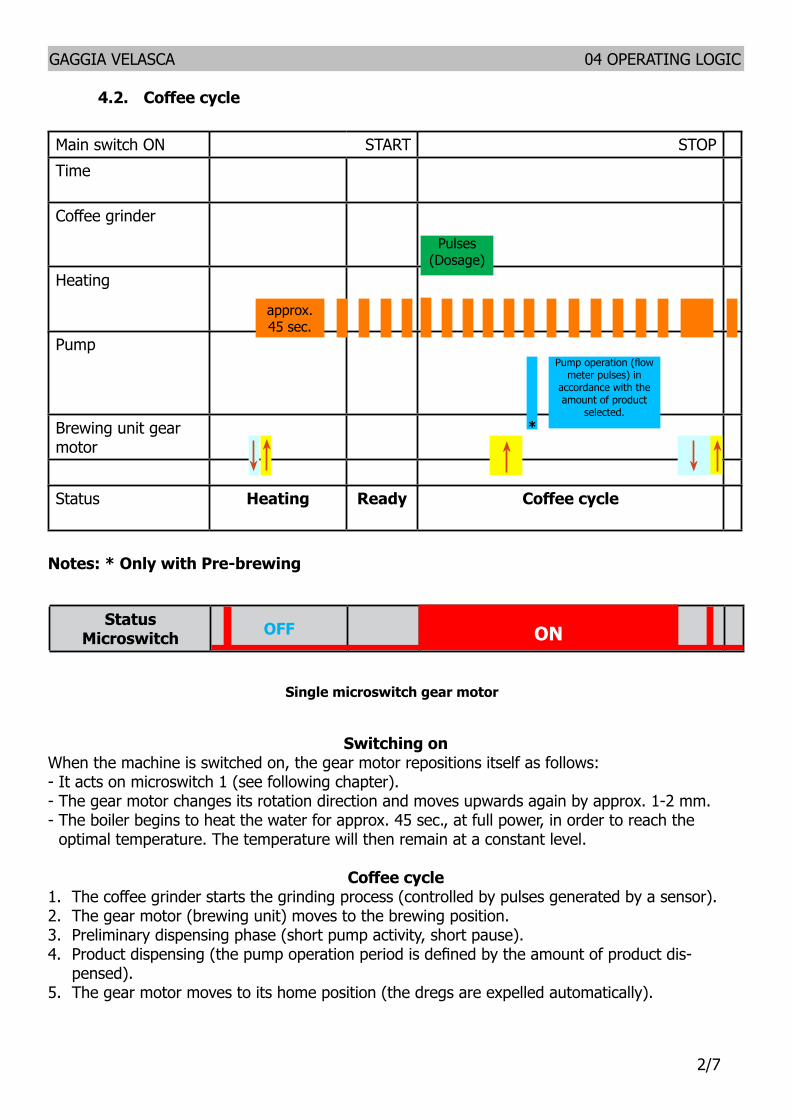
GAGGIA VELASCA 04 OPERATING LOGIC
27
42 Coffee cycle
Notes Only with Pre-brewing
Switching onWhen the machine is switched on the gear motor repositions itself as follows- It acts on microswitch 1 (see following chapter)- The gear motor changes its rotation direction and moves upwards again by approx 1-2 mm- The boiler begins to heat the water for approx 45 sec at full power in order to reach the
optimal temperature The temperature will then remain at a constant level
Coffee cycle1 The coffee grinder starts the grinding process (controlled by pulses generated by a sensor)2 The gear motor (brewing unit) moves to the brewing position3 Preliminary dispensing phase (short pump activity short pause)4 Product dispensing (the pump operation period is defined by the amount of product dis-
pensed)5 The gear motor moves to its home position (the dregs are expelled automatically)
Main switch ON START STOPTime
Coffee grinder
Heating
Pump
Brewing unit gear motor
Status Heating Ready Coffee cycle
Pulses (Dosage)
Pump operation (flow meter pulses) in
accordance with the amount of product
selected
approx 45 sec
Single microswitch gear motor
StatusMicroswitch OFF ON
GAGGIA VELASCA 04 OPERATING LOGIC
37
43 Single microswitch
Switching onWhen the machine is switched on the gear motor repositions itself as follows- It acts on microswitch 1 - The gear motor changes its rotation direction and moves upwards again by approx 1-2 mm- The boiler begins to heat the water for approx 45 sec at full power in order to reach the optimal
temperature The temperature will then remain at a constant level
An NTC is used as a temperature sensor in the event of overheating this reduces boiler element power consumptionThe electronic system detects the current boiler temperature from the drop in voltage of the sensor and adjusts it accordinglyHeating element values and corresponding temperatures see table
431 Temperature sensor (adjustment)
Temp (degC) R nom (kΩ) ΔR (+- )20 61465 8650 17599 5975 7214 4180 6121 3785 5213 3490 4459 31
100 33 25125 1653 39150 0893 51
The gear motor is powered by a direct current mo-tor that engages with the smaller double toothed wheel using a worm screw The unit is mounted on the axle of the large gear wheel and when a coffee is requested it moves from the standby position to the dispensing position and then back to the standby position again
- Standby position 1
- Dispensing position 2
2
1
GAGGIA VELASCA 04 OPERATING LOGIC
47
45 Autodose system description 230VmA
I0
I0 + 100
I0 + 55
I0 + 200Aroma 45
Aroma 23
Aroma 1
Auto-Zero
100le I0 le300
I0 = current when the BU is moving without load ie without coffee It occurs for example dur-ing the rinsing phase of coffee spout Current targets
Aroma 1 55mAAroma 23 100mAAroma 45 200mA100 mA le I0 le 300 mA
If the BU current is le the current target the grinding timeIf the BU current is ge the current target the grinding time
44 Coffee grinder 230V
The coffee grinder is driven by a direct current motor (1) using a worm screw helicoidal wheel transmission (2)The worm screw (2) drives a plastic gear wheel (3) which turns the lower grinder (4) and the increment pin (5)
23
4
5
1
GAGGIA VELASCA 04 OPERATING LOGIC
57
1) When the system get the stability (ie the system got the current target) the coffee doses should be A1 A23 A45
75 90 10 plusmn15 grams
with medium grinding (500plusmn60μm) and using coffee of test
2) the 3 grinding times are always
T1ltT2ltT3
beside every grinding time is respectively
40s leT3 le10s (10000ms)35s leT2 le9s (9000ms)30s leT1 le81s (8100ms)
DOSE ADJUSTMENT
5 levels Grinder Time
Min Grinder
Time
Max Grinder
TimeCurret target
Aroma of the
grinded product
Aroma1 Very Light T1 3s 81s I0 + 55mAAroma2 Light T2 35s 9s I0 + 100mAAroma3 Med
Aroma4 Strong T3 4s 10s I0 + 200mAAroma5 Very Strong
46 Coffee lack detection and coffee grinder blocked 230V
When the coffee grinder is working the software monitors the current consumption If the current value is very low the machine concludes that coffee is missing if the current value is very high the machine concludes that the coffee grinder is blocked instead if the current value is in the middle the machine concludes that all is ok and it goes on to do the productBecause the current consumption of grinder changes depending on the situations (motor new or old cold or hot etc coffee blends) these current thresholds are not static but dynamic
GAGGIA VELASCA 04 OPERATING LOGIC
67
47 Water level detection (water tank)
ldquoWater lowrdquo message (water reserve)
FunctionThe water level is monitored by a capacitative sensor located one third of the way up the water tank wallIf the electronics assembly detects by means of the sensor that the amount of water in the tank has dropped below the above mentioned level a water reserve remains available for the dispensing process underway (this will cover 200 flow meter pulses)The product dispensing process will then come to an endIf a dispensing cycle ends after the sensor has been triggered (in the reserve) then the display ldquoWater lowrdquo continues to be displayed during the following dispensing cycle
200 puls
Sensor
Water tank
48 Milk Carafe
1) Steam input2)Bring the cappuccino maker into dispensing
position 3) Milk tank
The steam passes through the pipe creating a sucking effect that pulls the milk upwards
Steam
The milk is heated by the steam and taken towards the emulsion chamber where it is mixed with air and transformed into foam
MINUTO 04 OPERATING LOGIC
Page 10
44 Milk Carafe
1) Steam input2)Bring the cappuccino maker into dispensing
position 3) Milk tank
1
2
3
04
The steam passes through the pipe creating a sucking effect that pulls the milk upwards
Steam
The milk is heated by the steam and taken towards the emulsion chamber where it is mixed with air and transformed into foam
GAGGIA VELASCA 04 OPERATING LOGIC
77
49 AquaClean water filter
The AquaClean filter is designed to reduce limescale deposits in the coffee machine and provide filtered water to preserve the aroma and flavor of each cup of coffee By using a series of 8 AquaClean filters there is no need to descale the machine for 5000 cups (It depends both on the type of coffee used rinsing and cleaning programs) We recommend installing the water filter AquaClean the first use of the machine to the maximum before using 5 L of water The machine display will indicate when the filter needs to be replaced The maximum limit is equivalent to 110 L of water The conditions related to the filter work environment (water therefore an active environment for bacteria and microorganisms) require the replacement with a minimum frequency (we suggest 3 months from the activation to ensure the best performance) The filter startsrsquo working from the time is filled with water and continues working even with the machine off It cannot be deactivated manually as it must end its life cycle At the filter activation the display shows the icon with the percentage of use
- Initially 100 then decreasingWhen the autonomy of the current filter becomes less than 8 L of water the display shows
- The icon flashing slowly It means 10 When the autonomy of the current filter becomes less than 2 L of water the display shows
- The icon flashing quickly It means 0 After a maximum of 110 L of water supplied the flashing light turn off and the machine needs to be descaled
GAGGIA VELASCA
CHAPTER 5 SERVICE MODE
GAGGIA VELASCA 05 SERVICE MODE
18
51 Test Mode
IntroductionThis document describes the manual Test Mode of the GAGGIA VELASCA coffee appliance
To enter Test Mode To activate the manual Test Mode the user must press at the same time the ldquoEspressordquo and ldquoMenurdquo (ldquoSpecial Drinksrdquo for OTC version) buttons while connecting the CA to the power supplyOnce entered the Test Mode the first page of seven is shownEntering page the display shows a) The name of the machine and the installed firmware version b) The supply voltage c) The AC supply net frequency detected by the CAPage 1 Keyboard and display colors testing 1) Espresso button 2) Coffee button 3) Steam button (Aroma button for OTC version) 4) Hot Water button (Cappuccino button for OTC version) 5) Aroma button (Milk Froth button for OTC version) 6) Menu button (Special Drinks button for OTC version) 7) Stand-by button 8) Clean button (only OTC version) 9) Menu button (only OTC version)Page 2 Input signals testing a) Water tank sensor b) Door closedopened microswitch c) Coffee Brewing Unit insertion microswitch d) Dreg Drawer insertion microswitchPage 3 Coffee Brewing Unit testing a) UpDown BU movement (24V DC) b) BU effort currentPage 4 Hydraulic circuit loads testing (Pump Electrovalve) a) pump (120-230V AC) b) 2 ways Electrovalve (24Vdc)Page 5 Heater and Grinder testing a) Heater (120-230V AC) b) Grinder (320V DC)Page 6 Autodose quantities a) Light b) Med c) Strong
Test Mode INTELIA EVO V2 AMF
Filename Intelia_EVO2_AMF_TestMode_V05
50 G Divella 12062015 312 revNum Author Verified Approved SaveDate PPP
When accessing the Test Mode all the loads are turned off
11 Entering Page
Used to verify firmware version and some built-in parameters
This page shows the firmware version installed the supply voltage (230V or 120V) and the AC net frequency (50Hz or 60 Hz)
Itrsquos always required to check if the firmware version shown on the display is the same printed on the microcontroller label
Warning If the two version do not match the PCB must be dismissed
Press STEAMThe CA goes to page 1 (KEYB)
Test Mode INTELIA EVO V2 AMF
Filename Intelia_EVO2_AMF_TestMode_V05
50 G Divella 12062015 312 revNum Author Verified Approved SaveDate PPP
When accessing the Test Mode all the loads are turned off
11 Entering Page
Used to verify firmware version and some built-in parameters
This page shows the firmware version installed the supply voltage (230V or 120V) and the AC net frequency (50Hz or 60 Hz)
Itrsquos always required to check if the firmware version shown on the display is the same printed on the microcontroller label
Warning If the two version do not match the PCB must be dismissed
Press STEAMThe CA goes to page 1 (KEYB)
Test Mode INTELIA EVO V2 AMF
Filename Intelia_EVO2_AMF_TestMode_V05
50 G Divella 12062015 312 revNum Author Verified Approved SaveDate PPP
When accessing the Test Mode all the loads are turned off
11 Entering Page
Used to verify firmware version and some built-in parameters
This page shows the firmware version installed the supply voltage (230V or 120V) and the AC net frequency (50Hz or 60 Hz)
Itrsquos always required to check if the firmware version shown on the display is the same printed on the microcontroller label
Warning If the two version do not match the PCB must be dismissed
Press STEAMThe CA goes to page 1 (KEYB)
Test Mode INTELIA EVO V2 AMF
Filename Intelia_EVO2_AMF_TestMode_V05
50 G Divella 12062015 412 revNum Author Verified Approved SaveDate PPP
12 Page 1 (KEYB) Initial condition no button pressed
Press all the buttons from Ndeg1 till Ndeg9Whenever a button is pressed the ldquoONrdquo word appears near the related button number Pressing button Ndeg1 the backlight color switches from WHITE to REDPressing button Ndeg2 the backlight color switches from WHITE to PINK Pressing button Ndeg7 turns the STANDBY LED on To test button Ndeg4 it must be pressed just one time because it causes the CA to navigate to the next page
In case two or more buttons are pressed at the same time the display shows the expression ldquoTWO BTNrdquo This could be a useful warning if the keyboard is not working properly
ERRORS occur if ldquoONrdquo word does not appear or stays fixed on screen In this case itrsquos necessary to check the communication flat cable connected between the keyboard and the CPU-Power board Should not on the other hand change the display color check the JP5 cable
Pressing STEAM button The CA switches to page 2 (INPUTS)
Test Mode INTELIA EVO V2 AMF
Filename Intelia_EVO2_AMF_TestMode_V05
50 G Divella 12062015 412 revNum Author Verified Approved SaveDate PPP
12 Page 1 (KEYB) Initial condition no button pressed
Press all the buttons from Ndeg1 till Ndeg9Whenever a button is pressed the ldquoONrdquo word appears near the related button number Pressing button Ndeg1 the backlight color switches from WHITE to REDPressing button Ndeg2 the backlight color switches from WHITE to PINK Pressing button Ndeg7 turns the STANDBY LED on To test button Ndeg4 it must be pressed just one time because it causes the CA to navigate to the next page
In case two or more buttons are pressed at the same time the display shows the expression ldquoTWO BTNrdquo This could be a useful warning if the keyboard is not working properly
ERRORS occur if ldquoONrdquo word does not appear or stays fixed on screen In this case itrsquos necessary to check the communication flat cable connected between the keyboard and the CPU-Power board Should not on the other hand change the display color check the JP5 cable
Pressing STEAM button The CA switches to page 2 (INPUTS)
Test Mode INTELIA EVO V2 AMF
Filename Intelia_EVO2_AMF_TestMode_V05
50 G Divella 12062015 412 revNum Author Verified Approved SaveDate PPP
12 Page 1 (KEYB) Initial condition no button pressed
Press all the buttons from Ndeg1 till Ndeg9Whenever a button is pressed the ldquoONrdquo word appears near the related button number Pressing button Ndeg1 the backlight color switches from WHITE to REDPressing button Ndeg2 the backlight color switches from WHITE to PINK Pressing button Ndeg7 turns the STANDBY LED on To test button Ndeg4 it must be pressed just one time because it causes the CA to navigate to the next page
In case two or more buttons are pressed at the same time the display shows the expression ldquoTWO BTNrdquo This could be a useful warning if the keyboard is not working properly
ERRORS occur if ldquoONrdquo word does not appear or stays fixed on screen In this case itrsquos necessary to check the communication flat cable connected between the keyboard and the CPU-Power board Should not on the other hand change the display color check the JP5 cable
Pressing STEAM button The CA switches to page 2 (INPUTS)
Test Mode INTELIA EVO V2 AMF
Filename Intelia_EVO2_AMF_TestMode_V05
50 G Divella 12062015 312 revNum Author Verified Approved SaveDate PPP
When accessing the Test Mode all the loads are turned off
11 Entering Page
Used to verify firmware version and some built-in parameters
This page shows the firmware version installed the supply voltage (230V or 120V) and the AC net frequency (50Hz or 60 Hz)
Itrsquos always required to check if the firmware version shown on the display is the same printed on the microcontroller label
Warning If the two version do not match the PCB must be dismissed
Press STEAMThe CA goes to page 1 (KEYB)
GAGGIA VELASCA 05 SERVICE MODE
28
11 Entering Page
12 Page 1 (KEYB)
Verify the firmware version
This page shows the firmware version installed the supply voltage (230V or 120V) and the AC net frequency (50Hz or 60 Hz)
Itrsquos always required to check if the firmware version shown on the display is the same printed on the microcontroller label
WarningIf the two version do not match the PCB must be dismissed
Press STEAM (Press CAPPUCCINO for OTC version)
The CA goes to page 1 (KEYB)
Initial condition no button pressed
Press all the buttons from Ndeg1 till Ndeg9Whenever a button is pressed the ldquoONrdquo word appears near the related button numberPressing button Ndeg1 the backlight color switches from WHITE to REDPressing button Ndeg2 the backlight color switches from WHITE to PINKPressing button Ndeg7 turns the STANDBY LED onTo test button Ndeg4 it must be pressed just one time because it causes the CA to navigate to the next page
In case two or more buttons are pressed at the same time the display shows the expression ldquoTWO BTNrdquo This could be a useful warning if the keyboard is not working properly
ERRORS occur ifldquoONrdquo word does not appear or stays fixed on screen In this case itrsquos necessary to check the communication flat cable connected between the keyboard and the CPU-Power board Should not on the other hand change the display color check the JP5 cable
Test Mode INTELIA EVO V2 AMF
Filename Intelia_EVO2_AMF_TestMode_V05
50 G Divella 12062015 412 revNum Author Verified Approved SaveDate PPP
12 Page 1 (KEYB) Initial condition no button pressed
Press all the buttons from Ndeg1 till Ndeg9Whenever a button is pressed the ldquoONrdquo word appears near the related button number Pressing button Ndeg1 the backlight color switches from WHITE to REDPressing button Ndeg2 the backlight color switches from WHITE to PINK Pressing button Ndeg7 turns the STANDBY LED on To test button Ndeg4 it must be pressed just one time because it causes the CA to navigate to the next page
In case two or more buttons are pressed at the same time the display shows the expression ldquoTWO BTNrdquo This could be a useful warning if the keyboard is not working properly
ERRORS occur if ldquoONrdquo word does not appear or stays fixed on screen In this case itrsquos necessary to check the communication flat cable connected between the keyboard and the CPU-Power board Should not on the other hand change the display color check the JP5 cable
Pressing STEAM button The CA switches to page 2 (INPUTS)
Test Mode INTELIA EVO V2 AMF Filename
Intelia_EVO2_AMF_TestMode_V05
50 G Divella 12062015 512 revNum Author Verified Approved SaveDate PPP
13 Page 2 (INPUTS) Initial condition (having removed all the components)
Insert the tank full of waterThe H2O value must turn from ldquoNrdquo to ldquoYrdquo
ERRORS occur if If the H2O value doesnrsquot change check the capacitive sensor and the related wiring (JP23)
Insert the Dreg DrawerThe DREG value must turn from ldquoNrdquo to ldquoYrdquo
ERRORS occur if If the DREG value doesnrsquot change check the dreg drawer microswitch and the related wiring (JP16)
Close the Side Door (having the dreg drawer already inserted) The DOOR value must turn from ldquoNrdquo to ldquoYrdquo
ERRORS occur if If the DOOR value doesnrsquot change check the side door microswitch and the related wiring (JP14) and verify that the dreg drawer is correctly inserted
Test Mode INTELIA EVO V2 AMF Filename
Intelia_EVO2_AMF_TestMode_V05
50 G Divella 12062015 512 revNum Author Verified Approved SaveDate PPP
13 Page 2 (INPUTS) Initial condition (having removed all the components)
Insert the tank full of waterThe H2O value must turn from ldquoNrdquo to ldquoYrdquo
ERRORS occur if If the H2O value doesnrsquot change check the capacitive sensor and the related wiring (JP23)
Insert the Dreg DrawerThe DREG value must turn from ldquoNrdquo to ldquoYrdquo
ERRORS occur if If the DREG value doesnrsquot change check the dreg drawer microswitch and the related wiring (JP16)
Close the Side Door (having the dreg drawer already inserted) The DOOR value must turn from ldquoNrdquo to ldquoYrdquo
ERRORS occur if If the DOOR value doesnrsquot change check the side door microswitch and the related wiring (JP14) and verify that the dreg drawer is correctly inserted
Test Mode INTELIA EVO V2 AMF Filename
Intelia_EVO2_AMF_TestMode_V05
50 G Divella 12062015 512 revNum Author Verified Approved SaveDate PPP
13 Page 2 (INPUTS) Initial condition (having removed all the components)
Insert the tank full of waterThe H2O value must turn from ldquoNrdquo to ldquoYrdquo
ERRORS occur if If the H2O value doesnrsquot change check the capacitive sensor and the related wiring (JP23)
Insert the Dreg DrawerThe DREG value must turn from ldquoNrdquo to ldquoYrdquo
ERRORS occur if If the DREG value doesnrsquot change check the dreg drawer microswitch and the related wiring (JP16)
Close the Side Door (having the dreg drawer already inserted) The DOOR value must turn from ldquoNrdquo to ldquoYrdquo
ERRORS occur if If the DOOR value doesnrsquot change check the side door microswitch and the related wiring (JP14) and verify that the dreg drawer is correctly inserted Test Mode INTELIA EVO V2 AMF
Filename Intelia_EVO2_AMF_TestMode_V05
50 G Divella 12062015 612 revNum Author Verified Approved SaveDate PPP
Insert the Brewing Unit The BU-P value must turn from ldquoNrdquo to ldquoYrdquo
ERRORS occur if If the BU-P value doesnrsquot change check the BU presence microswitch and the related wiring (JP16)
Test Mode INTELIA EVO V2 AMF
Filename Intelia_EVO2_AMF_TestMode_V05
50 G Divella 12062015 412 revNum Author Verified Approved SaveDate PPP
12 Page 1 (KEYB) Initial condition no button pressed
Press all the buttons from Ndeg1 till Ndeg9Whenever a button is pressed the ldquoONrdquo word appears near the related button number Pressing button Ndeg1 the backlight color switches from WHITE to REDPressing button Ndeg2 the backlight color switches from WHITE to PINK Pressing button Ndeg7 turns the STANDBY LED on To test button Ndeg4 it must be pressed just one time because it causes the CA to navigate to the next page
In case two or more buttons are pressed at the same time the display shows the expression ldquoTWO BTNrdquo This could be a useful warning if the keyboard is not working properly
ERRORS occur if ldquoONrdquo word does not appear or stays fixed on screen In this case itrsquos necessary to check the communication flat cable connected between the keyboard and the CPU-Power board Should not on the other hand change the display color check the JP5 cable
Pressing STEAM button The CA switches to page 2 (INPUTS)
GAGGIA VELASCA 05 SERVICE MODE
38
13 Page 2 (INPUTS)
Insert the tank full of water
The H2O value must turn from ldquoNrdquo to ldquoYrdquo
ERRORS occur ifIf the H2O value doesnrsquot change check the capacitive sensor and the re-lated wiring (JP23)
Insert the Dreg Drawer
The DREG value must turn from ldquoNrdquo to ldquoYrdquo
ERRORS occur ifIf the DREG value doesnrsquot change check the dreg drawer microswitch and the related wiring (JP16)
Close the Side Door (having the dreg drawer already inserted)
The DOOR value must turn from ldquoNrdquo to ldquoYrdquo
ERRORS occur ifIf the DOOR value doesnrsquot change check the side door microswitch and the related wiring (JP14) and verify that the dreg drawer is correctly in-serted
Insert the Brewing Unit
The BU-P value must turn from ldquoNrdquo to ldquoYrdquo
ERRORS occur ifIf the BU-P value doesnrsquot change check the BU presence microswitch and the related wiring (JP16)
Initial condition (having removed all the components)
The CA switches to page 2 (INPUTS)
Pressing STEAM button (Press CAPPUCCINO for OTC version)
Test Mode INTELIA EVO V2 AMF Filename
Intelia_EVO2_AMF_TestMode_V05
50 G Divella 12062015 712 revNum Author Verified Approved SaveDate PPP
14 Page 3 (BU)
Initial condition
Press the ESPRESSO button to conduct the BU to the Work position When the BU reaches the work position the value WORK turns from ldquoNrdquo to ldquoYrdquo The absorbed BU current must be less than 200mA if the BU is not inserted and less than 300mA if the BU is inserted
ERRORS occur if The WORK value stays fixed on ldquoNrdquo while the backlight turns RED from WHITE in this case check the microswitch the BU engine (could be blocked) and finally the JP16 and JP14 wirings
ERROR (BU not inserted) If the absorbed current is more than 200 mA the display backlight turns red In this case check the gears of the engine and its standing in the housing
ERROR (BU inserted)If the absorbed current is more than 300 mA the display backlight turns red In this case check the gears of the engine and its standing in the housing
Test Mode INTELIA EVO V2 AMF Filename
Intelia_EVO2_AMF_TestMode_V05
50 G Divella 12062015 712 revNum Author Verified Approved SaveDate PPP
14 Page 3 (BU)
Initial condition
Press the ESPRESSO button to conduct the BU to the Work position When the BU reaches the work position the value WORK turns from ldquoNrdquo to ldquoYrdquo The absorbed BU current must be less than 200mA if the BU is not inserted and less than 300mA if the BU is inserted
ERRORS occur if The WORK value stays fixed on ldquoNrdquo while the backlight turns RED from WHITE in this case check the microswitch the BU engine (could be blocked) and finally the JP16 and JP14 wirings
ERROR (BU not inserted) If the absorbed current is more than 200 mA the display backlight turns red In this case check the gears of the engine and its standing in the housing
ERROR (BU inserted)If the absorbed current is more than 300 mA the display backlight turns red In this case check the gears of the engine and its standing in the housing
Test Mode INTELIA EVO V2 AMF Filename
Intelia_EVO2_AMF_TestMode_V05
50 G Divella 12062015 712 revNum Author Verified Approved SaveDate PPP
14 Page 3 (BU)
Initial condition
Press the ESPRESSO button to conduct the BU to the Work position When the BU reaches the work position the value WORK turns from ldquoNrdquo to ldquoYrdquo The absorbed BU current must be less than 200mA if the BU is not inserted and less than 300mA if the BU is inserted
ERRORS occur if The WORK value stays fixed on ldquoNrdquo while the backlight turns RED from WHITE in this case check the microswitch the BU engine (could be blocked) and finally the JP16 and JP14 wirings
ERROR (BU not inserted) If the absorbed current is more than 200 mA the display backlight turns red In this case check the gears of the engine and its standing in the housing
ERROR (BU inserted)If the absorbed current is more than 300 mA the display backlight turns red In this case check the gears of the engine and its standing in the housing
Test Mode INTELIA EVO V2 AMF Filename
Intelia_EVO2_AMF_TestMode_V05
50 G Divella 12062015 712 revNum Author Verified Approved SaveDate PPP
14 Page 3 (BU)
Initial condition
Press the ESPRESSO button to conduct the BU to the Work position When the BU reaches the work position the value WORK turns from ldquoNrdquo to ldquoYrdquo The absorbed BU current must be less than 200mA if the BU is not inserted and less than 300mA if the BU is inserted
ERRORS occur if The WORK value stays fixed on ldquoNrdquo while the backlight turns RED from WHITE in this case check the microswitch the BU engine (could be blocked) and finally the JP16 and JP14 wirings
ERROR (BU not inserted) If the absorbed current is more than 200 mA the display backlight turns red In this case check the gears of the engine and its standing in the housing
ERROR (BU inserted)If the absorbed current is more than 300 mA the display backlight turns red In this case check the gears of the engine and its standing in the housing
Test Mode INTELIA EVO V2 AMF Filename
Intelia_EVO2_AMF_TestMode_V05
50 G Divella 12062015 712 revNum Author Verified Approved SaveDate PPP
14 Page 3 (BU)
Initial condition
Press the ESPRESSO button to conduct the BU to the Work position When the BU reaches the work position the value WORK turns from ldquoNrdquo to ldquoYrdquo The absorbed BU current must be less than 200mA if the BU is not inserted and less than 300mA if the BU is inserted
ERRORS occur if The WORK value stays fixed on ldquoNrdquo while the backlight turns RED from WHITE in this case check the microswitch the BU engine (could be blocked) and finally the JP16 and JP14 wirings
ERROR (BU not inserted) If the absorbed current is more than 200 mA the display backlight turns red In this case check the gears of the engine and its standing in the housing
ERROR (BU inserted)If the absorbed current is more than 300 mA the display backlight turns red In this case check the gears of the engine and its standing in the housing
Test Mode INTELIA EVO V2 AMF Filename
Intelia_EVO2_AMF_TestMode_V05
50 G Divella 12062015 812 revNum Author Verified Approved SaveDate PPP
Press the COFFEE button to move the BU towards the HOME position When the BU reaches the HOME position the HOME value changes from ldquoNrdquo to ldquoYrdquo The maximum absorbed current must be less than 200 mA (BU not inserted) 300 mA (BU inserted)
ERRORS occur if The HOME value stays fixed on ldquoNrdquo while the backlight turns RED from WHITE in this case check the microswitch the BU engine (could be blocked) and finally the JP16 and JP14 wirings
ERROR (BU not inserted) If the absorbed current is more than 200 mA the display backlight turns red In this case check the gears of the engine and its standing in the housing
ERROR (BU inserted)If the absorbed current is more than 300 mA the display backlight turns red In this case check the gears of the engine and its standing in the housing
Press the STEAM button The CA goes to the EVPUMP page (EV - PUMP)
Test Mode INTELIA EVO V2 AMF Filename
Intelia_EVO2_AMF_TestMode_V05
50 G Divella 12062015 812 revNum Author Verified Approved SaveDate PPP
Press the COFFEE button to move the BU towards the HOME position When the BU reaches the HOME position the HOME value changes from ldquoNrdquo to ldquoYrdquo The maximum absorbed current must be less than 200 mA (BU not inserted) 300 mA (BU inserted)
ERRORS occur if The HOME value stays fixed on ldquoNrdquo while the backlight turns RED from WHITE in this case check the microswitch the BU engine (could be blocked) and finally the JP16 and JP14 wirings
ERROR (BU not inserted) If the absorbed current is more than 200 mA the display backlight turns red In this case check the gears of the engine and its standing in the housing
ERROR (BU inserted)If the absorbed current is more than 300 mA the display backlight turns red In this case check the gears of the engine and its standing in the housing
Press the STEAM button The CA goes to the EVPUMP page (EV - PUMP)
Test Mode INTELIA EVO V2 AMF Filename
Intelia_EVO2_AMF_TestMode_V05
50 G Divella 12062015 812 revNum Author Verified Approved SaveDate PPP
Press the COFFEE button to move the BU towards the HOME position When the BU reaches the HOME position the HOME value changes from ldquoNrdquo to ldquoYrdquo The maximum absorbed current must be less than 200 mA (BU not inserted) 300 mA (BU inserted)
ERRORS occur if The HOME value stays fixed on ldquoNrdquo while the backlight turns RED from WHITE in this case check the microswitch the BU engine (could be blocked) and finally the JP16 and JP14 wirings
ERROR (BU not inserted) If the absorbed current is more than 200 mA the display backlight turns red In this case check the gears of the engine and its standing in the housing
ERROR (BU inserted)If the absorbed current is more than 300 mA the display backlight turns red In this case check the gears of the engine and its standing in the housing
Press the STEAM button The CA goes to the EVPUMP page (EV - PUMP)
Test Mode INTELIA EVO V2 AMF Filename
Intelia_EVO2_AMF_TestMode_V05
50 G Divella 12062015 812 revNum Author Verified Approved SaveDate PPP
Press the COFFEE button to move the BU towards the HOME position When the BU reaches the HOME position the HOME value changes from ldquoNrdquo to ldquoYrdquo The maximum absorbed current must be less than 200 mA (BU not inserted) 300 mA (BU inserted)
ERRORS occur if The HOME value stays fixed on ldquoNrdquo while the backlight turns RED from WHITE in this case check the microswitch the BU engine (could be blocked) and finally the JP16 and JP14 wirings
ERROR (BU not inserted) If the absorbed current is more than 200 mA the display backlight turns red In this case check the gears of the engine and its standing in the housing
ERROR (BU inserted)If the absorbed current is more than 300 mA the display backlight turns red In this case check the gears of the engine and its standing in the housing
Press the STEAM button The CA goes to the EVPUMP page (EV - PUMP)
Test Mode INTELIA EVO V2 AMF Filename
Intelia_EVO2_AMF_TestMode_V05
50 G Divella 12062015 812 revNum Author Verified Approved SaveDate PPP
Press the COFFEE button to move the BU towards the HOME position When the BU reaches the HOME position the HOME value changes from ldquoNrdquo to ldquoYrdquo The maximum absorbed current must be less than 200 mA (BU not inserted) 300 mA (BU inserted)
ERRORS occur if The HOME value stays fixed on ldquoNrdquo while the backlight turns RED from WHITE in this case check the microswitch the BU engine (could be blocked) and finally the JP16 and JP14 wirings
ERROR (BU not inserted) If the absorbed current is more than 200 mA the display backlight turns red In this case check the gears of the engine and its standing in the housing
ERROR (BU inserted)If the absorbed current is more than 300 mA the display backlight turns red In this case check the gears of the engine and its standing in the housing
Press the STEAM button The CA goes to the EVPUMP page (EV - PUMP)
GAGGIA VELASCA 05 SERVICE MODE
48
14 Page 3 (BU)
Press the ESPRESSO button to conduct the BU to the Work position
When the BU reaches the work position the value WORK turns from ldquoNrdquo to ldquoYrdquo The absorbed BU current must be less than 200mA if the BU is not inserted and less than 300mA if the BU is inserted
ERRORS occur ifThe WORK value stays fixed on ldquoNrdquo while the backlight turns RED from WHITE in this case check the microswitch the BU engine (could be blocked) and finally the JP16 and JP14 wiringsERROR (BU not inserted)If the absorbed current is more than 200 mA the display backlight turns red In this case check the gears of the engine and its standing in the housingERROR (BU inserted)If the absorbed current is more than 300 mA the display backlight turns red In this case check the gears of the engine and its standing in the housing
Press the COFFEE button to move the BU towards the HOME position
When the BU reaches the HOME position the HOME value changes from ldquoNrdquo to ldquoYrdquo The maximum absorbed current must be less than 200 mA (BU not inserted) 300 mA (BU inserted)
ERRORS occur ifThe HOME value stays fixed on ldquoNrdquo while the backlight turns RED from WHITE in this case check the microswitch the BU engine (could be blocked) and finally the JP16 and JP14 wiringsERROR (BU not inserted)If the absorbed current is more than 200 mA the display backlight turns red In this case check the gears of the engine and its standing in the housingERROR (BU inserted)If the absorbed current is more than 300 mA the display backlight turns red In this case check the gears of the engine and its standing in the housing
Press the STEAM button (Press CAPPUCCINO for OTC version)
The CA goes to the EVPUMP page (EV - PUMP)
Initial condition
Test Mode INTELIA EVO V2 AMF Filename
Intelia_EVO2_AMF_TestMode_V05
50 G Divella 12062015 912 revNum Author Verified Approved SaveDate PPP
15 Page 4 (EV - PUMP)
Should this page been shown it means either the dreg drawer is not correctly inserted or the side door not closed Only solving both these issues it would be possible to come out from this screen
Press the ESPRESSO button to activate the 2-ways Electrovalve (closed by default) The Electrovalve is activated so the EV1 value turns from ldquoOFFrdquo to ldquoONrdquo
Press the HOT WATER button to activate the PumpThe water now flows out from the spout causing the update of the IMP value with the number of flowmeter impulses The LH value must stay within 10lh and 18 lh
ERROR If the number of impulses remains 0 and the display backlight turns red it means that therersquos an error in the hydraulic circuit If water comes out from the spout it means that therersquos an error in the flowmeter or in its wiring to the CPUPOWER (JP5) if on the other hand no water comes out itrsquos necessary to check the pump or the hydraulic circuit or the pump wiring (JP24)
Press the STEAM WATER button The CA shows the HeaterGrinder page (Heater-Grinder)
16 Page5 (Heater-Grinder)
Test Mode INTELIA EVO V2 AMF Filename
Intelia_EVO2_AMF_TestMode_V05
50 G Divella 12062015 912 revNum Author Verified Approved SaveDate PPP
15 Page 4 (EV - PUMP)
Should this page been shown it means either the dreg drawer is not correctly inserted or the side door not closed Only solving both these issues it would be possible to come out from this screen
Press the ESPRESSO button to activate the 2-ways Electrovalve (closed by default) The Electrovalve is activated so the EV1 value turns from ldquoOFFrdquo to ldquoONrdquo
Press the HOT WATER button to activate the PumpThe water now flows out from the spout causing the update of the IMP value with the number of flowmeter impulses The LH value must stay within 10lh and 18 lh
ERROR If the number of impulses remains 0 and the display backlight turns red it means that therersquos an error in the hydraulic circuit If water comes out from the spout it means that therersquos an error in the flowmeter or in its wiring to the CPUPOWER (JP5) if on the other hand no water comes out itrsquos necessary to check the pump or the hydraulic circuit or the pump wiring (JP24)
Press the STEAM WATER button The CA shows the HeaterGrinder page (Heater-Grinder)
16 Page5 (Heater-Grinder)
Test Mode INTELIA EVO V2 AMF Filename
Intelia_EVO2_AMF_TestMode_V05
50 G Divella 12062015 912 revNum Author Verified Approved SaveDate PPP
15 Page 4 (EV - PUMP)
Should this page been shown it means either the dreg drawer is not correctly inserted or the side door not closed Only solving both these issues it would be possible to come out from this screen
Press the ESPRESSO button to activate the 2-ways Electrovalve (closed by default) The Electrovalve is activated so the EV1 value turns from ldquoOFFrdquo to ldquoONrdquo
Press the HOT WATER button to activate the PumpThe water now flows out from the spout causing the update of the IMP value with the number of flowmeter impulses The LH value must stay within 10lh and 18 lh
ERROR If the number of impulses remains 0 and the display backlight turns red it means that therersquos an error in the hydraulic circuit If water comes out from the spout it means that therersquos an error in the flowmeter or in its wiring to the CPUPOWER (JP5) if on the other hand no water comes out itrsquos necessary to check the pump or the hydraulic circuit or the pump wiring (JP24)
Press the STEAM WATER button The CA shows the HeaterGrinder page (Heater-Grinder)
16 Page5 (Heater-Grinder)
Test Mode INTELIA EVO V2 AMF Filename
Intelia_EVO2_AMF_TestMode_V05
50 G Divella 12062015 912 revNum Author Verified Approved SaveDate PPP
15 Page 4 (EV - PUMP)
Should this page been shown it means either the dreg drawer is not correctly inserted or the side door not closed Only solving both these issues it would be possible to come out from this screen
Press the ESPRESSO button to activate the 2-ways Electrovalve (closed by default) The Electrovalve is activated so the EV1 value turns from ldquoOFFrdquo to ldquoONrdquo
Press the HOT WATER button to activate the PumpThe water now flows out from the spout causing the update of the IMP value with the number of flowmeter impulses The LH value must stay within 10lh and 18 lh
ERROR If the number of impulses remains 0 and the display backlight turns red it means that therersquos an error in the hydraulic circuit If water comes out from the spout it means that therersquos an error in the flowmeter or in its wiring to the CPUPOWER (JP5) if on the other hand no water comes out itrsquos necessary to check the pump or the hydraulic circuit or the pump wiring (JP24)
Press the STEAM WATER button The CA shows the HeaterGrinder page (Heater-Grinder)
16 Page5 (Heater-Grinder)
Test Mode INTELIA EVO V2 AMF Filename
Intelia_EVO2_AMF_TestMode_V05
50 G Divella 12062015 912 revNum Author Verified Approved SaveDate PPP
15 Page 4 (EV - PUMP)
Should this page been shown it means either the dreg drawer is not correctly inserted or the side door not closed Only solving both these issues it would be possible to come out from this screen
Press the ESPRESSO button to activate the 2-ways Electrovalve (closed by default) The Electrovalve is activated so the EV1 value turns from ldquoOFFrdquo to ldquoONrdquo
Press the HOT WATER button to activate the PumpThe water now flows out from the spout causing the update of the IMP value with the number of flowmeter impulses The LH value must stay within 10lh and 18 lh
ERROR If the number of impulses remains 0 and the display backlight turns red it means that therersquos an error in the hydraulic circuit If water comes out from the spout it means that therersquos an error in the flowmeter or in its wiring to the CPUPOWER (JP5) if on the other hand no water comes out itrsquos necessary to check the pump or the hydraulic circuit or the pump wiring (JP24)
Press the STEAM WATER button The CA shows the HeaterGrinder page (Heater-Grinder)
16 Page5 (Heater-Grinder)
Test Mode INTELIA EVO V2 AMF Filename
Intelia_EVO2_AMF_TestMode_V05
50 G Divella 12062015 912 revNum Author Verified Approved SaveDate PPP
15 Page 4 (EV - PUMP)
Should this page been shown it means either the dreg drawer is not correctly inserted or the side door not closed Only solving both these issues it would be possible to come out from this screen
Press the ESPRESSO button to activate the 2-ways Electrovalve (closed by default) The Electrovalve is activated so the EV1 value turns from ldquoOFFrdquo to ldquoONrdquo
Press the HOT WATER button to activate the PumpThe water now flows out from the spout causing the update of the IMP value with the number of flowmeter impulses The LH value must stay within 10lh and 18 lh
ERROR If the number of impulses remains 0 and the display backlight turns red it means that therersquos an error in the hydraulic circuit If water comes out from the spout it means that therersquos an error in the flowmeter or in its wiring to the CPUPOWER (JP5) if on the other hand no water comes out itrsquos necessary to check the pump or the hydraulic circuit or the pump wiring (JP24)
Press the STEAM WATER button The CA shows the HeaterGrinder page (Heater-Grinder)
16 Page5 (Heater-Grinder)
Test Mode INTELIA EVO V2 AMF Filename
Intelia_EVO2_AMF_TestMode_V05
50 G Divella 12062015 1012 revNum Author Verified Approved SaveDate PPP
Initial condition
Press the HOT WATER button to activate the GrinderThe coffee grinder starts milling for 5000 ms if the user doesnrsquot release the button before In this case the activation time is shown in the red-circled field of the picture
ERROR If this number keeps fixed at 0 the display turns red and the engine moves then there must be a fault in the grinder wiring (JP8) or in the grinder itself
Keep pressed STANDBY for 5 secs to reset grinder parameters Pressing button STANDBY for 5 secs resets grinder parameters
Test Mode INTELIA EVO V2 AMF Filename
Intelia_EVO2_AMF_TestMode_V05
50 G Divella 12062015 1012 revNum Author Verified Approved SaveDate PPP
Initial condition
Press the HOT WATER button to activate the GrinderThe coffee grinder starts milling for 5000 ms if the user doesnrsquot release the button before In this case the activation time is shown in the red-circled field of the picture
ERROR If this number keeps fixed at 0 the display turns red and the engine moves then there must be a fault in the grinder wiring (JP8) or in the grinder itself
Keep pressed STANDBY for 5 secs to reset grinder parameters Pressing button STANDBY for 5 secs resets grinder parameters
Test Mode INTELIA EVO V2 AMF Filename
Intelia_EVO2_AMF_TestMode_V05
50 G Divella 12062015 1012 revNum Author Verified Approved SaveDate PPP
Initial condition
Press the HOT WATER button to activate the GrinderThe coffee grinder starts milling for 5000 ms if the user doesnrsquot release the button before In this case the activation time is shown in the red-circled field of the picture
ERROR If this number keeps fixed at 0 the display turns red and the engine moves then there must be a fault in the grinder wiring (JP8) or in the grinder itself
Keep pressed STANDBY for 5 secs to reset grinder parameters Pressing button STANDBY for 5 secs resets grinder parameters
GAGGIA VELASCA 05 SERVICE MODE
58
15 Page 4 (EV - PUMP)
Press the ESPRESSO button to activate the 2-ways Electrovalve (closed by default)
The Electrovalve is activated so the EV1 value turns from ldquoOFFrdquo to ldquoONrdquo
Press the HOT WATER (Press MILK for OTC version) button to activate the Pump
The water now flows out from the spout causing the update of the IMP value with the number of flowmeter impulses The LH value must stay within 10lh and 18 lh
ERRORIf the number of impulses remains 0 and the display backlight turns red it means that therersquos an error in the hydraulic circuit If water comes out from the spout it means that therersquos an error in the flowmeter or in its wiring to the CPUPOWER (JP5) if on the other hand no water comes out itrsquos necessary to check the pump or the hydraulic circuit or the pump wiring (JP24)
Press the STEAM WATER button (Press CAPPUCCINO for OTC version)
The CA shows the HeaterGrinder page (Heater-Grinder)
Initial condition
Press the HOT WATER (Press MILK for OTC version) button to activate the Grinder
The coffee grinder starts milling for 5000 ms In this case the activation time is shown in the red-circled field of the picture
ERRORIf this number keeps fixed at 0or the grinder does not run the display turns red this means there must be a fault in the grinder wiring (JP8) or in the grinder itself or in the electronic board
Keep pressed STANDBY for 5 secs to reset grinder parameters
Pressing button STANDBY for 5 secs resets grinder parametersThis action is needed if the grinder has been replaced
Should this page been shown it means either the dreg drawer is not cor-rectly inserted or the side door not closed Only solving both these issues it would be possible to come out from this screen
16 Page 5 (Heater-Grinder)
Test Mode INTELIA EVO V2 AMF Filename
Intelia_EVO2_AMF_TestMode_V05
50 G Divella 12062015 1112 revNum Author Verified Approved SaveDate PPP
Heater Temperature monitoring The red-circled number shows the heater temperature in Celsius degrees
ERROR If inside the HEATER column appears the word ldquoSHORTrdquo then the NTC sensor is in a short-circuit state The display backlight turns RED from WHITE in this case the NTC wiring or the input CPUPOWER (JP13) must be checked
ERROR If inside the HEATER column appears the word ldquoOPENrdquo then the NTC sensor is disconnected The display backlight turns RED from WHITE In this case the connectivity of the NTC wiring to the CPUPOWER (JP13) must be checked
Press the COFFEE button to activate the heaterThe label switches from ldquoOFFrdquo to ldquoONrdquo and the number indicating the temperature starts to increase (and so the current absorbed by the CA on the power supply ndash ca 8 A 230V) For safety reasons it is possible to activate the heater keeping pressed the button for a maximum time of 5 seconds
Therersquos a further check on the temperature level should it rise over 120degC the display backlight turns pink and an alarm message appears In this scenario the heater is forced to stay turned off to avoid dangerous over-temperatures
ERROR If therersquos no temperature increasing the user must check the heater resistance its wiring to the CPUPOWER (JP19) and also the NTC wiring (JP13)
Press both the AROMA and the MENU buttons These values appear on the display
Grinding time applied during last mill Average of the low state duration of the current sensor
signal Threshold for the presenceabsence coffee detection
Test Mode INTELIA EVO V2 AMF Filename
Intelia_EVO2_AMF_TestMode_V05
50 G Divella 12062015 1112 revNum Author Verified Approved SaveDate PPP
Heater Temperature monitoring The red-circled number shows the heater temperature in Celsius degrees
ERROR If inside the HEATER column appears the word ldquoSHORTrdquo then the NTC sensor is in a short-circuit state The display backlight turns RED from WHITE in this case the NTC wiring or the input CPUPOWER (JP13) must be checked
ERROR If inside the HEATER column appears the word ldquoOPENrdquo then the NTC sensor is disconnected The display backlight turns RED from WHITE In this case the connectivity of the NTC wiring to the CPUPOWER (JP13) must be checked
Press the COFFEE button to activate the heaterThe label switches from ldquoOFFrdquo to ldquoONrdquo and the number indicating the temperature starts to increase (and so the current absorbed by the CA on the power supply ndash ca 8 A 230V) For safety reasons it is possible to activate the heater keeping pressed the button for a maximum time of 5 seconds
Therersquos a further check on the temperature level should it rise over 120degC the display backlight turns pink and an alarm message appears In this scenario the heater is forced to stay turned off to avoid dangerous over-temperatures
ERROR If therersquos no temperature increasing the user must check the heater resistance its wiring to the CPUPOWER (JP19) and also the NTC wiring (JP13)
Press both the AROMA and the MENU buttons These values appear on the display
Grinding time applied during last mill Average of the low state duration of the current sensor
signal Threshold for the presenceabsence coffee detection
Test Mode INTELIA EVO V2 AMF Filename
Intelia_EVO2_AMF_TestMode_V05
50 G Divella 12062015 1112 revNum Author Verified Approved SaveDate PPP
Heater Temperature monitoring The red-circled number shows the heater temperature in Celsius degrees
ERROR If inside the HEATER column appears the word ldquoSHORTrdquo then the NTC sensor is in a short-circuit state The display backlight turns RED from WHITE in this case the NTC wiring or the input CPUPOWER (JP13) must be checked
ERROR If inside the HEATER column appears the word ldquoOPENrdquo then the NTC sensor is disconnected The display backlight turns RED from WHITE In this case the connectivity of the NTC wiring to the CPUPOWER (JP13) must be checked
Press the COFFEE button to activate the heaterThe label switches from ldquoOFFrdquo to ldquoONrdquo and the number indicating the temperature starts to increase (and so the current absorbed by the CA on the power supply ndash ca 8 A 230V) For safety reasons it is possible to activate the heater keeping pressed the button for a maximum time of 5 seconds
Therersquos a further check on the temperature level should it rise over 120degC the display backlight turns pink and an alarm message appears In this scenario the heater is forced to stay turned off to avoid dangerous over-temperatures
ERROR If therersquos no temperature increasing the user must check the heater resistance its wiring to the CPUPOWER (JP19) and also the NTC wiring (JP13)
Press both the AROMA and the MENU buttons These values appear on the display
Grinding time applied during last mill Average of the low state duration of the current sensor
signal Threshold for the presenceabsence coffee detection
Test Mode INTELIA EVO V2 AMF Filename
Intelia_EVO2_AMF_TestMode_V05
50 G Divella 12062015 1112 revNum Author Verified Approved SaveDate PPP
Heater Temperature monitoring The red-circled number shows the heater temperature in Celsius degrees
ERROR If inside the HEATER column appears the word ldquoSHORTrdquo then the NTC sensor is in a short-circuit state The display backlight turns RED from WHITE in this case the NTC wiring or the input CPUPOWER (JP13) must be checked
ERROR If inside the HEATER column appears the word ldquoOPENrdquo then the NTC sensor is disconnected The display backlight turns RED from WHITE In this case the connectivity of the NTC wiring to the CPUPOWER (JP13) must be checked
Press the COFFEE button to activate the heaterThe label switches from ldquoOFFrdquo to ldquoONrdquo and the number indicating the temperature starts to increase (and so the current absorbed by the CA on the power supply ndash ca 8 A 230V) For safety reasons it is possible to activate the heater keeping pressed the button for a maximum time of 5 seconds
Therersquos a further check on the temperature level should it rise over 120degC the display backlight turns pink and an alarm message appears In this scenario the heater is forced to stay turned off to avoid dangerous over-temperatures
ERROR If therersquos no temperature increasing the user must check the heater resistance its wiring to the CPUPOWER (JP19) and also the NTC wiring (JP13)
Press both the AROMA and the MENU buttons These values appear on the display
Grinding time applied during last mill Average of the low state duration of the current sensor
signal Threshold for the presenceabsence coffee detection
Test Mode INTELIA EVO V2 AMF Filename
Intelia_EVO2_AMF_TestMode_V05
50 G Divella 12062015 1112 revNum Author Verified Approved SaveDate PPP
Heater Temperature monitoring The red-circled number shows the heater temperature in Celsius degrees
ERROR If inside the HEATER column appears the word ldquoSHORTrdquo then the NTC sensor is in a short-circuit state The display backlight turns RED from WHITE in this case the NTC wiring or the input CPUPOWER (JP13) must be checked
ERROR If inside the HEATER column appears the word ldquoOPENrdquo then the NTC sensor is disconnected The display backlight turns RED from WHITE In this case the connectivity of the NTC wiring to the CPUPOWER (JP13) must be checked
Press the COFFEE button to activate the heaterThe label switches from ldquoOFFrdquo to ldquoONrdquo and the number indicating the temperature starts to increase (and so the current absorbed by the CA on the power supply ndash ca 8 A 230V) For safety reasons it is possible to activate the heater keeping pressed the button for a maximum time of 5 seconds
Therersquos a further check on the temperature level should it rise over 120degC the display backlight turns pink and an alarm message appears In this scenario the heater is forced to stay turned off to avoid dangerous over-temperatures
ERROR If therersquos no temperature increasing the user must check the heater resistance its wiring to the CPUPOWER (JP19) and also the NTC wiring (JP13)
Press both the AROMA and the MENU buttons These values appear on the display
Grinding time applied during last mill Average of the low state duration of the current sensor
signal Threshold for the presenceabsence coffee detection
Test Mode INTELIA EVO V2 AMF Filename
Intelia_EVO2_AMF_TestMode_V05
50 G Divella 12062015 1112 revNum Author Verified Approved SaveDate PPP
Heater Temperature monitoring The red-circled number shows the heater temperature in Celsius degrees
ERROR If inside the HEATER column appears the word ldquoSHORTrdquo then the NTC sensor is in a short-circuit state The display backlight turns RED from WHITE in this case the NTC wiring or the input CPUPOWER (JP13) must be checked
ERROR If inside the HEATER column appears the word ldquoOPENrdquo then the NTC sensor is disconnected The display backlight turns RED from WHITE In this case the connectivity of the NTC wiring to the CPUPOWER (JP13) must be checked
Press the COFFEE button to activate the heaterThe label switches from ldquoOFFrdquo to ldquoONrdquo and the number indicating the temperature starts to increase (and so the current absorbed by the CA on the power supply ndash ca 8 A 230V) For safety reasons it is possible to activate the heater keeping pressed the button for a maximum time of 5 seconds
Therersquos a further check on the temperature level should it rise over 120degC the display backlight turns pink and an alarm message appears In this scenario the heater is forced to stay turned off to avoid dangerous over-temperatures
ERROR If therersquos no temperature increasing the user must check the heater resistance its wiring to the CPUPOWER (JP19) and also the NTC wiring (JP13)
Press both the AROMA and the MENU buttons These values appear on the display
Grinding time applied during last mill Average of the low state duration of the current sensor
signal Threshold for the presenceabsence coffee detection
Test Mode INTELIA EVO V2 AMF Filename
Intelia_EVO2_AMF_TestMode_V05
50 G Divella 12062015 1212 revNum Author Verified Approved SaveDate PPP
Press the STEAM button The CA shows the Autodoses page
17 Page 6 (Autodoses) The CA shows the AUTODOSES page with the time of milling for the different coffee aroma
Light Med Strong
Test Mode INTELIA EVO V2 AMF Filename
Intelia_EVO2_AMF_TestMode_V05
50 G Divella 12062015 1212 revNum Author Verified Approved SaveDate PPP
Press the STEAM button The CA shows the Autodoses page
17 Page 6 (Autodoses) The CA shows the AUTODOSES page with the time of milling for the different coffee aroma
Light Med Strong
GAGGIA VELASCA 05 SERVICE MODE
68
Heater Temperature monitoring
The red-circled number shows the heater temperature in Celsius degrees
ERRORIf inside the HEATER column appears the word ldquoSHORTrdquo then the NTC sensor is in a short-circuit state The display backlight turns RED from WHITE in this case the NTC wiring or the input CPUPOWER (JP13) must be checkedERRORIf inside the HEATER column appears the word ldquoOPENrdquo then the NTC sensor is disconnected The display backlight turns RED from WHITE In this case the connectivity of the NTC wiring to the CPUPOWER (JP13) must be checked
Press the COFFEE button to activate the heaterThe label switches from ldquoOFFrdquo to ldquoONrdquo and the number indicating the temperature starts to increase (and so the current absorbed by the CA on the power supply ndash ca 8 A 230V)For safety reasons it is possible to activate the heater keeping pressed the button for a maximum time of 5 secondsTherersquos a further check on the temperature level should it rise over 120degC the display backlight turns pink and an alarm message appears In this scenario the heater is forced to stay turned off to avoid dangerous over-temperatures
ERRORIf therersquos no temperature increasing the user must check the heater re-sistance its wiring to the CPUPOWER (JP19) and also the NTC wiring (JP13)
Press both the AROMA and the MENU(CMF-AMF version)SPECIALS(OTC version) buttonsThis page shows extended info Check of these number is not requestedFollowing values appear on the displaybull Grinding time applied during last millbull Average of the low state duration of the current sensor signalbull Threshold for the presenceabsence coffee detection
Press the STEAM button (Press CAPPUCCINO for OTC version)
The CA shows the Autodoses page
The CA shows the AUTODOSES page with the time of milling for the dif-ferent coffee aromabull Lightbull Medbull Strong
17 Page 6 (Autodoses)
Steam Out Intelia EVO 2 OTCAMF
Filename
Intelia_EVO2_Stea
m_Out_V03doc
03 G Divella 02072015 23
revNum Editor Verified By Approved By SaveDate PPP
Introduction
This document describes the Steam-Out process that is executed at the end of the production line for the CA
INTELIA EVO 2 OTCAMF It totally empties the heater from any residual water and resets some parameters
to the factory default values
1 Steam Out
To access Steam Out the user must press both LONG COFFEE and SPECIAL DRINKS (MENU for AMF)
buttons while connecting the CA to the power supply
When lit the CA will start the procedure turning PINK the display
backlight and showing ldquoONrdquo on the screen-
During the process the 2-ways Electrovalve will stay open causing
steam to be discharged from the spout (hot water wand for AMF
version)
Warning
If the dreg drawer is not correctly inserted or the side door open the
CA shows a RED screen with the advice ldquoCLOSE DOOR amp DREGSrdquo
At the end of the process the display will turn WHITE and show the
ldquoCOMPLETErdquo word on the screen The Electrovalve also will be
closed and the CA will be ready to be manually turned off
Steam Out Intelia EVO 2 OTCAMF
Filename
Intelia_EVO2_Stea
m_Out_V03doc
03 G Divella 02072015 23
revNum Editor Verified By Approved By SaveDate PPP
Introduction
This document describes the Steam-Out process that is executed at the end of the production line for the CA
INTELIA EVO 2 OTCAMF It totally empties the heater from any residual water and resets some parameters
to the factory default values
1 Steam Out
To access Steam Out the user must press both LONG COFFEE and SPECIAL DRINKS (MENU for AMF)
buttons while connecting the CA to the power supply
When lit the CA will start the procedure turning PINK the display
backlight and showing ldquoONrdquo on the screen-
During the process the 2-ways Electrovalve will stay open causing
steam to be discharged from the spout (hot water wand for AMF
version)
Warning
If the dreg drawer is not correctly inserted or the side door open the
CA shows a RED screen with the advice ldquoCLOSE DOOR amp DREGSrdquo
At the end of the process the display will turn WHITE and show the
ldquoCOMPLETErdquo word on the screen The Electrovalve also will be
closed and the CA will be ready to be manually turned off
Steam Out Intelia EVO 2 OTCAMF
Filename
Intelia_EVO2_Stea
m_Out_V03doc
03 G Divella 02072015 23
revNum Editor Verified By Approved By SaveDate PPP
Introduction
This document describes the Steam-Out process that is executed at the end of the production line for the CA
INTELIA EVO 2 OTCAMF It totally empties the heater from any residual water and resets some parameters
to the factory default values
1 Steam Out
To access Steam Out the user must press both LONG COFFEE and SPECIAL DRINKS (MENU for AMF)
buttons while connecting the CA to the power supply
When lit the CA will start the procedure turning PINK the display
backlight and showing ldquoONrdquo on the screen-
During the process the 2-ways Electrovalve will stay open causing
steam to be discharged from the spout (hot water wand for AMF
version)
Warning
If the dreg drawer is not correctly inserted or the side door open the
CA shows a RED screen with the advice ldquoCLOSE DOOR amp DREGSrdquo
At the end of the process the display will turn WHITE and show the
ldquoCOMPLETErdquo word on the screen The Electrovalve also will be
closed and the CA will be ready to be manually turned off
GAGGIA VELASCA 05 SERVICE MODE
78
52 Steam Out
Not mandatory but if necessary before executing the steam out procedure descale the machine taking care to remouve the Aquaclean filter from the applianceIn case the filter on the machine is active (or itrsquos in the machine) provide the consumer with a new one
IntroductionThis document describes the Steam-Out process that is executed at the end of the production line for the CA GAGGIA VELASCA It totally empties the heater from any residual water and resets some parameters to the factory default values
Steam OutTo access Steam Out the user must press both LONG COFFEE and SPECIAL DRINKS (MENU for AMF)buttons while connecting the CA to the power supply
The Steam-Out resets these parameters to their factory values
OTC version product quantitiesShort Coffee (Espresso) Long Coffee Coffee Intense Coffee in cappuccino Milk in cappuccino Froth Milk brewing time
AMF version product quantitiesShort Coffee (Espresso) Long Coffee
Longevity Filter setupFilter Startup Quantity Filter Counter Filter Remaining Autonomy Filter Installation proposal at start
CA SettingsPre-infusion
impulses = 137impulses = 330impulses = 265 (brewed within two mill-brew cycles)impulses = 165seconds = 34seconds = 34
impulses = 137impulses = 330
5000 impulses080ON
Seconds = 25
When lit the CA will start the procedure turning PINK the display back-light and showing ldquoONrdquo on the screen-During the process the 2-ways Electrovalve will stay open causing steam to be discharged from the spout (hot water wand for AMF version)
WarningIf the dreg drawer is not correctly inserted or the side door open the CA shows a RED screen with the advice ldquoCLOSE DOOR amp DREGSrdquo
At the end of the process the display will turn WHITE and show the ldquoCOMPLETErdquo word on the screen The Electrovalve also will be closed and the CA will be ready to be manually turned off
GAGGIA VELASCA 05 SERVICE MODE
88
CODE Description NOTES01 Grinder fail
02 The grinder is disconnected (Only coffee grinder without electronic sensor)
03 Bu movement toward WORK fail04 Bu movement toward HOME fail05 Water circuit fail10 NTC short circuit fail11 NTC open circuit fail14 Heater over-temperature fail15 Heater time-out fail19 Zero-Crossing fail
Aroma Standby Time Alarm Refill Grounds counter Alarm Dreg Drawer Brewing Group Loaded Coffee Duct empty GrinderAroma 1 Time GrinderAroma 2 Time GrinderAroma 3 Time
() ATTENTION As a consequence of this reset the machine will grind for a longer time at first coffee product after Steam Out For this reason after Steam out the machine should be completely cleaned from all beans and all coffee powder residuals in the grinder
Medium (3 beans selected)15 minutesONReset to zeroOFFOFFYES ()550070007500
53 Error Codes for Out of Order alarm
54 Saeco Service Center - Quick Start Guide
Saeco Service Center ndash Quick Start GuidePress the icon to view the documentTo open the attached document is necessary to save the service manual on your PC
Saeco Service Center (SSC) is a tool with which you can re-program the machine and check the diagnostic of the sameYou can download the software from the following link httplogsavelogtronicscomSSC2publishhtmIn support of this tool it is essential to order the Saeco Programming DeviceCod 20000490 ldquoKIT PROGRAMMER SERKIT SSC2rdquoThis kit includes the programmer and cables helpful All details related to the registration and operation are explained in the enclosed Quick start guide(QSG)
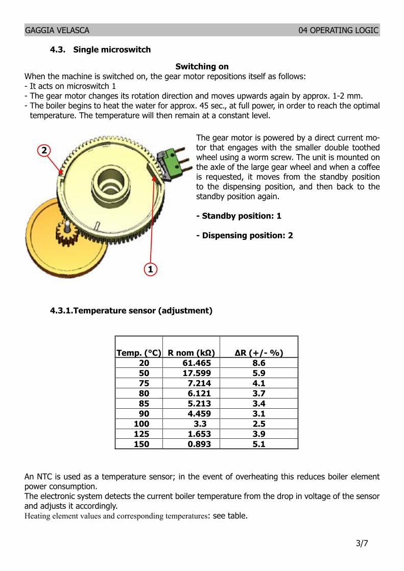
GAGGIA VELASCA 04 OPERATING LOGIC
77
49 AquaClean water filter
The AquaClean filter is designed to reduce limescale deposits in the coffee machine and provide filtered water to preserve the aroma and flavor of each cup of coffee By using a series of 8 AquaClean filters there is no need to descale the machine for 5000 cups (It depends both on the type of coffee used rinsing and cleaning programs) We recommend installing the water filter AquaClean the first use of the machine to the maximum before using 5 L of water The machine display will indicate when the filter needs to be replaced The maximum limit is equivalent to 110 L of water The conditions related to the filter work environment (water therefore an active environment for bacteria and microorganisms) require the replacement with a minimum frequency (we suggest 3 months from the activation to ensure the best performance) The filter startsrsquo working from the time is filled with water and continues working even with the machine off It cannot be deactivated manually as it must end its life cycle At the filter activation the display shows the icon with the percentage of use
- Initially 100 then decreasingWhen the autonomy of the current filter becomes less than 8 L of water the display shows
- The icon flashing slowly It means 10 When the autonomy of the current filter becomes less than 2 L of water the display shows
- The icon flashing quickly It means 0 After a maximum of 110 L of water supplied the flashing light turn off and the machine needs to be descaled
GAGGIA VELASCA
CHAPTER 5 SERVICE MODE
GAGGIA VELASCA 05 SERVICE MODE
18
51 Test Mode
IntroductionThis document describes the manual Test Mode of the GAGGIA VELASCA coffee appliance
To enter Test Mode To activate the manual Test Mode the user must press at the same time the ldquoEspressordquo and ldquoMenurdquo (ldquoSpecial Drinksrdquo for OTC version) buttons while connecting the CA to the power supplyOnce entered the Test Mode the first page of seven is shownEntering page the display shows a) The name of the machine and the installed firmware version b) The supply voltage c) The AC supply net frequency detected by the CAPage 1 Keyboard and display colors testing 1) Espresso button 2) Coffee button 3) Steam button (Aroma button for OTC version) 4) Hot Water button (Cappuccino button for OTC version) 5) Aroma button (Milk Froth button for OTC version) 6) Menu button (Special Drinks button for OTC version) 7) Stand-by button 8) Clean button (only OTC version) 9) Menu button (only OTC version)Page 2 Input signals testing a) Water tank sensor b) Door closedopened microswitch c) Coffee Brewing Unit insertion microswitch d) Dreg Drawer insertion microswitchPage 3 Coffee Brewing Unit testing a) UpDown BU movement (24V DC) b) BU effort currentPage 4 Hydraulic circuit loads testing (Pump Electrovalve) a) pump (120-230V AC) b) 2 ways Electrovalve (24Vdc)Page 5 Heater and Grinder testing a) Heater (120-230V AC) b) Grinder (320V DC)Page 6 Autodose quantities a) Light b) Med c) Strong
Test Mode INTELIA EVO V2 AMF
Filename Intelia_EVO2_AMF_TestMode_V05
50 G Divella 12062015 312 revNum Author Verified Approved SaveDate PPP
When accessing the Test Mode all the loads are turned off
11 Entering Page
Used to verify firmware version and some built-in parameters
This page shows the firmware version installed the supply voltage (230V or 120V) and the AC net frequency (50Hz or 60 Hz)
Itrsquos always required to check if the firmware version shown on the display is the same printed on the microcontroller label
Warning If the two version do not match the PCB must be dismissed
Press STEAMThe CA goes to page 1 (KEYB)
Test Mode INTELIA EVO V2 AMF
Filename Intelia_EVO2_AMF_TestMode_V05
50 G Divella 12062015 312 revNum Author Verified Approved SaveDate PPP
When accessing the Test Mode all the loads are turned off
11 Entering Page
Used to verify firmware version and some built-in parameters
This page shows the firmware version installed the supply voltage (230V or 120V) and the AC net frequency (50Hz or 60 Hz)
Itrsquos always required to check if the firmware version shown on the display is the same printed on the microcontroller label
Warning If the two version do not match the PCB must be dismissed
Press STEAMThe CA goes to page 1 (KEYB)
Test Mode INTELIA EVO V2 AMF
Filename Intelia_EVO2_AMF_TestMode_V05
50 G Divella 12062015 312 revNum Author Verified Approved SaveDate PPP
When accessing the Test Mode all the loads are turned off
11 Entering Page
Used to verify firmware version and some built-in parameters
This page shows the firmware version installed the supply voltage (230V or 120V) and the AC net frequency (50Hz or 60 Hz)
Itrsquos always required to check if the firmware version shown on the display is the same printed on the microcontroller label
Warning If the two version do not match the PCB must be dismissed
Press STEAMThe CA goes to page 1 (KEYB)
Test Mode INTELIA EVO V2 AMF
Filename Intelia_EVO2_AMF_TestMode_V05
50 G Divella 12062015 412 revNum Author Verified Approved SaveDate PPP
12 Page 1 (KEYB) Initial condition no button pressed
Press all the buttons from Ndeg1 till Ndeg9Whenever a button is pressed the ldquoONrdquo word appears near the related button number Pressing button Ndeg1 the backlight color switches from WHITE to REDPressing button Ndeg2 the backlight color switches from WHITE to PINK Pressing button Ndeg7 turns the STANDBY LED on To test button Ndeg4 it must be pressed just one time because it causes the CA to navigate to the next page
In case two or more buttons are pressed at the same time the display shows the expression ldquoTWO BTNrdquo This could be a useful warning if the keyboard is not working properly
ERRORS occur if ldquoONrdquo word does not appear or stays fixed on screen In this case itrsquos necessary to check the communication flat cable connected between the keyboard and the CPU-Power board Should not on the other hand change the display color check the JP5 cable
Pressing STEAM button The CA switches to page 2 (INPUTS)
Test Mode INTELIA EVO V2 AMF
Filename Intelia_EVO2_AMF_TestMode_V05
50 G Divella 12062015 412 revNum Author Verified Approved SaveDate PPP
12 Page 1 (KEYB) Initial condition no button pressed
Press all the buttons from Ndeg1 till Ndeg9Whenever a button is pressed the ldquoONrdquo word appears near the related button number Pressing button Ndeg1 the backlight color switches from WHITE to REDPressing button Ndeg2 the backlight color switches from WHITE to PINK Pressing button Ndeg7 turns the STANDBY LED on To test button Ndeg4 it must be pressed just one time because it causes the CA to navigate to the next page
In case two or more buttons are pressed at the same time the display shows the expression ldquoTWO BTNrdquo This could be a useful warning if the keyboard is not working properly
ERRORS occur if ldquoONrdquo word does not appear or stays fixed on screen In this case itrsquos necessary to check the communication flat cable connected between the keyboard and the CPU-Power board Should not on the other hand change the display color check the JP5 cable
Pressing STEAM button The CA switches to page 2 (INPUTS)
Test Mode INTELIA EVO V2 AMF
Filename Intelia_EVO2_AMF_TestMode_V05
50 G Divella 12062015 412 revNum Author Verified Approved SaveDate PPP
12 Page 1 (KEYB) Initial condition no button pressed
Press all the buttons from Ndeg1 till Ndeg9Whenever a button is pressed the ldquoONrdquo word appears near the related button number Pressing button Ndeg1 the backlight color switches from WHITE to REDPressing button Ndeg2 the backlight color switches from WHITE to PINK Pressing button Ndeg7 turns the STANDBY LED on To test button Ndeg4 it must be pressed just one time because it causes the CA to navigate to the next page
In case two or more buttons are pressed at the same time the display shows the expression ldquoTWO BTNrdquo This could be a useful warning if the keyboard is not working properly
ERRORS occur if ldquoONrdquo word does not appear or stays fixed on screen In this case itrsquos necessary to check the communication flat cable connected between the keyboard and the CPU-Power board Should not on the other hand change the display color check the JP5 cable
Pressing STEAM button The CA switches to page 2 (INPUTS)
Test Mode INTELIA EVO V2 AMF
Filename Intelia_EVO2_AMF_TestMode_V05
50 G Divella 12062015 312 revNum Author Verified Approved SaveDate PPP
When accessing the Test Mode all the loads are turned off
11 Entering Page
Used to verify firmware version and some built-in parameters
This page shows the firmware version installed the supply voltage (230V or 120V) and the AC net frequency (50Hz or 60 Hz)
Itrsquos always required to check if the firmware version shown on the display is the same printed on the microcontroller label
Warning If the two version do not match the PCB must be dismissed
Press STEAMThe CA goes to page 1 (KEYB)
GAGGIA VELASCA 05 SERVICE MODE
28
11 Entering Page
12 Page 1 (KEYB)
Verify the firmware version
This page shows the firmware version installed the supply voltage (230V or 120V) and the AC net frequency (50Hz or 60 Hz)
Itrsquos always required to check if the firmware version shown on the display is the same printed on the microcontroller label
WarningIf the two version do not match the PCB must be dismissed
Press STEAM (Press CAPPUCCINO for OTC version)
The CA goes to page 1 (KEYB)
Initial condition no button pressed
Press all the buttons from Ndeg1 till Ndeg9Whenever a button is pressed the ldquoONrdquo word appears near the related button numberPressing button Ndeg1 the backlight color switches from WHITE to REDPressing button Ndeg2 the backlight color switches from WHITE to PINKPressing button Ndeg7 turns the STANDBY LED onTo test button Ndeg4 it must be pressed just one time because it causes the CA to navigate to the next page
In case two or more buttons are pressed at the same time the display shows the expression ldquoTWO BTNrdquo This could be a useful warning if the keyboard is not working properly
ERRORS occur ifldquoONrdquo word does not appear or stays fixed on screen In this case itrsquos necessary to check the communication flat cable connected between the keyboard and the CPU-Power board Should not on the other hand change the display color check the JP5 cable
Test Mode INTELIA EVO V2 AMF
Filename Intelia_EVO2_AMF_TestMode_V05
50 G Divella 12062015 412 revNum Author Verified Approved SaveDate PPP
12 Page 1 (KEYB) Initial condition no button pressed
Press all the buttons from Ndeg1 till Ndeg9Whenever a button is pressed the ldquoONrdquo word appears near the related button number Pressing button Ndeg1 the backlight color switches from WHITE to REDPressing button Ndeg2 the backlight color switches from WHITE to PINK Pressing button Ndeg7 turns the STANDBY LED on To test button Ndeg4 it must be pressed just one time because it causes the CA to navigate to the next page
In case two or more buttons are pressed at the same time the display shows the expression ldquoTWO BTNrdquo This could be a useful warning if the keyboard is not working properly
ERRORS occur if ldquoONrdquo word does not appear or stays fixed on screen In this case itrsquos necessary to check the communication flat cable connected between the keyboard and the CPU-Power board Should not on the other hand change the display color check the JP5 cable
Pressing STEAM button The CA switches to page 2 (INPUTS)
Test Mode INTELIA EVO V2 AMF Filename
Intelia_EVO2_AMF_TestMode_V05
50 G Divella 12062015 512 revNum Author Verified Approved SaveDate PPP
13 Page 2 (INPUTS) Initial condition (having removed all the components)
Insert the tank full of waterThe H2O value must turn from ldquoNrdquo to ldquoYrdquo
ERRORS occur if If the H2O value doesnrsquot change check the capacitive sensor and the related wiring (JP23)
Insert the Dreg DrawerThe DREG value must turn from ldquoNrdquo to ldquoYrdquo
ERRORS occur if If the DREG value doesnrsquot change check the dreg drawer microswitch and the related wiring (JP16)
Close the Side Door (having the dreg drawer already inserted) The DOOR value must turn from ldquoNrdquo to ldquoYrdquo
ERRORS occur if If the DOOR value doesnrsquot change check the side door microswitch and the related wiring (JP14) and verify that the dreg drawer is correctly inserted
Test Mode INTELIA EVO V2 AMF Filename
Intelia_EVO2_AMF_TestMode_V05
50 G Divella 12062015 512 revNum Author Verified Approved SaveDate PPP
13 Page 2 (INPUTS) Initial condition (having removed all the components)
Insert the tank full of waterThe H2O value must turn from ldquoNrdquo to ldquoYrdquo
ERRORS occur if If the H2O value doesnrsquot change check the capacitive sensor and the related wiring (JP23)
Insert the Dreg DrawerThe DREG value must turn from ldquoNrdquo to ldquoYrdquo
ERRORS occur if If the DREG value doesnrsquot change check the dreg drawer microswitch and the related wiring (JP16)
Close the Side Door (having the dreg drawer already inserted) The DOOR value must turn from ldquoNrdquo to ldquoYrdquo
ERRORS occur if If the DOOR value doesnrsquot change check the side door microswitch and the related wiring (JP14) and verify that the dreg drawer is correctly inserted
Test Mode INTELIA EVO V2 AMF Filename
Intelia_EVO2_AMF_TestMode_V05
50 G Divella 12062015 512 revNum Author Verified Approved SaveDate PPP
13 Page 2 (INPUTS) Initial condition (having removed all the components)
Insert the tank full of waterThe H2O value must turn from ldquoNrdquo to ldquoYrdquo
ERRORS occur if If the H2O value doesnrsquot change check the capacitive sensor and the related wiring (JP23)
Insert the Dreg DrawerThe DREG value must turn from ldquoNrdquo to ldquoYrdquo
ERRORS occur if If the DREG value doesnrsquot change check the dreg drawer microswitch and the related wiring (JP16)
Close the Side Door (having the dreg drawer already inserted) The DOOR value must turn from ldquoNrdquo to ldquoYrdquo
ERRORS occur if If the DOOR value doesnrsquot change check the side door microswitch and the related wiring (JP14) and verify that the dreg drawer is correctly inserted Test Mode INTELIA EVO V2 AMF
Filename Intelia_EVO2_AMF_TestMode_V05
50 G Divella 12062015 612 revNum Author Verified Approved SaveDate PPP
Insert the Brewing Unit The BU-P value must turn from ldquoNrdquo to ldquoYrdquo
ERRORS occur if If the BU-P value doesnrsquot change check the BU presence microswitch and the related wiring (JP16)
Test Mode INTELIA EVO V2 AMF
Filename Intelia_EVO2_AMF_TestMode_V05
50 G Divella 12062015 412 revNum Author Verified Approved SaveDate PPP
12 Page 1 (KEYB) Initial condition no button pressed
Press all the buttons from Ndeg1 till Ndeg9Whenever a button is pressed the ldquoONrdquo word appears near the related button number Pressing button Ndeg1 the backlight color switches from WHITE to REDPressing button Ndeg2 the backlight color switches from WHITE to PINK Pressing button Ndeg7 turns the STANDBY LED on To test button Ndeg4 it must be pressed just one time because it causes the CA to navigate to the next page
In case two or more buttons are pressed at the same time the display shows the expression ldquoTWO BTNrdquo This could be a useful warning if the keyboard is not working properly
ERRORS occur if ldquoONrdquo word does not appear or stays fixed on screen In this case itrsquos necessary to check the communication flat cable connected between the keyboard and the CPU-Power board Should not on the other hand change the display color check the JP5 cable
Pressing STEAM button The CA switches to page 2 (INPUTS)
GAGGIA VELASCA 05 SERVICE MODE
38
13 Page 2 (INPUTS)
Insert the tank full of water
The H2O value must turn from ldquoNrdquo to ldquoYrdquo
ERRORS occur ifIf the H2O value doesnrsquot change check the capacitive sensor and the re-lated wiring (JP23)
Insert the Dreg Drawer
The DREG value must turn from ldquoNrdquo to ldquoYrdquo
ERRORS occur ifIf the DREG value doesnrsquot change check the dreg drawer microswitch and the related wiring (JP16)
Close the Side Door (having the dreg drawer already inserted)
The DOOR value must turn from ldquoNrdquo to ldquoYrdquo
ERRORS occur ifIf the DOOR value doesnrsquot change check the side door microswitch and the related wiring (JP14) and verify that the dreg drawer is correctly in-serted
Insert the Brewing Unit
The BU-P value must turn from ldquoNrdquo to ldquoYrdquo
ERRORS occur ifIf the BU-P value doesnrsquot change check the BU presence microswitch and the related wiring (JP16)
Initial condition (having removed all the components)
The CA switches to page 2 (INPUTS)
Pressing STEAM button (Press CAPPUCCINO for OTC version)
Test Mode INTELIA EVO V2 AMF Filename
Intelia_EVO2_AMF_TestMode_V05
50 G Divella 12062015 712 revNum Author Verified Approved SaveDate PPP
14 Page 3 (BU)
Initial condition
Press the ESPRESSO button to conduct the BU to the Work position When the BU reaches the work position the value WORK turns from ldquoNrdquo to ldquoYrdquo The absorbed BU current must be less than 200mA if the BU is not inserted and less than 300mA if the BU is inserted
ERRORS occur if The WORK value stays fixed on ldquoNrdquo while the backlight turns RED from WHITE in this case check the microswitch the BU engine (could be blocked) and finally the JP16 and JP14 wirings
ERROR (BU not inserted) If the absorbed current is more than 200 mA the display backlight turns red In this case check the gears of the engine and its standing in the housing
ERROR (BU inserted)If the absorbed current is more than 300 mA the display backlight turns red In this case check the gears of the engine and its standing in the housing
Test Mode INTELIA EVO V2 AMF Filename
Intelia_EVO2_AMF_TestMode_V05
50 G Divella 12062015 712 revNum Author Verified Approved SaveDate PPP
14 Page 3 (BU)
Initial condition
Press the ESPRESSO button to conduct the BU to the Work position When the BU reaches the work position the value WORK turns from ldquoNrdquo to ldquoYrdquo The absorbed BU current must be less than 200mA if the BU is not inserted and less than 300mA if the BU is inserted
ERRORS occur if The WORK value stays fixed on ldquoNrdquo while the backlight turns RED from WHITE in this case check the microswitch the BU engine (could be blocked) and finally the JP16 and JP14 wirings
ERROR (BU not inserted) If the absorbed current is more than 200 mA the display backlight turns red In this case check the gears of the engine and its standing in the housing
ERROR (BU inserted)If the absorbed current is more than 300 mA the display backlight turns red In this case check the gears of the engine and its standing in the housing
Test Mode INTELIA EVO V2 AMF Filename
Intelia_EVO2_AMF_TestMode_V05
50 G Divella 12062015 712 revNum Author Verified Approved SaveDate PPP
14 Page 3 (BU)
Initial condition
Press the ESPRESSO button to conduct the BU to the Work position When the BU reaches the work position the value WORK turns from ldquoNrdquo to ldquoYrdquo The absorbed BU current must be less than 200mA if the BU is not inserted and less than 300mA if the BU is inserted
ERRORS occur if The WORK value stays fixed on ldquoNrdquo while the backlight turns RED from WHITE in this case check the microswitch the BU engine (could be blocked) and finally the JP16 and JP14 wirings
ERROR (BU not inserted) If the absorbed current is more than 200 mA the display backlight turns red In this case check the gears of the engine and its standing in the housing
ERROR (BU inserted)If the absorbed current is more than 300 mA the display backlight turns red In this case check the gears of the engine and its standing in the housing
Test Mode INTELIA EVO V2 AMF Filename
Intelia_EVO2_AMF_TestMode_V05
50 G Divella 12062015 712 revNum Author Verified Approved SaveDate PPP
14 Page 3 (BU)
Initial condition
Press the ESPRESSO button to conduct the BU to the Work position When the BU reaches the work position the value WORK turns from ldquoNrdquo to ldquoYrdquo The absorbed BU current must be less than 200mA if the BU is not inserted and less than 300mA if the BU is inserted
ERRORS occur if The WORK value stays fixed on ldquoNrdquo while the backlight turns RED from WHITE in this case check the microswitch the BU engine (could be blocked) and finally the JP16 and JP14 wirings
ERROR (BU not inserted) If the absorbed current is more than 200 mA the display backlight turns red In this case check the gears of the engine and its standing in the housing
ERROR (BU inserted)If the absorbed current is more than 300 mA the display backlight turns red In this case check the gears of the engine and its standing in the housing
Test Mode INTELIA EVO V2 AMF Filename
Intelia_EVO2_AMF_TestMode_V05
50 G Divella 12062015 712 revNum Author Verified Approved SaveDate PPP
14 Page 3 (BU)
Initial condition
Press the ESPRESSO button to conduct the BU to the Work position When the BU reaches the work position the value WORK turns from ldquoNrdquo to ldquoYrdquo The absorbed BU current must be less than 200mA if the BU is not inserted and less than 300mA if the BU is inserted
ERRORS occur if The WORK value stays fixed on ldquoNrdquo while the backlight turns RED from WHITE in this case check the microswitch the BU engine (could be blocked) and finally the JP16 and JP14 wirings
ERROR (BU not inserted) If the absorbed current is more than 200 mA the display backlight turns red In this case check the gears of the engine and its standing in the housing
ERROR (BU inserted)If the absorbed current is more than 300 mA the display backlight turns red In this case check the gears of the engine and its standing in the housing
Test Mode INTELIA EVO V2 AMF Filename
Intelia_EVO2_AMF_TestMode_V05
50 G Divella 12062015 812 revNum Author Verified Approved SaveDate PPP
Press the COFFEE button to move the BU towards the HOME position When the BU reaches the HOME position the HOME value changes from ldquoNrdquo to ldquoYrdquo The maximum absorbed current must be less than 200 mA (BU not inserted) 300 mA (BU inserted)
ERRORS occur if The HOME value stays fixed on ldquoNrdquo while the backlight turns RED from WHITE in this case check the microswitch the BU engine (could be blocked) and finally the JP16 and JP14 wirings
ERROR (BU not inserted) If the absorbed current is more than 200 mA the display backlight turns red In this case check the gears of the engine and its standing in the housing
ERROR (BU inserted)If the absorbed current is more than 300 mA the display backlight turns red In this case check the gears of the engine and its standing in the housing
Press the STEAM button The CA goes to the EVPUMP page (EV - PUMP)
Test Mode INTELIA EVO V2 AMF Filename
Intelia_EVO2_AMF_TestMode_V05
50 G Divella 12062015 812 revNum Author Verified Approved SaveDate PPP
Press the COFFEE button to move the BU towards the HOME position When the BU reaches the HOME position the HOME value changes from ldquoNrdquo to ldquoYrdquo The maximum absorbed current must be less than 200 mA (BU not inserted) 300 mA (BU inserted)
ERRORS occur if The HOME value stays fixed on ldquoNrdquo while the backlight turns RED from WHITE in this case check the microswitch the BU engine (could be blocked) and finally the JP16 and JP14 wirings
ERROR (BU not inserted) If the absorbed current is more than 200 mA the display backlight turns red In this case check the gears of the engine and its standing in the housing
ERROR (BU inserted)If the absorbed current is more than 300 mA the display backlight turns red In this case check the gears of the engine and its standing in the housing
Press the STEAM button The CA goes to the EVPUMP page (EV - PUMP)
Test Mode INTELIA EVO V2 AMF Filename
Intelia_EVO2_AMF_TestMode_V05
50 G Divella 12062015 812 revNum Author Verified Approved SaveDate PPP
Press the COFFEE button to move the BU towards the HOME position When the BU reaches the HOME position the HOME value changes from ldquoNrdquo to ldquoYrdquo The maximum absorbed current must be less than 200 mA (BU not inserted) 300 mA (BU inserted)
ERRORS occur if The HOME value stays fixed on ldquoNrdquo while the backlight turns RED from WHITE in this case check the microswitch the BU engine (could be blocked) and finally the JP16 and JP14 wirings
ERROR (BU not inserted) If the absorbed current is more than 200 mA the display backlight turns red In this case check the gears of the engine and its standing in the housing
ERROR (BU inserted)If the absorbed current is more than 300 mA the display backlight turns red In this case check the gears of the engine and its standing in the housing
Press the STEAM button The CA goes to the EVPUMP page (EV - PUMP)
Test Mode INTELIA EVO V2 AMF Filename
Intelia_EVO2_AMF_TestMode_V05
50 G Divella 12062015 812 revNum Author Verified Approved SaveDate PPP
Press the COFFEE button to move the BU towards the HOME position When the BU reaches the HOME position the HOME value changes from ldquoNrdquo to ldquoYrdquo The maximum absorbed current must be less than 200 mA (BU not inserted) 300 mA (BU inserted)
ERRORS occur if The HOME value stays fixed on ldquoNrdquo while the backlight turns RED from WHITE in this case check the microswitch the BU engine (could be blocked) and finally the JP16 and JP14 wirings
ERROR (BU not inserted) If the absorbed current is more than 200 mA the display backlight turns red In this case check the gears of the engine and its standing in the housing
ERROR (BU inserted)If the absorbed current is more than 300 mA the display backlight turns red In this case check the gears of the engine and its standing in the housing
Press the STEAM button The CA goes to the EVPUMP page (EV - PUMP)
Test Mode INTELIA EVO V2 AMF Filename
Intelia_EVO2_AMF_TestMode_V05
50 G Divella 12062015 812 revNum Author Verified Approved SaveDate PPP
Press the COFFEE button to move the BU towards the HOME position When the BU reaches the HOME position the HOME value changes from ldquoNrdquo to ldquoYrdquo The maximum absorbed current must be less than 200 mA (BU not inserted) 300 mA (BU inserted)
ERRORS occur if The HOME value stays fixed on ldquoNrdquo while the backlight turns RED from WHITE in this case check the microswitch the BU engine (could be blocked) and finally the JP16 and JP14 wirings
ERROR (BU not inserted) If the absorbed current is more than 200 mA the display backlight turns red In this case check the gears of the engine and its standing in the housing
ERROR (BU inserted)If the absorbed current is more than 300 mA the display backlight turns red In this case check the gears of the engine and its standing in the housing
Press the STEAM button The CA goes to the EVPUMP page (EV - PUMP)
GAGGIA VELASCA 05 SERVICE MODE
48
14 Page 3 (BU)
Press the ESPRESSO button to conduct the BU to the Work position
When the BU reaches the work position the value WORK turns from ldquoNrdquo to ldquoYrdquo The absorbed BU current must be less than 200mA if the BU is not inserted and less than 300mA if the BU is inserted
ERRORS occur ifThe WORK value stays fixed on ldquoNrdquo while the backlight turns RED from WHITE in this case check the microswitch the BU engine (could be blocked) and finally the JP16 and JP14 wiringsERROR (BU not inserted)If the absorbed current is more than 200 mA the display backlight turns red In this case check the gears of the engine and its standing in the housingERROR (BU inserted)If the absorbed current is more than 300 mA the display backlight turns red In this case check the gears of the engine and its standing in the housing
Press the COFFEE button to move the BU towards the HOME position
When the BU reaches the HOME position the HOME value changes from ldquoNrdquo to ldquoYrdquo The maximum absorbed current must be less than 200 mA (BU not inserted) 300 mA (BU inserted)
ERRORS occur ifThe HOME value stays fixed on ldquoNrdquo while the backlight turns RED from WHITE in this case check the microswitch the BU engine (could be blocked) and finally the JP16 and JP14 wiringsERROR (BU not inserted)If the absorbed current is more than 200 mA the display backlight turns red In this case check the gears of the engine and its standing in the housingERROR (BU inserted)If the absorbed current is more than 300 mA the display backlight turns red In this case check the gears of the engine and its standing in the housing
Press the STEAM button (Press CAPPUCCINO for OTC version)
The CA goes to the EVPUMP page (EV - PUMP)
Initial condition
Test Mode INTELIA EVO V2 AMF Filename
Intelia_EVO2_AMF_TestMode_V05
50 G Divella 12062015 912 revNum Author Verified Approved SaveDate PPP
15 Page 4 (EV - PUMP)
Should this page been shown it means either the dreg drawer is not correctly inserted or the side door not closed Only solving both these issues it would be possible to come out from this screen
Press the ESPRESSO button to activate the 2-ways Electrovalve (closed by default) The Electrovalve is activated so the EV1 value turns from ldquoOFFrdquo to ldquoONrdquo
Press the HOT WATER button to activate the PumpThe water now flows out from the spout causing the update of the IMP value with the number of flowmeter impulses The LH value must stay within 10lh and 18 lh
ERROR If the number of impulses remains 0 and the display backlight turns red it means that therersquos an error in the hydraulic circuit If water comes out from the spout it means that therersquos an error in the flowmeter or in its wiring to the CPUPOWER (JP5) if on the other hand no water comes out itrsquos necessary to check the pump or the hydraulic circuit or the pump wiring (JP24)
Press the STEAM WATER button The CA shows the HeaterGrinder page (Heater-Grinder)
16 Page5 (Heater-Grinder)
Test Mode INTELIA EVO V2 AMF Filename
Intelia_EVO2_AMF_TestMode_V05
50 G Divella 12062015 912 revNum Author Verified Approved SaveDate PPP
15 Page 4 (EV - PUMP)
Should this page been shown it means either the dreg drawer is not correctly inserted or the side door not closed Only solving both these issues it would be possible to come out from this screen
Press the ESPRESSO button to activate the 2-ways Electrovalve (closed by default) The Electrovalve is activated so the EV1 value turns from ldquoOFFrdquo to ldquoONrdquo
Press the HOT WATER button to activate the PumpThe water now flows out from the spout causing the update of the IMP value with the number of flowmeter impulses The LH value must stay within 10lh and 18 lh
ERROR If the number of impulses remains 0 and the display backlight turns red it means that therersquos an error in the hydraulic circuit If water comes out from the spout it means that therersquos an error in the flowmeter or in its wiring to the CPUPOWER (JP5) if on the other hand no water comes out itrsquos necessary to check the pump or the hydraulic circuit or the pump wiring (JP24)
Press the STEAM WATER button The CA shows the HeaterGrinder page (Heater-Grinder)
16 Page5 (Heater-Grinder)
Test Mode INTELIA EVO V2 AMF Filename
Intelia_EVO2_AMF_TestMode_V05
50 G Divella 12062015 912 revNum Author Verified Approved SaveDate PPP
15 Page 4 (EV - PUMP)
Should this page been shown it means either the dreg drawer is not correctly inserted or the side door not closed Only solving both these issues it would be possible to come out from this screen
Press the ESPRESSO button to activate the 2-ways Electrovalve (closed by default) The Electrovalve is activated so the EV1 value turns from ldquoOFFrdquo to ldquoONrdquo
Press the HOT WATER button to activate the PumpThe water now flows out from the spout causing the update of the IMP value with the number of flowmeter impulses The LH value must stay within 10lh and 18 lh
ERROR If the number of impulses remains 0 and the display backlight turns red it means that therersquos an error in the hydraulic circuit If water comes out from the spout it means that therersquos an error in the flowmeter or in its wiring to the CPUPOWER (JP5) if on the other hand no water comes out itrsquos necessary to check the pump or the hydraulic circuit or the pump wiring (JP24)
Press the STEAM WATER button The CA shows the HeaterGrinder page (Heater-Grinder)
16 Page5 (Heater-Grinder)
Test Mode INTELIA EVO V2 AMF Filename
Intelia_EVO2_AMF_TestMode_V05
50 G Divella 12062015 912 revNum Author Verified Approved SaveDate PPP
15 Page 4 (EV - PUMP)
Should this page been shown it means either the dreg drawer is not correctly inserted or the side door not closed Only solving both these issues it would be possible to come out from this screen
Press the ESPRESSO button to activate the 2-ways Electrovalve (closed by default) The Electrovalve is activated so the EV1 value turns from ldquoOFFrdquo to ldquoONrdquo
Press the HOT WATER button to activate the PumpThe water now flows out from the spout causing the update of the IMP value with the number of flowmeter impulses The LH value must stay within 10lh and 18 lh
ERROR If the number of impulses remains 0 and the display backlight turns red it means that therersquos an error in the hydraulic circuit If water comes out from the spout it means that therersquos an error in the flowmeter or in its wiring to the CPUPOWER (JP5) if on the other hand no water comes out itrsquos necessary to check the pump or the hydraulic circuit or the pump wiring (JP24)
Press the STEAM WATER button The CA shows the HeaterGrinder page (Heater-Grinder)
16 Page5 (Heater-Grinder)
Test Mode INTELIA EVO V2 AMF Filename
Intelia_EVO2_AMF_TestMode_V05
50 G Divella 12062015 912 revNum Author Verified Approved SaveDate PPP
15 Page 4 (EV - PUMP)
Should this page been shown it means either the dreg drawer is not correctly inserted or the side door not closed Only solving both these issues it would be possible to come out from this screen
Press the ESPRESSO button to activate the 2-ways Electrovalve (closed by default) The Electrovalve is activated so the EV1 value turns from ldquoOFFrdquo to ldquoONrdquo
Press the HOT WATER button to activate the PumpThe water now flows out from the spout causing the update of the IMP value with the number of flowmeter impulses The LH value must stay within 10lh and 18 lh
ERROR If the number of impulses remains 0 and the display backlight turns red it means that therersquos an error in the hydraulic circuit If water comes out from the spout it means that therersquos an error in the flowmeter or in its wiring to the CPUPOWER (JP5) if on the other hand no water comes out itrsquos necessary to check the pump or the hydraulic circuit or the pump wiring (JP24)
Press the STEAM WATER button The CA shows the HeaterGrinder page (Heater-Grinder)
16 Page5 (Heater-Grinder)
Test Mode INTELIA EVO V2 AMF Filename
Intelia_EVO2_AMF_TestMode_V05
50 G Divella 12062015 912 revNum Author Verified Approved SaveDate PPP
15 Page 4 (EV - PUMP)
Should this page been shown it means either the dreg drawer is not correctly inserted or the side door not closed Only solving both these issues it would be possible to come out from this screen
Press the ESPRESSO button to activate the 2-ways Electrovalve (closed by default) The Electrovalve is activated so the EV1 value turns from ldquoOFFrdquo to ldquoONrdquo
Press the HOT WATER button to activate the PumpThe water now flows out from the spout causing the update of the IMP value with the number of flowmeter impulses The LH value must stay within 10lh and 18 lh
ERROR If the number of impulses remains 0 and the display backlight turns red it means that therersquos an error in the hydraulic circuit If water comes out from the spout it means that therersquos an error in the flowmeter or in its wiring to the CPUPOWER (JP5) if on the other hand no water comes out itrsquos necessary to check the pump or the hydraulic circuit or the pump wiring (JP24)
Press the STEAM WATER button The CA shows the HeaterGrinder page (Heater-Grinder)
16 Page5 (Heater-Grinder)
Test Mode INTELIA EVO V2 AMF Filename
Intelia_EVO2_AMF_TestMode_V05
50 G Divella 12062015 1012 revNum Author Verified Approved SaveDate PPP
Initial condition
Press the HOT WATER button to activate the GrinderThe coffee grinder starts milling for 5000 ms if the user doesnrsquot release the button before In this case the activation time is shown in the red-circled field of the picture
ERROR If this number keeps fixed at 0 the display turns red and the engine moves then there must be a fault in the grinder wiring (JP8) or in the grinder itself
Keep pressed STANDBY for 5 secs to reset grinder parameters Pressing button STANDBY for 5 secs resets grinder parameters
Test Mode INTELIA EVO V2 AMF Filename
Intelia_EVO2_AMF_TestMode_V05
50 G Divella 12062015 1012 revNum Author Verified Approved SaveDate PPP
Initial condition
Press the HOT WATER button to activate the GrinderThe coffee grinder starts milling for 5000 ms if the user doesnrsquot release the button before In this case the activation time is shown in the red-circled field of the picture
ERROR If this number keeps fixed at 0 the display turns red and the engine moves then there must be a fault in the grinder wiring (JP8) or in the grinder itself
Keep pressed STANDBY for 5 secs to reset grinder parameters Pressing button STANDBY for 5 secs resets grinder parameters
Test Mode INTELIA EVO V2 AMF Filename
Intelia_EVO2_AMF_TestMode_V05
50 G Divella 12062015 1012 revNum Author Verified Approved SaveDate PPP
Initial condition
Press the HOT WATER button to activate the GrinderThe coffee grinder starts milling for 5000 ms if the user doesnrsquot release the button before In this case the activation time is shown in the red-circled field of the picture
ERROR If this number keeps fixed at 0 the display turns red and the engine moves then there must be a fault in the grinder wiring (JP8) or in the grinder itself
Keep pressed STANDBY for 5 secs to reset grinder parameters Pressing button STANDBY for 5 secs resets grinder parameters
GAGGIA VELASCA 05 SERVICE MODE
58
15 Page 4 (EV - PUMP)
Press the ESPRESSO button to activate the 2-ways Electrovalve (closed by default)
The Electrovalve is activated so the EV1 value turns from ldquoOFFrdquo to ldquoONrdquo
Press the HOT WATER (Press MILK for OTC version) button to activate the Pump
The water now flows out from the spout causing the update of the IMP value with the number of flowmeter impulses The LH value must stay within 10lh and 18 lh
ERRORIf the number of impulses remains 0 and the display backlight turns red it means that therersquos an error in the hydraulic circuit If water comes out from the spout it means that therersquos an error in the flowmeter or in its wiring to the CPUPOWER (JP5) if on the other hand no water comes out itrsquos necessary to check the pump or the hydraulic circuit or the pump wiring (JP24)
Press the STEAM WATER button (Press CAPPUCCINO for OTC version)
The CA shows the HeaterGrinder page (Heater-Grinder)
Initial condition
Press the HOT WATER (Press MILK for OTC version) button to activate the Grinder
The coffee grinder starts milling for 5000 ms In this case the activation time is shown in the red-circled field of the picture
ERRORIf this number keeps fixed at 0or the grinder does not run the display turns red this means there must be a fault in the grinder wiring (JP8) or in the grinder itself or in the electronic board
Keep pressed STANDBY for 5 secs to reset grinder parameters
Pressing button STANDBY for 5 secs resets grinder parametersThis action is needed if the grinder has been replaced
Should this page been shown it means either the dreg drawer is not cor-rectly inserted or the side door not closed Only solving both these issues it would be possible to come out from this screen
16 Page 5 (Heater-Grinder)
Test Mode INTELIA EVO V2 AMF Filename
Intelia_EVO2_AMF_TestMode_V05
50 G Divella 12062015 1112 revNum Author Verified Approved SaveDate PPP
Heater Temperature monitoring The red-circled number shows the heater temperature in Celsius degrees
ERROR If inside the HEATER column appears the word ldquoSHORTrdquo then the NTC sensor is in a short-circuit state The display backlight turns RED from WHITE in this case the NTC wiring or the input CPUPOWER (JP13) must be checked
ERROR If inside the HEATER column appears the word ldquoOPENrdquo then the NTC sensor is disconnected The display backlight turns RED from WHITE In this case the connectivity of the NTC wiring to the CPUPOWER (JP13) must be checked
Press the COFFEE button to activate the heaterThe label switches from ldquoOFFrdquo to ldquoONrdquo and the number indicating the temperature starts to increase (and so the current absorbed by the CA on the power supply ndash ca 8 A 230V) For safety reasons it is possible to activate the heater keeping pressed the button for a maximum time of 5 seconds
Therersquos a further check on the temperature level should it rise over 120degC the display backlight turns pink and an alarm message appears In this scenario the heater is forced to stay turned off to avoid dangerous over-temperatures
ERROR If therersquos no temperature increasing the user must check the heater resistance its wiring to the CPUPOWER (JP19) and also the NTC wiring (JP13)
Press both the AROMA and the MENU buttons These values appear on the display
Grinding time applied during last mill Average of the low state duration of the current sensor
signal Threshold for the presenceabsence coffee detection
Test Mode INTELIA EVO V2 AMF Filename
Intelia_EVO2_AMF_TestMode_V05
50 G Divella 12062015 1112 revNum Author Verified Approved SaveDate PPP
Heater Temperature monitoring The red-circled number shows the heater temperature in Celsius degrees
ERROR If inside the HEATER column appears the word ldquoSHORTrdquo then the NTC sensor is in a short-circuit state The display backlight turns RED from WHITE in this case the NTC wiring or the input CPUPOWER (JP13) must be checked
ERROR If inside the HEATER column appears the word ldquoOPENrdquo then the NTC sensor is disconnected The display backlight turns RED from WHITE In this case the connectivity of the NTC wiring to the CPUPOWER (JP13) must be checked
Press the COFFEE button to activate the heaterThe label switches from ldquoOFFrdquo to ldquoONrdquo and the number indicating the temperature starts to increase (and so the current absorbed by the CA on the power supply ndash ca 8 A 230V) For safety reasons it is possible to activate the heater keeping pressed the button for a maximum time of 5 seconds
Therersquos a further check on the temperature level should it rise over 120degC the display backlight turns pink and an alarm message appears In this scenario the heater is forced to stay turned off to avoid dangerous over-temperatures
ERROR If therersquos no temperature increasing the user must check the heater resistance its wiring to the CPUPOWER (JP19) and also the NTC wiring (JP13)
Press both the AROMA and the MENU buttons These values appear on the display
Grinding time applied during last mill Average of the low state duration of the current sensor
signal Threshold for the presenceabsence coffee detection
Test Mode INTELIA EVO V2 AMF Filename
Intelia_EVO2_AMF_TestMode_V05
50 G Divella 12062015 1112 revNum Author Verified Approved SaveDate PPP
Heater Temperature monitoring The red-circled number shows the heater temperature in Celsius degrees
ERROR If inside the HEATER column appears the word ldquoSHORTrdquo then the NTC sensor is in a short-circuit state The display backlight turns RED from WHITE in this case the NTC wiring or the input CPUPOWER (JP13) must be checked
ERROR If inside the HEATER column appears the word ldquoOPENrdquo then the NTC sensor is disconnected The display backlight turns RED from WHITE In this case the connectivity of the NTC wiring to the CPUPOWER (JP13) must be checked
Press the COFFEE button to activate the heaterThe label switches from ldquoOFFrdquo to ldquoONrdquo and the number indicating the temperature starts to increase (and so the current absorbed by the CA on the power supply ndash ca 8 A 230V) For safety reasons it is possible to activate the heater keeping pressed the button for a maximum time of 5 seconds
Therersquos a further check on the temperature level should it rise over 120degC the display backlight turns pink and an alarm message appears In this scenario the heater is forced to stay turned off to avoid dangerous over-temperatures
ERROR If therersquos no temperature increasing the user must check the heater resistance its wiring to the CPUPOWER (JP19) and also the NTC wiring (JP13)
Press both the AROMA and the MENU buttons These values appear on the display
Grinding time applied during last mill Average of the low state duration of the current sensor
signal Threshold for the presenceabsence coffee detection
Test Mode INTELIA EVO V2 AMF Filename
Intelia_EVO2_AMF_TestMode_V05
50 G Divella 12062015 1112 revNum Author Verified Approved SaveDate PPP
Heater Temperature monitoring The red-circled number shows the heater temperature in Celsius degrees
ERROR If inside the HEATER column appears the word ldquoSHORTrdquo then the NTC sensor is in a short-circuit state The display backlight turns RED from WHITE in this case the NTC wiring or the input CPUPOWER (JP13) must be checked
ERROR If inside the HEATER column appears the word ldquoOPENrdquo then the NTC sensor is disconnected The display backlight turns RED from WHITE In this case the connectivity of the NTC wiring to the CPUPOWER (JP13) must be checked
Press the COFFEE button to activate the heaterThe label switches from ldquoOFFrdquo to ldquoONrdquo and the number indicating the temperature starts to increase (and so the current absorbed by the CA on the power supply ndash ca 8 A 230V) For safety reasons it is possible to activate the heater keeping pressed the button for a maximum time of 5 seconds
Therersquos a further check on the temperature level should it rise over 120degC the display backlight turns pink and an alarm message appears In this scenario the heater is forced to stay turned off to avoid dangerous over-temperatures
ERROR If therersquos no temperature increasing the user must check the heater resistance its wiring to the CPUPOWER (JP19) and also the NTC wiring (JP13)
Press both the AROMA and the MENU buttons These values appear on the display
Grinding time applied during last mill Average of the low state duration of the current sensor
signal Threshold for the presenceabsence coffee detection
Test Mode INTELIA EVO V2 AMF Filename
Intelia_EVO2_AMF_TestMode_V05
50 G Divella 12062015 1112 revNum Author Verified Approved SaveDate PPP
Heater Temperature monitoring The red-circled number shows the heater temperature in Celsius degrees
ERROR If inside the HEATER column appears the word ldquoSHORTrdquo then the NTC sensor is in a short-circuit state The display backlight turns RED from WHITE in this case the NTC wiring or the input CPUPOWER (JP13) must be checked
ERROR If inside the HEATER column appears the word ldquoOPENrdquo then the NTC sensor is disconnected The display backlight turns RED from WHITE In this case the connectivity of the NTC wiring to the CPUPOWER (JP13) must be checked
Press the COFFEE button to activate the heaterThe label switches from ldquoOFFrdquo to ldquoONrdquo and the number indicating the temperature starts to increase (and so the current absorbed by the CA on the power supply ndash ca 8 A 230V) For safety reasons it is possible to activate the heater keeping pressed the button for a maximum time of 5 seconds
Therersquos a further check on the temperature level should it rise over 120degC the display backlight turns pink and an alarm message appears In this scenario the heater is forced to stay turned off to avoid dangerous over-temperatures
ERROR If therersquos no temperature increasing the user must check the heater resistance its wiring to the CPUPOWER (JP19) and also the NTC wiring (JP13)
Press both the AROMA and the MENU buttons These values appear on the display
Grinding time applied during last mill Average of the low state duration of the current sensor
signal Threshold for the presenceabsence coffee detection
Test Mode INTELIA EVO V2 AMF Filename
Intelia_EVO2_AMF_TestMode_V05
50 G Divella 12062015 1112 revNum Author Verified Approved SaveDate PPP
Heater Temperature monitoring The red-circled number shows the heater temperature in Celsius degrees
ERROR If inside the HEATER column appears the word ldquoSHORTrdquo then the NTC sensor is in a short-circuit state The display backlight turns RED from WHITE in this case the NTC wiring or the input CPUPOWER (JP13) must be checked
ERROR If inside the HEATER column appears the word ldquoOPENrdquo then the NTC sensor is disconnected The display backlight turns RED from WHITE In this case the connectivity of the NTC wiring to the CPUPOWER (JP13) must be checked
Press the COFFEE button to activate the heaterThe label switches from ldquoOFFrdquo to ldquoONrdquo and the number indicating the temperature starts to increase (and so the current absorbed by the CA on the power supply ndash ca 8 A 230V) For safety reasons it is possible to activate the heater keeping pressed the button for a maximum time of 5 seconds
Therersquos a further check on the temperature level should it rise over 120degC the display backlight turns pink and an alarm message appears In this scenario the heater is forced to stay turned off to avoid dangerous over-temperatures
ERROR If therersquos no temperature increasing the user must check the heater resistance its wiring to the CPUPOWER (JP19) and also the NTC wiring (JP13)
Press both the AROMA and the MENU buttons These values appear on the display
Grinding time applied during last mill Average of the low state duration of the current sensor
signal Threshold for the presenceabsence coffee detection
Test Mode INTELIA EVO V2 AMF Filename
Intelia_EVO2_AMF_TestMode_V05
50 G Divella 12062015 1212 revNum Author Verified Approved SaveDate PPP
Press the STEAM button The CA shows the Autodoses page
17 Page 6 (Autodoses) The CA shows the AUTODOSES page with the time of milling for the different coffee aroma
Light Med Strong
Test Mode INTELIA EVO V2 AMF Filename
Intelia_EVO2_AMF_TestMode_V05
50 G Divella 12062015 1212 revNum Author Verified Approved SaveDate PPP
Press the STEAM button The CA shows the Autodoses page
17 Page 6 (Autodoses) The CA shows the AUTODOSES page with the time of milling for the different coffee aroma
Light Med Strong
GAGGIA VELASCA 05 SERVICE MODE
68
Heater Temperature monitoring
The red-circled number shows the heater temperature in Celsius degrees
ERRORIf inside the HEATER column appears the word ldquoSHORTrdquo then the NTC sensor is in a short-circuit state The display backlight turns RED from WHITE in this case the NTC wiring or the input CPUPOWER (JP13) must be checkedERRORIf inside the HEATER column appears the word ldquoOPENrdquo then the NTC sensor is disconnected The display backlight turns RED from WHITE In this case the connectivity of the NTC wiring to the CPUPOWER (JP13) must be checked
Press the COFFEE button to activate the heaterThe label switches from ldquoOFFrdquo to ldquoONrdquo and the number indicating the temperature starts to increase (and so the current absorbed by the CA on the power supply ndash ca 8 A 230V)For safety reasons it is possible to activate the heater keeping pressed the button for a maximum time of 5 secondsTherersquos a further check on the temperature level should it rise over 120degC the display backlight turns pink and an alarm message appears In this scenario the heater is forced to stay turned off to avoid dangerous over-temperatures
ERRORIf therersquos no temperature increasing the user must check the heater re-sistance its wiring to the CPUPOWER (JP19) and also the NTC wiring (JP13)
Press both the AROMA and the MENU(CMF-AMF version)SPECIALS(OTC version) buttonsThis page shows extended info Check of these number is not requestedFollowing values appear on the displaybull Grinding time applied during last millbull Average of the low state duration of the current sensor signalbull Threshold for the presenceabsence coffee detection
Press the STEAM button (Press CAPPUCCINO for OTC version)
The CA shows the Autodoses page
The CA shows the AUTODOSES page with the time of milling for the dif-ferent coffee aromabull Lightbull Medbull Strong
17 Page 6 (Autodoses)
Steam Out Intelia EVO 2 OTCAMF
Filename
Intelia_EVO2_Stea
m_Out_V03doc
03 G Divella 02072015 23
revNum Editor Verified By Approved By SaveDate PPP
Introduction
This document describes the Steam-Out process that is executed at the end of the production line for the CA
INTELIA EVO 2 OTCAMF It totally empties the heater from any residual water and resets some parameters
to the factory default values
1 Steam Out
To access Steam Out the user must press both LONG COFFEE and SPECIAL DRINKS (MENU for AMF)
buttons while connecting the CA to the power supply
When lit the CA will start the procedure turning PINK the display
backlight and showing ldquoONrdquo on the screen-
During the process the 2-ways Electrovalve will stay open causing
steam to be discharged from the spout (hot water wand for AMF
version)
Warning
If the dreg drawer is not correctly inserted or the side door open the
CA shows a RED screen with the advice ldquoCLOSE DOOR amp DREGSrdquo
At the end of the process the display will turn WHITE and show the
ldquoCOMPLETErdquo word on the screen The Electrovalve also will be
closed and the CA will be ready to be manually turned off
Steam Out Intelia EVO 2 OTCAMF
Filename
Intelia_EVO2_Stea
m_Out_V03doc
03 G Divella 02072015 23
revNum Editor Verified By Approved By SaveDate PPP
Introduction
This document describes the Steam-Out process that is executed at the end of the production line for the CA
INTELIA EVO 2 OTCAMF It totally empties the heater from any residual water and resets some parameters
to the factory default values
1 Steam Out
To access Steam Out the user must press both LONG COFFEE and SPECIAL DRINKS (MENU for AMF)
buttons while connecting the CA to the power supply
When lit the CA will start the procedure turning PINK the display
backlight and showing ldquoONrdquo on the screen-
During the process the 2-ways Electrovalve will stay open causing
steam to be discharged from the spout (hot water wand for AMF
version)
Warning
If the dreg drawer is not correctly inserted or the side door open the
CA shows a RED screen with the advice ldquoCLOSE DOOR amp DREGSrdquo
At the end of the process the display will turn WHITE and show the
ldquoCOMPLETErdquo word on the screen The Electrovalve also will be
closed and the CA will be ready to be manually turned off
Steam Out Intelia EVO 2 OTCAMF
Filename
Intelia_EVO2_Stea
m_Out_V03doc
03 G Divella 02072015 23
revNum Editor Verified By Approved By SaveDate PPP
Introduction
This document describes the Steam-Out process that is executed at the end of the production line for the CA
INTELIA EVO 2 OTCAMF It totally empties the heater from any residual water and resets some parameters
to the factory default values
1 Steam Out
To access Steam Out the user must press both LONG COFFEE and SPECIAL DRINKS (MENU for AMF)
buttons while connecting the CA to the power supply
When lit the CA will start the procedure turning PINK the display
backlight and showing ldquoONrdquo on the screen-
During the process the 2-ways Electrovalve will stay open causing
steam to be discharged from the spout (hot water wand for AMF
version)
Warning
If the dreg drawer is not correctly inserted or the side door open the
CA shows a RED screen with the advice ldquoCLOSE DOOR amp DREGSrdquo
At the end of the process the display will turn WHITE and show the
ldquoCOMPLETErdquo word on the screen The Electrovalve also will be
closed and the CA will be ready to be manually turned off
GAGGIA VELASCA 05 SERVICE MODE
78
52 Steam Out
Not mandatory but if necessary before executing the steam out procedure descale the machine taking care to remouve the Aquaclean filter from the applianceIn case the filter on the machine is active (or itrsquos in the machine) provide the consumer with a new one
IntroductionThis document describes the Steam-Out process that is executed at the end of the production line for the CA GAGGIA VELASCA It totally empties the heater from any residual water and resets some parameters to the factory default values
Steam OutTo access Steam Out the user must press both LONG COFFEE and SPECIAL DRINKS (MENU for AMF)buttons while connecting the CA to the power supply
The Steam-Out resets these parameters to their factory values
OTC version product quantitiesShort Coffee (Espresso) Long Coffee Coffee Intense Coffee in cappuccino Milk in cappuccino Froth Milk brewing time
AMF version product quantitiesShort Coffee (Espresso) Long Coffee
Longevity Filter setupFilter Startup Quantity Filter Counter Filter Remaining Autonomy Filter Installation proposal at start
CA SettingsPre-infusion
impulses = 137impulses = 330impulses = 265 (brewed within two mill-brew cycles)impulses = 165seconds = 34seconds = 34
impulses = 137impulses = 330
5000 impulses080ON
Seconds = 25
When lit the CA will start the procedure turning PINK the display back-light and showing ldquoONrdquo on the screen-During the process the 2-ways Electrovalve will stay open causing steam to be discharged from the spout (hot water wand for AMF version)
WarningIf the dreg drawer is not correctly inserted or the side door open the CA shows a RED screen with the advice ldquoCLOSE DOOR amp DREGSrdquo
At the end of the process the display will turn WHITE and show the ldquoCOMPLETErdquo word on the screen The Electrovalve also will be closed and the CA will be ready to be manually turned off
GAGGIA VELASCA 05 SERVICE MODE
88
CODE Description NOTES01 Grinder fail
02 The grinder is disconnected (Only coffee grinder without electronic sensor)
03 Bu movement toward WORK fail04 Bu movement toward HOME fail05 Water circuit fail10 NTC short circuit fail11 NTC open circuit fail14 Heater over-temperature fail15 Heater time-out fail19 Zero-Crossing fail
Aroma Standby Time Alarm Refill Grounds counter Alarm Dreg Drawer Brewing Group Loaded Coffee Duct empty GrinderAroma 1 Time GrinderAroma 2 Time GrinderAroma 3 Time
() ATTENTION As a consequence of this reset the machine will grind for a longer time at first coffee product after Steam Out For this reason after Steam out the machine should be completely cleaned from all beans and all coffee powder residuals in the grinder
Medium (3 beans selected)15 minutesONReset to zeroOFFOFFYES ()550070007500
53 Error Codes for Out of Order alarm
54 Saeco Service Center - Quick Start Guide
Saeco Service Center ndash Quick Start GuidePress the icon to view the documentTo open the attached document is necessary to save the service manual on your PC
Saeco Service Center (SSC) is a tool with which you can re-program the machine and check the diagnostic of the sameYou can download the software from the following link httplogsavelogtronicscomSSC2publishhtmIn support of this tool it is essential to order the Saeco Programming DeviceCod 20000490 ldquoKIT PROGRAMMER SERKIT SSC2rdquoThis kit includes the programmer and cables helpful All details related to the registration and operation are explained in the enclosed Quick start guide(QSG)

GAGGIA VELASCA 05 SERVICE MODE
18
51 Test Mode
IntroductionThis document describes the manual Test Mode of the GAGGIA VELASCA coffee appliance
To enter Test Mode To activate the manual Test Mode the user must press at the same time the ldquoEspressordquo and ldquoMenurdquo (ldquoSpecial Drinksrdquo for OTC version) buttons while connecting the CA to the power supplyOnce entered the Test Mode the first page of seven is shownEntering page the display shows a) The name of the machine and the installed firmware version b) The supply voltage c) The AC supply net frequency detected by the CAPage 1 Keyboard and display colors testing 1) Espresso button 2) Coffee button 3) Steam button (Aroma button for OTC version) 4) Hot Water button (Cappuccino button for OTC version) 5) Aroma button (Milk Froth button for OTC version) 6) Menu button (Special Drinks button for OTC version) 7) Stand-by button 8) Clean button (only OTC version) 9) Menu button (only OTC version)Page 2 Input signals testing a) Water tank sensor b) Door closedopened microswitch c) Coffee Brewing Unit insertion microswitch d) Dreg Drawer insertion microswitchPage 3 Coffee Brewing Unit testing a) UpDown BU movement (24V DC) b) BU effort currentPage 4 Hydraulic circuit loads testing (Pump Electrovalve) a) pump (120-230V AC) b) 2 ways Electrovalve (24Vdc)Page 5 Heater and Grinder testing a) Heater (120-230V AC) b) Grinder (320V DC)Page 6 Autodose quantities a) Light b) Med c) Strong
Test Mode INTELIA EVO V2 AMF
Filename Intelia_EVO2_AMF_TestMode_V05
50 G Divella 12062015 312 revNum Author Verified Approved SaveDate PPP
When accessing the Test Mode all the loads are turned off
11 Entering Page
Used to verify firmware version and some built-in parameters
This page shows the firmware version installed the supply voltage (230V or 120V) and the AC net frequency (50Hz or 60 Hz)
Itrsquos always required to check if the firmware version shown on the display is the same printed on the microcontroller label
Warning If the two version do not match the PCB must be dismissed
Press STEAMThe CA goes to page 1 (KEYB)
Test Mode INTELIA EVO V2 AMF
Filename Intelia_EVO2_AMF_TestMode_V05
50 G Divella 12062015 312 revNum Author Verified Approved SaveDate PPP
When accessing the Test Mode all the loads are turned off
11 Entering Page
Used to verify firmware version and some built-in parameters
This page shows the firmware version installed the supply voltage (230V or 120V) and the AC net frequency (50Hz or 60 Hz)
Itrsquos always required to check if the firmware version shown on the display is the same printed on the microcontroller label
Warning If the two version do not match the PCB must be dismissed
Press STEAMThe CA goes to page 1 (KEYB)
Test Mode INTELIA EVO V2 AMF
Filename Intelia_EVO2_AMF_TestMode_V05
50 G Divella 12062015 312 revNum Author Verified Approved SaveDate PPP
When accessing the Test Mode all the loads are turned off
11 Entering Page
Used to verify firmware version and some built-in parameters
This page shows the firmware version installed the supply voltage (230V or 120V) and the AC net frequency (50Hz or 60 Hz)
Itrsquos always required to check if the firmware version shown on the display is the same printed on the microcontroller label
Warning If the two version do not match the PCB must be dismissed
Press STEAMThe CA goes to page 1 (KEYB)
Test Mode INTELIA EVO V2 AMF
Filename Intelia_EVO2_AMF_TestMode_V05
50 G Divella 12062015 412 revNum Author Verified Approved SaveDate PPP
12 Page 1 (KEYB) Initial condition no button pressed
Press all the buttons from Ndeg1 till Ndeg9Whenever a button is pressed the ldquoONrdquo word appears near the related button number Pressing button Ndeg1 the backlight color switches from WHITE to REDPressing button Ndeg2 the backlight color switches from WHITE to PINK Pressing button Ndeg7 turns the STANDBY LED on To test button Ndeg4 it must be pressed just one time because it causes the CA to navigate to the next page
In case two or more buttons are pressed at the same time the display shows the expression ldquoTWO BTNrdquo This could be a useful warning if the keyboard is not working properly
ERRORS occur if ldquoONrdquo word does not appear or stays fixed on screen In this case itrsquos necessary to check the communication flat cable connected between the keyboard and the CPU-Power board Should not on the other hand change the display color check the JP5 cable
Pressing STEAM button The CA switches to page 2 (INPUTS)
Test Mode INTELIA EVO V2 AMF
Filename Intelia_EVO2_AMF_TestMode_V05
50 G Divella 12062015 412 revNum Author Verified Approved SaveDate PPP
12 Page 1 (KEYB) Initial condition no button pressed
Press all the buttons from Ndeg1 till Ndeg9Whenever a button is pressed the ldquoONrdquo word appears near the related button number Pressing button Ndeg1 the backlight color switches from WHITE to REDPressing button Ndeg2 the backlight color switches from WHITE to PINK Pressing button Ndeg7 turns the STANDBY LED on To test button Ndeg4 it must be pressed just one time because it causes the CA to navigate to the next page
In case two or more buttons are pressed at the same time the display shows the expression ldquoTWO BTNrdquo This could be a useful warning if the keyboard is not working properly
ERRORS occur if ldquoONrdquo word does not appear or stays fixed on screen In this case itrsquos necessary to check the communication flat cable connected between the keyboard and the CPU-Power board Should not on the other hand change the display color check the JP5 cable
Pressing STEAM button The CA switches to page 2 (INPUTS)
Test Mode INTELIA EVO V2 AMF
Filename Intelia_EVO2_AMF_TestMode_V05
50 G Divella 12062015 412 revNum Author Verified Approved SaveDate PPP
12 Page 1 (KEYB) Initial condition no button pressed
Press all the buttons from Ndeg1 till Ndeg9Whenever a button is pressed the ldquoONrdquo word appears near the related button number Pressing button Ndeg1 the backlight color switches from WHITE to REDPressing button Ndeg2 the backlight color switches from WHITE to PINK Pressing button Ndeg7 turns the STANDBY LED on To test button Ndeg4 it must be pressed just one time because it causes the CA to navigate to the next page
In case two or more buttons are pressed at the same time the display shows the expression ldquoTWO BTNrdquo This could be a useful warning if the keyboard is not working properly
ERRORS occur if ldquoONrdquo word does not appear or stays fixed on screen In this case itrsquos necessary to check the communication flat cable connected between the keyboard and the CPU-Power board Should not on the other hand change the display color check the JP5 cable
Pressing STEAM button The CA switches to page 2 (INPUTS)
Test Mode INTELIA EVO V2 AMF
Filename Intelia_EVO2_AMF_TestMode_V05
50 G Divella 12062015 312 revNum Author Verified Approved SaveDate PPP
When accessing the Test Mode all the loads are turned off
11 Entering Page
Used to verify firmware version and some built-in parameters
This page shows the firmware version installed the supply voltage (230V or 120V) and the AC net frequency (50Hz or 60 Hz)
Itrsquos always required to check if the firmware version shown on the display is the same printed on the microcontroller label
Warning If the two version do not match the PCB must be dismissed
Press STEAMThe CA goes to page 1 (KEYB)
GAGGIA VELASCA 05 SERVICE MODE
28
11 Entering Page
12 Page 1 (KEYB)
Verify the firmware version
This page shows the firmware version installed the supply voltage (230V or 120V) and the AC net frequency (50Hz or 60 Hz)
Itrsquos always required to check if the firmware version shown on the display is the same printed on the microcontroller label
WarningIf the two version do not match the PCB must be dismissed
Press STEAM (Press CAPPUCCINO for OTC version)
The CA goes to page 1 (KEYB)
Initial condition no button pressed
Press all the buttons from Ndeg1 till Ndeg9Whenever a button is pressed the ldquoONrdquo word appears near the related button numberPressing button Ndeg1 the backlight color switches from WHITE to REDPressing button Ndeg2 the backlight color switches from WHITE to PINKPressing button Ndeg7 turns the STANDBY LED onTo test button Ndeg4 it must be pressed just one time because it causes the CA to navigate to the next page
In case two or more buttons are pressed at the same time the display shows the expression ldquoTWO BTNrdquo This could be a useful warning if the keyboard is not working properly
ERRORS occur ifldquoONrdquo word does not appear or stays fixed on screen In this case itrsquos necessary to check the communication flat cable connected between the keyboard and the CPU-Power board Should not on the other hand change the display color check the JP5 cable
Test Mode INTELIA EVO V2 AMF
Filename Intelia_EVO2_AMF_TestMode_V05
50 G Divella 12062015 412 revNum Author Verified Approved SaveDate PPP
12 Page 1 (KEYB) Initial condition no button pressed
Press all the buttons from Ndeg1 till Ndeg9Whenever a button is pressed the ldquoONrdquo word appears near the related button number Pressing button Ndeg1 the backlight color switches from WHITE to REDPressing button Ndeg2 the backlight color switches from WHITE to PINK Pressing button Ndeg7 turns the STANDBY LED on To test button Ndeg4 it must be pressed just one time because it causes the CA to navigate to the next page
In case two or more buttons are pressed at the same time the display shows the expression ldquoTWO BTNrdquo This could be a useful warning if the keyboard is not working properly
ERRORS occur if ldquoONrdquo word does not appear or stays fixed on screen In this case itrsquos necessary to check the communication flat cable connected between the keyboard and the CPU-Power board Should not on the other hand change the display color check the JP5 cable
Pressing STEAM button The CA switches to page 2 (INPUTS)
Test Mode INTELIA EVO V2 AMF Filename
Intelia_EVO2_AMF_TestMode_V05
50 G Divella 12062015 512 revNum Author Verified Approved SaveDate PPP
13 Page 2 (INPUTS) Initial condition (having removed all the components)
Insert the tank full of waterThe H2O value must turn from ldquoNrdquo to ldquoYrdquo
ERRORS occur if If the H2O value doesnrsquot change check the capacitive sensor and the related wiring (JP23)
Insert the Dreg DrawerThe DREG value must turn from ldquoNrdquo to ldquoYrdquo
ERRORS occur if If the DREG value doesnrsquot change check the dreg drawer microswitch and the related wiring (JP16)
Close the Side Door (having the dreg drawer already inserted) The DOOR value must turn from ldquoNrdquo to ldquoYrdquo
ERRORS occur if If the DOOR value doesnrsquot change check the side door microswitch and the related wiring (JP14) and verify that the dreg drawer is correctly inserted
Test Mode INTELIA EVO V2 AMF Filename
Intelia_EVO2_AMF_TestMode_V05
50 G Divella 12062015 512 revNum Author Verified Approved SaveDate PPP
13 Page 2 (INPUTS) Initial condition (having removed all the components)
Insert the tank full of waterThe H2O value must turn from ldquoNrdquo to ldquoYrdquo
ERRORS occur if If the H2O value doesnrsquot change check the capacitive sensor and the related wiring (JP23)
Insert the Dreg DrawerThe DREG value must turn from ldquoNrdquo to ldquoYrdquo
ERRORS occur if If the DREG value doesnrsquot change check the dreg drawer microswitch and the related wiring (JP16)
Close the Side Door (having the dreg drawer already inserted) The DOOR value must turn from ldquoNrdquo to ldquoYrdquo
ERRORS occur if If the DOOR value doesnrsquot change check the side door microswitch and the related wiring (JP14) and verify that the dreg drawer is correctly inserted
Test Mode INTELIA EVO V2 AMF Filename
Intelia_EVO2_AMF_TestMode_V05
50 G Divella 12062015 512 revNum Author Verified Approved SaveDate PPP
13 Page 2 (INPUTS) Initial condition (having removed all the components)
Insert the tank full of waterThe H2O value must turn from ldquoNrdquo to ldquoYrdquo
ERRORS occur if If the H2O value doesnrsquot change check the capacitive sensor and the related wiring (JP23)
Insert the Dreg DrawerThe DREG value must turn from ldquoNrdquo to ldquoYrdquo
ERRORS occur if If the DREG value doesnrsquot change check the dreg drawer microswitch and the related wiring (JP16)
Close the Side Door (having the dreg drawer already inserted) The DOOR value must turn from ldquoNrdquo to ldquoYrdquo
ERRORS occur if If the DOOR value doesnrsquot change check the side door microswitch and the related wiring (JP14) and verify that the dreg drawer is correctly inserted Test Mode INTELIA EVO V2 AMF
Filename Intelia_EVO2_AMF_TestMode_V05
50 G Divella 12062015 612 revNum Author Verified Approved SaveDate PPP
Insert the Brewing Unit The BU-P value must turn from ldquoNrdquo to ldquoYrdquo
ERRORS occur if If the BU-P value doesnrsquot change check the BU presence microswitch and the related wiring (JP16)
Test Mode INTELIA EVO V2 AMF
Filename Intelia_EVO2_AMF_TestMode_V05
50 G Divella 12062015 412 revNum Author Verified Approved SaveDate PPP
12 Page 1 (KEYB) Initial condition no button pressed
Press all the buttons from Ndeg1 till Ndeg9Whenever a button is pressed the ldquoONrdquo word appears near the related button number Pressing button Ndeg1 the backlight color switches from WHITE to REDPressing button Ndeg2 the backlight color switches from WHITE to PINK Pressing button Ndeg7 turns the STANDBY LED on To test button Ndeg4 it must be pressed just one time because it causes the CA to navigate to the next page
In case two or more buttons are pressed at the same time the display shows the expression ldquoTWO BTNrdquo This could be a useful warning if the keyboard is not working properly
ERRORS occur if ldquoONrdquo word does not appear or stays fixed on screen In this case itrsquos necessary to check the communication flat cable connected between the keyboard and the CPU-Power board Should not on the other hand change the display color check the JP5 cable
Pressing STEAM button The CA switches to page 2 (INPUTS)
GAGGIA VELASCA 05 SERVICE MODE
38
13 Page 2 (INPUTS)
Insert the tank full of water
The H2O value must turn from ldquoNrdquo to ldquoYrdquo
ERRORS occur ifIf the H2O value doesnrsquot change check the capacitive sensor and the re-lated wiring (JP23)
Insert the Dreg Drawer
The DREG value must turn from ldquoNrdquo to ldquoYrdquo
ERRORS occur ifIf the DREG value doesnrsquot change check the dreg drawer microswitch and the related wiring (JP16)
Close the Side Door (having the dreg drawer already inserted)
The DOOR value must turn from ldquoNrdquo to ldquoYrdquo
ERRORS occur ifIf the DOOR value doesnrsquot change check the side door microswitch and the related wiring (JP14) and verify that the dreg drawer is correctly in-serted
Insert the Brewing Unit
The BU-P value must turn from ldquoNrdquo to ldquoYrdquo
ERRORS occur ifIf the BU-P value doesnrsquot change check the BU presence microswitch and the related wiring (JP16)
Initial condition (having removed all the components)
The CA switches to page 2 (INPUTS)
Pressing STEAM button (Press CAPPUCCINO for OTC version)
Test Mode INTELIA EVO V2 AMF Filename
Intelia_EVO2_AMF_TestMode_V05
50 G Divella 12062015 712 revNum Author Verified Approved SaveDate PPP
14 Page 3 (BU)
Initial condition
Press the ESPRESSO button to conduct the BU to the Work position When the BU reaches the work position the value WORK turns from ldquoNrdquo to ldquoYrdquo The absorbed BU current must be less than 200mA if the BU is not inserted and less than 300mA if the BU is inserted
ERRORS occur if The WORK value stays fixed on ldquoNrdquo while the backlight turns RED from WHITE in this case check the microswitch the BU engine (could be blocked) and finally the JP16 and JP14 wirings
ERROR (BU not inserted) If the absorbed current is more than 200 mA the display backlight turns red In this case check the gears of the engine and its standing in the housing
ERROR (BU inserted)If the absorbed current is more than 300 mA the display backlight turns red In this case check the gears of the engine and its standing in the housing
Test Mode INTELIA EVO V2 AMF Filename
Intelia_EVO2_AMF_TestMode_V05
50 G Divella 12062015 712 revNum Author Verified Approved SaveDate PPP
14 Page 3 (BU)
Initial condition
Press the ESPRESSO button to conduct the BU to the Work position When the BU reaches the work position the value WORK turns from ldquoNrdquo to ldquoYrdquo The absorbed BU current must be less than 200mA if the BU is not inserted and less than 300mA if the BU is inserted
ERRORS occur if The WORK value stays fixed on ldquoNrdquo while the backlight turns RED from WHITE in this case check the microswitch the BU engine (could be blocked) and finally the JP16 and JP14 wirings
ERROR (BU not inserted) If the absorbed current is more than 200 mA the display backlight turns red In this case check the gears of the engine and its standing in the housing
ERROR (BU inserted)If the absorbed current is more than 300 mA the display backlight turns red In this case check the gears of the engine and its standing in the housing
Test Mode INTELIA EVO V2 AMF Filename
Intelia_EVO2_AMF_TestMode_V05
50 G Divella 12062015 712 revNum Author Verified Approved SaveDate PPP
14 Page 3 (BU)
Initial condition
Press the ESPRESSO button to conduct the BU to the Work position When the BU reaches the work position the value WORK turns from ldquoNrdquo to ldquoYrdquo The absorbed BU current must be less than 200mA if the BU is not inserted and less than 300mA if the BU is inserted
ERRORS occur if The WORK value stays fixed on ldquoNrdquo while the backlight turns RED from WHITE in this case check the microswitch the BU engine (could be blocked) and finally the JP16 and JP14 wirings
ERROR (BU not inserted) If the absorbed current is more than 200 mA the display backlight turns red In this case check the gears of the engine and its standing in the housing
ERROR (BU inserted)If the absorbed current is more than 300 mA the display backlight turns red In this case check the gears of the engine and its standing in the housing
Test Mode INTELIA EVO V2 AMF Filename
Intelia_EVO2_AMF_TestMode_V05
50 G Divella 12062015 712 revNum Author Verified Approved SaveDate PPP
14 Page 3 (BU)
Initial condition
Press the ESPRESSO button to conduct the BU to the Work position When the BU reaches the work position the value WORK turns from ldquoNrdquo to ldquoYrdquo The absorbed BU current must be less than 200mA if the BU is not inserted and less than 300mA if the BU is inserted
ERRORS occur if The WORK value stays fixed on ldquoNrdquo while the backlight turns RED from WHITE in this case check the microswitch the BU engine (could be blocked) and finally the JP16 and JP14 wirings
ERROR (BU not inserted) If the absorbed current is more than 200 mA the display backlight turns red In this case check the gears of the engine and its standing in the housing
ERROR (BU inserted)If the absorbed current is more than 300 mA the display backlight turns red In this case check the gears of the engine and its standing in the housing
Test Mode INTELIA EVO V2 AMF Filename
Intelia_EVO2_AMF_TestMode_V05
50 G Divella 12062015 712 revNum Author Verified Approved SaveDate PPP
14 Page 3 (BU)
Initial condition
Press the ESPRESSO button to conduct the BU to the Work position When the BU reaches the work position the value WORK turns from ldquoNrdquo to ldquoYrdquo The absorbed BU current must be less than 200mA if the BU is not inserted and less than 300mA if the BU is inserted
ERRORS occur if The WORK value stays fixed on ldquoNrdquo while the backlight turns RED from WHITE in this case check the microswitch the BU engine (could be blocked) and finally the JP16 and JP14 wirings
ERROR (BU not inserted) If the absorbed current is more than 200 mA the display backlight turns red In this case check the gears of the engine and its standing in the housing
ERROR (BU inserted)If the absorbed current is more than 300 mA the display backlight turns red In this case check the gears of the engine and its standing in the housing
Test Mode INTELIA EVO V2 AMF Filename
Intelia_EVO2_AMF_TestMode_V05
50 G Divella 12062015 812 revNum Author Verified Approved SaveDate PPP
Press the COFFEE button to move the BU towards the HOME position When the BU reaches the HOME position the HOME value changes from ldquoNrdquo to ldquoYrdquo The maximum absorbed current must be less than 200 mA (BU not inserted) 300 mA (BU inserted)
ERRORS occur if The HOME value stays fixed on ldquoNrdquo while the backlight turns RED from WHITE in this case check the microswitch the BU engine (could be blocked) and finally the JP16 and JP14 wirings
ERROR (BU not inserted) If the absorbed current is more than 200 mA the display backlight turns red In this case check the gears of the engine and its standing in the housing
ERROR (BU inserted)If the absorbed current is more than 300 mA the display backlight turns red In this case check the gears of the engine and its standing in the housing
Press the STEAM button The CA goes to the EVPUMP page (EV - PUMP)
Test Mode INTELIA EVO V2 AMF Filename
Intelia_EVO2_AMF_TestMode_V05
50 G Divella 12062015 812 revNum Author Verified Approved SaveDate PPP
Press the COFFEE button to move the BU towards the HOME position When the BU reaches the HOME position the HOME value changes from ldquoNrdquo to ldquoYrdquo The maximum absorbed current must be less than 200 mA (BU not inserted) 300 mA (BU inserted)
ERRORS occur if The HOME value stays fixed on ldquoNrdquo while the backlight turns RED from WHITE in this case check the microswitch the BU engine (could be blocked) and finally the JP16 and JP14 wirings
ERROR (BU not inserted) If the absorbed current is more than 200 mA the display backlight turns red In this case check the gears of the engine and its standing in the housing
ERROR (BU inserted)If the absorbed current is more than 300 mA the display backlight turns red In this case check the gears of the engine and its standing in the housing
Press the STEAM button The CA goes to the EVPUMP page (EV - PUMP)
Test Mode INTELIA EVO V2 AMF Filename
Intelia_EVO2_AMF_TestMode_V05
50 G Divella 12062015 812 revNum Author Verified Approved SaveDate PPP
Press the COFFEE button to move the BU towards the HOME position When the BU reaches the HOME position the HOME value changes from ldquoNrdquo to ldquoYrdquo The maximum absorbed current must be less than 200 mA (BU not inserted) 300 mA (BU inserted)
ERRORS occur if The HOME value stays fixed on ldquoNrdquo while the backlight turns RED from WHITE in this case check the microswitch the BU engine (could be blocked) and finally the JP16 and JP14 wirings
ERROR (BU not inserted) If the absorbed current is more than 200 mA the display backlight turns red In this case check the gears of the engine and its standing in the housing
ERROR (BU inserted)If the absorbed current is more than 300 mA the display backlight turns red In this case check the gears of the engine and its standing in the housing
Press the STEAM button The CA goes to the EVPUMP page (EV - PUMP)
Test Mode INTELIA EVO V2 AMF Filename
Intelia_EVO2_AMF_TestMode_V05
50 G Divella 12062015 812 revNum Author Verified Approved SaveDate PPP
Press the COFFEE button to move the BU towards the HOME position When the BU reaches the HOME position the HOME value changes from ldquoNrdquo to ldquoYrdquo The maximum absorbed current must be less than 200 mA (BU not inserted) 300 mA (BU inserted)
ERRORS occur if The HOME value stays fixed on ldquoNrdquo while the backlight turns RED from WHITE in this case check the microswitch the BU engine (could be blocked) and finally the JP16 and JP14 wirings
ERROR (BU not inserted) If the absorbed current is more than 200 mA the display backlight turns red In this case check the gears of the engine and its standing in the housing
ERROR (BU inserted)If the absorbed current is more than 300 mA the display backlight turns red In this case check the gears of the engine and its standing in the housing
Press the STEAM button The CA goes to the EVPUMP page (EV - PUMP)
Test Mode INTELIA EVO V2 AMF Filename
Intelia_EVO2_AMF_TestMode_V05
50 G Divella 12062015 812 revNum Author Verified Approved SaveDate PPP
Press the COFFEE button to move the BU towards the HOME position When the BU reaches the HOME position the HOME value changes from ldquoNrdquo to ldquoYrdquo The maximum absorbed current must be less than 200 mA (BU not inserted) 300 mA (BU inserted)
ERRORS occur if The HOME value stays fixed on ldquoNrdquo while the backlight turns RED from WHITE in this case check the microswitch the BU engine (could be blocked) and finally the JP16 and JP14 wirings
ERROR (BU not inserted) If the absorbed current is more than 200 mA the display backlight turns red In this case check the gears of the engine and its standing in the housing
ERROR (BU inserted)If the absorbed current is more than 300 mA the display backlight turns red In this case check the gears of the engine and its standing in the housing
Press the STEAM button The CA goes to the EVPUMP page (EV - PUMP)
GAGGIA VELASCA 05 SERVICE MODE
48
14 Page 3 (BU)
Press the ESPRESSO button to conduct the BU to the Work position
When the BU reaches the work position the value WORK turns from ldquoNrdquo to ldquoYrdquo The absorbed BU current must be less than 200mA if the BU is not inserted and less than 300mA if the BU is inserted
ERRORS occur ifThe WORK value stays fixed on ldquoNrdquo while the backlight turns RED from WHITE in this case check the microswitch the BU engine (could be blocked) and finally the JP16 and JP14 wiringsERROR (BU not inserted)If the absorbed current is more than 200 mA the display backlight turns red In this case check the gears of the engine and its standing in the housingERROR (BU inserted)If the absorbed current is more than 300 mA the display backlight turns red In this case check the gears of the engine and its standing in the housing
Press the COFFEE button to move the BU towards the HOME position
When the BU reaches the HOME position the HOME value changes from ldquoNrdquo to ldquoYrdquo The maximum absorbed current must be less than 200 mA (BU not inserted) 300 mA (BU inserted)
ERRORS occur ifThe HOME value stays fixed on ldquoNrdquo while the backlight turns RED from WHITE in this case check the microswitch the BU engine (could be blocked) and finally the JP16 and JP14 wiringsERROR (BU not inserted)If the absorbed current is more than 200 mA the display backlight turns red In this case check the gears of the engine and its standing in the housingERROR (BU inserted)If the absorbed current is more than 300 mA the display backlight turns red In this case check the gears of the engine and its standing in the housing
Press the STEAM button (Press CAPPUCCINO for OTC version)
The CA goes to the EVPUMP page (EV - PUMP)
Initial condition
Test Mode INTELIA EVO V2 AMF Filename
Intelia_EVO2_AMF_TestMode_V05
50 G Divella 12062015 912 revNum Author Verified Approved SaveDate PPP
15 Page 4 (EV - PUMP)
Should this page been shown it means either the dreg drawer is not correctly inserted or the side door not closed Only solving both these issues it would be possible to come out from this screen
Press the ESPRESSO button to activate the 2-ways Electrovalve (closed by default) The Electrovalve is activated so the EV1 value turns from ldquoOFFrdquo to ldquoONrdquo
Press the HOT WATER button to activate the PumpThe water now flows out from the spout causing the update of the IMP value with the number of flowmeter impulses The LH value must stay within 10lh and 18 lh
ERROR If the number of impulses remains 0 and the display backlight turns red it means that therersquos an error in the hydraulic circuit If water comes out from the spout it means that therersquos an error in the flowmeter or in its wiring to the CPUPOWER (JP5) if on the other hand no water comes out itrsquos necessary to check the pump or the hydraulic circuit or the pump wiring (JP24)
Press the STEAM WATER button The CA shows the HeaterGrinder page (Heater-Grinder)
16 Page5 (Heater-Grinder)
Test Mode INTELIA EVO V2 AMF Filename
Intelia_EVO2_AMF_TestMode_V05
50 G Divella 12062015 912 revNum Author Verified Approved SaveDate PPP
15 Page 4 (EV - PUMP)
Should this page been shown it means either the dreg drawer is not correctly inserted or the side door not closed Only solving both these issues it would be possible to come out from this screen
Press the ESPRESSO button to activate the 2-ways Electrovalve (closed by default) The Electrovalve is activated so the EV1 value turns from ldquoOFFrdquo to ldquoONrdquo
Press the HOT WATER button to activate the PumpThe water now flows out from the spout causing the update of the IMP value with the number of flowmeter impulses The LH value must stay within 10lh and 18 lh
ERROR If the number of impulses remains 0 and the display backlight turns red it means that therersquos an error in the hydraulic circuit If water comes out from the spout it means that therersquos an error in the flowmeter or in its wiring to the CPUPOWER (JP5) if on the other hand no water comes out itrsquos necessary to check the pump or the hydraulic circuit or the pump wiring (JP24)
Press the STEAM WATER button The CA shows the HeaterGrinder page (Heater-Grinder)
16 Page5 (Heater-Grinder)
Test Mode INTELIA EVO V2 AMF Filename
Intelia_EVO2_AMF_TestMode_V05
50 G Divella 12062015 912 revNum Author Verified Approved SaveDate PPP
15 Page 4 (EV - PUMP)
Should this page been shown it means either the dreg drawer is not correctly inserted or the side door not closed Only solving both these issues it would be possible to come out from this screen
Press the ESPRESSO button to activate the 2-ways Electrovalve (closed by default) The Electrovalve is activated so the EV1 value turns from ldquoOFFrdquo to ldquoONrdquo
Press the HOT WATER button to activate the PumpThe water now flows out from the spout causing the update of the IMP value with the number of flowmeter impulses The LH value must stay within 10lh and 18 lh
ERROR If the number of impulses remains 0 and the display backlight turns red it means that therersquos an error in the hydraulic circuit If water comes out from the spout it means that therersquos an error in the flowmeter or in its wiring to the CPUPOWER (JP5) if on the other hand no water comes out itrsquos necessary to check the pump or the hydraulic circuit or the pump wiring (JP24)
Press the STEAM WATER button The CA shows the HeaterGrinder page (Heater-Grinder)
16 Page5 (Heater-Grinder)
Test Mode INTELIA EVO V2 AMF Filename
Intelia_EVO2_AMF_TestMode_V05
50 G Divella 12062015 912 revNum Author Verified Approved SaveDate PPP
15 Page 4 (EV - PUMP)
Should this page been shown it means either the dreg drawer is not correctly inserted or the side door not closed Only solving both these issues it would be possible to come out from this screen
Press the ESPRESSO button to activate the 2-ways Electrovalve (closed by default) The Electrovalve is activated so the EV1 value turns from ldquoOFFrdquo to ldquoONrdquo
Press the HOT WATER button to activate the PumpThe water now flows out from the spout causing the update of the IMP value with the number of flowmeter impulses The LH value must stay within 10lh and 18 lh
ERROR If the number of impulses remains 0 and the display backlight turns red it means that therersquos an error in the hydraulic circuit If water comes out from the spout it means that therersquos an error in the flowmeter or in its wiring to the CPUPOWER (JP5) if on the other hand no water comes out itrsquos necessary to check the pump or the hydraulic circuit or the pump wiring (JP24)
Press the STEAM WATER button The CA shows the HeaterGrinder page (Heater-Grinder)
16 Page5 (Heater-Grinder)
Test Mode INTELIA EVO V2 AMF Filename
Intelia_EVO2_AMF_TestMode_V05
50 G Divella 12062015 912 revNum Author Verified Approved SaveDate PPP
15 Page 4 (EV - PUMP)
Should this page been shown it means either the dreg drawer is not correctly inserted or the side door not closed Only solving both these issues it would be possible to come out from this screen
Press the ESPRESSO button to activate the 2-ways Electrovalve (closed by default) The Electrovalve is activated so the EV1 value turns from ldquoOFFrdquo to ldquoONrdquo
Press the HOT WATER button to activate the PumpThe water now flows out from the spout causing the update of the IMP value with the number of flowmeter impulses The LH value must stay within 10lh and 18 lh
ERROR If the number of impulses remains 0 and the display backlight turns red it means that therersquos an error in the hydraulic circuit If water comes out from the spout it means that therersquos an error in the flowmeter or in its wiring to the CPUPOWER (JP5) if on the other hand no water comes out itrsquos necessary to check the pump or the hydraulic circuit or the pump wiring (JP24)
Press the STEAM WATER button The CA shows the HeaterGrinder page (Heater-Grinder)
16 Page5 (Heater-Grinder)
Test Mode INTELIA EVO V2 AMF Filename
Intelia_EVO2_AMF_TestMode_V05
50 G Divella 12062015 912 revNum Author Verified Approved SaveDate PPP
15 Page 4 (EV - PUMP)
Should this page been shown it means either the dreg drawer is not correctly inserted or the side door not closed Only solving both these issues it would be possible to come out from this screen
Press the ESPRESSO button to activate the 2-ways Electrovalve (closed by default) The Electrovalve is activated so the EV1 value turns from ldquoOFFrdquo to ldquoONrdquo
Press the HOT WATER button to activate the PumpThe water now flows out from the spout causing the update of the IMP value with the number of flowmeter impulses The LH value must stay within 10lh and 18 lh
ERROR If the number of impulses remains 0 and the display backlight turns red it means that therersquos an error in the hydraulic circuit If water comes out from the spout it means that therersquos an error in the flowmeter or in its wiring to the CPUPOWER (JP5) if on the other hand no water comes out itrsquos necessary to check the pump or the hydraulic circuit or the pump wiring (JP24)
Press the STEAM WATER button The CA shows the HeaterGrinder page (Heater-Grinder)
16 Page5 (Heater-Grinder)
Test Mode INTELIA EVO V2 AMF Filename
Intelia_EVO2_AMF_TestMode_V05
50 G Divella 12062015 1012 revNum Author Verified Approved SaveDate PPP
Initial condition
Press the HOT WATER button to activate the GrinderThe coffee grinder starts milling for 5000 ms if the user doesnrsquot release the button before In this case the activation time is shown in the red-circled field of the picture
ERROR If this number keeps fixed at 0 the display turns red and the engine moves then there must be a fault in the grinder wiring (JP8) or in the grinder itself
Keep pressed STANDBY for 5 secs to reset grinder parameters Pressing button STANDBY for 5 secs resets grinder parameters
Test Mode INTELIA EVO V2 AMF Filename
Intelia_EVO2_AMF_TestMode_V05
50 G Divella 12062015 1012 revNum Author Verified Approved SaveDate PPP
Initial condition
Press the HOT WATER button to activate the GrinderThe coffee grinder starts milling for 5000 ms if the user doesnrsquot release the button before In this case the activation time is shown in the red-circled field of the picture
ERROR If this number keeps fixed at 0 the display turns red and the engine moves then there must be a fault in the grinder wiring (JP8) or in the grinder itself
Keep pressed STANDBY for 5 secs to reset grinder parameters Pressing button STANDBY for 5 secs resets grinder parameters
Test Mode INTELIA EVO V2 AMF Filename
Intelia_EVO2_AMF_TestMode_V05
50 G Divella 12062015 1012 revNum Author Verified Approved SaveDate PPP
Initial condition
Press the HOT WATER button to activate the GrinderThe coffee grinder starts milling for 5000 ms if the user doesnrsquot release the button before In this case the activation time is shown in the red-circled field of the picture
ERROR If this number keeps fixed at 0 the display turns red and the engine moves then there must be a fault in the grinder wiring (JP8) or in the grinder itself
Keep pressed STANDBY for 5 secs to reset grinder parameters Pressing button STANDBY for 5 secs resets grinder parameters
GAGGIA VELASCA 05 SERVICE MODE
58
15 Page 4 (EV - PUMP)
Press the ESPRESSO button to activate the 2-ways Electrovalve (closed by default)
The Electrovalve is activated so the EV1 value turns from ldquoOFFrdquo to ldquoONrdquo
Press the HOT WATER (Press MILK for OTC version) button to activate the Pump
The water now flows out from the spout causing the update of the IMP value with the number of flowmeter impulses The LH value must stay within 10lh and 18 lh
ERRORIf the number of impulses remains 0 and the display backlight turns red it means that therersquos an error in the hydraulic circuit If water comes out from the spout it means that therersquos an error in the flowmeter or in its wiring to the CPUPOWER (JP5) if on the other hand no water comes out itrsquos necessary to check the pump or the hydraulic circuit or the pump wiring (JP24)
Press the STEAM WATER button (Press CAPPUCCINO for OTC version)
The CA shows the HeaterGrinder page (Heater-Grinder)
Initial condition
Press the HOT WATER (Press MILK for OTC version) button to activate the Grinder
The coffee grinder starts milling for 5000 ms In this case the activation time is shown in the red-circled field of the picture
ERRORIf this number keeps fixed at 0or the grinder does not run the display turns red this means there must be a fault in the grinder wiring (JP8) or in the grinder itself or in the electronic board
Keep pressed STANDBY for 5 secs to reset grinder parameters
Pressing button STANDBY for 5 secs resets grinder parametersThis action is needed if the grinder has been replaced
Should this page been shown it means either the dreg drawer is not cor-rectly inserted or the side door not closed Only solving both these issues it would be possible to come out from this screen
16 Page 5 (Heater-Grinder)
Test Mode INTELIA EVO V2 AMF Filename
Intelia_EVO2_AMF_TestMode_V05
50 G Divella 12062015 1112 revNum Author Verified Approved SaveDate PPP
Heater Temperature monitoring The red-circled number shows the heater temperature in Celsius degrees
ERROR If inside the HEATER column appears the word ldquoSHORTrdquo then the NTC sensor is in a short-circuit state The display backlight turns RED from WHITE in this case the NTC wiring or the input CPUPOWER (JP13) must be checked
ERROR If inside the HEATER column appears the word ldquoOPENrdquo then the NTC sensor is disconnected The display backlight turns RED from WHITE In this case the connectivity of the NTC wiring to the CPUPOWER (JP13) must be checked
Press the COFFEE button to activate the heaterThe label switches from ldquoOFFrdquo to ldquoONrdquo and the number indicating the temperature starts to increase (and so the current absorbed by the CA on the power supply ndash ca 8 A 230V) For safety reasons it is possible to activate the heater keeping pressed the button for a maximum time of 5 seconds
Therersquos a further check on the temperature level should it rise over 120degC the display backlight turns pink and an alarm message appears In this scenario the heater is forced to stay turned off to avoid dangerous over-temperatures
ERROR If therersquos no temperature increasing the user must check the heater resistance its wiring to the CPUPOWER (JP19) and also the NTC wiring (JP13)
Press both the AROMA and the MENU buttons These values appear on the display
Grinding time applied during last mill Average of the low state duration of the current sensor
signal Threshold for the presenceabsence coffee detection
Test Mode INTELIA EVO V2 AMF Filename
Intelia_EVO2_AMF_TestMode_V05
50 G Divella 12062015 1112 revNum Author Verified Approved SaveDate PPP
Heater Temperature monitoring The red-circled number shows the heater temperature in Celsius degrees
ERROR If inside the HEATER column appears the word ldquoSHORTrdquo then the NTC sensor is in a short-circuit state The display backlight turns RED from WHITE in this case the NTC wiring or the input CPUPOWER (JP13) must be checked
ERROR If inside the HEATER column appears the word ldquoOPENrdquo then the NTC sensor is disconnected The display backlight turns RED from WHITE In this case the connectivity of the NTC wiring to the CPUPOWER (JP13) must be checked
Press the COFFEE button to activate the heaterThe label switches from ldquoOFFrdquo to ldquoONrdquo and the number indicating the temperature starts to increase (and so the current absorbed by the CA on the power supply ndash ca 8 A 230V) For safety reasons it is possible to activate the heater keeping pressed the button for a maximum time of 5 seconds
Therersquos a further check on the temperature level should it rise over 120degC the display backlight turns pink and an alarm message appears In this scenario the heater is forced to stay turned off to avoid dangerous over-temperatures
ERROR If therersquos no temperature increasing the user must check the heater resistance its wiring to the CPUPOWER (JP19) and also the NTC wiring (JP13)
Press both the AROMA and the MENU buttons These values appear on the display
Grinding time applied during last mill Average of the low state duration of the current sensor
signal Threshold for the presenceabsence coffee detection
Test Mode INTELIA EVO V2 AMF Filename
Intelia_EVO2_AMF_TestMode_V05
50 G Divella 12062015 1112 revNum Author Verified Approved SaveDate PPP
Heater Temperature monitoring The red-circled number shows the heater temperature in Celsius degrees
ERROR If inside the HEATER column appears the word ldquoSHORTrdquo then the NTC sensor is in a short-circuit state The display backlight turns RED from WHITE in this case the NTC wiring or the input CPUPOWER (JP13) must be checked
ERROR If inside the HEATER column appears the word ldquoOPENrdquo then the NTC sensor is disconnected The display backlight turns RED from WHITE In this case the connectivity of the NTC wiring to the CPUPOWER (JP13) must be checked
Press the COFFEE button to activate the heaterThe label switches from ldquoOFFrdquo to ldquoONrdquo and the number indicating the temperature starts to increase (and so the current absorbed by the CA on the power supply ndash ca 8 A 230V) For safety reasons it is possible to activate the heater keeping pressed the button for a maximum time of 5 seconds
Therersquos a further check on the temperature level should it rise over 120degC the display backlight turns pink and an alarm message appears In this scenario the heater is forced to stay turned off to avoid dangerous over-temperatures
ERROR If therersquos no temperature increasing the user must check the heater resistance its wiring to the CPUPOWER (JP19) and also the NTC wiring (JP13)
Press both the AROMA and the MENU buttons These values appear on the display
Grinding time applied during last mill Average of the low state duration of the current sensor
signal Threshold for the presenceabsence coffee detection
Test Mode INTELIA EVO V2 AMF Filename
Intelia_EVO2_AMF_TestMode_V05
50 G Divella 12062015 1112 revNum Author Verified Approved SaveDate PPP
Heater Temperature monitoring The red-circled number shows the heater temperature in Celsius degrees
ERROR If inside the HEATER column appears the word ldquoSHORTrdquo then the NTC sensor is in a short-circuit state The display backlight turns RED from WHITE in this case the NTC wiring or the input CPUPOWER (JP13) must be checked
ERROR If inside the HEATER column appears the word ldquoOPENrdquo then the NTC sensor is disconnected The display backlight turns RED from WHITE In this case the connectivity of the NTC wiring to the CPUPOWER (JP13) must be checked
Press the COFFEE button to activate the heaterThe label switches from ldquoOFFrdquo to ldquoONrdquo and the number indicating the temperature starts to increase (and so the current absorbed by the CA on the power supply ndash ca 8 A 230V) For safety reasons it is possible to activate the heater keeping pressed the button for a maximum time of 5 seconds
Therersquos a further check on the temperature level should it rise over 120degC the display backlight turns pink and an alarm message appears In this scenario the heater is forced to stay turned off to avoid dangerous over-temperatures
ERROR If therersquos no temperature increasing the user must check the heater resistance its wiring to the CPUPOWER (JP19) and also the NTC wiring (JP13)
Press both the AROMA and the MENU buttons These values appear on the display
Grinding time applied during last mill Average of the low state duration of the current sensor
signal Threshold for the presenceabsence coffee detection
Test Mode INTELIA EVO V2 AMF Filename
Intelia_EVO2_AMF_TestMode_V05
50 G Divella 12062015 1112 revNum Author Verified Approved SaveDate PPP
Heater Temperature monitoring The red-circled number shows the heater temperature in Celsius degrees
ERROR If inside the HEATER column appears the word ldquoSHORTrdquo then the NTC sensor is in a short-circuit state The display backlight turns RED from WHITE in this case the NTC wiring or the input CPUPOWER (JP13) must be checked
ERROR If inside the HEATER column appears the word ldquoOPENrdquo then the NTC sensor is disconnected The display backlight turns RED from WHITE In this case the connectivity of the NTC wiring to the CPUPOWER (JP13) must be checked
Press the COFFEE button to activate the heaterThe label switches from ldquoOFFrdquo to ldquoONrdquo and the number indicating the temperature starts to increase (and so the current absorbed by the CA on the power supply ndash ca 8 A 230V) For safety reasons it is possible to activate the heater keeping pressed the button for a maximum time of 5 seconds
Therersquos a further check on the temperature level should it rise over 120degC the display backlight turns pink and an alarm message appears In this scenario the heater is forced to stay turned off to avoid dangerous over-temperatures
ERROR If therersquos no temperature increasing the user must check the heater resistance its wiring to the CPUPOWER (JP19) and also the NTC wiring (JP13)
Press both the AROMA and the MENU buttons These values appear on the display
Grinding time applied during last mill Average of the low state duration of the current sensor
signal Threshold for the presenceabsence coffee detection
Test Mode INTELIA EVO V2 AMF Filename
Intelia_EVO2_AMF_TestMode_V05
50 G Divella 12062015 1112 revNum Author Verified Approved SaveDate PPP
Heater Temperature monitoring The red-circled number shows the heater temperature in Celsius degrees
ERROR If inside the HEATER column appears the word ldquoSHORTrdquo then the NTC sensor is in a short-circuit state The display backlight turns RED from WHITE in this case the NTC wiring or the input CPUPOWER (JP13) must be checked
ERROR If inside the HEATER column appears the word ldquoOPENrdquo then the NTC sensor is disconnected The display backlight turns RED from WHITE In this case the connectivity of the NTC wiring to the CPUPOWER (JP13) must be checked
Press the COFFEE button to activate the heaterThe label switches from ldquoOFFrdquo to ldquoONrdquo and the number indicating the temperature starts to increase (and so the current absorbed by the CA on the power supply ndash ca 8 A 230V) For safety reasons it is possible to activate the heater keeping pressed the button for a maximum time of 5 seconds
Therersquos a further check on the temperature level should it rise over 120degC the display backlight turns pink and an alarm message appears In this scenario the heater is forced to stay turned off to avoid dangerous over-temperatures
ERROR If therersquos no temperature increasing the user must check the heater resistance its wiring to the CPUPOWER (JP19) and also the NTC wiring (JP13)
Press both the AROMA and the MENU buttons These values appear on the display
Grinding time applied during last mill Average of the low state duration of the current sensor
signal Threshold for the presenceabsence coffee detection
Test Mode INTELIA EVO V2 AMF Filename
Intelia_EVO2_AMF_TestMode_V05
50 G Divella 12062015 1212 revNum Author Verified Approved SaveDate PPP
Press the STEAM button The CA shows the Autodoses page
17 Page 6 (Autodoses) The CA shows the AUTODOSES page with the time of milling for the different coffee aroma
Light Med Strong
Test Mode INTELIA EVO V2 AMF Filename
Intelia_EVO2_AMF_TestMode_V05
50 G Divella 12062015 1212 revNum Author Verified Approved SaveDate PPP
Press the STEAM button The CA shows the Autodoses page
17 Page 6 (Autodoses) The CA shows the AUTODOSES page with the time of milling for the different coffee aroma
Light Med Strong
GAGGIA VELASCA 05 SERVICE MODE
68
Heater Temperature monitoring
The red-circled number shows the heater temperature in Celsius degrees
ERRORIf inside the HEATER column appears the word ldquoSHORTrdquo then the NTC sensor is in a short-circuit state The display backlight turns RED from WHITE in this case the NTC wiring or the input CPUPOWER (JP13) must be checkedERRORIf inside the HEATER column appears the word ldquoOPENrdquo then the NTC sensor is disconnected The display backlight turns RED from WHITE In this case the connectivity of the NTC wiring to the CPUPOWER (JP13) must be checked
Press the COFFEE button to activate the heaterThe label switches from ldquoOFFrdquo to ldquoONrdquo and the number indicating the temperature starts to increase (and so the current absorbed by the CA on the power supply ndash ca 8 A 230V)For safety reasons it is possible to activate the heater keeping pressed the button for a maximum time of 5 secondsTherersquos a further check on the temperature level should it rise over 120degC the display backlight turns pink and an alarm message appears In this scenario the heater is forced to stay turned off to avoid dangerous over-temperatures
ERRORIf therersquos no temperature increasing the user must check the heater re-sistance its wiring to the CPUPOWER (JP19) and also the NTC wiring (JP13)
Press both the AROMA and the MENU(CMF-AMF version)SPECIALS(OTC version) buttonsThis page shows extended info Check of these number is not requestedFollowing values appear on the displaybull Grinding time applied during last millbull Average of the low state duration of the current sensor signalbull Threshold for the presenceabsence coffee detection
Press the STEAM button (Press CAPPUCCINO for OTC version)
The CA shows the Autodoses page
The CA shows the AUTODOSES page with the time of milling for the dif-ferent coffee aromabull Lightbull Medbull Strong
17 Page 6 (Autodoses)
Steam Out Intelia EVO 2 OTCAMF
Filename
Intelia_EVO2_Stea
m_Out_V03doc
03 G Divella 02072015 23
revNum Editor Verified By Approved By SaveDate PPP
Introduction
This document describes the Steam-Out process that is executed at the end of the production line for the CA
INTELIA EVO 2 OTCAMF It totally empties the heater from any residual water and resets some parameters
to the factory default values
1 Steam Out
To access Steam Out the user must press both LONG COFFEE and SPECIAL DRINKS (MENU for AMF)
buttons while connecting the CA to the power supply
When lit the CA will start the procedure turning PINK the display
backlight and showing ldquoONrdquo on the screen-
During the process the 2-ways Electrovalve will stay open causing
steam to be discharged from the spout (hot water wand for AMF
version)
Warning
If the dreg drawer is not correctly inserted or the side door open the
CA shows a RED screen with the advice ldquoCLOSE DOOR amp DREGSrdquo
At the end of the process the display will turn WHITE and show the
ldquoCOMPLETErdquo word on the screen The Electrovalve also will be
closed and the CA will be ready to be manually turned off
Steam Out Intelia EVO 2 OTCAMF
Filename
Intelia_EVO2_Stea
m_Out_V03doc
03 G Divella 02072015 23
revNum Editor Verified By Approved By SaveDate PPP
Introduction
This document describes the Steam-Out process that is executed at the end of the production line for the CA
INTELIA EVO 2 OTCAMF It totally empties the heater from any residual water and resets some parameters
to the factory default values
1 Steam Out
To access Steam Out the user must press both LONG COFFEE and SPECIAL DRINKS (MENU for AMF)
buttons while connecting the CA to the power supply
When lit the CA will start the procedure turning PINK the display
backlight and showing ldquoONrdquo on the screen-
During the process the 2-ways Electrovalve will stay open causing
steam to be discharged from the spout (hot water wand for AMF
version)
Warning
If the dreg drawer is not correctly inserted or the side door open the
CA shows a RED screen with the advice ldquoCLOSE DOOR amp DREGSrdquo
At the end of the process the display will turn WHITE and show the
ldquoCOMPLETErdquo word on the screen The Electrovalve also will be
closed and the CA will be ready to be manually turned off
Steam Out Intelia EVO 2 OTCAMF
Filename
Intelia_EVO2_Stea
m_Out_V03doc
03 G Divella 02072015 23
revNum Editor Verified By Approved By SaveDate PPP
Introduction
This document describes the Steam-Out process that is executed at the end of the production line for the CA
INTELIA EVO 2 OTCAMF It totally empties the heater from any residual water and resets some parameters
to the factory default values
1 Steam Out
To access Steam Out the user must press both LONG COFFEE and SPECIAL DRINKS (MENU for AMF)
buttons while connecting the CA to the power supply
When lit the CA will start the procedure turning PINK the display
backlight and showing ldquoONrdquo on the screen-
During the process the 2-ways Electrovalve will stay open causing
steam to be discharged from the spout (hot water wand for AMF
version)
Warning
If the dreg drawer is not correctly inserted or the side door open the
CA shows a RED screen with the advice ldquoCLOSE DOOR amp DREGSrdquo
At the end of the process the display will turn WHITE and show the
ldquoCOMPLETErdquo word on the screen The Electrovalve also will be
closed and the CA will be ready to be manually turned off
GAGGIA VELASCA 05 SERVICE MODE
78
52 Steam Out
Not mandatory but if necessary before executing the steam out procedure descale the machine taking care to remouve the Aquaclean filter from the applianceIn case the filter on the machine is active (or itrsquos in the machine) provide the consumer with a new one
IntroductionThis document describes the Steam-Out process that is executed at the end of the production line for the CA GAGGIA VELASCA It totally empties the heater from any residual water and resets some parameters to the factory default values
Steam OutTo access Steam Out the user must press both LONG COFFEE and SPECIAL DRINKS (MENU for AMF)buttons while connecting the CA to the power supply
The Steam-Out resets these parameters to their factory values
OTC version product quantitiesShort Coffee (Espresso) Long Coffee Coffee Intense Coffee in cappuccino Milk in cappuccino Froth Milk brewing time
AMF version product quantitiesShort Coffee (Espresso) Long Coffee
Longevity Filter setupFilter Startup Quantity Filter Counter Filter Remaining Autonomy Filter Installation proposal at start
CA SettingsPre-infusion
impulses = 137impulses = 330impulses = 265 (brewed within two mill-brew cycles)impulses = 165seconds = 34seconds = 34
impulses = 137impulses = 330
5000 impulses080ON
Seconds = 25
When lit the CA will start the procedure turning PINK the display back-light and showing ldquoONrdquo on the screen-During the process the 2-ways Electrovalve will stay open causing steam to be discharged from the spout (hot water wand for AMF version)
WarningIf the dreg drawer is not correctly inserted or the side door open the CA shows a RED screen with the advice ldquoCLOSE DOOR amp DREGSrdquo
At the end of the process the display will turn WHITE and show the ldquoCOMPLETErdquo word on the screen The Electrovalve also will be closed and the CA will be ready to be manually turned off
GAGGIA VELASCA 05 SERVICE MODE
88
CODE Description NOTES01 Grinder fail
02 The grinder is disconnected (Only coffee grinder without electronic sensor)
03 Bu movement toward WORK fail04 Bu movement toward HOME fail05 Water circuit fail10 NTC short circuit fail11 NTC open circuit fail14 Heater over-temperature fail15 Heater time-out fail19 Zero-Crossing fail
Aroma Standby Time Alarm Refill Grounds counter Alarm Dreg Drawer Brewing Group Loaded Coffee Duct empty GrinderAroma 1 Time GrinderAroma 2 Time GrinderAroma 3 Time
() ATTENTION As a consequence of this reset the machine will grind for a longer time at first coffee product after Steam Out For this reason after Steam out the machine should be completely cleaned from all beans and all coffee powder residuals in the grinder
Medium (3 beans selected)15 minutesONReset to zeroOFFOFFYES ()550070007500
53 Error Codes for Out of Order alarm
54 Saeco Service Center - Quick Start Guide
Saeco Service Center ndash Quick Start GuidePress the icon to view the documentTo open the attached document is necessary to save the service manual on your PC
Saeco Service Center (SSC) is a tool with which you can re-program the machine and check the diagnostic of the sameYou can download the software from the following link httplogsavelogtronicscomSSC2publishhtmIn support of this tool it is essential to order the Saeco Programming DeviceCod 20000490 ldquoKIT PROGRAMMER SERKIT SSC2rdquoThis kit includes the programmer and cables helpful All details related to the registration and operation are explained in the enclosed Quick start guide(QSG)

Test Mode INTELIA EVO V2 AMF
Filename Intelia_EVO2_AMF_TestMode_V05
50 G Divella 12062015 312 revNum Author Verified Approved SaveDate PPP
When accessing the Test Mode all the loads are turned off
11 Entering Page
Used to verify firmware version and some built-in parameters
This page shows the firmware version installed the supply voltage (230V or 120V) and the AC net frequency (50Hz or 60 Hz)
Itrsquos always required to check if the firmware version shown on the display is the same printed on the microcontroller label
Warning If the two version do not match the PCB must be dismissed
Press STEAMThe CA goes to page 1 (KEYB)
Test Mode INTELIA EVO V2 AMF
Filename Intelia_EVO2_AMF_TestMode_V05
50 G Divella 12062015 412 revNum Author Verified Approved SaveDate PPP
12 Page 1 (KEYB) Initial condition no button pressed
Press all the buttons from Ndeg1 till Ndeg9Whenever a button is pressed the ldquoONrdquo word appears near the related button number Pressing button Ndeg1 the backlight color switches from WHITE to REDPressing button Ndeg2 the backlight color switches from WHITE to PINK Pressing button Ndeg7 turns the STANDBY LED on To test button Ndeg4 it must be pressed just one time because it causes the CA to navigate to the next page
In case two or more buttons are pressed at the same time the display shows the expression ldquoTWO BTNrdquo This could be a useful warning if the keyboard is not working properly
ERRORS occur if ldquoONrdquo word does not appear or stays fixed on screen In this case itrsquos necessary to check the communication flat cable connected between the keyboard and the CPU-Power board Should not on the other hand change the display color check the JP5 cable
Pressing STEAM button The CA switches to page 2 (INPUTS)
Test Mode INTELIA EVO V2 AMF
Filename Intelia_EVO2_AMF_TestMode_V05
50 G Divella 12062015 312 revNum Author Verified Approved SaveDate PPP
When accessing the Test Mode all the loads are turned off
11 Entering Page
Used to verify firmware version and some built-in parameters
This page shows the firmware version installed the supply voltage (230V or 120V) and the AC net frequency (50Hz or 60 Hz)
Itrsquos always required to check if the firmware version shown on the display is the same printed on the microcontroller label
Warning If the two version do not match the PCB must be dismissed
Press STEAMThe CA goes to page 1 (KEYB)
GAGGIA VELASCA 05 SERVICE MODE
28
11 Entering Page
12 Page 1 (KEYB)
Verify the firmware version
This page shows the firmware version installed the supply voltage (230V or 120V) and the AC net frequency (50Hz or 60 Hz)
Itrsquos always required to check if the firmware version shown on the display is the same printed on the microcontroller label
WarningIf the two version do not match the PCB must be dismissed
Press STEAM (Press CAPPUCCINO for OTC version)
The CA goes to page 1 (KEYB)
Initial condition no button pressed
Press all the buttons from Ndeg1 till Ndeg9Whenever a button is pressed the ldquoONrdquo word appears near the related button numberPressing button Ndeg1 the backlight color switches from WHITE to REDPressing button Ndeg2 the backlight color switches from WHITE to PINKPressing button Ndeg7 turns the STANDBY LED onTo test button Ndeg4 it must be pressed just one time because it causes the CA to navigate to the next page
In case two or more buttons are pressed at the same time the display shows the expression ldquoTWO BTNrdquo This could be a useful warning if the keyboard is not working properly
ERRORS occur ifldquoONrdquo word does not appear or stays fixed on screen In this case itrsquos necessary to check the communication flat cable connected between the keyboard and the CPU-Power board Should not on the other hand change the display color check the JP5 cable
Test Mode INTELIA EVO V2 AMF
Filename Intelia_EVO2_AMF_TestMode_V05
50 G Divella 12062015 412 revNum Author Verified Approved SaveDate PPP
12 Page 1 (KEYB) Initial condition no button pressed
Press all the buttons from Ndeg1 till Ndeg9Whenever a button is pressed the ldquoONrdquo word appears near the related button number Pressing button Ndeg1 the backlight color switches from WHITE to REDPressing button Ndeg2 the backlight color switches from WHITE to PINK Pressing button Ndeg7 turns the STANDBY LED on To test button Ndeg4 it must be pressed just one time because it causes the CA to navigate to the next page
In case two or more buttons are pressed at the same time the display shows the expression ldquoTWO BTNrdquo This could be a useful warning if the keyboard is not working properly
ERRORS occur if ldquoONrdquo word does not appear or stays fixed on screen In this case itrsquos necessary to check the communication flat cable connected between the keyboard and the CPU-Power board Should not on the other hand change the display color check the JP5 cable
Pressing STEAM button The CA switches to page 2 (INPUTS)
Test Mode INTELIA EVO V2 AMF Filename
Intelia_EVO2_AMF_TestMode_V05
50 G Divella 12062015 512 revNum Author Verified Approved SaveDate PPP
13 Page 2 (INPUTS) Initial condition (having removed all the components)
Insert the tank full of waterThe H2O value must turn from ldquoNrdquo to ldquoYrdquo
ERRORS occur if If the H2O value doesnrsquot change check the capacitive sensor and the related wiring (JP23)
Insert the Dreg DrawerThe DREG value must turn from ldquoNrdquo to ldquoYrdquo
ERRORS occur if If the DREG value doesnrsquot change check the dreg drawer microswitch and the related wiring (JP16)
Close the Side Door (having the dreg drawer already inserted) The DOOR value must turn from ldquoNrdquo to ldquoYrdquo
ERRORS occur if If the DOOR value doesnrsquot change check the side door microswitch and the related wiring (JP14) and verify that the dreg drawer is correctly inserted
Test Mode INTELIA EVO V2 AMF Filename
Intelia_EVO2_AMF_TestMode_V05
50 G Divella 12062015 512 revNum Author Verified Approved SaveDate PPP
13 Page 2 (INPUTS) Initial condition (having removed all the components)
Insert the tank full of waterThe H2O value must turn from ldquoNrdquo to ldquoYrdquo
ERRORS occur if If the H2O value doesnrsquot change check the capacitive sensor and the related wiring (JP23)
Insert the Dreg DrawerThe DREG value must turn from ldquoNrdquo to ldquoYrdquo
ERRORS occur if If the DREG value doesnrsquot change check the dreg drawer microswitch and the related wiring (JP16)
Close the Side Door (having the dreg drawer already inserted) The DOOR value must turn from ldquoNrdquo to ldquoYrdquo
ERRORS occur if If the DOOR value doesnrsquot change check the side door microswitch and the related wiring (JP14) and verify that the dreg drawer is correctly inserted
Test Mode INTELIA EVO V2 AMF Filename
Intelia_EVO2_AMF_TestMode_V05
50 G Divella 12062015 512 revNum Author Verified Approved SaveDate PPP
13 Page 2 (INPUTS) Initial condition (having removed all the components)
Insert the tank full of waterThe H2O value must turn from ldquoNrdquo to ldquoYrdquo
ERRORS occur if If the H2O value doesnrsquot change check the capacitive sensor and the related wiring (JP23)
Insert the Dreg DrawerThe DREG value must turn from ldquoNrdquo to ldquoYrdquo
ERRORS occur if If the DREG value doesnrsquot change check the dreg drawer microswitch and the related wiring (JP16)
Close the Side Door (having the dreg drawer already inserted) The DOOR value must turn from ldquoNrdquo to ldquoYrdquo
ERRORS occur if If the DOOR value doesnrsquot change check the side door microswitch and the related wiring (JP14) and verify that the dreg drawer is correctly inserted Test Mode INTELIA EVO V2 AMF
Filename Intelia_EVO2_AMF_TestMode_V05
50 G Divella 12062015 612 revNum Author Verified Approved SaveDate PPP
Insert the Brewing Unit The BU-P value must turn from ldquoNrdquo to ldquoYrdquo
ERRORS occur if If the BU-P value doesnrsquot change check the BU presence microswitch and the related wiring (JP16)
Test Mode INTELIA EVO V2 AMF
Filename Intelia_EVO2_AMF_TestMode_V05
50 G Divella 12062015 412 revNum Author Verified Approved SaveDate PPP
12 Page 1 (KEYB) Initial condition no button pressed
Press all the buttons from Ndeg1 till Ndeg9Whenever a button is pressed the ldquoONrdquo word appears near the related button number Pressing button Ndeg1 the backlight color switches from WHITE to REDPressing button Ndeg2 the backlight color switches from WHITE to PINK Pressing button Ndeg7 turns the STANDBY LED on To test button Ndeg4 it must be pressed just one time because it causes the CA to navigate to the next page
In case two or more buttons are pressed at the same time the display shows the expression ldquoTWO BTNrdquo This could be a useful warning if the keyboard is not working properly
ERRORS occur if ldquoONrdquo word does not appear or stays fixed on screen In this case itrsquos necessary to check the communication flat cable connected between the keyboard and the CPU-Power board Should not on the other hand change the display color check the JP5 cable
Pressing STEAM button The CA switches to page 2 (INPUTS)
GAGGIA VELASCA 05 SERVICE MODE
38
13 Page 2 (INPUTS)
Insert the tank full of water
The H2O value must turn from ldquoNrdquo to ldquoYrdquo
ERRORS occur ifIf the H2O value doesnrsquot change check the capacitive sensor and the re-lated wiring (JP23)
Insert the Dreg Drawer
The DREG value must turn from ldquoNrdquo to ldquoYrdquo
ERRORS occur ifIf the DREG value doesnrsquot change check the dreg drawer microswitch and the related wiring (JP16)
Close the Side Door (having the dreg drawer already inserted)
The DOOR value must turn from ldquoNrdquo to ldquoYrdquo
ERRORS occur ifIf the DOOR value doesnrsquot change check the side door microswitch and the related wiring (JP14) and verify that the dreg drawer is correctly in-serted
Insert the Brewing Unit
The BU-P value must turn from ldquoNrdquo to ldquoYrdquo
ERRORS occur ifIf the BU-P value doesnrsquot change check the BU presence microswitch and the related wiring (JP16)
Initial condition (having removed all the components)
The CA switches to page 2 (INPUTS)
Pressing STEAM button (Press CAPPUCCINO for OTC version)
Test Mode INTELIA EVO V2 AMF Filename
Intelia_EVO2_AMF_TestMode_V05
50 G Divella 12062015 712 revNum Author Verified Approved SaveDate PPP
14 Page 3 (BU)
Initial condition
Press the ESPRESSO button to conduct the BU to the Work position When the BU reaches the work position the value WORK turns from ldquoNrdquo to ldquoYrdquo The absorbed BU current must be less than 200mA if the BU is not inserted and less than 300mA if the BU is inserted
ERRORS occur if The WORK value stays fixed on ldquoNrdquo while the backlight turns RED from WHITE in this case check the microswitch the BU engine (could be blocked) and finally the JP16 and JP14 wirings
ERROR (BU not inserted) If the absorbed current is more than 200 mA the display backlight turns red In this case check the gears of the engine and its standing in the housing
ERROR (BU inserted)If the absorbed current is more than 300 mA the display backlight turns red In this case check the gears of the engine and its standing in the housing
Test Mode INTELIA EVO V2 AMF Filename
Intelia_EVO2_AMF_TestMode_V05
50 G Divella 12062015 712 revNum Author Verified Approved SaveDate PPP
14 Page 3 (BU)
Initial condition
Press the ESPRESSO button to conduct the BU to the Work position When the BU reaches the work position the value WORK turns from ldquoNrdquo to ldquoYrdquo The absorbed BU current must be less than 200mA if the BU is not inserted and less than 300mA if the BU is inserted
ERRORS occur if The WORK value stays fixed on ldquoNrdquo while the backlight turns RED from WHITE in this case check the microswitch the BU engine (could be blocked) and finally the JP16 and JP14 wirings
ERROR (BU not inserted) If the absorbed current is more than 200 mA the display backlight turns red In this case check the gears of the engine and its standing in the housing
ERROR (BU inserted)If the absorbed current is more than 300 mA the display backlight turns red In this case check the gears of the engine and its standing in the housing
Test Mode INTELIA EVO V2 AMF Filename
Intelia_EVO2_AMF_TestMode_V05
50 G Divella 12062015 712 revNum Author Verified Approved SaveDate PPP
14 Page 3 (BU)
Initial condition
Press the ESPRESSO button to conduct the BU to the Work position When the BU reaches the work position the value WORK turns from ldquoNrdquo to ldquoYrdquo The absorbed BU current must be less than 200mA if the BU is not inserted and less than 300mA if the BU is inserted
ERRORS occur if The WORK value stays fixed on ldquoNrdquo while the backlight turns RED from WHITE in this case check the microswitch the BU engine (could be blocked) and finally the JP16 and JP14 wirings
ERROR (BU not inserted) If the absorbed current is more than 200 mA the display backlight turns red In this case check the gears of the engine and its standing in the housing
ERROR (BU inserted)If the absorbed current is more than 300 mA the display backlight turns red In this case check the gears of the engine and its standing in the housing
Test Mode INTELIA EVO V2 AMF Filename
Intelia_EVO2_AMF_TestMode_V05
50 G Divella 12062015 712 revNum Author Verified Approved SaveDate PPP
14 Page 3 (BU)
Initial condition
Press the ESPRESSO button to conduct the BU to the Work position When the BU reaches the work position the value WORK turns from ldquoNrdquo to ldquoYrdquo The absorbed BU current must be less than 200mA if the BU is not inserted and less than 300mA if the BU is inserted
ERRORS occur if The WORK value stays fixed on ldquoNrdquo while the backlight turns RED from WHITE in this case check the microswitch the BU engine (could be blocked) and finally the JP16 and JP14 wirings
ERROR (BU not inserted) If the absorbed current is more than 200 mA the display backlight turns red In this case check the gears of the engine and its standing in the housing
ERROR (BU inserted)If the absorbed current is more than 300 mA the display backlight turns red In this case check the gears of the engine and its standing in the housing
Test Mode INTELIA EVO V2 AMF Filename
Intelia_EVO2_AMF_TestMode_V05
50 G Divella 12062015 712 revNum Author Verified Approved SaveDate PPP
14 Page 3 (BU)
Initial condition
Press the ESPRESSO button to conduct the BU to the Work position When the BU reaches the work position the value WORK turns from ldquoNrdquo to ldquoYrdquo The absorbed BU current must be less than 200mA if the BU is not inserted and less than 300mA if the BU is inserted
ERRORS occur if The WORK value stays fixed on ldquoNrdquo while the backlight turns RED from WHITE in this case check the microswitch the BU engine (could be blocked) and finally the JP16 and JP14 wirings
ERROR (BU not inserted) If the absorbed current is more than 200 mA the display backlight turns red In this case check the gears of the engine and its standing in the housing
ERROR (BU inserted)If the absorbed current is more than 300 mA the display backlight turns red In this case check the gears of the engine and its standing in the housing
Test Mode INTELIA EVO V2 AMF Filename
Intelia_EVO2_AMF_TestMode_V05
50 G Divella 12062015 812 revNum Author Verified Approved SaveDate PPP
Press the COFFEE button to move the BU towards the HOME position When the BU reaches the HOME position the HOME value changes from ldquoNrdquo to ldquoYrdquo The maximum absorbed current must be less than 200 mA (BU not inserted) 300 mA (BU inserted)
ERRORS occur if The HOME value stays fixed on ldquoNrdquo while the backlight turns RED from WHITE in this case check the microswitch the BU engine (could be blocked) and finally the JP16 and JP14 wirings
ERROR (BU not inserted) If the absorbed current is more than 200 mA the display backlight turns red In this case check the gears of the engine and its standing in the housing
ERROR (BU inserted)If the absorbed current is more than 300 mA the display backlight turns red In this case check the gears of the engine and its standing in the housing
Press the STEAM button The CA goes to the EVPUMP page (EV - PUMP)
Test Mode INTELIA EVO V2 AMF Filename
Intelia_EVO2_AMF_TestMode_V05
50 G Divella 12062015 812 revNum Author Verified Approved SaveDate PPP
Press the COFFEE button to move the BU towards the HOME position When the BU reaches the HOME position the HOME value changes from ldquoNrdquo to ldquoYrdquo The maximum absorbed current must be less than 200 mA (BU not inserted) 300 mA (BU inserted)
ERRORS occur if The HOME value stays fixed on ldquoNrdquo while the backlight turns RED from WHITE in this case check the microswitch the BU engine (could be blocked) and finally the JP16 and JP14 wirings
ERROR (BU not inserted) If the absorbed current is more than 200 mA the display backlight turns red In this case check the gears of the engine and its standing in the housing
ERROR (BU inserted)If the absorbed current is more than 300 mA the display backlight turns red In this case check the gears of the engine and its standing in the housing
Press the STEAM button The CA goes to the EVPUMP page (EV - PUMP)
Test Mode INTELIA EVO V2 AMF Filename
Intelia_EVO2_AMF_TestMode_V05
50 G Divella 12062015 812 revNum Author Verified Approved SaveDate PPP
Press the COFFEE button to move the BU towards the HOME position When the BU reaches the HOME position the HOME value changes from ldquoNrdquo to ldquoYrdquo The maximum absorbed current must be less than 200 mA (BU not inserted) 300 mA (BU inserted)
ERRORS occur if The HOME value stays fixed on ldquoNrdquo while the backlight turns RED from WHITE in this case check the microswitch the BU engine (could be blocked) and finally the JP16 and JP14 wirings
ERROR (BU not inserted) If the absorbed current is more than 200 mA the display backlight turns red In this case check the gears of the engine and its standing in the housing
ERROR (BU inserted)If the absorbed current is more than 300 mA the display backlight turns red In this case check the gears of the engine and its standing in the housing
Press the STEAM button The CA goes to the EVPUMP page (EV - PUMP)
Test Mode INTELIA EVO V2 AMF Filename
Intelia_EVO2_AMF_TestMode_V05
50 G Divella 12062015 812 revNum Author Verified Approved SaveDate PPP
Press the COFFEE button to move the BU towards the HOME position When the BU reaches the HOME position the HOME value changes from ldquoNrdquo to ldquoYrdquo The maximum absorbed current must be less than 200 mA (BU not inserted) 300 mA (BU inserted)
ERRORS occur if The HOME value stays fixed on ldquoNrdquo while the backlight turns RED from WHITE in this case check the microswitch the BU engine (could be blocked) and finally the JP16 and JP14 wirings
ERROR (BU not inserted) If the absorbed current is more than 200 mA the display backlight turns red In this case check the gears of the engine and its standing in the housing
ERROR (BU inserted)If the absorbed current is more than 300 mA the display backlight turns red In this case check the gears of the engine and its standing in the housing
Press the STEAM button The CA goes to the EVPUMP page (EV - PUMP)
Test Mode INTELIA EVO V2 AMF Filename
Intelia_EVO2_AMF_TestMode_V05
50 G Divella 12062015 812 revNum Author Verified Approved SaveDate PPP
Press the COFFEE button to move the BU towards the HOME position When the BU reaches the HOME position the HOME value changes from ldquoNrdquo to ldquoYrdquo The maximum absorbed current must be less than 200 mA (BU not inserted) 300 mA (BU inserted)
ERRORS occur if The HOME value stays fixed on ldquoNrdquo while the backlight turns RED from WHITE in this case check the microswitch the BU engine (could be blocked) and finally the JP16 and JP14 wirings
ERROR (BU not inserted) If the absorbed current is more than 200 mA the display backlight turns red In this case check the gears of the engine and its standing in the housing
ERROR (BU inserted)If the absorbed current is more than 300 mA the display backlight turns red In this case check the gears of the engine and its standing in the housing
Press the STEAM button The CA goes to the EVPUMP page (EV - PUMP)
GAGGIA VELASCA 05 SERVICE MODE
48
14 Page 3 (BU)
Press the ESPRESSO button to conduct the BU to the Work position
When the BU reaches the work position the value WORK turns from ldquoNrdquo to ldquoYrdquo The absorbed BU current must be less than 200mA if the BU is not inserted and less than 300mA if the BU is inserted
ERRORS occur ifThe WORK value stays fixed on ldquoNrdquo while the backlight turns RED from WHITE in this case check the microswitch the BU engine (could be blocked) and finally the JP16 and JP14 wiringsERROR (BU not inserted)If the absorbed current is more than 200 mA the display backlight turns red In this case check the gears of the engine and its standing in the housingERROR (BU inserted)If the absorbed current is more than 300 mA the display backlight turns red In this case check the gears of the engine and its standing in the housing
Press the COFFEE button to move the BU towards the HOME position
When the BU reaches the HOME position the HOME value changes from ldquoNrdquo to ldquoYrdquo The maximum absorbed current must be less than 200 mA (BU not inserted) 300 mA (BU inserted)
ERRORS occur ifThe HOME value stays fixed on ldquoNrdquo while the backlight turns RED from WHITE in this case check the microswitch the BU engine (could be blocked) and finally the JP16 and JP14 wiringsERROR (BU not inserted)If the absorbed current is more than 200 mA the display backlight turns red In this case check the gears of the engine and its standing in the housingERROR (BU inserted)If the absorbed current is more than 300 mA the display backlight turns red In this case check the gears of the engine and its standing in the housing
Press the STEAM button (Press CAPPUCCINO for OTC version)
The CA goes to the EVPUMP page (EV - PUMP)
Initial condition
Test Mode INTELIA EVO V2 AMF Filename
Intelia_EVO2_AMF_TestMode_V05
50 G Divella 12062015 912 revNum Author Verified Approved SaveDate PPP
15 Page 4 (EV - PUMP)
Should this page been shown it means either the dreg drawer is not correctly inserted or the side door not closed Only solving both these issues it would be possible to come out from this screen
Press the ESPRESSO button to activate the 2-ways Electrovalve (closed by default) The Electrovalve is activated so the EV1 value turns from ldquoOFFrdquo to ldquoONrdquo
Press the HOT WATER button to activate the PumpThe water now flows out from the spout causing the update of the IMP value with the number of flowmeter impulses The LH value must stay within 10lh and 18 lh
ERROR If the number of impulses remains 0 and the display backlight turns red it means that therersquos an error in the hydraulic circuit If water comes out from the spout it means that therersquos an error in the flowmeter or in its wiring to the CPUPOWER (JP5) if on the other hand no water comes out itrsquos necessary to check the pump or the hydraulic circuit or the pump wiring (JP24)
Press the STEAM WATER button The CA shows the HeaterGrinder page (Heater-Grinder)
16 Page5 (Heater-Grinder)
Test Mode INTELIA EVO V2 AMF Filename
Intelia_EVO2_AMF_TestMode_V05
50 G Divella 12062015 912 revNum Author Verified Approved SaveDate PPP
15 Page 4 (EV - PUMP)
Should this page been shown it means either the dreg drawer is not correctly inserted or the side door not closed Only solving both these issues it would be possible to come out from this screen
Press the ESPRESSO button to activate the 2-ways Electrovalve (closed by default) The Electrovalve is activated so the EV1 value turns from ldquoOFFrdquo to ldquoONrdquo
Press the HOT WATER button to activate the PumpThe water now flows out from the spout causing the update of the IMP value with the number of flowmeter impulses The LH value must stay within 10lh and 18 lh
ERROR If the number of impulses remains 0 and the display backlight turns red it means that therersquos an error in the hydraulic circuit If water comes out from the spout it means that therersquos an error in the flowmeter or in its wiring to the CPUPOWER (JP5) if on the other hand no water comes out itrsquos necessary to check the pump or the hydraulic circuit or the pump wiring (JP24)
Press the STEAM WATER button The CA shows the HeaterGrinder page (Heater-Grinder)
16 Page5 (Heater-Grinder)
Test Mode INTELIA EVO V2 AMF Filename
Intelia_EVO2_AMF_TestMode_V05
50 G Divella 12062015 912 revNum Author Verified Approved SaveDate PPP
15 Page 4 (EV - PUMP)
Should this page been shown it means either the dreg drawer is not correctly inserted or the side door not closed Only solving both these issues it would be possible to come out from this screen
Press the ESPRESSO button to activate the 2-ways Electrovalve (closed by default) The Electrovalve is activated so the EV1 value turns from ldquoOFFrdquo to ldquoONrdquo
Press the HOT WATER button to activate the PumpThe water now flows out from the spout causing the update of the IMP value with the number of flowmeter impulses The LH value must stay within 10lh and 18 lh
ERROR If the number of impulses remains 0 and the display backlight turns red it means that therersquos an error in the hydraulic circuit If water comes out from the spout it means that therersquos an error in the flowmeter or in its wiring to the CPUPOWER (JP5) if on the other hand no water comes out itrsquos necessary to check the pump or the hydraulic circuit or the pump wiring (JP24)
Press the STEAM WATER button The CA shows the HeaterGrinder page (Heater-Grinder)
16 Page5 (Heater-Grinder)
Test Mode INTELIA EVO V2 AMF Filename
Intelia_EVO2_AMF_TestMode_V05
50 G Divella 12062015 912 revNum Author Verified Approved SaveDate PPP
15 Page 4 (EV - PUMP)
Should this page been shown it means either the dreg drawer is not correctly inserted or the side door not closed Only solving both these issues it would be possible to come out from this screen
Press the ESPRESSO button to activate the 2-ways Electrovalve (closed by default) The Electrovalve is activated so the EV1 value turns from ldquoOFFrdquo to ldquoONrdquo
Press the HOT WATER button to activate the PumpThe water now flows out from the spout causing the update of the IMP value with the number of flowmeter impulses The LH value must stay within 10lh and 18 lh
ERROR If the number of impulses remains 0 and the display backlight turns red it means that therersquos an error in the hydraulic circuit If water comes out from the spout it means that therersquos an error in the flowmeter or in its wiring to the CPUPOWER (JP5) if on the other hand no water comes out itrsquos necessary to check the pump or the hydraulic circuit or the pump wiring (JP24)
Press the STEAM WATER button The CA shows the HeaterGrinder page (Heater-Grinder)
16 Page5 (Heater-Grinder)
Test Mode INTELIA EVO V2 AMF Filename
Intelia_EVO2_AMF_TestMode_V05
50 G Divella 12062015 912 revNum Author Verified Approved SaveDate PPP
15 Page 4 (EV - PUMP)
Should this page been shown it means either the dreg drawer is not correctly inserted or the side door not closed Only solving both these issues it would be possible to come out from this screen
Press the ESPRESSO button to activate the 2-ways Electrovalve (closed by default) The Electrovalve is activated so the EV1 value turns from ldquoOFFrdquo to ldquoONrdquo
Press the HOT WATER button to activate the PumpThe water now flows out from the spout causing the update of the IMP value with the number of flowmeter impulses The LH value must stay within 10lh and 18 lh
ERROR If the number of impulses remains 0 and the display backlight turns red it means that therersquos an error in the hydraulic circuit If water comes out from the spout it means that therersquos an error in the flowmeter or in its wiring to the CPUPOWER (JP5) if on the other hand no water comes out itrsquos necessary to check the pump or the hydraulic circuit or the pump wiring (JP24)
Press the STEAM WATER button The CA shows the HeaterGrinder page (Heater-Grinder)
16 Page5 (Heater-Grinder)
Test Mode INTELIA EVO V2 AMF Filename
Intelia_EVO2_AMF_TestMode_V05
50 G Divella 12062015 912 revNum Author Verified Approved SaveDate PPP
15 Page 4 (EV - PUMP)
Should this page been shown it means either the dreg drawer is not correctly inserted or the side door not closed Only solving both these issues it would be possible to come out from this screen
Press the ESPRESSO button to activate the 2-ways Electrovalve (closed by default) The Electrovalve is activated so the EV1 value turns from ldquoOFFrdquo to ldquoONrdquo
Press the HOT WATER button to activate the PumpThe water now flows out from the spout causing the update of the IMP value with the number of flowmeter impulses The LH value must stay within 10lh and 18 lh
ERROR If the number of impulses remains 0 and the display backlight turns red it means that therersquos an error in the hydraulic circuit If water comes out from the spout it means that therersquos an error in the flowmeter or in its wiring to the CPUPOWER (JP5) if on the other hand no water comes out itrsquos necessary to check the pump or the hydraulic circuit or the pump wiring (JP24)
Press the STEAM WATER button The CA shows the HeaterGrinder page (Heater-Grinder)
16 Page5 (Heater-Grinder)
Test Mode INTELIA EVO V2 AMF Filename
Intelia_EVO2_AMF_TestMode_V05
50 G Divella 12062015 1012 revNum Author Verified Approved SaveDate PPP
Initial condition
Press the HOT WATER button to activate the GrinderThe coffee grinder starts milling for 5000 ms if the user doesnrsquot release the button before In this case the activation time is shown in the red-circled field of the picture
ERROR If this number keeps fixed at 0 the display turns red and the engine moves then there must be a fault in the grinder wiring (JP8) or in the grinder itself
Keep pressed STANDBY for 5 secs to reset grinder parameters Pressing button STANDBY for 5 secs resets grinder parameters
Test Mode INTELIA EVO V2 AMF Filename
Intelia_EVO2_AMF_TestMode_V05
50 G Divella 12062015 1012 revNum Author Verified Approved SaveDate PPP
Initial condition
Press the HOT WATER button to activate the GrinderThe coffee grinder starts milling for 5000 ms if the user doesnrsquot release the button before In this case the activation time is shown in the red-circled field of the picture
ERROR If this number keeps fixed at 0 the display turns red and the engine moves then there must be a fault in the grinder wiring (JP8) or in the grinder itself
Keep pressed STANDBY for 5 secs to reset grinder parameters Pressing button STANDBY for 5 secs resets grinder parameters
Test Mode INTELIA EVO V2 AMF Filename
Intelia_EVO2_AMF_TestMode_V05
50 G Divella 12062015 1012 revNum Author Verified Approved SaveDate PPP
Initial condition
Press the HOT WATER button to activate the GrinderThe coffee grinder starts milling for 5000 ms if the user doesnrsquot release the button before In this case the activation time is shown in the red-circled field of the picture
ERROR If this number keeps fixed at 0 the display turns red and the engine moves then there must be a fault in the grinder wiring (JP8) or in the grinder itself
Keep pressed STANDBY for 5 secs to reset grinder parameters Pressing button STANDBY for 5 secs resets grinder parameters
GAGGIA VELASCA 05 SERVICE MODE
58
15 Page 4 (EV - PUMP)
Press the ESPRESSO button to activate the 2-ways Electrovalve (closed by default)
The Electrovalve is activated so the EV1 value turns from ldquoOFFrdquo to ldquoONrdquo
Press the HOT WATER (Press MILK for OTC version) button to activate the Pump
The water now flows out from the spout causing the update of the IMP value with the number of flowmeter impulses The LH value must stay within 10lh and 18 lh
ERRORIf the number of impulses remains 0 and the display backlight turns red it means that therersquos an error in the hydraulic circuit If water comes out from the spout it means that therersquos an error in the flowmeter or in its wiring to the CPUPOWER (JP5) if on the other hand no water comes out itrsquos necessary to check the pump or the hydraulic circuit or the pump wiring (JP24)
Press the STEAM WATER button (Press CAPPUCCINO for OTC version)
The CA shows the HeaterGrinder page (Heater-Grinder)
Initial condition
Press the HOT WATER (Press MILK for OTC version) button to activate the Grinder
The coffee grinder starts milling for 5000 ms In this case the activation time is shown in the red-circled field of the picture
ERRORIf this number keeps fixed at 0or the grinder does not run the display turns red this means there must be a fault in the grinder wiring (JP8) or in the grinder itself or in the electronic board
Keep pressed STANDBY for 5 secs to reset grinder parameters
Pressing button STANDBY for 5 secs resets grinder parametersThis action is needed if the grinder has been replaced
Should this page been shown it means either the dreg drawer is not cor-rectly inserted or the side door not closed Only solving both these issues it would be possible to come out from this screen
16 Page 5 (Heater-Grinder)
Test Mode INTELIA EVO V2 AMF Filename
Intelia_EVO2_AMF_TestMode_V05
50 G Divella 12062015 1112 revNum Author Verified Approved SaveDate PPP
Heater Temperature monitoring The red-circled number shows the heater temperature in Celsius degrees
ERROR If inside the HEATER column appears the word ldquoSHORTrdquo then the NTC sensor is in a short-circuit state The display backlight turns RED from WHITE in this case the NTC wiring or the input CPUPOWER (JP13) must be checked
ERROR If inside the HEATER column appears the word ldquoOPENrdquo then the NTC sensor is disconnected The display backlight turns RED from WHITE In this case the connectivity of the NTC wiring to the CPUPOWER (JP13) must be checked
Press the COFFEE button to activate the heaterThe label switches from ldquoOFFrdquo to ldquoONrdquo and the number indicating the temperature starts to increase (and so the current absorbed by the CA on the power supply ndash ca 8 A 230V) For safety reasons it is possible to activate the heater keeping pressed the button for a maximum time of 5 seconds
Therersquos a further check on the temperature level should it rise over 120degC the display backlight turns pink and an alarm message appears In this scenario the heater is forced to stay turned off to avoid dangerous over-temperatures
ERROR If therersquos no temperature increasing the user must check the heater resistance its wiring to the CPUPOWER (JP19) and also the NTC wiring (JP13)
Press both the AROMA and the MENU buttons These values appear on the display
Grinding time applied during last mill Average of the low state duration of the current sensor
signal Threshold for the presenceabsence coffee detection
Test Mode INTELIA EVO V2 AMF Filename
Intelia_EVO2_AMF_TestMode_V05
50 G Divella 12062015 1112 revNum Author Verified Approved SaveDate PPP
Heater Temperature monitoring The red-circled number shows the heater temperature in Celsius degrees
ERROR If inside the HEATER column appears the word ldquoSHORTrdquo then the NTC sensor is in a short-circuit state The display backlight turns RED from WHITE in this case the NTC wiring or the input CPUPOWER (JP13) must be checked
ERROR If inside the HEATER column appears the word ldquoOPENrdquo then the NTC sensor is disconnected The display backlight turns RED from WHITE In this case the connectivity of the NTC wiring to the CPUPOWER (JP13) must be checked
Press the COFFEE button to activate the heaterThe label switches from ldquoOFFrdquo to ldquoONrdquo and the number indicating the temperature starts to increase (and so the current absorbed by the CA on the power supply ndash ca 8 A 230V) For safety reasons it is possible to activate the heater keeping pressed the button for a maximum time of 5 seconds
Therersquos a further check on the temperature level should it rise over 120degC the display backlight turns pink and an alarm message appears In this scenario the heater is forced to stay turned off to avoid dangerous over-temperatures
ERROR If therersquos no temperature increasing the user must check the heater resistance its wiring to the CPUPOWER (JP19) and also the NTC wiring (JP13)
Press both the AROMA and the MENU buttons These values appear on the display
Grinding time applied during last mill Average of the low state duration of the current sensor
signal Threshold for the presenceabsence coffee detection
Test Mode INTELIA EVO V2 AMF Filename
Intelia_EVO2_AMF_TestMode_V05
50 G Divella 12062015 1112 revNum Author Verified Approved SaveDate PPP
Heater Temperature monitoring The red-circled number shows the heater temperature in Celsius degrees
ERROR If inside the HEATER column appears the word ldquoSHORTrdquo then the NTC sensor is in a short-circuit state The display backlight turns RED from WHITE in this case the NTC wiring or the input CPUPOWER (JP13) must be checked
ERROR If inside the HEATER column appears the word ldquoOPENrdquo then the NTC sensor is disconnected The display backlight turns RED from WHITE In this case the connectivity of the NTC wiring to the CPUPOWER (JP13) must be checked
Press the COFFEE button to activate the heaterThe label switches from ldquoOFFrdquo to ldquoONrdquo and the number indicating the temperature starts to increase (and so the current absorbed by the CA on the power supply ndash ca 8 A 230V) For safety reasons it is possible to activate the heater keeping pressed the button for a maximum time of 5 seconds
Therersquos a further check on the temperature level should it rise over 120degC the display backlight turns pink and an alarm message appears In this scenario the heater is forced to stay turned off to avoid dangerous over-temperatures
ERROR If therersquos no temperature increasing the user must check the heater resistance its wiring to the CPUPOWER (JP19) and also the NTC wiring (JP13)
Press both the AROMA and the MENU buttons These values appear on the display
Grinding time applied during last mill Average of the low state duration of the current sensor
signal Threshold for the presenceabsence coffee detection
Test Mode INTELIA EVO V2 AMF Filename
Intelia_EVO2_AMF_TestMode_V05
50 G Divella 12062015 1112 revNum Author Verified Approved SaveDate PPP
Heater Temperature monitoring The red-circled number shows the heater temperature in Celsius degrees
ERROR If inside the HEATER column appears the word ldquoSHORTrdquo then the NTC sensor is in a short-circuit state The display backlight turns RED from WHITE in this case the NTC wiring or the input CPUPOWER (JP13) must be checked
ERROR If inside the HEATER column appears the word ldquoOPENrdquo then the NTC sensor is disconnected The display backlight turns RED from WHITE In this case the connectivity of the NTC wiring to the CPUPOWER (JP13) must be checked
Press the COFFEE button to activate the heaterThe label switches from ldquoOFFrdquo to ldquoONrdquo and the number indicating the temperature starts to increase (and so the current absorbed by the CA on the power supply ndash ca 8 A 230V) For safety reasons it is possible to activate the heater keeping pressed the button for a maximum time of 5 seconds
Therersquos a further check on the temperature level should it rise over 120degC the display backlight turns pink and an alarm message appears In this scenario the heater is forced to stay turned off to avoid dangerous over-temperatures
ERROR If therersquos no temperature increasing the user must check the heater resistance its wiring to the CPUPOWER (JP19) and also the NTC wiring (JP13)
Press both the AROMA and the MENU buttons These values appear on the display
Grinding time applied during last mill Average of the low state duration of the current sensor
signal Threshold for the presenceabsence coffee detection
Test Mode INTELIA EVO V2 AMF Filename
Intelia_EVO2_AMF_TestMode_V05
50 G Divella 12062015 1112 revNum Author Verified Approved SaveDate PPP
Heater Temperature monitoring The red-circled number shows the heater temperature in Celsius degrees
ERROR If inside the HEATER column appears the word ldquoSHORTrdquo then the NTC sensor is in a short-circuit state The display backlight turns RED from WHITE in this case the NTC wiring or the input CPUPOWER (JP13) must be checked
ERROR If inside the HEATER column appears the word ldquoOPENrdquo then the NTC sensor is disconnected The display backlight turns RED from WHITE In this case the connectivity of the NTC wiring to the CPUPOWER (JP13) must be checked
Press the COFFEE button to activate the heaterThe label switches from ldquoOFFrdquo to ldquoONrdquo and the number indicating the temperature starts to increase (and so the current absorbed by the CA on the power supply ndash ca 8 A 230V) For safety reasons it is possible to activate the heater keeping pressed the button for a maximum time of 5 seconds
Therersquos a further check on the temperature level should it rise over 120degC the display backlight turns pink and an alarm message appears In this scenario the heater is forced to stay turned off to avoid dangerous over-temperatures
ERROR If therersquos no temperature increasing the user must check the heater resistance its wiring to the CPUPOWER (JP19) and also the NTC wiring (JP13)
Press both the AROMA and the MENU buttons These values appear on the display
Grinding time applied during last mill Average of the low state duration of the current sensor
signal Threshold for the presenceabsence coffee detection
Test Mode INTELIA EVO V2 AMF Filename
Intelia_EVO2_AMF_TestMode_V05
50 G Divella 12062015 1112 revNum Author Verified Approved SaveDate PPP
Heater Temperature monitoring The red-circled number shows the heater temperature in Celsius degrees
ERROR If inside the HEATER column appears the word ldquoSHORTrdquo then the NTC sensor is in a short-circuit state The display backlight turns RED from WHITE in this case the NTC wiring or the input CPUPOWER (JP13) must be checked
ERROR If inside the HEATER column appears the word ldquoOPENrdquo then the NTC sensor is disconnected The display backlight turns RED from WHITE In this case the connectivity of the NTC wiring to the CPUPOWER (JP13) must be checked
Press the COFFEE button to activate the heaterThe label switches from ldquoOFFrdquo to ldquoONrdquo and the number indicating the temperature starts to increase (and so the current absorbed by the CA on the power supply ndash ca 8 A 230V) For safety reasons it is possible to activate the heater keeping pressed the button for a maximum time of 5 seconds
Therersquos a further check on the temperature level should it rise over 120degC the display backlight turns pink and an alarm message appears In this scenario the heater is forced to stay turned off to avoid dangerous over-temperatures
ERROR If therersquos no temperature increasing the user must check the heater resistance its wiring to the CPUPOWER (JP19) and also the NTC wiring (JP13)
Press both the AROMA and the MENU buttons These values appear on the display
Grinding time applied during last mill Average of the low state duration of the current sensor
signal Threshold for the presenceabsence coffee detection
Test Mode INTELIA EVO V2 AMF Filename
Intelia_EVO2_AMF_TestMode_V05
50 G Divella 12062015 1212 revNum Author Verified Approved SaveDate PPP
Press the STEAM button The CA shows the Autodoses page
17 Page 6 (Autodoses) The CA shows the AUTODOSES page with the time of milling for the different coffee aroma
Light Med Strong
Test Mode INTELIA EVO V2 AMF Filename
Intelia_EVO2_AMF_TestMode_V05
50 G Divella 12062015 1212 revNum Author Verified Approved SaveDate PPP
Press the STEAM button The CA shows the Autodoses page
17 Page 6 (Autodoses) The CA shows the AUTODOSES page with the time of milling for the different coffee aroma
Light Med Strong
GAGGIA VELASCA 05 SERVICE MODE
68
Heater Temperature monitoring
The red-circled number shows the heater temperature in Celsius degrees
ERRORIf inside the HEATER column appears the word ldquoSHORTrdquo then the NTC sensor is in a short-circuit state The display backlight turns RED from WHITE in this case the NTC wiring or the input CPUPOWER (JP13) must be checkedERRORIf inside the HEATER column appears the word ldquoOPENrdquo then the NTC sensor is disconnected The display backlight turns RED from WHITE In this case the connectivity of the NTC wiring to the CPUPOWER (JP13) must be checked
Press the COFFEE button to activate the heaterThe label switches from ldquoOFFrdquo to ldquoONrdquo and the number indicating the temperature starts to increase (and so the current absorbed by the CA on the power supply ndash ca 8 A 230V)For safety reasons it is possible to activate the heater keeping pressed the button for a maximum time of 5 secondsTherersquos a further check on the temperature level should it rise over 120degC the display backlight turns pink and an alarm message appears In this scenario the heater is forced to stay turned off to avoid dangerous over-temperatures
ERRORIf therersquos no temperature increasing the user must check the heater re-sistance its wiring to the CPUPOWER (JP19) and also the NTC wiring (JP13)
Press both the AROMA and the MENU(CMF-AMF version)SPECIALS(OTC version) buttonsThis page shows extended info Check of these number is not requestedFollowing values appear on the displaybull Grinding time applied during last millbull Average of the low state duration of the current sensor signalbull Threshold for the presenceabsence coffee detection
Press the STEAM button (Press CAPPUCCINO for OTC version)
The CA shows the Autodoses page
The CA shows the AUTODOSES page with the time of milling for the dif-ferent coffee aromabull Lightbull Medbull Strong
17 Page 6 (Autodoses)
Steam Out Intelia EVO 2 OTCAMF
Filename
Intelia_EVO2_Stea
m_Out_V03doc
03 G Divella 02072015 23
revNum Editor Verified By Approved By SaveDate PPP
Introduction
This document describes the Steam-Out process that is executed at the end of the production line for the CA
INTELIA EVO 2 OTCAMF It totally empties the heater from any residual water and resets some parameters
to the factory default values
1 Steam Out
To access Steam Out the user must press both LONG COFFEE and SPECIAL DRINKS (MENU for AMF)
buttons while connecting the CA to the power supply
When lit the CA will start the procedure turning PINK the display
backlight and showing ldquoONrdquo on the screen-
During the process the 2-ways Electrovalve will stay open causing
steam to be discharged from the spout (hot water wand for AMF
version)
Warning
If the dreg drawer is not correctly inserted or the side door open the
CA shows a RED screen with the advice ldquoCLOSE DOOR amp DREGSrdquo
At the end of the process the display will turn WHITE and show the
ldquoCOMPLETErdquo word on the screen The Electrovalve also will be
closed and the CA will be ready to be manually turned off
Steam Out Intelia EVO 2 OTCAMF
Filename
Intelia_EVO2_Stea
m_Out_V03doc
03 G Divella 02072015 23
revNum Editor Verified By Approved By SaveDate PPP
Introduction
This document describes the Steam-Out process that is executed at the end of the production line for the CA
INTELIA EVO 2 OTCAMF It totally empties the heater from any residual water and resets some parameters
to the factory default values
1 Steam Out
To access Steam Out the user must press both LONG COFFEE and SPECIAL DRINKS (MENU for AMF)
buttons while connecting the CA to the power supply
When lit the CA will start the procedure turning PINK the display
backlight and showing ldquoONrdquo on the screen-
During the process the 2-ways Electrovalve will stay open causing
steam to be discharged from the spout (hot water wand for AMF
version)
Warning
If the dreg drawer is not correctly inserted or the side door open the
CA shows a RED screen with the advice ldquoCLOSE DOOR amp DREGSrdquo
At the end of the process the display will turn WHITE and show the
ldquoCOMPLETErdquo word on the screen The Electrovalve also will be
closed and the CA will be ready to be manually turned off
Steam Out Intelia EVO 2 OTCAMF
Filename
Intelia_EVO2_Stea
m_Out_V03doc
03 G Divella 02072015 23
revNum Editor Verified By Approved By SaveDate PPP
Introduction
This document describes the Steam-Out process that is executed at the end of the production line for the CA
INTELIA EVO 2 OTCAMF It totally empties the heater from any residual water and resets some parameters
to the factory default values
1 Steam Out
To access Steam Out the user must press both LONG COFFEE and SPECIAL DRINKS (MENU for AMF)
buttons while connecting the CA to the power supply
When lit the CA will start the procedure turning PINK the display
backlight and showing ldquoONrdquo on the screen-
During the process the 2-ways Electrovalve will stay open causing
steam to be discharged from the spout (hot water wand for AMF
version)
Warning
If the dreg drawer is not correctly inserted or the side door open the
CA shows a RED screen with the advice ldquoCLOSE DOOR amp DREGSrdquo
At the end of the process the display will turn WHITE and show the
ldquoCOMPLETErdquo word on the screen The Electrovalve also will be
closed and the CA will be ready to be manually turned off
GAGGIA VELASCA 05 SERVICE MODE
78
52 Steam Out
Not mandatory but if necessary before executing the steam out procedure descale the machine taking care to remouve the Aquaclean filter from the applianceIn case the filter on the machine is active (or itrsquos in the machine) provide the consumer with a new one
IntroductionThis document describes the Steam-Out process that is executed at the end of the production line for the CA GAGGIA VELASCA It totally empties the heater from any residual water and resets some parameters to the factory default values
Steam OutTo access Steam Out the user must press both LONG COFFEE and SPECIAL DRINKS (MENU for AMF)buttons while connecting the CA to the power supply
The Steam-Out resets these parameters to their factory values
OTC version product quantitiesShort Coffee (Espresso) Long Coffee Coffee Intense Coffee in cappuccino Milk in cappuccino Froth Milk brewing time
AMF version product quantitiesShort Coffee (Espresso) Long Coffee
Longevity Filter setupFilter Startup Quantity Filter Counter Filter Remaining Autonomy Filter Installation proposal at start
CA SettingsPre-infusion
impulses = 137impulses = 330impulses = 265 (brewed within two mill-brew cycles)impulses = 165seconds = 34seconds = 34
impulses = 137impulses = 330
5000 impulses080ON
Seconds = 25
When lit the CA will start the procedure turning PINK the display back-light and showing ldquoONrdquo on the screen-During the process the 2-ways Electrovalve will stay open causing steam to be discharged from the spout (hot water wand for AMF version)
WarningIf the dreg drawer is not correctly inserted or the side door open the CA shows a RED screen with the advice ldquoCLOSE DOOR amp DREGSrdquo
At the end of the process the display will turn WHITE and show the ldquoCOMPLETErdquo word on the screen The Electrovalve also will be closed and the CA will be ready to be manually turned off
GAGGIA VELASCA 05 SERVICE MODE
88
CODE Description NOTES01 Grinder fail
02 The grinder is disconnected (Only coffee grinder without electronic sensor)
03 Bu movement toward WORK fail04 Bu movement toward HOME fail05 Water circuit fail10 NTC short circuit fail11 NTC open circuit fail14 Heater over-temperature fail15 Heater time-out fail19 Zero-Crossing fail
Aroma Standby Time Alarm Refill Grounds counter Alarm Dreg Drawer Brewing Group Loaded Coffee Duct empty GrinderAroma 1 Time GrinderAroma 2 Time GrinderAroma 3 Time
() ATTENTION As a consequence of this reset the machine will grind for a longer time at first coffee product after Steam Out For this reason after Steam out the machine should be completely cleaned from all beans and all coffee powder residuals in the grinder
Medium (3 beans selected)15 minutesONReset to zeroOFFOFFYES ()550070007500
53 Error Codes for Out of Order alarm
54 Saeco Service Center - Quick Start Guide
Saeco Service Center ndash Quick Start GuidePress the icon to view the documentTo open the attached document is necessary to save the service manual on your PC
Saeco Service Center (SSC) is a tool with which you can re-program the machine and check the diagnostic of the sameYou can download the software from the following link httplogsavelogtronicscomSSC2publishhtmIn support of this tool it is essential to order the Saeco Programming DeviceCod 20000490 ldquoKIT PROGRAMMER SERKIT SSC2rdquoThis kit includes the programmer and cables helpful All details related to the registration and operation are explained in the enclosed Quick start guide(QSG)
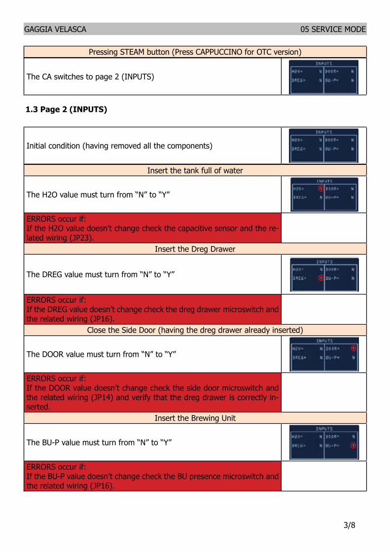
Test Mode INTELIA EVO V2 AMF
Filename Intelia_EVO2_AMF_TestMode_V05
50 G Divella 12062015 412 revNum Author Verified Approved SaveDate PPP
12 Page 1 (KEYB) Initial condition no button pressed
Press all the buttons from Ndeg1 till Ndeg9Whenever a button is pressed the ldquoONrdquo word appears near the related button number Pressing button Ndeg1 the backlight color switches from WHITE to REDPressing button Ndeg2 the backlight color switches from WHITE to PINK Pressing button Ndeg7 turns the STANDBY LED on To test button Ndeg4 it must be pressed just one time because it causes the CA to navigate to the next page
In case two or more buttons are pressed at the same time the display shows the expression ldquoTWO BTNrdquo This could be a useful warning if the keyboard is not working properly
ERRORS occur if ldquoONrdquo word does not appear or stays fixed on screen In this case itrsquos necessary to check the communication flat cable connected between the keyboard and the CPU-Power board Should not on the other hand change the display color check the JP5 cable
Pressing STEAM button The CA switches to page 2 (INPUTS)
Test Mode INTELIA EVO V2 AMF Filename
Intelia_EVO2_AMF_TestMode_V05
50 G Divella 12062015 512 revNum Author Verified Approved SaveDate PPP
13 Page 2 (INPUTS) Initial condition (having removed all the components)
Insert the tank full of waterThe H2O value must turn from ldquoNrdquo to ldquoYrdquo
ERRORS occur if If the H2O value doesnrsquot change check the capacitive sensor and the related wiring (JP23)
Insert the Dreg DrawerThe DREG value must turn from ldquoNrdquo to ldquoYrdquo
ERRORS occur if If the DREG value doesnrsquot change check the dreg drawer microswitch and the related wiring (JP16)
Close the Side Door (having the dreg drawer already inserted) The DOOR value must turn from ldquoNrdquo to ldquoYrdquo
ERRORS occur if If the DOOR value doesnrsquot change check the side door microswitch and the related wiring (JP14) and verify that the dreg drawer is correctly inserted
Test Mode INTELIA EVO V2 AMF Filename
Intelia_EVO2_AMF_TestMode_V05
50 G Divella 12062015 512 revNum Author Verified Approved SaveDate PPP
13 Page 2 (INPUTS) Initial condition (having removed all the components)
Insert the tank full of waterThe H2O value must turn from ldquoNrdquo to ldquoYrdquo
ERRORS occur if If the H2O value doesnrsquot change check the capacitive sensor and the related wiring (JP23)
Insert the Dreg DrawerThe DREG value must turn from ldquoNrdquo to ldquoYrdquo
ERRORS occur if If the DREG value doesnrsquot change check the dreg drawer microswitch and the related wiring (JP16)
Close the Side Door (having the dreg drawer already inserted) The DOOR value must turn from ldquoNrdquo to ldquoYrdquo
ERRORS occur if If the DOOR value doesnrsquot change check the side door microswitch and the related wiring (JP14) and verify that the dreg drawer is correctly inserted Test Mode INTELIA EVO V2 AMF
Filename Intelia_EVO2_AMF_TestMode_V05
50 G Divella 12062015 612 revNum Author Verified Approved SaveDate PPP
Insert the Brewing Unit The BU-P value must turn from ldquoNrdquo to ldquoYrdquo
ERRORS occur if If the BU-P value doesnrsquot change check the BU presence microswitch and the related wiring (JP16)
Test Mode INTELIA EVO V2 AMF
Filename Intelia_EVO2_AMF_TestMode_V05
50 G Divella 12062015 412 revNum Author Verified Approved SaveDate PPP
12 Page 1 (KEYB) Initial condition no button pressed
Press all the buttons from Ndeg1 till Ndeg9Whenever a button is pressed the ldquoONrdquo word appears near the related button number Pressing button Ndeg1 the backlight color switches from WHITE to REDPressing button Ndeg2 the backlight color switches from WHITE to PINK Pressing button Ndeg7 turns the STANDBY LED on To test button Ndeg4 it must be pressed just one time because it causes the CA to navigate to the next page
In case two or more buttons are pressed at the same time the display shows the expression ldquoTWO BTNrdquo This could be a useful warning if the keyboard is not working properly
ERRORS occur if ldquoONrdquo word does not appear or stays fixed on screen In this case itrsquos necessary to check the communication flat cable connected between the keyboard and the CPU-Power board Should not on the other hand change the display color check the JP5 cable
Pressing STEAM button The CA switches to page 2 (INPUTS)
GAGGIA VELASCA 05 SERVICE MODE
38
13 Page 2 (INPUTS)
Insert the tank full of water
The H2O value must turn from ldquoNrdquo to ldquoYrdquo
ERRORS occur ifIf the H2O value doesnrsquot change check the capacitive sensor and the re-lated wiring (JP23)
Insert the Dreg Drawer
The DREG value must turn from ldquoNrdquo to ldquoYrdquo
ERRORS occur ifIf the DREG value doesnrsquot change check the dreg drawer microswitch and the related wiring (JP16)
Close the Side Door (having the dreg drawer already inserted)
The DOOR value must turn from ldquoNrdquo to ldquoYrdquo
ERRORS occur ifIf the DOOR value doesnrsquot change check the side door microswitch and the related wiring (JP14) and verify that the dreg drawer is correctly in-serted
Insert the Brewing Unit
The BU-P value must turn from ldquoNrdquo to ldquoYrdquo
ERRORS occur ifIf the BU-P value doesnrsquot change check the BU presence microswitch and the related wiring (JP16)
Initial condition (having removed all the components)
The CA switches to page 2 (INPUTS)
Pressing STEAM button (Press CAPPUCCINO for OTC version)
Test Mode INTELIA EVO V2 AMF Filename
Intelia_EVO2_AMF_TestMode_V05
50 G Divella 12062015 712 revNum Author Verified Approved SaveDate PPP
14 Page 3 (BU)
Initial condition
Press the ESPRESSO button to conduct the BU to the Work position When the BU reaches the work position the value WORK turns from ldquoNrdquo to ldquoYrdquo The absorbed BU current must be less than 200mA if the BU is not inserted and less than 300mA if the BU is inserted
ERRORS occur if The WORK value stays fixed on ldquoNrdquo while the backlight turns RED from WHITE in this case check the microswitch the BU engine (could be blocked) and finally the JP16 and JP14 wirings
ERROR (BU not inserted) If the absorbed current is more than 200 mA the display backlight turns red In this case check the gears of the engine and its standing in the housing
ERROR (BU inserted)If the absorbed current is more than 300 mA the display backlight turns red In this case check the gears of the engine and its standing in the housing
Test Mode INTELIA EVO V2 AMF Filename
Intelia_EVO2_AMF_TestMode_V05
50 G Divella 12062015 712 revNum Author Verified Approved SaveDate PPP
14 Page 3 (BU)
Initial condition
Press the ESPRESSO button to conduct the BU to the Work position When the BU reaches the work position the value WORK turns from ldquoNrdquo to ldquoYrdquo The absorbed BU current must be less than 200mA if the BU is not inserted and less than 300mA if the BU is inserted
ERRORS occur if The WORK value stays fixed on ldquoNrdquo while the backlight turns RED from WHITE in this case check the microswitch the BU engine (could be blocked) and finally the JP16 and JP14 wirings
ERROR (BU not inserted) If the absorbed current is more than 200 mA the display backlight turns red In this case check the gears of the engine and its standing in the housing
ERROR (BU inserted)If the absorbed current is more than 300 mA the display backlight turns red In this case check the gears of the engine and its standing in the housing
Test Mode INTELIA EVO V2 AMF Filename
Intelia_EVO2_AMF_TestMode_V05
50 G Divella 12062015 712 revNum Author Verified Approved SaveDate PPP
14 Page 3 (BU)
Initial condition
Press the ESPRESSO button to conduct the BU to the Work position When the BU reaches the work position the value WORK turns from ldquoNrdquo to ldquoYrdquo The absorbed BU current must be less than 200mA if the BU is not inserted and less than 300mA if the BU is inserted
ERRORS occur if The WORK value stays fixed on ldquoNrdquo while the backlight turns RED from WHITE in this case check the microswitch the BU engine (could be blocked) and finally the JP16 and JP14 wirings
ERROR (BU not inserted) If the absorbed current is more than 200 mA the display backlight turns red In this case check the gears of the engine and its standing in the housing
ERROR (BU inserted)If the absorbed current is more than 300 mA the display backlight turns red In this case check the gears of the engine and its standing in the housing
Test Mode INTELIA EVO V2 AMF Filename
Intelia_EVO2_AMF_TestMode_V05
50 G Divella 12062015 712 revNum Author Verified Approved SaveDate PPP
14 Page 3 (BU)
Initial condition
Press the ESPRESSO button to conduct the BU to the Work position When the BU reaches the work position the value WORK turns from ldquoNrdquo to ldquoYrdquo The absorbed BU current must be less than 200mA if the BU is not inserted and less than 300mA if the BU is inserted
ERRORS occur if The WORK value stays fixed on ldquoNrdquo while the backlight turns RED from WHITE in this case check the microswitch the BU engine (could be blocked) and finally the JP16 and JP14 wirings
ERROR (BU not inserted) If the absorbed current is more than 200 mA the display backlight turns red In this case check the gears of the engine and its standing in the housing
ERROR (BU inserted)If the absorbed current is more than 300 mA the display backlight turns red In this case check the gears of the engine and its standing in the housing
Test Mode INTELIA EVO V2 AMF Filename
Intelia_EVO2_AMF_TestMode_V05
50 G Divella 12062015 712 revNum Author Verified Approved SaveDate PPP
14 Page 3 (BU)
Initial condition
Press the ESPRESSO button to conduct the BU to the Work position When the BU reaches the work position the value WORK turns from ldquoNrdquo to ldquoYrdquo The absorbed BU current must be less than 200mA if the BU is not inserted and less than 300mA if the BU is inserted
ERRORS occur if The WORK value stays fixed on ldquoNrdquo while the backlight turns RED from WHITE in this case check the microswitch the BU engine (could be blocked) and finally the JP16 and JP14 wirings
ERROR (BU not inserted) If the absorbed current is more than 200 mA the display backlight turns red In this case check the gears of the engine and its standing in the housing
ERROR (BU inserted)If the absorbed current is more than 300 mA the display backlight turns red In this case check the gears of the engine and its standing in the housing
Test Mode INTELIA EVO V2 AMF Filename
Intelia_EVO2_AMF_TestMode_V05
50 G Divella 12062015 812 revNum Author Verified Approved SaveDate PPP
Press the COFFEE button to move the BU towards the HOME position When the BU reaches the HOME position the HOME value changes from ldquoNrdquo to ldquoYrdquo The maximum absorbed current must be less than 200 mA (BU not inserted) 300 mA (BU inserted)
ERRORS occur if The HOME value stays fixed on ldquoNrdquo while the backlight turns RED from WHITE in this case check the microswitch the BU engine (could be blocked) and finally the JP16 and JP14 wirings
ERROR (BU not inserted) If the absorbed current is more than 200 mA the display backlight turns red In this case check the gears of the engine and its standing in the housing
ERROR (BU inserted)If the absorbed current is more than 300 mA the display backlight turns red In this case check the gears of the engine and its standing in the housing
Press the STEAM button The CA goes to the EVPUMP page (EV - PUMP)
Test Mode INTELIA EVO V2 AMF Filename
Intelia_EVO2_AMF_TestMode_V05
50 G Divella 12062015 812 revNum Author Verified Approved SaveDate PPP
Press the COFFEE button to move the BU towards the HOME position When the BU reaches the HOME position the HOME value changes from ldquoNrdquo to ldquoYrdquo The maximum absorbed current must be less than 200 mA (BU not inserted) 300 mA (BU inserted)
ERRORS occur if The HOME value stays fixed on ldquoNrdquo while the backlight turns RED from WHITE in this case check the microswitch the BU engine (could be blocked) and finally the JP16 and JP14 wirings
ERROR (BU not inserted) If the absorbed current is more than 200 mA the display backlight turns red In this case check the gears of the engine and its standing in the housing
ERROR (BU inserted)If the absorbed current is more than 300 mA the display backlight turns red In this case check the gears of the engine and its standing in the housing
Press the STEAM button The CA goes to the EVPUMP page (EV - PUMP)
Test Mode INTELIA EVO V2 AMF Filename
Intelia_EVO2_AMF_TestMode_V05
50 G Divella 12062015 812 revNum Author Verified Approved SaveDate PPP
Press the COFFEE button to move the BU towards the HOME position When the BU reaches the HOME position the HOME value changes from ldquoNrdquo to ldquoYrdquo The maximum absorbed current must be less than 200 mA (BU not inserted) 300 mA (BU inserted)
ERRORS occur if The HOME value stays fixed on ldquoNrdquo while the backlight turns RED from WHITE in this case check the microswitch the BU engine (could be blocked) and finally the JP16 and JP14 wirings
ERROR (BU not inserted) If the absorbed current is more than 200 mA the display backlight turns red In this case check the gears of the engine and its standing in the housing
ERROR (BU inserted)If the absorbed current is more than 300 mA the display backlight turns red In this case check the gears of the engine and its standing in the housing
Press the STEAM button The CA goes to the EVPUMP page (EV - PUMP)
Test Mode INTELIA EVO V2 AMF Filename
Intelia_EVO2_AMF_TestMode_V05
50 G Divella 12062015 812 revNum Author Verified Approved SaveDate PPP
Press the COFFEE button to move the BU towards the HOME position When the BU reaches the HOME position the HOME value changes from ldquoNrdquo to ldquoYrdquo The maximum absorbed current must be less than 200 mA (BU not inserted) 300 mA (BU inserted)
ERRORS occur if The HOME value stays fixed on ldquoNrdquo while the backlight turns RED from WHITE in this case check the microswitch the BU engine (could be blocked) and finally the JP16 and JP14 wirings
ERROR (BU not inserted) If the absorbed current is more than 200 mA the display backlight turns red In this case check the gears of the engine and its standing in the housing
ERROR (BU inserted)If the absorbed current is more than 300 mA the display backlight turns red In this case check the gears of the engine and its standing in the housing
Press the STEAM button The CA goes to the EVPUMP page (EV - PUMP)
Test Mode INTELIA EVO V2 AMF Filename
Intelia_EVO2_AMF_TestMode_V05
50 G Divella 12062015 812 revNum Author Verified Approved SaveDate PPP
Press the COFFEE button to move the BU towards the HOME position When the BU reaches the HOME position the HOME value changes from ldquoNrdquo to ldquoYrdquo The maximum absorbed current must be less than 200 mA (BU not inserted) 300 mA (BU inserted)
ERRORS occur if The HOME value stays fixed on ldquoNrdquo while the backlight turns RED from WHITE in this case check the microswitch the BU engine (could be blocked) and finally the JP16 and JP14 wirings
ERROR (BU not inserted) If the absorbed current is more than 200 mA the display backlight turns red In this case check the gears of the engine and its standing in the housing
ERROR (BU inserted)If the absorbed current is more than 300 mA the display backlight turns red In this case check the gears of the engine and its standing in the housing
Press the STEAM button The CA goes to the EVPUMP page (EV - PUMP)
GAGGIA VELASCA 05 SERVICE MODE
48
14 Page 3 (BU)
Press the ESPRESSO button to conduct the BU to the Work position
When the BU reaches the work position the value WORK turns from ldquoNrdquo to ldquoYrdquo The absorbed BU current must be less than 200mA if the BU is not inserted and less than 300mA if the BU is inserted
ERRORS occur ifThe WORK value stays fixed on ldquoNrdquo while the backlight turns RED from WHITE in this case check the microswitch the BU engine (could be blocked) and finally the JP16 and JP14 wiringsERROR (BU not inserted)If the absorbed current is more than 200 mA the display backlight turns red In this case check the gears of the engine and its standing in the housingERROR (BU inserted)If the absorbed current is more than 300 mA the display backlight turns red In this case check the gears of the engine and its standing in the housing
Press the COFFEE button to move the BU towards the HOME position
When the BU reaches the HOME position the HOME value changes from ldquoNrdquo to ldquoYrdquo The maximum absorbed current must be less than 200 mA (BU not inserted) 300 mA (BU inserted)
ERRORS occur ifThe HOME value stays fixed on ldquoNrdquo while the backlight turns RED from WHITE in this case check the microswitch the BU engine (could be blocked) and finally the JP16 and JP14 wiringsERROR (BU not inserted)If the absorbed current is more than 200 mA the display backlight turns red In this case check the gears of the engine and its standing in the housingERROR (BU inserted)If the absorbed current is more than 300 mA the display backlight turns red In this case check the gears of the engine and its standing in the housing
Press the STEAM button (Press CAPPUCCINO for OTC version)
The CA goes to the EVPUMP page (EV - PUMP)
Initial condition
Test Mode INTELIA EVO V2 AMF Filename
Intelia_EVO2_AMF_TestMode_V05
50 G Divella 12062015 912 revNum Author Verified Approved SaveDate PPP
15 Page 4 (EV - PUMP)
Should this page been shown it means either the dreg drawer is not correctly inserted or the side door not closed Only solving both these issues it would be possible to come out from this screen
Press the ESPRESSO button to activate the 2-ways Electrovalve (closed by default) The Electrovalve is activated so the EV1 value turns from ldquoOFFrdquo to ldquoONrdquo
Press the HOT WATER button to activate the PumpThe water now flows out from the spout causing the update of the IMP value with the number of flowmeter impulses The LH value must stay within 10lh and 18 lh
ERROR If the number of impulses remains 0 and the display backlight turns red it means that therersquos an error in the hydraulic circuit If water comes out from the spout it means that therersquos an error in the flowmeter or in its wiring to the CPUPOWER (JP5) if on the other hand no water comes out itrsquos necessary to check the pump or the hydraulic circuit or the pump wiring (JP24)
Press the STEAM WATER button The CA shows the HeaterGrinder page (Heater-Grinder)
16 Page5 (Heater-Grinder)
Test Mode INTELIA EVO V2 AMF Filename
Intelia_EVO2_AMF_TestMode_V05
50 G Divella 12062015 912 revNum Author Verified Approved SaveDate PPP
15 Page 4 (EV - PUMP)
Should this page been shown it means either the dreg drawer is not correctly inserted or the side door not closed Only solving both these issues it would be possible to come out from this screen
Press the ESPRESSO button to activate the 2-ways Electrovalve (closed by default) The Electrovalve is activated so the EV1 value turns from ldquoOFFrdquo to ldquoONrdquo
Press the HOT WATER button to activate the PumpThe water now flows out from the spout causing the update of the IMP value with the number of flowmeter impulses The LH value must stay within 10lh and 18 lh
ERROR If the number of impulses remains 0 and the display backlight turns red it means that therersquos an error in the hydraulic circuit If water comes out from the spout it means that therersquos an error in the flowmeter or in its wiring to the CPUPOWER (JP5) if on the other hand no water comes out itrsquos necessary to check the pump or the hydraulic circuit or the pump wiring (JP24)
Press the STEAM WATER button The CA shows the HeaterGrinder page (Heater-Grinder)
16 Page5 (Heater-Grinder)
Test Mode INTELIA EVO V2 AMF Filename
Intelia_EVO2_AMF_TestMode_V05
50 G Divella 12062015 912 revNum Author Verified Approved SaveDate PPP
15 Page 4 (EV - PUMP)
Should this page been shown it means either the dreg drawer is not correctly inserted or the side door not closed Only solving both these issues it would be possible to come out from this screen
Press the ESPRESSO button to activate the 2-ways Electrovalve (closed by default) The Electrovalve is activated so the EV1 value turns from ldquoOFFrdquo to ldquoONrdquo
Press the HOT WATER button to activate the PumpThe water now flows out from the spout causing the update of the IMP value with the number of flowmeter impulses The LH value must stay within 10lh and 18 lh
ERROR If the number of impulses remains 0 and the display backlight turns red it means that therersquos an error in the hydraulic circuit If water comes out from the spout it means that therersquos an error in the flowmeter or in its wiring to the CPUPOWER (JP5) if on the other hand no water comes out itrsquos necessary to check the pump or the hydraulic circuit or the pump wiring (JP24)
Press the STEAM WATER button The CA shows the HeaterGrinder page (Heater-Grinder)
16 Page5 (Heater-Grinder)
Test Mode INTELIA EVO V2 AMF Filename
Intelia_EVO2_AMF_TestMode_V05
50 G Divella 12062015 912 revNum Author Verified Approved SaveDate PPP
15 Page 4 (EV - PUMP)
Should this page been shown it means either the dreg drawer is not correctly inserted or the side door not closed Only solving both these issues it would be possible to come out from this screen
Press the ESPRESSO button to activate the 2-ways Electrovalve (closed by default) The Electrovalve is activated so the EV1 value turns from ldquoOFFrdquo to ldquoONrdquo
Press the HOT WATER button to activate the PumpThe water now flows out from the spout causing the update of the IMP value with the number of flowmeter impulses The LH value must stay within 10lh and 18 lh
ERROR If the number of impulses remains 0 and the display backlight turns red it means that therersquos an error in the hydraulic circuit If water comes out from the spout it means that therersquos an error in the flowmeter or in its wiring to the CPUPOWER (JP5) if on the other hand no water comes out itrsquos necessary to check the pump or the hydraulic circuit or the pump wiring (JP24)
Press the STEAM WATER button The CA shows the HeaterGrinder page (Heater-Grinder)
16 Page5 (Heater-Grinder)
Test Mode INTELIA EVO V2 AMF Filename
Intelia_EVO2_AMF_TestMode_V05
50 G Divella 12062015 912 revNum Author Verified Approved SaveDate PPP
15 Page 4 (EV - PUMP)
Should this page been shown it means either the dreg drawer is not correctly inserted or the side door not closed Only solving both these issues it would be possible to come out from this screen
Press the ESPRESSO button to activate the 2-ways Electrovalve (closed by default) The Electrovalve is activated so the EV1 value turns from ldquoOFFrdquo to ldquoONrdquo
Press the HOT WATER button to activate the PumpThe water now flows out from the spout causing the update of the IMP value with the number of flowmeter impulses The LH value must stay within 10lh and 18 lh
ERROR If the number of impulses remains 0 and the display backlight turns red it means that therersquos an error in the hydraulic circuit If water comes out from the spout it means that therersquos an error in the flowmeter or in its wiring to the CPUPOWER (JP5) if on the other hand no water comes out itrsquos necessary to check the pump or the hydraulic circuit or the pump wiring (JP24)
Press the STEAM WATER button The CA shows the HeaterGrinder page (Heater-Grinder)
16 Page5 (Heater-Grinder)
Test Mode INTELIA EVO V2 AMF Filename
Intelia_EVO2_AMF_TestMode_V05
50 G Divella 12062015 912 revNum Author Verified Approved SaveDate PPP
15 Page 4 (EV - PUMP)
Should this page been shown it means either the dreg drawer is not correctly inserted or the side door not closed Only solving both these issues it would be possible to come out from this screen
Press the ESPRESSO button to activate the 2-ways Electrovalve (closed by default) The Electrovalve is activated so the EV1 value turns from ldquoOFFrdquo to ldquoONrdquo
Press the HOT WATER button to activate the PumpThe water now flows out from the spout causing the update of the IMP value with the number of flowmeter impulses The LH value must stay within 10lh and 18 lh
ERROR If the number of impulses remains 0 and the display backlight turns red it means that therersquos an error in the hydraulic circuit If water comes out from the spout it means that therersquos an error in the flowmeter or in its wiring to the CPUPOWER (JP5) if on the other hand no water comes out itrsquos necessary to check the pump or the hydraulic circuit or the pump wiring (JP24)
Press the STEAM WATER button The CA shows the HeaterGrinder page (Heater-Grinder)
16 Page5 (Heater-Grinder)
Test Mode INTELIA EVO V2 AMF Filename
Intelia_EVO2_AMF_TestMode_V05
50 G Divella 12062015 1012 revNum Author Verified Approved SaveDate PPP
Initial condition
Press the HOT WATER button to activate the GrinderThe coffee grinder starts milling for 5000 ms if the user doesnrsquot release the button before In this case the activation time is shown in the red-circled field of the picture
ERROR If this number keeps fixed at 0 the display turns red and the engine moves then there must be a fault in the grinder wiring (JP8) or in the grinder itself
Keep pressed STANDBY for 5 secs to reset grinder parameters Pressing button STANDBY for 5 secs resets grinder parameters
Test Mode INTELIA EVO V2 AMF Filename
Intelia_EVO2_AMF_TestMode_V05
50 G Divella 12062015 1012 revNum Author Verified Approved SaveDate PPP
Initial condition
Press the HOT WATER button to activate the GrinderThe coffee grinder starts milling for 5000 ms if the user doesnrsquot release the button before In this case the activation time is shown in the red-circled field of the picture
ERROR If this number keeps fixed at 0 the display turns red and the engine moves then there must be a fault in the grinder wiring (JP8) or in the grinder itself
Keep pressed STANDBY for 5 secs to reset grinder parameters Pressing button STANDBY for 5 secs resets grinder parameters
Test Mode INTELIA EVO V2 AMF Filename
Intelia_EVO2_AMF_TestMode_V05
50 G Divella 12062015 1012 revNum Author Verified Approved SaveDate PPP
Initial condition
Press the HOT WATER button to activate the GrinderThe coffee grinder starts milling for 5000 ms if the user doesnrsquot release the button before In this case the activation time is shown in the red-circled field of the picture
ERROR If this number keeps fixed at 0 the display turns red and the engine moves then there must be a fault in the grinder wiring (JP8) or in the grinder itself
Keep pressed STANDBY for 5 secs to reset grinder parameters Pressing button STANDBY for 5 secs resets grinder parameters
GAGGIA VELASCA 05 SERVICE MODE
58
15 Page 4 (EV - PUMP)
Press the ESPRESSO button to activate the 2-ways Electrovalve (closed by default)
The Electrovalve is activated so the EV1 value turns from ldquoOFFrdquo to ldquoONrdquo
Press the HOT WATER (Press MILK for OTC version) button to activate the Pump
The water now flows out from the spout causing the update of the IMP value with the number of flowmeter impulses The LH value must stay within 10lh and 18 lh
ERRORIf the number of impulses remains 0 and the display backlight turns red it means that therersquos an error in the hydraulic circuit If water comes out from the spout it means that therersquos an error in the flowmeter or in its wiring to the CPUPOWER (JP5) if on the other hand no water comes out itrsquos necessary to check the pump or the hydraulic circuit or the pump wiring (JP24)
Press the STEAM WATER button (Press CAPPUCCINO for OTC version)
The CA shows the HeaterGrinder page (Heater-Grinder)
Initial condition
Press the HOT WATER (Press MILK for OTC version) button to activate the Grinder
The coffee grinder starts milling for 5000 ms In this case the activation time is shown in the red-circled field of the picture
ERRORIf this number keeps fixed at 0or the grinder does not run the display turns red this means there must be a fault in the grinder wiring (JP8) or in the grinder itself or in the electronic board
Keep pressed STANDBY for 5 secs to reset grinder parameters
Pressing button STANDBY for 5 secs resets grinder parametersThis action is needed if the grinder has been replaced
Should this page been shown it means either the dreg drawer is not cor-rectly inserted or the side door not closed Only solving both these issues it would be possible to come out from this screen
16 Page 5 (Heater-Grinder)
Test Mode INTELIA EVO V2 AMF Filename
Intelia_EVO2_AMF_TestMode_V05
50 G Divella 12062015 1112 revNum Author Verified Approved SaveDate PPP
Heater Temperature monitoring The red-circled number shows the heater temperature in Celsius degrees
ERROR If inside the HEATER column appears the word ldquoSHORTrdquo then the NTC sensor is in a short-circuit state The display backlight turns RED from WHITE in this case the NTC wiring or the input CPUPOWER (JP13) must be checked
ERROR If inside the HEATER column appears the word ldquoOPENrdquo then the NTC sensor is disconnected The display backlight turns RED from WHITE In this case the connectivity of the NTC wiring to the CPUPOWER (JP13) must be checked
Press the COFFEE button to activate the heaterThe label switches from ldquoOFFrdquo to ldquoONrdquo and the number indicating the temperature starts to increase (and so the current absorbed by the CA on the power supply ndash ca 8 A 230V) For safety reasons it is possible to activate the heater keeping pressed the button for a maximum time of 5 seconds
Therersquos a further check on the temperature level should it rise over 120degC the display backlight turns pink and an alarm message appears In this scenario the heater is forced to stay turned off to avoid dangerous over-temperatures
ERROR If therersquos no temperature increasing the user must check the heater resistance its wiring to the CPUPOWER (JP19) and also the NTC wiring (JP13)
Press both the AROMA and the MENU buttons These values appear on the display
Grinding time applied during last mill Average of the low state duration of the current sensor
signal Threshold for the presenceabsence coffee detection
Test Mode INTELIA EVO V2 AMF Filename
Intelia_EVO2_AMF_TestMode_V05
50 G Divella 12062015 1112 revNum Author Verified Approved SaveDate PPP
Heater Temperature monitoring The red-circled number shows the heater temperature in Celsius degrees
ERROR If inside the HEATER column appears the word ldquoSHORTrdquo then the NTC sensor is in a short-circuit state The display backlight turns RED from WHITE in this case the NTC wiring or the input CPUPOWER (JP13) must be checked
ERROR If inside the HEATER column appears the word ldquoOPENrdquo then the NTC sensor is disconnected The display backlight turns RED from WHITE In this case the connectivity of the NTC wiring to the CPUPOWER (JP13) must be checked
Press the COFFEE button to activate the heaterThe label switches from ldquoOFFrdquo to ldquoONrdquo and the number indicating the temperature starts to increase (and so the current absorbed by the CA on the power supply ndash ca 8 A 230V) For safety reasons it is possible to activate the heater keeping pressed the button for a maximum time of 5 seconds
Therersquos a further check on the temperature level should it rise over 120degC the display backlight turns pink and an alarm message appears In this scenario the heater is forced to stay turned off to avoid dangerous over-temperatures
ERROR If therersquos no temperature increasing the user must check the heater resistance its wiring to the CPUPOWER (JP19) and also the NTC wiring (JP13)
Press both the AROMA and the MENU buttons These values appear on the display
Grinding time applied during last mill Average of the low state duration of the current sensor
signal Threshold for the presenceabsence coffee detection
Test Mode INTELIA EVO V2 AMF Filename
Intelia_EVO2_AMF_TestMode_V05
50 G Divella 12062015 1112 revNum Author Verified Approved SaveDate PPP
Heater Temperature monitoring The red-circled number shows the heater temperature in Celsius degrees
ERROR If inside the HEATER column appears the word ldquoSHORTrdquo then the NTC sensor is in a short-circuit state The display backlight turns RED from WHITE in this case the NTC wiring or the input CPUPOWER (JP13) must be checked
ERROR If inside the HEATER column appears the word ldquoOPENrdquo then the NTC sensor is disconnected The display backlight turns RED from WHITE In this case the connectivity of the NTC wiring to the CPUPOWER (JP13) must be checked
Press the COFFEE button to activate the heaterThe label switches from ldquoOFFrdquo to ldquoONrdquo and the number indicating the temperature starts to increase (and so the current absorbed by the CA on the power supply ndash ca 8 A 230V) For safety reasons it is possible to activate the heater keeping pressed the button for a maximum time of 5 seconds
Therersquos a further check on the temperature level should it rise over 120degC the display backlight turns pink and an alarm message appears In this scenario the heater is forced to stay turned off to avoid dangerous over-temperatures
ERROR If therersquos no temperature increasing the user must check the heater resistance its wiring to the CPUPOWER (JP19) and also the NTC wiring (JP13)
Press both the AROMA and the MENU buttons These values appear on the display
Grinding time applied during last mill Average of the low state duration of the current sensor
signal Threshold for the presenceabsence coffee detection
Test Mode INTELIA EVO V2 AMF Filename
Intelia_EVO2_AMF_TestMode_V05
50 G Divella 12062015 1112 revNum Author Verified Approved SaveDate PPP
Heater Temperature monitoring The red-circled number shows the heater temperature in Celsius degrees
ERROR If inside the HEATER column appears the word ldquoSHORTrdquo then the NTC sensor is in a short-circuit state The display backlight turns RED from WHITE in this case the NTC wiring or the input CPUPOWER (JP13) must be checked
ERROR If inside the HEATER column appears the word ldquoOPENrdquo then the NTC sensor is disconnected The display backlight turns RED from WHITE In this case the connectivity of the NTC wiring to the CPUPOWER (JP13) must be checked
Press the COFFEE button to activate the heaterThe label switches from ldquoOFFrdquo to ldquoONrdquo and the number indicating the temperature starts to increase (and so the current absorbed by the CA on the power supply ndash ca 8 A 230V) For safety reasons it is possible to activate the heater keeping pressed the button for a maximum time of 5 seconds
Therersquos a further check on the temperature level should it rise over 120degC the display backlight turns pink and an alarm message appears In this scenario the heater is forced to stay turned off to avoid dangerous over-temperatures
ERROR If therersquos no temperature increasing the user must check the heater resistance its wiring to the CPUPOWER (JP19) and also the NTC wiring (JP13)
Press both the AROMA and the MENU buttons These values appear on the display
Grinding time applied during last mill Average of the low state duration of the current sensor
signal Threshold for the presenceabsence coffee detection
Test Mode INTELIA EVO V2 AMF Filename
Intelia_EVO2_AMF_TestMode_V05
50 G Divella 12062015 1112 revNum Author Verified Approved SaveDate PPP
Heater Temperature monitoring The red-circled number shows the heater temperature in Celsius degrees
ERROR If inside the HEATER column appears the word ldquoSHORTrdquo then the NTC sensor is in a short-circuit state The display backlight turns RED from WHITE in this case the NTC wiring or the input CPUPOWER (JP13) must be checked
ERROR If inside the HEATER column appears the word ldquoOPENrdquo then the NTC sensor is disconnected The display backlight turns RED from WHITE In this case the connectivity of the NTC wiring to the CPUPOWER (JP13) must be checked
Press the COFFEE button to activate the heaterThe label switches from ldquoOFFrdquo to ldquoONrdquo and the number indicating the temperature starts to increase (and so the current absorbed by the CA on the power supply ndash ca 8 A 230V) For safety reasons it is possible to activate the heater keeping pressed the button for a maximum time of 5 seconds
Therersquos a further check on the temperature level should it rise over 120degC the display backlight turns pink and an alarm message appears In this scenario the heater is forced to stay turned off to avoid dangerous over-temperatures
ERROR If therersquos no temperature increasing the user must check the heater resistance its wiring to the CPUPOWER (JP19) and also the NTC wiring (JP13)
Press both the AROMA and the MENU buttons These values appear on the display
Grinding time applied during last mill Average of the low state duration of the current sensor
signal Threshold for the presenceabsence coffee detection
Test Mode INTELIA EVO V2 AMF Filename
Intelia_EVO2_AMF_TestMode_V05
50 G Divella 12062015 1112 revNum Author Verified Approved SaveDate PPP
Heater Temperature monitoring The red-circled number shows the heater temperature in Celsius degrees
ERROR If inside the HEATER column appears the word ldquoSHORTrdquo then the NTC sensor is in a short-circuit state The display backlight turns RED from WHITE in this case the NTC wiring or the input CPUPOWER (JP13) must be checked
ERROR If inside the HEATER column appears the word ldquoOPENrdquo then the NTC sensor is disconnected The display backlight turns RED from WHITE In this case the connectivity of the NTC wiring to the CPUPOWER (JP13) must be checked
Press the COFFEE button to activate the heaterThe label switches from ldquoOFFrdquo to ldquoONrdquo and the number indicating the temperature starts to increase (and so the current absorbed by the CA on the power supply ndash ca 8 A 230V) For safety reasons it is possible to activate the heater keeping pressed the button for a maximum time of 5 seconds
Therersquos a further check on the temperature level should it rise over 120degC the display backlight turns pink and an alarm message appears In this scenario the heater is forced to stay turned off to avoid dangerous over-temperatures
ERROR If therersquos no temperature increasing the user must check the heater resistance its wiring to the CPUPOWER (JP19) and also the NTC wiring (JP13)
Press both the AROMA and the MENU buttons These values appear on the display
Grinding time applied during last mill Average of the low state duration of the current sensor
signal Threshold for the presenceabsence coffee detection
Test Mode INTELIA EVO V2 AMF Filename
Intelia_EVO2_AMF_TestMode_V05
50 G Divella 12062015 1212 revNum Author Verified Approved SaveDate PPP
Press the STEAM button The CA shows the Autodoses page
17 Page 6 (Autodoses) The CA shows the AUTODOSES page with the time of milling for the different coffee aroma
Light Med Strong
Test Mode INTELIA EVO V2 AMF Filename
Intelia_EVO2_AMF_TestMode_V05
50 G Divella 12062015 1212 revNum Author Verified Approved SaveDate PPP
Press the STEAM button The CA shows the Autodoses page
17 Page 6 (Autodoses) The CA shows the AUTODOSES page with the time of milling for the different coffee aroma
Light Med Strong
GAGGIA VELASCA 05 SERVICE MODE
68
Heater Temperature monitoring
The red-circled number shows the heater temperature in Celsius degrees
ERRORIf inside the HEATER column appears the word ldquoSHORTrdquo then the NTC sensor is in a short-circuit state The display backlight turns RED from WHITE in this case the NTC wiring or the input CPUPOWER (JP13) must be checkedERRORIf inside the HEATER column appears the word ldquoOPENrdquo then the NTC sensor is disconnected The display backlight turns RED from WHITE In this case the connectivity of the NTC wiring to the CPUPOWER (JP13) must be checked
Press the COFFEE button to activate the heaterThe label switches from ldquoOFFrdquo to ldquoONrdquo and the number indicating the temperature starts to increase (and so the current absorbed by the CA on the power supply ndash ca 8 A 230V)For safety reasons it is possible to activate the heater keeping pressed the button for a maximum time of 5 secondsTherersquos a further check on the temperature level should it rise over 120degC the display backlight turns pink and an alarm message appears In this scenario the heater is forced to stay turned off to avoid dangerous over-temperatures
ERRORIf therersquos no temperature increasing the user must check the heater re-sistance its wiring to the CPUPOWER (JP19) and also the NTC wiring (JP13)
Press both the AROMA and the MENU(CMF-AMF version)SPECIALS(OTC version) buttonsThis page shows extended info Check of these number is not requestedFollowing values appear on the displaybull Grinding time applied during last millbull Average of the low state duration of the current sensor signalbull Threshold for the presenceabsence coffee detection
Press the STEAM button (Press CAPPUCCINO for OTC version)
The CA shows the Autodoses page
The CA shows the AUTODOSES page with the time of milling for the dif-ferent coffee aromabull Lightbull Medbull Strong
17 Page 6 (Autodoses)
Steam Out Intelia EVO 2 OTCAMF
Filename
Intelia_EVO2_Stea
m_Out_V03doc
03 G Divella 02072015 23
revNum Editor Verified By Approved By SaveDate PPP
Introduction
This document describes the Steam-Out process that is executed at the end of the production line for the CA
INTELIA EVO 2 OTCAMF It totally empties the heater from any residual water and resets some parameters
to the factory default values
1 Steam Out
To access Steam Out the user must press both LONG COFFEE and SPECIAL DRINKS (MENU for AMF)
buttons while connecting the CA to the power supply
When lit the CA will start the procedure turning PINK the display
backlight and showing ldquoONrdquo on the screen-
During the process the 2-ways Electrovalve will stay open causing
steam to be discharged from the spout (hot water wand for AMF
version)
Warning
If the dreg drawer is not correctly inserted or the side door open the
CA shows a RED screen with the advice ldquoCLOSE DOOR amp DREGSrdquo
At the end of the process the display will turn WHITE and show the
ldquoCOMPLETErdquo word on the screen The Electrovalve also will be
closed and the CA will be ready to be manually turned off
Steam Out Intelia EVO 2 OTCAMF
Filename
Intelia_EVO2_Stea
m_Out_V03doc
03 G Divella 02072015 23
revNum Editor Verified By Approved By SaveDate PPP
Introduction
This document describes the Steam-Out process that is executed at the end of the production line for the CA
INTELIA EVO 2 OTCAMF It totally empties the heater from any residual water and resets some parameters
to the factory default values
1 Steam Out
To access Steam Out the user must press both LONG COFFEE and SPECIAL DRINKS (MENU for AMF)
buttons while connecting the CA to the power supply
When lit the CA will start the procedure turning PINK the display
backlight and showing ldquoONrdquo on the screen-
During the process the 2-ways Electrovalve will stay open causing
steam to be discharged from the spout (hot water wand for AMF
version)
Warning
If the dreg drawer is not correctly inserted or the side door open the
CA shows a RED screen with the advice ldquoCLOSE DOOR amp DREGSrdquo
At the end of the process the display will turn WHITE and show the
ldquoCOMPLETErdquo word on the screen The Electrovalve also will be
closed and the CA will be ready to be manually turned off
Steam Out Intelia EVO 2 OTCAMF
Filename
Intelia_EVO2_Stea
m_Out_V03doc
03 G Divella 02072015 23
revNum Editor Verified By Approved By SaveDate PPP
Introduction
This document describes the Steam-Out process that is executed at the end of the production line for the CA
INTELIA EVO 2 OTCAMF It totally empties the heater from any residual water and resets some parameters
to the factory default values
1 Steam Out
To access Steam Out the user must press both LONG COFFEE and SPECIAL DRINKS (MENU for AMF)
buttons while connecting the CA to the power supply
When lit the CA will start the procedure turning PINK the display
backlight and showing ldquoONrdquo on the screen-
During the process the 2-ways Electrovalve will stay open causing
steam to be discharged from the spout (hot water wand for AMF
version)
Warning
If the dreg drawer is not correctly inserted or the side door open the
CA shows a RED screen with the advice ldquoCLOSE DOOR amp DREGSrdquo
At the end of the process the display will turn WHITE and show the
ldquoCOMPLETErdquo word on the screen The Electrovalve also will be
closed and the CA will be ready to be manually turned off
GAGGIA VELASCA 05 SERVICE MODE
78
52 Steam Out
Not mandatory but if necessary before executing the steam out procedure descale the machine taking care to remouve the Aquaclean filter from the applianceIn case the filter on the machine is active (or itrsquos in the machine) provide the consumer with a new one
IntroductionThis document describes the Steam-Out process that is executed at the end of the production line for the CA GAGGIA VELASCA It totally empties the heater from any residual water and resets some parameters to the factory default values
Steam OutTo access Steam Out the user must press both LONG COFFEE and SPECIAL DRINKS (MENU for AMF)buttons while connecting the CA to the power supply
The Steam-Out resets these parameters to their factory values
OTC version product quantitiesShort Coffee (Espresso) Long Coffee Coffee Intense Coffee in cappuccino Milk in cappuccino Froth Milk brewing time
AMF version product quantitiesShort Coffee (Espresso) Long Coffee
Longevity Filter setupFilter Startup Quantity Filter Counter Filter Remaining Autonomy Filter Installation proposal at start
CA SettingsPre-infusion
impulses = 137impulses = 330impulses = 265 (brewed within two mill-brew cycles)impulses = 165seconds = 34seconds = 34
impulses = 137impulses = 330
5000 impulses080ON
Seconds = 25
When lit the CA will start the procedure turning PINK the display back-light and showing ldquoONrdquo on the screen-During the process the 2-ways Electrovalve will stay open causing steam to be discharged from the spout (hot water wand for AMF version)
WarningIf the dreg drawer is not correctly inserted or the side door open the CA shows a RED screen with the advice ldquoCLOSE DOOR amp DREGSrdquo
At the end of the process the display will turn WHITE and show the ldquoCOMPLETErdquo word on the screen The Electrovalve also will be closed and the CA will be ready to be manually turned off
GAGGIA VELASCA 05 SERVICE MODE
88
CODE Description NOTES01 Grinder fail
02 The grinder is disconnected (Only coffee grinder without electronic sensor)
03 Bu movement toward WORK fail04 Bu movement toward HOME fail05 Water circuit fail10 NTC short circuit fail11 NTC open circuit fail14 Heater over-temperature fail15 Heater time-out fail19 Zero-Crossing fail
Aroma Standby Time Alarm Refill Grounds counter Alarm Dreg Drawer Brewing Group Loaded Coffee Duct empty GrinderAroma 1 Time GrinderAroma 2 Time GrinderAroma 3 Time
() ATTENTION As a consequence of this reset the machine will grind for a longer time at first coffee product after Steam Out For this reason after Steam out the machine should be completely cleaned from all beans and all coffee powder residuals in the grinder
Medium (3 beans selected)15 minutesONReset to zeroOFFOFFYES ()550070007500
53 Error Codes for Out of Order alarm
54 Saeco Service Center - Quick Start Guide
Saeco Service Center ndash Quick Start GuidePress the icon to view the documentTo open the attached document is necessary to save the service manual on your PC
Saeco Service Center (SSC) is a tool with which you can re-program the machine and check the diagnostic of the sameYou can download the software from the following link httplogsavelogtronicscomSSC2publishhtmIn support of this tool it is essential to order the Saeco Programming DeviceCod 20000490 ldquoKIT PROGRAMMER SERKIT SSC2rdquoThis kit includes the programmer and cables helpful All details related to the registration and operation are explained in the enclosed Quick start guide(QSG)

Test Mode INTELIA EVO V2 AMF Filename
Intelia_EVO2_AMF_TestMode_V05
50 G Divella 12062015 712 revNum Author Verified Approved SaveDate PPP
14 Page 3 (BU)
Initial condition
Press the ESPRESSO button to conduct the BU to the Work position When the BU reaches the work position the value WORK turns from ldquoNrdquo to ldquoYrdquo The absorbed BU current must be less than 200mA if the BU is not inserted and less than 300mA if the BU is inserted
ERRORS occur if The WORK value stays fixed on ldquoNrdquo while the backlight turns RED from WHITE in this case check the microswitch the BU engine (could be blocked) and finally the JP16 and JP14 wirings
ERROR (BU not inserted) If the absorbed current is more than 200 mA the display backlight turns red In this case check the gears of the engine and its standing in the housing
ERROR (BU inserted)If the absorbed current is more than 300 mA the display backlight turns red In this case check the gears of the engine and its standing in the housing
Test Mode INTELIA EVO V2 AMF Filename
Intelia_EVO2_AMF_TestMode_V05
50 G Divella 12062015 812 revNum Author Verified Approved SaveDate PPP
Press the COFFEE button to move the BU towards the HOME position When the BU reaches the HOME position the HOME value changes from ldquoNrdquo to ldquoYrdquo The maximum absorbed current must be less than 200 mA (BU not inserted) 300 mA (BU inserted)
ERRORS occur if The HOME value stays fixed on ldquoNrdquo while the backlight turns RED from WHITE in this case check the microswitch the BU engine (could be blocked) and finally the JP16 and JP14 wirings
ERROR (BU not inserted) If the absorbed current is more than 200 mA the display backlight turns red In this case check the gears of the engine and its standing in the housing
ERROR (BU inserted)If the absorbed current is more than 300 mA the display backlight turns red In this case check the gears of the engine and its standing in the housing
Press the STEAM button The CA goes to the EVPUMP page (EV - PUMP)
GAGGIA VELASCA 05 SERVICE MODE
48
14 Page 3 (BU)
Press the ESPRESSO button to conduct the BU to the Work position
When the BU reaches the work position the value WORK turns from ldquoNrdquo to ldquoYrdquo The absorbed BU current must be less than 200mA if the BU is not inserted and less than 300mA if the BU is inserted
ERRORS occur ifThe WORK value stays fixed on ldquoNrdquo while the backlight turns RED from WHITE in this case check the microswitch the BU engine (could be blocked) and finally the JP16 and JP14 wiringsERROR (BU not inserted)If the absorbed current is more than 200 mA the display backlight turns red In this case check the gears of the engine and its standing in the housingERROR (BU inserted)If the absorbed current is more than 300 mA the display backlight turns red In this case check the gears of the engine and its standing in the housing
Press the COFFEE button to move the BU towards the HOME position
When the BU reaches the HOME position the HOME value changes from ldquoNrdquo to ldquoYrdquo The maximum absorbed current must be less than 200 mA (BU not inserted) 300 mA (BU inserted)
ERRORS occur ifThe HOME value stays fixed on ldquoNrdquo while the backlight turns RED from WHITE in this case check the microswitch the BU engine (could be blocked) and finally the JP16 and JP14 wiringsERROR (BU not inserted)If the absorbed current is more than 200 mA the display backlight turns red In this case check the gears of the engine and its standing in the housingERROR (BU inserted)If the absorbed current is more than 300 mA the display backlight turns red In this case check the gears of the engine and its standing in the housing
Press the STEAM button (Press CAPPUCCINO for OTC version)
The CA goes to the EVPUMP page (EV - PUMP)
Initial condition
Test Mode INTELIA EVO V2 AMF Filename
Intelia_EVO2_AMF_TestMode_V05
50 G Divella 12062015 912 revNum Author Verified Approved SaveDate PPP
15 Page 4 (EV - PUMP)
Should this page been shown it means either the dreg drawer is not correctly inserted or the side door not closed Only solving both these issues it would be possible to come out from this screen
Press the ESPRESSO button to activate the 2-ways Electrovalve (closed by default) The Electrovalve is activated so the EV1 value turns from ldquoOFFrdquo to ldquoONrdquo
Press the HOT WATER button to activate the PumpThe water now flows out from the spout causing the update of the IMP value with the number of flowmeter impulses The LH value must stay within 10lh and 18 lh
ERROR If the number of impulses remains 0 and the display backlight turns red it means that therersquos an error in the hydraulic circuit If water comes out from the spout it means that therersquos an error in the flowmeter or in its wiring to the CPUPOWER (JP5) if on the other hand no water comes out itrsquos necessary to check the pump or the hydraulic circuit or the pump wiring (JP24)
Press the STEAM WATER button The CA shows the HeaterGrinder page (Heater-Grinder)
16 Page5 (Heater-Grinder)
Test Mode INTELIA EVO V2 AMF Filename
Intelia_EVO2_AMF_TestMode_V05
50 G Divella 12062015 912 revNum Author Verified Approved SaveDate PPP
15 Page 4 (EV - PUMP)
Should this page been shown it means either the dreg drawer is not correctly inserted or the side door not closed Only solving both these issues it would be possible to come out from this screen
Press the ESPRESSO button to activate the 2-ways Electrovalve (closed by default) The Electrovalve is activated so the EV1 value turns from ldquoOFFrdquo to ldquoONrdquo
Press the HOT WATER button to activate the PumpThe water now flows out from the spout causing the update of the IMP value with the number of flowmeter impulses The LH value must stay within 10lh and 18 lh
ERROR If the number of impulses remains 0 and the display backlight turns red it means that therersquos an error in the hydraulic circuit If water comes out from the spout it means that therersquos an error in the flowmeter or in its wiring to the CPUPOWER (JP5) if on the other hand no water comes out itrsquos necessary to check the pump or the hydraulic circuit or the pump wiring (JP24)
Press the STEAM WATER button The CA shows the HeaterGrinder page (Heater-Grinder)
16 Page5 (Heater-Grinder)
Test Mode INTELIA EVO V2 AMF Filename
Intelia_EVO2_AMF_TestMode_V05
50 G Divella 12062015 912 revNum Author Verified Approved SaveDate PPP
15 Page 4 (EV - PUMP)
Should this page been shown it means either the dreg drawer is not correctly inserted or the side door not closed Only solving both these issues it would be possible to come out from this screen
Press the ESPRESSO button to activate the 2-ways Electrovalve (closed by default) The Electrovalve is activated so the EV1 value turns from ldquoOFFrdquo to ldquoONrdquo
Press the HOT WATER button to activate the PumpThe water now flows out from the spout causing the update of the IMP value with the number of flowmeter impulses The LH value must stay within 10lh and 18 lh
ERROR If the number of impulses remains 0 and the display backlight turns red it means that therersquos an error in the hydraulic circuit If water comes out from the spout it means that therersquos an error in the flowmeter or in its wiring to the CPUPOWER (JP5) if on the other hand no water comes out itrsquos necessary to check the pump or the hydraulic circuit or the pump wiring (JP24)
Press the STEAM WATER button The CA shows the HeaterGrinder page (Heater-Grinder)
16 Page5 (Heater-Grinder)
Test Mode INTELIA EVO V2 AMF Filename
Intelia_EVO2_AMF_TestMode_V05
50 G Divella 12062015 912 revNum Author Verified Approved SaveDate PPP
15 Page 4 (EV - PUMP)
Should this page been shown it means either the dreg drawer is not correctly inserted or the side door not closed Only solving both these issues it would be possible to come out from this screen
Press the ESPRESSO button to activate the 2-ways Electrovalve (closed by default) The Electrovalve is activated so the EV1 value turns from ldquoOFFrdquo to ldquoONrdquo
Press the HOT WATER button to activate the PumpThe water now flows out from the spout causing the update of the IMP value with the number of flowmeter impulses The LH value must stay within 10lh and 18 lh
ERROR If the number of impulses remains 0 and the display backlight turns red it means that therersquos an error in the hydraulic circuit If water comes out from the spout it means that therersquos an error in the flowmeter or in its wiring to the CPUPOWER (JP5) if on the other hand no water comes out itrsquos necessary to check the pump or the hydraulic circuit or the pump wiring (JP24)
Press the STEAM WATER button The CA shows the HeaterGrinder page (Heater-Grinder)
16 Page5 (Heater-Grinder)
Test Mode INTELIA EVO V2 AMF Filename
Intelia_EVO2_AMF_TestMode_V05
50 G Divella 12062015 912 revNum Author Verified Approved SaveDate PPP
15 Page 4 (EV - PUMP)
Should this page been shown it means either the dreg drawer is not correctly inserted or the side door not closed Only solving both these issues it would be possible to come out from this screen
Press the ESPRESSO button to activate the 2-ways Electrovalve (closed by default) The Electrovalve is activated so the EV1 value turns from ldquoOFFrdquo to ldquoONrdquo
Press the HOT WATER button to activate the PumpThe water now flows out from the spout causing the update of the IMP value with the number of flowmeter impulses The LH value must stay within 10lh and 18 lh
ERROR If the number of impulses remains 0 and the display backlight turns red it means that therersquos an error in the hydraulic circuit If water comes out from the spout it means that therersquos an error in the flowmeter or in its wiring to the CPUPOWER (JP5) if on the other hand no water comes out itrsquos necessary to check the pump or the hydraulic circuit or the pump wiring (JP24)
Press the STEAM WATER button The CA shows the HeaterGrinder page (Heater-Grinder)
16 Page5 (Heater-Grinder)
Test Mode INTELIA EVO V2 AMF Filename
Intelia_EVO2_AMF_TestMode_V05
50 G Divella 12062015 912 revNum Author Verified Approved SaveDate PPP
15 Page 4 (EV - PUMP)
Should this page been shown it means either the dreg drawer is not correctly inserted or the side door not closed Only solving both these issues it would be possible to come out from this screen
Press the ESPRESSO button to activate the 2-ways Electrovalve (closed by default) The Electrovalve is activated so the EV1 value turns from ldquoOFFrdquo to ldquoONrdquo
Press the HOT WATER button to activate the PumpThe water now flows out from the spout causing the update of the IMP value with the number of flowmeter impulses The LH value must stay within 10lh and 18 lh
ERROR If the number of impulses remains 0 and the display backlight turns red it means that therersquos an error in the hydraulic circuit If water comes out from the spout it means that therersquos an error in the flowmeter or in its wiring to the CPUPOWER (JP5) if on the other hand no water comes out itrsquos necessary to check the pump or the hydraulic circuit or the pump wiring (JP24)
Press the STEAM WATER button The CA shows the HeaterGrinder page (Heater-Grinder)
16 Page5 (Heater-Grinder)
Test Mode INTELIA EVO V2 AMF Filename
Intelia_EVO2_AMF_TestMode_V05
50 G Divella 12062015 1012 revNum Author Verified Approved SaveDate PPP
Initial condition
Press the HOT WATER button to activate the GrinderThe coffee grinder starts milling for 5000 ms if the user doesnrsquot release the button before In this case the activation time is shown in the red-circled field of the picture
ERROR If this number keeps fixed at 0 the display turns red and the engine moves then there must be a fault in the grinder wiring (JP8) or in the grinder itself
Keep pressed STANDBY for 5 secs to reset grinder parameters Pressing button STANDBY for 5 secs resets grinder parameters
Test Mode INTELIA EVO V2 AMF Filename
Intelia_EVO2_AMF_TestMode_V05
50 G Divella 12062015 1012 revNum Author Verified Approved SaveDate PPP
Initial condition
Press the HOT WATER button to activate the GrinderThe coffee grinder starts milling for 5000 ms if the user doesnrsquot release the button before In this case the activation time is shown in the red-circled field of the picture
ERROR If this number keeps fixed at 0 the display turns red and the engine moves then there must be a fault in the grinder wiring (JP8) or in the grinder itself
Keep pressed STANDBY for 5 secs to reset grinder parameters Pressing button STANDBY for 5 secs resets grinder parameters
Test Mode INTELIA EVO V2 AMF Filename
Intelia_EVO2_AMF_TestMode_V05
50 G Divella 12062015 1012 revNum Author Verified Approved SaveDate PPP
Initial condition
Press the HOT WATER button to activate the GrinderThe coffee grinder starts milling for 5000 ms if the user doesnrsquot release the button before In this case the activation time is shown in the red-circled field of the picture
ERROR If this number keeps fixed at 0 the display turns red and the engine moves then there must be a fault in the grinder wiring (JP8) or in the grinder itself
Keep pressed STANDBY for 5 secs to reset grinder parameters Pressing button STANDBY for 5 secs resets grinder parameters
GAGGIA VELASCA 05 SERVICE MODE
58
15 Page 4 (EV - PUMP)
Press the ESPRESSO button to activate the 2-ways Electrovalve (closed by default)
The Electrovalve is activated so the EV1 value turns from ldquoOFFrdquo to ldquoONrdquo
Press the HOT WATER (Press MILK for OTC version) button to activate the Pump
The water now flows out from the spout causing the update of the IMP value with the number of flowmeter impulses The LH value must stay within 10lh and 18 lh
ERRORIf the number of impulses remains 0 and the display backlight turns red it means that therersquos an error in the hydraulic circuit If water comes out from the spout it means that therersquos an error in the flowmeter or in its wiring to the CPUPOWER (JP5) if on the other hand no water comes out itrsquos necessary to check the pump or the hydraulic circuit or the pump wiring (JP24)
Press the STEAM WATER button (Press CAPPUCCINO for OTC version)
The CA shows the HeaterGrinder page (Heater-Grinder)
Initial condition
Press the HOT WATER (Press MILK for OTC version) button to activate the Grinder
The coffee grinder starts milling for 5000 ms In this case the activation time is shown in the red-circled field of the picture
ERRORIf this number keeps fixed at 0or the grinder does not run the display turns red this means there must be a fault in the grinder wiring (JP8) or in the grinder itself or in the electronic board
Keep pressed STANDBY for 5 secs to reset grinder parameters
Pressing button STANDBY for 5 secs resets grinder parametersThis action is needed if the grinder has been replaced
Should this page been shown it means either the dreg drawer is not cor-rectly inserted or the side door not closed Only solving both these issues it would be possible to come out from this screen
16 Page 5 (Heater-Grinder)
Test Mode INTELIA EVO V2 AMF Filename
Intelia_EVO2_AMF_TestMode_V05
50 G Divella 12062015 1112 revNum Author Verified Approved SaveDate PPP
Heater Temperature monitoring The red-circled number shows the heater temperature in Celsius degrees
ERROR If inside the HEATER column appears the word ldquoSHORTrdquo then the NTC sensor is in a short-circuit state The display backlight turns RED from WHITE in this case the NTC wiring or the input CPUPOWER (JP13) must be checked
ERROR If inside the HEATER column appears the word ldquoOPENrdquo then the NTC sensor is disconnected The display backlight turns RED from WHITE In this case the connectivity of the NTC wiring to the CPUPOWER (JP13) must be checked
Press the COFFEE button to activate the heaterThe label switches from ldquoOFFrdquo to ldquoONrdquo and the number indicating the temperature starts to increase (and so the current absorbed by the CA on the power supply ndash ca 8 A 230V) For safety reasons it is possible to activate the heater keeping pressed the button for a maximum time of 5 seconds
Therersquos a further check on the temperature level should it rise over 120degC the display backlight turns pink and an alarm message appears In this scenario the heater is forced to stay turned off to avoid dangerous over-temperatures
ERROR If therersquos no temperature increasing the user must check the heater resistance its wiring to the CPUPOWER (JP19) and also the NTC wiring (JP13)
Press both the AROMA and the MENU buttons These values appear on the display
Grinding time applied during last mill Average of the low state duration of the current sensor
signal Threshold for the presenceabsence coffee detection
Test Mode INTELIA EVO V2 AMF Filename
Intelia_EVO2_AMF_TestMode_V05
50 G Divella 12062015 1112 revNum Author Verified Approved SaveDate PPP
Heater Temperature monitoring The red-circled number shows the heater temperature in Celsius degrees
ERROR If inside the HEATER column appears the word ldquoSHORTrdquo then the NTC sensor is in a short-circuit state The display backlight turns RED from WHITE in this case the NTC wiring or the input CPUPOWER (JP13) must be checked
ERROR If inside the HEATER column appears the word ldquoOPENrdquo then the NTC sensor is disconnected The display backlight turns RED from WHITE In this case the connectivity of the NTC wiring to the CPUPOWER (JP13) must be checked
Press the COFFEE button to activate the heaterThe label switches from ldquoOFFrdquo to ldquoONrdquo and the number indicating the temperature starts to increase (and so the current absorbed by the CA on the power supply ndash ca 8 A 230V) For safety reasons it is possible to activate the heater keeping pressed the button for a maximum time of 5 seconds
Therersquos a further check on the temperature level should it rise over 120degC the display backlight turns pink and an alarm message appears In this scenario the heater is forced to stay turned off to avoid dangerous over-temperatures
ERROR If therersquos no temperature increasing the user must check the heater resistance its wiring to the CPUPOWER (JP19) and also the NTC wiring (JP13)
Press both the AROMA and the MENU buttons These values appear on the display
Grinding time applied during last mill Average of the low state duration of the current sensor
signal Threshold for the presenceabsence coffee detection
Test Mode INTELIA EVO V2 AMF Filename
Intelia_EVO2_AMF_TestMode_V05
50 G Divella 12062015 1112 revNum Author Verified Approved SaveDate PPP
Heater Temperature monitoring The red-circled number shows the heater temperature in Celsius degrees
ERROR If inside the HEATER column appears the word ldquoSHORTrdquo then the NTC sensor is in a short-circuit state The display backlight turns RED from WHITE in this case the NTC wiring or the input CPUPOWER (JP13) must be checked
ERROR If inside the HEATER column appears the word ldquoOPENrdquo then the NTC sensor is disconnected The display backlight turns RED from WHITE In this case the connectivity of the NTC wiring to the CPUPOWER (JP13) must be checked
Press the COFFEE button to activate the heaterThe label switches from ldquoOFFrdquo to ldquoONrdquo and the number indicating the temperature starts to increase (and so the current absorbed by the CA on the power supply ndash ca 8 A 230V) For safety reasons it is possible to activate the heater keeping pressed the button for a maximum time of 5 seconds
Therersquos a further check on the temperature level should it rise over 120degC the display backlight turns pink and an alarm message appears In this scenario the heater is forced to stay turned off to avoid dangerous over-temperatures
ERROR If therersquos no temperature increasing the user must check the heater resistance its wiring to the CPUPOWER (JP19) and also the NTC wiring (JP13)
Press both the AROMA and the MENU buttons These values appear on the display
Grinding time applied during last mill Average of the low state duration of the current sensor
signal Threshold for the presenceabsence coffee detection
Test Mode INTELIA EVO V2 AMF Filename
Intelia_EVO2_AMF_TestMode_V05
50 G Divella 12062015 1112 revNum Author Verified Approved SaveDate PPP
Heater Temperature monitoring The red-circled number shows the heater temperature in Celsius degrees
ERROR If inside the HEATER column appears the word ldquoSHORTrdquo then the NTC sensor is in a short-circuit state The display backlight turns RED from WHITE in this case the NTC wiring or the input CPUPOWER (JP13) must be checked
ERROR If inside the HEATER column appears the word ldquoOPENrdquo then the NTC sensor is disconnected The display backlight turns RED from WHITE In this case the connectivity of the NTC wiring to the CPUPOWER (JP13) must be checked
Press the COFFEE button to activate the heaterThe label switches from ldquoOFFrdquo to ldquoONrdquo and the number indicating the temperature starts to increase (and so the current absorbed by the CA on the power supply ndash ca 8 A 230V) For safety reasons it is possible to activate the heater keeping pressed the button for a maximum time of 5 seconds
Therersquos a further check on the temperature level should it rise over 120degC the display backlight turns pink and an alarm message appears In this scenario the heater is forced to stay turned off to avoid dangerous over-temperatures
ERROR If therersquos no temperature increasing the user must check the heater resistance its wiring to the CPUPOWER (JP19) and also the NTC wiring (JP13)
Press both the AROMA and the MENU buttons These values appear on the display
Grinding time applied during last mill Average of the low state duration of the current sensor
signal Threshold for the presenceabsence coffee detection
Test Mode INTELIA EVO V2 AMF Filename
Intelia_EVO2_AMF_TestMode_V05
50 G Divella 12062015 1112 revNum Author Verified Approved SaveDate PPP
Heater Temperature monitoring The red-circled number shows the heater temperature in Celsius degrees
ERROR If inside the HEATER column appears the word ldquoSHORTrdquo then the NTC sensor is in a short-circuit state The display backlight turns RED from WHITE in this case the NTC wiring or the input CPUPOWER (JP13) must be checked
ERROR If inside the HEATER column appears the word ldquoOPENrdquo then the NTC sensor is disconnected The display backlight turns RED from WHITE In this case the connectivity of the NTC wiring to the CPUPOWER (JP13) must be checked
Press the COFFEE button to activate the heaterThe label switches from ldquoOFFrdquo to ldquoONrdquo and the number indicating the temperature starts to increase (and so the current absorbed by the CA on the power supply ndash ca 8 A 230V) For safety reasons it is possible to activate the heater keeping pressed the button for a maximum time of 5 seconds
Therersquos a further check on the temperature level should it rise over 120degC the display backlight turns pink and an alarm message appears In this scenario the heater is forced to stay turned off to avoid dangerous over-temperatures
ERROR If therersquos no temperature increasing the user must check the heater resistance its wiring to the CPUPOWER (JP19) and also the NTC wiring (JP13)
Press both the AROMA and the MENU buttons These values appear on the display
Grinding time applied during last mill Average of the low state duration of the current sensor
signal Threshold for the presenceabsence coffee detection
Test Mode INTELIA EVO V2 AMF Filename
Intelia_EVO2_AMF_TestMode_V05
50 G Divella 12062015 1112 revNum Author Verified Approved SaveDate PPP
Heater Temperature monitoring The red-circled number shows the heater temperature in Celsius degrees
ERROR If inside the HEATER column appears the word ldquoSHORTrdquo then the NTC sensor is in a short-circuit state The display backlight turns RED from WHITE in this case the NTC wiring or the input CPUPOWER (JP13) must be checked
ERROR If inside the HEATER column appears the word ldquoOPENrdquo then the NTC sensor is disconnected The display backlight turns RED from WHITE In this case the connectivity of the NTC wiring to the CPUPOWER (JP13) must be checked
Press the COFFEE button to activate the heaterThe label switches from ldquoOFFrdquo to ldquoONrdquo and the number indicating the temperature starts to increase (and so the current absorbed by the CA on the power supply ndash ca 8 A 230V) For safety reasons it is possible to activate the heater keeping pressed the button for a maximum time of 5 seconds
Therersquos a further check on the temperature level should it rise over 120degC the display backlight turns pink and an alarm message appears In this scenario the heater is forced to stay turned off to avoid dangerous over-temperatures
ERROR If therersquos no temperature increasing the user must check the heater resistance its wiring to the CPUPOWER (JP19) and also the NTC wiring (JP13)
Press both the AROMA and the MENU buttons These values appear on the display
Grinding time applied during last mill Average of the low state duration of the current sensor
signal Threshold for the presenceabsence coffee detection
Test Mode INTELIA EVO V2 AMF Filename
Intelia_EVO2_AMF_TestMode_V05
50 G Divella 12062015 1212 revNum Author Verified Approved SaveDate PPP
Press the STEAM button The CA shows the Autodoses page
17 Page 6 (Autodoses) The CA shows the AUTODOSES page with the time of milling for the different coffee aroma
Light Med Strong
Test Mode INTELIA EVO V2 AMF Filename
Intelia_EVO2_AMF_TestMode_V05
50 G Divella 12062015 1212 revNum Author Verified Approved SaveDate PPP
Press the STEAM button The CA shows the Autodoses page
17 Page 6 (Autodoses) The CA shows the AUTODOSES page with the time of milling for the different coffee aroma
Light Med Strong
GAGGIA VELASCA 05 SERVICE MODE
68
Heater Temperature monitoring
The red-circled number shows the heater temperature in Celsius degrees
ERRORIf inside the HEATER column appears the word ldquoSHORTrdquo then the NTC sensor is in a short-circuit state The display backlight turns RED from WHITE in this case the NTC wiring or the input CPUPOWER (JP13) must be checkedERRORIf inside the HEATER column appears the word ldquoOPENrdquo then the NTC sensor is disconnected The display backlight turns RED from WHITE In this case the connectivity of the NTC wiring to the CPUPOWER (JP13) must be checked
Press the COFFEE button to activate the heaterThe label switches from ldquoOFFrdquo to ldquoONrdquo and the number indicating the temperature starts to increase (and so the current absorbed by the CA on the power supply ndash ca 8 A 230V)For safety reasons it is possible to activate the heater keeping pressed the button for a maximum time of 5 secondsTherersquos a further check on the temperature level should it rise over 120degC the display backlight turns pink and an alarm message appears In this scenario the heater is forced to stay turned off to avoid dangerous over-temperatures
ERRORIf therersquos no temperature increasing the user must check the heater re-sistance its wiring to the CPUPOWER (JP19) and also the NTC wiring (JP13)
Press both the AROMA and the MENU(CMF-AMF version)SPECIALS(OTC version) buttonsThis page shows extended info Check of these number is not requestedFollowing values appear on the displaybull Grinding time applied during last millbull Average of the low state duration of the current sensor signalbull Threshold for the presenceabsence coffee detection
Press the STEAM button (Press CAPPUCCINO for OTC version)
The CA shows the Autodoses page
The CA shows the AUTODOSES page with the time of milling for the dif-ferent coffee aromabull Lightbull Medbull Strong
17 Page 6 (Autodoses)
Steam Out Intelia EVO 2 OTCAMF
Filename
Intelia_EVO2_Stea
m_Out_V03doc
03 G Divella 02072015 23
revNum Editor Verified By Approved By SaveDate PPP
Introduction
This document describes the Steam-Out process that is executed at the end of the production line for the CA
INTELIA EVO 2 OTCAMF It totally empties the heater from any residual water and resets some parameters
to the factory default values
1 Steam Out
To access Steam Out the user must press both LONG COFFEE and SPECIAL DRINKS (MENU for AMF)
buttons while connecting the CA to the power supply
When lit the CA will start the procedure turning PINK the display
backlight and showing ldquoONrdquo on the screen-
During the process the 2-ways Electrovalve will stay open causing
steam to be discharged from the spout (hot water wand for AMF
version)
Warning
If the dreg drawer is not correctly inserted or the side door open the
CA shows a RED screen with the advice ldquoCLOSE DOOR amp DREGSrdquo
At the end of the process the display will turn WHITE and show the
ldquoCOMPLETErdquo word on the screen The Electrovalve also will be
closed and the CA will be ready to be manually turned off
Steam Out Intelia EVO 2 OTCAMF
Filename
Intelia_EVO2_Stea
m_Out_V03doc
03 G Divella 02072015 23
revNum Editor Verified By Approved By SaveDate PPP
Introduction
This document describes the Steam-Out process that is executed at the end of the production line for the CA
INTELIA EVO 2 OTCAMF It totally empties the heater from any residual water and resets some parameters
to the factory default values
1 Steam Out
To access Steam Out the user must press both LONG COFFEE and SPECIAL DRINKS (MENU for AMF)
buttons while connecting the CA to the power supply
When lit the CA will start the procedure turning PINK the display
backlight and showing ldquoONrdquo on the screen-
During the process the 2-ways Electrovalve will stay open causing
steam to be discharged from the spout (hot water wand for AMF
version)
Warning
If the dreg drawer is not correctly inserted or the side door open the
CA shows a RED screen with the advice ldquoCLOSE DOOR amp DREGSrdquo
At the end of the process the display will turn WHITE and show the
ldquoCOMPLETErdquo word on the screen The Electrovalve also will be
closed and the CA will be ready to be manually turned off
Steam Out Intelia EVO 2 OTCAMF
Filename
Intelia_EVO2_Stea
m_Out_V03doc
03 G Divella 02072015 23
revNum Editor Verified By Approved By SaveDate PPP
Introduction
This document describes the Steam-Out process that is executed at the end of the production line for the CA
INTELIA EVO 2 OTCAMF It totally empties the heater from any residual water and resets some parameters
to the factory default values
1 Steam Out
To access Steam Out the user must press both LONG COFFEE and SPECIAL DRINKS (MENU for AMF)
buttons while connecting the CA to the power supply
When lit the CA will start the procedure turning PINK the display
backlight and showing ldquoONrdquo on the screen-
During the process the 2-ways Electrovalve will stay open causing
steam to be discharged from the spout (hot water wand for AMF
version)
Warning
If the dreg drawer is not correctly inserted or the side door open the
CA shows a RED screen with the advice ldquoCLOSE DOOR amp DREGSrdquo
At the end of the process the display will turn WHITE and show the
ldquoCOMPLETErdquo word on the screen The Electrovalve also will be
closed and the CA will be ready to be manually turned off
GAGGIA VELASCA 05 SERVICE MODE
78
52 Steam Out
Not mandatory but if necessary before executing the steam out procedure descale the machine taking care to remouve the Aquaclean filter from the applianceIn case the filter on the machine is active (or itrsquos in the machine) provide the consumer with a new one
IntroductionThis document describes the Steam-Out process that is executed at the end of the production line for the CA GAGGIA VELASCA It totally empties the heater from any residual water and resets some parameters to the factory default values
Steam OutTo access Steam Out the user must press both LONG COFFEE and SPECIAL DRINKS (MENU for AMF)buttons while connecting the CA to the power supply
The Steam-Out resets these parameters to their factory values
OTC version product quantitiesShort Coffee (Espresso) Long Coffee Coffee Intense Coffee in cappuccino Milk in cappuccino Froth Milk brewing time
AMF version product quantitiesShort Coffee (Espresso) Long Coffee
Longevity Filter setupFilter Startup Quantity Filter Counter Filter Remaining Autonomy Filter Installation proposal at start
CA SettingsPre-infusion
impulses = 137impulses = 330impulses = 265 (brewed within two mill-brew cycles)impulses = 165seconds = 34seconds = 34
impulses = 137impulses = 330
5000 impulses080ON
Seconds = 25
When lit the CA will start the procedure turning PINK the display back-light and showing ldquoONrdquo on the screen-During the process the 2-ways Electrovalve will stay open causing steam to be discharged from the spout (hot water wand for AMF version)
WarningIf the dreg drawer is not correctly inserted or the side door open the CA shows a RED screen with the advice ldquoCLOSE DOOR amp DREGSrdquo
At the end of the process the display will turn WHITE and show the ldquoCOMPLETErdquo word on the screen The Electrovalve also will be closed and the CA will be ready to be manually turned off
GAGGIA VELASCA 05 SERVICE MODE
88
CODE Description NOTES01 Grinder fail
02 The grinder is disconnected (Only coffee grinder without electronic sensor)
03 Bu movement toward WORK fail04 Bu movement toward HOME fail05 Water circuit fail10 NTC short circuit fail11 NTC open circuit fail14 Heater over-temperature fail15 Heater time-out fail19 Zero-Crossing fail
Aroma Standby Time Alarm Refill Grounds counter Alarm Dreg Drawer Brewing Group Loaded Coffee Duct empty GrinderAroma 1 Time GrinderAroma 2 Time GrinderAroma 3 Time
() ATTENTION As a consequence of this reset the machine will grind for a longer time at first coffee product after Steam Out For this reason after Steam out the machine should be completely cleaned from all beans and all coffee powder residuals in the grinder
Medium (3 beans selected)15 minutesONReset to zeroOFFOFFYES ()550070007500
53 Error Codes for Out of Order alarm
54 Saeco Service Center - Quick Start Guide
Saeco Service Center ndash Quick Start GuidePress the icon to view the documentTo open the attached document is necessary to save the service manual on your PC
Saeco Service Center (SSC) is a tool with which you can re-program the machine and check the diagnostic of the sameYou can download the software from the following link httplogsavelogtronicscomSSC2publishhtmIn support of this tool it is essential to order the Saeco Programming DeviceCod 20000490 ldquoKIT PROGRAMMER SERKIT SSC2rdquoThis kit includes the programmer and cables helpful All details related to the registration and operation are explained in the enclosed Quick start guide(QSG)

Test Mode INTELIA EVO V2 AMF Filename
Intelia_EVO2_AMF_TestMode_V05
50 G Divella 12062015 912 revNum Author Verified Approved SaveDate PPP
15 Page 4 (EV - PUMP)
Should this page been shown it means either the dreg drawer is not correctly inserted or the side door not closed Only solving both these issues it would be possible to come out from this screen
Press the ESPRESSO button to activate the 2-ways Electrovalve (closed by default) The Electrovalve is activated so the EV1 value turns from ldquoOFFrdquo to ldquoONrdquo
Press the HOT WATER button to activate the PumpThe water now flows out from the spout causing the update of the IMP value with the number of flowmeter impulses The LH value must stay within 10lh and 18 lh
ERROR If the number of impulses remains 0 and the display backlight turns red it means that therersquos an error in the hydraulic circuit If water comes out from the spout it means that therersquos an error in the flowmeter or in its wiring to the CPUPOWER (JP5) if on the other hand no water comes out itrsquos necessary to check the pump or the hydraulic circuit or the pump wiring (JP24)
Press the STEAM WATER button The CA shows the HeaterGrinder page (Heater-Grinder)
16 Page5 (Heater-Grinder)
Test Mode INTELIA EVO V2 AMF Filename
Intelia_EVO2_AMF_TestMode_V05
50 G Divella 12062015 1012 revNum Author Verified Approved SaveDate PPP
Initial condition
Press the HOT WATER button to activate the GrinderThe coffee grinder starts milling for 5000 ms if the user doesnrsquot release the button before In this case the activation time is shown in the red-circled field of the picture
ERROR If this number keeps fixed at 0 the display turns red and the engine moves then there must be a fault in the grinder wiring (JP8) or in the grinder itself
Keep pressed STANDBY for 5 secs to reset grinder parameters Pressing button STANDBY for 5 secs resets grinder parameters
GAGGIA VELASCA 05 SERVICE MODE
58
15 Page 4 (EV - PUMP)
Press the ESPRESSO button to activate the 2-ways Electrovalve (closed by default)
The Electrovalve is activated so the EV1 value turns from ldquoOFFrdquo to ldquoONrdquo
Press the HOT WATER (Press MILK for OTC version) button to activate the Pump
The water now flows out from the spout causing the update of the IMP value with the number of flowmeter impulses The LH value must stay within 10lh and 18 lh
ERRORIf the number of impulses remains 0 and the display backlight turns red it means that therersquos an error in the hydraulic circuit If water comes out from the spout it means that therersquos an error in the flowmeter or in its wiring to the CPUPOWER (JP5) if on the other hand no water comes out itrsquos necessary to check the pump or the hydraulic circuit or the pump wiring (JP24)
Press the STEAM WATER button (Press CAPPUCCINO for OTC version)
The CA shows the HeaterGrinder page (Heater-Grinder)
Initial condition
Press the HOT WATER (Press MILK for OTC version) button to activate the Grinder
The coffee grinder starts milling for 5000 ms In this case the activation time is shown in the red-circled field of the picture
ERRORIf this number keeps fixed at 0or the grinder does not run the display turns red this means there must be a fault in the grinder wiring (JP8) or in the grinder itself or in the electronic board
Keep pressed STANDBY for 5 secs to reset grinder parameters
Pressing button STANDBY for 5 secs resets grinder parametersThis action is needed if the grinder has been replaced
Should this page been shown it means either the dreg drawer is not cor-rectly inserted or the side door not closed Only solving both these issues it would be possible to come out from this screen
16 Page 5 (Heater-Grinder)
Test Mode INTELIA EVO V2 AMF Filename
Intelia_EVO2_AMF_TestMode_V05
50 G Divella 12062015 1112 revNum Author Verified Approved SaveDate PPP
Heater Temperature monitoring The red-circled number shows the heater temperature in Celsius degrees
ERROR If inside the HEATER column appears the word ldquoSHORTrdquo then the NTC sensor is in a short-circuit state The display backlight turns RED from WHITE in this case the NTC wiring or the input CPUPOWER (JP13) must be checked
ERROR If inside the HEATER column appears the word ldquoOPENrdquo then the NTC sensor is disconnected The display backlight turns RED from WHITE In this case the connectivity of the NTC wiring to the CPUPOWER (JP13) must be checked
Press the COFFEE button to activate the heaterThe label switches from ldquoOFFrdquo to ldquoONrdquo and the number indicating the temperature starts to increase (and so the current absorbed by the CA on the power supply ndash ca 8 A 230V) For safety reasons it is possible to activate the heater keeping pressed the button for a maximum time of 5 seconds
Therersquos a further check on the temperature level should it rise over 120degC the display backlight turns pink and an alarm message appears In this scenario the heater is forced to stay turned off to avoid dangerous over-temperatures
ERROR If therersquos no temperature increasing the user must check the heater resistance its wiring to the CPUPOWER (JP19) and also the NTC wiring (JP13)
Press both the AROMA and the MENU buttons These values appear on the display
Grinding time applied during last mill Average of the low state duration of the current sensor
signal Threshold for the presenceabsence coffee detection
Test Mode INTELIA EVO V2 AMF Filename
Intelia_EVO2_AMF_TestMode_V05
50 G Divella 12062015 1112 revNum Author Verified Approved SaveDate PPP
Heater Temperature monitoring The red-circled number shows the heater temperature in Celsius degrees
ERROR If inside the HEATER column appears the word ldquoSHORTrdquo then the NTC sensor is in a short-circuit state The display backlight turns RED from WHITE in this case the NTC wiring or the input CPUPOWER (JP13) must be checked
ERROR If inside the HEATER column appears the word ldquoOPENrdquo then the NTC sensor is disconnected The display backlight turns RED from WHITE In this case the connectivity of the NTC wiring to the CPUPOWER (JP13) must be checked
Press the COFFEE button to activate the heaterThe label switches from ldquoOFFrdquo to ldquoONrdquo and the number indicating the temperature starts to increase (and so the current absorbed by the CA on the power supply ndash ca 8 A 230V) For safety reasons it is possible to activate the heater keeping pressed the button for a maximum time of 5 seconds
Therersquos a further check on the temperature level should it rise over 120degC the display backlight turns pink and an alarm message appears In this scenario the heater is forced to stay turned off to avoid dangerous over-temperatures
ERROR If therersquos no temperature increasing the user must check the heater resistance its wiring to the CPUPOWER (JP19) and also the NTC wiring (JP13)
Press both the AROMA and the MENU buttons These values appear on the display
Grinding time applied during last mill Average of the low state duration of the current sensor
signal Threshold for the presenceabsence coffee detection
Test Mode INTELIA EVO V2 AMF Filename
Intelia_EVO2_AMF_TestMode_V05
50 G Divella 12062015 1112 revNum Author Verified Approved SaveDate PPP
Heater Temperature monitoring The red-circled number shows the heater temperature in Celsius degrees
ERROR If inside the HEATER column appears the word ldquoSHORTrdquo then the NTC sensor is in a short-circuit state The display backlight turns RED from WHITE in this case the NTC wiring or the input CPUPOWER (JP13) must be checked
ERROR If inside the HEATER column appears the word ldquoOPENrdquo then the NTC sensor is disconnected The display backlight turns RED from WHITE In this case the connectivity of the NTC wiring to the CPUPOWER (JP13) must be checked
Press the COFFEE button to activate the heaterThe label switches from ldquoOFFrdquo to ldquoONrdquo and the number indicating the temperature starts to increase (and so the current absorbed by the CA on the power supply ndash ca 8 A 230V) For safety reasons it is possible to activate the heater keeping pressed the button for a maximum time of 5 seconds
Therersquos a further check on the temperature level should it rise over 120degC the display backlight turns pink and an alarm message appears In this scenario the heater is forced to stay turned off to avoid dangerous over-temperatures
ERROR If therersquos no temperature increasing the user must check the heater resistance its wiring to the CPUPOWER (JP19) and also the NTC wiring (JP13)
Press both the AROMA and the MENU buttons These values appear on the display
Grinding time applied during last mill Average of the low state duration of the current sensor
signal Threshold for the presenceabsence coffee detection
Test Mode INTELIA EVO V2 AMF Filename
Intelia_EVO2_AMF_TestMode_V05
50 G Divella 12062015 1112 revNum Author Verified Approved SaveDate PPP
Heater Temperature monitoring The red-circled number shows the heater temperature in Celsius degrees
ERROR If inside the HEATER column appears the word ldquoSHORTrdquo then the NTC sensor is in a short-circuit state The display backlight turns RED from WHITE in this case the NTC wiring or the input CPUPOWER (JP13) must be checked
ERROR If inside the HEATER column appears the word ldquoOPENrdquo then the NTC sensor is disconnected The display backlight turns RED from WHITE In this case the connectivity of the NTC wiring to the CPUPOWER (JP13) must be checked
Press the COFFEE button to activate the heaterThe label switches from ldquoOFFrdquo to ldquoONrdquo and the number indicating the temperature starts to increase (and so the current absorbed by the CA on the power supply ndash ca 8 A 230V) For safety reasons it is possible to activate the heater keeping pressed the button for a maximum time of 5 seconds
Therersquos a further check on the temperature level should it rise over 120degC the display backlight turns pink and an alarm message appears In this scenario the heater is forced to stay turned off to avoid dangerous over-temperatures
ERROR If therersquos no temperature increasing the user must check the heater resistance its wiring to the CPUPOWER (JP19) and also the NTC wiring (JP13)
Press both the AROMA and the MENU buttons These values appear on the display
Grinding time applied during last mill Average of the low state duration of the current sensor
signal Threshold for the presenceabsence coffee detection
Test Mode INTELIA EVO V2 AMF Filename
Intelia_EVO2_AMF_TestMode_V05
50 G Divella 12062015 1112 revNum Author Verified Approved SaveDate PPP
Heater Temperature monitoring The red-circled number shows the heater temperature in Celsius degrees
ERROR If inside the HEATER column appears the word ldquoSHORTrdquo then the NTC sensor is in a short-circuit state The display backlight turns RED from WHITE in this case the NTC wiring or the input CPUPOWER (JP13) must be checked
ERROR If inside the HEATER column appears the word ldquoOPENrdquo then the NTC sensor is disconnected The display backlight turns RED from WHITE In this case the connectivity of the NTC wiring to the CPUPOWER (JP13) must be checked
Press the COFFEE button to activate the heaterThe label switches from ldquoOFFrdquo to ldquoONrdquo and the number indicating the temperature starts to increase (and so the current absorbed by the CA on the power supply ndash ca 8 A 230V) For safety reasons it is possible to activate the heater keeping pressed the button for a maximum time of 5 seconds
Therersquos a further check on the temperature level should it rise over 120degC the display backlight turns pink and an alarm message appears In this scenario the heater is forced to stay turned off to avoid dangerous over-temperatures
ERROR If therersquos no temperature increasing the user must check the heater resistance its wiring to the CPUPOWER (JP19) and also the NTC wiring (JP13)
Press both the AROMA and the MENU buttons These values appear on the display
Grinding time applied during last mill Average of the low state duration of the current sensor
signal Threshold for the presenceabsence coffee detection
Test Mode INTELIA EVO V2 AMF Filename
Intelia_EVO2_AMF_TestMode_V05
50 G Divella 12062015 1112 revNum Author Verified Approved SaveDate PPP
Heater Temperature monitoring The red-circled number shows the heater temperature in Celsius degrees
ERROR If inside the HEATER column appears the word ldquoSHORTrdquo then the NTC sensor is in a short-circuit state The display backlight turns RED from WHITE in this case the NTC wiring or the input CPUPOWER (JP13) must be checked
ERROR If inside the HEATER column appears the word ldquoOPENrdquo then the NTC sensor is disconnected The display backlight turns RED from WHITE In this case the connectivity of the NTC wiring to the CPUPOWER (JP13) must be checked
Press the COFFEE button to activate the heaterThe label switches from ldquoOFFrdquo to ldquoONrdquo and the number indicating the temperature starts to increase (and so the current absorbed by the CA on the power supply ndash ca 8 A 230V) For safety reasons it is possible to activate the heater keeping pressed the button for a maximum time of 5 seconds
Therersquos a further check on the temperature level should it rise over 120degC the display backlight turns pink and an alarm message appears In this scenario the heater is forced to stay turned off to avoid dangerous over-temperatures
ERROR If therersquos no temperature increasing the user must check the heater resistance its wiring to the CPUPOWER (JP19) and also the NTC wiring (JP13)
Press both the AROMA and the MENU buttons These values appear on the display
Grinding time applied during last mill Average of the low state duration of the current sensor
signal Threshold for the presenceabsence coffee detection
Test Mode INTELIA EVO V2 AMF Filename
Intelia_EVO2_AMF_TestMode_V05
50 G Divella 12062015 1212 revNum Author Verified Approved SaveDate PPP
Press the STEAM button The CA shows the Autodoses page
17 Page 6 (Autodoses) The CA shows the AUTODOSES page with the time of milling for the different coffee aroma
Light Med Strong
Test Mode INTELIA EVO V2 AMF Filename
Intelia_EVO2_AMF_TestMode_V05
50 G Divella 12062015 1212 revNum Author Verified Approved SaveDate PPP
Press the STEAM button The CA shows the Autodoses page
17 Page 6 (Autodoses) The CA shows the AUTODOSES page with the time of milling for the different coffee aroma
Light Med Strong
GAGGIA VELASCA 05 SERVICE MODE
68
Heater Temperature monitoring
The red-circled number shows the heater temperature in Celsius degrees
ERRORIf inside the HEATER column appears the word ldquoSHORTrdquo then the NTC sensor is in a short-circuit state The display backlight turns RED from WHITE in this case the NTC wiring or the input CPUPOWER (JP13) must be checkedERRORIf inside the HEATER column appears the word ldquoOPENrdquo then the NTC sensor is disconnected The display backlight turns RED from WHITE In this case the connectivity of the NTC wiring to the CPUPOWER (JP13) must be checked
Press the COFFEE button to activate the heaterThe label switches from ldquoOFFrdquo to ldquoONrdquo and the number indicating the temperature starts to increase (and so the current absorbed by the CA on the power supply ndash ca 8 A 230V)For safety reasons it is possible to activate the heater keeping pressed the button for a maximum time of 5 secondsTherersquos a further check on the temperature level should it rise over 120degC the display backlight turns pink and an alarm message appears In this scenario the heater is forced to stay turned off to avoid dangerous over-temperatures
ERRORIf therersquos no temperature increasing the user must check the heater re-sistance its wiring to the CPUPOWER (JP19) and also the NTC wiring (JP13)
Press both the AROMA and the MENU(CMF-AMF version)SPECIALS(OTC version) buttonsThis page shows extended info Check of these number is not requestedFollowing values appear on the displaybull Grinding time applied during last millbull Average of the low state duration of the current sensor signalbull Threshold for the presenceabsence coffee detection
Press the STEAM button (Press CAPPUCCINO for OTC version)
The CA shows the Autodoses page
The CA shows the AUTODOSES page with the time of milling for the dif-ferent coffee aromabull Lightbull Medbull Strong
17 Page 6 (Autodoses)
Steam Out Intelia EVO 2 OTCAMF
Filename
Intelia_EVO2_Stea
m_Out_V03doc
03 G Divella 02072015 23
revNum Editor Verified By Approved By SaveDate PPP
Introduction
This document describes the Steam-Out process that is executed at the end of the production line for the CA
INTELIA EVO 2 OTCAMF It totally empties the heater from any residual water and resets some parameters
to the factory default values
1 Steam Out
To access Steam Out the user must press both LONG COFFEE and SPECIAL DRINKS (MENU for AMF)
buttons while connecting the CA to the power supply
When lit the CA will start the procedure turning PINK the display
backlight and showing ldquoONrdquo on the screen-
During the process the 2-ways Electrovalve will stay open causing
steam to be discharged from the spout (hot water wand for AMF
version)
Warning
If the dreg drawer is not correctly inserted or the side door open the
CA shows a RED screen with the advice ldquoCLOSE DOOR amp DREGSrdquo
At the end of the process the display will turn WHITE and show the
ldquoCOMPLETErdquo word on the screen The Electrovalve also will be
closed and the CA will be ready to be manually turned off
Steam Out Intelia EVO 2 OTCAMF
Filename
Intelia_EVO2_Stea
m_Out_V03doc
03 G Divella 02072015 23
revNum Editor Verified By Approved By SaveDate PPP
Introduction
This document describes the Steam-Out process that is executed at the end of the production line for the CA
INTELIA EVO 2 OTCAMF It totally empties the heater from any residual water and resets some parameters
to the factory default values
1 Steam Out
To access Steam Out the user must press both LONG COFFEE and SPECIAL DRINKS (MENU for AMF)
buttons while connecting the CA to the power supply
When lit the CA will start the procedure turning PINK the display
backlight and showing ldquoONrdquo on the screen-
During the process the 2-ways Electrovalve will stay open causing
steam to be discharged from the spout (hot water wand for AMF
version)
Warning
If the dreg drawer is not correctly inserted or the side door open the
CA shows a RED screen with the advice ldquoCLOSE DOOR amp DREGSrdquo
At the end of the process the display will turn WHITE and show the
ldquoCOMPLETErdquo word on the screen The Electrovalve also will be
closed and the CA will be ready to be manually turned off
Steam Out Intelia EVO 2 OTCAMF
Filename
Intelia_EVO2_Stea
m_Out_V03doc
03 G Divella 02072015 23
revNum Editor Verified By Approved By SaveDate PPP
Introduction
This document describes the Steam-Out process that is executed at the end of the production line for the CA
INTELIA EVO 2 OTCAMF It totally empties the heater from any residual water and resets some parameters
to the factory default values
1 Steam Out
To access Steam Out the user must press both LONG COFFEE and SPECIAL DRINKS (MENU for AMF)
buttons while connecting the CA to the power supply
When lit the CA will start the procedure turning PINK the display
backlight and showing ldquoONrdquo on the screen-
During the process the 2-ways Electrovalve will stay open causing
steam to be discharged from the spout (hot water wand for AMF
version)
Warning
If the dreg drawer is not correctly inserted or the side door open the
CA shows a RED screen with the advice ldquoCLOSE DOOR amp DREGSrdquo
At the end of the process the display will turn WHITE and show the
ldquoCOMPLETErdquo word on the screen The Electrovalve also will be
closed and the CA will be ready to be manually turned off
GAGGIA VELASCA 05 SERVICE MODE
78
52 Steam Out
Not mandatory but if necessary before executing the steam out procedure descale the machine taking care to remouve the Aquaclean filter from the applianceIn case the filter on the machine is active (or itrsquos in the machine) provide the consumer with a new one
IntroductionThis document describes the Steam-Out process that is executed at the end of the production line for the CA GAGGIA VELASCA It totally empties the heater from any residual water and resets some parameters to the factory default values
Steam OutTo access Steam Out the user must press both LONG COFFEE and SPECIAL DRINKS (MENU for AMF)buttons while connecting the CA to the power supply
The Steam-Out resets these parameters to their factory values
OTC version product quantitiesShort Coffee (Espresso) Long Coffee Coffee Intense Coffee in cappuccino Milk in cappuccino Froth Milk brewing time
AMF version product quantitiesShort Coffee (Espresso) Long Coffee
Longevity Filter setupFilter Startup Quantity Filter Counter Filter Remaining Autonomy Filter Installation proposal at start
CA SettingsPre-infusion
impulses = 137impulses = 330impulses = 265 (brewed within two mill-brew cycles)impulses = 165seconds = 34seconds = 34
impulses = 137impulses = 330
5000 impulses080ON
Seconds = 25
When lit the CA will start the procedure turning PINK the display back-light and showing ldquoONrdquo on the screen-During the process the 2-ways Electrovalve will stay open causing steam to be discharged from the spout (hot water wand for AMF version)
WarningIf the dreg drawer is not correctly inserted or the side door open the CA shows a RED screen with the advice ldquoCLOSE DOOR amp DREGSrdquo
At the end of the process the display will turn WHITE and show the ldquoCOMPLETErdquo word on the screen The Electrovalve also will be closed and the CA will be ready to be manually turned off
GAGGIA VELASCA 05 SERVICE MODE
88
CODE Description NOTES01 Grinder fail
02 The grinder is disconnected (Only coffee grinder without electronic sensor)
03 Bu movement toward WORK fail04 Bu movement toward HOME fail05 Water circuit fail10 NTC short circuit fail11 NTC open circuit fail14 Heater over-temperature fail15 Heater time-out fail19 Zero-Crossing fail
Aroma Standby Time Alarm Refill Grounds counter Alarm Dreg Drawer Brewing Group Loaded Coffee Duct empty GrinderAroma 1 Time GrinderAroma 2 Time GrinderAroma 3 Time
() ATTENTION As a consequence of this reset the machine will grind for a longer time at first coffee product after Steam Out For this reason after Steam out the machine should be completely cleaned from all beans and all coffee powder residuals in the grinder
Medium (3 beans selected)15 minutesONReset to zeroOFFOFFYES ()550070007500
53 Error Codes for Out of Order alarm
54 Saeco Service Center - Quick Start Guide
Saeco Service Center ndash Quick Start GuidePress the icon to view the documentTo open the attached document is necessary to save the service manual on your PC
Saeco Service Center (SSC) is a tool with which you can re-program the machine and check the diagnostic of the sameYou can download the software from the following link httplogsavelogtronicscomSSC2publishhtmIn support of this tool it is essential to order the Saeco Programming DeviceCod 20000490 ldquoKIT PROGRAMMER SERKIT SSC2rdquoThis kit includes the programmer and cables helpful All details related to the registration and operation are explained in the enclosed Quick start guide(QSG)

Test Mode INTELIA EVO V2 AMF Filename
Intelia_EVO2_AMF_TestMode_V05
50 G Divella 12062015 1112 revNum Author Verified Approved SaveDate PPP
Heater Temperature monitoring The red-circled number shows the heater temperature in Celsius degrees
ERROR If inside the HEATER column appears the word ldquoSHORTrdquo then the NTC sensor is in a short-circuit state The display backlight turns RED from WHITE in this case the NTC wiring or the input CPUPOWER (JP13) must be checked
ERROR If inside the HEATER column appears the word ldquoOPENrdquo then the NTC sensor is disconnected The display backlight turns RED from WHITE In this case the connectivity of the NTC wiring to the CPUPOWER (JP13) must be checked
Press the COFFEE button to activate the heaterThe label switches from ldquoOFFrdquo to ldquoONrdquo and the number indicating the temperature starts to increase (and so the current absorbed by the CA on the power supply ndash ca 8 A 230V) For safety reasons it is possible to activate the heater keeping pressed the button for a maximum time of 5 seconds
Therersquos a further check on the temperature level should it rise over 120degC the display backlight turns pink and an alarm message appears In this scenario the heater is forced to stay turned off to avoid dangerous over-temperatures
ERROR If therersquos no temperature increasing the user must check the heater resistance its wiring to the CPUPOWER (JP19) and also the NTC wiring (JP13)
Press both the AROMA and the MENU buttons These values appear on the display
Grinding time applied during last mill Average of the low state duration of the current sensor
signal Threshold for the presenceabsence coffee detection
Test Mode INTELIA EVO V2 AMF Filename
Intelia_EVO2_AMF_TestMode_V05
50 G Divella 12062015 1212 revNum Author Verified Approved SaveDate PPP
Press the STEAM button The CA shows the Autodoses page
17 Page 6 (Autodoses) The CA shows the AUTODOSES page with the time of milling for the different coffee aroma
Light Med Strong
GAGGIA VELASCA 05 SERVICE MODE
68
Heater Temperature monitoring
The red-circled number shows the heater temperature in Celsius degrees
ERRORIf inside the HEATER column appears the word ldquoSHORTrdquo then the NTC sensor is in a short-circuit state The display backlight turns RED from WHITE in this case the NTC wiring or the input CPUPOWER (JP13) must be checkedERRORIf inside the HEATER column appears the word ldquoOPENrdquo then the NTC sensor is disconnected The display backlight turns RED from WHITE In this case the connectivity of the NTC wiring to the CPUPOWER (JP13) must be checked
Press the COFFEE button to activate the heaterThe label switches from ldquoOFFrdquo to ldquoONrdquo and the number indicating the temperature starts to increase (and so the current absorbed by the CA on the power supply ndash ca 8 A 230V)For safety reasons it is possible to activate the heater keeping pressed the button for a maximum time of 5 secondsTherersquos a further check on the temperature level should it rise over 120degC the display backlight turns pink and an alarm message appears In this scenario the heater is forced to stay turned off to avoid dangerous over-temperatures
ERRORIf therersquos no temperature increasing the user must check the heater re-sistance its wiring to the CPUPOWER (JP19) and also the NTC wiring (JP13)
Press both the AROMA and the MENU(CMF-AMF version)SPECIALS(OTC version) buttonsThis page shows extended info Check of these number is not requestedFollowing values appear on the displaybull Grinding time applied during last millbull Average of the low state duration of the current sensor signalbull Threshold for the presenceabsence coffee detection
Press the STEAM button (Press CAPPUCCINO for OTC version)
The CA shows the Autodoses page
The CA shows the AUTODOSES page with the time of milling for the dif-ferent coffee aromabull Lightbull Medbull Strong
17 Page 6 (Autodoses)
Steam Out Intelia EVO 2 OTCAMF
Filename
Intelia_EVO2_Stea
m_Out_V03doc
03 G Divella 02072015 23
revNum Editor Verified By Approved By SaveDate PPP
Introduction
This document describes the Steam-Out process that is executed at the end of the production line for the CA
INTELIA EVO 2 OTCAMF It totally empties the heater from any residual water and resets some parameters
to the factory default values
1 Steam Out
To access Steam Out the user must press both LONG COFFEE and SPECIAL DRINKS (MENU for AMF)
buttons while connecting the CA to the power supply
When lit the CA will start the procedure turning PINK the display
backlight and showing ldquoONrdquo on the screen-
During the process the 2-ways Electrovalve will stay open causing
steam to be discharged from the spout (hot water wand for AMF
version)
Warning
If the dreg drawer is not correctly inserted or the side door open the
CA shows a RED screen with the advice ldquoCLOSE DOOR amp DREGSrdquo
At the end of the process the display will turn WHITE and show the
ldquoCOMPLETErdquo word on the screen The Electrovalve also will be
closed and the CA will be ready to be manually turned off
Steam Out Intelia EVO 2 OTCAMF
Filename
Intelia_EVO2_Stea
m_Out_V03doc
03 G Divella 02072015 23
revNum Editor Verified By Approved By SaveDate PPP
Introduction
This document describes the Steam-Out process that is executed at the end of the production line for the CA
INTELIA EVO 2 OTCAMF It totally empties the heater from any residual water and resets some parameters
to the factory default values
1 Steam Out
To access Steam Out the user must press both LONG COFFEE and SPECIAL DRINKS (MENU for AMF)
buttons while connecting the CA to the power supply
When lit the CA will start the procedure turning PINK the display
backlight and showing ldquoONrdquo on the screen-
During the process the 2-ways Electrovalve will stay open causing
steam to be discharged from the spout (hot water wand for AMF
version)
Warning
If the dreg drawer is not correctly inserted or the side door open the
CA shows a RED screen with the advice ldquoCLOSE DOOR amp DREGSrdquo
At the end of the process the display will turn WHITE and show the
ldquoCOMPLETErdquo word on the screen The Electrovalve also will be
closed and the CA will be ready to be manually turned off
Steam Out Intelia EVO 2 OTCAMF
Filename
Intelia_EVO2_Stea
m_Out_V03doc
03 G Divella 02072015 23
revNum Editor Verified By Approved By SaveDate PPP
Introduction
This document describes the Steam-Out process that is executed at the end of the production line for the CA
INTELIA EVO 2 OTCAMF It totally empties the heater from any residual water and resets some parameters
to the factory default values
1 Steam Out
To access Steam Out the user must press both LONG COFFEE and SPECIAL DRINKS (MENU for AMF)
buttons while connecting the CA to the power supply
When lit the CA will start the procedure turning PINK the display
backlight and showing ldquoONrdquo on the screen-
During the process the 2-ways Electrovalve will stay open causing
steam to be discharged from the spout (hot water wand for AMF
version)
Warning
If the dreg drawer is not correctly inserted or the side door open the
CA shows a RED screen with the advice ldquoCLOSE DOOR amp DREGSrdquo
At the end of the process the display will turn WHITE and show the
ldquoCOMPLETErdquo word on the screen The Electrovalve also will be
closed and the CA will be ready to be manually turned off
GAGGIA VELASCA 05 SERVICE MODE
78
52 Steam Out
Not mandatory but if necessary before executing the steam out procedure descale the machine taking care to remouve the Aquaclean filter from the applianceIn case the filter on the machine is active (or itrsquos in the machine) provide the consumer with a new one
IntroductionThis document describes the Steam-Out process that is executed at the end of the production line for the CA GAGGIA VELASCA It totally empties the heater from any residual water and resets some parameters to the factory default values
Steam OutTo access Steam Out the user must press both LONG COFFEE and SPECIAL DRINKS (MENU for AMF)buttons while connecting the CA to the power supply
The Steam-Out resets these parameters to their factory values
OTC version product quantitiesShort Coffee (Espresso) Long Coffee Coffee Intense Coffee in cappuccino Milk in cappuccino Froth Milk brewing time
AMF version product quantitiesShort Coffee (Espresso) Long Coffee
Longevity Filter setupFilter Startup Quantity Filter Counter Filter Remaining Autonomy Filter Installation proposal at start
CA SettingsPre-infusion
impulses = 137impulses = 330impulses = 265 (brewed within two mill-brew cycles)impulses = 165seconds = 34seconds = 34
impulses = 137impulses = 330
5000 impulses080ON
Seconds = 25
When lit the CA will start the procedure turning PINK the display back-light and showing ldquoONrdquo on the screen-During the process the 2-ways Electrovalve will stay open causing steam to be discharged from the spout (hot water wand for AMF version)
WarningIf the dreg drawer is not correctly inserted or the side door open the CA shows a RED screen with the advice ldquoCLOSE DOOR amp DREGSrdquo
At the end of the process the display will turn WHITE and show the ldquoCOMPLETErdquo word on the screen The Electrovalve also will be closed and the CA will be ready to be manually turned off
GAGGIA VELASCA 05 SERVICE MODE
88
CODE Description NOTES01 Grinder fail
02 The grinder is disconnected (Only coffee grinder without electronic sensor)
03 Bu movement toward WORK fail04 Bu movement toward HOME fail05 Water circuit fail10 NTC short circuit fail11 NTC open circuit fail14 Heater over-temperature fail15 Heater time-out fail19 Zero-Crossing fail
Aroma Standby Time Alarm Refill Grounds counter Alarm Dreg Drawer Brewing Group Loaded Coffee Duct empty GrinderAroma 1 Time GrinderAroma 2 Time GrinderAroma 3 Time
() ATTENTION As a consequence of this reset the machine will grind for a longer time at first coffee product after Steam Out For this reason after Steam out the machine should be completely cleaned from all beans and all coffee powder residuals in the grinder
Medium (3 beans selected)15 minutesONReset to zeroOFFOFFYES ()550070007500
53 Error Codes for Out of Order alarm
54 Saeco Service Center - Quick Start Guide
Saeco Service Center ndash Quick Start GuidePress the icon to view the documentTo open the attached document is necessary to save the service manual on your PC
Saeco Service Center (SSC) is a tool with which you can re-program the machine and check the diagnostic of the sameYou can download the software from the following link httplogsavelogtronicscomSSC2publishhtmIn support of this tool it is essential to order the Saeco Programming DeviceCod 20000490 ldquoKIT PROGRAMMER SERKIT SSC2rdquoThis kit includes the programmer and cables helpful All details related to the registration and operation are explained in the enclosed Quick start guide(QSG)

Steam Out Intelia EVO 2 OTCAMF
Filename
Intelia_EVO2_Stea
m_Out_V03doc
03 G Divella 02072015 23
revNum Editor Verified By Approved By SaveDate PPP
Introduction
This document describes the Steam-Out process that is executed at the end of the production line for the CA
INTELIA EVO 2 OTCAMF It totally empties the heater from any residual water and resets some parameters
to the factory default values
1 Steam Out
To access Steam Out the user must press both LONG COFFEE and SPECIAL DRINKS (MENU for AMF)
buttons while connecting the CA to the power supply
When lit the CA will start the procedure turning PINK the display
backlight and showing ldquoONrdquo on the screen-
During the process the 2-ways Electrovalve will stay open causing
steam to be discharged from the spout (hot water wand for AMF
version)
Warning
If the dreg drawer is not correctly inserted or the side door open the
CA shows a RED screen with the advice ldquoCLOSE DOOR amp DREGSrdquo
At the end of the process the display will turn WHITE and show the
ldquoCOMPLETErdquo word on the screen The Electrovalve also will be
closed and the CA will be ready to be manually turned off
GAGGIA VELASCA 05 SERVICE MODE
78
52 Steam Out
Not mandatory but if necessary before executing the steam out procedure descale the machine taking care to remouve the Aquaclean filter from the applianceIn case the filter on the machine is active (or itrsquos in the machine) provide the consumer with a new one
IntroductionThis document describes the Steam-Out process that is executed at the end of the production line for the CA GAGGIA VELASCA It totally empties the heater from any residual water and resets some parameters to the factory default values
Steam OutTo access Steam Out the user must press both LONG COFFEE and SPECIAL DRINKS (MENU for AMF)buttons while connecting the CA to the power supply
The Steam-Out resets these parameters to their factory values
OTC version product quantitiesShort Coffee (Espresso) Long Coffee Coffee Intense Coffee in cappuccino Milk in cappuccino Froth Milk brewing time
AMF version product quantitiesShort Coffee (Espresso) Long Coffee
Longevity Filter setupFilter Startup Quantity Filter Counter Filter Remaining Autonomy Filter Installation proposal at start
CA SettingsPre-infusion
impulses = 137impulses = 330impulses = 265 (brewed within two mill-brew cycles)impulses = 165seconds = 34seconds = 34
impulses = 137impulses = 330
5000 impulses080ON
Seconds = 25
When lit the CA will start the procedure turning PINK the display back-light and showing ldquoONrdquo on the screen-During the process the 2-ways Electrovalve will stay open causing steam to be discharged from the spout (hot water wand for AMF version)
WarningIf the dreg drawer is not correctly inserted or the side door open the CA shows a RED screen with the advice ldquoCLOSE DOOR amp DREGSrdquo
At the end of the process the display will turn WHITE and show the ldquoCOMPLETErdquo word on the screen The Electrovalve also will be closed and the CA will be ready to be manually turned off
GAGGIA VELASCA 05 SERVICE MODE
88
CODE Description NOTES01 Grinder fail
02 The grinder is disconnected (Only coffee grinder without electronic sensor)
03 Bu movement toward WORK fail04 Bu movement toward HOME fail05 Water circuit fail10 NTC short circuit fail11 NTC open circuit fail14 Heater over-temperature fail15 Heater time-out fail19 Zero-Crossing fail
Aroma Standby Time Alarm Refill Grounds counter Alarm Dreg Drawer Brewing Group Loaded Coffee Duct empty GrinderAroma 1 Time GrinderAroma 2 Time GrinderAroma 3 Time
() ATTENTION As a consequence of this reset the machine will grind for a longer time at first coffee product after Steam Out For this reason after Steam out the machine should be completely cleaned from all beans and all coffee powder residuals in the grinder
Medium (3 beans selected)15 minutesONReset to zeroOFFOFFYES ()550070007500
53 Error Codes for Out of Order alarm
54 Saeco Service Center - Quick Start Guide
Saeco Service Center ndash Quick Start GuidePress the icon to view the documentTo open the attached document is necessary to save the service manual on your PC
Saeco Service Center (SSC) is a tool with which you can re-program the machine and check the diagnostic of the sameYou can download the software from the following link httplogsavelogtronicscomSSC2publishhtmIn support of this tool it is essential to order the Saeco Programming DeviceCod 20000490 ldquoKIT PROGRAMMER SERKIT SSC2rdquoThis kit includes the programmer and cables helpful All details related to the registration and operation are explained in the enclosed Quick start guide(QSG)

Saeco Service Center 2 ndash Quick Start Guide
The new SW can be installed via the following link httplogsavelogtronicscomSSC2publishhtm All details related to the registration and operation are explained in the enclosed Quick start guide (QSG)
Software Registration
1 Completely fill out the Registration Form
2 Before going to the next step please check that the Data you have entered is absolutely true Otherwise a Supervisor can block your Registration and you are not able to use the Software anymore
5 Press the bdquoOKldquo Button
6 Your Software is now activated
3 Press the bdquorequest Serial Numberldquo Button After that you will receive an Email with your registration summary and the Serial Key
4 Copy the Serial Number you received by email into the last field in the form
Update the SSC Content
1 Go to the bdquoSSC Updateldquo Tab
2 Press the bdquoinstall updatesldquo button
4 The updater application downloads now all the content that is missing or newer The Content is for example pictures informations Software Files etc
3 Press the bdquostart updateldquo button
Install the USB interface driver
1 Go to the bdquoSSC SettingsldquoTab
2 Download and install the driver
3 After installing the driver ndash connect the interface as shown
mind the polarity
Coffeemaker diagnostic
1 Select the machine from list wich you want to update
2 Enter your specific Repair Number 3 Press the Button bdquo1 open memory mapldquo
5 Connect the correct cable (as instructed before) to the coffee maker or use IRDA Connection
4 Press bdquo2 read Parametersldquo to open the Instruction dialog
8 Press the print button to view print and export the diagnostic values
6 Now switch on the machine and Press the bdquoConnect to machineldquo button Till the Button bdquoread parametersldquo turns green
7 Now press the bdquoread parametersldquo Button to read out the machine
Update a coffeemaker
1 Select the machine from list wich you want to update
2 Enter the machinelsquos Serial number and press the bdquoupdateldquo button
5 Finally press bdquoStartldquo
3 Follow the update instructions and then press bdquostart updatingldquo
4 Connect the correct cable (as instructed before) to coffee maker
Test Mode
1 Connect the Coffemaker to the Programming Interface
2 Connect the Programming Interface to your Computer
3 Press the bdquoConnectldquo Button
4 Press the bdquoenter Test Modeldquo Button
5 The Coffeemaker should now show bdquoConf Modeldquo on its display
6 Select a Test Function
Search a Coffeemaker
1 Enter the HD Number in the Search field and press the bdquoSearch Buttonldquo
2 The Coffeemaker Model Will be highlited in the Coffeemaker List
If you need additional Infos to a coffeemaker like manuals etc - you have also to enter the HD Number in the Search Field and then press the bdquoInfoldquo Button Now the Philips Service Website will appear where you can make your choice which informations you need
GAGGIA VELASCA
CHAPTER 6 SERVICING AND MAINTENANCE
GAGGIA VELASCA 06 SERVICING AND MAINTENANCE
12
61 Repair flow
Repair Flow
Proces stap Saeco no Action Intake 1
2 Visual inspection (transport damage) take care for picturesCheck Typeserialnumber Log all available accessory
Diagnosis 3 4
5 6
Check product for consumer complaint (NFF contact consumer)Opening machine Run Diagnostic to get error codes and relevant set statistics (Saeco Service Center SSC) Visual inspection check for loosen parts leaking etc Operational tests
Repair 7
8 9
10
11
12 13
14
15
Repairing the faults encounteredChecking any modifications (view Symptom Cure new software etc) Refer Annex tabs per family Service activities in accordance with the operating schedule CheckReplace Waterfilter (the small filter not the Britta filter) CheckReplace Water tank lip seal CheckReplace Boiler pin O‐ring Cleanalign Coffee grinder (Vacuum cleaner brush) Descale the water Circuit CheckReplace Hot watersteam valve Internal check cleaning CheckCleanGrease Brewing unit Operational test while the appliance is open Check Hoses attachments and Oetiker clamps Check Pump for operation amp noise Check Gear motor for operation amp noise Check for leakage Assembly Final inspection test Steam out before shipping out if temperature is below 0deg to prevent any demaged due to frozen water No need for those families Minuto family (all platform) Incanto family new Pico Baristo Gran Baristo Intelia V2 Philips 2000‐2100 Incanto Executive Moltio family (all platform) Please also check for GDA_113455
Provide precise IRIS code according dedicated code table for Coffee products Thelocation code from the part you have worked on MUST be completed always with the part reference from exploded view
Inspection visual Power check Accesoires Consumer complaint
Do cabinet parts fit well together Check for damages Will the set switch on Do the accessories match with the intake Check the product for the consumer complaint
Coffee Basic Functional test Dispense Make 2 coffee Are both amounts equal
Make e 2 cups at the same time Are the volumes equal Noise Is the sound normal Crema Blow on the coffee Does the crema come back together
Is the crema colour correct (Hazelnut) Temperature Is the coffee temperature within spec Grinder Is the grinder noise normal Steam Steam Does the steam work Hot Water Does the hot water work Milk (if applicable) Cappuchino Does the cappuccinatore produce good froth Leakage Leakage 14 Did the product leak during the testing
15 Draining the circuit (in winter) Cleaning
16 Clean water reservoir bean reservoir brew chamber and conveyorClean and dry brew unit coffee bin and drip tray Lubricating the brewing unit with suitable grease External cleaning
Safety check
Earth leakage Isolation test resistor of earth wire grounding as requested in certain countrys (VDE ISO)
visueel Check the mains cord for damages Packing
18 Packing Check completeness (accessories) according income log
19 Neatly pack the product Documentation NFF letter
Descaling instruction with changed procedure (SC) Other instructions according SC
Repair report Is there an answer to ALL consumer questionscomplaints (see complaint) add set statistic and give if needed clear instruction towards consumer Is it indicated which documents are added Are there tips how to prevent issues
GAGGIA VELASCA 06 SERVICING AND MAINTENANCE
22
Repair Flow
Proces stap Saeco no Action Intake 1
2 Visual inspection (transport damage) take care for picturesCheck Typeserialnumber Log all available accessory
Diagnosis 3 4
5 6
Check product for consumer complaint (NFF contact consumer)Opening machine Run Diagnostic to get error codes and relevant set statistics (Saeco Service Center SSC) Visual inspection check for loosen parts leaking etc Operational tests
Repair 7
8 9
10
11
12 13
14
15
Repairing the faults encounteredChecking any modifications (view Symptom Cure new software etc) Refer Annex tabs per family Service activities in accordance with the operating schedule CheckReplace Waterfilter (the small filter not the Britta filter) CheckReplace Water tank lip seal CheckReplace Boiler pin O‐ring Cleanalign Coffee grinder (Vacuum cleaner brush) Descale the water Circuit CheckReplace Hot watersteam valve Internal check cleaning CheckCleanGrease Brewing unit Operational test while the appliance is open Check Hoses attachments and Oetiker clamps Check Pump for operation amp noise Check Gear motor for operation amp noise Check for leakage Assembly Final inspection test Steam out before shipping out if temperature is below 0deg to prevent any demaged due to frozen water No need for those families Minuto family (all platform) Incanto family new Pico Baristo Gran Baristo Intelia V2 Philips 2000‐2100 Incanto Executive Moltio family (all platform) Please also check for GDA_113455
Provide precise IRIS code according dedicated code table for Coffee products Thelocation code from the part you have worked on MUST be completed always with the part reference from exploded view
Inspection visual Power check Accesoires Consumer complaint
Do cabinet parts fit well together Check for damages Will the set switch on Do the accessories match with the intake Check the product for the consumer complaint
Coffee Basic Functional test Dispense Make 2 coffee Are both amounts equal
Make e 2 cups at the same time Are the volumes equal Noise Is the sound normal Crema Blow on the coffee Does the crema come back together
Is the crema colour correct (Hazelnut) Temperature Is the coffee temperature within spec Grinder Is the grinder noise normal Steam Steam Does the steam work Hot Water Does the hot water work Milk (if applicable) Cappuchino Does the cappuccinatore produce good froth Leakage Leakage 14 Did the product leak during the testing
15 Draining the circuit (in winter) Cleaning
16 Clean water reservoir bean reservoir brew chamber and conveyorClean and dry brew unit coffee bin and drip tray Lubricating the brewing unit with suitable grease External cleaning
Safety check
Earth leakage Isolation test resistor of earth wire grounding as requested in certain countrys (VDE ISO)
visueel Check the mains cord for damages Packing
18 Packing Check completeness (accessories) according income log
19 Neatly pack the product Documentation NFF letter
Descaling instruction with changed procedure (SC) Other instructions according SC
Repair report Is there an answer to ALL consumer questionscomplaints (see complaint) add set statistic and give if needed clear instruction towards consumer Is it indicated which documents are added Are there tips how to prevent issues
GAGGIA VELASCA
CHAPTER 7 DISASSEMBLY
Unscrew the screws highlighted and re-move the finger protection
Unscrew the screws highlighted remove the rear housing and coverage for the soundproofing of the grinder
Unscrew the screws highlighted and Lift the grinder and remove the electrical connections
Remove the door
Unscrew the screws highlighted and remove the carcass left side
Lift the top cover
When reassembling the coffee grinder make sure the spring is repositioned cor-rectly (see photo)
GAGGIA VELASCA 07 DISASSEMBLY
16
71 Outer shell GAGGIA VELASCA OTC GAGGIA VELASCA CMF
Remove the water tank bean hop-per cover drip tray dump box brewing unit carafe or hot water dispenser pannarello or cap-pucinatore
72 Coffee grinder
73 Grinder blades
B
To extract the top sup-port of the appliance press on the grinding adjustment spindle (A) and turn the support anticlockwise until it unhooks
Turn the grinder blades anticlockwise out of the support
Turn the grinder blades clockwise out of the support The bayonet connections can be ac-cessed from the rear
For a standard adjust-ment both markings must be aligned
74 Coffee grinder adjustment
The grinding adjustment can be set by the user (only with the coffee grinder in operation) by pressing and turning (only by one click at a time) the insert inside the coffee bean hopper with the aid of the wrench supplied
+-
C+-
A
B
To adjust grinding further the engineer can work directly on the coffee grinder by pressing and turning the ring nut (C) shown (clockwise + to increase the particle size of the coffee and anticlockwise - to decrease it) If there are any remains of coffee powder between the two grinding blades it is recommended to tighten by max two marks at a timeLastly move the arrow (A) on the adjustment knob to the center of the adjustment dots on the cover (B)
GAGGIA VELASCA 07 DISASSEMBLY
26
A
Adjustment by a service center
75Carafe connection and hotsteam water dispenser
76 Removing tap
77 Pump 78 Flow-meter
1) Unscrew the screws highlighted and remove the front cover body graft carafe 2) Remove teflon tube graft carafe
1 21 1
Unscrew the screws highlighted and release the insert bottom casing for convenient access to the dismantling of the tap
Unscrew the screws highlighted remove the hydraulic con-nections and remove the tap
Disconnect the water circuit connections (A) and electrical connections (B) loosen the safety valve (C) and slide the pump off the brackets (D)
A
B
D
D
CA
A
Lift the flow meter out of the casing assembly and remove the electrical and water circuit connections
GAGGIA VELASCA 07 DISASSEMBLY
36
79 Boiler
Unscrew the screws highlighted and disconnect the electrical and water connections
Unscrew the screws highlighted and release the boiler cover and remove
Unscrew the screws hi-ghlighted remove the electrical connection highlighted and remo-ve lla card protection
Unscrew the screws highlighted and remove the frontal panel
Unscrew the screws highlighted and remove the keyboard trim and display
Unscrew the screws highlighted remove the electrical connections between the board and the display and release the card from the media
Remove the electrical con-nection and release the protective sheet
Remove the card from its holder and remo-ve the electrical con-nections
GAGGIA VELASCA 07 DISASSEMBLY
46
711 KYB interface and display
710 CPU board
GAGGIA VELASCA 07 DISASSEMBLY
56
712 Gear motor
Loosen the screws as illustrated remove the pin boiler and the gear motor cover
The following are located inside the compartment protected by the casing- Electric motor (A) with gears (B) and (C) for transmission and
timing of the dispenser- Brewing unit present microswitch (E)- Microswitch (D) detecting brewing unit home and work posi-
tions- Remove the gear (C) that meshes with the motor transmission
shaft- Remove the large gear (B)- Remove the motor (A) complete with transmission shaft
Replace the gear (B) making sure that the imprint of the arrow is aligned with the opening containing the pin (P)
When replacing the motor and the transmission shaft make sure the guide runners (L) are in the right positionGrease the shaft thoroughly and evenly
E
AB
C
D
B
P
H
L
GAGGIA VELASCA 07 DISASSEMBLY
66
1) Boiler connection
2) Other connections
Replacing the hoses
1) Use a suitable pair of pliers to remove the clamp (as illustrated)
2) Tighten the clamp as illustrated
1
1
2
2
713 Fitting and removing Oetiker clamps
GAGGIA VELASCA
CHAPTER 8 NOTES
GAGGIA VELASCA 08 NOTES
11
GAGGIA VELASCA
CHAPTER 9 WATER CIRCUIT DIAGRAM
GAGGIA VELASCA 09 WATER CIRCUIT DIAGRAM
11
91 Water circuit diagramFl
ow m
eter
Wat
er ta
nk
Assy
Sol
enoi
d va
lve
Wat
er d
rain
Pum
p
Boile
r
Safe
ty v
alve
Boile
r pin
Stea
m a
nd h
ot w
ater
GAGGIA VELASCA
CHAPTER 10 ELECTRICAL DIAGRAM
GAGGIA VELASCA 10 ELECTRICAL DIAGRAM
11
101 Electrical diagram
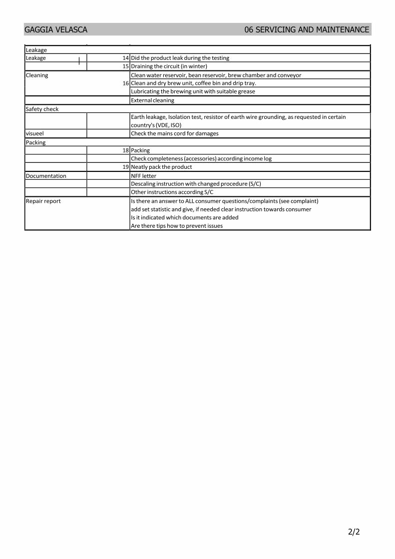
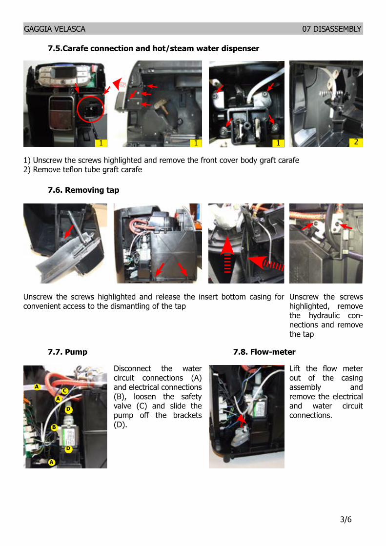
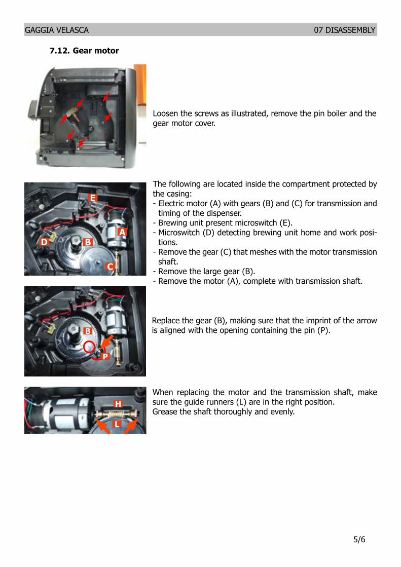
GAGGIA VELASCA
CHAPTER 6 SERVICING AND MAINTENANCE
GAGGIA VELASCA 06 SERVICING AND MAINTENANCE
12
61 Repair flow
Repair Flow
Proces stap Saeco no Action Intake 1
2 Visual inspection (transport damage) take care for picturesCheck Typeserialnumber Log all available accessory
Diagnosis 3 4
5 6
Check product for consumer complaint (NFF contact consumer)Opening machine Run Diagnostic to get error codes and relevant set statistics (Saeco Service Center SSC) Visual inspection check for loosen parts leaking etc Operational tests
Repair 7
8 9
10
11
12 13
14
15
Repairing the faults encounteredChecking any modifications (view Symptom Cure new software etc) Refer Annex tabs per family Service activities in accordance with the operating schedule CheckReplace Waterfilter (the small filter not the Britta filter) CheckReplace Water tank lip seal CheckReplace Boiler pin O‐ring Cleanalign Coffee grinder (Vacuum cleaner brush) Descale the water Circuit CheckReplace Hot watersteam valve Internal check cleaning CheckCleanGrease Brewing unit Operational test while the appliance is open Check Hoses attachments and Oetiker clamps Check Pump for operation amp noise Check Gear motor for operation amp noise Check for leakage Assembly Final inspection test Steam out before shipping out if temperature is below 0deg to prevent any demaged due to frozen water No need for those families Minuto family (all platform) Incanto family new Pico Baristo Gran Baristo Intelia V2 Philips 2000‐2100 Incanto Executive Moltio family (all platform) Please also check for GDA_113455
Provide precise IRIS code according dedicated code table for Coffee products Thelocation code from the part you have worked on MUST be completed always with the part reference from exploded view
Inspection visual Power check Accesoires Consumer complaint
Do cabinet parts fit well together Check for damages Will the set switch on Do the accessories match with the intake Check the product for the consumer complaint
Coffee Basic Functional test Dispense Make 2 coffee Are both amounts equal
Make e 2 cups at the same time Are the volumes equal Noise Is the sound normal Crema Blow on the coffee Does the crema come back together
Is the crema colour correct (Hazelnut) Temperature Is the coffee temperature within spec Grinder Is the grinder noise normal Steam Steam Does the steam work Hot Water Does the hot water work Milk (if applicable) Cappuchino Does the cappuccinatore produce good froth Leakage Leakage 14 Did the product leak during the testing
15 Draining the circuit (in winter) Cleaning
16 Clean water reservoir bean reservoir brew chamber and conveyorClean and dry brew unit coffee bin and drip tray Lubricating the brewing unit with suitable grease External cleaning
Safety check
Earth leakage Isolation test resistor of earth wire grounding as requested in certain countrys (VDE ISO)
visueel Check the mains cord for damages Packing
18 Packing Check completeness (accessories) according income log
19 Neatly pack the product Documentation NFF letter
Descaling instruction with changed procedure (SC) Other instructions according SC
Repair report Is there an answer to ALL consumer questionscomplaints (see complaint) add set statistic and give if needed clear instruction towards consumer Is it indicated which documents are added Are there tips how to prevent issues
GAGGIA VELASCA 06 SERVICING AND MAINTENANCE
22
Repair Flow
Proces stap Saeco no Action Intake 1
2 Visual inspection (transport damage) take care for picturesCheck Typeserialnumber Log all available accessory
Diagnosis 3 4
5 6
Check product for consumer complaint (NFF contact consumer)Opening machine Run Diagnostic to get error codes and relevant set statistics (Saeco Service Center SSC) Visual inspection check for loosen parts leaking etc Operational tests
Repair 7
8 9
10
11
12 13
14
15
Repairing the faults encounteredChecking any modifications (view Symptom Cure new software etc) Refer Annex tabs per family Service activities in accordance with the operating schedule CheckReplace Waterfilter (the small filter not the Britta filter) CheckReplace Water tank lip seal CheckReplace Boiler pin O‐ring Cleanalign Coffee grinder (Vacuum cleaner brush) Descale the water Circuit CheckReplace Hot watersteam valve Internal check cleaning CheckCleanGrease Brewing unit Operational test while the appliance is open Check Hoses attachments and Oetiker clamps Check Pump for operation amp noise Check Gear motor for operation amp noise Check for leakage Assembly Final inspection test Steam out before shipping out if temperature is below 0deg to prevent any demaged due to frozen water No need for those families Minuto family (all platform) Incanto family new Pico Baristo Gran Baristo Intelia V2 Philips 2000‐2100 Incanto Executive Moltio family (all platform) Please also check for GDA_113455
Provide precise IRIS code according dedicated code table for Coffee products Thelocation code from the part you have worked on MUST be completed always with the part reference from exploded view
Inspection visual Power check Accesoires Consumer complaint
Do cabinet parts fit well together Check for damages Will the set switch on Do the accessories match with the intake Check the product for the consumer complaint
Coffee Basic Functional test Dispense Make 2 coffee Are both amounts equal
Make e 2 cups at the same time Are the volumes equal Noise Is the sound normal Crema Blow on the coffee Does the crema come back together
Is the crema colour correct (Hazelnut) Temperature Is the coffee temperature within spec Grinder Is the grinder noise normal Steam Steam Does the steam work Hot Water Does the hot water work Milk (if applicable) Cappuchino Does the cappuccinatore produce good froth Leakage Leakage 14 Did the product leak during the testing
15 Draining the circuit (in winter) Cleaning
16 Clean water reservoir bean reservoir brew chamber and conveyorClean and dry brew unit coffee bin and drip tray Lubricating the brewing unit with suitable grease External cleaning
Safety check
Earth leakage Isolation test resistor of earth wire grounding as requested in certain countrys (VDE ISO)
visueel Check the mains cord for damages Packing
18 Packing Check completeness (accessories) according income log
19 Neatly pack the product Documentation NFF letter
Descaling instruction with changed procedure (SC) Other instructions according SC
Repair report Is there an answer to ALL consumer questionscomplaints (see complaint) add set statistic and give if needed clear instruction towards consumer Is it indicated which documents are added Are there tips how to prevent issues
GAGGIA VELASCA
CHAPTER 7 DISASSEMBLY
Unscrew the screws highlighted and re-move the finger protection
Unscrew the screws highlighted remove the rear housing and coverage for the soundproofing of the grinder
Unscrew the screws highlighted and Lift the grinder and remove the electrical connections
Remove the door
Unscrew the screws highlighted and remove the carcass left side
Lift the top cover
When reassembling the coffee grinder make sure the spring is repositioned cor-rectly (see photo)
GAGGIA VELASCA 07 DISASSEMBLY
16
71 Outer shell GAGGIA VELASCA OTC GAGGIA VELASCA CMF
Remove the water tank bean hop-per cover drip tray dump box brewing unit carafe or hot water dispenser pannarello or cap-pucinatore
72 Coffee grinder
73 Grinder blades
B
To extract the top sup-port of the appliance press on the grinding adjustment spindle (A) and turn the support anticlockwise until it unhooks
Turn the grinder blades anticlockwise out of the support
Turn the grinder blades clockwise out of the support The bayonet connections can be ac-cessed from the rear
For a standard adjust-ment both markings must be aligned
74 Coffee grinder adjustment
The grinding adjustment can be set by the user (only with the coffee grinder in operation) by pressing and turning (only by one click at a time) the insert inside the coffee bean hopper with the aid of the wrench supplied
+-
C+-
A
B
To adjust grinding further the engineer can work directly on the coffee grinder by pressing and turning the ring nut (C) shown (clockwise + to increase the particle size of the coffee and anticlockwise - to decrease it) If there are any remains of coffee powder between the two grinding blades it is recommended to tighten by max two marks at a timeLastly move the arrow (A) on the adjustment knob to the center of the adjustment dots on the cover (B)
GAGGIA VELASCA 07 DISASSEMBLY
26
A
Adjustment by a service center
75Carafe connection and hotsteam water dispenser
76 Removing tap
77 Pump 78 Flow-meter
1) Unscrew the screws highlighted and remove the front cover body graft carafe 2) Remove teflon tube graft carafe
1 21 1
Unscrew the screws highlighted and release the insert bottom casing for convenient access to the dismantling of the tap
Unscrew the screws highlighted remove the hydraulic con-nections and remove the tap
Disconnect the water circuit connections (A) and electrical connections (B) loosen the safety valve (C) and slide the pump off the brackets (D)
A
B
D
D
CA
A
Lift the flow meter out of the casing assembly and remove the electrical and water circuit connections
GAGGIA VELASCA 07 DISASSEMBLY
36
79 Boiler
Unscrew the screws highlighted and disconnect the electrical and water connections
Unscrew the screws highlighted and release the boiler cover and remove
Unscrew the screws hi-ghlighted remove the electrical connection highlighted and remo-ve lla card protection
Unscrew the screws highlighted and remove the frontal panel
Unscrew the screws highlighted and remove the keyboard trim and display
Unscrew the screws highlighted remove the electrical connections between the board and the display and release the card from the media
Remove the electrical con-nection and release the protective sheet
Remove the card from its holder and remo-ve the electrical con-nections
GAGGIA VELASCA 07 DISASSEMBLY
46
711 KYB interface and display
710 CPU board
GAGGIA VELASCA 07 DISASSEMBLY
56
712 Gear motor
Loosen the screws as illustrated remove the pin boiler and the gear motor cover
The following are located inside the compartment protected by the casing- Electric motor (A) with gears (B) and (C) for transmission and
timing of the dispenser- Brewing unit present microswitch (E)- Microswitch (D) detecting brewing unit home and work posi-
tions- Remove the gear (C) that meshes with the motor transmission
shaft- Remove the large gear (B)- Remove the motor (A) complete with transmission shaft
Replace the gear (B) making sure that the imprint of the arrow is aligned with the opening containing the pin (P)
When replacing the motor and the transmission shaft make sure the guide runners (L) are in the right positionGrease the shaft thoroughly and evenly
E
AB
C
D
B
P
H
L
GAGGIA VELASCA 07 DISASSEMBLY
66
1) Boiler connection
2) Other connections
Replacing the hoses
1) Use a suitable pair of pliers to remove the clamp (as illustrated)
2) Tighten the clamp as illustrated
1
1
2
2
713 Fitting and removing Oetiker clamps
GAGGIA VELASCA
CHAPTER 8 NOTES
GAGGIA VELASCA 08 NOTES
11
GAGGIA VELASCA
CHAPTER 9 WATER CIRCUIT DIAGRAM
GAGGIA VELASCA 09 WATER CIRCUIT DIAGRAM
11
91 Water circuit diagramFl
ow m
eter
Wat
er ta
nk
Assy
Sol
enoi
d va
lve
Wat
er d
rain
Pum
p
Boile
r
Safe
ty v
alve
Boile
r pin
Stea
m a
nd h
ot w
ater
GAGGIA VELASCA
CHAPTER 10 ELECTRICAL DIAGRAM
GAGGIA VELASCA 10 ELECTRICAL DIAGRAM
11
101 Electrical diagram
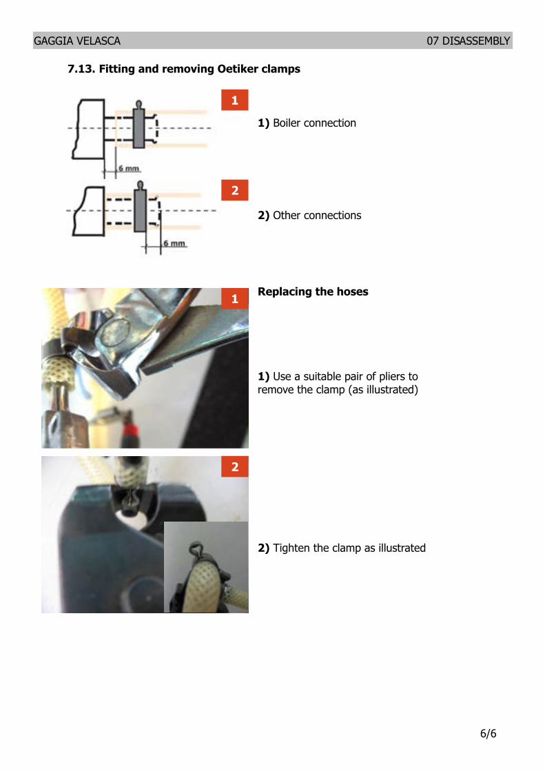
GAGGIA VELASCA 06 SERVICING AND MAINTENANCE
12
61 Repair flow
Repair Flow
Proces stap Saeco no Action Intake 1
2 Visual inspection (transport damage) take care for picturesCheck Typeserialnumber Log all available accessory
Diagnosis 3 4
5 6
Check product for consumer complaint (NFF contact consumer)Opening machine Run Diagnostic to get error codes and relevant set statistics (Saeco Service Center SSC) Visual inspection check for loosen parts leaking etc Operational tests
Repair 7
8 9
10
11
12 13
14
15
Repairing the faults encounteredChecking any modifications (view Symptom Cure new software etc) Refer Annex tabs per family Service activities in accordance with the operating schedule CheckReplace Waterfilter (the small filter not the Britta filter) CheckReplace Water tank lip seal CheckReplace Boiler pin O‐ring Cleanalign Coffee grinder (Vacuum cleaner brush) Descale the water Circuit CheckReplace Hot watersteam valve Internal check cleaning CheckCleanGrease Brewing unit Operational test while the appliance is open Check Hoses attachments and Oetiker clamps Check Pump for operation amp noise Check Gear motor for operation amp noise Check for leakage Assembly Final inspection test Steam out before shipping out if temperature is below 0deg to prevent any demaged due to frozen water No need for those families Minuto family (all platform) Incanto family new Pico Baristo Gran Baristo Intelia V2 Philips 2000‐2100 Incanto Executive Moltio family (all platform) Please also check for GDA_113455
Provide precise IRIS code according dedicated code table for Coffee products Thelocation code from the part you have worked on MUST be completed always with the part reference from exploded view
Inspection visual Power check Accesoires Consumer complaint
Do cabinet parts fit well together Check for damages Will the set switch on Do the accessories match with the intake Check the product for the consumer complaint
Coffee Basic Functional test Dispense Make 2 coffee Are both amounts equal
Make e 2 cups at the same time Are the volumes equal Noise Is the sound normal Crema Blow on the coffee Does the crema come back together
Is the crema colour correct (Hazelnut) Temperature Is the coffee temperature within spec Grinder Is the grinder noise normal Steam Steam Does the steam work Hot Water Does the hot water work Milk (if applicable) Cappuchino Does the cappuccinatore produce good froth Leakage Leakage 14 Did the product leak during the testing
15 Draining the circuit (in winter) Cleaning
16 Clean water reservoir bean reservoir brew chamber and conveyorClean and dry brew unit coffee bin and drip tray Lubricating the brewing unit with suitable grease External cleaning
Safety check
Earth leakage Isolation test resistor of earth wire grounding as requested in certain countrys (VDE ISO)
visueel Check the mains cord for damages Packing
18 Packing Check completeness (accessories) according income log
19 Neatly pack the product Documentation NFF letter
Descaling instruction with changed procedure (SC) Other instructions according SC
Repair report Is there an answer to ALL consumer questionscomplaints (see complaint) add set statistic and give if needed clear instruction towards consumer Is it indicated which documents are added Are there tips how to prevent issues
GAGGIA VELASCA 06 SERVICING AND MAINTENANCE
22
Repair Flow
Proces stap Saeco no Action Intake 1
2 Visual inspection (transport damage) take care for picturesCheck Typeserialnumber Log all available accessory
Diagnosis 3 4
5 6
Check product for consumer complaint (NFF contact consumer)Opening machine Run Diagnostic to get error codes and relevant set statistics (Saeco Service Center SSC) Visual inspection check for loosen parts leaking etc Operational tests
Repair 7
8 9
10
11
12 13
14
15
Repairing the faults encounteredChecking any modifications (view Symptom Cure new software etc) Refer Annex tabs per family Service activities in accordance with the operating schedule CheckReplace Waterfilter (the small filter not the Britta filter) CheckReplace Water tank lip seal CheckReplace Boiler pin O‐ring Cleanalign Coffee grinder (Vacuum cleaner brush) Descale the water Circuit CheckReplace Hot watersteam valve Internal check cleaning CheckCleanGrease Brewing unit Operational test while the appliance is open Check Hoses attachments and Oetiker clamps Check Pump for operation amp noise Check Gear motor for operation amp noise Check for leakage Assembly Final inspection test Steam out before shipping out if temperature is below 0deg to prevent any demaged due to frozen water No need for those families Minuto family (all platform) Incanto family new Pico Baristo Gran Baristo Intelia V2 Philips 2000‐2100 Incanto Executive Moltio family (all platform) Please also check for GDA_113455
Provide precise IRIS code according dedicated code table for Coffee products Thelocation code from the part you have worked on MUST be completed always with the part reference from exploded view
Inspection visual Power check Accesoires Consumer complaint
Do cabinet parts fit well together Check for damages Will the set switch on Do the accessories match with the intake Check the product for the consumer complaint
Coffee Basic Functional test Dispense Make 2 coffee Are both amounts equal
Make e 2 cups at the same time Are the volumes equal Noise Is the sound normal Crema Blow on the coffee Does the crema come back together
Is the crema colour correct (Hazelnut) Temperature Is the coffee temperature within spec Grinder Is the grinder noise normal Steam Steam Does the steam work Hot Water Does the hot water work Milk (if applicable) Cappuchino Does the cappuccinatore produce good froth Leakage Leakage 14 Did the product leak during the testing
15 Draining the circuit (in winter) Cleaning
16 Clean water reservoir bean reservoir brew chamber and conveyorClean and dry brew unit coffee bin and drip tray Lubricating the brewing unit with suitable grease External cleaning
Safety check
Earth leakage Isolation test resistor of earth wire grounding as requested in certain countrys (VDE ISO)
visueel Check the mains cord for damages Packing
18 Packing Check completeness (accessories) according income log
19 Neatly pack the product Documentation NFF letter
Descaling instruction with changed procedure (SC) Other instructions according SC
Repair report Is there an answer to ALL consumer questionscomplaints (see complaint) add set statistic and give if needed clear instruction towards consumer Is it indicated which documents are added Are there tips how to prevent issues
GAGGIA VELASCA
CHAPTER 7 DISASSEMBLY
Unscrew the screws highlighted and re-move the finger protection
Unscrew the screws highlighted remove the rear housing and coverage for the soundproofing of the grinder
Unscrew the screws highlighted and Lift the grinder and remove the electrical connections
Remove the door
Unscrew the screws highlighted and remove the carcass left side
Lift the top cover
When reassembling the coffee grinder make sure the spring is repositioned cor-rectly (see photo)
GAGGIA VELASCA 07 DISASSEMBLY
16
71 Outer shell GAGGIA VELASCA OTC GAGGIA VELASCA CMF
Remove the water tank bean hop-per cover drip tray dump box brewing unit carafe or hot water dispenser pannarello or cap-pucinatore
72 Coffee grinder
73 Grinder blades
B
To extract the top sup-port of the appliance press on the grinding adjustment spindle (A) and turn the support anticlockwise until it unhooks
Turn the grinder blades anticlockwise out of the support
Turn the grinder blades clockwise out of the support The bayonet connections can be ac-cessed from the rear
For a standard adjust-ment both markings must be aligned
74 Coffee grinder adjustment
The grinding adjustment can be set by the user (only with the coffee grinder in operation) by pressing and turning (only by one click at a time) the insert inside the coffee bean hopper with the aid of the wrench supplied
+-
C+-
A
B
To adjust grinding further the engineer can work directly on the coffee grinder by pressing and turning the ring nut (C) shown (clockwise + to increase the particle size of the coffee and anticlockwise - to decrease it) If there are any remains of coffee powder between the two grinding blades it is recommended to tighten by max two marks at a timeLastly move the arrow (A) on the adjustment knob to the center of the adjustment dots on the cover (B)
GAGGIA VELASCA 07 DISASSEMBLY
26
A
Adjustment by a service center
75Carafe connection and hotsteam water dispenser
76 Removing tap
77 Pump 78 Flow-meter
1) Unscrew the screws highlighted and remove the front cover body graft carafe 2) Remove teflon tube graft carafe
1 21 1
Unscrew the screws highlighted and release the insert bottom casing for convenient access to the dismantling of the tap
Unscrew the screws highlighted remove the hydraulic con-nections and remove the tap
Disconnect the water circuit connections (A) and electrical connections (B) loosen the safety valve (C) and slide the pump off the brackets (D)
A
B
D
D
CA
A
Lift the flow meter out of the casing assembly and remove the electrical and water circuit connections
GAGGIA VELASCA 07 DISASSEMBLY
36
79 Boiler
Unscrew the screws highlighted and disconnect the electrical and water connections
Unscrew the screws highlighted and release the boiler cover and remove
Unscrew the screws hi-ghlighted remove the electrical connection highlighted and remo-ve lla card protection
Unscrew the screws highlighted and remove the frontal panel
Unscrew the screws highlighted and remove the keyboard trim and display
Unscrew the screws highlighted remove the electrical connections between the board and the display and release the card from the media
Remove the electrical con-nection and release the protective sheet
Remove the card from its holder and remo-ve the electrical con-nections
GAGGIA VELASCA 07 DISASSEMBLY
46
711 KYB interface and display
710 CPU board
GAGGIA VELASCA 07 DISASSEMBLY
56
712 Gear motor
Loosen the screws as illustrated remove the pin boiler and the gear motor cover
The following are located inside the compartment protected by the casing- Electric motor (A) with gears (B) and (C) for transmission and
timing of the dispenser- Brewing unit present microswitch (E)- Microswitch (D) detecting brewing unit home and work posi-
tions- Remove the gear (C) that meshes with the motor transmission
shaft- Remove the large gear (B)- Remove the motor (A) complete with transmission shaft
Replace the gear (B) making sure that the imprint of the arrow is aligned with the opening containing the pin (P)
When replacing the motor and the transmission shaft make sure the guide runners (L) are in the right positionGrease the shaft thoroughly and evenly
E
AB
C
D
B
P
H
L
GAGGIA VELASCA 07 DISASSEMBLY
66
1) Boiler connection
2) Other connections
Replacing the hoses
1) Use a suitable pair of pliers to remove the clamp (as illustrated)
2) Tighten the clamp as illustrated
1
1
2
2
713 Fitting and removing Oetiker clamps
GAGGIA VELASCA
CHAPTER 8 NOTES
GAGGIA VELASCA 08 NOTES
11
GAGGIA VELASCA
CHAPTER 9 WATER CIRCUIT DIAGRAM
GAGGIA VELASCA 09 WATER CIRCUIT DIAGRAM
11
91 Water circuit diagramFl
ow m
eter
Wat
er ta
nk
Assy
Sol
enoi
d va
lve
Wat
er d
rain
Pum
p
Boile
r
Safe
ty v
alve
Boile
r pin
Stea
m a
nd h
ot w
ater
GAGGIA VELASCA
CHAPTER 10 ELECTRICAL DIAGRAM
GAGGIA VELASCA 10 ELECTRICAL DIAGRAM
11
101 Electrical diagram

GAGGIA VELASCA
CHAPTER 7 DISASSEMBLY
Unscrew the screws highlighted and re-move the finger protection
Unscrew the screws highlighted remove the rear housing and coverage for the soundproofing of the grinder
Unscrew the screws highlighted and Lift the grinder and remove the electrical connections
Remove the door
Unscrew the screws highlighted and remove the carcass left side
Lift the top cover
When reassembling the coffee grinder make sure the spring is repositioned cor-rectly (see photo)
GAGGIA VELASCA 07 DISASSEMBLY
16
71 Outer shell GAGGIA VELASCA OTC GAGGIA VELASCA CMF
Remove the water tank bean hop-per cover drip tray dump box brewing unit carafe or hot water dispenser pannarello or cap-pucinatore
72 Coffee grinder
73 Grinder blades
B
To extract the top sup-port of the appliance press on the grinding adjustment spindle (A) and turn the support anticlockwise until it unhooks
Turn the grinder blades anticlockwise out of the support
Turn the grinder blades clockwise out of the support The bayonet connections can be ac-cessed from the rear
For a standard adjust-ment both markings must be aligned
74 Coffee grinder adjustment
The grinding adjustment can be set by the user (only with the coffee grinder in operation) by pressing and turning (only by one click at a time) the insert inside the coffee bean hopper with the aid of the wrench supplied
+-
C+-
A
B
To adjust grinding further the engineer can work directly on the coffee grinder by pressing and turning the ring nut (C) shown (clockwise + to increase the particle size of the coffee and anticlockwise - to decrease it) If there are any remains of coffee powder between the two grinding blades it is recommended to tighten by max two marks at a timeLastly move the arrow (A) on the adjustment knob to the center of the adjustment dots on the cover (B)
GAGGIA VELASCA 07 DISASSEMBLY
26
A
Adjustment by a service center
75Carafe connection and hotsteam water dispenser
76 Removing tap
77 Pump 78 Flow-meter
1) Unscrew the screws highlighted and remove the front cover body graft carafe 2) Remove teflon tube graft carafe
1 21 1
Unscrew the screws highlighted and release the insert bottom casing for convenient access to the dismantling of the tap
Unscrew the screws highlighted remove the hydraulic con-nections and remove the tap
Disconnect the water circuit connections (A) and electrical connections (B) loosen the safety valve (C) and slide the pump off the brackets (D)
A
B
D
D
CA
A
Lift the flow meter out of the casing assembly and remove the electrical and water circuit connections
GAGGIA VELASCA 07 DISASSEMBLY
36
79 Boiler
Unscrew the screws highlighted and disconnect the electrical and water connections
Unscrew the screws highlighted and release the boiler cover and remove
Unscrew the screws hi-ghlighted remove the electrical connection highlighted and remo-ve lla card protection
Unscrew the screws highlighted and remove the frontal panel
Unscrew the screws highlighted and remove the keyboard trim and display
Unscrew the screws highlighted remove the electrical connections between the board and the display and release the card from the media
Remove the electrical con-nection and release the protective sheet
Remove the card from its holder and remo-ve the electrical con-nections
GAGGIA VELASCA 07 DISASSEMBLY
46
711 KYB interface and display
710 CPU board
GAGGIA VELASCA 07 DISASSEMBLY
56
712 Gear motor
Loosen the screws as illustrated remove the pin boiler and the gear motor cover
The following are located inside the compartment protected by the casing- Electric motor (A) with gears (B) and (C) for transmission and
timing of the dispenser- Brewing unit present microswitch (E)- Microswitch (D) detecting brewing unit home and work posi-
tions- Remove the gear (C) that meshes with the motor transmission
shaft- Remove the large gear (B)- Remove the motor (A) complete with transmission shaft
Replace the gear (B) making sure that the imprint of the arrow is aligned with the opening containing the pin (P)
When replacing the motor and the transmission shaft make sure the guide runners (L) are in the right positionGrease the shaft thoroughly and evenly
E
AB
C
D
B
P
H
L
GAGGIA VELASCA 07 DISASSEMBLY
66
1) Boiler connection
2) Other connections
Replacing the hoses
1) Use a suitable pair of pliers to remove the clamp (as illustrated)
2) Tighten the clamp as illustrated
1
1
2
2
713 Fitting and removing Oetiker clamps
GAGGIA VELASCA
CHAPTER 8 NOTES
GAGGIA VELASCA 08 NOTES
11
GAGGIA VELASCA
CHAPTER 9 WATER CIRCUIT DIAGRAM
GAGGIA VELASCA 09 WATER CIRCUIT DIAGRAM
11
91 Water circuit diagramFl
ow m
eter
Wat
er ta
nk
Assy
Sol
enoi
d va
lve
Wat
er d
rain
Pum
p
Boile
r
Safe
ty v
alve
Boile
r pin
Stea
m a
nd h
ot w
ater
GAGGIA VELASCA
CHAPTER 10 ELECTRICAL DIAGRAM
GAGGIA VELASCA 10 ELECTRICAL DIAGRAM
11
101 Electrical diagram
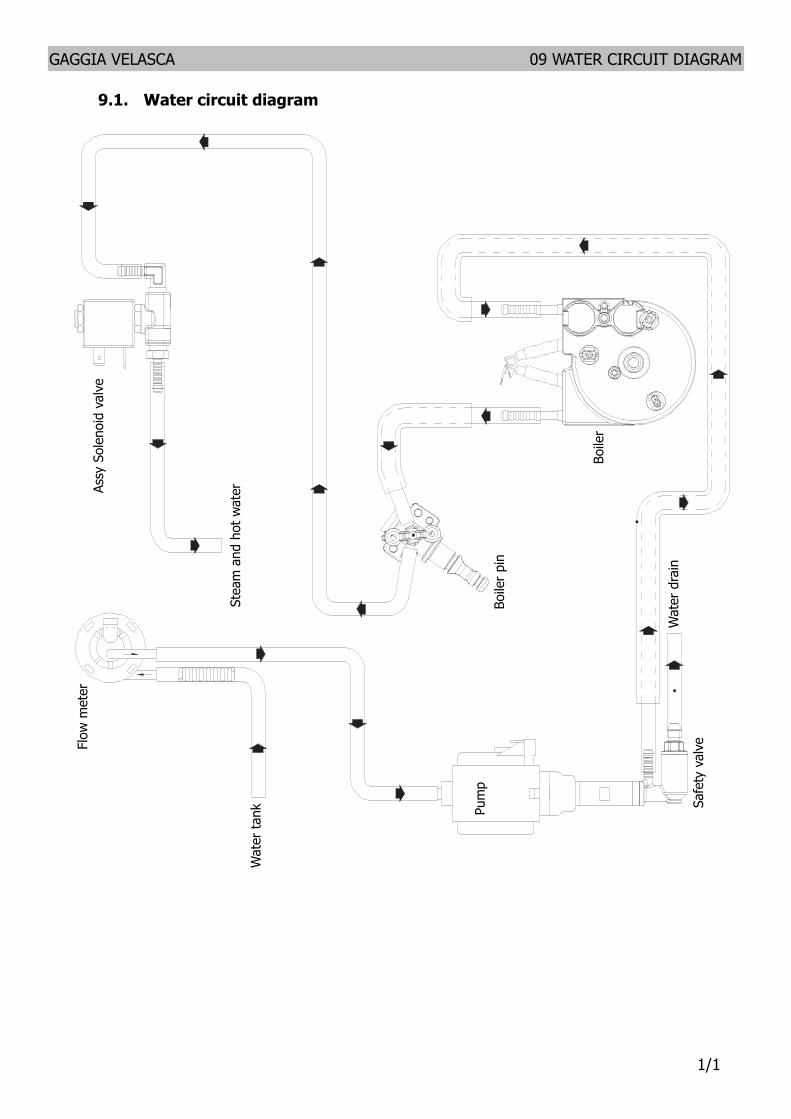

GAGGIA VELASCA 07 DISASSEMBLY
66
1) Boiler connection
2) Other connections
Replacing the hoses
1) Use a suitable pair of pliers to remove the clamp (as illustrated)
2) Tighten the clamp as illustrated
1
1
2
2
713 Fitting and removing Oetiker clamps
GAGGIA VELASCA
CHAPTER 8 NOTES
GAGGIA VELASCA 08 NOTES
11
GAGGIA VELASCA
CHAPTER 9 WATER CIRCUIT DIAGRAM
GAGGIA VELASCA 09 WATER CIRCUIT DIAGRAM
11
91 Water circuit diagramFl
ow m
eter
Wat
er ta
nk
Assy
Sol
enoi
d va
lve
Wat
er d
rain
Pum
p
Boile
r
Safe
ty v
alve
Boile
r pin
Stea
m a
nd h
ot w
ater
GAGGIA VELASCA
CHAPTER 10 ELECTRICAL DIAGRAM
GAGGIA VELASCA 10 ELECTRICAL DIAGRAM
11
101 Electrical diagram

GAGGIA VELASCA
CHAPTER 8 NOTES
GAGGIA VELASCA 08 NOTES
11
GAGGIA VELASCA
CHAPTER 9 WATER CIRCUIT DIAGRAM
GAGGIA VELASCA 09 WATER CIRCUIT DIAGRAM
11
91 Water circuit diagramFl
ow m
eter
Wat
er ta
nk
Assy
Sol
enoi
d va
lve
Wat
er d
rain
Pum
p
Boile
r
Safe
ty v
alve
Boile
r pin
Stea
m a
nd h
ot w
ater
GAGGIA VELASCA
CHAPTER 10 ELECTRICAL DIAGRAM
GAGGIA VELASCA 10 ELECTRICAL DIAGRAM
11
101 Electrical diagram

GAGGIA VELASCA
CHAPTER 9 WATER CIRCUIT DIAGRAM
GAGGIA VELASCA 09 WATER CIRCUIT DIAGRAM
11
91 Water circuit diagramFl
ow m
eter
Wat
er ta
nk
Assy
Sol
enoi
d va
lve
Wat
er d
rain
Pum
p
Boile
r
Safe
ty v
alve
Boile
r pin
Stea
m a
nd h
ot w
ater
GAGGIA VELASCA
CHAPTER 10 ELECTRICAL DIAGRAM
GAGGIA VELASCA 10 ELECTRICAL DIAGRAM
11
101 Electrical diagram

GAGGIA VELASCA
CHAPTER 10 ELECTRICAL DIAGRAM
GAGGIA VELASCA 10 ELECTRICAL DIAGRAM
11
101 Electrical diagram

GAGGIA VELASCA 10 ELECTRICAL DIAGRAM
11
101 Electrical diagram