service manual af2035e.pdf
TRANSCRIPT

Model A-C3e/f (Machine Code: B135/B138)
SERVICE MANUAL

IIMPORTANT SAFETY NOTICES
PREVENTION OF PHYSICAL INJURY
1. Before disassembling or assembling parts of the copier and peripherals, make sure that the copier power cord is unplugged.
2. The wall outlet should be near the copier and easily accessible. 3. Note that some components of the copier and the paper tray unit are
supplied with electrical voltage even if the main power switch is turned off. 4. If any adjustment or operation check has to be made with exterior covers off
or open while the main switch is turned on, keep hands away from electrified or mechanically driven components.
5. If the Start key is pressed before the copier completes the warm-up period (the Start key starts blinking red and green alternatively), keep hands away from the mechanical and the electrical components as the copier starts making copies as soon as the warm-up period is completed.
6. The inside and the metal parts of the fusing unit become extremely hot while the copier is operating. Be careful to avoid touching those components with your bare hands.
HEALTH SAFETY CONDITIONS
1. Never operate the copier without the ozone filters installed. 2. Always replace the ozone filters with the specified ones at the specified
intervals. 3. Toner and developer are non-toxic, but if you get either of them in your eyes
by accident, it may cause temporary eye discomfort. Try to remove with eye drops or flush with water as first aid. If unsuccessful, get medical attention.
OBSERVANCE OF ELECTRICAL SAFETY STANDARDS 1. The copier and its peripherals must be installed and maintained by a
customer service representative who has completed the training course on those models.
2. The NVRAM on the system control board has a lithium battery which can explode if replaced incorrectly. Replace the NVRAM only with an identical one. The manufacturer recommends replacing the entire NVRAM. Do not recharge or burn this battery. Used NVRAM must be handled in accordance with local regulations.

1. SAFETY AND ECOLOGICAL NOTES FOR DISPOSAL Do not incinerate toner bottles or used toner. Toner dust may ignite suddenly when exposed to an open flame.
2. Dispose of used toner, developer, and organic photoconductors in accordance with local regulations. (These are non-toxic supplies.)
3. Dispose of replaced parts in accordance with local regulations. 4. When keeping used lithium batteries in order to dispose of them later, do not
put more than 100 batteries per sealed box. Storing larger numbers or not sealing them apart may lead to chemical reactions and heat build-up.
LASER SAFETY The Center for Devices and Radiological Health (CDRH) prohibits the repair of laser-based optical units in the field. The optical housing unit can only be repaired in a factory or at a location with the requisite equipment. The laser subsystem is replaceable in the field by a qualified Customer Engineer. The laser chassis is not repairable in the field. Customer engineers are therefore directed to return all chassis and laser subsystems to the factory or service depot when replacement of the optical subsystem is required.
!WARNING Use of controls, or adjustment, or performance of procedures other than those specified in this manual may result in hazardous radiation exposure.
!WARNING WARNING: Turn off the main switch before attempting any of the procedures in the Laser Unit section. Laser beams can seriously damage your eyes. CAUTION MARKING:

Conventions in this Manual This manual uses several symbols.
Symbol What it means ☛ Refer to section number ! See Core Tech Manual for details " Screw # Connector $ E-ring % Clip ring
Long Edge Feed (LEF)Short Edge Feed (SEF)

i
TABLE OF CONTENTS
1. INSTALLATION PROCEDURE................................................... 1-1 1.1 INSTALLATION REQUIREMENTS........................................................... 1-1
1.1.1 ENVIRONMENT .............................................................................. 1-2 1.1.2 MACHINE LEVEL ............................................................................ 1-2 1.1.3 MINIMUM SPACE REQUIREMENTS.............................................. 1-3 1.1.4 POWER REQUIREMENTS.............................................................. 1-5
1.2 INSTALLATION FLOW CHART................................................................ 1-6 1.3 MAIN MACHINE INSTALLATION............................................................. 1-7
1.3.1 ACCESSORY CHECK..................................................................... 1-7 1.3.2 INSTALLATION PROCEDURE........................................................ 1-8
Development Unit and PCU ................................................................. 1-9 Toner Bottle........................................................................................ 1-12 Paper Trays........................................................................................ 1-13 Initialize TD Sensor and Developer.................................................... 1-15 Set Paper Size for Paper Trays.......................................................... 1-16 Electrical Total Counter...................................................................... 1-17 HDD Caution Decal............................................................................ 1-17 Exposure Glass Cleaner .................................................................... 1-17
1.4 PAPER TRAY UNIT INSTALLATION (B542).......................................... 1-18 1.4.1 ACCESSORY CHECK................................................................... 1-18 1.4.2 PAPER TRAY UNIT INSTALLATION PROCEDURE..................... 1-19
1.5 1-BIN TRAY UNIT INSTALLATION (B544)............................................. 1-23 1.5.1 ACCESSORY CHECK................................................................... 1-23 1.5.2 1-BIN TRAY INSTALLATION PROCEDURE................................. 1-24
1.6 BRIDGE UNIT INSTALLATION (B538)................................................... 1-30 1.6.1 ACCESSORY CHECK................................................................... 1-30 1.6.2 BRIDGE UNIT INSTALLATION PROCEDURE.............................. 1-31
1.7 TWO-TRAY FINISHER INSTALLATION (B545)..................................... 1-33 1.7.1 ACCESSORY CHECK................................................................... 1-33 1.7.2 TWO-TRAY FINISHER INSTALLATION PROCEDURE................ 1-34
1.8 PUNCH UNIT INSTALLATION ............................................................... 1-37 1.8.1 ACCESSORY CHECK................................................................... 1-37 1.8.2 PUNCH UNIT INSTALLATION PROCEDURE............................... 1-38
1.9 ARDF INSTALLATION (B541)................................................................ 1-41 1.9.1 ACCESSORY CHECK................................................................... 1-41 1.9.2 ARDF INSTALLATION PROCEDURE........................................... 1-41 1.9.3 ARDF SKEW ADJUSTMENT......................................................... 1-44
1.10 LCT INSTALLATION (B543)................................................................. 1-45 1.10.1 ACCESSORY CHECK................................................................. 1-45 1.10.2 LCT INSTALLATION PROCEDURE............................................ 1-46
1.11 PLATEN COVER INSTALLATION (G329)............................................ 1-48 1.12 BOOKLET FINISHER INSTALLATION (B546) ..................................... 1-49
1.12.1 ACCESSORY CHECK................................................................. 1-49 1.12.2 BOOKLET FINISHER INSTALLATION PROCEDURE ................ 1-50
ii
1.13 1000 SHEET FINISHER (B408) ........................................................... 1-55 1.13.1 ACCESSORY CHECK................................................................. 1-55 1.13.2 1000 SHEET FINISHER INSTALLATION PROCEDURE ............ 1-56
1.14 FILE FORMAT CONVERTER B519-17 ................................................ 1-59 1.14.1 ACCESSORY CHECK................................................................. 1-59 1.14.2 INSTALLATION PROCEDURE.................................................... 1-59 1.14.3 CHECK ALL CONNECTIONS...................................................... 1-60
2. PREVENTIVE MAINTENANCE SCHEDULE............................... 2-1 2.1 PM TABLE................................................................................................ 2-1
3. REPLACEMENT AND ADJUSTMENT........................................ 3-1 3.1 SPECIAL TOOLS AND LUBRICANTS ............................................... 3-2 3.1.1 SPECIAL TOOLS............................................................................. 3-2 3.1.2 LUBRICANTS .................................................................................. 3-2
3.2 LASER UNIT............................................................................................. 3-3 3.2.1 CAUTION DECAL LOCATIONS ...................................................... 3-3 3.2.2 LASER UNIT.................................................................................... 3-4
3.3 PHOTOCONDUCTOR UNIT (PCU).......................................................... 3-6 3.3.1 PCU ................................................................................................. 3-6 3.3.2 DRUM .............................................................................................. 3-7 3.3.3 PICK-OFF PAWLS........................................................................... 3-9
Pick-off pawl position adjustment ......................................................... 3-9 3.3.4 CHARGE ROLLER AND CLEANING ROLLER ............................. 3-10 3.3.5 DRUM CLEANING BLADE 2 ......................................................... 3-11 3.3.6 DRUM CLEANING BLADE 1 ......................................................... 3-12
3.4 FUSING UNIT......................................................................................... 3-13 3.4.1 FUSING UNIT REMOVAL.............................................................. 3-13 3.4.2 FUSING UNIT SIDE FAN............................................................... 3-14 3.4.3 FUSING UNIT CORNER FAN ....................................................... 3-16
3.5 PAPER FEED......................................................................................... 3-17 3.5.1 IDLE ROLLER DUST BLADE ........................................................ 3-17 3.5.2 REGISTRATION ROLLER DUST BLADE ..................................... 3-18
3.6 PRINTED CIRCUIT BOARDS ................................................................ 3-19 3.6.1 IOB................................................................................................. 3-19
IOB DIP Switch Settings (SW101) ..................................................... 3-20 3.7 HARD DISK, CONTROLLER BOARD .................................................... 3-21
4. TROUBLESHOOTING................................................................. 4-1 4.1 SERVICE CALL CONDITIONS................................................................. 4-1
4.1.1 SUMMARY....................................................................................... 4-1 4.1.2 SC CODE DESCRIPTIONS............................................................. 4-2
4.2 ELECTRICAL COMPONENT DEFECTS................................................ 4-10 4.2.1 SENSORS ..................................................................................... 4-10 4.2.2 SWITCHES.................................................................................... 4-11
4.3 BLOWN FUSE CONDITIONS................................................................. 4-11 4.4 LEDS ...................................................................................................... 4-12 4.5 TEST POINTS ........................................................................................ 4-12

iii
5. SERVICE TABLES...................................................................... 5-1 5.1 SERVICE PROGRAM MODE TABLES .................................................... 5-1
5.1.1 SERVICE TABLE KEY..................................................................... 5-1 5.1.2 SERVICE TABLES .......................................................................... 5-2
SP1-xxx: Feed...................................................................................... 5-2 SP2-xxx: Drum..................................................................................... 5-6 SP3-xxx: Process............................................................................... 5-16 SP4-xxx: Scanner .............................................................................. 5-17 SP5-xxx: Mode................................................................................... 5-26 SP6-xxx: Peripherals.......................................................................... 5-46 SP7-xxx: Data Log ............................................................................. 5-48 SP8-xxx: Data Log2 ........................................................................... 5-56
5.1.3 TEST PATTERN PRINTING: SP2-902 .......................................... 5-90 Test Pattern Table (SP2-902-2: IPU Test Print) ................................. 5-90 Test Pattern Table: SP2-902-3 Printing Test Patterns ....................... 5-91
5.1.4 INPUT CHECK............................................................................... 5-92 Main Machine Input Check: SP5-803................................................. 5-92 ARDF Input Check: SP6-007 ............................................................. 5-96
5.1.5 OUTPUT CHECK........................................................................... 5-97 Main Machine Output Check: SP5-804 .............................................. 5-97 ARDF Output Check: SP6-008) ......................................................... 5-99
5.1.6 SMC PRINT OUT LISTS: SP5-990................................................ 5-99 5.1.7 MEMORY CLEAR: SP5-801........................................................ 5-100
5.2 DIP SWITCHES.................................................................................... 5-102 5.3 USING THE DEBUG LOG.................................................................... 5-103
5.3.1 SWITCHING ON AND SETTING UP SAVE DEBUG LOG .......... 5-103 5.3.2 RETRIEVING THE DEBUG LOG FROM THE HDD ................... 5-107 5.3.3 RECORDING ERRORS MANUALLY .......................................... 5-107
6. DETAILED SECTIOIN DESCRIPTIONS...................................... 6-1 6.1 BOARD STRUCTURE.............................................................................. 6-2
6.1.1 BLOCK DIAGRAM........................................................................... 6-2 6.1.2 CONTROLLER ................................................................................ 6-4
6.2 IMAGE PROCESSING ............................................................................. 6-7 6.2.1 OVERVIEW...................................................................................... 6-7 6.2.2 SBU (SENSOR BOARD UNIT) ........................................................ 6-8 6.2.3 AUTO IMAGE DENSITY (ADS) ....................................................... 6-9 6.2.4 IPU (IMAGE PROCESSING UNIT)................................................ 6-10
Overview ............................................................................................ 6-10 6.2.5 IMAGE PROCESSING MODES .................................................... 6-11 6.2.6 SUMMARY OF IMAGE PROCESSING FUNCTIONS ................... 6-13 6.2.7 IMAGE PROCESSING STEPS AND RELATED SP MODES........ 6-14
Text Mode .......................................................................................... 6-14 Text/Photo Mode................................................................................ 6-15 Photo Mode........................................................................................ 6-16 Pale (Low-Density Mode)................................................................... 6-17 Generation Copy Mode ...................................................................... 6-18

iv
6.2.8 PRE-FILTERING............................................................................ 6-19 6.2.9 BACKGROUND ERASE ................................................................ 6-20 6.2.10 INDEPENDENT DOT ERASE...................................................... 6-21 6.2.11 LINE WIDTH CORRECTION ....................................................... 6-22 6.2.12 FILTERING .................................................................................. 6-23
Interactive SP Codes ......................................................................... 6-23 Text Mode MTF Filter......................................................................... 6-27 Text/Photo, Photo Mode Filter............................................................ 6-28 Pale, Generation Mode Filter ............................................................. 6-29 Photo Mode Smoothing for Dithering ................................................. 6-30 Photo Mode Grayscale....................................................................... 6-30 Photo Mode Image Quality................................................................. 6-31
6.2.13 OTHERS...................................................................................... 6-32 Vertical Black Line Correction ............................................................ 6-32 Density Settings ................................................................................. 6-32 ADS Level .......................................................................................... 6-33
6.2.14 PRACTICAL APPLICATION OF SP MODES .............................. 6-34 Solving Problems ............................................................................... 6-34 Recommended Settings for MTF Filters............................................. 6-35
6.3 PHOTOCONDUCTOR UNIT (PCU)........................................................ 6-37 6.3.1 OVERVIEW.................................................................................... 6-37 6.3.2 DRUM CLEANING......................................................................... 6-38
6.4 DRUM CHARGE..................................................................................... 6-39 6.4.1 CORRECTION FOR PAPER WIDTH AND THICKNESS............... 6-39 6.4.2 DEVELOPMENT BIAS................................................................... 6-40
Mechanism......................................................................................... 6-40 Correction for paper width and thickness (by-pass tray only)............. 6-40
6.5 PAPER FEED......................................................................................... 6-41 6.5.1 PAPER REGISTRATION............................................................... 6-41
6.6 IMAGE FUSING AND PAPER EXIT ....................................................... 6-42 6.6.1 CLEANING MECHANISM.............................................................. 6-42 6.6.2 HOT ROLLER STRIPPER CLEANING.......................................... 6-43 6.6.3 FUSING TEMPERATURE CONTROL........................................... 6-45
Temperature Control .......................................................................... 6-46 Fusing Idling Temperature ................................................................. 6-47
6.6.4 CPM DOWN FOR THICK PAPER ................................................. 6-48 6.6.5 COOLING AND OVERHEAT PROTECTION................................. 6-49 6.6.6 TONER SCATTER PREVENTION ................................................ 6-50

v
PERIPHERALS BOOKLET FINISHER (B546)
1. OVERALL MACHINE INFORMATION ..................................B546-1 1.1 MECHANICAL COMPONENT LAYOUT............................................. B546-1
2. DETAILED DESCRIPTIONS .................................................B546-2 2.1 JUNCTION GATE MECHANISM ........................................................ B546-2
2.1.1 SHIFT TRAY MODE .................................................................. B546-2 A4/LT sideways or shorter ............................................................. B546-2 Longer than A4 sideways............................................................... B546-2
2.1.2 PROOF TRAY MODE................................................................ B546-3 2.1.3 BOOKLET STITCH MODE ........................................................ B546-3
2.2 PRE-STACK MECHANISM ................................................................ B546-4 2.3 PAPER SHIFT MECHANISM ............................................................. B546-5 2.4 PAPER POSITIONING MECHANISM ................................................ B546-6 2.5 STAPLER UNIT MOVEMENT MECHANISM...................................... B546-7
2.5.1 DRIVE........................................................................................ B546-7 2.5.2 MOVEMENT .............................................................................. B546-7
Front and Rear Stapling ................................................................. B546-7 Tow-position Stapling..................................................................... B546-7
2.6 STAPLER ........................................................................................... B546-8 2.7 SHIFT TRAY MECHANISM................................................................ B546-9 2.8 BOOKLET UNIT GATE MECHANISM.............................................. B546-10 2.9 RELAY ROLLER AND POSITIONING PLATE MECHANISM........... B546-12 2.10 POSITIONING ROLLER MECHANISM .......................................... B546-13 2.11 BOOKLET UNIT JOGGER MOVEMENT MECHANISM................. B546-14 2.12 BOOKLET STAPLER UNIT ............................................................ B546-15 2.13 PAPER FOLDER MECHANISM ..................................................... B546-16
3. REPLACEMENT AND ADJUSTMENT................................B546-18 3.1 REMOVAL ........................................................................................ B546-18
3.1.1 UPPER DOOR......................................................................... B546-18 3.1.2 UPPER REAR COVER............................................................ B546-19 3.1.3 LOWER REAR COVER ........................................................... B546-19 3.1.4 TOP COVER............................................................................ B546-20 3.1.5 UPPER INNER COVER........................................................... B546-20 3.1.6 SHIFT TRAY UNIT................................................................... B546-21 3.1.7 UPPER SHIFT GUIDE............................................................. B546-22 3.1.8 LOWER SHIFT GUIDE ............................................................ B546-22 3.1.9 EXIT UNIT................................................................................ B546-23 3.1.10 BUFFER ROLLER UNIT........................................................ B546-24 3.1.11 STAPLER............................................................................... B546-25 3.1.12 FINISHER BOARD ............................................................... B546-26 3.1.13 BOOKLET UNIT..................................................................... B546-27 3.1.14 FOLDER ROLLERS............................................................... B546-29

vi
3.1.15 FOLDER PLATE .................................................................... B546-32 Removal....................................................................................... B546-32 Reinstalling................................................................................... B546-33
3.1.16 BOOKLET STAPLER UNIT ................................................... B546-34 Removal....................................................................................... B546-34 Adjustment ................................................................................... B546-35
3.1.17 BOOKLET BOARD ................................................................ B546-37 3.1.18 POSITIONING PLATE UNIT.................................................. B546-37 3.1.19 1ST AND 2ND BOOKLET UNIT GATES ............................... B546-38
3.2 ADJUSTMENT.................................................................................. B546-39 3.2.1 SHIFT TRAY HEIGHT ............................................................. B546-39 3.2.2 JOGGER FENCE POSITION................................................... B546-40 3.2.3 STAPLING POSITION............................................................. B546-41 3.2.4 BOOKLET STAPLING POSITION ........................................... B546-42
SPECIFICATIONS.................................................................... SPEC-1 1. GENERAL SPECIFICATIONS.............................................................SPEC-1 2. MACHINE CONFIGURATION .............................................................SPEC-3 3. OPTIONAL EQUIPMENT ...................................................................SPEC-5

1 August, 2003 INSTALLATION REQUIREMENTS
1-1
Inst
alla
tion1. INSTALLATION PROCEDURE
!CAUTION Never turn off the main power switch when the power LED is lit or flashing. To avoid damaging the hard disk or memory, press the operation power switch to switch the power off, wait for the power LED to go off, and then switch the main power switch off.
NOTE: The main power LED lights or flashes while the platen cover or ARDF is
open, while the main machine is communicating with a facsimile or the network server, or while the machine is accessing the hard disk or memory for reading or writing data.
1.1 INSTALLATION REQUIREMENTS
!CAUTION
B135I016.WMF
�Rating Voltage of OutputConnector, Max. DC24 V�
LCT
�Rating Voltage of OutputConnector, Max. DC24 V�
Finisher
�Rating Voltage of OutputConnector, Max. DC24 V�
Scanner Unit
�Rating Voltage of OutputConnector, Max. DC24 V�
ARDF

INSTALLATION REQUIREMENTS 1 August, 2003
1-2
1.1.1 ENVIRONMENT
1. Temperature Range: 10 °C to 32 °C (50 °F to 90 °F)
2. Humidity Range: 15% to 80% RH
3. Ambient Illumination: Less than 1,500 lux (do not expose to direct sunlight.)
4. Ventilation: Room air should turn over at least 30 m3/hr/person
5. Ambient Dust: Less than 0.10 mg/m3 (2.7 x 10/6 oz/yd3)
6. Avoid areas exposed to sudden temperature changes: 1) Areas directly exposed to cool air from an air conditioner. 2) Areas directly exposed to heat from a heater.
7. Do not place the machine where it will be exposed to corrosive gases. 8. Do not install the machine at any location over 2,000 m (6,500 ft.) above sea
level. 9. Place the main machine on a strong and level base. Inclination on any side
should be no more than 5 mm (0.2"). 10. Do not place the machine where it may be subjected to strong vibrations. 1.1.2 MACHINE LEVEL
Front to back: Within 5 mm (0.2") of level Right to left: Within 5 mm (0.2") of level

1 August, 2003 INSTALLATION REQUIREMENTS
1-3
Inst
alla
tion
1.1.3 MINIMUM SPACE REQUIREMENTS
Place the main machine near the power source, providing clearance as shown:
NOTE: The 75 cm (29.5") recommended for the space at the front is for pulling out
the paper tray only. If the operator stands at the front of the main machine, more space is required.
B135I010.WMF
A: Front: >75 cm (29.6") B: Left: > 10 cm (4") C: Rear: > 10 cm (4") D: Right > 10 cm (4")
B
C
D
A

INSTALLATION REQUIREMENTS 1 August, 2003
1-4
B135I012.WMF
B135I014.WMF
670 mm (26.4") 180 mm (7.1")
726 mm (28.6") 670 mm (23.4") 620 mm (24.4")

1 August, 2003 INSTALLATION REQUIREMENTS
1-5
Inst
alla
tion
1.1.4 POWER REQUIREMENTS
!CAUTION 1. Make sure that the wall outlet is near the main machine and easily
accessible. Make sure the plug is firmly inserted in the outlet. 2. Avoid multi-wiring. 3. Be sure to ground the machine.
1. Input voltage level: North America 120 V, 60 Hz: More than 12.5 A Europe/Asia 220 V ~ 240V, 50 Hz/60 Hz: more than 6.8 A
2. Permissible voltage fluctuation: ±10 % 3. Never set anything on the power cord.

INSTALLATION FLOW CHART 1 August, 2003
1-6
1.2 INSTALLATION FLOW CHART The following flow chart shows how to install the optional units more efficiently.
Bridge Unit: Needed for the finishers and external output tray. Paper Tray Unit: Needed for LCT and finishers. Other requirements: See Overall Machine Information � Installation Option Table.
Unpack Copier
Install the copier
Install the bridge unit (if required)
Install the remaining options in any order
Place Copier on the paper tray unitInstall the paper tray unit
Does the user require the Paper Tray Unit, LCT, or Finisher?
Yes No
If the customer requires the 1-bin tray:Remove the scanner unitInstall the 1-bin trayReplace the scanner unit
B135I510.WMF

1 August, 2003 MAIN MACHINE INSTALLATION
1-7
Inst
alla
tion
1.3 MAIN MACHINE INSTALLATION 1.3.1 ACCESSORY CHECK
Check the quantity and condition of the accessories in the box against the following list: Description Q�ty
1. Operation Instructions � System Setting............................... 1 2. Operation Instructions � Copy Reference ............................. 1 3. Exposure Glass Cleaner Holder............................................ 1 4. Exposure Glass Cleaner ....................................................... 1 5. Paper Size Decal .................................................................. 1 6. Middle Front Cover................................................................ 1 7. NECR � English (-17, -19, -21, -28, -29, -57 Machines)........ 1 8. NECR � Multi-Language (-26, -27, -66, -67 Machines)......... 1 9. HDD Caution Decals (-17, -29, -57 Machines)...................... 1 10. Model Name Decal (-17, -29, -57 Machines) ........................ 1 11. Stamp (-17 Machine)............................................................. 1 12. EU Safety Information (-26, -27, -66, -67 Machines)............. 1 13. Operation Panel Indicator Decals
(-26, -27, -66, -67 Machines)................................................. 1 14. Address Information Sheet � China (-21 Machine) ............... 1 15. Paper Caution Sheet � China (-21 Machine) ........................ 1 16. Energy Start Sticker (-26, -66 Machines) .............................. 1

MAIN MACHINE INSTALLATION 1 August, 2003
1-8
1.3.2 INSTALLATION PROCEDURE
1. Remove the main machine from the box, and remove all shipping retainers and tapes. NOTE: Store all shipping retainers as you remove them. You will need them if
the machine is moved to another location in the future. 2. Remove scanner cushion [A], and install the end fence [B]. 3. Pull out the paper trays and remove all tape and bottom plate stoppers [C]. 4. On the right side of the machine, open the by-pass tray, duplex unit, and
transfer right cover, and then remove all the shipping retainers [D] NOTE: If the paper tray unit is to be installed, do this now. (☛1.4)
5. If the paper tray unit is not to be installed, install the middle front cover [E] (provided in the second paper tray).
B135I100.WMF B135I102.WMF
B135I101.WMF
B135I103.WMF
[B]
[A]
[C]
[E] [D]
[D]

1 August, 2003 MAIN MACHINE INSTALLATION
1-9
Inst
alla
tion
Development Unit and PCU
1. Open the front cover and remove the tape and retainers [A]. 2. Loosen [B] (! x 1) and rotate the bracket [C]. 3. Open the right cover [D]. 4. Raise the lever [E] 5. Holding the PCU [F] as shown slide it out and place it on a clean flat surface. 6. Remove clamps and wire [G].
B135I104.WMF
B135I511.WMF
B135I900.WMF[A] [B]
[C]
[D]
[E]
[F]
[G]
MAIN MACHINE INSTALLATION 1 August, 2003
1-10
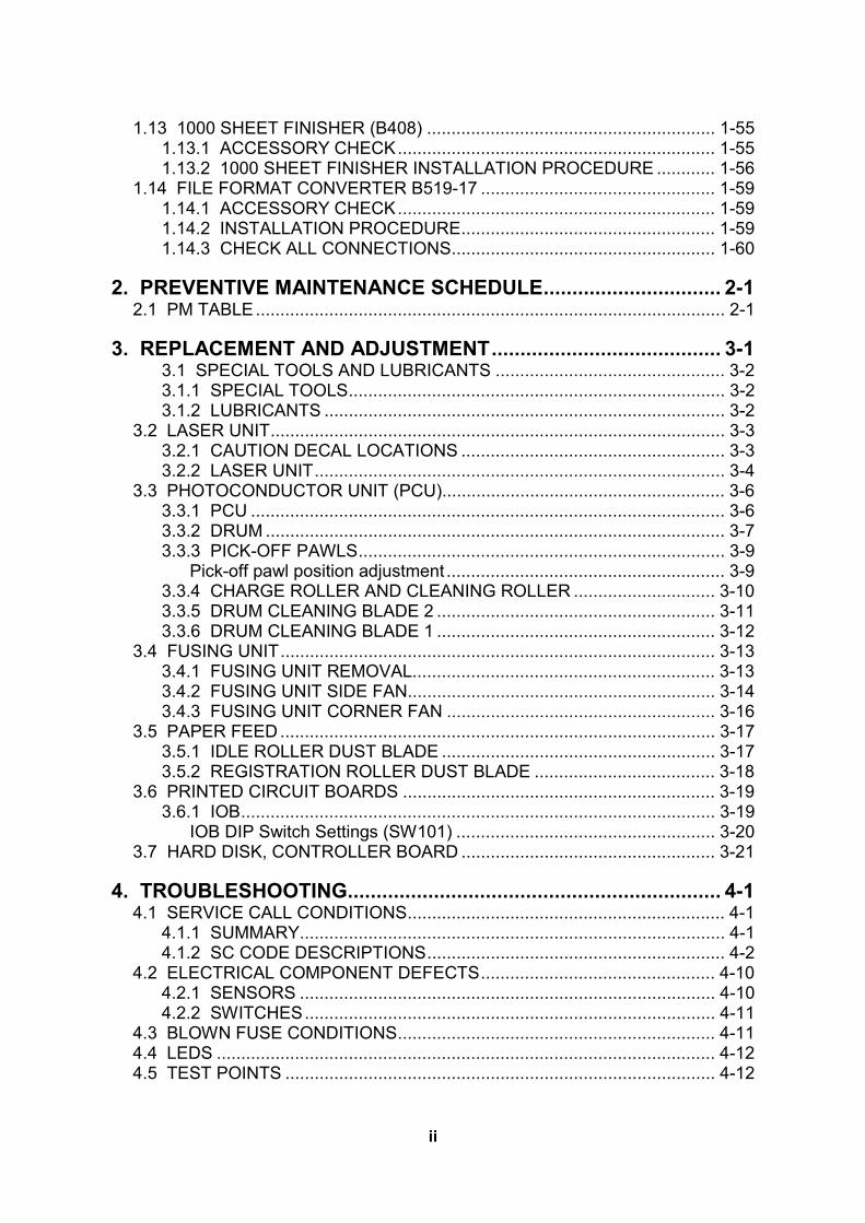
7. Spread a large piece of paper on a flat surface. NOTE: Make sure the area is free of pins, paper clips, staples, etc. to avoid
attraction to the magnetic development roller. 8. Slide the development unit [A] out and place it on the paper. 9. Remove the tape and tag [B] from the development unit 10. Remove the entrance seal plate [C] (" x 2).
B135I512.WMF
B135I105.WMF
[A]
[B]
[C]

1 August, 2003 MAIN MACHINE INSTALLATION
1-11
Inst
alla
tion
11. Remove the development roller unit [A], and set it on the paper. 12. Pour the developer [B] into the development unit.
NOTE: The developer lot number is embossed on the end of the developer package. Do not discard the package until you have recorded the lot number. (☛1-15)
1) Pour approximately 1/3 of the developer evenly along the length of the development unit.
2) Rotate the drive gear [C] to work the developer into the unit. 3) Repeat until all the developer is in the development unit. 4) Continue to turn the drive gear until the developer is even with the top of the
unit. 13. Reassemble the development unit.
NOTE: Make sure that the earth plate [D] is positioned correctly. 14. Re-install the development unit and PCU.
B135I106.WMF
B135I513.WMF
B135I019.WMF
[A]
[D]
[B]
[C]

MAIN MACHINE INSTALLATION 1 August, 2003
1-12
Toner Bottle
1. Raise the toner bottle holder lever [A], push the lever [B] to the side, and then pull the toner bottle holder [C] out.
2. Shake the new toner bottle well. NOTE: Do not remove the toner bottle cap [D] until after shaking.
3. Unscrew the bottle cap and set the bottle in the holder. NOTE: Do not touch the inner bottle cap [E].
4. Push the toner bottle holder into the main machine until it locks in place, and then lower the holder lever to secure the toner bottle. NOTE: The holder lever cannot be lowered unless the toner bottle is installed.
B135I514.WMF
[B]
[A]
[C]
[E]
[D]
1 August, 2003 MAIN MACHINE INSTALLATION
1-13
Inst
alla
tion
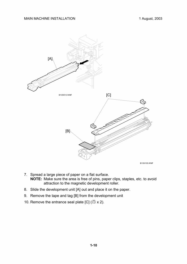
Paper Trays
1. Open the 1st paper tray, and then press down on the right side of the lock [A] switch to unlock the side fences.
2. Press in on the sides of the fence release [B], and slide the side fences [C] to the appropriate mark for the paper size.
3. Turn the dial [D] to the correct setting for the paper size. 4. Pinch the sides of the bottom fence [E] and move it to the appropriate mark for
the paper size, then load the paper. 5. Check the position of the stack.
• Confirm that there is no gap between the stack and the side fences. If you see a gap, adjust the position of the side fences.
• After loading the stack, confirm that the right side of the stack is not on top of both cushions.
B135I107.WMF
B135I109.WMF
[A] [B] [C]
[D] [E]

MAIN MACHINE INSTALLATION 1 August, 2003
1-14
6. Press down the lock [A] to lock the side fences. 7. Attach the appropriate paper size decal [B] to the paper tray. 8. Paper size decals are also used for the optional paper tray unit. Keep any
remaining decals for use with the paper tray unit. 9. Repeat this procedure to load paper in the 2nd paper tray.
B135I108.WMF
B135I110.WMF
[A]
[B]
1 August, 2003 MAIN MACHINE INSTALLATION
1-15
Inst
alla
tion
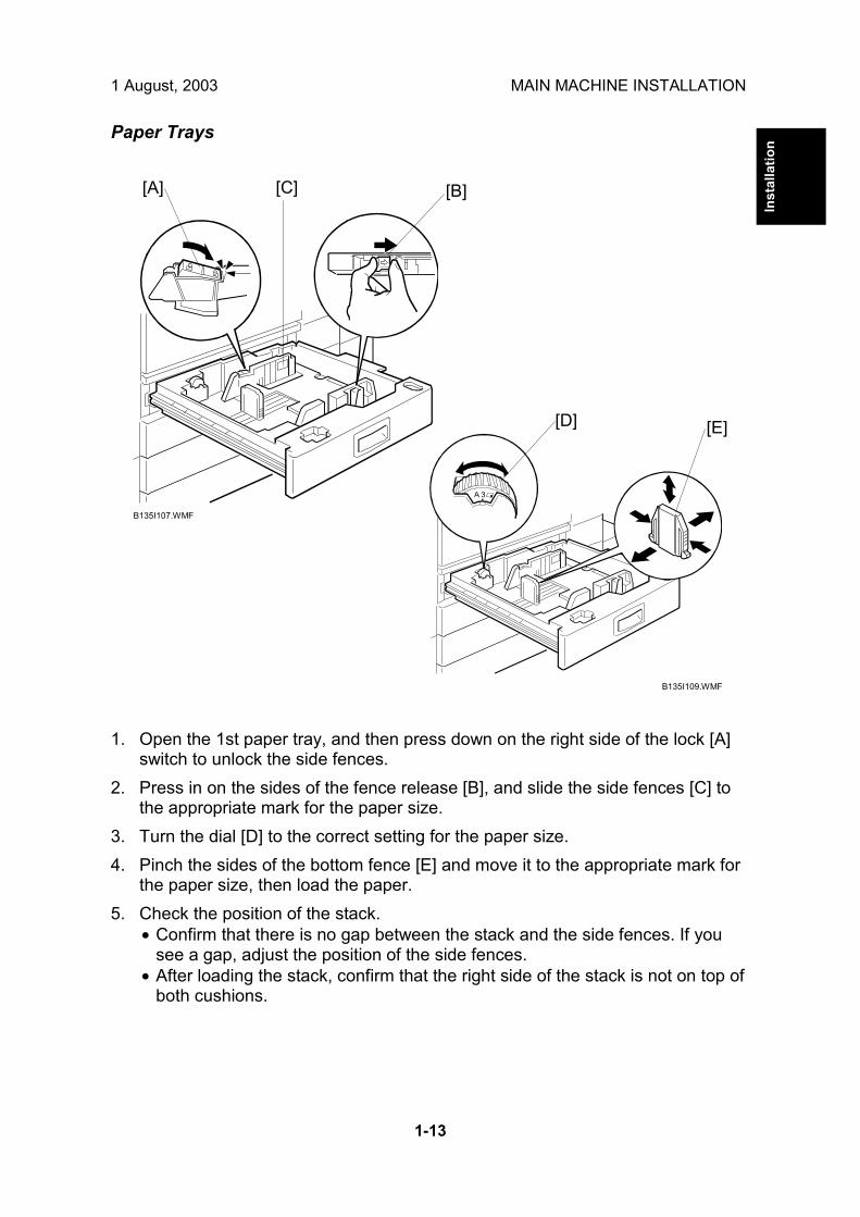
Initialize TD Sensor and Developer
1. Connect the main machine to the power outlet, switch on the main machine, and wait for the fusing unit to warm up.
2. On the operation panel, press Clear Mode ". 3. Use the number keys to enter 107. 4. Press and hold Clear/Stop # for three seconds. 5. On the touch-panel, press Copy SP. 6. Press SP Direct to highlight �SP Direct�, enter 2801, and then press $.
7. When the message prompts you to enter the lot number of the developer, enter
the 7-digit lot number, press [Yes], and then press [Execute] on the touch-panel. This initializes the TD sensor. NOTE: The lot number is printed on the end of the developer package.
Recording the lot number could help troubleshoot problems later. If the lot number is unavailable, enter any seven-digit number.
8. Press SP Direct to highlight �SP Direct� and enter 2805, press $, and then press Execute on the touch-panel. This initializes the developer.
9. Press Exit twice to return to the copy window.
B135I500.WMF

MAIN MACHINE INSTALLATION 1 August, 2003
1-16
Set Paper Size for Paper Trays
1. Press User Tools/Counter #.
2. On the touch panel, press System Settings.
3. Press the Paper Size Setting tab. 4. Press the button for the tray to change. 5. Change the setting and press the [OK] button. 6. Repeat for each tray installed. 7. Press Exit twice to return to the main display
• The 1st, 2nd, 3rd, and 4th paper trays are provided with paper size dial selectors. The dial settings on the paper trays have priority over the UP settings. However, if you select the asterisk (*) position on the paper size dial, you can select the paper size with the UP setting.
8. Check the copy quality and machine operation. NOTE: The test pattern print procedure is slightly different for this machine.
Use SP2-902 and select 2 for the IPU Test Print or 3 for the Print Test Patterns. (☛ Chapter 5, 5.1.3 Test Pattern Printing)
B135I501.WMF
B135I502.WMF

1 August, 2003 MAIN MACHINE INSTALLATION
1-17
Inst
alla
tion
Electrical Total Counter The electrical total counter no longer requires initialization. The new incrementing counter is set to �0� at the factory. NOTE: SP7825 (Total Counter Reset) remains in the Service but executing this SP
has no effect. HDD Caution Decal
1. Attach the HDD Caution decal [A] to the front cover.
Exposure Glass Cleaner
1. Attach the exposure glass cleaner holder [B] to the left side of the machine. 2. Place the exposure glass cleaner [C] inside the holder.
NOTE: The exposure glass cleaner is used to clean the ARDF exposure glass, the glass strip to the left of the large exposure glass.
10 mm (0.4")
25 mm (1.0")
B135I017.WMF
B135I018.WMF
B135I111.WMF
[B]
[C]
[A]

PAPER TRAY UNIT INSTALLATION (B542) 1 August, 2003
1-18
1.4 PAPER TRAY UNIT INSTALLATION (B542) 1.4.1 ACCESSORY CHECK
Check the quantity and condition of the accessories in the box against the following list: Description Q�ty
1. Knob Screw � M3.................................................................. 1 2. Knob Screw � M4.................................................................. 1 3. Joint Bracket ......................................................................... 1 4. Front Stand ........................................................................... 1 5. Rear Stand............................................................................ 1 6. Stand Bracket ....................................................................... 1 7. NECR.................................................................................... 1 8. Installation Procedure ........................................................... 1

1 August, 2003 PAPER TRAY UNIT INSTALLATION (B542)
1-19
Inst
alla
tion
1.4.2 PAPER TRAY UNIT INSTALLATION PROCEDURE
!CAUTION Unplug the main machine power cord before starting the following procedure.
1. Unpack the paper tray unit. 2. Remove all tape and shipping materials. 3. Remove the paper trays [A].
B542I557.WMF
B542I112.WMF
[A]

PAPER TRAY UNIT INSTALLATION (B542) 1 August, 2003
1-20
4. Remove the middle front cover [A] and pull out the front handles [B]. 5. Using the front handles and rear handles, lift the machine and hold it over the
paper tray unit [C]. 6. Slowly lower the machine onto the paper tray unit with the pegs [D] aligned with
the peg holes on the bottom of the machine. NOTE: Do not hold the scanner unit.
7. Re-install the middle front cover [A]. 8. Attach the spring washer [E] to the short knob screw [F]. Then, secure the
paper tray unit. 9. Open the right cover of the paper tray unit [G]. 10. Secure the joint bracket [H] (1 long knob screw). 11. Remove the connector cover [I] of the main machine (! x 1). 12. Connect the paper tray unit harness [J] to the main machine and reinstall the
connector cover.
B542I517.WMF
B542I113.WMF
[G]
[H]
[I]
[J]
[B]
[C]
[D]
[E]
[F]
[A]

1 August, 2003 PAPER TRAY UNIT INSTALLATION (B542)
1-21
Inst
alla
tion
13. Install the front and rear stands [A] as shown above. 14. Install the stand bracket [B].
B542I118.WMF
B542I119.WMF
[B]
[A]
[A]

PAPER TRAY UNIT INSTALLATION (B542) 1 August, 2003
1-22
15. Load paper into the paper tray and install the paper trays. 16. Attach the appropriate tray decals [A] which are included in the accessory box
for the main machine. 17. Turn on the ac switch. 18. Turn the paper size dial to the correct setting for the paper size. 19. Check the machine�s operation and copy quality.
B542I500.WMF
[A]
[A]

1 August, 2003 1-BIN TRAY UNIT INSTALLATION (B544)
1-23
Inst
alla
tion
1.5 1-BIN TRAY UNIT INSTALLATION (B544) 1.5.1 ACCESSORY CHECK
Check the quantity and condition of the accessories in the box against the following list: Description Q�ty
1. Ground Bracket..................................................................... 1 2. Connector Cover................................................................... 1 3. Base Cover ........................................................................... 1 4. Arm Cover............................................................................. 1 5. Copy Tray ............................................................................. 1 6. Mylar Strip............................................................................. 2 7. Stepped Screw � M3 x 8 ....................................................... 5 8. Screw �M3 x 8 ...................................................................... 2 9. Screw � M4 x 7 ..................................................................... 1 10. Tapping Screw � M3 x 6 ....................................................... 2 11. Tapping Screw � M3 x 14 ..................................................... 1 12. Tapping Screw � M3 x 8 ....................................................... 1 13. Installation Procedure ........................................................... 1

1-BIN TRAY UNIT INSTALLATION (B544) 1 August, 2003
1-24
1.5.2 1-BIN TRAY INSTALLATION PROCEDURE
!CAUTION Unplug the main machine power cord before starting the following procedure.
1. Remove Scanner Unit NOTE: If the ARDF is installed, remove the ARDF before removing the
scanner unit. 1) Remove the connector cover [A]. 2) Disconnect the scanner cable [B]. 3) Remove the scanner unit [C] (! x 3).
B544I114.WMF
B544I113.WMF
[C]
[A]
[B]

1 August, 2003 1-BIN TRAY UNIT INSTALLATION (B544)
1-25
Inst
alla
tion
2. Unpack the 1-bin tray unit and remove the tapes. 3. Remove the front bracket [A] (! x 1) and rear bracket [B] (! x 1) from the top
of the paper exit cover [C]. 4. Remove the paper exit cover [C] (! x 4). 5. Cut away two covers [D] from the base cover [E]. 6. Trim the edges so they are smooth. 7. Install the base cover [E] (! x 3: stepped screw). 8. Set the 1-bin tray unit [F] on the base cover and slide onto the heads of the
stepped screws.
B544I201.WMF
B544I102.WMF
[A]
[B]
[C]
[D]
[E]
[F]

1-BIN TRAY UNIT INSTALLATION (B544) 1 August, 2003
1-26
9. Secure the 1-bin tray unit [A] (! x 1 M3 x14). 10. Remove the cover [B]. 11. Install the grounding bracket [C] (! x 2 M3 x 6). 12. Connect the harness [D]. 13. Install the connector cover [E] (! x 1 M3 x 8) 14. Re-install the front bracket [F] (! x 2 M4 x 7, M4 x 10) and the rear bracket [G]
(! x 1 M4 x 10).
B544I492.WMF
B544I103.WMF
[A]
[B] [C]
[D]
[E]
[F]
[G]

1 August, 2003 1-BIN TRAY UNIT INSTALLATION (B544)
1-27
Inst
alla
tion
15. Attach the copy tray Bridge Unit (B538) has not been installed:
1) Secure [A] (stepped ! x 2) into the side of the 1-bin tray housing. 2) Attach the copy tray [B] to the stepped screws.
Bridge Unit (B538) has been installed 1) Open the cover of the bridge unit [C]. 2) First, remove the copy tray bracket [D] (" x 1). 3) Install the copy tray bracket (! x 1: tapping screw). 4) Re-install the copy tray [E] (" x 1).
B544I493.WMF
B544I501.WMF
[A]
[B]
[C] [D]
[E]

1-BIN TRAY UNIT INSTALLATION (B544) 1 August, 2003
1-28
16. Remove the scanner stand cover [A] (! x 2). 17. To adjust the height of the scanner stand, first remove [B] (! x 2) to release the
scanner stand [C]. 18. Raise the scanner stand until the next set of screw holes in the main frame can
be seen through the screw holes in the scanner stand. 19. Secure the stand (! x 2: ➀, ➁) and install the arm cover [D] (! x 1).
B544I104.WMF
B544I500.WMF
[A]
[B]
[C]
[D]

1 August, 2003 1-BIN TRAY UNIT INSTALLATION (B544)
1-29
Inst
alla
tion
20. Attach two mylar strips [A] to the scanner stand [B]. 21. Reinstall the scanner stand cover. 22. Reinstall the scanner unit. 23. Turn on the main switch and check the 1-bin tray unit operation.
B544I106.WMF[A]
[B]

BRIDGE UNIT INSTALLATION (B538) 1 August, 2003
1-30
1.6 BRIDGE UNIT INSTALLATION (B538) 1.6.1 ACCESSORY CHECK
Check the quantity and condition of the accessories in the box against the following list:
Description Q�ty
1. Stepped Screw...................................................................... 2 2. Connector Cover................................................................... 1 3. Exit Mylar .............................................................................. 2 4. Installation Procedure ........................................................... 1

1 August, 2003 BRIDGE UNIT INSTALLATION (B538)
1-31
Inst
alla
tion
1.6.2 BRIDGE UNIT INSTALLATION PROCEDURE
!CAUTION Unplug the main machine power cord before starting the following procedure.
1. Unpack the bridge unit and remove all tapes shipping retainers. 2. Remove the inner tray [A]. 3. On the side of the machine, remove the three small covers [B].
If the optional external output tray (A825) will be installed (instead of a finisher), do Step 4.
4. Remove the two small covers [C]. 5. Remove the cover [D] (! x 1). 6. Remove the cap [E].
B538I407.WMF
B538I401.WMF
B538I500.WMF
[D]
[B]
[E]
[A]
[C]

BRIDGE UNIT INSTALLATION (B538) 1 August, 2003
1-32
7. If an optional finisher is to be installed, attach two mylars [A] to the bridge unit. 8. Remove the cover [B]. 9. Install the bridge unit [C] (! x 2). 10. Connect the bridge unit I/F harnesses [D] ($ x 2). 11. Install the connector cover [E]. 12. Turn on the main switch and check the bridge unit operation (make sure that
there are no paper jams).
B538I402.WMF
B538I404.WMF
[A]
[B]
[D]
[C]
[E]

1 August, 2003 TWO-TRAY FINISHER INSTALLATION (B545)
1-33
Inst
alla
tion
1.7 TWO-TRAY FINISHER INSTALLATION (B545) 1.7.1 ACCESSORY CHECK
Check the quantity and condition of the accessories in the box against the following list: Description Q�ty
1. Front Joint Bracket ................................................................ 1 2. Rear Joint Bracket ................................................................ 1 3. Shift Tray............................................................................... 2 4. Screw � M4 x 8 ..................................................................... 2 5. Screw � M4 x 12 ................................................................... 5 6. Ground Plate......................................................................... 1 7. Installation Procedure ........................................................... 1

TWO-TRAY FINISHER INSTALLATION (B545) 1 August, 2003
1-34
1.7.2 TWO-TRAY FINISHER INSTALLATION PROCEDURE
!CAUTION Unplug the main machine power cord before starting the following procedure.
NOTE: The bridge unit (B538) and paper tray unit (B542) must be installed before installing this finisher.
1. Unpack the finisher and remove all tapes and shipping retainers from outside the unit [A].
2. Open the front door [B] and remove all tapes and shipping materials from inside the finisher unit.
3. Save the retainer [C] and other shipping material. NOTE: The retainer [C] must be re-installed in the finisher before moving or
shipping the finisher to another location.
B545I107.WMF
B545I101.WMF
[A]
[B]
[C]

1 August, 2003 TWO-TRAY FINISHER INSTALLATION (B545)
1-35
Inst
alla
tion
4. Install the left joint bracket [A] (! x 2 M4 x 12) and right joint bracket [B] (! x 2
M4 x 12). 5. Attach the ground plate [C] (! x 1 M4 x 12) to the center of the paper tray unit
as shown. 6. Open the front door of the finisher, and pull out the locking lever [D] (! x 1). 7. Push the finisher to the side of the machine with the holes in the finisher
aligned with the joint brackets, and then dock the finisher against the machine. 8. Push in the locking lever and secure it (! x 1), then close the front door.
B545I104.WMF
B545I105.WMF
[A]
[B]
[C]
[D]

TWO-TRAY FINISHER INSTALLATION (B545) 1 August, 2003
1-36
9. Install two trays [A] (! x 1 each). 10. Connect the finisher cable [B] to the main machine below the right, rear handle. 11. Turn on the main switch and check the finisher operation.
B545I103.WMF
B545I106.WMF
[A]
[B]

1 August, 2003 PUNCH UNIT INSTALLATION
1-37
Inst
alla
tion
1.8 PUNCH UNIT INSTALLATION 1.8.1 ACCESSORY CHECK
Check the quantity and condition of the accessories in the box against the following list: Description Q�ty
1. Punch unit ............................................................................. 1 2. Sensor arm ........................................................................... 1 3. Hopper .................................................................................. 1 4. Step screw ............................................................................ 1 5. Spring.................................................................................... 1 6. Spacer (2 mm) ...................................................................... 1 7. Spacer (1 mm) ...................................................................... 1 8. Tapping screw....................................................................... 1 9. Tapping screw....................................................................... 2

PUNCH UNIT INSTALLATION 1 August, 2003
1-38
1.8.2 PUNCH UNIT INSTALLATION PROCEDURE
!CAUTION Switch off the main machine and unplug its power cord. If the Two-Tray Finisher is installed, disconnect it and pull it away from the machine. (☛1.7)
1. Unpack the punch unit and remove all tapes and shipping retainers. 2. Open the front door and remove the rear cover [A] (! x4). 3. Remove the bracket [B] (! x2) and paper guide [C] (! x 1).
B377I102.WMF
B377I103.WMF
[A]
[B]
[C]

1 August, 2003 PUNCH UNIT INSTALLATION
1-39
Inst
alla
tion
4. Remove the hopper cover [A] (! x 2). 5. Install the sensor bracket [B] (stepped ! x 1). 6. Install the spring [C]. 7. Install the 2 mm spacer [D]. 8. Install the punch unit [E] (! x 2, stepped ! x 1)
B377I101.WMF
B377I104.WMF
[A]
[B]
[C]
[D]
[E]

PUNCH UNIT INSTALLATION 1 August, 2003
1-40
9. Connect the harnesses [A] and clamp them as shown. NOTE: No special DIP switch settings are required for this punch unit. The
punch unit sends an identification signal to the machine board so it knows what type of punch unit has been installed.
10. Slide the hopper [B] into the machine. 11. Fasten the two 1 mm spacers [C] to the rear frame for future adjustment.
NOTE: The spacers are used to adjust the horizontal positioning of the holes. 12. Reassemble the finisher and check the punch operation.
B377I105.WMF
B377I106.WMF
[A]
[B]
[C]

1 August, 2003 ARDF INSTALLATION (B541)
1-41
Inst
alla
tion
1.9 ARDF INSTALLATION (B541) 1.9.1 ACCESSORY CHECK
Check the quantity and condition of the accessories in the box against the following list: Description Q�ty
1. Stepped Screw...................................................................... 2 2. Screw � M4 x 10 ................................................................... 2 3. Attention Decal - Scanner ..................................................... 1 4. Attention Decal � Top Cover ................................................. 1 5. Installation Procedure ........................................................... 1
1.9.2 ARDF INSTALLATION PROCEDURE
!CAUTION Unplug the main machine power cord before starting the following procedure.
1. Unpack the ARDF and remove all tapes and shipping retainers.
B541I904.WMF

ARDF INSTALLATION (B541) 1 August, 2003
1-42
2. Attach and tighten [A] (! x 2 stud). 3. Mount the ARDF by aligning the screw keyholes [B] of the ARDF support plate
over the stud screws, and slide the ARDF toward the front of the machine. NOTE: To avoid damaging the ARDF, hold it as shown in the illustration.
4. Secure the ARDF [C] (! x 2).
5. Connect the I/F cable [D] ($ x 1) to the main machine.
B541I905.WMF
B541I124.WMF
[A]
[B]
[C]
[D]

1 August, 2003 ARDF INSTALLATION (B541)
1-43
Inst
alla
tion
6. Peel off the platen sheet [A] and place it on the exposure glass. 7. Line up the rear left corner of the platen sheet flush against corner [B] on the
exposure glass. 8. Close the ARDF. 9. Attach the decal [C] to the top cover as shown, choosing the language most
suitable for the machine installed. 10. Attach the decal [D] to the cover so that the arrow on the decal lines up with the
groove [E] of the left scale as shown. As with step 9, choose the language most suitable for the machine installed.
11. Turn on the main switch. 12. Check the ARDF operation and copy quality. Be sure to check and adjust the
registration for the ARDF with the SP modes
B541I902.WMFB541I901.WMF
B541I903.WMF
B541I906.WMF
[A]
[B]
[D]
[E]
[C]

ARDF INSTALLATION (B541) 1 August, 2003
1-44
1.9.3 ARDF SKEW ADJUSTMENT
1. Remove the tape [A] covering the elliptical hole. 2. Remove right screw [B] and install it into the elliptical hole [C]. 3. Move the right side of the ARDF forward or back to adjust the position then
tighten the screw.
B541I907.WMF
[A]
[B]
[C]

1 August, 2003 LCT INSTALLATION (B543)
1-45
Inst
alla
tion
1.10 LCT INSTALLATION (B543) 1.10.1 ACCESSORY CHECK
Check the quantity and condition of the accessories in the box against the following list: Description Q�ty
1. Joint Pin ................................................................................ 2 2. Stepped Screw M3 x 18 ........................................................ 4 3. Magnet Cover ....................................................................... 1 4. NECR (-17, -27 machines).................................................... 1 5. Installation Procedure ........................................................... 1

LCT INSTALLATION (B543) 1 August, 2003
1-46
1.10.2 LCT INSTALLATION PROCEDURE
!CAUTION Unplug the main machine power cord before starting the following procedure.
NOTE: The Paper Tray Unit (B542) must be installed before installing the LCT.
1. Unpack the LCT and remove the tapes. 2. Open the right cover of the paper tray unit [A]. 3. Open the lower right cover [B] and cut the holding band [C].
NOTE: When cutting the holding band, the upper part of the band should be cut as shown. Otherwise, paper jams may occur.
4. Remove the lower right cover.
B543I504.WMF
[C]
[B]
[A]

1 August, 2003 LCT INSTALLATION (B543)
1-47
Inst
alla
tion
6. Install the joint pins [A]. 7. Push the release lever [B] and slide the LCT to the right (front view). 8. Hang the LCT [C] on the joint pins, then secure the brackets [D] (! x 4). 9. Return the LCT to the previous position and connect the LCT cable [E]. 10. Open the LCT cover and load the paper. 11. Turn on the ac switch and check the LCT operation.
B543I503.WMF
[E]
[D][C]
[B]
[A]

PLATEN COVER INSTALLATION (G329) 1 August, 2003
1-48
1.11 PLATEN COVER INSTALLATION (G329)
1. Install [A] (! x 2) on the top cover as shown. 2. Position the platen cover bracket [B] on the heads of the stud screws and slide
the platen cover [C] to the left.
B135I904.WMF
[B][C]
[A]
[A]

1 August, 2003 BOOKLET FINISHER INSTALLATION (B546)
1-49
Inst
alla
tion
1.12 BOOKLET FINISHER INSTALLATION (B546) 1.12.1 ACCESSORY CHECK
Check the quantity and condition of the accessories in the box against the following list.
Description Q�ty
1. Upper Tray .......................................................................... 1 2. Shift Tray............................................................................. 1 3. Tapping Screw - M4 x 6 ...................................................... 2 4. Rail Ass�y ............................................................................ 1 5. Joint Bracket ....................................................................... 1 6. Tapping Screw - M4 x 16 .................................................... 8 7. Rail Bracket......................................................................... 1 8. Tapping Screw - M4 x 6 ...................................................... 1 9. Harness Cover .................................................................... 1 10. Sensor Feeler ................................................................... 1
B546I101.WMF
1
2
10
4
5
3
7
8
9
6

BOOKLET FINISHER INSTALLATION (B546) 1 August, 2003
1-50
1.12.2 BOOKLET FINISHER INSTALLATION PROCEDURE
!CAUTION Keep the power cord unplugged when starting the following procedure.
1. Unpack the finisher and remove the tapes and shipping retainers.
B546I104.WMF
B546I102.WMF

1 August, 2003 BOOKLET FINISHER INSTALLATION (B546)
1-51
Inst
alla
tion
2. Open the front under door and pull out the staple unit [A]. 3. Remove the stapler unit lock plate [B] (! x 1). 4. Push in the stapler unit and shut the front lower door. 5. Remove the right lower cover [C] (! x 4). 6. Remove the front pressure release bracket [D] (! x 1). 7. Remove the rear pressure release bracket [E] (! x 1). 8. Reattach the cover [C].
B546I105.WMF
B546I103.WMF
[C]
[E]
[A]
[B]
[D]

BOOKLET FINISHER INSTALLATION (B546) 1 August, 2003
1-52
9. Set the hooks [A] of the shift tray [B] in the notches in the shift tray bracket, and
secure the tray with two M4 x 6 screws. 10. Connect the shift tray sensor harness [C]. 11. Install the harness cover [D] (2 hooks).
B546I106.WMF
B546I107.WMF
[A] [B]
[C]
[D]

1 August, 2003 BOOKLET FINISHER INSTALLATION (B546)
1-53
Inst
alla
tion
12. Install the upper tray [A] (2 pins). 13. Attach the sensor feeler [B] (2 pins). 14. Remove the stand bracket [C]. 15. Attach the rail [D] to the rail bracket [E] as shown. 16. Install the rail bracket [F] on the left lower cover of the copier (! x 4).
B546I108.WMF
B546I921.WMF
B546I801.WMF
[A]
[B]
[D][E]
[F]
[C]

BOOKLET FINISHER INSTALLATION (B546) 1 August, 2003
1-54
17. Install the joint bracket [A] on the left side of the copier (! x 4). 18. Secure the rail [B] to the booklet finisher with 1 M4 screw. 19. Align the finisher on the joint bracket and lock the 2 hooks [C] of the finisher on
the joint bracket. 20. Connect the finisher cable [D] to the copier. 21. Turn on the main switch and check the finisher operation.
B546I920.WMF
B546I111.WMF
[A]
[B]
[C][D]

1 August, 2003 1000 SHEET FINISHER (B408)
1-55
Inst
alla
tion
1.13 1000 SHEET FINISHER (B408) 1.13.1 ACCESSORY CHECK
Check the quantity and condition of the accessories against the following list.
Description Q�ty
1 Front Joint Bracket............................................................... 1 2 Rear Joint Bracket *1 ............................................................ 1 3 Rear Joint Bracket ............................................................... 1 4 Grounding Plate ................................................................... 1 5 Copy Tray ............................................................................ 1 6 Staple Position Decal........................................................... 1 7 Screw - M4 x 14 ................................................................... 4 8 Knob Screw - M4 x 10.......................................................... 1 9 Screw - M3 x 8 ..................................................................... 1 10 Knob Screw - M3 x 8.......................................................... 1
*1: Rear joint bracket is not required for these models.
B408I502.WMF
1 2
3
4
5 8
9
6 7
10

1000 SHEET FINISHER (B408) 1 August, 2003
1-56
1.13.2 1000 SHEET FINISHER INSTALLATION PROCEDURE
!CAUTION Unplug the main machine power cord before starting the following procedure.
1. The following options must be installed before installing this finisher. - Bridge Unit (B538) - Paper Tray Unit (B542)
2. Unpack the finisher and remove the tapes. NOTE: Be sure to keep screw [A]. It will be needed to secure the grounding
plate in Step 3.
B408I102.WMF
B408I103.WMF
[A]

1 August, 2003 1000 SHEET FINISHER (B408)
1-57
Inst
alla
tion
2. Install the front joint bracket [A] (2 screws - M4 x 14) and rear joint bracket [B] (! x 2 M4 x 14).
3. Install the grounding plate [C] to the finisher (! x 2 M3 x 8). NOTE: Use the screw removed in step 1 and the screw from the accessory
box. 4. Open the front door [D] then pull the locking lever [E]. 5. Align the finisher on the joint brackets, and lock it in place by pushing the
locking lever. 6. Secure the locking lever (! x 1 knob screw M3 x 8). 7. Close the front door. 8. Install the copy tray [F] (! x 1 knob screw M4 x 10). 9. Connect the finisher cable [G] to the main machine below the right rear handle.
B408I503.WMF
B408I201.WMF
B408I504.WMF
[A]
[B]
[C]
[D]
[E]
[F]
[G]

1000 SHEET FINISHER (B408) 1 August, 2003
1-58
10. Attach the staple position decal [A] to the ARDF as shown. 11. Turn on the main power switch and check the finisher operation.
B408I501.WMF
[A]

1 August, 2003 FILE FORMAT CONVERTER B519-17
1-59
Inst
alla
tion
1.14 FILE FORMAT CONVERTER B519-17 1.14.1 ACCESSORY CHECK
1. File Format Converter Board ......................................... 1 1.14.2 INSTALLATION PROCEDURE
!CAUTION Switch the machine off and unplug the main machine power cord before starting the following procedure.
1. Remove the left corner cover (! x 2). 2. Remove the rear upper cover (! x 2). 3. Remove the rear lower cover (! x 4). 4. Remove the controller box [A] (! x 2). 5. Remove the two screws [B] from the controller board. 6. Use the screws removed in the previous step to attach the File Format
Converter board [C] to the controller board [D] (! x 2) 7. Reattach the controller box and covers.
B519I502.WMF
B519I501.WMF
[B]
[D]
[A]
[C]

FILE FORMAT CONVERTER B519-17 1 August, 2003
1-60
1.14.3 CHECK ALL CONNECTIONS
1. Plug in the power cord and turn on the main switch. 2. Enter the printer user mode and print the configuration page.
User Tools> Printer Settings> List Test Print> Config. Page
NOTE: The same data can also be printed by executing SP1-004 � Print Summary. All installed options are listed in the �System Reference� column.

1 August, 2003 PM TABLE
2-1
Prev
entiv
eM
aint
enan
ce
2. PREVENTIVE MAINTENANCE SCHEDULE 2.1 PM TABLE NOTE: Amounts mentioned as the PM interval indicate the number of prints.
Symbol key: C: Clean, R: Replace, L: Lubricate, I: Inspect
B135/B138 EM 150K 300K 450K NOTE SCANNER/OPTICS Reflector C C C Optics cloth 1st Mirror C C C Optics cloth 2nd Mirror C C C Optics cloth 3rd Mirror C C C Optics cloth Scanner Guide Rails I I I Do not use alcohol. Lubricate
if necessary. Platen Sheet Cover C I I I Dry cloth or alcohol. Replace
platen sheet if required. Exposure Glass C C C Dry cloth or alcohol Toner Shield Glass C C C Optics cloth APS Sensor C C C Dry cloth or alcohol Exposure Glass (Sheet through) C C C Dry cloth or alcohol
DRUM (OPC) AREA Charge Roller R R R Charge Roller Cleaning Roller R R R
Drum Cleaning Blade 1 R R R Drum Cleaning Blade 2 R R R Quenching Lamp C Dry cloth Pick-off Pawls R R R Spurs C C C Dry cloth or alcohol ID Sensor C C C Perform SP3-001-2 after
blower brush cleaning. Cleaning Entrance Seal C C C Blower brush. Replace if
required. Side Seal I I I

PM TABLE 1 August, 2003
2-2
B003/B004B006/B007 EM 150K 300K 450K NOTE
DEVELOPMENT UNIT Development Drive Gears I I I
Development Filter R R R Developer I R I Entrance Seal I I I Side Seal I I I Development Roller C C C Dry cloth PAPER FEED Registration Roller C C C C Water or alcohol. Idle Roller Dust Blade
C C C Detach and tap gently on flat surface to empty. Blower brush.
Registration Roller Dust Blade C R C Blower brush.
Paper Feed Roller I R R R Separation Roller I R R R Pick-up Roller I R R R Paper Feed Roller (By-pass feed table) I R R R
Separation Roller (By-pass feed table) I R R R
Pick-up Roller (By-pass feed table) I R R R
Check counter value for each (SP7-204). If ≥ 150 K, replace roller. After replacing the roller, do SP7-816 to reset counter.
Paper Feed Guides C C C Water or alcohol. Relay Rollers C C C Water or alcohol. Bottom Plate Pad C C C Water or alcohol. Bottom Plate Pad (By-pass feed) C C C Water or alcohol.
Registration Sensor C C C Blower brush Paper Feed Roller Gear L L L Silicone Grease G-501. See
note below.*1 Upper Relay Sensor C C C Blower Brush DUPLEX UNIT Upper Transport Roller C C C Water or alcohol. Lower Transport Roller C C C Water or alcohol. TRANSFER BELT UNIT Transfer Belt C R R R Dry cloth Transfer Belt Cleaning Blade R R R
Transfer Belt Rollers C C C Dry cloth Entrance Seal C C C Dry cloth Transfer Entrance Guide C C C C Dry cloth
Used Toner Tank I C C C Empty the tank.

1 August, 2003 PM TABLE
2-3
Prev
entiv
eM
aint
enan
ce
B135/B138 EM 150K 300K 450K NOTE
FUSING UNIT AND PAPER EXIT Fusing Entrance and Exit Guide Plates C C C Water or alcohol.
Hot Roller R R R Pressure Roller R R R Fusing Thermistors R R R Cleaning Roller R R R Cleaning Roller Bushings L L L Grease: Barrierta JFE 55/2
Hot Roller Strippers C R C Water or alcohol. Paper Exit Guide Ribs C C C Water or alcohol. (See
illustration below.) Exit Sensor C C C Blower brush DRIVE Drive Belts I Replace if necessary
B541 EM 80K 160K 240K NOTE
ARDF (for originals) Pick-up Roller C R R R Belt cleaner Feed Belt C R R R Belt cleaner Separation Roller C R R R Dry or damp cloth Sensors C C C Blower brush Drive Gears L L L Grease, G501
B542 EM 150K 300K 450K NOTE
PAPER TRAY UNIT Paper Feed Rollers R R R Pick-up Rollers R R R Separation Rollers R R R
Check counter with SP7-204. If ≥ 150 K, replace roller. After replacing the roller, do SP7-816 to reset counter.
Relay Rollers C C C Dry or damp cloth Bottom Plate Pad C C C Dry or damp cloth
B135P901.WMF
Clean here.

PM TABLE 1 August, 2003
2-4
B543 EM 150K 300K 450K NOTE
LCT Paper Feed Roller
R R R
Check counter with SP7-204. If ≥ 150 K, replace roller. After replacing the roller, do SP7-816 to reset counter.
Pick-up Roller R R R Separation Roller R R R
Bottom Plate Pad C C C Dry or damp cloth
B408/B545 EM 150K 300K 450K NOTE 1000-SHEET/TWO-TRAY FINISHER Rollers C Water or alcohol. Brush Roller (A681 only) I I I I Replace if required.
Discharge Brush C C C C Dry cloth Sensors C Blower brush Jogger Fences I I I I Replace if required. Punch Waste Hopper* I I I I Empty hopper.
*: Only for B545
B546 EM 150K 300K 450K NOTE BOOKLET FINISHER Transport Belt C C C Stapler Paddles C C C
B544 EM 150K 300K 450K NOTE
1-BIN TRAY UNIT Rollers C Dry or damp cloth Copy Tray C Dry or damp cloth Sensors C Blower brush
*1: Lubricate the paper feed clutch gear [A]
with Silicone Grease G501 every P.M.
B135P900.WMF
[A]
1 August, 2003 SPECIAL TOOLS AND LUBRICANTS
3-1
Rep
lace
men
tA
djus
tmen
t
3. REPLACEMENT AND ADJUSTMENT New design changes have been implemented in order to accommodate the new PxP (Polyester Polymerization) toner, which is of smaller particle size and allows lower fusing temperatures. This section describes some of these design changes and how they affect replacement and adjustment procedures. PCU • New cleaning blade: The PCU (Photoconductor Unit) must handle finer toner,
so in addition to the stationary drum cleaning blade, a spring-loaded blade has been added for drum cleaning. The additional cleaning blade is required for the finer toner, and a new procedure for removal has been added. (☛ Drum Cleaning Blade)
• Charge roller replacement: The standard voltages for SP2001 1 have changed and must be checked after charge roller replacement.
Fusing Unit The fusing unit can be operated at a lower temperature for the finer toner because it melts easily, so the following changes have been made in the fusing unit: • Cooling fans: Two cooling fans have been added around the fusing unit, one on
the right side of the machine and another on the right corner. Two new removal procedures have been added. (☛ 3.4.2, 3.4.3)
• Hot roller knob: The size of the knob on the end of the fusing unit is larger, making the roller easier to turn manually. (☛ 3.4.1)
Other Changes While the following are not related to the new toner, they are nonetheless important changes: • Toner shield glass cover: The shield glass is now equipped with a cover that
locks the glass in place and prevents the shield glass from sliding out of the machine accidentally. (☛ 3.2.2)
• Dust blades: Two new paper dust blades have been added around the registration roller to clean paper dust from the paper feed path. Both blades can be easily removed and cleaned. (☛ 3.5.1, 3.5.2)
• IOB: The IOB (I/O Interface Board) has been moved from inside the machine to under the rear lower cover, making access much easier. (☛ 3.6.1)
• Flash memory cards: The number designations for the flash memory cards have changed. (☛3.1.1)

SPECIAL TOOLS AND LUBRICANTS 1 August, 2003
3-2
3.1 SPECIAL TOOLS AND LUBRICANTS 3.1.1 SPECIAL TOOLS
Part Number Description Q�ty A2309003 Adjustment Cam � Laser Unit 1 A2309004 Positioning Pin � Laser Unit 1 N8036701 Flash Memory Card � 4MB 1 N8031000 Case � Flash Memory Card 1 A0069104 Scanner Positioning Pin (4 pcs/set) 1 A2929500 Test Chart � S5S (10 pcs/Set) 1 G0219350 Parallel Loopback Connector 1
3.1.2 LUBRICANTS
Part Number Description Q�ty A2579300 Grease Barrierta S552R 1 52039502 Silicone Grease G-501 1

1 August, 2003 LASER UNIT
3-3
Rep
lace
men
tA
djus
tmen
t
3.2 LASER UNIT
!WARNING Turn off the main power switch and unplug the machine before attempting any of the procedures in this section. Laser beams can seriously damage your eyes.
3.2.1 CAUTION DECAL LOCATIONS
Two caution decals are located in the laser section as shown below. (See the next page for removal instructions.)
A232R500.CDR
LASER-1.WMF LASER-3.WMF
LASER-2.WMF

LASER UNIT 1 August, 2003
3-4
3.2.2 LASER UNIT
!WARNING Turn off the main power switch and unplug the machine before attempting this procedure. Laser beams can seriously damage your eyes.
1. Open the front door and raise the toner bottle holder handle [A]. 2. Front door (pins [B] x 2) 3. Inner cover [C] (! x 2, " x 1) 4. Shield glass cover [D].
The shield glass cover holds the shield glass firmly in place and prevents it from accidental removal. To remove, on the left side press in the top leaf and pull off. When re-attaching the shield glass cover, note that the top leaf lies on top of the plastic form.
5. Shield glass [E]
B135R901.WMF
[A] [C]
[B]
[D]
[E] [B]

1 August, 2003 LASER UNIT
3-5
Rep
lace
men
tA
djus
tmen
t
6. Shield plate [A] (! x 2) 7. Laser unit connectors [B] (" x 6, " x1 flat cable)
NOTE: Hold the LD board securely when disconnecting connectors. 8. Laser unit [C] (! x 2)
NOTE: When sliding out the laser unit, do not hold the LD board. Hold the laser unit casing.
B135R902.WMF[A]
[B]
[C]

PHOTOCONDUCTOR UNIT (PCU) 1 August, 2003
3-6
3.3 PHOTOCONDUCTOR UNIT (PCU) 3.3.1 PCU
1. Open the front door. 2. Lower the by-pass tray, open the duplex unit, and open the transfer unit right
cover. 3. Spread a sheet of A4 or LTR size paper [A] on top of the open front door.
NOTE: This paper catches any loose toner that may fall from the PCU as it is removed.
4. Loosen [B] (! x 1). 5. Rotate bracket [C] to the left. 6. Raise the release lever [D]. 7. Hold the PCU [E] as shown and pull it out of the machine.
NOTE: If the right cover is to be left open, cover the drum with paper, or remove the PCU and cover it with paper. Before you re-install the PCU, align the brackets on the PCU with the rails above and make sure they are engaged before you slowly push the PCU into the machine.
B135R903.WMF
B135R904.WMF
[A]
[B]
[C]
[D]
[E]
1 August, 2003 PHOTOCONDUCTOR UNIT (PCU)
3-7
Rep
lace
men
tA
djus
tmen
t
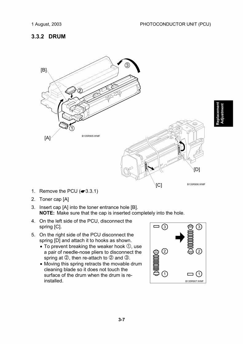
3.3.2 DRUM
1. Remove the PCU (☛3.3.1) 2. Toner cap [A] 3. Insert cap [A] into the toner entrance hole [B].
NOTE: Make sure that the cap is inserted completely into the hole. 4. On the left side of the PCU, disconnect the
spring [C]. 5. On the right side of the PCU disconnect the
spring [D] and attach it to hooks as shown. • To prevent breaking the weaker hook ➀, use
a pair of needle-nose pliers to disconnect the spring at ➁, then re-attach to ➁ and ➂.
• Moving this spring retracts the movable drum cleaning blade so it does not touch the surface of the drum when the drum is re-installed.
B135R905.WMF
B135R906.WMF
1
2
3
1
2
3
B135R907.WMF
[A]
[B]
[C]
[D]

PHOTOCONDUCTOR UNIT (PCU) 1 August, 2003
3-8
6. Turn the PCU upside-down, and remove lower PCU cover [A] (! x 2, 3 pawls). 7. Pull the drum [B] towards the front ➁ (the left side in the illustration) while
releasing the charge roller [C] using the release lever ➀ [D], and then remove the drum ➂. CAUTION: Never touch the drum surface with bare hands.
8. Replace the drum and re-attach the lower PCU cover.
9. Detach the spring from ➁, ➂and re-attach to ➀, ➁.
CAUTION: You must return re-attach the spring to ➀, ➁ in order for the cleaning blade to operate correctly.
If you fail to re-attach the spring to ➀, ➁ the movable cleaning blade will not contact the drum for cleaning, but the machine will operate without generating an error. However, copies will gradually become dirty due to toner collecting on the drum.
10. Re-attach the spring on the left side of the PCU. 11. After replacing the drum, perform the ID sensor initial setting using SP3001
002. 12. Do the process initial setting procedure (SP2805).
B135R908.WMF
B135R909.WMF
1
2
3
1
2
3
B135R910.WMF
[A]
[B]
[C] [D]

1 August, 2003 PHOTOCONDUCTOR UNIT (PCU)
3-9
Rep
lace
men
tA
djus
tmen
t
3.3.3 PICK-OFF PAWLS
1. Remove the drum. (☛ 3.3.2) 2. Pawl assembly [A] 3. Pick-off pawl [B] (spring x 1, spur x 1) Pick-off pawl position adjustment If the pick-off pawl has marked the drum with a line, the pick-off pawl position can be adjusted using either method: • Changing the spur position. • Changing the pick-off pawl assembly position CAUTION: After re-assembly make sure that the front spring of the movable
cleaning blade is re-attached to the ➀, ➁ position. (☛ 3.3.2)
B135R911.WMF
[A]
[B]

PHOTOCONDUCTOR UNIT (PCU) 1 August, 2003
3-10
3.3.4 CHARGE ROLLER AND CLEANING ROLLER
1. Remove the drum. (☛ 3.3.2) 2. Two snap rings [A] (# x 2). 3. Push charge roller holder [B] toward the front of the PCU and remove the
spring [C]. 4. Charge roller [D].
NOTE: Disengage the charge roller on the right side to remove. Try to avoid touching the charge roller.
5. Cleaning roller [E]. NOTE: Disengage the cleaning roller on the left to remove.
6. After replacing the charge roller and cleaning roller, check the value of SP2001 001. If it is not at the standard value (1450 V), set SP2001 001 to �1450 V. NOTE: If this is not done, the carrier will be attracted to the drum because the
charge roller voltage will be too high. CAUTION: After re-assembly make sure that the front spring of the movable
cleaning blade is re-attached to the ➀, ➁ position. (☛ 3.3.2)
B135R912.WMF
[A]
[B]
[C]
[D]
[E]

1 August, 2003 PHOTOCONDUCTOR UNIT (PCU)
3-11
Rep
lace
men
tA
djus
tmen
t
3.3.5 DRUM CLEANING BLADE 2
1. Remove the OPC drum. (☛ 3.3.2) 2. Remove the charge roller and cleaning roller. (☛ 3.3.4) 3. Remove the movable cleaning blade [A]. (# x 1) Re-installation • Engage the left end of the cleaning blade first, then make sure that both arms [B]
and [C] are through the holes on the left and right side. • When you re-attach the snap-ring, make sure that the head of the snap ring [D] is
below the blade. CAUTION: After re-assembly make sure that the front spring of the movable
cleaning blade is re-attached to the ➀, ➁ position. (☛ 3.3.2)
B135R913.WMF
[A]
[B]
[C]
[D]

PHOTOCONDUCTOR UNIT (PCU) 1 August, 2003
3-12
3.3.6 DRUM CLEANING BLADE 1
1. Remove the drum. (☛ 3.3.2) 2. Remove the charge roller and cleaning roller. (☛ 3.3.4) 3. Remove the movable cleaning blade. (☛ 3.3.5) 4. Remove the stationary drum cleaning blade [A] (! x 2) CAUTION: After re-assembly make sure that the front spring of the movable
cleaning blade is re-attached to the ➀, ➁ position. (☛ 3.3.2)
B135R929.WMF
[A]

1 August, 2003 FUSING UNIT
3-13
Rep
lace
men
tA
djus
tmen
t
3.4 FUSING UNIT
!CAUTION Allow time for the unit to cool before doing the following procedure.
3.4.1 FUSING UNIT REMOVAL
1. Open the front door, duplex unit, and right door. 2. Set screw [A] (! x 1) 3. Fusing unit release lever [B] 4. Slide out the fusing unit [C] NOTE: A larger knob [D] is provided to make turning the hot roller easier to free
jams.
B135R915.WMF
[A]
[B]
[C]
[D]

FUSING UNIT 1 August, 2003
3-14
3.4.2 FUSING UNIT SIDE FAN
1. Open the duplex unit and right door. 2. Release the transfer unit [A] and remove it. 3. Remove the shaft cover [B] (! x 3).
B135R916.WMF
B135R917.WMF
[A]
[B]
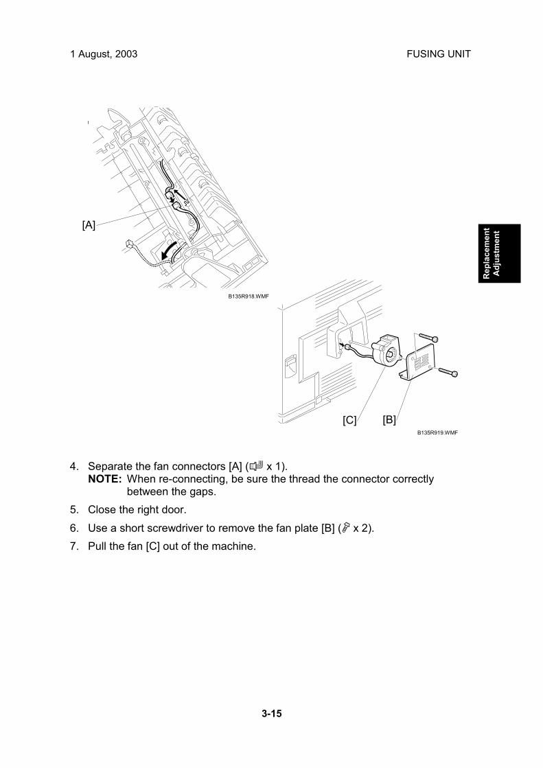
1 August, 2003 FUSING UNIT
3-15
Rep
lace
men
tA
djus
tmen
t
4. Separate the fan connectors [A] (" x 1). NOTE: When re-connecting, be sure the thread the connector correctly
between the gaps. 5. Close the right door. 6. Use a short screwdriver to remove the fan plate [B] (! x 2). 7. Pull the fan [C] out of the machine.
B135R918.WMF
B135R919.WMF
[A]
[B] [C]

FUSING UNIT 1 August, 2003
3-16
3.4.3 FUSING UNIT CORNER FAN
1. Open the front door. 2. Open the duplex unit and right door. 3. Remove the fusing unit. (☛ 3.4.1) 4. Remove the magnet lock [A] of the front door (! x 2). 5. Remove the fan bracket [B] (! x 2). 6. Remove the fan [C] from the bracket (! x 2).
B135R920.WMF
B135R921.WMF
[A]
[B]
[C]
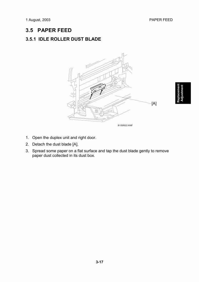
1 August, 2003 PAPER FEED
3-17
Rep
lace
men
tA
djus
tmen
t
3.5 PAPER FEED 3.5.1 IDLE ROLLER DUST BLADE
1. Open the duplex unit and right door. 2. Detach the dust blade [A]. 3. Spread some paper on a flat surface and tap the dust blade gently to remove
paper dust collected in its dust box.
B135R922.WMF
[A]

PAPER FEED 1 August, 2003
3-18
3.5.2 REGISTRATION ROLLER DUST BLADE
1. Open the duplex unit and open the right door. 2. Remove the PCU. (☛3.3.1) 3. Remove the development unit [A]. 4. Press the top of the blade [B] to unlock it and open it to the left. 5. Remove the dust blade [C] from the machine.
B135R923.WMF
B135R924.WMF
[B]
[C]
[A]

1 August, 2003 PRINTED CIRCUIT BOARDS
3-19
Rep
lace
men
tA
djus
tmen
t
3.6 PRINTED CIRCUIT BOARDS 3.6.1 IOB
1. Remove the rear lower cover [A] (! x 4). 2. Remove the IOB [B] (" All, ! x 4, Ribbon cable x 1). 3. The IOB is identical for the B135/B138. However, the DIP switches are set
differently for each machine. Check the DIP switches then adjust settings as required. (See next page.)
B135R925.WMF
B135R926.WMF
[A]
[B]

PRINTED CIRCUIT BOARDS 1 August, 2003
3-20
IOB DIP Switch Settings (SW101)
1. The position of SW 1 determines the engine speed. This switch should be UP (ON) for the B135 (35 cpm) or DOWN (OFF) for the B138 (45 cpm) NOTE: Move a switch UP to ON or DOWN to OFF.
2. SW 2, 3, 4, and 5 should all be DOWN (OFF). Do not change these settings. This information is only for reference:
SW If set to ON 2 Switches off jam detection. 3 Engine program recovery. 4 Print output for debugging. 5 Checking duplex function at the factory.
3. SW 6, 7, 8 should be set for the area where the machine is used and serviced.
6 7 8 Location OFF OFF OFF Japan ON OFF OFF North America OFF ON OFF Europe OFF OFF ON China ON OFF ON Taiwan ON ON OFF Asia OFF ON ON Korea ON ON ON Not used
ON: Up OFF: Down

1 August, 2003 HARD DISK, CONTROLLER BOARD
3-21
Rep
lace
men
tA
djus
tmen
t
3.7 HARD DISK, CONTROLLER BOARD NOTE: The controller boards are machine specific, i.e. the controller board for the
B135 (35 cpm) must be installed in the B135 copier, and the controller board for the B138 (45 cpm) must be installed in the B138 copier. These controller boards are not interchangeable.
1. Controller board [A] (! x 2) NOTE: Use the wire handle to slide the HDD out of the expansion box.
2. HDD unit bracket [B] (! x 3, " x 2) 3. HDD unit [C] (! x 4)
NOTE: Work carefully to avoid dropping or hitting the HDD. After replacing the HDD, execute SP 5853 to copy the stamp data from the firmware ROM to the new disk. No flash card is needed.
B135R927.WMF
B135R928.WMF
[B]
[C]
[A]

1 August, 2003 SERVICE CALL CONDITIONS
4-1
Trou
ble-
shoo
ting
4. TROUBLESHOOTING !CAUTION Never turn off the main power switch when the power LED is lit or flashing. To avoid damaging the hard disk or memory, press the operation power switch to switch the power off, wait for the power LED to go off, and then switch the main power switch off.
NOTE: The main power LED lights or flashes while the platen cover or ARDF is
open, while the main machine is communicating with a facsimile or the network server, or while the machine is accessing the hard disk or memory for reading or writing data.
4.1 SERVICE CALL CONDITIONS 4.1.1 SUMMARY
There are 4 levels of service call conditions.
Level Definition Reset Procedure
A
To prevent damage to the machine, the main machine cannot be operated until the SC has been reset by a service representative (see the note below).
Enter SP mode, and then turn the main power switch off and on.
B If the SC was caused by incorrect sensor detection, the SC can be reset by turning the main power switch off and on.
Turn the operation switch and main power switch off and on.
C The main machine can be operated as usual, excluding the unit related to the service call.
Turn the operation switch off and on.
D The SC history is updated. The machine can be operated as usual.
The SC will not be displayed. Only the SC history is updated.
NOTE: 1) If the problem concerns electrical circuit boards, first disconnect then reconnect the connectors before replacing the PCBs.
2) If the problem concerns a motor lock, first check the mechanical load before replacing motors or sensors.

SERVICE CALL CONDITIONS 1 August, 2003
4-2
4.1.2 SC CODE DESCRIPTIONS NOTE: This is a list of the new and revised SC codes for the B135 (35 cpm) and
B138 (45 cpm) machines. For details about other SC codes please refer to Service Manual of the previous models.
Code No. Symptom Possible Cause 320 C Polygon motor error
(Deleted)
Polygonal Mirror Motor Error 1: ON Timeout
335 (New)
C
The XSCRDY signal is not issued (LOW: Active) within 25 s after the polygonal mirror motor switches on.
• I/F harness of the polygonal mirror motor disconnected or defective.
• Polygonal mirror motor or polygonal mirror motor driver defective.
• Polygonal mirror motor drive pulse is not output incorrectly.
• GABIC cannot monitor XSCRDY signal.
Polygonal Mirror Motor Error 2: OFF Timeout
336 (New)
C
The XSCRDY signal is not issued (HIGH: Inactive) within 2 s after the polygonal mirror motor switches off.
• I/F harness of the polygonal mirror motor disconnected or defective.
• Polygonal mirror motor or polygonal mirror motor driver defective.
• Polygonal mirror motor drive pulse is not output incorrectly.
• GABIC cannot monitor XSCRDY signal.
Polygonal Mirror Motor Error 3: XSCRDY Signal Error
337 (New)
C
The XSCRDY is not issued (HIGH: Inactive) after the polygonal mirror motor has been rotating normally for 600 ms.
• I/F harness of the polygonal mirror motor disconnected or defective.
• Polygonal mirror motor or polygonal mirror motor driver defective.
• Polygonal mirror motor drive pulse is not output incorrectly.
• GABIC cannot monitor XSCRDY signal.
Polygonal Mirror Motor Error 4: Unstable Timeout
338 (New)
C
The XSCRDY signal is detected LOW) (Active) after the polygonal mirror motor switches on, but the signal is not detected LOW after 1 s has elapsed, and not detected after another 500 ms has elapsed.
• I/F harness of the polygonal mirror motor disconnected or defective.
• Polygonal mirror motor or polygonal mirror motor driver defective.
• Polygonal mirror motor drive pulse is not output incorrectly.
• GABIC cannot monitor XSCRDY signal.
450 Feed Development Motor Error (New)
C The PLL lock signal remains LOW for 2 s while the feed development motor is operating.
• Motor lock caused by overload. • Motor driver defective.
520 Fusing/Feed-Out Motor Error (New)
C The PLL lock signal remains LOW for 2 s while the feed development motor is operating.
• Motor lock caused by overload. • Motor driver defective.

1 August, 2003 SERVICE CALL CONDITIONS
4-3
Trou
ble-
shoo
ting
Code No. Symptom Possible Cause
Booklet finisher error in finisher area 01 Shutter movement error 1) The shutter position switch does
not turn on within 1 second after the transport motor starts to turn in reverse.
2) The shutter sensor does not deactivate within 1 second after the transport motor starts to turn in reverse.
3) The shutter position switch is off when the shift tray safety switch is off.
• Transport motor defective • Shutter position switch defective • Shift tray safety switch defective
Exit motor error 02 1) After the exit motor turns on, the
exit motor sensor does not send the proper signal to the finisher board.
2) The exit motor sensor does not send the clock signal to the finisher board for certain period while the exit motor is on.
• Exit motor defective • Exit motor sensor defective
Upper exit plate movement error 03 1) The upper exit guide 2 switch
does not turn on within 1s after the guide plate motor turns on.
2) The upper exit guide sensor does not activate within 1s after the guide plate motor turns on.
3) The upper exit guide 2 switch does not turn on when the shift tray safety switch is off.
• Guide plate motor defective • Upper exit guide 2 switch
defective • Upper exit guide sensor
defective • Shift tray safety switch defective
Jogger motor error
740 D
04 1) After the jogger motor turns on to
move the jogger fence from its home position, the jogger HP sensor does not deactivate within 2s.
2) After the jogger motor turns on to return the jogger fence to its home position, the jogger HP sensor does not activate within 2s.
• Jogger motor defective • Jogger HP sensor defective

SERVICE CALL CONDITIONS 1 August, 2003
4-4
Code No. Symptom Possible Cause Stapler motor error 05 1) After the stapler motor turns on to
move the stapler unit from its home position, the stapler unit HP sensor does not deactivate within 4s.
2) After the stapler motor turns on to return the stapler unit to its home position, the stapler unit HP sensor does not activate within 4s.
• Stapler motor defective • Stapler unit HP sensor defective
Staple hammer motor error 06 1) The staple hammer HP sensor
does not deactivate within 0.5s after the staple hammer motor turns on.
2) The staple hammer HP sensor does not activate within 0.5s after the staple hammer motor turns on.
• Staple hammer motor defective • Staple hammer HP sensor
defective
Tray lift motor error 07 1) The tray lift motor does not stop
within 15s after being turned on. 2) The shift tray HP sensor does not
activate within 15s after the tray lift motor turns on.
3) The shift tray upper limit switch turns on while the shift tray is being raised.
4) Lift motor sensors 1 & 2 do not send the clock signals to the finisher board every 200ms while the tray lift motor is on.
• Tray lift motor defective • Lift motor sensor 1 defective • Lift motor sensor 2 defective • Shift tray HP sensor defective • Shift tray upper limit switch
defective
Shift tray height sensor error 08 1) Abnormal communication data
between finisher board and shift tray height sensor.
2) No communication between finisher board and shift tray height sensor for a certain period.
3) The finisher board detects a connection error with the connector for the shift tray height sensor.
4) Adjustment error during shift tray height sensor adjustment.
• Shift tray height sensor defective • Finisher board defective
Back-up RAM error
D
09 The check sum is abnormal when the main switch is turned on.
• Finisher board defective

1 August, 2003 SERVICE CALL CONDITIONS
4-5
Trou
ble-
shoo
ting
Code No. Symptom Possible Cause Communication error 740 D 10
Communication error between finisher board and booklet unit board.
• Finisher board defective • Booklet unit board defective • Poor connection of the interface
harness Booklet finisher error in saddle stitching area
01 Positioning plate motor error 1) After the positioning plate
motor turns on to move the positioning plate from its home position, the positioning plate HP sensor does not deactivate within 1.25s.
2) After the positioning plate motor turns on to return the positioning plate to its home position, the positioning plate HP sensor does activate within 1s.
• Positioning plate motor defective• Positioning plate HP sensor
defective
Folder roller motor error 02 1) The folder roller motor sensor
doesn�t send the clock pulse to the booklet unit board within a certain period after the folder roller motor turns on.
• Folder roller motor defective • Folder roller motor sensor
defective
Shutter guide motor error 03 1) After the shutter guide motor
turns on to move the shutter guide from its home position, the shutter guide HP sensor does not deactivate within 0.4s.
2) After the shutter guide motor turns on to return the shutter guide to its home position, the shutter guide HP sensor does not activate within 1s.
• Shutter guide motor defective • Shutter guide HP sensor
defective
Booklet jogger motor error
741 D
04 1) After the booklet jogger motor
turns on to move the booklet jogger plate from its home position, the booklet jogger HP sensor does not deactivate within 0.5s.
2) After the booklet jogger motor turns on to return the booklet jogger plate to its home position, the booklet jogger HP sensor does not activate within 1s.
• Booklet jogger motor defective • Booklet jogger HP sensor
defective

SERVICE CALL CONDITIONS 1 August, 2003
4-6
Code No. Symptom Possible Cause Stapler motor error 05 1) The front staple hammer HP
switch does not turn off within 0.5s after the front stapler motor turns on.
2) The front staple hammer HP switch does not turn on within 0.5s after the front stapler motor turns on during jam recovery.
3) The rear staple hammer HP switch does not turn off within 0.5s after the rear stapler motor turns on.
4) The rear staple hammer HP switch does not turn on within 0.5s after the rear stapler motor turns on during jam recovery.
• Front stapler motor defective • Front staple hammer HP switch
defective • Rear stapler motor defective • Rear staple hammer HP switch
defective
Folder plate motor error
741 D
06 1) After the folder plate motor
turns on to return the folder plate to its home position, the folder plate HP sensor does not activate within 0.3s.
2) After the folder plate motor turns on to move the folder plate from its home position, the folder plate HP sensor does not deactivate within 0.3s.
3) After the folder plate motor turns on to return the folder plate to its home position, the folder plate return sensor does not deactivate within 0.3s.
4) The folder plate return sensor does not activate within 0.3s after the HP sensor deactivates.
5) The pulse count from the folder plate motor sensor is lower than the target minimum.
• Folder plate motor defective • Folder plate HP sensor defective • Folder plate return sensor
defective • Folder plate motor sensor
defective

1 August, 2003 SERVICE CALL CONDITIONS
4-7
Trou
ble-
shoo
ting
Code No. Symptom Possible Cause Connector error 07 1) The connector of the shutter
guide HP sensor is not connected.
2) The connector of the folder plate HP sensor is not connected.
3) The connector of the folder plate return sensor is not connected.
• Poor connection or no
connection of the shutter guide HP sensor connector
• Poor connection or no connection of the folder plate HP sensor connector
• Poor connection or no connection of the folder plate return sensor connector
Switch error 08 1) When the booklet entrance
guide sensor, lower door sensor and booklet exit cover sensor are all activated (doors closed), the booklet entrance guide safety switch does not turn on within 1s after a copy job or warm-up idling begins.
2) When the booklet entrance guide sensor, lower door sensor and booklet exit cover sensor are all activated (doors closed), the lower door safety switch does not turn on within 1s after a copy job or warm-up idling begins.
3) When the booklet entrance guide sensor, lower door sensor and booklet exit cover sensor are all activated (doors closed), the booklet exit cover safety switch does not turn on within 1s after a copy job or warm-up idling begins.
• Booklet entrance guide safety
switch defective • Lower door safety switch
defective • Booklet exit cover safety switch
defective
Electrical total counter error
741 D
09 The total counter contains something that is not a number.
• NVRAM defective
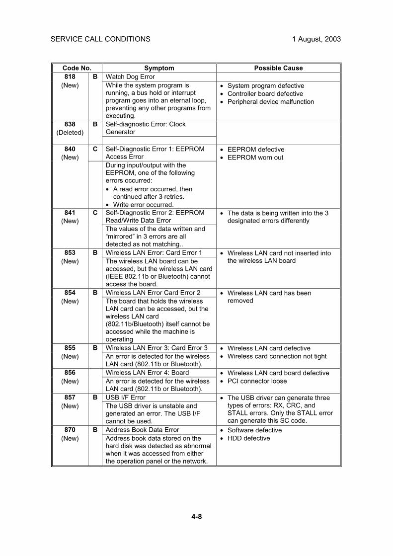
SERVICE CALL CONDITIONS 1 August, 2003
4-8
Code No. Symptom Possible Cause 818 Watch Dog Error
(New) B
While the system program is running, a bus hold or interrupt program goes into an eternal loop, preventing any other programs from executing.
• System program defective • Controller board defective • Peripheral device malfunction
Self-diagnostic Error: Clock Generator
838 (Deleted)
B
C Self-Diagnostic Error 1: EEPROM Access Error
840 (New)
During input/output with the EEPROM, one of the following errors occurred: • A read error occurred, then
continued after 3 retries. • Write error occurred.
• EEPROM defective • EEPROM worn out
Self-Diagnostic Error 2: EEPROM Read/Write Data Error
841 (New)
C
The values of the data written and �mirrored� in 3 errors are all detected as not matching..
• The data is being written into the 3 designated errors differently
853 Wireless LAN Error: Card Error 1 (New)
B The wireless LAN board can be accessed, but the wireless LAN card (IEEE 802.11b or Bluetooth) cannot access the board.
• Wireless LAN card not inserted into the wireless LAN board
854 Wireless LAN Error Card Error 2 (New)
B The board that holds the wireless LAN card can be accessed, but the wireless LAN card (802.11b/Bluetooth) itself cannot be accessed while the machine is operating
• Wireless LAN card has been removed
855 Wireless LAN Error 3: Card Error 3 (New)
B An error is detected for the wireless LAN card (802.11b or Bluetooth).
• Wireless LAN card defective • Wireless card connection not tight
856 Wireless LAN Error 4: Board (New)
An error is detected for the wireless LAN card (802.11b or Bluetooth).
• Wireless LAN card board defective • PCI connector loose
857 USB I/F Error (New)
B The USB driver is unstable and generated an error. The USB I/F cannot be used.
• The USB driver can generate three types of errors: RX, CRC, and STALL errors. Only the STALL error can generate this SC code.
870 Address Book Data Error (New)
B Address book data stored on the hard disk was detected as abnormal when it was accessed from either the operation panel or the network.
• Software defective • HDD defective

1 August, 2003 SERVICE CALL CONDITIONS
4-9
Trou
ble-
shoo
ting
Code No. Symptom Possible Cause 871 FCU Flash ROM Error
(New) B
The address book written into the flash ROM mounted on the FCU is detected as defective.
• Flash ROM device defective • Replace flash ROM on the MBU
880 MLB Error (New)
B A request for access to the MLB (Media Link Board) was not answered within the specified time.
• MLB defective
920 Printer Error 1 (New)
B An internal application error was detected and operation cannot continue.
• Software defective • Insufficient memory
925 Network File Error (New)
B NIA
• NIA
964 Scanner Start Error (Revised)
C During scanned image processing, another command to start scanning was received.
• Software defective
992 Unexpected Software Error (New)
A Software encountered an unexpected operation not defined under any SC code.
• Software defective • An error undetectable by any other
SC code occurred
995 Machine Type Information Error (New)
A After the machine is powered on, a mismatch is detected between the CPM information sent from the controller to the engine and the CPM information specified by the DIP SW settings.
The B135 (35 cpm) and B138 (45 cpm) use the same controller board, but the DIP SW settings must be set correctly for the machine speed. For details, see Section �3. Replace and Adjustment�.
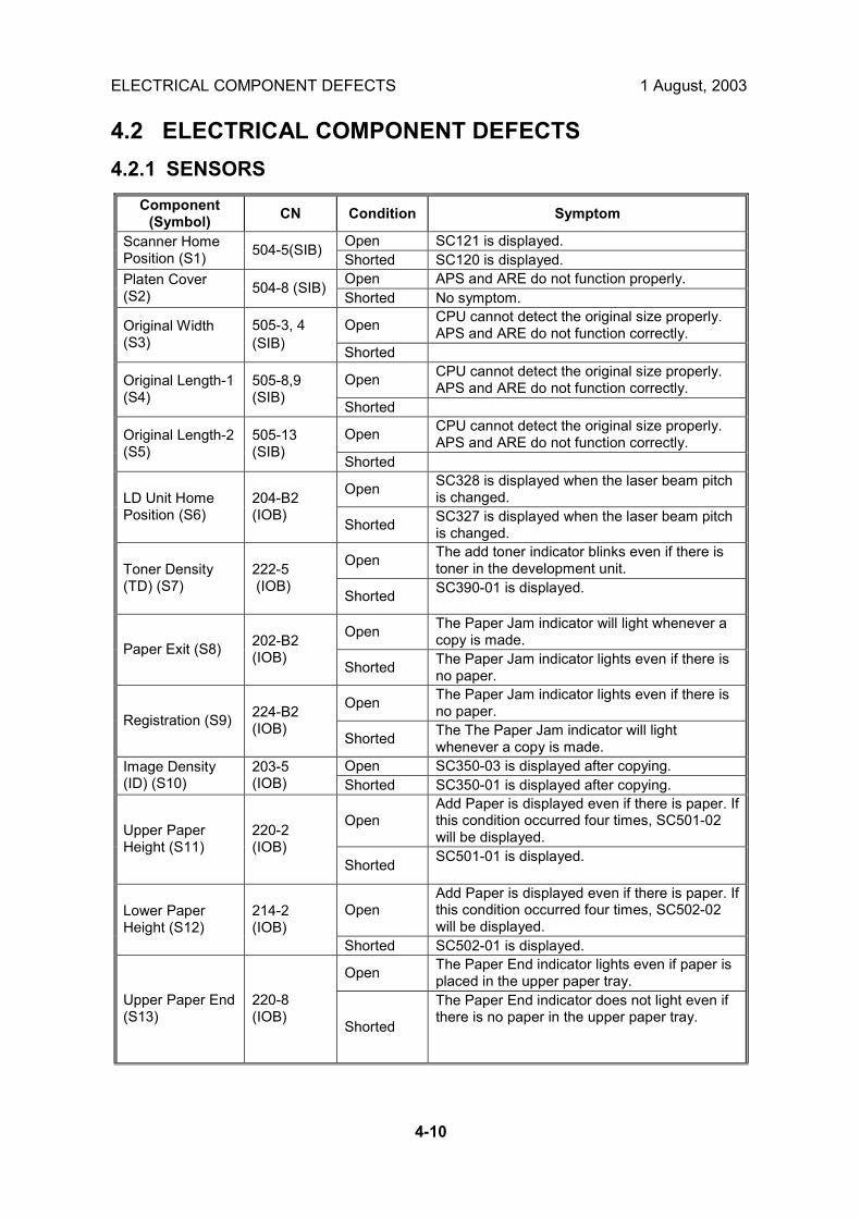
ELECTRICAL COMPONENT DEFECTS 1 August, 2003
4-10
4.2 ELECTRICAL COMPONENT DEFECTS 4.2.1 SENSORS
Component (Symbol) CN Condition Symptom
Open SC121 is displayed. Scanner Home Position (S1) 504-5(SIB)
Shorted SC120 is displayed. Open APS and ARE do not function properly. Platen Cover
(S2) 504-8 (SIB) Shorted No symptom.
Open CPU cannot detect the original size properly. APS and ARE do not function correctly. Original Width
(S3) 505-3, 4 (SIB) Shorted
Open CPU cannot detect the original size properly. APS and ARE do not function correctly. Original Length-1
(S4) 505-8,9 (SIB)
Shorted
Open CPU cannot detect the original size properly. APS and ARE do not function correctly. Original Length-2
(S5) 505-13 (SIB)
Shorted
Open SC328 is displayed when the laser beam pitch is changed. LD Unit Home
Position (S6) 204-B2 (IOB)
Shorted SC327 is displayed when the laser beam pitch is changed.
Open The add toner indicator blinks even if there is toner in the development unit. Toner Density
(TD) (S7) 222-5 (IOB)
Shorted SC390-01 is displayed.
Open The Paper Jam indicator will light whenever a copy is made. Paper Exit (S8) 202-B2
(IOB) Shorted The Paper Jam indicator lights even if there is
no paper.
Open The Paper Jam indicator lights even if there is no paper. Registration (S9) 224-B2
(IOB) Shorted The The Paper Jam indicator will light
whenever a copy is made. Open SC350-03 is displayed after copying. Image Density
(ID) (S10) 203-5 (IOB) Shorted SC350-01 is displayed after copying.
Open Add Paper is displayed even if there is paper. If this condition occurred four times, SC501-02 will be displayed. Upper Paper
Height (S11) 220-2 (IOB)
Shorted SC501-01 is displayed.
Open Add Paper is displayed even if there is paper. If this condition occurred four times, SC502-02 will be displayed.
Lower Paper Height (S12)
214-2 (IOB)
Shorted SC502-01 is displayed.
Open The Paper End indicator lights even if paper is placed in the upper paper tray.
Upper Paper End (S13)
220-8 (IOB)
Shorted
The Paper End indicator does not light even if there is no paper in the upper paper tray.

1 August, 2003 BLOWN FUSE CONDITIONS
4-11
Trou
ble-
shoo
ting
Component (Symbol) CN Condition Symptom
Open The Paper End indicator lights even if paper is placed in the lower paper tray. Lower Paper End
(S14) 214-8 (IOB) Shorted The Paper End indicator does not light even if
there is no paper in the lower paper tray.
Open The Paper Jam indicator will light whenever a copy is made. Upper Relay
(S15) 220-5 (IOB)
Shorted The Paper Jam indicator lights even if there is no paper.
Open The Paper Jam indicator will light whenever a copy is made. Lower Relay
(S16) 214-5 (IOB)
Shorted The Paper Jam indicator lights even if there is no paper.
Open No symptom Transfer Belt Position (S19)
202-A10 (IOB) Shorted SC403 is displayed
4.2.2 SWITCHES
Component (Symbol) CN Condition Symptom
Open �Doors/Covers Open� is displayed even if the right lower cover is closed. Right Lower
Cover (SW1) 216-4 (IOB) Shorted The LCD goes blank when the lower cover is
opened. Open The machine does not turn on.
Main (SW3) 102-1~4 (PSU) 107-1 Shorted The machine does not turn off.
Open �Doors/Covers Open� is displayed even if the front cover is closed. Front Cover
Safety (SW4) 107-1 (PSU) Shorted �Doors/Covers� Open is not displayed even if the
front cover is opened.
4.3 BLOWN FUSE CONDITIONS
Rating Fuse 115V 210 ~ 230V
Symptom at power on
Power Supply Board FU1 6.3A / 125V 6.3A / 250V �Doors/Covers Open� is displayed
FU2 6.3A / 125V 6.3A / 250V �Doors/Covers Open� for the finisher is displayed
FU3 6.3A / 125V 6.3A / 250V Paper end condition FU5 6.3A / 125V 6.3A / 250V SC302, or SC403, or SC405 displayed FU6 3.15A/125V 3.15A/250V FU9 4A/125V 4A/250V
FU101 15A / 125V --- No response FU102 10A / 125V 5A / 250V No response FU103 2A / 125V 1A / 250V Normal operation (optional heaters do not work)

LEDS 1 August, 2003
4-12
4.4 LEDS BICU LED Sequences
LED 101 (Green)
LED 102 (Red)
LED 103 (Orange)
Normal Operation Flashes Off Flashes System Startup Flashes On (1~2s) then Off Flashes Firmware Update: Normal Execution
Flashes On Flashes
Firmware Update: Error Flashes Flashes Flashes Firmware Update: Normal End Flashes Off Flashes Energy Save Mode Off Off Off
Controller LED Sequences
LED 1 (Red)
LED 2 (Red)
System Startup (including Self-Diagnostics) On Off Self-Diagnostic Error On On Normal Operation Flashes Off Firmware Update: Normal Execution Flashes Flashes Firmware Update: Error Off Off Firmware Update: Normal End On On
NOTE: LED 1 monitors Data Bus Bit 14, LED 2 monitors Data Bus Bit 15. 4.5 TEST POINTS Controller Board
Number Monitored Signal TP1 GND TP3 GND TP6 GND TP8 DB0 RXD TP9 DB0 TXD TP10 GND TP11 +5VE TP12 GND TP13 +5V TP14 +5VE TP15 GND TP16 R_FGATE TP17 W_FGATE

1 August, 2003 SERVICE PROGRAM MODE TABLES
5-1
Serv
ice
Tabl
es
5. SERVICE TABLES !CAUTION Never turn off the main power switch when the power LED is lit or flashing. To avoid damaging the hard disk or memory, press the operation power switch to switch the power off, wait for the power LED to go off, and then switch the main power switch off.
NOTE: The main power LED lights or flashes while the platen cover or ARDF is open, while the main machine is communicating with a facsimile or the network server, or while the machine is accessing the hard disk or memory for reading or writing data.
5.1 SERVICE PROGRAM MODE TABLES Please note these general changes in this section: • Group 8 (Data Log 2) is a new group of counters. • Along with the addition of Group 8, many of the Group 7 counters have been
removed. 5.1.1 SERVICE TABLE KEY Notation What it means [range / default / step] Example: [-9 ~ +9 / +3.0 / 0.1 mm step]. The setting can be
adjusted in the range ±9, value reset to +3.0 after an NVRAM reset, and the value can be changed in 0.1 mm steps with each key press.
* Value stored in NVRAM. After a RAM reset, this default value (factory setting) is restored.
1111 An SP number set in bold-italics denotes a �Special Service Program� mode setting that appears only after entering the SP mode by pressing " on the 10-key pad and �Copy SP� on the touch-screen together.
B135 Denotes the 35 cpm model. B138 Denotes the 45 cpm model. DFU Denotes �Design or Factory Use�. Do not change this value. Japan only The feature or item is for Japan only. Do not change this value. LEF Long Edge Feed SEF Short Edge Feed (☛6.2 Image Processing) Refer to �6.2 Image Processing� in �6. Details�.
Due to fundamental changes in how image processing adjustment is done with Group 4 SP codes, more details are provided in Section 6.

SERVICE PROGRAM MODE TABLES 1 August, 2003
5-2
5.1.2 SERVICE TABLES
SP1-xxx: Feed Leading Edge Registration [+9 ~ �9 / 3.0 / 0.1 mm] 1001* Adjusts the printing leading edge registration using the trimming area pattern (SP2-902-3, No.11). Use ! to toggle between ± before entering the value. Specification: 3 ±2 mm
Side-to-Side Registration 1002* Adjusts the printing side-to-side registration from the 3rd paper feed station using the trimming area pattern (SP2-902-3, No.11).Tray3, Tray4 for Paper Feed Unit. Use the ! key to toggle between + and � before entering the value. Specification: 2 ±1.5 mm
1002 1 Tray 1 [�9 ~ +9/ +3.0 mm / 0.1 mm step] 1002 2 Tray 2 [�9 ~ +9/ +3.0 mm / 0.1 mm step] 1002 3 Tray 3 [�9~ +9/ +2.0 mm / 0.1 mm/step] 1002 4 Tray 4 [�9~ +9/ +2.0 mm / 0.1 mm/step] 1002 5 From Duplex Tray [�9 ~ +9/ +0.0 mm / 0.1 mm/step] 1002 6 Bypass Feed [�9 ~ +9/ +3.0 mm / 0.1 mm/step] 1002 7 LCT (if present) [�9 ~ +9/ +1.5 mm / 0.1 mm/step]
Registration Buckle Adjustment 1003* Adjusts the relay clutch timing at registration. Relay clutch timing determines the amount of paper buckle at registration. (A �+� setting causes more buckling.)
1003 1 Trays 2,3,4 LCT 1003 2 Duplex 1003 5 Bypass 1003 4 Tray 1 Feed 1003 5 Bypass Thick Paper
[�9 ~+9 / 0 /1 mm step]
By-pass Feed Paper Size Display 1007* Displays the paper width sensor data for the by-pass feed table.
Exit Junction Solenoid Start Timing 1012* Adjusts the timing of the solenoids at the entrance and exit of the paper exit section to accommodate the increased speed of the duplex unit. This SP has been added to compensate for the increased operation speed of the duplex unit for this machine. Increase the value if the leading edges are jamming. Decrease the value if trailing edges are bending at the entrance
1012 1* Exit Entrance Junction Solenoid
B135: [200 ~ 450 ms / 370 ms / 10 ms] B138: [200 ~ 450 ms / 300 ms /10 ms]
1012 2* Exit Last Junction Solenoid B135: [200 ~ 450 ms / 370 ms / 10 ms] B138: [200 ~ 450 ms / 370 ms /10 ms]]

1 August, 2003 SERVICE PROGRAM MODE TABLES
5-3
Serv
ice
Tabl
es
Fusing Idling 1103* Switches fusing idling on/off. When on, printing will not start until enough time has elapsed so the hot roller can reach optimum temperature. This ensures even heat on the hot roller. Switch on if fusing on the 1st and 2nd copies is incomplete (this may occur if the room is cold.) You must switch SP1103-1 ON before you set the fusing interval with SP1103-2.
1103 1* Enable Fusing Idling 0 = Off, 1 = On 1103 2* Fusing Idling Interval [0 ~ 60 sec. / 30 sec. / 1 sec.]
Fusing Temperature Control [0~1 / 0 / 1] 1104* Selects the fusing temperature control method. After changing this setting, be sure the power the machine off and on again with the main power switch to enable the new setting. 0: Normal (ON/OFF control). Allows full application from ac power supply to bring
the hot roller up to the target fusing temperature then shuts off. Determines the on time from the present temperature (detected by the thermistor on the hot roller) and the temperature of 1 cycle before.
1: Phase (hysterisis) control. Sets the upper and lower limits for the temperature; at the lower temperature the fusing lamp is on and at the higher temperature the fusing lamp is off.
Change this setting to �0� only if the user has excessive electrical noise or interference on the power supply line. Such interference can cause voltage to drop when power is applied using the ON/OFF control method. Interference can be caused by the general poor quality of the power supply lines, or if the machine is sharing a power supply with other electrical devices such as fluorescent lights. Before changing this setting, make sure that the machine is connected to a power supply not shared by other electrical equipment. Note: Selecting Phase control (�1�) could cause the fusing temperature control board to emit low pitched noise.

SERVICE PROGRAM MODE TABLES 1 August, 2003
5-4
Fusing Temperature Adjustment 1105* Allows adjustment of the hot roller temperature at the center and ends of the roller for the quality or thickness of the paper. The hot roller in this machine has two fusing lamps: one heats the center of the roller, the other heats both ends. Each fusing lamp can be adjusted separately. The �re-load temperature� is the �print ready temperature. When the fusing temperature exceeds this setting, the machine can operate. Do not set up a re-load temperature (Re-load Temp. = Fusing. Temp � SP Value.) that is higher than the SP1-105-2 setting. Roller Center: Trays 35 cpm: [120 ~ 200/ 150 / 1 deg.]
45 cpm: [120 ~ 200 / 170 / 1 deg.] 1105 1
Adjusts the fusing temperature at the center of the hot roller. Roller Ends: Trays 35 cpm: [120 ~ 200 / 160 / 1 deg.]
45 cpm: [120 ~ 200 / 175 / 1 deg.] 1105 2
Adjusts the fusing temperature at the ends of the hot roller. Roller Center � Bypass 35 cpm: [120 ~ 200 / 160 / 1 deg.]
45 cpm: [120 ~ 200 / 170 / 1 deg.] 1105 3
Adjusts the fusing temperature at the center of the hot roller for bypass feed. Roller Center - Ends 35 cpm: [120 ~ 200 / 160 / 1 deg.]
45 cpm: : [120 ~ 200 / 170 / 1 deg] 1105 4
Adjusts the fusing temperature at the ends of the hot roller for bypass feed. Re-load Temp. Minus: Roller Center
[0 ~ 60 / 30 / 1 step] 1105 5
Sets the temperature for re-heating the hot roller center. Re-load Temp. Minus: Roller Ends
[0 ~ 60 / 30 / 1 step] 1105 6
Sets the temperature for re-heating the hot roller ends. Roller Center: Bypass (Thick Paper)
35 cpm: [120 ~ 200 / 170 / 1 deg] 45 cpm: [120 ~ 200 / 170 / 1 deg]
1105 7
Adjusts the fusing temperature at the center of the hot roller for thick paper. Roller Ends: Bypass (Thick Paper)
35 cpm: [120 ~ 200 / 170 / 1 deg] 45 cpm: [120 ~ 200 / 170 / 1 deg]
1105 8
Adjusts the fusing temperature at the ends of the hot roller for thick paper. Re-load Temp. Minus: Roller Center (Thick Paper)
35 cpm: [0 ~ 60 / 0oC/ 5] 45 cpm: [0~ 60 / 5oC /1]
1105 9*
Sets the temperature for re-heating the hot roller center for thick paper. Re-load Temp. Minus: Roller Ends (Thick Paper)
35 cpm: [0 ~ 60 / 0oC/ 5] 45 cpm: [0~ 60 / 5oC /1]
1105 10*
Sets the temperature for re-heating the hot roller ends for thick paper.

1 August, 2003 SERVICE PROGRAM MODE TABLES
5-5
Serv
ice
Tabl
es
1106 Fusing Temperature Display
1106 1 Roller Center Displays the fusing temperature for the center of the hot roller.1106 2 Roller Ends Displays the fusing temperature for the ends of the hot roller. 1106 3 I/O Board Temp.
at Power On Displays in the internal temperature of the machine when it was powered on.
Fusing Nip Band Check [0=Off, 1=On] 1109* Checks the fusing nip band.
Paper Reverse Timing (Duplex) [+5 ~ �5 / 0 mm / 1 mm step] 1111* Adjusts the timing for stopping the rotation of the reverse roller after the trailing edge of the paper passes the duplex entrance sensor. Adjust the timing if paper frequently jams at the inverter gate in the duplex unit.
Motor Speed Adjustment 1801* Adjusts the speeds of the main motor, feed/development motor, and fusing exit motor. Each step decreases or increases motor speed in 0.15% increments
1801 1 Main Motor [-4 ~ +4 / 0 / 0.15%] 1801 2 Feed/Development Motor [-4 ~ +4 / 0 / 0.15%] 1801 3 Fusing/Exit Motor [-4 ~ +4 / 0 / 0.15%]

SERVICE PROGRAM MODE TABLES 1 August, 2003
5-6
SP2-xxx: Drum 2001* Charge Roller Bias Adjustment
Copying [�1000 ~ �2000 / �1450V / 10V step] 2001 1* Adjusts the voltage applied to the charge roller for copying. ID Sensor Pattern [0 ~ 700 / 200V / 10V step] 2001 2* Adjusts the voltage applied to the charge roller when making the VSDP ID sensor pattern (for charge roller voltage correction). The actual charge roller voltage is this value plus the value of SP2001 1.
2005* Charge Roller Bias Correction
Charge Roller Voltage Correction 1 [0.1 ~ 1.0 / 0.85 / 0.05 step] 2005 1* Adjusts the lower threshold value for the charge roller correction. When the value of VSP/VSG is greater than this value, the charge roller voltage increases by 30 V (e.g., from �500 to �530). Charge Roller Voltage Correction 2 [0.1 ~ 1.0 / 0.90 / 0.05 step] 2005 2* Adjusts the upper threshold value for the charge roller correction. When the value of VSP/VSG is greater than this value, the charge roller voltage decreases by 30 V (absolute value). Charge Roller Voltage Adjustment 1 [�1000 ~ �2000 / 1450V / 10V step] 2005 3* Adjusts the lower limit value for charge roller voltage correction. Charge Roller Voltage Adjustment 2 [�1000 ~ �2000 / 2000V / 10V step] 2005 4* Adjusts the upper limit value for charge roller voltage correction. Charge Roller Voltage Step [0 ~ 100V / 30V / 10V step] 2005 5* Adjusts the correction voltage adjustment step size.
Printing Erase Margin 2101* Adjusts the leading edge (top), trailing edge (bottom), left, and right margins
2101 1* Leading Edge (Top) [0.9 ~ 9.0 / 3 / 0.1 mm step] Spec: ±2 mm 2101 2* Trailing Edge (Bottom) [0.9 ~ 9.0 / 3 / 0.1 mm step] Spec: ±2 mm 2101 3* Left Edge [0.9 ~ 9.0 / 2 / 0.1 mm step] Spec: ±1.5 mm 2101 4* Right Edge [0.9 ~ 9.0 / 2 / 0.1 mm step] Spec: ±1.5 mm 2101 5* Trailing Edge - Back side [0.0 ~ 4.0 / 1.2 / 0.1 mm step]
Recommended: 2 ±1.5 mm 2101 6* Back Side - Right [0.0 ~ 9.0 / 0.3 / 0.1 mm step]
Recommended: 2 ±1.5 mm 2101 7* Back Side - Left [0.0 ~ 9.0 / 0.3 / 0.1 mm step]
Recommended: 2 +2.5/-1.5 mm
LD Power Adjustment DFU 2103* Adjusts the intensity of the laser for the copier, printer, and fax unit. The Copier and Printer/Fax settings can be adjusted separately.
2103 1* LD1 (Copier) [�55 ~ +64 / �5 /1 LSB step] Approx. 50/128 = .4%
2103 2* LD2 (Copier) [�55 ~ +64 / �20 /1 LSB step] Approx. 50/128 = .4%
2103 3* LD1 (Printer, FAX) [�50 ~ �35 / �25 /1 LSB step] 2103 4* LD2 (Printer, FAX) [�50 ~ �35 / �25 /1 LSB step] 2103 5* LD1 Adjustment Start/End OFF/ON 2103 6* LD2 Adjustment Start/End OFF/ON

1 August, 2003 SERVICE PROGRAM MODE TABLES
5-7
Serv
ice
Tabl
es
LD Beam Pitch Adjustment 2109* Adjusts the beam gap for the dual beam system. After replacing the LD unit or replacing or clearing the NVRAM, use this SP mode to adjust the laser beam pitch. This adjustment is performed by specifying the number of pulses to the stepper motor that will adjust the angle of rotation of the LD unit from the home position. 400 dpi [400 dpi: [8 ~ 262 / 144 / 1 pulse step] 2109 1* Adjusts the laser beam pitch value for 400 dpi resolution. After replacing the LD unit or replacing or clearing NVRAM, use this SP and SP2-109-3 to adjust the laser beam pitch. 600 dpi [600 dpi: [30 ~ 284 / 168 / 1 pulse step] 2109 2* Adjusts the laser beam pitch value for 600 dpi resolution. After replacing the LD unit or replacing or clearing NVRAM, use this SP and SP2-109-4 to adjust the laser beam pitch. 400 dpi Initial Setting 2109 3* Initializes the laser beam pitch for 400 dpi using the value for SP2-109-1. After entering a value for SP2-109-1, this SP must be used. 600 dpi Initial Setting 2109 4* Initializes the laser beam pitch for 600 dpi using the value for SP2-109-2. After entering a value for SP2-109-2, this SP must be used. Auto Pitch Adjustment Interval
[0 ~ 65535 / 1000 / 1 step] 2109 5*
Sets the interval for automatic laser beam pitch adjustment. When the number of times that the resolution has been changed reaches this value, the laser unit position is automatically corrected. Current LD Unit Position 2109 6 Displays the current LD unit position (number of pulses from home position). If this is different from the value of 2-109-1 or 2-109-2, LD unit positioning has failed. Beam Pitch Change Counter 2109 7 Displays how many times the LD unit position has been changed (how many times the resolution has changed.) When the laser beam pitch adjustment is done, this counter is reset to zero. Beam Pitch Data Reset 2109 8 Resets the values of SP2-109-6 and SP2-109-7. After replacing the LD unit, this SP mode must be performed. See the LD Unit Removal Procedure.
Test Mode dpi DFU, [See below / 8 / 0 ~ 18] 2110 Sets the scanning resolution (dpi). (Range values: 0 = 400 x 400 dpi, 1 = 391 x 406 dpi, 4= 300 x 300 dpi, 8 = 600 x 600 dpi, 15 = 439 x 430 dpi, 16 = 476 x 476 dpi, 17 = 483 x 465 dpi, 18 = 465 x 483 dpi)
Polygon Motor Off Timer [0 ~ 60 s / 10 s / 5 s step] 2112 Input the time that the polygon motor is to switch off after the printer has remained idle for the specified time and entered the standby mode. If set to zero, the polygon motor never switches off in standby mode. However, if the machine enters the energy saver mode, the polygon motor will ignore the zero setting and switch itself off.

SERVICE PROGRAM MODE TABLES 1 August, 2003
5-8
2201* Development Bias Adjustment
Development Bias [-200 ~ -700 / -510V / 10V step] 2201 1* Adjusts the development bias for copying. Use as a temporary measure to correct faint copies from an aging drum. ID Sensor Pattern [- 200 ~ -700 / -380V / 10V step] 2201 2* Adjusts the development bias for the ID sensor pattern for VSP
Forced Toner Supply 2207 Forces the toner bottle to supply toner at 1-second intervals for up to 30 seconds. To start, press ".
Toner Supply Mode [0: Sensor control, 1: Image pixel count] 2208* Selects the toner mode. If you select 1, SP2-209-002 should be set to its default value. Use image pixel count modes only as a temporary measure if the ID or TD sensor is defective.
2209* Toner Supply Rate
Toner Rate [10 ~ 800 mg/s / 60 mg/s / 5 mg/s step] Sets the amount of toner supplied every second by the toner supply motor. Increasing this value reduces the toner supply clutch on time. Use a lower value if the user tends to make lots of copies that have a high proportion of black. Toner Supply Correction Data [25 ~ 300 / 300 / 25 step] 2209 2* Displays the toner supply correction coefficient (K). It can also be used to adjust K, but the value is changed again when VT is measured for the next copy. The toner supply rate depends on the amount of toner in the toner bottle. This change is corrected using this coefficient. This SP can be used to check the toner supply condition. The lower the value of K, the lower the toner density
ID Sensor Pattern Interval 2210* Sets the interval between ID sensor pattern prints. Job Page Count [0 ~ 200 / 10 / 1] 2210 1* Sets the interval between ID sensor pattern printing. For users that do not make many copies daily, set a smaller interval to compensate for the effects of seasonal and weather changes. Forced Page Count [2 ~ 999 / 200 / 1] 2210 2* Forces creation of the ID sensor pattern to prevent low density copies for customers who use the copier for long copy jobs.
Copies After Toner Near-End [0: 90 copies, 1: No copies, 2: 10 copies] 2213* Selects the number of copies that can be printed once the copier has detected toner near-end. Select 1 or 2 if the customer normally makes copies of high density
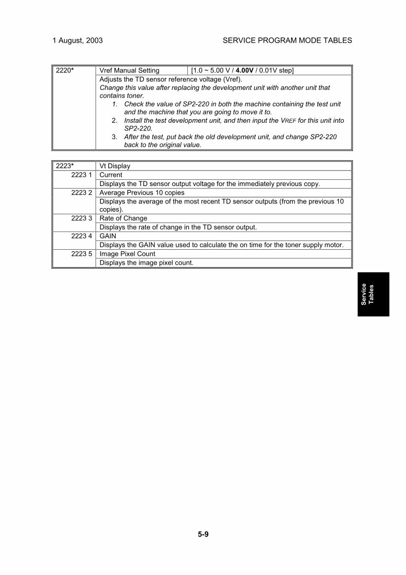
1 August, 2003 SERVICE PROGRAM MODE TABLES
5-9
Serv
ice
Tabl
es
Vref Manual Setting [1.0 ~ 5.00 V / 4.00V / 0.01V step] 2220* Adjusts the TD sensor reference voltage (Vref). Change this value after replacing the development unit with another unit that contains toner.
1. Check the value of SP2-220 in both the machine containing the test unit and the machine that you are going to move it to.
2. Install the test development unit, and then input the VREF for this unit into SP2-220.
3. After the test, put back the old development unit, and change SP2-220 back to the original value.
2223* Vt Display
Current 2223 1 Displays the TD sensor output voltage for the immediately previous copy. Average Previous 10 copies 2223 2 Displays the average of the most recent TD sensor outputs (from the previous 10 copies). Rate of Change 2223 3 Displays the rate of change in the TD sensor output. GAIN 2223 4 Displays the GAIN value used to calculate the on time for the toner supply motor. Image Pixel Count 2223 5 Displays the image pixel count.

SERVICE PROGRAM MODE TABLES 1 August, 2003
5-10
2301 Transfer Current Adjustment
1st Side of Paper B135: [20 ~ 100µA / 35 / 1µA step] B138: [20 ~ 100µA / 45] / 1µA step]
2301 1
Adjusts the transfer current for printing the first side of the paper (image area). If the user uses thicker paper, the current may have to be increased to ensure sufficient transfer of toner. 2nd Side of Paper B135: [20 ~ 100µA / 35 / 1µA step]
B138: [20 ~ 100µA / 40] / 1µA step] 2301 2
Adjusts the transfer current for printing the second side of the paper (image area). Leading Edge B135: [20 ~ 100µA / 35 / 1µA step]
B138: [20 ~ 100µA / 45] / 1µA step] 2301 3
Adjusts the transfer current for copying at leading edge of the paper. Increase the current to separate the paper from the drum properly in high humidity and high temperature conditions. Bypass Feed (45ppm) B138: [20 ~ 100µA / 45 / 1µA step] 2301 4 Adjusts the transfer current for copying from the by-pass tray (image area) for the B138 (45 cpm). If the user normally feeds thicker paper from the bypass tray, use a higher setting. Leading Edge Bypass Feed (45ppm)
B138: [20 ~ 100µA / 60 / 1µA step] 2301 5
Adjusts the transfer current for copying at the leading edge of paper fed from the by-pass tray for the B138 (45 cpm). Increase the current to separate the paper from the drum properly in high humidity and high temperature conditions. Bypass Feed (35 ppm) B135: [20 ~ 100µA / 35 / 1µA step] 2301 6 Adjusts the transfer current for copying from the by-pass tray (image area) for the B135 (35 cpm). Leading Edge Bypass Feed (35 ppm) B135: [20 ~ 100µA / 45 / 1µA step] 2301 7 Adjusts the transfer current for copying at the leading edge of paper fed from the by-pass tray for the B135 (35 cpm).

1 August, 2003 SERVICE PROGRAM MODE TABLES
5-11
Serv
ice
Tabl
es
2309* Transfer Current Correction
Paper Lower Width (a) [0 ~ 297 / 150 / 1 mm step] 2309 1 Adjusts the lower paper width threshold for the transfer current, charge voltage, and development bias corrections. Use this SP when an image problem (e.g., insufficient toner transfer) occurs with a small width paper. If the paper width is smaller than this value, the transfer current will be multiplied by the factor in SP2-309-3 (paper tray) or SP2-309-5 (by-pass). Paper Upper Width (b) [0 ~ 297 / 216 / 1 mm step] 2309 2 Adjusts the upper paper width threshold for the transfer current, charge voltage, and development bias corrections. As for SP2-309-1, but the factors are in SP2-309-4 (paper tray) and SP2-309-6 (by-pass). Paper Tray (alpha) [1.0 ~ 3 / 1.2 / 0.1 mm step] 2309 3 Adjusts the transfer current correction coefficient used if the paper width is less than the setting of SP2-309-1. Paper Tray (beta) [1.0 ~ 3 / 1.2 / 0.1 mm step] 2309 4 Adjusts the transfer current correction coefficient used if the paper width is less than the setting of SP2-309-2. By-Pass Feed (gamma) [1.0 ~ 3 / 1.5 / 0.1 mm step] 2309 5 Adjusts the transfer current correction coefficient used if the paper width is less than the setting of SP2-309-1. By-Pass Feed (delta) [1.0 ~ 3 / 1.5 / 0.1 mm step] 2309 6 Adjusts the transfer current correction coefficient used if the paper width is less than the setting of SP2-309-2.
TD Sensor Initial Setting 2801* Performs the TD sensor initial setting. This SP mode controls the voltage applied to the TD sensor to make the TD sensor output about 4.0 V. Press �Execute� to start. After finishing this, the TD sensor output voltage is displayed. Use this mode only after installing the machine, changing the TD sensor, or adding new developer.
TD Sensor Manual Setting 2802* Allows you to adjust the TD sensor output manually for the following. VTS [1.00 ~ 5.00V / 4.78V / 0.02V step] 2802 1 Adjusts the TD sensor output (VT). Change this value after replacing the development unit with another one that already contains toner. For example, when using a development unit from another machine for test purposes. To adjust VT, use a similar procedure as for SP2-220. VTMAX [1.00 ~ 5.00V / 4.78V / 0.02V step] 2802 2 Adjusts the maximum value for SP2802 1. VTMIN [1.00 ~ 5.00V / 1.00V / 0.02V step] 2802 3 Adjusts the minimum value for SP2802 1.
Developer Initialization 2805* Performs the TD sensor initial setting. This SP mode controls the voltage applied to the TD sensor to make the TD sensor output about 4.0 V. Press �Execute� to start. After finishing this, the TD sensor output voltage is displayed. Use this mode only after installing the machine, changing the TD sensor, or adding new developer.

SERVICE PROGRAM MODE TABLES 1 August, 2003
5-12
2902 Test Pattern
IPU Test Pattern Pattern 0 ~ 15 2902 2 Prints the test patterns for the IPU chip. This SP mode is useful for finding whether the BICU or the SBU is defective. If the printout is not OK, the BICU is defective. Printing Test Pattern Pattern 0 ~ 38 2902 3 Prints the printer test patterns. Select the number of the test pattern that you want to print. This SP mode is useful for finding whether the LDDR or the BICU is defective. If the printout is not satisfactory, the LDDR is defective.
Main Scan Magnification 2909* Adjusts the magnification in the main scan direction for copy mode and printer mode. Press ! to toggle ±.
2909 1* Copier [�2.0 ~ +2.0 / 0 / 0.1% step] 2909 2* Printer [�2.0 ~ +2.0 / 0 / 0.1% step]
2911 Transfer Current On/Off Timing
La (On Timing) [�30 ~ +30 / 0 mm / 1 mm step] 2911 1 Adjusts the transfer current on timing at leading edge. Lb (Switch Timing) [0 ~ +30 / 10 mm / 1 mm step] 2911 2 Adjusts the transfer current switch timing. This determines when the leading edge stops and the image area current begins (see SP2-301). Lc (Off Timing) [�30 ~ +30 / � 5 mm / 1 mm step] 2911 3 Adjusts the transfer current off timing. (e.g. �5 mm is 5 mm after the trailing edge.)
2912* Drum Reverse Rotation Interval DFU
Print Density for Test Pattern [0 ~ 15 / 15 / 1] 2913* Sets the print density for the patterns printed with SP2-902-3.

1 August, 2003 SERVICE PROGRAM MODE TABLES
5-13
Serv
ice
Tabl
es
2914* Process Control Setting
C-alpha [0 ~ 400 / 150 / 10V step] 2914 1* Adjusts the charge roller voltage used when paper with a small width is fed from the by-pass tray. The paper width below which the correction starts depends on the value of SP2-309-1. Use this SP when an image problem (such as white spots at the center of black dots or breaks in thin black lines) occurs when paper with a small width is fed from the by-pass feed tray. C-beta [0 ~ 400 / 0 / 10V step] 2914 2* Adjusts the charge roller voltage used when paper with a small width is fed from the by-pass tray. The paper width below which the correction starts depends on the value of SP2-309-2. Use this SP when an image problem (see 2-914-1) occurs when paper with a small width is fed from the by-pass feed tray. B-gamma [0 ~ 300 / 200 / 10V step] 2914 3* Adjusts the development bias used when paper with a small width is fed from the by-pass tray. The paper width below which the correction starts depends on the value of SP2-309-1. Use this SP when an image problem (see 2-914-1) occurs when paper with a small width is fed from the by-pass feed tray. B-delta [0 ~ 300 / 50 / 10V step] 2914 4* Adjusts the development bias used when paper with a small width is fed from the by-pass tray. The paper width below which the correction starts depends on the value of SP2-309-2. Use this SP when an image problem (see 2-914-1) occurs when paper with a small width is fed from the by-pass feed tray.
2920 LD Off Check DFU
Toner Overflow Sensor [0 = No, 1 = Yes] 2960* Selects whether or not the toner overflow sensor is activated.
Transfer Cleaning Blade Forming
[0 ~ 30/ 0 / 1 sheets] 2964*
Applies a pattern of toner to the transfer belt at a defined interval between sheets on the transfer belt in order to reduce friction between the belt surface and the cleaning blade. Under conditions of high temperature and high humidity, the density control feature may reduce the amount of toner, which also reduces the amount of toner on the surface of the transfer belt. With less toner on the belt, the friction between the belt and the blade increases, and could cause the blade to bend or scour the surface of the belt.

SERVICE PROGRAM MODE TABLES 1 August, 2003
5-14
2969* LD � PWM Selection
Printer Output LD � PWM Selection [1 ~ 4 / 1 / 1 step] 2969 1* Changes the LD power PWM control for printed copies. A smaller value produces a lighter image. Use this SP to adjust the image density for printing from a personal computer or printing a received fax message. 1: 87.5% 2: 75% 3: 62.5% 4: 50% Fax Output LD � PWM Selection [1 ~ 4 / 1 / 1 step] 2969 2* Changes the LD power PWM control for printed fax messages. A smaller value produces a lighter image. Use this SP to adjust the image density for printing fax messages. 1: 87.5% 2: 75% 3: 62.5% 4: 50%
2971 Toner Full Sensor Count DFU
Grayscale Limit 2972* A new feature of this machine that controls the halftone density level to prevent deterioration of the OPC. The halftone density is detected by the ID sensor, and the machine adjusts the intensity of the LD beam according to the upper/lower limit setting. Upper Limit [0 ~ 100 / 60 / 1 step] 2972 1* Defines the upper limit for grayscale. A larger value allows a wider range of halftones at the pale end of the scale. If the image contains pale areas with fuzzy borders surrounded by dark areas, reduce this value to make the borders clearer. Lower Limit [0 ~ 100 / 40 / 1 step] 2972 2* Defines the lower limit for grayscale. A smaller value allows a wider range of halftones at the dark end of the scale.
Grayscale Copy Interval Check [0 ~ 1000 / 100 / 10 step] 2973* Sets the halftone operation interval in order to prevent deterioration of the OPC. If the number of copies exceeds this setting, at the end of the job, or if the door is opened and closed, charge correction is executed.
Image Density Adjustment [1 ~ 5 / 3 / 1 step] 2974* Adjusts image density. Changing this setting adjusts development bias and ID sensor output voltage that in turn raises or lowers image density.
Toner End Detection ON Time
[0 ~ 2,000 / 0 / 10 s step] 2975*
Sets a time limit for issuing the toner near end warning on the operation panel. The time may need to be shorter for customers who run especially large print jobs (working at night, for example) to ensure earlier warning of the toner near end condition so toner out does not interrupt a long job. 0: Normal end detection (90 sheets after near-end detected (SP2213)

1 August, 2003 SERVICE PROGRAM MODE TABLES
5-15
Serv
ice
Tabl
es
Toner Bottle Total On Time [0 ~ 2,000,000 / 0 / 1 ms step] 2976* Displays the total ON time of the toner supply motor, calculated from when the toner bottle was replaced. Use this to check that the toner end count (SP2975) is working properly. When SP2975 is set to any value other than �0�, this value is displayed when it matches the setting of SP2975. When SP2975 is set to �0�, SP2976 is disabled. SP2976 is automatically set to zero by toner end recovery.)
Charge Counter [0 ~ 1000000 / 0 / 1 step] 2980* Sets the number of pages to print after toner and carrier initialization before the charge input is increased to compensate for deterioration over time in the polarity of the carrier. The strength in the polarity of the carrier in the toner will eventually decrease and cause lower charge output. Setting the charge output to increase after a specified number of copies can compensate for this effect.
Polygon Mirror Rotation Switching
DFU 0: Rpm determined by engine 1: Rpm for B135 (35 cpm) 2: Rpm for B138 (45 cpm)
2981
Switches the number revolutions per minute of the polygon mirror motor.

SERVICE PROGRAM MODE TABLES 1 August, 2003
5-16
SP3-xxx: Process 3001* ID Sensor Initial Setting
ID Sensor PWM Setting [0 ~ 255 / 100 / 1 step] 3001 1 Allows you to reset the PWM of the ID sensor LED to avoid a service call error after clearing NVRAM or replacing the NVRAM. The PWM data is stored by executing SP-3001-2. ID Sensor Initialization � 3001 2 Performs the ID sensor initial setting. ID sensor output for the bare drum (VSG) is adjusted automatically to 4.0 ±0.2 V. Press �Execute� to start. Perform this setting after replacing or cleaning the ID sensor, replacing the drum, or clearing NVRAM.
ID Sensor Output Display 3103* Displays the current VSG, VSP, VSDP, and grayscale control If the ID sensor does not detect the ID pattern, �VSP = 5.0 V/VSG = 5.0 V� is displayed and an SC code is generated. If the ID sensor does not detect the bare area of the drum, �VSP = 0.0 V/VSG =0.0 V� is displayed and an SC code is generated.
3103 1* Vsg (Drum Surface Output) [0V ~ 5.00V] 3103 2* Vsp (Pattern Output) [0V ~ 5.00V] 3103 3* Vsdp (Immediate Post-
Pattern Output). [0V ~ 5.00V]
3103 4* Vsm/Vsg (Grayscale Post-Pattern Output)
[0V ~ 5.00V]
Hot Roller Stripper Cleaning After Job 3905* Toner and carbon clinging to the hot roller strippers can cause poor print quality. To prevent this, toner and carbon are dislodged from the hot roller strippers in two ways: 1) jogging the fusing/feed-out motor 3 times after every print job. 2) freely rotating the hot roller for 12 s. For details, see Section �6.6.2 Hot Roller Stripper Cleaning�. Also see SP 5959. Number of Rotations [0 ~ 60 / 1 / 1 ] 3905 1* Sets the number of times the fusing/exit motor is switched off/on in order to dislodge toner clinging to the hot roller strippers. Raising this setting can increase wear on the hot roller and cleaning roller and shorten the service life of the hot roller. Number of Pages [0 ~ 1000 / 15 / 1] 3905 2* Sets the number of pages to print before the fusing/feed-out motor is jogged (switched off and on rapidly) to dislodge toner and carbon from the hot roller strippers. Normally the motor is jogged once (switched off and on rapidly) after every print job that exceeds 15 pages.

1 August, 2003 SERVICE PROGRAM MODE TABLES
5-17
Serv
ice
Tabl
es
SP4-xxx: Scanner Scanner Sub Scan Magnification
[�0.9 ~ 0.9 / 0.0 / 0.1% step] 4008*
Adjusts the magnification of the sub scan direction during scanning. Changing this value changes the scanner motor speed. Press ! to toggle ±.
Scanner Leading Edge Registration
[�0.9 ~ 0.9 / 0.0 / 0.1 mm step] 4010*
Adjusts the leading edge registration for scanning. Press ! to toggle ±. As you enter a negative value, the image moves toward the leading edge.
Scanner Side-to-Side Registration
[�4.6 ~ +4.6 / 0.0 / 0.1 mm step] 4011*
Adjusts side-to-side registration for scanning. Press ! to toggle ±. As you enter negative values, the image will disappear at the left, and as you enter positive values, the image will appear at the left.
Scanner Erase Margin 4012* Adjusts scanning margins for the leading and trailing edges (sub scan) and right and left edge (main scan). Do not adjust unless the customer desires a scanner margin greater than the printer margin.
4012 1* Leading Edge [0 ~ 9 / 1.0 / 0.1 mm step] (Specification: 3 ± 2 mm) 4012 2* Trailing Edge [0 ~ 9 / 0.5 / 0.1 mm step] (Specification: 2 ± 2 mm) 4012 3* Right [0 ~ 9 / 0.5 / 0.1 mm step] (Specification: +2.5 ~ -1.5 mm) 4012 4* Left [0 ~ 9 / 1.0 / 0.1 mm step] (Specification: 2 ± 1.5 mm)
Scanner Free Run 4013 Performs a scanner free run with the exposure lamp off.
4016 White Board Read Adjust
4016 1 Read Start Position Adjusts the scanning start position on the white plate for auto shading. The default
is 10.5 mm from the leading edge. The setting specifies how far scanning starts from the default position. [�5.0 ~ +5.0 / 0.0 / 0.1 mm/step]
4016 2 Read Width Adjusts the width of the area on the white plate (in the sub scan direction) that is
scanned for auto shading. The default is 4.76 mm. The current setting specifies the difference from this default. [�5.0 ~ +5.0 / 0.0 / 0.1 mm/step]
4018 Scanner Optical Adjust Axis DFU
4019 Scanner Read Position DFU

SERVICE PROGRAM MODE TABLES 1 August, 2003
5-18
APS Sensor Output Display 4301 Displays the time required to detect the size of the paper on the scanner exposure glass. Asterisks (*) are displayed if the size cannot be detected. Dimensions are displayed in inches for North America and in mm for other areas.
APS A5/LT Size Detection [0: not detected, 1: A5 length 5½ x 8½] 4303* Determines whether the original is A5/HLT size when the APS sensor does not detect the original size. If 1 is selected, paper sizes that cannot be detected are regarded as A5 SEF. If 0 is selected, �Cannot detect original size� will be displayed.
8K/16K Detection 0: 8k/16k not detected,
1: 8K, 16K paper size detect enabled 4305*
Selects whether or not the copier determines that the original is 8K/16K size when the APS sensor does not detect the original size. This SP is intended for use with 8K/16K Chinese paper sizes only and is effective only in China and Taiwan areas.
APS Sensor Output Display 0: Original size detection at power on disabled.
1: Original size detection at power on enabled 4307*
Determines whether or not the original size is detected while the exposure lamp lights during initialization.
4428 Scanner Adjustment DFU
4428 1 Flag Display DFU 4428 2 Start DFU 4428 3 Flag Reset DFU
4901* SBU Setting DFU

1 August, 2003 SERVICE PROGRAM MODE TABLES
5-19
Serv
ice
Tabl
es
Filter Setting 4903* Many filter setting SP modes have discussions in section 6. (☛6.2) Full Size Mode 0: No. Normal operation
1: Yes. Main scan magnification always full-size 4903 5
Selects whether the copy is always full size, even if the magnification ratio has been changed. Set to 1 to check the main scan magnification. If the magnification is not 100%, the image processing circuits could be malfunctioning. This SP is used to determine whether magnification is operating correctly. If this SP is set to 1 can make it easier to determine which part of the IPU is malfunctioning. Image Shift in Magnification DFU, [0~7199 / 0 / 1 step] 4903 7 Adjusts the amount of pixel shift in the main scan direction in the magnification mode. Fax 25%, 50% Reduction DFU, [0~3 / 0 / 1 step] 4903 8* Determines whether 25% and 50% reduction is available in the fax mode. 0: Off 1: Conducts fax mode OR processing for main scan for resolution below 100 dpi
in only Text mode. 2: Conducts pre-filter processing for fax mode. 3: Conducts fax Text mode OR processing for main scan for resolution below 100
dpi. Pre-filter processing is done in every mode except Fax Text mode. 4903 10 to 4903 16, Pre-Filter Processing (☛6.2)
The following 5 SP modes Selects the filter processing setting for smoothing in order to reduce the incidence of moiré in images in different original modes. Specifically, they set 1) the compression rate for parallel lines in the main scan direction and for long lines in the sub scan direction, and 2) the strength of smoothing. Enter the appropriate number with the10-key pad then press ". These settings attempt to smooth lines without making them standout. Increasing the strength of a setting can reduce the incidence of moiré but can also decrease sharpness.
4903 10* Pre-Filter: Text [0~9 / 0 / 1] 4903 12* Pre-Filter: Photo Mode [0~9 / 0 / 1 step] 4903 13* Pre-Filter: Text/Photo [0~9 / 0 / 1 step] 4903 15* Pre-Filter: Light [0~9 / 0 / 1 step] 4903 16* Pre-Filter: Generation [0~9 / 0 / 1 step]
4903 20 to 4903 35, Text Mode MTF Filter Coefficient and MTF Filter StrengthThe following 15 SP modes select either the MTF filter coefficient (Level) or the MTF filter strength for text mode at various reproduction ratios. Each SP applies to either the main-scan direction or the sub-scan direction. (☛6.2)
4903 20* Main Filter Level: Text 25%-64% [0~15 / 9 / 1 step] 4903 21* Sub Filter Level: Text 25%-64% [0~13 / 13 / 1 step] 4903 22* Main Filter Strength: Text 25%-64% [0~7 / 2 / 1 step] 4903 23* Sub Filter Strength: Text 25%-64% [0~15 / 2 / 1 step] 4903 24* Main Filter Level: Text 65%-154% [0~7 / 12 / 1 step] 4903 25* Main Filter Strength: Text 65%-154% [0~13 / 13 / 1 step] 4903 26* Sub Filter Level: Text 65%-154% [0~7 / 2 / 1 step] 4903 27* Sub Filter Strength: Text 65%-154% [0~7 / 2 / 1 step] 4903 28* Main Filter Level: Text 155%-256% [0~15 / 14 / 1 step] 4903 29* Sub Filter Level: Text 155%-256% [0~13 / 13 / 1 step] 4903 30* Main Filter Strength: Text 155%-256% [0~7 / 2 / 1 step] 4903 31* Sub Filter Strength: Text 155%-256% [0~7 / 2 / 1 step] 4903 32* Main Filter Level: Text 257%-400% [0~15 / 15 / 1 step]

SERVICE PROGRAM MODE TABLES 1 August, 2003
5-20
4903 33* Sub Filter Level: Text 257%-400% [0~13 / 13 / 1 step] 4903 34* Main Filter Strength: Text 257%-400% [0~7 / 2 / 1 step] 4903 35* Sub Filter Strength: Text 257%-400% [0~7 / 2 / 1 step]
4903 36 to 4903 38, Photo Mode MTF Filter Coefficients (☛6.2) 4903 36: Selects the MTF filter coefficient for edges in the photo mode 4903 37: Selects the filter coefficient for smoothing in the photo mode. The higher the number you select, the greater the applied smoothing effect. 4903 38: Selects the MTF filter coefficient sharpening an entire image in the Photo mode. For 4093 36 and 4093 38, the higher the number you select, the greater the effect on sharpening low contrast text and thin lines. However, a high setting could cause background to drop or, or cause moiré to appear in photos shaded with dots. (0:Off, 1: Softest, 7: Sharpest)
4903 36* Photo MTF (Edge) [[0~7 / 0 / 1] 4903 37* Smoothing Filter in Photo Mode [0~7 / 2 / 1] 4903 38* Photo MTF (All) [[0~7 / 0 / 1]
4903 39 to 4903 52, Text/Photo Mode MTF Filter Coefficient (☛6.2) The following 8 SP modes select the filter coefficients for either the edges (Edge) or for the entire image (All) for the Text/Photo mode at various reproduction ratios. Generally, increasing the value can improve the appearance of low contrast text; however, it can also cause background to fade or drop out completely or increase the incidence of moiré. Each SP has a range of 0~7 (0:Off, 1: Softest, 7: Sharpest)
4903 39* Text/Photo (Edge) Coefficient 25-64% [0~7 / 1 / 1] 4903 40* Text/Photo (All) Coefficient 25-64% [0~7 / 4 / 1] 4903 43* Text/Photo (Edge) Coefficient 65-154% [0~7 / 1 / 1] 4903 44* Text/Photo (All) Coefficient 65-154% [0~7 / 4 / 1] 4903 47* Text/Photo (Edge) Coefficient 155-256% [0~7 / 1 / 1] 4903 48* Text/Photo (All) Coefficient 155-256% [0~7 / 4 / 1] 4903 51* Text/Photo (Edge) Coefficient 257-400% [0~7 / 1 / 1] 4903 52* Text/Photo (All) Coefficient 257-400% [0~7 / 4 / 1]
4903 55 and 4903 56, MTF Filter Coefficients for Light Originals (☛6.2) These modes select the MTF filter coefficient (Level) and strength for originals scanned in the Pale mode. While these SPs can improve the appearance of low contrast originals, a high setting can also increase the incidence of moiré.
4903 55* Filter Level: Light Original [0~6 / 6 /1] 4903 56* Filter Strength: Light Original 0: 1/32x, 1: 1/16x, 2: 1/8x, 3: 1/4x, 4: 1/2x, 5: 1x,
6: 2x, 7: 4x 4903 57 and 4903 58, MTF Filter Coefficients for Generation Copy (☛6.2)
These modes select the MTF filter coefficient (Level) and strength for originals scanned in the Generation Copy mode. While selecting a higher number strengthens the effect of the filter to improve contrast, a very high setting can increase the incidence of moiré.
4903 57* Filter Level: Generation Copy [0~6 / 3 /1 step] 4903 58* Filter Strength: Generation
Copy 0: 1/32x, 1: 1/16x, 2: 1/8x, 3: 1/4x, 4: 1/2x, 5: 1x, 6: 2x, 7: 4x
4903 60 to 4903 64, Independent Dot Erase Level The following 4 SP modes select the independent dot erase level for originals scanned in different modes. While selecting a higher setting erases more dots, setting a very high setting can cause very fine text or other detail to fade or drop out completely. 1: Weakest (fewest dots erased), 15: Strongest (most dots erased)
4903 60* Independent Dot Erase: Text Mode [0~15 / 5 / 1 step] 4903 62* Independent Dot Erase: Text/Photo [0~15 / 0 / 1 step] 4903 63* Independent Dot Erase: Light Original [0~15 / 0 / 1 step]

1 August, 2003 SERVICE PROGRAM MODE TABLES
5-21
Serv
ice
Tabl
es
4903 64* Independent Dot Erase: Generation Copy [0~15 / 8 / 1 step] 4903 65 to 4903 69, Background Erase Level
The following 5 SP modes adjust the threshold for background erase in originals scanned in different modes. A higher setting reduces more dirty background, but a very high setting can cause the image to reverse or cause other unexpected results. For all these modes, 0 = off (default).
4903 65* Background Erase Level: Text Mode [0~255 / 0 / 1 step] 4903 66* Background Erase Level: Photo Mode [0~255 / 0 / 1 step] 4903 67* Background Erase Level: Text/Photo Mode [0~255 / 0 / 1 step] 4903 68* Background Erase Level: Light Original [0~255 / 0 / 1 step] 4903 69* Background Erase Level: Generation Copy [0~255 / 0 / 1 step]
4903 75 to 4903 77, Line Width Correction 4903 75: Determines whether line thickness is adjusted in the main and/or sub scan direction. Enter the appropriate number with the 10-key pad then press " 4903 76 and 4903 77: Select the threshold for line width detection in originals copied in the Generation Copy mode. Higher numbers make it easier to thicken thin lines.
4903 75* Line Width Correction: Generation Mode 0: None, 1: Thin, 2: Thin, 3: Thick
4903 76* LWC Threshold (Main Scan): Generation Mode [0~5 / 1 / 1 step] 4903 77* LWC Threshold (Sub Scan): Generation Mode [0~5 / 1 / 1 step]
4903 79 to 4903 93, Filter Strength: Edge, Filter Adj.: Edge Detection, Filter Adj.: Magnification (☛6.2) The following 15 SP modes modify the effects of the MTF filter coefficients set by SP 4903 39 to 4903 52. The related SP mode is in parenthesis in the right column. See page 6-28 for details about how they work.
4903 79* Filter Strength: Text/Photo (Edge) 25-64% [0~3 / 3 / 1] (SP4903 039) 4903 80* Filter Adj.: Text/Photo (Edge Det.) 25-64% [0~15 / 3 / 1] ] (SP4903 039) 4903 81* Filter Adj.: Text/Photo (Mag.%) 25-64% [0~15 / 12 / 1] (SP4903 039) 4903 82* Filter Strength: Text/Photo (Edge) 65-154% [0~3 / 3 / 1] (SP4903 043) 4903 83* Filter Adj.: Text/Photo (Edge Det.) 65-154% [0~15 / 3 / 1] (SP4903 043) 4903 84* Filter Adj.: Text/Photo (Mag.%) 65-154% [0~15 / 12 / 1] (SP4903 043) 4903 85* Filter Strength: Text/Photo (Edge) 155-256% [0~3 / 3 / 1] (SP4903 047) 4903 86* Filter Adj.: Text/Photo (Edge Det.) 155-256% [0~15 / 3 / 1] (SP4903 047) 4903 87* Filter Adj.: Text/Photo (Mag.%) 155-256% [0~15 / 12 / 1] (SP4903 047) 4903 88* Filter Strength: Text/Photo (Edge) 257-400% [0~3 / 3 / 1] (SP4903 051) 4903 89* Filter Adj.: Text/Photo (Edge Det.) 257-400% [0~15 / 3 / 1] (SP4903 051) 4903 90* Filter Adj.: Text/Photo (Mag.%) 257-400% [0~15 / 12 / 1] (SP4903 051) 4903 91* Filter Strength: Photo (Edge) [0~3 / 2 / 1] (SP4903 036) 4903 92* Filter Adj.: Photo (Edge Det.) [0~15 / 0 / 1] (SP4903 036) 4903 93* Filter Adj.: Photo (Mag.%) [0~15 / 15 / 1] (SP4903 036)

SERVICE PROGRAM MODE TABLES 1 August, 2003
5-22
IPU Setting 4904* Many IPU setting SP modes have discussions in section 6. (☛6.2) Grayscale Photo Mode 0: Dithering and smoothing
1: Error diffusion and MTF filter processing 4904 1*
Selects the method of grayscale processing for the Photo Mode. �Dithering and smoothing� is the same as the setting for �Print Photo� selected on the operation panel in Photo Mode. Dithering can be adjusted with SP4903 037. �Error diffusion and MTF filter processing� is the same as the setting for �Normal� or �Glossy Photo� selected on the operation panel in Photo Mode. Error diffusion can be adjusted with SP4903 036 and 038.
Value Method Lines Effect 0 Dither 8 x 8 75 Screening 1 Dither 8 x 8 106 Best grayscale 2 Dither 6 x 6 142 Good grayscale
Quality Photo Mode
3 Dither 4 x 4 212 Good resolution
4904 2*
Selects the size of the dither matrix for the photo mode. Density Setting for Low Density Original Mode
0: Selects γ normal density 1: Digitizes to near binary image
4904 3*
Selects the density γ factor for the low-density original mode. Use to achieve better balance between text and images, correct shadows that appear around text in handwritten documents, to enhance documents written in pencil, or to achieve stark contrast when copying blueprints, building plans, etc. Density Setting for Copied Original Mode
0: Selects γ normal density 1: Digitizes to near binary image
4904 4*
Selects the density γ factor for the copied original mode. Special Text Density [0~7 / 0 / 1]
0: Off, 1: Weaker, 7: Stronger 4904 5*
Enter the appropriate number with the 10-key pad then press ". This SP code adjusts the density of the image to eliminate vertical black lines in originals that were caused by previous scanning with a dirty optics. While selecting a higher setting to erase more lines, selecting a very high setting can cause low contrast areas to become faint or cause them to drop out. (☛6.2) Error Diffusion Pattern 0: Edge threshold pattern is used.
1: Texture Pattern (matrix) 0 is used 2: Texture Pattern (matrix) 1 used. 3: Texture Pattern 2 (matrix) used.
4904 7*
Adjusts the threshold level for error diffusion processing in the Text/Photo mode. The effect of error diffusion can vary, depending on the image of the original. Adjust this setting if the results of the texture in copies is not what you expect, especially before starting a large copy job.
4904 8 to 4904 12, Gray Adj.: Text/Photo (Edge Det.), Photo (Edge Det.) The following 5 SP modes adjust the setting for edge detection during grayscale processing of originals scanned with the Custom Setting of the Text/Photo mode and Photo mode in the specified magnification range. At defined edges error diffusion executes on text to create sharp lines to better define text characters, but in other areas, error diffusion executes grayscale processing for photographs. Select a lower setting for better reproduction of photographs and a higher setting for sharper text. A lower setting improves the appearance of photographs, but can cause text and thin lines to drop out. A higher setting sharpens text and thin lines, but can also cause grayscale areas to degrade. (☛6.2)
4904 8* Gray Adj: Text/Photo (Edge Det.) 25-64% [0~15 / 8 / 1] 4904 9* Gray Adj.: Text/Photo (Edge Det.) 65-154%
4904 10* Gray Adj.: Text/Photo (Edge Det.) 155-256%

1 August, 2003 SERVICE PROGRAM MODE TABLES
5-23
Serv
ice
Tabl
es
4904 11* Gray Adj.: Text/Photo (Edge Det.) 257-400% [0~15 / 8 / 1] 4904 13* Gray Adj.: Photo (Edge Det.) [0~15 / 0 / 1]
4904 20 to 4904 23, Text (General) Quality (☛6.2) The following 4 SP modes allow adjustment together with other SP codes to improve image quality of originals copied in Text Mode at magnification within the specified magnification range. Select a lower setting to prioritize reproduction of pictures without moiré, and select a higher setting to prioritize reproduction of text and thin lines. 0: Off, 1: Pictures highest priority, 13: Text/thin lines highest priority
4904 20* Text (General) Quality 25-64% [0~13 / 0 / 1] 4904 21* Text (General) Quality 65-154% [0~13 / 0 / 1] 4904 22* Text (General) Quality 155-256% [0~13 / 0 / 1] 4904 23* Text (General) Quality 254-400% [0~13 / 0 / 1]
Photo (General) Quality [0~10 / 0 / 1] 0: Off, 1: Picture high priority, 10:Text high priority
4904 24*
Allows overall adjustment of photo images in originals scanned in the Photo mode. Select a lower setting to prioritize reproduction of pictures without moiré, and select a higher setting to prioritize reproduction of sharp text. (☛6.2)
4904 25 to 4904 28, Text/Photo (General) Quality (☛6.2) The following 4 SP modes allow adjustment with other SP codes to improve quality of images scanned in the Text/Photo mode and in the specified magnification range. Select a lower setting to prioritize reproduction of pictures without moiré, and select a higher setting to prioritize reproduction of sharp text. 0: Off, 1: Pictures highest priority, 10: Text highest priority
4904 25* Text/Photo (General) Quality 25-64% [0~10 / 0 / 1] 4904 26* Text/Photo (General) Quality 65-154% [0~10 / 0 / 1] 4904 27* Text/Photo (General) Quality 155-256% [0~10 / 0 / 1] 4904 28* Text/Photo (General) Quality 257-400% [0~10 / 0 / 1]
Pale (General) Quality [0~13 / 0 / 1] 0: Off, 1: Picture high priority, 13:Text high priority
4904 29*
Allows adjustment with other SP codes to improve the overall quality of images scanned in Pale Mode. Select a lower setting to prioritize reproduction of pictures without moiré, and select a higher setting to prioritize reproduction of text and thin lines. (☛6.2) Generation (General) Quality
[0~13 / 0 / 1] 0: Off, 1: Picture high priority, 13:Text high priority
4904 30*
Allows adjustment with other SP codes to improve the overall quality of images in originals scanned in Generation Copy mode. Select a lower setting to prioritize reproduction of pictures without moiré, and select a higher setting to prioritize reproduction of text and thin lines. (☛6.2)

SERVICE PROGRAM MODE TABLES 1 August, 2003
5-24
Image Data Path 4905* SP4905 1 allows switching between filter and magnification processing of the image for testing. SP4905 4 allows switching of the printout for testing.
4905 1* Filter Mag. Path Switch
DFU 0: Uses settings of each application and mode 1: Through filter 2: Through magnification 3: Through filter, magnification
4905 4* Printout Type Selection
DFU 0: Uses settings of each application, mode 1: Reverses image logic (normally inverse black/white).
Image Data Path 4909* SP4909 1 selects the method for image quality through processing. SP4909 20 Forces switching of the data output format between writing for the Ri10, CDIA for testing.
4905 1* Image Quality Through Processing
DFU 0: : Normal operation 1: Grayscale through processing 2: Gamma correction through processing 3: Printer gamma, grayscale through processing
4905 20* Image Data Path � Printer
DFU 0: Normal operation 1: Sets output from the Ri10 to the CDICA for grayscale
output (1 pixel/8 bits) 2: Sets output from the Ri10 to the write unit for
grayscale output (4 pixles/8 bits) 3: Sets output from the Ri10 to the CDICA for grayscale
output (1 pixel/8 bits), also sets output from the Ri10 to the write unit for grayscale output (4 pixels/8 bit)

1 August, 2003 SERVICE PROGRAM MODE TABLES
5-25
Serv
ice
Tabl
es
4999* ADF Scan Glass Dust Check This function checks the narrow scanning glass of the ADF for dust that can cause
black lines in copies. If dust is detected a system banner message is displayed, but processing does not stop.
4999 1* Check On/Off Change Issues a warning if there is dust on the narrow scanning glass of the ADF when the
original size is detected before a job starts. This function can detect dust on the white plate above the scanning glass, as well as dust on the glass. Sensitivity of the level of detection is adjusted with SP4999 2. [0 ~ 1 / 0 / 1] 0: Off. No dust warning. 1: On. Dust warning. This warning does not stop the job. Note: Before switching this setting on, clean the ADF scanning glass and the white plate above the scanning glass.
4999 2* Detect Level Adjusts the sensitivity for dust detection on the ADF scanning glass. This SP is
available only after SP49991 is switched on. [0~8 / 4/ 1] If you see black streaks in copies when no warning has been issued, raise the setting to increase the level of sensitivity. If warnings are issued when you see not black streaks in copies, lower the setting. Note: Dust that triggers a warning could move be removed from the glass by the originals in the feed path. If the dust is removed by passing originals, this is not detected and the warning remains on.

SERVICE PROGRAM MODE TABLES 1 August, 2003
5-26
SP5-xxx: Mode
mm/inch Display Selection 0: Europe/Asia (mm), 1: North America (inch) 5024* Selects the unit of measurement. After selection, turn the main power switch off and on.
5044* Operation Panel Bit SW DFU
A3/DLT Double Count 5104* Specifies whether the counter is doubled for A3/DLT. �Yes� counts except from the bypass tray. When �Yes� is selected, A3 and DLT paper are counted twice, that is A4 x2 and LT x2 respectively.
Density Level Setting [1~7 / 4 / 1 notch per step] 5106* Selects the image density level used in ADS mode. Example: If you set SP5106 6 to �2�: Pressing the Auto Image Density key toggles the display off and manual notch 2 is selected. Adjust this SP if the customer cannot attain clean copies after performing automatic density adjustment
Non-Standard Paper Selection [0: No, 1: Yes] 5112* Determines whether a non-standard paper size can be initialized for copying or not. If 1 is selected, a non-standard size can be input using the UP mode.
Optional Counter Type 0: None
1: Key card (RK3, RK4) 2: Key card (subtraction count setting) 3: Pre-paid card 4: Coin lock 5: MF key card (Peace) Japan only 11: MF key card (Increment) 12: MF key card (Decrement)
5113*
Selects the corresponding key for installed devices such as a coin lock. 5118* Disable Copying DFU
Mode Clear Opt. Counter Removal
0: Normal reset. 1: Resets only when job finished or before job start. 2: Not normal reset
5120*
Clears all coin devices. Japan only
Counter Up Timing 0: Feed, 1: Exit 5121* Determines whether the optional key counter counts up at paper feed or at paper exit. (The total counter is not affected by this SP mode.)
APS Off Mode 0: Enabled, 1: Disabled 5127* Selects whether the APS function is enabled or disabled with the contact of a pre-paid card or coin lock.

1 August, 2003 SERVICE PROGRAM MODE TABLES
5-27
Serv
ice
Tabl
es
Paper Size Type Selection 0: Japan, 1: North America, 2: Europe 5131* Selects the paper size (type) for both originals and copy paper. (Default depends on DIP SW 101 setting.) After changing the setting, turn the copier off and on. If the paper size of the archive files stored on the HDD is different, abnormal copies could result.
By-Pass Length Setting 0: Off, 1: On 5150* Determines whether the transfer sheet from the by-pass tray is used or not. Normally the paper length for sub scanning paper from the by-pass tray is limited to 600 mm, but this can be extended with this SP to 1260 mm.
Application Switching Method 0: SW, 1: HW 5162* Determines whether the application screen is switched with a hardware switch or software switch. 0: Soft Key Set 1: Hard Key Set
Page Numbering 5212* Sets the horizontal and vertical starting points for the front and back sides of duplex copies. (�10 = Extreme top or extreme right, +10 = Extreme bottom or extreme left)
5212 3* Duplex Printout Right/Left Position [�10~+10 / 0 / 1 mm step] DFU 5212 4* Duplex Printout High/Low Position [�10~+10 / 0 / 1 mm step] DFU
Set Time [�1440~+1440 / 1 min. step] 5302* Adjusts the RTC time setting for the local time zone. Example: For Japan (+9 GMT), enter 540 (9 hours x 60 min.)
User Code Count Clear 5404 Clears the counts for the user codes assigned by the key operator to restrict the use of the machine.
5501* PM Alarm
5501 1* PM Alarm Level [0~9999 / 0 / 1 step] 0: Alarm off 1~9999: Alarm goes off when Value (1~9999) ≥ PM counter
5501 2* Original Count Alarm
0: No alarm sounds 1: Alarm sounds after the number of originals passing
through the ARDF ≥ 10,000

SERVICE PROGRAM MODE TABLES 1 August, 2003
5-28
5504* Jam Alarm Sets the alarm to sound for the specified jam level (document misfeeds are not
included). [0~3 / 3 / 1 step] 0: Zero (Off) 1: Low (2.5K jams) 2: Medium (3K jams) 3: High (6K jams)
5505* Error Alarm [0~255 / 50 / 100 copies per step] Japan only
5507* Supply Alarm
5507 1* Paper Supply Alarm 0: Off, 1: On, DFU 5507 2* Staple Supply Alarm 0: Off, 1: On, Japan only 5507 3* Toner Supply Alarm 0: Off, 1: On, DFU
5507 128* Interval :Others 5507 132* Interval :A3 5507 133* Interval :A4 5507 134* Interval :A5 5507 141* Interval :B4 5507 142* Interval :B5 5507 160* Interval :DLT 5507 164* Interval :LG 5507 166* Interval :LT 5507 172* Interval :HLT
[00250 ~ 10000 / 1000 / 1 Step] DFU
5508* CC Call
Jam Remains 0: Disable, 1: Enable 5508 1* Enables/disables initiating a call for an unattended paper jam. Continuous Jams 0: Disable, 1: Enable 5508 2* Enables/disables initiating a call for consecutive paper jams. Continuous Door Open 0: Disable, 1: Enable 5508 3* Enables/disables initiating a call when the front door remains open. Low Call Mode 0: Normal mode, 1: Reduced mode 5508 4* Enables/disables the new call specifications designed to reduce the number of calls. Jam Detection: Time Length [03~30 / 10 / 1] 5508 11* Sets the time a jam must remain before it becomes an �unattended paper jam�. This setting is enabled only when SP5508 004 is set to 1. Jam Detection: Continuous Count
[02~10 / 5 / 1] 5508 12*
Sets the number of consecutive paper jams required to initiate a call. This setting is enabled only when SP5508 004 is set to 1. Door Open: Time Length [03~30 / 10 / 1] 5508 13* Sets the length of time the door remains open before the machine initiates a call. This setting is enabled only when SP5508 004 is set to 1.

1 August, 2003 SERVICE PROGRAM MODE TABLES
5-29
Serv
ice
Tabl
es
Jam Operation: Time Length 0: Automatic Call
1: Audible Warning at Machine 5508 21*
Determines what happens when a paper jam is left unattended. Jam Operation: Continuous Count
0: Automatic Call 1: Audible Warning at Machine
5508 22*
Determines what happens when consecutive paper jams occur. Door Operation: Time Length 0: OFF, 1: ON 5508 23* Determines what happens if the door remains open (15 min.). Displays a warning if set to ON. Pressing the call button will contact the service center. This setting is available for setting only if SP5508 004 is set for 1.
5801 Memory Clear Resets all correction data for process control and all
software counters, and returns all modes and adjustments to their default values. (☛ 4.2.7). To execute, hold down # for over 3 seconds, and then turn the copier off and on again. Use this SP only after replacing the NVRAM, or after the copier has malfunctioned due to a damaged NVRAM.
5801 1 All Clear Initializes items 2 ~ 12 below. 5801 2 Engine Initializes all registration settings for the engine and
processing settings. 5801 3 SCS System Control Service. Initializes default system
settings, CSS settings, operation display coordinates, and ROM update information. SCS: System Control Service
5801 4 IMH Memory Clr Image Memory Handler. Initializes the registration setting for the image memory handler.
5801 5 MCS Memory Control Service. Initializes the automatic delete time setting for stored documents.
5801 6 Copier application Initializes all copier application settings. 5801 7 Fax application Initializes the fax reset time, job login ID, all TX/RX
settings, local storage file numbers, and the off-hook timer.
5801 8 Printer application Initializes the printer defaults, programs registered, the printer SP bit switches, and printer CSS counter.
5801 9 Scanner application Initializes the scanner defaults for the scanner and all the scanner SP modes.
5801 10 Web Service/Network Application
Deletes the network file application management files and thumbnails, and initializes the job login ID.
5801 11 NCS Network Control Service. Initializes the system defaults and interface settings (IP addresses also), Smart Net Monitor for Admin, Web Status Monitor settings, and the TELNET settings.
5801 12 R-FAX Initializes the job login ID, SmartNetMonitor for Admin, job history, and local storage file numbers.
5801 14 Clear DCS Settings 5801 15 Clear UCS Settings

SERVICE PROGRAM MODE TABLES 1 August, 2003
5-30
Printer Free Run Disable / Enable 5802* Performs a free run. The scanner scans once and the printer prints for the number of copies requested. To perform the free run, after selecting �1�, press the Copy Window to enter copy mode, input the number of copies, and then press the Start key. To stop the free run, press $.
Input Check 5803 Displays the signals received from sensors and switches. (☛ 5.1.4)
Output Check 5804 Turns on the electrical components individually for test purposes. (☛ 5.1.5)
5807 Option Connection Check
5807 1 ARDF 5807 2 Bank (Paper Tray Unit) 5807 3 LCT 5807 4 Finisher (1000-sheet,
Two-Tray finisher)
Execution will return either a �1� or �0�: 0: Device not connected correctly. 1: Device connected correctly.
Machine Serial Number 5811* Used to input the machine serial number. This is normally done at the factory. If you want to know the serial number, print the system parameter list. Press ! and then input �A�.
Service Tel. No. Setting 5812* Use these SP modes to input service and support telephone numbers. Enter the number and press Press the ! key to input a pause. Press the �Clear modes� key to delete the telephone number.
5812 1* Service Service representative telephone number. 5812 2* Facsimile Fax number of service representative 5812 3* Supply Supplier of consumables 5812 4* Operation Operation support

1 August, 2003 SERVICE PROGRAM MODE TABLES
5-31
Serv
ice
Tabl
es
5816* Remote Service
5816 1* I/F Setting Switches the remote diagnostics function off and on. [0~2 / 2 / 1] 0: Remote diagnostics off. 1: Serial (CSS or NRS) remote diagnostics on. 2: Network remote diagnostics.
5816 2* CE Call Allows the customer engineer to start or end the remote machine check using CSS or NRS by pressing the center report key.
5816 3* Function Flag Enables and disables remote diagnosis via the NRS network. [0~1 / 0 / 1] 0: Disables remote diagnosis via network. 1: Enables remote diagnosis via network.
5816 4* Communication Test Call
Executes a transmission test call for NRS. The test returns a value in the range 0 to 99. 0: Normal end (center operating) 1: Normal end (center not operating) Other: Abnormal
5816 5* Device Information Call Executes a call to determine whether the machine is operating. The test returns a value in the range 0 to 99.0: Normal end (center operating) 1: Normal end (center not operating) Other: Abnormal
5816 6* Device Information Call Display
Determines whether the item for initial setting of the screen for the NRS device information notification call is displayed. 0: Enabled. Item initial setting not displayed. 1: Disable. Item for initial setting is displayed.
5816 7* SSL Disable Determines whether RCG (Remote Communication Gate) confirmation is done by SSL during an RCG send for the NRS via a network interface. 0: Yes. SSL not used. 1: No. SSL used.
5816 8* RCG Connect Timeout Sets the length of time (seconds) for the timeout when the RCG (Remote Communication Gate) connects during a call via the NRS network. [1~90 / 10 / 1 sec.]
5816 9* RCG Write to Timeout Sets the length of time (seconds) for the timeout when send data is written to the RCG during a call via the NRS network. [0~100 / 30 / 1 sec.]
5816 10* RCG Read Timeout Sets the length of time (seconds) for the timeout when send data is written from the RCG during a call via the NRS network. [0~100 / 30 / 1 sec.]
5816 11* Port 80 Enable Determines whether permission is granted for access to the SOAP method via Port 80 on the NRS network. 0: No. Access denied 1: Yes. Access granted.

SERVICE PROGRAM MODE TABLES 1 August, 2003
5-32
5821* Remote Service
Address Japan Only.
5821 1* CSS PI Device Code Sets the PI device code. After changing this setting, you must switch the machine off and on.
5821 2* RCG IP Address Sets the IP address of the RCG (Remote Communication Gate) destination for call processing at the remote service center. [00000000h ~ FFFFFFFFh/ 00000000h /
NVRAM Data Upload 5824 Uploads the UP and SP mode data (except for counters and the serial number) from NVRAM on the control board to a flash memory card. While using this SP mode, always keep the front cover open. This prevents a software module accessing the NVRAM during the upload.
NVRAM Data Download 5825 Downloads the content of a flash memory card to the NVRAM on the control board.
5828* Network Setting
5828 66* Job Spooling Clear: Start Time
Determines whether unprinted jobs on the HDD are printed then next time the machine is switched on. Available only the job spooling feature. ON: Clear spooled jobs from HDD at power on. OFF: Print spooled jobs on HDD at power on. Disables and enables protocols used for job spooling. The settings are done by entering a �0� (Off) or a �1� for each bit switch. Defaults: 1 (all enabled). Bit Protocol Comments 0 LPR 1 FTP Not used 2 IPP 3 SMB 4 BM Links Japan Only 5 Reserved Not used 6 Reserved Not used
5828 69* Job Spooling: Protocol
7 Reserved Not used 5828 74* Delete Password Deletes the NCS (Network Control Service) password. Sets
the Telnet, WSM (Web Status Monitor), and remote ROM update passwords to NULL (empty)
5828 84* Print Settings List Prints a list of the NCS parameter settings. 5828 90* TELNET (0:OFF
1:ON) Disables or enables Telnet operation. If this SP is disabled the Telnet port is closed. [0~1/ 1 / 1] 0: Disable 1: Enable
5828 91* Web (0:OFF 1:ON)
Disables or enables the Web operation. [0~1/ 1 / 1] 0: Disable 1: Enable

1 August, 2003 SERVICE PROGRAM MODE TABLES
5-33
Serv
ice
Tabl
es
5832 HDD Formatting
Enter the SP number for the partition to initialize, then press #. When execution ends, cycle the machine off and on.
5832 1 ALL Initializes entire content of the HDD. 5832 2 IMH Initializes 1) documents stored on the document server,
2) stamp print data, 3) scanner delivery images, 4) fax delivery images.
5832 3 Thumbnail Initializes MCS thumbnail images. 5832 4 Job Log Initializes job data used by the Poplar server. Japan Only 5832 5 Printer Fonts Initializes printer fonts, overlay forms. 5832 6 User Info. Initializes user information (UCS) 5832 7 Mail RX Data Initializes mail receive data (DCS) 5832 8 Mail TX data Initializes mail send data (DCS) 5832 9 Data for Design Designer use only.
5832 10 Fax Initializes the logs (fax history and debug log) 5832 11 Ridoc I / F Initializes the NetFile management area.
Job Log On/Off 0: Off (disable), 1: On (enable) 5833 Switches the job log transfer on/off for Poplar server. Japan Only
Operation Panel Image Exposure 0: Off (disable), 1: On (enable) 5834 Enables and disables the operation panel read (dump) feature. After powering on the machine, set this option to 1 to enable this feature. To reset the machine to 0, the machine must be turned off and on again. Selecting 0 for this option without cycling the power off and on does not restore the default setting (0).
5836* Capture Settings
Capture Function (0:Off 1:On) 0: Disable, 1: Enable 5836 1* With this function disabled, the settings related to the capture feature cannot be initialized, displayed, or selected. Panel Setting 0: Disable, 1: Enable 5836 2* Determines whether each capture related setting can be selected or updated from the initial system screen. The setting for SP58361 has priority
5836 71 to 5836 76, Copier and Printer Document Reduction The following 6 SP modes set the default reduction for stored documents sent to the document management server via the MLB. [0~2 / 2 / 1] Enabled only when optional MLB (Media Link Board) is installed
5836 71* Reduction for Copy Color 0: 1to-1, 1: ½, 2: 1/4 5836 72* Reduction for Copy B&W Text 0: 1to-1, 1: ½, 0: 1/4 5836 73* Reduction for Copy B&W Other 0: 1to-1, 1: ½, 0: 1/4 5836 74* Reduction for Printer Color 0: 1to-1, 1: ½, 2: 1/4 5836 75* Reduction for Printer B&W 0: 1to-1, 1: ½, 0: 1/4 5836 76* Reduction for Printer B&W HQ 0: 1to-1, 1: ½, 0: 1/4
5836 81 to 5836 86, Stored document format The following 6 SP modes set Sets the default format for stored documents sent to the document management server via the MLB. Enabled only when optional MLB (Media Link Board) is installed

SERVICE PROGRAM MODE TABLES 1 August, 2003
5-34
5836 081* Format for Copy Color 0: JFIF/JPEG, 1: TIFF/MMR,
2: TIFF/MH, 3: TIFF/MR 5836 082* Format for Copy B&W Text 0: JFIF/JPEG, 1: TIFF/MMR,
2: TIFF/MH, 3: TIFF/MR 5836 083* Format Copy B&W Other 0: JFIF/JPEG, 1: TIFF/MMR,
2: TIFF/MH, 3: TIFF/MR 5836 084* Format for Printer Color 0: JFIF/JPEG, 1: TIFF/MMR,
2: TIFF/MH, 3: TIFF/MR 5836 085* Format for Printer B&W 0: JFIF/JPEG, 1: TIFF/MMR,
2: TIFF/MH, 3: TIFF/MR 5836 086* Format for Printer B&W HQ 0: JFIF/JPEG, 1: TIFF/MMR,
2: TIFF/MH, 3: TIFF/MR Default for JPEG [5~95 / 50 / 1] 5836 091* Sets the JPEG format default for documents sent to the document management server via the MLB with JPEG selected as the format. Enabled only when optional MLB (Media Link Board) is installed.
5839* IEEE 1394
Host Name Enter name 5839 4 Enter the name of the device used on the network. Example: RNP0000000000 Cycle Master OFF / ON 5839 7* Enables or disables the cycle master function for the 1394 bus standard. BCR mode 5839 8* Determines how BCR (Broadcast Channel Register) operates on the 1394 standard bus when the independent node is in any mode other than IRM. (NVRAM: 2bits) Always Effective: Writes from the IRM. Standard: Copies BCR of the IRM after no data is written from the IRM
after the prescribed time has elapsed. IRM Color Copy: BCR normally enabled. IRM 1394a Check 5839 9* Conducts a 1394a check of IRM when the independent node is in any mode other than IRM. OFF: Checks whether IRM conforms to 1394a. ON: After IRM is checked, if IRM does not conform then independent node
switches to IRM. Unique ID 5839 10* Lists the ID (Node_Unique_ID) assigned to the device by the system administrator. OFF: Does not list the Node_Unique_ID assigned by the system administrator.
Instead, the Source_ID of the GASP header in the ARP is used. ON: The Node_Unique_ID assigned by the system administrator is used, and
the Source_ID of the GASP header in the ARP is ignored. Also, when the serial bus is reset, extra bus transactions are opened for enumeration.
Logout 5839 11* Handles the login request of the login initiator for SBP-2. (1bit) OFF: Disable (refuse login). Initiator retry during login. Login refusal on arrival of
login request (standard operation) ON: Enable (force logout). Initiator retry during login. Login refusal on arrival of
login request, and the initiator forces the login.

1 August, 2003 SERVICE PROGRAM MODE TABLES
5-35
Serv
ice
Tabl
es
Login 5839 12* Enables or disables the exclusive login feature (SBP-2 related). OFF: Disables. The exclusive login (LOGIN ORB exClusvie it) is ignored. ON: Enables. Exclusive login is in effect. Login MAX [0~63 / 8 / 1], (0 and 63: Reserved) 5839 13* Sets the maximum number of logins from the initiator (6-bits)
5840* IEEE 802.11b
SSID Enter ID 5840 4* Enters a unique ID (up to 32 characters long) to identify the device when it is operating in an area with another wireless LAN network. Channel MAX JA [1~14/ 14 / 1]
NA [1~11 / 11 / 1 EU [1~13 / 13 / 1] China, Taiwan (Same as NA)
5840 6*
Sets the maximum number of channels available for data transmission via the wireless LAN. The number of channels available varies according to location. The default settings are set for the maximum end of the range for each area. Adjust the upper 4 bits to set the maximum number of channels. Displayed only when the option 802.11b for wireless LAN is installed. Channel MIN JA [1~14 / 1 / 1]
NA [1~11 / 1 / 1 EU [1~13 / 1 / 1] China, Taiwan (Same as NA)
5840 7*
Sets the minimum number of channels available for data transmission via the wireless LAN. The number of channels available varies according to location. The default settings are set for the minimum end of the range for each area. Adjust the lower 4 bits to set the minimum number of channels. Displayed only when the option 802.11b for wireless LAN is installed.
00: Key #1 0000 0000 01: Key #2 (Reserved) 0000 0001 10: Key #3 (Reserved) 0000 0010
WEP Key Select
11: Key #4 (Reserved) 0000 0011
5840 11*
Selects the WEP key. [00~11 / 00 / 1 binary] 5840 18* SSID Key Check
WEP Mode 0: Max. 64-bit (10 characters) 1: Max. 128-bit (10, 26 characters)
5840 20*
Determines the operation mode of the WEP key. Displayed only when the option 801.11b for wireless LAN is installed.

SERVICE PROGRAM MODE TABLES 1 August, 2003
5-36
Supply Name Setting 5841* Allows setting the following items with the Soft Keyboard after pressing the �Soft Keyboard� button displayed for this SP code. The items you enter are displayed after pressing �User Tools� and then pressing the �Inquiry� button on the touch-panel display.
5841 1* Toner Name Setting: Black Enter the name of the toner in use. 5841 6* Staple Bind Enter the name of the staples in use for booklet
stapling. 5841 7* Original Stamp Enter the names of original stamps. (This is
stamped on originals to indicate that they have been fed and scanned for copying.)
5841 11* Staple Std1 5841 12* Staple Std2 5841 13* Staple Std3 5841 14* Staple Std4
Net File Analysis Mode Setting [8 bits / 0011 1111 / Bit SW] 5842* Selects each debug output mode for NetFile processing Bit 8 is reserved. Bit 7 is the debug output switch for each mode. Net files are jobs to be printed from the document server using a PC and the Desk Top Binder software.
5844* USB
Transfer Rate Full Speed / Auto Change 5844 1* Sets the speed for USB data transmission. Full Speed: (12 Mbps fixed) Auto Change: 480 Mbps/12 Mbps auto adjust Vendor ID [0x0000~0xFFFF/ 0x05CA /1], DFU 5844 2* Sets the vendor ID: Initial Setting: 0x05CA Ricoh Company. Product ID [0x0000~0xFFFF/ 0x0403 /1], DFU 5844 3* Sets the product ID. Device Release Number [0000~9999/ 0100 /1], DFU 5844 4* Sets the device release number of the BCD (binary coded decimal) display. Enter as a decimal number. NCS converts the number to hexadecimal number recognized as the BCD.

1 August, 2003 SERVICE PROGRAM MODE TABLES
5-37
Serv
ice
Tabl
es
Delivery Server Setting 5845* Provides items for delivery server settings. FTP Port No. [0~65535 / 3670 / 1] 5845 1* Sets the FTP port number used when image files to the Scan Router Server. IP Address (Primary) Range: 000.000.000.000 ~ 255.255.255.255 5845 2* Use this SP to set the Scan Router Server address. The IP address under the transfer tab can be referenced by the initial system setting. Delivery Error Display Time Netfiles:
[0~999 / 300 / 1] 5845 6*
Use this setting to determine the length of time the prompt message is displayed when a test error occurs during document transfer with the NetFile application and an external device.
5845 8* IP Address (Secondary) Range: 000.000.000.000 ~ 255.255.255.255 Specifies the IP address assigned to the computer designated to function as the
secondary delivery server of Scan Router. This SP allows only the setting of the IP address without reference to the DNS setting.
5845 9* Delivery Server Model [0~4/ 0 / 1] Allows changing the model of the delivery server registered by the I/O device.
0: Unknown 1: SG1 Provided 2: SG1 Package 3: SG2 Provided 4: SG2 Package
5845 10* Delivery Svr Capability [0~255 / 0 / 1] Bit7 = 1 Comment information exits Bit6 = 1 Direct specification of mail address possible Bit5 = 1 Mail RX confirmation setting possible Bit4 = 1 Address book automatic update function exists Bit3 = 1 Fax RX delivery function exists Bit2 = 1 Sender password function exists Bit1 = 1 Function to link MK-1 user and Sender exists Bit0 = 1 Sender specification required (if set to 1, Bit6 is set to �0�)
Changes the capability of the registered that the I/O device registered.

SERVICE PROGRAM MODE TABLES 1 August, 2003
5-38
5846* UCS Settings
Machine ID (For Delivery Server) Displays ID 5846 1* Displays the unique device ID in use by the delivery server directory. The value is only displayed and cannot be changed. This ID is created from the NIC MAC or IEEE 1394 EUI. The ID is displayed as either 6-byle or 8-byte binary. Machine ID Clear (For Delivery Server) Clears ID 5846 2* Clears the unique ID of the device used as the name in the file transfer directory. Execute this SP if the connection of the device to the delivery server is unstable. After clearing the ID, the ID will be established again automatically by cycling the machine off and on. Maximum Entries [2000~50000/ 2000 /1] 5846 3* Changes the maximum number of entries that UCS can handle. If a value smaller than the present value is set, the UCS managed data is cleared, and the data (excluding user code information) is displayed. Delivery Server Model 0: Not used, 1:SG1 Provided,
2: SG1 Package, 3: SG2 Provided 4: SG2 Package
5846 4*
Changes the model of the transfer server registered for the I/O device. Delivery Server Capability Bit 7 = 1 Comment information
Bit 6 = 1 Address direct entry possible Bit 5 = 1 Mail Rx confirmation possible Bit 4 = 1 Address book auto update Bit 3 = 1 Fax Rx function [0~255 / 0 / 2]
5846 5*
Changes the capability of the server registered for the I/O device. Delivery Server Retry Timer [0~255/ 0 /1] 5846 6* Sets the interval for retry attempts when the delivery server fails to acquire the delivery server address book. Delivery Server Retry Times [0~255/ 0 /1] 5846 7* Sets the number of retry attempts when the delivery server fails to acquire the delivery server address book. Delivery Server Maximum Entries [2000~50000 / 2000 / 1] 5846 8* Sets the maximum number account entries of the delivery server user information managed by UCS.
5846 10* LDAP Search Timeout [1~255 / 60 / 1] Sets the length of the timeout for the search of the LDAP server.
5846 50* Initialize All Directory Info. Clears all directory information managed by UCS, including all user codes.
5846 51* Upload All Directory Info. Uploads all directory information to the IC card. 5846 52* Download All Directory Info. Downloads all directory information from the IC
card. 5846 70* LDAP Attribute (Name) Allows you to enter a search attribute other than
the default mail (cn) for the LDAP server search. 5846 71* LDAP Attribute (Mail) Allows you to enter a search attribute other than
the default mail address (mail) for the LDAP server search.
5846 72* LDAP Attribute (Fax) Allows you to enter a search attribute other than the default facsimile telephone number (FacsimileTelephoneNumber) for the LDAP server search.

1 August, 2003 SERVICE PROGRAM MODE TABLES
5-39
Serv
ice
Tabl
es
5846 73* LDAP Attribute (Organization)
Allows you to enter a search attribute other than the default organization name (o) for the LDAP server search.
5846 74* LDAP Attribute (Organizational Unit)
Allows you to enter a search attribute other than the default organization unit name (ou) for the LDAP server search.
5846 80* Backup FCU Backs up all directory information on the HDD to the FCU ROM.
5846 90* Plain Data Forbidden Allows you to prevent the address from plain data. This is a security function that prevents unauthorized access to address book data. 0: No check. Address book data not protected. 1: Check. Allows operation of UCS without data
from HDD or SC card and without creating address book information with plain data.
5846 99* Bit SW Sets UCS debug output. DFU
Net File Resolution Reduction 5847* 5847 1 through 5847 6 changes the default settings of image data transferred externally by the Net File page reference function. [0~2 / 2 / 1] 5847 21 sets the default for JPEG image quality of image files handled by NetFile. �Net files� are jobs to be printed from the document server using a PC and the DeskTopBinder software.
5847 2* Rate for Copy B&W Text 5847 3* Rate for Copy B&W Other 5847 5* Rate for Printer B&W 5847 6* Rate for Printer B&W HQ
0: 1x 1: 1/2x 2: 1/3x 3: 1/4x
Network Quality Default for JPEG 5847 21* Sets the default value for the quality of JPEG images sent as NetFile pages. This function is available only with the MLB (Media Link Board) option installed. [5~95 / 50 / 1]
Web Service 5848* 5847 2 sets the 4-bit switch assignment for the access control setting. Setting of 0001 has no effect on access and delivery from Scan Router. 5847 100 sets the maximum size allowed for downloaded images. The default is equal to 1 gigabyte.
5848 1* NetFile (Lower 4 Bits Only) Bit switch settings. 0000: No access control
0001: Denies access to DeskTop Binder. Access and deliveries from Scan Router have no effect on capture.
5848 2* Repository (Lower 4 Bits) 0000: No access control 0001: Denies access to DeskTop Binder.
5848 3* Doc. Svr. Print (Lower 4 Bits) 5848 4* User Directory (Lower 4 Bits) 5848 5* Delivery Input (Lower 4 Bits) 5848 6* Fax Control (Lower 4 Bits) 5848 7* Comm. Log Fax (Lower 4
Bits)
Switches access control on and off. 0000: OFF
5848 100* Repository: Max. Size of Download Image
[1~1024 / 1024 / 1K]

SERVICE PROGRAM MODE TABLES 1 August, 2003
5-40
5849* Installation Date
5849 1* Display DFU 5849 2* Switch to Print DFU
5850* Address Book Function
5850 1* Switch Module 5850 3* Replacement of Circuit Classification
The machine is sold ready to use with a G3 line. This SP allows you to switch all at once to convert to G4 after you add a G4 line. Conversely, if for some reason the G4 line becomes unusable, you can easily switch back to G3.
Circuit Type G3 Internal G21 G21 Internal G22 G22 Internal G23 G23 Internal G3 Open Circuit Internal Open Circuit I-G3 I-G3 Internal G4
SMTP 5852* Simple Mail Transfer Protocol. The protocol for communication between Internet main MTAs (Message Transfer Agents).
5852 1* SMTP Server Name Allows you to specify the server by either its IP address or host name. If you use the host name, then you must also specify the DNS.
5852 2* SMTP Server Port Number
Sets the port number of the SMTP server. [0~65535 / 25 / 1]
5852 3* SMTP Type 5852 4* SMTP User Name Enter a text string for the user name. 5852 5* SMTP Password Enter a character string for the password. 5852 7* POP Before SMTP During mail sending, determines whether the POP server
connection is validated before connecting to the SMTP server. This prevents unauthorized access to the SMTP server and requires users to access and log onto the POP3 server before sending e-mail. 0: No. POP server connection validated. 1: Yes. POP server connection validated before SMTP
connection. 5852 8* POP Server Name Sets the name of the POP server. You can use either the
IP address or the host name. If you use the host name, then you must also specify the DNS.

1 August, 2003 SERVICE PROGRAM MODE TABLES
5-41
Serv
ice
Tabl
es
5852 9* POP Server Port
Number Sets the port number of the POP server. [1~65535 / 110 / 1]
5852 10* POP User Name Sets the POP user name used to validate POP connection before SMTP connection. This validation is switched on with SP5852 6 (POP Before SMTP). Limit: 63 characters.
5852 11* POP Password Sets the POP password used to validate POP connection before SMTP connection. This validation is switched on with SP5852 6 (POP Before SMTP). Limit: 63 characters.
5852 12* POP Auth. Encryption
Determines whether encryption is done when POP connection is validated before SMTP connection. [0~2 / 0 / 1] 0: Automatic 1: No. Without encryption. 2: Yes. With encryption.
Stamp Data Download 5853* Use this SP to download the fixed stamp data stored in the firmware of the ROM and copy it to the HDD. This SP can be executed as many times as required. This SP must be executed after replacing or formatting the hard disks. Note: This SP can be executed only with the hard disks installed.
5856 Remote ROM Update When set to �1� allows reception of firmware data via the local port (IEEE 1284)
during a remote ROM update. This setting is reset to zero after the machine is cycled off and on. [0~1 / 0 / 1] 0: Not allowed 1: Allowed
5857* Debug Log Save Function
On/Off (1:ON 0:OFF) 0: ON, 1: OFF 5857 1* Switches the debug log feature on and off. The debug log cannot be captured until this feature is switched on. Target (1:IC Card 2:HDD) 1:IC Card, 2:HDD 5857 2* Select �1� (IC Card) if an HDD unit is not installed in the machine, or if the HDD unit is temporarily out of service. The IC card can store only 4 MB so use the HDD selection. Initialize IC Card DFU 5857 3* Initializes the IC card inserted into the controller slot. Initializing erases all data on the IC card. Use to initialize a new card. Save to IC Card DFU 5857 4* Saves the debug log in memory to the IC card. Save to HDD DFU 5857 5* Saves the debug log in memory to the HDD. A unique file name is generated to avoid overwriting existing file names on the SD Card. Up to 4MB can be copied to an SD Card. 4 MB segments can be copied one by one to each SD Card. HDD to IC Card (Latest 4MB) 5857 7* Copies the latest 4 MB of the debug log on the HDD to the IC card. This function erases all data from the IC card as it copies.

SERVICE PROGRAM MODE TABLES 1 August, 2003
5-42
HDD to IC Card (Latest 4MB Any Key) 5857 8* Copies the latest 4 MB of the debug log on the HDD to the IC card, but only those portions of the log specified with a key specified with SP5859 (Debug Save Key No.) This function erases all data from the IC card as it copies. To enable this SP, the machine must be cycled off and on. Erase Debug Data From HDD DFU. 5857 11* Erases all debug log data from the IC card.
Debug Save When 5858* These SPs select the content of the debugging information to be saved to the destination selected by SP5857 002. SP5858 3 stores one SC specified by number. Refer to Section 4 for a list of SC error codes.
5858 1* Engine SC Error Stores SC codes generated by copier engine errors. 5858 2* Controller SC Error Stores SC codes generated by GW controller errors. 5858 3* Any SC Error [0~65535 / 0 / 1] 5858 4* Jam Stores jam errors.
5859* Debug Log Save Function
5859 1* Key 1 5859 2* Key 2 5859 3* Key 3 5859 4* Key 4 5859 5* Key 5 5859 6* Key 6 5859 7* Key 7 5859 8* Key 8 5859 9* Key 9
5859 10* Key 10
These SPs allow you to set up to 10 keys for log files for functions that use common memory on the controller board. (☛5.3.1) [-9999999~9999999 / 0 / 1]
5860* SMTP/POP3/IMAP4
5860 20* Partial Mail Receive Timeout [1~168 / 72 / 1] Sets the amount of time to wait before saving a mail that breaks up during
reception. The received mail is discarded if the remaining portion of the mail is not received during this prescribed time.
5860 21* MDN Response RFC2298 Compliance [0~1 / 1 /1] Determines whether RFC2298 compliance is switched on for MDN reply mail.
0: No 1: Yes
5860 22* SMTP Auth. From Field Replacement [0~1 / 0 / 1] Determines whether the FROM item of the mail header is switched to the
validated account after the SMTP server is validated. 0: No. �From� item not switched. 1: Yes. �From item switched.

1 August, 2003 SERVICE PROGRAM MODE TABLES
5-43
Serv
ice
Tabl
es
5870 Common Key Info Writing Writes to flash ROM the common proof for validating the device for NRS
specifications. 5871 HDD Function Disable DFU [0~1 / 0 / 1] (0: OFF, 1: ON) Disables the HDD functions by suppressing all functions that write data to the
HDD. After this SP is executed, the machine must be switched off and on to enable the setting. Note: This SP is intended for use during the installation of the security DIMM, an option that is not yet available.
5872 HDD Overwrite Status Check DFU
Plug & Play Setting 5907* Sets the brand name and the production name for Windows Plug & Play. This information is stored in NVRAM. If the NVRAM is defective or has been replaced, these names should be registered again. Allows input of the maker and model on a two-line display. After replacing the NVRAM, the settings can be selected from available maker and model names. To select and enable the maker & model name: 1 Press and hold down ". 2 Enter the number that corresponds to the correct name on the list.
5913 Switchover Permission Time [3~30 / 3 / 1 s] Sets the amount of time to elapse while the machine is in standby mode (and the
operation panel keys have not been used) before another application can gain control of the display.
5914* Application Counter Display 0: Off, 1: On
5914 1* Printer Counter 5914 2* Copy Counter
Selects whether or not these total counters are displayed in the UP mode.
Mechanical Counter Detection 0: Not detected, 1: Detected, 2: Unknown 5915 Confirms that the mechanical counter inside the inner cover is connected.
A3/DLT Counter Display [0, 1 / 0 / --] (0: OFF, 1: ON) 5918* Sets the key press display for the counter key. This setting has no relation to (SSP) SP5-104 A3/DLT Double Count.
Border Removal Area Switching [0~1 / 0 / 1] 5923* Toggles between two settings that affect the appearance of the pages for border removal and printed facing pages: (1) Using the original area as the allotted area, or (2) Using only the copy paper as the allotted area. 0: Original 1: Paper

SERVICE PROGRAM MODE TABLES 1 August, 2003
5-44
Feed Clutch Start Timing Adjustment, DFU 5958* Adjusts the clutch timing to optimize the intervals between fed sheets to reduce jams in the feed unit.
5958 1* Start Timing: Tray 1, 2 [35 ~ 57.5 / 42.5 / 2.5mm] DFU 5958 2* Start Timing: Tray 3, 4, LCT 35 ~ 57.5 / 42.5 / 2.5mm] DFU 5958 3* Leading Edge Detection [19~34 / 26.5 /2.5 mm] DFU
1st Print Delay Timing [0~60 / 0 / 1 s] 5959* Sets the amount of time the machine waits to project the latent image onto the drum after the feed/development motor, main motor, and fusing/feed-out motor switch on. This setting allows the drum and hot roller to turn freely in order to allow more time for cleaning toner and carbon that has accumulated on the hot roller strippers. Changing this can improve image quality but can also slow down the first print time. Adjust only when necessary.
Large Capacity Exit Mode 0: OFF, 1: ON 5961* Selects whether or not all stapled copies are sent to Shift Tray 1 when the Two-Tray finisher is installed.
8K 16K Paper Mode 0: Off, 1: On. Switches on/off the use of 8-kai, and 16-kai China paper sizes. If �Off�, 8-kai, 16-kai paper sizes are not displayed after pressing the selection key. If �On�, 8-kai, 16-kai paper sizes displayed after pressing the selection key. For this setting to take effect, �2� must be selected for SP5131. With �2� (Europe) selected for SP5131, the ADF can select 16-kai LEF. With SP5962 set for �0� (Off), the nearest size is detected as shown below. Size Loaded 16-kai SEF 6-kai LEF 8-kai SEF
5962*
Size Detected B5 SEF B5 LEF B4 LEF
5967* Copy Server Set Function 0: ON, 1: OFF Enables and disables the document server. This is a security measure that
prevents image data from being left in the temporary area of the HDD. After changing this setting, you must switch the main switch off and on to enable the new setting.
Debug Serial Output DFU 5970* Determines whether the debug information is output by the serial port when the machine is powered on. [0~1 / 0 / 1] 0: Disable 1: Enable
Cherry Server 0: Lite, 1: Full 5974* Switches writing between the Scan Router Lite application provided and the optional full version.
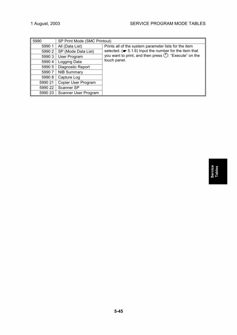
1 August, 2003 SERVICE PROGRAM MODE TABLES
5-45
Serv
ice
Tabl
es
5990 SP Print Mode (SMC Printout)
5990 1 All (Data List) 5990 2 SP (Mode Data List) 5990 3 User Program 5990 4 Logging Data 5990 5 Diagnostic Report 5990 7 NIB Summary 5990 8 Capture Log
5990 21 Copier User Program 5990 22 Scanner SP 5990 23 Scanner User Program
Prints all of the system parameter lists for the item selected. (☛ 5.1.6) Input the number for the item that you want to print, and then press #: �Execute� on the touch panel.

SERVICE PROGRAM MODE TABLES 1 August, 2003
5-46
SP6-xxx: Peripherals ADF Registration Adjustment 6006* Adjusts the side-to-side and leading edge registration for simplex and duplex original feeding in ARDF mode. Press ! to toggle ±. SP6006 5 sets the maximum setting allowed for rear edge erase.
6006 1* Side-to-side [�3 ~ +3 / 0.0 / 0.1 mm step] 6006 2* Leading Edge (Thin Original) [�30 ~ +30 / 0.0 / 0.17 mm step] 6006 3* Leading Edge (Duplex Front) [�42 ~ +42 / 0.0 / 0.12 mm step] 6006 4* Leading Edge (Duplex Rear) [�42 ~ +42 / 0.0 / 0.12 mm step] 6006 5* Rear Edge Erase [�20 ~ +20 / 0.0 / 0.5 mm step]
6007 ADF Input Check
6007 1 Group 1 6007 2 Group 2 6007 3 Group 3
Displays the signals received from sensors and switches of the ARDF.( ☛ 5.1.4)
ADF Output Check 6008 Switches on each electrical component (ARDF motor, solenoid, etc.) of the ARDF for testing. (☛ 5.1.5)
ADF Free Run 6009 Performs a free run with the ARDF for duplex and stamp testing. Input the number for the item you want to check, and then press # to start. This is a general free run controlled from the copier. For more detailed free run modes, see the ARDF manual.
6009 1 Duplex Mode OFF/ON 6009 2 Stamp Mode OFF/ON
ADF Stamp Position Adjustment [�7~+7 / 0 / 0.5 mm steps] 6010* Adjusts the horizontal position of the stamp on the scanned originals.
Japan Bit 0 1 7 DLT SEF 11"x15" North America Bit 0 1 6 DLT SEF 11" x 15" 5 LT LEF US Exec LEF 4 LT SEF 8"x10" SEF 3 LG SEF F4 SEF Europe Bit 0 1 2 DLT SEF 8-K SEF 1 LT SEF 16-K SEF
Original Size Decision Priority
0 LT LEF 16-K LEF
6016*
Determines which original sizes are detected when an original is detected that is larger than the size assigned to the original size sensor. This provides an alternate selection for detection, other than that assigned with SP5131.

1 August, 2003 SERVICE PROGRAM MODE TABLES
5-47
Serv
ice
Tabl
es
Sheet Through Magnification [�50.0 ~ +50.0 / 0.0 / 0.1%/step] 6017* Adjusts the magnification in the sub-scan direction for ADF mode. Use the ! key to toggle between + and - before entering the value
Staple Position Adjustment [�3.5~+3.5 / 0.0 / 0.5 mm step] 6105* Adjusts the staple position in the main scan direction when using the two-tray finisher. Press ! to toggle ±. A larger value shifts the staple toward the edge of the paper.
Punch Hole Adjustment 6113* Adjusts the punch hole position. SP6113 1: 2-hole punches for Japan, North America, Europe, and 4-hole punches for Northern Europe. SP6113 2: 3-hole punches for North America, and 4-hole punches for Europe. Press ! to toggle ±. A larger value shifts the holes toward the edge of the paper.
6113 1* 2-Holes [�7~+7 / 0 / 0.5 mm steps] 6113 2* 3-Holes [�7~+7 / 0 / 0.5 mm steps]
Fold Position Adjustment 6902* Allows fine adjustment of the fold position on paper when the Booklet Finisher is connected and used.
6902 1* A3/DLT [-30~+30 / 0 / 0.5 mm] 6902 2* B4 [-20~+20 / 0 / 0.5 mm] 6902 3* A4/LT [-15~+15 / 0 / 0.5 mm]

SERVICE PROGRAM MODE TABLES 1 August, 2003
5-48
SP7-xxx: Data Log Main Motor Operation Time Display: 00000000~99999999 min 7001* The number of prints and drive time for drum revolutions can be obtained by counting the main motor revolution time. If the amount of time required for the drum to revolve to print 1 copy increases, this data combined with the number of copies can be used to analyze problems and could be useful for future product development.
7002* Original Counter
7002 1* Total 7002 2* Copier 7002 3* Fax 7002 4* Doc. Svr. Application 7002 5* Scanner 7002 6* Others
Select a number to display the total original count (number of originals fed) for the selected item.
7003* Print Counter
7003 1* Total Count 7003 2* Copy 7003 3* Fax 7003 4* Printer 7003 5* Others
Select a number to display the total print count for the selected item.
C/O, P/O Counter 7006* Displays the number of copies/prints per original when making more than 10 copies. For example, if you make 15 copies of a 3 page original document, for a total of 45 sheets, then the counter would be 15 (5 copies counted from 11 to 15 x 3 originals). No count will be returned for 1~10 copies of an original.
7006 1* C/O (Copies/Original) 7006 2* P/O (Prints/Original)
Displays number
7007* Other Counters
7007 1* Duplex Counter 7007 2* A3/DLT Counter 7007 3* Staple Counter 7007 4* Scan Counter
Displays the count total for the selected item.

1 August, 2003 SERVICE PROGRAM MODE TABLES
5-49
Serv
ice
Tabl
es
7101* Print Count: Paper Size
7101 5* A4 LEF 7101 6* A5 LEF
7101 14* B5 LEF 7101 38* LT LEF 7101 44* HLT LEF
7101 132* A3 SEF 7101 133* A4 SEF 7101 134* A5 SEF 7101 141* B4 SEF 7101 142* B5 SEF 7101 160* DLT SEF 7101 164* LG SEF 7101 166* LT SEF 7101 172* HLT SEF
Displays the total number of prints by paper size.
7101 255* Other Count for custom (non-standard) paper sizes 7105* P type Counter
7105 1* Normal 7105 2* Recycled 7105 3* Special 7105 4* Colour 7105 6* Letterhead 7105 7* Label 7105 8* Thick 7105 9* OHP
7105 10* Used 7105 11* Index
7105 255* Others
Displays the count for each type of special paper, up to 99,999,999.
7201* Total Scan Counter Displays the total number of originals scanned.
Print Counter - Paper Tray 7204* Displays the total number of sheets fed from each paper feed tray.
7204 1* ByPass Copier 7204 2* Tray 1 Copier 7204 3* Tray 2 Copier 7204 4* Tray 3 Paper Tray Unit (Option) 7204 5* Tray 4 Paper Tray Unit (Option) 7204 6* LCT Large Capacity Tray (Option)
7205* Total ADF Counter Displays the total number of originals fed by the ARDF.
7206* Staple Counter
7206 1* Normal Staple 7206 2* Binding Staple
Display the total number of staples fired.

SERVICE PROGRAM MODE TABLES 1 August, 2003
5-50
7209* Punch Displays the total times the punch has fired.
7401* Total SC Counter Displays the total number of service calls that have
occurred. Display range: 0000~9999 7403* SC History
7403 1* Latest 7403 2* Latest 1 7403 3* Latest 2 7403 4* Latest 3 7403 5* Latest 4 7403 6* Latest 5 7403 7* Latest 6 7403 8* Latest 7 7403 9* Latest 8
7403 10* Latest 9
Displays the most recent service calls successive groups of 10.
7502* Total Paper Jam
Counter Displays the total number of copy jams. Display range: 0000~9999
7503* Total Original Jam
Counter Displays the total number of original jams. Display range: 0000~9999
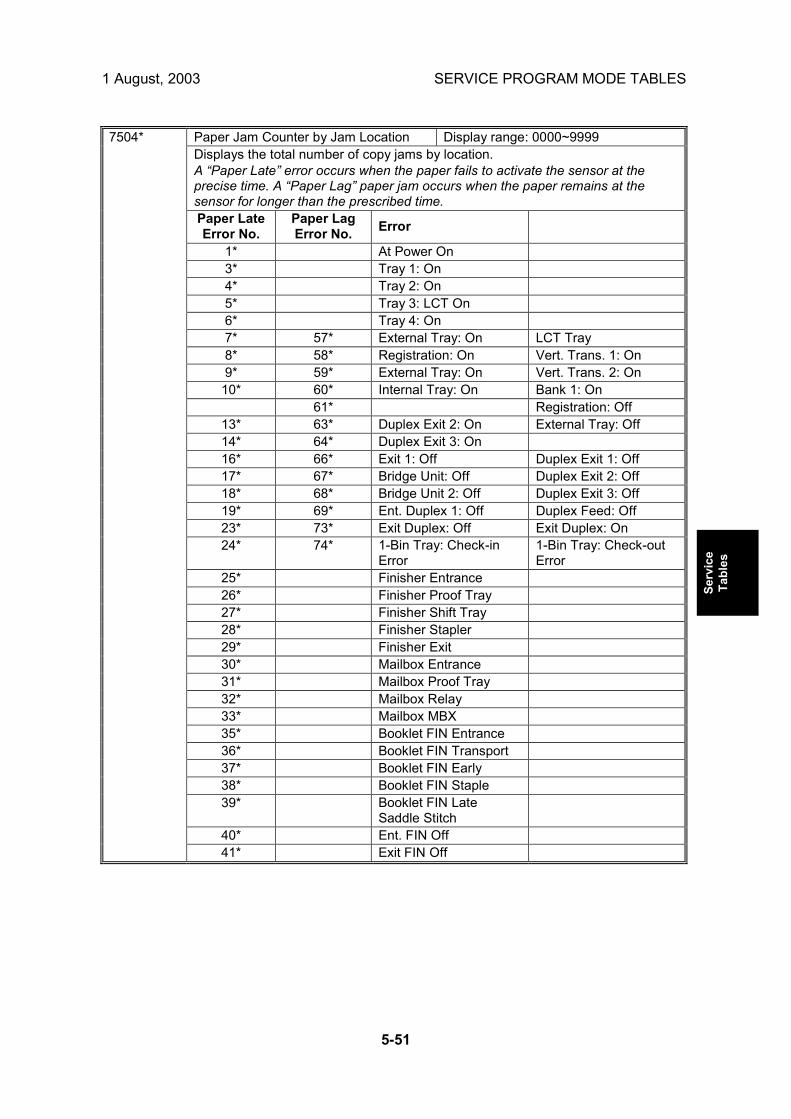
1 August, 2003 SERVICE PROGRAM MODE TABLES
5-51
Serv
ice
Tabl
es
Paper Jam Counter by Jam Location Display range: 0000~9999 Displays the total number of copy jams by location. A �Paper Late� error occurs when the paper fails to activate the sensor at the precise time. A �Paper Lag� paper jam occurs when the paper remains at the sensor for longer than the prescribed time. Paper Late Error No.
Paper Lag Error No. Error
1* At Power On 3* Tray 1: On 4* Tray 2: On 5* Tray 3: LCT On 6* Tray 4: On 7* 57* External Tray: On LCT Tray 8* 58* Registration: On Vert. Trans. 1: On 9* 59* External Tray: On Vert. Trans. 2: On 10* 60* Internal Tray: On Bank 1: On
61* Registration: Off 13* 63* Duplex Exit 2: On External Tray: Off 14* 64* Duplex Exit 3: On 16* 66* Exit 1: Off Duplex Exit 1: Off 17* 67* Bridge Unit: Off Duplex Exit 2: Off 18* 68* Bridge Unit 2: Off Duplex Exit 3: Off 19* 69* Ent. Duplex 1: Off Duplex Feed: Off 23* 73* Exit Duplex: Off Exit Duplex: On 24* 74* 1-Bin Tray: Check-in
Error 1-Bin Tray: Check-out Error
25* Finisher Entrance 26* Finisher Proof Tray 27* Finisher Shift Tray 28* Finisher Stapler 29* Finisher Exit 30* Mailbox Entrance 31* Mailbox Proof Tray 32* Mailbox Relay 33* Mailbox MBX 35* Booklet FIN Entrance 36* Booklet FIN Transport 37* Booklet FIN Early 38* Booklet FIN Staple 39* Booklet FIN Late
Saddle Stitch
40* Ent. FIN Off
7504*
41* Exit FIN Off

SERVICE PROGRAM MODE TABLES 1 August, 2003
5-52
Total Original Jam by Location Display range: 0000~9999 Displays the total number of original jams by location. These jams occur when the original does not activate the sensors. A �Paper Late� error occurs when the paper fails to activate the sensor at the precise time. A �Paper Linger� paper jam occurs when the paper remains at the sensor for longer than the prescribed time.
1* At Power On Paper Late Error
No. Paper Lag Error No. Error Location
3 53 Skew Correction Sensor 4 54 Interval Sensor 5 55 Registration Sensor 6 56 Relay Sensor
7505*
7 57 Inverter Sensor 7506* Jam Count by Copy Size
7506 5* A4 LEF 7506 6* A5 LEF
7506 14* B5 LEF 7506 38* LT LEF 7506 44* HLT LEF
7506 132* A3 SEF 7506 133* A4 SEF 7506 134* A5 SEF 7506 141* B4 SEF 7506 142* B5 SEF 7506 160* DLT SEF 7506 164* LG SEF 7506 166* LT SEF 7506 172* HLT SEF 7506 255* Others
Displays the total number of copy jams by paper size.
Copy Jam History (Transfer Sheet) 7507* Displays the copy jam history of the transfer unit in groups of 10, starting with the most recent 10 jams. Display contents are as follows: CODE is the SP7-505-*** number. SIZE is the paper size code in hex. (See �Paper Size Hex Codes� below.) TOTAL is the total jam error count (SP7-003) DATE is the date the previous jam occurred
7507 1* Latest 7507 2* Latest 1 7507 3* Latest 2 7507 4* Latest 3 7507 5* Latest 4 7507 6* Latest 5 7507 7* Latest 6 7507 8* Latest 7 7507 9* Latest 8
7507 10* Latest 9
Sample Display: CODE: 007 SIZE: 05h TOTAL: 0000334 DATE: Mon Mar 15 11:44:50 2000

1 August, 2003 SERVICE PROGRAM MODE TABLES
5-53
Serv
ice
Tabl
es
Original Jam History 7508* Displays the original jam history of the transfer unit in groups of 10, starting with the most recent 10 jams. Display contents are as follows: CODE is the SP7-505-*** number. SIZE is the paper size code in hex. (See �Paper Size Hex Codes� below.) TOTAL is the total jam error count (SP7-003) DATE is the date the previous jam occurred
7508 1* Latest 7508 2* Latest 1 7508 3* Latest 2 7508 4* Latest 3 7508 5* Latest 4 7508 6* Latest 5 7508 7* Latest 6 7508 8* Latest 7 7508 9* Latest 8
7508 10* Latest 9
Sample Display: CODE: 007 SIZE: 05h TOTAL: 0000334 DATE: Mon Mar 15 11:44:50 2000
Paper Size Hex Codes These codes are displayed by SP7507 and SP7508.Paper Size Code (hex) A4 LEF 05 A5 LEF 06 B5 LEF 0E LT LEF 26 HLT LEF 2C A3 SEF 84 A4 SEF 85 A5 SEF 86 B4 SEF 8D B5 SEF 8E DLT SEF A0 LG SEF A4 LT SEF A6 HLT SEF AC Others FF

SERVICE PROGRAM MODE TABLES 1 August, 2003
5-54
7801 ROM No./Firmware
Version Displays the ROM number and firmware version numbers.
7803* PM Counter Display Displays the PM counter since the last PM.
7804 PM Counter Reset Resets the PM counter. To reset, press #.
SC/Jam Counter Reset Resets the SC and jam counters. To reset, press #. 7807 This SP does not reset the jam history counters: SP7-507, SP7-508.
7808 Counter Reset Resets all counters except SP7-003-***, SP7-006-***.
To reset, press #.
Access Code Clear Clears the access code. To clear, press #. 7810 Use to clear the access code if the customer forgets the code. After clearing the code is reset for Null and the password entry display does not open.
7811 Original Count Clear Clears the original total display, displayed with SP7-
002-***. To clear, press #. 7816 Print Counter Reset by Tray
7816 1 Bypass 7816 2 Tray 1 7816 3 Tray 2 7816 4 Tray 3 7816 5 Tray 4 7816 6 LCT
Resets the total copy count by paper tray. To reset, press #. Use these SP modes when replacing the pick-up, feed, and separation rollers.
7825 Total Counter Reset No longer used. (Has no effect)
7826* MF Error Counter Japan Only
7827 MF Device Error Counter Clear Japan Only
Self-Diagnosis Result Display Opens the �Self-Diagnose Result Display� 7832 Execute to open the �Self-Diagnose Result Display� to view details about errors. Use the keys on in the display on the touch-panel to scroll through all the information. If no errors have occurred, you will see the �No Error� notation.

1 August, 2003 SERVICE PROGRAM MODE TABLES
5-55
Serv
ice
Tabl
es
Pixel Coverage Ratio 7833 Displays the coverage ratio of the output (the ratio of the total pixel area of the image data to the total printable area on the paper). Note that this value is not directly proportional to the amount of toner consumed, although of course it is one factor that affects this amount. The other major factors involved include: the type, total image area and image density of the original, toner concentration and developer potential.
7833 1* Last Pages 0% to 100%. 7833 2* Average Pages 0% to 100%. 7833 3* Toner Bottles In Use 0 to 65,535 copies 7833 4* Copy Count: Previous Toner Bottle 0 to 999,999 copies 7833 5* Copy Count: Toner Bottle Before Previous 0 to 999,999 copies
7834 Clear Pixel Coverage Data
These SPs clear the counters of SP7833 (see table above). 7834 1 Last & Average Clears counter for SP7833 001, 002 7834 2 Toner Bottles In Use Clears counter for SP7833 003 7834 3 Page Counts (2 Prev. Toner Bottles) Clears counter for SP7833 004, 005
7836 Total Memory Size Displays the memory capacity of the controller system.
7852 ADF Scan Glass Dust Check Counter Counts the number of occurrences (0 ~ 65,535) when dust was detected on the
scanning glass of the ADF. Counting is done only if SP4991 1 (ADF Scan Glass Dust Check) is switched on. Memory All Clear (SP5801) resets this counter to zeror
7901* Assert Info. DFU
These SP numbers display the results of the occurrence of the most recent SC code generated by the machine.
7991 1* Source File Name Module name 7991 2* Line Number Number of lines 7991 3* Result Value

SERVICE PROGRAM MODE TABLES 1 August, 2003
5-56
SP8-xxx: Data Log2 Many of these counters are provided for features that are currently not available, such as sending color faxes, and so on. However, here are some Group 8 codes that when used in combination with others, can provide useful information.
SP Numbers What They Do SP8 211~SP8 216 The number of pages scanned to the document server. SP8 401~SP8 406 The number of pages printed from the document server SP8 691~SP8 696 The number of pages sent from the document server
Specifically, the following questions can be answered: • How is the document server actually being used? • What application is using the document server most frequently? • What data in the document server is being reused? Most of the SPs in this group are prefixed with a letter that indicates the mode of operation (the mode of operation is referred to as an �application�). Before reading the Group 8 Service Table, make sure that you understand what these prefixes mean.
PREFIXES WHAT IT MEANS T: Total: (Grand Total). Grand total of the items counted for all
applications (C, F, P, etc.).. C: Copy application. F: Fax application. P: Print application. S: Scan application.
Totals (pages, jobs, etc.) executed for each application when the job was not stored on the document server.
L: Local storage (document server)
Totals (jobs, pages, etc.) for the document server. The L: counters work differently case by case. Sometimes, they count jobs/pages stored on the document server; this can be in document server mode (from the document server window), or from another mode, such as from a printer driver or by pressing the Store File button in the Copy mode window. Sometimes, they include occasions when the user uses a file that is already on the document server. Each counter will be discussed case by case.
O: Other applications (external network applications, for example)
Refers to network applications such as Web Image Monitor. Utilities developed with the SDK (Software Development Kit) will also be counted with this group in the future.
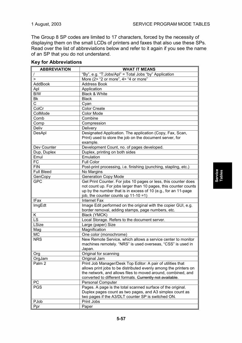
1 August, 2003 SERVICE PROGRAM MODE TABLES
5-57
Serv
ice
Tabl
es
The Group 8 SP codes are limited to 17 characters, forced by the necessity of displaying them on the small LCDs of printers and faxes that also use these SPs. Read over the list of abbreviations below and refer to it again if you see the name of an SP that you do not understand. Key for Abbreviations
ABBREVIATION WHAT IT MEANS / �By�, e.g. �T:Jobs/Apl� = Total Jobs �by� Application > More (2> �2 or more�, 4> �4 or more� AddBook Address Book Apl Application B/W Black & White Bk Black C Cyan ColCr Color Create ColMode Color Mode Comb Combine Comp Compression Deliv Delivery DesApl Designated Application. The application (Copy, Fax, Scan,
Print) used to store the job on the document server, for example.
Dev Counter Development Count, no. of pages developed. Dup, Duplex Duplex, printing on both sides Emul Emulation FC Full Color FIN Post-print processing, i.e. finishing (punching, stapling, etc.) Full Bleed No Margins GenCopy Generation Copy Mode GPC Get Print Counter. For jobs 10 pages or less, this counter does
not count up. For jobs larger than 10 pages, this counter counts up by the number that is in excess of 10 (e.g., for an 11-page job, the counter counts up 11-10 =1)
IFax Internet Fax ImgEdt Image Edit performed on the original with the copier GUI, e.g.
border removal, adding stamps, page numbers, etc. K Black (YMCK) LS Local Storage. Refers to the document server. LSize Large (paper) Size Mag Magnification MC One color (monochrome) NRS New Remote Service, which allows a service center to monitor
machines remotely. �NRS� is used overseas, �CSS� is used in Japan.
Org Original for scanning OrgJam Original Jam Palm 2 Print Job Manager/Desk Top Editor: A pair of utilities that
allows print jobs to be distributed evenly among the printers on the network, and allows files to moved around, combined, and converted to different formats. Currently not available.
PC Personal Computer PGS Pages. A page is the total scanned surface of the original.
Duplex pages count as two pages, and A3 simplex count as two pages if the A3/DLT counter SP is switched ON.
PJob Print Jobs Ppr Paper

SERVICE PROGRAM MODE TABLES 1 August, 2003
5-58
ABBREVIATION WHAT IT MEANS PrtJam Printer (plotter) Jam PrtPGS Print Pages R Red (Toner Remaining). Applies to the wide format model A2
only. This machine is under development and currently not available.
Rez Resolution SC Service Code (Error SC code displayed) Scn Scan Sim, Simplex Simplex, printing on 1 side. S-to-Email Scan-to-E-mail SMC SMC report printed with SP5990. All of the Group 8 counters
are recorded in the SMC report. Svr Server TonEnd Toner End TonSave Toner Save TXJob Send, Transmission YMC Yellow, Magenta, Cyan YMCK Yellow, Magenta, Cyan, BlacK
NOTE: All of the Group 8 SPs are reset with SP5 801 1 Memory All Clear, or the
Counter Reset SP7 808.

1 August, 2003 SERVICE PROGRAM MODE TABLES
5-59
Serv
ice
Tabl
es
8 001 T:Total Jobs 8 002 C:Total Jobs 8 003 F:Total Jobs 8 004 P:Total Jobs 8 005 S:Total Jobs 8 006 L:Total Jobs 8 007 O:Total Jobs
These SPs count the number of times each application is used to do a job. [0~9999999/ 0 / 1] Note: The L: counter is the total number of times the other applications are used to send a job to the document server, plus the number of times a file already on the document server is used.
• These SPs reveal the number of times an application is used, not the number of
pages processed. • When an application is opened for image input or output, this counts as one job. • Interrupted jobs (paper jams, etc.) are counted, even though they do not finish. • Only jobs executed by the customer are counted. Jobs executed by the customer
engineer using the SP modes are not counted. • When using secure printing (when a password is required to start the print job),
the job is counted at the time when either �Delete Data� or �Specify Output� is specified.
• A job is counted as a fax job when the job is stored for sending. • When a fax is received to fax memory, the F: counter increments but the L:
counter does not (the document server is not used). • A fax broadcast counts as one job for the F: counter (the fax destinations in the
broadcast are not counted separately). • A fax broadcast is counted only after all the faxes have been sent to their
destinations. If one transmission generates an error, then the broadcast will not be counted until the transmission has been completed.
• A printed fax report counts as one job for the F: counter. • The F: counter does not distinguish between fax sending or receiving. • When a copy job on the document server is printed, SP8022 also increments,
and when a print job stored on the document server is printed, SP8024 also increments.
• When an original is both copied and stored on the document server, the C: and L: counters both increment.
• When a print job is stored on the document server, only the L: counter increments.
• When the user presses the Document Server button to store the job on the document server, only the L: counter increments.
• When the user enters document server mode and prints data stored on the document server, only the L: counter increments.
• When an image received from Palm 2 is received and stored, the L: counter increments.
• When the customer prints a report (user code list, for example), the O: counter increments. However, for fax reports and reports executed from the fax application, the F: counter increments.

SERVICE PROGRAM MODE TABLES 1 August, 2003
5-60
8 011 T:Jobs/LS 8 012 C:Jobs/LS 8 013 F:Jobs/LS 8 014 P:Jobs/LS 8 015 S:Jobs/LS 8 016 L:Jobs/LS 8 017 O:Jobs/LS
These SPs count the number of jobs stored to the document server by each application, to reveal how local storage is being used for input. [0~9999999/ 0 / 1] The L: counter counts the number of jobs stored from within the document server mode screen at the operation panel.
• When a scan job is sent to the document server, the S: counter increments.
When you enter document server mode and then scan an original, the L: counter increments.
• When a print job is sent to the document server, the P: counter increments. • When a network application sends data to the document server, the O: counter
increments. • When an image from Palm 2 is stored on the document server, the O: counter
increments. • When a fax is sent to the document server, the F: counter increments.
8 021 T:Pjob/LS 8 022 C:Pjob/LS 8 023 F:Pjob/LS 8 024 P:Pjob/LS 8 025 S:Pjob/LS 8 026 L:Pjob/LS 8 027 O:Pjob/LS
These SPs reveal how files printed from the document server were stored on the document server originally. [0~9999999/ 0 / 1] The L: counter counts the number of jobs stored from within the document server mode screen at the operation panel.
• When a copy job stored on the document server is printed with another
application, the C: counter increments. • When an application like DeskTopBinder merges a copy job that was stored on
the document server with a print job that was stored on the document server, the C: and P: counters both increment.
• When a job already on the document server is printed with another application, the L: counter increments.
• When a scanner job stored on the document server is printed with another application, the S: counter increments. If the original was scanned from within document server mode, then the L: counter increments.
• When images stored on the document server by a network application (including Palm 2), are printed with another application, the O: counter increments.
• When a copy job stored on the document server is printed with a network application (Web Image Monitor, for example), the C: counter increments.
• When a fax on the document server is printed, the F: counter increments.

1 August, 2003 SERVICE PROGRAM MODE TABLES
5-61
Serv
ice
Tabl
es
8 031 T:Pjob/DesApl 8 032 C:Pjob/DesApl 8 033 F:Pjob/DesApl 8 034 P:Pjob/DesApl 8 035 S:Pjob/DesApl 8 036 L:Pjob/DesApl 8 037 O:Pjob/DesApl
These SPs reveal what applications were used to output documents from the document server. [0~9999999/ 0 / 1] The L: counter counts the number of jobs printed from within the document server mode screen at the operation panel.
• When documents already stored on the document server are printed, the count
for the application that started the print job is incremented. • When the print job is started from a network application (Desk Top Binder, Web
Image Monitor, etc.) the L: counter increments.
8 041 T:TX Jobs/LS 8 042 C:TX Jobs/LS 8 043 F:TX Jobs/LS 8 044 P:TX Jobs/LS 8 045 S:TX Jobs/LS 8 046 L:TX Jobs/LS 8 047 O:TX Jobs/LS
These SPs count the applications that stored files on the document server that were later accessed for transmission over the telephone line or over a network (attached to an e-mail, or as a fax image by I-Fax). [0~9999999/ 0 / 1] Note: Jobs merged for sending are counted separately. The L: counter counts the number of jobs scanned from within the document server mode screen at the operation panel.
• When a stored copy job is sent from the document server, the C: counter
increments. • When images stored on the document server by a network application or Palm2
are sent as an e-mail, the O: counter increments.
8 051 T:TX Jobs/DesApl 8 052 C:TX Jobs/DesApl 8 053 F:TX Jobs/DesApl 8 054 P:TX Jobs/DesApl 8 055 S:TX Jobs/DesApl 8 056 L:TX Jobs/DesApl 8 057 O:TX Jobs/DesApl
These SPs count the applications used to send files from the document server over the telephone line or over a network (attached to an e-mail, or as a fax image by I-Fax). Jobs merged for sending are counted separately. [0~9999999/ 0 / 1] The L: counter counts the number of jobs sent from within the document server mode screen at the operation panel.
• If the send is started from Desk Top Binder or Web Image Monitor, for example,
then the O: counter increments.

SERVICE PROGRAM MODE TABLES 1 August, 2003
5-62
T:FIN Jobs [0~9999999/ 0 / 1] 8 061 These SPs total the finishing methods. The finishing method is specified by the application.
C:FIN Jobs [0~9999999/ 0 / 1] 8 062 These SPs total finishing methods for copy jobs only. The finishing method is specified by the application.
F:FIN Jobs [0~9999999/ 0 / 1] 8 063 These SPs total finishing methods for fax jobs only. The finishing method is specified by the application. Note: Finishing features for fax jobs are not available at this time. P:FIN Jobs [0~9999999/ 0 / 1] 8 064 These SPs total finishing methods for print jobs only. The finishing method is specified by the application. S:FIN Jobs [0~9999999/ 0 / 1] 8 065 These SPs total finishing methods for scan jobs only. The finishing method is specified by the application. Note: Finishing features for scan jobs are not available at this time. L:FIN Jobs [0~9999999/ 0 / 1] 8 066 These SPs total finishing methods for jobs output from within the document server mode screen at the operation panel. The finishing method is specified from the print window within document server mode.
O:FIN Jobs [0~9999999/ 0 / 1] 8 067 These SPs total finishing methods for jobs executed by an external application, over the network. The finishing method is specified by the application.
8 06x 1 Sort Number of jobs started in Sort mode. When a stored copy job is set for Sort and then stored on the document server, the L: counter increments. (See SP8 066 1)
8 06x 2 Stack Number of jobs started out of Sort mode. 8 06x 3 Staple Number of jobs started in Staple mode. 8 06x 4 Bookle
t Number of jobs started in Booklet mode. If the machine is in staple mode, the Staple counter also increments.
8 06x 5 Z-Fold Number of jobs started In any mode other than the Booklet mode and set for folding (Z-fold).
8 06x 6 Punch Number of jobs started in Punch mode. When Punch is set for a print job, the P: counter increments. (See SP8 064 6.)
8 06x 7 Other Reserved. Not used.

1 August, 2003 SERVICE PROGRAM MODE TABLES
5-63
Serv
ice
Tabl
es
T:Jobs/PGS [0~9999999/ 0 / 1] 8 071 These SPs count the number of jobs broken down by the number of pages in the job, regardless of which application was used. C:Jobs/PGS [0~9999999/ 0 / 1] 8 072 These SPs count and calculate the number of copy jobs by size based on the number of pages in the job. F:Jobs/PGS [0~9999999/ 0 / 1] 8 073 These SPs count and calculate the number of fax jobs by size based on the number of pages in the job. P:Jobs/PGS [0~9999999/ 0 / 1] 8 074 These SPs count and calculate the number of print jobs by size based on the number of pages in the job. S:Jobs/PGS [0~9999999/ 0 / 1] 8 075 These SPs count and calculate the number of scan jobs by size based on the number of pages in the job. L:Jobs/PGS [0~9999999/ 0 / 1] 8 076 These SPs count and calculate the number of jobs printed from within the document server mode window at the operation panel, by the number of pages in the job. O:Jobs/PGS [0~9999999/ 0 / 1] 8 077 These SPs count and calculate the number of �Other� application jobs (Web Image Monitor, Palm 2, etc.) by size based on the number of pages in the job.
8 07x 1 1 Page 8 07x 8 21~50 Pages 8 07x 2 2 Pages 8 07x 9 51~100 Pages 8 07x 3 3 Pages 8 07x 10 101~300 Pages 8 07x 4 4 Pages 8 07x 11 301~500 Pages 8 07x 5 5 Pages 8 07x 12 501~700 Pages 8 07x 6 6~10 Pages 8 07x 13 701~1000 Pages 8 07x 7 11~20 Pages 8 07x 14 1001~ Pages
• For example: When a copy job stored on the document server is printed in
document server mode, the appropriate L: counter (SP8076 0xx) increments. • Printing a fax report counts as a job and increments the F: counter (SP 8073). • Interrupted jobs (paper jam, etc.) are counted, even though they do not finish. • If a job is paused and re-started, it counts as one job. • If the finisher runs out of staples during a print and staple job, then the job is
counted at the time the error occurs. • For copy jobs (SP 8072) and scan jobs (SP 8075), the total is calculated by
multiplying the number of sets of copies by the number of pages scanned. (One duplex page counts as 2.)
• The first test print and subsequent test prints to adjust settings are added to the number of pages of the copy job (SP 8072).
• When printing the first page of a job from within the document server screen, the page is counted.

SERVICE PROGRAM MODE TABLES 1 August, 2003
5-64
T:FAX TX Jobs [0~9999999/ 0 / 1] 8 111 These SPs count the total number of jobs (color or black-and-white) sent by fax, either directly or using a file stored on the document server, on a telephone line. Note: Color fax sending is not available at this time. F:FAX TX Jobs [0~9999999/ 0 / 1] 8 113 These SPs count the total number of jobs (color or black-and-white) sent by fax directly on a telephone line. Note: Color fax sending is not available at this time. L:FAX TX Jobs [0~9999999/ 0 / 1] 8 116 These SPs count the total number of jobs (color or black-and-white) sent by fax on a telephone line using a file stored on the document server. Documents sent from fax memory are not counted. Note: Color fax sending is not available at this time.
• These counters count jobs, not pages. • This SP counts fax jobs sent over a telephone line with a fax application,
including documents stored on the document server. • If the mode is changed during the job, the job will count with the mode set when the
job started. • If the same document is faxed to both a public fax line and an I-Fax at a destination
where both are available, then this counter increments, and the I-Fax counter (8 12x) also increments.
• The fax job is counted when the job is scanned for sending, not when the job is sent.
T:IFAX TX Jobs [0~9999999/ 0 / 1] 8 121 These SPs count the total number of jobs (color or black-and-white) sent, either directly or using a file stored on the document server, as fax images using I-Fax. Note: Color fax sending is not available at this time. F:IFAX TX Jobs [0~9999999/ 0 / 1] 8 123 These SPs count the number of jobs (color or black-and-white) sent (not stored on the document server), as fax images using I-Fax. Note: Color fax sending is not available at this time. L:IFAX TX Jobs [0~9999999/ 0 / 1] 8 126 These SPs count the number of jobs (color or black-and-white) sent using a file stored on the document server , as fax images using I-Fax. Note: Color fax sending is not available at this time.
• These counters count jobs, not pages. • The counters for color are provided for future use; the color fax feature is not
available at this time. • The fax job is counted when the job is scanned for sending, not when the job is
sent.

1 August, 2003 SERVICE PROGRAM MODE TABLES
5-65
Serv
ice
Tabl
es
T:S-to-Email Jobs [0~9999999/ 0 / 1] 8 131 These SPs count the total number of jobs scanned and attached to an e-mail, regardless of whether the document server was used or not. S:S-to-Email Jobs 8 135 These SPs count the number of jobs scanned and attached to an e-mail, without storing the original on the document server. L:S-to-Email Jobs 8 136 These SPs count the number of jobs using a file stored on stored on the document server, and attaching it to an e-mail.
• These counters count jobs, not pages. • If the job is stored on the document server, after the job is stored it is determined
to be color or black-and-white then counted. • If the job is cancelled during scanning, or if the job is cancelled while the
document is waiting to be sent, the job is not counted. • If the job is cancelled during sending, it may or may not be counted, depending
on what stage of the process had been reached when the job was cancelled. • If several jobs are combined for sending to the Scan Router, Scan-to-Email, or
Scan-to-PC, or if one job is sent to more than one destination. each send is counted separately. For example, if the same document is sent by Scan-to-Email as well as Scan-to-PC, then it is counted twice (once for Scan-to-Email and once for Scan-to-PC).
T:Deliv Jobs/Svr [0~9999999/ 0 / 1] 8 141 These SPs count the total number of jobs scanned and sent to a Scan Router server. F:Deliv Jobs/Svr 8 143 These SPs count the number of jobs scanned in fax mode and sent to a Scan Router server. S:Deliv Jobs/Svr 8 145 These SPs count the number of jobs scanned in scanner mode and sent to a Scan Router server.
• These counters count jobs, not pages. • The jobs are counted even though the arrival and reception of the jobs at the
Scan Router server cannot be confirmed. • If even one color image is mixed with black-and-white images, then the job is
counted as a �Color� job. • If the job is cancelled during scanning, or if the job is cancelled while the
document is waiting to be delivered, the job is not counted. • If the job is cancelled during sending, it may or may not be counted, depending
on what stage of the process had been reached when the job was cancelled. • Even if several files are combined for sending, the transmission counts as one
job.
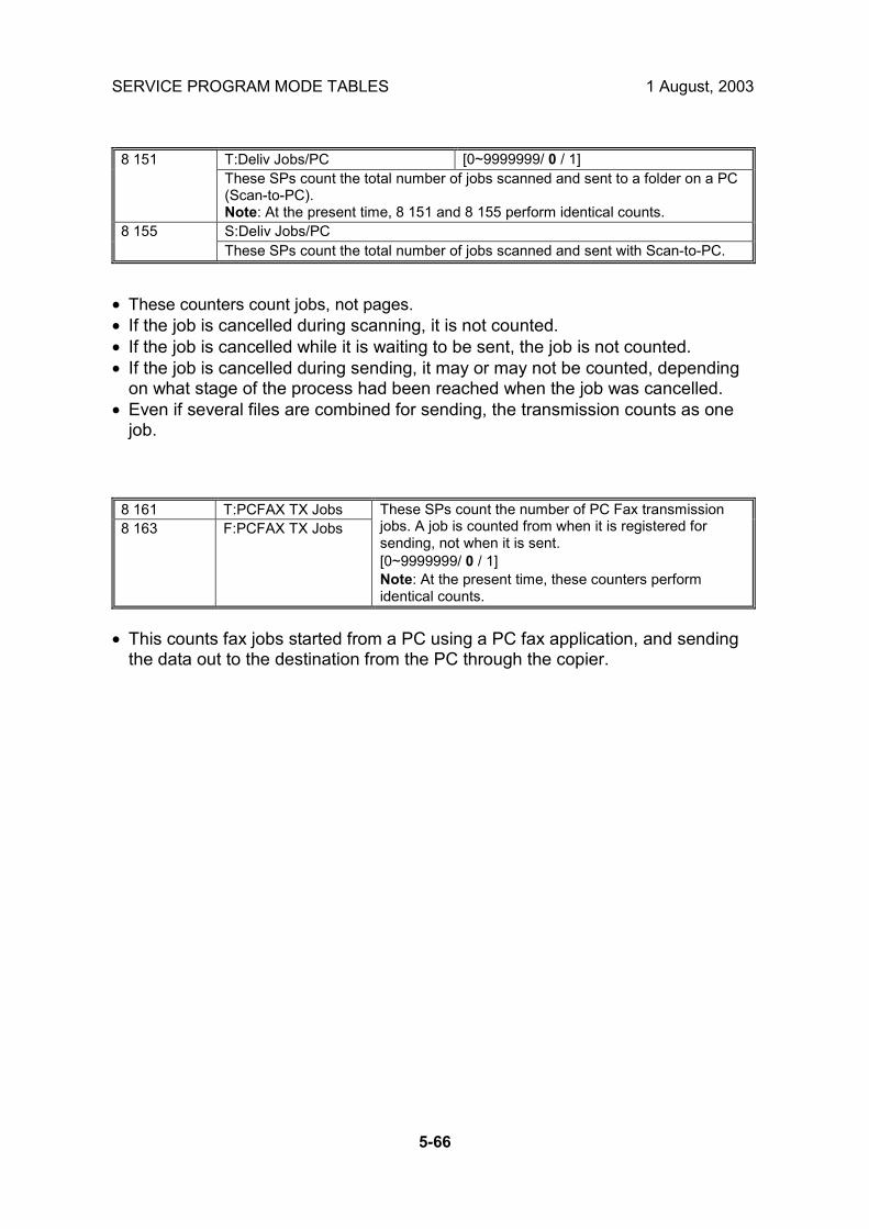
SERVICE PROGRAM MODE TABLES 1 August, 2003
5-66
T:Deliv Jobs/PC [0~9999999/ 0 / 1] 8 151 These SPs count the total number of jobs scanned and sent to a folder on a PC (Scan-to-PC). Note: At the present time, 8 151 and 8 155 perform identical counts. S:Deliv Jobs/PC 8 155 These SPs count the total number of jobs scanned and sent with Scan-to-PC.
• These counters count jobs, not pages. • If the job is cancelled during scanning, it is not counted. • If the job is cancelled while it is waiting to be sent, the job is not counted. • If the job is cancelled during sending, it may or may not be counted, depending
on what stage of the process had been reached when the job was cancelled. • Even if several files are combined for sending, the transmission counts as one
job.
8 161 T:PCFAX TX Jobs 8 163 F:PCFAX TX Jobs
These SPs count the number of PC Fax transmission jobs. A job is counted from when it is registered for sending, not when it is sent. [0~9999999/ 0 / 1] Note: At the present time, these counters perform identical counts.
• This counts fax jobs started from a PC using a PC fax application, and sending
the data out to the destination from the PC through the copier.

1 August, 2003 SERVICE PROGRAM MODE TABLES
5-67
Serv
ice
Tabl
es
8 191 T:Total Scan PGS 8 192 C:Total Scan PGS 8 193 F:Total Scan PGS 8 195 S:Total Scan PGS 8 196 L:Total Scan PGS
These SPs count the pages scanned by each application that uses the scanner to scan images. [0~9999999/ 0 / 1]
• SP 8 191 to 8 196 count the number of scanned sides of pages, not the number
of physical pages. • These counters do not count reading user stamp data, or reading color charts to
adjust color. • Previews done with a scanner driver are not counted. • A count is done only after all images of a job have been scanned. • Scans made in SP mode are not counted. Examples • If 3 B5 pages and 1 A3 page are scanned with the scanner application but not
stored, the S: count is 4. • If both sides of 3 A4 sheets are copied and stored to the document server using
the Store File button in the Copy mode window, the C: count is 6 and the L: count is 6.
• If both sides of 3 A4 sheets are copied but not stored, the C: count is 6. • If you enter document server mode then scan 6 pages, the L: count is 6.

SERVICE PROGRAM MODE TABLES 1 August, 2003
5-68
T:LSize Scan PGS [0~9999999/ 0 / 1] 8 201 These SPs count the total number of large pages input with the scanner for scan and copy jobs. Large size paper (A3/DLT) scanned for fax transmission are not counted. Note: These counters are displayed in the SMC Report, and in the User Tools display. S:LSize Scan PGS [0~9999999/ 0 / 1] 8 205 These SPs count the total number of large pages input with the scanner for scan jobs only. Large size paper (A3/DLT) scanned for fax transmission are not counted. Note: These counters are displayed in the SMC Report, and in the User Tools display..
8 211 T:Scan PGS/LS 8 212 C:Scan PGS/LS 8 213 F:Scan PGS/LS 8 215 S:Scan PGS/LS 8 216 L:Scan PGS/LS
These SPs count the number of pages scanned into the document server . [0~9999999/ 0 / 1] The L: counter counts the number of pages stored from within the document server mode screen at the operation panel, and with the Store File button from within the Copy mode screen
• Reading user stamp data is not counted. • If a job is cancelled, the pages output as far as the cancellation are counted. • If the scanner application scans and stores 3 B5 sheets and 1 A4 sheet, the S:
count is 4. • If pages are copied but not stored on the document server, these counters do not
change. • If both sides of 3 A4 sheets are copied and stored to the document server, the C:
count is 6 and the L: count is 6. • If you enter document server mode then scan 6 pages, the L: count is 6.

1 August, 2003 SERVICE PROGRAM MODE TABLES
5-69
Serv
ice
Tabl
es
ADF Org Feeds [0~9999999/ 0 / 1] 8 221 These SPs count the number of pages fed through the ADF for front and back side scanning.
8 221 1 Front Number of front sides fed for scanning: With an ADF that can scan both sides simultaneously, the Front side count is the same as the number of pages fed for either simplex or duplex scanning. With an ADF that cannot scan both sides simultaneously, the Front side count is the same as the number of pages fed for duplex front side scanning. (The front side is determined by which side the user loads face up.)
8 221 2 Back Number of rear sides fed for scanning: With an ADF that can scan both sides simultaneously, the Back count is the same as the number of pages fed for duplex scanning. With an ADF that cannot scan both sides simultaneously, the Back count is the same as the number of pages fed for duplex rear-side scanning.
• When 1 sheet is fed for duplex scanning the Front count is 1 and the Back count
is 1. • If a jam occurs during the job, recovery processing is not counted to avoid double
counting. Also, the pages are not counted if the jam occurs before the first sheet is output.
Scan PGS/Mode [0~9999999/ 0 / 1] 8 231 These SPs count the number of pages scanned by each ADF mode to determine the work load on the ADF.
8 231 1 Large Volume Selectable. Large copy jobs that cannot be loaded in the ADF at one time.
8 231 2 SADF Selectable. Feeding pages one by one through the ADF.
8 231 3 Mixed Size Selectable. Select �Mixed Sizes� on the operation panel.
8 231 4 Custom Size Selectable. Originals of non-standard size. 8 231 5 Platen Book mode. Raising the ADF and placing the original
directly on the platen. • If the scan mode is changed during the job, for example, if the user switches
from ADF to Platen mode, the count is done for the last selected mode. • The user cannot select mixed sizes or non-standard sizes with the fax application
so if the original�s page sizes are mixed or non-standard, these are not counted. • If the user selects �Mixed Sizes� for copying in the platen mode, the Mixed Size
count is enabled. • In the SADF mode if the user copies 1 page in platen mode and then copies 2
pages with SADF, the Platen count is 1 and the SADF count is 3.

SERVICE PROGRAM MODE TABLES 1 August, 2003
5-70
T:Scan PGS/Org [0~9999999/ 0 / 1] 8 241 These SPs count the total number of scanned pages by original type for all jobs, regardless of which application was used. C:Scan PGS/Org [0~9999999/ 0 / 1] 8 242 These SPs count the number of pages scanned by original type for Copy jobs. F:Scan PGS/Org [0~9999999/ 0 / 1] 8 243 These SPs count the number of pages scanned by original type for Fax jobs. S:Scan PGS/Org [0~9999999/ 0 / 1] 8 245 These SPs count the number of pages scanned by original type for Scan jobs. L:Scan PGS/Org [0~9999999/ 0 / 1] 8 246 These SPs count the number of pages scanned and stored from within the document server mode screen at the operation panel, and with the Store File button from within the Copy mode screen O:Scan PGS/Org [0~9999999/ 0 / 1] 8 247 These SPs count the number of pages scanned by original type by Other applications.
8 241 8 242 8 243 8 245 8 246 8 247 8 24x 1: Text Yes Yes Yes Yes Yes Yes 8 24x 2: Text/Photo Yes Yes Yes Yes Yes Yes 8 24x 3: Photo Yes Yes Yes Yes Yes Yes 8 24x 4: GenCopy, Pale Yes Yes No Yes Yes Yes 8 24x 5: Map Yes Yes No Yes Yes Yes 8 24x 6: Normal/Detail Yes No Yes No No No 8 24x 7: Fine/Super Fine Yes No Yes No No No 8 24x 8: Binary Yes No No Yes No No 8 24x 9: Grayscale Yes No No Yes No No
• If the scan mode is changed during the job, for example, if the user switches
from ADF to Platen mode, the count is done for the last selected mode.

1 August, 2003 SERVICE PROGRAM MODE TABLES
5-71
Serv
ice
Tabl
es
8 251 T:Scan PGS/ImgEdt 8 252 C:Scan PGS/ImgEdt 8 254 P:Scan PGS/ImgEdt 8 256 L:Scan PGS/ImgEdt 8 257 O:Scan PGS/ImgEdt
These SPs show how many times Image Edit features have been selected at the operation panel for each application. Some examples of these editing features are: • Erase> Border • Erase> Center • Image Repeat • Centering • Positive/Negative [0~9999999/ 0 / 1] Note: The count totals the number of times the edit features have been used. A detailed breakdown of exactly which features have been used is not given.
The L: counter counts the number of pages stored from within the document server mode screen at the operation panel, and with the Store File button from within the Copy mode screen.
8 281 T:Scan PGS/TWAIN 8 285 S:Scan PGS/TWAIN
These SPs count the number of pages scanned using a TWAIN driver. These counters reveal how the TWAIN driver is used for delivery functions. [0~9999999/ 0 / 1] Note: At the present time, these counters perform identical counts.
8 291 T:Scan PGS/Stamp 8 293 F:Scan PGS/Stamp 8 295 S:Scan PGS/Stamp 8 296 L:Scan PGS/Stamp
These SPs count the number of pages stamped with the stamp in the ADF unit. [0~9999999/ 0 / 1] The L: counter counts the number of pages stored from within the document server mode screen at the operation panel, and with the Store File button from within the Copy mode screen

SERVICE PROGRAM MODE TABLES 1 August, 2003
5-72
T:Scan PGS/Size [0~9999999/ 0 / 1] 8 301 These SPs count by size the total number of pages scanned by all applications. Use these totals to compare original page size (scanning) and output (printing) page size [SP 8-441]. C:Scan PGS/Size [0~9999999/ 0 / 1] 8 302 These SPs count by size the total number of pages scanned by the Copy application. Use these totals to compare original page size (scanning) and output (printing) page size [SP 8-442]. F:Scan PGS/Size [0~9999999/ 0 / 1] 8 303 These SPs count by size the total number of pages scanned by the Fax application. Use these totals to compare original page size (scanning) and output page size [SP 8-443]. S:Scan PGS/Size [0~9999999/ 0 / 1] 8 305 These SPs count by size the total number of pages scanned by the Scan application. Use these totals to compare original page size (scanning) and output page size [SP 8-445]. L:Scan PGS/Size [0~9999999/ 0 / 1] 8 306 These SPs count by size the total number of pages scanned and stored from within the document server mode screen at the operation panel, and with the Store File button from within the Copy mode screen. Use these totals to compare original page size (scanning) and output page size [SP 8-446].
8 30x 1 A3 8 30x 2 A4 8 30x 3 A5 8 30x 4 B4 8 30x 5 B5 8 30x 6 DLT 8 30x 7 LG 8 30x 8 LT 8 30x 9 HLT
8 30x 10 Full Bleed
8 30x 254 Other (Standard) 8 30x 255 Other (Custom)

1 August, 2003 SERVICE PROGRAM MODE TABLES
5-73
Serv
ice
Tabl
es
T:Scan PGS/Rez [0~9999999/ 0 / 1] 8 311 These SPs count by resolution setting the total number of pages scanned by applications that can specify resolution settings. S:Scan PGS/Rez [0~9999999/ 0 / 1] 8 315 These SPs count by resolution setting the total number of pages scanned by applications that can specify resolution settings. Note: At the present time, 8 311 and 8 315 perform identical counts.
8 31x 1 1200dpi ~ 8 31x 2 600dpi~1199dpi 8 31x 3 400dpi~599dpi 8 31x 4 200dpi~399dpi 8 31x 5 ~199dpi
• Copy resolution settings are fixed so they are not counted. • The Fax application does not allow finely-adjusted resolution settings so no count
is done for the Fax application.

SERVICE PROGRAM MODE TABLES 1 August, 2003
5-74
T:Scan PGS/Comp [0~9999999/ 0 / 1] 8 321 These SPs count by compression method the total number of pages scanned. S:Scan PGS/Comp [0~9999999/ 0 / 1] 8 325 These SPs count by compression method the total number of pages scanned by the Scan application. Note: At the present time, 8 321 and 8 325 perform identical counts.
8 32x 1 JPEG 8 32x 2 JPEG2000 8 32x 3 TIFF (Comp OFF) 8 32x 4 TIFF (Comp ON) 8 32x 5 PDF 8 32x 6 Other
8 381 T:Total PrtPGS 8 382 C:Total PrtPGS 8 383 F:Total PrtPGS 8 384 P:Total PrtPGS 8 385 S:Total PrtPGS 8 386 L:Total PrtPGS 8 387 O:Total PrtPGS
These SPs count the number of pages printed by the customer. The counter for the application used for storing the pages increments. [0~9999999/ 0 / 1] The L: counter counts the number of pages stored from within the document server mode screen at the operation panel. Pages stored with the Store File button from within the Copy mode screen go to the C: counter.
• When the A3/DLT double count function is switched on with SP5104, 1 A3/DLT
page is counted as 2. • When several documents are merged for a print job, the number of pages stored
are counted for the application that stored them. • These counters are used primarily to calculate charges on use of the machine,
so the following pages are not counted as printed pages: • Blank pages in a duplex printing job. • Blank pages inserted as document covers, chapter title sheets, and slip
sheets. • Reports printed to confirm counts. • All reports done in the service mode (service summaries, engine
maintenance reports, etc.) • Test prints for machine image adjustment. • Error notification reports. • Partially printed pages as the result of a copier jam.

1 August, 2003 SERVICE PROGRAM MODE TABLES
5-75
Serv
ice
Tabl
es
LSize PrtPGS [0~9999999/ 0 / 1] 8 391 These SPs count pages printed on paper sizes A3/DLT and larger. Note: In addition to being displayed in the SMC Report, these counters are also displayed in the User Tools display on the copy machine.
8 401 T:PrtPGS/LS 8 402 C:PrtPGS/LS 8 403 F:PrtPGS/LS 8 404 P:PrtPGS/LS 8 405 S:PrtPGS/LS 8 406 L:PrtPGS/LS
These SPs count the number of pages printed from the document server. The counter for the application used to print the pages is incremented. The L: counter counts the number of jobs stored from within the document server mode screen at the operation panel. [0~9999999/ 0 / 1]
• Print jobs done with Web Image Monitor and Desk Top Binder are added to the
L: count. • Fax jobs done with Web Image Monitor and Desk Top Binder are added to the F:
count.

SERVICE PROGRAM MODE TABLES 1 August, 2003
5-76
8 411 Prints/Duplex This SP counts the amount of paper (front/back counted
as 1 page) used for duplex printing. Last pages printed only on one side are not counted. [0~9999999/ 0 / 1]
T:PrtPGS/Dup Comb [0~9999999/ 0 / 1] 8 421 These SPs count by binding and combine, and n-Up settings the number of pages processed for printing. This is the total for all applications. C:PrtPGS/Dup Comb [0~9999999/ 0 / 1] 8 422 These SPs count by binding and combine, and n-Up settings the number of pages processed for printing by the copier application. F:PrtPGS/Dup Comb [0~9999999/ 0 / 1] 8 423 These SPs count by binding and combine, and n-Up settings the number of pages processed for printing by the fax application. P:PrtPGS/Dup Comb [0~9999999/ 0 / 1] 8 424 These SPs count by binding and combine, and n-Up settings the number of pages processed for printing by the printer application. S:PrtPGS/Dup Comb [0~9999999/ 0 / 1] 8 425 These SPs count by binding and combine, and n-Up settings the number of pages processed for printing by the scanner application. L:PrtPGS/Dup Comb [0~9999999/ 0 / 1] 8 426 These SPs count by binding and combine, and n-Up settings the number of pages processed for printing from within the document server mode window at the operation panel. O:PrtPGS/Dup Comb [0~9999999/ 0 / 1] 8 427 These SPs count by binding and combine, and n-Up settings the number of pages processed for printing by Other applications
8 42x 1 Simplex> Duplex 8 42x 2 Duplex> Duplex 8 42x 3 Book> Duplex 8 42x 4 Simplex Combine 8 42x 5 Duplex Combine 8 42x 6 2> 2 pages on 1 side (2-Up) 8 42x 7 4> 4 pages on 1 side (4-Up) 8 42x 8 6> 6 pages on 1 side (6-Up) 8 42x 9 8> 8 pages on 1 side (8-Up)
8 42x 10 9> 9 pages on 1 side (9-Up) 8 42x 11 16> 16 pages on 1 side (16-Up) 8 42x 12 Booklet 8 42x 13 Magazine
• These counts (SP8 421 to SP8 427) are especially useful for customers who
need to improve their compliance with ISO standards for the reduction of paper consumption.
• Pages that are only partially printed with the n-Up functions are counted as 1 page.
• Here is a summary of how the counters work for Booklet and Magazine modes:

1 August, 2003 SERVICE PROGRAM MODE TABLES
5-77
Serv
ice
Tabl
es
Booklet Magazine Original Pages Count Original
Pages Count
1 1 1 1 2 2 2 2 3 2 3 2 4 2 4 2 5 3 5 4 6 4 6 4 7 4 7 4 8 4 8 4
T:PrtPGS/ImgEdt [0~9999999/ 0 / 1] 8 431 These SPs count the total number of pages output with the three features below, regardless of which application was used. C:PrtPGS/ImgEdt [0~9999999/ 0 / 1] 8 432 These SPs count the total number of pages output with the three features below with the copy application. P:PrtPGS/ImgEdt [0~9999999/ 0 / 1] 8 434 These SPs count the total number of pages output with the three features below with the print application. L:PrtPGS/ImgEdt [0~9999999/ 0 / 1] 8 436 These SPs count the total number of pages output from within the document server mode window at the operation panel with the three features below. O:PrtPGS/ImgEdt [0~9999999/ 0 / 1] 8 437 These SPs count the total number of pages output with the three features below with Other applications.
8 43x 1 Cover/Slip Sheet Total number of covers or slip sheets inserted. The count for a cover printed on both sides counts 2.
8 43x 2 Series/Book The number of pages printed in series (one side) or printed as a book with booklet right/left pagination.
8 43x 3 User Stamp The number of pages printed where stamps were applied, including page numbering and date stamping.

SERVICE PROGRAM MODE TABLES 1 August, 2003
5-78
T:PrtPGS/Ppr Size [0~9999999/ 0 / 1] 8 441 These SPs count by print paper size the number of pages printed by all applications. C:PrtPGS/Ppr Size [0~9999999/ 0 / 1] 8 442 These SPs count by print paper size the number of pages printed by the copy application. F:PrtPGS/Ppr Size [0~9999999/ 0 / 1] 8 443 These SPs count by print paper size the number of pages printed by the fax application. P:PrtPGS/Ppr Size [0~9999999/ 0 / 1] 8 444 These SPs count by print paper size the number of pages printed by the printer application. S:PrtPGS/Ppr Size [0~9999999/ 0 / 1] 8 445 These SPs count by print paper size the number of pages printed by the scanner application. L:PrtPGS/Ppr Size [0~9999999/ 0 / 1] 8 446 These SPs count by print paper size the number of pages printed from within the document server mode window at the operation panel. O:PrtPGS/Ppr Size [0~9999999/ 0 / 1] 8 447 These SPs count by print paper size the number of pages printed by Other applications.
8 44x 1 A3 8 44x 2 A4 8 44x 3 A5 8 44x 4 B4 8 44x 5 B5 8 44x 6 DLT 8 44x 7 LG 8 44x 8 LT 8 44x 9 HLT
8 44x 10 Full Bleed
8 44x 254 Other (Standard) 8 44x 255 Other (Custom)
• These counters do not distinguish between LEF and SEF.

1 August, 2003 SERVICE PROGRAM MODE TABLES
5-79
Serv
ice
Tabl
es
PrtPGS/Ppr Tray [0~9999999/ 0 / 1] 8 451 These SPs count the number of sheets fed from each paper feed station.
8 451 1 Bypass Bypass Tray 8 451 2 Tray 1 Copier 8 451 3 Tray 2 Copier 8 451 4 Tray 3 Paper Tray Unit (Option) 8 451 5 Tray 4 Paper Tray Unit (Option) 8 451 6 Tray 5 LCT (Option) 8 451 7 Tray 6 Currently not used. 8 451 8 Tray 7 Currently not used. 8 451 9 Tray 8 Currently not used.
8 451 10 Tray 9 Currently not used.
T:PrtPGS/Ppr Type [0~9999999/ 0 / 1] 8 461 These SPs count by paper type the number pages printed by all applications. • These counters are not the same as the PM counter. The PM counter is
based on feed timing to accurately measure the service life of the feed rollers. However, these counts are based on output timing.
• Blank sheets (covers, chapter covers, slip sheets) are also counted. • During duplex printing, pages printed on both sides count as 1, and a
page printed on one side counts as 1. C:PrtPGS/Ppr Type [0~9999999/ 0 / 1] 8 462 These SPs count by paper type the number pages printed by the copy application. F:PrtPGS/Ppr Type [0~9999999/ 0 / 1] 8 463 These SPs count by paper type the number pages printed by the fax application. P:PrtPGS/Ppr Type [0~9999999/ 0 / 1] 8 464 These SPs count by paper type the number pages printed by the printer application. L:PrtPGS/Ppr Type [0~9999999/ 0 / 1] 8 466 These SPs count by paper type the number pages printed from within the document server mode window at the operation panel.
8 46x 1 Normal 8 46x 2 Recycled 8 46x 3 Special 8 46x 4 Thick 8 46x 5 Normal (Back) 8 46x 6 Thick (Back) 8 46x 7 OHP 8 46x 8 Other

SERVICE PROGRAM MODE TABLES 1 August, 2003
5-80
PrtPGS/Mag [0~9999999/ 0 / 1] 8 471 These SPs count by magnification rate the number of pages printed.
8 471 1 ~49% 8 471 2 50%~99% 8 471 3 100% 8 471 4 101%~200% 8 471 5 201% ~
• Counts are done for magnification adjusted for pages, not only on the operation
panel but performed remotely with an external network application capable of performing magnification adjustment as well.
• Magnification adjustments done with printer drivers with PC applications such as Excel are also counted.
• Magnification adjustments done for adjustments after they have been stored on the document server are not counted.
• Magnification adjustments performed automatically during Auto Reduce/Enlarge copying are counted.
• The magnification rates of blank cover sheets, slip sheets, etc. are automatically assigned a rate of 100%.
8 481 T:PrtPGS/TonSave 8 484 P:PrtPGS/TonSave These SPs count the number of pages printed with the Toner Save feature
switched on. Note: These SPs return the same results as this SP is limited to the Print application. [0~9999999/ 0 / 1]

1 August, 2003 SERVICE PROGRAM MODE TABLES
5-81
Serv
ice
Tabl
es
T:PrtPGS/Emul [0~9999999/ 0 / 1] 8 511 These SPs count by printer emulation mode the total number of pages printed. P:PrtPGS/Emul [0~9999999/ 0 / 1] 8 514 These SPs count by printer emulation mode the total number of pages printed.
8 514 1 RPCS 8 514 2 RPDL 8 514 3 PS3 8 514 4 R98 8 514 5 R16 8 514 6 GL/GL2 8 514 7 R55 8 514 8 RTIFF 8 514 9 PDF 8 514 10 PCL5e/5c 8 514 11 PCL XL 8 514 12 IPDL-C
8 514 13 BM-Links Japan Only 8 514 14 Other
• SP8 511 and SP8 514 return the same results as they are both limited to the
Print application. • Print jobs output to the document server are not counted.

SERVICE PROGRAM MODE TABLES 1 August, 2003
5-82
T:PrtPGS/FIN [0~9999999/ 0 / 1] 8 521 These SPs count by finishing mode the total number of pages printed by all applications. C:PrtPGS/FIN [0~9999999/ 0 / 1] 8 522 These SPs count by finishing mode the total number of pages printed by the Copy application. F:PrtPGS/FIN [0~9999999/ 0 / 1] 8 523 These SPs count by finishing mode the total number of pages printed by the Fax application. Note: • Print finishing options for received faxes are currently not available. P:PrtPGS/FIN [0~9999999/ 0 / 1] 8 524 These SPs count by finishing mode the total number of pages printed by the Print application. S:PrtPGS/FIN [0~9999999/ 0 / 1] 8 525 These SPs count by finishing mode the total number of pages printed by the Scanner application. L:PrtPGS/FIN [0~9999999/ 0 / 1] 8 526 These SPs count by finishing mode the total number of pages printed from within the document server mode window at the operation panel.
8 52x 1 Sort 8 52x 2 Stack 8 52x 3 Staple 8 52x 4 Booklet 8 52x 5 Z-Fold 8 52x 6 Punch 8 52x 7 Other
NOTE: 1) If stapling is selected for finishing and the stack is too large for stapling, the unstapled pages are still counted.
2) The counts for staple finishing are based on output to the staple tray, so jam recoveries are counted.
8 531 Staples This SP counts the amount of staples used by
the machine. [0~9999999/ 0 / 1]

1 August, 2003 SERVICE PROGRAM MODE TABLES
5-83
Serv
ice
Tabl
es
T:Counter [0~9999999/ 0 / 1] 8 581 These SPs count the total output broken down by color output, regardless of the application used. In addition to being displayed in the SMC Report, these counters are also displayed in the User Tools display on the copy machine. Note: This SP is expanded for color MFP and color LP machines. For this machine, the count is done for black only.
O:Counter [0~9999999/ 0 / 1] 8 591 These SPs count the totals for A3/DLT paper use, number of duplex pages printed, and the number of staples used. These totals are for Other (O:) applications only.
8 591 1 A3/DLT 8 591 2 Duplex 8 591 3 Staple
T:FAX TX PGS [0~9999999/ 0 / 1] 8 631 These SPs count by color mode the number of pages sent by fax to a telephone number. Note: This SP is expanded for color MFP and color LP machines. For this machine, the count is done for black only. F:FAX TX PGS [0~9999999/ 0 / 1] 8 633 These SPs count by color mode the number of pages sent by fax to a telephone number. Note: This SP is expanded for color MFP and color LP machines. For this machine, the count is done for black only.
• If a document has color and black-and-white pages mixed, the pages are
counted separately as B/W or Color. • At the present time, this feature is provided for the Fax application only so
SP8631 and SP8633 are the same. • The counts include error pages. • If a document is sent to more than one destination with a Group transmission,
the count is done for each destination. • Polling transmissions are counted but polling RX are not. • Relay, memory, and confidential mailbox transmissions and are counted for each
destination.

SERVICE PROGRAM MODE TABLES 1 August, 2003
5-84
T:FAX TX PGS [0~9999999/ 0 / 1] 8 641 These SPs count by color mode the number of pages sent by fax to as fax images using I-Fax. Note: This SP is expanded for color MFP and color LP machines. For this machine, the count is done for black only. F:FAX TX PGS [0~9999999/ 0 / 1] 8 643 These SPs count by color mode the number of pages sent by Fax as fax images using I-Fax. Note: This SP is expanded for color MFP and color LP machines. For this machine, the count is done for black only.
• If a document has color and black-and-white pages mixed, the pages are
counted separately as B/W or Color. • At the present time, this feature is provided for the Fax application only so
SP8641 and SP8643 are the same. • The counts include error pages. • If a document is sent to more than one destination with a Group transmission,
the count is done for each destination. • Polling transmissions are counted but polling RX are not. • Relay, memory, and confidential mailbox transmissions and are counted for each
destination.

1 August, 2003 SERVICE PROGRAM MODE TABLES
5-85
Serv
ice
Tabl
es
T:S-to-Email PGS [0~9999999/ 0 / 1] 8 651 These SPs count by color mode the total number of pages attached to an e-mail for both the Scan and document server applications. Note: This SP is expanded for color MFP and color LP machines. For this machine, the count is done for black only. S:S-to-Email PGS [0~9999999/ 0 / 1] 8 655 These SPs count by color mode the total number of pages attached to an e-mail for the Scan application only. Note: This SP is expanded for color MFP and color LP machines. For this machine, the count is done for black only. L:S-to-Email PGS [0~9999999/ 0 / 1] 8 656 These SPs count by color mode the total number of pages attached to an e-mail for LS applications only. Note: This SP is expanded for color MFP and color LP machines. For this machine, the count is done for black only.
NOTE: 1) The count for B/W and Color pages is done after the document is stored on the HDD. If the job is cancelled before it is stored, the pages are not counted.
2) If Scan-to-Email is used to send a 10-page document to 5 addresses, the count is 10 (the pages are sent to the same SMTP server together).
3) If Scan-to-PC is used to send a 10-page document to 5 folders, the count is 50 (the document is sent to each destination of the SMB/FTP server).
4) Due to restrictions on some devices, if Scan-to-Email is used to send a 10-page document to a large number of destinations, the count may be divided and counted separately. For example, if a 10-page document is sent to 200 addresses, the count is 10 for the first 100 destinations and the count is also 10 for the second 100 destinations, for a total of 20.).

SERVICE PROGRAM MODE TABLES 1 August, 2003
5-86
T:Deliv PGS/Svr [0~9999999/ 0 / 1] 8 661 These SPs count by color mode the total number of pages sent to a Scan Router server by both Scan and LS applications. Note: This SP is expanded for color MFP and color LP machines. For this machine, the count is done for black only. S:Deliv PGS/Svr [0~9999999/ 0 / 1] 8 665 These SPs count by color mode the total number of pages sent to a Scan Router server by the Scan application. Note: This SP is expanded for color MFP and color LP machines. For this machine, the count is done for black only. L:Deliv PGS/Svr [0~9999999/ 0 / 1] 8 666 These SPs count by color mode the total number of pages sent to a Scan Router server by LS applications. Note: This SP is expanded for color MFP and color LP machines. For this machine, the count is done for black only.
NOTE: 1) The B/W and Color counts are done after the document is stored on the HDD of the Scan Router server.
2) If the job is canceled before storage on the Scan Router server finishes, the counts are not done.
3) The count is executed even if regardless of confirmation of the arrival at the Scan Router server.
T:Deliv PGS/PC [0~9999999/ 0 / 1] 8 671 These SPs count by color mode the total number of pages sent to a folder on a PC (Scan-to-PC) with the Scan and LS applications. Note: This SP is expanded for color MFP and color LP machines. For this machine, the count is done for black only. S:Deliv PGS/PC [0~9999999/ 0 / 1] 8 675 These SPs count by color mode the total number of pages sent with Scan-to-PC with the Scan application. Note: This SP is expanded for color MFP and color LP machines. For this machine, the count is done for black only. L:Deliv PGS/PC [0~9999999/ 0 / 1] 8 676 These SPs count by color mode the total number of pages sent with Scan-to-PC function with the LS applications. Note: This SP is expanded for color MFP and color LP machines. For this machine, the count is done for black only.

1 August, 2003 SERVICE PROGRAM MODE TABLES
5-87
Serv
ice
Tabl
es
8 681 T:PCFAX
TXPGS 8 683 F:PCFAX
TXPGS
These SPs count the number of pages sent by PC Fax. These SPs are provided for the Fax application only, so the counts for SP8 681 and SP8 683 are the same. [0~9999999/ 0 / 1]
• This counts pages sent from a PC using a PC fax application, from the PC
through the copier to the destination. • When sending the same message to more than one place using broadcasting,
the pages are only counted once. (For example, a 10-page fax is sent to location A and location B. The counter goes up by 10, not 20.)
8 691 T:TX PGS/LS 8 692 C:TX PGS/LS 8 693 F:TX PGS/LS 8 694 P:TX PGS/LS 8 695 S:TX PGS/LS 8 696 L:TX PGS/LS
These SPs count the number of pages sent from the document server. The counter for the application that was used to store the pages is incremented. [0~9999999/ 0 / 1] The L: counter counts the number of pages stored from within the document server mode screen at the operation panel. Pages stored with the Store File button from within the Copy mode screen go to the C: counter.
NOTE: 1) Print jobs done with Web Image Monitor and Desk Top Binder are added to the count.
2) If several documents are merged for sending, the number of pages stored are counted for the application that stored them.
3) When several documents are sent by a Fax broadcast, the F: count is done for the number of pages sent to each destination.
TX PGS/Port [0~9999999/ 0 / 1] 8 701 These SPs count the number of pages sent by the physical port used to send them. For example, if a 3-page original is sent to 4 destinations via ISDN G4, the count for ISDN (G3, G4) is 12.
8 701 1 PSTN-1 8 701 2 PSTN-2 8 701 3 PSTN-3 8 701 4 ISDN (G3,G4) 8 701 5 Network
RX PGS/Port [0~9999999/ 0 / 1] 8 741 These SPs count the number of pages received by the physical port used to receive them.
8 741 1 PSTN-1 8 741 2 PSTN-2 8 741 3 PSTN-3 8 741 4 ISDN (G3,G4) 8 741 5 Network

SERVICE PROGRAM MODE TABLES 1 August, 2003
5-88
Dev Counter [0~9999999/ 0 / 1] 8 771 These SPs count the frequency of use (number of rotations of the development rollers) for black and other color toners. Note: For machines that do not support color, the Black toner count is the same as the Total count.
8 791 LS Memory Remain This SP displays the percent of space available
on the document server for storing documents. [0~100/ 0 / 1]
Toner Remain [0~100/ 0 / 1] 8 801 This SP displays the percent of toner remaining for each color. This SP allows the user to check the toner supply at any time. Note: • This precise method of measuring remaining toner supply (1% steps) is
better than other machines in the market that can only measure in increments of 10 (10% steps).
• This SP is expanded for color MFP and color LP machines. For this machine, the count is done for black only.
8 781 Pixel Coverage Ratio DFU 8 831 Pixel Coverage Ratio DFU 8 841 Pixel Coverage Ratio DFU 8 851 DFU 8 861 DFU 8 871 DFU 8 881 DFU 8 901 Pixel Coverage Ratio DFU 8 911 Pixel Coverage Ratio DFU

1 August, 2003 SERVICE PROGRAM MODE TABLES
5-89
Serv
ice
Tabl
es
Machine Status [0~9999999/ 0 / 1] 8 941 These SPs count the amount of time the machine spends in each operation mode. These SPs are useful for customers who need to investigate machine operation for improvement in their compliance with ISO Standards.
8 941 1 Operation Time Engine operation time. Does not include time while controller is saving data to HDD (while engine is not operating).
8 941 2 Standby Time Engine not operating. Includes time while controller saves data to HDD. Does not include time spent in Energy Save, Low Power, or Off modes.
8 941 3 Energy Save Time Includes time while the machine is performing background printing.
8 941 4 Low Power Time Includes time in Energy Save mode with Engine on. Includes time while machine is performing background printing.
8 941 5 Off Mode Time Includes time while machine is performing background printing. Does not include time machine remains powered off with the power switches.
8 941 6 Down Time/SC Total down time due to SC errors. 8 941 7 Down Time/PrtJam Total down time due to paper jams during printing. 8 941 8 Down Time/OrgJam Total down time due to original jams during scanning. 8 941 9 Down Time/TonEnd Total down time due to toner end.
AddBook Register 8 951 These SPs count the number of events when the machine manages data registration.
8 951 1 User Code User code registrations. 8 951 2 Mail Address Mail address registrations. 8 951 3 Fax Destination Fax destination registrations. 8 951 4 Group Group destination registrations. 8 951 5 Transfer Request Fax relay destination registrations for
relay TX. 8 951 6 F-Code F-Code box registrations.
[0~9999999/ 0 / 1]
8 951 7 Copy Program Copy application registrations with the Program (job settings) feature.
8 951 8 Fax Program Fax application registrations with the Program (job settings) feature.
8 951 9 Printer Program Printer application registrations with the Program (job settings) feature.
8 951 10 Scanner Program Scanner application registrations with the Program (job settings) feature.
[0~255 / 0 / 255]

SERVICE PROGRAM MODE TABLES 1 August, 2003
5-90
5.1.3 TEST PATTERN PRINTING: SP2-902 NOTE: Always print a test pattern to confirm correct operation of the machine. 1. Enter the SP mode and select SP2-902. 2. Press % or &.
• % IPU Test Print • & Test Pattern
3. Enter the number for the test pattern that you want to print and press ". (See the tables below.)
4. When you are prompted to confirm your selection, press Yes. This selects the test pattern for printing.
5. Press Copy Window to open the copy window and then select the settings for the test print (paper size, etc.)
6. Press Start ' twice. (Ignore the �Place Original� messages) to start the test print.
7. Press SP Mode (highlighted) to return to the SP mode display. Test Pattern Table (SP2-902-2: IPU Test Print)
No. Test Pattern No. Test Pattern 0 None 8 Grayscale (Horizontal) (8) 1 Vertical Line (1-dot) 9 Grayscale (Vertical) (8) 2 Horizontal Line (1-dot) 10 Cross Pattern (8) 3 Vertical Line (2-dot) 11 Cross Shape 4 Horizontal Line (2-dot) 12 Argyle Pattern 5 Alternate Dot Pattern 13 Cross Pattern (256) 6 Grid Pattern (1-dot) 14 Cross Pattern (64) 7 Vertical Stripes 15 Not used

1 August, 2003 SERVICE PROGRAM MODE TABLES
5-91
Serv
ice
Tabl
es
Test Pattern Table: SP2-902-3 Printing Test Patterns No. Test Pattern No. Test Pattern 0 None 20 Horizontal Line (1-dot) (Reversed LD1, LD2) 1 Vertical Line (1-dot) 21 Grid Pattern (1-dot) (Reversed LD1, LD2) 2 Horizontal Line (1-dot) 22 Grid Pattern (1-dot pair) (Reversed LD1, LD2) 3 Vertical Line (2-dot) 23 Independent Pattern (1-dot) (Reversed LD1, LD2) 4 Horizontal Line (2 dot) 24 3 Grayscale 5 Grid Pattern (1-dot) 25 Grayscale (Horizontal) 6 Grid Pattern (1-dot pair) 26 Grayscale (Vertical) 7 (not used) 27 Grayscale (Vertical/Horizontal) 8 (not used) 28 Grayscale (Grid) 9 Full Dot Pattern 29 Grayscale (Horizontal Extension) 10 Black band 30 Grayscale (Vertical Extension) 11 Trimming Area 31 Grayscale (Horizontal Margin) 12 Trimming Area (2-dot) 32 Grayscale (Vertical Margin) 13 Argyle Pattern 33 Grayscale (Vertical/Horizontal Margin) 14 Argyle Pattern (2-dot_) 34 Grayscale (Horizontal Extension Margin) 15 Hound�s Tooth Check (2-dot
Horizontal) 35 Grayscale (Vertical Extension Margin)
16 Checker Flag Pattern 36 White Pattern 17 Point Black Pattern 37 Grid (1-dot pair) (OR Outside Data 1) 18 Black Band (Vertical) 19 Independent Pattern (4-dot)
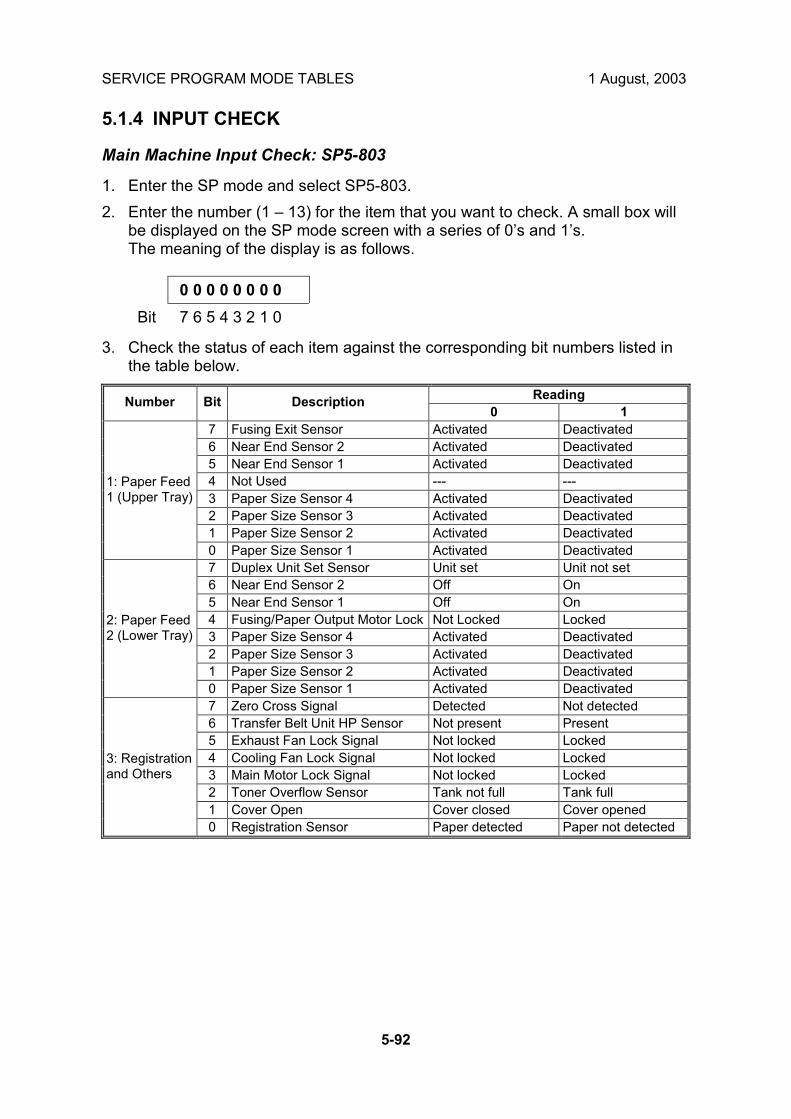
SERVICE PROGRAM MODE TABLES 1 August, 2003
5-92
5.1.4 INPUT CHECK
Main Machine Input Check: SP5-803
1. Enter the SP mode and select SP5-803. 2. Enter the number (1 � 13) for the item that you want to check. A small box will
be displayed on the SP mode screen with a series of 0�s and 1�s. The meaning of the display is as follows.
0 0 0 0 0 0 0 0 Bit 7 6 5 4 3 2 1 0
3. Check the status of each item against the corresponding bit numbers listed in the table below.
Reading Number Bit Description 0 1
7 Fusing Exit Sensor Activated Deactivated 6 Near End Sensor 2 Activated Deactivated 5 Near End Sensor 1 Activated Deactivated 4 Not Used --- --- 3 Paper Size Sensor 4 Activated Deactivated 2 Paper Size Sensor 3 Activated Deactivated 1 Paper Size Sensor 2 Activated Deactivated
1: Paper Feed 1 (Upper Tray)
0 Paper Size Sensor 1 Activated Deactivated 7 Duplex Unit Set Sensor Unit set Unit not set 6 Near End Sensor 2 Off On 5 Near End Sensor 1 Off On 4 Fusing/Paper Output Motor Lock Not Locked Locked 3 Paper Size Sensor 4 Activated Deactivated 2 Paper Size Sensor 3 Activated Deactivated 1 Paper Size Sensor 2 Activated Deactivated
2: Paper Feed 2 (Lower Tray)
0 Paper Size Sensor 1 Activated Deactivated 7 Zero Cross Signal Detected Not detected 6 Transfer Belt Unit HP Sensor Not present Present 5 Exhaust Fan Lock Signal Not locked Locked 4 Cooling Fan Lock Signal Not locked Locked 3 Main Motor Lock Signal Not locked Locked 2 Toner Overflow Sensor Tank not full Tank full 1 Cover Open Cover closed Cover opened
3: Registration and Others
0 Registration Sensor Paper detected Paper not detected

1 August, 2003 SERVICE PROGRAM MODE TABLES
5-93
Serv
ice
Tabl
es
Reading Number Bit Description
0 1 7 Duplex reverse path door Closed Open 6 Paper End Sensor Paper detected Paper not detected 5 Not used 4 Paper Size Sensor 4, By-pass Activated Deactivated 3 Paper Size Sensor 3, By-pass Activated Deactivated 2 Paper Size Sensor 2, By-pass Activated Deactivated 1 Paper Size Sensor 1, By-pass Activated Deactivated
4: By-pass Feed
0 Unit Set Signal Yes No 7 Not used Yes No 6 Unit Set Signal Connected Not connected 5 Paper Sensor Paper detected Paper not detected 4 Relay Sensor Paper detected Paper not detected 3 Exit Sensor Paper detected Paper not detected 2 Left Cover Switch Switch pressed
(cover closed) Switch not pressed
1 Middle Cover Switch Switch pressed (cover closed)
Switch not pressed
5: Relay Unit (Bridge Unit)
0 Right Cover Switch Switch pressed (cover closed)
Switch not pressed
7 Feed Motor Lock No Yes 6 F-Gate Signal Active Not active 5 Height Sensor Feed height Not feed height 4 Paper Exit Sensor Paper detected Paper not detected 3 Fusing Unit Detected Not detected 2 Total Counter Not detected Detected 1 Key Counter Detected Not detected
6: Unit Set
0 Key Card Present Detected Not detected 7 Front cover/open closed Open Closed 6 Vertical feed path Clear Not clear 5 2nd Tray Height Sensor Paper not at upper
limit Paper at upper limit
4 1st Tray Height Sensor Paper not at upper limit
Paper at upper limit
3 Lower Relay Sensor Paper detected Paper not detected 2 Upper Relay Sensor Paper detected Paper not detected 1 Lower Paper End Sensor Paper not detected Paper detected
7: Paper End
0 Upper Paper End Sensor Paper not detected Paper detected

SERVICE PROGRAM MODE TABLES 1 August, 2003
5-94
Reading Number Bit Description
0 1 7 Dip Switch - 8 On Off 6 Dip Switch - 7 On Off 5 Dip Switch - 6 On Off 4 Dip Switch - 5 On Off 3 Dip Switch - 4 On Off 2 Dip Switch - 3 On Off 1 Dip Switch - 2 On Off
8: DIP Switches
0 Dip Switch - 1 On Off 7 Not used 6 Right cover open/closed Closed Open 5 1-Bin Unit Set Detected Not detected 4 LD, HP sensor Positioned Not positioned 3 Exit Sensor (Jam) Paper detected Paper not detected 2 Entrance Sensor (Jam) Paper detected Paper not detected 1 Paper End Sensor Paper detected Paper not detected
9: Duplex Unit
0 Duplex Unit Switch Cover closed Cover open 7 Tray 4: Bit 1 8 Tray 4: Bit 0 Bit 1 Bit 0 Capacity 5 Tray 3: Bit 1 1 1 Full 4 Tray 3: Bit 0 1 0 50% or more 3 Tray 2: Bit 1 0 1 10% or more 2 Tray 2: Bit 0 0 0 Out, or tray not set 1 Tray 1: Bit 1
10: Remainder of Feed Tray 1
0 Tray 1: Bit 0 7 By-pass Yes/No 6 Not Used 5 Not Used 4 Not Used
3 Not Used Bit 2 Bit 1 Bit 0 Capacity 2 LCT: Bit 2 1 1 1 Full 1 LCT: Bit 1 1 0 0 80% or more
11: Remainder of Feed Tray 2
0 LCT: Bit 0 0 1 1 50% or more 0 1 0 30% or more 0 0 0 10% or more

1 August, 2003 SERVICE PROGRAM MODE TABLES
5-95
Serv
ice
Tabl
es
Reading Number Bit Description
0 1 7 Mailbox 9-bin Not full or no tray Full 6 Mailbox 8-bin Not full or no tray Full 5 Not used - - 4 Finisher: Shift Tray 1 Not full or no tray Full 3 Finisher: Shift Tray 2 Not full or no tray Full 2 Not used - - 1 1-Bin Exit Not full or no tray Full
12: Full Exit Tray 1
0 Machine Exit Not full or no tray Full 7 Mailbox 7-bin Not full or no tray Full 6 Mailbox 6-bin Not full or no tray Full 5 Mailbox 5-bin Not full or no tray Full 4 Mailbox 4-bin Not full or no tray Full 3 Mailbox 3-bin Not full or no tray Full 2 Mailbox 2-bin Not full or no tray Full 1 Mailbox 1-bin Not full or no tray Full
13: Full Exit Tray 2
0 Mailbox Proof Tray Not full or no tray Full
Table 1: By-pass Feed Table Paper Size Data
Number. Bit 4 Bit 3 Bit 2 Bit 1 Paper Width 1 1 1 1 Post Card 1 1 1 0 B6 SEF 1 1 0 1 B5 SEF 1 1 0 0 A5 SEF / 5.5" 1 0 1 1 B4 SEF 1 0 0 1 A4 SEF / 8.5" / 8" 0 1 1 1 A3 SEF
4: By-pass
0 0 1 1 11" x 17"

SERVICE PROGRAM MODE TABLES 1 August, 2003
5-96
ARDF Input Check: SP6-007
1. Enter the SP mode and select SP6-007. 2. Enter the number (1 � 13) for the item that you want to check. A small box will
be displayed on the SP mode screen with a series of 0�s and 1�s. The meaning of the display is as follows.
0 0 0 0 0 0 0 0 Bit 7 6 5 4 3 2 1 0
3. Check the status of each item against the corresponding bit numbers listed in the table below.
Reading Group Bit No. Description
0 1 7 Original width sensor 4 Paper not detected Paper detected 6 Original width sensor 3 Paper not detected Paper detected 5 Original width sensor 2 Paper not detected Paper detected 4 Original width sensor 1 Paper not detected Paper detected 3 Skew correction sensor Paper not detected Paper detected 2 Original set sensor Paper not detected Paper detected 1 Original B5 sensor Paper not detected Paper detected
1
0 Original LG sensor Paper not detected Paper detected 7 Original stopper HP sensor Original stopper up Original stopper
down 6 Pick-up HP sensor Cover closed Cover opened 5 Top cover Sensor Cover closed Cover opened 4 Lift sensor Pick-up roller up Pick-up roller down 3 Inverter sensor Paper not detected Paper detected 2 Exit sensor Paper not detected Paper detected 1 Registration sensor Paper not detected Paper detected
2
0 Interval Sensor Paper not detected Paper detected 3 0 Original A4 sensor

1 August, 2003 SERVICE PROGRAM MODE TABLES
5-97
Serv
ice
Tabl
es
5.1.5 OUTPUT CHECK NOTE: Motors keep turning in this mode regardless of upper or lower limit sensor
signals. To prevent mechanical or electrical damage, do not keep an electrical component on for a long time.
Main Machine Output Check: SP5-804
1. Open SP mode 5-804. 2. Select the SP number that corresponds to the component you wish to check.
(Refer to the table on the next page.) 3. Press On then press Off to test the selected item.
NOTE: You cannot exit and close this display until you press off to switch off the output check currently executing. Do not keep an electrical component switched on for a long time.
B135S902.WMF

SERVICE PROGRAM MODE TABLES 1 August, 2003
5-98
SP5-804 Output Check Table No. Description No. Description 1 1st Paper Feed CL 45 Duplex Junction Gate Solenoid () 2 2nd Paper Feed CL 3 3rd Paper Feed CL (PTU) 47 Relay Junction Gate Solenoid 4 4th Paper Feed CL (PTU) 5 By-pass Paper Feed CL 50 Tray Junction Gate Solenoid 6 LCT Paper Feed CL 51 Stapler Junction Gate Solenoid 52 Positioning Roller Solenoid (Finishers)
13 By-pass Pick-up Solenoid 14 LCT Pick-up Solenoid 56 Toner Bottle Motor 57 Transfer Belt Positioning Clutch
17 Transport Motor 1 (Finisher) 18 Transport Motor 2 (Finisher) 62 Quenching Lamp 19 Exit Motor (Finisher) 63 Charge Bias 20 Staple Motor (Finisher) 21 Punch Motor (Finisher) 67 Development Bias
25 LCT Motor 69 Transfer Belt Voltage 26 Bank Motor (Paper Tray Unit) 70 ID Sensor LED 27 Fusing/Feed-Out Motor 28 Main Motor 75 Exhaust Fan 29 Duplex Transport Motor 76 Elec. Equipment Cooling Fan (High Rev.) 30 Duplex Inverter Motor � Rev. 31 Duplex Inverter Motor � Fwd 78 Relay Fan Motor 32 Feed/Development Motor 79 Fusing Fan Motor 85 Total Counter
35 Bank Relay Clutch (Paper Tray Unit)
36 Relay Clutch
38 LCT Relay Clutch 92 Shift Tray Lift Motor (Finisher) 39 Registration Clutch 93 Jogger Motor (Finisher) 40 Not used 94 Stapler Unit Motor (Finisher) 41 Exit Junction Gate Solenoid
(Upper Unit) 95 Stack Feed Out Motor (Finisher)
42 Duplex Junction Gate Solenoid (Lower Unit)
96 Shift Motor (Finisher)
97 Stapler Rotation Motor (Two-Tray Finisher)

1 August, 2003 SERVICE PROGRAM MODE TABLES
5-99
Serv
ice
Tabl
es
ARDF Output Check: SP6-008)
1. Open SP mode SP6-008. 2. Select the SP number that corresponds to the component you wish to check.
(Refer to the table below.) 3. Press On then press Off to test the selected item. You cannot exit and close
this display until you click Off to switch off the output check currently executing.
No. Description 1 Feed Motor (Forward) 2 Feed Motor (Reverse) 3 Drive Motor (Forward) 4 Inverter Motor (Forward) 5 Inverter Motor (Reverse) 6 Feed Clutch 7 Inverter Solenoid 8 Pick-up Motor (Forward) 9 Pick-up Motor (Reverse)
5.1.6 SMC PRINT OUT LISTS: SP5-990
1. Open SP mode 5-990 and select the number corresponding to the list that you wish to print.
SMC (System Parameter and Data Lists) 1 All Data List 2 SP Mode Data List 3 UP Mode Data List 4 Logging Data List 5 Self-Diagnostics Results List 6 Non-Default 7 NIB Summary 8 NetFile Application Log 21 Copy UP Mode List 22 Scanner SP Mode List 23 Scanner UP Mode List
2. Press �Execute� on the touch panel. 3. Select �Single Face� or �Both Face�. 4. After printing the list, press �Close� to return to the SP mode display. 5. Press Exit twice to close the SP Mode screen and return to copy mode.

SERVICE PROGRAM MODE TABLES 1 August, 2003
5-100
5.1.7 MEMORY CLEAR: SP5-801
Executing Memory All Clear resets all the settings stored in the NVRAM to their default settings except the following:
SP7-003-1: Electrical total counter value SP5-811-1: Machine serial number SP5-907: Plug & Play Brand Name and Production Name Setting
1. Execute SP5-990 to print out all SMC Data Lists. 2. Open SP mode 5-801. 3. Press the number for the item that you want to initialize. The number you select
determines which application is initialized. For example, press 1 if you want to initialize all modules or select the appropriate number from the table below.
5801 Memory Clear Comments 5801 1 All Clear Initializes items 2 ~ 12 below. *1 5801 2 Engine Initializes all registration settings for the engine and
processing settings. *1 5801 3 SCS Initializes default system settings, CSS settings,
operation display coordinates, and ROM update information. *1
5801 4 IMH Memory Clr Initializes the registration setting for the image memory handler by deleting all image files on the HDD.
5801 5 MCS Initializes the automatic delete time setting for stored documents.
5801 6 Copier application
Initializes all copier application settings.
5801 7 Fax application Initializes the fax reset time, job login ID, all TX/RX settings, local storage file numbers, and off-hook timer.
5801 8 Printer application
Initializes the printer defaults, programs registered, the printer SP Bit SW, and printer CSS counter.
5801 9 Scanner application
Initializes the scanner defaults for the scanner and all the Scanner SP modes.
5801 10 Web Service/Network Application
Deletes the NFA management files and thumbnails, and initializes the JOB login ID.
5801 11 NCS Initializes the system defaults and interface settings (IP addresses also), the SmartNetMonitor for Admin, WebStatusMonitor settings, and the TELNET settings.
5801 12 R-FAX Initializes the Job login ID, SmartNetMonitor for Admin, Job History, and local storage file numbers.
5801 13 Clear DCS Settings
Initialization
5801 14 Clear UCS Settings
Initialization
1*: Resetting 1~3 resets the operation panel screen coordinates, so after executing 1, 2, or 3, you must re-calibrate the screen.

1 August, 2003 SERVICE PROGRAM MODE TABLES
5-101
Serv
ice
Tabl
es
4. Press Execute, and then follow the prompts on the display to complete the procedure.
5. Make sure that you perform the following settings: • Do the laser beam pitch adjustment (SP2-109). • Do the printer and scanner registration and magnification adjustments (☛
3.21 Replacement and Adjustment, �Copy Adjustments� in the B003/B004 Service Manual).
• Do the touch screen calibration (☛ 3.21.4 Replacement and Adjustment, �touch screen calibration� in the B003/B004 Service Manual).
• Referring to the SMC data lists, re-enter any values, which had been changed from their factory settings.
• Do SP 3-001-2 (ID Sensor Initial Setting). 6. Check the copy quality and the paper path, and do any necessary adjustments.

DIP SWITCHES 1 August, 2003
5-102
5.2 DIP SWITCHES Controller: DIP SW2
DIP SW No. ON OFF 1 IC Card Boot System ROM Boot 2 3 4
Keep at �OFF�
I/O Board: DIP SW101
DIP SW No. Function ON OFF 1 Copy Speed 35 cpm (180 mm/s) 45 cpm (230 mm/s) 2 Jam Detection
(see Note) Off On
3 Engine Program Recovery
On Off
4 Print Output for Debugging
OFF (Do not change)
5 Factory Duplex Function Check
OFF (Do not change)
JPN NA EUR China Taiwan Asia Korea 6 OFF ON OFF OFF ON ON OFF 7 OFF OFF ON OFF OFF ON ON 8
Destination
OFF OFF OFF ON ON OFF ON
NOTE: Disabling jam detection is effective only for the main machine (not for the options).

1 August, 2003 USING THE DEBUG LOG
5-103
Serv
ice
Tabl
es
5.3 USING THE DEBUG LOG This machine provides a Save Debug Log feature that allows the Customer Engineer to save and retrieve error information for analysis. Every time an error occurs, debug information is recorded in volatile memory but this information is lost when the machine is switched off and on. The Save Debug Log feature provides two main features: • Switching on the debug feature so error information is saved directly to the HDD
for later retrieval. • Copying the error information from the HDD to an IC card. When a user is experiencing problems with the machine, follow the procedure below to set up the machine so the error information is saved automatically to the HDD. 5.3.1 SWITCHING ON AND SETTING UP SAVE DEBUG LOG
The debug information cannot be saved the until the �Save Debug Log� function has been switched on and a target has been selected.
1. Enter the SP mode. • Press ( (Clear Modes) then use the 10-key pad to enter #)*. • Press and hold down $ (Clear/Stop) for more than 3 seconds. • Press �Copy SP� on the touch-panel. • Enter +,+* then press ".
2. Under �5857 Save Debug Log�, press #. COPY : SP-5857-001 Save Debug Log On/Off (1:ON 0:OFF)
_1_ Initial 0
3. On the control panel keypad, press �1� then press ". This switches the Save Debug Log feature on. NOTE: The default setting is �0� (OFF). This feature must be switched on in
order for the debug information to be saved.

USING THE DEBUG LOG 1 August, 2003
5-104
4. Next, select the target destination where the debug information will be saved. Under �5857 Save Debug Log�, touch �2 Target�, enter �2� with the operation panel key to select the hard disk as the target destination, then press ". COPY : SP-5-857-002 Save Debug Log Target (2:HDD 3:IC Card)
_2_ Initial 2
NOTE: Select �3 IC Card� to save the debug information directly to the IC card if it is inserted in the service slot.
5. Now touch �5858� and specify the events that you want to record in the debug log. SP5858 (Debug Save When) provides the following items for selection.
1 Engine SC Error Saves data when an engine-related SC code is generated.
2 Controller SC Error Saves debug data when a controller-related SC Code is generated.
3 Any SC Error Saves data only for the SC code that you specify by entering code number.
4 Jam Saves data for jams.
NOTE: More than one event can be selected. Example 1: To Select Items 1, 2, 4 Touch the appropriate items(s). Press �ON� for each selection. This example shows �Engine SC Error� selected. COPY : SP-5-858-001 Debug Save When Engine SC Error __OFF__ __ON__ Example 2: To Specify an SC Code Touch �3 Any SC Error�, enter the 3-digit SC code number with the control panel number keys, then press ". This example shows an entry for SC670. COPY : SP-5-858-001 Debug Save When Any SC Error __670
NOTE: For details about SC code numbers, please refer to the SC tables in Section �4. Troubleshooting�.

1 August, 2003 USING THE DEBUG LOG
5-105
Serv
ice
Tabl
es
6. Next, select the one or more memory modules for reading and recording debug information. Touch �5859�. Under �5859� press the appropriate key item for the module that you want to record. Enter the appropriate 4-digit number, then press ". NOTE: Refer to the two tables below for the 4-digit numbers to enter for each
key. The example below shows �Key 1� with �2222� entered. COPY : SP-5-859-001 Debug Save Key No. Key 1
___2222 The following keys can be set with the corresponding numbers. (The initials in parentheses indicate the names of the modules.)
4-Digit Entries for Keys 1 to 10 KEY NO. COPY PRINTER SCANNER WEB
1 2222 (SCS) 2 2223 (SRM) 3 256 (IMH) 4 1000 (ECS) 5 1025 (MCS) 6 4848 (COPY) 4400 (GPS) 5375 (Scan) 5682 (NFA) 7 2224 (BCU) 4500 (PDL) 5682 (NFA) 6600 (WebDB) 8 4600 (GPS-PM) 3000 (NCS) 3300 (PTS) 9 2000 (NCS) 2000 (NCS) 6666 (WebSys) 10 2224 (BCU) 2000 (NCS)
NOTE: The default settings for Keys 1 to 10 are all zero (�0�). Key to Acronyms
Acronym Meaning Acronym Meaning ECS Engine Control Service NFA Net File Application GPS GW Print Service PDL Printer Design Language GSP-PM GW Print Service � Print Module PTS Print Server IMH Image Memory Handler SCS System Control Service MCS Memory Control Service SRM System Resource
Management NCS Network Control Service WebDB Web Document Box
(Document Server)
The machine is now set to record the debugging information automatically on the HDD (the target selected with SP5-857-002) for the events that you selected SP5-858 and the memory modules selected with SP5-859.

USING THE DEBUG LOG 1 August, 2003
5-106
Please keep the following important points in mind when you are doing this setting: • Note that the number entries for Keys 1 to 5 are the same for the Copy, Printer,
Scanner, and Web memory modules. • The initial settings are all zero. • These settings remain in effect until you change them. Be sure to check all the
settings, especially the settings for Keys 6 to 10. To switch off a key setting, enter a zero for that key.
• You can select any number of keys from 1 to 10 (or all) by entering the corresponding 4-digit numbers from the table.
• You cannot mix settings for the groups (COPY, PRINTER, etc.) for 006~010. For example, if you want to create a PRINTER debug log you must select the settings from the 9 available selections for the �PRINTER� column only.
• One area of the disk is reserved to store the debug log. The size of this area is limited to 4 MB.

1 August, 2003 USING THE DEBUG LOG
5-107
Serv
ice
Tabl
es
5.3.2 RETRIEVING THE DEBUG LOG FROM THE HDD
1. Insert the IC card into the copier. 2. Enter the SP mode and execute SP5857 007 (Copy HDD to IC Card (Latest 4
MB) to write the debugging data to the IC card. NOTE: The IC card can hold up to 4MB of data. If the debugging data is larger
than 4MB, you can switch to another IC card. 3. After you return to the service center, use a card reader to copy the file and
send it for analysis to Ricoh by email, or just send the IC card by mail. 5.3.3 RECORDING ERRORS MANUALLY
Since only SC errors and jams are recorded to the debug log automatically, for any other errors that occur while the customer engineer is not on site, please instruct customers to perform the following immediately after occurrence to save the debug data. Such problems would include a controller or panel freeze. NOTE: In order to use this feature, the customer engineer must have previously
switched on the Save Debug Feature (SP5857-001) and selected the hard disk as the save destination (SP5857-002).
1. When the error occurs, on the operation panel, press- (Clear Modes).
2. On the control panel, enter �01� then hold down . for at least 3 sec. until the machine beeps then release. This saves the debug log to the hard disk for later retrieval with an IC card by the service representatives.
3. Switch the machine off and on to resume operation.
The debug information for the error is saved on the hard disk so the service representatives can retrieve it on their next visit by copying it from the HDD to an IC card.

1 August, 2003 BOARD STRUCTURE
6-1
Det
aile
dD
escr
iptio
ns
6. DETAILED SECTIOIN DESCRIPTIONS Here is a summary of some of the new features described in this section. The section numbers preceded with the ☛ mark refer to the section number of this document where the new or amended feature is described. • The physical location of the IOB has changed, making it much easier to remove.
(☛6.1.1) • There is no PFB in this machine. The function of the PFB has been built into the
IOB. (☛6.1.1) • The layout of the controller board has been modified. ( ☛6.1.2) • Image processing for the B135 (35 cpm)/ B138 (45 cpm) has been revised.
(☛6.2) • A new cleaning blade has been added to the PCU in order to provide better
cleaning of the OPC drum. (☛6.3.1, 6.3.2) • The voltage adjustment for thicker paper, OHP sheets, etc. fed from the bypass
tray has changed. (☛6.4.1, 6.4.2) • Two new dust blades have been added for the registration roller and the
registration idle roller. (☛6.5.1 • The cleaning roller inside the fusing unit has been re-designed to dissipate heat
more efficiently (☛6.6.1) • The new hot roller strippers are narrower and a new feature jogs the fusing/paper
exit motor at prescribed intervals in order to dislodge toner and paper dust collected on the hot roller strippers. (☛6.6.2)
• The line speed of the B138 (45 cpm) machine is adjusted down automatically to 35 cpm in order to print on thick paper. This adjustment was not provided in the previous models. (☛6.6.4
• Two new cooling fans have been added to the fusing unit to further ensure that the fusing unit runs cooler for the new toner which has a much lower melting temperature.( ☛6.6.5)
• To reduce the incidence of toner scanner, the sponge strip has been replaced with a velvet strip that extends across the length of the fusing unit, new triangular seals are attached to each corner of the fusing unit. (☛6.6.6)
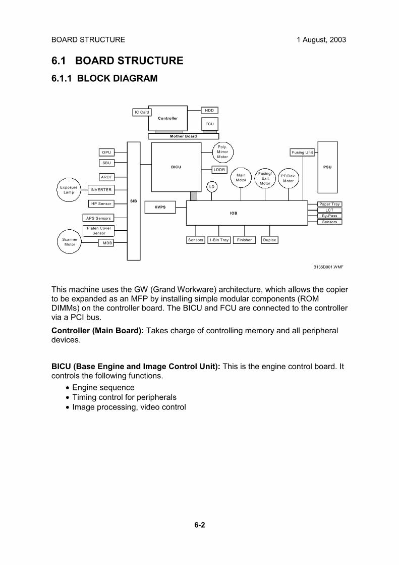
BOARD STRUCTURE 1 August, 2003
6-2
6.1 BOARD STRUCTURE 6.1.1 BLOCK DIAGRAM
This machine uses the GW (Grand Workware) architecture, which allows the copier to be expanded as an MFP by installing simple modular components (ROM DIMMs) on the controller board. The BICU and FCU are connected to the controller via a PCI bus. Controller (Main Board): Takes charge of controlling memory and all peripheral devices. BICU (Base Engine and Image Control Unit): This is the engine control board. It controls the following functions.
• Engine sequence • Timing control for peripherals • Image processing, video control
HDD
BICU
OPU
SBU
ARDF
ExposureLamp
INVERTER
HP Sensor
APS Sensors
MDBSensors
HVPS
ScannerMotor
IOB
Platen CoverSensor
1-Bin Tray Finisher Duplex
LD
LDDR
SIB
ControllerIC Card
Mother Board
FCU
Poly.MirrorMotor
Paper TrayLCT
By-PassSensors
Fusing Unit
PSU
MainMotor
Fusing/Exit
Motor
PF/Dev.Motor
B135D901.WMF

1 August, 2003 BOARD STRUCTURE
6-3
Det
aile
dD
escr
iptio
ns
IOB: The IOB (Input/Output Board) handles the following functions: • Drive control for the sensors, motors, and solenoids of the main unit • PWM control for the high voltage supply board • Serial interface with peripherals • Fusing control
NOTE: The IOB is now located directly behind the rear covers for easier access. The machine no longer contains the PFB (Paper Function Board). The functions of the PFB (paper feed control) have been taken over by the IOB. The same IOB is used for both the B135 and B138 but the DIP switches must be set correctly for each. See Section �3 Replacement and Adjustment� for details.
SIB (Scanner Interface Board): Controls the scanner, and serves as the signal I/F board for the SBU and the OPU. The SIB passes signals between the BICU and the scanner unit components, and transmits video signals from the SBU to the BICU. OPU (Operation Panel Unit): Controls operation panel and display. SBU (Sensor Board Unit): Receives analog signals from the CCD and converts them into digital signals. LDDR (Laser Diode Driver): The LD driver circuit board. MDB (Motor Drive Board): Controls the scanner motor. Mother Board: This board interfaces the controller and the BICU and FCU. FCU (Facsimile Control Unit): Controls fax communications and fax features.

BOARD STRUCTURE 1 August, 2003
6-4
6.1.2 CONTROLLER
IC CARD
CPU
ASIC: MARIMBA
ResidentSDRAM (64MB)
SDRAM DIMM 128MB
XTL
ClockGenerator
NIB
IEEE1284(Centronics I/F)
Engine I/F (PCI)MB
HDD(More than 20
GB)
DC Conv.3V→5V
IEEE 1394USB 2.0
IEEE 802.11bBluetooth
(Only One)
NVRAM + RTC32kB
NVRAM 32kB
CPU I/F (120MHz)MEMORY I/F
(120MHz)
DC Conv.(3V→5V)
ResidentFlash ROM (12MB)
(System/NIB Firmware)
ROM_DIMM(Printer + Scanner)
ROM_DIMM (PS3)
(Option)
(Option)
(Options)
(Option)
BICU
FCU
(Option)
(Option)
(Option)
B135D902.WMF

1 August, 2003 BOARD STRUCTURE
6-5
Det
aile
dD
escr
iptio
ns
The controller controls all applications, including copier, printer, scanner, and fax applications. To add the optional printer, scanner, or fax applications, ROM DIMMs must be installed on the controller. The fax option, however, also requires FCU and NCU installation. NOTE: The controller boards are machine specific and are not interchangeable.
The controller board for the B135 (35 cpm) must be installed in the B135 and controller board for the B138 (45 cpm) must be installed in the B138.
The following firmware and application software can be downloaded from the Controller IC Card slot. • Controller (System OS) • Operation panel • BICU (engine control) • Printer • Scanner • Fax • PostScript 3 • NIB • FCU CPU: Employs RM7065. Clock frequency: 300 MHz. ASIC: Uses a dedicated chip developed for use with GW architecture. The CPU and memory I/F employ a 120 MHz bus (32 bit). These components perform CPU and I/F control and also control all of the following functions: memory, local bus, interrupts, PCI bus, video data, HDD, network, operation panel, IEEE1284, and image processing. SDRAM: Comprises a 64 MB RAM chip, expandable with a 128 MB SDRAM. System Flash ROM: Provided with an 12 MB Flash ROM for the system and NIB firmware. Flash ROM DIMM Slots: Two slots are provided for two ROM DIMMs (8 MB or 16 MB). Expansion slots provided for the optional printer/scanner, and PostScript 3 applications. NVRAM: 32 KB of NVRAM are provided for the system. NVRAM stores many settings, including OS system log information, copier calendar, current system settings, user accounts (max. 100) and all settings for the fax, printer, scanner, and network. The NVRAM also has the RTC (Real Time Clock) for time management.
NOTE: Optional NVRAM, which can store to 400 user accounts, can be installed on the controller.

BOARD STRUCTURE 1 August, 2003
6-6
HDD: A 3.5" HDD (more than 20 GB) can be connected using an IDE I/F. The hard disk is partitioned as shown below.
Partition Size Function Power OFF Comment
File System 1 500 MB Downloaded fonts, forms. Remains
File System 2 500 MB Job spooling area. Erased
File System 3 2000 MB Work data area Remains Used for document server application.
Image TMP 5200 MB Collation, sample print, protected print.
Erased
Image LS*1 7800 MB Document server, local storage archive
Remains
Storage capacity (Max. *2): 2500 pp. (Copy) 9000 pp. (Print/ Fax/ Scanner)
Image Area Management 100MB Stores image
area information Remains
Job Log 20 MB Job log. Remains Others 3362 MB Total 20 GB Remains
*1: When an application uses an image page, first it uses the Image LS area. If this area is in use and not available, then it uses the Image TMP area.
*2: These areas are used for applications to store copy, print, fax, and scanned pages. The actual number of pages that can be stored differs depending on the content of the document and the scanning resolution.

1 August, 2003 IMAGE PROCESSING
6-7
Det
aile
dD
escr
iptio
ns
6.2 IMAGE PROCESSING
6.2.1 OVERVIEW
SBU: The SBU (Sensor Board Unit) converts the analog signal from the CCD to an 8-bit digital signal and sends it to the SIB. SIB: Relays image signals and controls the scanner. BICU: The BICU (Base Engine Image Control Unit) performs timing control and command control. The IPU on the BICU processes auto shading, filtering, magnification, γ correction, and gradation. The memory controller performs image compression, decompression, and memory address control (for binary picture processing mode only) LD Unit: Performs dual channel multi-beam exposure, multiple exposure, and synchronous detection. Controller: Performs dual channel multi-beam exposure, multiple exposure, and synchronous detection.
SIB
IPUDrum
BICULDDR
Controller
SBU
CC
D
HDD
FCI
LDController
(GAVD)LDDriver
SIB
Mother Board
B135D903.WMF
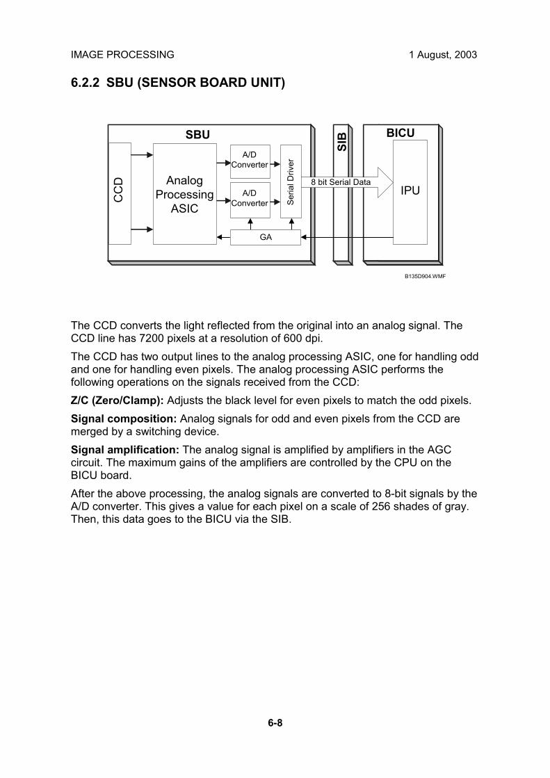
IMAGE PROCESSING 1 August, 2003
6-8
6.2.2 SBU (SENSOR BOARD UNIT)
The CCD converts the light reflected from the original into an analog signal. The CCD line has 7200 pixels at a resolution of 600 dpi. The CCD has two output lines to the analog processing ASIC, one for handling odd and one for handling even pixels. The analog processing ASIC performs the following operations on the signals received from the CCD: Z/C (Zero/Clamp): Adjusts the black level for even pixels to match the odd pixels. Signal composition: Analog signals for odd and even pixels from the CCD are merged by a switching device. Signal amplification: The analog signal is amplified by amplifiers in the AGC circuit. The maximum gains of the amplifiers are controlled by the CPU on the BICU board. After the above processing, the analog signals are converted to 8-bit signals by the A/D converter. This gives a value for each pixel on a scale of 256 shades of gray. Then, this data goes to the BICU via the SIB.
IPU
SBUC
CD
BICU
SIB
AnalogProcessing
ASIC
A/DConverter
A/DConverter
GA
Seria
l Driv
er
8 bit Serial Data
B135D904.WMF

1 August, 2003 IMAGE PROCESSING
6-9
Det
aile
dD
escr
iptio
ns
6.2.3 AUTO IMAGE DENSITY (ADS)
This mode prevents the background of an original from appearing on copies. The copier scans the auto image density detection area [A]. This corresponds to a narrow strip at one end of the main scan line, as shown in the diagram. As the scanner scans down the page, the IPU on the BICU detects the peak white level for each scan line, within this narrow strip only. From this peak white level, the IPU determines the reference value for A/D conversion for the scan line. Then, the IPU sends the reference value to the A/D controller on the SBU. When an original with a gray background is scanned, the density of the gray area is the peak white level density. Therefore, the original background will not appear on copies. Because peak level data is taken for each scan line, ADS corrects for any changes in background density down the page. As with previous digital copiers, the user can select manual image density when selecting auto image density mode and the machine will use both settings when processing the original.
75mm15mm
0.5mm
Sub scan direction
B135D905.WMF
[A]
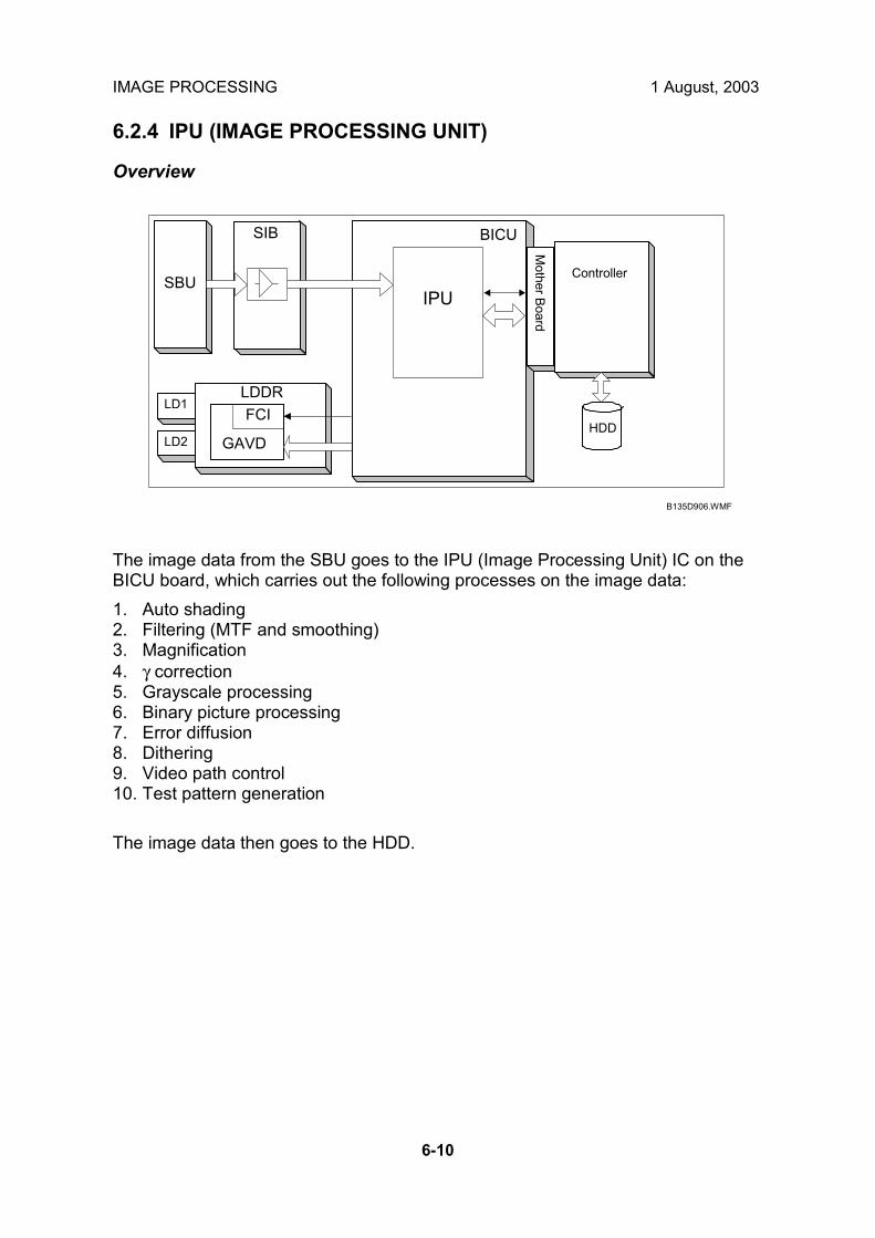
IMAGE PROCESSING 1 August, 2003
6-10
6.2.4 IPU (IMAGE PROCESSING UNIT)
Overview
The image data from the SBU goes to the IPU (Image Processing Unit) IC on the BICU board, which carries out the following processes on the image data: 1. Auto shading 2. Filtering (MTF and smoothing) 3. Magnification 4. γ correction 5. Grayscale processing 6. Binary picture processing 7. Error diffusion 8. Dithering 9. Video path control 10. Test pattern generation The image data then goes to the HDD.
HDD
LD1
LD2
ControllerSBU
SIB
LDDR
Mother Board
GAVD
FCI
IPU
BICU
B135D906.WMF

1 August, 2003 IMAGE PROCESSING
6-11
Det
aile
dD
escr
iptio
ns
6.2.5 IMAGE PROCESSING MODES
The user can select one of the following modes with the User Tools screen: Text, Text/Photo, Photo, Pale, Generation. Each of these modes has a range of different settings (e.g. Soft, Normal, Sharp, etc). For each mode, a Custom Setting options is also available. This Custom Setting holds the values selected with the SP modes, which can be adjusted to meet special requirements that cannot be covered by the standard settings. To display this screen, press User Tools/Counter> Copier/Document Server Settings> General Features> Copy Quality.
Mode Function
Text Best reproduction of text and sharp lines. Ignores background texture. (☛ pg. 6-14)
Text/Photo Good reproduction of mixed text and photographs with accurate grayscaling, better than that achieved in the Text mode. (☛ pg. 6-15)
Photo Best possible reproduction of photographs. (☛ pg.6-16)
Pale Reproduction similar to Text mode, but of lower contrast. Ideal for copying thin originals. (☛ pg.6-17)
Generation Copy Attempts to achieve the best reproduction of copied originals, which have faded due to making copies of copies. (☛ pg.6-18)
B135D907.WMF

IMAGE PROCESSING 1 August, 2003
6-12
General Image Processing Flow Signals from SBU Processing conducted as required.
!
Shading Correction
!!!!
Pre- Filter Background Erase
!!!!
Pre-Filter Smoothing
!!!!
Main Scan Magnification
!!!! (Text/Photo, Photo) Primary Compression, Decompression
Controller
Independent Dot Erase HDD
!!!!
Filtering
!!!! (Text, Pale, Generation)
Secondary Compression, Decompression
γγγγ Coefficient Sent to HDD
!!!! Video Control Scanner/Printer Application
Grayscale Processing FCU
!!!! FAX Application
LD Unit

1 August, 2003 IMAGE PROCESSING
6-13
Det
aile
dD
escr
iptio
ns
6.2.6 SUMMARY OF IMAGE PROCESSING FUNCTIONS
Shading correction: Compensates for the possible differences in the amount of light at the edges and center of a scanned image caused by the scanner lens, or scatter among pixels of the CCD. Pre-Filter Background erase: Attempts to eliminate the heavy background texture from copies (newspaper print or documents printed on coarse paper). Elements below the selected threshold level are eliminated. Pre-Filter Smoothing: Reproduces halftones while reducing the incidence of moiré which can occur as a result of compressing and then decompressing the image. Main scan magnification: Adjusts magnification to the desired level by processing adjusting multiple, adjacent pixels in the direction of main scanning. Adjustment of magnification in the sub scan direction is done by changing the scanning speed. Independent dot erase: Attempts to recognize and eliminate scattered, independent dots in copies. Processes only pixels of high density and eliminates those of low density. Filtering (MTF filter/smoothing): Performs mainly edge enhancement with the MTF filter. Performs smoothing only in the Photo mode. The matrix size of the filter is 9 pixels x 7 lines.
Gamma (γγγγ) coefficient: Controls the image density for images processed with grayscaling. Copy density adjustment is achieved with special notch γ coefficient conversion. The best γ coefficient suited for the selected mode can be stored and adjusted as needed. Grayscale processing: Performs reproduction of grayscales, using mainly error diffusion. (In the Photo mode, conducts processing with dithering.)

IMAGE PROCESSING 1 August, 2003
6-14
6.2.7 IMAGE PROCESSING STEPS AND RELATED SP MODES
Text Mode The Text mode achieves quality reproduction of text and sharp lines and ignores background texture. Processing is conducted with a high resolution MTF filter; special processing with the γ coefficient prevents background reproduction and achieves the best reproduction of images with error diffusion. Because the Soft and Normal settings use a weak MTF filter, the quality of the image is improved with the elimination of moiré. The Sharp selection uses an MTF filter stronger than that of the Normal setting, thus increasing the sharpness of lines. Image Processing Flow Related SP Modes
Scanner Image Correction
Shading Correction
!
Pre-Filter Processing Background Erase SP4903 65 (Background Erase Level: Text Mode)
!
Pre-Filter Smoothing SP4903 10 (Pre-Filter: Text)
!
Magnification Main Scan Direction SP2909 1 (Main Scan Magnification)
!
Independent Dot Erase SP4903 60 (Independent Dot Erase: Text Mode)
!
Filter Processing MTF Correction SP4904 20~23 Text (General Quality) (☛6.2.12)
!
Density Control γ Coefficient
!
Grayscale Processing
Error Diffusion
NOTE: An SP code number and name set in bold italic denotes an SSP (Special Service Program) mode. To access an SSP, enter the SP mode: press and hold down ! on the 10-key pad then �Copy SP� on the touch-screen.

1 August, 2003 IMAGE PROCESSING
6-15
Det
aile
dD
escr
iptio
ns
Text/Photo Mode Text/Photo mode achieves high quality reproduction of pictures with accurate grayscaling. Processing is conducted with the special γ coefficient which reproduces a wide range of grayscale. Compared with the Text mode, text reproduced in the Text/Photo mode appears lighter and textured backgrounds could appear on copies, but the incidence of moiré is reduced with and edge detection filter. Because Photo Priority uses an MTF filter weaker than that of the Normal setting, the quality of the image is improved with the elimination of moiré. The Text Priority selection uses an MTF filter stronger than that of the Normal setting, thus increasing the sharpness of lines. Image Processing Flow Related SP Modes
Scanner Image Correction
Shading Correction
!
Pre-Filter Processing Background Erase SP4903 67 (Background Erase Level:
Text/Photo Mode)
!
Pre-Filter Smoothing SP4903 13 (Pre-Filter: Text/Photo)
!
Magnification Main Scan Direction SP2909 1 (Main Scan Magnification)
!
Independent Dot Erase SP4903 62 (Independent Dot Erase Level)
!
Filter Processing MTF Correction SP4904 25~28 Text/Photo (General) Quality (☛�Text Photo Mode�, pg.6-25)
!
Density Control γ Coefficient
!
Grayscale Processing
Error Diffusion
NOTE: An SP code number and name set in bold italic denotes an SSP (Special
Service Program) mode. To access an SSP, enter the SP mode: press and hold down ! on the 10-key pad then �Copy SP� on the touch-screen.

IMAGE PROCESSING 1 August, 2003
6-16
Photo Mode Photo mode emphasizes grayscale processing to achieve the best possible reproduction of photographs and eliminate moiré by using the highest density and γ coefficient in the reproduction of grayscales and dithering. Print Photo performs smoothing and dithering for photos copied from magazines, newspapers, etc. The Normal selection uses a higher resolution setting and employs error diffusion but does not use smoothing to improve the appearance of text in photographs. Glossy photo paper employs MTF filter processing and error diffusion to copy glossy or matte photographs and achieves a low incidence of moiré, thus reproducing copies of photographs of high resolution. For photo mode, the features used depend on which type of greyscale processing has been selected for Photo mode (either �dithering and smoothing� or �error diffusion and MTF�); this depends on the setting of SP 4904 001. Details are explained later in this section. Image Processing Flow Related SP Modes
Scanner Image Correction
Shading Correction
!
Pre-Filter Processing Background Erase SP4903 66 (Background Erase Level: Photo
Mode)
!
Pre-Filter Smoothing SP4903 12 (Pre-Filter: Photo Mode)
!
Magnification Main Scan Direction SP2909 1 (Main Scan Magnification)
!
Filter Processing
Smoothing/MTF Correction
SP4904 024 Photo (General Quality) (☛pg. 6-24)
!
Density Control γ Coefficient
!
Grayscale Processing
Dither/Error Diffusion SP4904 2 (Quality Photo Mode)
NOTE: An SP code number and name set in bold italic denotes an SSP (Special
Service Program) mode. To access an SSP, enter the SP mode: press and hold down ! on the 10-key pad then �Copy SP� on the touch-screen.

1 August, 2003 IMAGE PROCESSING
6-17
Det
aile
dD
escr
iptio
ns
Pale (Low-Density Mode) Pale achieves image quality comparable with Text mode, but of lower contrast. Pale employs an MTF filter stronger than that employed by the Text mode and uses a darker γ coefficient, thus increasing the incidence of copying textured backgrounds. Ideal for copying extremely thin originals. Soft employs an MTF filter weaker than Normal, thus achieving a softer image with less moiré. Sharp employs an MTF filter stronger than that of Normal, thus increasing the sharpness of lines. Image Processing Flow Related SP Modes
Scanner Image Correction Shading Correction
!
Pre-Filter Processing Background Erase SP4903 68 (Background Erase Level: Light
Original)
!
Pre-Filter Smoothing SP4903 15 (Pre-Filter: Light)
!
Magnification Main Scan Direction SP2909 1 (Main Scan Magnification)
!
Independent Dot Erase SP4903 63 (Independent Dot Erase: Light Original)
!
Filter Processing MTF Correction SP4904 29 Pale (General) Quality (☛pg. 6-26)
!
Density Control γ Coefficient
!
Grayscale Processing Error Diffusion
NOTE: An SP code number and name set in bold italic denotes an SSP (Special
Service Program) mode. To access an SSP, enter the SP mode: press and hold down ! on the 10-key pad then �Copy SP� on the touch-screen.

IMAGE PROCESSING 1 August, 2003
6-18
Generation Copy Mode Generation Copy, based mainly on Text mode, aims to achieve the best reproduction of copied originals (so called �generation copies� or copies of copies). This mode 1) employs an MTF filter weaker than that of the Text mode to eliminate spurious dots, 2) uses the γ coefficient to smooth the image, and 3) uses generation processing to thicken thin lines. Soft employs an MTF filter weaker than the Normal setting to achieve a softer image with less moiré. Sharp employs an MTF filter stronger than that for Normal to emphasize lines for better image quality. Image Processing Flow Related SP Modes
Scanner Image Correction Shading Correction
!
Pre-Filter Processing Background Erase SP44903 69 (Background Erase Level:
Generation Copy)
!
Pre-Filter Smoothing SP4903 16 (Pre-Filter: Generation Copy)
!
Magnification Main Scan Direction SP2909 1 (Main Scan Magnification)
!
Independent Dot Erase SP4903 64 (Independent Dot Erase: Generation Copy)
!
Generation Mode SP4903 75 ~ 77 (Line Width Correction: Generation Copy)
Filter Processing MTF Correction SP4904 30 Generation (General) Quality
(☛pg. 6-26)
!
Density Control γ Coefficient
!
Grayscale Processing Error Diffusion
NOTE: An SP code number and name set in bold italic denotes an SSP (Special
Service Program) mode. To access an SSP, enter the SP mode: press and hold down ! on the 10-key pad then �Copy SP� on the touch-screen.

1 August, 2003 IMAGE PROCESSING
6-19
Det
aile
dD
escr
iptio
ns
6.2.8 PRE-FILTERING
SP mode settings 4903 10 ~ 15 select pre-filters by changing the filter coefficient settings.
Original Mode SP No. Default Setting Mag. Smoothing
Text SP4903 10 0 0 25% ~ 400% OFF Photo SP4903 12 0 1 25% ~ 50% Weak Text/Photo SP4903 13 0 2 25% ~ 50% Medium Pale SP4903 15 0 3 25% ~ 50% Strong Generation SP4903 16 0 4 25% ~ 99% Weak ↓↓↓↓ 5 25% ~ 99% Medium Range 0 ~ 9 6 25% ~ 99% Strong 7 25% ~ 400% Weak 8 25% ~ 400% Medium 9 25% ~ 400% Strong
NOTE: An SP code number and name set in bold italic denotes an SSP (Special
Service Program) mode. To access an SSP, enter the SP mode: press and hold down ! on the 10-key pad then �Copy SP� on the touch-screen.
These SP mode settings are provided to reduce the incidence of moiré in the reproduction of images whose data signals have been compressed in the direction of the main scan. However, these SP adjustments can cause different effects in the reproduction of images depending on:
• Whether they contain areas shaded with dot screening (newspaper, magazine photos)
• Their reduction ratios. These adjustments can also cause blurring in the reproduction of images that contain:
• Low density dots • Low contrast text characters • Fine lines
While filter processing is provided to reduce the incidence of moiré generated from digital signals, you must always pay attention to how these adjustments affect text characters and fine lines.

IMAGE PROCESSING 1 August, 2003
6-20
6.2.9 BACKGROUND ERASE
SP4903 65 ~ 69 cut the background from around images scanned from an original of rough texture such as a newspaper or parchment. The larger the setting done for this SP, the more background drops out from behind the image or text. This SP mode setting for image processing executes separately from the ADS (Auto Image Density) function that is performed in the SBU to set the peak white level for scanning to eliminate background. For example, if this SP is set for �20�, then the scanning data up to 20 is set to �0� and cut from the image. The range for this SP code adjustment is 0 ~ 255. The recommended range for a normal document is 0 ~ 60. An official document on rough texture paper would fall in the recommended range of 120 ~ 160. The correct setting for any original will vary with the texture and quality of the background, but remember that selecting a higher numbers for this setting will eventually lower the quality of the document or cause unexpected results.
Mode Background Erase Filter Default Range Text SP4903 65 0 Photo SP4903 66 0 Text/Photo SP4903 67 0 Pale SP4903 68 0 Generation Copy SP4903 69 0
0 ~ 255
NOTE: The �0� setting switches off the background erase filter.
255
2550 20INPUT
B135D908.WMF

1 August, 2003 IMAGE PROCESSING
6-21
Det
aile
dD
escr
iptio
ns
6.2.10 INDEPENDENT DOT ERASE
Independent dot erase (set with the SP mode settings listed in the table below) remains in effect even when a �Custom Setting� is selected with the User Tools. Independent dot erase targets for elimination random, irregular shaped black dots on the surface of the original that would otherwise appear in the copy after scanning and printing. The strength of the application of this feature can be adjusted for each mode. The filter compares each pixel with the pixels around an area 7 pixels x 7 lines. If the sum of the pixels at the edges is smaller than the threshold value, the object pixel is changed to zero (white). depending on the strength of the SP mode setting. Setting a larger setting increases the number of dots erased, but if set too high, this SP can also remove small or fine text characters or even portions of large text characters.
Mode Independent Dot Erase Filter Default Range Text SP4903 60 5 Text/Photo SP4903 62 0 Pale SP4903 63 0 Generation Copy SP4903 64 8
0 ~ 15
NOTE: The �0� setting switches off the filter.

IMAGE PROCESSING 1 August, 2003
6-22
6.2.11 LINE WIDTH CORRECTION
This section describes how to select a setting for line width correction (LWC) for the Generation Copy mode. LWC (Line Width Correction) can make lines thicker or thinner in generation copies. SP4903 75 LWC: Generation Mode
Setting Effect 0 No correction 1 Lighter lines 2 Darker lines (Default) 3 Thick lines
SP4903 75 adjusts the thickness of lines in faint generation copies. Specifically, this adjustment affects the lines targeted for adjustment by: • SP4903 76 (LWC Threshold (Main Scan):
Generation Mode). Targets main scan, lines parallel to the direction of feed [A].
• SP4903 77 LWC Threshold (Sub Scan): Generation Mode). Targets sub scan, lines at right angles to the direction of feed [B].
For sharp thin lines, set SP4903 75 for a higher LWC setting, and for softer lines set a lower setting. For thick lines, select �3�. • To thin (or thicken) lines in the main scan
direction, select an SP4903 75 setting larger (or smaller) than the setting for SP4903 76
• To thin (or thicken) lines in the sub scan direction select an SP4903 75 setting larger (or smaller) than the setting for SP4903 77.
However, remember that too large a setting can cause unexpected results in copied images.
SP Mode Default Range SP4903 76 LWC Threshold (Main Scan): Generation Mode 1 SP4903 77 LWC Threshold (Sub Scan): Generation Mode 1 0 ~ 5
B135D909.WMF
[A]
[B]
Scan Direction

1 August, 2003 IMAGE PROCESSING
6-23
Det
aile
dD
escr
iptio
ns
6.2.12 FILTERING
Interactive SP Codes Overview The tables in this section are for quick reference. For details about how each SP code operates and interacts with other SP settings, please refer to the sections that follow. Many of the SP codes used for image processing adjustments are interactive in that they exist as master and slave SPs. Use the master SP codes for gross adjustment. If you need to fine adjust a master setting, set the master setting to �0� to access its slave SP codes. NOTE: In the tables below, the master SP codes are set in bold type. The slave
SP codes are indented and set in normal type. Keep the following points in mind while you are using these SP codes: • The slave SP codes cannot be accessed until the master SP is set to �0�. • For the slave SP code settings to take effect, the master SP code must remain
set to �0�. • If the master SP code is reset to any value other than �0�, then the slave SP
codes are disabled and their adjustments have no effect on image processing. • If a master SP code is provided with both a Strength and Level (coefficient)
adjustment, adjust the Strength setting first to achieve the approximate effect that you want, then do the Level adjustment.
Text Mode Adjust the image for the Text mode with the four master settings within their allowed ranges (for ranges see Section �5. Service Tables�. To fine adjust a master setting set it to �0� then perform the adjustments listed below. SP4904 020 = 0 Text (General) Quality 25-64% SP4903 020 Main Scan Filter Level: Text 25%-64% SP4903 021 Sub Scan Filter Level: Text 25%-64% SP4903 022 Main Scan Filter Strength: Text 25%-64% SP4903 023 Sub Scan Filter Strength: Text 25%-64% SP4904 021 = 0 Text (General) Quality 65-154% SP4903 024 Main Scan Filter Level: Text 65%-154% SP4903 025 Sub Scan Filter Level: Text 65%-154% SP4903 026 Main Scan Filter Strength: Text 65%-154% SP4903 027 Sub Scan Filter Strength: Text 65%-154% SP4904 022 = 0 Text (General) Quality 155-256% SP4903 028 Main Scan Filter Level: Text 155%-256% SP4903 029 Sub Scan Filter Level: Text 155%-256% SP4903 030 Main Scan Filter Strength: Text 155%-256% SP4903 031 Sub Scan Filter Strength: Text 155%-256% SP4904 023 = 0 Text (General) Quality 257%-400% SP4903 032 Main Scan Filter Level: Text 257%-400% SP4903 033 Sub Scan Filter Level: Text 257%-400% SP4903 034 Main Scan Filter Strength: Text 257%-400% SP4903 035 Sub Scan Filter Strength: Text 257%-400%

IMAGE PROCESSING 1 August, 2003
6-24
Photo Mode Dithering or Error Diffusion for Photo Mode? Use SP4904 001 to select either dithering or error diffusion to process image fills and halftones.
0: Selects the dithering and smoothing filter. 1: Selects the error diffusion and MTF filter.
Photo Mode Dithering: SP4904 001 = 0 If you select �0� for SP4904 001 to enable dithering halftones, only one SP code is available for fine adjusting dithering.
SP4903 037 Smoothing Filter in Photo Mode
Photo Mode Error Diffusion: SP4904 001 = 1 If you select �1� for SP4904 001 to enable error diffusion, all the SP codes in the Mode tables below (Text Mode, Text/Photo Mode, etc.) are available for adjustment. Use the master SP codes gross adjustment of the image processing mode after you have set SP4904 001 = 1 for error diffusion. If you need to fine adjust a master setting, set the master setting to �0� to access its slave SP codes. Adjust the image for the Photo mode with the one master setting within its allowed range (for the range, see Section �5. Service Tables�). To fine adjust the master setting set it to �0� then perform the adjustments listed below.
SP4904 024 = 0 Photo (General Quality) SP4903 036 Photo MTF (Edge) SP4903 038 Photo MTF (All) SP4903 091 Filter Strength: Photo (Edge) SP4903 092 Filter Adj.: Photo (Edge Det.) SP4903 093 Filter Adj.: Photo (Mag.%) SP4904 013 Halftone Adjustment: Edge Detection
NOTE: An SP code number and name set in bold italic denotes an SSP (Special Service Program) mode. To access an SSP, enter the SP mode: press and hold down ! on the 10-key pad then �Copy SP� on the touch-screen.

1 August, 2003 IMAGE PROCESSING
6-25
Det
aile
dD
escr
iptio
ns
Text/Photo Mode Adjust the image for the Text/Photo mode with the four master settings within their allowed ranges (for ranges, see Section �5. Service Tables�). To fine adjust a master setting set it to �0� then perform the adjustments listed below.
SP4904 025 = 0 Text/Photo (General) Quality 25%-64% SP4903 039 Text/Photo (Edge) Coefficient 25%-64% SP4903 040 Text/Photo (All) Coefficient 25%-64% SP4903 079 Filter Strength: Text/Photo (Edge) 25%-64% SP4903 080 Filter Adj.: Text/Photo (Edge Det.) 25%-64% SP4903 081 Filter Adj.: Text/Photo (Mag.%) 25%-64% SP4904 008 Gray Adj: Text/Photo (Edge Det.) 25-64% SP4904 026 = 0 Text/Photo (General) Quality 65%-154% SP4903 043 Text/Photo (Edge) Coefficient 65%-154% SP4903 044 Text/Photo (All) Coefficient 65%-154% SP4903 082 Filter Strength: Text/Photo (Edge) 65%-154% SP4903 083 Filter Adj.: Text/Photo (Edge Det.) 65-154% SP4903 084 Filter Adj. Text/Photo (Mag.%) 65%-154% SP4904 009 Gray Adj.: Text/Photo (Edge Det.) 65-154% SP4904 027 = 0 Text/Photo (General Quality) 155%-256% SP4903 047 Text/Photo (Edge) Coefficient 155%-256% SP4903 048 Text/Photo (All) Coefficient 155%-256% SP4903 085 Filter Strength: Text/Photo (Edge) 155%-256% SP4903 086 Filter Adj.: Text/Photo (Edge Det.) 155%-256% SP4903 087 Filter Adj.; Text/Photo (Mag.%) 155%-256% SP4904 010 Gray Adj.: Text/Photo (Edge Det.) 155-256% SP4904 028 = 0 Text/Photo (General) Quality 257%-400% SP4903 051 Text/Photo (Edge) Coefficient 257%-400% SP4903 052 Text/Photo (All) Coefficient 257%-400% SP4903 088 Filter Strength: Text/Photo (Edge) 257%-400% SP4903 089 Filter Adj.: Text/Photo (Edge Det.) 257%-400% SP4903 090 Filter Adj.: Text/Photo (Mag.%) 257%-400% SP4904 011 Gray Adj.: Text/Photo (Edge Det.) 257-400%
NOTE: An SP code number and name set in bold italic denotes an SSP (Special Service Program) mode. To access an SSP, enter the SP mode: press and hold down ! on the 10-key pad then �Copy SP� on the touch-screen.
Also, SP4904 007 adjusts the error diffusion process that is used in text/photo mode. Gray adjustment: At areas defined as edges, error diffusion is done on text to create sharp lines to better define text characters, but in other areas, grayscale processing for photographs is done. Select a lower setting for better reproduction of photographs and a higher setting for sharper text. For details, refer to the SP table.

IMAGE PROCESSING 1 August, 2003
6-26
Pale Mode Adjust the image for the Pale mode with the one master setting within its allowed range (for range see Section �5. Service Tables�. To fine adjust the master setting set it to �0� then perform the adjustments listed below.
SP4904 029 = 0 Pale (General) Quality SP4903 055 Filter Level: Light Original SP4903 056 Filter Strength: Light Original
Generation Copy Mode Adjust the image for the Generation Copy mode with the one master setting within its allowed range (for range see Section �5. Service Tables�. To fine adjust the master setting set it to �0� then perform the adjustments listed below.
SP4904 030 = 0 Generation (General) Quality SP4903 057 Filter Level: Generation Copy SP4903 058 Filter Strength: Generation Copy

1 August, 2003 IMAGE PROCESSING
6-27
Det
aile
dD
escr
iptio
ns
Text Mode MTF Filter This section describes how to select the MTF filter coefficient and filter strength for the Text mode. You can use the SP mode settings listed in the table below to adjust these items for scanning in Text mode: • MTF filter coefficient for the main scan and sub scan • MTF filter strength for the main scan and sub scan
Coefficient Strength Text Mode (Mag.) Main Scan . Sub Scan . Main Scan . Sub Scan .
25% ~ 64% SP4903 20 SP4903 21 SP4903 22 SP4903 23 65% ~ 154% SP4903 24 SP4903 25 SP4903 26 SP4903 27 155% ~ 256% SP4903 28 SP4903 29 SP4903 30 SP4903 31 257% ~ 400% SP4903 32 SP4903 33 SP4903 34 SP4903 35 Ranges 0 ~ 15 0 ~ 13 0 ~ 7 0 ~ 7
Strengthening the MTF filter sharpens the edges of text characters and improves the appearance of low contrast text but can also cause moiré to appear in photos on the same original. Conversely, weakening the MTF filter softens the edges of text characters and reduces the occurrence of moiré but low contrast characters may fade. Strengthen or weaken the MTF filter for the Text mode only when necessary. Adjustment of the MTF filter coefficient performs very fine level adjustment of the applied strength of the MTF filter. Adjustment of the MTF filter strength greatly affects the rate of the change applied to the image. Basically, you should first just the MTF filter strength in 1 step increments without adjusting the coefficient to achieve nearly the effect you want, and then use the coefficient settings for fine adjustment. Coefficient and strength adjustments for main scan affect lines parallel to the direction of scanning [A]. Coefficient and strength adjustments for sub scan affect lines at right angles to the direction of scanning [B].
B135D910.WMF
[A]
[B]
Scan Direction

IMAGE PROCESSING 1 August, 2003
6-28
Text/Photo, Photo Mode Filter SP mode settings listed in Columns 2~4 below adjust the clarity of originals that contain text, thin lines, and photos; the SP codes of Columns 5~6 are intended to adjust the clarity of originals with text and thin lines or only photos. The photo mode settings are only valid if SP 4904 001 is set to 1.
Mode, Mag. Filter Setting: Edge
Filter Setting: All
Filter Strength:
Edge
Filter Adj.: Edge Det.
Filter Adj.: Mag.
Text/Photo 25 ~ 64% SP4903 39 SP4903 40 SP4903 79 SP4903 80 SP4903 81
Text/Photo 65 ~ 154% SP4903 43 SP4903 44 SP4903 82 SP4903 83 SP4903 84
Text/Photo 155 ~ 256% SP4903 47 SP4903 48 SP4903 85 SP4903 86 SP4903 87
Text/Photo 257 ~ 400% SP4903 51 SP4903 52 SP4903 88 SP4903 89 SP4903 90
Photo (Error Diffusion) SP4903 36 SP4903 38 SP4903 91 SP4903 92 SP4903 93
Ranges 0~7 0~7 0~3 0~15 0~15
NOTE: An SP code number and name set in bold italic denotes an SSP (Special Service Program) mode. To access an SSP, enter the SP mode: press and hold down ! on the 10-key pad then �Copy SP� on the touch-screen.
Filter Setting: Edge (Column 2): Provides filter processing of edges to improve the clarity of originals that contain text and lines. Selecting a larger value sharpens the clarity. However, increasing the value also increases the possibility of producing moiré in the image. Filter Setting: All (Column 3): Provides filter processing for the overall image, not to improve just text, lines, or photographs, but to improve the image as a whole. This filter coefficient reduces the incidence of moiré in images that contain shaded areas created with dots. Increasing the value improves reproduction of low contrast text and lines. However, increasing the value also increases the possibility of producing moiré in the image. Filter Strength: Edge (Column 4): Aims to increase the strength of the �Filter Setting: Edge� effect that processes edges to improve the clarity of originals that contain text and lines. Increasing this setting not only increases the strength of the effect and creates thicker text characters and lines, but can also cause moiré to appear in the image. On the other hand, decreasing this setting lessens the effect, creating thinner characters and lines and also reduces the incidence of moiré. Filter Adj.: Edge Detection (Column 5): Broadens the range of the effect of the �Filter Setting Edge� SP. Lowering this setting broadens the range for edge filter processing and increases clarity. Also, using this SP together with �Filter Adj. Mag.� below can sharpen edges to an extent that an abnormal looking image is created.

1 August, 2003 IMAGE PROCESSING
6-29
Det
aile
dD
escr
iptio
ns
Filter Adj.: Magnification (Column 6): Allows gradual adjustment of clarity in original images that contain varying degrees of clarity between text and lines, or between areas of the same image. Increasing these settings in large increments could easily cause moiré to appear in the images. These settings should always be changed in small increments. Follow these general rules with these settings: • Increasing the settings dramatically increases clarity but can also increase the
incidence of moiré. • Reducing the settings produces a smoother image, reduces the incidence of
moiré, but also reduces the effect of the filters. • Adjusting the �Filter Adj. Mag.� SPs in combination with other settings can even
produce abnormal images. Also, SP4904 007 adjusts the error diffusion process that is used in text/photo mode. Pale, Generation Mode Filter The SP mode settings listed in the table below are used to adjust MTF filter coefficient and strength for the Pale mode and Generation Copy modes.
Mode Coefficient Strength Pale Mode SP4903 55 SP4903 56 Generation Copy SP4903 57 SP4903 58 Ranges 0 ~ 6 0 ~ 7
Strengthening the MTF filter sharpens the edges of text characters and improves the appearance of low contrast text but can also cause moiré to appear in photos on the same original. Conversely, weakening the MTF filter softens the edges of text characters and reduces the occurrence of moiré but low contrast characters may fade. Strengthen or weaken the MTF filter for the Text mode only when necessary. Adjustment of the MTF filter coefficient performs very fine level adjustment of the applied strength of the MTF filter. Adjustment of the MTF filter strength greatly affects the rate of the change applied to the image. Basically, you should first just the MTF filter strength in 1 step increments without adjusting the coefficient to achieve the effect you want, and then use the coefficient settings for fine adjustment.
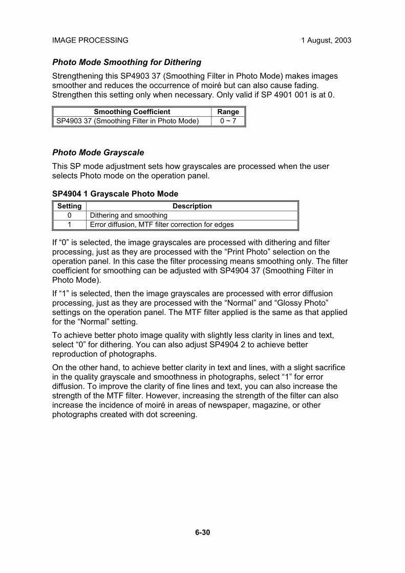
IMAGE PROCESSING 1 August, 2003
6-30
Photo Mode Smoothing for Dithering Strengthening this SP4903 37 (Smoothing Filter in Photo Mode) makes images smoother and reduces the occurrence of moiré but can also cause fading. Strengthen this setting only when necessary. Only valid if SP 4901 001 is at 0.
Smoothing Coefficient Range SP4903 37 (Smoothing Filter in Photo Mode) 0 ~ 7
Photo Mode Grayscale This SP mode adjustment sets how grayscales are processed when the user selects Photo mode on the operation panel.
SP4904 1 Grayscale Photo Mode Setting Description
0 Dithering and smoothing 1 Error diffusion, MTF filter correction for edges
If �0� is selected, the image grayscales are processed with dithering and filter processing, just as they are processed with the �Print Photo� selection on the operation panel. In this case the filter processing means smoothing only. The filter coefficient for smoothing can be adjusted with SP4904 37 (Smoothing Filter in Photo Mode). If �1� is selected, then the image grayscales are processed with error diffusion processing, just as they are processed with the �Normal� and �Glossy Photo� settings on the operation panel. The MTF filter applied is the same as that applied for the �Normal� setting. To achieve better photo image quality with slightly less clarity in lines and text, select �0� for dithering. You can also adjust SP4904 2 to achieve better reproduction of photographs. On the other hand, to achieve better clarity in text and lines, with a slight sacrifice in the quality grayscale and smoothness in photographs, select �1� for error diffusion. To improve the clarity of fine lines and text, you can also increase the strength of the MTF filter. However, increasing the strength of the filter can also increase the incidence of moiré in areas of newspaper, magazine, or other photographs created with dot screening.

1 August, 2003 IMAGE PROCESSING
6-31
Det
aile
dD
escr
iptio
ns
Photo Mode Image Quality This section describes how to select a setting to improve image quality in the Photo mode with dithering in order to create an extremely smooth photo image. Generally, a larger dithering matrix uses rougher dither pattern to reproduce a smoother gray image, but lowering the resolution can make text and lines more difficult to see. Conversely, a smaller dithering matrix uses a finer dithering pattern to reproduce a gray image of rougher texture, but raising the resolution can make text and lines easier to see. SP4904 002 Quality Photo Mode
Setting Dither Pattern Picture Quality
Text Quality Processing Priority
0 8 x 8 (75 lines) High Low Dot screen areas
1 8 x 8 (106 lines) Highest Low Filled areas (highest priority) Default
2 6 x 6 (142 lines) Medium Medium Filled areas 3 4 x 4 (212 lines) Low High Resolution
For these dither adjustments to take effect, SP4904 1 (Grayscale Photo Mode) must be set to �0� to enable dithering. Here are some general rules:
• If your main concern is reproducing legible text, use the smaller matrixes, but a smaller matrix could cause spurious lines to appear in images.
• When using the smallest matrix with setting �3� (4 x 4), you should switch off the smoothing filter for the Photo mode by setting SP4903 37 to �0�.
• Use the largest dither matrix (setting �0�) for originals that contain dot screening such as newspaper and magazine photographs.

IMAGE PROCESSING 1 August, 2003
6-32
6.2.13 OTHERS
Vertical Black Line Correction This section describes how to select a setting to correct vertical black lines. SP4904 5 (Special Text Density) adjusts the overall intensity of the image to eliminate vertical black lines in originals caused by documents scanned on a copy machine with dirty optics.
SP Mode Default Range SP4904 5 Special Text Density 0 0 ~ 7
Normally, the default setting (0) leaves this feature switched off. Select a higher setting to increase the effect or a lower setting to decrease the effect. High density vertical black lines may require a higher setting, but a higher setting could cause the overall density of the copy to lower, or could cause low density areas to drop out completely. NOTE: Generally, this SP code corrects most low density vertical black lines but
may not be able to correct extremely dark or wide black lines. Density Settings This section describes how to adjust the density settings for the Pale mode Generation Copy mode, and Text mode. SP4904 3 is used to switch the density characteristics to binary digital processing for black and white originals to achieve better balance between text and images, correct shadows that appear around text in handwritten documents, to enhance documents written in pencil, or to achieve stark contrast when copying blueprints, building plans, etc. SP4903 3 Density Setting for Low Density Original Mode
Settings Density Characteristics 0 Selects γ normal density (Default). 1 Digitizes to near binary image.
SP4904 4 is used to switch between normal density and better reproduction of areas with graduated fill in originals copied in the Generation Copy mode. To improve the appearance of graduated fill areas of high density, set to �1� so the process can ignore black and more accurately reproduce areas with graduated fill. For example, the �1� setting is ideal for copying Generation Copy originals of medical charts that contain images of internal organs.

1 August, 2003 IMAGE PROCESSING
6-33
Det
aile
dD
escr
iptio
ns
SP4904 4 Density Setting for Copied Original Mode Settings Density Characteristics
0 Selects normal density (Default) for Generation Copy originals. 1 Produces better gradation in fill areas of high density.
If �1� is selected for SP4904, the following SP mode settings may also need adjustment.
SP No. Function Recommended Setting SP4903 57 Filter Level: Generation Copy 4 (or change as required) SP4903 58 Filter Strength: Generation Copy 2 (or change as required) SP4903 64 Independent Dot Erase: Generation Copy 0 (OFF) SP4903 69 Background Erase Level: Generation Copy 0 OFF SP4903 75 Line Width Correction: Generation Mode 0 (LWC OFF)
ADS Level This section shows you how to adjust the center notch for the ADS (Automatic Density Setting) level. The notches are not displayed during ADS adjustment. Of 7 steps (notches) the center notch is 4. This is the value adjusted with this SP code. SP5106 6 (ADS Level Selection) selects the image density used in ADS mode. For example, if you set SP5106 66 to �2�, pressing the Auto Image Density key toggles the display off and manual notch 2 is selected. This SP code is adjusted, if the customer cannot attain clean copies after performing automatic density adjustment. This mode prevents the background of an original from appearing on copies. The copier scans the auto image density detection area, a narrow strip at one end of the main scan line. As the scanner scans down the page, the IPU on the BICU detects the peak white level for each scan line in this narrow strip only. The IPU uses this peak white level as a reference value for analog-to-digital conversion of the scan line, then the IPU sends the reference value to the A/D controller on the SBU. When an original with a gray background is scanned, for example, the density of the gray area becomes the peak white level density, so the original background will not appear on copies. Because peak level data is taken for each scan line, ADS corrects for any changes in background density down the page. As with previous digital copiers, the user can select manual image density when selecting auto image density mode and the machine will use both settings when processing the original.

IMAGE PROCESSING 1 August, 2003
6-34
6.2.14 PRACTICAL APPLICATION OF SP MODES
Solving Problems This section describes some common problems that can be solved with SP code adjustments. This table lists the recommended settings; fine adjustments may be required for the actual type of originals that the customer is copying. NOTE: To do the settings in the table below, first you must set the Master SP code
to �0�. (☛�FILTERING�, 6-23~6-31)
Job User Tool Custom Setting Adjustment Eliminate blue lines from graph paper, or erase shadows caused by originals that have been pasted up for layout.
• Lighten the image density for Text mode.
• Select �Soft� for Text mode (User Tools).
• Increase the setting of SP4903 60 (Independent Dot Erase) to about 6 ~ 10.
• Increase the setting of SP4903 65 (Background Erase) to about 20 ~ 60.
Eliminate orange or other color backgrounds from official documents.
• Increase the setting of SP4903 60 (Independent Dot Erase) to about 10 ~ 15.
• Increase the setting of SP4903 65 (Background Erase) to about 120 ~ 160.
Reproduce blue lines of graph paper.
• Darken the image density for Text/Photo mode.
• Select �Sharp� for the Text/Photo mode (User Tools).
De-emphasize fine lines in jagged valleys and reduce the occurrence of moiré.
• Select �Soft� for Text mode (User Tools).
Weaken the MTF filters for Text mode: • SP4903 24, Main Scan: 9 • SP4903 25, Sub Scan: 13 • SP4903 26, Main Scan: 2 • SP4903 27, Sub Scan: 2
Reduce the occurrence of moiré when reducing the size of the original for copying.
• Select �Soft� for Text mode (User Tools).
Weaken the MTF filters for Text mode reduction: • SP4903 20, Main Scan: 14 • SP4903 21, Sub Scan: 13 • SP4903 22, Main Scan: 1 • SP4903 23, Sub Scan: 1
Reproduce areas of graduated fill in high density originals in Photo mode.
• Select �Glossy Photo� for Photo mode (User Tools).
Sharpen text in Photo mode. • Select �Normal� or �Glossy Photo� for Photo mode (User Tools).
Set SP4904 1 to �1� to enable error diffusion. Strengthen the settings for the Photo mode MTF filters coefficients: • SP4903 36: Select �3� • SP4903 38: Select �1�
Improve the appearance of originals handwritten with pencil, or make lighter copies of color originals (invoices and other commonly used business forms)
• Select �Sharp� for Pale mode (User Tools).
• Select �Sharp� for Text mode (User Tools).
Strengthen the MTF filters for Pale mode: • SP4903 55: Select �3� • SP4903 56: Select �4� Strengthen the MTF filters for Text mode: • SP4903 24: Set to �9�. • SP4903 25: Set to �13�. • SP4903 26: Set to �3�. • SP4903 27: Set to �3�.

1 August, 2003 IMAGE PROCESSING
6-35
Det
aile
dD
escr
iptio
ns
Recommended Settings for MTF Filters Text Mode � Text Mode Filter Setting (25% ~ 64%) �
MTF Strength Strong ←←←← Default →→→→ Weak Default Settings: Sharp Normal Soft
SP4903 20 Main Filter Level: Text 15 14 12 10 9 9 14 10 9 SP4903 21 Sub Filter Level: Text 13 13 12 12 13 10 13 13 10 SP4903 22 Main Filter Strength 2 2 2 2 2 2 1 1 1 SP4903 23 Sub Filter Strength: Text 2 2 2 2 2 2 1 1 1
�Text Mode Filter Setting (65% ~ 154%) � MTF Strength Strong ←←←← Default →→→→ Weak
Default Settings: Sharp Normal Soft SP4903 24 Main Filter Level 9 9 15 14 12 10 9 14 11 SP4903 25 Sub Filter Level 13 11 13 13 13 13 13 13 13 SP4903 26 Main Filter Strength 3 3 2 2 2 2 2 1 1 SP4903 26 Sub Filter Strength 3 3 2 2 2 2 2 1 1
�Text Mode (155% ~ 256%) � MTF Strength Strong ←←←← Default →→→→ Weak
Default Settings: Sharp Normal Soft SP4903 28 Main Filter Level 11 10 9 9 14 12 10 9 9 SP4903 29 Sub Filter Level 13 13 13 10 13 13 13 13 10 SP4903 30 Main Filter Strength 3 3 3 3 2 2 2 2 2 SP4903 31 Sub Filter Strength 3 3 3 3 2 2 2 2 2
�Text Mode (257% ~ 400%) � MTF Strength Strong ←←←← Default →→→→ Weak
Default Settings: Sharp Normal Soft SP4903 32 Main Filter Level 12 11 10 9 15 14 12 10 9 SP4903 33 Sub Filter Level 13 13 13 13 13 13 13 13 13 SP4903 34 Main Filter Strength 3 3 3 3 2 2 2 2 2 SP4903 35 Sub Filter Strength 3 3 3 3 2 2 2 2 2

IMAGE PROCESSING 1 August, 2003
6-36
Pale Mode MTF Strength Strong ←←←← Default →→→→ Weak
Default Settings: Sharp Normal Soft SP4903 55 Filter Level: Light Original 5 4 3 2 6 4 3 2 6
SP4903 56 Filter Strength: Light Original 4 4 4 4 3 3 3 3 2
Generation Copy Mode
MTF Strength Strong ←←←← Default →→→→ Weak Default Settings: Sharp Normal Soft
SP4903 55 Filter Level: Light Original 2 6 5 4 3 2 6 5 4
SP4903 56 Filter Strength: Light Original 2 2 2 2 2 2 1 1 1

1 August, 2003 PHOTOCONDUCTOR UNIT (PCU)
6-37
Det
aile
dD
escr
iptio
ns
6.3 PHOTOCONDUCTOR UNIT (PCU) 6.3.1 OVERVIEW
1. Toner Collection Coil 2. Toner Collection Plate 3. Image Density Sensor 4. Pick off Pawl
5. OPC Drum (φ60 mm) 6. Transfer Entrance Guide
7. Charge Roller 8. Charge Roller Cleaning Roller 9. Drum Cleaning Blade 2 10. Quenching Lamp 11. Drum Cleaning Blade 1
B135D911.WMF
1 2 3
4
5
6
7
8
9
10
11

PHOTOCONDUCTOR UNIT (PCU) 1 August, 2003
6-38
6.3.2 DRUM CLEANING
The PxP (Polyester Polymerization) toner of this machine is of much finer particle size so in addition to the stationary cleaning blade, mounted with two screws at the bottom of the PCU, an additional cleaning blade [A] has been added to increase the efficiency of drum cleaning. The new cleaning blade is held in contact with the drum by two small springs [B] (one on each end) that keep the cleaning blade in contact with the drum. This cleaning blade is not a counter blade. Every time the PCU is opened for replacement or cleaning, the spring closest to the front of the PCU must moved in order to retract the cleaning blade away from the OPC drum. After cleaning or replacement, the spring must be returned to its original position to keep the blade in contact with the OPC drum for normal operation. For details, see Section �3 Replacement and Adjustment�.
B135D912.WMF
[A] [B]
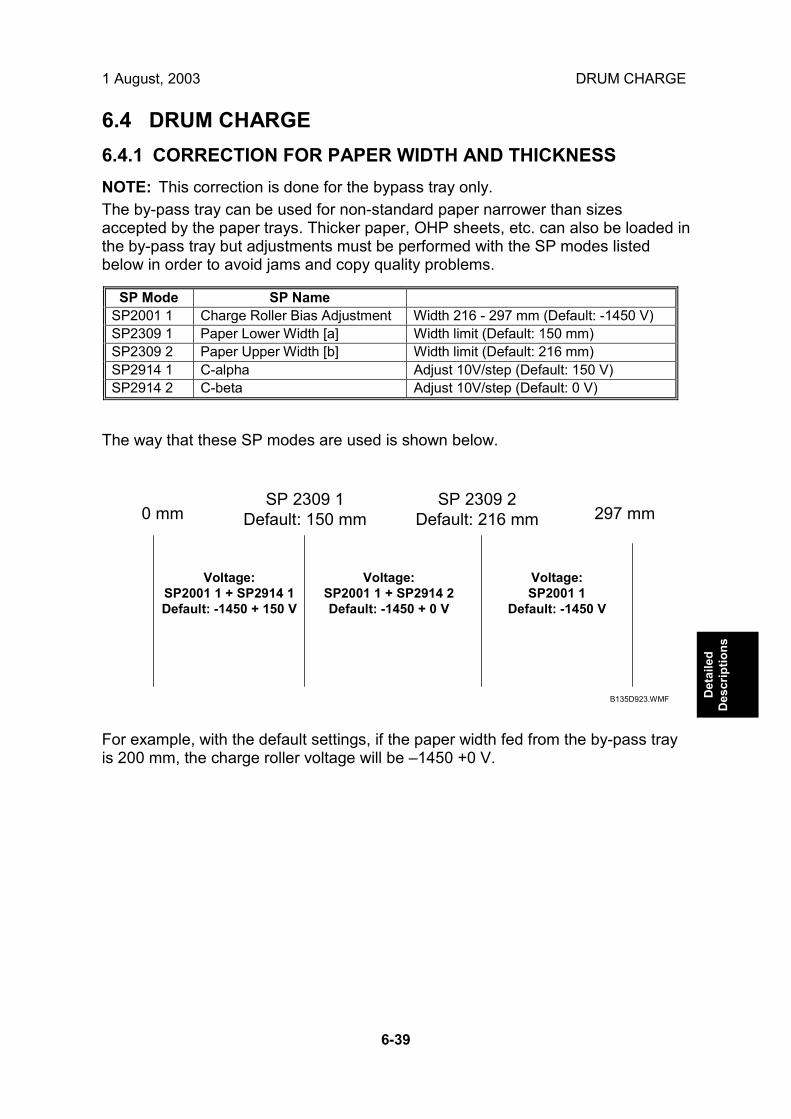
1 August, 2003 DRUM CHARGE
6-39
Det
aile
dD
escr
iptio
ns
6.4 DRUM CHARGE 6.4.1 CORRECTION FOR PAPER WIDTH AND THICKNESS NOTE: This correction is done for the bypass tray only. The by-pass tray can be used for non-standard paper narrower than sizes accepted by the paper trays. Thicker paper, OHP sheets, etc. can also be loaded in the by-pass tray but adjustments must be performed with the SP modes listed below in order to avoid jams and copy quality problems.
SP Mode SP Name SP2001 1 Charge Roller Bias Adjustment Width 216 - 297 mm (Default: -1450 V) SP2309 1 Paper Lower Width [a] Width limit (Default: 150 mm) SP2309 2 Paper Upper Width [b] Width limit (Default: 216 mm) SP2914 1 C-alpha Adjust 10V/step (Default: 150 V) SP2914 2 C-beta Adjust 10V/step (Default: 0 V)
The way that these SP modes are used is shown below.
For example, with the default settings, if the paper width fed from the by-pass tray is 200 mm, the charge roller voltage will be �1450 +0 V.
0 mmSP 2309 1
Default: 150 mmSP 2309 2
Default: 216 mm 297 mm
Voltage:SP2001 1 + SP2914 1Default: -1450 + 150 V
Voltage:SP2001 1 + SP2914 2Default: -1450 + 0 V
Voltage:SP2001 1
Default: -1450 V
B135D923.WMF

DRUM CHARGE 1 August, 2003
6-40
6.4.2 DEVELOPMENT BIAS
Mechanism Black areas of the latent image are at a low negative charge (about �150 V) and white areas are at a high negative charge (about �950 V). To attract negatively charged toner to the black areas of the latent image on the drum, the high voltage supply board [A] applies a bias of �510 volts to the development roller throughout the image development process. The bias is applied to the development roller shaft [B] through the bias terminal spring [C] and bias terminal [D]. The development bias voltage (-510 V) can be adjusted with SP2-201 (Development Bias). Correction for paper width and thickness (by-pass tray only) The by-pass tray can be used for non-standard paper narrow than sizes accepted by the paper trays. Thicker paper, OHP sheets, etc. can also be loaded in the by-pass tray but adjustments must be performed with the SP modes listed below in order to avoid jams and misfeeds.
SP Mode SP Name SP2201 1 Development Bias Width 216 - 297 mm (Default: -510V) SP2309 1 Paper Lower Width [a] Width limit (Default: 150 mm) SP2309 2 Paper Upper Width [b] Width limit (Default: 216 mm) SP2914 3 Process Control Setting (Bγ) Adjust 10V/step (Default: 200V) SP2914 4 Process Control Setting (Bδ) Adjust 10V/step (Default: 50V)
The way that these SP modes are used is shown below.
For example, with the default settings, if the paper width fed from the by-pass tray is 200 mm, the development bias voltage will be �510 + 50 V.
B135D914.WMF
0 mm SP 2309 1Default: 150 mm
SP 2309 2Default: 216 mm 297 mm
Voltage:SP2201 1 + SP2914 3Default: -510 + 200 V
Voltage:SP2201 1 + SP2914 4Default: -510 + 50 V
Voltage:SP2201 1
Default: -510 V
B135D915.WMF
[A]
[B]
[C]
[D]

1 August, 2003 PAPER FEED
6-41
Det
aile
dD
escr
iptio
ns
6.5 PAPER FEED 6.5.1 PAPER REGISTRATION
The registration drive roller [A] and idle roller [B] correct the skew of the paper to ensure that the leading edge of the paper is positioned correctly at the drum. The paper feed/development motor [C] drives the registration mechanism. The registration sensor [D] is positioned just before the registration rollers. When the leading edge activates the registration sensor, the registration clutch is switched off and the registration rollers stop turning. However, the relay clutch [E] remains on slightly longer. This delay allows more time for the paper to press against the registration rollers and buckle slightly to correct any skew. The registration sensor also detects misfeeds. Next, the registration clutch [F] actuates and the relay clutch at the correct time to align the paper with the image on the drum. The registration rollers then feed the paper to the image transfer section. Two new dust blades have been added around the registration roller. The idle roller dust blade [G] cleans the registration idle roller. This dust blade has a small dust box that collects paper dust that must be emptied periodically. The registration roller dust blade [H] cleans the registration roller. For details about how to remove and clean these new parts, see Section �3 Replacement and Adjustment�.
B135D916.WMF
[A]
[B]
[C]
[F]
[D] [E][G] [H]

IMAGE FUSING AND PAPER EXIT 1 August, 2003
6-42
6.6 IMAGE FUSING AND PAPER EXIT 6.6.1 CLEANING MECHANISM
The cleaning roller [A], in constant contact with the pressure roller [B], collects toner and paper dust from the surface of the pressure roller. Because the cleaning roller is metal, it can collect adhering matter better than the pressure roller, which is coated with Teflon. Some new design features have been implemented in order to cope with the lower temperatures required for new toner which has a melting temperature much lower than the previous toner. The cleaning roller [A] is composed of an aluminum shell with an internal �heat pipe� suspended in the middle of the roller to dissipate heat more rapidly.
B135D917.WMF
[A]
[B]

1 August, 2003 IMAGE FUSING AND PAPER EXIT
6-43
Det
aile
dD
escr
iptio
ns
6.6.2 HOT ROLLER STRIPPER CLEANING
Toner clinging to the hot roller strippers can cause black dots to appear on the back sides of copies so the widths of the strippers have been reduced from 3 mm to 0.5 mm. In addition to this design change, the hot roller strippers are cleaned by switching the fusing/exit motor off/on to rotate the hot roller and dislodge any toner clinging to these strippers. When printing ends, the fusing/exit motor switches off for 15 sec. then switches on for 15 sec. This on/off cycle is repeated for the number of times specified with SP3905 1 (Default: 1 off/on cycle). While the fusing/exit motor is switched off/on during the cleaning cycle, all fans remain on. The hot roller strippers are also force cleaned by adjusting and raising the setting of SP5959 (Image Timing Adjustment) which allows the drum and hot roller to turn freely to allow more time for cleaning before printing. However, make sure that the customer understands that increasing this SP setting slows down the first print time. These are the SP codes that control hot roller stripper cleaning. (For details, refer to Section �5. Service Tables�.
No. Name Function
SP3905 1 Number of Rotations
Prescribes the number of times the hot roller is rotated at the end of the print job if the print job exceeds the number of pages specified with SP3905 2. (Default: 1)
SP3905 2 Number of Pages
Prescribes the number of pages to print and trigger hot roller stripper cleaning. Cleaning executes only if the number of pages in the print job exceeds this number. (Default: 15 pp.)
The timing chart below shows the fusing/exit motor switched off and on twice at the end of a print job.
Print Job End
Fusing/Exit motor
FusingTemperature
15 sec. 15 sec.
Off/On 1 Off/On 2
1 min.
Re-load Temperature
B135D918.WMF

IMAGE FUSING AND PAPER EXIT 1 August, 2003
6-44
Here are some important points to keep in mind about hot roller stripper cleaning: • If a request to start a print job is received during cleaning cycle in the timing chart
above, cleaning stops and the new print job starts. During a normal print job, the fusing/exit motor switches on as soon as the paper reaches the registration roller, but in this case the fusing/exit motor remains on.
• If a request to enter the Off mode is received while hot roller stripper cleaning is in progress, the machine enters the Off mode and the cleaning cycle stops immediately.
• If the machine switches to any of the energy saver modes (low power mode, etc.) the cleaning cycle completes and does not halt.
• The cleaning cycle is not interrupted during free rotation of the hot roller when the machine is getting ready to print.
• Opening the front door, however, will stop the cleaning cycle.

1 August, 2003 IMAGE FUSING AND PAPER EXIT
6-45
Det
aile
dD
escr
iptio
ns
6.6.3 FUSING TEMPERATURE CONTROL
The fusing unit has two fusing lamps: the first fusing lamp (center: 650W) [A] heats the center of the fusing roller, and the second fusing lamp (ends: 550W) [B] heats both ends of the hot roller. This arrangement ensures even heat on all surfaces of the roller. In order to control the temperature of the roller, two high response thermistors are attached to the unit, one near the center [C] and one at the end [D] of the hot roller.
B135D919.WMF [A]
[B]
[C]
[D]

IMAGE FUSING AND PAPER EXIT 1 August, 2003
6-46
Temperature Control
There are two types of temperature control: • On/off control (Default) • Phase control. Either mode can be selected with SP1104 (Fusing Temperature Control). After the machine is powered on, the CPU checks the ac frequency for 500 ms, in case phase control is selected later for the temperature control, and then switches on the fusing lamp. As soon as both the center and end thermistors detect the print ready temperature (also known as the �re-load� temperature), the machine can operate. The �reload� temperature is 3 °C below the fusing temperature (this depends on the settings of SP1105 1~4, 7, 8). As soon as the thermistors detect the fusing temperature, the CPU switches the lamps off but frequently switches on/off again in order to maintain the fusing temperature. The default temperatures of SP1105 for these models are set 10 ~ 30 degrees lower than the temperatures for the previous machines. Some new SP codes have been added and others removed. For details, see Section �5. Service Tables�.
CenterEnd
Cen
ter
End
160°C150°C
Main SW ON Re-load
50
200
130
100
°C
120
Fusing Temp.
B079 (35 cpm)
CenterEnd
Cen
ter
End
175°C170°C
Main SW ON Re-load
50
200
140
100
°C
145
Fusing Temp.B082 (45 cpm)
B135D920.WMF

1 August, 2003 IMAGE FUSING AND PAPER EXIT
6-47
Det
aile
dD
escr
iptio
ns
Fusing Idling Temperature If copies are not sufficiently fused soon after the main power switch is turned on, fusing idling should be enabled with SP1103 1. When fusing idling is enabled, it is done when the temperature reaches the print ready (�re-load�) temperature. The re-load temperature can be adjusted with SP1105 5,6. In the opposite case, even if fusing idling is disabled, it is done when the temperature at power-up ≤ 15 °C The fusing idling time is as follows.
Fusing Idling Mode Temperature at power-on 0: Disabled 1: Enabled SP1103 1
15 °C or less 30 s 30 s Higher than 15°C Not done 30 s SP1103 2

IMAGE FUSING AND PAPER EXIT 1 August, 2003
6-48
6.6.4 CPM DOWN FOR THICK PAPER
Because the fusing temperatures are set lower for the new toner which has a lower melting point, the results of printing on thick paper cannot be guaranteed at 45 cpm on the B138. Therefore, the 45 cpm line speed is adjusted down to 35 cpm as follows: • After switching from Normal to Thick Paper for printing, the machine halts
temporarily and re-starts for 35 cpm running. • If the previous job included stapling or other finisher processing, these settings
remain in effect for the next job on thick paper after the line speed is adjusted. • If the print job on thick paper does not include an image on the page (a cover),
then the speed is not adjusted down from 45 cpm to 35 cpm. NOTE: The previous machine automatically reduced line speed 30% (ppm
down) for thick paper. In these models, however, the speed is reduced from 45 cpm to 35 cpm for the 45 cpm machine. This adjustment is performed automatically for the B138 (45 cpm) machine only.
Note these other important points regarding cpm down for thick paper on the 45 cpm machine: • When the line speed switches from 45 cpm to 35 cpm for thick paper, the
transfer current changes to the settings specified with SP2301 (Transfer Current Adjustment). (For details, see Section �5. Service Tables�.) Bias voltage, development and other settings are not affected.
• Fusing temperature adjustment switches on, but no operation can start until the machine reaches the temperature specified for the job.
• The ID sensor pattern is created and the line speed remains the same until the end of the job.
• The intensity of the LD unit is lowered evenly, 30 steps from its specified value.

1 August, 2003 IMAGE FUSING AND PAPER EXIT
6-49
Det
aile
dD
escr
iptio
ns
6.6.5 COOLING AND OVERHEAT PROTECTION
The fusing unit operates at temperatures lower than the previous model in order to accommodate the new toner which has a lower melting temperature. In order to further ensure cooler running temperatures for the fusing unit, two cooling fans have been added. The side cooling fan [A] and corner cooling fan [B] switch on when the temperature of the fusing unit exceeds 150 °C and switch off when the main motor switches off.
If the hot roller temperature exceeds 230 °C for 5 seconds or more, the CPU cuts off the power to the fusing lamp, and SC543 (Fusing Overheat Error) will be displayed. Even if the thermistor overheat protection fails, there is a thermostat in series with the common ground line of the fusing lamp. If the temperature of the thermostat reaches 210 °C, the thermostat opens, removing power from the fusing lamp. At the same time, the copier stops operating. At this time, SC542 (Fusing Temperature Warm-up Error) will be displayed.
B135D921.WMF
[A]
[B]

IMAGE FUSING AND PAPER EXIT 1 August, 2003
6-50
6.6.6 TONER SCATTER PREVENTION
To reduce the incidence of toner scattering, the sponge strip has been replaced with a velvet strip [A] that extends across the length of the fusing unit, At each end of the strip [B] and [C] new seals have been added.
B135D922.WMF
[A]
[B]
[C]

1 August, 2003 SPECIFICATIONS
SPEC-1
Spec
.
SPECIFICATIONS 1. GENERAL SPECIFICATIONS
Configuration Desktop Copy Process Dry electrostatic transfer system Original Sheet/Book Original Size Maximum A3/11" x 17"
Paper tray, Duplex:
A3/11" × 17" - A5 SEF
By-pass tray: A3/11" × 17" - A6 SEF
Copy Paper Size
Non-standard sizes:
Width: 100 - 297 mm (3.9" � 11.7") Length: 148 - 432 mm (5.8" � 17.0")
Paper Tray/ Duplex:
64 - 105 g/m2 (20 - 28 lb.) Copy Paper Weight
By-pass: 52 - 163 g/m2 (16 � 44 lb.) 7R5E: Metric version (%): 400, 200, 141, 122, 115,
93, 82, 75, 71, 65, 50, 25 Inch version (%): 400, 200, 155, 129, 121, 93, 85, 78, 73, 65, 50, 25
Reproduction Ratios
Zoom: 25 ~ 400% in 1% steps B135: Copying Speed B138:
35 cpm A4, 81/2" x 11" LEF, 1-to-1 (ADF) 45 cpm, A4, 81/2" x 11" LEF, 1-to-1 (ADF)
First Copy Time B135: 4.5 s, 1st Tray, A4/81/2" x 11" LEF B138: 3.6 s, 1st Tray, A4/81/2" x 11" LEF
B135: Less than 20 s Warm-up Time B138: Less than 22 s
Continuous Copy 1~999 (operation panel entry) Paper Capacity 1,050 sheets
(500 sheets/tray x 2 with 50 sheets in by-pass tray) A4, 81/2" x 11" and smaller:
500 sheets Paper Output
B4 and larger: 250 sheets North America: 120V/60 Hz, More than 12.5 A Power Source Europe/Asia: 220 � 240 V/50, 60 Hz, More than 6.8 A
Dimensions (W x D x H)
670 mm x 650 mm x 720 mm (26.3" x 25.6" x 28.3")
Weight Less than 79 kg (174 lb.) Resolution 600 dpi (Scanning and Printing) Gradation 256 levels (Scanning and Printing) Original Archive More than 2,500 A4 pages for document server (ITU-T No. 4
Chart) Toner Replenishment Cartridge exchange (550 g) Total Counter Electric counter

SPECIFICATIONS 1 August, 2003
SPEC-2
Power Consumption Mainframe only
B135 B138 Copying Less than 1.2 kW Less than 1.2 kW Warm-up Less than 1.25 kW Less than 1.25 kW Stand-by Less than 139 W Less than 170 W Auto Off Mode Ave. 4.5 W (NA)
Ave. 5 W (EU, Asia) Ave. 4.5 W (NA) Ave. 5 W (EU, Asia)
Maximum Less than 1.44 kW (NA) Less than 1.5 kW (EU, Asia)
Less than 1.44 kW (NA) Less than 1.5 kW (EU, Asia)
Full system (including options)
B135 B138 Copying Less than 1.4 kW Less than 1.4 kW Warm-up Less than 1.3 kW Less than 1.3 kW Stand-by Less than 170 W Less than 195 W Auto Off Mode Ave. 8 W (NA)
Ave. 9 W (EU, Asia) Ave. 8 W Ave. 9 W (EU, Asia)
Maximum Less than 1.44 kW (NA) Less than 1.5 kW (EU, Asia)
Less than 1.44 kW (NA) Less than 1.5 kW (EU, Asia)
Noise Emission:
Mode Model Mainframe Only Full System Copying
B135 B138
69 dB(A) or less 70 dB(A) or less
73 dB(A) or less 74 dB(A) or less
Stand-by
B135 B138
42 dB(A) or less 42 dB(A) or less
NOTE: 1) The above measurements were made in accordance with ISO 7779. 2) Full system measurements include the ARDF, Finisher and LCT unit. 3) In the above stand-by condition, the polygonal mirror motor is not
rotating.

1 August, 2003 SPECIFICATIONS
SPEC-3
Spec
.
2. MACHINE CONFIGURATION
1. Platen cover 8. Paper tray unit 2. ARDF 9. Two-tray finisher (2 shift trays) 3. One-bin tray 10. Booklet Finisher 4. Duplex unit 11. 1000 Sheet Finisher (1 shift tray) 5. By-pass tray 12. Bridge Unit 6. LCT (Large Capacity Tray) 7. Copier
NOTE: The Bridge Unit is required for the optional finishers.
B135V901.WMF
8
1
3
4
10
2
5
11
9
7
7
12

SPECIFICATIONS 1 August, 2003
SPEC-4
Key: Symbol: U: Unique option, C: Option also used with other products
Item Key Machine Code B135 B135 B138 B138 ARDF (See Note 1.) U B541 Platen Cover (See Note 1.) C G329 Paper Tray Unit U B542 LCT (Large Capacity Tray) U B543 1-Bin Tray U B544 Bridge Unit U B538 1000-sheet Finisher (See Note 2.) C B408 Two-tray Finisher (See Note 2.) U B545 Booklet Finisher U B546 Punch Unit (See Note 3.) C B377-17 (2/3-hole) US Punch Unit (See Note 3.) C B377-27 (2/4-hole) Metric Punch Unit (See Note 3.) C B377-31 (4-hole) Northern
Europe/ Key Counter Bracket C A674 User Account Enhance Unit C B443
Copier
PI Board Kit C B669 Fax Option U B653 G3 Interface Unit U B591 Function Upgrade Board C A892 SAF Memory C G578
Fax
Handset (USA model only) C A646 Printer/Scanner Unit U B654 PostScript3 Unit U G354-17 Network Interface Board C B525-03 1394 Interface Unit C G336 USB 2.0 Interface Board C B525-01 IEEE 802.11b Wireless LAN C B515 Bluetooth C G354-04 Memory Unit 128 MB C G331
Printer/ Scanner
File Format Converter C B519-17
NOTE: 1) The ARDF and platen cover cannot be installed together. 2) The finishers require the paper tray unit and bridge unit. 3) The punch unit requires the two-tray finisher.

1 August, 2003 SPECIFICATIONS
SPEC-5
Spec
.
3. OPTIONAL EQUIPMENT ARDF (B541)
Original Size: Normal Original Mode: A3 to B6, DLT to HLT Duplex Original Mode: A3 to B5, DLT to HLT
Original Weight: Normal Original Mode: 40 ~ 128 g/m2 (11 ~ 34 lb.) Duplex Original Mode: 52 ~ 105 g/m2 (14 ~ 28 lb.)
Table Capacity: 80 sheets (80 g/m2, 20 lb.) Original Standard Position: Rear left corner Separation: Feed belt and separation roller Original Transport: Roller transport Original Feed Order: From the top original Reproduction Range: 30 ~ 200% (Sub scan direction only) Power Source: DC 24V, 5V from the copier Power Consumption: Less than 60 W Dimensions (W × D × H): 570 mm x 518 mm x 150 mm (22.4" x 20.4" x 5.9") Weight: 12 kg
PAPER TRAY UNIT (B542) Paper Size: A5 SEF to A3 SEF
51/2" x 81/2" SEF to 11" x 17" SEF Paper Weight: 64 g/m2 ~ 105 g/m2 (20 lb. ~ 28 lb.) Tray Capacity: 500 sheets (80 g/m2, 20 lb. ) Paper Feed System: FRR Paper Height Detection: 4 steps (100%, 70%, 30%, Near end) Power Source: 24 Vdc, 5 Vdc (from the copier)
120 Vac: 115 V version (from the copier) 220 ~ 240 Vac: 224/240 V version (from the copier)
Power Consumption: 50 W Weight: Less than 25 kg (55.1 lb.) Size (W x D x H): 540 mm x 600 mm x 270 mm (21.3" x 23.6" x 10.6")

SPECIFICATIONS 1 August, 2003
SPEC-6
ONE-BIN TRAY (B544) Paper Size: A5 SEF to A3 SEF
51/2�x81/2� SEF to 11�x17� SEF Paper Weight: 60 g/m2 ~ 105 g/m2 (16 lb. ~ 28 lb.) Tray Capacity: 125 sheets (80 g/m2, 20 lb.) Power Source: 5 Vdc, 24 Vdc (from copier) Power Consumption: 15 W Weight: Less than 4 kg (8.8 lb.) Size (W x D x H): 470 mm x 565 mm x 140 mm (18.5" x 22.2" x 5.5")
1000 Sheet Finisher (B408) Upper Tray Paper Size A3 to A6
11" x 17" to 51/2" x 81/2" Paper Weight 60 to 157 g/m2 (16 to 42 lb.) Paper Capacity 250 sheets, A4 LEF, 81/2" x 11" SEF or smaller, 80 g/m2 (20 lb.) Lower Tray Paper Size Staple Mode Off:
A3 to B5, 11" x 17" to 51/2" x 81/2" Staple Mode On: A3, B4, A4, B5, 11" x 17" to 81/2" x 11"
Paper Weight Staple Mode Off: 60 to 157 g/m2 (16 ~ 43 lb.) Staple Mode On: 64 to 90 g/m2 (17 ~ 24 lb.) Stapler Capacity 30 sheets (A3, B4, 11" x 17", 81/2" x 14"
50 sheets (A4, B5 LEF, 81/2" x 11" Paper Capacity Staple Mode Off:
1,000 sheets, A4, 81/2" x 11" or smaller, 80 g/m2 (20 lb.) 500 sheets, A3, B4, 11" x 17", 81/2" x 14", 80 g/m2 (20 lb.)
Staple Mode On: 80 g/m2 (20 lb.) Number of Sets
Set Size 10 to 50 Size
2 to 9 10 to 30 31 to 50
A4, 81/2"x14" LEF 100 100 to 20 100 to 20 A4, 81/2"x11" SEF 100 50 to 10 50 to 10 A3, B4, 11"x17", 81/2"x14" 50 50 to 10 --- Staple Positions 1 Staple: 2 positions (Front, Rear)
2 Staples: 2 positions (Upper, Left Staple Replenishment
Cartridge (5,000 staples/cartridge)
Power Source DC 24 V, 5V (from copier) Power Consumption 50 W Weight 25 kg (55.2 lb.) Dimensions 527 x 520 x 790 mm
20.8" x 20.5" x 31.1"

1 August, 2003 SPECIFICATIONS
SPEC-7
Spec
.
TWO-TRAY FINISHER (B545) NOTE: The punch unit is an option for this machine.
Paper Size Normal/Shift Mode: A3 to A5/DLT to HLT (A6L in no shift mode and no staple mode) Staple Mode: A3 to B5/DLT to LT Punch Mode: 2 Holes: A3 to A5/DLT to HLT 3 Holes: A3 to B5/DLT to LT 4 Holes (Europe/Asia) : A3 to A5/ DLT to HLT 4 Holes (North Europe): A3 to B5/DLT to LT
Paper Weight Normal/Shift Mode: 52 g/m2 ~ 163 g/m2 (14 ~ 43 lb.) Staple Mode: 64 g/m2 ~ 90 g/m2 (17 ~ 23 lb.) Punch mode (All types): 52 g/m2 ~ 163 g/m2 (14 ~ 43 lb.)
Tray Paper Capacity Upper Tray: 500 sheets (A4S ~ A5S/LTS, 80 g/m2, 20 lb.) 250 sheets (A3 ~ A4L/DLT ~ LTL, 80 g/m2, 20 lb.) 100 sheets (A5L/HLT, 80 g/m2, 20 lb.) Lower Tray (Multi-tray Staple Mode): 1500 sheets (A4S/LTS, 80 g/m2, 20 lb.) 750 sheets (A3 ~ B5/DLT ~ LTL, 80 g/m2, 20 lb.) 500 sheets (A5S, 80 g/m2, 20 lb.) 100 sheets (A5L/HLT, 80 g/m2, 20 lb.) Lower Tray (Normal Mode): 2000 sheets (A4S/LTS, 80 g/m2, 20 lb.) 750 sheets (A3 ~ B5/DLT ~ LTL, 80 g/m2, 20 lb.) 500 sheets (A5S, 80 g/m2, 20 lb.) 100 sheets (A5L/HLT, 80 g/m2, 20 lb.)
Stapler Tray Capacity No Mixed Original Mode: 50 sheets (A4 ~ B5/LT, 80 g/m2, 20 lb.) 30 sheets (A3 ~ B4/DLT ~ LG, 80 g/m2, 20 lb.) Mixed Original Mode: 30 sheets (A4S/A3, B5S/B4, LTS/DLT, 80 g/m2, 20 lb.)
Staple Position 4 positions 1 staple: 3 positions (Front, Rear, Rear-Slant) 2 staple: 1 position
Staple Replenishment Cartridge (5,000 staples) Power Source 24 Vdc (from copier) Power Consumption 60 W Weight Less than 53 kg (116.8 lb.) (without punch unit)
Less than 55 kg (121.3 lb.) (with punch unit) Size (W x D x H) 680 mm x 620 mm x 1030 mm
(26.8" x 24.4" x 40.6")

SPECIFICATIONS 1 August, 2003
SPEC-8
Booklet Finisher (B546) Tray Modes Sizes
Proof tray A3 to A5, DLT to HLT No staple mode A3 to A5, DLT to HLT
Rear A4 SEF, LG SEF, LT SEF Front/Slant A3 SEF, A4 LEF/SEF, B4 SEF, B5
LEF, DLT SEF, LG SEF, LT LEF/SEF Rear/Slant A3 SEF, A4 LEF, B4 SEF, B5 LEF,
DLT SEF, LT LEF
Shift tray
Staple Mode
2 Staple A3 SEF, A4, LEF, B4 SEF, B5 LEF, DLT SEF, LT LEF
Paper Size
Booklet tray
Staple Mode A3 SEF, A4 SEF, B4 SEF, DLT SEF, LT SEF
Tray Weight
Stack mode 52 g/m2 to 163 g/m2, 14 to 42 lb Staple mode 64 g/m2 to 80 g/m2, 17 to 21 lb
Paper Weight
Saddle stitch mode 64 g/m2 to 80 g/m2, 17 to 21 lb 64 g/m2 to 128 g/m2, 17 to 34 lb (Cover sheet only)
Tray Modes Paper size Capacity
A4 LEF, LT LEF or shorter
150 sheets
Proof tray A4 SEF, LT SEF or longer
75 sheets
A4 LEF, LT LEF or shorter
1000 sheets No staple
A4 SEF, LT SEF or longer
500 sheet
A4 LEF, LT LEF or shorter
750 sheets, or 30 sets *2
Shift tray
A4 SEF, LT SEF or longer
500 sheets, or 30 sets *2
1-5 sheets 25 sets 6-10 sheets 15 sets
Paper Capacity*1
Booklet tray
Staple
11-15 sheets 10 sets *1: 80 g/m2, 20 lb *2: Setting DIP SW 3 No. 5 to ON releases the 30 set limit.

1 August, 2003 SPECIFICATIONS
SPEC-9
Spec
.
Modes Paper size Total capacity
A4 LEF, LT LEF or shorter 50 sheets Staple A4 SEF, LT SEF or longer 30 sheets
Staple Capacity
Saddle stitch 15 sheets Staple Position Staple mode: 4 positions
1 staple: 3 positions (Rear, Front/Slant, Rear/Slant) 2 staples: 1 position Saddle stitch mode: 2 positions, 2 staples (center), fixed position
Staple Replenishment Cartridge Staple: 5000 staples Saddle stitch: 2000 staples
Power Source 24 Vdc (from copier) Power Consumption Less than 170 W Dimensions (w x d x h)
689 x 603 x 1055 mm 27.1 x 23.7 x 41.5 in.
Weight: 49 kg (107.8 lb.) *1: 80 g/m2, 20 lb BRIDGE UNIT (B538)
Paper Size Standard sizes A6 lengthwise to A3 HLT to DLT Non-standard sizes Width: 100 to 305 mm Length: 148 to 432 mm
Paper Weight 52 g/m2 ~ 135 g/m2, 16 lb. ~ 42 lb.
LCT (B543)
Paper Size A4 (S)/LT (S) Paper Weight 60 g/m2 ~ 105 g/m2, 16 lb. ~ 28 lb. Tray Capacity 1500 sheets (80 g/m2, 20lb.) Remaining Paper Detection 5 steps (100%, 75%, 50%, 25%, Near end) Power Source 24 Vdc, 5 Vdc (from copier) Power Consumption 40 W Weight Less than 17 kg (37.5 lb.) Size (W x D x H) 390 mm x 500 mm x 390 mm
(15.4" x 19.7" x 15.4")