service instructions, sqflex - microsoft internet ... · service instructions sqflex water supply...
TRANSCRIPT

Service instructions
SQFlex water supply systems
1 / 66
Table of contents1. SQFlex components ........................................................................................................................ 2
1.1 Pumps................................................................................................................................................ 2
1.2 Motor.................................................................................................................................................. 5
1.3 Control and switch boxes................................................................................................................... 6
1.4 Solar modules.................................................................................................................................. 13
1.5 Wind turbine..................................................................................................................................... 24
2. Start-up ........................................................................................................................................... 28
3. Maintenance ................................................................................................................................... 29
3.1 Solar modules.................................................................................................................................. 29
3.2 Wind turbine..................................................................................................................................... 30
4. Trouble-shooting ........................................................................................................................... 32
4.1 Solar-powered system ..................................................................................................................... 34
4.2 Solar-powered system with CU 200 control unit and level switch ................................................... 36
4.3 Solar-powered system with generator back-up ............................................................................... 38
4.4 Wind-powered system ..................................................................................................................... 40
4.5 Wind-powered system with CU 200 control unit and level switch.................................................... 42
4.6 Combined system ............................................................................................................................ 44
4.7 Combined system with CU 200 control unit and level switch .......................................................... 46
4.8 Options with generator as back-up source ...................................................................................... 49
5. Service of pump and motor .......................................................................................................... 51
5.1 General information ......................................................................................................................... 51
5.2 Service tools .................................................................................................................................... 52
5.3 Torques and lubricants .................................................................................................................... 54
5.4 Helical pump type ............................................................................................................................ 55
5.5 Centrifugal pump and motor ............................................................................................................ 56
5.6 Centrifugal pump type with splined shaft ......................................................................................... 57
5.7 Centrifugal pump type with cylindrical shaft..................................................................................... 58
5.8 Checking and replacing wear parts of centrifugal pumps ................................................................ 59
5.9 Testing the pump by means of CU 200 SQFlex control unit............................................................ 60
sqflex_SI_US_WG.book Page 1 Tuesday, September 28, 2004 7:51 AM

sqflex_SI_US_WG.book Page 2 Tuesday, September 28, 2004 7:51 AM
1. SQFlex components
1.1 PumpsTwo pump types are used, the helical rotor pump type and the centrifugal pump type.
Nameplate, helical rotor pump
The nameplate is engraved into the pump sleeve.
Key to nameplate, helical rotor pump
TM
02 6
973
2103
Fig. 1 Nameplate, helical rotor pump
Pos. Code Description
1 PROD. NO. 96078012 Product number
MODEL A Pump generation
P1 0110 Production code - Bjerringbro (P1) + production year and week
2 xx SQF - x Type designation, see section Type key on page 4
3 • Weight: x,x kg
• MADE IN DENMARK
• CE
• Pump net weight
• Country of origin
• Mark of approval.
4 Rp 1 1/4 Type and size of connecting thread
Weight x,x kgMADE IN DENMARK
PROD. NO.MODEL A
Rp 1 1/4
xx SQF -x
96078012P1 0110
1
2
3
4
2 / 66
sqflex_SI_US_WG.book Page 3 Tuesday, September 28, 2004 7:51 AM
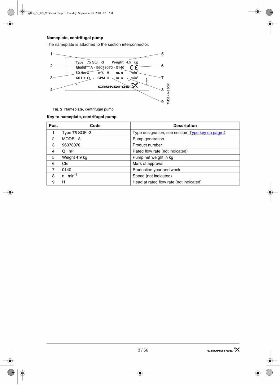
Nameplate, centrifugal pump
The nameplate is attached to the suction interconnector.
Key to nameplate, centrifugal pump
TM
02 4
149
5001
Fig. 2 Nameplate, centrifugal pump
Pos. Code Description
1 Type 75 SQF -3 Type designation, see section Type key on page 4
2 MODEL A Pump generation
3 96078070 Product number
4 Q m³ Rated flow rate (not indicated)
5 Weight 4.9 kg Pump net weight in kg
6 CE Mark of approval
7 0140 Production year and week
8 n min-1 Speed (not indicated)
9 H Head at rated flow rate (not indicated)
Type Weight KgModel50 Hz: Q60 Hz: Q GPM H
m3/. H m. n min-1
min-1
984
457m. n
75 SQF -3A - 96078070 - 0140
4,9
1
2
3
4
5
6
7
8
9
3 / 66

sqflex_SI_US_WG.book Page 4 Tuesday, September 28, 2004 7:51 AM
Type key
The type key is common for helical rotor pump and centrifugal pump.
Centrifugal pumps come in two main types: with splined pump shaft and with cylindrical pump shaft. 25 SQF-3 and 25 SQF-6 have a splined pump shaft. 40 SQF-3 and 75 SQF-3 have a cylindrical shaft.
X SQF - X
Rated flow rate in US GPM at 3000 min-1 (approximate value)
• 3 = helical rotor pump
• 6 = helical rotor pump
• 11 = helical rotor pump
• 25 = centrifugal pump
• 40 = centrifugal pump
• 75 = centrifugal pump
Type range
Number of stages
4 / 66

sqflex_SI_US_WG.book Page 5 Tuesday, September 28, 2004 7:51 AM
1.2 MotorThe MSF 3 motor is a sealed construction made of stainless steel. It is a brushles, electronically commutat-ed DC-motor with a permanent-magnet rotor (PM-motor).
Nameplate, motor
The nameplate is engraved into the stator sleeve.
TM
02 2
452
0202
Fig. 3. Nameplate, motor
Key to nameplate, motor
Pos. Code Description
1 MSF 3 Type designation
2
PROD. NO. 96040989 Product number
MODEL A Pump generation
P1 0110 Production code - Bjerringbro (P1) + production year and week
3
VDC: 30-300 VVAC: 1 x 90-240 V
The motor can be supplied with either DC or AC voltage:
• DC: 30-300 V or
• AC: 1 x 90-240 V
P1: 0.9 kW Maximum input power [kW]
I: 7 A Maximum input current [A]
S1/40 C Suitable for continuous operation up to 40°C
4CONT. DUTY 104F Suitable for continuous operation at 104°F
Ins Cl F Code A Insulation class F. Start-kVA is 0-3.15 per hp
5 PF 1.0 RPM 500 - 3000 Power factor = 1. Rated speed 500 - 3000 min-1
6 IP 68 150 mEnclosure class: IP 68. Max submerged depth: 150 m
Weight 6.55/14.4 kg/lb Motor net weight in kg and pounds
7
THERMALLY PROTECTED Temperature sensor built into the electronic unit
MADE IN DENMARK Country of origin
CE Mark of approval
MADE IN DENMARKTHERMALLY PROTECTED
Weight 6.55/14.4 kg/lb
MSF3 PROD. NO.MODEL A
96040989P1 0110
1 2
Vac: 1x90-240VVdc: 30-300V
P1: 0.9 kWI: 7AS1/40 CCONT. DUTY 104FIns Cl F Code APF 1.0 RPM: 500-3000IP 68 150m6
7
5
4
3
5 / 66
sqflex_SI_US_WG.book Page 6 Tuesday, September 28, 2004 7:51 AM
1.3 Control and switch boxes
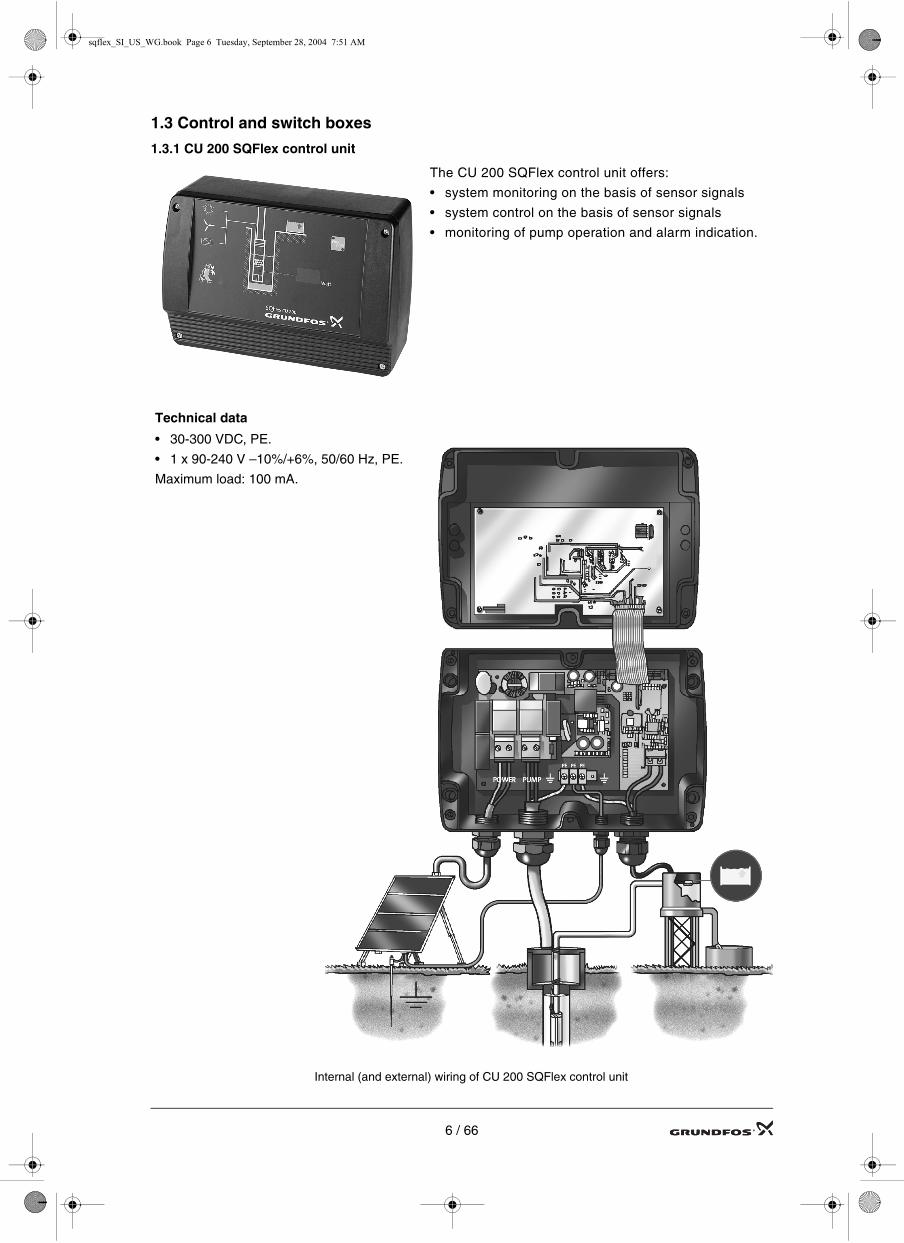
1.3.1 CU 200 SQFlex control unit
The CU 200 SQFlex control unit offers:
• system monitoring on the basis of sensor signals
• system control on the basis of sensor signals
• monitoring of pump operation and alarm indication.
Technical data
• 30-300 VDC, PE.
• 1 x 90-240 V –10%/+6%, 50/60 Hz, PE.
Maximum load: 100 mA.
Internal (and external) wiring of CU 200 SQFlex control unit
6 / 66

sqflex_SI_US_WG.book Page 7 Tuesday, September 28, 2004 7:51 AM
CU 200 SQFlex display and indicator lights
The front cover of CU 200 features a button and various indications:
ON/OFF button
• Green light on: The system has been switched on.
• Red light on: The system has been switched off.
• Both lights off: The system lacks the required power to light the display.
• Flashing green light: The sys-tem has adequate power to light the display but lacks suffi-cient power to start the pump.
Full water reservoir
The yellow light indi-cates that the water reservoir is full.Pump operation
A running green light in-dicates that the pump is operating at more than 500 min-1.
Fault indicator
Red light indicates fault. Dry running
Red light indi-cates lack of water.
Power and fault codes
The display indicates 0 Watt until the power supply is suf-ficient to run the pump at 500 rpm; upon startup, the power consumption of the pump is indicated in steps of 10 Watt, the maximum indi-cation being 990 Watt.
When the fault indicator is on, the display indicates fault codes, see Trouble-shooting by means of CU 200 on page 8.
F1 = overvoltage
F2 = overtemperature
F3 = no contact to the pump
F4 = overload
7 / 66

sqflex_SI_US_WG.book Page 8 Tuesday, September 28, 2004 7:51 AM
Trouble-shooting by means of CU 200
Indication/Fault Possible cause Remedy
1. No light in front cover.Pump does not deliver water.
No voltage supply. • Reestablish the voltage supply.
Position of ribbon cable connector is wrong orcable is defective.
• Correct the position of the cable or replace it.
2. No light in front cover, and pump does not deliver water. But the LEDs inside CU 200 indi-cating 5 V, 10 V and 24 V internal supply voltage are on, and the ‘CONTROL INDICATOR’ LED is not flashing.
CU 200 is defective. • Replace the CU 200.
3. Pump does not start.Green indicator light in ON/OFF button is on.No fault indicated.
CU 200 or pump is defec-tive.
• Check that the ‘CONTROL INDICATOR’ LED is flashing. If not, replace the CU 200.
• Check that there is sufficient voltage on the PUMP terminals. If no voltage can be measured, replace the CU 200.
If a supply voltage to the pump can be detected, continue as follows:
• Switch off the energy supply and wait for one minute.
• Switch on the energy supply and observe what happens:If the green indicator light in the ON/OFF button is on and the pump still does not start, the pump or pump cable is defective.
• Repair or replace pump or cable.4. Off light in the ON/
OFF button is on.Pump has been stopped.
• Press the ON/OFF button on the CU 200 to start the pump.
5. CU 200 indicates ‘F3 = no contact to pump’.
CU 200 defective. • Check- the connection in the CU 200- the pump cable- the end cover with socket on the pump.
Pump cable or connec-tions defective.
Pump is defective. • Repair or replace the pump.
6. CU 200 indicates ‘F1 = overvoltage’
Supply voltage is above permissible range.
• Disconnect the solar modules to allow the volt-age to drop.
• Reconfigure the modules and reconnect them.If a different supply source is used, check that the voltage is within the recommended voltage range.
Note: As the voltage is detected at the motor, allow for the voltage drop in the pump cable.
7. CU 200 indicates ‘F2 = overtempera-ture’.
Too high water tempera-ture.
• Ensure that the water temperature is below the maximum permissible level.
Incrustations on motor. • Remove incrustations on the motor.
Pump is defective. • Repair or replace the pump.
8 / 66

sqflex_SI_US_WG.book Page 9 Tuesday, September 28, 2004 7:51 AM
8. CU 200 indicates ‘F4 = overload’.
Too low input voltage. • Increase the supply voltage, to 30 VDC or higher.
Pump is defective. • Repair or replace the pump.
Only helical rotor pumps. Pumped liquid is contaminated with oil or similar substance.
• Clean the liquid and replace the pump.
Motor liquid low / Missing. • Check or refill motor liquid.
9. Green indicator light in ON/OFF button is flashing.
Insufficient power supply. • Increase the number of solar modules or con-nect an alternative energy supply, such as wind turbine, batteries or generator.
Pump has seized up. • Clean the pump.
10.Running light on CU 200 but low wattage.
System not grounded. • Check system for adequate grounding
Pump is defective. • Repair or replace the pump.If a centrifugal pump is used: Check that the riser pipe is not blocked.
11.No light in front cover. Pump delivers water.
CU 200 is defective. • Replace the CU 200.
Ribbon cable not mounted.
• Mount the ribbon cable.
12.Pump does not stop when water reservoir is full.Fault indicator light on CU 200 is off.
Level switch is dirty or defective.
• Clean or replace the level switch.
Cable on level switch is damaged.
• Replace the cable.
13.Pump does not stop when water reservoir is full. Fault indicator light on CU 200 is on.
CU 200 is defective. • Replace the CU 200.
14.Pump does not start when water reservoir is empty.Water reservoir indi-cator is on.
Level switch is defective. • Replace the level switch.
Cable on level switch is damaged.
• Replace the cable.
CU 200 is defective. • Replace the CU 200.
Indication/Fault Possible cause Remedy
9 / 66
sqflex_SI_US_WG.book Page 10 Tuesday, September 28, 2004 7:51 AM
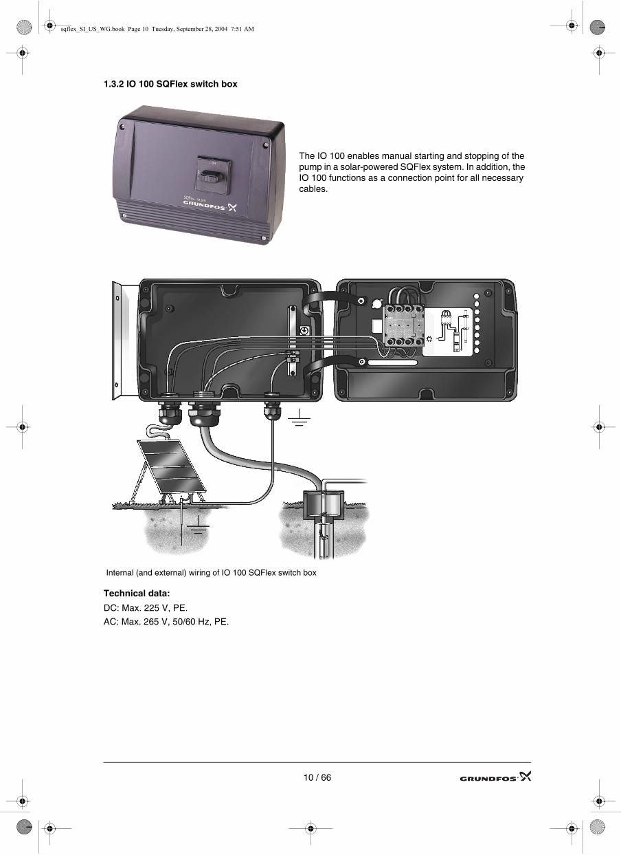
1.3.2 IO 100 SQFlex switch box
Technical data:
DC: Max. 225 V, PE.
AC: Max. 265 V, 50/60 Hz, PE.
The IO 100 enables manual starting and stopping of the pump in a solar-powered SQFlex system. In addition, the IO 100 functions as a connection point for all necessary cables.
Internal (and external) wiring of IO 100 SQFlex switch box
10 / 66
sqflex_SI_US_WG.book Page 11 Tuesday, September 28, 2004 7:51 AM
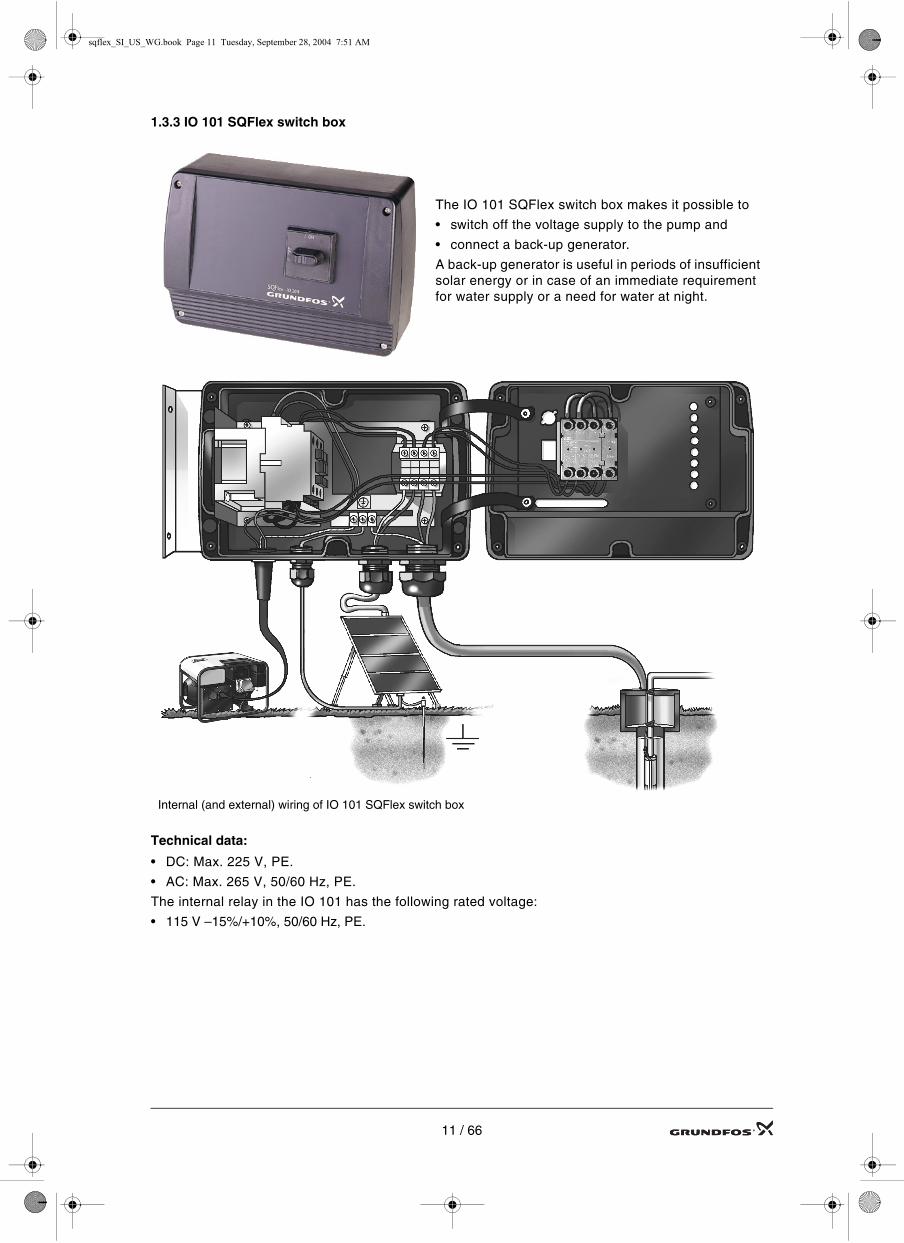
1.3.3 IO 101 SQFlex switch box
Technical data:
• DC: Max. 225 V, PE.
• AC: Max. 265 V, 50/60 Hz, PE.
The internal relay in the IO 101 has the following rated voltage:
• 115 V –15%/+10%, 50/60 Hz, PE.
The IO 101 SQFlex switch box makes it possible to
• switch off the voltage supply to the pump and
• connect a back-up generator.
A back-up generator is useful in periods of insufficient solar energy or in case of an immediate requirement for water supply or a need for water at night.
Internal (and external) wiring of IO 101 SQFlex switch box
11 / 66

sqflex_SI_US_WG.book Page 12 Tuesday, September 28, 2004 7:51 AM
1.3.4 IO 102 SQFlex breaker box
The IO 102 is applicable in SQFlex systems powered ex-clusively by a wind turbine
The IO 102 SQFlex breaker box makes it possible to
• switch off the voltage supply to the pump, and
• Stop the wind turbine blades
• connect solar modules as well as a wind turbine.
The IO 102 is applicable in SQFlex systems provided the system voltages mentioned below are not ex-ceeded.
IO 102
Technical data:
• DC: Max. 225 V, PE
• AC: Max. 265 V, 50/60 Hz, PE.
Internal (and external) wiring of IO 102 SQFlex breaker box
12 / 66

sqflex_SI_US_WG.book Page 13 Tuesday, September 28, 2004 7:51 AM
1.4 Solar modules
Positioning
Solar modules located in the northern hemisphere should face south. Use a compass to position the mod-ules as precisely as possible. Due to the magnetic declination it may be necessary to turn the modules some degrees away from the direction of the compass. In case of positive declination, turn the modules some de-grees to the west, in case of negative declination, turn the modules some degrees to the east. See Fig. 4.
Solar modules located in the southern hemisphere should face north. Use a compass to position the mod-ules as precisely as possible. Due to the magnetic declination it may be necessary to turn the modules some degrees away from the direction of the compass. In case of positive declination, turn the modules some de-grees to the east, in case of negative declination, turn the modules some degrees to the west. See Fig. 4.
Fig. 4. The map illustrates the differences in magnetic declination in different parts of the world. Declination is caused by the fact that the geographic north pole and the magnetic north pole are not located in the same place. Depending on your location on the globe you must turn the solar modules away from the direction of the compass. How much appears from the map.
Mounting
The solar modules must be mounted on a support structure.
When mounting the solar modules, make sure that the module frames overlap in order to allow for rain water to run off.
For further information on the installation of solar modules, see installation and operating instructions for the modules.
Tilt angle
For maximum utilisation of the solar radiation the tilt angle of the support structure can normally be adjusted from 15° to 45°.
13 / 66

sqflex_SI_US_WG.book Page 14 Tuesday, September 28, 2004 7:51 AM
1.4.1 GF 43, GF 50 solar modules
Visual inspection of solar modules
• Check that the solar modules are intact.
• Make sure that trees, grass, bushes, buildings, etc. do not cast a shadow on the solar modules.
The GF solar modules consist of amorphous silicon thin-film solar cells.
Each solar module is equipped with plugs and sockets for easy connec-tion of several modules in parallel. The solar panels are mounted on a support structure, tilted at an angle ensuring optimum utilisation of the solar energy.
This module is designed only for GRUNDFOS pumping systems
GRUNDFOS PART NO.: 96467737
:Current (Imp)
Minimum Bypass Diode
Open Circuit Voltage (Voc)Short Circuit Current (Isc)
:::
PART #:
Voltage (Vmp)Warranted Minimum PmaxPeak Power (Pmax)
::: W
V
AV
A
A
SERIAL #:
Product of
Electrical Ratings
Maximum Series Fuse A:
at STC (1000 W/m , AM 1.5 spectrum, cell temperature 25C)2
All values are nominal unless designated as tested
MODEL:
W
Manufactured in ISO9001 certified facility
GF 43901050
USA
43
194
615
0.40
1400.31
38.7
250
200
150
100
50
00 500 1000
T = 0°CT = 25°C
T = 50°CT = 75°C
Solar module voltage [VDC]
2Irradiance [W/m ]
0.6
0.5
0.4
0.3
0.2
0.1
0 500 1000
Solar module current [A]
2Irradiance [W/m ]
0
A mA A COM V
A
190
mV
OFF
V A
mAV
A mA A COM V
A
0,3
mV
OFF
V A
mAV
Measurement of current by means of multimeter
Measurement of voltage by means of multimeter
A = current read on the graph must be multiplied by the number of solar modules.
Example of GF 43 nameplate
14 / 66

sqflex_SI_US_WG.book Page 15 Tuesday, September 28, 2004 7:51 AM
Electrical connections GF 43, GF 50 solar modules
Note: Before making any electrical connections, make sure that the solar modules are covered with a non-transparent covering material to ensure that the modules are dead.
• The cover must be removed before measuring is made.
• Measurements must be made when the solar modules are not connected.
• The current to be measured is the short-circuit current ISC.
Note: The Grundfos GF solar modules must not be connected in series.
Fig. 5. Accessories needed to connect a PE conductor
The solar panels must be connected to earth via the Protective Earth (PE) conductor supplied with the row closure kit. The PE conductor is connected to the row closure by means of a screw terminal.
Note: To achieve good earth connection and thus to protect persons, it is of decisive importance to fit the earth clips (pos. A) and earth terminals supplied with the row closure kit.
4
3
2
1
8 9 16 17
7 10 15 18
6 11 14 19
5 12 13 20
IO 100 SQFlex
IO 101 SQFlex
IO 102 SQFlexCU 200 SQFlex
Pan
el
Module
Array
A
Row closure kit
Protective earth conductor
15 / 66
sqflex_SI_US_WG.book Page 16 Tuesday, September 28, 2004 7:51 AM
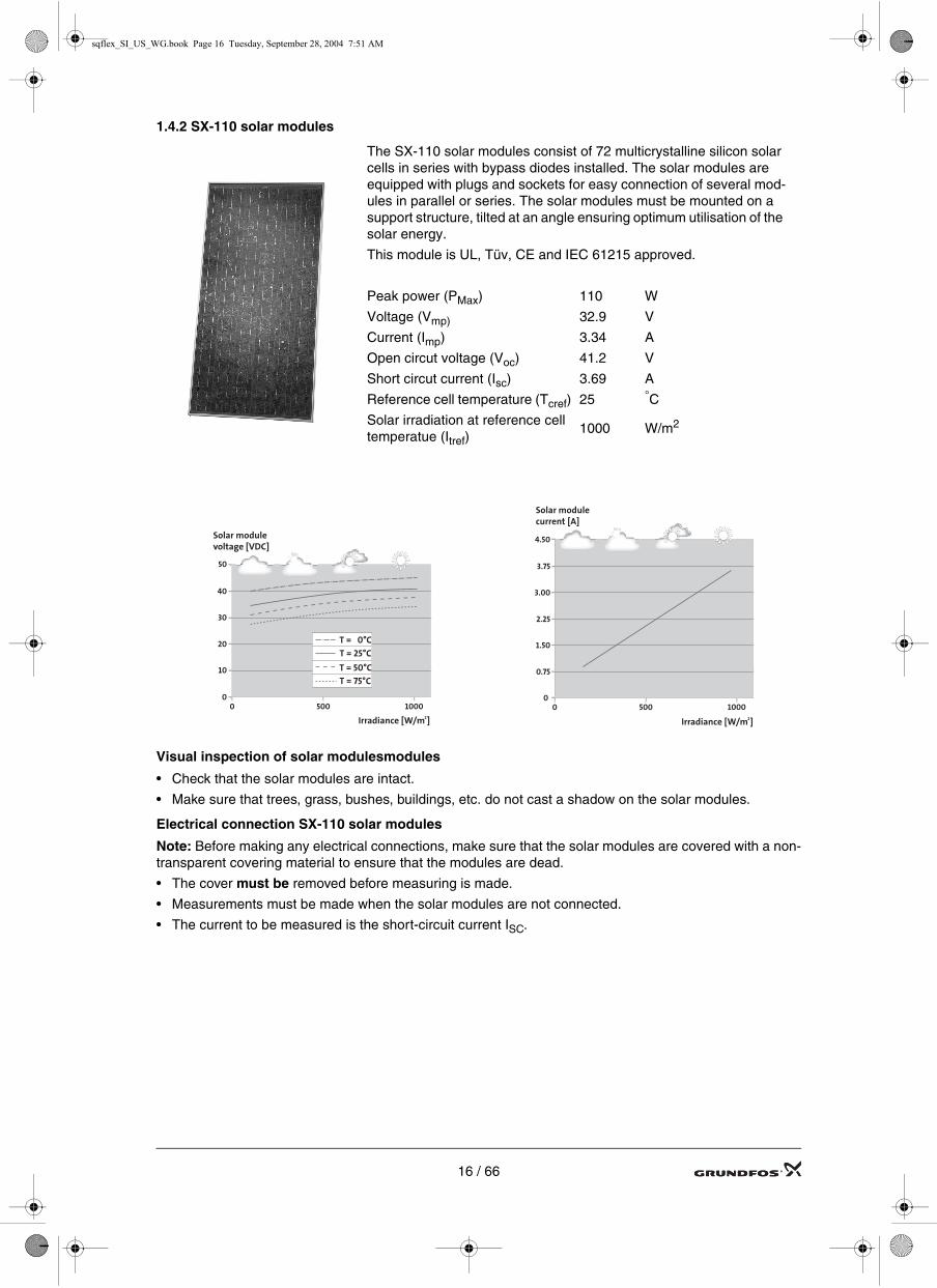
1.4.2 SX-110 solar modules
Visual inspection of solar modulesmodules
• Check that the solar modules are intact.
• Make sure that trees, grass, bushes, buildings, etc. do not cast a shadow on the solar modules.
Electrical connection SX-110 solar modules
Note: Before making any electrical connections, make sure that the solar modules are covered with a non-transparent covering material to ensure that the modules are dead.
• The cover must be removed before measuring is made.
• Measurements must be made when the solar modules are not connected.
• The current to be measured is the short-circuit current ISC.
The SX-110 solar modules consist of 72 multicrystalline silicon solar cells in series with bypass diodes installed. The solar modules are equipped with plugs and sockets for easy connection of several mod-ules in parallel or series. The solar modules must be mounted on a support structure, tilted at an angle ensuring optimum utilisation of the solar energy.
This module is UL, Tüv, CE and IEC 61215 approved.
Peak power (PMax) 110 W
Voltage (Vmp) 32.9 V
Current (Imp) 3.34 A
Open circut voltage (Voc) 41.2 V
Short circut current (Isc) 3.69 A
Reference cell temperature (Tcref) 25 °C
Solar irradiation at reference cell temperatue (Itref)
1000 W/m2
50
40
30
20
10
00 500 1000
T = 0°CT = 25°C
T = 50°CT = 75°C
Solar module voltage [VDC]
2Irradiance [W/m ]
4.50
3.75
3.00
2.25
1.50
0.75
0 500 1000
Solar module current [A]
2Irradiance [W/m ]
0
16 / 66

sqflex_SI_US_WG.book Page 17 Tuesday, September 28, 2004 7:51 AM
Electrical connection SX-110 solar modules (continued)
The solar panels must be connected to earth via a Protective Earth (PE) conductor
TM
02 6
875
1903
1
2
3
4
5
6
6
5
4
3
2
1
Plug Modules Voltage [v] Current [A]
1 - 2
3 - 45 - 6
6 - 7
12
6
1
247
247
41
7,4
3,7
3,7
67
5
3
1
2
4
1
2
3
Plug Modules Voltage [v] Current [A]
1 - 2
3 - 4
43
1 41 3,7
21
1641238241
3,73,73,73,7
3
4
1
2
3
4
Plug Modules Voltage [v] Current [A]
1 - 2
3 - 45 - 6
6 - 7
8
4
1
165
165
41
7,4
3,7
3,7
3
4
1
2
1
5
2
6
5
7
4
1
2
Plug Modules Voltage [v] Current [A]
1 - 2
5 - 6
21
4 165
3,73,7
3,7
3,7
36
3 - 4
6 - 7
76
1 41 3,7
288247
8241
7
4
5 206 3,7
1. 2.
3. 4.
17 / 66
sqflex_SI_US_WG.book Page 18 Tuesday, September 28, 2004 7:51 AM
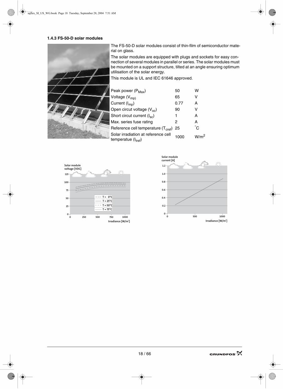
1.4.3 FS-50-D solar modules
The FS-50-D solar modules consist of thin-film of semiconductor mate-rial on glass.
The solar modules are equipped with plugs and sockets for easy con-nection of several modules in parallel or series. The solar modules must be mounted on a support structure, tilted at an angle ensuring optimum utilisation of the solar energy.
This module is UL and IEC 61646 approved.
Peak power (PMax) 50 W
Voltage (Vmp) 65 V
Current (Imp) 0.77 A
Open circut voltage (Voc) 90 V
Short circut current (Isc) 1 A
Max. series fuse rating 2 A
Reference cell temperature (Tcref) 25 °C
Solar irradiation at reference cell temperatue (Itref)
1000 W/m2
125
100
75
50
25
00 500 1000
T = 0°CT = 25°C
T = 50°CT = 75°C
Solar module voltage [VDC]
2Irradiance [W/m ]
250 750
1.2
1.0
0.8
0.6
0.4
0.2
0 500 1000
Solar module current [A]
2Irradiance [W/m ]
0
18 / 66

sqflex_SI_US_WG.book Page 19 Tuesday, September 28, 2004 7:51 AM
Visual inspection of solar modules
• Check that the solar modules are intact.
• Make sure that trees, grass, bushes, buildings, etc. do not cast a shadow on the solar modules.
Electrical connection of FS-50-D solar modules.
Note: Before making any electrical connections, make sure that the solar modules are covered with a non-transparent covering material to ensure that the modules are dead.
• The cover must be removed before measuring is made.
• Measurements must be made when the solar modules are not connected.
• The current to be measured is the short-circuit current ISC.
The solar panels must be connected to earth via a Protective Earth (PE) conductor
TM
02 6
874
1903
6
1 2
8
7
Plug Modules Voltage [v] Current [A]
1 - 2
5 - 6 4 180
4
2
3 - 4
7 - 8 1 90 1
8
201816141210
180
180180180180180180
54
3
1098765
2 180 1
36 180
19 / 66

sqflex_SI_US_WG.book Page 20 Tuesday, September 28, 2004 7:51 AM
1.4.4 GF 55C and GF 65C solar modules
Visual inspection of solar modulesmodules
• Check that the solar modules are intact.
• Make sure that trees, grass, bushes, buildings, etc. do not cast a shadow on the solar modules.
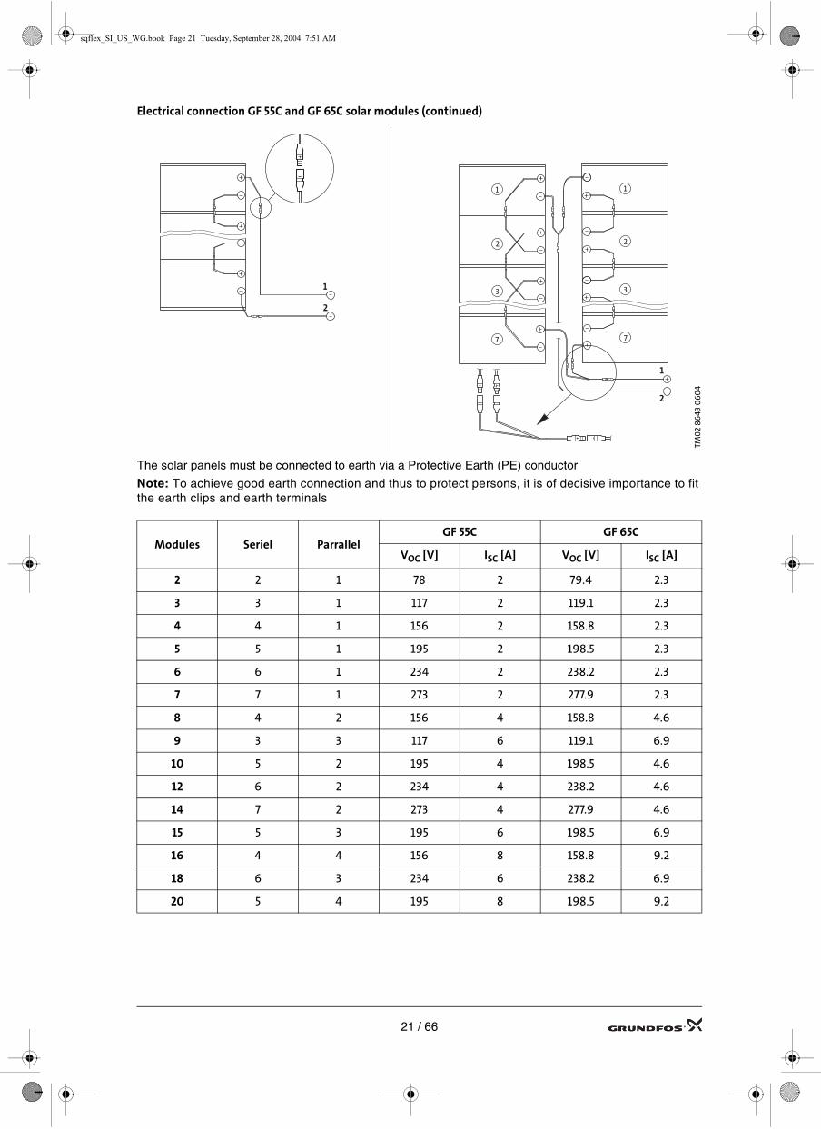
Electrical connection GF 55C and GF 65C solar modules
Note: Before making any electrical connections, make sure that the solar modules are covered with a non-transparent covering material to ensure that the modules are dead.
• The cover must be removed before measuring is made.
• Measurements must be made when the solar modules are not connected.
• The current to be measured is the short-circuit current ISC.
The GF 55C and GF65C solar modules consist of 68 multicrystalline silicon cells in se-ries. The solar modules are equipped with plugs and sockets for easy connection of several modules in parallel or series. The solar modules must be mounted on a sup-port structure, tilted at an angle ensuring optimum utilisation of the solar energy.
This module is UL, Tüv, CE and IEC 61215 approved.
GF 55C GF 65C
Peak power (PMax) 55 65 W
Voltage (Vmp) 30.6 31.4 V
Current (Imp) 1.8 2.1 A
Open circut voltage (Voc) 39.0 39.7 V
Short circut current (Isc) 2.0 2.3 A
Reference cell temperature (Tcref) 25 25 °C
Solar irradiation at reference cell temperatue (Itref)
1000 1000 W/m2
0 500 1000
T = 0°CT = 25°C
T = 50°CT = 75°C
Solar module voltage [VDC]
2Irradiance [W/m ]
50
40
30
20
10
0
0.75
0 500 1000
Solar module current [A]
2Irradiance [W/m ]
0
1.00
1.50
2.00
2.25
0 500 1000
T = 0°CT = 25°C
T = 50°CT = 75°C
Solar module voltage [VDC]
2Irradiance [W/m ]
50
40
30
20
10
0
1.50
0 500 1000
Solar module current [A]
2Irradiance [W/m ]
0
1.75
2.00
2.25
2.50
GF 55C
GF 65C
20 / 66
sqflex_SI_US_WG.book Page 21 Tuesday, September 28, 2004 7:51 AM
Electrical connection GF 55C and GF 65C solar modules (continued)
The solar panels must be connected to earth via a Protective Earth (PE) conductor
Note: To achieve good earth connection and thus to protect persons, it is of decisive importance to fit the earth clips and earth terminals
TM0
2 86
43 0
60
4
Modules Seriel ParrallelGF 55C GF 65C
VOC [V] ISC [A] VOC [V] ISC [A]
2 2 1 78 2 79.4 2.3
3 3 1 117 2 119.1 2.3
4 4 1 156 2 158.8 2.3
5 5 1 195 2 198.5 2.3
6 6 1 234 2 238.2 2.3
7 7 1 273 2 277.9 2.3
8 4 2 156 4 158.8 4.6
9 3 3 117 6 119.1 6.9
10 5 2 195 4 198.5 4.6
12 6 2 234 4 238.2 4.6
14 7 2 273 4 277.9 4.6
15 5 3 195 6 198.5 6.9
16 4 4 156 8 158.8 9.2
18 6 3 234 6 238.2 6.9
20 5 4 195 8 198.5 9.2
1
2
3
7
1
2
3
7
1
2
1
2
21 / 66
sqflex_SI_US_WG.book Page 22 Tuesday, September 28, 2004 7:51 AM
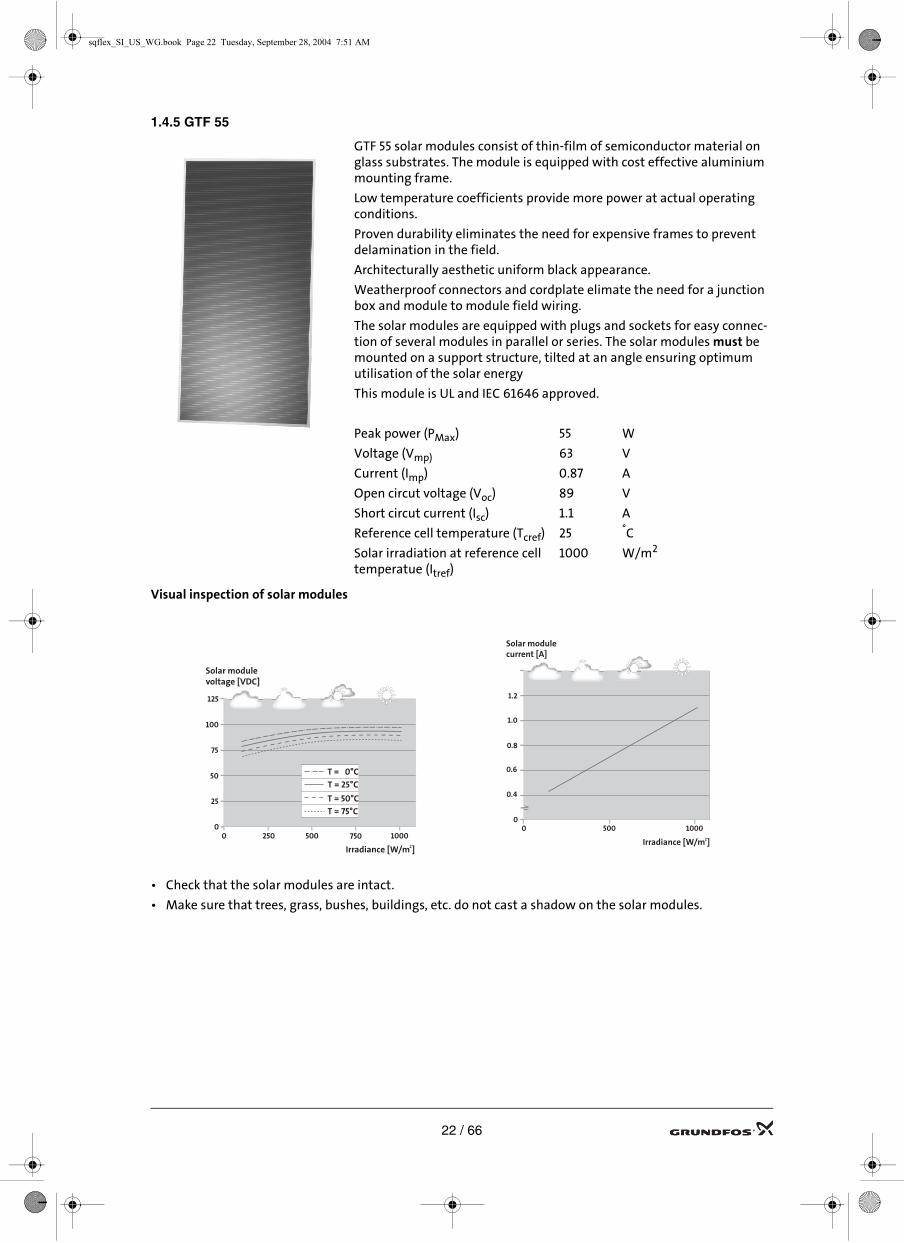
1.4.5 GTF 55
Visual inspection of solar modules
• Check that the solar modules are intact.
• Make sure that trees, grass, bushes, buildings, etc. do not cast a shadow on the solar modules.
GTF 55 solar modules consist of thin-film of semiconductor material on glass substrates. The module is equipped with cost effective aluminium mounting frame.
Low temperature coefficients provide more power at actual operating conditions.
Proven durability eliminates the need for expensive frames to prevent delamination in the field.
Architecturally aesthetic uniform black appearance.
Weatherproof connectors and cordplate elimate the need for a junction box and module to module field wiring.
The solar modules are equipped with plugs and sockets for easy connec-tion of several modules in parallel or series. The solar modules must be mounted on a support structure, tilted at an angle ensuring optimum utilisation of the solar energy
This module is UL and IEC 61646 approved.
Peak power (PMax) 55 W
Voltage (Vmp) 63 V
Current (Imp) 0.87 A
Open circut voltage (Voc) 89 V
Short circut current (Isc) 1.1 A
Reference cell temperature (Tcref) 25 °C
Solar irradiation at reference cell temperatue (Itref)
1000 W/m2
125
100
75
50
25
00 500 1000
T = 0°CT = 25°C
T = 50°CT = 75°C
Solar module voltage [VDC]
2Irradiance [W/m ]
250 7500 500 1000
Solar module current [A]
2Irradiance [W/m ]
0
1.0
1.2
0.8
0.6
0.4
22 / 66

sqflex_SI_US_WG.book Page 23 Tuesday, September 28, 2004 7:51 AM
Electrical connection of GTF 55 solar modules.
Note: Before making any electrical connections, make sure that the solar modules are covered with a non-transparent covering material to ensure that the modules are dead.
• The cover must be removed before measuring is made.
• Measurements must be made when the solar modules are not connected.
• The current to be measured is the short-circuit current ISC.
The solar panels must be connected to earth via a Protective Earth (PE) conductor
Note: To achieve good earth connection and thus to protect persons, it is of decisive importance to fit the earth clips and earth terminals
TM0
2 6
874
190
3
Pos. Product
1 Solar module GTF 55
2Cable guards and connection wire kit
3 Array-to-controller wire kit4 Array-to-array wire kit
Modules Seriel ParrallelGTF 55
VOC [V] ISC [A]
4 2 2 126 1.7
6 2 3 126 2.6
8 2 4 126 3.5
10 2 5 126 4.4
12 2 6 126 5.2
14 2 7 126 6.1
16 2 8 126 7.0
18 2 9 126 7.8
20 2 10 126 8.7
2
4
3
1
23 / 66

sqflex_SI_US_WG.book Page 24 Tuesday, September 28, 2004 7:51 AM
1.5 Wind turbine
Values measured between the three phases must be identical.
Wind turbinevoltage [VAC]
IO 102voltage [VDC]
Breaker Box IO 102V mA
AV
OFF
mV
160
A
VCOMAmAA
A mA A COM V
A
160
mV
OFF
V A
mAV
V mA
AV
OFF
mV
160
A
VCOMAmAA
A mA A COM V
A
220
mV
OFF
V A
mAV
VAC
VDC
Measurement of VAC and VDC
250
200
150
100
50
00 5
111022
m/smph
350
300
250
200
150
100
50
0
0 511
1022
m/smph
24 / 66

sqflex_SI_US_WG.book Page 25 Tuesday, September 28, 2004 7:51 AM
1.5.1 Trouble-shooting
1. Find out if the problem is mechanical or electrical.
• Propeller cannot turn = Mechanical problem, see Mechanical problems on page 26.
• Propeller turns slowly = Electrical problem, see Electrical problems on page 27.Electrical problems may be in the wind turbine or the IO 102 breaker box. Determine which as follows:
2. Disconnect the three wires from the wind turbine one at a time at the IO 102 breaker box. If the propel-ler starts, the wire that allowed it to start leads to a defective rectifier in the IO 102 breaker box. Replace the breaker box, see Overview of possible system combinations on page 33.
3. If the propeller still does not start, the problem is in the tower wiring or the wind turbine.
4. The propeller is running, but may have an electrical problem. Using a voltmeter, read the voltage across the leads and see the list below as a guide to possible problems.
• The voltage increases and decreases slowly with wind speed and equally across all wires = Every-thing OK.
• No voltage across two wires = One wire from wind turbine is not carrying power. Check in order: -the tower wiring to ensure it is properly wired.-slip rings and brushes,-stator connections and stator windings for obvious damage.
• The voltage is significantly higher across two wires than the others = Contact the distributor or the fac-tory.
• Voltage is produced even after ON/OFF switch is activated = Possibly a faulty ON/OFF switch or a wire has been short circuited to the other two wires or an internal fault has occurred in the IO 102 breaker box.
• The voltage is significantly lower across two wires than the others = Bad connection at the wind tur-bine voltage connections or faulty stator winding.
5. Should these steps not solve the problem, proceed directly to Electrical problems on page 27.
25 / 66
sqflex_SI_US_WG.book Page 26 Tuesday, September 28, 2004 7:51 AM
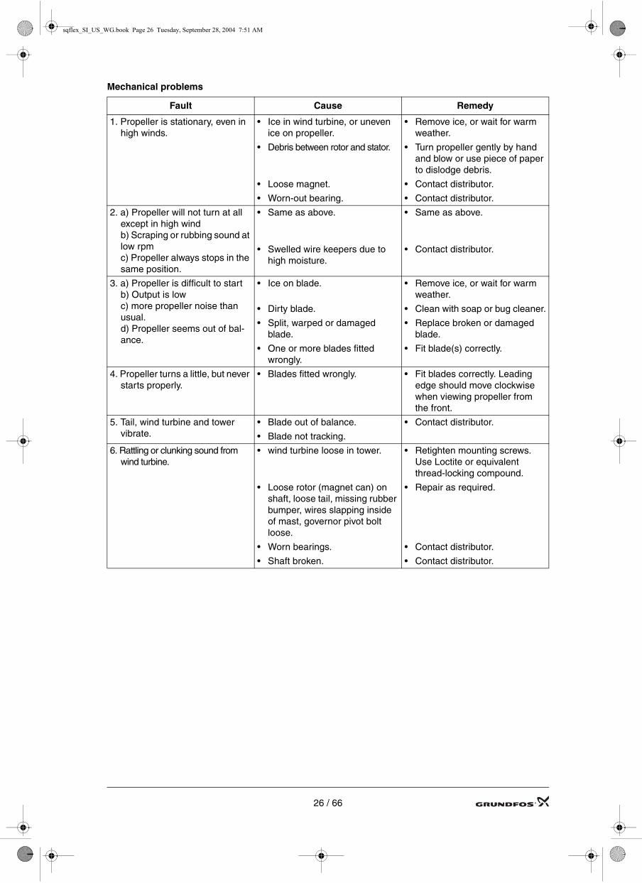
Mechanical problems
Fault Cause Remedy
1. Propeller is stationary, even in high winds.
• Ice in wind turbine, or uneven ice on propeller.
• Debris between rotor and stator.
• Loose magnet.
• Worn-out bearing.
• Remove ice, or wait for warm weather.
• Turn propeller gently by hand and blow or use piece of paper to dislodge debris.
• Contact distributor.
• Contact distributor.
2. a) Propeller will not turn at all except in high windb) Scraping or rubbing sound at low rpmc) Propeller always stops in the same position.
• Same as above.
• Swelled wire keepers due to high moisture.
• Same as above.
• Contact distributor.
3. a) Propeller is difficult to startb) Output is lowc) more propeller noise than usual.d) Propeller seems out of bal-ance.
• Ice on blade.
• Dirty blade.
• Split, warped or damaged blade.
• One or more blades fitted wrongly.
• Remove ice, or wait for warm weather.
• Clean with soap or bug cleaner.
• Replace broken or damaged blade.
• Fit blade(s) correctly.
4. Propeller turns a little, but never starts properly.
• Blades fitted wrongly. • Fit blades correctly. Leading edge should move clockwise when viewing propeller from the front.
5. Tail, wind turbine and tower vibrate.
• Blade out of balance.
• Blade not tracking.
• Contact distributor.
6. Rattling or clunking sound from wind turbine.
• wind turbine loose in tower.
• Loose rotor (magnet can) on shaft, loose tail, missing rubber bumper, wires slapping inside of mast, governor pivot bolt loose.
• Worn bearings.
• Shaft broken.
• Retighten mounting screws. Use Loctite or equivalent thread-locking compound.
• Repair as required.
• Contact distributor.
• Contact distributor.
26 / 66

sqflex_SI_US_WG.book Page 27 Tuesday, September 28, 2004 7:51 AM
Electrical problems
Note: Always be aware of the danger of high voltage. Do not directly touch the wires.
Fault Possible cause Remedy
1. Pump does not operate and pro-peller do not turn or turns slowly even in high winds.
• The wind speed is too slow.
• The IO 102 ON/OFF switch is set to OFF.
• Pump defective or pump cable short circuit.
• IO 102 is defective.
• Wait for the wind speed to increase.
• Set the IO 102 ON/OFF switch to ON.
• Set IO 102 ON/OFF switch to OFF. Disconnect the pump from IO 102. Set ON/OFF switch to ON. If the propeller starts to turn, either the pump or the pump cable is defective.Set IO 102 ON/OFF switch to OFF. Replace the defective part and reconnect to IO 102. Set ON/OFF switch to ON.
• Set IO 102 ON/OFF switch to ON. Disconnect the three wires from the wind turbine one at the time at the IO 102.if the proppeler starts to turn the IO 102 is defective. Replace the IO 102.
2. Pump does not operate and propeller turns fast.
• Wires between IO 102 and pump may be disconnected.
• Pump defective.
• Set IO 102 ON/OFF switch to OFF. Reconnect the wires.Set IO 102 ON/OFF switch to ON.
• Set IO 102 ON/OFF switch to OFF. Replace the pump.Set IO 102 ON/OFF switch to ON.
3. Pump does not operate. Pro-peller turns fast and are not alowing down when IO 102 ON/OFF switch is set to OFF.
• One or more wires between wind turbine and IO 102 may be disconnected.
• Wind turbine defective.
• IO 102 defective.
• Set IO 102 ON/OFF switch to OFF. Reconnect the wires.Set IO 102 ON/OFF switch to ON.
• Set IO 102 ON/OFF switch to OFF. Replace wind turbine.Set IO 102 ON/OFF switch to ON.
• Try to disconnect the three wires from the wind turbine in the IO 102 and short circute them. If the propeller slows down or stops, the IO 102 is defective.Replace the IO 102.
27 / 66

sqflex_SI_US_WG.book Page 28 Tuesday, September 28, 2004 7:51 AM
2. Start-upThe starting sequence has three steps:
1. Charging the capacitor
2. positioning of the rotor
3. start.
Consequently, during start-up the motor will make small rotations in order to bring the rotor into the correct starting position. These rotations also ensure that there is water in the pump and that the pump parts are lubricated.
During start-up current consumption will be uneven but when the motor has started, current consumption will be constant.
Helical rotor pumps:
• If sufficient energy is available the pump will normally be running within one minute.
• If sufficient energy is available and the motor does not start within 15 minutes, the pump rotor may be stuck due to dryness. This situation can arise if the pump has been stocked for some time. Dismantle the pump and loosen the rotor, or add water to the pump rotor/stator assembly.
• If sufficient energy is not available the starting sequence will be repeated.
Please note that after the pump has started running, it will take a while to fill the riser pipe. How long de-pends on the energy available, the installation depth and the dimensions of the riser pipe. At moderate en-ergy supply and high head, it may take up to one hour.
28 / 66

sqflex_SI_US_WG.book Page 29 Tuesday, September 28, 2004 7:51 AM
3. MaintenanceThis section describes how to maintain solar modules and wind turbines. Under normal operating conditions the pumps and the controls are maintenance-free.
3.1 Solar modulesRoutine maintenance
Cleaning
• The solar modules must be cleaned when they are dirty. Use only clean water without soap and a soft brush or cloth. Make sure there is no sand or other abrasive particles in the water.
• There is no need to clean the modules under-neath.
Clearing
• Make sure that the sun can shine directly on the modules.
• Cut down grass or trees that cast a shadow on the solar modules.
Tighten
• Tighten screws and nuts on the support struc-ture if they have loosened.
29 / 66

sqflex_SI_US_WG.book Page 30 Tuesday, September 28, 2004 7:51 AM
3.2 Wind turbine
Monthly maintenance
Test brake
(This checks electrical wiring.)Stop the wind turbine in a moderate wind (charging but not furling). No unusual difficulty or noise should be experienced in stopping the propeller. A noise during braking can indicate a disconnected wire.
Check mechanical condition
Watch and listen from the tower base.Use binoculars. The propeller and tail must not wobble. There should be no mechanical noise, rat-tle or vibration. Lower or climb the tower for inspection, if required. There should be no buzzing either heard or felt with your hand on the tower mast. Go to section Electrical problems on page 27, if required.
Inspect the tower
Follow all inspection and maintenance require-ments of the tower manufacturer. Tighten all nuts and screws, especially wire clips. Check for cracks and bent or broken parts at the anchors and base structure. Check for broken wire strands and tighten guys.
Annual maintenance
Complete mechanical check
• Lower the tower
• Repair or replace any worn or loose parts.
• Check tightness of all tower mounting nuts and screws and propeller mounting screws.
• Check all bearings. Just perceptible play is acceptable.
• Clean the propeller with mild detergent to remove all dirt and debris. Replace blades if they are cracked or damaged.
Tighten tower, tail, hub and blade mounting screws.
Do not tighten pivot pin nut.
30 / 66
31 / 66
sqflex_SI_US_WG.book Page 31 Tuesday, September 28, 2004 7:51 AM

sqflex_SI_US_WG.book Page 32 Tuesday, September 28, 2004 7:51 AM
4. Trouble-shootingVisual/general inspection of main components
Before starting specific Trouble-shooting, go through these simple visual inspections first.
Visual inspection of solar modules
• Check that the solar modules are intact.
• Make sure that trees, grass, bushes, buildings, etc. do not cast a shadow on the solar modules.
Visual inspection of the wind turbine,
see Check mechanical condition on page 30
Visual inspection of cables
• Check that the cables are intact.
Visual inspection of the water level
The water level must be at least 3 ft. above the pump.The dry running sensor must be under water.
Visual inspection of pipes and hoses
• Check that hoses or pipes are intact.
Test by means of a service CU 200
If available, a CU 200 can be used for testing sys-tems without a CU 200. Connect the CU 200 and proceed according to the instructions in section 1.3.1 CU 200 SQFlex control unit on page 6.
POWER PUMP GND INPE PE PE
F1 = OVERVOLTAGEF2 = OVERTEMPF3 = NO CONTACTF4 = OVERLOADCONTROL INDICATORMAX SPEED
+24 V+10 V+5 V
LEVEL SWITCH
32 / 66
sqflex_SI_US_WG.book Page 33 Tuesday, September 28, 2004 7:51 AM
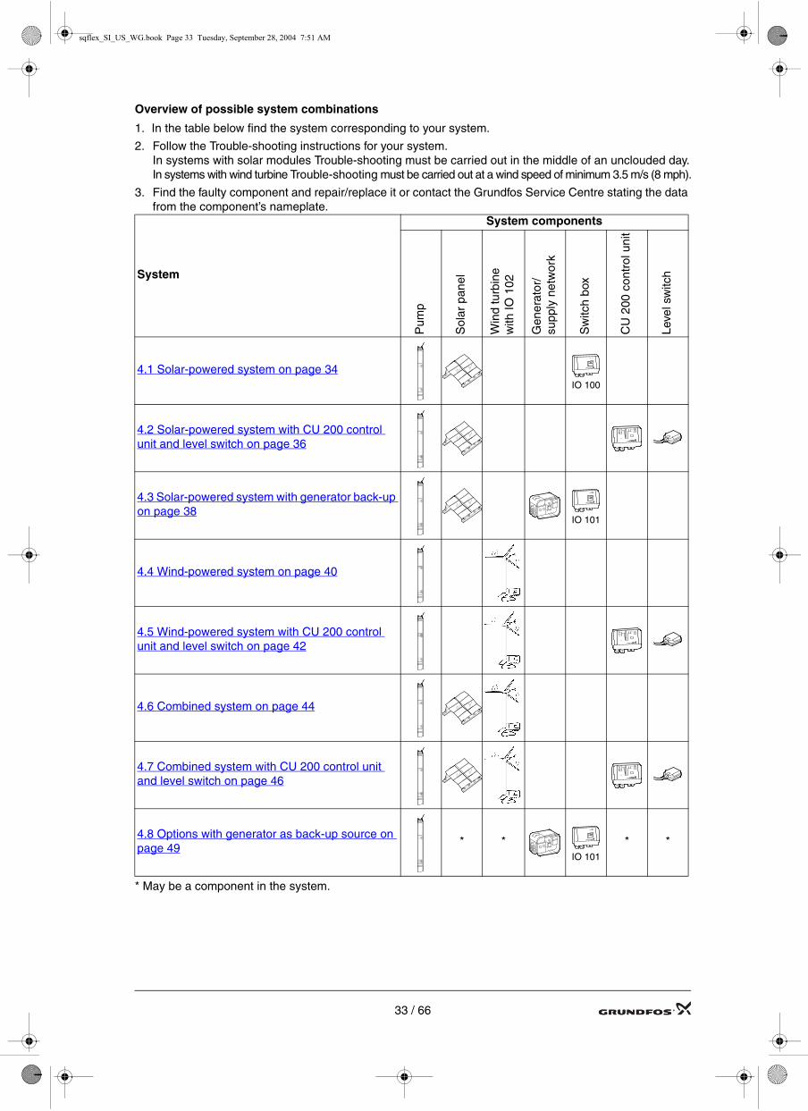
Overview of possible system combinations
1. In the table below find the system corresponding to your system.
2. Follow the Trouble-shooting instructions for your system.In systems with solar modules Trouble-shooting must be carried out in the middle of an unclouded day.In systems with wind turbine Trouble-shooting must be carried out at a wind speed of minimum 3.5 m/s (8 mph).
3. Find the faulty component and repair/replace it or contact the Grundfos Service Centre stating the data from the component’s nameplate.
* May be a component in the system.
System
System components
Pum
p
Sol
ar p
anel
Win
d tu
rbin
e w
ith IO
102
Gen
erat
or/
supp
ly n
etw
ork
Sw
itch
box
CU
200
con
trol
uni
t
Leve
l sw
itch
4.1 Solar-powered system on page 34IO 100
4.2 Solar-powered system with CU 200 control unit and level switch on page 36
4.3 Solar-powered system with generator back-up on page 38
IO 101
4.4 Wind-powered system on page 40
4.5 Wind-powered system with CU 200 control unit and level switch on page 42
4.6 Combined system on page 44
4.7 Combined system with CU 200 control unit and level switch on page 46
4.8 Options with generator as back-up source on page 49
* *IO 101
* *
33 / 66

sqflex_SI_US_WG.book Page 34 Tuesday, September 28, 2004 7:51 AM
4.1 Solar-powered system
If the system does not work properly, follow the instructions in section 4.1.1 Trouble-shooting of a solar-powered system on page 35.
TM
02 2
304
4101
Pos. Component
1. SQF pump
2. Submersible drop cable
3. Cable clips
4. Straining wire
5. Wire clamps
6. Solar modules
7. Support structure
12. IO 100 SQFlex switch box
Fig. 6. Solar-powered system and its main components
TM
02 4
372
4302
Fig. 7. Internal (and external) wiring of IO 100 SQFlex switch box.
2
3
4
5
1
6
7
12
5
2T1
IO 100
4T2 6T3 8T4
Solar modules
34 / 66

sqflex_SI_US_WG.book Page 35 Tuesday, September 28, 2004 7:51 AM
4.1.1 Trouble-shooting of a solar-powered system
1. Disconnect the pump
• Set the IO 100 switch to off.
• Disconnect the pump cable from the terminals (6T3, N, 8T4).
2. Check the solar modules
• Measure the voltage and short-circuit current across the terminals (2T1, 4T2).See electrical connection:
1.4.1 GF 43, GF 50 solar modules on page 141.4.2 SX-110 solar modules on page 161.4.3 FS-50-D solar modules on page 181.4.4 GF 55C and GF 65C solar modules on page 201.4.5 GTF 55 on page 22
If the DC voltage or DC current is outside the range, one or more of the solar modules is faulty. Replace the faulty solar module/s.
3. Check the IO 100 box
• Set the IO 100 switch to on.
• Measure the DC voltage across the terminals (6T3, N, 8T4) using a voltmeter.
• Measure the DC current across the terminals (6T3, N, 8T4) using an ammeter.If the values differ from the values measured under step 2, the IO 100 is defective. Replace the IO 100 box.
4. Check the pump
• Set the IO 100 switch to Off.
• Reconnect the pump cable to the terminals (6T3, N, 8T4).
• Switch on the pump by setting the IO 100 switch to On.Note that the dry running sensor is covered with water.If the pump starts, it was stopped due to dry running and has now been reset.
• Wait five minutes.If the pump does not start, it is defective. Repair or replace the pump.
35 / 66

sqflex_SI_US_WG.book Page 36 Tuesday, September 28, 2004 7:51 AM
4.2 Solar-powered system with CU 200 control unit and level switch
If the system does not work properly, follow the instructions in section 4.2.1 Trouble-shooting of a solar-powered system with CU 200 control unit and level switch on page 37.
Pos. Component
1. SQF pump
2. Submersible drop cable
3. Cable clips
4. Straining wire
5. Wire clamps
6. Solar modules
7. Support structure
11. CU 200 control unit
14. Water reservoir
15. Level switch (optional)
TM
02 2
305
4101
Fig. 8. Solar-powered system with CU 200 and level switch
TM
02 4
371
0702
Fig. 9. Internal (and external) wiring of CU 200 SQFlex control unit
2
3
4
5
1
6
7
11
14
5
15
J1 J2J5
CU 200 Contact closed:Tank full.
Contact open:Tank below level.
Solar modules
36 / 66

sqflex_SI_US_WG.book Page 37 Tuesday, September 28, 2004 7:51 AM
4.2.1 Trouble-shooting of a solar-powered system with CU 200 control unit and level switch
All measuring points/terminal designations in the following refer to the CU 200 control unit.
1. Check the system by means of the CU 200If the CU 200 indicates fault, proceed according to section Trouble-shooting by means of CU 200 on
page 8.
2. Disconnect the pump
• Switch off the pump by pressing the ON/OFF button at the CU 200. The OFF light must be on.
• Disconnect the pump cable from the terminal J2.
3. Check the solar modules
• Measure the voltage and short-circuit current across the terminals (2T1, 4T2).See electrical connection:
1.4.1 GF 43, GF 50 solar modules on page 141.4.2 SX-110 solar modules on page 161.4.3 FS-50-D solar modules on page 181.4.4 GF 55C and GF 65C solar modules on page 201.4.5 GTF 55 on page 22
If the DC voltage or DC current is outside the range, one or more of the solar modules is faulty. Replace the faulty solar module/s.
4. Check the level switch in the water reservoir
• Disconnect the level switch cable from the terminal J5.
• Measure the disconnected level switch cable with an ohmmeter.
• Turn the level switch upwards => the contact in the level switch is closed. The measured value must be approx. 0 Ω.
• Turn the level switch downwards => the contact in the level switch is open. The measured value must be ∞ Ω.If one of the two values is not correct, the level switch is defective. Replace the level switch.
5. Check the CU 200 control unit
• Let the level switch remain disconnected.
• Measure the voltage and current across the terminals for the pump (J2).If the values measured differ from the values measured under step 3, the CU 200 is defective. Replace the CU 200.
6. Check the pump
• Make sure that CU 200 is set to off by pressing ON/OFF button. The OFF light must be on.
• Reconnect the pump cable to the terminal J2.
• Reconnect lewel switch to J5.the lewel switch must point downwards to send a starting signal to the CU 200.
• Switch on the pump by pressing the ON/OFF button. The on light must be on.Note that the dry running sensor is covered with water.If the pump starts, it was stopped due to dry running and has now been reset.
• Wait five minutes.If the pump does not start, it is defective. Repair or replace the pump.
37 / 66

sqflex_SI_US_WG.book Page 38 Tuesday, September 28, 2004 7:51 AM
4.3 Solar-powered system with generator back-up
If the system does not work properly, follow the instructions in section 4.3.1 Trouble-shooting of a solar-powered system with generator back-up.
Pos. Component
1 SQF pump
2 Submersible drop cable
3 Cable clips
4 Straining wire
5 Wire clamps
6 Solar modules
7 Support structure
10 Diesel or petrol powered generator
13 IO 101 switch box
TM
02 2
309
4101
Fig. 10. Solar-powered system with IO 101 and generator
TM
02 4
373
0702
Fig. 11. Internal (and external) wiring of IO 101 SQFlex switch box
2
3
4
5
1
67
13
5
10
IO 101
L
X1.3X1.4
N2T1
4T2
Solar modules
Generator
38 / 66

sqflex_SI_US_WG.book Page 39 Tuesday, September 28, 2004 7:51 AM
4.3.1 Trouble-shooting of a solar-powered system with generator back-up
All measuring points/terminal designations in the following refer to the IO 101 switch box1. Disconnect the pump
• Make sure that the generator has been turned off.
• Set the IO 101 switch to Off.
• Disconnect the pump cable from the terminals (X1.3, X1.4).
2. Check the solar modules
• Measure the DC voltage and short-circuit DC current across the terminals (2T1, 4T2).See electrical connection:
1.4.1 GF 43, GF 50 solar modules on page 141.4.2 SX-110 solar modules on page 161.4.3 FS-50-D solar modules on page 181.4.4 GF 55C and GF 65C solar modules on page 201.4.5 GTF 55 on page 22
If the DC voltage or DC current is outside the range, one of the solar modules is faulty. Replace thesolar module.
3. Check the IO 101 box
• Set the IO 101 switch to on.
• Measure the DC voltage and DC current across the terminals (X1.3, X1.4).If the values differ from the values measured under step 2, the IO 101 is defective. Replace the IO 101.
4. Check the generator
• Set the IO 101 switch to off.
• Turn on the generator.
• Measure the AC voltage across the terminals (L, N).The voltage (U) = rated generator voltage (see generator nameplate).If the value is not correct, the generator is faulty. Repair or replace the generator.
5. Check the IO 101 box during generator operation
• The generator must be running. Set the IO 101 switch to on.
• Measure the AC voltage across the terminals (X1.3, X1.4).The voltage (U) = rated generator voltage (see generator nameplate).If the value is not correct, the IO 101 is faulty. Replace the IO 101.
6. Check the pump
• Set the IO 101 switch to off.
• Reconnect the pump cable to the terminals (X1.3, X1.4).
• Set the IO 101 switch to on.Note that the dry running sensor is covered with water.If the pump starts, it was stopped due to dry running and has now been reset.
• Wait five minutes.If the pump does not start, it is defective. Repair or replace the pump.
39 / 66

sqflex_SI_US_WG.book Page 40 Tuesday, September 28, 2004 7:51 AM
4.4 Wind-powered system
If the system does not work properly, follow the instructions in section 4.4.1 Trouble-shooting of a wind-powered system on page 41.
Pos. Component
1. SQF pump
2. Submersible drop cable
3. Cable clips
4. Straining wire
5. Wire clamps
8. Wind turbine
9. IO 102 breaker box
TM
02 2
306
4101
Fig. 12. The wind-powered system main components.
TM
02 4
374
0702
Fig. 13. Internal (and external) wiring of IO 102 SQFlex breaker box
2
3
4
5
1
8
5
9
IO 102
40 / 66

sqflex_SI_US_WG.book Page 41 Tuesday, September 28, 2004 7:51 AM
4.4.1 Trouble-shooting of a wind-powered system
All measuring points/terminal designations in the following refer to the IO 102 breaker box.1. Disconnect the pump
• Stop the wind turbine and turn off the pump, by turning the ON/OFF switch to off.
• Disconnect the pump cable from the terminals in the IO 102 breaker box.
• Release the wind turbine by turning the ON/OFF switch to on.
2. Check the wind turbine
• Measure the AC voltage across the terminals for the wind turbine, i.e. one measurement between each of the three phases.The voltage (U) = 0-250 VAC. The voltage depends on the wind speed, see Wind turbine on page 24.The three values measured must be identical. If they differ, or if no voltage is measured and the pro-peller is turning, the wind turbine is faulty. Repair or replace the wind turbine.
3. Check the IO 102 breaker box
• Measure the DC voltage across the terminals for the pump.The voltage (U) = 0-300 VDC. The voltage depends on the wind speed, see Wind turbine on page 24.If no voltage is measured and the Propeller is turning, the breaker box is faulty. Replace the breaker box.
4. Check the pump
• Stop the wind turbine by turning the ON/OFF switch to off.
• Reconnect the pump cable to the terminals.
• Release the wind turbine and turn on the pump, by turning the ON/OFF switch to on.Note that the dry running sensor is covered with water.If the pump starts, it was stopped due to dry running and has now been reset.
• Wait five minutes.If the pump does not start, it is defective. Repair or replace the pump.
41 / 66

sqflex_SI_US_WG.book Page 42 Tuesday, September 28, 2004 7:51 AM
4.5 Wind-powered system with CU 200 control unit and level switch
If the system does not work properly, follow the instructions in section 4.5.1 Trouble-shooting of a wind-powered system with CU 200 control unit and level switch on page 43.
Pos. Component
1. SQF pump
2. Submersible drop cable
3. Cable clips
4. Straining wire
5. Wire clamps
8. Wind turbine
9. IO 102 breaker box
11. CU 200 control unit
14. Water reservoir
15. Level switch
TM
02 2
308
4101
Fig. 14. Wind-powered system with CU 200 and level switch
TM
02 4
377
0702
Fig. 15. Internal (and external) wiring of IO 102 breaker box and CU 200 SQFlex control unit
2
3
4
5
1
14
5
15
8
11
9
J1 J2J5
CU 200IO 102 Contact closed:Tank full.
Contact open:Tank below level.
42 / 66

sqflex_SI_US_WG.book Page 43 Tuesday, September 28, 2004 7:51 AM
4.5.1 Trouble-shooting of a wind-powered system with CU 200 control unit and level switch
1. Check the system by means of the CU 200If the CU 200 indicates fault, proceed according to section Trouble-shooting by means of CU 200 on page 8.
2. Disconnect the pump
• Switch off the pump by pressing the ON/OFF button at the CU 200. The OFF light must be on.
• Disconnect the pump cable from the terminal J2.
3. Check the wind turbine
• Measure the AC voltage across the terminals for the wind turbine, i.e. one measurement between each of the three phases.U = 0-250 VAC. The voltage depends on the wind speed, see Wind turbine on page 24.The three values measured must be identical. If they differ, or if no AC voltage is measured and the Propeller is turning, the wind turbine is faulty. Repair or replace the wind turbine.
4. Check the IO 102 breaker box
• Measure the DC voltage across the terminals for the CU 200 in the breaker box.U = 0-300 VDC. The voltage depends on the wind speed, see Wind turbine on page 24.If no DC voltage is measured and the Propeller is turning, the breaker box is faulty. Replace the breaker box.
5. Check the level switch in the water reservoir
• Disconnect the level switch cable from the terminal J5 in CU 200.
• Measure the disconnected level switch cable with an ohmmeter.
• Turn the level switch upwards => the contact in the level switch is closed. The measured value must be approx. 0 Ω.
• Turn the level switch downwards => the contact in the level switch is open. The measured value must be ∞ Ω.If one of the two values is not correct, the level switch is defective. Replace the level switch.
6. Check the CU 200 control unit
• Let the level switch remain disconnected.
• Measure the DC voltage across the terminal for the pump (J2) in CU 200.The value must correspond to the value measured under step 4.If the value differs, the CU 200 is defective. Replace the CU 200.
7. Check the pump
• Make sure that CU 200 is set to off by pressing ON/OFF button. The OFF light must be on.
• Reconnect the pump cable to the terminal J2.
• Connect the level switch cable to the terminal J5.The level switch must point downwards to send a starting signal to the CU 200.
• Switch on the pump by pressing the ON/OFF button. The on light must be on.Note that the dry running sensor is covered with water.If the pump starts, it was stopped due to dry running and has now been reset.
• Wait five minutes.If the pump does not start, it is defective. Repair or replace the pump.
43 / 66

sqflex_SI_US_WG.book Page 44 Tuesday, September 28, 2004 7:51 AM
4.6 Combined system
If the SQFlex system does not work properly, follow the instructions in section 4.5.1 Trouble-shooting of a wind-powered system with CU 200 control unit and level switch on page 43.
Pos. Component
1. SQF pump
2. Submersible drop cable
3. Cable clips
4. Straining wire
5. Wire clamps
6. Solar modules
7. Support structure
8. Wind turbine
9. IO 102 breaker box
TM
02 2
307
4101
Fig. 16. Combined system main components
TM
02 4
375
0702
Fig. 17. Internal (and external) wiring of IO 102 SQFlex breaker box
2
3
4
5
1
5
9
7
6
8
IO 102Solar modules
44 / 66
sqflex_SI_US_WG.book Page 45 Tuesday, September 28, 2004 7:51 AM
4.6.1 Trouble-shooting of a combined system
All measuring points/terminal designations in the following refer to the IO 102 breaker box.1. Disconnect the pump
• Set the IO 102 switch to off.
• Disconnect the pump cable from the terminals.
• Disconnect plus or minus from the solar modules. WARNING: Do not touch the wire due to high voltage.Release the wind turbine by setting the IO 102 switch to on.
2. Check the wind turbine
• Measure the AC voltage across the terminals for the wind turbine, i.e. one measurement between each of the three phases.U = 0-250 VAC. The voltage depends on the wind speed, see Wind turbine on page 24.The three values measured must be identical. If they differ (more than 10 V), or if no voltage is measured and the wind turbine is turning, the wind turbine is faulty. Repair or replace the wind tur-bine.
3. Check the IO 102 breaker box with wind turbine connected
• Measure the DC voltage across the terminals for the CU 200 in the breaker box.U = 0-300 VDC. The voltage depends on the wind speed, see Wind turbine on page 24.If no DC voltage is measured and the wind turbine is turning, the breaker box is faulty. Replace the breaker box.
4. Check the solar modules
• Disconnect the three wires from the wind turbine one by one and short-circuit all three wires to each other in order to stop the turbine.WARNING: Do not touch the wire due to high voltage.
• Reconnect the wire from the solar panel which was disconnected under step 1.
• Measure the DC voltage and short-circuit DC current across the terminals (2T1, 4T2).See electrical connection:
1.4.1 GF 43, GF 50 solar modules on page 141.4.2 SX-110 solar modules on page 161.4.3 FS-50-D solar modules on page 181.4.4 GF 55C and GF 65C solar modules on page 201.4.5 GTF 55 on page 22
If the DC voltage or DC current is outside the range, one ore more of the solar modules is faulty. Replace the faulty solar module/s.
5. Check the IO 102 breaker box with solar modules connected
• Connect the solar modules by setting the IO 102 switch to on.
• Measure the DC voltage and short circuit DC current, across the terminals for the pump.The values must correspond to the values measured under step 4.If the values differ, the breaker box is defective. Replace the breaker box.
6. Reset of dry-running alarm
• Set the IO 102 switch to off.
• Reconnect the pump cable to the terminals.
• Set the IO 102 switch to on.Note that the dry running sensor is covered with water.If the pump starts, it was stopped due to dry running and has now been reset.
• Wait five minutes.If the pump does not start, it is defective. Repair or replace the pump.
45 / 66

sqflex_SI_US_WG.book Page 46 Tuesday, September 28, 2004 7:51 AM
4.7 Combined system with CU 200 control unit and level switch
If the system does not work properly, follow the instructions in section 4.7.1 Trouble-shooting of a com-bined system with CU 200 control unit and level switch on page 47.
Pos. Component
1. SQF pump
2. Submersible drop cable
3. Cable clips
4. Straining wire
5. Wire clamps
6. Solar modules
7. Support structure
8. Wind turbine
9. IO 102 breaker box
11. CU 200 control unit
14. Water reservoir
15. Level switchT
M02
231
0 41
01
Fig. 18. Combined system with CU 200 and level switch
TM
02 4
376
0702
Fig. 19. Internal (and external) wiring for IO 102 SQFlex breaker box and CU 200 SQFlex control unit
2
3
4
5
1
14
5
15
7
8
9
6
11
J1 J2J5
CU 200IO 102 Contact closed:Tank full.
Contact open:Tank below level.
46 / 66

sqflex_SI_US_WG.book Page 47 Tuesday, September 28, 2004 7:51 AM
4.7.1 Trouble-shooting of a combined system with CU 200 control unit and level switch
Measuring points/terminal designations in the following refer to the IO 102 breaker box or the CU 200.1. Disconnect the pump
• Set the IO 102 switch to off.
• Disconnect plus or minus from the solar modules.WARNING: Do not touch the wire due to high voltage.
• Disconnect the pump cable from the terminal J2.
• Release the wind turbine by setting the IO 102 switch to on.
2. Check the wind turbine
• Measure the AC voltage across the terminals for the wind turbine, i.e. one measurement between each of the three phases.U = 0-250 VAC. The voltage depends on the wind speed, see Wind turbine on page 24.The three values measured must be identical. If they differ, or if no voltage is measured and the wind turbine is turning, the wind turbine is faulty. Repair or replace the wind turbine.
3. Check the IO 102 breaker box with wind turbine connected
• Measure the DC voltage across the terminals for the CU 200 in the breaker box.U = 0-300 VDC. The voltage depends on the wind speed, see Wind turbine on page 24.If no voltage is measured and the wind turbine is turning, the breaker box is faulty. Replace the breaker box.
4. Check the solar modules
• Disconnect the three wires from the wind turbine one by one and short-circuit all three wires to each other in order to stop the turbine.WARNING: Do not touch the wire due to high voltage.
• Reconnect the wire from the solar panel which was disconnected under step 1.
• Measure the DC voltage and short-circuit DC current across the terminals (2T1, 4T2).See electrical connection:
1.4.1 GF 43, GF 50 solar modules on page 141.4.2 SX-110 solar modules on page 161.4.3 FS-50-D solar modules on page 181.4.4 GF 55C and GF 65C solar modules on page 201.4.5 GTF 55 on page 22
If the DC voltage or DC current is outside the range, one or more of the solar modules is faulty. Replace the faulty solar module/s.
5. Check the IO 102 breaker box with solar modules
• Connect the solar modules by setting the IO 102 switch to on.
• Measure the DC voltage and short circuit DC current, across the terminals for the pump.The values must correspond to the values measured under step 4.If the values differ, the breaker box is defective. Replace the breaker box.
6. Check level switch in the water reservoir
• Release the wind turbine by setting the IO 102 switch to on.
• Disconnect the level switch cable from the terminal J5.
• Measure the disconnected level switch cable with an ohmmeter.
• Turn the level switch upwards => the contact in the level switch is closed. The measured value must be approx. 0 Ω.
• Turn the level switch downwards => the contact in the level switch is open. The measured value must be ∞ Ω.If one of the two values is not correct, the level switch is defective. Replace the level switch.
7. Check the CU 200 control unit
• Let the level switch remain disconnected.
• Measure the DC voltage across the terminals for the pump (J2).The value must correspond to the value measured under step 3 or 5.Note: The sun and wind conditions may have changed since the measurements in point 3 or 5 were madeIf the value differs, the CU 200 is defective. Replace the CU 200.
47 / 66
sqflex_SI_US_WG.book Page 48 Tuesday, September 28, 2004 7:51 AM
8. Check the pump
• Make sure that CU 200 is set to off by pressing ON/OFF button. The OFF light must be on.
• Reconnect the pump cable to the terminal J2.
• Connect the level switch cable to the terminal J5.The level switch must point downwards to send a starting signal to the CU 200.
• Press the ON/OFF button the on light must be on.Note that the dry running sensor is covered with water.If the pump starts, it was stopped due to dry running and has now been reset.
• Wait five minutes.If the pump does not start, it is defective. Repair or replace the pump.
48 / 66

sqflex_SI_US_WG.book Page 49 Tuesday, September 28, 2004 7:51 AM
4.8 Options with generator as back-up sourceBelow are wiring diagrams for options with generator as a power supply back-up source.
For Trouble-shooting of the individual components see sections 3.1 to 3.7.For application overview see section Overview of possible system combinations on page 33.
Solar-powered system with CU 200 control unit and level switch
Wind-powered system
Wind-powered system with CU 200 control unit and level switch
IO 101
L
X1.3X1.4
N 2T14T2
J1 J2J5
CU 200
IO 102 IO 101
L
X1.3X1.4N 2T1
4T2
IO 102 IO 101
L
X1.3X1.4N 2T1
4T2J1 J2
J5
CU 200
49 / 66

sqflex_SI_US_WG.book Page 50 Tuesday, September 28, 2004 7:51 AM
Combined system
Combined system with CU 200 control unit and level switch
IO 102 IO 101
L
X1.3X1.4N 2T1
4T2
IO 102 IO 101
LX1.3
X1.4N 2T14T2
J1 J2J5
CU 200
50 / 66

sqflex_SI_US_WG.book Page 51 Tuesday, September 28, 2004 7:51 AM
5. Service of pump and motor
5.1 General informationHelical rotor pumps cannot be separated from the motor as a unit. If the motor or the pump has to be re-placed, the pump must be dismantled, see section 5.4 Helical pump type on page 55.
Position numbers refer to exploded views, sectional drawings and parts lists; tool letters refer to section 5.2 Service tools on page 52.
5.1.1 Before dismantling
• Disconnect the electricity supply to the motor.
5.1.2 Before assembly
• Clean all parts and check them for fractures and wear.
• Order the necessary service kits and/or parts.
• Replace defective parts by new parts.
• Moisten rubber parts with soapy water before fitting them.
5.1.3 During assembly
• Lubricate and/or tighten screws and rubber parts according to section 5.3 Torques and lubricants on page 54.
• Before connecting the pump to the motor, fill the motor with GRUNDFOS motor liquid SML 2.
Filling of motor liquid
5.1.4 After assembly
• Test the head and flow according to the test specifications, see section 5.9 Testing the pump by means of CU 200 SQFlex control unit on page 60.
TM
02 5
769
3902
Fig. 20. When fixing the motor in a vice, tighten only on the 30 mm wide area starting 37 mm from the upper edge of the motor sleeve.
1. Place the motor in vertical position with an inclination of approx. 10°.
2. Remove the filling plug using a screwdriver or a similar tool.
3. Inject motor liquid SML 2, into the motor with a filling syringe or the like.
4. To allow possible air to escape, move the motor from side to side.
5. Refit the filling plug and make sure that it is tight.
Fit the pump to the motor, see section 5.5.2 Fitting pump to motor on page 56 (centrifugal pump) or section 5.4.2 Assembly on page 55 (helical pumps)
TM
01 1
434
4597
Fig. 21. Filling of motor
3730
10
51 / 66
sqflex_SI_US_WG.book Page 52 Tuesday, September 28, 2004 7:51 AM
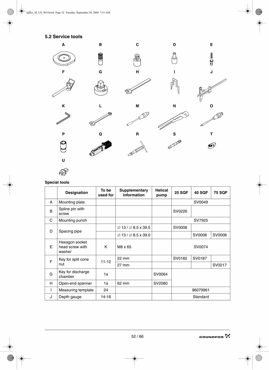
5.2 Service tools
Special tools
A B C D E
F G H I J
K L M N O
P Q R S T
U
DesignationTo be
used forSupplementary
informationHelical pump
25 SQF 40 SQF 75 SQF
A Mounting plate SV0049
BSpline pin with screw
SV0226
C Mounting punch SV7925
D Spacing pipe13 / 8.5 x 39.5 SV0006
13 / 8.5 x 39.0 SV0008 SV0008
EHexagon socket head screw with washer
K M8 x 65 SV0074
FKey for split cone nut
11-1222 mm SV0182 SV0187
27 mm SV0217
GKey for discharge chamber
1a SV0064
H Open-end spanner 1a 62 mm SV2080
I Measuring template 24 96079961
J Depth gauge 14-16 Standard
∅ ∅
∅ ∅
52 / 66

sqflex_SI_US_WG.book Page 53 Tuesday, September 28, 2004 7:51 AM
Standard tools
Torque tools
Pos. DesignationTo be
used forSupplementary
informationHelical pump
25 SQF 40 SQF 75 SQF
K Hexagon key E 6 mm SV1204
LRing/open-end spanner
16-2410 mm (two pcs. needed for pos.16)
SV0083
19-19a 13 mm SV0055
MNut driver with socket
250 7 mm SV0065
N Pipe wrench13 1" standard
14a 4" standard
O Screwdriver (torx) 18a T10 SV0066
PSocket for hexagon head screws
250-S 7 mm 1/4" SV0457
Pos. DesignationTo be
used forSupplementary
informationHelical pump
25 SQF 40 SQF 75 SQF
Q Torque wrenchS-U 4-20 Nm 9x12 SV0292
G 40-200 Nm14x18 SV0400
R Torque screwdriver S 1-6 Nm 1/4" SV0438
SAdapter for torque screwdriver
O-P 1/4" SV0437
T Ring insert tool Q-19-19a 13 mm 9x12 SV0294
U Open-end spanner
F-Q-11-12
22 mm 9x12 SV0622
Q-16 10 mm 9x12 SV0610
53 / 66

sqflex_SI_US_WG.book Page 54 Tuesday, September 28, 2004 7:51 AM
5.3 Torques and lubricantsThis section shows the screws and nuts that must be tightened to a certain torque and the lubricants to be used.
Rocol Sapphire Aqua-Sil, part no. RM2924 (0.5 l).
Gardolube L 6034, part no. SV9995 (1 l).
It is not necessary to lubricate screws and nuts treated with "Delta Seal", as this coat is anti-corrosive and lubricating.
* The thread of the discharge chamber must be lubricated.
Pos. Description Pump type Torque [Nm] Lubricant
Pump / motor Helical 55
1a Discharge chamber* Helical 100 Rocol
13/16 Pump rotor / torsion shaft Helical 18
14a Connecting piece Centrifugal
16 Torsion shaft / motor shaft Helical 18
19Screw Centrifugal, splined shaft
18 GardolubeNut Centrifugal, cylindrical shaft
19a Nut Centrifugal 18 Gardolube
19b Nut Centrifugal, splined shaft 11 Gardolube
24 Shaft end (nut) Centrifugal 18
End cover with cable All Rocol
Nut All 1,5
54 / 66

sqflex_SI_US_WG.book Page 55 Tuesday, September 28, 2004 7:51 AM
5.4 Helical pump typeHelical pumps cannot be separated from the motor as a unit. If the motor or the pump must be replaced, the pump must be dismantled.
5.4.1 Dismantling
1. Fix the motor in a vice.Note: Tighten only on the area shown in fig. 20.
2. Unscrew the screws pos. 18a and 18b and remove them together with the cable guard pos. 18.
3. If the motor is intact, the cable need not to be removed. If the motor is defective, remove the nuts for end cover with socket at the bottom of the motor and pull the end cover with cable and socket out of the motor.
4. Remove the discharge chamber pos. 1a with valve casing complete using the key for discharge cham-ber G. Hold the pump by means of the pipe wrench N on the weld just above the upper strainer.
5. Loosen the outer sleeve pos. 55 with pump stator pos. 9 from the motor using the pipe wrench N on the weld just above the upper strainer. Hold the motor with the open-end spanner H.
6. Pull the outer sleeve pos. 55 with pump stator pos. 9 free of the pump rotor pos. 13 and torsion shaft pos. 16 with a bump.
7. Remove the pump stator pos. 9 and flange pos. 6 by knocking the discharge end of the outer sleeve hard against a solid wooden surface such as a workbench or table.
8. Remove the torsion shaft pos. 16 from the motor shaft using two ring/open-end spanners L.
9. Remove the pump rotor pos. 13 from the torsion shaft pos. 16 using the pipe wrench N. Hold the torsion shaft with the ring/open-end spanner L.
10. If the parts of the valve casing complete are defective, replace these parts. Prise the retaining ring pos. 7a out of the recess of the discharge chamber pos. 1a and press the parts down and out of the dis-charge chamber.
5.4.2 Assembly
1. Fill the motor with liquid, see Filling of motor liquid on page 51
2. Fit the pump rotor pos. 13 to the torsion shaft pos. 16 and tighten to correct torque, see 5.3. Hold the pump rotor using the pipe wrench N on the cylindrical part below the pump rotor.
3. Fit the torsion shaft to the motor shaft and tighten to the correct torque, see 5.3.
4. Fit the pump stator pos. 9 with the conical stator inlet against the strainer into the outer sleeve pos. 55 .
5. Fit the flange pos. 6 into the outer sleeve and press it on the upper part of the stator, fixing the stator in the centre of the outer sleeve.
11SQF-2: Turn the flange pos. 6 with the even surface against the stator pos. 9.
6. Assemble the valve and discharge chamber if it has been dismantled.
• Place the valve casing complete on a plane surface with the bearing pos. 6 downwards.
• Lubricate the O-ring pos. 1d with grease and fit it in the outside recess of the valve casing.
• Press the discharge chamber pos. 1a over the valve casing. Turn the discharge chamber and fit the retaining ring pos. 7a in the recess of the discharge chamber.
• Grease the thread of the discharge chamber with valve casing complete and screw it into the top of the sleeve.
7. Fit the discharge chamber pos. 1a with valve casing complete and tighten to the correct torque by means of the key for discharge chamber G. Hold the pump using the pipe wrench N or fix it in a vice. The jaws must be placed on the weld just above the upper strainer.
8. Moisten the pump rotor pos. 13 with clean water and fit the pump on the motor. Tighten to the correct torque, see 5.3 by means of the key for discharge chamber G.
9. Push the end cover with socket and cable into the motor if it has been removed. Fit and tighten the nuts using the socket for hexagon head screws P, the adapter for torque screwdriver S and the torque screwdriver R.
10.Fit the cable guard pos. 18. Press the two upper flaps under the outer sleeve and fit the screws pos. 18a and 18b. If the accessible holes in the outer sleeve at the lower strainer are not threaded, they must be tapped using the tapping screw included in the cable guard service kit and the assembly kit or by means of an M3 set screw.
11.Test the pump performance using a CU 200 control unit, if available. See section 5.9 Testing the pump by means of CU 200 SQFlex control unit on page 60
12. Install the pump. See section 2. Start-up on page 28.
55 / 66

sqflex_SI_US_WG.book Page 56 Tuesday, September 28, 2004 7:51 AM
5.5 Centrifugal pump and motor
5.5.1 Detaching pump from motor
1. Fix the motor in a vice.Note: Tighten only on the area shown in fig. 20.
2. Unscrew the screws pos. 18a and remove them together with the cable guard pos. 18c.
3. Unscrew the screws pos. 18b and remove them (if any) together with the cable guard pos. 18.
4. If the motor is intact, the cable need not be removed. If the motor is defective, remove the nuts for the end cover with socket and pull the end cover with cable and socket out of the motor.
5. Remove the nuts pos. 19a and lift the pump off the motor
6. Remove the spline protector pos. 24b and supporting ring pos. 24a from the pump shaft.
7. Remove the shaft end pos. 24 from the motor shaft.
8. Remove the connecting piece pos. 14a from the motor by means of the pipe wrench N. Hold the motor using the open-end spanner H.
5.5.2 Fitting pump to motor1. Fill the motor with liquid, see Filling of motor liquid on page 51.
2. Screw the shaft end pos. 24 on to the motor shaft and push it home. Adjust the height to 88.15 mm ±0.2 mm by means of the measuring template I, see fig. 22.
3. Tighten the nut to the correct torque, see 5.3. Check that the height is still 88.15 mm ±0.2 mm.
4. Fit the supporting ring pos. 24a and the spline protector pos. 24b.
5. Fit the connecting piece pos. 14a and tighten using the pipe wrench N.
TM
02 5
770
3902
Fig. 22.
6. Fit the pump to the motor. The cable recesses in the suction interconnector pos. 14 and the connecting piece pos. 14a must be next to each other. Fit the four nuts pos. 19a and tighten diagonally to the cor-rect torque, see 5.3.
7. Push the end cover with cable into the motor if it has been removed. Fit and tighten the nuts, see 5.3 using the socket for hexagon head screws P, the adapter for torque screwdriver S and the torque screwdriver R.
8. Fit the cable guard pos. 18c and secure it with screws pos. 18a.
9. Fit the cable guard pos. 18 and secure with screws pos. 18b ( 25 SQF).
10.Test the pump performance using a CU 200 control unit, if available. See section 5.9 Testing the pump by means of CU 200 SQFlex control unit on page 60.
11. Install the pump, see section 2. Start-up on page 28.
56 / 66

sqflex_SI_US_WG.book Page 57 Tuesday, September 28, 2004 7:51 AM
5.6 Centrifugal pump type with splined shaft
5.6.1 Dismantling
1. Fit the and tighten the spline pin with screw B on the mounting plate A.Note: Make sure that the mounting plate is positioned correctly so that the recess of the mounting plate and the suction interconnector pos. 14 fit into each other.
2. Place the pump on the mounting plate A.
3. Unscrew and remove the screws pos. 19 together with the washers pos. 71. Remove the strap pos. 17.
4. Dismantle the pump in the following order until the last chamber has been removed:
• discharge piece pos. 1b
• valve casing complete pos. 1
• nut pos. 19b
• washer pos. 76
• impeller pos. 13
• chamber pos. 9.
5. Pull the pump shaft pos. 16 with priming disc pos. 64 up and out of the suction interconnector pos. 14 and the bottom chamber pos. 10.
6. Lift the suction interconnector pos. 14 and the bottom chamber pos. 10 free of the mounting plate A.
7. Replace worn wear parts, if any, see section 5.8 Checking and replacing wear parts of centrifugal pumps on page 59
5.6.2 Assembly
1. Fit the suction interconnector pos. 14 to the mounting plate A.
2. Press the bottom chamber pos. 10 into the suction interconnector pos. 14.
3. Slide the priming disc pos. 64 over the pump shaft pos. 16 and push until it touches the coupling.Note: The dogs of the priming disc must point upwards.
4. Fit the pump shaft to the spline pin with screw B.
5. Fit the first impeller pos. 13 and press it until it engages with the neck ring pos. 7 in the bottom chamber pos. 10.
6. Fit the chamber pos. 9 and the impeller pos. 13 until the last impeller has been fitted.
7. Fit the washer pos. 76 (with the three grooves upwards) and the nut pos. 19b.
8. Make sure that the top impeller engages with the splined shaft and tighten the nut pos. 19b to the cor-rect torque, see 5.3.Note: Check that the impellers can be raised and lowered, as it is important that the nut is tightened against the impellers.
9. Fit the valve casing complete pos. 1 and the discharge piece pos. 1b.Note: Turn the discharge piece so that the slots for the cable guard are located above the screw holes for the screws pos. 18b in the suction interconnector pos. 14.
10.Lubricate the threads of the screws pos. 19, and fit the straps pos. 17, washers pos. 71 and screws pos. 19. Tighten diagonally to the correct torque, see 5.3.
11.Remove the pump from the mounting plate A and fit the pump to the motor, see section 5.5.2 Fitting pump to motor on page 56.
57 / 66

sqflex_SI_US_WG.book Page 58 Tuesday, September 28, 2004 7:51 AM
5.7 Centrifugal pump type with cylindrical shaft
5.7.1 Dismantling
1. Fit the mounting plate A to the suction interconnector pos. 14 by means of the spacing pipe D and the hexagon socket head screw with washer E.Note: Make sure that the mounting plate is positioned correctly so that the recess of the mounting plate and the projection of the suction interconnector pos. 14 fit into each other.Fix the mounting plate in a vice.
2. Slacken and remove the nuts pos. 19. Remove the strap pos. 17.
3. Remove the valve housing complete pos. 1 and the top chamber pos. 4 (25 SQF N chamber pos. 9.)Remove the stop ring pos. 85 of 25 SQF N.
4. Loosen the split cone nut pos. 11 using the key for split cone nut F. Knock the split cone pos. 12 down through and out of the impeller pos. 13 using the key for split cone nut F.
5. Remove the impeller pos. 13, split cone pos. 12, split cone nut pos. 11 and chamber pos. 9.
6. Repeat steps 4. and 5. until all impellers and chambers have been removed. Remove the stop ring pos. 85 of 75 SQF.
7. Loosen the guide pos. 25 from the recess of the suction interconnector pos. 14 (only 75 SQF). Lift the suction interconnector off the mounting plate A.
8. Remove the hexagon socket head screw with washer E, spacing pipe D and pump shaft pos. 16.
9. Check and replace wear parts, see section 5.8 Checking and replacing wear parts of centrifugal pumps on page 59.
5.7.2 Assembly
1. Fit the shaft pos. 16 to the mounting plate A by means of the spacing pipe D and hexagon socket head screw with washer E.Note: Make sure that the mounting plate is positioned correctly so that the recess of the mounting plate and the projection of the suction interconnector pos. 14 fit into each other.Fix the mounting plate in a vice.
2. Slide the suction interconnector pos. 14 over the shaft so that the projection of the suction interconnec-tor engages with the recess of the mounting plate. Press the bottom chamber pos. 10 / guide pos. 25 home in the suction interconnector.
3. Fit the split cone pos. 12, impeller pos. 13 (the impeller collar must point downwards) and split cone nut pos. 11. Give the split cone nut a few turns. Press the impeller home against the chamber pos. 10 / guide pos. 25 using the key for split cone nut F and tighten to the correct torque, see 5.3.
4. Fit the chamber pos. 9.
5. Repeat steps 3. and 4. until all impellers and chambers have been fitted.Note: For each section, make sure that the chamber and the impeller are fitted correctly before the split cone nut is tightened.Note: Fit the stop ring pos. 85 after the middle impeller of 25 SQF and 75 SQF. In 75 SQF the small recess of the stop ring must be downwards.Note: The top chamber of 40 SQF and 75 SQF is pos. 4.
6. Fit the valve housing pos. 1 so that the holes for the straining wire are opposite the motor cable (cable opening in the suction interconnector) and that the slots for the straps are aligned to the points where the straps are attached to the suction interconnector.
7. Fit the strap pos. 17 and nuts pos. 19. Tighten diagonally to the correct torque, see 5.3.
8. Remove the pump from the mounting plate A and fit it on the motor, see section 5.5.2 Fitting pump to motor on page 56.
9. Check the axial clearance of the pump shaft by measuring the distance between the contact surface of the suction interconnector and the shaft end using a slide gauge or depth gauge. Measure with the shaft in its top and bottom position, see below.
25 SQF 75 SQF 40 SQF
TM
01 6
247
1999
Bottom position Hmax 37.5 37.15 37.15
Top position Hmin 38.4 39.15 40.15
H
58 / 66

sqflex_SI_US_WG.book Page 59 Tuesday, September 28, 2004 7:51 AM
5.8 Checking and replacing wear parts of centrifugal pumps
Bearing pos. 8
Check Replace
• Check whether the bearings are defective due to sand or dry running.
• Remove the bearing pos. 8 by pressing it out of the chamber pos. 9.
• Press a new bearing into the chamber from the bottom side with the largest bearing diameter against the bottom side of the chamber.
Top bearing pos. 6
Check Replace
• Check whether the bearing is defective. • Press the bearing pos. 6 out of the valve housing (cylindrical shaft).25 SQF (splined shaft): Press the bearing out using a screwdriver, if necessary.
• Press the new bearing into the valve housing from the bottom side.
Valve seat pos. 3 (only in 25 SQF)
Check Replace
• Check whether the rubber is hard or compressed so that the valve cup pos. 2 touches the metal.
• Free the valve guide pos. 70 where it is posi-tioned under the recess of the valve casing. Pull the guide and the valve cup pos. 2 out of the valve housing.
• Push the valve seat pos. 3 out of the valve hous-ing by inserting a screwdriver between the valve seat and the valve housing.
• Press the valve seat home in the valve housing with the flat side downwards.
Neck ring pos. 7
Check Replace
• Check whether the rubber is hard or worn as this may reduce the head or flow rate.
• Prize the neck ring pos. 7 free of the chamber pos. 9/10 or guide pos. 25 by inserting a screw-driver between the neck ring and the chamber/guide.
• Press the neck ring home in the chamber pos. 9/10 or guide pos. 25. The following side of the neck ring must be up:
• 25 SQF smooth surface
• 40 SQF "This side up"
• 75 SQF lip
59 / 66

sqflex_SI_US_WG.book Page 60 Tuesday, September 28, 2004 7:51 AM
5.9 Testing the pump by means of CU 200 SQFlex control unitThe pump must deliver a flow rate (m³/h) at a given power consumption and head. The “Test value curves ‘ on page 61 apply to the head stated for each pump. The curve values are minimum values.
1. Open the discharge valve completely to reduce the counter-pressure to a minimum.
2. Disconnect the power supply to the pump.
3. Remove the front cover of the CU 200, and set the test jumper to service position, see illustration. Refit the front cover.
4. Connect the power supply.
5. Make sure that the system is off. The red indicator light of the ON/OFF button must be on. If the system is not off, press the ON/OFF button once.
6. Press the ON/OFF button for at least four seconds. Release the button. The CU 200 is now in test mode. (The bottom flow indicator is permanently on, and the pump is running slowly.)
7. Press the ON/OFF button twice (the upper flow indicator is permanently on). The pump now adjusts its speed.
8. Adjust the counter-pressure to the value stated for each pump in the curves in section 5.9.1 Test value curves on page 61.
9. Read the flow rate Q [m³/h] using a flowmeter or a similar device and the power consumption P1 [W] using a wattmeter.
10. In the relevant curve chart, find the intersection point of the values read for flow (Q) and power consumption P1 [W].- If the intersection is above the minimum curve, the flow rate is sufficient.- If the intersection is below the minimum curve, the flow rate is insufficient, and the pump should be checked and defective parts replaced.
11.Press the ON/OFF button once. The CU 200 is no longer in test mode.
12.Disconnect the power supply, and disconnect the pump and the CU 200.
13.Move the test jumper from service to normal position.
TM
02 5
908
4002
SERVICE
NORMAL
SERVICE
NORMAL
MAIN
SWITCHHead
H QFlow
ACW
90-240 VAC +6%/-10%50/60 Hz
Test jumper
60 / 66

61 / 61 66
5.9.1 Test value curves
The curve shown in the curve charts below is the minimum performance curve for the pump.
Service test, 3 SQF-2H = 200 ft.
Service test, 6 SQF-2H = 200 ft.
Service test, 11 SQF-2H = 130 ft.
Service test, 25 SQF-3H = 30 ft.
Service test, 25 SQF-6H = 100 ft.
Service test, 40 SQF-3H = 30 ft.
Service test, 75 SQF-3H = 50 ft.
3,00
2,50
2,00
1,50
1,00
00 50 100 150 200 250 300
US
gal
/m
P1 [W]
H 200 ft.
0,50
6
5
4
3
2
00 100 200 300 400 500
US
gal
/m
P1 [W]
1
11
9
7
5
00 100 200 300 400 500
US
gal
/m
P1 [W]
3
600 700
28
24
20
16
12
00 100 200 300 400 500 600
US
gal
/m
P1 [W]
8
4
25
20
15
10
5
00 100 200 300 400 500 600 700 800 900 1000
US
gal
/m
P1 [W]
45
36
27
18
9
00 100 200 300 400 500 600 700 800 900 1000
US
gal
/m
P1 [W]
45
00 100
US
gal
/m
P1 [W]
40
35
30
25
20
15
10
5
200 300 400 500 600 700 800 900 1000
sqflex_SI_US_WG.book Page 61 Tuesday, September 28, 2004 7:51 AM

sqflex_SI_US_WG.book Page 62 Tuesday, September 28, 2004 7:51 AM
Drawings
25 SQF
TM
02
224
7 3
901
13 78
8
7
9
1
70
3
6
2
19b
76
1b
71
19
10
7
16
64
14
13
18b
18a
18
9
7
8
13
17
24
24b
24a
18c
14a
19a
62 / 66
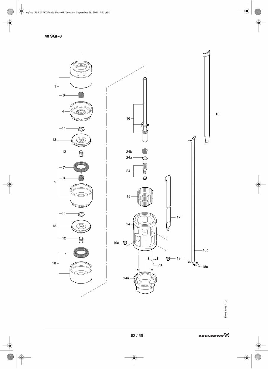
sqflex_SI_US_WG.book Page 63 Tuesday, September 28, 2004 7:51 AM
40 SQF-3
TM
02 4
056
47
01
11
13
12
7
10
6
4
8
1
9
12
13
11
7
24
24b
24a
78
14
17
19
15
18a
18
18c
14a
19a
16
63 / 66

sqflex_SI_US_WG.book Page 64 Tuesday, September 28, 2004 7:51 AM
75 SQF-3
TM
02 2
438
43
01
24
24b24a
78
11
7
6
8
9
14
17
19
15
12
1
13
13
12
9
8
7
11
11
7
12
13
254
85
16
18a
18
18c
14a
19a
64 / 66

sqflex_SI_US_WG.book Page 65 Tuesday, September 28, 2004 7:51 AM
Helical (3 SQF-2, 6 SQF-2, 11 SQF-2)
TM
02 2
216
39
01
18b
18a
1d
7a
1
70
2
39
3
1a
6
9
55
13
16
18
1b
65 / 66

sqflex_SI_US_WG.book Page 66 Tuesday, September 28, 2004 7:51 AM
Windturbine
TM
02 4
386
08
02
10
14
15
17
16
18
6
7
8
9
12
11
13
19
17
16
1
432
5
66 / 66