service information 9 ul 91 - e
TRANSCRIPT
Introduction
This information is intended to assist the aircraft designer and manufacturer to achieve correct operating conditions for the engine and consequently optimum performance and reliability.
ROTAX ultralight engines have been specifically developed for use in ultralight aircraft. They are not intended to be used for certified motorgliders and other aircraft subject to specific legislation. If in doubt, the regulations of the national authorities or governing bodies should be consulted.
The engines must only be run with accessories supplied, recommended or approved by ROTAX. Modifications must not be made without the approval of the engine manufacturer.
For operational limitations please refer to the respective data sheets andinstructions (see paragr. 2).The following installation instructions should help to prevent mistakes and to ensure safe subsequent operation.
Technical data and general information
In addition to these installation instructions please refer to
- Operators’ Manual - Engine Data Sheet - Power, torque and fuel consumption curves - Spare parts list.
Engine installation and mounting points
a 3.1) Position of engine
3.1.1) Standard installation:
Refers to engine with crankshaft in horizontal position and cylinders up (i.e. spark plugs on top). This installation should be applied if any possible.
3.1.2) Inverted engine installation:
If an engine is to be installed with cylinders down (i.e. spark plugs towards bottom), observe the hints in the manual for the respective engine as well as paragraphs 53.6) and 10.3) in this Service Information. Installation with spark plugs down involves certain disadvantages, e.g. as to spark plug life, carbon deposits in combustion chamber and engine lubrication. In case of doubt, contact the engine manufacturer (in writing).
BOMBARDIER - ROTAX GESELLSCHAFT M.B.H. MOTORENFAB~~K
”
A-4623 GUNSKIRCHEN-AUSTRIA Teiefon: 437246-271-O’, T&fax: 43-7246-370 Telex: 26646 brgk a, Telegr.: Bombrotax Gunskirchen

f$J!$RJfHcfJ ~~~f-‘jR~A,THJf-J~
-2-
3.1.3) Installation with crankshaft vertical:
It is only permitted under certain conditions. Please, always contact the engine manufacturer in writing for more information.
3.2) Engine fixation points
3.2.1) There are 4 bosses with Ml0 threads on the bottom of the crankcase.
3.2.2) A ROTAX reduction gearbox is recommended, but if this is not used, there are additional bosses on the p.t.o. end of the engine. These bosses may be used as extra fixation points (in addition to the bottom fixation points, not on their own).
3.2.3) The fixation points on the cylinder head should be taken only after consulting the engine manufacturer (in writing).
3.2.4) It is essential to have rubber anti-vibration mountings between the engine and the fuselage, to limit the transmission of vibrations which could severely damage the airframe and the engine.
4) Propeller drive
4.1) Propeller installation - The propeller must not be fitted directly to the crankshaft. Exemptions require special tests and permission of the engine manufacturer. By all means the instructions of the propeller manufacturer have to be respected,
4.2) Engine speed The engine speed must be reduced to propeller speed. ROTAX has developed special reduction gearboxes for ultralight engines. Usually the gearbox is supplied already fitted to the engine. If the gearbox is supplied separately, please refer to chapter 13 for gearbox installation to engines type 277 and 377/447/462/503/508/532/582.
NOTE: Even if the gearbox is supplied fitted to the engine, there will be no oil in it. For oil refilling before operating the engine, please, refer to chapter 13 of this Service Information.
4.3) Reduction gearbox
ROTAX offers 3 different gearboxes:
4.3.1) Gearbox version ,,A”: ’
Foreseen for engine type 277 and type 462 with adapter plate. Reduction ratios available: i = 2,OO / 2,24 / 2,58 / 3,00. This type of gearbox used to be fitted to engines type 377,447 and 503 up to models 1986, and to types 532 up to models 1988. ,* t .
. I

-3-
4.3.2) Gearbox version ,,B“:
Foreseen for engines type 377, 447, 503, 532 and 582 without adapter plate. Available reduction ratios: i = 2,0 / 2,24 / 2,58 and 3,00 (with limitations).
Gearboxes ,K‘ and ,,B” with reduction ratio i= 3,OO are allowed to be used only for engine versions up to 40 HP (= 29,4 kW).
4.3.3) Gearbox version ,,P:
Suitable for engines type 377,447,503,508,532 and 582. Reduction ratios available: i = 2,62 / 3,00 / 3,47 / 4,OO.
4.4) Propeller mass moment of inertia
If a ROTAX gearbox version ,,A“ or ,,B“ is used, the propeller mass moment of inertia must not exceed 3ooO kg cm2 in or&r not to overstrain the propeller shaft and the gearbox and to avoid problems with the torsional shock absorber installed in the gearbox.
If a ROTAX gearbox version ,,C“ is used, the propeller mass moment of inertia must not exceed 6000 kg cm2. By all means enquire at propeller manufacturer for mass moment of inertia and ask for confirmation.
4.5) Propeller unbalance
A new propeller must be balanced to better than 1 gm to avoid vibration problems and overstressing of the drive system Aheady used propellers may be max. 2,5 gm out of balance.
4.6) Matching propeller to engine
The propeller must be matched to the engine power curve to achieve full power r.p.m. in take- off climb.
- Higher matching r.p.m. will result in power loss and engine overspeed and possible damage.
- Lower matching r.p.m. will cause that the engine does not reach its maximum possible power.
As a consequence the engine will not properly respond to acceleration and the r.p.m. will fluctuate.
For more details, see Service Information 3 UL-89-E ,,propeller matching“.

.,,
14-
5) Cooling
5.1) Fan cooling
The engine driven cooling fan provides sufficient cooling air provided that the cooling air has free access and the hot air is not recirculated to the fan.
On aircraft equipped with engine cowlings the exit must be of sufficient size and in a low pressure area allowing the air to cool engine cabin and crankcase.
5.2) Free air cooling
means ram air cooling, for engines without fan
In case of a tractor propeller configuration, with the propeller blowing air onto the cylinder(s), this air stream serves for engine cooling.
On Zcylinder-engines the air stream has to be directed from the exhaust side towards the carburetor side with suitable ducting (available from ROTAX).
Pusher propeller configurations should not be used with free air cooled engines without consulting the engine manufacturer (in writing).
In all cases, but in particular with free air cooling, the maximum cylinder head temperature, measured at the spark plug seat, must not exceed 250 ‘C (480 ‘F). In addition, for twin-cylinder engines, the cylinder head temperature of each cylinder must not differ by more than 20 ‘C (36’F). See chapter 11 ,,Operational limit values“.
5.3) Liquid-cooled engines
They have an integrated water pump. The cooling circuit must be arranged as shown on the illustrations 1 to 6. Pay attention to the following:
5.3.1) Cooling liquid flow
It should be in the range of 60 - 70 litres/min. at engine r.p.m. 6500 l/min. See ill. 7.
5.3.2) Cooling liquid temperature
The radiator must be of sufficient size, and the airstream of sufficient intensity to maintain the cooling liquid temperature below the maximum permitted value of 8O’C (175 ‘F) under the most severe conditions, i.e. at full load operation (= at take-off). The average cooling temperature must be 60 - 8o’C (140 -175 ‘F).

In case of a pusher propeller installation, care particularly for sufficient air flow through the radiator.
The max. temperature difference of cooling liquid between radiator entry and exit must not exceed 6 ‘C (11 ‘F), the average difference must be around 3 and 5 ‘C (5and 9 ‘F).
If temperature limits are exceeded or cooling liquid flow rate is below prescribed values (excessive flow resistance), vapour is produced in the cylinder head, causing break-down of cooling and engine damage.
5.3.3) Anti-freeze additives
Attention: Anti-freeze additives in a concentration adequate up to minus 15 ‘C (= 5 l F) are necessary also in summer for corrosion protecion and lubrication of water pump seals. Be sure they are compatible with aluminium.
Please note that anti-freeze additives reduce the cooling effect. This should be taken into consideration at choice and installation of the radiator.
53.4) Cooling system - .
To avoid pump cavitation, the cooling system must be under pressure. This is achieved by using a pressure cap with a release pressure of approx. 0,9 bar (13 lb.squ.in.).
The water pipes must be installedin such a way that air and steam bubbles can escape from any point of the system towards the expansion chamber.
The overflow tube (ID coming from the radiator cap is to be led into a vented overflow reservoir @ . It should be half filled with cooling liquid. The overflow tube must dip into this liquid or enter at the bottom.
The ovefflow reservoir should be fitted not lower than 250 mm (10 inch) below the radiator cap. When the system cools down, the originally displaced liquid is sucked back through the breather valve in the radiator cap. If the cooling liquid is not sucked back, the cooling system leaks and must be checked.

-6-
5.3.5) Cooling circuit
for engine installation with spark plugs up
-----------
ill. no. 2
I crankcase 10 overflow tube 2 cylinder I1 over$Iow reservoir 3 cylinderhead 12 reservoir venting 4 waterpump 13 expansion tank 5 radiator 14 cylinderhead venting tube 6 tube from radiator to the waterpump 15 excess pressure valve 7 tubefrom cylinderhead to the radiator 16 return valve 8 radiator screw cap, with excess
pressure valve and return valve 9 temperature gauge for cooling water

-7-
5.3.6) Cooling circuit
for engine installation with spark plugs down
-------------
--- ------_
1 crankcase 10 overflow tube 2 cylinder 11 oveflow reservoir 3 cylinderhead 12 reservoir venting 4 waterpump 13 expansion tank 5 radiator 14 cylinderhead venting tube 6 tube from radiator to the water-pump 15 excess pressure valve 7 tubefrom cylinderhead to the radiator 16 return valve 8 radiator screw cap, with excess
pressure valve and return valve 9 temperature gauge for cooling water

SE;Rv%cE IN~f-J~&#A,TP(?-JN
-8-
For this installation position, avent tube has to be connected on top of the waterpump housing 0 leading to the expansion chamber b) resp. to the water chamber of the radiator.
Vent the cooling system well , check it after a short operating period, and refill cooling liquid, if necessary. Only a perfectly vented cooling system will operate satisfactorily.
.
5.3.7) Water pump performance diagram and cooling system flow resistance :
measured with:
Water pump housing 222 068 impeller 222 035 gap between impeller and pump housing 0,8 mm double radiator set 881417
bar
Wmin.
ill. no.7
-9-
;) Carburetor and fuel system
6.1) Carburetor air intake
6.1.1) The carburetor air intake must be protected against the ingestion of water, dirt and foreign material. Use a Rotax approved air filter. Avoid paper, foam and synthetic material types which absorb water.
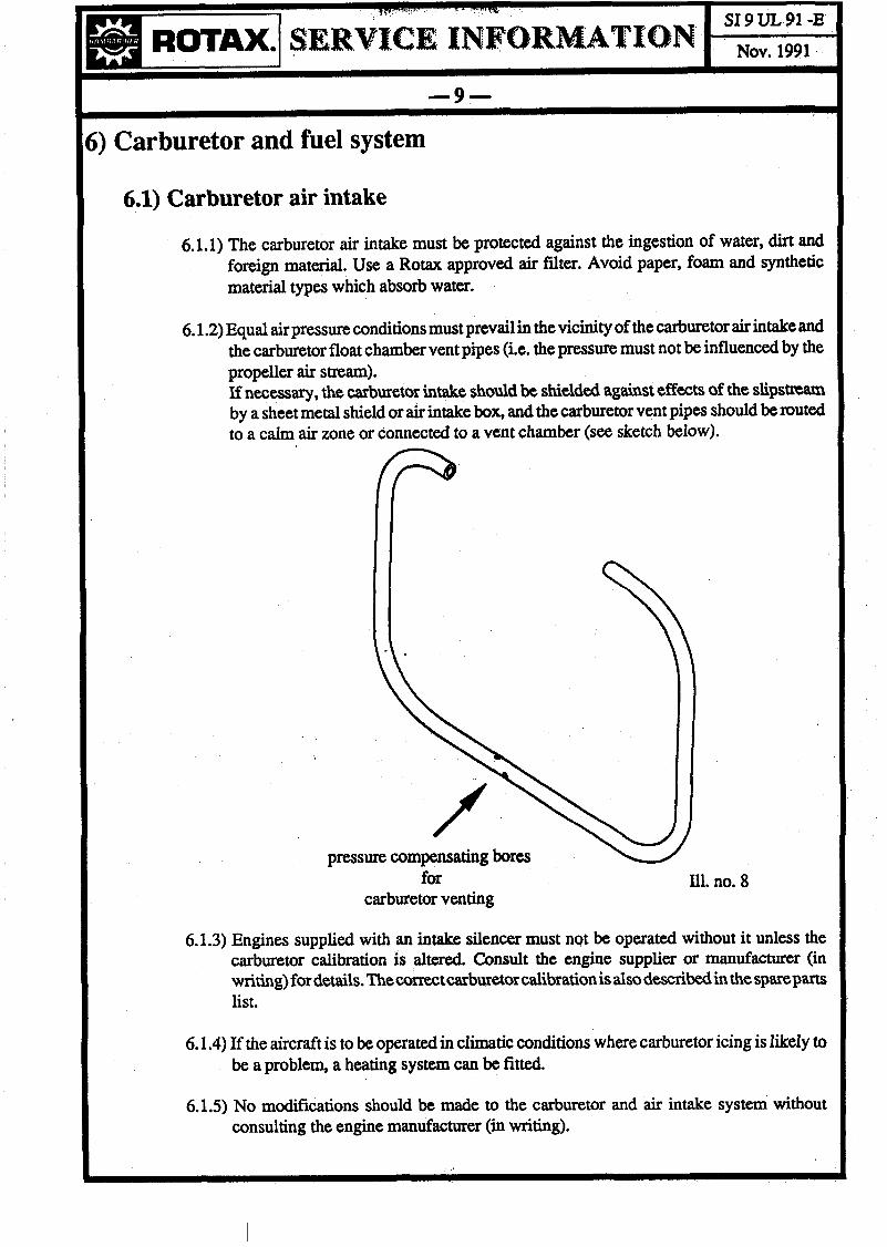
6.1.2) Equal air pressure conditions must prevail in the vicinity of the carburetor air intake and the carburetor float chamber vent pipes (i.e. the pressure must not be influenced by the propeller air stream). If necessary, the carburetor ink&e should be shielded against effects of the slipstream by a sheet metal shield or air intake box, and the carburetor vent pipes should be routed to a calm air zone or connected to a vent chamber (see sketch below).
pressure compensating bores - for Ill. no. 8
carburetor venting
6.1.3) Engines supplied with an intake silencer must not be operated without it unless the carburetor calibration is altered. Consult the engine supplier or manufacturer (in writing)fordetails.Thecorrectcarburetorcalibrationis alsodescribedinthe spareparts list.
6.1.4) If the aircraft is to be operated in climatic conditions where carburetor icing is likely to be a problem, a heating system can be fitted.
6.1.5) No modifications should be made to the carburetor and air intake system without consulting the engine manufacturer (in writing).

6.2) Fuel system
6.2.1) The carburetor(s) is (are) supplied with fuel by the fuel pump provided with the engine.
6.2.2) The pump is actuated pneumatically via an ,,impuIse line“ leading from the nipple on the crankcase to the fuel pump. This line should not be longer than 500 mm (20 in.) and must be of stiff and fuel-resistant material.
6.2.3) The fuel pump should be installed in a cool place (not on the engine itself), with the small drain hole near the impulse connection towards the bottom. This hole drains oil condensate from the pump diaphragm chamber.
If possible, the pump should be located below the fuel tank level.
If the fuel tank is considerably lower than the engine, an electric pump (e.g. Facet Solid StateElectricPumptype 480615orPierburgtype7.21440.01 =Rotaxpartno. 996730) should be used. This pump is to be connected in parallel as in case of series-connection the fuel pressure would be excessive.
The electric pump must produce a pressure of minimum 0,2 bar (3 lb.squ.in.), and together with the pneumatic pump max. 0,5 bar (7 lb.squ.in.) resp. max. 0,4 bar (6 lb.squ.in.) in case of a diaphragm carburetor, and must allow free flow-through even when switched off.
6.2.4) A suitable fuel filter of 0,15 mm mesh size must be fitted between pump and carburetor. Don’t use paper filters. The fuel tank should have a drain cock for condensed water. A screen of 0,3 mm mesh size should be fitted to the fuel line in the tank. By no means the normal fuel flow should be restricted.
6.2.5) The fuel lines and impulse line must be of a type to comply with national regulations. The minimum passage diameter is 5 mm (0,2 in.).
6.2.6) If the fuel tank is placed higher than the carburetor, the tank connection must have a fuel cock (with filter) to shut off the fuel supply when the engine is not running.
Reason: The carburetor needle valve is not sufficiently tight to seal for a prolonged period of time and during transport.
National regulations may require a fuel cock to be fitted even if the tank is below the carburetor.

6.2.7) To check the fuel system for free flow, fit a piece of transparent tube in the fuel system and make a check run. At full load operation and high ambient temperature, only a few gas bubbles should be seen. Avoid by all means restriction of fuel flow by the fuel cock.
’ The pressure in the fuel line between pump and carburetter must be minimum 0,2 bar (3 lb.squ.in.) andmaximum 0,5 bar= 7 lb.squ.in. (resp. 0,4 bar = 6 lb.squ.in. in case of a diaphragm carb - see paragr. 6.2.3) to ensure sufficient fuel supply.
6.2.8) If you have problems with the fuel supply, modify one test float chamber by inserting 2plexiglass windows into the side walls and observe fuel level, if possible while flying:
- if fuel level is lowering continuously, check needle valve and fuel pump,
- if fuel is foaming, checkresp. modify motormounts to reduce vibrations on carburetor.
6.3) Oil pump - separate oil lubrication
6.3.1) Function .
In this case the engine is equipped with a gear-driven oil pump to supply an adequate quantity of Zstroke oil to each cylinder. The oil pump is a plunger type with metering system. The amount of oil is detwmintd by engine r.p.m. and lever position. This lever is actuated by a Bowden cable connected with the throttle cable. The oil pump is gravity-fed from an oil tank. In case of oil pump lubrication the carburetters are supplied with pure fuel (no mixture).
6.3.2) Oil quality
Use high performance 2- stroke oil as per specifications TSC- 3 or ISO- LETC or API TC. The pour point should be 10 ‘C (=18 ‘F) below the lowest ambient temperature to be expected.

6.3.3) Installation
1) Oil tank capacity: The oil tank should be of more than 5 % of the fuel tank capacity.
2) The oil tank bottom outlet must not be below the oil pump inlet nipple, even with the greatest possible inclination of the aircraft (i.e. dimension HS must be greater than zero, see ill. no. 10).
3) Use a stiff, oil-resistant suction pipe which cannot be squeezed. Secum it with clamps at the connections.
4) Install an adequate oil filter (e.g. Rotax part no. 956 330) between oil tank and oil
pump.
5) Install a Bowden cable to actuate the pump lever simultaneously with the carburetors.
Attention: If the pump cable breaks or unhooks, the oil pump is set to minimum discharge.
6) Adjustment of oil injection pump alignment marks: At throttle lever idle position the 2 marks must align (see ill. no. 9).
7) Vent the suction pipe before engine start by opening the vent plug (see ill. no. 9, pos. 9) until all air is vented from that line. Close vent plug carefully.
8) It is recommended to fill the first tank of fuel with a fuel/oil mixmre at a mixing ratio of 100 : 1. This is for safety until the whole system is properly filled with oil.
6.3.4) Service
1) Check oil tank content before every flight and refR if necessary.
2) Check oil lines, nipples, connections, oil pump lever adjustment at every preflight check.
3) Verify that the oil consumption is approximately of a ratio of 1 : 50 up to 1 : 70 of the fuel consumption.
Note: This oil injection will not affect or replace the rotary valve gear lubrication nor the reduction gearbox lubrication.

-13-
6.3.5) Examples of installation
0 Engine 0 oiltank (D Suction line
.Q Oil pump 8 Discharge line @ Check valve 0 Oil intake port 0 Adjuster nuts 8) Vent plug (ID Oil filter
Ill. no. 9
Ill. no. 10

SERjf1f-E XN~fJ~&JA,TH(‘JN
-14-
‘) Ignition system and electrical equipment
7.1) Connect the wires as per wiring diagram in the manual. Before operating the engine make sure the ignition shorting wire is connected to the switch and is working. A 2-pole switch connected to mass is recommended.
7.2) The ignition and lighting cables must not touch the cylinder or cylinder head in order to avoid chafing or burning of the wires.
7.3) R.F.I. (Radio Frequency Interference) suppression
If for certain applications the grade of radio interference has to be reduced, or a completely interference free ignition unit is required, the following changes and/or modifications are possible:
7.3.1) Use of shielded sparkplug connectors (ROTAX part no. 983 409) and shielded high tension leads.
7.3.2) Exchange of the stand.ard spark plugs to resistor plugs (e.g. NGK BR 8 ES).
7.3.3) For engines with contact breaker ignition a kit for total R.F.I. suppression is available as optional equipment.
3) Exhaust system
8.1) Fundamental: The exhaust system is tuned to the engine to give the correct performance and must not be modified. If however changes are necessary for installation purposes, then the original medium length of the pipe between the exhaust manifold and the muffler must be respected and maintained (ill. no. 11). If modifications are necessary, consult the engine manufacturer (in writing). Check operation with standard exhaust system first, before modifying the system.
Ill. no. 11 medium pipe length

8.2) Mounting of exhaust system
The exhaust system is to be mounted on vibration-damping elements and secured against loss. Take care that the ball joints are not under tension.
- All ball joints should be lubricatedregularly with heat-resisting grease (e.g. LOCI’ITE Anti- Seize, Rotax part no. 297 431) to aIlow them to move freely and thus avoid breakage of the muffler system.
- Secure the exhaust springs with wire-lock to prevent them from loss and vibration. See Service Information 11 UL-87-E, page 5.
9) Vibration and noise damping
Both engine and propeller are considered as ,,noise sources“.
9.1) The propeller often is the louder source of noise. Besides the propeller shape, the tip speed and the radial and axial distance of the propeller blades from the engine, the engine mounts and the fuselage have an important influence on the noise level. Pusher propellers operate in a turbulent airstream and consequently are louder.
9.2) The engine noise can be subdivided into engine-, air intake-, exhaust noise and mechanical noise which gefs transmitted via the engine suspension into the fuselage.
On the intake and exhaust system, modifications are not allowed without contacting the engine manufacturer (in writing).
The uncomfortable noise in the aircraft can be improved by elastic mounting of the engine (on anti-vibration blocks).
10) Rotary valve drive
The water-cooled rotary valve engines have a 90’ helical gear drive in the crankcase between the 2 cylinders.
10.1) Lubrication of rotary valve drive
There are 2 tubes on the crankcase where oil lines have to be connected to an oil tank.
The oil line 0 coming from the oil tank must be connected to the tube on crankcase below the rotary valve. The vent line 8 between the cylinders must be connected to the higher placed oil tank (see illustration).
Fill the oil circuit with high-performance a-stroke oil (the same as used for the fuel/oil mixture). The oil level should be between minimum and maximum mark of the oil tank (see illustration).

-16-
10.2) Oil circuit for engine installation with spark plugs ,,up“
0 crankcase
Q cylinder
(D cylinder head
0 oil feed line
Ca vent line
0 oil tank
0 spark plug
0 vent screw
ill. no. 12
10.3) Oil circuit for engine installation with spark plugs ,,down“
In this case the oil system for ro& valve drive and water-pump drive has to be modified by the craft manufacturer as per the following illustration. During oil refilling remove vent screw 0.
0 crankcase
8 cylinder
6) cylinder head
0 oil feed line
8 vent line
0 oil tank
0 spark plug
0 vent screw
IMPORTANT - ATTENTION: For inverted installation (spark plugs down), the oil tank must be removed from the support plate and installed in a suitable location

sER,vIcE, I~~f-JR&&$T~o@
-17-
11) Operational limit values :
with air cooling with liquid cooling
engine speed see engine data sheet see engine data sheet
temperature at spark plug seat 250’ C (480°F) 180’ C (355’ F)
- difference between 2 cylinders: 2o’C (36’F) 10’ C (18.F)
exhaust gas temperature (EGT): 65o’C (12OOF) 650’ C (12OO.F)
- difference between 2 cylinders: 25’ C (45’ F) 25’ C (45’ F)
- crankcase temperature 80’ C (175’ F) 80’ C (175’ F)
- cooling liquid temperature 80’ C (175’ F)
12) Instruments
Also engines for ultralight and experimental aircraft need a ,,certain“ instrumentation. Listed as per priority of importance, we suggest to measure the following:
- Engine speed - Cooling liquid temperature on liquid-cooled engines - Spark plug seat temperature - Exhaust gas temperature.
For detailed information, see Service Information 6 UL 87-E on instruments.

-18-
13.)Installation instructions for gearboxes
13.1) For ROTAX engine type 277:
1) Engine PTO crankcase must have machined centering and 4 threads M8.
2) This paragraph is only applicable for execution ,,propeller shaft offset towards cylinder“:
Fit adapter plate and gasket with Allen screws M8 x 25 to crankcase, PTO side. Secure the screws with LOCTITE 221 on the threads, and with LOCI’ITE 648 below the screw heads.
ATTENTION: No lock-washers arc used with these screws!
All further paragraphs apply to both executions, i.e. propeller shaft offset towards cylinder (,,Z“) and propeller shaft offset towards engine base (,,S“):
NOTE: The drive gears for these 2 versions are different!
3) Clean and degrease taper of engine PTO shaft carefully with suitable degreasing agent. Also degrease the l/2” bolt and PTO shaft internal threads. 4) Fix drive gear with l/2” bolt, washer and lock washer, use LOCTITE 221 only on threads, not on taper! Torque for l/2” bolt: 60 Nm (530 in.lb.).
5) Screw the 4 studs into the engine crankcase or into the adapter plate (depending on configuration). Use LOCTITE 221 on the threads. Torque for studs M8: 8 Nm (70 in.lb.). Fit the gasket. Bolt the gearbox ass’y onto the engine using 4 nuts M8 and lock washers. Torque for nuts M8: 24 Nm (210 inlb.).
6) Make sure that the magnetic oil drain plug is at the bottom and the vent plug is at top. Secure the magnetic drain plug with wire-lock.
7) Only applicable for execution with separate aluminium propeller flange (propeller shaft in 2 parts):
Degrease gearbox PTO shaft, threads and bolt Ml2 x 1.5 LH (left hand). Mount propeller hub with LOCTITE 221 on taper and threads. Torque: 60 Nm (530 in.lb.). IMPORTANT: Left hand threads!
8) Prop hub is drilled for 6 x l/4” (or 6 x M8) bolts. These bolts are not supplied by ROTAX.
9) Fill the gearbox up to the lower oil level screw with an SAE grade 90 gear oil (of specification API-GL5 or higher). Secure level screw and vent plug with wire-lock.

-19-
10) Safety is everyone’s business. Help assure secure and troublefree operation by observing above instructions. In case of doubt contact your authorized workshop.
11) Mounting and maintenance operations must be done only by skilled personnel.
13.2) For ROTAX engines type 377,447,462,502,508,532 and 582:
13.2.1) Gearbox version “A” = with adapter plate
1) Clean contact surfaces of adapter plate and crankcase. Apply LOCTITE 221 to the sealing surfaces of gearbox housing and adapter plate. Fit the O-ring in the groove of the adapter plate and fix the plate in position with the 4 Ml0 Allen screws. Before tightening the screws, apply LOCTITE 648 to the underneath of the screw heads. Torque for Ml0 bolts: 55 Nm (490 in.lb.). No lock-washers are used with these Allen screws.
Note: The gearbox can be fitted with the propeller shaft either above or below the crankshaft axis. Ensure that the adapter plate is fitted the correct way up for the required gearbox position.
2) Clean and degrease taper of engine PTO shaft carefully with suitable degreasing agent. Degrease also l/2” bolt and PTO shaft threads.
3) Fix drive gear with l/2” bolt, washer and lock washer, use LOCTII’E 221 only on threads, not on taper. Torque for l/2” bolt: 60 Nm (530 inlb.).
4) Screw the 4 studs into the adapter plate. Use LOCI’ITE 221 on the threads. Torque for studs M8: 8 Nm (70 inlb.). Fit the O-ring in the groove of the adapter plate. Bolt the gearbox ass’y onto the engine using 4 x M8 nuts and lock washers. Torque for nuts M8: 24 Nm (210 inlb.).
5) Make sure that the oil drain plug is at the bottom, and the vent plug is at top of the gearbox. Secure the drain plug with wire-lock.
6) Only applicable for execution with separate aluminium propeller flange (propeller shaft in 2 parts):
Degrease gearbox PT.0 shaft, threads and bolt Ml2 x 1.5 LH (left hand). Mount propeller hub with LOCTITE 221 on taper and threads. Torque: 60 Nm (530 in.lb.). IMPORTANT: Left hand threads!
7) Propeller hub is drilled for 6 x l/4” (or 6 x M8) bolts. These bolts are not supplied by ROTAX. *

8) Fill the gearbox up to the lower oil level screw with an SAE grade 140 EP or SAE 85 W - 140 EP gear oil (of specification API-GL5 or higher). Secure oil level screw and vent plug with wire-lock.
Oil quantity: with propeller shaft downward: approx. 300 cm3 / 18,5 inch3 with propeller shaft upward: approx. 330 cm3 / 20 inch3
9) Safety is everyone’s business. Help assure secure and troublefree operation by observing above instructions. In case of doubt contact your authorized workshop.
10) Mounting and maintenance operations must be done only by skilled personnel.
13.2.2) Gearbox version “B” = without adapter plate
1) Clean and degrease taper of engine PTO shaft carefully with suitable degreasing agent. Degrease also l/2” bolt and PTO shaft threads.
2) Fix drive gear with l/2” bolt, washer and lock-washer, use LOCTITE 221 only on threads, not on taper. Torque for l/2” bolt: 60 Nm (530 in.lb.).
3) Clean contact surfaces of gearbox housing and crankcase. Depending on configuration screw 2 or -4 studs secured with LOCTITE 221 into the crankcase (torque 8 Nm/ 70 in.lb.). Apply LOCTITE 648 to the gearbox housing, place O-ring into the groove and fit complete gearbox on the crankcase centering flange. Depending on configuration, fix the gearbox with 4 lock-washers and 4 hex. nuts M8 (respectively with 4 lock washers, 2 hex. nuts M8 and 2 hex. screws) on engine. Torque 24 Nm / 210 in.lb.
4) This paragraph refers only to gearbox ,,B“ fitted to engines 532 and 582:
For these engine types a gearbox housing with 6 fixation points is used. Remove gearbox cover from gearbox housing. Clean contact surfaces on gearbox housing and crankcase. Screw 2 studs, secured with LOCTITE 221, into the crankcase (torque 8 Nm / 70 in.lb).
Apply LOCTITE 648 to the gearbox housing, place O-ring into the groove and fit gearbox housing on the crankcase centering flange. Fix gearbox housing with 2 hex. collar screws (torque 24 Nm / 210 in.lb.). ATTENTION: Lubricate the cutting edge of the screw collar. Place gearbox cover on gearbox housing and fix it with 4 lock-washers, 2 hex. nuts M8 and 2 hex. screws M8 (torque 22 Nm/ 195 inlb.).

5) The gearbox can be-fitted with propeller shaft either above or below the crankshaft axis. Make sure that the oil drain plug is at bottom and the vent plug is at top of the gearbox. Secure the drain plug with wire-lock.
6) The propeller hub is drilled for 6 x l/4” (or 6 x M8) bolts. These bolts are not supplied by ROTAX.
7) Fill the gearbox up to the lower oil level screw with SAE grade 140 EP or SAE 85 W - 140 EP gear oil (of specification API-GL5 or higher). Secure oil level screw and vent plug with wire-lock.
Oil quantity: with propeller shaft downward approx. 300 cm3 / 18,5 inch3 with propeller shaft upward: approx. 330 cm3 / 20 inch3
8) Safety is everyone’s business. Help assure secure and troublefree operation by observing above instructions. In case of doubt contact your authorized workshop.
9) Mounting and maintenance operations must be done only by skilled personnel.
13.2.3) Gearbox version “C“
1) Clean contact surfaces of gearbox and crankcase. Clean flywheel taper, crankshaft taper, l/2” threads in crankshaft taper and threads of l/2” screw with suitable degreasing agent. Fit the flywheel with l/2” hex. screw and washer to the PTO side crankshaft taper. Secure the screw with LOCIITE 221 (torque 60 Nm / 530 in.lb.).
Fix the preassembled unit ofHardy disk/coupling flange to the flywheel with 3 Allen screws (secured with LOCTITE 221) and parallel flats washers (kept with fork wrench 17 mm a/f in position, in order not to distort the Hardy disk). Torque 40 Nm / 350 in.lb.).
Attention: Now the steel clamping strap around the Hardy disk must be removed.
2) Remove the gearbox cover from gearbox housing, the pinion shaft and the shims.
Attention: These shims may adhere or fall down.
The end play of the shaft has been detemrincd at the factory and compensated to zero by these shims. The necessary end play is obtained by the gasket between gearbox cover and gearbox housing.

3) Fit the gearbox housing to the crankcase. Insert the pinion shaft through the bearing into the coupling flange. Take care that all shims for end play compensation be fitted in the same quantity and position as fitted before, and that the splines of the pinion shaft be coated with LOCTITE Anti-Seize. Turn the Allen screw with lock- washer for fixation of the pinion shaft by some turns of thread into the collar nut. Fix the gearbox housing with 8 hex. collar screws M8 (torque24 Nm/210 in.lb.). Apply ball bearing grease to the screw head contact surfaces. Then tighten Allen screw M8 x 35 at 24 Nm / 210 in.lb.
Fit the gearbox cover to the gear housing. Fit the gasket only dry! Tigtening torque for 11 Allen screws M6 x 30: 10 Nm / 90 in.lb.
4) Then fit the fill-, drain- and check screws and fill gearbox with oil. Oil quantity: with propeller shaft downward: approx. 120 cm3 / 7,5 inch3
with propeller shaft upward: approx. 200 cm3 / 12 inch3
Oil quality: SAE 140 EP or SAE 85 W - 140 EP gear oil (of specification API-GL5 or GL6).
5) Secure the magnetic screw and capstan screws with wire-lock.
6) Please, observe all tightening torques and indications of Loctite and grease applications.
7) The propeller hub is drilled for 6 x l/4” (or 6 x M8) bolts. These bolts are not supplied by ROTAX.
8) Safety is everyone’s business. Help assure secure and troublefree operation by observing above instructions. In case of doubt contact your authorized workshop.
9) Mounting and maintenance operations must be done only by skilled personnel.