service guide for warn pullzall 120vac - … · service guide for warn pullzall 120vac ......
TRANSCRIPT
987604A2.doc Page 1 of 48
SERVICE GUIDE
For
WARN PULLZALL 120Vac
P/N 885000 & 885001
� REPAIR / REPLACEMENT INSTRUCTIONS
� TROUBLE SHOOTING GUIDE

987604A2.doc Page 2 of 48
WARNING
This guide identifies potential hazards and has important safety messages that help you and
others avoid personal injury or death. WARNING and CAUTION are signal words that
identify the level of hazard. These signal words mean:
WARNING signals a hazard that may cause serious injury or death, if you do not follow
recommendations. CAUTION signals a hazard that may cause minor to moderate injury,
if you do not follow recommendations.
This guide uses NOTICE to call attention to important mechanical information, and
Note: to emphasize general information worthy of special attention.
Notice
� This guide has been provided for use by WARN Authorized Service Centers. Any
other use is prohibited.
Caution
Moving parts entanglement hazard
Failure to observe these instructions could lead to minor or moderate injury
� Always take time to fully read and understand the Instructions.
� Never operate this product if you are under 16 years of age.
� Never operate this product when under the influence of drugs, alcohol or medications.
Read instructions thoroughly
Notice
Equipment damage
� Always refer to the Wiring Diagram for all wiring schematics and specific details on how
to wire this WARN product.
Read instructions thoroughly.

987604A2.doc Page 3 of 48
CONTENTS
1. GENERAL DESCRIPTION 04
2. DISASSEMBLY AND ASSEMBLY
2.1. Suggested Tools 06
2.2. Housing 07
2.3. Gear Train Assembly 11
2.4. Motor 18
2.5. Wire Rope Assembly 24
2.6. Safety Hook 29
2.7. Tail Hook 33
2.8. Drum Assembly 38
2.9. Wiring Diagrams 39
2.10. Torque Specifications 47
3. PULLZALL TROUBLE SHOOTING 48
4. SERVICE PART LIST 50

987604A2.doc Page 4 of 48
1. GENERAL DESCRIPTION
The PullzAll is a powerful, lightweight, easy-to-use handheld electric tool with the ability to lift or
pull up to 1,000 lbs / 454 kg. A strong Motor and Variable Speed Trigger Switch for power in and
power out operation, Wire Rope and Clasp Hook will allow you to move heavy items into place
smoothly and precisely. These features equate to saving both time and money.
The PullzAll will help get the job done easier, faster, and with less manual labor than a come-a-
long or chain fall, making you more productive. The PullzAll is for the tradesperson, farmer /
rancher, or anyone that needs to lift or pull up to 1,000 lbs / 454 kg. This makes PullzAll ideal for
construction, pipe fitting, iron work, equipment and plant maintenance, farm and ranch use, auto
shops, garages, machine shops, home improvement, hunting, camping, and more.
PullzAll 120v AC Specifications:
1. Part number 885000.
2. Light weight and portable.
3. Powerful 120 Volt AC Motor.
4. 1,000 lbs (454 kg) lifting / pulling capacity.
5. 15'(4.6m) of 7/32"(0.56cm) diameter Wire Rope.
6. Variable Speed Control for precision load placement.
7. Convenient forward/reverse Switch.
8. Electronic Load Limiter with LED indicator for operator feedback.

987604A2.doc Page 5 of 48
Runs on 120v
AC Power
15’ of 7/32” Wire
Rope with Industrial Grade Hook
Versatile Swivel
Anchor Hook
Electronic Load
Limiter with LED
Indicator for Operator
Feedback
Handle with Trigger
for Variable Speed
Control
Convenient
Forward/Reverse
Switch
1000 lbs/454 Kg
Lifting/Pulling
Capacity
987604A2.doc Page 6 of 48
2 DISASSEMBLY AND ASSEMBLY
2.1 SUGGESTED TOOLS
1. Hammer
2. Snap ring plier
3. Allen key set
4. Screw driver
5. Cutting plier
6. Pin remover (Punch)
7. Insulation tape
8. Gloves

987604A1.doc Page 7 of 48
2.2 HOUSING
Before opening the Housing follow the below instructions:
Power Cord Always unplug the product while rigging, when not in use or during maintenance and cleaning.
2.2.1 REMOVAL OF HOUSING
1. Remove the screws (#6 x .75), Qty 7
from Handle.
2. Remove the screws (#8 X 1.25), Qty
6 from the main body of the Housing.

987604A1.doc Page 8 of 48
3. Keep the assembly on the work bench
facing the Cover in the direction as
shown in the figure.
4. Remove the Plastic Housing -left
hand from the assembly as shown in
the figure.
5. Remove the Main Chassis from the
Plastic Housing - right hand and place
it on the work bench.

987604A1.doc Page 9 of 48
2.2.2 ASSEMBLY OF HOUSING
1. Install the Main Chassis in the Plastic
Housing - right hand as shown in the
figure.
2. Install the Plastic Housing -left hand
on the assembly as shown in the
figure.
3. Flip the assembly as show in the
figure.

987604A1.doc Page 10 of 48
4. Install the screws (#8 X 1.25), Qty 6
from the main body of the Housing.
5. Install the screws (#6 x .75), Qty 7
near Handle.
Note: When replacing the Housings with a Housing Service kit, be sure to affix ALL appropriate
labels from the service kit onto the new housings, using the housings being replaced as a guide for
placement of your new labels. Your service kit will include extra labels for other languages and
markets that can be discarded after you select the ones needed for your product.

987604A1.doc Page 11 of 48
2.3 GEAR TRAIN ASSEMBLY
• If the gearsets are worn or damaged, the entire PullzAll must be replaced, no replacement
parts are available.
2.3.1 GEAR TRAIN ASSEMBLY REMOVAL
1. Remove Retaining Ring from Idler
Gear.
2. Remove Wear Washer from Idler
Gear.
3. Remove Retaining Ring from Helical
Gear Press. Remove Wear Washer
from Helical Gear.

987604A1.doc Page 12 of 48
4. Remove Helical Gear from Gear
Housing.
5. Remove 3 Cap Screws(#3 x .75) from
Gear Housing through Left side
Bracket of Chassis assembly.
6. Remove Gear Housing from left side
Bracket of Chassis assembly.
7. Remove Carrier Assembly from
Ring.
987604A1.doc Page 13 of 48
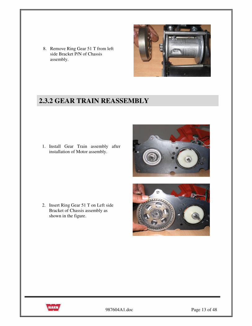
8. Remove Ring Gear 51 T from left
side Bracket P/N of Chassis
assembly.
2.3.2 GEAR TRAIN REASSEMBLY
1. Install Gear Train assembly after
installation of Motor assembly.
2. Insert Ring Gear 51 T on Left side
Bracket of Chassis assembly as
shown in the figure.

987604A1.doc Page 14 of 48
3. Install Ring Gear 48T P/N 73225 and
Carrier Assembly P/N 73227 in Gear
Housing P/N 75077.
4. Install Gear Housing on Left side
Bracket of Chassis assembly aligning
dowel pins.
5. Install 3 Cap Screws (#3 x .75) in
Gear Housing through Left side
Bracket of Chassis assembly.
6. Install Helical Gear on Gear Housing
as shown in the figure.

987604A1.doc Page 15 of 48
7. Install Wear Washer on Helical Gear
Press.
8. Install Retaining on Helical Gear.
9. Install Idler Gear on Gear Housing.
10. Install Wear Washer and Retaining
Ring on Idler Gear.

987604A1.doc Page 16 of 48
2.3.3 INSPECTION OF GEAR TRAIN
1. Check each Idler Gear to make sure that all teeth are present in good condition.
2. Check each Sun Gear to make sure all teeth are present and in good condition.
3. Check each side of each Sun Gear to make sure there are no grooves from wear. Replace
the Gear Set if worn.
4. Check Carrier Assembly to make sure that Planet Gears are tight. Each Gear should be able
to move a small distance when pulled from and pushed toward center of Gear Set. All
Planet Gears should have about the same amount of movement. Replace Carrier Assembly
if Planet Gears are loose.
5. Push each Planet Gear against its axle pin and rotate the Gear completely. The Gear must
turn smoothly on Pin. Replace Gear Set if Planet Gears do not turn smoothly.
6. Check the Ring Gear 48T inside the Gear Housing. All the Gear teeth must be in good
condition and they must be free of debris. The Gear Housing must be replaced if teeth have
a wear groove.
7. If the Gear sets are worn or damaged, the entire PullzAll must be replaced, no replacement
Parts are available.
987604A1.doc Page 17 of 48
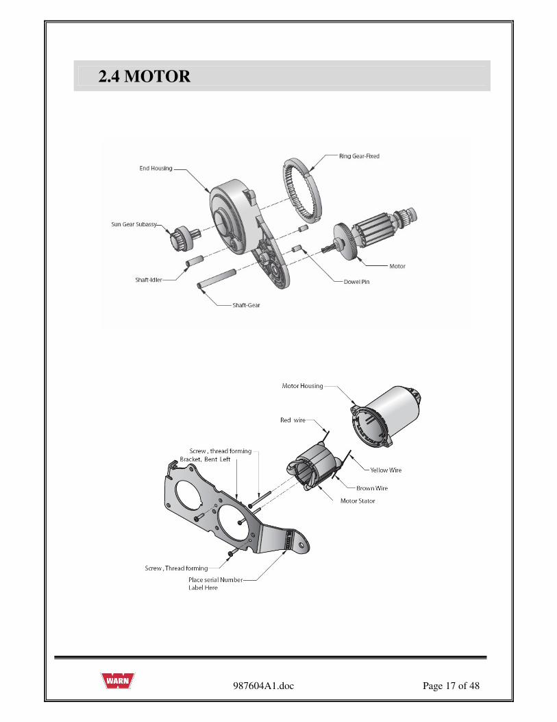
2.4 MOTOR

987604A1.doc Page 18 of 48
2.4.1 REMOVAL OF MOTOR
Before removing the Motor follow the instructions given below:
1. Remove the Gear Train assembly.
2. Remove the 2 screws (#8 x 0.75) from
Chassis assembly.
3. Remove the left side cap screw and nut
from Hawse Fairlead assembly.

987604A1.doc Page 19 of 48
4. Remove cap screw from Chassis
assembly as shown in the figure.
5. Remove Left side Bracket from Chassis
assembly.
6. Remove Motor assembly from Chassis
assembly after removal of Wiring leads

987604A1.doc Page 20 of 48
2.4.2 ASSEMBLY OF MOTOR
1. Connect all Wire leads from Motor
assembly and install in to Chassis
assembly as shown in the figure.
2. Install Left side Bracket on Chassis
assembly as shown in the figure.
3. Install cap screw in Chassis assembly as
shown in the figure.

987604A1.doc Page 21 of 48
4. Install the left side cap screw and nut
from Hawse Fairlead assembly.
Install 2 screws (#8 x 0.75) in Chassis
assembly.
2.4.3 MOTOR INSPECTION
• Visual inspection.
• While assembling the Motor ensure that, Motor has been properly placed inside the End
Housing and the screw had been properly tightened.

987604A1.doc Page 22 of 48
2.5 WIRE ROPE ASSEMBLY
2.5.1 REMOVAL OF WIRE ROPE
Note:
Prior to disassembly:
1. Spool out all Wire Rope.
2. Use of gloves is recommended while handling frayed or damaged Wire Rope.
3. Unplug unit before disassembly.
Tasks:
Disassemble the Drum and Wire Rope.
1. Push the Wire in the direction of the
arrow mark as shown in the figure.
2. Using a punch or drift and hammer, hit
the end of the Wire Rope to push the
loop back through the Drum.

987604A1.doc Page 23 of 48
3.Use the Pin remover (punch) to remove
the Wire Rope and Stop Button from the
Drum.
4. Straighten the bent Rope and pull the
Rope out of Drum hole in the arrow
direction as shown.
5. Remove the Hawse Fairlead from the
Bracket of the Chassis.
6. Remove and discard Tension Plate (if
equipped).

987604A1.doc Page 24 of 48
2.5.2 ASSEMBLY OF WIRE ROPE
1. Assemble the Hawse Fairlead to the
Bracket of the Chassis.
2. Tighten the CapScrews with Allen key and
opened end wrench.
3. Keep the insulation tape to the edge of the
Wire Rope.

987604A1.doc Page 25 of 48
4. Insert the Wire Rope into the Drum through
the Hawse Fairlead.
5. Pull the wire from the other end of the
Drum hole.
6. Bend the Wire Rope and insert in to the
same hole in the direction shown in the
figure.
7. Pull the Wire Rope from the hole as shown
in the figure.

987604A1.doc Page 26 of 48
8. Support one edge of the Wire and pull the
other Wire as shown in the figure.
9. Verify Wire Rope stop button is inserted
into the loop as shown before pulling the
Wire Rope tight.
10. Hit wire rope loop with a hammer, so that
the Wire Rope will be pushed in to the rope
retention hole.
11. Check the Wire Rope so that it enters
completely into the Drum hole.

987604A1.doc Page 27 of 48
12. Check from the other side of the Drum
whether the Wire Rope is perfectly
assembled to the Drum.
2.5.3 INSPECTION OF WIRE ROPE
• Inspect the Wire Rope for signs of wear or damage. Worn and damaged parts must be
replaced.
• See the Rope for damage for kinks, cuts, knots, mashed or frayed portions and broken
strands.
• Keep the Rope free from contaminants. Use a clean towel to remove the dirt and debris.
• Use of light oil on the Wire Rope can prevent corrosion.

987604A1.doc Page 28 of 48
2.6 SAFETY HOOK
2.6.1 REMOVAL OF SAFETY HOOK
To remove Safety Hook follow the below instructions:
1. First straighten the bent end of the Cotter
Pin by using Cutting plier and then pull out
the Cotter Pin by holding head of the Cotter
Pin with the help of cutting plier from the
Pin.

987604A1.doc Page 29 of 48
2. Remove the Pin from the Hook and Rope.
3. Remove the Safety Hook from Wire Rope

987604A1.doc Page 30 of 48
2.6.2 ASSEMBLY OF SAFETY HOOK
To Reassemble Safety Hook follow the below instructions:
1. Place the
Safety Hook and align the mounting holes
with the loop of the Wire Rope
2. Insert the Pin through Safety Hook and
Wire Rope loop.
3. Insert the Cotter Pin inside the hole of the
Pin and bend the ends of the Cotter Pin with
the help of Cutting pliers.

987604A1.doc Page 31 of 48
2.6.3 INSPECTION OF SAFETY HOOK
• Inspect the Hook for signs of wear and damage.
• Hook damage examples: cracks, twisted components, excessive opening, seat wear, loose
or damaged safety latch or corrosion.

987604A1.doc Page 32 of 48
2.7 TAIL HOOK
Original Tailhook Assy
2nd Generation Tailhook Assy Service Part Tailhook Assy

987604A1.doc Page 33 of 48
2.7.1 REMOVAL OF TAIL HOOK
To remove Tail hook follow the below instructions:
1.Remove bolt and nut from the Chassis assembly
through Tail Hook.
2.Loose the cap screw with Allen key before
removing the Tail Hook and Spacer Pin from
Chassis assembly.

987604A1.doc Page 34 of 48
2.7.2 ASSEMBLY OF TAIL HOOK
To reassemble the Original Tailhook follow the below instructions:
1.Tighten the cap screw after place Tail
Hook and Spacer Pin between the Bracket
holes.
2.Assemble the bolt and nut.

987604A1.doc Page 35 of 48
To reassemble the Second Generation Tail Hook follow the instructions:
1. Place Spacer Bracket in Chassis
assembly with capscrew and then apply
the torque.
2. Take the Tail Hook and align the
mounting holes with the Spacer Bracket
holes and Chassis assembly.

987604A1.doc Page 36 of 48
3. Insert the Pin through the Hook
assembly.
4. Insert the Cotter Pin inside the hole of the
Pin and bend the ends of the Cotter Pin
with the help of pliers.
2.7.3 TAIL HOOK INSPECTION
• Inspect the Hook for signs of wear and damage
• Hook damage examples: cracks, twisted components, excessive opening, seat wear, loose
or damaged safety latch or corrosion.

987604A1.doc Page 37 of 48
2.8 DRUM ASSEMBLY
• If the drum is worn or damaged, the entire PullzAll must be replaced, no replacement parts
are available.
987604A1.doc Page 38 of 48
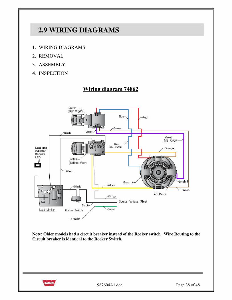
2.9 WIRING DIAGRAMS
1. WIRING DIAGRAMS
2. REMOVAL
3. ASSEMBLY
4. INSPECTION
Wiring diagram 74862
Note: Older models had a circuit breaker instead of the Rocker switch. Wire Routing to the
Circuit breaker is identical to the Rocker Switch.

987604A1.doc Page 39 of 48
WIRING DETAILS
• Route black lead Wire from J3 terminal on Circuit Board through Wire guides up into handle
to Trigger Switch.
• Route black lead Wire from J2 terminal on circuit board through Wire guides up to Rocker
Switch.
• Route white lead Wire from J4 terminal on circuit board through Wire guides up to Trigger
Switch.
• Route the Motor wires as shown.
• Route Brush leads from Brushes up to Trigger Switch.
• Use tie strap to secure Motor Wires and Brush Wires to the right hand frame.
• Attach green Wire from Power Cord assy. to frame as shown.
• Refer Wiring diagram 74862 for installation Wiring schematic.
Switch Pin-out Table
Manufacturer name is embossed on switch.
987604A1.doc Page 40 of 48
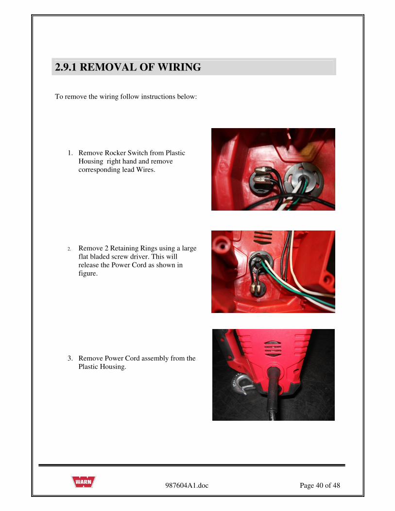
2.9.1 REMOVAL OF WIRING
To remove the wiring follow instructions below:
1. Remove Rocker Switch from Plastic
Housing right hand and remove
corresponding lead Wires.
2. Remove 2 Retaining Rings using a large
flat bladed screw driver. This will
release the Power Cord as shown in
figure.
3. Remove Power Cord assembly from the
Plastic Housing.

987604A1.doc Page 41 of 48
4. Remove the Wire leads from Trigger
Switch.
5. ONLY Remove green Ground Lead
Wire from Chassis when replacing
power cord.
6. Remove the Load limiter Board Assy
from Plastic Cover. Check all the
connections for proper contact.

987604A1.doc Page 42 of 48
2.9.2 ASSEMBLY OF WIRING
To reassemble the wiring follow the below instructions:
1. Install Load limiter Board Assy to Right
hand Plastic Housing.
2. Install LED to Right hand Plastic Housing.
3.Attach green Ground Lead Wire to
Chassis. Tighten cap screw and nut.

987604A1.doc Page 43 of 48
4. Connect lead Wires to correct locations on
the Trigger Switch and place the Trigger
Switch into the Right hand Plastic Housing.
5. Install direction Switch slider properly into
the Housing slot related to the Trigger
Switch.
6. Make sure that all lead Wires are routed
correctly and connected to Switch correctly.
7. Install Power Cord assembly.

987604A1.doc Page 44 of 48
8. Use 2 Retaining Rings to lock Power Cord
with the Plastic Housing in opposite
direction.
9. Install Rocker Switch to Right Plastic
Cover and connect corresponding lead
Wires.
2.9.3 INSPECTION OF WIRING
• Visual Inspection.
• Ensure that Switches have assembled correctly. Wiring is complete match the drawing and
pin-out table for corresponding switch.
• Ensure that Wiring has not jammed in Housing. Direction Switches slider assembled
correctly.
• Ensure green Ground wire is securely attached to chassis.

987604A1.doc Page 45 of 48
2.10 TORQUE SPECIFICATIONS

987604A1.doc Page 46 of 48
3. PULLZALL TROUBLE SHOOTING
PROBLEM POSSIBLE CAUSE CORRECTIVE ACTION
1.1 PullzAll does not
power in or pulls
slowly.
Loose connection on Motor
terminals.
Be sure all connections are tight and
clean. Do not let bottom nut or stud
turn while tightening.
Check the speed mode
selected.
Change mode as required.
Burnt main contact point, or
poor contacting action.
Worn Brushes.
Weakened brush springs.
Poor Wiring connections.
Replace Motor Assembly
Rope is interfacing with Tie
Rod or other part of PullzAll.
Rewind Rope on Drum, so that it is
level and not rubbing on other parts
of PullzAll.
Motor is hot.
Allow PullzAll Motor to cool for at
least 10 minutes between short
pulls. Increase cooling time for
heavy loads or long pulls.
1.2 Noise
Abnormally worn Bushing.
Worn or Broken Gearset.
Motor malfunctioning.
Replace PullzAll.
Replace PullzAll
Replace Motor.
1.3 Motor is running
but not pulling.
Damaged Geartrain
Replace PullzAll

987604A1.doc Page 47 of 48
Motor does not run.
Faulty Trigger Switch
Defective Motor
Repair or replace Switch
Replace Motor
Loose connection of the
Wires to be Motor terminals.
Secure the Motor terminal and
Wires.
1.6 Electrical sparks
appear around
Motor.
Switch held in power-in
position while PullzAll is
stalled.
Replace Wire harness or Motor
Assembly.
1.7 Wiring harness
insulation has
melted.
Poor installation caused Wire
insulation to be rubbed off or
cut, causing direct short.
Replace Wiring harness.
1.8 PullzAll makes
squeaking / high
pitch noise.
1.9 Full speed only, no
variable speed control
Drum Bushing not lubricated.
Ensure trigger is only
partially depressed
Grease Drum Bushings.
Replace Variable Speed Trigger
switch
1.10 Malfunctioning
Not operating correctly.
Cease operation. Diagnose, Repair
or Replace.
INSPECTION
VISUAL INSPECTION:
• While disconnecting the connectors, never pull the wiring Harnesses. Unlock the connector
first and then pull them apart by holding connectors themselves.
• While connecting connectors, also hold connectors and put them together until they lock
securely (a click is heard).
• While Installing the Wiring Harness, fix it with clamps so that no slack is left.
• While using a tester for checking continuity or measuring voltage, be sure to insert the tester
probe from the wire harness side.

987604A1.doc Page 48 of 48
4. SERVICE PART LIST
ITEM NO. DESCRIPTION PART NO.
1. Service Part -Motor assembly 120Vac 77914
(Includes Motor, Plastic Housing, Brushes & Screws)
2. Service Part - Variable Speed Trigger,120Vac 77911
3. Service Part - Load limiter assembly, 120Vac 86354
(Includes bi-color LED)
4. Service Part - Wire rope assembly, PullzAll 76065
(Includes fair lead)
5. Service Part - Tail hook assembly 77930
6. Service Part - Front Hook assembly 78052