service - iinetmembers.iinet.net.au/~cool386/ge_service/ge monitor top ca... · ance, and...
TRANSCRIPT
SERVICE
WITH
SERVICE APPLIANCE AND MERCHANDISE DEPARTMENT
BRIDGEPORT,

INTRODUCTION
.Every General Electric Refrigerator is carefully designed, manufactured, te&ted and inspected in the factory in order to give satisfdctory refrigeration service wherever it is installed_ Although these refrigerators are designed and manufactured to give many years of service with a minimum amount of attention, occasionally there will arise conditions or circumstances which will necessitote adjustment by a competent &erv-• tee man.
While only a relatively small percentage of General Electric refrigerators re'lui,e such special service, much of which is of a minOr nature, still it must be remembered that every service call1'epresents a critical pqint in the customer's goodwill toward the General Electric Company, the distributor and the dealer or utility outlet from whom the refrigerator was purchased. Consequently, the service required should be rendered quickly. courteously. efficiently and effectively.
This material is prepared as a reference and a guide to assist the service man in giving competent service_ A casual glance through its pages might give the impression that it is too complete, but a more careful inspection of the way it is indexed and divided into sections will show that while much information is included, it is so arranged that various details can he easily located. Although the great majority of service men will use but a few of the adjustments given, the less common adjustments are alsomcluded so that they are available if they should ever be needed.
This Service Manual includes adjustments on refrigerators with CA Monitor Top machines only, which were sold mostly in 1933 and 1934.

INDEX
Pi~ Deocription and Cycle of Operation. . . . . . . . . . . . . . . . . . . . . . . . .. :1' Product Data . ......... , ......... , ............. . ... ',' . . . .. ·36 Unerating; In.pection and Installation. . . . . . . • . . . . • . . . . . . . . .. 2\1 Uoe and Care ofthe Refrigerator. . . . . . . . . . . . . . . . . . . . . . . . . . .. 34
Adjustment.: De&eription of Control, and lnatructiom for 'Replacing. . . . . .. 9 De&eription of Starting Relay, and Instruction. for Replacing. 11 Wiring Diagram ... ....................... . .............. 37
Machine Adjustments: I. Machine n- Not Rnn Properly. . . . . . . .. . . . .. . . .. 14 II. Un •• tisfactory Refrigeration.. . . . . . . . . . . . . . . . . . . . .. 18 III. Noiae ......... ' ..... .................. ~ . . . . . . . .. 22 IV. r...: .. ks . ................. ", . . . . . . . . . . . . . . . . . . . . . . .. 24
• V. Finish . .............................. o· • • • • • • • • •• 24 VI. General Adjustments
1. Bleeding IDS,tltl"UU'.:tions.. . . . . . . . . . . . . . . • . . .. 25 2. Monitor Tert IbStlnctione. • . • . . . . . . . . . . •• 26 3. Ch ... J<ing and Replacing the Oil Conditioner. 27
Cabinet A1Ijustments: I. Repl.een>entof Pnrcelain Panels ............... " 30 II. Replacement olInner liner, ... , .... . ' •. . . . . . . . .. 30 III. Lighting Equipment ................ ' • . . . . . . . . .. 30
, IV. Foot Ped.1 Door Opener ......................... 30 V. Door Seal . ............. ". . . . . . . . . . . . . . . . . . . . . . .. 31 VI. Shelf Framea on HT -70 and HX-70 Cabinets ..... " 32 VII. Door Gaskets. . . . . . . . . . . . . . . . . . . . . . . . . . . . . . . . .. 32 VIII. Iniitallation of Six·Inch Legs ....... ' ........... ,. 32
. IX. Nameplate .. .............. . .................... 32
•
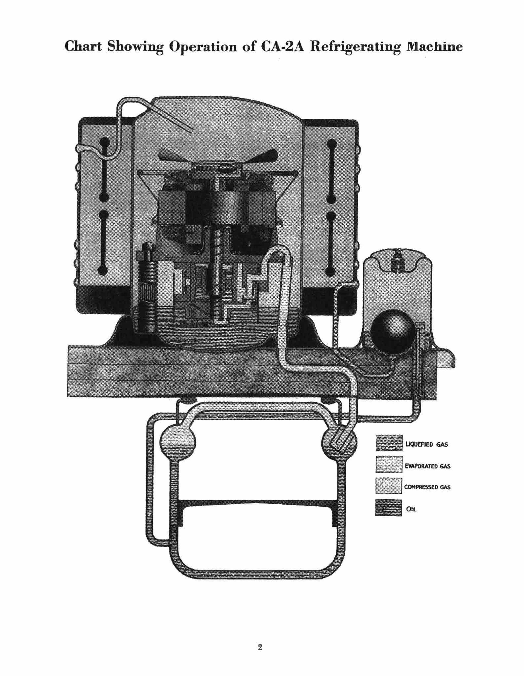
Chart Showing Operation of CA·2A Refrigerating Machine
2
, -.,--_ .. .. _,._-~-.,~ .. ---.-~ - '---
•
UQUEFIED GAS
OIL
,
HT47, HX.47, HT·70, HX·70, X.5, X.7 and T·7
DESCRIPTION
Refrigerating Machine (Models CA..IA., CA..2A., CA.-IB, and CA.-2B)
. This refrigerating machine is of Monitor Top design and construction. It is hermetically sealed. It is designed for efficient, quiet and troubl ... free perform· ance, and constructed for long life. A Glyptal.baked enamel, developed by the General Electric labora· tories, offers..,-a finish of unusual gloss and permanence.
Rejrigimml The refrigerant is methyl formate developed for
this use by the · General Electric lahoratories. It is a low pressure refrigerant with a boiling point of 880 F. at atmospheric pressure.
Temp. a F.
150 140 130 120 110 100 90 88
Pressure-Temperature Table for M'ethyl Formate
Preaaur~ lhs. per Temp. • of . .eq. In .. gauge
30.7 80 23.9 70 17.9 60 12.2 50 7.6 40 3.8 30 0.5 20
0 10 0
Compreuor
Vacuum, in. of-m'e1'Cury
5.5 10.2 14.5 17.8 20.4 22.7 24.5 25.9 27.0
The compressor is located on the high pressure side of the system. It i. of the oscillating type, de· veloped especially to handle this new refrigerant. The movable element, the oscillator, is actuated by an eccentric on the vertical shaft It oscillates rather than rotates, being keyed to the cylinder by a sliding blade. The compressor is spring mounted within the steel case and is carefully balanced 80 that no vibration is transmitted to the exterior. Oil under pressure lubricates every moving p •• rt.
Motor The motor is mounted directly ahove the compres·
sor on the vertical shaft. It operates as a resistance split· phase induction motor during starting and as a single-phase induction motor during normal running. The proper resistance is incorporated.in the starting winding so that an external resistor is not needed.
S_t.ing Relay The starting relay used to make and break the
starting winding circuit is located on the left rear
3
corner of the box top on the Form A machines. On the Form B units, it is mounted ou the condenser on the left rear side. These relays are simple in construction and practically noiseless in operation. The arma. ture settings are different since the armature in the relay used on Form A machines operates vertically. and 'on the Form B, it operates horizontally.
Conde ... "r The condensers are of smooth construction, made
possible by the use of a low~pressure refrigerant and General Electric developments in the control of automatic electric line welding equipment. The Form B condenser has a smoother appearance with six refrigerant passes, while the Form A had ten evenly spaced passes.
Flolll Yal"" A float valve, similar in construction to that used
on previous General Electric refrigerating machines, is located on the high pressure side of the system. On the Form A machine, it can be seen on the right rear corner of the box top, but on the Form B, it is located at the rear of the machine, out of sight from the front.
Cooling Un/I
The cooling unit is made of stainless steel. The CA·2A and CA·2B models have an aluminum freezing shelf. The surfaces are smooth, easy to clean and sanitary. The _ cooling unit is constructed to incorporate forced circulation of the refrigerant, thus assuring the highest cooling efficiency.
Control
The Form A machines have the control located on the front of the machine in the box top. On the Form B. the control is in the front center of the condenser, behind the condenser surface,. except for the two knobs which project through the condenser and the round chromium plated escutcheon plate. . .
Included in the control are a manual switch for turning the machine on or off, an adjustable automatic mechanism for regulating the cooling nnjt and cabinet air temperatures, a device for protecting the motor from ab:p.or~al load or power conditions, and an arrangement for defrosting the cooling unit.
'The Form A defrost mechanism is semi-automatic and in the Form B control, the machine is auto~ matically returned to normal operation after defrost· ing has been completed. Also, the range of average temperaPu'e5 hetw~n positions 1 and 9 is increased in the control used on Form B machines.

Cab; .... ,
A. Model HT-47-Poreelain enamel paneled- ex· letior. CA·IA unit.
Model lJX.47 Glyptal·baked ena"",l exterior. CA·IA unil.
Model X·5-Glyptal.baked enamel exterior. CA·IB unit.
These cabinets are of all·sleel constructi"n with one:piece aCid-resistant porcelain enamel interiors. New semi·conceale"d hing<:s and simple fingertip handle latch .. further enhance the appearance of the cabinets. Texlolite door slrips introduced by Gen· eralElcclric and proved for insulating quality and long life are used.
Model X·5 has the inletior cabinet light and the foot·pedal door opener. .
B. Model HT·7Oc-Por.celain enamel paneled ex· . lerior. CA·2A unit.
Model HX·7Oc-Glyplal.baked enamel exterior. CA·2A unit.
Model T·7-Poreelain enamel paneled exlerior. CA·2B unit.
Model X·7-G1yptal·baked enamel exlerior. CA·2B unit.
These cabinets are of a1hteel construction with onepiec.e acid-resIstant porcelain enamel interiors. New semi.concealed binges and .imple fingertip handle lalch .. further enhance the appearance of the cab· inets. Textolite door strips introduced by General Electric and proved for . l,,"dating quality and long life are usea. Sliding lIhelves with ·the new feature of adjustable shelf s!,acing ~e introduc~. The £60t· pedal door opener lS an aaded convemenee. Auto· matic lighting of the cabitie~in~ri6rs occurs a8 800n as the cabinet doors are opened.
Acoo .. orle. . .
A. For HT47, HX47, HX·70, X·5 and X·7 Re· frigerators.
The,e models are completelyeqnipped with en· ameled vegetable pan,· gla" chiller tray and alumi· num ice freezing pan. willt the General Electric lap. ered dividers for faster freezing and easier removal of ice cubes. A unit cord with a 'pecial locking con· ne~or which prcven!B aooido;ntal pul~ off,. yet !s easdy detachable WIth a slight turnmg motion, IS
included. The X·5 and X·7 models have an ice tray . lifter
included, and Ibe X·7 is equipped with one rubber ice freezing tray.
B. For HT·70 and T·7 Refrigeralors. Thi. model i6 completely equipped with cov·
ered glass food containers, enameled vegetable pan, wire fruit bosket, glass chiller tray, aluminum ice freezing pans with the General Electric tapered di· viders for faster freezing and easier removal of ice cubes, and a rubber ice tray. A special cord with snitable connectors for the unit and cabinet is in· eluded- The connector to the unit is of new locking construction, preventing accidOIltal pulling off, yet ea.it y detachable with a slight turning motion.
The T·7 is also equipped with an ice tray lifter.
4
GUllrantee
The early CA Form A machines carry a standard one·year warranty with an additional three-year servo ice contract on the sealed mechanism. After Oct. 10, 1933,. the Form A machines and all the Form B rna· chines have the on_e-rear warranty with a four-year replacement contract on the sealed mechanism.
Cycle of Operation When the manual switch of the control is turned to
the "on" position, an electric circuit is. completed to the running winding of tbe motor. The currenl /low· ing is of such a value ibat as it p..... through a coil in the starting relay in seri .. with the running winding, an armature is raised and a pair of contacts are ' closed, puttiug .the starting winding in parallel with· the niimipg wmdirig. The motor starts immediate1y. As soon as it- coriies· up· to speed, the current decl68ses, and the armafUre ~rops, breaking the 8tarting winding circuit. The. motor continues to · run 85 a single-phase ·indu·ction motor.
The compressor i. mounted directly below the motor on the vertical shafL The cylinder is circular in form 'and is concentric with the center of the shaft. The oscillato. of the c"mpreasor i. cylindrical ' in (orm and is mounted on the eccentric of the shaft. Tho oscillator is keyed 10 the cylinder so that it oscil· lates bUI does not rotate, f9llowing around tbe cylin· der wall as the sbaft rotates.
On the suction side of the oscillator, gas refriger. ant Qf low density is drawn into tbe compressor from the cooling unit. This g" is cQmpressed and then expelled through the discharge valve. Afler p.asing through an acoustic muliler, it is discharged into tbe compressor case.
Gas refriger~t (rom the cQ.mpressor caM passes through the conden,er where it is cooled and lique· fied. The liqnid refrigerant is Collected in the /loat valve and returned to the cooling unit. It is introduced through specially designed nozzles near the bottom of the cooling unit so that forced circulation of the liquid refrigerant i. secured.
The liquid refrigerant in the cooling unit evapo· ratea because of the reduced Jlre&8ure caused by the suction· from the compressor. In so evaporating, heat is absorbed through the cooling unit walla from the air· in contact with .them and from water contained in the ice trays within the cooling unit. Thus refrig. eration is obtained.
Unloading In order to keep the load Qn Ihe motor during the
starting period as low as po .. ible, it is desirable that the pressure of the refrigeranl on the suction and dis· charge sides of the compressor be the .ame. The process of equalizing this pressure is known as unloading.
Although the presaure within the compressor sbould be equalized, it is imperative that the higher pressure and warmer gaa refrigerant does nol leak back into the cooling unit to warm the liquid refrigerant there and thus 10 .. part of the refrigeration obtained during the operating period of the machine. The cooling unit i ... aled off from the compressor by meers of a check valve at the time of unloading.

•
The unloader valve on this model consists of 8
plunger in a housing mounted on top of the shaft. The centrifugal force on the plunger during normal running operation is such that it overcomes the tension of a spring; the plunger llies out and closes an opening in the bousing, wbich is subject to the pressure of the gas refrigerant in the compressor case. When the electric circuit to-the motor is opened, the motor slows doWD_ As it does· so, the centrifugal force on the plunger is reduced. until the spring draws the plunger back, thus opening tbehole in the housing.
When the unloader plunger opens, high pressure
gas refrigerant Hows through passages in the housing, down a hole drilled through the center of the shaft, through another hole in the bottom plate, and up into the check valve chamber in the cylinder wall. The pressure lifts and holds a small disc check valve against the check valve scat. Some of the gas re-. frigerant passes into the suction side of the compres· sorand thus accomplishes the unloading.
Since the unloading takes place early in the slowing up p'eriod, there is no vibration of the machine during Sf9pping. Furthermore, the machine can he started again imm..pately after it is stopped .
•• • • •
. , - . . CA .. 2A" Mach.ine;-O'l HT-70-CUbinet
5

•
" , ' . . CA.IA Retrlc .... tlna Maclilne
6

•
CA.IB Rolrill ... tI ... Mathlne
, CA-2B Rolri.erotlnal M.eh!ne ,
7

,
to .!Od ..... amtS'ald N.Oj
jO ",ddns ~" ,~
S~!l
'P"W
II
apA:) .I()983.JdwO'J JO S<IIliVlS lUa.lalna
, 1: pitS't~Jcfwo" ~JOW fiu!~~!..odtJII '!4..l
----......
til 6u.wO? •• .-..dOlo amt.aJd MOl jD fitdej'ns "'''N
:,lUlqaUJ-\I: VZ"V::> JO uOl1:)n.q91lo:)
I J~pu!ll;, OW! UM'D.ip 1/ .IOIh)A ~JV\f' J0-lDW .amss.uo ~ UO '~lU~Y.)3 ~
.9PU!IM Ifl~ ~,!d JO ~~~ lll!Od
~trl'Dqll3
,
,
,
ADJUSTMENTS
Description of Control, and Instructions for Replacing
Control The control is completely sealed. There are no
internal adjustments that can be made. Directions for operating the control are engraved on the es· cutcheon plate covering the control. Further ex· planation of these directions and the details of what happens within the control follow.
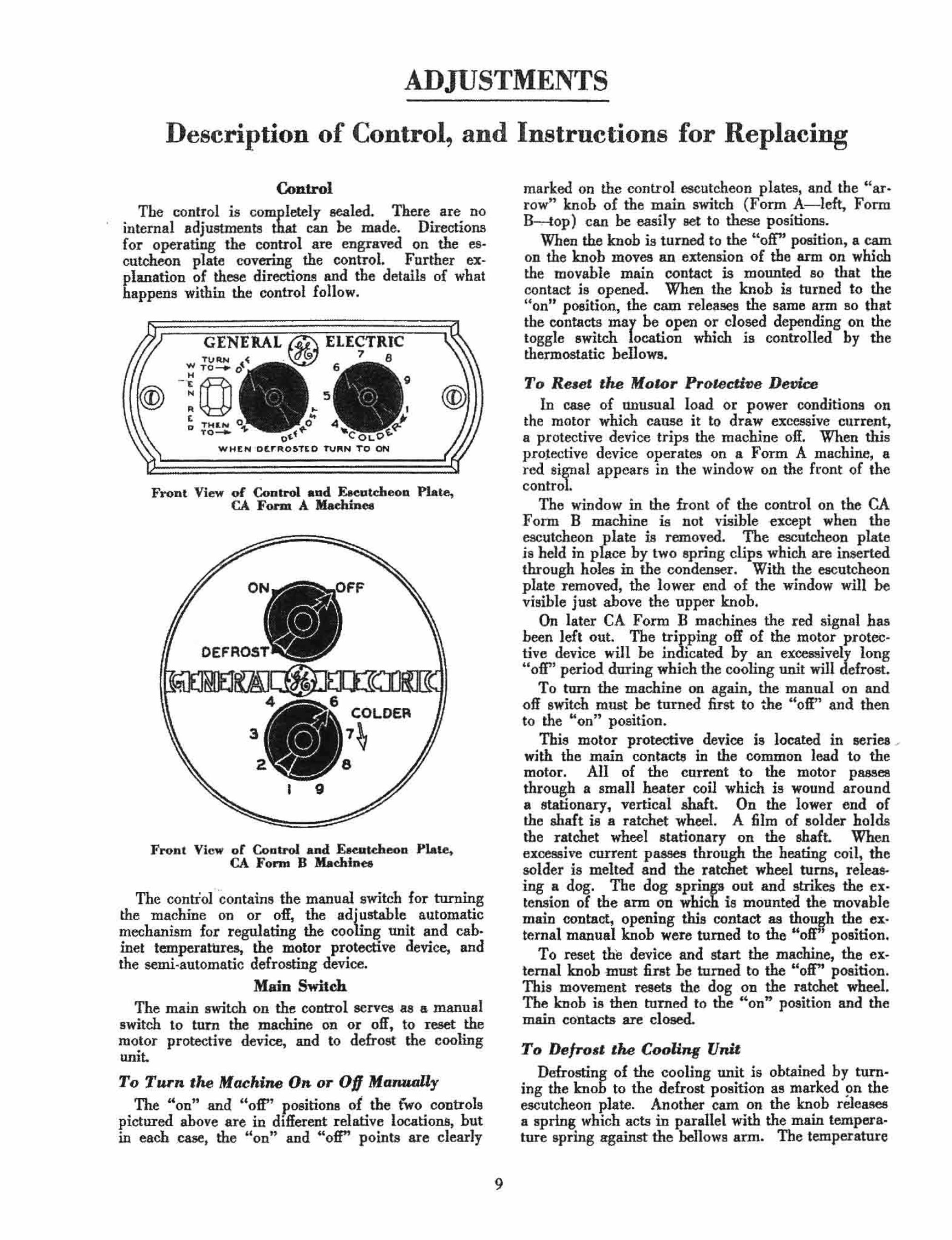
Front View of Control and FAeotdteoD Plate, CA FoJ'Dl A Maehinee
COLDER
~
Front View of Control and E.eutdu~on Plate, CA Form B Maehtnea
The contioI"contains the manual switch for turuing the machine on or off, the ad{t:lable automatic mechanism for regulating the coo' g unit and cab. inet temperatures, the motor protective device, and the semi-automatic defrosting device.
Main Switch The main switch on the control serves as 8- manual
switch to lurn the machine on or off, to reset the motor protective device, and to defrost the cooling
• umL
To Turn ,he Machine 0 .. or Of} ManuaUy The "on" and "oft" positions of the iwo controls
pictured above are in different relative locations, but in each ,case, the "on" and "off" points are clearly
9
marked on the control escutcheon plates, and the "ar· row" knob of the IDain switch (Form A- left, Form B , top) can be easily set to these positions.
When the knob is turned to the "off" position, a cam on the knob moves an extension of the ann on which the movable main contact is mounted so that the contact is opened. When the knob is turned to the "on" position, the cnm releases the same ann so that the contacts may be open or closed depending on the toggle switch location which is controlled by the thermostatic bellowa.
To Relet the Motor Prolecti"e Device In case of unusual load or power conditions on
the motor which cause it to draw excessive current, a protective device trips the machine oil. When this p.rotective device operates on a Form A machine, a red signal appears in the window on the front of the control.
The window in the front of the control on the CA Form B machine is not visible except when the escutcheon plate is removed. The escutcheon plate is held in place by two spring clip. which are inserted through holes in the condenser. With the escutcheon plate removed. the lower end of the window will be visible just above the upper knob.
On later CA Form B machines the red signal has been left out. The tripping off of the motor proteCtive device will be indicated by an excessively long "off" period during which the cooling ,lInit will defrost.
To turn the machine on again, the manual on and off switch must be turned first to the "oft" and then
th "" '. to e on posltion. This motor protective device is located in series ....
with the main contacts in the common lead to the motor. All of the current to the motor pass .. through a small heater coil which is wound around a stationary, vertical shaft. On the lower end of the shaft i. a ratchet wheel. A film of solder holds the ratchet wheel stationary on the shaft. When excessive current pll$SeS through the heating coil, the solder i. melted and the ratc1iet wheel turns, releasing a dog. The dog springs out and strikes the ex· tension of the arm on ·which is mounted the movable main contact, opening this contact as though the ex· ternal manual knob were turned to the "off" positron.
To reset the device -and .tart the machine, the external knob must first be turned to the "off" position. This movement resets the dog on the ratchet wheel. The knob is then turned to the "on" position and the main contacts are closed.
To DeJrod the Cooling Unit Defrosting of the cooling unit is obtained by turn
ing the knob to the defrost position as marked on the escutcheon plate. Another cam on the knob rOlea ... a spring which acts in parallel with the main temperature spring against the bellows arm. The temperature

range on the CA·2A _ cooling unit is -changed from 13.5' - 22' F. to 13.5' - 46' F. It is evident that defrosting will takepl.ace since" the cooling unit now operates on a defrosting cycle. After defrosting aCA Form A unit, the main switch should be turned
h "" " to t e on' pOsItiOn. The mechanism .for defrosting the cooling unjt of
the CA Form. B machine operates in the same manner in the contTol as for the CA Form A machine except that the CA Form B machine is automatically returned to normal operation after a single defrosting cycle. The CA Form A machine continues to operate through defrosting cycles until the knob is manually returned ~6 th~ normal "on" position.
The automatic return to normal operation after defrosting the CA Fonn B machine is accomplished by having an arm trip the cam On the m-ain switch which releases the auxiliary defrosting spring when the bellows.expands to the point corre~onding to the upper defrosting temperature limit. There is a spring in the main switch which snaps it back to the' on" po· . . .
slhon.
Temperature Knob
The temperature knob on the control allows adjust· ment of the temperature range of the cooling unit and the cabinet air to satisfy the· desires of the user ~ The movement of the knob ch8:nges the compression of the main temperature spring acting against the bellows arm.
The normal setting of the temperature knob is at position 5. The cooling unit temperature range, as measured in the bottom of the cooling unitt is approximately 13.5' - 22' F. for CA-2A units and 10' - 20' F. for CA-IA unit. at this control setling. The larger the number of the control setting, the colder the cooling unit will run and hence the cabinet will be colder. Form A machines have a range of average cooling unit bottom temperatures of about 10° F. between positions 1 and 9. This range is increased to 18° F. on the Form B units.
With the coutrol set on position 5 (normal) the cahinet air temperature in a room varying between 70' F. and 80. F. with a normal amount of food in the cabinet, will be in the vicinity of 38° F. to 42° F.
Directions for Removing and Installing a Control
The <:atalog numbers of controls used on the rna· chines when originally manufactured are given below: Form A Machine (lIO-volt, 60 cycle A-c.) .. 58 x 25 Form A Machine (l1O-volt, 50 cycle A·c.) .. 58 x 58 Form B Machine (nO-volt, 60 cyCle A-c.) •. 58 x 117 Form B Machine InO·volt, 50 cycle A·c.) .. 58 x 120
For replacement purposes Cat. No. MIA181 Uni· versal Replacement Control is furnished. This one control can be used on all type CA Machines regardless of Form or power supply. In order to ohtain the same temperature limits as with the original control, this replacement control must be set three control posi. tions warmer. Installation of the Universal Control is the same as for the original controls.
To Remove the Control CA. Form A Machine. 1. ' ooosen the clamp holding the bellows tube to
the left side of the cooling unit at the rear.
10
2. Remove and straighten the bellows tube. 3. Remove the two screws on the front of the
control holding it to the cabinet top.
4. Pull the control directly forward, guiding the bellows tube through the rubber bushing in the bottom plate. The rubber bushing may cling to the bellows tube. and pull up through the cahinet top. It should be teplaced. .
5. As Boon as the control hody is out of the cahinet top. the locking connector to the back of the control should be removed with a slight turning motion. . .
Caution: The locking connector to the back of the control is similar to that on. the conn.ecting cord to tM relay. II cannot b. removed by straight pulling. II must be tumed slightly.
6. The control can now be completely removed.
To Install a Control CA Form A Machines 1. Insert the end of the control tube through the
control opening in the cabinet top, push it through the box top insulation and start it through_ the rubber bushing in the bottom plate.
2. Guide the control tube througb the rubber bushing.
3. Connect the locking connector to the prongs On the back of the conlrol before the control enters the opening in the cabinet top.
4. Push the control into place and attach it with the two screws in the front.
5. Bend the bellows tube. into place and clamp it to the cooling unit. The upper end of the pinch off of the bellows tube should project just below thc clamp so that the liquid will he right under the clamp. The bellows tube at this point should be right against the rear cooling unit channel.
Caution:TM controt tube should not touch 1M cooling un.it header. 1/ it does, the temperature limits mar vary somewh.at I rom the proper ones.
6. The temperature knob should be set at position 5 if normal operating limits under normal operating conditions are desired.
CA. Form B Machines
When removing or instaI1ing a control on a CA Form B machine, the same instructions can be followed as for the Form A. However, since the control is mounted on the condenser, there are a few added steps.
The control escutcheon plate must he removed when working with the control. It is held in place by two spring clips which are inserted through holes in the condenser.
The control is mounted to the condenser by means of a bracket. Two screw, hold the bracket to the condenser and one screw holds the (:ontrol.
The CA·IB machine requires a longer bellows tube than the CA·2B machine. Since the same control is used for both machines, it will he found that the tube is too long for a CA-2B unit. The extra length can be taken up by putting a bend in the tube just after
•

,
.,
,
,
•
it comr .. throu~h the bottom plate. This bend should be made so that it will not interfere when placing things in the refrigerator.
Directions for Replacing the Control BeUows 1. Remove the control from the machine. 2. Lay the control on a flat working surface with
the seal cover uppermost. Remove the two bra •• screws which hold the bellows cover plate to the control and withdraw the bellows from the control.
Cal-Ition: After these 'wo screws are loosenetJ, and until the new beUotos is tightened into place) the control should not be moved violentlr or chan.ged from the position specified, otherwise, one of the taps which receive the attiJching screws mar ~lip out of the slot, and 1nay be lost inside 0/ the mechan~m.
3. Before the clamp which holds the replacement bellows during shif.ment can be removed the bulb must be coo ed down to - 10' F., and the bulb must be kept at this temperature until the bellows has been inserted into the control andlastened in place.
Place the bellows control tube into a con· tainer filled with dry ice. When the tempera· ture of the bulb has been reduced below - 10' F., the bellows will contract sufficiently to allow the shipping clamp to be removed.
Caution: Be sure not to loosen the nut which locks the cover plate to the beUows. In straight. ening or bending the bellows tube, avoid bend· ing the section near the silver soldered joint where it joins the bellows. A strain at this poi~ mar crack the tubing.
4. Insert the bellows, carefully observing the caution under item 3. Be careful to keep the-
bellows tube cold until the attaching screws are firmly tightened.
Caution: Be sure that the cupped fiber washer is properly in place between the beUows and b,eUows. ann. The belum}~ arm i.s an. electrically lwe pomt, and must be msuIated from the bel· lows to avoid grounding the motor circuit to ,he cooling unit.
S. After the control has been teplaced on tbe rna· chine be sure to check. the operation of the control and the telIl.perature limits on the cool~ iilg unit to see that the control is· functioning properly.
To Reset the Te"'l'erature Control
L Disconnect the refrige.l"8tor connecting cord from the wall outlet. This is necessary· since the screw holding the control knob is at the same electric potential as the movRble main contact.
2. Remove the sealing plug from the center of the knob, using a pocket !cnile.
3. Take out the small screw in the center of the knob.
Caution: Do not push inU1.ard on the spindle Ie which t/o" knob is a"ached. J f the spindle is pruhed in, a .mall bearing piece may fallout and damage Ihe conlrol.
4, Reset the knob in a Clockwise direction to obtain warmer temperatures and count&~clockwi8e for colder temperatures. The cabinet air temperature is changed about 10 F. betW6CQ suc~ive numbers on the dial.
5. Replace the knob screw and · sealing plug, reo membering not to push the knob $pindle inward.
Description of Starting Relay, and Instructions for Replacing Slarting Relay
. The starting relay, located on the left-rear corner
of the cabinet top on the CA Form A machines, and on the rear of the condenser on the CA Form B machines, contains a coil in series with the running . winding which, when the machine is started, lifts an armature and closes a pair of electrical contacts. Closing these contacts puts the starting winding of the motor in parallel with the running winding. The motor then starts. As soon as the motor is up to speed, the current in the running winding circuit drops to such a yalue that the armature drops and breaks the starting winding circuit. The motor continues to run single pha.e with current in the running winding only.
The lifting of the armature during starting is caused by the repelling force between the coil and the armature itself which fonns a single short-circuited turn circuit above the coil. The armature is held steady in the upper position by the small steel bars under the short·circuited turn whicb tend to stay in tbe magnetic field between the pole pieces. When the current. through the coil decreases .to a predetermined
11
'alue, the armature drop. suddenly, giving the de· sired snap action to the electrical contactS .
Directions for Removing and Inslal1ing a Starting Relay
The catalog numbers of relays used on the machines when originally manufact~l"ed are given below:
Form A (nO.volt, 60 cycle A.c.) ... 58x 14 Form A (nO-volt, 50 cycle A.c.) ••. 58 x 59 Form B (UO-volt, 60 cycle A.c.) •.• 58 x 121 Form B (nO-volt, 50 cyele A-c.) ..• 58 x 122
These original relays should not be interebanp;ed either between Form A and Form B machines or be· tween 50 and 60 cycle machines.
For the replacement of starting relays on all CA machines, the later design, Cat. No. MIA162, starting relay is furnished. This is a CR·IOS7 type R relay with an automatic reset overload device incorporated in it. The automatic reset overload wiB function hefore the overload in the control 80 there should be no trouble because of the two overload devices in the
•
circuit. On 50 cycle BeJ;'vice, the overload may trip a few times during pull.down in a very warm room, but it 'will inimedi8te~y reset and operati~n will continue.
Install$tion of the Type R starting relay requires special aecelJSOr~es. Dir~ioJ:ls fo.r replacing the start· ing relay with both the original style and the Type R are given below.
Ca~tio.1l:: . Do not disturb QT adjust rite slarting . . armature.-
The artn4lure of the starling relay u qarelully con· structed and tested at the lactory in order thot its tenJion be just righ! to insure prqper 3Mrtlifg 01 the mac"ine. (;o!l.$equently, the slarting relay 'u .. akd (mil. mllst not be .opened ·unle .. absolutelY ,.,necessary.
If it u lound nec()Jsary 10 open a starling relay OJ
a last re3ort _.bftjot:e replacing a mtJChine, great . care must be· used.
Never interchange any motor leads. The starting winding will burn 'in a short time if left continuousl" in the circuit. .
In .some instances, the color of the leads to the relay may not be easily distinguuhoble. II such
. u ' t/l" case, mark U&em carefully w/l(1n changing :fJ starling relay. , ...
To RfimOt>e 'he Relay
1. .D~sconnect the locking connector from the back . of. the relay, using .s :.Hght turning motion.
2,Bi:';"k the seal on .the hick o( the relay and reo ·~'move the cover. .
3. Disconnect all leads, marking any lead whose color is not easily recognized.
4. Remove the two &Crews holding the relay to the (~hinet top of the Forln A machines or the condenser of the Form B machines.
To 1".taU an Original Style Relay
1. Reverse the procec:lure for removing a relay, maldllg sure that the Sber washers are placed under the corners of the relay in order to pre· vent warpage of the baae.
To l,..taU a Type R Replacement Relay
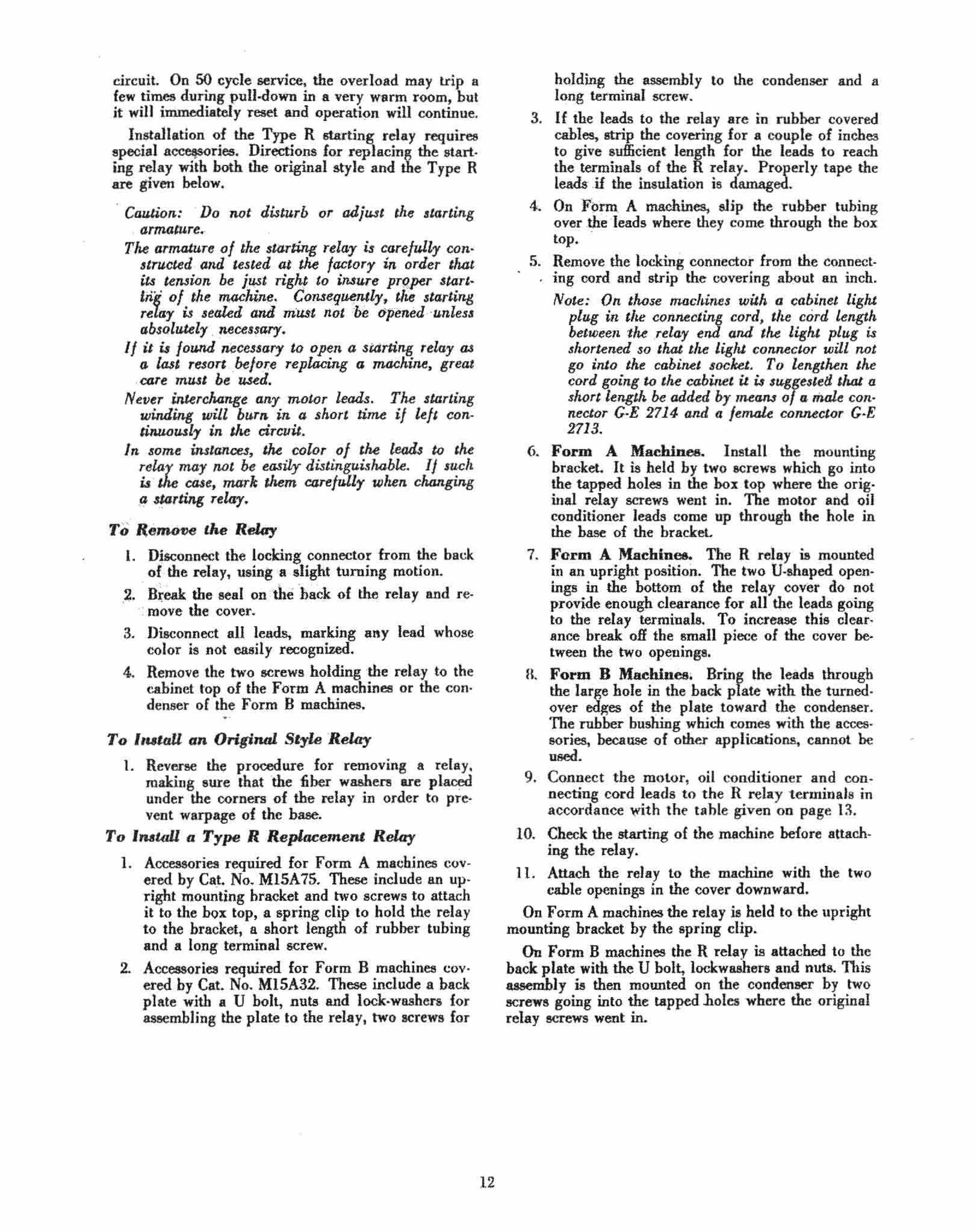
1. Accessories required for Form A ma(.:hines covered by Ca.!. No. M15A 75. These include an up· right mounting bracket and two screws to attach it to the box top, a spring clip to hold the relay to the br.cket, a short length of rubber tubing and a long terminal screw.
2. Accessories required for Form B machines covered by Cat. No. M15A32. These include a b.ck plate with a U bolt, nuts and lock· washers (or .... mbling the plate to the relay, two screws for
12
holding the ~ssembly to the condenser and a l~ng terminal screw.
3. If the leads to the relay are in rubber covered cables, stJjp the covering lor a couple of inches to give sufficient length for the leads to reach the terminals of the R relay. Properly tape the leads' U the insulation is damaged.
4. On Form. A machines, slip the rubber tubing overthideads where they come through the box top.
5. Remove the locking connector from the connect· . ing cord and strip the covering about an inch.
Note: On those machines with a cabinet light plug in. ·the connec'ting cord, the cord length belwe.n the .re/ay end and lhe lighl plug is shortened so that the light. connector will not go into the cabinet socket. To lengthen the cord going 10 the cabinet it ;., suggested UW a short length he added by 'ReaM of a mal. con· nectar G·E 2714 and a lemule connector G·E 2713. '
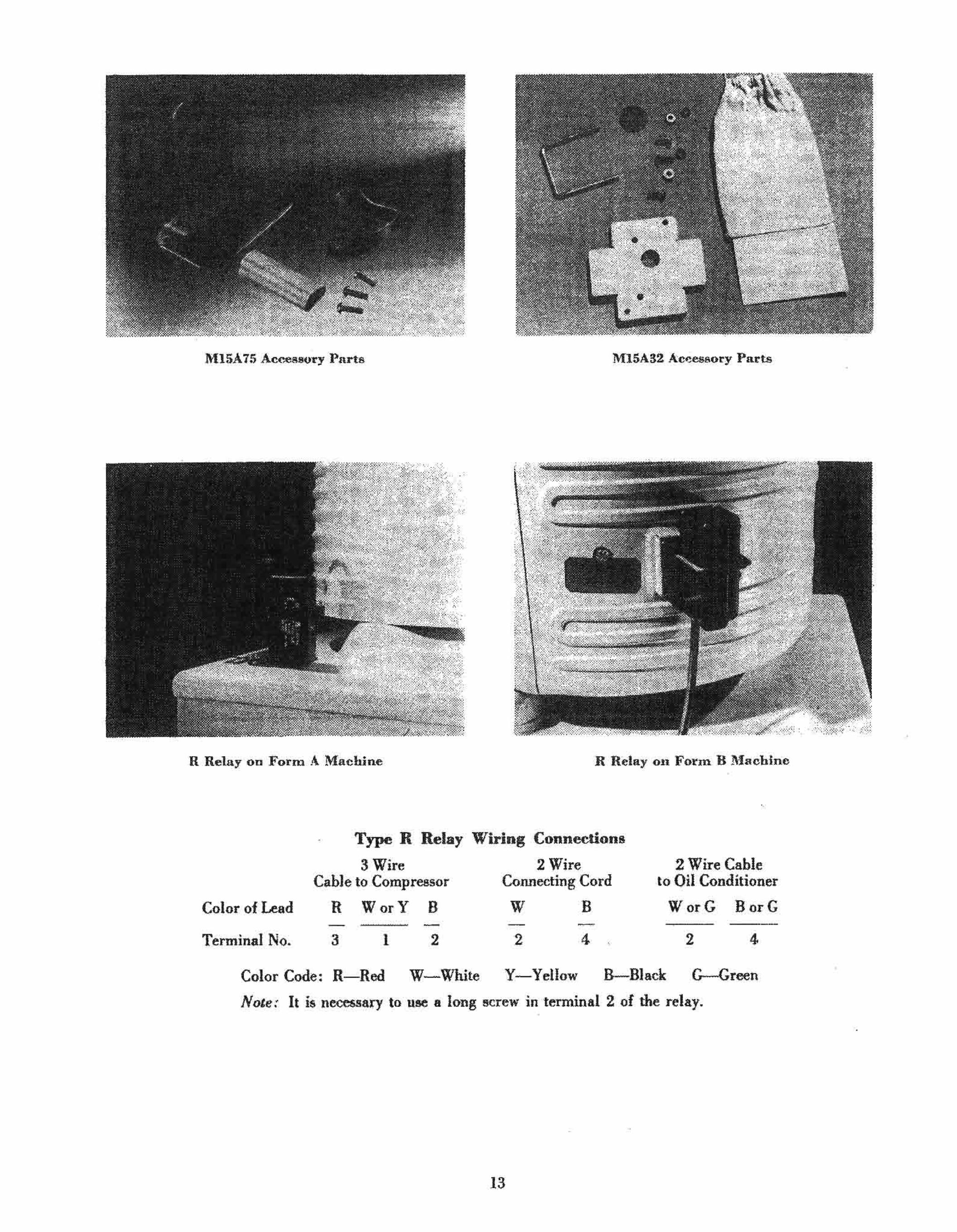
6. Form A Machin"", Install the mounting bracket. It is held by two screws which go into the tapped holes in the box top where the orig. inal relay screws went in. The motor and oil conditioner leads come up througb the hole in the base of the bracket.
7. Form A Machin ... , The R relay is mounted in an upright position. The two U;sh.ped open· ings in the bottom of the rel .. y cover do not
. provide enough clearance for all the leads going to the relay terminals. .To increase this dearance· hreak off thesman piece of the cover be· tween the two openings. '.
n. Form B Machines" Bring the leads through the large hole in the back plate with the turned· over edges of the plate toward the condenser. 'The rubber bushing which comes with the acces· sories, because of other applications, cannot be used.
9. Connect the motor, oil conditioner and con· neeting cord 1eads to the R relay terminals in accordance with the tahle given on page 13.
10. Check the starting of the machine before attach. ing the relay.
II. Attach the relay to the machine with the two cable openings in the cover downward.
On Form A machines the rel.y is held to the upright mounting bracket by the spring clip.
On Form B machines the R relav is attached to the bock plate with the U bolt, lockw.shers and nuts. This ...embly is then mounted on tbe condenser by two screws going into the tapped .boles where the original relay screws went in.
M15A75 Acces8()'l'Y Parts MlSA32 Acieesaory Purts
R Relay on Form A M'achine R Relay on Form B Machine
Tn>e R Relay Wiring Conneclion.
3 Wire 2 Wire 2 Wire Cable Cable to Compressor Connecting Cord to Oil Conditioner
Color of Lead R WarY B W B WorG BorG - - -
Terminal No. 3 I 2 2 4 2 4
Color Code: R-Red W-White Y-Yellow B Black G-Green
Note: It is necessary to use a long screw in terminal 2 of the relay.
13
Machine Adjustments
I.. MACHINE DOES .NOT RUN PROPERLY
Syml'tom8
The refrigerat~ng machine m4Y have' one or more of the following 8ymptoms:
1. Stalled (will not stan pr run at aU). 2. Starts and rUils only "'ith both windings in the
.circuit. 3. Burned motor. 4. WjU not restart after shuttillg olf. S. Motor profecn'Ve ·d~yice trips off. 6. R~na .all the rune (does llot shut off).
Adjustment8
The source of trouble may be external to the rna· chine or it may be in the machine itself. It is rec· ommended that the external factors be checked first These include sueb things as the location of the ma· chine, the current and voltage to the machine, and the electrical circuit to the machine. In testing the machine, it is suggested that the parts be checked in ~e. foU~wing ord,er,: contrQI, .sl,8r~ing relay, oil conditioner and finally ·the machme ltself.
. 1. Stl!lled (WUl Dol start or run al aU)
. l( the machine Will riOt start or run at all, the pos· sjble causes are: ' .
A • . Improper cu1")"ent" or voltage. B; Restricted air ' circulation to condenser. C. Open circuit. D. Grriunded circuit E. Short circuit F. Non·condensable gas. G. StaI\ed eompressor. H. Excessive load 'On compressor.
•
.4.. Improper Current or V oftQge The machine is designed for operation on 6Q..cycle
alternating current. It win also operate satisfactorily on 50-cycle alternating current jf a special control and relay are used.
The machine will not operate on 25 or 4O.cycle alternating current, or on direct current.
While the rated voltage on the machine is 110 volts, it will operate satisfactorily on any voltage between 100 and 135.
When the voltage at the machine at the time of starting is less than 100 volts and the machine is operating under heavy ' load conditions, it may not start and the motor protective device will trip off.
When the voltage is above 135 and the machine is . operating under heavy load conditions, the current to the motor may he sufficient to trip the motOr protective device.
B. Re"r/cled .4.ir Circulation to CondenBer If the circulation of air is restricted from the con
denser, the head pressure may rise to such a point that the machine may trip off or the compressor may stall.
14
It is recommended that at least one side of the machine be left exposed. The space above the rna· chine lOp should be at least six inches. If a machine is enclQ&ed mQre than this amount, ,it may· he necessary ,.to :provide .forced air circulation in order to obtain 8atisf8~tory operation.
C~ .. Open Circuit a. Circuit ·'0 1M refrigeraeor. .
Ch.eck the elcctri .. 1 circuit to the refrigerating ma· chin:e by placing a series test lamp across the termi· mds of the connecting cord connector and noting that it lights, or by observing that the house watt·hoor·meter moves when the machine. on which the control is turned to the "Off" p"osition, is connected to the circuit and all other appliances or lights are turned off, indio cating a circuit through the oil conditioner. For CA·2A and CA·2B machines it is possihle to ohserve whether the light in the cabinet comes on when the door is opened. If the cabinet light does not come on and the bulb tests all right in a socket on another electrical circuit. there is an open circuit in' ~ supply line. If an""open circuit is fOWld; check the cord con· nections to the machine and to the wall reCeptacle, making sure that good electrical contact is obtained . Also, check the supply line fuses. .
Check both of the lOcking connectors, · the one on the connecting eord whicl1 atta,ches Ii> the ' relay and the one which attaches to the c6ntiol; for possible
• • • • poor contact or open CIrCUIt·
One of the wires ·may have become diseonnected in the connector.
••
The spring contacts in .some connectors may not make contact, having lost their spring tension when the wires were soldered .
The oman brass screws which hold the fiber disc ' over the end of the connector may project out far enough to prevent the prongs on the relay from mak· ing contact with the spring contacts in the connector. Make sure that the. wires in the connector are properly located in the grooves so that they do not interfere with the .. ating of the disc.
b. ConlTol. If the circujt· to the refrigerator is all right. re
move the coutro) as described on page 10. Replace it with a new control. .If the machine starts and runs, it is evident that the origin a) control may have had an open circuit.
CtuUion: Before replacing a control, make Jur" lhae the machine is not in 1M "off" <>ycle. TM bellOWJ tube can be warmed by holding the hanJ over it Oft the cooling unit.
A control eon be tested for open circuit by placing a test lamp in sedes with the control in an electric circuit and observing whether the lamp lights when the main switch is turned to the "on" position. If the lamp does not light, there is an open circuit in the control.
,
•
,
,
An open circuit in a control may be caused by a weak bellows, open lead or connection, burned con· tacts, or defective toggle device. Since the control is sealed, it must he replaced as a whole. Part replacements cannot be made.
c. SINting relay. Caution: Do nol disturb or adjust the starting
ormolure. The armature of the s/6rti"{f relay is corefully constructed and tested at the factory in order that itJ tension be just right to insure proper SINting of the machine. Consequently, the .tarting relay is sealed and must oot be opened unless absolutely necessary.
If it i.t found necessary to open a starting relay as a lasl resort before replacing a machine, great caTe must be used.
Never interchange any motor leads. The starting winding will burn in a .hort time if left continuously in the circuit.
In .ome instances, the color 0/ the leads to the relay mar not be easily di.ttmguishable. J f such is the case, mark them carefully when changing a SINting ,e!Gr.
If the circuit to the refrigerator anti the control proves to be all right but stiU the machine does not start, the starting relay may be opened and inspected.
Check the electrieaf connections to the relay, making sure that all are tight and that tbe proper lead or leads come to each terminal. Refer to the electrical circuit diagram on page 37.
Raise the armature carefully , using a piece of in~ 8uJating material such as wood or cardboard. The armature should operate freely.
•
Caution: When ~aisecl. the armature is at line voltage so shaald not be Mndled. If a person', body is grounded, a serious shack might result.
1£ the starting contacts do not spark when the aI"p1ature is raised and lowered, there is an open circuit to the starting winding.
Note: The main switch of the control should be in the "on" position when this test and succeeding tests on the starting relay are made.
Disconnect the red (running) lead in the relay and see if it sparks when touched to its terminal. If it does not, there is an open circuit to the rwming wind. ing. Tbe open circuit may he in the series coil in the relay, in the running or common lead to the motor, or in the motor.
To test the series coil in the relay, short circuit it with a short piece of insulated wire between the terminal to which the single oil conditioner lead is connected and the terminal to whicb the ted lead is connected. Again see if the red lead sparks wben touched to its terminal. If it does but did not before the series coil was short circuited. there is an open circuit in the series coil. The rday must be replaced. Refer to page 12 for instructions for removing and replacing the relay.
IT there is evidence of open circuits to both the starting and running windings, check the common lead circuit by disconnecting botb the white (starting) and red (running) leads in tbe relay, placing a test Jamp in series with them in an electrical circuit
15
and observing if the lamp lights. If it does, the open circuit is in the common lead. If it does not, the open circuit may be in any two or all of the leads or in ~e IDotor. ~
d. Machine. If, from the tests conducted on the starting relay,
it is proved that there is an open circuit in the com· mon, running or starting circuits or in the motor which cannot be repaired, the machine must be replaced.
D. Grounded Cir""it AU electrical circuits and connections are iDSU~
lated from the refrigerating macbine itself. ·If one of the electrical circuits or connections should come in direct contact with a part of the refrigerating mao chine, it is considered grounded.
A ground in the circuit to the refrigerator, in the control, starting relay, oil conditioner, or machine may cause blowing of the bouse fuses, tripping off of the motor protective device, welding of the contacts or burning off of a lead.
A series test lamp will be found necessary to locate the ground.
Caution: The machine itself must not be grounded either through the cabinet or test rack while testing for a grounded circuitj otherwise, the line to the refrigerator may be shart cirqJited 10 ground.
If the machine can oot be conveniently insul.o.ted from ground, a .eries test lamp must be used in each lead from line to the machine.
a. Circuit to the refrigerator. A groOD? in the circuit to the r~frigerator . will
cause blowmg of the house fuses after the refngesatar is disconnected from the circuit.
Make sure that the ground is not in the cord connector or plug. Look for evidence of arcing. Also, watch for indications of moisture and dirt.
b. Control, starting relay, oil conditioner and -machine.
The control, starting relay, oil conditioner and machine can be tested as a group. Then, if a ground is found, each can he tested separaiely.
Refer to the above "Caution." Plug one terminal of the cord connector into one
prong in the back of the starting relay. Put one terminal of the test lamp into the other ,terminal of the connector. With the knob of the control in the "on" position, touch the other terminal of the lamp to the other prong in the back of the relay. The lamp should light, indicating a circuit through the motor.
Then touch this second ierIninal of the lamp to some un painted part of the machine such as the screw.: on the top of the Hoat valve or one of :the acrews balding the nameplate to the cabinet top. If ·the lamp lights, there is a ground, in which case proceed to locate it.
c. Control. Replace: the control with a new one. If the ma
chine starts and runs satisfactorily, there may have been a ground in the original control.

Ctwtion: If /he growuJ is in 1M starting relay, oil CQTr4i#!>rU:T or miiCliihe, ' the motor protective
. deiJiCe may trip off, 1M. main contacls may weld or a kad may be burned a If in the. new control.
A ground in the control can be verified by . plug· ging first one rrong of ·the control and then the other into a termiDa of the c~>rd connector which ordinarily i. attached to the .starting relay. Put a "'51 l8D1p in series hetweeQ the other" teI'iIlmal of the cord Connee· lor and the bellows ·tube. If the lamp lights, there is a ground in the contro!' .
Caulion: The contro.l or bellows tube """" not be grounded while tesling for a grounded circuit; olheTW~e, 1M line to 1M refrii;etalor may be short circuitedt" ground. •
d. Starting relay.
Caution: D~ 1Wt open the starting relay u~les~ . absolll.tely ""!,,,ssory. Refer 10 the "Cautwn'
under .. Startmg relay" on page 12.
If the 'grounded circuit is apparently in the start· ing relay, 'oil conditioner or machjne, it is permissi. ble to open the starting relay and inspect it
Make a visual inspection of all of the leads and connections. Watch for evidence of arcing.
Remove the two screws holding the relay and lift the relay a. far as the leads allow. Check to see that Ihe leads do not chafe each other or the cabinet top. Look to see that there is no evidence of arcing between he screw heads under the relay and the cabinet top.
Also, watch for indications of moisture and dirt under the relay.
If a groWlded spot i. found, eliminate it by taping or otherwise insulating it.
When replacing the relay, carefully follow the direction. on page 12. y
c. Oil conditioner.
Refer to the tfCautwnn under D on page Disconnect both oil conditioner lead. in
ing relay. Put one lead into a terminal of . . Put one terminal of the test lamp .
of the cord connector. Touch the other of the lamp Ie the second oil·' conditioner
The lamp abould light, indicatieg a circuit the oil conditioner:
Then touch the second terminal of the lamp to some unpainted part of the machine Buch as the screw on the top of the 1I0at valve or one of the screws hold· ing the nameplate to the cabinet top. If the lamp lighte, the oil conditioner i. grounded and abould be replaced. ,
" f. M~a.ine. Refer to the "Caution" under D on page 15.
Disconnect the red and white leads in th~\t.eJ;':y. Attach the red lead to 8 terminal of the ciifd':t,9h· nectar. Put one .tenninal of the test lap;q;'".ilI? the other connector terminal. Touch the other ,.tehninal of the lamp to the white lead. The lamp shottld light, indicating a circuit through the motor.
16
Then touch the second terminal of the lamp to some unpainted pBtt of the machine BUch 8S the screw on top of the 1I0at<>valve or otie of the screw. holding the nameplate to cabinet top. If the lamp lights, the machine is and should be replaced. .
E. Slwrl Cireult All electrical circuits and conn~tions are insu
lated from each other. If two of these circuits or connections should come in contact with each other. ., ~
a abort circuit results. . A short circuit in the circuit to the refrigerator or
in the oil conditioner may cause blowing of the house fu.... A short circuit in the relay may cause blow· , ing of the hou.e fuses, tripping .of the motor protec. tive device, welding or burning of .the starting contacts, or burning · off of a lead. A short circuit in the con.tIol may cause the machine to run all the time. A short circuit in the machine ·mAY cause blow· ing of the house fuses, tripping off of the motor pro· tecti~e device, welding o~ bur~iDg of ~~ main or starting contacts, or burrung· oft' of a lead.
a. Circuit 10 the refrigerator.
A sbort circuit in the circuit to the refrigerator will cause "blowing of the house fusea aCter the reo frigerator is di~onnected.
Make sure that the short circuit i. not in the cord connector or plug. Look fO{ evidence oC arcing; alao. indications of moisture or dirt.
b. Control. •
The machine will continue to Tun even when the main swjtch is turned to the '~off" position if there is a short circuit in· the control. Replace the co·ntrol.
c. Starting re14y. CaUlion: Do not 'open the .'tarting rewy unles.,
absolutely necessary. Refer to the "Caution}' under H Starting relay" 011. page 12.
abort circuit aeerna to be in the starting relay. . or machine, it is permissible to open relay and inspect it
a visual inspeCtion of all of the leads and noting that the leads are properly can·
. touChing. Look for .. vidence of arcing. :rv. the tenninals on the oil can·
ditioner . sure that the one attached to the terminal black (co"l"'on) motor lead ~oe. not tOllch . uprig?t po.t supporting the start· 109 armature. Should thIB happen, there would he a abort circuit as SOOIl .. the starting contacts cloSe.
Check the other oil conditioner terminal to see that it does not touch the red motor lead or its tenoina!. If it does, the series c~i1 will be left out of the cir· cuit, the machine will not start and the motor protec· tive device will trip off.
Remove the two screw. holding the relay to the cabinet top and lift the relay as far as the lead. allow. Check to see that the leads do not chafe each other or the cabinet top. Look for evidence of arc· ing. Inspect the under side of the relay. Watch for indications of moisture and dirt.

I
If a 6h()rt~circuited spot is found, eliminate it by taping or otherwise insulating it.
. When replacing the relay, carefully follow the directions on page 12. d. Oil coruJitioner.
Disconnect one of the oil conditioner leads in the 'starting relay and put· a series lamp in the circuit between the disconnected lead and its terminal. TUl'll
the main switch to the "ofP' position. If the oil con~ 'pitioner is short circuited, the lamp wil.l burn with normal brilliancy. If the oil conditioner is all right, the lamp will glow at reduced brilliancy.
e. MiUJrnne. .. If there is still Ii short circuit present after the
preceding tests have heen ' completedt · it" must he in the machine. In this case, the machine should be replaced.
F. Non-CoJldensabk Gas Any collection of non<>condensable gas in the float
may increase the head pressure sufficiently to cause the motor protective device to trip off or the compressol' to stall. . The non-condensable gas can be bled from the
float.lj'or symptoms ofnou·condensa'ble gas, and coro~ plete bleeding instruct.ions, refer to ttBleeding rn~ structions" under'*General AdjustmentsH on page 25.
G. Stalkd Compre.llOr The compressor may be stuck with · qprrosion, dirt .
or mechanical failure of a part. Jarr,!ll"g of the mao chine may free the compressor if ~ecause _ is of minor extent. \T .'. , ,
Apply 220 volts A.C. momentarilytRJpe machine; The compressor may be hroken looslicwith this treat· ment and then continue to ru.n ; _~Ati.~.£~torjly on Donnal voltage. Auto·transformer" 22().HO volts, . Cat. No. 9AC26A, used backwards, iS recOniIli~n<led · for obtaining the higher voltage if '220 "ii>li. A.C. power is not available. . " ' '''''; -'e - '.' ",y- . :-
- ,'. - ',
H. E",ceuive Load on ... ' ... f ,·.:
The compressor may stall
in the circuit until the motor protective device trips off. This condition is usually brought about by a defective electrical circuit or something that nearly stalls the compressor. With the exception of 8U
open circuit, the possible causes are similar to those for a stalled machine:
A. Improper current or voltage. B. Restricted air circulation to condenser . . c. Grounded circuit. D. Short circuit. E. Non-condensable gas. < . F. Hard ~llJlIl_i.~g compreSS9f. _, . G. EXOOSsiveI9~'d ' on _co~p.ress<?r~
• . • , . . • .• ' .. ', .. c- · -- .. . , . . . . . '.
Refer to ther;orre5pqndi.~g- .,sce:tiop,s. under. "Stalled (will not start Of run at all)" for the pl'Ocedure for locating and taking care of the trouble.
" 3. Burned Molor
A burned motor will be indicated by a discolora· tion of the machine case top. If a _machine with a burned motor is found, every effort should be made to determine the cause of burning and this information abould be included on the report.
4. Will Not Restart Afler Shulting Oft"
The machine will not restart for a period of time after shutting off in a cycle or being Shut off manually. The period of time may vary from a rew sec· onds to several minutes. If this time is longer than the "oft''' cycle, the motor protective device will trip off when the machine tries to start. If the time is less . than the "off" cycle, the motor protective · dev.ice does not t~ip off and the refrigeration is not im· pairedt then the condition-is not serious and docs not need attention. "
There are three possjble sources of trouble wh~n a machine will not restart afler shutting off:
A< Unloader stuck shut. B. Impr~per motor air gap. C. Partially weak bellows in conlrol.
. ~ _ ..
. ,'. '
A. Unloader Stuck Shut . . ,
If the nnloader plnng~r is stuck "hut, the machine will no~ unload, or restart again after shutting __ · off. The motor Jlrotective device may trip off when ,t;\>e machine tries to start. The action oJ the unloader
load on it, particularly during . , after the refrigerator is installed off for a tjrn:e. . At such times, . .ture is high and a COlosi, refrigerant may be in Ihe ditions tending to increase
,:-.: ' , te'an" lie ::lieard when the machine stops if it is operat-ing 0Prol!il!i!~ .
It is recommended that the the control main switch for o. a ~, £ew conneclor cord should be l.ft ~\",~~d to .. and the house electrical outlet , ~() ;ibat the. oll . ditioner will be in the circuit. Th¢'l!'fuid ie£dgerant in the base will be boiled oyt "fAne lub*~ting oil.
. ~' l ' '''~ _ . ..
It may be ~ecessa:y to res~\iir,he . m!!c;hille 1D?~·e than once if '.t contmues to. \f!P\ .oII whde(pul~g down. Mter It h~s reacheet nott)!a.l operall~g ",tem· peratures it will continue to [un all right. . . ,
2. Starls and Runs Only with Both Windings . . in the Cir.cuit
The machine may start and rim with both windings
<
S.tart an?,"s!.?P t4e ~m~chin,e .:,t. num~er of. times in rapld successiOn. < J"rrmg the machme IIDght also
... loosen t;\>e pll1;;ger. <. '\ d> _t
17
n. I';'pr;'per M.;t;;r Air Gap . It is possible iliat the machine will not restart after
shutting "II, yet the unloader operates all right. This condilion Usually occurs ~nly when tlj~ maphil!e is
~ti~~~:n:ir:aje::!r~,~~r!or;~~~~:,~~;~:;::~!_~: supply. The motor protecllve . devlcc ' may tnp .ojf. The trouble may not occur under lighter loads or with higher · voltage. The ecnditi~n responsible for ·this . . , . . IS an Improper motor au gap.
Cl>ecl\ the machine by running it continuously un· der h~avy load ~onditi~ns by putting pans. of hot water ni the coolIng Wllt and partly hlanketmg the condenser. Observe whether the machi~e restarts immediately after shutting off and. uuloading properly.
Jarring of the .maehine may shift the stator the ex· tremely small amount necessary to .rectify the defect. Otherwise, if the maehine trips off or stalls with this trouble, it should be «placed.
c. Partially If' eak Comrol Bellows If apparently the unit will not trip on again after
being off, it may be due· to partially weak control bellows. This would cause the 'teut on" point of. the control to be at a much higher temperature than normal, and the machine might remain off long enough to cause the coQIing unit to defrost.
For instructions on replacing the control bellows, refer ,to page 11 of the section on nControJ Adjust~ ments."
5.. Motor Protective Device Trips Off
The motor protective device operates whenever the current to the motor is excessive. It will trip off under any of the following conditions:
A. Improper current or voltage. B. Restricted air circul~tion to condenser. C. Open circuit to starting winding. D. Grounded circuit E. Short circuit. F. Machine . will !lot ,estart after shutting off. G. Non·condensable gas. H. Hard running or stalled compressor. I. Excessive load on compressor. J. Defective relay.
Refer to the previous ""ctions on "Stalled (will not run at all)" and "Will not restart after ahutting off. H
Tripping off may be cau""d by a defective relay as noted above in item rrJ.~9 The machine may operate normally for quite some time before the overJoad trips and yi,sual inspection reveals nothing wrong with either the machine or tbe relay. Usually, however, the starting contacts will he found too close together. To adjust a complaint of this nature, replace the starting relay as explained on page 12, and make no attempt to adjust the relay itself.
•
While the tripping off of the motor protective device will generally be an indication of trouble else· where, it is possible occasionally to find a control in which the motor protective device is faulty. If such is believed to he the case, it is recoll11Dended that the control be ehanged. If the new· control operates satisfactorily, it is evident that the original one may have been defective.
If absolutely necessary, a motor protective device can he checked by opening the starting relay and holding the starting arm up with a piece of insulating material such as wood or cardboard. The machine should he running. The motor protective device should trip off within % to 1* minutes.
Caution: When raised, Ille tJTmature is at line voltage so should not be lumdled. If a person's
18
Iwd"y is IJroullded, a serious shock might re.'~ult. Al.<;o, refer to the HCaUl.ion" under .nStarting relay" 011 page 11.
6. RuDS all the Tilne (Doe8 not Shill off) When a machine runs aU the time and fails to shut
off, the cause is either unsatisfactory refrigeration or defective control operaiio~. If it is the 'former, refer to Section II, "Unsatisfactory Refrigeration." H the machine continues to run when the JDain switch is turned to the "off" position, the fault is in the control.
The stationary main contact is mounted on the end of one of the prongs projecting through the back of the control. If the prong is sprung, the stationary main contact may be pushed inward until it touehes the movable main contact even when this latter can· tact is in the open position. In some cases it· will be possible to straighten the prong and return the sta· tionary contact to its Eroper location. In other cases the control must be ehanged.
Other possible control defects which might cause. continuous running of the machine include a weak bellows, defective bridle action and welded contacts. The control J>ellowa can be ref-laced ••. per instruc. tions given on page 11 of the· Control Adjustment" sectiOD9 but for the other defects tbe control must be replaced. ' . II. UNSATISFACTORY REFRIGERATION
(MM:HINE RUNS AU. RIGHT) Symptoms
The refrigerating machine may have one or more of the following Iymptoma:
L No refrigeration (cooling unit doe. not cool). 2. Low refrigeration (cooling unit cools but frosts
only partially or not at all). 3. Erratic refrigeration (cooling unit frosts at
times, not at other times). 4. Cabinet temperature too high (cooling unit
frosts satisfactorily). 5. Cabinet temperature too low (cooling unit
frosts satisfactorily). 6. Unsatisfactory ice freezing (cooling unit frosts
satiafactorily) . 7. High per cent ruuning time (cooling unit frosts
satisfactorily) . 8. High power consumption (cooling unit frosts
satisfactorily) .
Adju8tments Unsatisfactory refrigeration may result from fac·
tors external to the machine or from trouble within the machine. The machine is assumed to run all right; otherwise, it would be classed in Section I "Machine Does Not Run Properly." The frosting of the cooling unit is usually an indication of whether the fault i. in the machine or elsewhere.
Caution: In checking a refrigerator for unsatis· factory refrigeration, make sure that. the machi"" hat. operated for a period of time sufficient to bring norm4/. operating conditions if 1M mao cltine were operating properly.
•
•
•
. 1. No Refrigeration (Cooling unit doe. not 0001)
If the cooling unit does not cool at all, yet the machine runs all right, the trouble is in the machine. Possible causes include:
A. Non·condensable gas. H. No gas in machine. C. All refrigerant in case. D. Float valve stuck closed. E. Float valve stuck open. F. Unloader stuck 0rn. G. Check valve slue closed.
A. No...comlemable Ga. Any non'condensahle will collect in the /loat valve
and restrict the valve operation so that refrigerant is not returned to the cooling unit. Refrigeration will drop off and eventually stop. .
The non -condellsa-ble gas should he completely hied from the machine hy following thc "Bleeding Instructions" on page25, under"General Adjustments."
B. No Refrigerant in Machine
If there is no refrigerant in the machine, the upper three or four turns of the condenser will Dot warm sp· preciahly even after the machine has heen run for :fifteen minutes or more. The machine case top may. be slightly warm from tbe heat radiated by the motor, and the unloader will operate normally when the rna· chine is shut off.
Symptoms of a machine with a low refri7,erant charge arc given under uLow Refrigeration' and instructions for adding refrigerant are given on page 26, under uCeneral Adjustments."
C. AU Refrigerant in COle Directly after installation or after being sbut off
for a period of time, the. machine may fail to refrig· erate because all of the refrigerant haa condensed in the case. The machine should be shut off at the main switch but left connected to the line so that the oil conditioner will be left in the circuit. In time the refrigerant will be returned to the cooling unit and the machine will refrigerate satisfactorily.
D. Float YaZve Stuck Clo.ed A stuck fioat valve due to corrosion or mechanical
binding is practically unknown in the CA machine. If refrigerant is not being returned to the cooliug
unit and refrigeration stops, indicating the float valve is being held closed, the machine should be checked for non·condensable gas as explained in the uBleeding Instructions," under rrCeneral Adjust. ments" on page 25.
If liquid refrigerant comes out when the purging screw is cracked open for bleeding, it is possihle the u'ouble is due to a plugged orifice, Hoat bulb full of liquid, or binding of thc valve mechanism. The rna· chine can be jarred and the sides of the float valve tapped with a rubber mallet or blocks of wood.
Caution: (a) Do not tap on the purging screw socket of a
19
CA Forln A machine as the metal in the float valve top is thin aM mr;y break.
(b) Be care/ulnot to injure the finish.
E. Floal YaZ"e Stuck Open If the Boat valve is stuck open, gas refrigerant
from the condenser is returned directly into the cool· ing unit. There will be little or no refrigeration in the cooling unit. The float valve temperature will be wann and equal to that of the condenser. A sligbt bissing noise may be beard as the gas passes through the float valve orifice. lar or tap the float valve as explained under Part D, "Float Valve Stuck Closed."
F. Unleader Stuck Open If the unloader is stuck open, gas refrigerant from
the case, instead· of the cooling unit, will be drawn into the compressor. There will be little or no refrigeration in the cooling unit.
The action of the unloader can be heard when the machine starts or stops if the unloader is operating normally. If it cannot be heard, it is probably stuck.
The machine should be started and stopped anum· ber of times in rapid succession to loosen the unloader plunger. Jarring the machine may also belp.
G. Check Yalve Stuck Clo.ed If the cbeck .valve is stuck closed, the cooling unit
is closed off' from the compressor. No refrigerant will pass through the compressor. The upper three or four turns of condenser will not warm up appre· ciably even after the machine has been run for fifteen minutes or more. The machine case top may be slightly warm from the beat radiated by the motor. When the machine is shut off, the unloader can be heard but not the check valve.
Run the. machine with pans of hot water ·or a Moni· tor Test heater in the cooling unit to build up pressure wbicb will tend to blow open the check valve.
Caution: When using the heater, do not let the coil' touch any part of the stain.less steel cooling unit. Place it on its back
2. Low Refrigeration (Cooling unit cools hut frosts only partially or not at all)
Most of the causes listed under "No Refrigeration" bring about "Low Refrigeration" when found in an earlier stage or when present in a lesser degree. Refer to items under "No Refrigeration."
There are three conditions however, which may cause "Low Refrigcl'ation" but probably not "No Refrigeration," aJ)d these are listed and discussed below:
A. Low gas in machine. S. . Check valvc stuck open or leaks badly. C. Partially weak bellows in controL ,
A. Lo", Gtu in MaclUne
Some machines may he found low on refrigerant, due to two possible conditions.
1. The machine has heen incorrectly or over bled. 2. A minute leak on the high pressure side of the
system. (Usually air will be drawn into the

system through a leak, but some refrigerant may he lost. Refer to Section IV on "Leaks."}
Machines that have a low gas charge will have a low f l"Ost line, particularly on the right side of the cooling unit. However, before deciding a machine has lost refrigerant, the following things should be checked, as they will also cause a low frost line.
1. The oil conditioner must be operating all right. !Refer to "Checking and Replacing Oil Conditioner," under "General Adjustments." )
2. The cheek valve must not leak. (Refer to item uB" of this section.)
;i, The machine must be free from non-condensablc gas. {Refer to "Bleeding Instructions," under "General Adjustments." )
If there h; no possibility of allY of tbe above con~ ditioDs causing a low frost line. methyl formate should be added to tbe machine in accordance with the ftMonitor Test Instructiona" on page 26 under uGeneral Adjustments. I,
B. Check Valve Stuck Open or Leaks Badly
If the check. val ve is stuck. open or leaks badl Y I warm refrigerant vapor from the case flows back into the cooling unit when the machine shuts off. The cool· ing unit is warmed up and the machine soon starts up again, causing abnormally short "oir' .periods. There will be . a hissing noise in the case directly after the machine shuts off and the cooli-ng unit headers, particularly the right one, will partially or completely defrost during the "off" period.
With the machine shut Qff, heat the cooling unit using 8 Monitor Test healer, some similar electric heater, or pans of hot water.
Caution: Do not allow 'he healer coils to touch the stainless steeL 0/ the cooLing unit.
Start the machine, leaving the heater on, and run it for a few minutes. This procedure flushes refrigerant through the check valve and may correct the trouble.
If the above adjustment is not successful, heat the cooling unit as just d~jbed and run ~e machine with the 'left side of tlle box top raised about six or eight inches. This raises the refrigerant level in the right header where the suction iuhe comes in and in· creases the flushing action through the check valve.
Check valve leaks or etuck check valves can some· times be corrected by jarring the machine, which may dislodge the check valve or the particle of dirt or foreign material holding it open.
C. Partially Weak BeUow. jn Control A partially weak bellows in the control can cause
'a machine to operate on a defrosting cycle. Normally, the (;89 preasure within the ·bellows follows ·the pressure·temperature curve of a saturated vapor. Through· out the normal 0:rerating range there is some liquid present in the en of .the bellows tube. .
If there is a· minute leak in the bellows or bellows tube, there will come 8 time when there will be liquid present at the lower end of the temperature range but not at the upper end. The gas pressure will then
20
follow the curve of a superheated vapor. The pres· sure in the beJlows for a given temperature win be less than it would be if the gas were a saturated vapor. Therefore, the cooling unit temperatute must ri se higher than it normally would to trip the machine on. The tripping.on temperature may be above 320 F. so that the cooling unit will defrost during the "off" part of the cycle.
H the control bellows is weak or fla~ it can be re· placed 8S explained on page 11 of the Control ArI-• • Justment section.
3. Erratic Refrigeration (Cooling unit frosts at times" not at other times)
When a cause of no and low refrigeration appears and disappears at inte"als~ erratic refrigeration reo suIts. At one time the refrigeration will be normal, at another time there will he little or none. To check the machine when operating normally will reveal no trouble. It must he cheeked during the period when the refrigeration is low. Then refer to the c~uses Haled under "No refrigeration" and "Low refrig.era· tion."
4. Cabinet Temperature too High (Cooling unit froo ... satiofaclorily)
Since the cooling u!lit frosts all right, the trouble i. probably not in the machine itself_ Possible causes include:
A. Improper control temperature knoh setting. B. Weak bellows in control. C. Restricted air circulation to condenser. D. Restricted air circulation in cabinet. E. Excessive door or cabinet top gasket leakage. F. Excessively high room temperatUre. C. Excessive loading of cshinet. H. Excessive cabinet door opening.
A.. Improper Control TempertllW'e Knob S~ .
The cabinet temperature depends to a certain ex· tent. on ,the control, tempera~re knob setting: This setting 's made adjustable In order to .atisfy the individual desires of the user. If it is desired to make the cabinet air temperature colder, the knob is turned clockwise; if warmer, it is turned counter· clockwise.
To illustrate the point, the following tahle gives approximate cooling unit and cabinet temperatures for CA-2A machines during normal performance in 8n 80' F. room without food or ice freezing load:
For control temperature settings on the CA Form B machines, refer to the table of Product Data, page 36.
Temperature Machine Cool. unit bottom Cab. air knob position tripe temp., 0 F. temp., 0 F.
I on 27 41.0 off 18
5 (normal) on 22 38.5 off 13
9 on 17 35.0 off 8
If the desirable temperature cannot be obtained with the amount of adjustment obtainable with the temperature knob. remove the bakelite seal in the renter of the knob. The small screw under the seal can he removed and the knob reset. Be sure to replace the seal since the temperature knob screw is elsetrically alive.
Caution: Do not reset 1M. knob more than.. two eompk~ tum>. or the .Iop agai~1 which Ihe main lemperala,. .pring bears will ran off lhe Wead on 1/", shoji oad the cOlUral will hove to be replaced.
B. Par'ially reak B~. ill Control A partialh' weak bellows in the eontrol may raise
the upper temperat~ .Ii~t of the ('.oolin~ unit ,so ,that the average ooolmg umt ttmlperature JS consld- . erably above normal. A higher cabinet air temperature will result. Refer to Part C rtpartially weak bellows in control" under UNo ltefrigeration." on page 20.
C. Realrit:ted Air Circulation 10 Conde",er If the air circulation to the condenser is seriously
restricted. the capacity of the machine will be reo duced. If the machine is required to op~rate in a high room temperatnre with a heavy load. the reduc· tion of capacity may be notieeable.
It is recommended that at least one aide of the ma¥ chin. be I.ft exposed when installed. The space above the machine top should be unrestiicted for at lenst six inches. If a machine is enclosed more than this amount, it may he necessary to provide forced air circulation in order to obtain satisfactory operation.
D. Realrit:ted A.ir Circulation i,. Cabine' Air circulation is neeeSsary to insure uniform tern-
r.erature distribution in the cabinet. If the air ciIeuation is restricted by excessive crowding of food or
by placing coverings over the shelves, the cabinet ai r temperature in places will be higher than it should be.
E. Exoo •• ive Door or Cabinet Top Ga.ke, Le«kege
If the door or cabinet top gaskets do not seal prop· erly, warm air will leak into the cabinet and increase the cabinet air temperature.
Test the door gasket seal by placing a .003" metal feeler against the cabinet where the gasket seals. clos· ing the door aud then pulling it out. There should be tension at all points around the door. II there is not. adjust the door hinges or latch to obtain a good seal.
Observe the inner and outer cabinet top gaskets to make sure they seal properly. There are no inner gaskets in later cabinets.
F. Eueuively High Room Temperature The capacity of a refrigerating machine depends
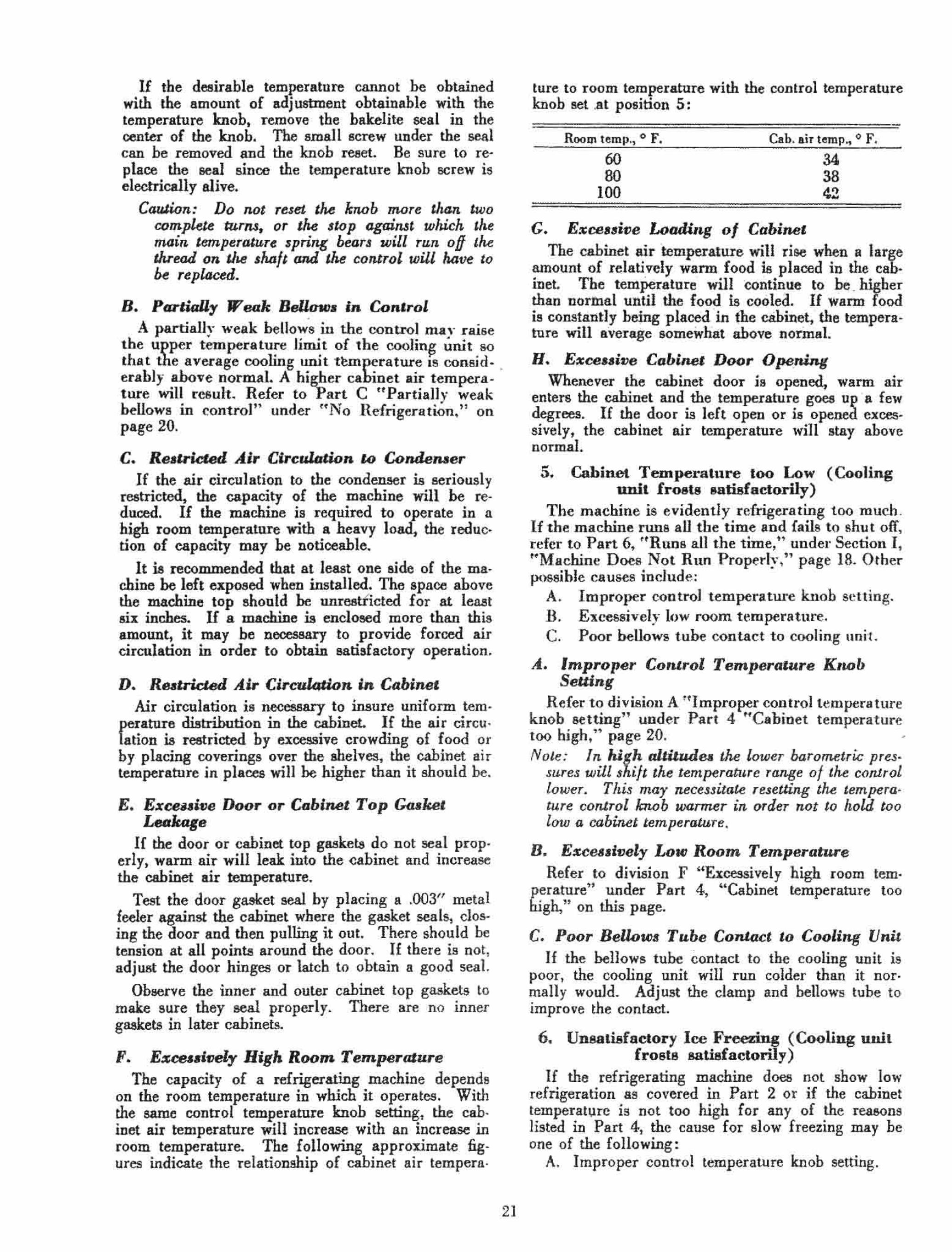
on the room temperature in which it operates. With the same control temperature knob setting, the cabinet air temperature will increase with an increase in room temperature. :rhe following approximate fig· ures indicate the relationship of cabinet air tempera.
21
ture to room temperature with the control temperature knob set .at position 5:
-Room temp., 0 F. Cab. air temp., 0 F.
60 80
100
G. E",co .. i"e Load/lOg 0/ Cabine'
34 38 1!2
The cabinet airtemperatu:re will rise when' a large amount of relatively warm. food is .placed in the cab· inet The temPerature will continue t9 he .. higher than norinal until the food is coolea. · If warm food is constantly beingplace,l"inthe' cabinet. the tempera· ture will average somewhat · above normal.
H. Exoo .. i"e Cabi ... , Door Openin{/ Whenever the cabinet door is opened, warm air
enters the cabinet and the temperature goes up · a few degrees. 1£ the door is left open or is opened excessively, the cabinet air temperature will stay ahove normal.
5. Cabinet Tempe.t·ature too Low (Cooling unit froots oatisfactorily)
The machine is evidently refrigerating too much . If the machine runs aU the time and fails to shut off, refer to Part 6, HRnna all the time," under Section It HMachinc DoCS Not Run Properl)'." page 18. Other possihle causes include:
A. Improper control temperatw·c knob setting. n. EXL'essivel;r low room temperature, C. Poor bellows tube contact to cooling unit .
A.. Improper Con'rol Temperature K,wb Selling
Refer to division A. ~~Improper control t emperature knob setting" under Part 4 "Cabinet temperature too high." page 20. -Note: In high alliludea lhe lower barometric pres·
sures will shift the temperatll,re range of the control lower. This may necessitate reseUing tM temperature control knob warmer in oraer not to hold too low a cabinet temperature.
n. E%cea.l"ely Low Room Temperature Refer to division F "Excessively high room tem
perature" under Part 4, "Cabinet temperature too high," on this page.
C. Poor Bellow. Tube ConJact 10 Cooling Uni, If the bellows tube contact to the cooling unit is
poor, the cooling unjt will run colder than it nor, mally would. Adjust the damp and bellows tube to improve the contact.
6. Unsatisfactory Ice Freezing (Cooliug ,,"it frosto satisfactorily)
If the refrigerating machine does not show low refrigeration as covered in Part 2 or if the cabinet temperat1)re is not too hlgh for any of the reasons listed in Part 4, the cause for slow freezing may be one of the following:
A. Improper connol temperature knob setting.

•
ll. Poor conta,;l of ice tray with cooling surface. a. Tray lIot frozen in properly . h. Tray bottom surface not flat. c. Cooling unit needs defrosting.
C. Location of ice tray. D. Rubber ice tray. E. Freezing desserts.
A. Improper Control T~nperature Knob Setting
• umt
For most rapid freezing, the control temperature knob setting should be turned to position 9, so that the machine will run continuously in normal room temperatures, until the freezing is completed. In this way the average cooling unit temperature will be several degrees lower than it would be if the machine operated in cycles.
Caution: Wilen the freezing is computed, the knob should be returned to the nonnal position. Otherwise, the cabinet air temperature may be reduced to a point where freezing of food will result.
B. Poor Contact o/Ice Tray with Cooling Unit Sur/ace
The transfer of heat from the water to the cooling unit surface is accomplished largely through the con· tact 'of the ice tray with the cooling unit surface. The better the contact, the faster the freezing rate.
a. Tray Not Properly Froun in. If the ice tray is not frozen to the cooling unit
surface, the fw:zing rate will he reduced. It is rec· ommended that a small amount (quarter of a cupful) of water be spread over the cooling unit surface at the tirni the ice tray is put in.
b. Tray Bottom Surface .Not FI4t. 1£ the bottom surface of the ice tray is badly
dented or warped, good contact cannot be obtained. The surface should be straightened or the tray re· placed.
c. Cooling Unit Nee,u Defrosting. If the surface of the frost on the cooling unit i.
uneVeIJ at the time the ice tray is put in, good contact csnnot be secured. The cooling unit should be defrosted.
C. Location 0/ Ice Tray The freezing rate on the bottom shelf of the cool
ing unit is twice as fast as that on the upper shelf. Therefore, for rapid freezing, the ice tray should be placed on the lower shelf.
D. Rubber Ice Tray The ruhber ice tray is supplied for its ease in re·
moving ice cubes where a few cubes are needed at a time. It is not a fast freezing tray. Generally it will require from two to three times as long to freeze cubes in the rubber tray as in an a1 uminum tray.
E. Freming De .. eru The time required to freeze desserts depends on
22
thc constituents used. It is usually somewhat longer than the time to freeze water.
•
7. High Per Cent Running Time (Cooling unit frosts aU right)
II the per cent rUDning time of a machine seems abnormally high, the possible cause may be f-ound ill one of the following sections: r. Machine does not run properly.
6. Run. all the time, page 18. II. Unsatisfactory refrigeration (Machine runs all
right) . 4. Cabinet temperature too high, page 20. 5. Cahinet temperature too low, page 21.
8. High Power Con8umption (Cooling unit froots satisfactorily)
If the power consumption of a machine seems abo normally high, refer to Part 7 "High per cent running time."
Ill. NOISE (MACHINE RUNS AND REFRIGERATES SATISFACfORU,y)
The refrigerating machine is designed for quiet operation. However, like any piece of moving mechanism, it will have certain characteristic sounds which, though hardly noticeable, can be distinguished. Occasionally, because of abnormal operating conditions, improper adjustment of the starting relay, or a defect in the mechanism; the noise may be ohjectionable.
Symptoms In order to classify the various sounds that can be
distinguished, the following list will serve as a guide:
1. Relay starting noise. 2. Unloader starting noise. 3. Compressor noise. 4. Cooling unit thump. S. Float valve discharge noise. 6. Relay hum. 7. Bumper or suction tube hitting case. 8. Radio interference.
Adjustments 1. Relay Starting Noise
This is a buzz or chattering sound coming from the starting relay only when the machine is starting. It is caused hy faulty alignment of the armature.
Caution: Do 110' auempt to adjust the ar_re by bel/ding or ,willing it. The tellJion on t.hi& part is carefully reguu.ted at the factory to insure proper starting of the machi"e.
Loosen or tighten the two screws holding the relay to the cabinet top or the condenser. Notice whether the noise is still present when the machine is started. It is possihle that the warping of the relay base, caused by tightening down the screws holding it, was suflicient to change the alignment of the armature. The small washers under the two corners of the relay base are sometimes used to reduce this warpage. Add another small washer if necessary.
If the nois~ cannot be eliminated in this way, the starting relay mllst be replaced. Refer to page 12 for instructions.
2. " Uoloader Starting Noi.., This is a vibrating hum or buzz coming from the
unloader only when the machine is starting. It is due to the fact that the un loader is in the motor magnetic field which is especially strong during the startiitg period. It cannot be eliminated.
3. Compressor Noi8e Compre!sor noises can he divided into three gen-
eral classes as follows: A. Flutter or clicley noise. B. Gurgling or frog pond noise. C. Rumble or groan noise.
.4.. Fluller or Clicky Noi.e This noise varies considerably in quality depending
on the cause and the conditions under which the rna· chine is operating. It may have a fluttering or sputtering sound as though liquid were present, or it may have a dry clicky sound, or again it may re!-emble a light metallic vibration. In an extreme case, it may appear tv he a heavy mechanical pounding. The noise may be steady throughout the cycle like the liquid pumping noise experienced in DR type refrigerating machines after defrosting, when requiring the monitor test, or when operating with a defective oil conditioner. The noise may be intermittent much like the vibrating burr found in some DR type machines.
The possible causes of the flutter or dicky noise include:
a. High cooling unit temperature. b. Liquid refrigerant in the lubricating oil. c. Pull·down after installation or after being shut
off for a time. d. Cold room" temperature. e. Changeable room temperature. £. Defective oil conditioner. g. Non-condensahle gas.
a. High Cooling Unit Temperature The load on a machine depends on the cooling
unit temperature; the high3r the cooling unit temperature, the greater the load on the compressor and motor. The noise likewise follows the cooling unit temperature. When the cooling unit temperature is above the !,ormal operating range, the machine may be somewhat noisier than normal.
b. Liquid Refrigerant in the Lubricating Oil If liquid refrigerant collects in the base, a machine
will he noisier than normal until the refrigerant is boiled out of the lubricating <iiI. The oil conditioner prevents the accnmulation of refrigerant except under abnormal conditions.
c. PuU.Jown After Install4tion or After Being Shut off for a Time
Because of the high cooling unit temperature and the liquid refrigerant in the lubricating oil, a machine mali be noisy during the pull·down period after in· sta lation or after being shut off for a time. If the cord connector is plngged into the relay so that the
23
oil conditioner is placed in the circuit for 8 few minutes before the machine is turned on, the noise during the pull.down period will he considerably reduced.
d. Cold Room Temperature If a machine operates in a cold room temperature
(below 60° F.) for a period of time, some li~uid re· frigerant may collect in the base and the machine may be slightly more noisy than normal. If the room temperature goes below 60° F. at night, it is possible that the machine may he found sligl.t1y noisier than normal in the night or in the early morning although it will operate quietly at other times. Some machines may be found to he more sensitive to cooler room temperatures than others.
Another factor that tends Lo make a machine run slightly noisier in a cool room is that the temperature knob is frequently turned to a warmer position which raises the cooling unit temperature.
e. Changeable Room Temperature U a machine is operating in 8 relatively cool room
temperature and the room temperature rises rapidly several degrees, the condenser wiIl warm more quickly than the hase 80 that some liquid refrigerant may condense in the base. As soon as the base warms uR', the refrigerant will be expelled and the machine wIll again sound normal.
/ . Defective Oil Conditioner An oil conditioner which is burned out or open
circuited will allow the accumulation of liquid refrigerant in the base, and a slightly lowered frost line.
Refer to "Checking and Replacinf the Oil Condi· tioner" on page 27, lmder uGenera Adjustments."
II. N on""ondensable Gas Non.-condensable gas in the float valve or condenser
will raise the case pressure and consequently the load on the compressor, and will cause condensing of liquid refrigerant in the base. The Hoat valve and lower con· denser turns will be relatively cooler than the upper condenser torns and will feel cooler to the hand.
Refer to HHJeeding Instructions" on page 25, under 'fGeneral Adjustments."
B. Gurgling or Frog Pond No;,e This is a periodic hubbling noise coming from the
compressor whi1e the machine is running. It re· sembles the sound coming from a distant frog pond on 8 summer night. It is caused by refrigerant bub· bling through the oil and can often be eliminated from the few machines where it will be found by changing the temperature setting of the control or hy bleeding 8S described under "General Adjustments."
C. Rumble or Groan No;,e This is a pulsating hollow tone which frequently
seems to be more objectionable outside the room than inside the room where the refrigerator is installed. Often the house construction (hollow walls, pipes. etc. J is such that the nunhle is carried to other rooms. It is usually possihle to eliminate the trouble by hleed· ing acconling to instructions under "General Adjust. ments."

4. Cooling Unit Thump
In some machines there occurs a single thump from the chilling unit directly after the machine starts. This thump may not make its appearance for several months after !he machine is installed. It is caused by a slug of refrigerant breaking through the oil film over the refrigerant in the cooling unit. It can be eliminated hy bleeding properly and Monitor Testing if necessary.
5. J!1oat Valve Diaeharge-Nol8e This is a hissing noise coming from the float valve
at times when the float opens. It arises from the liquid refrigerant discharging through the float valve orifice. It cannot be eliminated.
6. Relay Bum This is a 60 cycle hum ('.omin~ from the core of the
starting relay while the machme is running. It is caused b~' loose 1aminat.ions. Replace the relay, re ~ ff'.rrin~ to im;tl'uctions on page 12.
7. Bumper or Suction Tube Hitting Case
This is a rattle or vibrating noise, occasionally f ouod during normal running of the machine but more likely found only when the machine starts or stops. It can he verified hy shaking tbe maehine gently and observing whether the noise is reproduced.
Check the level of the machine. It is possible that the noise can he eliminated by a slight cbange in the level of the refrigerator.
8. Radio Interfere .. "" There is no radio interference during the normal
running of a machine. If radio interference should be traced to the refrigerator, there may be a ground or short circuit in the re.frigerator. Refer touGrounded circuit," page 15, and UShort circuit." page 16. under Section I "Machine Does Not Run Properly."
IV. LEAKS The refrigerating machine is of hermetically sealed
Monitor Top design, carefully eonstructed and tested to insure against leaks. Should a leak occur after the machine has left the factory, it will seldom he recognized as sueh for two reasons: (1) the leak will prohably he inward 8ince the pressnre within the machine is helow abnospheric under most conditions; and (2) methyl formate is practically odorless eVen if it should leak o~tward. A leak will u8ually appear as non·condensable gas (air) collecting in the float valve.
Non.condeosable gas will restrict the operation of the float valve as explained on page 19. under HUn_ satisfactory Refrigeration," and all of the sYn:J.ptoms resulting Irom non-condensable gas are des~jbed in detail in the uBleeding Instructions~" on page 25, under ttGeneral Adjustments."
• However the presence of non-condensable gas does
not necessarily mean the machine has an external leak, and the machine should he properly and com· pletely bled as ~xplained in the "Bleeding Instruc-
24
tious," on page 25, under trGeneral Adjustments. H
If a machine fails to refrigerate because of non-con· densable gas, is completely and properly hied, and then fails again because of non-condensahle gas within a relatively short time, it is quite possible that it is a "leaker." The machine should he properly hied again, and if failure then occurs after a short time, it is almost surely a "leaker." Should such a rna· chine he returned to the factory, it should not he bled after the last failure. hut returned with the non·condensable gas remaining in it.
Caution: 11 mus! be Temembued that if tl .. rna· chine is nol PTOpeTly and completely bled each time, a false indication of a "leakeT" may be given. This is true since incomplete bleeding mean.< that some 1IOn·conden.sable is left in lhe machine, and. the formation of a relatively 8-mall amount of non·condensable gas mar c.allle un· satisfactoTY TefrigeTation. Always follow the " Bleeding J nstru.ctWn.r."
V. F1NISB ON CA·IA AND CA·2A UNITS The following instructions ate for touch-up work
on scratches, nicks, mars, etc., only, and are primarily for the inspector's use in the home. Units will rarely if ever need complete refinishing because of Ihe inherent qualities of the Glyptal-haked enamel put on them at the factory. Complete ' refini;ming, sbould it he necessary, should he done with the Mme material. and by the .. me methods as preseribed for cahinets in the Refinishing Manual. -
For Touch-up Work Material
Use Cat. No. 58X69 special Glyptal Enamel Patcbing Kit This kit includes the following:
One bottle of Glyptal Enamel ...... CaL No. 58X70 One hottle of Glyptal Thinner ...... Cat. No. 5ax71 One hottle of Cleaning Solution .... Cat No. 58X72 One ~ ineh Fine Camels Hair Brush Cat. No. 58X73 Four small squares of Emery Paper.
Procedure Small spots, scratehes and nicks can best he re
paired hy spotting with nnthinned material and smoothing over hy a quick wiping operation with the thumb or one finger. Somewhat larger spots should he sanded to a feather edge and hrushed in as smoothiy as possihle with the glyptal enamel thinned 10 a brushing consistency. If the joh does not hlend into the surronnding 8urface very well it may he improved "J quickly Rowing clear thinner over the patched an surrounding area with long faSt strokes.
VI. GENERAL ADJUSTMENTS A certain number of general adjustments apply to
various CA unit trouhles, and these are listed and discussed helow:
1. Bleeding Instructions .
II. Monitor Test Instructions for adding Methyl Formate.
III. Checking and Replacing the Oil Conditioner.

1. Bleeding Imtruwons The methyl formate refrigerant used has the unique
property of taking care of any excess moisture in the system, by forming harmless non-condensable gas. Absolutely no corrosion or sticking of mechanica I parts 01' freezing of the Hoat valve will result from moisture in the CA machine.
Also, since We boiling point of ~ethyl formate is 88° F' j ~he interna,l preseures will t,lsually be below atmospheric, and any small leaks ~il1 allow air to be drawn into the system, whiCh collects in , the float chamber as non-condensable gas.
Given below are complete symptoms by which ilon· condensable gas in a CA machine may be recogni7.ed. and detailed instructions for bleeding it from the machines. .
Note: Bleeding is the term we we now wing in.stead of pur~, to diDerenJiate between the present method of bleeding 08 nOll-condensable gas and the u.sual pu.rging oj refrigerant.
Symptom. 1. Difference in temperature (15° to 20° F.) be·
tween the side of the Hoat valve and the upper can· denser coils.
This temperature difference is easily detected by the hands, and is caused by the non-condensable gas collecting in the top of the float chamber. The presence of the non-condensable gas restricts the flow of warm refrjgerant into the float chamber and insulates- the walls and top of the float valve from the refrigerant, causing a decided temperature difference.
Note: 1/ the m4Chine is in a cool rooln ,emperature (below 70' F.) it will be necW4rr to laeal u.. machine by running il with a Monitor Telt heater or trars of warm water in 'he coo.~ing unit in order to show the temperature difference.
1/ the system has an. excess amounl 0/ non-con· denJable go.s, tlte condenJer may remain the same (JJ: tM float tem.permure and the dome Jhould be used lor comparuon.
2. Erratic Refrigeration. The cooling unit may periodica1ly defrost alA
though the machine continues to operate. This will be particularly noticeable in cooler room temperatures since the non-condensable gas has more effect on the operation of the float valve when the machine is operating under lower tern· peratures and pressures.
When the room temperature is low the unit win run cool and the pressure of the refrigerant will be low within the machine. This low pressure refrigerant will have a harder time forcing a way into the float chamber against the pressure of the non-condensable which remains the same. Near normal operation may he obtained in a high room temperature, with erratic refrigeration reo sulting from a low room temperature.
3. Low Frost Line, The frost line rna y be below the right, or both
headers since the non·condensable gas causes con· densation of liquid refrigerant in the base; thus, taking some from the cooling unit.
25
Note: Low jrol t can 01.«0 be cau. .. ed by 0 defective oil contiilwMr (page 27). a leaky check valve (page 20), or a low refrigerant charge (page 19).
4. No Refrigeration. Non>condensable gas restricts the operation
of the float 80 that no refrjgeran~ is returned to the cooling unit. This is afiected by room tem· perature .as explained under "Err.lltic Refriger:a. tion."
If the machine fails to refrigerate because of non-condenaable 'gas it should he' noted that there will b;e little. temperature di-ffere~ce . between the float :valve-and the condenser- due to the fact that no work .is ·bejDg done by the machine ·and the condenser will not he·at up.
5. Noise. There will be a "tinny" noise during the run·
ning period caused by liquid refrigerant in the base mixing with the oil. This will he more noticeable in cooler room temperatures.
Note: A defeclive oil conditiOner wiU cause this noi .. and should alwaY' be checked (page 27) .
6. Trip. Of! or Stan •. A large amount of non·condensable' gas may
increase the internal pressure enough to cause tripping of the overload or stalling of the com· pre..llSOr.
Note: A defective .starting relay may al.so couse periodic tripping 01J.
E ... n.ial. for Bleeding 1. Heat the Machine.
This raises the internal pressure ahove atmos· pheric, so no air will be drawn into the system, and assures all of the non~condensable gas being forced into the float chamber. A Monitor Test heater or pans of warm water may be placed in the cooling u,}it or the condenser can be blan· keted to heat the machine.
Caution: Do not let the healer coil touch the 314inle.sJ 3teel.
Do not let the cooling unit, dome or condenser temperature get hotter than what the hand ~ah stand.
2. Keep the Machine Running All the Time. This must be done to maintain a positive pres
sure and to keep the non·condensable gas in the float valve.
Note: 1 j the TlUlChine stalls or trips out dlLe to noncondelUable, it should be bled slowlr until it can be kept running, The pressure will be out· ward if non-conderuable is the cause.
3. Check for Outward Pressure. Remove the float valve cap and the auxiliary
seaHng screw. Note: Some of the sealing screws were soldered
and can be broken loose .with a 14rge screw driver , Qr the solder call be softened wuh a Monitor Test lu!ater.
Put light oil in the purging screw socket, and open the purging screw just a crack to make

sure the pressure is outward. If oil - is sucked in, close the screw immediately.
4. Bleed for Three Minutes Proper Rate.
This must he done at the proper rate so that the least amount of refrigerant is lost. Bubble the non-condensable gas through the oil as fast as possible without blowing all the oil out, and with· out getting an odor of methyl formate with the nose sh inches above the purging screw.
5. Close Purging Screw for One Minute. This allows the non·condensable gas in the
float valve to collect .t the top so that the next time the purging screw is opened, nearly pure non-condensable gas is hIed.
6. CODtinue Bleeding Until All the Non·con· denoahle Gas is Removed.
When the float valve temperature warms up equal to that of the upper condenser coBs, all of the non-condensable has been removed. Continue the three-minute open and one-minute closed periods until these temperatures are equal. The bleeding rate should be decreased towards the end of the operation as the amount of non-condens.ble decre .....
CalLlion: TM. S<JtislactDry operation of the 11l4Chine depend. on its being correctly and completely bled.
If tM. purging screw is opened wide and the bleeding rate increased, tM. sudden release 01 pre55ure in the float valve wiU canse a tJiolenl boiling and mixing 0/ the non-conderuable gas and the refrigerant.
TM. float will IM.n warm up prematurely, indicating the end of the bleeding operation be· fore all of the non-condensable ga.s ha4 been removed. Proper bleeding cannot then be continued until the non-condernable gas and refrigerant Mve separated.
Fast purging also causes the loss oj an excess of refrigerant which will soon aDect tM. refrigerat. ing capacity of the machine.
2. Monitor Te.t Inatmctions
Methyl form.te refrigerant sbould be added to • machine which proves definitely to have a low refrigerant charge.
Monitor Testing is the term used to designate .dd· ing refrigerant to a refrigerating machine, and is .ccomplished by connecting • small drum or bottle of gas to the purging screw by means of an adapter. The set.up is shown in the accompanying drawing:
Equipment needed is as follows: Monitor Test Kit (C.t. No. llX764). Monitor Test bottle, containing lh pound of
methyl format., which is p.inted white (Cat. No. 58X311).
Special circul.r ad.pter wrench for CA Form A m.chines (Cat. No. A18H12).
The procedure -and equipment used is essentially Ihe same as was used with the old- DR machines, w-ith the following speci.l conditions:
, 26
1. Never add gas until all non-condensable gas bas been bled from the machine. Refer to HSvmp. toms" and rtBlcedjng Instructions." on ~ pauc 25, under ttGeneraJ Adjustments. ~' 0
2. Use only methyl formate.
3. Never open the purging screw in tbe float valve, bottle, or adapter to the .tmosphere until the machine or bottle has been he.ted. This as· sures that no air will be drawn into the system, and gives an opportunity to check for noncondensable g.s.
4. Use only R clean adapter.
5. On the CA Form A it will be necessary to u .. the C.t. No. A18H12 circul.r wrench to tighten the ad.pter nut to tbe purging outlet. The use of the wrench is illustrated in the drawing of the Monitor Test set-up.
6, Keep open /lames aw.y fram methyl formate, as it is inflammable.
A
,
,
Procedure 1. Heat the machine and fill the purging screw
socket with light oil. Crack the purging screw and test for outward pressure.
2. Inspect the Cat. No. llX765 Monitor Test .dap. ter to see th.t it has a single good · Cal. No. llX768 lead washer in pl.ce on e.ch side, and that the purging screw in its side i. closed. Be sure the .d.pter is clean. Loosen . the bottle purging screw with the C.t. No. llXl22 purging wrench and .... mble the bottle to the adapter. Insert the valve stem into the bottle purging screw and tighten the valve stem nut.
3. Pl.ce the bottle and adapter just .... mbled over the 80at connection, and tighten the adap·

ter' mit. (On CA Form A machines use the cirv
eular wrench.) Entcr the valve stem into the float valve purging screw and tighten the valve stem gland nut.
4. Assemble the Cat. No. llX766 heater over the bottle and plug it into an electric outlet. When the top of the bottle is very warnl, open the bottle purging screw slightly, allowing methyl formate to enter the adapter, and then close the bottle purging scre,w. Open the purging screw in the adapter and purge out the air. If the bot~e is warm enough and the air is 'out, the odor of methyl formate should be noticeable.
5. Open the Hoat valve purging screw and the bot· tle purging screw three complete turns an~ pull out the valve stems. Leave the purging screws open until the bottle is empty which is indicated by the fact that the "alve end of the bottle gets ve.q warm.
6. Close the Hoat purging screw and the bottle purging screw and open the adapter purging screw to relieve the pressure in the adapter. If liquid is in the adapter, the bottle has not been heated long enough. If a large amount of gas escapes, close the aaapter purging screw, and op~n the float purging screw and the bottle purging screw and reseat them.
7. Remove the adapter and hottle, and check the float valve and bottle for leaks with light oil. Replace the auxiliary sealing screw and the cap over the float valve purging screw socket.
3. Checking and Replacing the Oil Conditioller
The oil conditioner is a small 12 to 15~watt heating element located in a sealed tube projecting into the oil sump in the base of the compressor. It is connected directly across the line at the starting relay, and therefore is always drawing current whenever the unit is plugged into au electrical service outlet.
It is installed through a small hole in the curved portion of the cabinet top skirt, just below the com· pressor case lins. This hole is at the back of the machine and is filled with a rubber plug.
The function of the oil conditioner is to prevent excessive condensation of refrigerant in the oil, and also to keep the oil warm and thin, which brings about a reduction in the watts drawn by the compressor.
CheclUng the Oil Conaitioner There are three ways to check the oil conditioner: 1. Series test i4ntp. If an ordinary 25·watt lamp
is connected with suitable plugs so that it can he put in series between the electric service outlet and the machine connecting cord plug, it ofIer~ the easiest and most satisfactory method of checking the oil conditioner. With the {:ontrol main switch turned "off," the lamp should glow with ahout half brilliancy, showing ;1 circuit through the oil c!onditioner. If the oil conditioner is open circuited. the lamp will nol light at all and, if short circuited, will light with nor· ma.l brilliancy,
27
Replacing on Conditioner
2. Spark an oil conditioner lead. One of the oil conditioner leads in the starting relay can be disconnected and, after replacing the connecting cord plug in the electric service outlet, it can he sparked to its terminaL The oil condi· tioner leads are in green-covered cables and have terminals on the ends. They are attached to the two terminals which form part of the locking prongs projecLing from the relay. 1t may be necessary to darken the vicinity of the lead being sparkeQ in order to see the spark. No spark would indicate an open-circuited oil conditioner and an unusually large spark, a short circuit.
3. Remove oil conditioner. The oil conditioner can be removed as described below. If the heater element i8 hotter than the hand can stand it is all right.
Replacing the Oil Cont/itioner I. Remove the rubber plug which fills the hole ill
the cabinet top at the fear of the machine.
Caution: Do not pu-sh it inward.
2. With a pair of duck·bill pliers or a hooked wire, fish around inside the cabinet top until you can pull out a section of the green cable. Continue pulling the cable until the oil conditioner comes out.
Cau.J.wn: Do not attempt to hold the porcelain part (unless the oil conditioner is "dead") nor let it rest on the unit fini.~h_
3. If the oil conditioner is holte·r than the hand can stand, it is all right. Otherwise, replace it by cutting off the leads at the taped joint, soldering on a new Cat. No. II X 100 oil conditioner, and retaping the joint.
4. Place the oil conditioner back in its tube, using a flashlight to make sure it really goes into the tube the fun distance and not down into the cabinet top insulation.
:i, Replace the rubber plug in the oil I.:o nditioner hole. This is important to prevent the condensation of moisture in the cabinet top_

Ucatiug Evaporator Bleeding Non-condeosable Gas
•
DieOOnneeting Control Mooitor Test Equipment
"'
Adding Refrigera'ot to Form A Machine Adding Refrigeunt to Form B Machirie
28

Uncrating, Inspection and Installation ,
Machine
•
Remove the cover of the shipping crate. Lift the machine from the crate.
Note: If collapsible lifter Cat. llX384 is used, special long lifting hooks Cat. 58X32 must be sub· sti.tuted for the hooks originally supplied with the lifter. .
Removin« CA Fonn A Unb fro.m Crate
The wooden rack comes oui- of the crate along with the machine, to protect the finish on the edges of the cabinet top as it is being removed. The rack is fastened to the bottom plate by two clips nnder two of the screw heads holding the bottom plate to the box top. See the above illustration.
To remove the rack, loosen the screws and turn the clips back under the rack. Be sure to tighten the
• screws agam.
Note: Whenever one of these machines is shipped, the wooden rack must be properly assembled to it before placing it in the shipping crate.
/nspeetion
At the time the machine is uncrated, examine it carefully for possible damage during shipment. If
29
damage is found, examine the crate and, 8 S nearly as possible, ascertain the reason for the damage.
Also, inspect the machine as follows: 1. Make sure the finish is all right. 2. Make sure that the rubber plug properly seal.
the oil conditioner hole.
Cabinet Ullcrallng
A reasonnble amount of care should he used in remo~ing c~inet from the crate. An examination of the crate will generally indicate the best method to use. Most of OUf crates are easily removable by pulling the nails in the rear of the crate, The cab· inet will then slide out, after which the packing collars arc removed.
lnspeeaan Examine the cabinet for the following points: A, Fit and operation of the shelves, B. Chips or mars on interior or exterior finish. C. Operation of foot.pedal door opener. D, Operation of light. E. Condition of seal around box top opening. F. The two wood strips which protect the sponge
rubber gasket from the shelves on some models during shipment are removed. (The use of the sponge rubber gasket was discontinued on the X·7 and T·7 models, Reference to it be· low applies to the HT and HX models,)
Installation
When the machine is being instal led in a cabinet, -care must be taken not to damage the liquid tube from the float valve to the cooling unit OT any of the other pipes.
Before lowering the machine into the cabinet, examine the No-Ox-Id cloth around the box top opening of the cabinet. If it is loose at any point, iron the No-Ox-Id cloth down with a piece of wood.
After the machine is lowered into the cabinet, cheek the seal of bol" cabinet top gaskets, The seal of the outer (or upper) gasket is most important and must be made tight. If necessary, trim the gasket on the liner. The outer seal is required to prevent condensation of moisture between the cabinet walls.
The cabinet should be installed reasonably level and should set firmly on all four legs on the rubber gliders. It should not be set against the wall or against anything else,
In order to insure sufficient air circulation to the condenser, at least onc side of the machine must he left exposed for the whole width of the cabinet. At least six inches of unrestricted space should be left above the machine top.
The control temperature knoh should be set at position 5 for nonnal service.
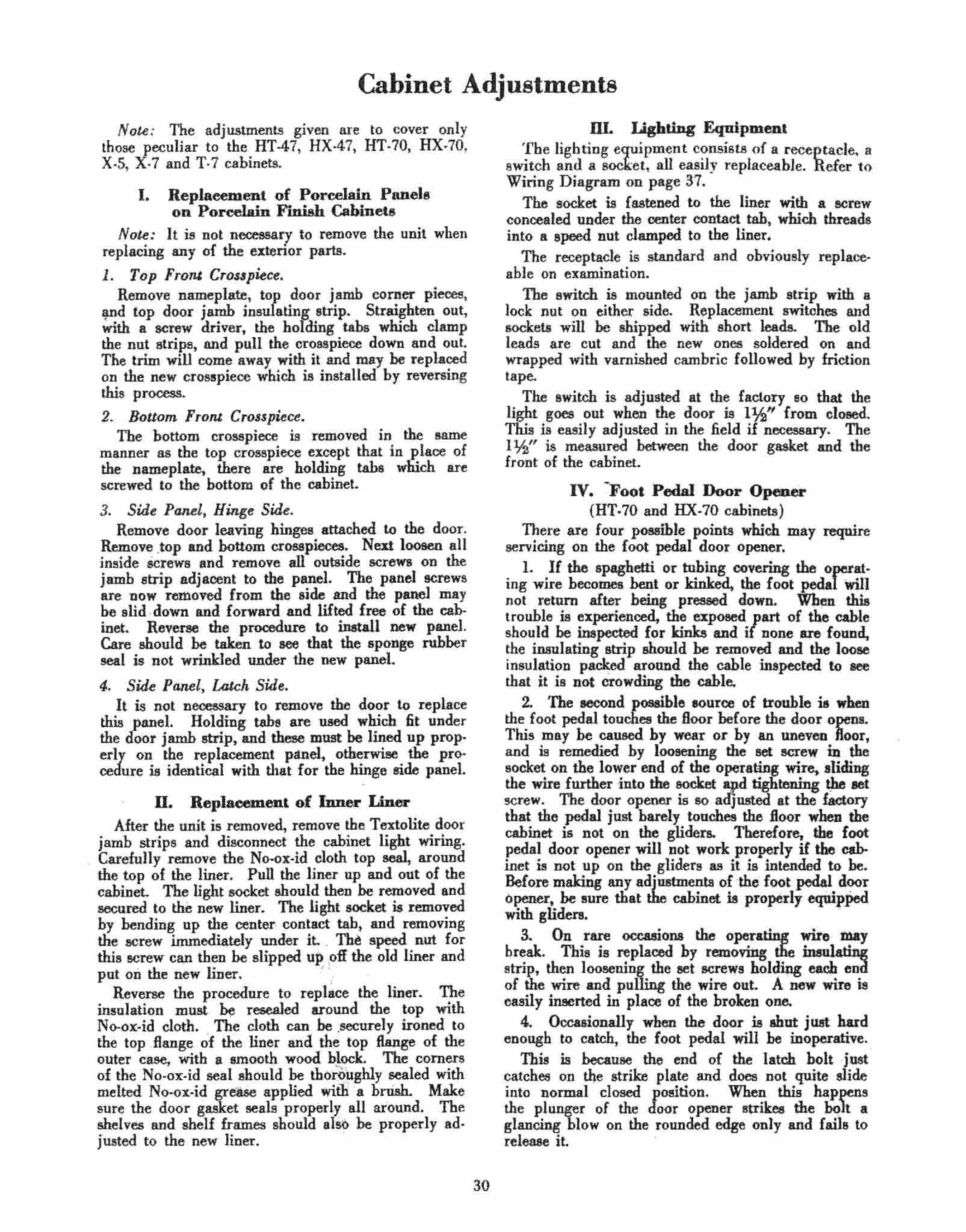
-
Cabinet Adjustments
Note: The adjustments given are to cover only those peculiar to the HT·47, HX·47, HT·70, HX·70, X·5, X· 7 and T· 7 cabinets.
I. Replacement of Porcelain Panel. on porce1ain Finish Cabinets
Note: I t is not necessary to remove the unit when replacing any of the exterior parts.
1. Top Fronl CroS$pkc •. Remove nameplate, tor, door jamb corner pieces,
and top door jamb insu ating strip. Straighten out, ~th a screw driver, the holding tabs which clamp the nut strips, and pull the crosspiece down and out. The trim will come away with it and may be replaced on the new crosspiece which is installed by reversing this process.
2. Bottom From Crosspiece. The bottom crosspiece is removed in the same
manner as the top crosspiece except that in place of the nameplate, there are holding tabs which are screwed to the bottom of tbe cabinet.
3. Sid. Panel, Hing. Sid • . Remove door leaving hinges attached 10 the door.
Remove .top and bottom crosspieces. Nen loosen all inside Screws and remove all outside screws on the jamb strip adjacent to the panel. The panel screws are now rellioved from the side and the panel may be slid down and forward and lifted free of the cab· inet. Reverae the prooedure 10 install new panel. Care should be taken to see that the sponge rubber seal i. not wrinkled under the new panel.
4. Side Panel, Latch Side. It is not n~ary to remove the door to replace
this panel. Holding tabs are used which 6t under the door jamb strip, and these must be lined up prop· erly on the replacement panel, otherwise the procedure is identical with that {or the hinge side panel.
D. Replaeement of Jnner I.iner After the unit is removed, remove the Textolite door
jamb strips and disconnect the cabinet light wiring. Carefully remove the No·ox·id cloth top seal, around the top of the liner. Pull the liner up and out of the cabinet. The Iigbt socket should then be removed and secured to the new liner. The light socket is removed hy bending up the center contact tab, and removing the screw immediately under it. .. Th~ speed nut for thi. screw can th~n be slipped u~ pH the old liner and put on the new lIner. "- ,. .
Reverse the .procedure to replace the liner. The insulation must "" resealed around the top with No-ox·id cloth . . The cloth can be .securely ironed to the top .flange ' of the liner and the top flange of the outer ease, with a smooth wood' block. The corners of the No·ox·id seal should be th6~ughly sealed . with melted No·ox·id gress.. applied with 'a brUsh. Make sure the door gasket seals properly. all around. The shelves and sbelf frames should also be properly ad· justed to the new liner.
30
DL I.ighting Equipment The lighting equipment consists of a receptacle~ a
switch and a socket, all easily }·eplaceable. Refer to Wiring Diagram on page 37.
The socket is fastened to the liner with a screw conoealed under the center contact tab, which threads into a speed nut clamped to the liner.
The receptacle is standard and obviously replaceable on examination.
The switch is mounted on the j 8mb strip with a lock nut on either side. Replacement switches and sockets will be shipped with sbort leads. The old leads are cut and the new ones soldered on and wrapped with varnished cambric followed by friction tape.
The switch is adjusted at the factory so that the light goes out when the door is l¥.(' from closed. This is easily adjusted in the field if necessary. The I %" is measured between the door gasket and the front of the cabinet.
IV. "Foot Pedal Door Op".oer (HT.70 and HX·70 cabinets)
There are four possible points which may reqilire servicing on the foot pedal door opener.
L If the or tubing covering the operat. ing wire becomes bent or kinked, the foot pedal win not return after being pressed down. When this trouble is experienced, the exposed ,art of the cable should be inapected for kinks and i none are found, the insulating strip ahould be removed and the loose insulation paclfed around the cable inapected 10 see that it is not crowding the cable.
2. The second possible lOuroe of trouble i. when the. foot pedal touches the floor before the door opens. This may be caused by wear or by an uneven floor, and is remedied by loosening the set screw in the socket on the lower end of the operating wire, .Iiding the wire further into the socket apd tightening !)Ie set screw. The door opener is so adjusted at the factory that the J>C!lal just barely touches the Boor when the cabinet is not on the gliders. Therefore, .thofoot pedal door opener will not work properly if the c.binet is not up on the gliders as it is intended 10 be. Before making any adjustments of ·the foot pedal door opener, be sure that the cabinet is properly eqwpped with gliden. .
3. On rare occasions the operating ..rue. t!"y break. This is replaced by removing the inau •.
of the WIre and pul the WIre out. A new WIre 18 easily inserted in plaoe of the broken one.
4. Occasionally when the door is shot juat hard enough to catch, the foot pedal will be inoperative.
This is because the end of the latch holt j.nst catches on t1Je strike plate and does not quite slide into normal closed position. When this happens the plunger of the door opener strikes the bolt a glancing hlow .on the rounded edge only and fails to rele.ase it. .

I
I
H23A3-~
H23A2--
H23A5--_
H23A8---, -
23A I
+----H23A4
+----H23A7
..----H23A8
---H23A9
'---, -H23AIO
r---H23A7
;::::::::; --H23AI2
'---H23A3
FOOl Pedal Door Opener Replacement Part~. HX_70 and HT_70 Cablnel.
The existence of this condition is easily determined by chalking the end of the plunger and observing where it contacts the bolt
This condition is easily remedied and positive operation in all bolt positions secored by changing the relative angle of the plunger, by bending the bracket, as shown on the following illUBtration.
To do this, remove the Textolite strip and the kapok insulation packed loosely around the mechanism. Now remove the two flat headed machine screws which hold the mechanism to the case and take it out where it can be bent as illustrated.
X-5, X-7 and T-7 Cabinets The foot pedal mechanism is not interchangeable
with the 1933 type. The foot pedal is connected to the door opener with three rods, which are hooked to· getber. The middle rod passes through a stuffing box attached to the cabinet bottom. This stuffing box is packed with wool packing and grease which does Dot allow air leakage and allows free movement of the
31
rod. The lower rod hooks into the eye on the end of the middle rod which allows an easy disassembly. The lower end of the bottom rod is threaded and screws into 8 connector which has a hall end. The
SUPPORT ...... KIN'" 4NGlE l..AR.ER
"INSTALLED POSITION 0'
POSITION Of
ball in turn fits into a socket in the foot-pedal. For adjusting:
1. Open tbe cabinet door. 2. Pull down on the bottom rod and disengage the
ball and socket joint. 3. Loosen Jock nut on top of connector piece and
screw the connector in ! or out to shorten or lengthen the lower rod o'
4.. Tighten lock nut an& reassemble. The door opener mechanism is permanently at~
tached to the escutcheon plate which in turn is fastened to the Textolite strip with two screws. The holes for these ~crews in the escutcheon plate are slightly oblong, as are the boles in the strike plate allowing for movement of the complete mechanism. Then, when adjusting for door seal, the tongue of the door opener can be kept in the same position relative to the iaten bolt.
Parts of "e foal pedal itself and the bottom tread are obviously replaceable. The stuffing box and the door opener itself are also replaceable by removing the Textolite strip which covers them and the screws whicht hold them in place.
V_ Door Seal Poor door seal usually results in complaints of cab·
inet sweating inside, exc~sive frosting of cooling unit, high per cent running time, high power consumption, slow ice freezing and high cabinet air tempera· ture.
Imperfect door seals may be located by the use of a 0.003" metal feeler. Locate the point of poor seal by inserting the feeler at various points around the door between the gasket and the cabinet front.
If a poor seal is located, first check the gasket to see that it is not excessively worn. Check the hard-

ware to see that it is not sprung or worn and that the screws are tight.
The strike sbould be inspected and adjusted ., follows:
The strike plate is in two pieces of which the strike bar is adjustable. By loosening the two screW6 in the plate tbis bar can be moved in or out. When the strike is properly adjusted there -ohould he ~" free movement at the end of the latch handle when the door i. closed. If the strike bsr is too rar out there will be no free movement. If it is too far in, the free movement will exceed lh".
Often a poor door seal call .be corrected by rehangin/! the door; by replacin!!-thegasket; or by properly adJustmg or replacmg the 'hardware.
If, however, the poor door se8l is caused by tbe door being sprung out of line, or by the front of tbe cabinet being out of line, it can be corrected as follows:
(The operator should he provided with a straight. edge approximately 2" longer than the long side of the door, a rubber mallet, a metal feeler approximately *" thick and a screw driver.)
J. With the straightedge check the cabinet front on aU four sides, approximately where the door gasket seats, to see if tbe front is straight. If it is possible to insert the h" feeler between the straightedge and the face of the cabinet such points should be corrected.
If an urievenness does exist, it is very likely that the cabinet front will be bulged outwsrd, generally at the "-enter of the Textolite strip.
2. When tbe front is bulged outward, loosen the Textolite strip screws approximately 1'12 turns on all four side. of the door opening- front side only, not on the; liner side.
3. Pound the high point of the cabinet front and keep checking with the straightedge until a com· paratively even, flat surface is obtained. If done properly tills will not in any way injure the finioh. When the front i. straight, tighten up all the screws.
4. If the cabinet front is found to be bulged in· ward, it will probably be fonnd necessary to remove the Textolite strip at that point and pull the front of the cabinet out so that it makes a bulge forward. Then proceed a. above.
VI. Shelf Fram .. on B'I'.70. HX.70. X·7 and T· 7 Cabinets
The shelf frames in the.e mod.l. may be used either side up, giving considerable variation in thelf
• spacmg. Eacb set of sliding .helves is individually fitted to
the cabinet with which it is shipped from the factory.
32
However, replacement of liners, replacement of shelves, and the mixing up of shelves may make readjustment necessary in some cases. We wish to caulion that ill adjusting the open type sliding sbelf frames which we are now using, great care must be exercised not to bend them at the welds, 01' to install ~h~ hy springing ~em in position, leaving the welded Jomts under a stram.
These shelves mu.t be adjusted by bending the tang. back and forth as required. This bending must be done in a suitable clamping device to prevent applying a strain to the _ welded joints. The ohelves should b. adjusted 50 they fit in the liner .nugly, but not so tight that they have to be forced into place. Shelves t!¥it are fitted too tight may cause chippmg of the porcelain liner.
VB. Door Gaskels
It will be noted that the door gasket is one piece and is not interchangeable with any others in the line. To replace a gasket, pull the old gasket off and pul the new gasket on the cabinet by forcing the lugs of the gasket into holes in exterior door pan witb a blunt tool or pencil.
•
"ro. InBtalJation of Six·Inch Legs On the cabinets using CA Form A units (lIT and
H.X models) standard six·inch legs may be used with the exception of the front leg with the bracket for the foot pedal door opener. The wire for the foot pedal door opener will have to be shortened to the proper length.
On the cabinets using CA Form B units (X and T models) a .hort bottom link is available and will be .hipped with the special six·incb leg.
IX. Nameplate The nameplates on the HX and HT models were
held in place with two screws. The later models (X and T line) had a different
type made up _ of two parts. A concealed cadmium plated base strip is attached to the outer case with two screws, and the nameplate proper snaps onto the base
• strip. To remove this nameplate use a small screw driver
with a bit approximately -h" wide. With the door of the cabinet open, insert the point of the bit in the slot of the nameplate shell. The slot is loe.ied in the right.hand end on the lower side.
Twist the screw driver to unsnap the nameplate shell from its base plate, being careful not to mar the Glyptsl or porcelain finish .
To re"'.emble, slide the left·hand end of the nAm.· plate shell OVer the base plate and then snap it on.
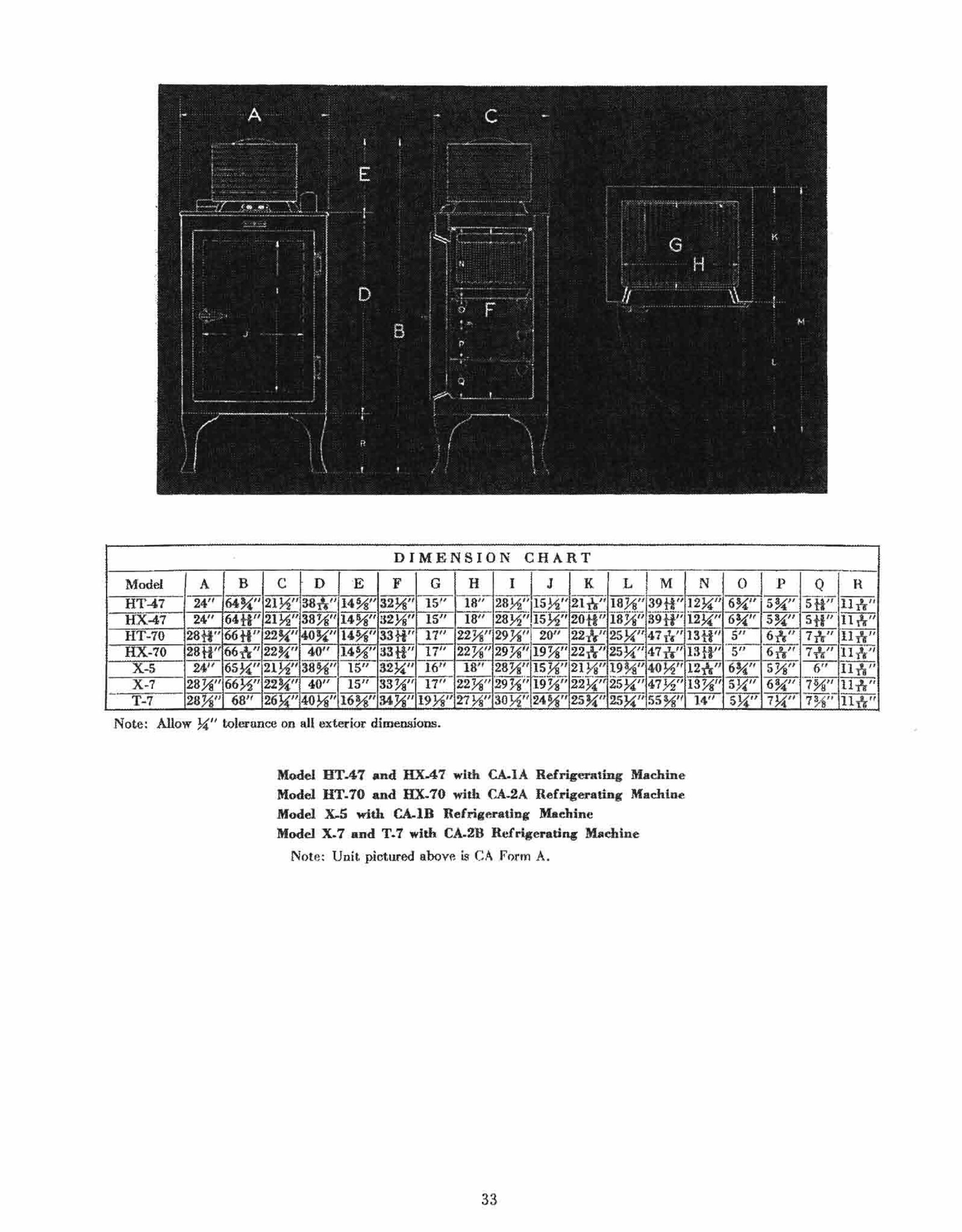
DIMENSION CHART ~~~~--,--,---.--.--,-.---
A B C D E F I J K L M
Note: Allow >i" tolcrunce on all exterior dimensions.
Model UTA7 and HX..47 with CA..IA Refrigerating Machine
Model HT.70 and HX.70 with CA-2A Refrigerating Machine Model x.s with CA..IB Refrigerating Maehinc Model X.7 and T.7 will> CA.2B Hcfrig.ratl,.. Machine
Note: Unit pictured sbove L"I CA Form A.
33
N o p R
-

Use and Care of the Refrigerator
The General Electric refrigeralor is designed to satisfy all norma] refrigeration requirements with a minimum amount of attention on the part of the user. A few instructions on the use and care of the refrigerator will assist the user in obtaining the most satisfactory service from it.
Cleaning the Interior Directly after installation and previous to the time
the machine is started, it is recommended tha,t the user carefully clean the interior of the cabinet, the cooling unit, ice trays, chiller tray, llnd food containers.
For cleaning the interior of the cabinet and the cooling unit, ~ solution of baking soda in warm water should he used. A satisfactory aolulion can he made up of one tablespoonful of baking soda in four quarts of water.
Caution: Never clean the inkrior of the cabinel or lhe cooling unit with any cleaning agent which has an odor.
CauIion: When washing the chiller tray, do not use hot water. Hot waler may cause breakage.
It is suggested that the interior of the cabinet and the cooling unit be cleaned each time the cooling unit is defrosted.
Cleani.." the Esterior
Mild aoap and warm water, or General Electric Liquid Wax should be used in cleaning the Monitor Top and the exterior of the Glyptal cabinets.
CautioTl: The use of any 01 the standard cleaning compounds which depend upon abrasif1<l or alka· lin. action will remooe the gloss from the jillish on the Monitor Top or Glyptal cabineu.
Starling the Refrigerator To start the refrigerator after it is installed, turn
the left knob on the control on the front of the rna· chine to the "on" position. The machine should start immediately.
If the machine does not start, make sure that the electrical cord is properly attached. Also, 'make sure that the house fuse on the circuit into which the reo frigerator is plugged is all righL
During the first few hours after heing started, the machine may he slightly noisy but as soon as it is ~ithin the normal. operating condition, it , will con· llnue to operate qUIetly.
Cabinet Temperalure When the refrigerator is installed, the temperature
knob at the rildlt side of the control should he set at position 5. 'the control is set at the factory to au· tomatically maintajn a cabinet air temperature of between 38° F. and 42° F. in room temperatures he· tween 70° F. and SOO F.
If the room temperature averages below 70° F., the cabinet air temperature may he slightly helow 38° F. If this is too cold, the temperature knob can be turned counterclockwise to position 4 or 3, or even to 2 or 1.
34
If the room temperature averages above 80° f., the cabinet air temperature may he slightly above 42.° F. If this seems too warm, the temperature knob can be turned clockwise to positions 6, 7, 8 t or,"9.
The temperature setting is made adjustable in order to satisfy the individual desires of the user. If it is desired to make the cabinet air ' temperature colder, the temperature knob can he turned clockwise; if warmer, the knob can be turned counterclockwise.
The use of a thermometer in the cabinet is not recommended unless it be of high quali'l' The user will find that the refrigerator is maintaining proper temperatures if the food is prese:ved satisfactorily and is cold enough for the individual taste.
m"ribution &/ F DOd in ,he Cabinet The coldest zone in the refriget~tor is within the
cooling unit where the temperature is helow freezing. The next warmer zone is in the chiller tray where the temperature may be just below or just above freezing. The warmest zone is in the cabinet where the temperatyre should range between 38° F. and 4,50 F.
Air circulation is necessary to insure unifonn tem· perature distribution within the cabinet. Therefore, do not restrict the circulation by excessive crow_ding of food into the cabinet or by placing coverings over the shelves.
The circulation of cold air in the cabinet is from the cooling unit, around the chiller tray, down the right side of the cabinet and up the left side. It is evident that foods with odors, which are not covered, should be placed on the left side of the cabinet Dcar the top in order not to affect other foods.
For most satisfactory results, it is recommended that the following foods he kept in covered con·
• tamers: 1. Those with strong or objectionahle odors such
as cantaloupes and onions. 2. Those which absorb odors readily such as
butter. 3. Liquids such as milk or cream, 4. Moist foods such as mashed potatoes or creamed
vegetables. 5. Fresh vegetables such as lettuce and celery,
(Should he kept ,in the vegetable pan.)
Free";.." lee Cub ... To secure the most rapid freezing of ice cubes, be
sure that the ice trays make good contact with the cooling unit freezing surfaces. A quarter cup of warm water spread evenly over the freezing surface will serve to level any unevenness in the frost covering the surface.
The ice freezing rate can he further improved by turning the temperature knob at the right of the con· trol to position 9, the coldest setting. When the ice is frozen, the temperature mob must be returned to the Dormal position. Otherwise, the cabinet air temperature may he reduced to a point where freezing of food will result.

To remove an aluminum ice tray when frozen, use the tray lifter, or loosen with an upward push directed against the upper rim of the tray. Do not use an ice pick or other sharp instrument. The rubber ice tray can be loosened by lifting on the handle.
To remove ice cubes from an aluminum tray with a minimum loss of ice, allow cold water from the faucet to run on the hottom of the tray until the cubes fall out. An alternate method is to immerse the ice tray in a pan of cold water. Ice cuhea are removed from the rubber tray by Hexing the tray.
DeJroding Frost will collect on the cooling unit at a rate
depending CUl. the humidity of the air entering the cabinet at times when the door is opened and on the amount of uncovered liquid or moist foods in the cabinet. It:is recommended that the cooling unit be defrosted at a time when this accumulation is approximately one-half inch thick or when the accumulation in~erferes with ¥ the removal of ice trays. It is suggested tlfat defrosting take place at least once a month ' at which time the interior of the cabinet and the cooling unit should be cleaned. However, in many cases defrosting will be necessary oftener than once a month, depending on the conditions.
To defrost the refrigerator, the switch on the left side of the control should be turned counterclockwise to the· position marked "defrost." The machine will automatically proceed to operate on a defrosting cycle, allowing the frost on the cooling unit to melt off into the chiller tray, yet not allowing the cabinet air temperature to rise more than a few degrees. On the Fonn A machines, when defrosting is completed, the main switch should be returned to the "on" posi. tion. However, in the Form B machines, the control is so arranged that the unit is automatically returned to oQrmal operation after a single defrosting cycle. Therefore it is not necessary to manually retllIo the knob from "defrost" to the Hon" position.
The ice trays, and food stored in the chiller tray should be removed previous to defrosting. The water
35
in the chiller tray after the defrosting is completed should be immediately emptied.
HoI IF' ater DeJro.ting In order to hasten the defrosting period, particu
larly in warm weather when it is desired to preserve the ice cubes and allow only a small rise in cabinet air temperature, pans of hot water can be placed in the cooling unit after either of the two following conditions are observed:
1. Turn the main switch to "off" instead of "de· frost/' Of,
2. Turn the main switch to udefrost" when the machil,e is no, ru.nning.
If the hot water is placed in the cooling nnit when the machine is running and the main switch is turned to "defrost," the machine will continue to run until the water is frozen before starting to operate on a defrosting cycle.
Re.e/ting ,he Motor Protectiv" De"ice A device is incort~~ated in the control to protect the
motor in the · mac . e in case of unusual load or power conditions. ·On the CA Form A machines, when this device operates, the motor is shut off and a red signal appears in the window on the front of the CODv
trol. No signal appears on the Fonn B machines and the operation of the protective device will be indicated by.: an excessively long ~'off' period during which the cooling unit will defrost.
To restart the machine, the switch on the left side of the control must be turned first to the "oft''' posi. tion and then to the "on" position. If the protective device trips immediately and will not remain set, wait a few minutes and try it again.
Clumging ,he Spacing oj lite Cabine, Sltel" ... The new sliding shelves supplied with the IIT-70,
HX-70, X-7 and T-7 refrigerators can be inverted so that the shelf spacing is altered to suit the conven· ience of the user.

Motor
Product Data
REFRIGERATING MACHINE TYPE USED IN REFRIGERATOR MODEL
Rated Voltage . .... ............. .... ........................... . Rated Cycles (Use on 50 cycles with opecial control and relay) . .. ... . .•. Speed (Full Load) R.P.M ........................................ . Watts (100 0 F. Room, 200 F. Cooling Unit) . .... .. .. . .. •.. .. . .. ..... . Amperes (1000 F. Room, 20 0 F. Cooling Unit) .................... . . . Starting_ Current, amperes (Loeked Rotor) .......................•.. Rated Horsepower .............................................. .
Compre •• oT Displacement, cu. in. . .. . ... ... . . . . .. . ..... . . . ....... .. .. ... ... . . . Head pressure, lb.. per sq. in. gauge
(100 0 F., 200 F. Cooling Unit) ..................... . ..•..... Suction pressure, inches of mercury vacuum
(1000 F., 200 F. Cooling Unit) ...... . ...... .. . ... ... . ...... . Re/rigerotor
Capacity (Approx.) B.t.u./hr. (1000 F. Room, 200 F. Cooling Unit) .... . Equivalent ice melting (Approx.) . lb.. per 24 hou .................. ; ... . Temperature range of cooImg urut (BO° F. performance, thermometer frozen to bottom of cooling unit)
Temperature knob in position I, 0 F. (warmest) ................ . . Temperature knob in position 5, 0 F. (normal) . . ....... ......... . Temperaturf: knob in position 9, 0 F. (coldest) .............•. •. ..
Weight of methyl formate, lha. .. . ..... ... ... . .... ...... . . ...... . .. . Volume of methyl formate, ce .... ...... . ..... . .... . ................ . Cabinet volume, cu. ft .. . .. . ................... • ................... Cabinet ah.eJf area,. IMJ.. ft .. .. . . . .... ~ .............................. . Total number of ice cubes . ..................... . ............. . ... . Total weight of ice cubes, lb. ... . .... ... .... .. .. .. ........ ... ...•..•
Weight Refrigerating Machine, uncrated, lbs .. .... .. ........ . ............... . Refrigerating Machine, crated, lb . . . .. . . ......... ... .... . .......... .. Porcelain Cabinets, crated, Ibs. . ... .. .. ...... . ........ ... ........ . . . GlyptaJ Cabinet!, crated, Ihs .. .................. .. ................. .
36
CA·IA CA·2A CA·lB HT47 HT·70 HX47 HX·70 X·5
no 60
1755 160
2.35 13.5
%
3.0
17
25
430 72
15-25 10-20 5-15 2.15
975 4.7 8.3
42 4.5
130 162 238 205
110 60
1755 175
2.40 13.5
%
3.0
18
25
480 78
1S-27 13-22 S-17 2.75 1250 7.0
12.3 84
9
143 188 318 312
110 60
1755 160
2.35 13.5
%
3.0
17
25
430 72
20-30 10-20 0-10 2.15
975 5.0 8.9
42 4.5
130 163
190
CA·2B T·7 X·7
110 60
1755 175
2.40 13.5
%
3.0
18
25
480 78
22·-31 13-22 4-13 2.75 1250 7.0
12.5 84
9
143 185 318 312 -

_. " ."'
. '. -
'.' ,. " : .. "- ' - ' , . . - ". -• ' .~' . ".'.'<-", . .. ~' .•. . . " . ', . , . "., . , ,
" " . '"," .
x'- , .• ,.. ,:>-" - "
"
, ;, '
" .'. . ,
,
,,"-',,: '-- (- ~ .', ... , ' .. -.'*' ",' ~ ... ' " ' . . -':'",--.-"~ .. ","., .,'.'."
~""" " ... . . ,~-,,,. - . . . . :. -~ " "',.. ' ,-.- ' . • , " . .. <.'-' " .' "',<>" '-",,-":-' ',: " '-', ' .,"~:;. "': ,:, '
. ' w . • •• . ' • . ~.' "-. .
. " .. .
,
Wiring Di8vaDl (or CA .. 2A and CA-2B Machines. (Same for CA-IA and CA-IB except for Cabinet Light and Plu.g. ) Original control and relay are shown. Refer to table below (or Type R relay wiring conne(:tion&.
Type R Relay Wiring Connections
3 Wire 2 Wire 2 Wire Cable Cable to Compressor Connecting Cord to Oil Conditioner
Color of Lead R WarY B W B WorG BorG - - - - -
Terminal No, 3 I 2 2 4 2
Color Code: R-Red W-White Y- Yellow B Black G- Green
NOl.e : It is necessary to use a long screw in terminal 2 of the relay.
37
