service bulletin part 1.pdf · governor”. governor regulation of 3-5% can easily be attained with...
TRANSCRIPT

Stanadyne Corporation 92 Deerfield Road, Windsor, CT 06095, U.S.A. Tel: (860) 525-0821; Fax: (860) 683-4581; www.stanadyne.com
NO: 60R8 DATE: July 24, 2008
SERVICE BULLETIN
SUPERSEDES: S.B. 60R7 dated July 22, 2004
To achieve the high pressures necessary for efficient fuel injection, each pumping
plunger used in Stanadyne rotary fuel injection pumps is precision fit. Therefore,
should plunger replacement become necessary for any reason, it is imperative that
the correct plungers are utilized. When selecting service replacement pumping
plungers refer to the individual pump specification and this bulletin to ensure the
proper plunger size and configuration is selected.
Plunger Identification
Pumping plungers are grouped into basic sizes according to outside diameter, then
graded further by size into four select fits, “A” through “D”. In addition, pumping
plungers are available in two different lengths (Short or Long) and with two end face
configurations (Conical or Radiused), as pictured in the attached chart.
Basic Plunger Size Groups
Basic plunger size can be determined by either measuring plunger diameter or by
using the plunger size code found in the last two digits before the “dash” in the
Stanadyne Model Number, as shown in Figure 1.
SUBJECT: PUMPING PLUNGER REPLACEMENT
PUMP MODELS AFFECTED: ALL
Plunger size group part numbers are listed in the part number column of the pump
service specification. Do not order pumping plunger by the basic size group part
number.
A8 DB2435 - 5879 2500
RE521031 12345678
Plunger Size Code
Examples: DBGFC627-1LQ uses 0.270 inch plungers DB2435-5879 uses 0.350 inch plungers
Plunger Size Code
Size (inches)
Plunger Size Code
Size (inches)
25 0.250 35 0.350
27 0.270 37 0.370
29 0.290 39 0.390
31 0.310 45 0.450
33 0.330
Figure 1
- 2 - S.B. 60R8
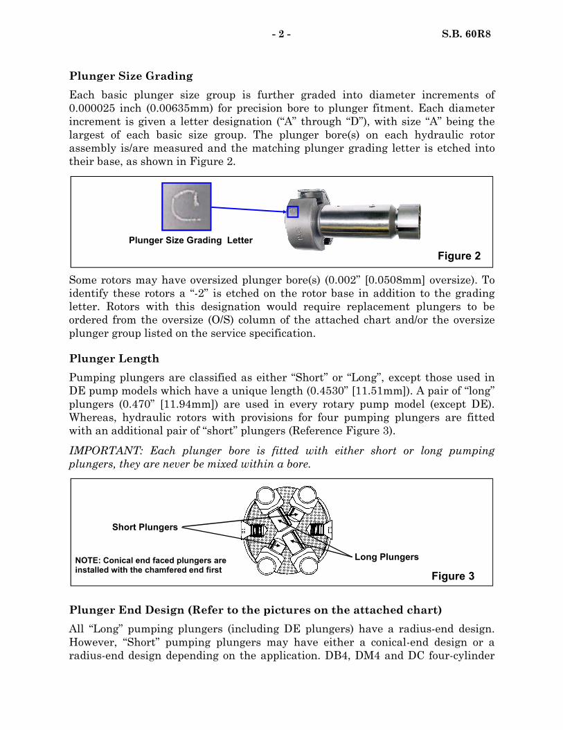
Plunger Size Grading
Each basic plunger size group is further graded into diameter increments of
0.000025 inch (0.00635mm) for precision bore to plunger fitment. Each diameter
increment is given a letter designation (“A” through “D”), with size “A” being the
largest of each basic size group. The plunger bore(s) on each hydraulic rotor
assembly is/are measured and the matching plunger grading letter is etched into
their base, as shown in Figure 2.
Some rotors may have oversized plunger bore(s) (0.002” [0.0508mm] oversize). To
identify these rotors a “-2” is etched on the rotor base in addition to the grading
letter. Rotors with this designation would require replacement plungers to be
ordered from the oversize (O/S) column of the attached chart and/or the oversize
plunger group listed on the service specification.
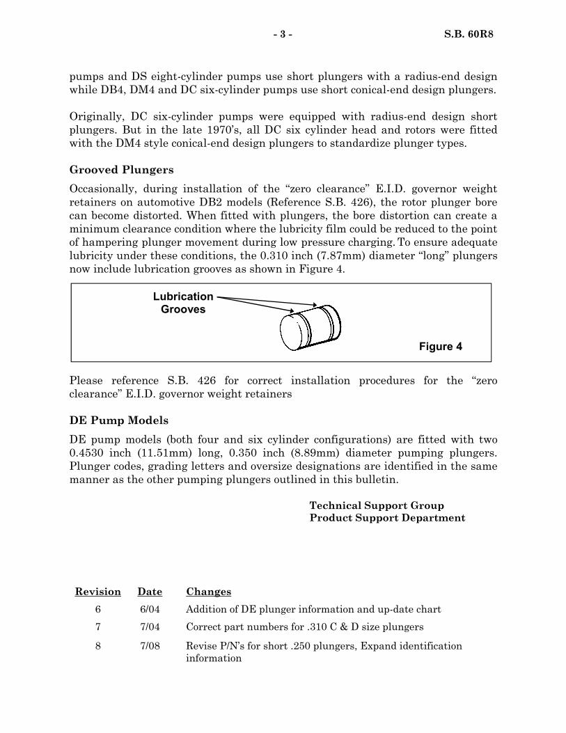
Plunger Length
Pumping plungers are classified as either “Short” or “Long”, except those used in
DE pump models which have a unique length (0.4530” [11.51mm]). A pair of “long”
plungers (0.470” [11.94mm]) are used in every rotary pump model (except DE).
Whereas, hydraulic rotors with provisions for four pumping plungers are fitted
with an additional pair of “short” plungers (Reference Figure 3).
IMPORTANT: Each plunger bore is fitted with either short or long pumping
plungers, they are never be mixed within a bore.
Figure 2
Plunger Size Grading Letter
Plunger End Design (Refer to the pictures on the attached chart)
All “Long” pumping plungers (including DE plungers) have a radius-end design.
However, “Short” pumping plungers may have either a conical-end design or a
radius-end design depending on the application. DB4, DM4 and DC four-cylinder
NOTE: Conical end faced plungers are installed with the chamfered end first
Figure 3
Long Plungers
Short Plungers
Revision Date Changes
6 6/04 Addition of DE plunger information and up-date chart
7 7/04 Correct part numbers for .310 C & D size plungers
8 7/08 Revise P/N’s for short .250 plungers, Expand identification
information
- 3 - S.B. 60R8
pumps and DS eight-cylinder pumps use short plungers with a radius-end design
while DB4, DM4 and DC six-cylinder pumps use short conical-end design plungers.
Originally, DC six-cylinder pumps were equipped with radius-end design short
plungers. But in the late 1970’s, all DC six cylinder head and rotors were fitted
with the DM4 style conical-end design plungers to standardize plunger types.
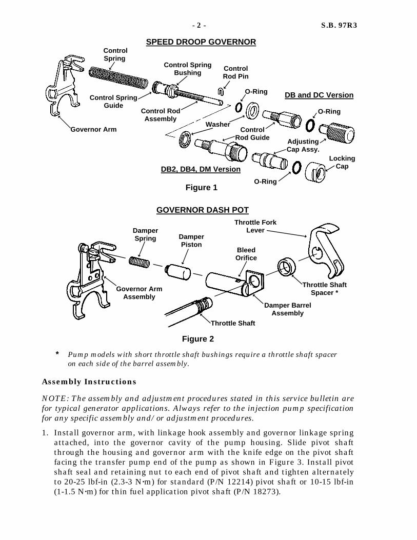
Grooved Plungers
Occasionally, during installation of the “zero clearance” E.I.D. governor weight
retainers on automotive DB2 models (Reference S.B. 426), the rotor plunger bore
can become distorted. When fitted with plungers, the bore distortion can create a
minimum clearance condition where the lubricity film could be reduced to the point
of hampering plunger movement during low pressure charging. To ensure adequate
lubricity under these conditions, the 0.310 inch (7.87mm) diameter “long” plungers
now include lubrication grooves as shown in Figure 4.
Please reference S.B. 426 for correct installation procedures for the “zero
clearance” E.I.D. governor weight retainers
DE Pump Models
DE pump models (both four and six cylinder configurations) are fitted with two
0.4530 inch (11.51mm) long, 0.350 inch (8.89mm) diameter pumping plungers.
Plunger codes, grading letters and oversize designations are identified in the same
manner as the other pumping plungers outlined in this bulletin.
Technical Support Group
Product Support Department
Lubrication Grooves
Figure 4

Pumping Plungers For Stanadyne Rotary Fuel Injection Pumps
Size Grade Std. O/S Std. O/S Std. O/S Std. O/S
Short Plungers
Long Plungers DE Plungers Conical-end Radius-end
.250
** A B C D
**11036 11037 11038 11039 11040
**11041 11042 11043 11044 11045
**21882 21883 21884 21885 21886
**21887 21888 21889 21890 21891
.270
** A B C D
**11046 11047 11048 11049 11050
**11051 11052 11053 11054 11055
**20250 20251 20252 20253 20254
**20255 20256 20257 20258 20259
**15709 15710 15711 15712 15713
**15959 15960 15961 15962 15963
.290
** A B C D
**11056 11057 11058 11059 11060
**11061 11062 11063 11064 11065
**20101 20102 20103 20104 20105
**20106 20107 20108 20109 20110
**18700 18701 18702 18703 18704
**18705 18706 18707 18708 18709
.310
** A B C D
**11066 *11067 *11068 *11069 *11070
**11071 *11072 *11073 *11074 *11075
**20593 20594 20595 20596 20597
**20598 20599 20600 20601 20602
**30254 30255 30256 30257 30258
**20359 20360 20361 20362 20363
.330
** A B C D
**11076 11077 11078 11079 11080
**11081 11082 11083 11084 11085
.350
** A B C D
**11086 11087 11088 11089 11090
**11096 11097 11098 11099 11100
**35187 35188 35189 35190 35191
**35192 35193 35194 35195 35196
.370
** A B C D
**11101 11102 11103 11104 11105
**11106 11107 11108 11109 11110
.390
** A B C D
**11111 11112 11113 11114 11115
**11116 11117 11118 11119 11120
.450
** A B C D
**14437 14438 14439 14440 14441
Not Available
* Grooved Design.
** Basic group number only. Do not order this number. Order only the number which corresponds with the letter code of
the required size and type
NOTE: If individual specifications call for
plunger part numbers not shown in this chart,
refer to Service Price List #99526 for possible
supersession information
Attachment to S.B. 60R8 May 16, 2008

DATE: February 5, 2001 SUPERSEDES S.B. 97R2 dated 10/28/90 SERVICE BULLETIN
NO: 97R3
Diesel Systems Division, Stanadyne Automotive Corp. 92 Deerfield Road, Windsor, CT 06095, U.S.A. Tel: (860) 525-0821; Fax: (860) 683-4581
Ever since the early 1950’s when it first made its appearance on diesel engines, the Stanadyne injection pump has been famous for its ability to provide stable governor regulation for the operation of power generation sets and other close governor regulation applications. The feature that has made this possible is the “speed droop governor”. Governor regulation of 3-5% can easily be attained with the speed droop governor and fine adjustments can be made while the engine is operating. Precise control of governor regulation is achieved by decreasing or increasing the effective length (and thereby the rate) of the governor control spring. The governor control spring is threaded onto an adjustable thimble arrangement, called the control rod assembly, and is adjusted by turning the external adjusting cap assembly. Turning the adjusting cap in the clockwise direction, viewed from the transfer pump end, shortens the control spring, making it less sensitive and thereby increasing governor regulation. Turning the adjusting cap in the counterclockwise direction increases governor sensitivity, thereby decreasing the governor regulation. Stanadyne currently has two versions of the speed droop governor in use in the field today as shown in Figure 1. DB and DC pump models use a knurled type adjusting cap which is retained in position by the transfer pump end plate. DM, DB4 and DB2 pump models utilize a slotted type adjusting cap which is retained by a locking cap. Servicing instructions for both types follow. Governor Dash Pot Some speed droop equipped applications require a governor dash pot assembly. The dash pot assembly aids in preventing engine surging and improves steady state performance by damping out oscillations of the governor control spring. The dash pot consists of a spring, piston, and barrel assembly with a bleed orifice. The device is anchored on the throttle shaft and is connected to the governor arm as shown in Figure 2.
SUBJECT: SPEED DROOP GOVERNOR ASSEMBLY AND ADJUSTMENT PROCEDURES
Assembly Instructions
NOTE: The assembly and adjustment procedures stated in this service bulletin are for typical generator applications. Always refer to the injection pump specification for any specific assembly and/or adjustment procedures.
1. Install governor arm, with linkage hook assembly and governor linkage spring attached, into the governor cavity of the pump housing. Slide pivot shaft through the housing and governor arm with the knife edge on the pivot shaft facing the transfer pump end of the pump as shown in Figure 3. Install pivot shaft seal and retaining nut to each end of pivot shaft and tighten alternately to 20-25 lbf-in (2.3-3 N·m) for standard (P/N 12214) pivot shaft or 10-15 lbf-in (1-1.5 N·m) for thin fuel application pivot shaft (P/N 18273).
- 2 - S.B. 97R3
SPEED DROOP GOVERNOR
Governor Arm
Control Spring
Control Spring Bushing
Control Spring Guide
Control Rod Pin
O-Ring
O-Ring
Control Rod Assembly
DB and DC Version
DB2, DB4, DM Version
Washer Control
Rod Guide Adjusting Cap Assy.
Locking Cap
* Pump models with short throttle shaft bushings require a throttle shaft spacer on each side of the barrel assembly.
Figure 2
Governor Arm Assembly
Throttle Shaft
Damper Barrel Assembly
Throttle Shaft Spacer *
Damper Spring Damper
Piston Bleed Orifice
Throttle Fork Lever
GOVERNOR DASH POT
Figure 1
O-Ring

2. For pump models with a governor dash pot, thread the damper spring onto the governor arm spring tab. Thread damper piston onto loose end of the damper spring and install governor arm assembly as described in Step No. 1. NOTE: Install head and rotor assembly and the metering valve assembly before proceeding to step No. 3.
3. Install control rod assembly, with end plate removed on DB and DC models, through threaded hole from inside of pump housing.
4. Slide control rod guide with washer in place (O-ring and washer on DB and DC models) over end of control rod assembly and thread into the housing finger tight while pushing down on the metering valve assembly. Tighten to 70-80 lbf-in (8-9 N·m).
5. Insert control rod pin into hole at the end of the control rod and position it as shown in Figure 3.
6. DB and DC pump models only Install adjusting cap seal into seal groove on control rod guide. Align roll pin slot in adjusting cap with control rod pin at end of control rod and slide over the seal on the control guide. Install transfer pump end plate and tighten the four end plate screws to 25-30 lbf-in (3-3.5 N·m).
7. DM, DB4, and DB2 models only Install adjusting cap seal into seal groove on the adjusting cap assembly. Align roll pin slot in adjusting cap with the control rod pin at the end of the control rod and slide into the control rod guide. Thread droop control locking cap onto control rod guide and tighten while supporting the control rod guide in place.
8. With control spring bushing threaded up against the control spring guide, as shown in Figure 3, thread the control spring five full turns onto the spring guide. NOTE: The standard number of spring turns onto the control spring guide is five (5) unless otherwise stated on the pump specification. Slip the free end of the control spring over the formed tabs of the governor arm with the bent-in end part of the control spring between the two tabs.
9. Reassemble the throttle and shut-off shaft assemblies and install a new shut-off cam or retaining clip (reference specification). NOTE: Check and reset linkage gap to specification, if necessary, before installing shut-off cam or retaining clip.
10. For pumps with a governor dash pot, slide the damper barrel assembly over the damper piston and slide throttle shaft assembly through the damper barrel, throttle shaft spacer and the throttle lever as shown in Figure 2. NOTE: Pump models with short throttle shaft bushings require a throttle shaft spacer on each side of the barrel assembly.
11.With the throttle shaft assembly in the low idle position and the governor control spring relaxed, the forked end of the throttle lever should straddle and engage the flats on the control rod bushing. Adjust the low idle screw until the forks of the throttle lever make contact with the flats on the control guide
- 3 - S.B. 97R3

bushing, then back the screw out 1/4 of a turn. This will ensure no preload exists on the speed droop spring. Tighten the low idle lock nut to 30-35 lbf-in (3.5-4 N·m).
12. Turn adjusting cap counterclockwise (from the transfer pump end) to end of adjustment, then turn clockwise 1/16 of a turn. This prevents binding between the throttle shaft lever and the control rod bushing. The speed droop assembly is now positioned for minimum droop.
TEST BENCH CALIBRATION PROCEDURES Speed droop equipped pumps are calibrated in the same manner as other governor application pumps with the exception of low idle and speed droop adjustments. Provided below are notes on low idle screw and speed droop adjustment procedures. Low Idle Screw Adjustment The position of the low idle screw is set during assembly of the speed droop and establishes the necessary relationship of the internal components. Engine idle speed for most applications is merely a function of the governor spring rate and
- 4 - S.B. 97R3
High Idle Adjustment Screw
Low Idle Adjustment Screw
Five Full Dead Coils onto Control Rod Bushing
(Unless otherwise stated on the pump specification)
No gap permissible between the Control Spring Bushing and Control
Spring Guide during Assembly Pivot Shaft Knife
Edge
Adjust Low Idle Screw Until Throttle Lever Contacts
Control Rod Bushing and Back-out 1/4 of a Turn
Metering Valve
1 2 3 4 5 0
Dead Coil Count
Figure 3

regulation, and will generally be in the range of 800 – 1100 RPM. On some applications where the generator set manufacturer desires a higher idle speed than this, it is permissible to adjust the low idle screw in to increase idle speed. Never back out the low idle screw on a speed droop equipped pump or disengagement of the throttle lever from the guide bushing could result. Speed Droop Adjustment Refer to the individual pump specification to determine the amount of adjustment required and where in the calibration sequence it occurs. Speed droop adjustments can be prior to, during or after the calibration is completed, depending on the engine manufacturer’s preference. All pump settings are done with the speed droop in the minimum position when there is no reference of speed droop adjustment on the specification. NOTE: Since high idle speed and final droop adjustments are made on the engine, it is necessary to reset both the high idle screw and the speed droop adjusting cap back to the original calibration set points before performing as received pump calibration checks. Please reference the injection pump specification for exact instructions. ON-ENGINE SPEED DROOP ADJUSTMENT PROCEDURE NOTE: Always refer to the engine manufacturer’s manual for exact setting procedures. These instructions are for typical applications only. 1. Start engine and apply approximately 50% load until it reaches operating
temperature. Note: If excessive surging occurs during the warm-up period, turn the speed droop adjusting cap clockwise until surging stops.
2. When the engine has reached operating temperature, position throttle to attain
full load speed (e.g., 1800 RPM) and apply 100% load. Adjust the throttle if necessary to obtain satisfactory 100% load performance.
3. Remove load and check for specified no-load speed or frequency. If incorrect,
adjust speed droop adjusting cap slightly (clockwise for increased droop or counterclockwise for less droop). If surging exists upon removing the load, turn the adjusting cap clockwise to eliminate. NOTE: Whenever speed droop adjustments are made, accompanying throttle position adjustments will also be necessary.
4. Recheck 100% load and no-load performance and readjust as necessary.
Technical Support Group Product Support Department
- 5 - S.B. 97R3
Revision Date Changes 3 12/00 Added dead coil count information


NO: 108RlO
STANADYNE ..- lLE!mim )-- I
SERVICE BULLETIN DATE: November 22,1995 SUPERSEDES: S.B. 108R9 dated 4/l/89
I?.
SUBJECT: ELECTRICAL SHUTOFF SOLENOID SERVICE PROCEDURES
MODELS AFFECTED: D SERIES FUEL INJECTION PUMPS (EXCEPT DS)
General Information Electrical shutoff solenoids are included in many Stanadyne pump applications to accomplish engine shutdown by interrupting the fuel delivery to the engine. Their use is desirable for several reasons, including operator convenience, anti-theft protection, and elimination of bulky cables and linkages. An important safety feature of the Stanadyne electric shutoff solenoid is its ability to close the metering valve and shut off fuel delivery independent of governor action.
Location
ETR Solenoid Figure la
Note Arm/ Location
ETSO Solenoid Figure 1 b
Two basic types of electrical shutoff (ESO) devices are used in Stanadyne injection pumps as shown in Figures la and lb. Energized to run (ETR) solenoids are the most common. They are energized continuously while the engine is running and when de-energized, will cause the engine to shut off.
Energized to shutoff (ETSO) solenoids (Figure lb) are used less frequently_ These are designed to be energized only momentarily when engine shutdown is desired.
Dilesel Systems Division, Stanadyne Automotive Corp. 92 Deerfield Road, Windsor, CT 06095, USA Tel: (203) 525-0821; Telex: 99218; Telecopy: (203) 525.4215

-2- S. B. 108RlO
NOTE: Electric shutoff solenoids rely on the flow of fuel through the pump and back to the fuel tank to dissipate heat generated by the coil when energized. Therefore, an ES0 coil may be damaged if left energized for an extended period without the engine operating and a supply of fuel flowing around the coil. For this reason, a spring-loaded or push-button type switch must be used in ETSO applications. Similarly, ETR solenoids should not be left energized for more than short periods of time when the engine is not running or when the pump housing is not full of fuel.
ETR Versus ETSO Solenoids All Stanadyne E.S.O.‘s are now plunger-type solenoids rather than the older “flapper type” for greater debris resistance and longer life. All Energized to Run ESO’s are now of the “high force” type which utilize a longer coil for increased pull in and drop out forces Fig. 2a). Since Energized to Shutoff solenoids are reversed in the governor cover, the longer high force type of solenoid cannot be used due to interference with the throttle shaft. As a result, ETSO solenoids continue to be the “standard force” type (Fig. 2b).
ES0 part numbers and coil voltage are stamped on the frame (Reference the Application and Supersession Chart on page 10). Solenoid date codes (such as B83 or 1186) appear either on the frame or on the coil encapsulation.
High Force ES0 (ETR Applications)
Figure 2a
Grounding Devices
Standard Force ES0 (ETSO Application)
Figure 2b
ESO’s are grounded by means of a sheet metal strap, P/N 20951, mounted between one solenoid terminal and the adjacent governor cover retaining screw as shown in Figure 3a. Refer to the individual specification to determine which terminal is grounded for a given application. The 20951 grounding strap is sold separately as well as being provided in solenoid mounting and grounding kit 26431. It should be used on all applications where the front governor cover screws are accessible. Grounding wire 18491 (Figure 3b) is supplied in Kit 21710 for old style aneroid applications or as needed when interference of the strap with an accessory such as an aneroid bracket exist.
‘L-H’
ii

-3- S. B.IlOSRlO
CAUTION: Prevent strap from twisting when tlghtenmg hold-down screws
Terminal Contact Locknuts
Contact Nuts
Figure 3a Figure 3b
Serviceable Solenoid Parts And Servicing Since the introduction of plunger-type solenoids, Stanadyne does not recommend solenoid arm travel or spring force adjustments of any type,. An electric shutoff solenoid’s ability to pass the test specification criteria should be your guide as to whether solenoid replacement is necessary. Servicmg of solenoids should be limited to blowing off accumulated debris with compressed air and wiping with a clean cloth. If plunger stickiness is encountered, the solenoid may be carefully disassembled, cleaned and reassembled. Replacement parts are limited to springs, spring sleeves and insulating tubes should these become unserviceable or lost during servicing. Available part numbers are as follows:
P/N Description 12480 Shutdown Coil Arm Spring 12481 Shutdown Coil Arm Spring 16396 Coil Arm Spring Sleeve 23190 Insulating Tubes
Usage ETR ESO’s ETSO ESO’s All ESO’s All ESO’s
Installation Of Solenoid To Governor Cover Since ESO’s are not provided with any mounting or grounding hardware except for the two P/N 23190 insulating tubes, Stanadyne provides an ES0 mounting and grounding kit, P/N 26431, which consists of the following parts:
P/N 12049 12500 12519 14760 18493 18501 20951
Description Terminal Contact Lock Washer
Q;
Terminal Insulating Washer 3 Terminal Contact Nut 3 Terminal Contact Lock Nut 3 Cover Screw Lockwasher 1 Terminal Contact Washer 3 Terminal Grounding Strap 1

-4- S. B. 108RlO
This kit contains enough hardware to mount and ground both the ES0 solenoid and a Housing Pressure Cold Advance (HPCA) solenoid (if the pump is so equipped) in the governor cover. Solenoid terminals and terminal insulators must also be purchased separately - refer to the individual specifications for part numbers.
Figure 4
A typical ES0 installation is shown in Figure 4. Refer to the individual specification for the exact component arrangement. Tighten retaining nuts to lo-15 lb.-inches. (1.1-1.7 Nm) exercising care not to twist the grounding strap.
Cover Modifications - Energized To Run (ETR) Solenoids When it becomes necessary to replace an old-style flapper-type solenoid with a current high force plunger-type, it may be necessary to replace rework the governor cover slightly in two areas as shown in Figure 5 to prevent interference. One source of interference is due to a slight raised area on the
Relieve inside corners of cover if the hiah force
solenoid frame-does not rest flush with the cover
Figure 5
Chamfer to revent interference wit R the raised area of the solenoid frame
-- II .125”(3.2mm)

-5- S. B. IO8RlO
solenoid arm pivot area of plunger-type solenoid frames. All governor covers now have these chamfers cast in but if a plunger-type solenoid is being installed in an older cover without the chamfers, the interference between the raised area on the frame and the cover could render the solenoid inoperable upon installation. It is recommended that the chamfer be filed or machined into the cover at the edge of the rear cutout as shown in Figure 5 to the dimensions shown any time a plunger-type solenoid is installed into a governor cover that does not have the chamfers already cast in. The other possible area of interference is in the inside, front corners of the cover due to the additional length of the high force solenoid frame. Again, newer style covers are relieved in this area but if a high force solenoid is being installed in an older cover and it does not fit flush to the underside of the cover, it will1 be necessary to relieve the corners of the cover to provide clearance.
Cover Modifications - Energized To Shutoff (ETSO) Solenoids
Frame Interference When it becomes necessary to install a plunger-type, Energized to Shutoffl (ETSO) solenoid into an older governor cover, it will be necessary to rework the cover as shown in Figure 6 in order to ensure free travel of the solenoid arm. As mentioned previously, the chamfer at the edge of the front cutout is needed to prevent interference with the raised area of the plunger-type solenoid frame design. The chamfer can be filed or machined to the dimensions shown. Current production covers have the chamfer cast in. NOTE: Failure to relieve the cover in this manner could result in the plunger-type solenoid being rendered inoperable upon installation.
Remove Material to Ailo,w,~~;l Arm
Chamfer to Prevent
Interference
Arm Travel Figure 6
If after ETSO solenoid installation, incomplete fuel shutoff is encountered during pump calibration, it may be due to the upper part of the arm contacting the inside of the cover before the plunger has pulled in completely.

-6- S. B. 108RlO
If this occurs, the cover may be reworked as shown in Figure 6. However, whenever a cover is reworked as shown in Figure 6 to accommodate an ETSO solenoid, the increased arm travel may, under certain circumstances, result in the ETSO solenoid arm “jumping over” the linkage hook resulting in an “Intermittent Shutoff’ and/or “NO Start” complaint (Ref. Figure 7).
Figure 7
To prevent this condition, Stanadyne has begun producing ETSO solenoids (P/N’s 26921 and 26922) with the arm lengthened by lmm (0.040 inches). These ESO’s can be identified by the absence of the two dimples on the solenoid arm as shown below in Figure 8.
Note lack of dimples
Previous Design Current Design
Figure 8
When installing an ETSO solenoid with the shorter arm into a cover relieved as shown in Figure 6, it will be necessary to install two extra insulating washers, P/N 12500 on the solenoid terminals between the solenoid frame and the cover as shown in Figure 9. This will position the solenoid approximately -040 inches(1 mm) deeper in the pump housing.
IMPORTANT: Never install the two extra PIN 12500 insulating washers between the cover and the solenoid frame on ETSO solenoids with the lengthened arm.

S. B. X08RlO
lnsulatin Tubes
Extra pair of 12500 Insulating Washers
Figure 9
Installation Of Governor Cover To Pump Extreme care must be taken when assembling a governor cover and ETR IESO solenoid to a pump. It is possible to locate the pivot arm on the wrong side of the linkage hook tab, thus “locking” the linkage hook and metering valve in the “full run” position, blocking all governor action. If this condition exists when the pump is installed on the engine, the engine may accelerate to dangerously high speeds upon starting. The recommended method of ensuring proper installation of a governor cover containing an ETR shutoff solenoid is to use service tool 26528 as shown below in Figure 10. With the tool installed as shown, place the cover in position on the pump housing. Twist the 26528 tool to release it and slide it out from between the cover and the housing taking care not to dislodge or damage the cover seal.
Figure IO
Service tool 26528 is designed to be used with any type of energized to run solenoid (standard or high force) to ensure proper cover installation and should be used any time a governor cover with and ETR ES0 is installed on a pump. However, in the event that tool 26528 is not available, the governor cover can be installed as follows.

-8- S.B.lOSRlO
1.
2.
3.
Remove the three governor cover screws and washers and set aside.
Move the governor cover down towards the top of the pump from a position further toward the drive shaft end than its final assembled position as shown in Figure 11 to ensure the pivot arm is positioned on the proper side of the linkage hook.
Just before the cover seal touches the housing, slide the cover into alignment, install the cover screws and washers, and tighten screws to 35-45 lbf.-inches (4.0-5.1 Nm).
Figure 11
Bench Test Procedures - Energized to Run Solenoids Many pump specifications for ETR applications now call for a pull-in voltage check. To perform this check, first set the voltage at the ES0 terminals by connecting the ES0 to the variable voltage source and connecting a separate voltmeter (preferably digital) to the ES0 terminals as shown in Figure 12. Turn the voltage source on and adjust the variable voltage supply to the pull-in voltage requirement called for on the individual specification (usually 8.8 or 10.0 volts on 12 volt systems and 17.6 volts on 24 volt systems), then remove the voltmeter. Once the voltage source is “calibrated” to the correct pull-in voltage, it will only be necessary to turn the voltage source off and on to perform pull-in tests. Do not adjust the voltage up to the desired level to perform the pull-in test - merely turn the voltage supply off and then back on to perform this test. Check the operation of the ES0 solenoid at the speeds and throttle position(s) indicated on the individual specification. NOTE: Do not attempt to check ETR solenoid operation with the governor cover removed from the pump as the governor linkage spring aids solenoid operation.
Voltmeter _ Variable
- sonic
L’
i/
Grounding Strap Figure 12

-9- S.B.lOSRlO
Bench Test Procedures - Energized to Shutoff Solenoids An ES0 coil of one half system voltage is normally specified for ETSO applications. This is because these solenoids are energized only momentarily to shut down the engine and because these solenoids have to overcome the linkage spring force instead of being assisted by it.
Use the voltage called for on the individual specification when testing ETSO solenoids to avoid damaging the coil. If a test voltage isn’t specified, use the coil voltage. Only leave an ETSO solenoid energized long enough to check for fuel shutoff and never leave an ETSO solenoid energized for an extended period of time with voltage greater than coil voltage applied.
Mechanical Override Device A special accessory is used in some “D” series pump applications with ETR solenoids. If an electrical failure occurs or the necessary voltage is unavailable to power the solenoid, the solenoid arm can be locked mechanically in the “run” position to permit emergency operation.
The override consists of a guide and rod assembly mounted in the rear of a special governor cover, which aligns the rod with the solenoid pivot arm (Figure 13). When the rod is pushed in it moves the ES0 pivot arm to the energized position leaving the linkage hook free to operate. To accomplish fuel shutoff, the override rod is pulled out.
To disassemble, remove the governor cover. Remove the lock ring and pull. the control rod from the cover. Loosen and remove the guide, washer and seal. To assemble, install the washer and seal onto the guide and thread into cover. Insert rod and secure with a new lock ring from inside.
Guide
Control Rod -
Applications The following is a compilation of the high force ES0 part numbers and the standard force solenoid part numbers and the individual solenoids and kits which they supersede.

-lO- S. B. 108RlO
ELECTRIC SHUTOFF SOLENOID
APPLICATION AND SUPERSESSION INFORMATION
Superseded Standard Force ES0 Part Numbers
Coil Voltage Current ES0 P/N and Application ESO’s ES0 Kits
26214 12V ETR 21323 22146 (High force) 21584 22146
21806 22149 22314 27647 22315 24145 27360
26922 (Standard force)
12V ETSO Coil (used with 24V system voltage)
21805 22262 22261
26921 (Standard force)
6V ETSO Coil (used with 12V system voltage)
18694
26387 24V ETR 21807 22147 (High force) 21997 24164
24149 24164 27011 27012
22113 32V ETR 18693 22260
Technical Support Group Product Support Department

DATE: July 19, 2005 Supersedes: S.B. 125R5 dated 4/23/02
SERVICE BULLETIN
Stanadyne Corporation 92 Deerfield Road, Windsor, CT 06095, U.S.A. Tel: (860) 525-0821; Fax: (860) 683-4581; www.stanadyne.com
SUBJECT: FIELD CONVERSION FOR OPERATION WITH REDUCED
LUBRICITY FUELS
Stanadyne pumps are tpically designed to operate with Number 2 Diesel Fuel (DF-2)
which provides no more than a 460 micron wear scar diameter when tested using a
High Frequency Reciprocating Rig per ISO 12156-1 and 2.
Stanadyne has compiled the following information for our service network to allow for
field conversions of Stanadyne mechanical fuel injection pumps for operation with
fuels having reduced lubricity. Such fuels would typically include DF-1, Jet fuels,
Kerosene, etc. as noted in the chart below.
Stanadyne recommends the use of special transfer pump and drive components to
reduce wear and extend the life of the pump when operated with reduced lubricity
fuels. In addition to the transfer pump and drive components, specially plated
governor components are recommended for applications which are equipped with
speed droop governors when operating with these fuels.
Stanadyne has established the following guidelines for operation of our fuel injection
pumps with standard and the special components. Whenever a pump is converted for
reduced lubricity fuel operation, it is imperative that the end user understands that
the special components were developed for operation with fuels listed within the
recommended and acceptable categories. Fuels listed within the emergency category
such as JP-4, should be used as such, on an emergency basis only.
FUEL USAGE WITH STANDARD COMPONENTS
FUEL USAGE WITH SPECIAL REDUCED LUBRICITY COMPONENTS
Recommended DF-2, No. 2-D DF-2, No. 2-D, DF-1, No. 1-D
Acceptable DF-1*, No. 1-D*, No. 4-D Jet-A, Jet A-1, DF-A, JP-5, JP-7, JP-8
Emergency only Jet-A, Jet A-1, DF-A, JP-4, JP-5, JP-7, JP-8, TS
JP-4, TS
* Diesel fuel grade No. 1 is only acceptable for use with standard components when
ambient temperatures are below 32° F (0° C).
NOTE: Reference the Stanadyne Service Policies and Procedures Manual 99666 for
information regarding the use of Biodiesel fuels.
NO: 125R6

- 2 - S.B. 125R6
NOTE: Home heating oils commonly carry the same No. 1 and No. 2 grade
designations as Diesel fuel and are sometimes used interchangeably with those
grades of Diesel. Some home heating oils, do not contain the additives that are
in road fuels and could affect proper engine operation. It is also illegal in many
area to utilize these oils for over-the-road use when their cost does not include
applicable road taxes.
Use the following table to determine which part changes are required to
implement field conversions for reduced lubricity fuel use. Compare the
individual pump specification to the table in order to identify which standard
components have a reduced lubricity replacement part .
Remove Install Description
Model Type
DB DB2 DB4 DM
20511 372681 Transfer Pump Blades (was 20803) X X X X
20512 374491 Transfer Pump Blades (was 20804) X X X X
34758 372651 Transfer Pump Blades (was 33499) X X
21232 374471 Transfer Pump Liner (was 22988) X X X
11620 29709 Governor Thrust Washer X X
23272 20222 Governor Thrust Washer X X
19860 23856 Governor Thrust Washer X X
21522 24691 Drive Shaft Spring Washer X
26468 26358 Drive Shaft Thrust Washer X
26469 26361 Shaft Retaining Ring X
10213 29138 Drive Shaft X X
21519 28573 Drive Shaft X
23364 24108 Drive Shaft X
23452 26238 Drive Shaft X
26179 26238 Drive Shaft X
26386 26538 Drive Shaft (Ref. S.B. 419) X
28825 23820 Drive Shaft X
29183 27639 Drive Shaft X
30941 30940 Drive Shaft X
30500 31325 Drive Shaft X
19870 33817 Rotor Retainer2 X X
32859 33818 Rotor Retainer2 X X
34759 372671 Transfer Pump Blades (was 33501) X X
16753 374521 Transfer Pump Liner (was 18658) X
33886 33925 Drive Shaft X
34828 32901 Drive Shaft X
24623 26538 Drive Shaft (Ref. S.B. 419) X
Conversion Parts for Reduced Lubricity Fuel Usage
1 These transfer pump components are made from a different material and supersede the
components previously specified for reduced lubricity fuels. They are not compatible with the
previous components and must therefore not be intermixed (Reference Service Bulletin 304R9).
2 Part numbers 33817 and 33818 can be used only in pump models with pressure compensating
transfer pumps (Reference S.B. 444A). These rotor retainers have a notch on the outside diameter
to distinguish them from P/N’s 19870 and 32859.
- 3 - S.B. 125R6
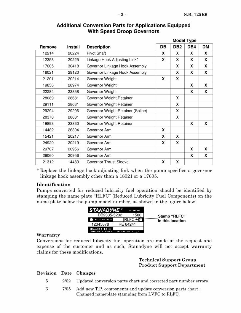
Additional Conversion Parts for Applications Equipped With Speed Droop Governors
Remove Install Description
Model Type
DB DB2 DB4 DM
12214 20224 Pivot Shaft X X X X
12358 20225 Linkage Hook Adjusting Link* X X X X
17605 30418 Governor Linkage Hook Assembly X X X
18021 29120 Governor Linkage Hook Assembly X X X
21201 20214 Governor Weight X X
19858 28974 Governor Weight X X
22284 23858 Governor Weight X X
28089 28681 Governor Weight Retainer X
29294 29296 Governor Weight Retainer (Spline) X
28370 28681 Governor Weight Retainer X
19893 23860 Governor Weight Retainer X X
15421 20217 Governor Arm X X
24929 20219 Governor Arm X X
29060 20956 Governor Arm X X
21312 14483 Governor Thrust Sleeve X X
29707 20956 Governor Arm X X
14482 26304 Governor Arm X
29111 28681 Governor Weight Retainer X
* Replace the linkage hook adjusting link when the pump specifies a governor
linkage hook assembly other than a 18021 or a 17605.
Identification
Pumps converted for reduced lubricity fuel operation should be identified by
stamping the name plate “RLFC” (Reduced Lubricity Fuel Components) on the
name plate below the pump model number, as shown in the figure below.
Warranty
Conversions for reduced lubricity fuel operation are made at the request and
expense of the customer and as such, Stanadyne will not accept warranty
claims for these modifications.
Technical Support Group
Product Support Department
Revision Date Changes
5 2/02 Updated conversion parts chart and corrected part number errors
6 7/05 Add new T.P. components and update conversion parts chart .
Changed nameplate stamping from LVFC to RLFC.
DB2335-5202 1500
12345678
RLFC
RE 64241
Stamp “RLFC” in this location

Stanadyne Corporation 92 Deerfield Road, Windsor, CT 06095, U.S.A. Tel: (860) 525-0821; Fax: (860) 683-4581; www.stanadyne.com
NO: 225R7 DATE: December 10, 2009
SERVICE BULLETIN
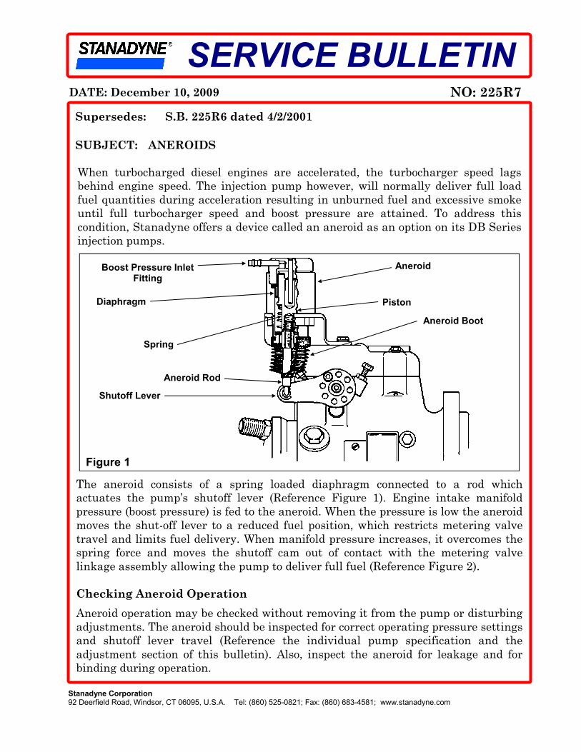
When turbocharged diesel engines are accelerated, the turbocharger speed lags
behind engine speed. The injection pump however, will normally deliver full load
fuel quantities during acceleration resulting in unburned fuel and excessive smoke
until full turbocharger speed and boost pressure are attained. To address this
condition, Stanadyne offers a device called an aneroid as an option on its DB Series
injection pumps.
The aneroid consists of a spring loaded diaphragm connected to a rod which
actuates the pump’s shutoff lever (Reference Figure 1). Engine intake manifold
pressure (boost pressure) is fed to the aneroid. When the pressure is low the aneroid
moves the shut-off lever to a reduced fuel position, which restricts metering valve
travel and limits fuel delivery. When manifold pressure increases, it overcomes the
spring force and moves the shutoff cam out of contact with the metering valve
linkage assembly allowing the pump to deliver full fuel (Reference Figure 2).
Checking Aneroid Operation
Aneroid operation may be checked without removing it from the pump or disturbing
adjustments. The aneroid should be inspected for correct operating pressure settings
and shutoff lever travel (Reference the individual pump specification and the
adjustment section of this bulletin). Also, inspect the aneroid for leakage and for
binding during operation.
SUBJECT: ANEROIDS
Supersedes: S.B. 225R6 dated 4/2/2001
Figure 1
Diaphragm
Boost Pressure Inlet Fitting
Shutoff Lever
Aneroid
Aneroid Rod
Spring
Piston
Aneroid Boot

- 2 - S.B. 225R7
Connect a filtered, regulated and measurable air pressure source to the boost
pressure inlet fitting. NOTE: Operating pressures are very low, an accurate gage
with a range of 0 - 30 p.s.i. (0 – 207 kPa), calibrated in 0.5 p.s.i. (3.5 kPa)
increments is recommended. Refer to the individual pump specification for the
operating pressure and shutoff lever travel settings for each application. If service
or adjustments are necessary, refer to the appropriate section of this bulletin.
Service and Replacement
The aneroid is a non-serviceable sealed component. If aneroid replacement is
required, it must be replaced as an assembly. Originally sold separately without
the aneroid rod and boot, a new family of aneroid assemblies was released in 2000
that included the 19776 aneroid rod and a 16809 aneroid boot (Reference Figure 4).
Since the introduction of the complete assemblies, the aneroid has undergone some
internal design changes and the addition of a lock nut to the aneroid rod on some
assemblies (Reference Figure 3 & 4). The new complete aneroid assemblies now
supersede all previous aneroid assemblies as shown in the table below.
Always refer to the individual pump model service specification to determine which
aneroid to use. NOTE: The boost pressure inlet fittings (P/N’s 31104 and 40587)
are now available for service replacement, as shown in Figures 3 & 4.
3
Shutoff Cam Rotates Against Metering Valve Linkage Assembly
4
Fuel Delivery Limited by Metering Valve
Position
1
Intake Manifold Air Pressure
2
Aneroid Rod Extends and Retracts
Figure 2
Aneroid Assemblies
Current Supersedes
34995 18232, 34660
35222 18423, 34661
35223 33594, 34662
35224 33594, 34663
40586 —
- 3 - S.B. 225R7
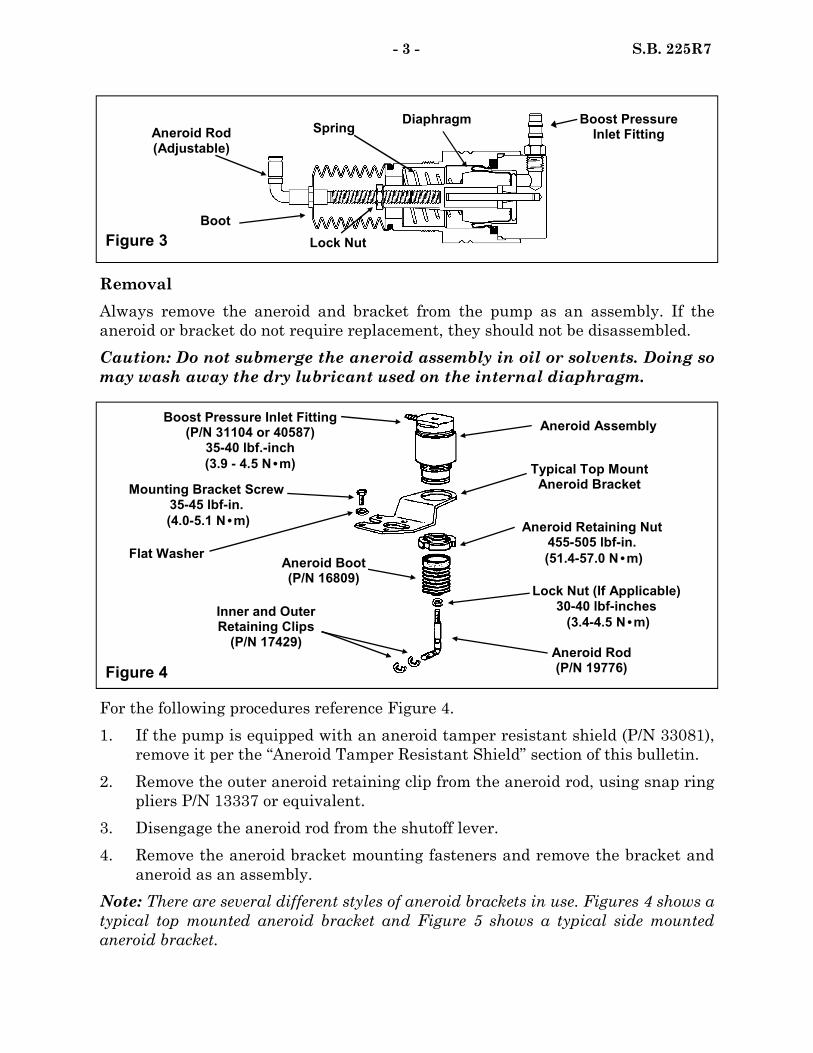
Removal
Always remove the aneroid and bracket from the pump as an assembly. If the
aneroid or bracket do not require replacement, they should not be disassembled.
Caution: Do not submerge the aneroid assembly in oil or solvents. Doing so
may wash away the dry lubricant used on the internal diaphragm.
For the following procedures reference Figure 4.
1. If the pump is equipped with an aneroid tamper resistant shield (P/N 33081),
remove it per the “Aneroid Tamper Resistant Shield” section of this bulletin.
2. Remove the outer aneroid retaining clip from the aneroid rod, using snap ring
pliers P/N 13337 or equivalent.
3. Disengage the aneroid rod from the shutoff lever.
4. Remove the aneroid bracket mounting fasteners and remove the bracket and
aneroid as an assembly.
Note: There are several different styles of aneroid brackets in use. Figures 4 shows a
typical top mounted aneroid bracket and Figure 5 shows a typical side mounted
aneroid bracket.
Figure 3
Boost Pressure Inlet Fitting
Lock Nut
Diaphragm
Boot
Aneroid Rod (Adjustable)
Spring
Typical Top Mount Aneroid Bracket
Aneroid Assembly
Figure 4
Aneroid Retaining Nut 455-505 lbf-in.
(51.4-57.0 N•m) Flat Washer
Mounting Bracket Screw 35-45 lbf-in.
(4.0-5.1 N•m)
Aneroid Boot (P/N 16809)
Aneroid Rod (P/N 19776)
Inner and Outer Retaining Clips (P/N 17429)
Boost Pressure Inlet Fitting (P/N 31104 or 40587) 35-40 lbf.-inch
(3.9 - 4.5 N•m)
Lock Nut (If Applicable) 30-40 lbf-inches
(3.4-4.5 N•m)

Installation
1. Install the aneroid and mounting bracket assembly on the pump. For a top
mounting bracket (Figure 4), tighten the screws to 35-45 lbf-in. (4.0-5.1 N•m).
For a side mounted bracket (Figure 5), tighten the rear governor cover screw
to 35-45 lbf-in. (4.0-5.1 N•m) and tighten the nut on the head locking screw
stud to 70-80 lbf-in. (7.9-9.0 N•m).
- 4 - S.B. 225R7
2. Do not attach the aneroid rod to the pump shutoff lever at this time. Pump
calibration should be performed with the aneroid rod disconnected and the
shutoff lever held in the “Run” position. Aneroid adjustments should be
performed following pump calibration, as outlined in the Adjustment Section
of this bulletin.
Aneroid/Bracket Disassembly and Reassembly
While the aneroid and its bracket should normally be left assembled, should either
component require replacement, disassembly and reassembly may be performed as
follows:
1. Clamp the aneroid bracket in a vise.
2. Remove the boot from the aneroid body assembly, unscrew and remove the
aneroid rod from the aneroid piston. If equipped, the lock nut must be
loosened prior to removing the aneroid rod from the aneroid piston. Wrench
flats have been added to the aneroid piston to prevent the piston from
rotating.
3. Remove the aneroid body retaining nut using the P/N 18031 Aneroid
Retaining Nut Wrench and remove the aneroid from the bracket.
Note: The 17954 aneroid retaining nut has been superseded by P/N 34303. The
34303 aneroid retaining nut is thicker and has a large lead-in chamfer to reduce
the possibility of thread damage during assembly.
Figure 5
Flat Washers
Rear Governor Cover Screw 35-45 lbf-in.
(4.0-5.1 N•m)
Nut, Head Locking Screw Stud 70-80 lbf-in.
(7.9-9.0 N•m)
Head Locking Screw 180-200 lbf-in.
(20.3-24.9 N•m)
Aneroid Assembly
Side Mount Aneroid Bracket
Aneroid Retaining Nut
Aneroid Rod
4. To reassemble, secure the bracket in a vise and install the aneroid body into
the bracket. Position the aneroid inlet fitting according to the position
indicated on the individual pump specification.
5. Assemble the aneroid retaining nut to the aneroid body and tighten the nut to
455-505 lbf-in. (51.4-57.0 N·m) using tool 18031.
6. Attach the boot to the aneroid rod and thread the rod (with the lock nut
installed on the aneroid rod, if equipped) into the aneroid piston. Lightly
bottom the aneroid rod in the piston and then back it out approximately three
(3) turns, leaving the lock nut loose until the final aneroid adjustments are
made. Install the aneroid and bracket assembly as outlined in the Installation
section of this bulletin.
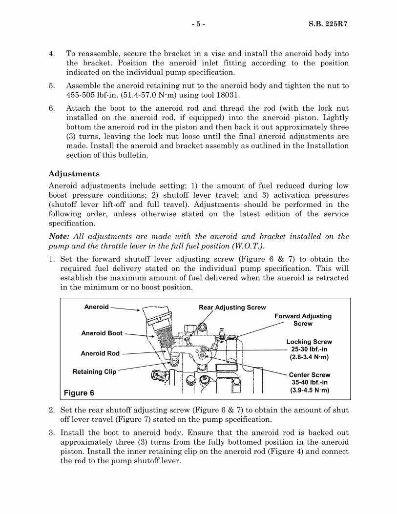
Adjustments
Aneroid adjustments include setting; 1) the amount of fuel reduced during low
boost pressure conditions; 2) shutoff lever travel; and 3) activation pressures
(shutoff lever lift-off and full travel). Adjustments should be performed in the
following order, unless otherwise stated on the latest edition of the service
specification.
Note: All adjustments are made with the aneroid and bracket installed on the
pump and the throttle lever in the full fuel position (W.O.T.).
1. Set the forward shutoff lever adjusting screw (Figure 6 & 7) to obtain the
required fuel delivery stated on the individual pump specification. This will
establish the maximum amount of fuel delivered when the aneroid is retracted
in the minimum or no boost position.
- 5 - S.B. 225R7
2. Set the rear shutoff adjusting screw (Figure 6 & 7) to obtain the amount of shut
off lever travel (Figure 7) stated on the pump specification.
3. Install the boot to aneroid body. Ensure that the aneroid rod is backed out
approximately three (3) turns from the fully bottomed position in the aneroid
piston. Install the inner retaining clip on the aneroid rod (Figure 4) and connect
the rod to the pump shutoff lever.
Figure 6
Aneroid Rear Adjusting Screw
Aneroid Boot
Aneroid Rod
Retaining Clip Center Screw 35-40 lbf.-in
(3.9-4.5 N·m)
Locking Screw 25-30 lbf.-in
(2.8-3.4 N·m)
Forward Adjusting Screw
4. Connect the regulated air pressure source to the aneroid inlet. Cycle the
pressure between 0 and 7 p.s.i. (0 – 48.3 kPa), a minimum of three (3) times,
and check for smooth motion.
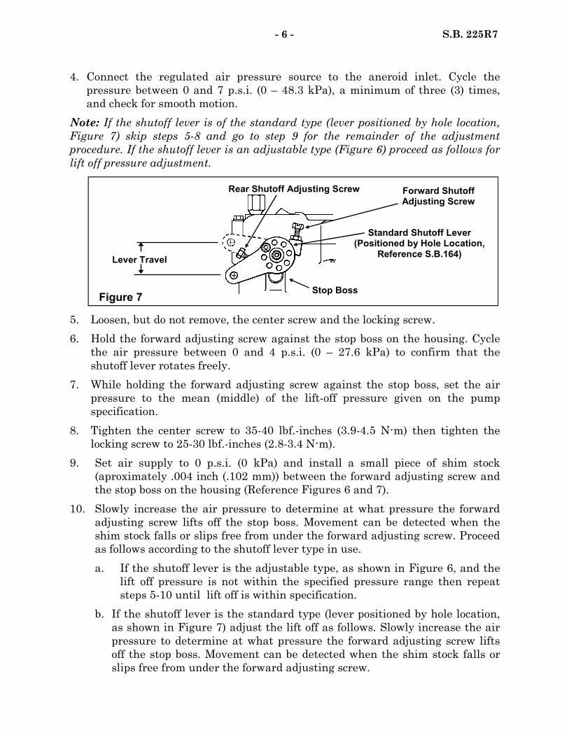
Note: If the shutoff lever is of the standard type (lever positioned by hole location,
Figure 7) skip steps 5-8 and go to step 9 for the remainder of the adjustment
procedure. If the shutoff lever is an adjustable type (Figure 6) proceed as follows for
lift off pressure adjustment.
- 6 - S.B. 225R7
5. Loosen, but do not remove, the center screw and the locking screw.
6. Hold the forward adjusting screw against the stop boss on the housing. Cycle
the air pressure between 0 and 4 p.s.i. (0 – 27.6 kPa) to confirm that the
shutoff lever rotates freely.
7. While holding the forward adjusting screw against the stop boss, set the air
pressure to the mean (middle) of the lift-off pressure given on the pump
specification.
8. Tighten the center screw to 35-40 lbf.-inches (3.9-4.5 N·m) then tighten the
locking screw to 25-30 lbf.-inches (2.8-3.4 N·m).
9. Set air supply to 0 p.s.i. (0 kPa) and install a small piece of shim stock
(aproximately .004 inch (.102 mm)) between the forward adjusting screw and
the stop boss on the housing (Reference Figures 6 and 7).
10. Slowly increase the air pressure to determine at what pressure the forward
adjusting screw lifts off the stop boss. Movement can be detected when the
shim stock falls or slips free from under the forward adjusting screw. Proceed
as follows according to the shutoff lever type in use.
a. If the shutoff lever is the adjustable type, as shown in Figure 6, and the
lift off pressure is not within the specified pressure range then repeat
steps 5-10 until lift off is within specification.
b. If the shutoff lever is the standard type (lever positioned by hole location,
as shown in Figure 7) adjust the lift off as follows. Slowly increase the air
pressure to determine at what pressure the forward adjusting screw lifts
off the stop boss. Movement can be detected when the shim stock falls or
slips free from under the forward adjusting screw.
Figure 7
Lever Travel
Forward Shutoff Adjusting Screw
Rear Shutoff Adjusting Screw
Stop Boss
Standard Shutoff Lever (Positioned by Hole Location,
Reference S.B.164)

If the air pressure required to obtain shutoff lever lift off exceeds the pressure
indicated on the pump specification, disengage the rod from the shutoff lever,
and turn the rod out one turn (lengthen).
If the lever travel requires less pressure than indicated, turn the rod in one
turn (shorten). Repeat this step untill the lift off pressure is achieved at the
pressure stated on the pump specification.
Once the aneroid rod length is set, if equipped with a lock nut, apply one drop
of Loctite 242 to the aneroid rod/lock nut thread interface. Tighten the lock
nut to 30-40 lbf-inches (3.4-4.5 N•m), while preventing rotation of the piston
assembly. The aneroid rod must fit freely into the lever assembly without
twisting the internal diaphragm (Figure 3).
11. Once the aneroid is set, install the outer retaining clip and recheck the
response and the repeatability of the pressure settings.
Aneroid Tamper Resistant Shield
Some pump models equipped with aneroids were also fitted with an aneroid shield
(Figure 8) designed to prevent tampering with the aneroid adjustments. The shield
surrounds the shutoff lever and aneroid rod and is mounted to the governor cover
by four (4) tamper resistant screws.
- 7 - S.B. 225R7
The shield is no longer used in production and it is recommended that whenever a
pump is received for service with an aneroid shield, remove and discard the shield
and its four (4) mounting screws before returning it to the customer.
Pump Models with both Aneroid and ST-125 Woodward Governor
Pumps equipped with both the ST-125 Woodward Electronic Governor (Reference
S.B. 509) and an aneroid assembly require two shutoff cams (P/N’s 14966 and
34361) to control the metering valve position. The 34361 shutoff cam (Figure 9) is
installed on the shutoff shaft and allows the aneroid to move the metering valve
linkage hook assembly independently from the 14966 shutoff cam that is activated
by the Woodward governor actuator.
Tamper Resistant Screws Remove and Discard
The Shield and Screws
Figure 8
Tamper Resistant Aneroid Shield (No Longer Required)
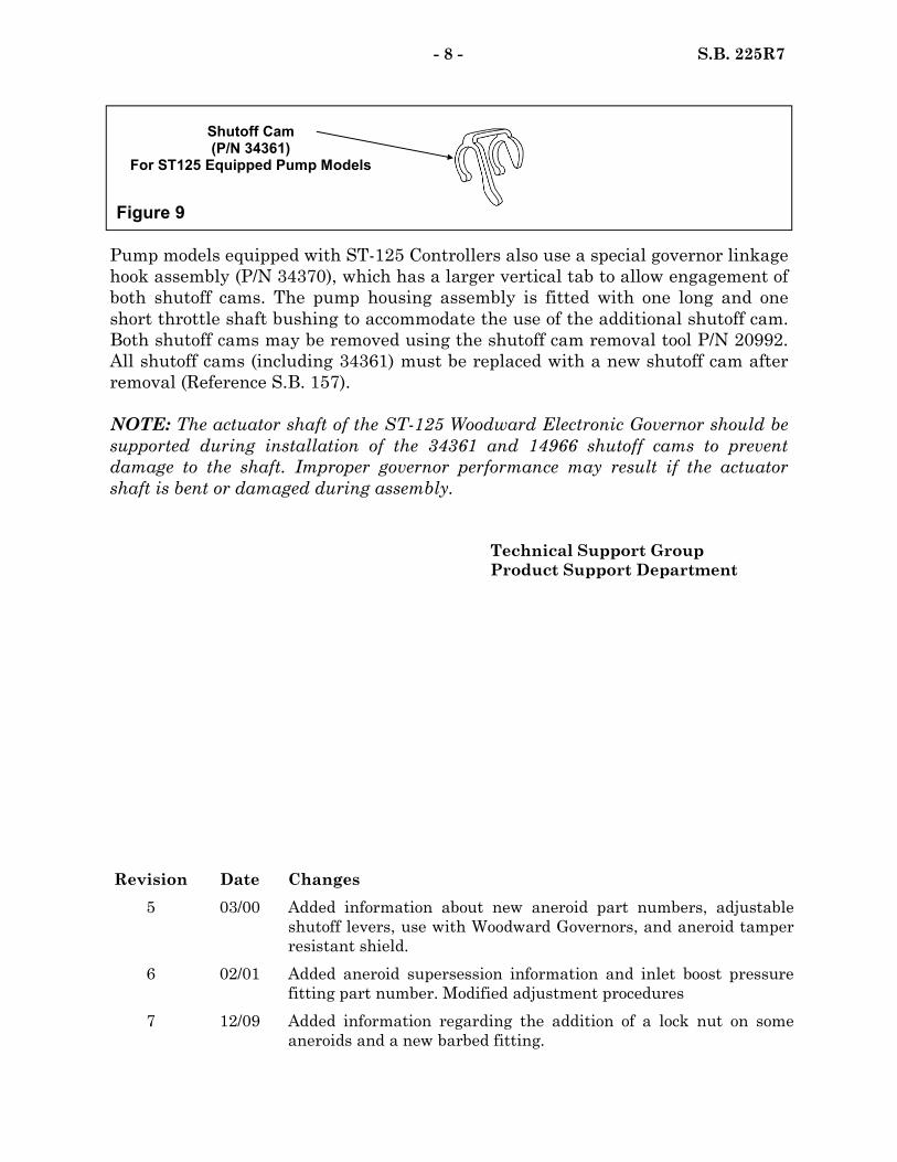
Figure 9
Shutoff Cam (P/N 34361)
For ST125 Equipped Pump Models
Pump models equipped with ST-125 Controllers also use a special governor linkage
hook assembly (P/N 34370), which has a larger vertical tab to allow engagement of
both shutoff cams. The pump housing assembly is fitted with one long and one
short throttle shaft bushing to accommodate the use of the additional shutoff cam.
Both shutoff cams may be removed using the shutoff cam removal tool P/N 20992.
All shutoff cams (including 34361) must be replaced with a new shutoff cam after
removal (Reference S.B. 157).
NOTE: The actuator shaft of the ST-125 Woodward Electronic Governor should be
supported during installation of the 34361 and 14966 shutoff cams to prevent
damage to the shaft. Improper governor performance may result if the actuator
shaft is bent or damaged during assembly.
Technical Support Group
Product Support Department
- 8 - S.B. 225R7
Revision Date Changes
5 03/00 Added information about new aneroid part numbers, adjustable
shutoff levers, use with Woodward Governors, and aneroid tamper
resistant shield.
6 02/01 Added aneroid supersession information and inlet boost pressure
fitting part number. Modified adjustment procedures
7 12/09 Added information regarding the addition of a lock nut on some
aneroids and a new barbed fitting.

Transfer Pump Blade and Liner Materials Stanadyne D series mechanical fuel pumps employ two types of transfer pump blades and liners depending on the type of fuel the pump is going to be operated with. For applications designed to be operated on traditional diesel fuel, standard blades and liners have been found to provide very satisfactory service life (Ref. Figure 1a for standard blade identification). When the OEM customer anticipates that the application will be operated on reduced viscosity fuels such as Jet-A or JP8 or with reduced lubricity diesel fuels, they can specify blades and liners made of tougher materials to achieve a satisfactory service life (Ref. Figure 1b for identification). To determine the correct transfer pump components to use in a given fuel pump, always refer to the individual specification. Note: On occasions, a pump that does not specify low viscosity transfer pump components may have been modified by customer request to include LVFC. In such cases, the pumps nameplate is stamped “LVFC” to identify this modification. Reference S.B. 125 for additional information on field conversions for low viscosity fuel operation.
A change in the material used to produce the low viscosity fuel use blades and liners took place in June 2005. The new low viscosity transfer pump components are made from a new material which offers the same resistance to wear as the previous M2 tool steel parts but only if the blades and liner are all made from the same material. In
Figure 1a
Previous
Drill Point Undercut Detail
Groove
Traditional Diesel Fuel Use
DATE: July 18, 2005 Supersedes: S.B. 304R8 dated
SERVICE BULLETIN
NO: 304R9
SUBJECT: TRANSFER PUMP BLADES AND LINERS FOR D SERIES MECHANICAL FUEL INJECTION PUMPS
Figure 1b
Stanadyne Corporation 92 Deerfield Road, Windsor, CT 06095, U.S.A. Tel: (860) 525-0821; Fax: (860) 683-4581; www.stanadyne.com
Low Viscosity Fuel Use
Drill
M2 Current
Chamfered Edges
Undercut Detail
Sharp Edges
Sintered Material

other words no mixing of the different material blade and liner types is permissible. Whenever transfer pump blade or liner replacements are performed, be sure that all components are of the same type of material. Failure to do so will result in the premature wear of one or more of the components. With the introduction of the new sintered transfer pump blades and liners for low viscosity fuel applications, the previous M-2 components will become obsolete and will be superseded by the corresponding sintered material component as stocks are depleted. Identification of the two types of low viscosity blades is shown in Figure 1b and liners are shown in Figure 2. Transfer Pump Liners Both traditional fuel use and low viscosity fuel use transfer pump liners for D series mechanical pumps are pictured below in Figure 2. Again, be sure to use the liner specified and always use blades made of the corresponding material in order to obtain the proper service life.
Transfer Pump Liner Identification
Standard and Oversize Blades A number of rotors have oversized blade slots (.001 inch [.254 mm] wider than normal), making it necessary to offer oversize blades. Part numbers in parentheses in Figure 3 are the oversize versions of each blade type. Oversized blades, part numbers 20512, 20804 and 37449, are blackened for identification. To determine if an oversize blade should be used in a particular rotor slot, try fitting an oversized blade into each of the four rotor slots. If the oversized blade fits freely into any of the slots, oversize blades should be used in these slots. Standard size blades must be used in any slots that will not accept oversize blades. It is permissible to use any combination of standard and oversize blades in the same rotor.
Traditional Fuel Application Low Viscosity Fuel Application
M-2 Current Material
16753 18658 37452
21232 22988 37447
Notched Dimpled
Dimpled
Drill Point
Drill Point
Etched P/N
Etched P/N
Etched P/N
None
Figure 2
- 2 - S.B. 304R9

- 3 - S.B. 304R9
Figure 3
+.0015 Slot size “A” +.001
Slot Size “B” +.0005 Slot Size “C” Standard
Slot Size “D”
Traditional Diesel Fuel 34758 20512 34759 20511(20512)
Low Viscosity Fuel M2 33499 20804 33501 20803 (20804)
Fitted Blades for Low Speed Fuel Limiter (LSFL) Equipped Pumps The fit of the transfer pump blades in the rotor slots of pumps equipped with Low Speed Fuel Limiter is critical. To ensure proper operation of the LSFL, two more blade thicknesses in addition to the standard and oversize versions are use in pumps equipped with the LSFL feature. The additional blade sizes are also available for both traditional diesel fuel and for low viscosity fuel use. The four fitted blade sizes and identification markings are shown in Figure 3.
Low Viscosity Fuel Sintered Material
37265 37267 37268 37266 (37449*)
*NOTE: Blade P/N 37266 is used for production purposes and is the same dimensionally as P/N 37449 except it has a groove for identification in-stead of being blackened. Therefore, P/N 37266 is superseded for service by P/N 37449.
The choice of four sizes provides greater control of the blade to slot clearance. In production, the blade slots are measured and the rotors are marked (Reference Figure 4) with the appropriate letter size (A, B, C, or D) to ensure the best fit blade is used.
Letter Marking on Rotor to Indicate Blade Slot Size
Figure 4

Revision Date Description 8 1/03 Added identification change and P/N’s 34758 and 34759
9 7/05 Added introduction of sintered blades and liners
In service, replacement blades should be selected in the same manner. Example: if the rotor is marked with the letter “C” with a 21232 transfer pump liner, then four P/N 34759 blades should be installed.
NOTE: Some production pumps were built with a blade one size smaller than the letter marking on the rotor, due to blade binding during assembly. If this situation is encountered and blade replacement is needed, use the same size blades that were originally installed. Always check blade fit during assembly to ensure the correct blade goes in the corresponding rotor slot.
Please be reminded that only rotors in pumps equipped with low speed fuel limiters will have letter markings on the rotor and require the use of the additional two blade sizes. Pumps without fuel limiters should continue to use the appropriate standard and/or oversize (+.001”) blades only.
Technical Support Group Product Support Department
- 4 - S.B. 304R9


NO: 338Rl
SERVICE BUL DATE: February 26.1990 SUPERSEDES: SJ3.338 dated 6/16/78
SUBJEcT: OVERSIZE CAMRINGS
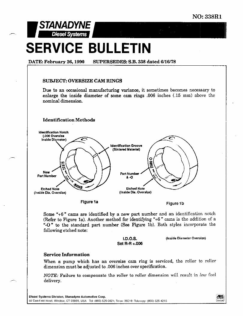
Due to an occasional manufactnring variance, it sometimes becomes necessary to enlarge the inside diameter of some cam rings .006 inches t.15 mm) above the nominal dimension.
Identification Methods
identification Notch
ldentifkation Groove (Sintered Material)
Part Number 6-O
Etched Note (Inslde Dia. Oversize)
Etched Note (Inside Dia. Oversize)
Figure la Figure 1 b
Some “+6 n cams are identified by a new part number and an identification notch (Refer to Figure la). Another method for identifying “+6 n cams is the addition of a "-0 n to the standard part number (See Figure lb). Both styles incorporate the following etched note:
I.D.O.S. Set R-R +.006
(Inside Diameter Oversize)
Service Information
When a pump which has an oversize cam ring is serviced, the roller to roller dimension must be adjusted to .006 inches over specification.
NOTE: Failure to compensate the roller to roller dimension will result in Low fuel delivery.

-2- S.B. 338Rl
Replacement Information
Oversize cam rings are used in production but are not sold as serviceable items. If it
is necessary to replace a “+6 n cam, refer to the following chart for the correct
standard size cam ring part number. Also, reference S.B. 99 (S.B. 332 for DM 4 plunger pumps) to determine if the leaf spring (or shoes for DM pumps) must be changed in order to obtain the correct roller to roller setting. _
NOTE: When a standard size cam ring is used to replace an oversize one, the roller to roller setting must be set back to the original specification. Failure to do so will result in high fuel delivery.
Over&e Cam Ring Replacement Information
Type Original Original
Std. Size P/N O/S +.006” P/N Replacement Std. Size P/N
Automotive
Aghdustrial
21116 22075 22339 22625 22392 22626 23057 23065 23119 23120 23824 23825 21357 22137 21371 22139 21686 21686-O 21687 21687-O
21116or26000 22339or27835
26000 23065or26001
27833 23824or27834
21687 la784 21686 21687
Technical Support Group Product Support Department

DATE: February 19, 1999 SUPERSEDES: S.B. 373R1 dated 6/25/97
SERVICE BULLETIN
NO: 373R2
Diesel Systems Division, Stanadyne Automotive Corp. 92 Deerfield Road, Windsor, CT 06095, U.S.A. Tel: (860) 525-0821; Fax: (860) 683-4581
SUBJECT: SERVO SPEED LIGHT LOAD ADVANCE
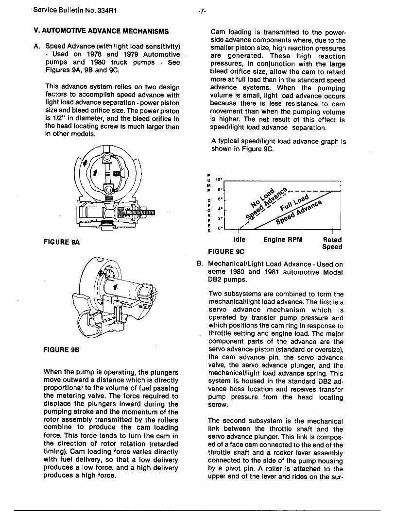
As legislation continues to mandate decreases in diesel engine emissions, engine manufacturers find it necessary to more closely control fuel delivery and injection timing functions. Stanadyne plays a significant roll in this effort by developing special injection pump features such as the Servo Speed Light Load Advance. This feature is designed to optimize injection timing under part load and no load conditions in order to minimize exhaust emissions and smoke levels. This service bulletin outlines the various types of Servo Speed Light Load Advances that are used on Stanadyne D Series pumps. Servo Speed Light Load Advance Principles of Operation The Servo Speed Light Load Advance (SSLLA) feature has been utilized in Stanadyne D Series pumps for over 15 years but has recently undergone several redesigns to make it more manufacturable, settable, and serviceable. Figure 1 shows a schematic view of a typical SSLLA.
Figure 1
Charging Pressure
Housing Pressure
Inlet Pressure
Transfer Pressure
-2- S.B. 373R2
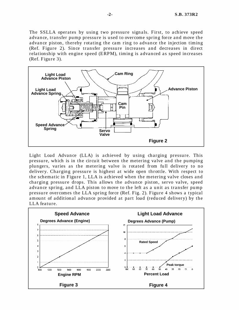
The SSLLA operates by using two pressure signals. First, to achieve speed advance, transfer pump pressure is used to overcome spring force and move the advance piston, thereby rotating the cam ring to advance the injection timing (Ref. Figure 2). Since transfer pressure increases and decreases in direct relationship with engine speed (ERPM), timing is advanced as speed increases (Ref. Figure 3).
Light Load Advance (LLA) is achieved by using charging pressure. This pressure, which is in the circuit between the metering valve and the pumping plungers, varies as the metering valve is rotated from full delivery to no delivery. Charging pressure is highest at wide open throttle. With respect to the schematic in Figure 1, LLA is achieved when the metering valve closes and charging pressure drops. This allows the advance piston, servo valve, speed advance spring, and LLA piston to move to the left as a unit as transfer pump pressure overcomes the LLA spring force (Ref. Fig. 2). Figure 4 shows a typical amount of additional advance provided at part load (reduced delivery) by the LLA feature.
Speed Advance Spring
Light Load Advance Spring
Light Load Advance Piston
Cam Ring
Cam Pin
Servo Valve
Advance Piston
Figure 2
Speed Advance Light Load Advance Degrees Advance (Pump) Degrees Advance (Engine)
Engine RPM Percent Load
Figure 3 Figure 4
Rated Speed
Peak torque
-3- S.B. 373R2
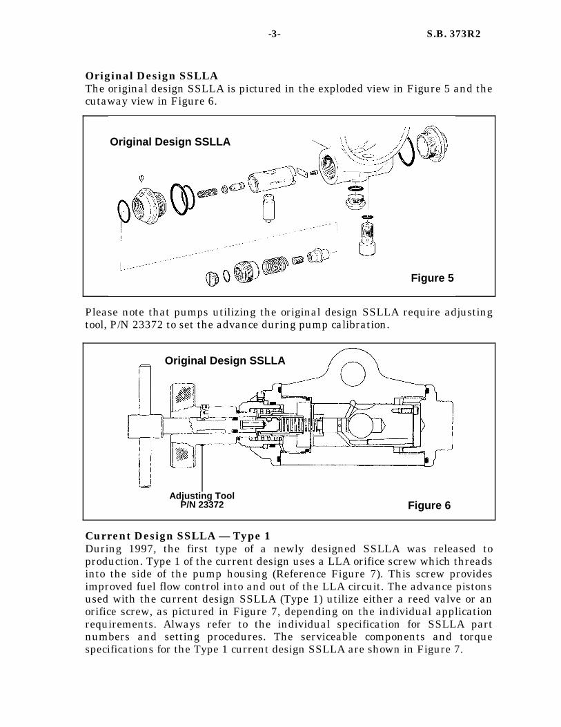
Original Design SSLLA The original design SSLLA is pictured in the exploded view in Figure 5 and the cutaway view in Figure 6.
Please note that pumps utilizing the original design SSLLA require adjusting tool, P/N 23372 to set the advance during pump calibration.
Current Design SSLLA — Type 1 During 1997, the first type of a newly designed SSLLA was released to production. Type 1 of the current design uses a LLA orifice screw which threads into the side of the pump housing (Reference Figure 7). This screw provides improved fuel flow control into and out of the LLA circuit. The advance pistons used with the current design SSLLA (Type 1) utilize either a reed valve or an orifice screw, as pictured in Figure 7, depending on the individual application requirements. Always refer to the individual specification for SSLLA part numbers and setting procedures. The serviceable components and torque specifications for the Type 1 current design SSLLA are shown in Figure 7.
Original Design SSLLA
Figure 5
Figure 6
Original Design SSLLA
Adjusting Tool P/N 23372

NOTE: Some applications also use a Teflon® washer to properly position the seal between the advance plug(s) and the pump housing. Refer to the individual pump specification to determine if a Teflon® washer is used. Teflon washers are to be replaced during pump service and should not be reused. The Type 1 current design SSLLA uses a nylon patch on the threads of both the light load and speed advance adjusting screws for retention purposes. The speed advance adjusting screw threads into the LLA piston and the LLA adjusting screw is threaded into the LLA advance plug. Service Tool 33196 is required for making advance adjustments during pump calibration as shown in Figure 8.
Figure 8 Adjusting Tool P/N 33196*
*Tool is used as pictured for speed advance adjustment and inverted end for end to make load advance adjustment
1/8” (3.17mm) Hex Driver P/N 16336
Advance Adjustments on Type 1 of the Current Design SSLLA
Current Design SSLLA — Type 1
-4- S.B. 373R2
Orifice Screw 6-8 lbf.-inches (0.68-0.90 N•m)
O-ring P/N 32883
Reed Valve Screw 3-5 lbf.-inches (0.35-0.55 N•m)
Teflon® Washer
(See Note)
Advance End Plugs 455-505 lbf.-inches
(51.4-57.0 N•m)
Advance Cap 215-265 lbf.-inches
(24.3-29.9 N•m)
LLA Adjusting Screw
Speed Advance Adjusting Screw
P/N 32479
Figure 7
LLA Orifice Screw, P/N 32513 140-160 lbf.-inches
(15.8-18.1 N•m)

Viscosity Sensitive Advance Feature Stanadyne introduced a modified version of the current SSLLA referred to as a viscosity sensitive advance. It is designed to reduce sensitivity to fuel viscosity changes in the LLA circuit, and consists of a different LLA orifice screw and speed advance adjusting screw. Only a small number of applications require the viscosity sensitive advance and at this time there are approximately 15 pump specifications that have this feature. The LLA orifice screw contains a flatted pin instead of an orifice to control the flow of metered fuel to the LLA piston cavity. There are three LLA orifice screw assemblies with different sized flatted pins for the viscosity sensitive advance. Part numbers are located on the head of the screw for identification purposes. The speed advance adjusting screw has an orifice located in the center of the screw. At this time there are currently two adjusting screws with different size orifices for these applications. Cutaway views of the standard (non-viscosity sensitive) and the viscosity sensitive LLA features are shown below in Figures 9a and 9b.
Current Design SSLLA — Type 2 Stanadyne has introduced a variation of the current design SSLLA to address adjustability and retention issues with the speed and LLA adjusting screws. The Type 2 or “patchless” design includes a press fit speed advance adjustment plug and a light load advance adjusting screw that uses an o-ring for retention purposes. These changes allowed for the removal of the nylon patch on the speed advance and LLA adjusting screws which contributed to the adjustability and retention issues. Other changes include a redesigned LLA orifice screw
-5- S.B. 373R2
Standard SSLLA Design Viscosity Sensitive SSLLA
Speed Advance Adjusting Screw,
P/N 32479
Figure 9a
Speed Advance Adjusting Screw with Orifice,
P/N’s 33941 and 33982
Figure 9b
LLA Orifice Screw, External Hex with Flatted Pin, P/N’s 33942, 33981, and 33988
140-160 lbf.-inches (15.8-18.1 N•m)
LLA Orifice Screw, Button Head with Orifice, P/N 32513
140-160 lbf.-inches (15.8-18.1 N•m)

(Figure 9), a new LLA plug (Figure 10) and the inclusion of a filter that is incorporated in the hydraulic head (Figure 13) to prevent debris from entering the LLA orifice screw. Torque values are the same for both Type 1 and Type 2 of the current design SSLLA and are shown in Figure 7. An exploded view highlighting the unique components of the Type 2 design is shown in Figure 10.
All pump models originally released with the Type 1 SSLLA have been or are being changed to incorporate the components of the Type 2 design. Servicing Current Type 1 and Type 2 SSLLA’s When a pump is received for service with the Type 1 SSLLA, it does not have to be upgraded to the patchless (Type 2) advance components. However the previously used speed advance adjusting screws, light load advance pistons and light load advance adjusting screws have been superseded and will no longer be available for service. Therefore, if any of these components do require replacement during service, they will have to upgraded with the appropriate Type 2 advance component(s).
-6- S.B. 373R2
Type 2 (Patchless Advance) of the Current Design SSLLA
External Hex Head LLA Orifice Screw,
P/N 33985 O-ring, P/N 17438
O-ring Retained LLA Adjusting
Screw, P/N 33614
O-ring, P/N 33613
Speed Advance Adjusting Plug, P/N 33905
LLA Piston for Press Fit Adjusting Plug (various P/N’s)
LLA End Plug with
Relief
Figure 10
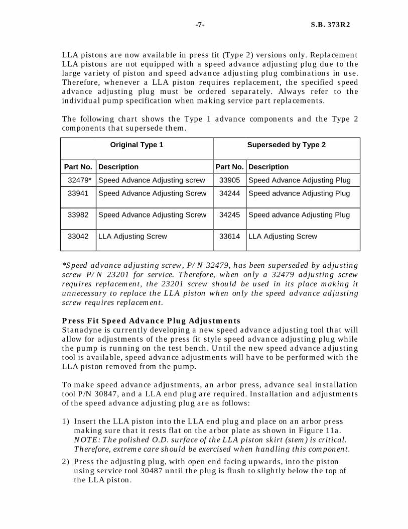
LLA pistons are now available in press fit (Type 2) versions only. Replacement LLA pistons are not equipped with a speed advance adjusting plug due to the large variety of piston and speed advance adjusting plug combinations in use. Therefore, whenever a LLA piston requires replacement, the specified speed advance adjusting plug must be ordered separately. Always refer to the individual pump specification when making service part replacements. The following chart shows the Type 1 advance components and the Type 2 components that supersede them.
*Speed advance adjusting screw, P/N 32479, has been superseded by adjusting screw P/N 23201 for service. Therefore, when only a 32479 adjusting screw requires replacement, the 23201 screw should be used in its place making it unnecessary to replace the LLA piston when only the speed advance adjusting screw requires replacement. Press Fit Speed Advance Plug Adjustments Stanadyne is currently developing a new speed advance adjusting tool that will allow for adjustments of the press fit style speed advance adjusting plug while the pump is running on the test bench. Until the new speed advance adjusting tool is available, speed advance adjustments will have to be performed with the LLA piston removed from the pump. To make speed advance adjustments, an arbor press, advance seal installation tool P/N 30847, and a LLA end plug are required. Installation and adjustments of the speed advance adjusting plug are as follows: 1) Insert the LLA piston into the LLA end plug and place on an arbor press
making sure that it rests flat on the arbor plate as shown in Figure 11a. NOTE: The polished O.D. surface of the LLA piston skirt (stem) is critical. Therefore, extreme care should be exercised when handling this component.
2) Press the adjusting plug, with open end facing upwards, into the piston using service tool 30487 until the plug is flush to slightly below the top of the LLA piston.
Original Type 1
Part No. Description Part No. Description
32479* Speed Advance Adjusting screw 33905 Speed Advance Adjusting Plug
33941 Speed Advance Adjusting Screw 34244 Speed advance Adjusting Plug
33982 Speed Advance Adjusting Screw 34245 Speed advance Adjusting Plug
33042 LLA Adjusting Screw 33614 LLA Adjusting Screw
Superseded by Type 2
-7- S.B. 373R2
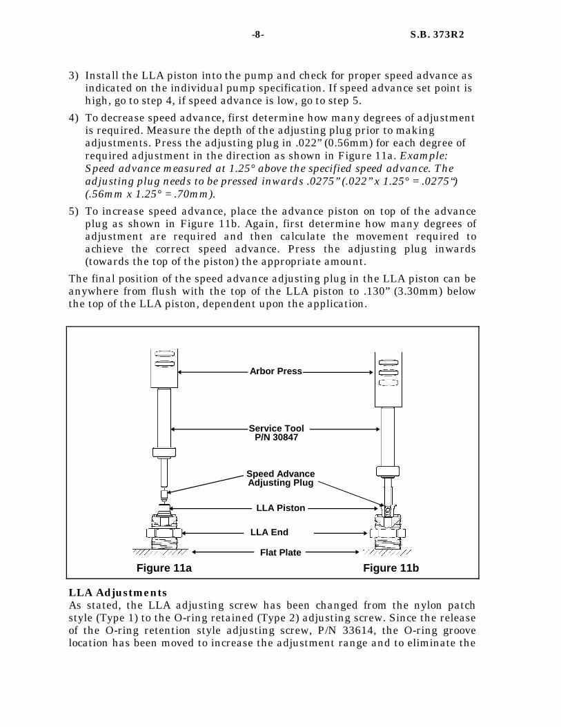
3) Install the LLA piston into the pump and check for proper speed advance as indicated on the individual pump specification. If speed advance set point is high, go to step 4, if speed advance is low, go to step 5.
4) To decrease speed advance, first determine how many degrees of adjustment is required. Measure the depth of the adjusting plug prior to making adjustments. Press the adjusting plug in .022” (0.56mm) for each degree of required adjustment in the direction as shown in Figure 11a. Example: Speed advance measured at 1.25° above the specified speed advance. The adjusting plug needs to be pressed inwards .0275” (.022” x 1.25° = .0275“) (.56mm x 1.25° = .70mm).
5) To increase speed advance, place the advance piston on top of the advance plug as shown in Figure 11b. Again, first determine how many degrees of adjustment are required and then calculate the movement required to achieve the correct speed advance. Press the adjusting plug inwards (towards the top of the piston) the appropriate amount.
The final position of the speed advance adjusting plug in the LLA piston can be anywhere from flush with the top of the LLA piston to .130” (3.30mm) below the top of the LLA piston, dependent upon the application.
LLA Adjustments As stated, the LLA adjusting screw has been changed from the nylon patch style (Type 1) to the O-ring retained (Type 2) adjusting screw. Since the release of the O-ring retention style adjusting screw, P/N 33614, the O-ring groove location has been moved to increase the adjustment range and to eliminate the
-8- S.B. 373R2
Figure 11a Figure 11b Flat Plate
LLA End
LLA Piston
Speed Advance Adjusting Plug
Service Tool P/N 30847
Arbor Press
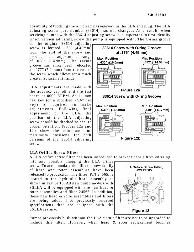
possibility of blocking the air bleed passageway in the LLA end plug. The LLA adjusting screw part number (33614) has not changed. As a result, when servicing pumps with the 33614 adjusting screw it is important to first identify which version adjusting screw the pump is equipped with. The O-ring groove on the original 33614 adjusting screw is located .175” (4.45mm) from the end of the screw and provides an adjustment range of .058” (1.47mm). The O-ring groove has since been relocated at .277” (7.04mm) from the end of the screw which allows for a much greater adjustment range. LLA adjustments are made with the advance cap off and the test bench at 0000 ERPM. An 11 mm hex key (or a modified 7/16” hex key) is required to make adjustments. Following final adjustment of the LLA, the position of the LLA adjusting screw should be checked to ensure proper retention. Figures 12a and 12b show the minimum and maximum positions for both versions of the 33614 adjusting screw. LLA Orifice Screw Filter A LLA orifice screw filter has been introduced to prevent debris from entering into and possibly plugging the LLA orifice screw. To accommodate this filter, a new family of head and rotor assemblies have been released to production. The filter, P/N 24565, is located in the hydraulic head assembly as shown in Figure 13. All new pump models with SSLLA will be equipped with the new head & rotor assemblies and filter 24565. In addition, these new head & rotor assemblies and filters are being added into previously released specifications that are equipped with the SSLLA feature. Pumps previously built without the LLA circuit filter are not to be upgraded to include this filter. However, when head & rotor replacement becomes
-9- S.B. 373R2
LLA Orifice Screw Filter, P/N 24565
Figure 13
33614 Screw with O-ring Groove
.630” (16.0mm) Max. Position Min. Position
.440” (11.17mm)
Figure 12b
Min. Position
33614 Screw with O-ring Groove at .175” (4.45mm)
.630” (16.0mm) Max. Position
.572” (14.53mm)
Figure 12a

necessary, the current head & rotor assemblies, which are packaged with the 24565 filter, are to be used. In order to properly seal metered fuel pressure and to seat the orifice screw filter in the hydraulic head assembly, it was necessary to release new LLA orifice screws. As a result, whenever a head & rotor is being replaced in a pump that did not originally contain a 24565 filter, the appropriate LLA orifice screw and associated seals will also have to be installed. The original and new LLA orifice screws designs are shown below in Figure 14.
There are currently four versions of the LLA orifice screw. One uses an orifice to control the metered fuel pressure signal to the LLA advance while the other three use a flatted pin. The LLA orifice screws with flatted pins are visually similar, but are differentiated by their flow rates. Part numbers are located on the hex head portion of the screw for identification. For service, the new LLA orifice screws can be used on pumps without the 24565 filter. However, the old style orifice screws are not to be used with head & rotor assemblies that contain the 24565 filter. The following chart shows the original and the superseding LLA orifice screws part numbers. Again, always refer to the individual pump specification when making service part replacements.
LLA Orifice Screws Used in Pumps without Filter 24565
Part No. Description (flow rate) Part No. Description (flow rate)
32513 Orifice Type, Button Head 33985 Orifice Type, External Hex Head
33988 Flatted Pin Type (125 ml/min) 34176 Flatted Pin Type (125 ml/min)
33981 Flatted Pin Type (150 ml/min) 34174 Flatted Pin Type (150 ml/min)
33942 Flatted Pin Type (250 ml/min) 34175 Flatted Pin Type (250 ml/min)
LLA Orifice Screws Used in Pumps with Filter 24565
-10- S.B. 373R2
Redesigned Sealing area Used in SSLLA pumps without the
24565 Filter Used in all SSLLA pumps
P/N 32513, Button Head Style with
orifice
P/N 33985, Hex Head style
with orifice
Figure 14
P/N’s 33998, 33981, and 33942, Hex head style with flatted pin
P/N’s 34176, 34174, 34175, Hex head
style with flatted pin

Technical Support Group Product Support Department
-11- S.B. 373R2
Revision Date Changes
1 6/97 Added new SSLLA and CSA information 2 12/98 Added Type 2 SSLLA information. Information
regarding Cold Start Advance Mechanisms was removed and added to S.B. 373AR2.


Stanadyne developed the cold start advance (CSA) feature to assist engine manufacturers in reducing the white exhaust smoke associated with cold temperature starting and operation of diesel engines. The white exhaust smoke is caused by unburned fuel due to an incomplete combustion process. By advancing the fuel injection timing during cold engine operation, combustion efficiency is improved and white exhaust smoke is minimized. Once the engine coolant temperature is sufficiently elevated, the injection timing and advance functionality are returned to normal operation. Stanadyne’s cold start advance mechanisms are used on servo-speed light load advance (SSLLA, Ref. S.B. 373) equipped DB2 (non-automotive) and DB4 pump models and may either be operated electronically (solenoid actuated) or manually (mechanically actuated). Solenoid Actuated Cold Start Advance The automatic operation of the solenoid actuated cold start advance provides precise cold engine injection timing control. There are several variations of solenoid hardware and operating parameters but the general operation of the solenoid actuated CSA design is consistent. A typical solenoid actuated CSA mechanism is shown in Figure 1.
Stanadyne Corporation 92 Deerfield Road, Windsor, CT 06095, U.S.A. Tel: (860) 525-0821; Fax: (860) 683-4581; www.stanadyne.com
NO: 373AR5 DATE: February 2, 2011
SUPERSEDES: S.B. 373AR4 dated JUNE 18, 2009
SERVICE BULLETIN
SUBJECT: COLD START ADVANCE FEATURE
CSA Piston
Figure 1
Transfer Pump Pressure Feed to CSA Solenoid
Servo Advance Piston
Head Locating Screw
CSA End Plug Assembly
Cam Pin
CSA Solenoid Assembly
Metered Fuel Pressure Pump Housing Pressure Transfer Pump Pressure
Coil
Valve Body
Spring
Spring
Plunger
Check Ball
Lock Nut
CSA Piston Retaining Ring
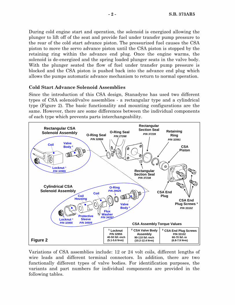
During cold engine start and operation, the solenoid is energized allowing the plunger to lift off of the seat and provide fuel under transfer pump pressure to the rear of the cold start advance piston. The pressurized fuel causes the CSA piston to move the servo advance piston until the CSA piston is stopped by the retaining ring within the advance end plug. Once the engine warms, the solenoid is de-energized and the spring loaded plunger seats in the valve body. With the plunger seated the flow of fuel under transfer pump pressure is blocked and the CSA piston is pushed back into the advance end plug which allows the pumps automatic advance mechanism to return to normal operation. Cold Start Advance Solenoid Assemblies Since the introduction of this CSA design, Stanadyne has used two different types of CSA solenoid/valve assemblies - a rectangular type and a cylindrical type (Figure 2). The basic functionality and mounting configurations are the same. However, there are some differences between the individual components of each type which prevents parts interchangeability.
- 2 - S.B. 373AR5
Variations of CSA assemblies include: 12 or 24 volt coils, different lengths of wire leads and different terminal connectors. In addition, there are two functionally different types of valve bodies. For identification purposes, the variants and part numbers for individual components are provided in the following tables.
Figure 2
Cylindrical CSA Solenoid Assembly
Protective Sleeve
P/N 34505
Coil Housing
Coil
Flux Washer
P/N 34267
Valve Body ²
O-Ring P/N 29525
Locknut ¹ P/N 32955 CSA Assembly Torque Values
Rectangular Section Seal
P/N 37238
Rectangular CSA Solenoid Assembly
Locknut ¹ P/N 32955
Coil Valve Body ²
O-Ring Seal P/N 32866
CSA Piston
Retaining Ring
P/N 32561
CSA End Plug
O-Ring Seal P/N 27268
Rectangular Section Seal
P/N 37239
CSA End Plug Screws ³
P/N 33102
¹ Locknut P/N 32955
40-50 lbf.-inch (5.1-5.6 N•m)
² CSA Valve Body Assembly
90-110 lbf.-inch (10.2-12.4 N•m)
³ CSA End Plug Screws P/N 33102
60-70 lbf.-in (6.8-7.9 N•m)
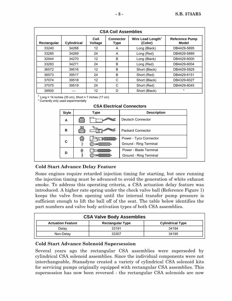
Cold Start Advance Delay Feature Some engines require retarded injection timing for starting, but once running the injection timing must be advanced to avoid the generation of white exhaust smoke. To address this operating criteria, a CSA actuation delay feature was introduced. A higher rate spring under the check valve ball (Reference Figure 1) keeps the valve from opening until the internal transfer pump pressure is sufficient enough to lift the ball off of the seat. The table below identifies the part numbers and valve body activation types of both CSA assemblies.
- 3 - S.B. 373AR5
Cold Start Advance Solenoid Supersession Several years ago the rectangular CSA assemblies were superseded by cylindrical CSA solenoid assemblies. Since the individual components were not interchangeable, Stanadyne created a variety of cylindrical CSA solenoid kits for servicing pumps originally equipped with rectangular CSA assemblies. This supersession has now been reversed - the rectangular CSA solenoids are now
Rectangular Cylindrical Coil
Voltage Connector
Type Wire Lead Length†
(Color) Reference Pump
Model 33240 34268 12 A Long (Black) DB4429-5895 33285 34269 24 A Long (Red) DB4629-5889 32944 34270 12 B Long (Black) DB4429-6000 33283 34271 24 B Long (Red) DB4429-6004 36572 39516 12 B Short (Black) DB4429-5929 36573 39517 24 B Short (Red) DB4429-6151 37074 39518 12 C Short (Black) DB4329-6027 37075 39519 24 C Short (Red) DB4429-6045 39500 — 12 D Short (Black) *
CSA Coil Assemblies
CSA Valve Body Assemblies Actuation Feature Rectangular Type Cylindrical Type
Delay 33191 34194 Non-Delay 33307 34195
† Long ≈ 14 inches (35 cm), Short ≈ 7 inches (17 cm) * Currently only used experimentally
CSA Electrical Connectors
A
B
Style Description
C
D
Type
Deutsch Connector
Packard Connector
Power - Tyco Connector Ground - Ring Terminal
Power - Blade Terminal Ground - Ring Terminal
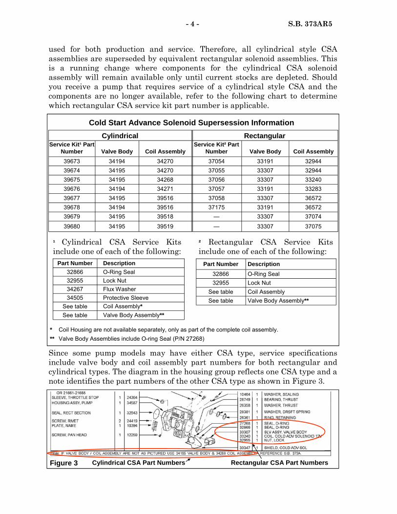
used for both production and service. Therefore, all cylindrical style CSA assemblies are superseded by equivalent rectangular solenoid assemblies. This is a running change where components for the cylindrical CSA solenoid assembly will remain available only until current stocks are depleted. Should you receive a pump that requires service of a cylindrical style CSA and the components are no longer available, refer to the following chart to determine which rectangular CSA service kit part number is applicable.
Since some pump models may have either CSA type, service specifications include valve body and coil assembly part numbers for both rectangular and cylindrical types. The diagram in the housing group reflects one CSA type and a note identifies the part numbers of the other CSA type as shown in Figure 3.
- 4 - S.B. 373AR5
Cylindrical Rectangular Service Kit¹ Part
Number Valve Body Coil Assembly Service Kit² Part
Number Valve Body Coil Assembly 39673 34194 34270 37054 33191 32944 39674 34195 34270 37055 33307 32944 39675 34195 34268 37056 33307 33240 39676 34194 34271 37057 33191 33283 39677 34195 39516 37058 33307 36572 39678 34194 39516 37175 33191 36572 39679 34195 39518 — 33307 37074
39680 34195 39519 — 33307 37075
Cold Start Advance Solenoid Supersession Information
* Coil Housing are not available separately, only as part of the complete coil assembly. ** Valve Body Assemblies include O-ring Seal (P/N 27268)
² Rectangular CSA Service Kits include one of each of the following:
Part Number Description 32866 O-Ring Seal 32955 Lock Nut
See table Coil Assembly See table Valve Body Assembly**
Part Number Description 32866 O-Ring Seal 32955 Lock Nut
34505 Protective Sleeve See table Coil Assembly* See table Valve Body Assembly**
34267 Flux Washer
¹ Cylindrical CSA Service Kits include one of each of the following:
Figure 3 Rectangular CSA Part Numbers Cylindrical CSA Part Numbers
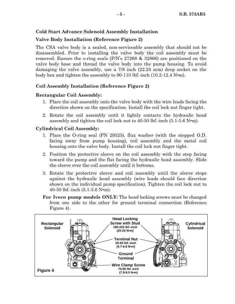
- 5 - S.B. 373AR5
Cold Start Advance Solenoid Assembly Installation Valve Body Installation (Reference Figure 2) The CSA valve body is a sealed, non-serviceable assembly that should not be disassembled. Prior to installing the valve body the coil assembly must be removed. Ensure the o-ring seals (P/N’s 27268 & 32866) are positioned on the valve body base and thread the valve body into the pump housing. To avoid damaging the valve assembly, use a 7/8 inch (22.25 mm) deep socket on the body hex and tighten the assembly to 90-110 lbf.-inch (10.2-12.4 N•m). Coil Assembly Installation (Reference Figure 2)
Rectangular Coil Assembly: 1. Place the coil assembly onto the valve body with the wire leads facing the
direction shown on the specification. Install the coil lock nut finger tight. 2. Rotate the coil assembly until it lightly contacts the hydraulic head
assembly and tighten the coil lock nut to 40-50 lbf.-inch (5.1-5.6 N•m). Cylindrical Coil Assembly: 1. Place the O-ring seal (PN 29525), flux washer (with the stepped O.D.
facing away from pump housing), coil assembly and the metal coil housing onto the valve body. Install the coil lock nut finger tight.
2. Position the protective sleeve on the coil assembly with the step facing toward the pump and the flat facing the hydraulic head assembly. Slide the sleeve over the coil assembly until it bottoms.
3. Rotate the protective sleeve and coil assembly until the sleeve stops against the hydraulic head assembly (wire leads should face direction shown on the individual pump specification). Tighten the coil lock nut to 40-50 lbf.-inch (5.1-5.6 N•m).
For Iveco pump models ONLY: The head locking screws must be changed from one side to the other for ground terminal connection (Reference Figure 4).
Ground Terminal
Wire Clamp Screw 70-80 lbf.-inch (7.9-9.0 N•m)
Cylindrical Solenoid
Rectangular Solenoid
Head Locking Screw with Stud
180-220 lbf.-inch (20-25 N•m)
Terminal Nut 50-60 lbf.-inch (5.7-6.8 N•m)
Figure 4
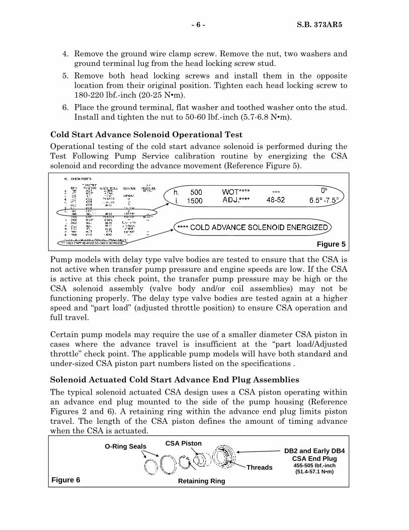
- 6 - S.B. 373AR5
4. Remove the ground wire clamp screw. Remove the nut, two washers and ground terminal lug from the head locking screw stud.
5. Remove both head locking screws and install them in the opposite location from their original position. Tighten each head locking screw to 180-220 lbf.-inch (20-25 N•m).
6. Place the ground terminal, flat washer and toothed washer onto the stud. Install and tighten the nut to 50-60 lbf.-inch (5.7-6.8 N•m).
Cold Start Advance Solenoid Operational Test Operational testing of the cold start advance solenoid is performed during the Test Following Pump Service calibration routine by energizing the CSA solenoid and recording the advance movement (Reference Figure 5).
Pump models with delay type valve bodies are tested to ensure that the CSA is not active when transfer pump pressure and engine speeds are low. If the CSA is active at this check point, the transfer pump pressure may be high or the CSA solenoid assembly (valve body and/or coil assemblies) may not be functioning properly. The delay type valve bodies are tested again at a higher speed and “part load” (adjusted throttle position) to ensure CSA operation and full travel.
Certain pump models may require the use of a smaller diameter CSA piston in cases where the advance travel is insufficient at the “part load/Adjusted throttle” check point. The applicable pump models will have both standard and under-sized CSA piston part numbers listed on the specifications .
Solenoid Actuated Cold Start Advance End Plug Assemblies The typical solenoid actuated CSA design uses a CSA piston operating within an advance end plug mounted to the side of the pump housing (Reference Figures 2 and 6). A retaining ring within the advance end plug limits piston travel. The length of the CSA piston defines the amount of timing advance when the CSA is actuated.
Figure 5
Figure 6
DB2 and Early DB4 CSA End Plug 455-505 lbf.-inch (51.4-57.1 N•m) Threads
Retaining Ring
CSA Piston O-Ring Seals
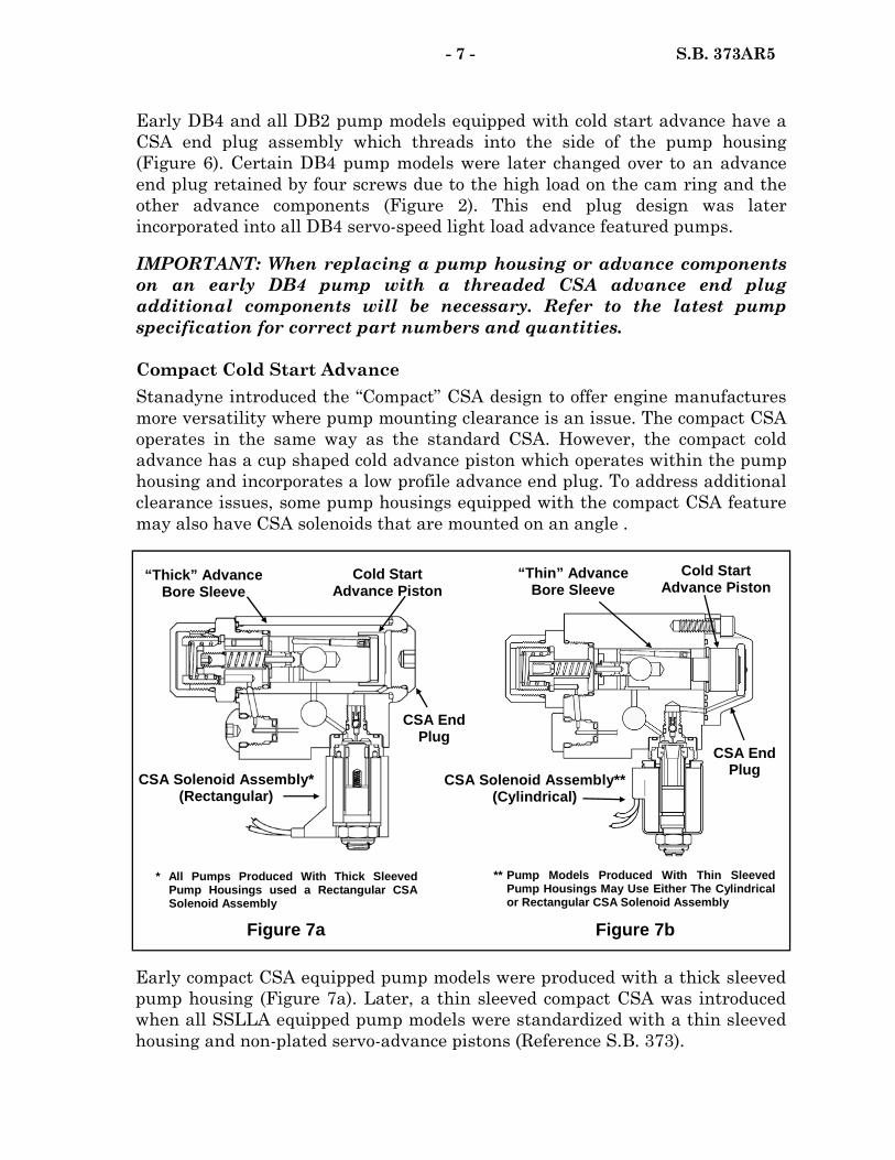
Early DB4 and all DB2 pump models equipped with cold start advance have a CSA end plug assembly which threads into the side of the pump housing (Figure 6). Certain DB4 pump models were later changed over to an advance end plug retained by four screws due to the high load on the cam ring and the other advance components (Figure 2). This end plug design was later incorporated into all DB4 servo-speed light load advance featured pumps.
IMPORTANT: When replacing a pump housing or advance components on an early DB4 pump with a threaded CSA advance end plug additional components will be necessary. Refer to the latest pump specification for correct part numbers and quantities. Compact Cold Start Advance Stanadyne introduced the “Compact” CSA design to offer engine manufactures more versatility where pump mounting clearance is an issue. The compact CSA operates in the same way as the standard CSA. However, the compact cold advance has a cup shaped cold advance piston which operates within the pump housing and incorporates a low profile advance end plug. To address additional clearance issues, some pump housings equipped with the compact CSA feature may also have CSA solenoids that are mounted on an angle .
Early compact CSA equipped pump models were produced with a thick sleeved pump housing (Figure 7a). Later, a thin sleeved compact CSA was introduced when all SSLLA equipped pump models were standardized with a thin sleeved housing and non-plated servo-advance pistons (Reference S.B. 373).
- 7 - S.B. 373AR5
Figure 7a
* All Pumps Produced With Thick Sleeved Pump Housings used a Rectangular CSA Solenoid Assembly
“Thick” Advance Bore Sleeve
Cold Start Advance Piston
CSA Solenoid Assembly* (Rectangular)
CSA End Plug
Figure 7b
Cold Start Advance Piston
“Thin” Advance Bore Sleeve
** Pump Models Produced With Thin Sleeved Pump Housings May Use Either The Cylindrical or Rectangular CSA Solenoid Assembly
CSA End Plug
CSA Solenoid Assembly** (Cylindrical)
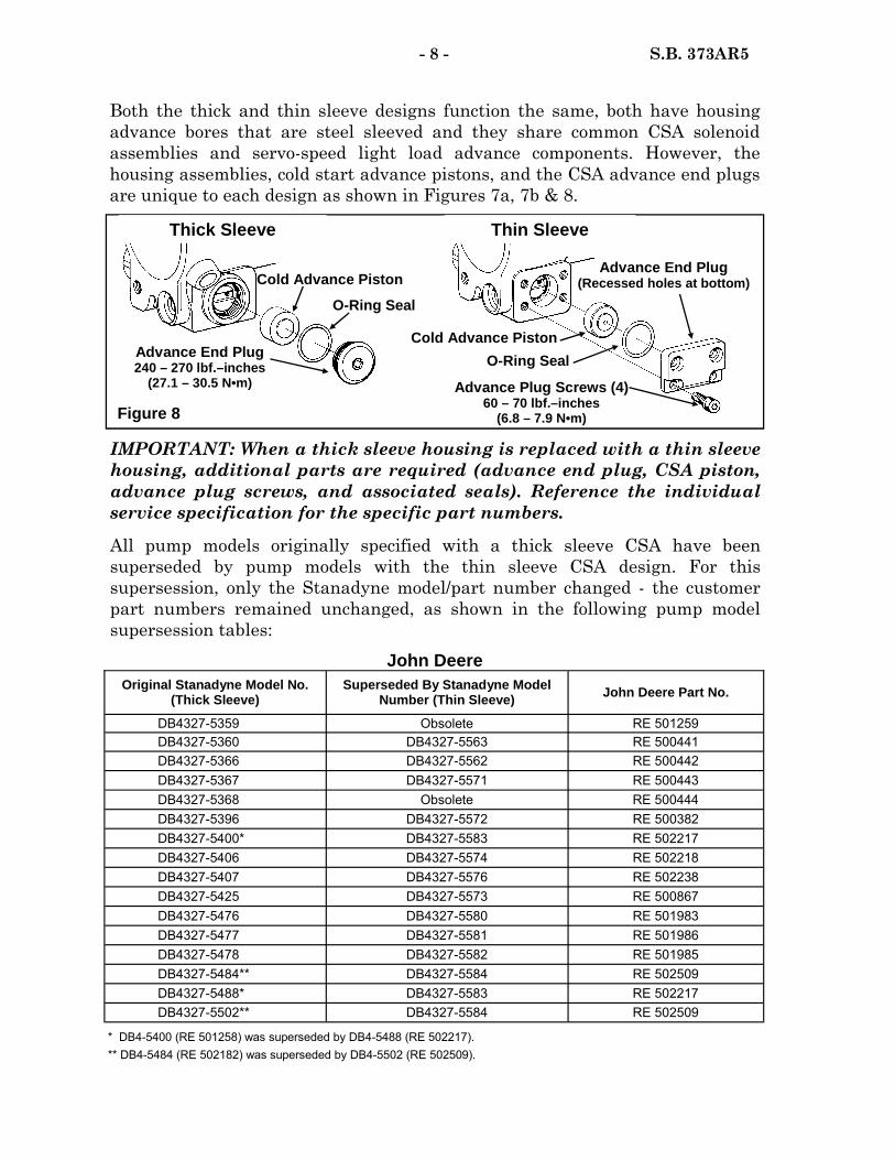
- 8 - S.B. 373AR5
Original Stanadyne Model No. (Thick Sleeve)
Superseded By Stanadyne Model Number (Thin Sleeve) John Deere Part No.
DB4327-5359 Obsolete RE 501259 DB4327-5360 DB4327-5563 RE 500441 DB4327-5366 DB4327-5562 RE 500442 DB4327-5367 DB4327-5571 RE 500443 DB4327-5368 Obsolete RE 500444 DB4327-5396 DB4327-5572 RE 500382 DB4327-5400* DB4327-5583 RE 502217 DB4327-5406 DB4327-5574 RE 502218 DB4327-5407 DB4327-5576 RE 502238 DB4327-5425 DB4327-5573 RE 500867 DB4327-5476 DB4327-5580 RE 501983 DB4327-5477 DB4327-5581 RE 501986 DB4327-5478 DB4327-5582 RE 501985 DB4327-5484** DB4327-5584 RE 502509 DB4327-5488* DB4327-5583 RE 502217 DB4327-5502** DB4327-5584 RE 502509
* DB4-5400 (RE 501258) was superseded by DB4-5488 (RE 502217). ** DB4-5484 (RE 502182) was superseded by DB4-5502 (RE 502509).
John Deere
IMPORTANT: When a thick sleeve housing is replaced with a thin sleeve housing, additional parts are required (advance end plug, CSA piston, advance plug screws, and associated seals). Reference the individual service specification for the specific part numbers.
All pump models originally specified with a thick sleeve CSA have been superseded by pump models with the thin sleeve CSA design. For this supersession, only the Stanadyne model/part number changed - the customer part numbers remained unchanged, as shown in the following pump model supersession tables:
Both the thick and thin sleeve designs function the same, both have housing advance bores that are steel sleeved and they share common CSA solenoid assemblies and servo-speed light load advance components. However, the housing assemblies, cold start advance pistons, and the CSA advance end plugs are unique to each design as shown in Figures 7a, 7b & 8.
Figure 8
O-Ring Seal
Advance End Plug 240 – 270 lbf.–inches
(27.1 – 30.5 N•m)
Cold Advance Piston O-Ring Seal
Advance Plug Screws (4) 60 – 70 lbf.–inches
(6.8 – 7.9 N•m)
Thick Sleeve Thin Sleeve
Advance End Plug (Recessed holes at bottom) Cold Advance Piston

- 9 - S.B. 373AR5
Original Stanadyne Model No. (Thick Sleeve)
Superseded By Stanadyne Model No. (Thin Sleeve) SISU Part No.
DB4629-5346 DB4629-5534 836854744 DB4629-5347 DB4629-5535 836854746 DB4629-5363 DB4629-5597 836854758
SISU (Valmet)
Cold Start Advance Assist Spring (Reference Model DB4429-6052) Some compact CSA equipped pump models use a CSA assist spring in the CSA advance end plug and acting against the CSA piston (Figure 9). The spring pre-positions the CSA piston and the servo-advance piston in an advanced position, which provides additional timing advance to eliminate white smoke at cranking speed and while the engine speed is accelerating once started .
Cold Start Advance Ready Pumps (Reference Model DB4-5982) A number of pump models were equipped with the standard CSA components but without a CSA solenoid assembly. These pumps are referred to as being “Cold Start Advance Ready” and have a CSA solenoid bore plug (P/N 33131) installed in place of the CSA solenoid assembly (Figure 10).
There are a small number of pump model specifications that were originally “CSA Ready” but have since been changed to include the CSA solenoid. If you should receive a pump that shows a solenoid on the service specification but the pump is not equipped with one, it should be serviced “as is”. Do not install a solenoid unless it is at the customers request, in which case all associated costs are the customers responsibility.
Figure 9
CSA End Plug
End Plug Screws (4) 60–70 lbf.–inch (6.8–7.9 N•m)
CSA Assist Spring
CSA Piston
Rectangular Section Seal
Spring Seat
CSA Solenoid Hole Plug P/N 33131
90-110 lbf.-inches (10.2-12.4 N•m)
O-Ring Seal P/N 27268
O-Ring Seal P/N 32866
CSA Solenoid Bore Figure 10
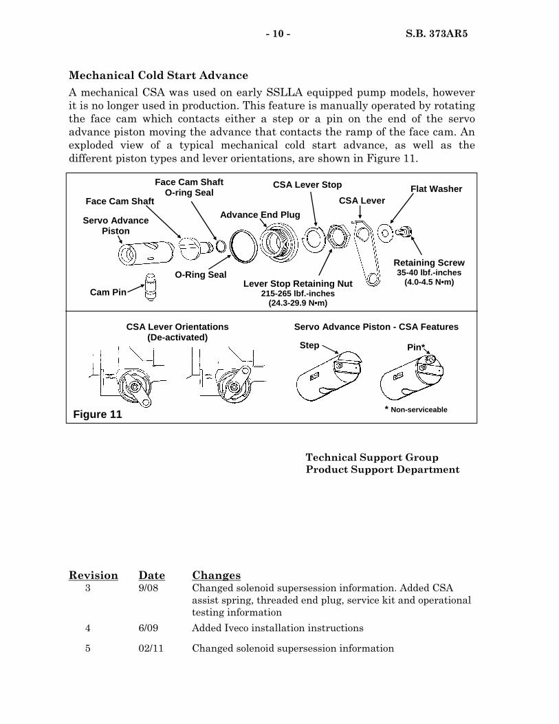
Revision Date Changes 3 9/08 Changed solenoid supersession information. Added CSA
assist spring, threaded end plug, service kit and operational testing information
4 6/09 Added Iveco installation instructions
5 02/11 Changed solenoid supersession information
- 10 - S.B. 373AR5
Mechanical Cold Start Advance A mechanical CSA was used on early SSLLA equipped pump models, however it is no longer used in production. This feature is manually operated by rotating the face cam which contacts either a step or a pin on the end of the servo advance piston moving the advance that contacts the ramp of the face cam. An exploded view of a typical mechanical cold start advance, as well as the different piston types and lever orientations, are shown in Figure 11.
* Non-serviceable
Step Pin*
Retaining Screw 35-40 lbf.-inches
(4.0-4.5 N•m) Lever Stop Retaining Nut 215-265 lbf.-inches
(24.3-29.9 N•m)
CSA Lever
CSA Lever Stop Flat Washer
Advance End Plug
Cam Pin
Servo Advance Piston
Face Cam Shaft O-ring Seal
O-Ring Seal
Face Cam Shaft
CSA Lever Orientations (De-activated)
Servo Advance Piston - CSA Features
Figure 11
Technical Support Group Product Support Department


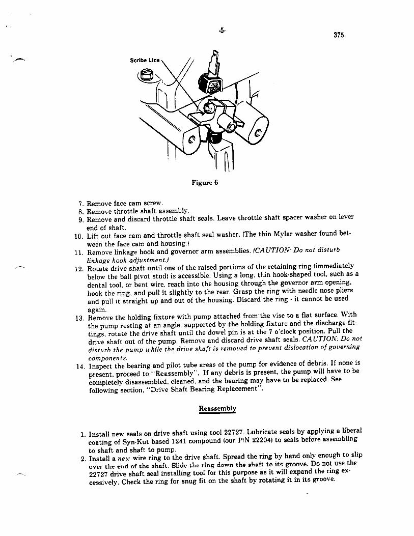

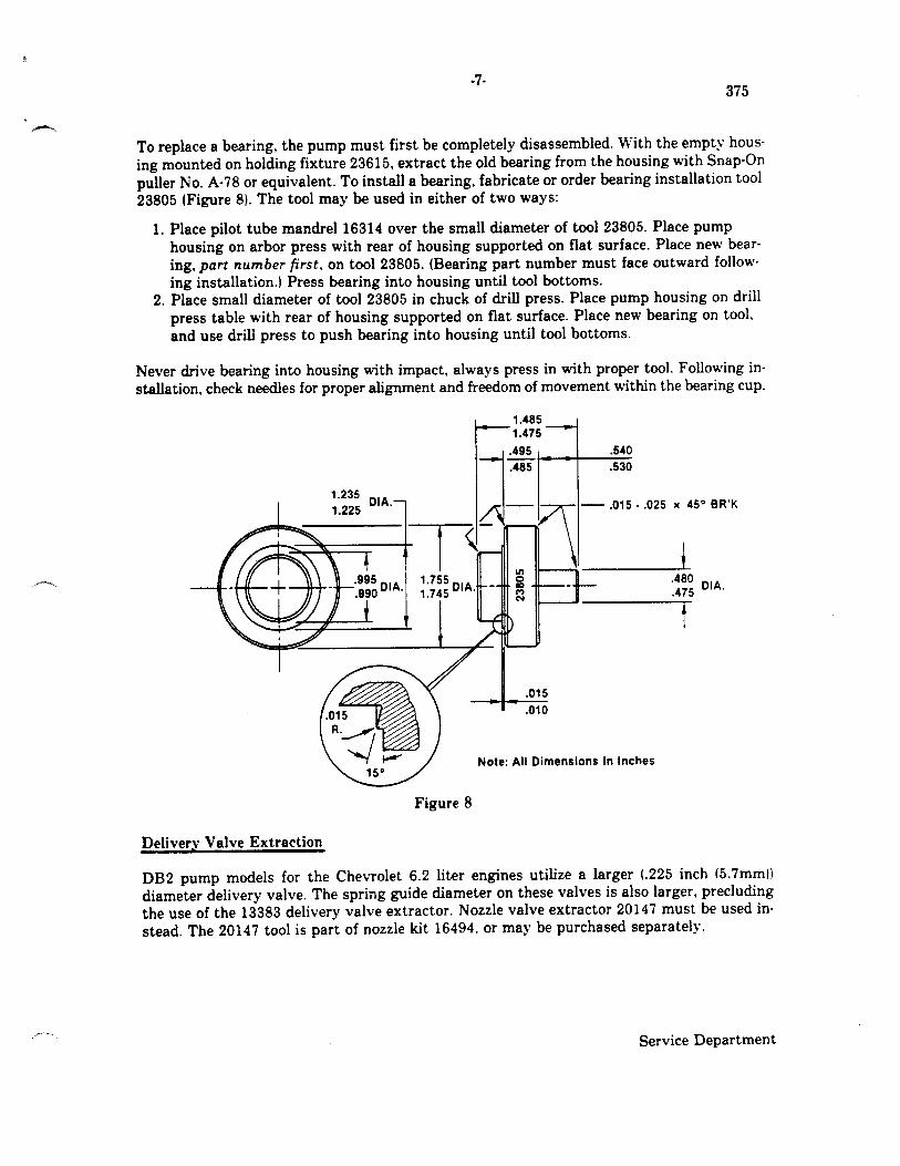

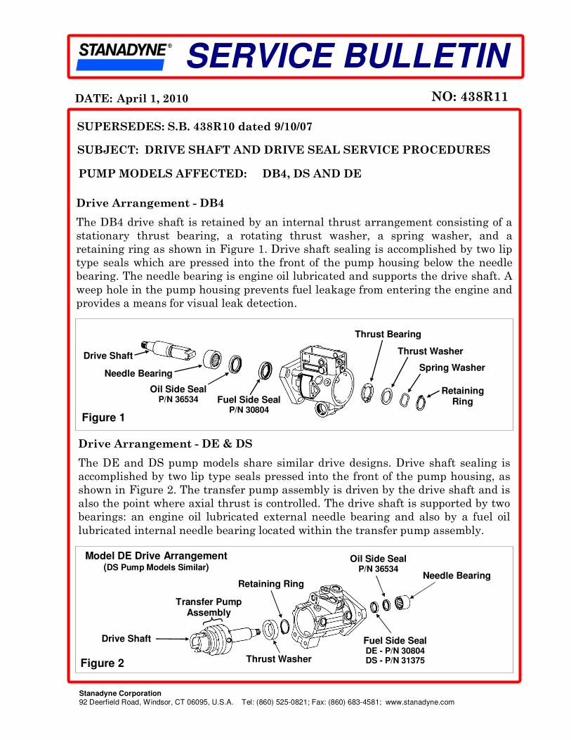
SUBJECT: DRIVE SHAFT AND DRIVE SEAL SERVICE PROCEDURES
NO: 438R11 DATE: April 1, 2010
Stanadyne Corporation 92 Deerfield Road, Windsor, CT 06095, U.S.A. Tel: (860) 525-0821; Fax: (860) 683-4581; www.stanadyne.com
SERVICE BULLETIN
SUPERSEDES: S.B. 438R10 dated 9/10/07
Drive Arrangement - DB4
The DB4 drive shaft is retained by an internal thrust arrangement consisting of a
stationary thrust bearing, a rotating thrust washer, a spring washer, and a
retaining ring as shown in Figure 1. Drive shaft sealing is accomplished by two lip
type seals which are pressed into the front of the pump housing below the needle
bearing. The needle bearing is engine oil lubricated and supports the drive shaft. A
weep hole in the pump housing prevents fuel leakage from entering the engine and
provides a means for visual leak detection.
Drive Shaft
Needle Bearing
Oil Side Seal P/N 36534 Fuel Side Seal
P/N 30804
Thrust Washer
Thrust Bearing
Spring Washer
Retaining Ring
Figure 1
Drive Arrangement - DE & DS
The DE and DS pump models share similar drive designs. Drive shaft sealing is
accomplished by two lip type seals pressed into the front of the pump housing, as
shown in Figure 2. The transfer pump assembly is driven by the drive shaft and is
also the point where axial thrust is controlled. The drive shaft is supported by two
bearings: an engine oil lubricated external needle bearing and also by a fuel oil
lubricated internal needle bearing located within the transfer pump assembly.
PUMP MODELS AFFECTED: DB4, DS AND DE
Figure 2
Fuel Side Seal DE - P/N 30804 DS - P/N 31375
Needle Bearing
Model DE Drive Arrangement (DS Pump Models Similar)
Retaining Ring
Thrust Washer
Drive Shaft
Transfer Pump Assembly
Oil Side Seal P/N 36534

- 2 - S.B. 438R11
IMPORTANT! Only use the seals called for on the individual service
specification. Improper seal usage can lead to premature seal failure.
Fuel Side Seals
Fuel side seals in DS pump models are a dual lip type (P/N 31375) with a black
metal casing that incorporates a molded polymer sealing surface on the outer
case wall (Figure 3a). Pump models DE and DB4 use a Teflon® lip type fuel seal
(P/N 30804). This seal has a blue sealant bonded to the outer diameter of the
metal case (Figure 3b). Both fuel seals share common service procedures.
Oil Side Seals
When the DE pump model was introduced, it contained a unique oil seal (P/N
35494) which was slightly larger at the outside diameter and had a orange case.
This seal was replaced in 2004 by the oil side seal (P/N 36534) which is used in
all DE, DS and DB4 pump models.
To prevent seal distortion during assembly, an installation sleeve (P/N 39197 or
P/N 39989) is used in conjunction with the 33421 seal and bearing installation
tool. Sleeve selection is determined by the pilot length on the pump housing
(Figure 4). Refer to the Seal and Bearing Installation section of this Service
Bulletin for additional information on service tools and assembly procedures.
Seal Spacers
Early DB4 and DS pumps were fitted with a white polymer spacer (P/N 30445)
between the fuel seal and the oil seal to prevent seal movement within the
housing. In the late 1990’s, the spacer was eliminated as seal retention
properties were improved.
Needle Bearings
All DS, DE, and most DB4 pump models have a housing with a standard length
mounting pilot (Figure 4) and use the same needle bearing assembly. Some
DS Fuel Seal (P/N 31375)
DB4 & DE Fuel Seal (P/N 30804)
Figure 3a Figure 3b
Garter Spring
Black Metal Case
Seal Lips
Molded Sealing Surface
Teflon Lip
Blue Sealant
Metal Case

- 3 - S.B. 438R11
DB4 pump models use a housing with an extended length pilot and a longer
needle bearing (P/N 40018). The service tools are the same for both needle
bearings. However, the removal procedures differ as described herein.
Removing Drive Shaft, Seals and Needle Bearing
Drive shaft removal is required to service the seals and bearings in DB4, DE
and DS pump models. Complete disassembly, inspection, and assembly
procedures are provided in the applicable Operation and Instruction Manual:
DB4 (P/N 99689), DS (P/N 99646), and DE (P/N 99807).
The bearing and seal puller (P/N 28311), as
shown in Figure 5, is used to remove both
drive shaft seals, the seal spacer (if applicable)
and the needle bearing. For DE and DS pump
models, as well as standard length pilot DB4
pump models removal of the seals and bearing
can be performed simultaneously in one
operation. Those DB4 pump models with
extended pilot housings require the bearing
and seals to be removed in separate operations
as follows:
1. Back the outer nut out to the end of the jack screw. Back the inner nut out
until the jaws can be retracted. Insert tool jaws into the drive bore of the
pump housing (Figure 6a), through the center of the bearing and align/
center the puller base on the pilot boss of the pump housing.
2. Holding the inner nut stationary, turn the jack screw to expand the jaws.
Position the puller jaws so that they are in the gap between the oil seal and
the needle bearing so that the lip is in contact with the bottom of the bearing
cage (Figure 6b). Do not over tighten. Remove the needle bearing by holding
the jack screw stationary and tightening the outer nut.
3. Disassemble the P/N 28311 bearing and seal puller (Figure 6c). Retract the
jaws, as in Step 1. Insert jaw assembly into the drive bore. Align the puller
base with the pilot. Push jack screw thru the center hole and install washer
and outer nut.
Puller Jaws
Figure 5
Jack Screw
Puller Base
Outer Nut
Inner Nut
Bearing and Seal Puller P/N 28311
Figure 4 Needle Bearing P/N 40018
Extended Length Pilot
Pump Housing Mounting Flange
Oil Seal
Needle Bearing P/N 26359
Fuel Seal Standard
Length Pilot

- 4 - S.B. 438R11
Seal and Bearing Installation
Both seals and the needle bearing are press fit into the pump housing. Place the
pump housing on an arbor press with the housing flange facing upwards.
NOTE: Ensure the housing rests flat on the arbor plate and that the seal bore of
the housing is clean and dry.
4. Expand the puller jaws under the seals (Figure 6d). Hold the jack screw
stationary, tighten the outer nut to remove both seals (Figure 6e).
IMPORTANT! The seals and bearing are damaged during the removal
process. Never reuse seals or bearings once removed from housing.
Seal and Bearing Installation Tool
The Seal and Bearing Installation Tool (P/N 33421), shown in Figure 7, is used
for all DB4, DS and DE pump models to ensure correct seal positioning. Oil seal
installation sleeve (P/N 39197) is used for all DS, DE and standard length
piloted DB4 pump models. For the extended length pilot DB4 pump models,
there is separate extension adapter for the fuel seal (P/N 38366) and an
extension sleeve for the oil seal (P/N 39989).
Seal and Bearing Installation Tool P/N 33421
Figure 7
Internal O-Ring (P/N 26126) Not Shown
P/N 39989 P/N 39197
Fuel Seal Extension
P/N 38366 P/N 33432
O-Ring Oil Seal Installation Sleeves
Figure 6
Puller (P/N 28311) Disassembled
Seals Removed From Housing
Puller Jaws Expanded
a
Gap
Puller Jaws Bearing
Oil Seal
Fuel Seal
Puller Jaws Retracted
b c d e

- 5 - S.B. 438R11
Fuel Side Seal
1. Place the appropriate fuel seal onto the end of the 33421 installation tool or
the 38366 extension, as required. The seal case faces the tool and the open
side of the seal (lip/garter spring side) faces outward.
NOTE: When installing the fuel seal, ensure the 39197 oil seal installation sleeve
is removed from the 33421 seal and bearing installation tool to avoid damage to
the thin lip of the sleeve.
2. Position the tool and seal above the pump housing as shown in Figure 8.
Guide the tool and seal into the housing bore and press the seal down until
the tool flange bottoms against the pump housing.
Oil Side Seal
1. Select the proper oil seal installation sleeve and insert it onto the end of the
33421 seal and bearing installation tool. Place the open side of the seal (lip/
garter spring side) over the lip of the installation sleeve so that the seal sits
squarely.
2. Guide the seal and tool into the pump housing as shown in Figure 9 and
press the seal in until the flange on the tool bottoms against the housing.
Drive Shaft Needle Bearing
1. Remove the oil seal sleeve (P/N 39197 or 39989) from the end of the 33421
seal and bearing installation tool. Slide the bearing onto the tool in place of
the sleeve with the bearing part number facing toward the tool shoulder.
Guide the bearing into the housing as shown in Figure 10 and press it in
until the flange on the tool bottoms against the housing.
Fuel Seal P/N 30804 or P/N 31375
Arbor Press
Figure 8
Housing Assembly (DB4 Shown)
Seal and Bearing Installation Tool P/N 33421
Fuel Seal Extension (If Applicable) P/N 38366
Figure 9
Oil Side Seal P/N 36534
Housing Assembly (DB4 Shown)
Arbor Press
Seal and Bearing Installation Tool P/N 33421 Oil Seal Installation Sleeve
P/N 39197 or P/N 39989

- 6 - S.B. 438R11
IMPORTANT: When installed correctly, the drive shaft needle bearing
will protrude approximately .045 inches (1.14 mm) from the end of the
housing - this is a normal condition.
NOTE: Some DB4 pump models used on VM Motori pump applications are not
equipped with a drive bearing. Reference Service Bulletin 478 for specific service
and bench testing information regarding these pump models
Drive Shaft and Thrust Component Assembly
There is a specific drive shaft seal protection tube used for each pump type.
Figure 11 shows a typical DB4 drive shaft installation. As an assembly aid,
moisten both drive shaft and seal protection tube with calibrating fluid prior to
installation. Refer the respective Operation and Instruction Manual: DB4 (P/N
99689), DS (P/N 99646), and DE (P/N 99807) for applicable instructions and
specific tooling required during drive component assembly.
IMPORTANT: Do not tilt the housing rearward (head bore down)
without the head and rotor assembly installed and secured. The drive
shaft and thrust components could fall out of the housing through the
head bore.
Re-use of Drive Shafts
During normal pump operation, seal lip contact creates witness marks on the
drive shaft (Figure 12). Re-using a drive shaft with new seals is an acceptable
Figure 10 Arbor Press
Housing Assembly (DB4 Shown)
Needle Bearing P/N 26359 or P/N 40018
Seal and Bearing Installation Tool P/N 33421
Figure 11 Install in this direction
Insert Drive Shaft until this edge is flush with the Needle Bearing
DB4 Seal Protection Tube
P/N 32957
Drive Shaft
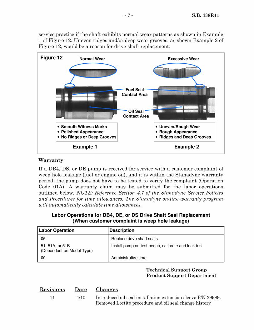
Labor Operations for DB4, DE, or DS Drive Shaft Seal Replacement (When customer complaint is weep hole leakage)
Labor Operation Description
06 Replace drive shaft seals
51, 51A, or 51B (Dependent on Model Type)
Install pump on test bench, calibrate and leak test.
00 Administrative time
Revisions Date Changes
11 4/10 Introduced oil seal installation extension sleeve P/N 39989.
Removed Loctite procedure and oil seal change history
- 7 - S.B. 438R11
Figure 12
Fuel Seal Contact Area
Oil Seal Contact Area
Example 2
Normal Wear Excessive Wear
Example 1
• Smooth Witness Marks
• Polished Appearance
• No Ridges or Deep Grooves
• Uneven/Rough Wear
• Rough Appearance
• Ridges and Deep Grooves
service practice if the shaft exhibits normal wear patterns as shown in Example
1 of Figure 12. Uneven ridges and/or deep wear grooves, as shown Example 2 of
Figure 12, would be a reason for drive shaft replacement.
Warranty
If a DB4, DS, or DE pump is received for service with a customer complaint of
weep hole leakage (fuel or engine oil), and it is within the Stanadyne warranty
period, the pump does not have to be tested to verify the complaint (Operation
Code 01A). A warranty claim may be submitted for the labor operations
outlined below. NOTE: Reference Section 4.7 of the Stanadyne Service Policies
and Procedures for time allowances. The Stanadyne on-line warranty program
will automatically calculate time allowances.
Technical Support Group
Product Support Department

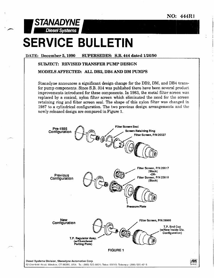
NO: 444Rl
_,-.
SERVICE BULLETIN ’ DATE: December 5,199O SUPERSEDES: S.B. 444 dated l/26/90
SUBJECT: REVISED TRANSFER PUMP DESIGN
MODELS AFFECTED: ALL DB2, DB4 AND DM PUMPS
Stanadyne announces a significant design change for the DB2, DM, and DB4 trans- fer pump components. Since S.B. 314 was published there have been several product improvements introduced for these components. In 1983, the metal filter screen was replaced by a conical, nylon filter screen which eliminated the need for the screen retaining ring and filter screen seal. The shape of this nylon filter was changed in 1987 to a cylindrical configuration. The two previous design arrangements and the newly released design are compared in Figure 1.
Pre-1985 Configuration
Filter Screen Seal
Screen Retaining Ring
Filter Screen, P/N 20527
/+-a_/ Filter Screen, P/N 26617 (Black)
Previous fl &z=% Configuration -
- h5iY w
-OR-.
/ Filter Screen, P/N 23819
(Black)
Pressure Plate
New Configuration
T.P. Regulator Assy. ’ (w/Chamfered Porting Plate)
FIGURE 1
Diesel Systems Division, Stanadyne Automotive Corp. 12 Deerfield Road, Windsor, CT 06095, USA Tel: (860) 525.0821; Telex: 99218; Telecopy: (860) 525.4215
i
-
j
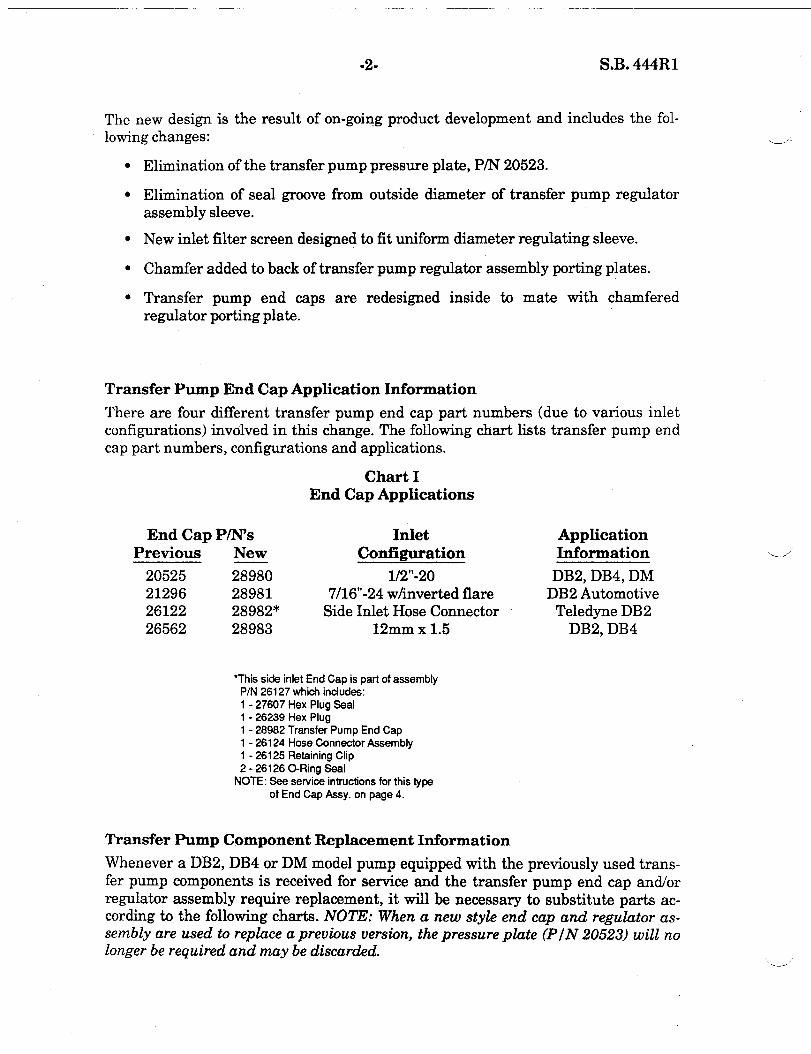
-29 S.B. 444Rl
The new design is the result of on-going product development and includes the fol- lowing changes:
Elimination of the transfer pump pressure plate, P/N 20523.
Elimination of seal groove from outside diameter of transfer pump regulator assembly sleeve.
New inlet filter screen designed to fit uniform diameter regulating sleeve.
Chamfer added to back of transfer pump regulator assembly porting plates.
Transfer pump end caps are redesigned inside to mate with chamfered regulator porting plate.
Transfer Pump End Cap Application Information
There are four different transfer pump end cap part numbers (due to various inlet configurations) involved in this change. The following chart lists transfer pump end cap part numbers, configurations and applications.
Chart I End Cap Applications
End Cap P/N’s Inlet Previous New Configuration
20525 28980 l/2”-20 21296 28981 7/16”-24 w/inverted flare 26122 28982* Side Inlet Hose Connector 26562 28983 12mm x 1.5
Application Information
DB2, DB4, DM DB2 Automotive
Teledyne DB2 DB2, DB4
*This side inlet End Cap is part of assembly P/N 26127 which includes: 1 - 27607 Hex Plug Seal 1 - 26239 Hex Plug 1 - 28982 Transfer Pump End Cap 1 - 26124 Hose Connector Assembly 1 - 26125 Retaining Clip 2 - 26126 O-Ring Seal
NOTE: See service intructions for this type of End Cap ksy. on page 4.
Transfer Pump Component Replacement Information
Whenever a DB2, DB4 or DM model pump equipped with the previously used trans- fer pump components is received for service and the transfer pump end cap and/or regulator assembly require replacement, it will be necessary to substitute parts ac- cording to the following charts. NOTE: When a new style end cap and regulator as- sembly are used to replace a previous version, the pressure plate (PIN 20523) will no longer be required and may be discarded.

- 3- S.B., 444Rl
.-
Chart II Regulator Assembly/End Cap Replacement
Old T.P. New T.P.
Regulator P/N% Regulator P/N?3
19912 28987
21200 28988
Used With
T.P. End Caps
20525
21296
26122
26562
Used With
T.P. End Caps
28980
28981
28982
28983
Chart III Inlet Filter Screen Replacement
Present Filter If Filter If End Cap &
PIN Style Change Only Reg. Assy. Changes -- - 20527 metal 26617 28986 (blue) 23819 conical nylon (black) ,t 11
26617 cylindrical nylon (black) ” 11
Installation of New Transfer Pump Components
1.
2.
3.
4.
Install the 27608 transfer pump seal in the head counterbore.
After the transfer pump liner, blades, springs, retainers and locating ring are installed, place the inlet filter on the transfer pump regulator assembly.
Install the transfer pump regulator assembly with rollpin located in the rollpin hole in the head.
Coat the beveled surface on the inside of the transfer pump end cap (at contact point shown in Figure 3) and the end cap threads with Lubriplate #63OAA grease or equivalent.
Chamfered
Inlet Filter
FIGURE 3

5. Assemble the end cap to the head.. Apply light pressure to top of end cap and rotate counter-clockwise until a slight “click” is heard. Then turn the cap clockwise until hand tight.
6. Tighten the end cap to 360-440 lbf.-inches (40.7-49.7 Nom) using a P/N 20548 end cap socket wrench.
7. Install end cap locking plate, seal and screw (Ref. S.B. 408Rl).
4 S.B. 444Rl
Assembly Instructions for Side Inlet End Cap Assemblies (End Caps 26122 & 28982)
After completing steps l-7 above, assemble side inlet cap components as follows:
1.
2.
3.
Hex Plug and Hex Plug Seal
Hose Connector . Assembly
Retaining _& Ring
FIGURE 4
Position seals, 26126, into hose connector assembly and lubricate lightly with Syn-Kut lubricant, P/N 22204. Install hose connector assembly to end cap.
Seat retaining clip into groove in end cap.
Place hex plug seal, 27607, on hex plug (Refer to Figure 4). Screw hex plug into end cap and tighten to 75-100 lbf.-inches (8.5-11.3 Nem) using a 3/16 inch hex bit.
Technical Support Group Product Support Department
Revision 1
Date 12/4/90
Changes Removed reference to “D-shaped” transfer pump end cap seal


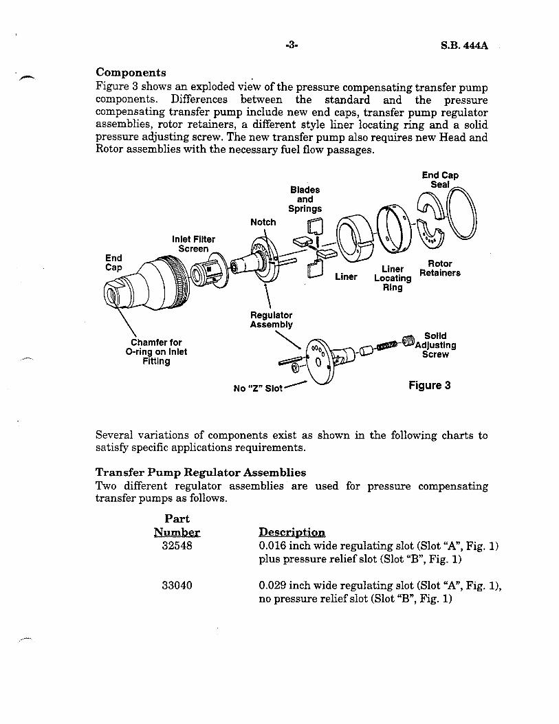
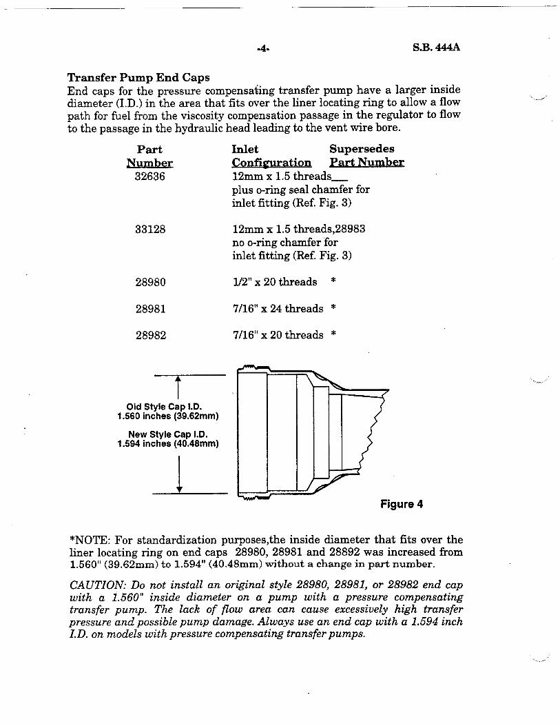

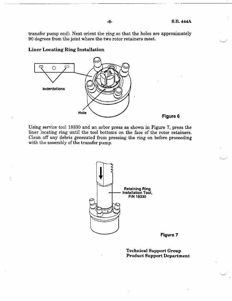

NO: 462
SERVICE BULL Date: April 21,199l
SUBJECT: FIELD CONVERSIONS OF D SERIES PUMPS FOR OPERATION WITH EXTERNAL ELECTRONIC GOVERNORS
As you may know, Stanadyne’s fuel injection pumps equipped with speed droop governors offer governor regulation of 3-5%, which is more than adequate for most close governor applications. There is, however, a small but increasing number of applications which require isochronous (zero droop) governing. Isochronous or precise governing can be attained by connecting one of several commercially available brands of external electronic governors by linkage to the shut-off lever of a Stanadyne “D” series pump equipped with either an all speed or speed droop governor.
NOTE: Never attempt to connect an external electronic governor to the throttZe lever of a Stanadyne injection pump. Poor performance and/or rapid wear of pump governor components could result.
The following information has been compiled for our service network to allow for the necessary modifications required to adapt our pumps for external governor operation.
Service Kits
Two service kits are available to help facilitate these field conversions. Kit, 29375, shown in Figure 1, contains the necessary components for pumps which were not equipped with a shut-off shaft assembly as part of the original equipment. Kit 29338, shown in Figure 2, contains the necessary components for pumps equipped a shut-off shaft assembly as original equipment. Refer to the individual pump specification to determine which part changes are required, and which kit, if any, is appropriate to implement this conversion. Some applications may only require a roller-type shut-off cam to complete the conversion and in such cases a service kit would not be required.
CONTENTS OF KIT 29375 CONTENTS OF KIT P/N 29338
P/N P/N Description
11582
Description ZY !zY Washer, Lever Ret.Screw 11582 Washer, Lever Ret. Screw 1
12049 Washer, Lever Pos. Screw 1 12049 Washer, Lever Pos. Screw 1 12051 Screw, Lever Pos. 1 12051 Screw, Lever Pos. 12167 Screw, Adj.
z 12167 Screw, Adj. :
12173 Nut, Adj. Screw 12173 Nut, Adj. Screw 2 12237 Shut-off Shaft
i 12992 Lever
12992 Lever 12998 Screw, Lever Retaining 1 12998 Screw, Lever Retaining 14408 Mylar Washer :
14966 Cam Ass Shut-off Roller 1 27244’ Gasket, ontrol Cover J1
14966 17438
Ca; Assy, Shut-off Roller : l Not Shown
27244’ Gasket, Control Cover 1
* Not Shown
Diesel Systems Division, Stanadyne Automotive Corp. 92 Deerfield Road, Windsor, CT 06095, USA Tel: (203) 5250821; Telex: 99218; Telecopy: (203) 525-4215
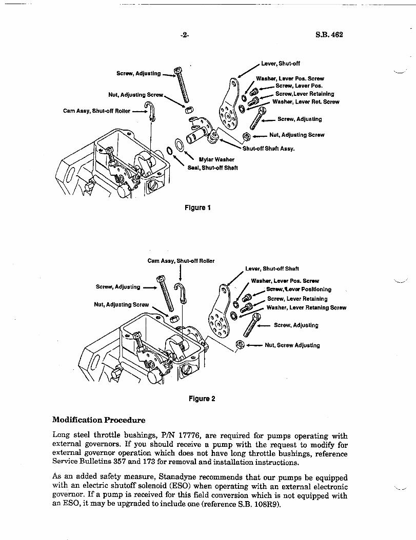
-2- S.B. 462
Screw, Adjusting
Nut, Adjusting Screw
Cam Assy, Shut-off Roller
asher, Lever Pos. Screw Screw, Lever Pos.
- Screw,Lever Retaining Washer, Lever Ret. Screw
Screw, Adjusting
_ Nut, Adjusting Screw
hut-off Shaft Assy.
Seal, Shut-off Shaft
Figure 1
Cam Assy, Shut-off Roller
Screw, Adjusting
Nut, Adjusting Screw
Lever, Shut-off Shaft
sher, Lever Pos. Screw
sdrew,tever Positioning
Screw, Lever Retaining
Washer, Lever Retaning Screw
Screw, Adjusting
- Nut, Screw Adjusting
Figure 2
Modification Procedure
Long steel throttle bushings, P/N 17776, are required for pumps operating with external governors. If you should receive a pump with the request to modify for external governor operation which does not have long throttle bushings, reference Service Bulletins 357 and 173 for removal and installation instructions,
As an added safety measure, Stanadyne recommends that our pumps be equipped with an electric shutoff solenoid (ESO) when operating with an external electronic governor. If a pump is received for this field conversion which is not equipped with an ESO, it may be upgraded to include one (reference S.B. lOSR9).
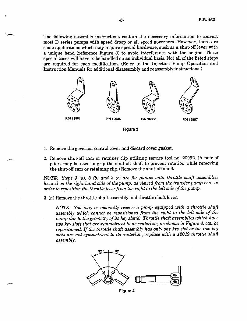
-3- S.B. 462 9
’ .-
1.
__. 2.
The following assembly instructions contain the necessary information to convert most D series pumps with speed droop or all speed governors. However, there are some applications which may require special hardware, such as a shut-off lever with a unique bend (reference Figure 3) to avoid interference with the engine. These special cases will have to be handled on an individual basis. Not all of the listed steps are required for each modification. (Refer to the Injection Pump Operation and Instruction Manuals for additional disassembly and reassembly instructions.)
PM 12981 P/N 12985 PRJ 16083 P/N 12987
Figure 3
Remove the governor control cover and discard cover gasket.
Remove shut-off cam or retainer clip utilizing service tool no. 20992. (A pair of pliers may be used to grip the shut-off shaft to prevent rotation while removing the shut-off cam or retaining clip.) Remove the shut-off shaft.
NOTE: Steps 3 (a), 3 (b) and 3 (c) are for pumps with throttle shaft assemblies located on the right-hand side of the pump, as viewed from the transfer pump end, in order to reposition the throttle lever from the right to the left side of the pump.
3. (a) Remove the throttle shaft assembly and throttle shaft lever.
NOTE: You may occasionally receive a pump equipped with a throttle shaft assembly which cannot be repositioned from the right to the left side of the pump due to the geometry of its key slot(s). Throttle shaft assemblies which have two key slots that are symmetrical to its centerline, as shown in Figure 4, can be repositioned. If the throttle shaft assembly has only one key slot or the two key slots are not symmetrical to its centerline, replace with a 12019 throttle shaft assembly.
Figure 4
-4- S.B. 462
3. (b) Install a new 14408 Mylar washer and 17438 throttle shaft seal. Reverse positions of the high and low idle adjusting screws in the lever.
3. (c) Reinstall the throttle shaft assembly partially through its bore on the left side
4.
5.
6.
7,
8.
9.
of the pump housing (viewed from the transfer pump end). Slide the throttle shaft lever onto the throttle shaft assembly by engaging the key in the throttle lever bore with the throttle shaft key slot which is closest to the transfer pump end of the pump. Complete the throttle shaft assembly installation with a slight rotary motion to prevent seal damage. The forked end of the throttle shaft lever must straddle the guide stud on pumps equipped with all speed governors and straddle the flats on the control rod guide bushing on pumps equipped with speed droop governors (ref. S.B. 97R2).
Install a 12237 shut-off shaft assembly with a new 17438 shut-off shaft seal and a 14408 Mylar washer. Check linkage gap and readjust if necessary before installing a new shut-off roller cam assembly.
Install a 14966 roller-type shut-off cam assembly with the straight inner edge engaging the slot in the shut-off shaft assembly. The roller cam will snap into position when installed correctly.
Install the 12167 shut-off shaft assembly adjusting screws and the 12173 adjusting screw locking nuts onto the shut-off shaft assembly.
Align the center holes of the adjustable shut-off lever and shut-off shaft assembly as shown in figure 1. Secure in position with a 12998 lever retaining screw and 11582 washer. Position the lever in the Ll-L position unless otherwise indicated (ref. S.B. 164) with a 12051 lever positioning screw and a’12049 washer. Tighten the lever positioning screw to 25 - 30 lbf-in (2.8 - 3.4 Nom) and the lever retaining screw to 35 - 40 lbf-in (4.0 - 4.5 Nom).
Rotate the shut-off lever toward the transfer pump end and adjust the transfer pump end adjusting screw until the long leg of the roller cam is in a vertical position (there should be no contact between the linkage hook and roller cam). Rotate the lever toward the flange end and adjust the flange end adjusting screw until the long cam leg is at an angle of approximately 60 degrees from vertical, Tighten the adjusting locknuts to 35 - 40 lbf-in (4.0 - 4.5 Nom).
Reinstall governor control cover with a new 27244 control cover gasket. Tighten the three governor control cover screws to 35 - 45 lbf-in (4.0 - 5.1 Nom).
Calibration Procedure
1.
2.
Recalibrate to original pump specification.
Following normal pump calibration, adjust the high idle screw to obtain the specified high idle fuel delivery at 10% above the rated ERPM (adjust speed droop to minimum droop position on pumps equipped with speed droop governors). [Example: 1800 x .lO = 180 + 1800 = 1980 ERPMI This ensures that the pump’s mechanical governor will not interfere with the electronic governor.
3.
4.
45 S.B. 462
Check for a maximum of 4mm /stroke @ 400 ERPM and rated ERPM with the shut-off shaft assembly in the full off position, Adjust if necessary (reference step number 8 of the modification procedure).
Seal the shut-off shaft adjusting screws together with a 10408 sealing wire as outlined in Service Bulletin 134 following pump calibration.
Identification
Identify each modified pump by stamping “S.B. 462” on the nameplate below the pump model number.
warranty
These conversions are to be made at the request and expense of the customer only. Stanadyne will not accept warranty claims for these modifications.
Technical Support Group Product Support Department


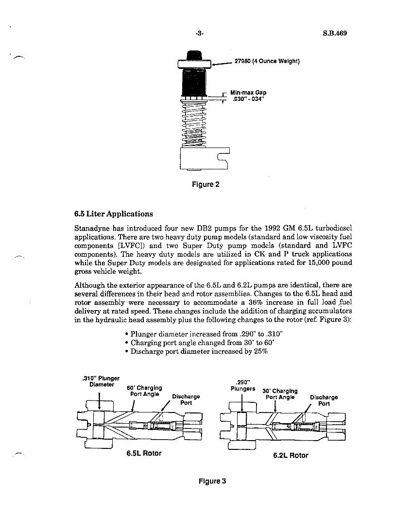
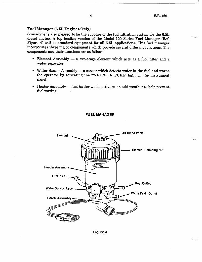


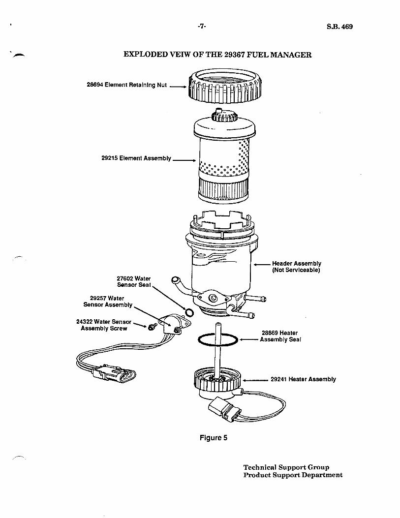


DATE: October 23, 2006 Supersedes: S.B. 483R2 dated 3/19/03
SERVICE BULLETIN
NO: 483R4
Stanadyne Corporation 92 Deerfield Road, Windsor, CT 06095, U.S.A. Tel: (860) 525-0821; Fax: (860) 683-4581; www.stanadyne.com
SUBJECT: WOODWARD DYNA 70025 INTEGRATED ACTUATOR FOR STANADYNE FUEL INJECTION PUMPS
The Woodward DYNA 70025 electronic governing system has been used in conjunction with Stanadyne “D” Series mechanically governed injection pumps for both production and the aftermarket since the mid-1990’s. This governing system (Reference Figure 1) is easily adapted to mechanically governed “D” Series pumps where closer governor regulation than what the mechanical governor can provide is desired.
PUBLICATIONS REFERENCES: SERVICE BULLETINS 462, 509R2
The electronic governing system consists of a rotary actuator, which replaces the standard governor cover, plus engine mounted electronic controls. The Woodward Governor Company manufactures several variants of the DYNA 70025 pump mounted electronic actuator. However, only three are available from Stanadyne - two 12 volt actuators (internally sealed actuator shaft and non-sealed shaft versions) and one 24 volt actuator (sealed actuator shaft) version, as shown in the table in the following page.
DYNA 70025 Integrated Actuator
Assembly
Electronic Engine
Controller
Figure 1

- 2 - S.B. 483R4
Stanadyne Part Number
Woodward and Barber Coleman Part Numbers
Actuator Voltage Type Customer
33824
DYNC-70025-000-0-12 DYNC-70025-000-1-12 DYNC-70025-000-0-12 DYNC-70025-001-1-12 DYNC-70025-003-1-12 DC 70025-003-012 DC 70025-003-112
12 Sealed Cummins
33825
DYNC-70025-000-0-24 DYNC-70025-000-1-24 DYNC-70025-001-0-24 DYNC-70025-001-1-24 DYNC-70025-003-1-24 DC 70025-003-024 DC 70025-003-124
24 Sealed Cummins
34796 DYNC-70025-200-2-12 DYNC-70025-201-2-12 DC 70025-201-212
12 Standard Perkins
NOTE: The DYNA 70025 electronic governing system was originally manufactured by the Barber Colman Governor Company. Part numbers for both manufacturers are represented in the table above . The engine controls and other actuators available from Woodward are not available from Stanadyne. Additional information on these components is available through the Woodward Governor Company, at the following address:
Woodward Governor Company 6250 West Howard Street Niles, IL 60714-3433 Phone: 1(847)967-7730 www.woodward.com
Governor Operation The actuator consists of a electric coil and a lever arm which contacts the pumps governor linkage to control engine speed. As engine speed varies with load, the electronic control unit varies the current to the pump mounted actuator which in turn repositions the linkage and metering valve. Testing Pumps With the DYNA 70025 Actuator Pumps received for service that have a DYNA 70025 Actuator installed, should be serviced as follows. 1. Compare the part number on the actuator manufacturers label to the table
above to determine whether the actuator is a 12 or 24 volt model. 2. With the pump mounted on the test bench, connect the leads from your
voltage supply (12 or 24 volts DC as applicable) to the two center terminal screws on the terminal strip of the actuator (Ref. Fig. 3).
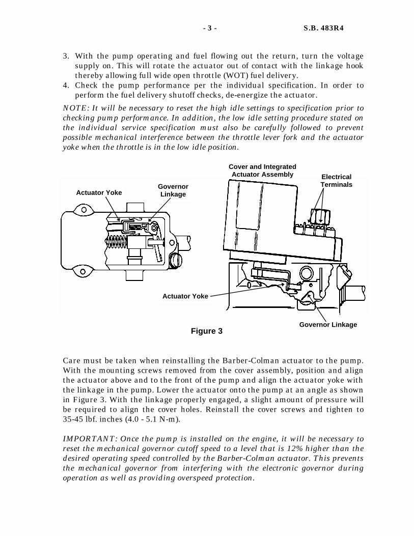
- 3 - S.B. 483R4
Actuator Yoke Governor Linkage
Actuator Yoke
Governor Linkage
Electrical Terminals
Cover and Integrated Actuator Assembly
Figure 3
3. With the pump operating and fuel flowing out the return, turn the voltage supply on. This will rotate the actuator out of contact with the linkage hook thereby allowing full wide open throttle (WOT) fuel delivery.
4. Check the pump performance per the individual specification. In order to perform the fuel delivery shutoff checks, de-energize the actuator.
NOTE: It will be necessary to reset the high idle settings to specification prior to checking pump performance. In addition, the low idle setting procedure stated on the individual service specification must also be carefully followed to prevent possible mechanical interference between the throttle lever fork and the actuator yoke when the throttle is in the low idle position.
Care must be taken when reinstalling the Barber-Colman actuator to the pump. With the mounting screws removed from the cover assembly, position and align the actuator above and to the front of the pump and align the actuator yoke with the linkage in the pump. Lower the actuator onto the pump at an angle as shown in Figure 3. With the linkage properly engaged, a slight amount of pressure will be required to align the cover holes. Reinstall the cover screws and tighten to 35-45 lbf. inches (4.0 - 5.1 N-m). IMPORTANT: Once the pump is installed on the engine, it will be necessary to reset the mechanical governor cutoff speed to a level that is 12% higher than the desired operating speed controlled by the Barber-Colman actuator. This prevents the mechanical governor from interfering with the electronic governor during operation as well as providing overspeed protection.
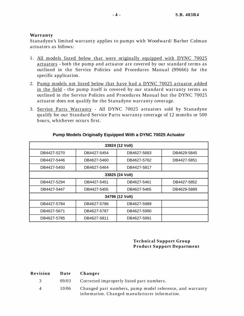
Technical Support Group Product Support Department
Warranty Stanadyne’s limited warranty applies to pumps with Woodward/ Barber Colman actuators as follows: 1. All models listed below that were originally equipped with DYNC 70025
actuators - both the pump and actuator are covered by our standard terms as outlined in the Service Policies and Procedures Manual (99666) for the specific application.
2. Pump models not listed below that have had a DYNC 70025 actuator added in the field - the pump itself is covered by our standard warranty terms as outlined in the Service Policies and Procedures Manual but the DYNC 70025 actuator does not qualify for the Stanadyne warranty coverage.
3. Service Parts Warranty - All DYNC 70025 actuators sold by Stanadyne qualify for our Standard Service Parts warranty coverage of 12 months or 500 hours, whichever occurs first.
- 4 - S.B. 483R4
33824 (12 Volt)
DB4427-5270 DB4427-5454 DB4627-5683 DB4629-5845
DB4427-5446 DB4627-5460 DB4627-5762 DB4427-5851
DB4427-5450 DB4627-5464 DB4427-5817
33825 (24 Volt)
DB4427-5294 DB4427-5451 DB4627-5461 DB4427-5852
DB4427-5447 DB4427-5455 DB4627-5465 DB4629-5889
34796 (12 Volt)
DB4427-5784 DB4627-5786 DB4627-5989
DB4627-5671 DB4627-5787 DB4627-5990
Pump Models Originally Equipped With a DYNC 70025 Actuator
DB4627-5785 DB4627-5811 DB4627-5991
Revision Date Changes
3 09/03 Corrected improperly listed part numbers. 4 10/06 Changed part numbers, pump model reference, and warranty
information. Changed manufacturer information.

DATE: March 16, 2006 SUPERSEDES: S.B. 509R1 dated 11/97
NO: 509R2
Stanadyne Corporation 92 Deerfield Road, Windsor, CT 06095, U.S.A. Tel: (860) 525-0821; Fax: (860) 683-4581; www.stanadyne.com
The ST-125 electronic governing system has been used in conjunction with Stanadyne “D” series pumps for a number of years in both production and the aftermarket. Recently, the Woodward Governor Company decided to discontinue the manufacture of the ST-125 electronic governor actuator. As a result, Stanadyne has introduced two conversion kits that contain Woodward DYNA 70025 type actuators for servicing pumps that require replacement of the originally fitted ST-125 actuator. IMPORTANT: Stanadyne actuator conversion kits include the parts for fuel injection pump governor conversion only. Additional engine control changes are required which are not available from Stanadyne, but must be obtained through Perkins or Woodward. This bulletin outlines the procedures for servicing ST-125 actuator equipped pumps, actuator testing methods, actuator conversion kit contents and conversion procedures.
PUMP MODELS AFFECTED: DB4 - 5198, 5287, 5501, 5520, 5590, 5989, 5990, 5991
SUBJECT: WOODWARD ST125 ELECTRONIC GOVERNOR DISCONTINUATION AND CONVERSION
Description The ST-125 electronic governing system includes an integrated actuator (Reference Figure 1) and a separate analog speed control. The governor uses a bi-directional actuator to rotate a roller type shutoff cam. The cam moves the governor linkage to control metering valve motion for precise fuel delivery control. The original mechanical overspeed protection and electric shut off solenoid are also retained.
SERVICE BULLETIN LIMITED DISTRIBUTION
LIMITED DISTRIBUTION - PERKINS
Figure 1
Gear Clamp P/N 32119
Guide Stud P/N 32115
Retaining Shaft P/N 32116
Roller-type Shutoff Cam P/N 14966
ST-125 Electronic Governor Actuator
P/N 32118

- 2 - S.B. 509R2
Aneroid Shutoff Cam Pump models equipped with both an ST-125 actuator and an aneroid (Reference S.B. 225) have a unique aneroid shutoff cam, as shown in Figure 2, which allows for aneroid operation independent of the governor. As with all shutoff cams, the 34361 aneroid shutoff cam is designed to be installed only once. Therefore, whenever a shutoff cam is removed from a pump it must be discarded and replaced with a new cam.
1. Remove only the governor cover screw that fastens the ST-125 actuator to the governor cover.
2. Rotate the actuator approximately 45 degrees in the upwards direction. Re-install cover screw and tighten to 35-45 lbf-inch (4.0-5.1 N•m).
3. Prior to performing calibration checks, reset the high idle fuel delivery using the guide stud.
4. Remove the torque screw plug and replace it with the torque screw, nut, and seal called out on the individual service specification. This will enable fuel delivery adjustment during calibration checks.
Figure 2
Aneroid Shutoff Cam P/N 34361
Pump Testing Pump Test As Received and Test Following Pump Service are performed while the electronic governor actuator is rotated from its normal operating position, as shown in Figure 3. This places the roller shutoff cam in a position so it does not interfere with linkage travel.
Figure 3
Remove plug and install the torque screw, nut, and seal called out on the individual service specification
Re-set high idle fuel delivery using the guide stud
Remove cover screw, rotate actuator approximately 45˚, and re-install cover screw
NOTE: To prevent possible governor cover interference
and shaft binding, place a 13521 washer under the actuator mounting tang before returning the ST-125 Actuator to its operational position
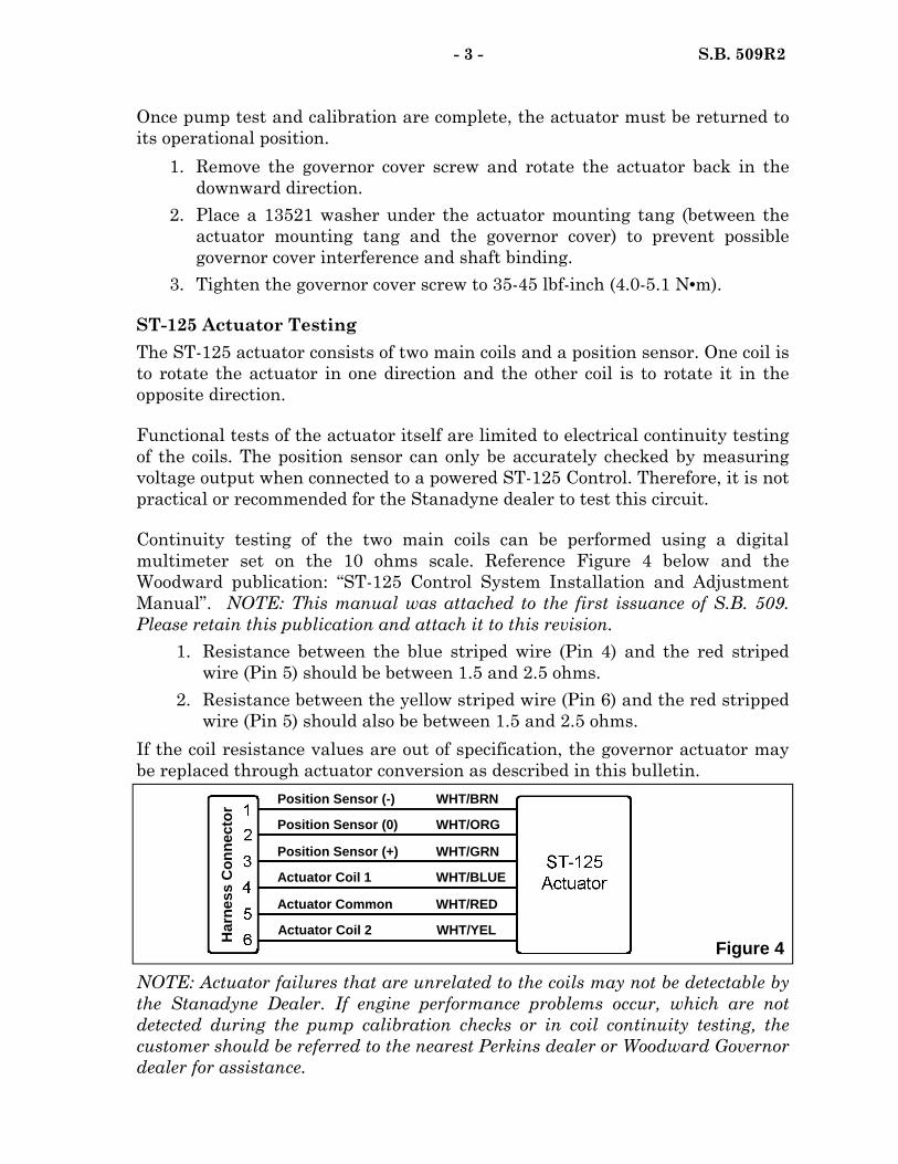
- 3 - S.B. 509R2
Once pump test and calibration are complete, the actuator must be returned to its operational position.
1. Remove the governor cover screw and rotate the actuator back in the downward direction.
2. Place a 13521 washer under the actuator mounting tang (between the actuator mounting tang and the governor cover) to prevent possible governor cover interference and shaft binding.
3. Tighten the governor cover screw to 35-45 lbf-inch (4.0-5.1 N•m). ST-125 Actuator Testing The ST-125 actuator consists of two main coils and a position sensor. One coil is to rotate the actuator in one direction and the other coil is to rotate it in the opposite direction. Functional tests of the actuator itself are limited to electrical continuity testing of the coils. The position sensor can only be accurately checked by measuring voltage output when connected to a powered ST-125 Control. Therefore, it is not practical or recommended for the Stanadyne dealer to test this circuit. Continuity testing of the two main coils can be performed using a digital multimeter set on the 10 ohms scale. Reference Figure 4 below and the Woodward publication: “ST-125 Control System Installation and Adjustment Manual”. NOTE: This manual was attached to the first issuance of S.B. 509. Please retain this publication and attach it to this revision.
1. Resistance between the blue striped wire (Pin 4) and the red striped wire (Pin 5) should be between 1.5 and 2.5 ohms.
2. Resistance between the yellow striped wire (Pin 6) and the red stripped wire (Pin 5) should also be between 1.5 and 2.5 ohms.
If the coil resistance values are out of specification, the governor actuator may be replaced through actuator conversion as described in this bulletin.
NOTE: Actuator failures that are unrelated to the coils may not be detectable by the Stanadyne Dealer. If engine performance problems occur, which are not detected during the pump calibration checks or in coil continuity testing, the customer should be referred to the nearest Perkins dealer or Woodward Governor dealer for assistance.
Figure 4
Position Sensor (-) WHT/BRN
Position Sensor (0) WHT/ORG
Position Sensor (+) WHT/GRN
Actuator Coil 1 WHT/BLUE
Actuator Coil 2 WHT/YEL
Actuator Common WHT/RED
Har
ness
Con
nect
or
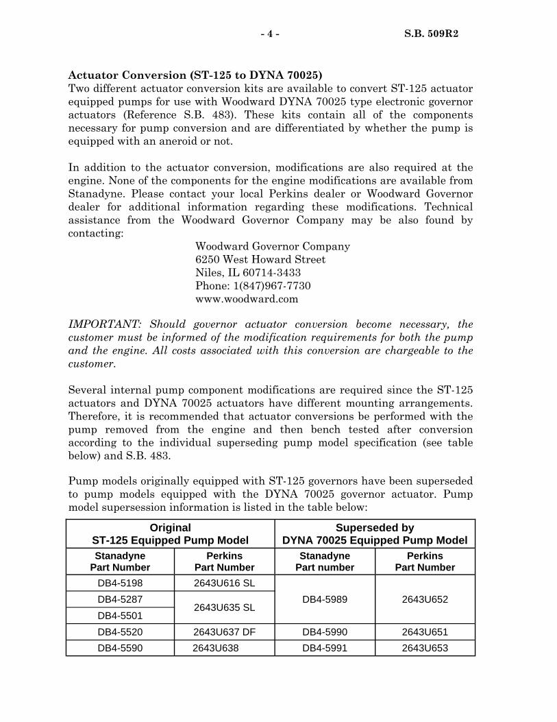
- 4 - S.B. 509R2
Actuator Conversion (ST-125 to DYNA 70025) Two different actuator conversion kits are available to convert ST-125 actuator equipped pumps for use with Woodward DYNA 70025 type electronic governor actuators (Reference S.B. 483). These kits contain all of the components necessary for pump conversion and are differentiated by whether the pump is equipped with an aneroid or not. In addition to the actuator conversion, modifications are also required at the engine. None of the components for the engine modifications are available from Stanadyne. Please contact your local Perkins dealer or Woodward Governor dealer for additional information regarding these modifications. Technical assistance from the Woodward Governor Company may be also found by contacting:
Woodward Governor Company 6250 West Howard Street Niles, IL 60714-3433 Phone: 1(847)967-7730 www.woodward.com
IMPORTANT: Should governor actuator conversion become necessary, the customer must be informed of the modification requirements for both the pump and the engine. All costs associated with this conversion are chargeable to the customer. Several internal pump component modifications are required since the ST-125 actuators and DYNA 70025 actuators have different mounting arrangements. Therefore, it is recommended that actuator conversions be performed with the pump removed from the engine and then bench tested after conversion according to the individual superseding pump model specification (see table below) and S.B. 483. Pump models originally equipped with ST-125 governors have been superseded to pump models equipped with the DYNA 70025 governor actuator. Pump model supersession information is listed in the table below:
Superseded by DYNA 70025 Equipped Pump Model
Stanadyne Part Number
Perkins Part Number
Stanadyne Part number
Perkins Part Number
DB4-5198 2643U616 SL
DB4-5989 2643U652 DB4-5287 2643U635 SL
DB4-5501
DB4-5520 2643U637 DF DB4-5990 2643U651
DB4-5590 2643U638 DB4-5991 2643U653
Original ST-125 Equipped Pump Model

- 5 - S.B. 509R2
Whenever actuator conversion is performed, the pump must be re-identified by replacing the pump name plate with one stamped with the superseding pump model number, corresponding Perkins part number, and any other remaining information from the original name plate, as shown in Figure 5.
When performing actuator conversions, refer to the superseding model number service specification for correct component assembly orientation and any preliminary setting requirements. Use the Actuator Conversion Kit, P/N 38471 to convert electronic actuators on pump models not equipped with an aneroid. The contents of this kit are as follows:
Use the Actuator Conversion Kit, P/N 38470 to convert electronic actuators on pump models equipped with an aneroid. The contents of this kit are shown on the following page.
1800 DB4627-5989
2643U635SL 11105230
Stanadyne Part Number
Perkins Part Number Pump
Serial Number
Rated Speed
Figure 5
38471 Actuator Conversion Kit (For Pump Models without an Aneroid) To convert Pump Models 5501, 5287, 5198 to a 5989
Part number Description Quantity 12165 Screw, hex head 1
12169 Screw, hex head 1
12174 Nut, hex 2
12249 Cam, shutoff 1
14408 Washer, spacer 2
17438 Seal, o-ring 2
26923 Cap, tamper proof 1
27244 Seal, rectangular section 1
27607 Seal, o-ring 1
30788 Cup, cover screw 1
30789 Cap, cover screw 1
34739 Shaft Assy., governor 1
34796 DYNA Actuator Assembly, cover 1

Aneroid Bracket Retention Nut 70-80 lbf.-inch (7.9-9.0 N•m)
Figure 6
38470 Actuator Conversion Kit (Pump Models with Aneroid) To convert Pump Model 5520 to a 5990
And Pump Model 5590 to a 5991
Part number Description Quantity
12165 Screw, hex head 1
12169 Screw, hex head 1
12174 Nut, hex 2
12249 Cam, shutoff 1
14408 Washer, spacer 2
17438 Seal, o-ring 2
26923 Cap, tamper proof 1
27244 Seal, rectangular section 1
27607 Seal, o-ring 1
30788 Cup, cover screw 1
30789 Cap, cover screw 1
34739 Shaft Assy., governor 1
34796 DYNA Actuator Assembly, cover 1
17429 Ring, retaining 2
19116 Washer, spring lock 1
23536 Nut, hex 1
28449 Screw, head locking 1
28627 Bracket, aneroid mounting 1
33609 Lever Assy., adjustable shutoff 1
34361 Cam, aneroid 1
- 6 - S.B. 509R2
The 38470 kit contains an aneroid bracket with a different mounting style from the original pump model. Assemble the aneroid and bracket as shown on the individual service specification and tighten the aneroid bracket mounting nut to 70-80 lbf.-inch (7.9-9.0 N•m), as shown in Figure 6.
Aneroid Bracket
Aneroid Assembly

Revision Date Changes
1 10/97 Removed reference to low idle adjustment. Revised method of rotating the roller shutoff cam out of the way during calibration. Revised Servicing and Warranty Consideration section
2 2/06 Added actuator discontinuation, washer placement, and actuator conversion information. Removed Aftermarket Considerations.
Warranty Stanadyne does not provide warranty coverage for the ST-125 actuator. Therefore, whenever an actuator conversion is performed as outlined in this bulletin, all costs are chargeable to the customer. All components contained in the 38470 and 38471 Actuator Conversion Kits, including the 34796 actuator, are covered by Stanadyne’s Service Parts Warranty (1 year / 500 hours) as outlined in S.L. 301.
Technical Support Group Product Support Department
- 7 - S.B. 509R2


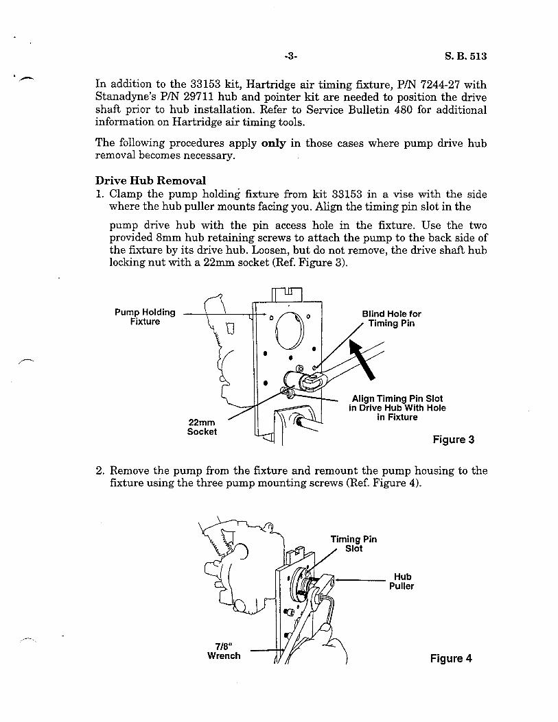
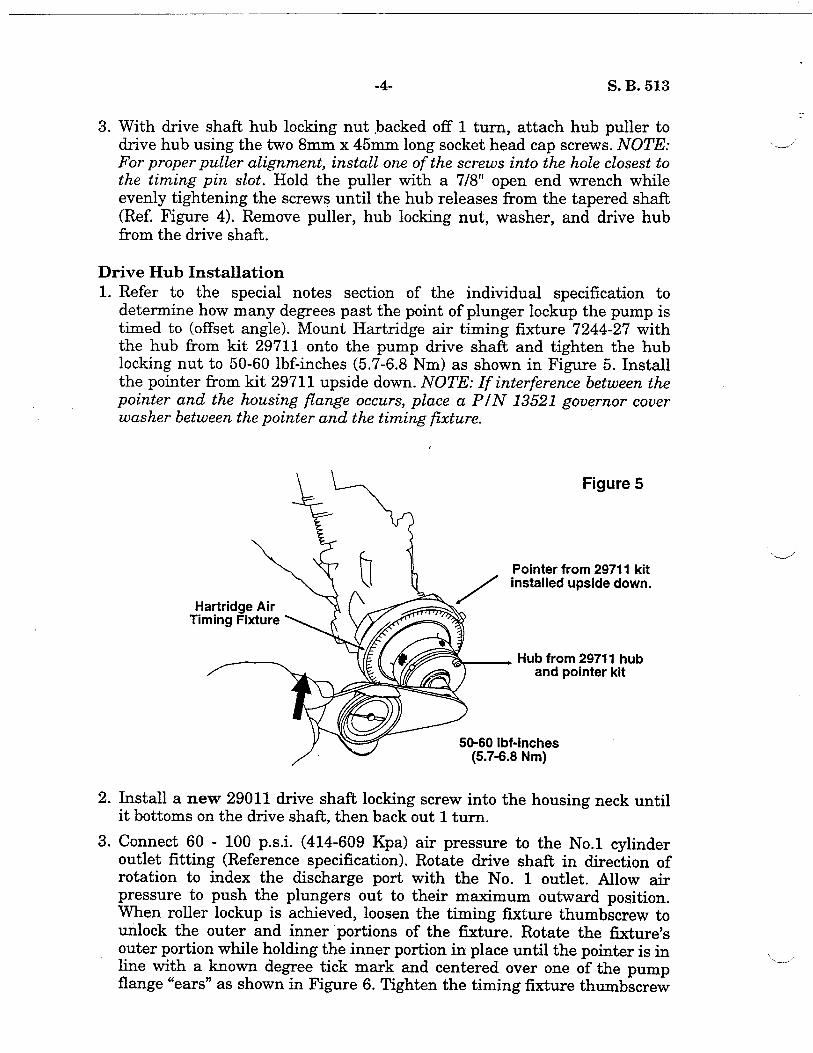
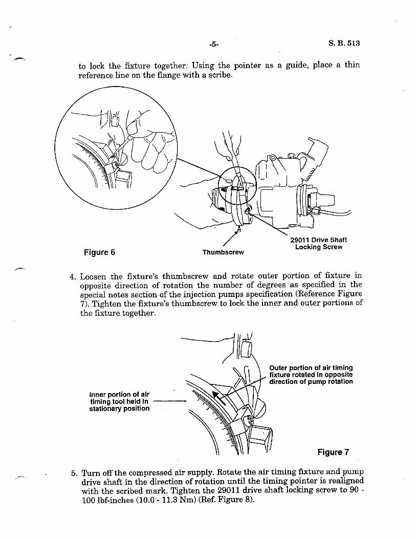
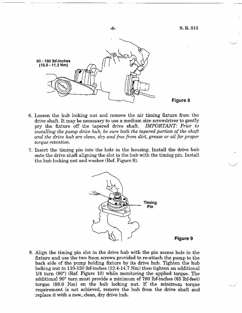
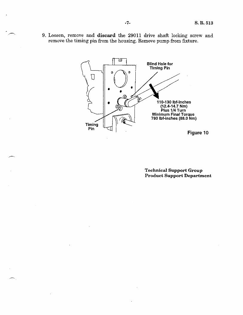


”
NO:: 520
SERVICE BULLET
SUBJECT: LOW SPEED FUEL IJlMlTER
As legislation continues to mandate decreases in diesel engine emissions, engine manufacturers find it necessary to more closely control fuel delivery and injection timing functions. Stanadyne plays a significant roll in this effort by developing special injection pump features such as the Low Speed Fuel Limiter. This new feature is designed to reduce wide-open throttle (WOT) fuel delivery below engine peak torque speed in order to control low speed black smoke and exhaust emissions. It is at speeds below peak torque speed (generally below 1600 ERPM) where there is insufficient air to burn the fuel normally injected. This is particularly true with turbocharged engines.
The Low Speed Fuel Limiter (LSFL) feature is located in the hydraulic head assembly and uses an adjustable orifice screw and a fuel limiter piston to restrict the flow of fuel to the metering valve at wide open throttle. Figures la and lb show the locations of the adjustable orifice screw and fuel limiter piston.
Adjustable Orifice Screw Fuel Limiter Fuel Limiter
Figure la Figure lb
Operation of the Low Speed Fuel Limiter
The adjustable orifice screw and the fuel limiter piston are located in passageways that feed fuel under transfer pump pressure to the pump’s
Diesel Systems Division, Stanadyne Automotive Corp. 9’2 Deerfield Road, Windsor, CT 06095, USA Tel: (860) 525.0821; Telex: 99218: Telecopy: (860) 525-4215
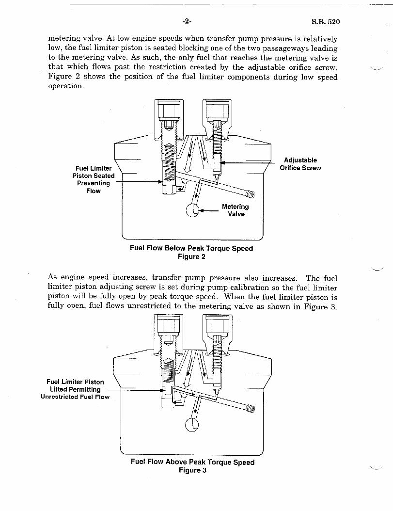
-2- S.B. 520
metering valve. At low engine speeds when transfer pump pressure is relatively low, the fuel limiter piston is seated blocking one of the two passageways leading to the metering valve. As such, the only fuel that reaches the metering valve is that which flows past the restriction created by the adjustable orifice screw. Figure 2 shows the position operation.
of the fuel limiter components during low speed
Fuel Limiter Piston Seated
Preventing Flow
Metering Valve
Adjustable Orifice Screw
L J
Fuel Flow Below Peak Torque Speed Figure 2
As engine speed increases, transfer pump pressure also increases. The fuel limiter piston adjusting screw is set during pump calibration so the fuel limiter piston will be fully open by peak torque speed. When the fuel limiter piston is
fullv onen, fuel flows unrestricted to the metering valve as shown in PimIre .?
Fuel Limiter Piston Lifted Permitting
Unrestricted Fuel Flow
Fuel Flow Above Peak Torque Speed Figure 3

-3- S.B. 520 //
t--
Maximum (wide-open throttle) fuel delivery from peak torque speed to rated speed is then controlled by the roller to roller dimension (leaf springs) as is the case with non-fuel limiter pumps.,
Figure 4
WOT Fuel Delivery Curves Low Speed Fuel Limiter vs. Baseline
100 ~~ ~. ___~~ .~______..~~
5’ 85 z 80 ;g 75 ;E_ 70
65
---O-Fuel Limiter _ _._~~~ ..-
--O-Non-Fuel Limiter a-
60 ! I I I I I I I I I I
200 600 1000 1400 1800 2200
Engine RPM
Figure 4 compares the wide open throttle (WOT) fuel curves of a non-fuel limiter pump to a pump with the low speed fuel limiter feature. The orifice screw setting determines how much WOT fuel is .trimmed back while the fuel limiter Ipiston adjusting screw setting determines when the fuel delivery curve returns to the normal fuel curve.
Servicing the Low Speed Fuel Limiter Feature
The serviceable components and torque specifications for the low speed fuel limiter are shown below in Figure 5.
Adjusting Screw Locknut 80-90 Ibf-inches
Fuel Limiter (9.0-l 0.1 Nom)
25-30 Ibf.-inches
Figure 5

-4- S.B. 520
Fuel Limiter Adjustments Whenever disassembly or calibration of a pump with the LSFL feature is required, the Welch plugs will have to be removed in order to disassemble and inspect the LSFL components and ‘to adjust the fuel limiter settings during pump calibration.
I .___’
Welch Plug
Figure 6
To remove the Welch plugs, position a l/S” punch (or equivalent) in the center of the Welch plug and carefully strike the punch with a hammer until the punch pierces the Welch plug. NOTE: Use care to avoid damaging the adjustable orifice screw and fuel limiter piston adjusting screw. Once the Welch plug is pierced, use a prying motion to remove the plugs from the locknuts as shown in Figure 6.
A fuel limiter adjusting wrench, P/N 33195, is required to make fuel limiter adjustments during pump calibration. To adjust the fuel limiter, insert the 33195 tool into the locknuts and loosen the locknuts with a 3/8” wrench. While holding the locknuts in place with the 3/8” wrench, use a l/8” hex key to set the adjustable orifice screw. Use a 5/32” hex key to set the fuel limiter piston adjusting screw as shown in figure 7. Refer to the individual specification for preliminary settings and the correct calibration sequence.
Fuel Limiter Adjustment
Figure 7
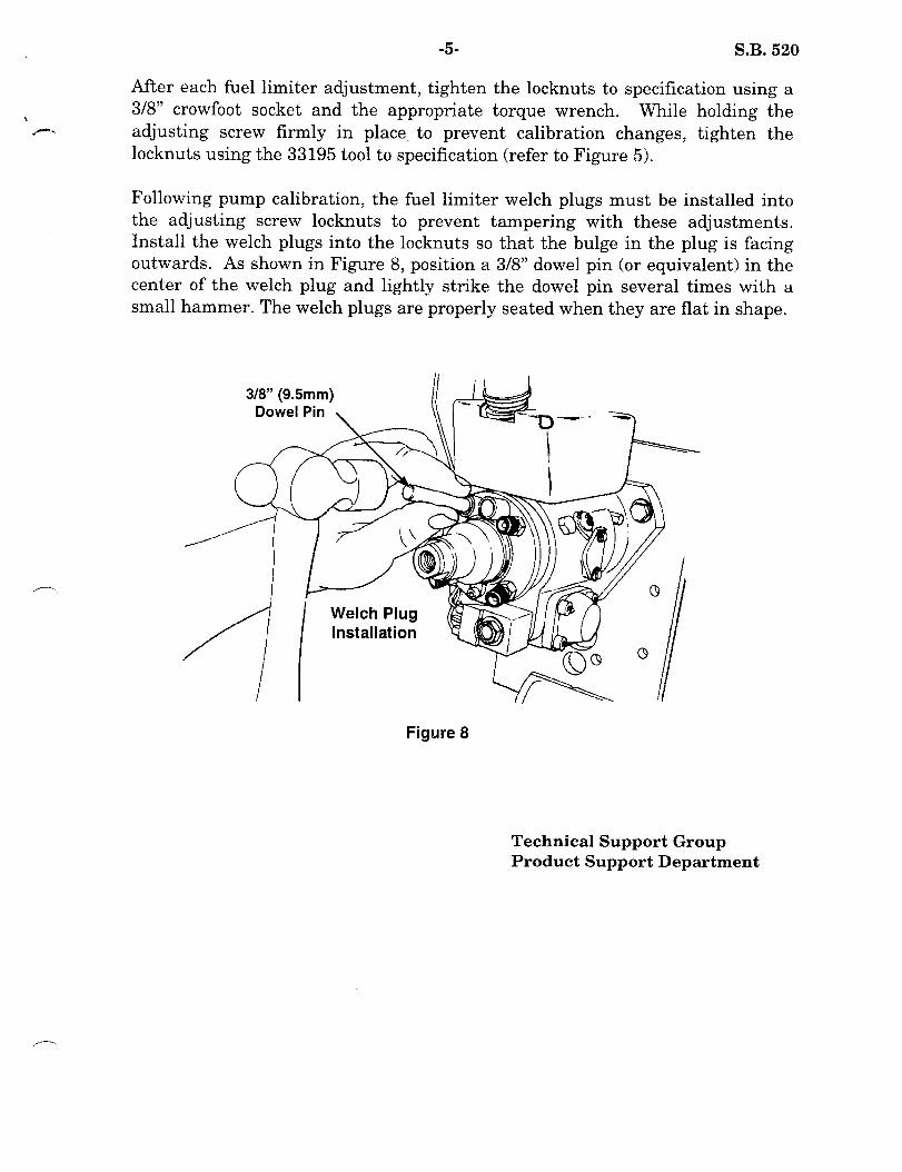
-5- S.B. 520
After each fuel limiter adjustment, tighten the locknuts to specification using a
L 3/8” crowfoot socket and the appropriate torque wrench. While holding the ,r*‘, adjusting screw firmly in place, to prevent calibration changes, tighten the
locknuts using the 33195 tool to specification (refer to Figure 5).
Following pump calibration, the fuel limiter Welch plugs must be installed into the adjusting screw locknuts to prevent tampering with these adjustments. Install the Welch plugs into the locknuts so that the bulge in the plug is facing outwards. As shown in Figure 8, position a 3/8” dowel pin (or equivalent) in the center of the Welch plug and lightly strike the dowel pin several times with a small hammer. The Welch plugs are properly seated when they are flat in shape.
3/W’ (9.5mm)
Figure 8
Technical Support Group Product Support Departme:nt


DATE: April 23, 2003 SERVICE BULLETIN
NO: 546
Stanadyne Corporation 92 Deerfield Road, Windsor, CT 06095, U.S.A. Tel: (860) 525-0821; Fax: (860) 683-4581; www.stanadyne.com
SUBJECT: DISCOLORATION OF CAM ROLLERS (P/N 11141)
It has been brought to our attention that some pumps have experienced discoloration of the cam rollers. After careful analysis, Stanadyne has determined that this discoloration is most likely caused by high surface temperatures due to friction from low lubricity fuel use. The cam rollers analyzed by Stanadyne met all dimensional and surface finish requirements, even though the surface is blue-black in color as shown in Figure 1. Therefore, Stanadyne has determined that discolored cam rollers may continue to be used without effecting pump performance or durability. Service Should you find discolored cam rollers during normal pump repair, inspect the rollers and cam follower shoes for signs of excessive abrasion. If the surface finish appears to be smooth without excessive scoring, reuse of the discolored rollers is acceptable. Since discoloration of cam rollers is a sign of low lubricity fuel usage, you should inform your customer of the benefits of using a lubricity additive such as Stanadyne’s Performance Formula®.
Technical Support Group Product Support Department
Discolored Normal
Figure 1

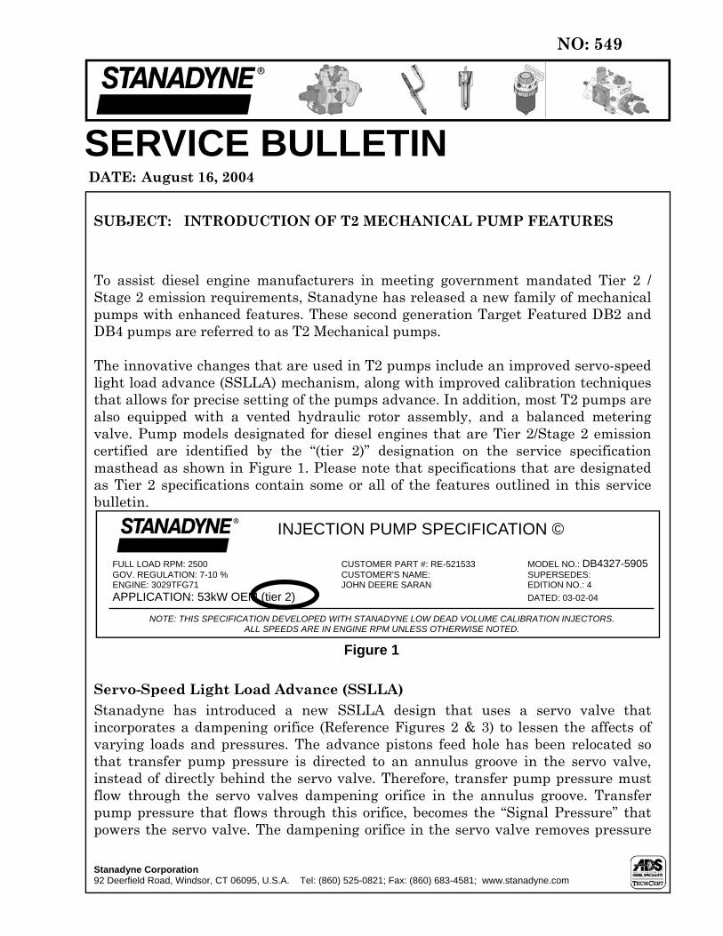
To assist diesel engine manufacturers in meeting government mandated Tier 2 / Stage 2 emission requirements, Stanadyne has released a new family of mechanical pumps with enhanced features. These second generation Target Featured DB2 and DB4 pumps are referred to as T2 Mechanical pumps. The innovative changes that are used in T2 pumps include an improved servo-speed light load advance (SSLLA) mechanism, along with improved calibration techniques that allows for precise setting of the pumps advance. In addition, most T2 pumps are also equipped with a vented hydraulic rotor assembly, and a balanced metering valve. Pump models designated for diesel engines that are Tier 2/Stage 2 emission certified are identified by the “(tier 2)” designation on the service specification masthead as shown in Figure 1. Please note that specifications that are designated as Tier 2 specifications contain some or all of the features outlined in this service bulletin.
Servo-Speed Light Load Advance (SSLLA) Stanadyne has introduced a new SSLLA design that uses a servo valve that incorporates a dampening orifice (Reference Figures 2 & 3) to lessen the affects of varying loads and pressures. The advance pistons feed hole has been relocated so that transfer pump pressure is directed to an annulus groove in the servo valve, instead of directly behind the servo valve. Therefore, transfer pump pressure must flow through the servo valves dampening orifice in the annulus groove. Transfer pump pressure that flows through this orifice, becomes the “Signal Pressure” that powers the servo valve. The dampening orifice in the servo valve removes pressure
DATE: August 16, 2004
SERVICE BULLETIN
NO: 549
Stanadyne Corporation 92 Deerfield Road, Windsor, CT 06095, U.S.A. Tel: (860) 525-0821; Fax: (860) 683-4581; www.stanadyne.com
SUBJECT: INTRODUCTION OF T2 MECHANICAL PUMP FEATURES
INJECTION PUMP SPECIFICATION ©
FULL LOAD RPM: 2500 CUSTOMER PART #: RE-521533 MODEL NO.: DB4327-5905 GOV. REGULATION: 7-10 % CUSTOMER'S NAME: SUPERSEDES: ENGINE: 3029TFG71 JOHN DEERE SARAN EDITION NO.: 4
APPLICATION: 53kW OEM (tier 2) DATED: 03-02-04
NOTE: THIS SPECIFICATION DEVELOPED WITH STANADYNE LOW DEAD VOLUME CALIBRATION INJECTORS. ALL SPEEDS ARE IN ENGINE RPM UNLESS OTHERWISE NOTED.
Figure 1
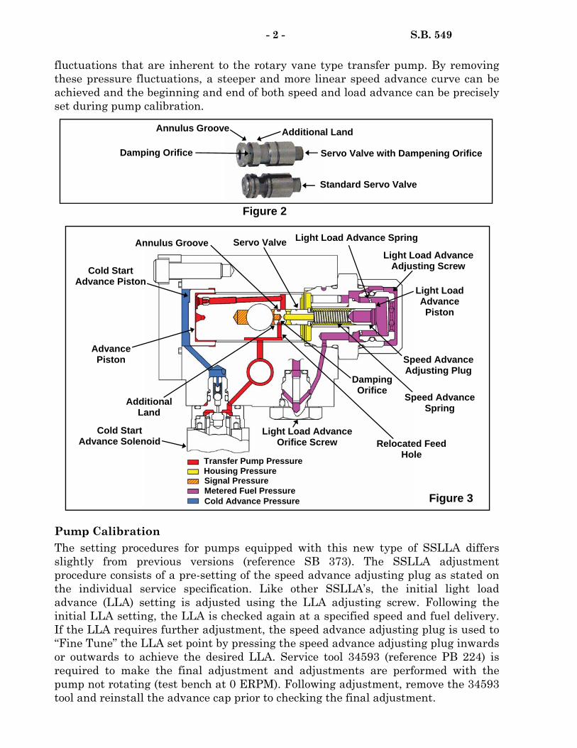
fluctuations that are inherent to the rotary vane type transfer pump. By removing these pressure fluctuations, a steeper and more linear speed advance curve can be achieved and the beginning and end of both speed and load advance can be precisely set during pump calibration.
Pump Calibration The setting procedures for pumps equipped with this new type of SSLLA differs slightly from previous versions (reference SB 373). The SSLLA adjustment procedure consists of a pre-setting of the speed advance adjusting plug as stated on the individual service specification. Like other SSLLA’s, the initial light load advance (LLA) setting is adjusted using the LLA adjusting screw. Following the initial LLA setting, the LLA is checked again at a specified speed and fuel delivery. If the LLA requires further adjustment, the speed advance adjusting plug is used to “Fine Tune” the LLA set point by pressing the speed advance adjusting plug inwards or outwards to achieve the desired LLA. Service tool 34593 (reference PB 224) is required to make the final adjustment and adjustments are performed with the pump not rotating (test bench at 0 ERPM). Following adjustment, remove the 34593 tool and reinstall the advance cap prior to checking the final adjustment.
- 2 - S.B. 549
Cold Start Advance Piston
Annulus Groove Servo Valve Light Load Advance Spring
Light Load Advance Adjusting Screw
Cold Start Advance Solenoid
Advance Piston
Relocated Feed Hole
Damping Orifice
Speed Advance Adjusting Plug
Speed Advance Spring
Light Load Advance Piston
Additional Land
Housing Pressure
Metered Fuel Pressure Cold Advance Pressure
Signal Pressure
Transfer Pump Pressure
Light Load Advance Orifice Screw
Figure 2
Standard Servo Valve
Damping Orifice
Annulus Groove Additional Land
Servo Valve with Dampening Orifice
Figure 3

- 3 - S.B. 549
Calibrating Injectors Stanadyne has introduced a new Calibrating Injector that is required to calibrate most T2 pumps, and also some recently released non T2 pumps. These calibrating injectors are a low dead volume type that are set at 207 bar (3000 psi) nozzle opening pressure, and are similar to the ISO 14681 standard. Stanadyne’s part number for these calibrating injector is 36950. All authorized Stanadyne service dealers must use Stanadyne Calibrating Injectors, P/N 36950, when servicing pumps that call for this part number on the individual service specification (Reference Service Letter 319). Stanadyne has found that the use of these Calibrating Injectors greatly enhances repeatability and calibration consistency. Hydraulic Rotor Assembly A new vent slot has been incorporated into the hydraulic rotor to reduce fluctuations in metered fuel pressure to the SSLLA circuit. The single vent slot is larger and in a different location (See Figure 4) than the two smaller vent slots traditionally used on D series rotors. This vent slot indexes with the charging ports in the hydraulic head assembly between charging events, venting any fluctuation in metered fuel pressure back to housing pressure. The vented rotor provides for a more linear advance curve (especially on 3 cylinder applications) and also provides for better light load advance consistency on pumps that are equipped with the low speed fuel limiter feature. Metering Valve Most T2 pumps use a balanced metering valve as shown in Figure 5, which reduces side loading of the valve. This feature allows for increased consistency of metered fuel pressure by attenuating pressure fluctuations caused by metering valve positioning resulting in additional low idle advance and improves low idle stability.
Technical Support Group Product Support Department
Vent Slot
Figure 4
Balance Hole
Balanced Metering
Valve
Standard Metering
Valve
Figure 5


DATE: October 15, 2005
SERVICE BULLETIN
NO: 553
Stanadyne Corporation 92 Deerfield Road, Windsor, CT 06095, U.S.A. Tel: (860) 525-0821; Fax: (860) 683-4581; www.stanadyne.com
SUBJECT: STATIC TIMING PIN FEATURE
Several of Stanadyne’s engine manufacturing customers have requested a more precise static timing method when installing fuel injection pumps to their engines. In order to meet this requirement, Stanadyne has released a number of T2 featured pump models (Reference S.B. 549) which are dynamically lock shaft timed during pump production. A static timing pin design has also been incorporated into these pump models to maintain the accuracy of dynamic timing in cases where the drive shaft lock is disengaged (Reference S.B. 460) and the correct lock shaft timing angle needs to be re-established. The timing pin design consists of a slotted rotor hub, timing lock plate, and a removable timing pin (P/N 37588) as shown in Figure 1. Once the dynamic timing angle is obtained during factory testing the drive shaft is locked, the timing pin is then indexed in the rotor hub slot and the timing lock plate is tightened in position. Due to the accuracy of factory dynamic pump timing, the timing lock plate should not be removed nor should the position of the timing lock plate be disturbed unless absolutely necessary. The 37588 timing pin is considered a mandatory auditable service tool (Reference Section 2.7.2 of the 99666 Stanadyne Policies and Procedures Manual ).
Service In most cases, the pump may be serviced without removing or altering the position of the timing lock plate. However, certain service scenarios do require timing lock plate removal. In these cases, choose the following service scenario that best fits the appropriate level of pump service being performed (Reference Figure 2).
Figure 1
Timing Pin (P/N 37588)
Timing Lock Plate
Slot in Hydraulic Rotor Hub

- 2 - S.B. 553
Scenario 1 - This procedure is used when removal of the timing lock plate is required and no major components have been changed or the roller to roller settings altered (i.e. for timing lock plate gasket replacement). This procedure involves indexing the timing pin in the rotor hub slot then locking the drive shaft in the factory established position.
1. Remove the timing lock plate plug (5/32” Hex Bit, P/N 13336 or equivalent) in the center of the timing lock plate and insert a 37588 timing pin .
2. Rotate the drive shaft until the pin indexes with the slot in the hydraulic rotor hub (Reference Figure 1) and lock the drive shaft as outlined in Service Bulletin 460.
3. Remove the two timing lock plate mounting screws (T15 Tamper Proof), the timing lock plate, and the gasket. Clean the mating surfaces.
4. Install the timing lock plate, new gasket, and both mounting screws. Index the timing pin in the rotor hub slot and tighten the two timing lock plate mounting screws to 15-20 lbf.-inches (1.7-2.3 N•m).
5. Remove the timing pin and install timing lock plate plug, tighten to 20-30 lbf.-inches (2.3-3.4 N•m).
Scenario 2 - This procedure is used when a major component or adjustment that directly affects pump static timing has been changed (head & rotor, housing, advance piston, drive shaft or roller to roller settings). For these cases, the pump must be air timed to the housing (Reference S.B. 177) according the latest edition of the individual service specification.
1. Air time the pump according to the individual service specification and tighten the drive shaft locking screw to 105-110 lbf.-inches (11.8-12.4 N•m) (Reference S.B. 460).
2. Remove the timing lock plate plug (5/32” Hex Bit, P/N 13336 or equivalent) in the center of the timing lock plate and insert a 37588 timing pin.
3. Loosen, but do not remove, the two timing lock plate tamper resistant mounting screws (T15 Tamper Proof) .
Figure 2 Timing Pin (P/N 37588)
Timing Lock Plate Mounting Screws 15-20 lbf.-inches
(1.7-2.3 N•m) T15 Tamper Proof
Timing Lock Plate
Move Timing Lock Plate up or down to position Timing Pin in slot
on Rotor Hub
Timing Lock Plate Plug (not shown)
20-30 lbf.-inches (2.3-3.4 N•m)
5/32” Hex Bit, P/N 13336

4. Move the timing lock plate up or down until the pin indexes with the slot in the hydraulic rotor hub (Reference Figure 1).
5. Tighten the two timing lock plate mounting screws to 15-20 lbf.-inches (1.7-2.3 N•m).
6. Remove the timing pin and install timing lock plate plug, tighten to 20-30 lbf.-inches (2.3-3.4 N•m).
Technical Support Group Product Support Department
- 3 - S.B. 553


Stanadyne Corporation 92 Deerfield Road, Windsor, CT 06095, U.S.A. Tel: (860) 525-0821; Fax: (860) 683-4581; www.stanadyne.com
NO: 559 DATE: July 24, 2008
SERVICE BULLETIN
Many DB2 automotive pumps use a drive arrangement with three cup type seals, as
shown in Figure 1. Two of the seals are identical (P/N 10453) and are black in color.
One of the 10453 seals is used to prevent fuel from entering the engines crankcase
and the other is used to prevent engine oil from entering the pump. The third cup
seal (P/N 21860), is red in color and was designed specifically to prevent fuel leakage
during cold engine operation. This seal is positioned on the drive shaft in the seal
groove between the two black drive shaft seals.
The 21860 red drive shaft seals are made from a rigid material which is not as
elastic as the black drive shaft seals (P/N 10453). Because of this, special care must
be taken to prevent seal damage during pump assembly.
• Ensure the correct drive shaft seal assembly tool (P/N 22727) is being used.
NOTE: The O.D. of the stepped shank on a DB/DC drive shaft seal assembly
tool (P/N 13369) is too large and may damage the 21860 red drive shaft seal if
mistakenly used during assembly.
• Closely inspect the 22727 drive shaft assembly tool for any signs of surface
irregularities (nicks, burrs, raised scratches, etc.). Repair or replace the
assembly tool as required.
• Use SAE 30W engine oil to generously lubricate the cup seals and the drive
shaft seal assembly tool. In the past, the use of assembly lubricant (P/N 22204)
was recommended for drive shaft cup seal assembly. However, recent testing
has shown that by using engine oil the probability of damaging the 21860 drive
shaft seal during assembly is significantly reduced.
Technical Support Group
Product Support Department
SUBJECT: INSTALLATION OF DRIVE SHAFT SEAL, P/N 21860
Figure 1
Typical DB2 Automotive
Drive Shaft Assembly
Drive Shaft Seal (Red) P/N 21860
Cold Temperature Fuel Seal
Drive Shaft Seal (Black) P/N 10453
Engine Oil Seal
Drive Shaft Seal (Black) P/N 10453 Fuel Seal
Seal Grooves


NO: 562 R1 DATE: October 2, 2009
SERVICE BULLETIN
Stanadyne Corporation 92 Deerfield Road, Windsor, CT 06095, U.S.A. Tel: (860) 525-0821; Fax: (860) 683-4581; www.stanadyne.com
Stanadyne’s innovative mechanical pump features assist engine manufacturers in
meeting emission certification requirements. Many of these features are designed for
accurate and repeatable fuel injection timing (Reference S.B.’s 373, 373A & 549).
Accordingly, the calibrating parameters for these pump models are very stringent
with timing tolerances of +/- 0.05 engine degree. To assure our OEM customers that
these exacting standards are maintained following pump repair, Stanadyne has
developed an electronic advance indicator (Figure 1) for close tolerance calibration of
“D” Series mechanical rotary pumps.
The contents of the 39938 Electronic Advance Indicator kit are shown in Figure 1.
As a result of the accuracy of the 39938 Electronic Advance Indicator, it is
considered a required tool that supersedes the 23745 mechanical advance indicator
for testing DB2, DB4 and DM pump models.
SUBJECT: ELECTRONIC ADVANCE INDICATOR (EAI) FOR
STANADYNE “D” SERIES FUEL INJECTION PUMPS
SUPERSEDES: S.B. 562 dated 04/02/09
Figure 1
Gasket (P/N 22831)
Spacer (P/N 39965)
Gasket (P/N 13367)
Power Supply (P/N 39943)
O-ring Seal not shown (P/N 27607)
Wiring Harness (P/N 39942)
Cam Movement Sensor Assembly (P/N 39939)
Plug, Housing Pressure Port (P/N 21735)
O-ring Seal not shown (P/N 27607)
Cam Pointer & Spring Assembly
(P/N 39957)
Mounting Screws (2) (P/N 39952)
15-20 lbf.-in (1.5-2.5 N•m)
Magnetic Mounting Pad (P/N 39943)
EAI Monitor (P/N 39940)
Housing Pressure Fitting (P/N 22035)
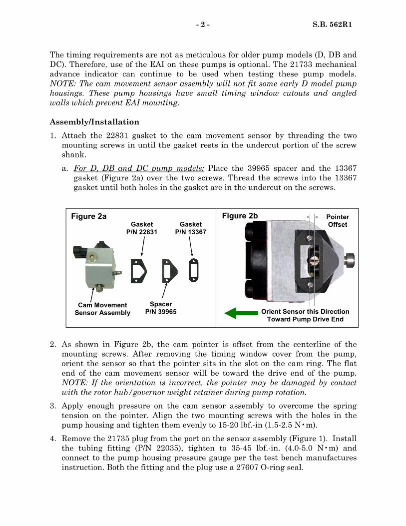
- 2 - S.B. 562R1
The timing requirements are not as meticulous for older pump models (D, DB and
DC). Therefore, use of the EAI on these pumps is optional. The 21733 mechanical
advance indicator can continue to be used when testing these pump models.
NOTE: The cam movement sensor assembly will not fit some early D model pump
housings. These pump housings have small timing window cutouts and angled
walls which prevent EAI mounting.
Assembly/Installation
1. Attach the 22831 gasket to the cam movement sensor by threading the two
mounting screws in until the gasket rests in the undercut portion of the screw
shank.
a. For D, DB and DC pump models: Place the 39965 spacer and the 13367
gasket (Figure 2a) over the two screws. Thread the screws into the 13367
gasket until both holes in the gasket are in the undercut on the screws.
2. As shown in Figure 2b, the cam pointer is offset from the centerline of the
mounting screws. After removing the timing window cover from the pump,
orient the sensor so that the pointer sits in the slot on the cam ring. The flat
end of the cam movement sensor will be toward the drive end of the pump.
NOTE: If the orientation is incorrect, the pointer may be damaged by contact
with the rotor hub/governor weight retainer during pump rotation.
3. Apply enough pressure on the cam sensor assembly to overcome the spring
tension on the pointer. Align the two mounting screws with the holes in the
pump housing and tighten them evenly to 15-20 lbf.-in (1.5-2.5 N•m).
4. Remove the 21735 plug from the port on the sensor assembly (Figure 1). Install
the tubing fitting (P/N 22035), tighten to 35-45 lbf.-in. (4.0-5.0 N•m) and
connect to the pump housing pressure gauge per the test bench manufactures
instruction. Both the fitting and the plug use a 27607 O-ring seal.
Figure 2a
Cam Movement Sensor Assembly
Gasket P/N 13367
Gasket P/N 22831
Spacer P/N 39965
Pointer Offset
Orient Sensor this Direction Toward Pump Drive End
Figure 2b
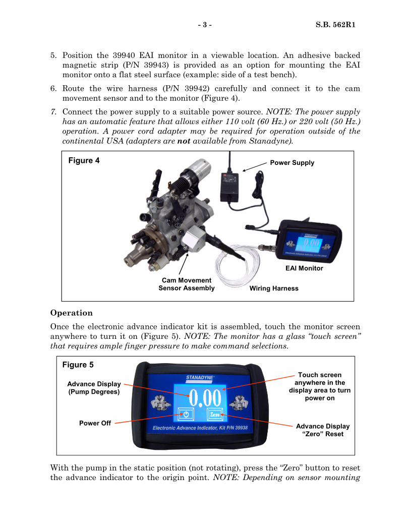
5. Position the 39940 EAI monitor in a viewable location. An adhesive backed
magnetic strip (P/N 39943) is provided as an option for mounting the EAI
monitor onto a flat steel surface (example: side of a test bench).
6. Route the wire harness (P/N 39942) carefully and connect it to the cam
movement sensor and to the monitor (Figure 4).
7. Connect the power supply to a suitable power source. NOTE: The power supply
has an automatic feature that allows either 110 volt (60 Hz.) or 220 volt (50 Hz.)
operation. A power cord adapter may be required for operation outside of the
continental USA (adapters are not available from Stanadyne).
- 3 - S.B. 562R1
Operation
Once the electronic advance indicator kit is assembled, touch the monitor screen
anywhere to turn it on (Figure 5). NOTE: The monitor has a glass “touch screen”
that requires ample finger pressure to make command selections.
Figure 5
Advance Display (Pump Degrees)
Power Off Advance Display “Zero” Reset
Touch screen anywhere in the
display area to turn power on
EAI Monitor
Cam Movement Sensor Assembly Wiring Harness
Power Supply Figure 4
With the pump in the static position (not rotating), press the “Zero” button to reset
the advance indicator to the origin point. NOTE: Depending on sensor mounting

- 4 - S.B. 562R1
Date Revision Description
10/09 1 Added information about operation, mounting, housing
pressure port and warranty
orientation and pump rotation the display may read negative (-). Additionally, due
to the sensitivity of the sensor the display may fluctuate +/- 0.02 degrees. Once the
pump is operating at sufficient speed, sensor fluctuations will be eliminated. To
turn the monitor off, simply press the “Power Off” screen button ( Figure 5 ).
Warranty
Each serviceable component within the 39938 Electronic Advance Indicator kit is
covered by a one year limited warranty for defects in material and workmanship. If
a serviceable component were to fail, submit a warranty claim only for the specific
component not the entire kit. Likewise, when replacing the suspect component
only order that component not the entire kit. As with all service tools, the failed
component must be returned to:
Stanadyne Corporation
92 Deerfield Road
Windsor, CT 06095
Attention: Warranty Return Dept.
Consult section 4.6.4 of the Stanadyne Policies and Procedures Manual (99966)
found on the Stanadyne service website for warrantable conditions pertaining to
service tools.
Technical Support Group
Product Support Department

Stanadyne Corporation 92 Deerfield Road, Windsor, CT 06095, U.S.A. Tel: (860) 525-0821; Fax: (860) 683-4581; www.stanadyne.com
NO: 563 DATE: July 15, 2009
SERVICE BULLETIN
SUBJECT: ADVANCE PISTON CHANGES FOR SERVO-SPEED LIGHT
LOAD ADVANCE (SSLLA)
The SSLLA design for Target featured DB2 and DB4 pump models has undergone
many changes since its introduction (Reference S.B. 373). Two of the more
significant changes include the introduction of non-plated advance pistons with
sleeved advance bore pump housings and the separation of the advance piston power
side design types.
Plated vs. Non-Plated Advance Pistons
The aluminum advance bore in the pump housing was originally sized to fit a plated
advance piston. In an effort to simplify pump service, by avoiding the need for
multiple oversized advance pistons and housing bore reamers, Stanadyne introduced
steel sleeved advance bore pump housings and non-plated pistons. This design
enhancement shifts the major wear component in the advance area from the
aluminum housing bore to a non-plated steel advance piston, which improves
advance consistency and pump longevity
Advance Piston Types
The original advance piston design included provisions for both a reed valve and an
orifice screw. For manufacturing purposes, the advance pistons have been separated
into two types: a reed valve type and a orifice screw type (Figure 1).
Current Non-Plated SSLLA Piston Types Plated and Early Non-Plated
SSLLA Pistons Reed Valve Orifice Screw
Non-Threaded Hole
Threaded Hole for Reed Valve Screw
Reed Valve Slot
Threaded Hole for Orifice Screw
Threaded Hole for Orifice Screw
Figure 1
Part Number Locations
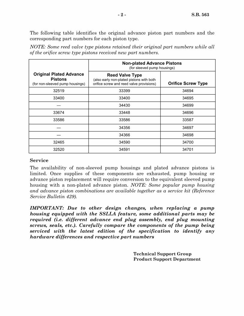
- 2 - S.B. 563
The following table identifies the original advance piston part numbers and the
corresponding part numbers for each piston type.
NOTE: Some reed valve type pistons retained their original part numbers while all
of the orifice screw type pistons received new part numbers.
Service
The availability of non-sleeved pump housings and plated advance pistons is
limited. Once supplies of these components are exhausted, pump housing or
advance piston replacement will require conversion to the equivalent sleeved pump
housing with a non-plated advance piston. NOTE: Some popular pump housing
and advance piston combinations are available together as a service kit (Reference
Service Bulletin 429).
IMPORTANT: Due to other design changes, when replacing a pump
housing equipped with the SSLLA feature, some additional parts may be
required (i.e. different advance end plug assembly, end plug mounting
screws, seals, etc.). Carefully compare the components of the pump being
serviced with the latest edition of the specification to identify any
hardware differences and respective part numbers
Technical Support Group
Product Support Department
Non-plated Advance Pistons (for sleeved pump housings)
Reed Valve Type (also early non-plated pistons with both orifice screw and reed valve provisions) Orifice Screw Type
32519 33399 34694
33400 33400 34695
— 34430 34699
33674 33448 34696
33586 33586 33587
— 34356 34697
— 34366 34698
32465 34590 34700
32520 34591 34701
Original Plated Advance Pistons
(for non-sleeved pump housings)
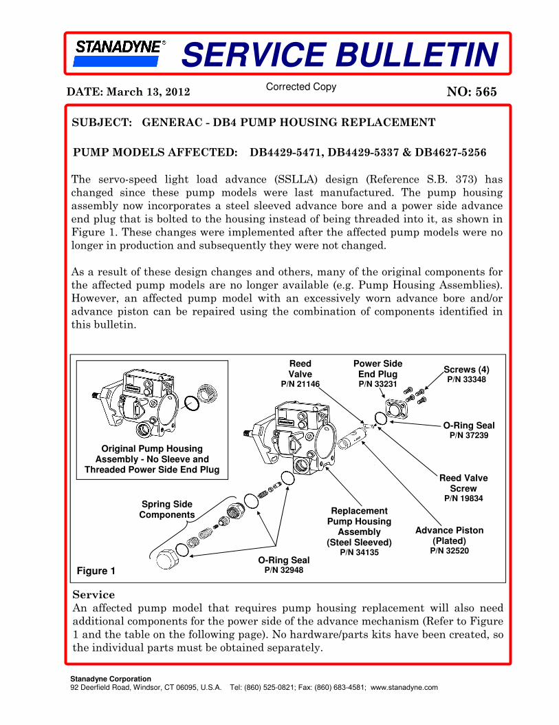
Stanadyne Corporation 92 Deerfield Road, Windsor, CT 06095, U.S.A. Tel: (860) 525-0821; Fax: (860) 683-4581; www.stanadyne.com
NO: 565 DATE: March 13, 2012
SERVICE BULLETIN
SUBJECT: GENERAC - DB4 PUMP HOUSING REPLACEMENT
PUMP MODELS AFFECTED: DB4429-5471, DB4429-5337 & DB4627-5256
Service
An affected pump model that requires pump housing replacement will also need
additional components for the power side of the advance mechanism (Refer to Figure
1 and the table on the following page). No hardware/parts kits have been created, so
the individual parts must be obtained separately.
Figure 1
Screws (4) P/N 33348
O-Ring Seal P/N 37239
Power Side End Plug P/N 33231
Advance Piston (Plated)
P/N 32520
Reed Valve
P/N 21146
Reed Valve Screw
P/N 19834
Replacement Pump Housing
Assembly (Steel Sleeved)
P/N 34135
Original Pump Housing Assembly - No Sleeve and
Threaded Power Side End Plug
O-Ring Seal P/N 32948
Spring Side Components
The servo-speed light load advance (SSLLA) design (Reference S.B. 373) has
changed since these pump models were last manufactured. The pump housing
assembly now incorporates a steel sleeved advance bore and a power side advance
end plug that is bolted to the housing instead of being threaded into it, as shown in
Figure 1. These changes were implemented after the affected pump models were no
longer in production and subsequently they were not changed.
As a result of these design changes and others, many of the original components for
the affected pump models are no longer available (e.g. Pump Housing Assemblies).
However, an affected pump model with an excessively worn advance bore and/or
advance piston can be repaired using the combination of components identified in
this bulletin.
Corrected Copy
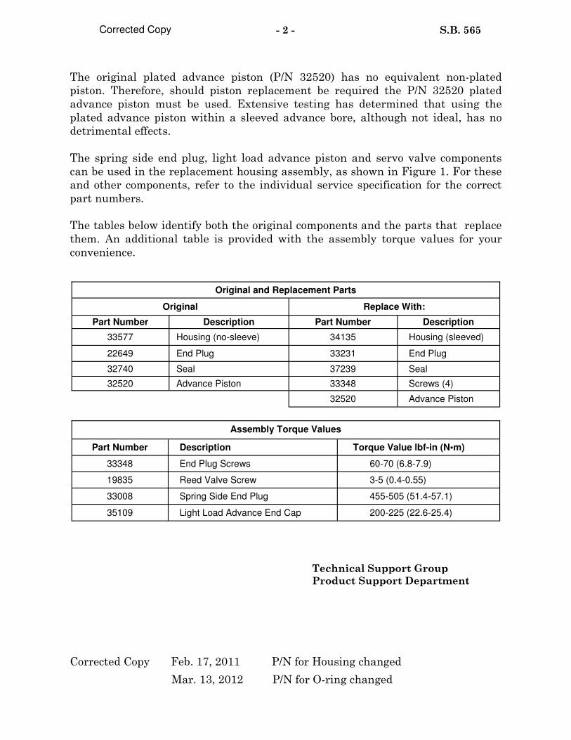
- 2 - S.B. 565
The original plated advance piston (P/N 32520) has no equivalent non-plated
piston. Therefore, should piston replacement be required the P/N 32520 plated
advance piston must be used. Extensive testing has determined that using the
plated advance piston within a sleeved advance bore, although not ideal, has no
detrimental effects.
The spring side end plug, light load advance piston and servo valve components
can be used in the replacement housing assembly, as shown in Figure 1. For these
and other components, refer to the individual service specification for the correct
part numbers.
The tables below identify both the original components and the parts that replace
them. An additional table is provided with the assembly torque values for your
convenience.
Original Replace With:
Part Number Description Part Number Description
33577 Housing (no-sleeve) 34135 Housing (sleeved)
22649 End Plug 33231 End Plug
32740 Seal 37239 Seal
32520 Advance Piston 33348 Screws (4)
32520 Advance Piston
Original and Replacement Parts
Part Number Description Torque Value lbf-in (N•m)
33348 End Plug Screws 60-70 (6.8-7.9)
19835 Reed Valve Screw 3-5 (0.4-0.55)
Assembly Torque Values
33008 Spring Side End Plug 455-505 (51.4-57.1)
35109 Light Load Advance End Cap 200-225 (22.6-25.4)
Technical Support Group
Product Support Department
Corrected Copy
Corrected Copy Feb. 17, 2011 P/N for Housing changed
Mar. 13, 2012 P/N for O-ring changed

Stanadyne Corporation 92 Deerfield Road, Windsor, CT 06095, U.S.A. Tel: (860) 525-0821; Fax: (860) 683-4581; www.stanadyne.com
NO: 567 DATE: November 14, 2011
SERVICE BULLETIN
Inadequate delivery valve stop screw thread depth in the hydraulic rotor assemblies
used in a small number of the affected pump models has caused low fuel delivery
during initial pump calibration. Without the full thread depth the stop screw does
not seat the delivery valve stop when tightened, causing delivery valve stop seat
leakage (Reference S.B. 143B). To prevent thread interference during assembly, a
special stepped delivery valve stop screw (Figure 1) has been introduced specifically
for use in these rotor assemblies.
Each pump manufactured with a 23124LT screw is identified by “SB567” stamped
on the nameplate in the location shown in Figure 2.
SUBJECT: HYDRAULIC ROTOR ASSEMBLIES WITH STEPPED
DELIVERY VALVE STOP SCREW
PUMP MODELS AFFECTED: DB2831-5079, 5149, 6201
Service
If delivery valve removal is required for one of the affected pumps, both the delivery
valve stop (P/N 26070) and the delivery valve stop screw (P/N 23124LT) must be
replaced. When ordering a stepped delivery valve stop screw, ensure the “LT” suffix
is included with the part number. The stop screw is installed in the orientation
shown in Figure 1 and tightened to 85-90 lbf.-in. (9.5-10 N•m).
Technical Support Group
Product Support Department
SB567
J1 DB2831-5079 3400
12345678 10224039 Nameplate
Stamped “SB567” in this Location
Figure 2
Standard Delivery Valve Stop Screw
P/N 23124
Stepped Delivery Valve Stop Screw
P/N 23124LT Figure 1
This End Goes Toward Delivery
Valve Stop


DATE: July 23, 2012
SERVICE BULLETIN
NO: 568
Stanadyne Corporation 92 Deerfield Road, Windsor, CT 06095, U.S.A. Tel: (860) 525-0821; Fax: (860) 683-4581; www.stanadyne.com
SUBJECT: CHANGES TO ADDRESS LOW POWER
Since the introduction of the above affected pump model, there have been some
reports of low power issues for engines fitted on HIDROMEK applications. To address
this low power issue, John Deere is requesting that the Roller to Roller (R-to-R) fuel
and/or Low Speed Fuel Limiter (LSFL) setting be reset to the “Following Pump
Service” section of the latest DB4-6189 pump specification (edition 4), if necessary.
Service
Should you receive a DB4-6189 pump with a complaint of low power, perform the
“Test As Received” (TAR) routine. If the pump meets all of the TAR check points but
if it is noted that the R-to-R check point at 1500 RPM (step 3g) is below 107 mm3,
and/or the LSFL check point at 1300 RPM (step 3h) is below 105 mm3, the pump must
be reset to the “Following Pump Service” routine of the specification. However, if the
pump meets all of the TAR check points and also meets these two OEM requested
check points (107 mm3 at step 3g and 105 mm3/st at step 3h), no further action is
required and the pump can be returned to the customer.
Warranty
If the pump met all of the TAR check points of the latest test specification but the fuel
did not meet the OEM calibration requirements as outlined above (1500 RPM - 107
mm3 minimum and/or 1300 RPM - 105 mm3 minimum), all costs associated to reset
the pump are chargeable to the customer because this request is being made by John
Deere.
For Pumps that were tested that did not meet other TAR checkpoints (not specified in
this Service Bulletin) and/or were found to be out of the following fuel flow ranges,
RPM Throttle Position mm3/stk.
1500 WOT 105.5 - 111
1300 WOT 98 - 114.5
a warranty claim may be submitted for reimbursement if the pump is within the
warranty period.
Technical Support Group
Product Support Department
LIMITED DISTRIBUTION
PUMP MODELS AFFECTED: DB4429-6189 (RE-548320)
LIMITED DISTRIBUTION — JOHN DEERE


DATE: August 27, 2012
SERVICE BULLETIN
NO: 569
Stanadyne Corporation 92 Deerfield Road, Windsor, CT 06095, U.S.A. Tel: (860) 525-0821; Fax: (860) 683-4581; www.stanadyne.com
SUBJECT: LOW POWER, SMOKE, ROUGH RUNNING, STALLING
There has been a number of performance related issues with John Deere 5075E
Tractors in Brazil. The engine in those tractors was originally fitted with a DB4-5986
pump and the root cause of the performance issues are related to low engine RPM
recovery and premature wear of the pump’s transfer pump components (caused by fuel
with inadequate lubricity). As a result of the low RPM performance and premature
wear issues, John Deere has approved the release of a new pump model, DB4-6264
(RE-560216), to replace the DB4-5986 in Brazil only. The DB4-6264 is equipped with
Reduced Lubricity Fuel Components (RLFC) in the transfer pump area, a new cold
start advance piston with spring assist and a change in pump calibration.
Service
Should you receive a DB4-5986 pump for service with a complaint of low power,
smoke, rough running or stalling, the pump will need to be converted with the parts
listed in the table below and calibrated to the latest “Pump Following Service” routine
of the DB4-6264 Test Specification. Once the conversion is complete and the pump is
calibrated, the pump will need to be identified accordingly. The original nameplate
can be used for identification purposes as long as the original pump model number
and customer part number are etched out and the new model number (DB4327-6264)
and customer part number (RE-560216) are etched/stamped on the available field
spaces of the plate (Reference Figure 1). The other option is to install a new service
name plate, part number 36773, and transfer the serial number from the original
name plate onto it and etch/stamp the new pump model number and customer part
number accordingly.
LIMITED DISTRIBUTION
PUMP MODELS AFFECTED: DB4327-5986 (RE-531128)
LIMITED DISTRIBUTION — JOHN DEERE (BRAZIL ONLY)
Descripon Remove Install
Rotor Retainer, Transfer Pump 32859 33818
Rotor Retainer, Transfer Pump 19870 33817
Liner, Transfer Pump 21232 37447
Blade, Transfer Pump (Ref. S.B. 304) 34759 37267
Piston, Cold Advance 37236 34228
Cover, Power Side Advance 34805 39455
Spring, CSA Assist - 39454

2
Warranty
Since this request is being made by John Deere, all costs associated to convert the
pump are chargeable to the customer. Also, warranty claims should not be accepted
for pumps that are found to have failed due to normal and/or premature wear and tear
caused by fuel with inadequate lubricity. Technical Support Group
Product Support Department
F0 DB4327-5986
RE-531128 15531128 xxxxxxxx
xxxxxxxxxxxxxx
DB4327-6264
RE-560216
Figure 1
Etch out original model
number and customer
part number
Etch/Stamp new model
number and customer
part number