service bulletin no. sb-300-1-11 - extra aircraft · 300/sc, ea 300/lt and ea 300/lc aircraft...
TRANSCRIPT

EXTRA Flugzeugproduktions- Service Bulletin und Vertriebs-GmbH EA 300 EASA.21J.073 Safety Clamps on Garmin avionics units
Issue: A SB-300-1-11 Date: 18.07.11 Page: 1 of 11
SERVICE BULLETIN
No. SB-300-1-11
Extra considers compliance mandatory
Subject: Safety clamps on Garmin avionics units located in subpanels
Aircraft affected: EA 300 including models EA 300/S, EA 300/L, EA 300/200, EA 300/SC, EA 300/LT and EA 300/LC aircraft manufactured before July 2011 and equipped with optional Garmin avionics units (GNC 250XL, GTX 320, GTX 327, GTX 328, GTX 330, GNC 420[W], GNS 430[W], GNS 530[W]) within the instrument subpanel.
Purpose: It has been reported that a Garmin transponder GTX 328 slid out of its rack in a EA 300/L and jammed against the control stick while performing acrobatic maneuvers.
Figure 1: Slide out of units when not securely locked

EXTRA Flugzeugproduktions- Service Bulletin und Vertriebs-GmbH EA 300 EASA.21J.073 Safety Clamps on Garmin avionics units
Issue: A SB-300-1-11 Date: 18.07.11 Page: 2 of 11
Initial investigation showed that the front lobe of the locking mechanism was not in the full 90° vertical position to securely lock the unit in its rack. All above mentioned Garmin units feature the same locking mechanism.
Figure 2: Typ. locking device on Garmin installation rack
As an unsecured Garmin unit could result in a restricted pitch down control input, appropriate action has to be taken to make sure that the units located in the subpanel are always secure.
Safety clamps are introduced to prevent the units to slide out when the Garmin locking mechanism fails or is improperly used.
Approval: The technical content of this document is approved under the authority of DOA Nr. EASA.21J.073.
COMPLIANCE TIME
In case an alternative means of compliance with this service bulletin has been shown, no compliance time is given.
PART I: If no equivalent safety clamps are retrofitted so far, a repetitive inspection as described in PART I needs to be established as part of the preflight check until PART II of this Service Bulletin has been complied with.
PART II: A retrofit of a safety clamp as described in PART II needs to be carried out
• within the next 10h time-in-service (TIS) or • at the next 25h inspection, whichever occurs first
and
• whenever a unit will be (re-)installed.
EXTRA Flugzeugproduktions- Service Bulletin und Vertriebs-GmbH EA 300 EASA.21J.073 Safety Clamps on Garmin avionics units
Issue: A SB-300-1-11 Date: 18.07.11 Page: 3 of 11
PART I REPETITIVE INSPECTION
- Make sure that the Garmin avionics units rest against the back of their racks and that the front lobe of the locking mechanism of the units are fully engaged into their rack. This can be accomplished by => slightly grab each individual Garmin avionics unit at its face plate and gently try to pull out the unit of its rack and => looking at the bottom of the units, visually confirm that the locking lobe of each Garmin unit is in fully vertical position. To assist the visual inspection it is helpful to use a flashlight.
- In case a Garmin unit slides out of its rack, proceed with the instructions of PART II.
PART II RETROFIT
Note: Alterations or repair of the aircraft must be accomplished by licensed personnel only.
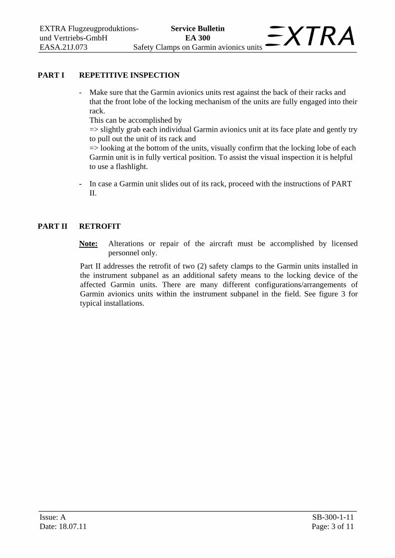
Part II addresses the retrofit of two (2) safety clamps to the Garmin units installed in the instrument subpanel as an additional safety means to the locking device of the affected Garmin units. There are many different configurations/arrangements of Garmin avionics units within the instrument subpanel in the field. See figure 3 for typical installations.
EXTRA Flugzeugproduktions- Service Bulletin und Vertriebs-GmbH EA 300 EASA.21J.073 Safety Clamps on Garmin avionics units
Issue: A SB-300-1-11 Date: 18.07.11 Page: 4 of 11
Figure 3: Typ. arrangements of Garmin avionics units within
the EA 300/L instrument subpanel
- Remove the Garmin units from their racks. Insert a 3/32-inch hex drive tool into the access hole on the unit face and rotate counter-clockwise until the mounting screw turns freely and the unit protrudes about 3/8 inch from the panel.
For installation of the nut plates in the appropriate place, it is recommended to remove the instrument subpanel.
a) For double seater variants/models:
- Remove canopy (as appropriate) per Chapter 53-00-01
- Remove rear instrument (as appropriate) panel cover 31-10-03
- Remove the front seat (as appropriate) per Chapter 25-15-01 (Removal of the instruments from upper instrument panel may be necessary)

EXTRA Flugzeugproduktions- Service Bulletin und Vertriebs-GmbH EA 300 EASA.21J.073 Safety Clamps on Garmin avionics units
Issue: A SB-300-1-11 Date: 18.07.11 Page: 5 of 11
- Disconnect wirings of electrical units located in the instrument subpanel (as required)
- Unscrew AN526 series attachment screws from the instrument subpanel and remove the subpanel in rearward direction to the pilots seat while the control stick is in the most LH or RH control input position (see figure 4). In some cases the LH and RH AN526 fuselage attachment screws of the instrument panel have to be unscrewed as well.
Figure 4: Attachment screws of the the instrument subpanel (EA 300/L shown)
b) For single seater variants/models:
- Remove canopy per Chapter 53-00-10
- Remove the engine cowling and main fuselage cover 51-00-01 (as appropriate)
- Disconnect wirings of electrical units located in the instrument subpanel (as required)
- Unscrew AN526 and DIN 933 attachment screws of the instrument subpanel and remove the subpanel in rearward direction to the pilots seat while the control stick is in the most LH or RH control input position (see figure 5). In some cases the

EXTRA Flugzeugproduktions- Service Bulletin und Vertriebs-GmbH EA 300 EASA.21J.073 Safety Clamps on Garmin avionics units
Issue: A SB-300-1-11 Date: 18.07.11 Page: 6 of 11
instrument panel also includes the subpanel (one part). This may require the removal of the instrument panel.
Figure 5: Attachment screws of the the instrument subpanel (EA 300/S shown)
The easiest way is to position one safety clamp in the center line on top and the second one below the units (see Figure 6.).
Figure 6: Position of safety clamps (EA 300/L shown)
If the configuration prevents this a RH and LH position or a combination is appropriate. Positions for the LH and RH are established by existing rivets (refer to Figure 7). Other positions may also be appropriate. The solid aluminum countersunk rivet positions can be easily recognized from the rear.

EXTRA Flugzeugproduktions- Service Bulletin und Vertriebs-GmbH EA 300 EASA.21J.073 Safety Clamps on Garmin avionics units
Issue: A SB-300-1-11 Date: 18.07.11 Page: 7 of 11
Figure 7: Alternative position of safety clamps (EA 300/L shown)
- For LH and RH positioned safety clamps: Remove the two (2) identified solid aluminum countersunk rivets.
- Drill needed holes for the nutplates used to attach the two (2) safety clamps at the appropriate locations.
EXTRA Flugzeugproduktions- Service Bulletin und Vertriebs-GmbH EA 300 EASA.21J.073 Safety Clamps on Garmin avionics units
Issue: A SB-300-1-11 Date: 18.07.11 Page: 8 of 11
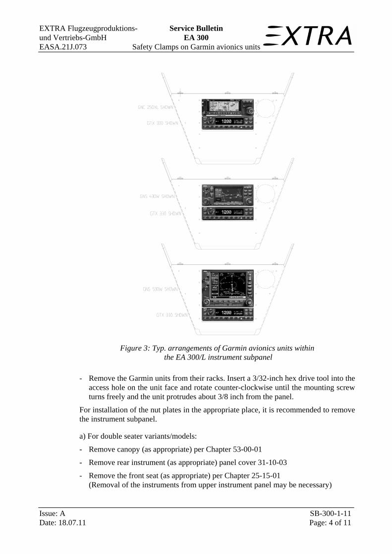
- Install the nutplates using solid aluminum countersunk or nut plate flush head rivets (refer to figure 8. and 9.).
Figure 8: Typical installation of safety clamps (top/bottom)

EXTRA Flugzeugproduktions- Service Bulletin und Vertriebs-GmbH EA 300 EASA.21J.073 Safety Clamps on Garmin avionics units
Issue: A SB-300-1-11 Date: 18.07.11 Page: 9 of 11
Figure 9: Typical installation of safety clamps (LH & RH)
- Reassemble the aircraft.
- Make appropriate logbook entry of compliance with PART II of this Service Bulletin.
EXTRA Flugzeugproduktions- Service Bulletin und Vertriebs-GmbH EA 300 EASA.21J.073 Safety Clamps on Garmin avionics units
Issue: A SB-300-1-11 Date: 18.07.11 Page: 10 of 11
MATERIAL
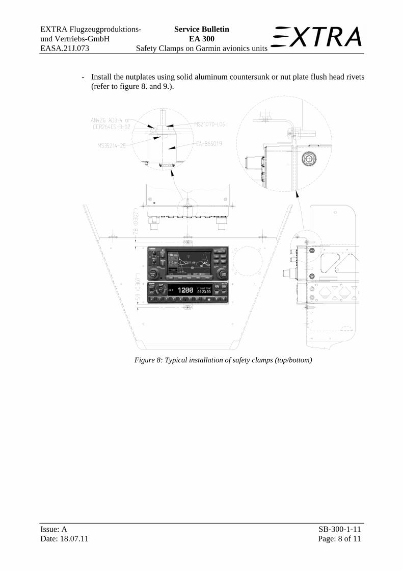
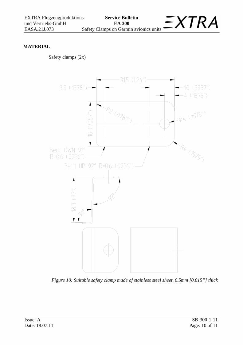
Safety clamps (2x)
Figure 10: Suitable safety clamp made of stainless steel sheet, 0.5mm [0.015”] thick

EXTRA Flugzeugproduktions- Service Bulletin und Vertriebs-GmbH EA 300 EASA.21J.073 Safety Clamps on Garmin avionics units
Issue: A SB-300-1-11 Date: 18.07.11 Page: 11 of 11
The material required for PART II may also be ordered from:
EXTRA Flugzeugproduktions- und Vertriebs GmbH Flugplatz Dinslaken Schwarze Heide 21 46569 Hünxe / Germany
Order retrofit kit including following items:
Kit No.: SB111A-1 (PN EA-86501.9-PG)
Eligible for: EA 300 and Series
Parts: Safety clamps (2x) PN EA-86501.9
Hardware: Nutplate (2x) MS21070-L06 Our PN 33091 Rivits (solid alu countersunk)(4x) AN426 AD3-4 (MS20426) Our PN 01586 Nut-Plate Flush Head Rivet (4x) CCR264CS-3-02 Our PN 07037 Pan Head Screw, Brass (2x) MS35214-28 Our PN 31567
Please note:
For aircraft in warranty only, 1 manhour is the maximum time to be allowed for the retrofit work, per aircraft. Extra Flugzeugproduktions- und Vertriebs-GmbH will only pay for the hours it actually takes an Authorized Service Center (in Europe: Extra Flugzeugproduktions- & Vertriebs-GmbH) to perform the task, up to but not exceeding the “hours” listed.