series leak detectors installation kit for vs flapper … · there are some techniques that are ......
TRANSCRIPT

DR
AF
T 1
/22
/08
FIELD INSTALLATION INSTRUCTIONS
vacuum technologies
Flapper Box Installation Kit for VS Series Leak Detectors
Part Number 699910006Rev. AJanuary 2008

Varian Field Instruction Sheet
Prepared by Checked by Approved by Document No. Revision
Date Date Date
Page 1 of 8
Flapper Box Installation Kit for VS Series Leak Detectors
Preface
Documentation Standards
This manual uses the following documentation standards:
NOTE Notes contain important information.
CAUTION Cautions appear before instructions, which if not followed, could cause damage to the equipment or data loss.
WARNING Warnings appear for a particular procedure or practice which, if not followed correctly, could lead to serious injury or death.
Hazard and Safety Information
The common international symbols used in this manual and on the equipment are defined below.
OFF Supply (Power) Earth (Ground) Terminal
ON Supply (Power) Caution, Hot Surface
AC – Alternating Current Caution, Risk of Electrical Shock
Warning, Risk of danger Protective Conductor Terminal
Frame or chassis Terminal
°l
Flapper Box Installation Kit for VS Series Leak Detectors
699910006 A

Document No. Revision
-
Flapper Box Installation Kit for VS Series Leak Detectors Page 2 of 8
699910006 A
Document No. Revision
-
Flapper Box Installation Kit for VS Series Leak Detectors Page 2 of 8
699910006 A
Operators and service personnel must be aware of all hazards associated with this equipment. They must know how to recognize hazardous and potentially hazardous conditions, and know how to avoid them. The consequences of unskilled, improper, or careless operation of the equipment can be serious. Every operator or service person must read and thoroughly understand operation/maintenance manuals and any additional information provided by Varian. All warning and cautions must be read carefully and strictly observed. Consult local, state, and national agencies regarding specific requirements and regulations. Address any safety, operation, and/or maintenance questions to your nearest Varian office.
Solvents
WARNING The mechanical components of leak detectors may be cleaned with one of the recommended solvents. When heated, sprayed, or exposed to high-temperature equipment, these solvents become flammable and explosive, causing serious injury or death. Do not use these solvents near a high-temperature source. Ventilate the working area with a blower and work in a large, well-ventilated room.Solvents are irritants, narcotics, depressants and/or carcinogens. Their inhalation and/or ingestion may produce serious side effects. Prolonged or continued contact with the skin results in absorption through the skin and moderate toxicity. Always ensure that cleaning operations are carried out in large, well-ventilated rooms, and wear eye shields, gloves, and protective clothing.Due to the effective cleaning nature of VacuSolv solvent and its residue-free properties, Varian’ Component and Spectrometer Cleaning Kit (Part Number 670029096), used in accordance with the kit instructions, is recommended for cleaning spectrometer components. The kit can also be used for fine cleaning of other parts in the leak detector’s vacuum system such as valves and fittings. No rinsing steps or high-temperature drying is required following cleaning with VacuSolv. Although appropriate precautions are advised, VacuSolv is compatible with most materials and does not contain toxic chemicals or CFCs (chlorofluorocarbons). Other acceptable solvents are isopropyl alcohol (IPA) or Dow Corning® OS-20.To clean the leak detector plastic enclosure, the LCD display and Front Panel buttons, use only a soft cloth slightly dampened with water or a mild soap.Do NOT use excess water or cleaning solvents of any kind.Avoid splashing any cleaning solvents into the unit through the ventilation openings or Front Panel buttons. Wipe the surface with a dry lint-free cloth.
Vacuum Equipment and Cleanliness
Cleanliness is vital when servicing the leak detector or any vacuum equipment. There are some techniques that are more important in leak detector servicing than in general vacuum work:
CAUTION Wear non-powdered, ESD-safe Nitride or equivalent gloves to prevent skin oils from getting on spectrometer internal components.

Document No. Revision
-
Flapper Box Installation Kit for VS Series Leak Detectors Page 3 of 8
699910006 A
Document No. Revision
-
Flapper Box Installation Kit for VS Series Leak Detectors Page 3 of 8
699910006 A
O-ring Care
When removing, checking or replacing O-rings, keep in mind the following:
NOTE Varian recommends replacing all O-rings during routine maintenance or during any maintenance procedure requiring that O-rings be removed.
CAUTION Remove O-rings carefully with your fingers. Do not use metal tools for this task; this prevents scratching of any sealing surfaces.• Wipe all O-rings clean with a lint-free cloth before installation to ensure that no
foreign matter is present to impair the seal.• Do not use grease or any other substance on O-rings that will come in contact
with the vacuum surfaces.• Do not use alcohol, methanol or other solvents on O-rings. Doing so causes
deterioration and reduces their ability to hold a vacuum.• Varian does not recommend the use of vacuum grease. If applicable, apply a
small amount of Apiezon® L grease and wipe the O-rings shiny dry.
Metal Seal Care
CAUTION Metal Seals must be replaced any time a spectrometer is opened. All fasteners must be installed and torqued per assembly procedure specifications. Remove Metal Seals carefully with your fingers or a soft tool. Metal tools scratch sealing surfaces.• Metal Seals are supplied in pre-cleaned condition. No cleaning is required. If
necessary, Metal Seals can be cleaned using the recommended solvents. Wipe Metal Seals clean with a lint-free cloth before installation to ensure that no for-eign matter impairs the seal.
• Do not use grease or any other substance on Metal Seals that will come in con-tact with the spectrometer.
Spectrometer
CAUTION Store the Ion Source/Preamplifier sub-assembly in a cool, dry area in a tightly sealed, ESD protected container. Wear non-powdered, ESD-safe Nitride or equivalent gloves when handling the spectrometer. Wash hands thoroughly after handling the spectrometer filaments and especially before smoking or eating.The spectrometer and PCB’s are static sensitive devices. Wear a grounding strap when performing any maintenance on these units and especially when performing maintenance of static sensitive parts.
CAUTION The spectrometer operates at a very high vacuum produced by the high vacuum turbomolecular pump. Service of the spectrometer requires that this vacuum be vented to the atmosphere.
Document No. Revision
-
Flapper Box Installation Kit for VS Series Leak Detectors Page 4 of 8
699910006 A
Document No. Revision
-
Flapper Box Installation Kit for VS Series Leak Detectors Page 4 of 8
699910006 A
Equipment Required
• Extended Length M5 Allen Wrench• Metric Allen Wrench Set• Flapper box kit, P/N VSFLDFBCP for leak detectors with Compression Port adapter installed. • Flapper box kit, P/N VSFLDFBNW25 for leak detectors with NW-25 Flange
NOTE To operate the Flapper Box the leak detector must have CPU software LD02.11 or greater. If correct software is not installed, contact Varian Customer Service.
Installation Procedure
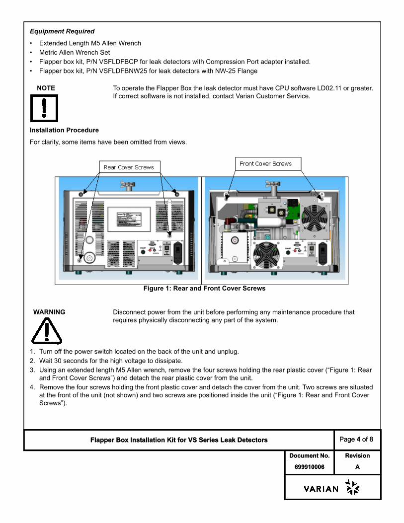
For clarity, some items have been omitted from views.
Figure 1: Rear and Front Cover Screws
WARNING Disconnect power from the unit before performing any maintenance procedure that requires physically disconnecting any part of the system.
1. Turn off the power switch located on the back of the unit and unplug.2. Wait 30 seconds for the high voltage to dissipate.3. Using an extended length M5 Allen wrench, remove the four screws holding the rear plastic cover (“Figure 1: Rear
and Front Cover Screws”) and detach the rear plastic cover from the unit.4. Remove the four screws holding the front plastic cover and detach the cover from the unit. Two screws are situated
at the front of the unit (not shown) and two screws are positioned inside the unit (“Figure 1: Rear and Front Cover Screws”).

Document No. Revision
-
Flapper Box Installation Kit for VS Series Leak Detectors Page 5 of 8
699910006 A
Document No. Revision
-
Flapper Box Installation Kit for VS Series Leak Detectors Page 5 of 8
699910006 A
Figure 2: Plastic Shield
5. Remove the two wing nuts holding the plastic shield around the leak detector power input area and remove the shield (“Figure 2: Plastic Shield”).
6. Remove the fan assembly by loosening the M4 socket head cap screw (“Figure 2: Plastic Shield”).
Figure 3: I/O Assembly with Screws
CAUTION Use proper ESD safety techniques when handling a PCB card.
7. Remove the two I/O board Phillips head screws w/lock washers and remove the I/O board that is installed in the unit (“Figure 3: I/O Assembly with Screws”).
8. Slide the I/O assembly back to allow room to connect the flapper box wiring harness to the I/O board.
Shield
M3 PhillipsHead Screws

Document No. Revision
-
Flapper Box Installation Kit for VS Series Leak Detectors Page 6 of 8
699910006 A
Document No. Revision
-
Flapper Box Installation Kit for VS Series Leak Detectors Page 6 of 8
699910006 A
Figure 4: I/O Bracket
9. Connect the P102 Molex receptacle on the flapper box wire harness to the J102 connector on the I/O board (“Figure 4: I/O Bracket”).
Figure 5: I/O Clip
10.Slide the I/O assembly into the leak detector and ensure that the I/O bracket engages the clip at the base of the leak detector (“Figure 5: I/O Clip”).
11.Reinstall the two I/O board Philips head screws w/lock washers (“Figure 3: I/O Assembly with Screws”).
Figure 6: Front Panel Removal
12.Remove M4 screw (“Figure 6: Front Panel Removal”) and open front panel to provide required room for installing the Flapper Box Wiring harness.
I/O J102
M-4 Screw

Document No. Revision
-
Flapper Box Installation Kit for VS Series Leak Detectors Page 7 of 8
699910006 A
Document No. Revision
-
Flapper Box Installation Kit for VS Series Leak Detectors Page 7 of 8
699910006 A
Figure 7: PCB Mounting Tray
13.Remove the M4 screws (“Figure 7: PCB Mounting Tray”) and gently lean the PCB Mounting Tray forward to gain access to the Flapper Box Wiring Harness.
Figure 8: Flapper Box Wiring Harness Layout
14.Install the Flapper Box Wiring Harness, as shown (“Figure 8: Flapper Box Wiring Harness Layout”), utilizing the top two wire clips, only use bottom wire clip, if accessible.
15.Reinstall the M4 screws (“Figure 7: PCB Mounting Tray”).16.Reinstall the M4 screw (“Figure 6: Front Panel Removal”).17.Reinstall the (“Figure 2: Plastic Shield”):• Fan assembly by tightening the M4 socket head screw.• The plastic shield using the two wing nuts.18.Attach the front cover and secure to the frame using existing hardware.
M-4 Screws

Document No. Revision
-
Flapper Box Installation Kit for VS Series Leak Detectors Page 8 of 8
699910006 A
Document No. Revision
-
Flapper Box Installation Kit for VS Series Leak Detectors Page 8 of 8
699910006 A
Figure 9: Front Cover Assembly
19.Carefully locate the Flapper Box Wire Harness leads between the front cover and the test port (“Figure 9: Front Cover Assembly”).
20.Attach the rear cover and secure the unit using existing hardware.
Figure 10: Flapper Box Assembly, NW25 Installation
21.Install the flapper box for:• P/N VSFLDFBNW25: Utilizing the NW-25 Centering Ring and Quick Clamp (“Figure 10: Flapper Box Assembly,
NW25 Installation”).• P/N VSFLDFBCP: Inserting the Flapper Box into leak detector's Compression Port Adapter and tighten.22.Connect the leads of the Flapper Box to the leads of the Wire Harness: Red to Red and Black to Black.23.Connect the power cord and power up the unit.24.Watch the home screen to verify that the Spectube Pressure Wait message progresses to Stabilization Wait and
System Ready within ten minutes.Refer to the operator's manual if the system fails to reach the System Ready mode.
25.Manually close the flapper box, the leak detector should transfer into test.26.After 30 seconds verify that the vent button is operational (the flapper box should open).27.Varian recommends a full calibration of the unit prior to leak test operations.
Flapper Box Wire Harness Leads

Sales and Service Offices
12/04
CanadaCentral coordination through:Varian, Inc.121 Hartwell AvenueLexington, MA 02421USATel: (781) 861 7200Fax: (781) 860 5437Toll Free: (800) 882 7426
ChinaVarian Technologies - BeijingRoom 1201, Jinyu MansionNo. 129A, Xuanwumen XidajieXicheng DistrictBeijing 1000031P.R. ChinaTel: (86) 10 6608 1031Fax: (86) 10 6608 1541
France and BeneluxVarian s.a.7 avenue des TropiquesZ.A. de Courtaboeuf – B.P. 12Les Ulis cedex (Orsay) 91941FranceTel: (33) 1 69 86 38 13Fax: (33) 1 69 28 23 08
Germany and AustriaVarian Deutschland GmbHAlsfelder Strasse 6Postfach 11 14 3564289 DarmstadtGermanyTel: (49) 6151 703 353Fax: (49) 6151 703 302
IndiaVarian India PVT LTD101-108, 1st Floor1010 Competent House7, Nangal Raya Business CentreNew Delhi 110 046IndiaTel: (91) 11 5548444Fax: (91) 11 5548445
ItalyVarian, Inc.Via F.lli Varian, 5410040 Leini, (Torino)ItalyTel (39) 011 997 9 111Fax (39) 011 997 9 350
JapanVarian, Inc.Sumitomo Shibaura Building, 8th Floor4-16-36 ShibauraMinato-ku, Tokyo 108JapanTel: (81) 3 5232 1253Fax: (81) 3 5232 1263
KoreaVarian Technologies Korea, Ltd.Shinsa 2nd Building 2F966-5 Daechi-dong Kangnam-gu, SeoulKorea 135-280Tel: (82) 2 3452 2452Fax: (82) 2 3452 2451
MexicoVarian S.A.Concepcion Beistegui No 109Col Del ValleC.P. 03100Mexico, D.F.Tel: (52) 5 523 9465Fax: (52) 5 523 9472
RussiaCentral coordination through:Varian, Inc.via F.lli Varian 5410040 Leini, (Torino)ItalyTel: (39) 011 997 9 252Fax: (39) 011 997 9 316
TaiwanVarian Technologies Asia Ltd. 18F-13 No.79, Hsin Tai Wu RoadSec. 1, Hsi Chih, Taipei HsienTaiwan, R.O.C.Tel: (886) 2 2698 9555Fax: (886) 2 2698 9678
UK and Ireland Varian Ltd.28 Manor RoadWalton-On-ThamesSurrey KT 12 2QFEnglandTel: (44) 1932 89 8000Fax: (44) 1932 22 8769
United StatesVarian, Inc.121 Hartwell AvenueLexington, MA 02421USATel: (781) 861 7200Fax: (781) 860 5437
Other CountriesVarian, Inc.
Via F.lli Varian 5410040 Leini, (Torino)ItalyTel: (39) 011 997 9 111Fax: (39) 011 997 9 350
Customer Support and Service:
North AmericaTel: 1 (800) 882-7426 (toll-free)[email protected]
EuropeTel: 00 (800) 234 234 00 (toll-free)[email protected]
JapanTel: (81) 3 5232 1253 (dedicated line)[email protected]
KoreaTel (82) 2 3452 2452 (dedicated line)[email protected]
TaiwanTel: 0 (800) 051 342 (toll-free)[email protected]
Worldwide Web Site, Catalog and On-line Orders:www.varianinc.com
Representatives in most countries
Sales and Service Offices