series e 11 – e 51 - home - röhren- und pumpenwerk … e 11 – e 51 version: i - 2015 ii manual...
TRANSCRIPT

OPERATING MANUAL for
RAINSTAR
Series E 11 – E 51
Version: I - 2015

II Manual for BAUER RAINSTAR Series E11–E51
Introduction
Thank you for buying BAUER RAINSTAR !
The present manual is a very important document that describes how to operate and BAUER RAINSTAR E. This manual describes the system as detailed as possible. If you need still more information, please contact your dealer or turn directly to BAUER in Voitsberg/Austria. Please note that the content of this manual neither constitutes part of nor alters in any way any previous or existing agreement, promise or legal relationship. BAUER’s commitment is based solely on the respective purchase contract which also contains the complete and only valid warranty agreement. Said contractual warranty is neither extended nor limited by the content of this manual. All information contained in the present manual is based on the latest product details available at the time of printing. BAUER reserves the right to change without notice without assuming any liability! BAUER RAINSTAR E is designed for highest performance safety and reliability provided it is operated in accordance with the present operating instructions. Therefore you should study this manual thoroughly before starting your BAUER RAINSTAR E ! Strictly observe all instructions pertaining to system handling, operation and service! On this condition, BAUER RAINSTAR E will operate to your satisfaction for many years!
Non-observance of this manual may cause personal injury or damage the equipment!
Please make this manual available to your staff. State the pump type and serial number of your BAUER RAINSTAR E in all inquiries, correspondence, warranty problems, or parts orders.
We wish you a lot of success with BAUER RAINSTAR !
This manual is to be considered an integral part of BAUER RAINSTAR E. Suppliers of both new and used systems are advised to put down in writing that they delivered the manual together with the system.

Manual for BAUER RAINSTAR Series E11–E51 III
Product details
Type designation: RAINSTAR
Type number: Baureihe E 11 , E 21 , E 31 , E 41 , E 51
Serial number1:
Dealer: Name:
Adresse:
ph./fax:
Date of shipment:
Manufacturer: Röhren- und Pumpenwerk BAUER Ges.m.b.H. Kowaldstr. 2 A - 8570 Voitsberg/Austria Tel.: +43 3142 200 – 0 Fax: +43 3142 200 –320 /-340 www.bauer-at.com
e-mail: [email protected]
Owner or operator: Name:
Address:
ph. / fax: Note: Please make a note of the type and serial number of your RAINSTAR and accessories. Be sure to specify these details every time you contact your dealer.
1In all warranty claims and correspondence relating to this machine it is essential to specify the full serial number group including all letters. This applies to both the machine and the components concerned. We cannot emphasise this point often enough.

IV Manual for BAUER RAINSTAR Series E11–E51
General Safety Instructions Symbols and terms
The CE symbol that has to be affixed on the machine by the manufacturer outwardly demonstrates compliance of the machine with the directives for machines and other relevant EU directives.
This “Warning” symbol refers to important safety instructions in this manual. Whenever you see this symbol be aware of possible injury hazards. Read the note following the symbol very carefully and inform the other operators accordingly.
Non-observance of this instruction may cause damage to or destroy
the machine or individual components.
It is very important to observe this note or condition!
Qualified operators are persons who on account of their training, experience and instruction as well as their knowledge of relevant standards, rules, precautions to be taken for accident prevention, and prevailing operating conditions, have been authorised by the person in charge of plant safety to perform the respective tasks required, and in doing so are able to recognise and avoid potential hazards. Among other things, knowledge of first-aid procedures is also required.
Product liability As defined by the product liability law every farmer is also an entrepreneur! According to §9 PHG (Product Liability Law), liability for damage to corporeal things caused by defective products is expressly excluded. This exclusion of liability also applies to parts not manufactured by BAUER itself but purchased from external suppliers.
Duty to furnish information Even if the customer passes on the machine later-on he is obliged to hand the operating manual on to the new receiver, too. The receiver of the machine must be instructed with reference to the mentioned regulations.
Intended use BAUER RAINSTAR is built exclusively for normal agricultural applications (intended use). Any use beyond this normal use is considered non-conforming. Manufacturer is not liable for damage resulting from such non-conforming use, the sole liability for damage from non-conforming use is with the user. Intended use also includes compliance with the manufacturer’s operating, maintenance and service instructions. The BAUER RAINSTAR may be used and operated only by persons who are familiar with the device and aware of the hazards involved. All rules for accident prevention as well as any other generally valid specifications and regulations relating to safety, work medicine and traffic law must be strictly observed. Unauthorised modifications on the machine release the manufacturer from liability for damage resulting therefrom.
WARNING!
CAUTION
NOTE

Manual for BAUER RAINSTAR Series E11–E51 V
INDEX
1 GENERAL INSTRUCTIONS FOR SAFETY AND ACCIDENT PREVENTION ................................................... 1
2 GENERAL ............................................................................................................................................................. 3
3 SAFETY PRECAUTIONS FOR RAINSTARS SERIES E 11-E51 ........................................................................ 4
4 DESCRIPTION ...................................................................................................................................................... 6
5 PUTTING INTO OPERATION ............................................................................................................................... 7
5.1 STEPS TO BE CARRIED OUT ONCE OR FROM TIME TO TIME ................................................................. 7 5.1.1 SymmetrIC WHEEL CART Assembly per sketch .................................................................................. 7 5.1.2 Asymmetric wheel cart assembly per sketch ......................................................................................... 7
5.2 TABLE FOR CONCRETE WEIGHTS REQUIRED ON SYMMETRIC CARTS ............................................... 9 5.3 MOUNTING THE MACHINE SUPPORTS ................................................................................................................ 10 5.4 MOUNTING AND ADJUSTING THE CART LIFT ......................................................................................... 11 5.5. OPERATING MODE I: PE-PIPE PULL-OFF ......................................................................................................... 12
5.5.1. Transport of machine to set-up position ............................................................................................... 12 5.5.2. LOWERING THE CART ....................................................................................................................... 13 5.5.3. PE-pipe pull-off ...................................................................................................................................... 13 5.5.4. Limiter for turbine regulation of tvr 60 turbine ....................................................................................... 15 5.5.5. SPEED ADJUSTMENT WITH ECO-STAR 4300 ................................................................................. 17
5.6. OPERATING MODE II: LAYING DOWN THE PE-PIPE .............................................................................. 18 5.6.1. FUNCTIONAL DESCRIPTION OF THE MAIN COMPONENTS .......................................................... 19 5.6.1.1. Machine drive – full-flow turbine ........................................................................................................... 19 5.6.2. PTO REWIND ....................................................................................................................................... 21
6 ECOSTAR 4300 ................................................................................................................................................. 23
6.1 GENERAL ....................................................................................................................................................... 23 6.2 DISPLAY WINDOWS AND MENU OVERVIEW ........................................................................................... 24 6.3 THE MOST COMMON COMBINATION OF DIFFERENT CONSTANTS ...................................................... 30 6.4 STOP - SENSOR .......................................................................................................................................... 31 6.5 OPERATION OF THE BAUER ECOSTAR 4300 ................................................................................................ 32
6.5.1 SPEED ADJUSTMENT ......................................................................................................................... 33 6.5.2 PRE – OR POST IRRIGATION ............................................................................................................ 33 6.5.3 START .................................................................................................................................................. 34 6.5.4 MONITORING ....................................................................................................................................... 35 6.5.5 STOP .................................................................................................................................................... 35
6.6 PRESSURE SWITCH ( OPTIONAL EQUIPMENT) ......................................................................................... 36 6.7 ERROR DESCRIPTION – ECO STAR 4300 ................................................................................................ 36 6.8 PROGRAMMING PROCEDURE ........................................................................................................................... 37 6.9 BATTERY ..................................................................................................................................................... 40
6.9.1 SOLAR PANEL ..................................................................................................................................... 41 6.9.2 CHECKING THE CONNECTIONS ....................................................................................................... 41 6.9.3 CHECKING THE LENGTH SENSOR ................................................................................................... 41 6.9.4 LIMIT STOP FOR TURBINES – REGULATING VALVE WITH ECOSTAR 4300 ................................ 42 6.9.5 SHORT CHECKLIST fOR ECOSTAR 4300 ......................................................................................... 42
7 OPTION - SMS .................................................................................................................................................... 43
8 CABLE CONNECTIONS –CONNECTION DIAGRAM ....................................................................................... 46
8.1.1 Checklist fOR ECOSTAR 4300............................................................................................................ 48 8.1.2 TaBLE FOR PRE-AND POST-IRRIGATION ........................................................................................ 52
9. EMERGENCY SHUT-OFF .................................................................................................................................. 52
10. WINDING MECHANISM .................................................................................................................................. 53
11. SHUT-OFF AND SAFETY EQUIPMENT ........................................................................................................ 54

VI Manual for BAUER RAINSTAR Series E11–E51
12. CART ............................................................................................................................................................... 54
13. SHUT-OFF VALVE – OVERPRESSURE (OPTION) ...................................................................................... 55
14. SHUT-OFF VALVE – LOW PRESSURE (OPTION) ....................................................................................... 55
15. COMBINED SHUT-OFF SYSTEM .................................................................................................................. 56
16 WINTERIZATION - DRAINING ...................................................................................................................... 57
16.1 DRAINING THE PE-PIPE .............................................................................................................................. 58 16.1.1 POSSIBLE FAULTS DURING PE-PIPE BLOW-OUT WITH COMPRESSOR ..................................... 60 16.1.2 SERVICE AND MAINTENANCE .......................................................................................................... 61
17 FAULT FINDING ............................................................................................................................................. 63
18 SETTING INSTRUCTIONS FOR RAINSTAR E 11 – E 51 ............................................................................. 64
18.1 SETTING THE SHIFTING GATE ................................................................................................................. 64 18.2 SETTING THE BAND BRAKE ON THE GEAR BOX ......................................................................................... 65 18.3 SETTING THE THREADED ROD ................................................................................................................ 65 18.4 INSPECTING THE BAND BRAKE FOR RELEASE OF THE BRAKE BAND ........................................................... 65 18.5 SETTING THE GEARBOX SHUT-OFF ........................................................................................................ 66 18.6 TESTING THE SHUT-OFF: .......................................................................................................................... 67 18.7 ADJUSTING THE WINDING MECHANISM ................................................................................................. 67 18.8 DESCRIPTION OF THE HYDRAULIC SYSTEM: ........................................................................................ 70 18.9 TIRE PRESSURE .............................................................................................................................................. 76
19 CONFORMITY CERTIFICATE ........................................................................................................................ 77

Manual for BAUER RAINSTAR Series E11-E51 1
1 GENERAL INSTRUCTIONS FOR SAFETY AND ACCIDENT PREVENTION
Check the operational safety of the machine before every start-up. 1. In addition to the instructions contained in this manual, all specifications generally valid for safety and
accident prevention must be observed! 2. The warning and instruction signs affixed to the machine give very important instructions for safe operation.
Observing them serves your own personal safety! 3. Never put the machine into operation unless all guards and safety devices are completely mounted and in
their proper working position! 4. Acquaint yourself with all equipment components and controls as well as their respective functions before
starting to work. It is too late when the device is already running! 5. The operator’s clothes should fit tightly. Avoid wearing loose clothes! 6. When handling slurry always keep in mind that the gasses produced are highly toxic and extremely
explosive in combination with oxygen. Therefore, open fires, light tests, sparking and smoking are strictly forbidden!
7. Utmost care is required with regard to gasses in slurry and dung channels at open valves to the preliminary pit, before the main pit, or at cross channels. The same applies to mixing and withdrawal points when mixers or pumps are running!
8. When handling slurry always ensure sufficient ventilation! 9. Keep the machine clean to avoid fire hazards! Tractor-driven machines 1. Before starting inspect the area around the machine (Children) ! Make sure your view is unrestricted! 2. Riding on the machine during transport is forbidden! 3. Couple the machine according to instructions and fasten it only at the specified points! 4. Be especially careful when coupling the machine to the tractor or uncoupling it! 5. Always adjust the supports in the proper position when coupling or uncoupling the machine (stability)! 6. Always mount balancing weights properly at the points provided! 7. Observe restrictions pertaining to axle load, total weight, and transport dimensions! 8. Inspect and mount all items required for transport such as lighting, warning signals and possible safety
devices! 9. Mounted or trailed machines as well as balancing weights influence road behaviour, steering and braking
capacity. Therefore make sure that proper steering and braking are possible! 10. Consider the projection and/or centrifugal mass of the machine when driving in curves! 11. It is forbidden to stay in the working range of the machine while it is operating ! 12. Keep out of the turning and swivelling range of the machine! 13. Only operate hinged hydraulic frames when nobody is in the swivel range! 14. Externally powered machines (e.g. hydraulic) bear a crushing and shearing hazard! 15. Nobody is allowed between the tractor and the implement unless the tractor is secured by the parking brake
and /or wedges under the wheels! 16. Hinged supports must always be folded up and secured before driving away! 17. Secure the machine and the tractor against rolling! Tractor-mounted machines 1. Before a machine is linked to or detached from the three-point linkage, the control device must be shifted to
a position in which unintentional lifting or lowering is impossible! 2. When using the three-point linkage the linkage parameters of both tractor and attached machine must
correspond, if not, they have to be matched accordingly! 3. The three-point linkage bears crushing and shearing hazards! 4. When operating the external control of the three-point linkage never step in-between tractor and the
machine! 5. When the machine is in the transport position make sure that the tractor’s links are always properly secured
on the sides. 6. When driving on the road with the machine lifted the control lever must be locked against lowering!

2 Manual for BAUER RAINSTAR Series E11–E51
Trailed machines 1. When a machine is coupled to the drawbar make sure that the coupling point provides sufficient flexibility! Power take-off (applies only to PTO driven machines) 1. It is not allowed to use any other types of PTO drive shafts except the ones prescribed by the manufacturer! 2. Drive-shaft guard tube and guard cone as well as the PTO guard – also on the machine side - must be
mounted and in good working order! 3. When using a PTO drive shaft always observe the specified overlap in transport and working position! 4. Never connect or disconnect the PTO drive shaft unless the PTO is stopped, the engine turned off, and
the ignition key pulled out! 5. Make sure the drive shaft is always connected and secured properly! 6. Attach the safety chain to keep the drive shaft guard from rotating with the shaft! 7. Before you turn on the PTO make sure that the selected tractor PTO speed corresponds with the
permissible implement speed! 8. Before starting the PTO make sure that nobody is standing in the danger zone of the machine! 9. Never turn on the PTO when the engine is turned off or during a transport drive! 10. When working with the PTO nobody is allowed near the turning PTO or drive shaft! 11. Warning! The PTO shaft may continue turning due to its centrifugal mass after the PTO has been turned
off! Keep clear of the machine during this time and do not touch until the PTO shaft stands absolutely still!
12. For cleaning, greasing, or adjusting the PTO driven implement or drive shaft, PTO and engine must be switched off and the ignition key pulled out!
13. Place the disconnected drive shaft on the provided support! 14. When drive shaft has been removed put the guard on the PTO shaft! 15. If a defect occurs repair it immediately before starting to work with the machine! Hydraulic system 1. Hydraulic system is under high pressure! 2. When connecting hydraulic cylinders and motors, make sure the hydraulic hoses are connected as
specified! 3. Before coupling the hydraulic hoses with the tractor’s hydraulic system make sure that the entire
hydraulic system is pressureless both on the tractor and implement side ! 4. Inspect the hydraulic lines at regular intervals and replace them immediately in case of defects or ageing.
Replaced hoses must comply with the technical specifications of the implement manufacturer! 5. When looking for leaks use only suitable equipment because of the injury hazard involved! 6. Liquids emerging under high pressure (hydraulic oil) may penetrate the skin and cause serious injuries!
An injured person must see a doctor immediately! Danger of infection! 7. Before working on the hydraulic system the machine must be lowered, the system depressurised and the
engine turned off!
Electric-driven implements
1. All work beyond normal maintenance of the implement should be performed only by a professional electrician! 2. Defective or broken plugs and sockets must be replaced by a professional electrician! 3. Never pull a plug out of the socket at the flexible electric cord! 4. Extension cables for power supply should be used only temporarily! Never use such lines permanently as
a substitute for the required fixed installations! 5. Flexible lines laid across traffic areas on the farm must have at least 5 m ground clearance! 6. Always turn off the power supply before you do any work on the machine! 7. Check all electric lines for visible defects before you put the machine into operation! Replace defective
cables and do not start the machine before that! 8. Never use electric-driven implements in damp situations or locations exposed to fire hazard unless they
are adequately protected against moisture and dust! 9. Covering electric motors may cause heat concentration with high temperatures which could destroy the
operating equipment and cause fires!
Manual for BAUER RAINSTAR Series E11-E51 3
Hand-operated devices (valves) 1. Because of the slurry gasses produced in the lines, no slurry is allowed to remain in closed pipelines –
bursting hazard! 2. Lay the pipelines with sufficient inclination and make sure that the selected closing order of valves allows all
lines to be drained completely! 3. Protect the valves against unauthorised handling! 4. If a valve gets jammed do not apply force! Use only the operating levers supplied with the implement! 5. Observe the permissible maximum operating pressure of valves and pipelines when pumps are operated! 6. Service only when the tanks are empty! Maintenance 1. Never perform any maintenance, service or cleaning work or fault elimination steps unless the drive is
turned off and the engine is standing still! 2. Check proper fit of all nuts and bolts regularly and tighten them, if necessary. 3. If maintenance work is required on the lifted machine always secure it by means of appropriate supports! 4. When exchanging tools with cutting edges always use proper tools and wear safe protective gloves. 5. Dispose of oil, grease and filters according to local laws and regulations! 6. Always turn off power before working on the electric system! 7. Before electric welding on the tractor and mounted machines the generator and battery cables must be
disconnected! 8. Spare parts must meet manufacturer’s minimum technical specifications! This is the case for instance with
original spare parts for instance!
2 GENERAL
BAUER products are designed and manufactured carefully, subject to a system of continuous quality control. BAUER RAINSTAR models E 11, E 21, E 31, E 41, E 51 are turbine-driven machines designed for fully mechanised and labour-saving irrigation. Individual pipe sets are no longer laid down by hand; system set-up, repositioning, and operation are all done with the tractor only. BAUER RAINSTAR is a universal machine suitable of covering fields of varying lengths and widths. There is no need for supervision while the system is operating. Strict observance of all operating and service instructions in this manual is the basic prerequisite for many years of trouble-free operation. Therefore please make sure that all operators on your staff are familiar with the instructions given in this manual. The model number as well as the serial number (Vehicle identification number) are stamped into the nameplate. In addition, the serial number is stamped into the frame of the undercarriage. Please state these data in all your inquiries, correspondence, warranty matters and parts orders. We warrant according to our General Terms of Sale.
4 Manual for BAUER RAINSTAR Series E11–E51
3 SAFETY PRECAUTIONS FOR RAINSTARS SERIES E 11-E51
1. Read this manual before you put the system into operation for the first time. 2. Never handle the PE-pipe near the device or the device itself during pull-off or retraction. 3. During PE-pipe rewind with the tractor’s PTO or during pipe pull-off, always make sure that the shifting lever is in the proper position. Moreover, the maximum permissible speed must not be exceeded.
Danger by improper handling!
4. Never service or set any part of the system (except speed settings) while it is operating. 5. Keep clear of all moving parts. 6. Never expose any moving parts by removing protective elements. 7. Keep a safe distance from the sprinkler during operation. 8. Be careful in case of high connecting pressure! 9. Make sure that the water jet from spray nozzles does not hit public roads. 10. The RAINSTAR licensed for transport in agricultural operation only. For transportation on public roads all applicable traffic requirements must be strictly adhered to.
For safety reasons it is not allowed to transport the RAINSTAR by pulling it with a fork-type drawbar (OPTIONAL) and the toolbar!
11. When loading the machine on a trailer note that the water remaining in the pipe shifts the system’s centre
of gravity upward. 12. When driving in curves with the RAINSTAR loaded on a trailer, the permissible maximum driving speed is
considerably reduced dependent on the position of the RAINSTAR’s centre of gravity! 13. Always ensure that the locks and stops are secured according to the machine’s general conditions for
transport. 14. Before starting to irrigate near electric power lines you should contact your local power supply company
regarding safe distances that have to be allowed. 15. Maximum permissible speed: 10 km/h
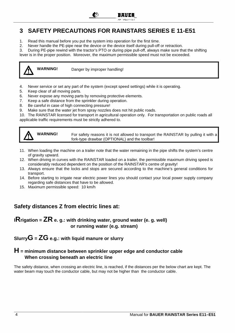
Safety distances Z from electric lines at:
IRrigation = ZR e. g.: with drinking water, ground water (e. g. well) or running water (e.g. stream)
SlurryG = ZG e.g.: with liquid manure or slurry
H = minimum distance between sprinkler upper edge and conductor cable When crossing beneath an electric line The safety distance, when crossing an electric line, is reached, if the distances per the below chart are kept. The water beam may touch the conductor cable, but may not be higher than the conductor cable.
WARNING!
WARNING!
Manual for BAUER RAINSTAR Series E11-E51 5
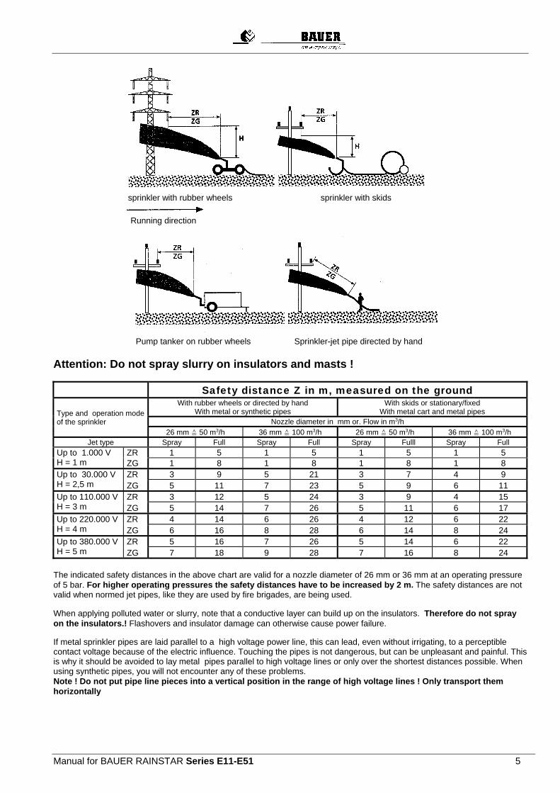
sprinkler with rubber wheels sprinkler with skids
Running direction
Pump tanker on rubber wheels Sprinkler-jet pipe directed by hand
Attention: Do not spray slurry on insulators and masts !
Safety distance Z in m, measured on the ground
Type and operation mode of the sprinkler
With rubber wheels or directed by hand With metal or synthetic pipes
With skids or stationary/fixed With metal cart and metal pipes
Nozzle diameter in mm or. Flow in m3/h
26 mm ≙ 50 m3/h 36 mm ≙ 100 m3/h 26 mm ≙ 50 m3/h 36 mm ≙ 100 m3/h Jet type Spray Full Spray Full Spray Fulll Spray Full
Up to 1.000 V H = 1 m
ZR 1 5 1 5 1 5 1 5 ZG 1 8 1 8 1 8 1 8
Up to 30.000 V H = 2,5 m
ZR 3 9 5 21 3 7 4 9 ZG 5 11 7 23 5 9 6 11
Up to 110.000 V H = 3 m
ZR 3 12 5 24 3 9 4 15 ZG 5 14 7 26 5 11 6 17
Up to 220.000 V H = 4 m
ZR 4 14 6 26 4 12 6 22 ZG 6 16 8 28 6 14 8 24
Up to 380.000 V H = 5 m
ZR 5 16 7 26 5 14 6 22 ZG 7 18 9 28 7 16 8 24
The indicated safety distances in the above chart are valid for a nozzle diameter of 26 mm or 36 mm at an operating pressure of 5 bar. For higher operating pressures the safety distances have to be increased by 2 m. The safety distances are not valid when normed jet pipes, like they are used by fire brigades, are being used. When applying polluted water or slurry, note that a conductive layer can build up on the insulators. Therefore do not spray on the insulators.! Flashovers and insulator damage can otherwise cause power failure. If metal sprinkler pipes are laid parallel to a high voltage power line, this can lead, even without irrigating, to a perceptible contact voltage because of the electric influence. Touching the pipes is not dangerous, but can be unpleasant and painful. This is why it should be avoided to lay metal pipes parallel to high voltage lines or only over the shortest distances possible. When using synthetic pipes, you will not encounter any of these problems. Note ! Do not put pipe line pieces into a vertical position in the range of high voltage lines ! Only transport them horizontally
6 Manual for BAUER RAINSTAR Series E11–E51
4 DESCRIPTION
The RAINSTAR is a universal irrigation machine for varying lengths and widths of fields and best suited for sprinkling cereal crops, field crops, root crops, and horticultures as well as any kind of grassland. The main components of the RAINSTAR are a two-wheel undercarriage on which is mounted the turntable swiveling through 270°, and the reel with the special PE-pipe, the multifunctional compact gearbox and the TVR 60 turbine, and the high-rise cart that is ideal particularly for high crops, with the BAUER wide-range gun. The material of the PE-pipe corresponds to the latest findings of the art. One end of the pipe connects to the reel drum and to the water supply through its axle. The other end of the pipe is coupled with the high-rise cart. The cart’s track width is infinitely adjustable (see Technical Data). The heart of the RAINSTAR is the TVR 60 turbine. This is a full-flow turbine mounted in a flow-promoting position directly on the reel. They are nearly insensitive to soiled water and offer maximum efficiency. The drive shaft is made of stainless steel. The regulating flap inside the turbine is coated with a wear-proof rubber lining. The lifetime lubricated drive shaft bearing is sealed by a maintenance-free mechanical seal. The TVR 60 turbine is designed for water flow rates from 20 to over 120 m³/h and features a wide control range. Impeller speeds range from 150 to 650 rpm. The cart retraction speed is infinitely variable. It is adjusted by means of the ECOSTAR and can be read from the display. Depending on the available water flow and connecting pressure, it may vary between 8 and 150 m/h. The connecting pressure at the machine should not exceed 11 bar. Power is directly transmitted from the turbine to the change-speed gearbox and the chain drive onto the reel. A band brake prevents fast reverse rotation of the reel in the final shut-off position, when the PE-pipe is stretched. The band brake as well as gearwheels in the oil-filled change-speed gearbox act as a brake and prevent the PE-pipe windings on the reel from loosening during pipe pull-out. For safety reasons the drive is fitted with an emergency stop and a reversing stop as well. With this emergency stop device the drive can be stopped immediately by hand.
Never remove the drive cover before you have turned off the water supply to the machine and slackened the stretched PE-pipe.
To slacken the stretched PE-pipe move the gear shift lever downward carefully (see proper procedure on page13). A winding carriage moved by a helically grooved spindle ensures that the PE-pipe is wound up properly on all layers. To keep the retraction speed constant on all layers independent of the pipe length still lying on the field, the RAINSTAR is equipped with an ECOSTAR 4300. At the end of the irrigation strip the automatic drive shut-off is actuated by rods. If the machine is equipped with an overpressure-actuated shut-off valve the water supply to the machine is shut off simultaneously. If a low-pressure operated shut-off valve is mounted, the pumping unit is shut off. After shut-off the rear hydraulic machine supports can be withdrawn. In doing so the cart is raised automatically into the transport position. Without any further preparations the RAINSTAR can be transported to its next setting-up position immediately. Pull off or lay down the PE-pipe again, connect the water supply, and the machine is ready for the next run. When driving on public roads the reel must be turned into the driving direction and secured with the lock bolt. The PE-pipe must be fully wound up on the reel and the cart lifted. The jack and both rear machine supports must be withdrawn to their uppermost position.. On public roads the drawbar and coupling ring must be hitched to the tractor’s yoke and secured with the pin.. The maximum permissible driving speed of 10 km/h must be observed. For increased safety against overturning in curves we recommend to set the maximum possible track width. On principle, it is possible to transport the machine between hydrants in the field with the cart lifted on the side. In this configuration the driving speed must always be adapted to the existing conditions and should never exceed 5 km/h. You must also take into consideration that this type of transport requires a wider driving lane.
WARNING!

Manual for BAUER RAINSTAR Series E11-E51 7
5 PUTTING INTO OPERATION
Before and during the first start-up grease all bearings, chains and guide parts of the winding mechanism. Use normal ball bearing grease for all bearing assemblies with grease nipples, and a viscous and durable type of grease for chains, guide rods and joints. Tighten the wheel nuts before the first operation and check the tires for the specified pressure (see technical Data). Tighten also the connecting bolts, the connection of the turntable side member on the undercarriage, the ball race on the undercarriage, and the fastening of the hitch eye, according to the “Service and Maintenance“ table.
5.1 STEPS TO BE CARRIED OUT ONCE OR FROM TIME TO TIME
5.1.1 SYMMETRIC WHEEL CART ASSEMBLY PER SKETCH
5.1.2 ASYMMETRIC WHEEL CART ASSEMBLY PER SKETCH
Note: If you use a blow-out device, the stop valve has to be mounted between cart flange and sprinkler pendulum tube.

Manual for BAUER RAINSTAR Series E11–E518
Symmetric wheel cart
Asymmetric wheel cart
Note : front bolt for fastening the sprinkler to be mounted from below (way of the pendulum)
Set the required track width on cart and undercarriage depending on the existing type of crop.
Place the appropriate number of balancing weights on the balancing pendulum of the cart.
The number of weights required depends on cart track width setting, nozzle diameter, and nozzle pressure.

Manual for BAUER RAINSTAR series E11–E51 9
5.2 TABLE FOR CONCRETE WEIGHTS REQUIRED ON SYMMETRIC CARTS
Nozzle pressure in bar
3,0 4,0 5,0 6,0
Position A B A B A B A B Nozzle Ø 26 3 1 3 1 3 1 3 2 in mm 28 3 1 3 1 3 2 3 2
30 3 1 3 1 3 2 3 3
32 3 1 3 2 3 3 3 3
34 3 2 3 2 3 3 3 4
36 3 2 3 3 3 4 3 4
The number of required weights is for track 1500 to 2800 mm
Note: When using an asymmetric wheel cart, additional 2 weights have to be mounted on the wheel carrier opposite the inlet (PE pipe) in addition to the weights specified above!
Set the sector on the wide-range sprinkler (ar. 220° for full track width). Further instructions see in manual for sprinkler. The VARI-ANGLE can be adjusted to the existing wind conditions by adapting the trajectory angle.

Manual for BAUER RAINSTAR Series E11–E51 10
5.3 MOUNTING THE MACHINE SUPPORTS Set up the RAINSTAR on level ground in an all-round horizontal position. The right and left machine supports are shipped in a wooden crate. Mount the supports on the machine as described below: Mount the two anchoring shields (1), which are shipped loose, on both support legs according to the drawing with the lock bolt (3). Fasten the lower support brace (4) with the bolt (2).
In special situations, e.g. if the path on which the RAINSTAR sits is slightly inclined, the anchoring shield can be mounted extended by 120 mm.
Version from 2013 Version to 2012 The new design of the anchoring shield (1) with a round connection part allows to swivel it by 180 degree by taking off the lock bolt (3). This means a higher ground clearance, which makes transportation easier. Before mounting the right support, take off the cover (15). Put the pre-mounted right support leg into engagement with the guide (5) and fasten it to the turntable side frame (7) with the bolt (6) (per the drawing). Mount the support lift (8) in the turntable side frame with the bolt, turn up the fork and screw it with the bolt (9). Proceed the same way with the left machine support.

Manual for BAUER RAINSTAR series E11–E51 11
5.4 MOUNTING AND ADJUSTING THE CART LIFT
Mount the cart lift (10) according to the sketch . (Stop brackets pointing upward). Move the cross beam height X , adjust the set screw (11) and secure them. Mount both square washers (12) on the lower braces (4). ( see Section 5.3 ) Push the upper brace (13) over the lower brace (4). Lift the cart lift bracket (10) and screw it with the braces in such a way that it can swivel.
X * X *** Typ
1750mm / 69 inch 1550mm / 61 inch E11-E51
1850mm / 73 inch 1650mm / 65 inch E11-E51 / 4W
1850mm / 73 inch 1650mm / 65 inch E11-E51 / 4WB
X *, X *** see section 5.3
Check setting dimension of cart lift bracket when mounting the machine ATTENTION
X
Manual for BAUER RAINSTAR Series E11–E51 12
5.5. OPERATING MODE I: PE-PIPE PULL-OFF
5.5.1. TRANSPORT OF MACHINE TO SET-UP POSITION
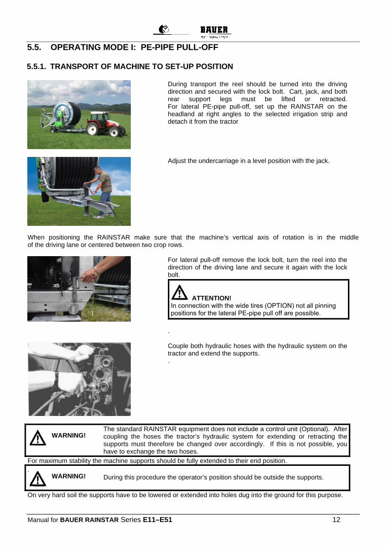
During transport the reel should be turned into the driving direction and secured with the lock bolt. Cart, jack, and both rear support legs must be lifted or retracted. For lateral PE-pipe pull-off, set up the RAINSTAR on the headland at right angles to the selected irrigation strip and detach it from the tractor
Adjust the undercarriage in a level position with the jack.
When positioning the RAINSTAR make sure that the machine’s vertical axis of rotation is in the middle of the driving lane or centered between two crop rows.
For lateral pull-off remove the lock bolt, turn the reel into the direction of the driving lane and secure it again with the lock bolt.
.
ATTENTION! In connection with the wide tires (OPTION) not all pinningpositions for the lateral PE-pipe pull off are possible.
Couple both hydraulic hoses with the hydraulic system on the tractor and extend the supports. .
The standard RAINSTAR equipment does not include a control unit (Optional). After coupling the hoses the tractor’s hydraulic system for extending or retracting the supports must therefore be changed over accordingly. If this is not possible, you have to exchange the two hoses.
For maximum stability the machine supports should be fully extended to their end position. .
During this procedure the operator’s position should be outside the supports.
On very hard soil the supports have to be lowered or extended into holes dug into the ground for this purpose.
WARNING!
WARNING!
Manual for BAUER RAINSTAR series E11–E51 13
5.5.2. LOWERING THE CART
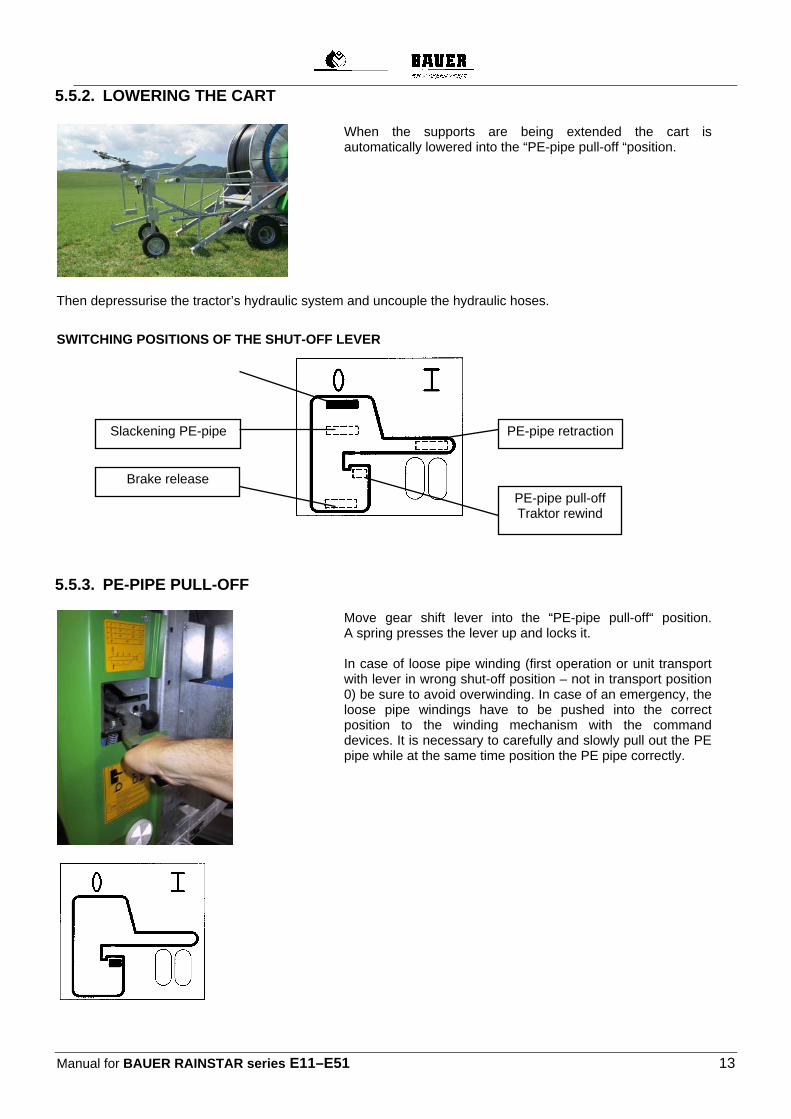
When the supports are being extended the cart is automatically lowered into the “PE-pipe pull-off “position.
Then depressurise the tractor’s hydraulic system and uncouple the hydraulic hoses.
SWITCHING POSITIONS OF THE SHUT-OFF LEVER
5.5.3. PE-PIPE PULL-OFF
Move gear shift lever into the “PE-pipe pull-off“ position.A spring presses the lever up and locks it. In case of loose pipe winding (first operation or unit transport with lever in wrong shut-off position – not in transport position 0) be sure to avoid overwinding. In case of an emergency, the loose pipe windings have to be pushed into the correct position to the winding mechanism with the command devices. It is necessary to carefully and slowly pull out the PE pipe while at the same time position the PE pipe correctly.
Slackening PE-pipe PE-pipe retraction
Brake release
PE-pipe pull-off Traktor rewind
Manual for BAUER RAINSTAR Series E11–E51 14
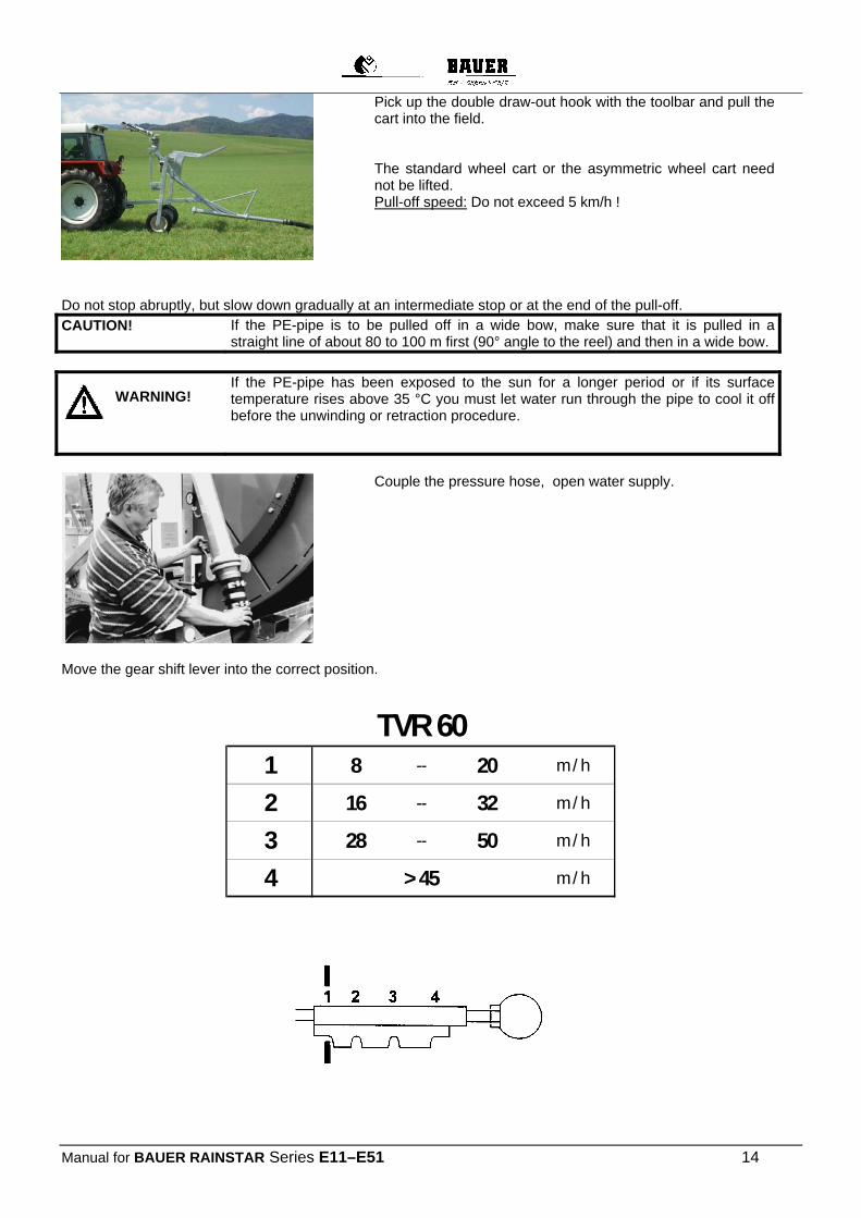
Pick up the double draw-out hook with the toolbar and pull the cart into the field. The standard wheel cart or the asymmetric wheel cart need not be lifted. Pull-off speed: Do not exceed 5 km/h !
Do not stop abruptly, but slow down gradually at an intermediate stop or at the end of the pull-off.
CAUTION!
If the PE-pipe is to be pulled off in a wide bow, make sure that it is pulled in a straight line of about 80 to 100 m first (90° angle to the reel) and then in a wide bow.
If the PE-pipe has been exposed to the sun for a longer period or if its surface
temperature rises above 35 °C you must let water run through the pipe to cool it off before the unwinding or retraction procedure.
Couple the pressure hose, open water supply.
Move the gear shift lever into the correct position.
TVR 601 8 -- 20 m / h
2 16 -- 32 m / h
3 28 -- 50 m / h
4 > 45 m / h
WARNING!
Manual for BAUER RAINSTAR series E11–E51 15
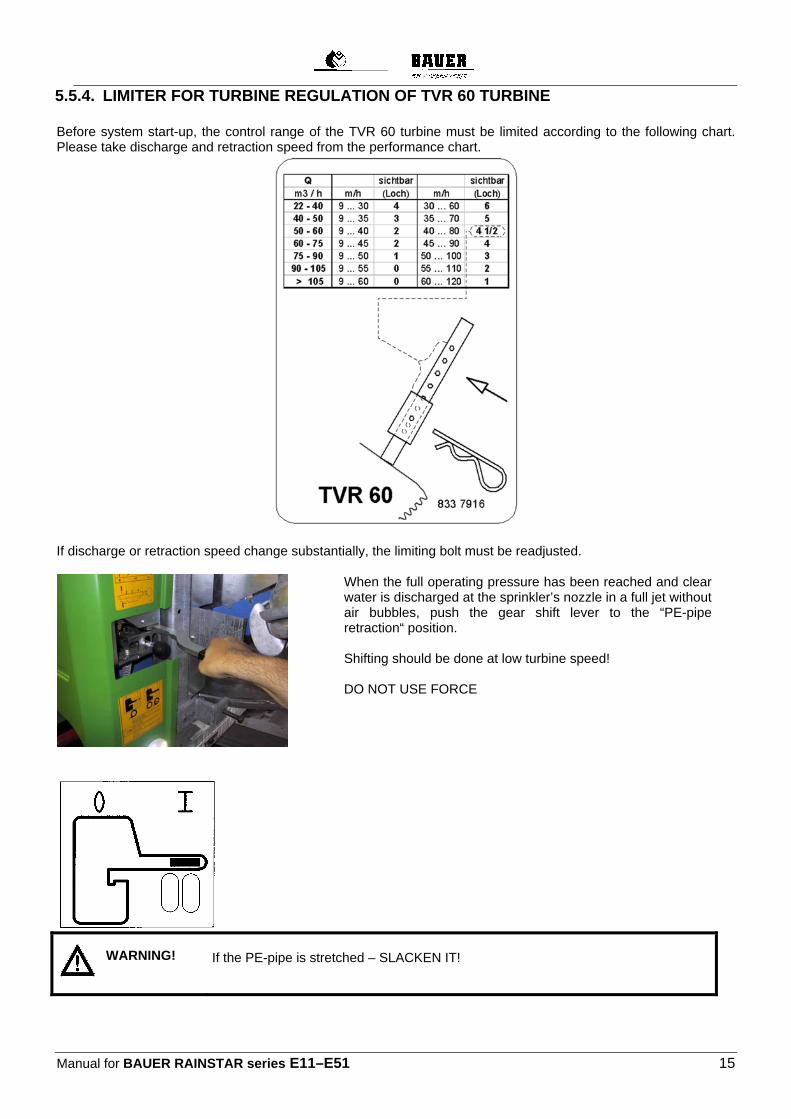
5.5.4. LIMITER FOR TURBINE REGULATION OF TVR 60 TURBINE Before system start-up, the control range of the TVR 60 turbine must be limited according to the following chart. Please take discharge and retraction speed from the performance chart.
If discharge or retraction speed change substantially, the limiting bolt must be readjusted.
When the full operating pressure has been reached and clear water is discharged at the sprinkler’s nozzle in a full jet without air bubbles, push the gear shift lever to the “PE-pipe retraction“ position. Shifting should be done at low turbine speed! DO NOT USE FORCE
If the PE-pipe is stretched – SLACKEN IT!
WARNING!

Manual for BAUER RAINSTAR Series E11–E51 16
Proper procedure:
Pull the shut-off lever into the shut-off position ....
... and slacken the PE-pipe by carefully pressing the shut-off lever downward.
CAUTION!
Switching into the gear speeds 1 to 4 is only possible when the turbine is rotating!
CAUTION!
Move the gear shift lever into the desired position and set back the shut-off lever to the “PE-pipe retraction“ position.
The reel starts to rewind the PE-pipe.
Manual for BAUER RAINSTAR series E11–E51 17
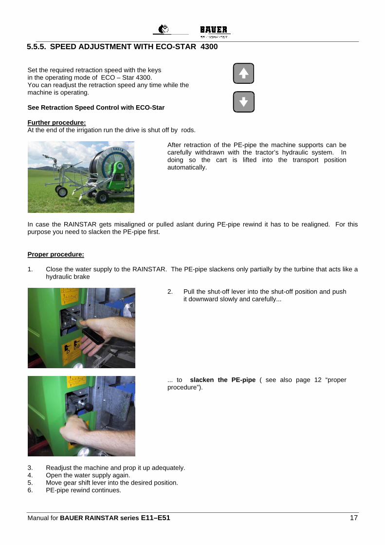
5.5.5. SPEED ADJUSTMENT WITH ECO-STAR 4300 Set the required retraction speed with the keys in the operating mode of ECO – Star 4300. You can readjust the retraction speed any time while the machine is operating. See Retraction Speed Control with ECO-Star Further procedure: At the end of the irrigation run the drive is shut off by rods.
After retraction of the PE-pipe the machine supports can be carefully withdrawn with the tractor’s hydraulic system. In doing so the cart is lifted into the transport position automatically.
In case the RAINSTAR gets misaligned or pulled aslant during PE-pipe rewind it has to be realigned. For this purpose you need to slacken the PE-pipe first. Proper procedure: 1. Close the water supply to the RAINSTAR. The PE-pipe slackens only partially by the turbine that acts like a
hydraulic brake
2. Pull the shut-off lever into the shut-off position and push it downward slowly and carefully...
... to slacken the PE-pipe ( see also page 12 “proper procedure”).
3. Readjust the machine and prop it up adequately. 4. Open the water supply again. 5. Move gear shift lever into the desired position. 6. PE-pipe rewind continues.

Manual for BAUER RAINSTAR Series E11–E51 18
5.6. OPERATING MODE II: LAYING DOWN THE PE-PIPE In addition to the pull-off method the PE-pipe can also be laid down on the ground. This method is mostly used in situations where heavy soil makes it impossible to pull the cart across the field or where the field is longer than one or two times the PE-pipe length. Moreover, the laying down method allows using smaller tractors because no pulling forces are applied on the pipe. Drive into the field with the RAINSTAR allowing for the sprinkler’s distance of throw.
*) W = distance of throw of the sprinkler
Lower the cart as described under Operating mode I, “Lowering the cart” and anchor it slightly.
Now move forward with the machine for about 2 to 3 metres, retract the machine supports and continue across the field.
Extending and retracting of the machine support is made much easier with the “control valve block - supports” option.
Manual for BAUER RAINSTAR series E11–E51 19
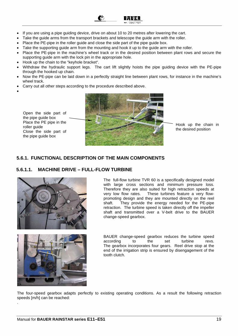
If you are using a pipe guiding device, drive on about 10 to 20 metres after lowering the cart. Take the guide arms from the transport brackets and telescope the guide arm with the roller. Place the PE-pipe in the roller guide and close the side part of the pipe guide box. Take the supporting guide arm from the mounting and hook it up to the guide arm with the roller. Place the PE-pipe in the machine’s wheel track or in the desired position between plant rows and secure the
supporting guide arm with the lock pin in the appropriate hole. Hook up the chain to the “keyhole bracket“. Withdraw the hydraulic support legs. The cart lift slightly hoists the pipe guiding device with the PE-pipe
through the hooked up chain. Now the PE-pipe can be laid down in a perfectly straight line between plant rows, for instance in the machine’s
wheel track. Carry out all other steps according to the procedure described above.
5.6.1. FUNCTIONAL DESCRIPTION OF THE MAIN COMPONENTS
5.6.1.1. MACHINE DRIVE – FULL-FLOW TURBINE
The full-flow turbine TVR 60 is a specifically designed model with large cross sections and minimum pressure loss. Therefore they are also suited for high retraction speeds at very low flow rates. These turbines feature a very flow-promoting design and they are mounted directly on the reel shaft. They provide the energy needed for the PE-pipe retraction. The turbine speed is taken directly off the impeller shaft and transmitted over a V-belt drive to the BAUER change-speed gearbox.
BAUER change-speed gearbox reduces the turbine speed according to the set turbine revs. The gearbox incorporates four gears. Reel drive stop at the end of the irrigation strip is ensured by disengagement of the tooth clutch.
The four-speed gearbox adapts perfectly to existing operating conditions. As a result the following retraction speeds [m/h] can be reached: .
Hook up the chain in the desired position
Open the side part of the pipe guide box Place the PE pipe in the roller guide Close the side part of the pipe guide box
Manual for BAUER RAINSTAR Series E11–E51 20
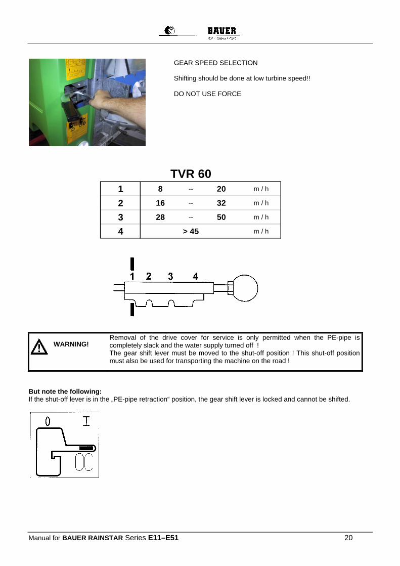
GEAR SPEED SELECTION Shifting should be done at low turbine speed!! DO NOT USE FORCE
TVR 601 8 -- 20 m / h
2 16 -- 32 m / h
3 28 -- 50 m / h
4 > 45 m / h
Removal of the drive cover for service is only permitted when the PE-pipe is completely slack and the water supply turned off ! The gear shift lever must be moved to the shut-off position ! This shut-off position must also be used for transporting the machine on the road !
But note the following: If the shut-off lever is in the „PE-pipe retraction“ position, the gear shift lever is locked and cannot be shifted.
WARNING!

Manual for BAUER RAINSTAR series E11–E51 21
If the shut-off lever is in the „PE-pipe pull off“ position.
or shut-off position you can shift it to the required gears 1 to 4.
Before shifting gears – slacken the PE-pipe ! Always shift gears at low turbine speed!
If the shut-off lever is in the shut-off position, press the lever down slowly and carefully so that the band brake is released and the PE-pipe slackens (see also page 13).
5.6.2. PTO REWIND
If required, you can rewind the PE-pipe also with the tractors PTO system Rewind only under water pressure ( oval PE-pipe ) PTO speed = max. 540 rpm
WARNING!
WARNING!
Manual for BAUER RAINSTAR Series E11–E51 22
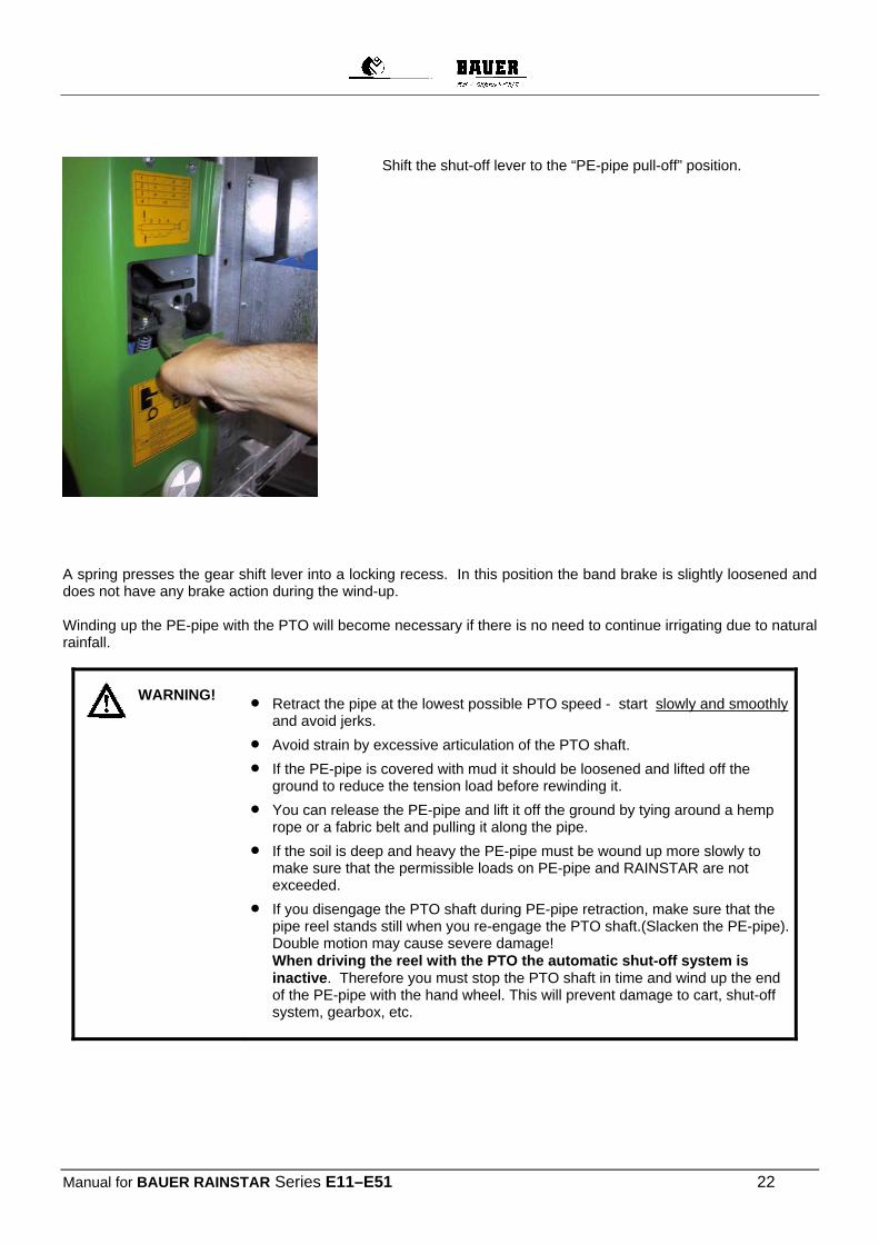
Shift the shut-off lever to the “PE-pipe pull-off” position.
A spring presses the gear shift lever into a locking recess. In this position the band brake is slightly loosened and does not have any brake action during the wind-up. Winding up the PE-pipe with the PTO will become necessary if there is no need to continue irrigating due to natural rainfall.
Retract the pipe at the lowest possible PTO speed - start slowly and smoothly and avoid jerks.
Avoid strain by excessive articulation of the PTO shaft.
If the PE-pipe is covered with mud it should be loosened and lifted off the ground to reduce the tension load before rewinding it.
You can release the PE-pipe and lift it off the ground by tying around a hemp rope or a fabric belt and pulling it along the pipe.
If the soil is deep and heavy the PE-pipe must be wound up more slowly to make sure that the permissible loads on PE-pipe and RAINSTAR are not exceeded.
If you disengage the PTO shaft during PE-pipe retraction, make sure that the pipe reel stands still when you re-engage the PTO shaft.(Slacken the PE-pipe).Double motion may cause severe damage! When driving the reel with the PTO the automatic shut-off system is inactive. Therefore you must stop the PTO shaft in time and wind up the end of the PE-pipe with the hand wheel. This will prevent damage to cart, shut-off system, gearbox, etc.
WARNING!
Manual for BAUER RAINSTAR series E11–E51 23
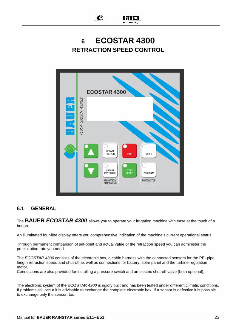
6 ECOSTAR 4300 RETRACTION SPEED CONTROL
6.1 GENERAL
The BAUER ECOSTAR 4300 allows you to operate your irrigation machine with ease at the touch of a button. An illuminated four-line display offers you comprehensive indication of the machine’s current operational status. Through permanent comparison of set-point and actual value of the retraction speed you can administer the precipitation rate you need. The ECOSTAR 4300 consists of the electronic box, a cable harness with the connected sensors for the PE- pipe length retraction speed and shut-off as well as connections for battery, solar panel and the turbine regulation motor. Connections are also provided for installing a pressure switch and an electric shut-off valve (both optional). The electronic system of the ECOSTAR 4300 is rigidly built and has been tested under different climatic conditions. If problems still occur it is advisable to exchange the complete electronic box. If a sensor is defective it is possible to exchange only the sensor, too.
Manual for BAUER RAINSTAR Series E11–E51 24
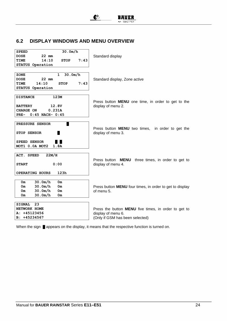
6.2 DISPLAY WINDOWS AND MENU OVERVIEW SPEED 30.0m/h DOSE 22 mm TIME 14:10 STOP 7:43 STATUS Operation
Standard display
ZONE 1 30.0m/h DOSE 22 mm TIME 14:10 STOP 7:43 STATUS Operation
Standard display, Zone active
DISTANCE 123M
BATTERY 12.8V CHARGE ON 0.231A PRE- 0:45 NACH- 0:45
Press button MENU one time, in order to get to the display of menu 2.
PRESSURE SENSOR █
STOP SENSOR █
SPEED SENSOR █ █ MOT1 0.0A MOT2 1.8A
Press button MENU two times, in order to get the display of menu 3.
ACT. SPEED 22M/H
START 0:00 OPERATING HOURS 123h
Press button MENU three times, in order to get to display of menu 4.
0m 30.0m/h 0m 0m 30.0m/h 0m 0m 30.0m/h 0m 0m 30.0m/h 0m
Press button MENU four times, in order to get to display of menu 5.
SIGNAL 23 NETWORK HOME A: +45123456 B: +45234567
Press the button MENU five times, in order to get to display of menu 6. (Only if GSM has been selected)
When the sign █ appears on the display, it means that the respective function is turned on.
Manual for BAUER RAINSTAR series E11–E51 25
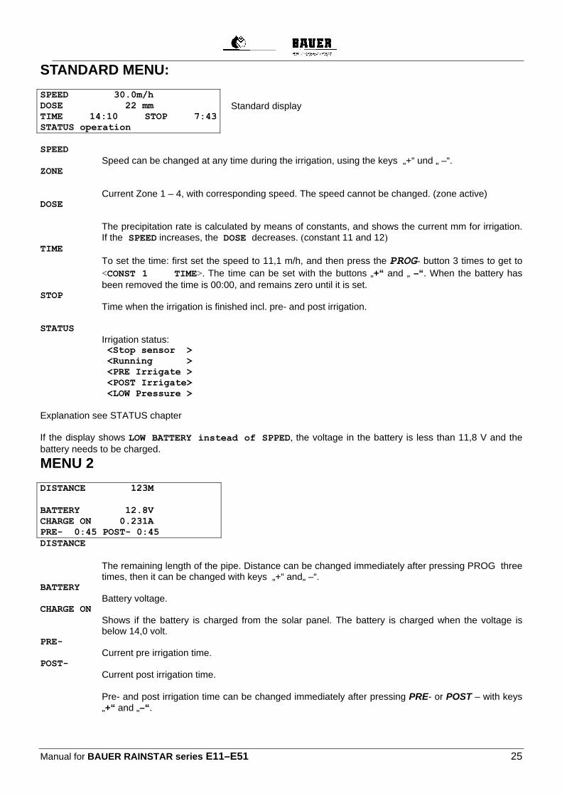
STANDARD MENU:
SPEED 30.0m/h DOSE 22 mm TIME 14:10 STOP 7:43 STATUS operation
Standard display
SPEED
Speed can be changed at any time during the irrigation, using the keys „+“ und „ –“. ZONE
Current Zone 1 – 4, with corresponding speed. The speed cannot be changed. (zone active) DOSE
The precipitation rate is calculated by means of constants, and shows the current mm for irrigation. If the SPEED increases, the DOSE decreases. (constant 11 and 12)
TIME To set the time: first set the speed to 11,1 m/h, and then press the PROG- button 3 times to get to <CONST 1 TIME>. The time can be set with the buttons „+“ and „ –“. When the battery has been removed the time is 00:00, and remains zero until it is set.
STOP Time when the irrigation is finished incl. pre- and post irrigation.
STATUS
Irrigation status: <Stop sensor > <Running >
<PRE Irrigate > <POST Irrigate> <LOW Pressure >
Explanation see STATUS chapter If the display shows LOW BATTERY instead of SPPED, the voltage in the battery is less than 11,8 V and the battery needs to be charged.
MENU 2
DISTANCE 123M
BATTERY 12.8V CHARGE ON 0.231A PRE- 0:45 POST- 0:45 DISTANCE
The remaining length of the pipe. Distance can be changed immediately after pressing PROG three times, then it can be changed with keys „+“ and„ –“.
BATTERY Battery voltage.
CHARGE ON Shows if the battery is charged from the solar panel. The battery is charged when the voltage is below 14,0 volt.
PRE- Current pre irrigation time.
POST- Current post irrigation time. Pre- and post irrigation time can be changed immediately after pressing PRE- or POST – with keys „+“ and „–“.

Manual for BAUER RAINSTAR Series E11–E51 26
MENU 3
PRESS SENSOR █
STOP SENSOR █
SPEED SENSOR █ █ MOT1 0.0A MOT2 1.8A
PRESS SENSOR
Shows if the pressure is high.The marker is on when the water pressure is high. The machine can only work when the pressure is high.
STOP SENSOR Shows if the stop switch is activated. The marker is on when the stop switch is on. The machine can only work when the stop switch is on. The stop switch has three functions:
1: Resets the distance counter 2: Post-irrigation 3: Inhibits the pulses to the regulating motor.
SPEED SENSOR Test speed sensor. The marker is on when the magnates activate the speed sensor.
MOT1, MOT2 Shows the current power consumption of the motor. The motor is stopped when the power consumption exceeds 4,5 A. If the power consumption exceeds 4,5 A, and the motor has not reached its end position the shut off valve is blocked.
MENU 4
ACTUAL SPEED 22M/H
START 0:00 WORKING HOURS 123h ACTUAL SPEED
Shows the current speed of the machine. Furthermore, the maximum running speed of the machine can be checked if the ECOSTAR 4300 is set to a much higher speed than the machine can run. The current speed can differ from the set speed, especially at the start. This is not an error because the ECOSTAR 4300 ensures that the medium speed over a distance of 10 m is correct.
START With this function the starting time of the machine can be delayed for up to 24 hours. To set the start time press „PROG“-key three times and the time can be set with the keys „+“ and „–“.
WORKING HOURS
The total working hour since the electronic was started for the first time.
Manual for BAUER RAINSTAR series E11–E51 27
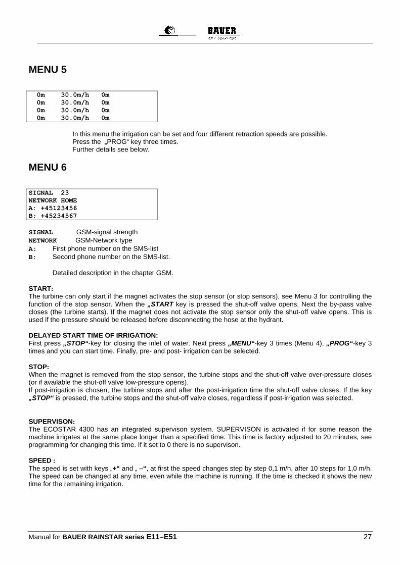
MENU 5
0m 30.0m/h 0m 0m 30.0m/h 0m 0m 30.0m/h 0m 0m 30.0m/h 0m
In this menu the irrigation can be set and four different retraction speeds are possible. Press the „PROG“ key three times. Further details see below.
MENU 6
SIGNAL 23 NETWORK HOME A: +45123456 B: +45234567 SIGNAL GSM-signal strength NETWORK GSM-Network type A: First phone number on the SMS-list B: Second phone number on the SMS-list. Detailed description in the chapter GSM. START: The turbine can only start if the magnet activates the stop sensor (or stop sensors), see Menu 3 for controlling the function of the stop sensor. When the „START key is pressed the shut-off valve opens. Next the by-pass valve closes (the turbine starts). If the magnet does not activate the stop sensor only the shut-off valve opens. This is used if the pressure should be released before disconnecting the hose at the hydrant. DELAYED START TIME OF IRRIGATION: First press „STOP“-key for closing the inlet of water. Next press „MENU“-key 3 times (Menu 4), „PROG“-key 3 times and you can start time. Finally, pre- and post- irrigation can be selected. STOP: When the magnet is removed from the stop sensor, the turbine stops and the shut-off valve over-pressure closes (or if available the shut-off valve low-pressure opens). If post-irrigation is chosen, the turbine stops and after the post-irrigation time the shut-off valve closes. If the key „STOP“ is pressed, the turbine stops and the shut-off valve closes, regardless if post-irrigation was selected. SUPERVISON: The ECOSTAR 4300 has an integrated supervison system. SUPERVISON is activated if for some reason the machine irrigates at the same place longer than a specified time. This time is factory adjusted to 20 minutes, see programming for changing this time. If it set to 0 there is no supervison. SPEED : The speed is set with keys „+“ and „ –“, at first the speed changes step by step 0,1 m/h, after 10 steps for 1,0 m/h. The speed can be changed at any time, even while the machine is running. If the time is checked it shows the new time for the remaining irrigation.

Manual for BAUER RAINSTAR Series E11–E51 28
PRE-IRRIGATION: Pressing the key PRE- can activate pre-irrigation. The time for pre-irrigation is calculated by the ECOSTAR 4300 as 8 x the time for running 1 meter with the current speed. The constant „8“ (constant no. 2) can be changed, see programming. If the pre-irrigation is on the machine starts and runs 1/2 pm enter and then it stops for the pre-irrigation time. By pressing the key „START“ the pre-irrigation is cancelled. The magnet at the stop sensor should be in place, before activating the pre-irrigation. POST-IRRIGATION: The post-irrigation can be activated by pressing the key „POST-“. The time for post-irrigation is calculated by the ECOSTAR 4300 as 8 x the time for running 1 meter the current speed. The constant „8“ (constant no.3) can be changed, see programming. The post-irrigation starts to count down when the magnet is removed from the stop sensor. When the magnet is removed, the motor for speed regulation stops the turbine. After the post-irrigation time the shut-off valve closes ( or opens, is available, the valve low pressure) At machines with only one motor for speed regulation the turbine starts after the post-irrigation. By pressing the key „START“ the post irrigation is cancelled. The magnet at the stop sensor should be in place before activating the post-irrigation. If the constant no.8 “early stop” is selected, this function is activated. The machine shuts down if the distance is reached. PROGRAMMING OF 4 DIFFERENT SPEEDS Display must show menu 5. The pipe should be pulled out before programming, so the computer can calculate the distance of the field to be irrigated. In the following example the length of the field to be irrigated is 400 m. Press the „PROG“-Key 3 x. The display shows. 400m 30.0m/h 0m 0m 30.0m/h 0m 0m 30.0m/h 0m 0m 30.0m/h 0m
The desired speed can now be set, here 25,0 m/h. Then press the „PROG“-key 1 x. The display shows: 400m 25.0m/h 0m 0m 30.0m/h 0m 0m 30.0m/h 0m 0m 30.0m/h 0m The desired distance can now be set, here 300 m. Then press the „PROG“-key 1 x. The display shows: 400m 25.0m/h 300m 300m 30.0m/h 0m 0m 30.0m/h 0m 0m 30.0m/h 0m
Now the first zone is programmed and the procedure is continued for all 4 zones. Zone 4 automatically ends at 000m. When zone 4 is programmed press again the „PROG“-key. The display shows: DLETE MENU PRESS SAVE PROG PRESS By pressing the key “PROG“- the program is saved and the irrigation is carried out according to the program. By pressing the key „MENU“-the program is deleted and the speed stays the same for the whole field.
Manual for BAUER RAINSTAR series E11–E51 29
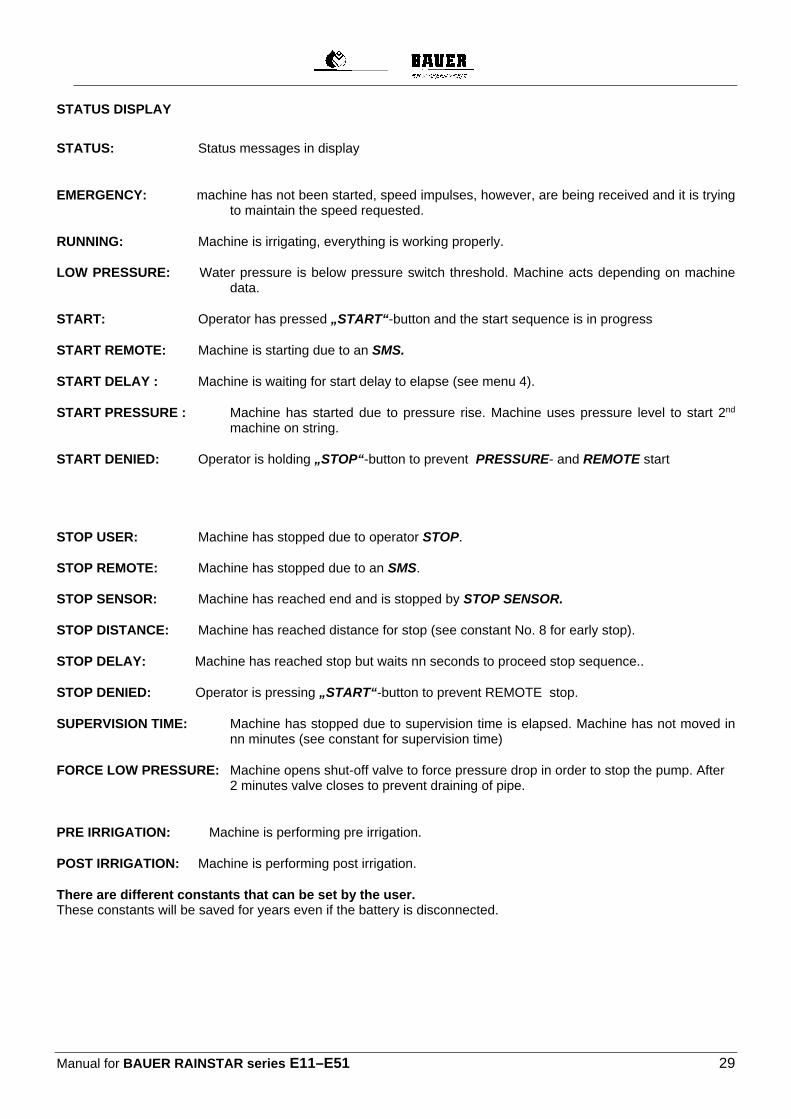
STATUS DISPLAY
STATUS: Status messages in display EMERGENCY: machine has not been started, speed impulses, however, are being received and it is trying
to maintain the speed requested. RUNNING: Machine is irrigating, everything is working properly. LOW PRESSURE: Water pressure is below pressure switch threshold. Machine acts depending on machine
data. START: Operator has pressed „START“-button and the start sequence is in progress START REMOTE: Machine is starting due to an SMS. START DELAY : Machine is waiting for start delay to elapse (see menu 4). START PRESSURE : Machine has started due to pressure rise. Machine uses pressure level to start 2nd
machine on string. START DENIED: Operator is holding „STOP“-button to prevent PRESSURE- and REMOTE start STOP USER: Machine has stopped due to operator STOP. STOP REMOTE: Machine has stopped due to an SMS. STOP SENSOR: Machine has reached end and is stopped by STOP SENSOR. STOP DISTANCE: Machine has reached distance for stop (see constant No. 8 for early stop). STOP DELAY: Machine has reached stop but waits nn seconds to proceed stop sequence.. STOP DENIED: Operator is pressing „START“-button to prevent REMOTE stop. SUPERVISION TIME: Machine has stopped due to supervision time is elapsed. Machine has not moved in
nn minutes (see constant for supervision time) FORCE LOW PRESSURE: Machine opens shut-off valve to force pressure drop in order to stop the pump. After
2 minutes valve closes to prevent draining of pipe.
PRE IRRIGATION: Machine is performing pre irrigation. POST IRRIGATION: Machine is performing post irrigation. There are different constants that can be set by the user. These constants will be saved for years even if the battery is disconnected.
Manual for BAUER RAINSTAR Series E11–E51 30
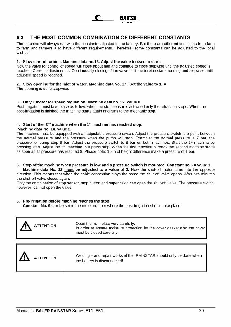
6.3 THE MOST COMMON COMBINATION OF DIFFERENT CONSTANTS The machine will always run with the constants adjusted in the factory. But there are different conditions from farm to farm and farmers also have different requirements. Therefore, some constants can be adjusted to the local wishes. 1. Slow start of turbine. Machine data no.13. Adjust the value to 4sec to start. Now the valve for control of speed will close about half and continue to close stepwise until the adjusted speed is reached. Correct adjustment is: Continuously closing of the valve until the turbine starts running and stepwise until adjusted speed is reached. 2. Slow opening for the inlet of water. Machine data No. 17 . Set the value to 1. = The opening is done stepwise. 3. Only 1 motor for speed regulation. Machine data no. 12. Value 0 Post-irrigation must take place as follow: when the stop sensor is activated only the retraction stops. When the post-irrigation is finished the machine starts again and runs to the mechanic stop. 4. Start of the 2nd machine when the 1st machine has reached stop. Machine data No. 14. value 2. The machine must be equipped with an adjustable pressure switch. Adjust the pressure switch to a point between the normal pressure and the pressure when the pump will stop. Example: the normal pressure is 7 bar, the pressure for pump stop 9 bar. Adjust the pressure switch to 8 bar on both machines. Start the 1st machine by pressing start. Adjust the 2nd machine, but press stop. When the first machine is ready the second machine starts as soon as its pressure has reached 8. Please note: 10 m of height difference make a pressure of 1 bar. 5. Stop of the machine when pressure is low and a pressure switch is mounted. Constant no.6 = value 1 Machine data No. 12 must be adjusted to a value of 2. Now the shut-off motor turns into the opposite direction. This means that when the cable connection stays the same the shut-off valve opens. After two minutes the shut-off valve closes again. Only the combination of stop sensor, stop button and supervision can open the shut-off valve. The pressure switch, however, cannot open the valve. 6. Pre-irrigation before machine reaches the stop Constant No. 9 can be set to the meter number where the post-irrigation should take place.
Open the front plate very carefully. In order to ensure moisture protection by the cover gasket also the cover must be closed carefully!
Welding – and repair works at the RAINSTAR should only be done when
the battery is disconnected!
ATTENTION!
ATTENTION!
Manual for BAUER RAINSTAR series E11–E51 31
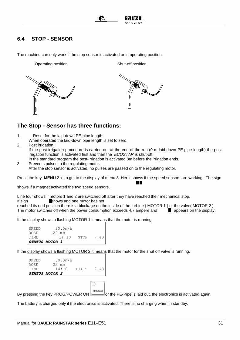
6.4 STOP - SENSOR The machine can only work if the stop sensor is activated or in operating position.
Operating position Shut-off position
The Stop - Sensor has three functions: 1. Reset for the laid-down PE-pipe length: When operated the laid-down pipe length is set to zero. 2. Post irrigation:
If the post-irrigation procedure is carried out at the end of the run (0 m laid-down PE-pipe length) the post-irrigation function is activated first and then the ECOSTAR is shut-off.
In the standard program the post-irrigation is activated 8m before the irrigation ends. 3. Prevents pulses to the regulating motor. After the stop sensor is activated, no pulses are passed on to the regulating motor. Press the key MENU 2 x, to get to the display of menu 3. Her it shows if the speed sensors are working . The sign shows if a magnet activated the two speed sensors. Line four shows if motors 1 and 2 are switched off after they have reached their mechanical stop. If sign shows and one motor has not reached its end position there is a blockage on the inside of the turbine ( MOTOR 1 ) or the valve( MOTOR 2 ). The motor switches off when the power consumption exceeds 4,7 ampere and appears on the display. If the display shows a flashing MOTOR 1 it means that the motor is running
SPEED 30.0m/h DOSE 22 mm TIME 14:10 STOP 7:43STATUS MOTOR 1
If the display shows a flashing MOTOR 2 it means that the motor for the shut off valve is running.
SPEED 30.0m/h DOSE 22 mm TIME 14:10 STOP 7:43STATUS MOTOR 2
By pressing the key PROG/POWER ON or the PE-Pipe is laid out, the electronics is activated again. The battery is charged only if the electronics is activated. There is no charging when in standby.

Manual for BAUER RAINSTAR Series E11–E51 32
6.5 OPERATION OF THE BAUER ECOSTAR 4300 Summary: Pull off or lay down the PE – pipe Connect water supply Engage gearbox
ECOSTAR: make settings only in the standard menu: Take over retraction speed from the last retraction or set again.
Press "START-RESET“ key Activate pre-irrigation if required Activate post-irrigation if required Open water inlet Irrigation runs automatically
FURTHER OPERATING INSTRUCTIONS After a longer standstill the electronic system of the ECOSTAR 4300 is on standby. Pulling off or laying down the PE – pipe activates the electronic system and the length of the pulled off or laid down pipe is metered. For display of laid out PE-pipe, press key Menu 1 x: DISTANCE 123M
BATTERY 12.8V CHARGE ON 0.231A PRE- 0:45 POST- 0:45

Manual for BAUER RAINSTAR series E11–E51 33
6.5.1 SPEED ADJUSTMENT The pre-adjusted speed of 30 m/h can be increases or decreased with the arrow keys
. At first the speed changes step by step for 0,1 m/h, then after ten steps there is a change of 1,0 m/h. The speed can be changed at anytime while the machine is running. The remaining time until the end of irrigation is also changed. The speed cannot be changed while one of the servo motor for the turbine regulation or shut-off valve is running. The display shows MOTOR 1 or MOTOR 2. When changing the speed also the corresponding time changes. SPEED 30.0m/h DOSE 22 mm TIME 14:10 STOP 7:43 STATUS OPERATION
When setting the speed it is necessary to check on the speed that is actually possible according to the test window (press menu key 3 x).
In case of variation the set speed must be reduced to the speed that is actually
possible.
6.5.2 PRE – OR POST IRRIGATION
With the keys PRE – or. POST IRRIGATION these functions can be activated. The time for the pre- and post is pre-programmed and is calculated by the ECOSTAR 4300 as 8 times the time for covering a distance of 1 meter with the actual speed. e.g: for vE = 20 m/h there is a time of 3 min for 1 m retraction This makes a pre-irrigation time of 8 x 3 min = 24 min and a post irrigation time of also 8 x 3 min = 24 min This value “8” can be changed in the program (program constant No 2 and No 3) – See parameter sheet 1: constants. If the pre irrigation function is activated, the machine runs approx. ½ meter after the start and then stands still for the pre irrigation time.
Important!

Manual for BAUER RAINSTAR Series E11–E51 34
When pressing the button “START-RESET” , during pre-irrigation the pre-irrigation function is deleted.
Before activating the pre-irrigation mode the PE – pipe should be pulled off (the shut-off frame and thus also the shut-off sensor should be in the operating status) and the “START-RESET” key should have been pressed. If the post-irrigation mode is activated the machine stops 8m before the end of the run for the post-irrigation time. This value is pre-adjusted and can be changed in the program constant no.9, see parameter sheet 1: constants.
If you press the key “START-RESET” , the post irrigation is cancelled.
6.5.3 START If the PE – pipe has been pulled off and the desired speed has been set you can start the irrigation with the
“START–RESET“ key.
If pre- or post- irrigation is required, press the following keys The turbine can only start if the shut-off frame and thus also the shut-off sensor are in the operating state (PE-pipe pulled off). If the „START–RESET“ key is pressed the turbine flap closes, the tooth segment on the regulating motor rotates to the limiting bolt head and the shut-off valve (if existing-optional) opens.

Manual for BAUER RAINSTAR series E11–E51 35
6.5.4 MONITORING The program has a built-in monitoring system. It only works in connection with the shut-off valve- overpressure. The standard factory setting of the monitoring is 20min. (parameter sheet 1, machine data 4). In this mode monitoring will start if the RAINSTAR does not reach the set speed within the programmed monitoring time. After this time the shut-off valve is closed and the machine stops. In most cases the reasons are excessively high retraction speeds or a blocked regulation flap etc. In order to ensure that the set retraction speed is actually reached and the system is not switched off after the monitoring time, it is necessary to check the retraction speed that is actually possible by pressing the menu key three times. If the system is equipped with a pressure switch the machine will start when a preset minimum pressure is reached, or it stops irrigating when water pressure is too low. As soon as the pressure returns to normal level, irrigation is continued.
6.5.5 STOP At the end of the irrigation run the shut-off sensor is activated through shut-off frame and shut-off rods.
Sensor in shut-off position
As a result the turbine stops and the shut-off valve overpressure closes slowly and remains in this position until the next operation. If the RAINSTAR is connected to a hydrant you can release the water pressure which is remaining in the line after
closing the hydrant by pushing the „START-RESET“ key. The shut-off valve opens and pressure is released through the PE-pipe. If a low-pressure shut-off valve is mounted, it opens quickly. It closes again after approx. 15 min.
By pressing the key „STOP“ the irrigation process can be stopped at any time. The turbine flap opens (the turbine stops), the over-pressure shut-off valve closes, the low-pressure shut-off valve opens. The laid down PE – pipe length remains saved. It is set to 000 only when the shut-off sensor is actuated ( shut-off position).
ATTENTION ! If the „STOP“ key is used while retraction on a machine without shut-off valve the retraction stops but the sprinkler is still in operation. In order to prevent “over irrigation” around the sprinkler the machine should only work for a limited period of time without retraction. Then start the machine again by pressing the„START“ key!!
Manual for BAUER RAINSTAR Series E11–E51 36
ATTENTION ! With machine data adjustments Pos. 12, adjustment „0“, the retraction stops only for a short period of time when pressing „STOP“ key. After a few seconds the retraction starts again automatically. ATTENTION: when working on the machine the whole drive needs to be switched off!!
STOPPING THE CONTROL FUNCTIONS, By pressing the keys „STOP“ and „PROG.“ at the same time all functions of the ECOSTAR stop, this means that the regulating motors of the turbine and the shut-off valve remain in their current position. With this combination of keys the turbine regulation is stopped when the turbine rotation speed is low in order to change gears.
6.6 PRESSURE SWITCH ( OPTIONAL EQUIPMENT) If the RAINSTAR, after having been positioned for the run, is supposed to start-up only after the required pressure has built up in the supply line (Pressure start) a pressure switch must be installed. If such a switch is available, the monitoring system will also interrupt the irrigation cycle in case of low water pressure. As soon as the pressure returns to normal the irrigation is continued.
IMPORTANT: the pressure switch should only be used together with a shut-off valve over pressure!!
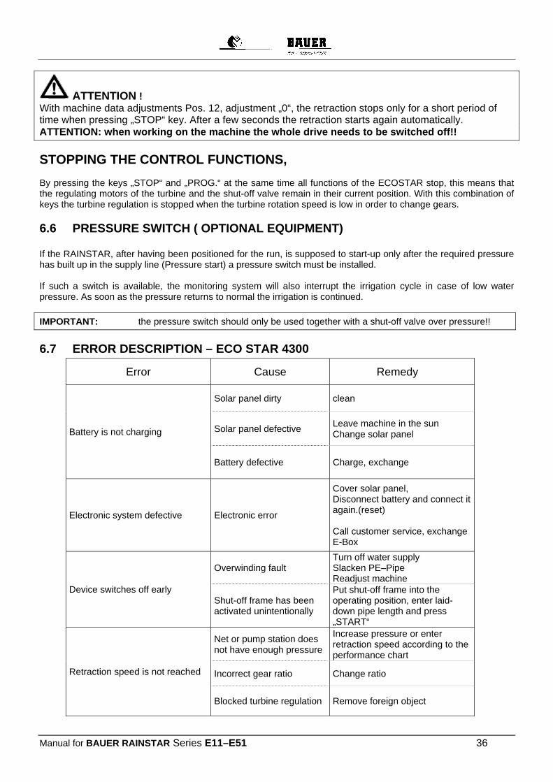
6.7 ERROR DESCRIPTION – ECO STAR 4300
Error Cause Remedy
Battery is not charging
Solar panel dirty clean
Solar panel defective Leave machine in the sun Change solar panel
Battery defective Charge, exchange
Electronic system defective Electronic error
Cover solar panel, Disconnect battery and connect it again.(reset) Call customer service, exchange E-Box
Device switches off early
Overwinding fault Turn off water supply Slacken PE–Pipe Readjust machine
Shut-off frame has been activated unintentionally
Put shut-off frame into the operating position, enter laid-down pipe length and press „START“
Retraction speed is not reached
Net or pump station does not have enough pressure
Increase pressure or enter retraction speed according to the performance chart
Incorrect gear ratio Change ratio
Blocked turbine regulation Remove foreign object

Manual for BAUER RAINSTAR series E11–E51 37
6.8 PROGRAMMING PROCEDURE The electronic system is factory-programmed. However, if site conditions require settings which deviate from these data it is possible to modify the program constants and machine data accordingly. Proceed as follows: In order to reach the constants the speed must be set at 11,1 m/h or 11f/h
Immediately press the “PROGRAMM”-key three times in order to get to program constant 0 ( see parameter sheet No. 1 ) By pressing the “PROGRAM”-key again shortly to select constant numbers 01 – 12 see parameter sheet No. 1.
With the arrow keys the values can be changed according to the requirements.
If you press the “MENU” key the changed constants are saved and the program returns to the standard display. If you do not press “MENU” the changes are not saved and the program returns to the standard display after one minute. The constants remain saved, even if the battery is disconnected for a longer time. The program constant 0 with the value 111 gives access to the machine data.
By pressing the key PROGRAM you can access the machine data mode. See parameter sheet No. 2 By pressing the “PROGRAMM”-key again the machine data numbers 0 – 19 are selected. With the arrow keys the values can be changed according to the requirements. By pressing the key “MENU” the program returns to the standard display and saves the changed machine data. If the key „MENU“ is not pressed the ECOSTAR 4300 returns to normal mode after one minute and the adjustments of the constants are not saved.
Manual for BAUER RAINSTAR Series E11–E51 38
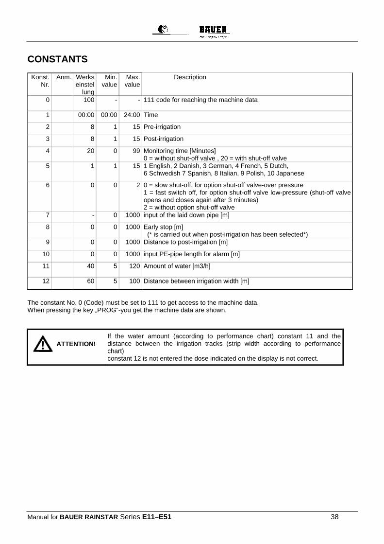
CONSTANTS
Konst.
Nr. Anm. Werks
einstellung
Min. value
Max. value
Description
0 100 - - 111 code for reaching the machine data
1 00:00 00:00 24:00 Time
2 8 1 15 Pre-irrigation
3 8 1 15 Post-irrigation
4 20 0 99 Monitoring time [Minutes] 0 = without shut-off valve , 20 = with shut-off valve
5 1 1 15 1 English, 2 Danish, 3 German, 4 French, 5 Dutch, 6 Schwedish 7 Spanish, 8 Italian, 9 Polish, 10 Japanese
6 0 0 2 0 = slow shut-off, for option shut-off valve-over pressure 1 = fast switch off, for option shut-off valve low-pressure (shut-off valve opens and closes again after 3 minutes) 2 = without option shut-off valve
7 - 0 1000 input of the laid down pipe [m]
8 0 0 1000 Early stop [m] (* is carried out when post-irrigation has been selected*)
9 0 0 1000 Distance to post-irrigation [m]
10 0 0 1000 input PE-pipe length for alarm [m]
11 40 5 120 Amount of water [m3/h]
12 60 5 100 Distance between irrigation width [m]
The constant No. 0 (Code) must be set to 111 to get access to the machine data. When pressing the key „PROG“-you get the machine data are shown.
If the water amount (according to performance chart) constant 11 and the distance between the irrigation tracks (strip width according to performance chart) constant 12 is not entered the dose indicated on the display is not correct.
ATTENTION!
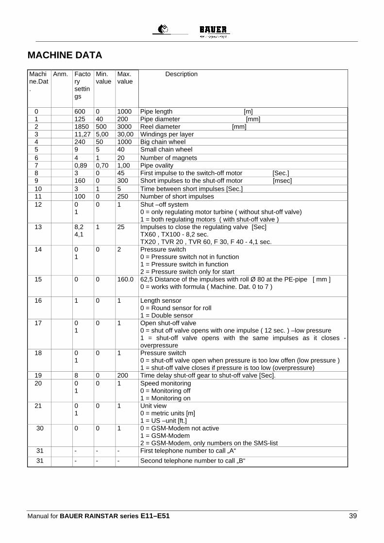
Manual for BAUER RAINSTAR series E11–E51 39
MACHINE DATA Machine.Dat.
Anm. Factory settings
Min. value
Max. value
Description
0 600 0 1000 Pipe length [m] 1 125 40 200 Pipe diameter [mm] 2 1850 500 3000 Reel diameter [mm] 3 11,27 5,00 30,00 Windings per layer 4 240 50 1000 Big chain wheel 5 9 5 40 Small chain wheel 6 4 1 20 Number of magnets 7 0,89 0,70 1,00 Pipe ovality 8 3 0 45 First impulse to the switch-off motor [Sec.] 9 160 0 300 Short impulses to the shut-off motor [msec] 10 3 1 5 Time between short impulses [Sec.] 11 100 0 250 Number of short impulses 12 0
1 0 1 Shut –off system
0 = only regulating motor turbine ( without shut-off valve) 1 = both regulating motors ( with shut-off valve )
13 8,2 4,1
1 25 Impulses to close the regulating valve [Sec] TX60 , TX100 - 8,2 sec. TX20 , TVR 20 , TVR 60, F 30, F 40 - 4,1 sec.
14 0 1
0 2 Pressure switch 0 = Pressure switch not in function 1 = Pressure switch in function 2 = Pressure switch only for start
15 0 0 160.0 62,5 Distance of the impulses with roll Ø 80 at the PE-pipe [ mm ] 0 = works with formula ( Machine. Dat. 0 to 7 )
16 1 0 1 Length sensor 0 = Round sensor for roll 1 = Double sensor
17 0 1
0 1 Open shut-off valve 0 = shut off valve opens with one impulse ( 12 sec. ) –low pressure 1 = shut-off valve opens with the same impulses as it closes -overpressure
18 0 1
0 1 Pressure switch 0 = shut-off valve open when pressure is too low offen (low pressure ) 1 = shut-off valve closes if pressure is too low (overpressure)
19 8 0 200 Time delay shut-off gear to shut-off valve [Sec]. 20 0
1 0 1 Speed monitoring
0 = Monitoring off 1 = Monitoring on
21 0 1
0 1 Unit view 0 = metric units [m] 1 = US –unit [ft.]
30 0 0 1 0 = GSM-Modem not active 1 = GSM-Modem 2 = GSM-Modem, only numbers on the SMS-list
31 - - - First telephone number to call „A“
31 - - - Second telephone number to call „B“
Manual for BAUER RAINSTAR Series E11–E51 40
6.9 BATTERY In the factory a battery of 12 V and 6,5 ampere hours is mounted. Charging the battery with a standard solar panel during the irrigation season is not necessary. Basically, the battery should be charged all 6 month with a charging current of max. 2 ampere. (Please note the maintenance and operating manual).
If the battery is connected the display shows for a short time e.g. “VERSION 4.1”, and then goes over to standard
display again. In order to ensure a long lifespan of the dry battery of the ECOSTAR (LC-R 127R2PG 7,2 Ah/20 HR), it is important to follow certain guidelines when storing and charging the device. During operation of the battery on the ECOSTAR no special precautions need to be taken as the solar panel permanently charges the battery. 1. Every new RAINSTAR irrigation machine delivered by BAUER, which is equipped with an ECOSTAR is also
equipped with a fully charged and ready to use battery. The solar panel,however, is covered and not connected to the battery. If there is a longer period of time between delivery and first operation the battery needs to be maintained. (see following points) The same applies for spare part batteries and batteries which were held on stock for a longer period of time.
2. If the RAINSTAR is not in operation for a longer period of time, e.g off season, the battery should be disconnected from the ECOSTAR and dismounted.
3. The accumulator battery should be stored fully charged, separate of conductive materials and out of the sun. If the accumulator battery is stored in an uncharged condition for a longer period of time the full capacity cannot be reached again after charging.
4. The optimum storage temperature lies between 0° and +25°. Also during storage the battery underlies self-discharge and needs to be charged in the following intervals: Storage temperature: Interval for charging: Less than +20°C 9 month +20°C to +30°C 6 month +30°C to +40°C 3 month
5. The humidity in the storage room needs to be low (55%+/- 30%) in order to prevent that the poles corrode. 6. A complete discharge of the battery should be prevented (deep discharge). The battery can be charged and
reach its full capacity again but a repeated deep discharge the lifespan of the battery is reduced. 7. The accumulator batteries should be kept clean. For cleaning a dry cloth can be used, if required soaked in
water or alcohol. Under no circumstances use oil, petrol or diluents.
8. Accumulator batteries must not be disassembled as they contain acid which can cause strong chemical burns. 9. Accumulator batteries must not be hot-wired as they could be damaged. 10. Charging the battery should be done with a voltage of max. 2,0 A. If the battery is fully discharged the battery
needs approx. 7 hours until is is fully charged. Devices which check the capacity of the battery, as well as devices with an intelligent (self-regulating) charging function, enable an exact analysis as well as a controlled charging of the battery.

Manual for BAUER RAINSTAR series E11–E51 41
6.9.1 SOLAR PANEL
In the factory a solar panel is mounted which is maintenance free.
1. In order to ensure optimal performance the surface should be cleaned from time to time with a soft cloth and
household cleaning agent ( no scrubbing agent). 2. For operation the solar panel is unfolded and blocked. The solar radiation on the panel is more intensive.
For transport of the RAINSTAR the panel is folded again. It is lifted and pressed to the machine and can be brought into its initial position where it is protected against damage.
3. In order to prevent over charging of the accumulator battery and a disturbance of the ECOSTAR, the electronic interrupts the charging process if the „STOP“ key is pressed or the accumulator battery is connected (When the machine is delivered the clamps are removed)
6.9.2 CHECKING THE CONNECTIONS
Press „START“ key. The regulating motor closes(the segment turns to the limiting bolt)
The shut-off valve overpressure opens. The shut-off valve low pressure remains closed.
Press „STOP“ key The regulating motor opens the turbine (the segment turns away from the limiting bolt) The shut-off valve overpressure closes The shut-off valve low pressure opens
6.9.3 CHECKING THE LENGTH SENSOR The magnet disc with 4 magnets is mounted on the drive shaft of the gear and rotates clockwise during retraction. By rotating the magnet disc clockwise the display for the laid down pipe needs to count from 0 m upwards. If the distance counter counts into the opposite direction then the speed sensor must be turned around in order that the cable connection is on top. Distance 1 - 3 mm between double sensor and magnet disc.
Speed sensor Cable connection at the bottom
Manual for BAUER RAINSTAR Series E11–E51 42
6.9.4 LIMIT STOP FOR TURBINES – REGULATING VALVE WITH ECOSTAR 4300 See point 6.5. The regulating area of the regulating valve of the turbine needs to be adjusted to the respective delivery rate. If the limit stop is not adjusted correctly it might happen that the turbine cannot be regulated, this means that the PE-pipe retraction happens with maximum speed. If the flow rate is reduced significantly the limiting bolt head needs to be adjusted again, as otherwise the retraction speed listed on the performance chart cannot be reached. You can see the required delivery rate on the performance chart fixed on the machine below the nozzle sizes.
6.9.5 SHORT CHECKLIST FOR ECOSTAR 4300 1. Check battery voltage (should be 12 V minimum)
a) Cover solar panel completely b) See battery voltage In test menu 1 (press MENU key once) c) If there is no or not enough power available (below 12 V), check battery, cable connections or fuses inside
the electronic box. 2. Check function of the sensors
a) Set test menu 2 (press MENU key twice) b) The display show indications for function control of the installed sensors , Motor 1 -Motor 2
3. Check length indicator of the laid down PE-pipe (press MENU key once )
a) Read out the pipe length of the laid down PE-pipe on the standard display and compare with the engraved length indication on the PE-pipe.
b) If it shows 000 m, or significpless than the length of the laid out pipe, you need to make settings. 4. Check of the mechanic transmission to the stop sensor. 5. Adjustment of the limiting bolt for the tooth segment of the regulating valve according to the chart
fixed on the machine.
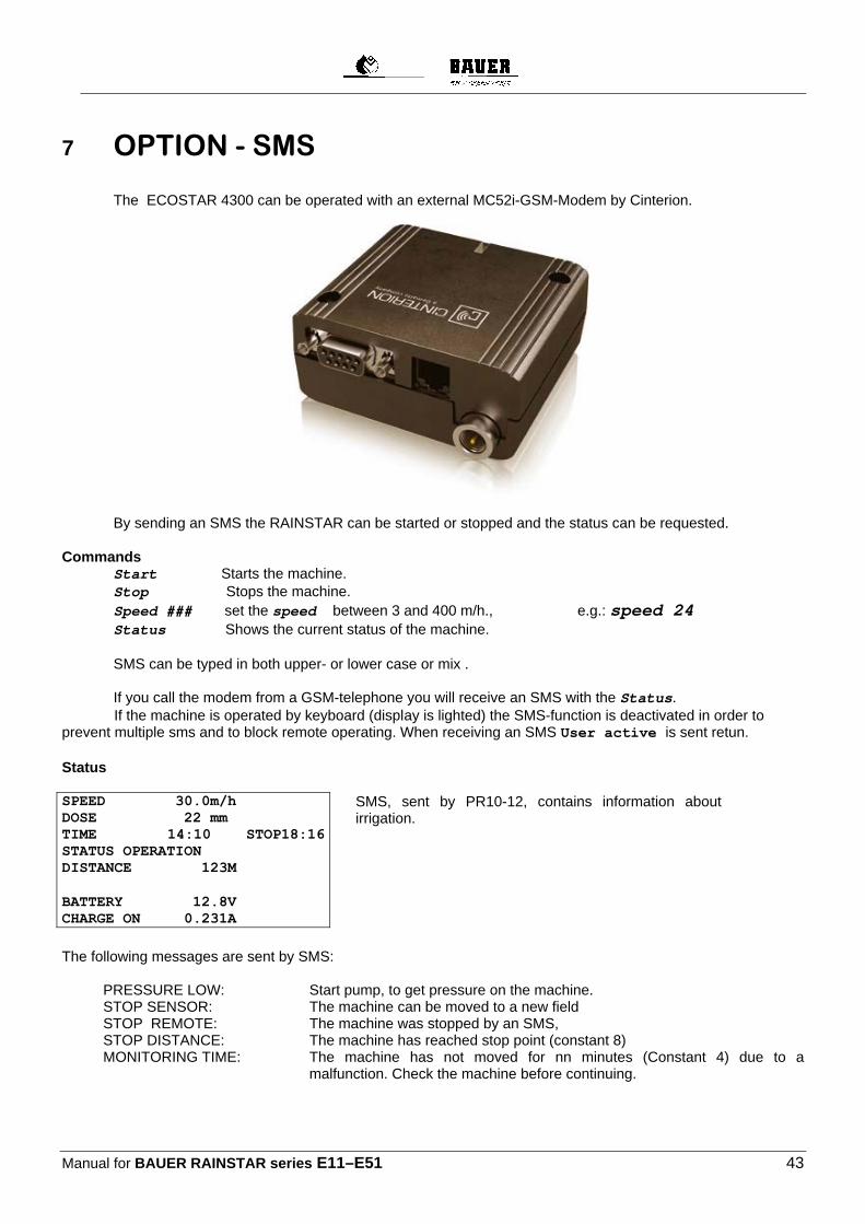
Manual for BAUER RAINSTAR series E11–E51 43
7 OPTION - SMS The ECOSTAR 4300 can be operated with an external MC52i-GSM-Modem by Cinterion.
By sending an SMS the RAINSTAR can be started or stopped and the status can be requested. Commands Start Starts the machine. Stop Stops the machine. Speed ### set the speed between 3 and 400 m/h., e.g.: speed 24 Status Shows the current status of the machine. SMS can be typed in both upper- or lower case or mix . If you call the modem from a GSM-telephone you will receive an SMS with the Status. If the machine is operated by keyboard (display is lighted) the SMS-function is deactivated in order to prevent multiple sms and to block remote operating. When receiving an SMS User active is sent retun. Status SPEED 30.0m/h DOSE 22 mm TIME 14:10 STOP18:16 STATUS OPERATION DISTANCE 123M
BATTERY 12.8V CHARGE ON 0.231A
SMS, sent by PR10-12, contains information about irrigation.
The following messages are sent by SMS: PRESSURE LOW: Start pump, to get pressure on the machine. STOP SENSOR: The machine can be moved to a new field STOP REMOTE: The machine was stopped by an SMS, STOP DISTANCE: The machine has reached stop point (constant 8) MONITORING TIME: The machine has not moved for nn minutes (Constant 4) due to a
malfunction. Check the machine before continuing.
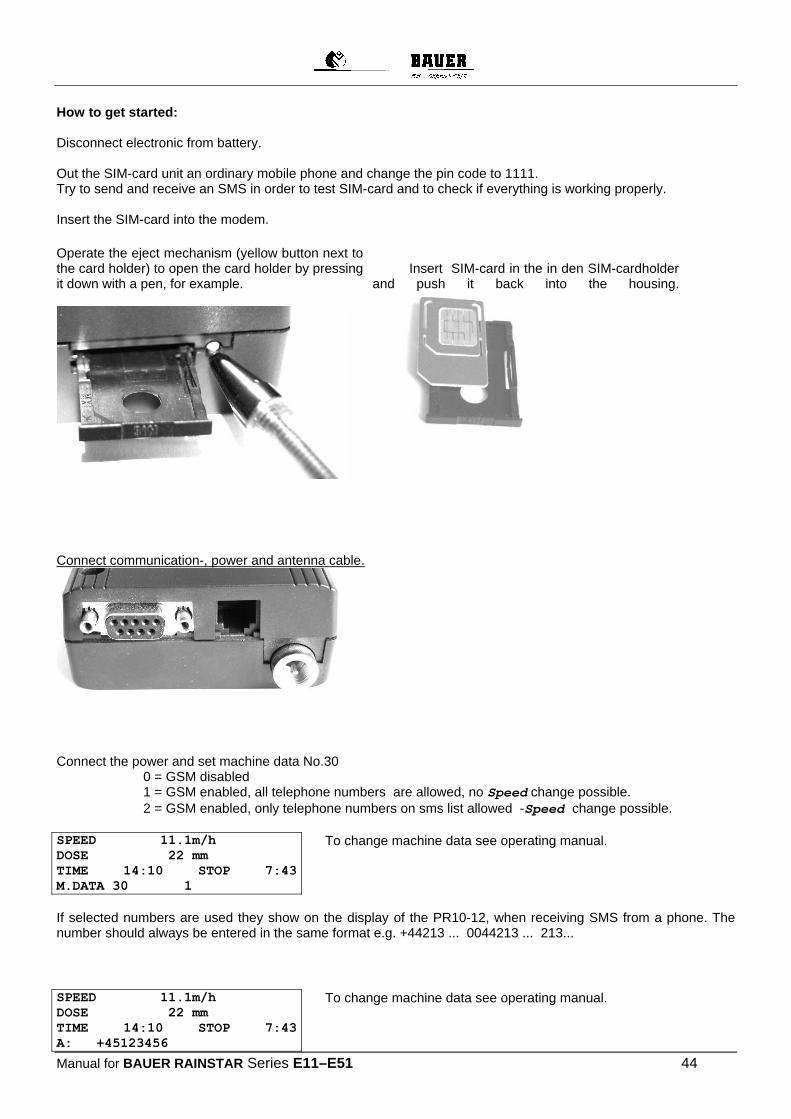
Manual for BAUER RAINSTAR Series E11–E51 44
How to get started: Disconnect electronic from battery. Out the SIM-card unit an ordinary mobile phone and change the pin code to 1111. Try to send and receive an SMS in order to test SIM-card and to check if everything is working properly. Insert the SIM-card into the modem. Operate the eject mechanism (yellow button next to the card holder) to open the card holder by pressing it down with a pen, for example.
Insert SIM-card in the in den SIM-cardholder and push it back into the housing.
Connect communication-, power and antenna cable.
Connect the power and set machine data No.30
0 = GSM disabled 1 = GSM enabled, all telephone numbers are allowed, no Speed change possible. 2 = GSM enabled, only telephone numbers on sms list allowed -Speed change possible.
SPEED 11.1m/h DOSE 22 mm TIME 14:10 STOP 7:43 M.DATA 30 1
To change machine data see operating manual.
If selected numbers are used they show on the display of the PR10-12, when receiving SMS from a phone. The number should always be entered in the same format e.g. +44213 ... 0044213 ... 213... SPEED 11.1m/h DOSE 22 mm TIME 14:10 STOP 7:43 A: +45123456
To change machine data see operating manual.
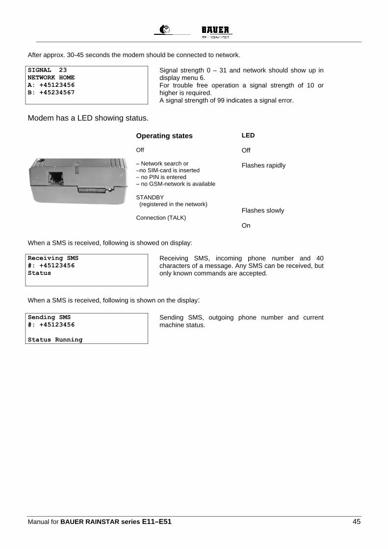
Manual for BAUER RAINSTAR series E11–E51 45
After approx. 30-45 seconds the modem should be connected to network. SIGNAL 23 NETWORK HOME A: +45123456 B: +45234567
Signal strength 0 – 31 and network should show up in display menu 6. For trouble free operation a signal strength of 10 or higher is required. A signal strength of 99 indicates a signal error.
Modem has a LED showing status.
Operating states Off – Network search or –no SIM-card is inserted – no PIN is entered – no GSM-network is available STANDBY (registered in the network) Connection (TALK)
LED Off Flashes rapidly Flashes slowly On
When a SMS is received, following is showed on display: Receiving SMS #: +45123456 Status
Receiving SMS, incoming phone number and 40 characters of a message. Any SMS can be received, but only known commands are accepted.
When a SMS is received, following is shown on the display: Sending SMS #: +45123456 Status Running
Sending SMS, outgoing phone number and current machine status.
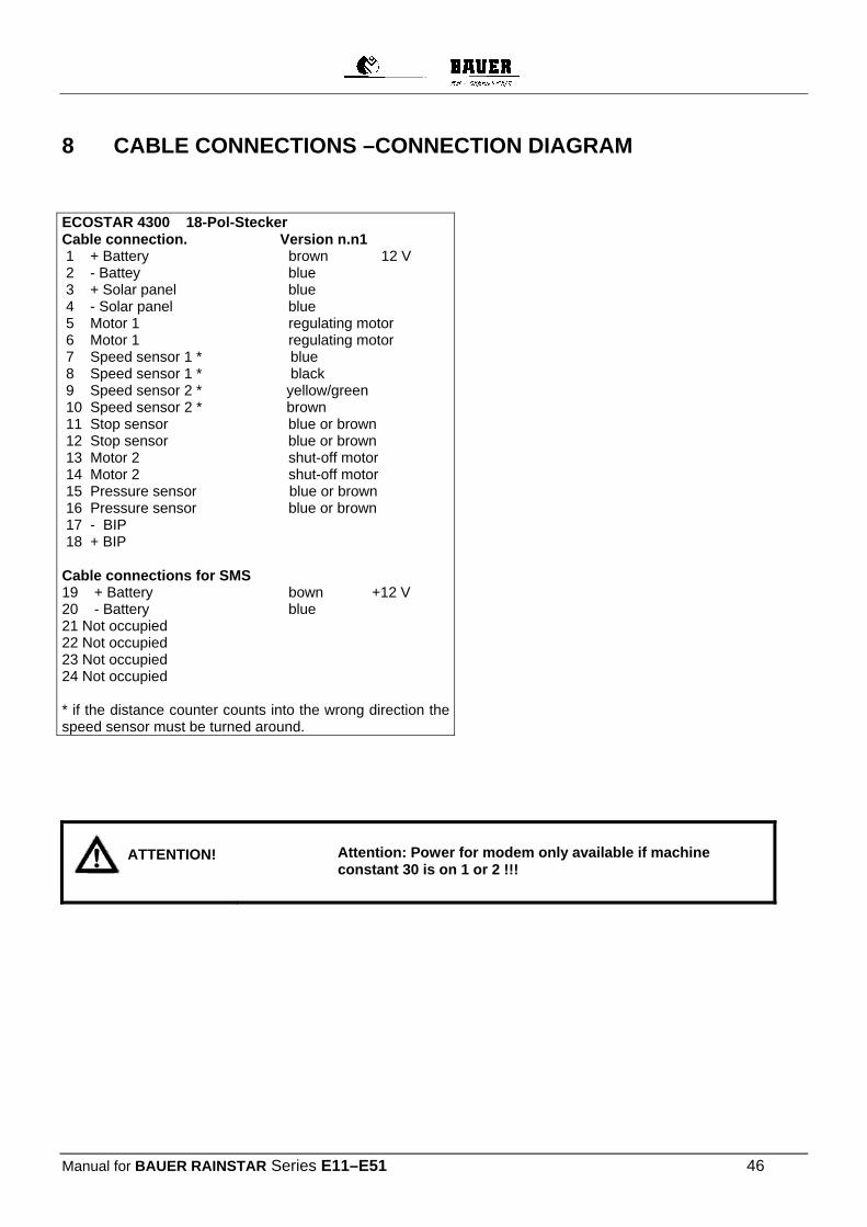
Manual for BAUER RAINSTAR Series E11–E51 46
8 CABLE CONNECTIONS –CONNECTION DIAGRAM
ECOSTAR 4300 18-Pol-Stecker Cable connection. Version n.n1 1 + Battery brown 12 V 2 - Battey blue 3 + Solar panel blue 4 - Solar panel blue 5 Motor 1 regulating motor 6 Motor 1 regulating motor 7 Speed sensor 1 * blue 8 Speed sensor 1 * black 9 Speed sensor 2 * yellow/green 10 Speed sensor 2 * brown 11 Stop sensor blue or brown 12 Stop sensor blue or brown 13 Motor 2 shut-off motor 14 Motor 2 shut-off motor 15 Pressure sensor blue or brown 16 Pressure sensor blue or brown 17 - BIP 18 + BIP Cable connections for SMS 19 + Battery bown +12 V 20 - Battery blue 21 Not occupied 22 Not occupied 23 Not occupied 24 Not occupied * if the distance counter counts into the wrong direction the speed sensor must be turned around.
Attention: Power for modem only available if machine constant 30 is on 1 or 2 !!!
ATTENTION!

Manual for BAUER RAINSTAR series E11–E51 47
COMMUNICATION
Communication between ECOSTAR 4300 and GSM modem
!!! Do not put pins into the coupler strip before the cable on the
ECOSTAR 4300 box is mounted!!!
1 not used 2 data reception brown 3 data transmission white 4 not used 5 mass yellow 6 not used 7 not used 8 not used 9 not used
View of connector holes for pin insertion (shows pin numbers)
Antenna
The antenna providing signal for GSM modem, should be placed in a way it provides good signal under all conditions.

Manual for BAUER RAINSTAR Series E11–E51 48
8.1.1 CHECKLIST FOR ECOSTAR 4300
During the first run at the start of the season, but also during normal operation, there can occur problems with the ECOSTAR, like negative reports, malfunction in connection with the electronics or the connected sensors, as well as problems due to operating errors. A systematic check of the system according to the checklist below can help to identify and solve the problem quickly. This checklist serves as an additional help to the detailed operating manual of the ECOSTAR 4300. After checking the device according to the SHORT-CHECKLIST, handling instructions are in the list below.
Po
s.
Error Check and find cause Remedy
1. Wrong or incomplete display signal
Check battery voltage! 1. The solar panel has to be covered completely and after 2-3 min
the battery voltage can be checked on the display of the first menu window. (Press menu key 1x) Note !
If the solar panel is not covered even an empty battery can show voltage on the display, or when the sun is shining a sufficient operating voltage is simulated. The power supply, however, is not sufficient for the system operation.
2. If the voltage of the battery (not influenced by the covered solar panel) is below 12V, the power supply for the operation of the system is not sufficient.
Charge or renew battery
2. Display not working
Check battery, cable connections and fuse! 1. Check battery voltage, battery is empty
2. The connection cables between battery and ECOSTAR are not
connected or without contact.
3. The fuse is defective. The fuse is inside the electronic box where you can find a replacement fuse.
Note ! When checking the connections it is important that the cables are
connected correctly: „+“ clamp = brown wire, „-“ clamp = blue wire. While disconnecting and connecting the battery and while the
battery is disconnected the solar panel should also be covered, as an indication error is possible.
The saved machine data remain saved when the battery remains connected.
When connecting the battery again you must not mistake the „Plus“ and „Minus“ clamps, as a short circuit is possible and the fuse falls, or the electronic system can be damaged.
Charge or renew battery; check connections and contacts Renew fuse

Manual for BAUER RAINSTAR series E11–E51 49
3. Battery
voltage permanently low
Check battery! 1. If the battery voltage remains low, although the solar panel is
charging, check battery, charge battery or exchange it.
Check battery/charge or exchange.
4. Charging error due to solar panel
Check solar panel! Notes ! The normal charging function of the solar panel works as follows:
when the battery voltage is 14,0 V or more the charging function switches off. On the display of the first menu window the sign „OFF“ appears when „charging with solar panel“ (1x MENU key)
If the battery voltage is 13,9 V or less, the charging function switches on and on the display appears „ON“ in the same menu window.
If the solar panel does not charge the battery although the voltage is 13,9 V or less, on the display „OFF“, the reasons are as follows:
1. There is not enough light and charging is not possible. 2. The „ + / - “ phases of the solar panel are reversed. The polarity
should be measured. 3. The solar panel is defective. Determination by measurement at the
exit of the panel.
Correct polarity Change panel
5. Unreadable notifications on the display
System voltage / start-up error 1. Low voltage may be the reason for unreadable notifications on the
display . 2. This can also happen after first putting the device into operation or
after connecting the battery again (even if sufficient voltage is available)
Note ! Disconnect battery and solar panel, connect „+/-„of the ECOSTAR cables (neutralize), after approx. 1 min. connect battery and solar panel again. Pay attention to the polarity of the cables!
Check battery voltage , charge battery Bring electronics in voltage-free state for approx. 1min.
6.
No length specificationon the display
Shut-off sensor / loose PE-pipe windings 1. The PE-Rohr is completely pulled off, but the display shows 000 m.
Notes ! a) In this case the shut-off frame on the RAINSTAR, or rather the shut-
off sensor was activated and the pipe length display switches to 000 m and the ECOSTAR stops the operation of the RAINSTAR. The shut-off frame could also have been activated manually due to a loose PE-pipe- winding.
Set PE Pipe-Length on the ECOSTAR again
b) The shut-off frame, or rather the shut-off sensor could also have been activated while pulling down the PE-pipe. In this case the length of the laid down pipe is shown, the shown value, however, is smaller than the actual length of the pulled off pipe. The value must be entered again as described below.
c) If the length is not counted when pulling off the pipe the value cannot be corrected and the RAINSTAR does not start. In this case the shut-off sensor is not adjusted correctly (distance too short, see operating manual)
PE-pipe length specification at the ECOSTAR Proceed as follows (see also operating manual) a) Set retraction speed to 11,1 m/h b) Press the key PROGRAM 3x, this way parameter sheet no.1 shows,
by pressing the key PROGRAM again you get to constant 7.

Manual for BAUER RAINSTAR Series E11–E51 50
c) In this position the value of the constants can be adjusted to the laid down PE-PIPE length by pressing the the arrow keys. The actual length of the laid down pipe is imprinted on the PE-pipe on the RAINSTAR.
d) With the key TEST the set value can be saved and the display goes back to standard again. The RAINSTAR can be started again.
adjust shot off sensor correctly or change
7. No length shown on the display or length is counted incorrectly
Length sensor 1. If the length is not counted when the PE-pipe is pulled off or the
indication is wrong (indicated length increases instead of decreases) the length sensor is mounted incorrectly (see instructions with drawing in the operating manual)
Mount length sensor correctly
8. Length indicated on the display does not match with the actual length of the laid down PE-pipe
PE-pipe ovality 1. The length of the laid down PE-Pipe and the value shown on the
display always show the same percentage share of difference. I this case the ovality of the pipe does not accord with the set value and must be corrected.
Correction of the ovality constant a) To correct it go to parameter sheet no.1 like described under pos.6,
press the PROGRAM key until constant 0, if you enter the value 111 in this constant you get to parameter sheet no.2, to the machine data. Under machine constant 7 the ovality value can be corrected. .
Correct ovality factor
b) If the length indicated on the display is always higher as the actual length of the laid down pipe, the ovality is higher than programmed The factor needs to be corrected from 0,89 to 00,88 or 0,87.
c) If the length indicated on the display, however, is always lower than the actual length of the laid down pipe, the ovality is lower than programmed. The factor has to be corrected from 0,89 to 0,90 or 0,91.
Length sensor / Magnet disc 2. The length of the laid down PE-pipe and the value shown on the
display always differ significantly. Note ! a) On the magnet disc there are missing one or more magnets. The
magnet discs are equipped with 4 magnets, this applies to all ECOSTAR models.
b) One or more magnets are no longer active. If the magnets move past the length sensor on the display in the menu window there is no signal for one or more magnets on the display (2xMENU key) ( )
c) In the machine data the number of magnets is programmed with a different number than 4. On the parameter sheet no.2, the factor 6 needs to be corrected to 4 (see exact procedure in operating manual) On the display there is no signal at all ( ). The length sensor is defective.
Reduce ovality factor Increase ovality factor Complete magnets Exchange inactive magnets Correct machine data, exchange length sensor?
9. Electric shut-off valve does not close
Shut-off sensor 1. If the electronic shut-off valve (overpressure shut-off) does not close
at the end of the irrigation strip (open in case of low pressure shut-off) the shut-off sensor is not adjusted correctly (Sensor distance too small). In the menu window the sensor signal does not go away ( ).
Adjust shut-off sensor
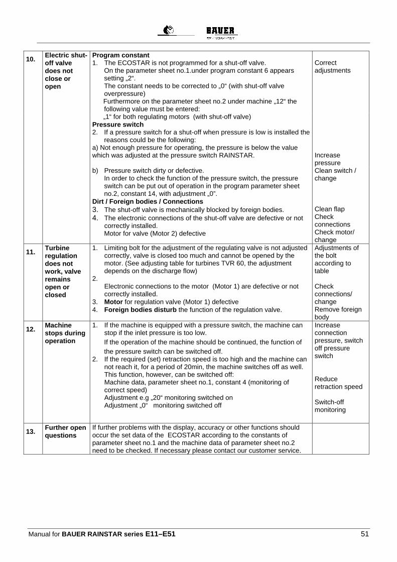
Manual for BAUER RAINSTAR series E11–E51 51
10. Electric shut-off valve does not close or open
Program constant 1. The ECOSTAR is not programmed for a shut-off valve.
On the parameter sheet no.1.under program constant 6 appears setting „2“. The constant needs to be corrected to „0“ (with shut-off valve overpressure)
Furthermore on the parameter sheet no.2 under machine „12“ the following value must be entered:
Correct adjustments
„1“ for both regulating motors (with shut-off valve)
Pressure switch 2. If a pressure switch for a shut-off when pressure is low is installed the
reasons could be the following: a) Not enough pressure for operating, the pressure is below the value which was adjusted at the pressure switch RAINSTAR.
Increase pressure
b) Pressure switch dirty or defective. In order to check the function of the pressure switch, the pressure switch can be put out of operation in the program parameter sheet no.2, constant 14, with adjustment „0”.
Dirt / Foreign bodies / Connections 3. The shut-off valve is mechanically blocked by foreign bodies. 4. The electronic connections of the shut-off valve are defective or not
correctly installed. Motor for valve (Motor 2) defective
Clean switch / change Clean flap Check connections Check motor/ change
11. Turbine regulation does not work, valve remains open or closed
1. Limiting bolt for the adjustment of the regulating valve is not adjusted correctly, valve is closed too much and cannot be opened by the motor. (See adjusting table for turbines TVR 60, the adjustment depends on the discharge flow)
2. Electronic connections to the motor (Motor 1) are defective or not correctly installed.
3. Motor for regulation valve (Motor 1) defective 4. Foreign bodies disturb the function of the regulation valve.
Adjustments of the bolt according to table Check connections/ change Remove foreign body
12. Machine stops during operation
1. If the machine is equipped with a pressure switch, the machine can stop if the inlet pressure is too low.
If the operation of the machine should be continued, the function of
the pressure switch can be switched off. 2. If the required (set) retraction speed is too high and the machine can
not reach it, for a period of 20min, the machine switches off as well. This function, however, can be switched off: Machine data, parameter sheet no.1, constant 4 (monitoring of correct speed) Adjustment e.g „20“ monitoring switched on Adjustment „0“ monitoring switched off
Increase connection pressure, switch off pressure switch Reduce retraction speed Switch-off monitoring
13. Further open questions
If further problems with the display, accuracy or other functions should occur the set data of the ECOSTAR according to the constants of parameter sheet no.1 and the machine data of parameter sheet no.2 need to be checked. If necessary please contact our customer service.

Manual for BAUER RAINSTAR Series E11–E51 52
8.1.2 TABLE FOR PRE-AND POST-IRRIGATION In order to correct irregularities at the beginning or at the end of the irrigation strip the ECOSTAR has the function pre- and post-irrigation. The precipitation height at the beginning of the strip (pre-irrigation) and at the end of the strip(post-irrigation) is reached by short interruptions of the cart retraction. The downtime for the pre-and post-irrigation is adjusted at the ECOSTAR with the program constant 2 and 3 on the parameter sheet no.1. The program constant 8 was pre-set in the factory. This factor links the retraction speed of the sprinkler with the pre- and post-irrigation time. The adjusted factor can be changed, whereby pre- and post-irrigation changes. The following table shows the pre-and post-irrigation times in minutes (rounded) at different adjustment factors:
Pro
gra
m
con
stan
t
Retraction speed in m/h Pre-and post-irrigation time in min.
10 m/h 20 m/h 30 m/h 40 m/h 50 m/h 60 m/h 70 m/h 80 m/h 90 m/h 100 m/h
1 6,0 3,0 2,0 1,5 1,2 1,0 0,9 0,8 0,7 0,6 2 12,0 6,0 4,0 3,0 2,4 2,0 1,7 1,5 1,3 1,2 3 18,0 9,0 6,0 4,5 3,6 3,0 2,6 2,3 2,0 1,8 4 24,0 12,0 8,0 6,0 4,8 4,0 3,4 3,0 2,7 2,4 5 30,0 15,0 10,0 7,5 6,0 5,0 4,3 3,8 3,3 3,0 6 36,0 18,0 12,0 9,0 7,2 6,0 5,1 4,5 4,0 3,6 7 42,0 21,0 14,0 10,5 8,4 7,0 6,0 5,3 4,7 4,2
8 48,0 24,0 16,0 12,0 9,6 8,0 6,9 6,0 5,3 4,8
9 54,0 27,0 18,0 13,5 10,8 9,0 7,7 6,8 6,0 5,4 10 60,0 30,0 20,0 15,0 12,0 10,0 8,6 7,5 6,7 6,0 11 66,0 33,0 22,0 16,5 13,2 11,0 9,4 8,3 7,3 6,6 12 72,0 36,0 24,0 18,0 14,4 12,0 10,3 9,0 8,0 7,2 13 78,0 39,0 26,0 19,5 15,6 13,0 11,1 9,8 8,7 7,8 14 84,0 42,0 28,0 21,0 16,8 14,0 12,0 10,5 9,3 8,4 15 90,0 45,0 30,0 22,5 18,0 15,0 12,9 11,3 10,0 9,0
9. EMERGENCY SHUT-OFF
If something unforseen happens, the pipe retraction can be interrupted with the emergency shut-off. Pull the gear shift lever with the open hand from the “PE-pipe retraction“ position to the shut-off position (Do not operate the lever with the closed hand or release it immediately !). The gearbox is disengaged. A spring snubs the lever up (shut-off position) and the band brake prevents fast reversing of the PE-pipe and the reel.

Manual for BAUER RAINSTAR Series E11-E51 53
Slacken the PE-pipe by pushing down the gear shift lever carefully.
10. WINDING MECHANISM
The winding mechanism operates synchronously with the winding or unwinding of the PE-pipe. Starting from the reel it is operated through a chain and the helically grooved spindle transporting the winding carriage of the PE-pipe. The winding mechanism ensures that the PE-pipe is properly guided winding for winding. When you put the machine into operation for the first time, pull off the full length of the PE-pipe to let it take a circular shape under pressure and eliminate ovality. This step is essential for trouble-free operation of the winding mechanism.
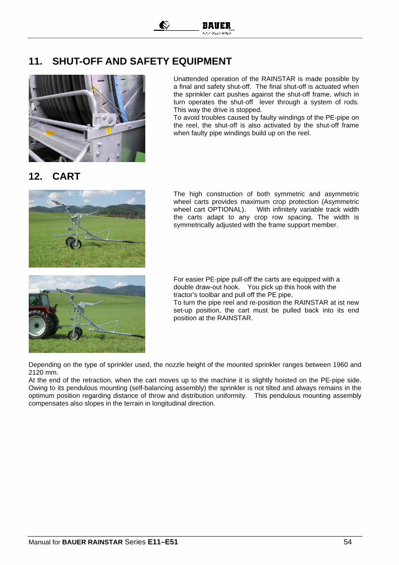
Manual for BAUER RAINSTAR Series E11–E51 54
11. SHUT-OFF AND SAFETY EQUIPMENT
Unattended operation of the RAINSTAR is made possible by a final and safety shut-off. The final shut-off is actuated when the sprinkler cart pushes against the shut-off frame, which in turn operates the shut-off lever through a system of rods. This way the drive is stopped. To avoid troubles caused by faulty windings of the PE-pipe on the reel, the shut-off is also activated by the shut-off frame when faulty pipe windings build up on the reel.
12. CART
The high construction of both symmetric and asymmetric wheel carts provides maximum crop protection (Asymmetric wheel cart OPTIONAL). With infinitely variable track width the carts adapt to any crop row spacing. The width is symmetrically adjusted with the frame support member.
For easier PE-pipe pull-off the carts are equipped with a double draw-out hook. You pick up this hook with the tractor’s toolbar and pull off the PE pipe. To turn the pipe reel and re-position the RAINSTAR at ist new set-up position, the cart must be pulled back into its end position at the RAINSTAR.
Depending on the type of sprinkler used, the nozzle height of the mounted sprinkler ranges between 1960 and 2120 mm. At the end of the retraction, when the cart moves up to the machine it is slightly hoisted on the PE-pipe side. Owing to its pendulous mounting (self-balancing assembly) the sprinkler is not tilted and always remains in the optimum position regarding distance of throw and distribution uniformity. This pendulous mounting assembly compensates also slopes in the terrain in longitudinal direction.
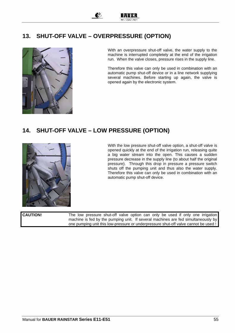
Manual for BAUER RAINSTAR Series E11-E51 55
13. SHUT-OFF VALVE – OVERPRESSURE (OPTION)
With an overpressure shut-off valve, the water supply to the
machine is interrupted completely at the end of the irrigation run. When the valve closes, pressure rises in the supply line. Therefore this valve can only be used in combination with an automatic pump shut-off device or in a line network supplying several machines. Before starting up again, the valve is opened again by the electronic system.
14. SHUT-OFF VALVE – LOW PRESSURE (OPTION)
With the low pressure shut-off valve option, a shut-off valve is
opened quickly at the end of the irrigation run, releasing quite a big water stream into the open. This causes a sudden pressure decrease in the supply line (to about half the original pressure). Through this drop in pressure a pressure switch shuts off the pumping unit and thus also the water supply. Therefore this valve can only be used in combination with an automatic pump shut-off device.
CAUTION!
The low pressure shut-off valve option can only be used if only one irrigation machine is fed by the pumping unit. If several machines are fed simultaneously by one pumping unit this low-pressure or underpressure shut-off valve cannot be used !
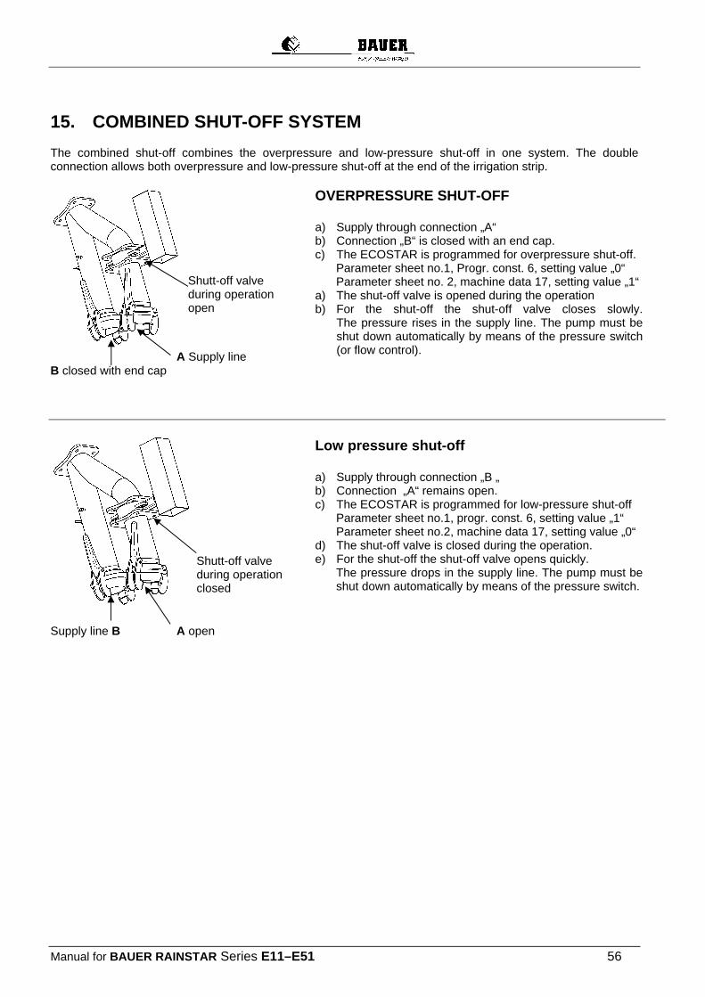
Manual for BAUER RAINSTAR Series E11–E51 56
15. COMBINED SHUT-OFF SYSTEM
The combined shut-off combines the overpressure and low-pressure shut-off in one system. The double connection allows both overpressure and low-pressure shut-off at the end of the irrigation strip.
A Supply line B closed with end cap
OVERPRESSURE SHUT-OFF a) Supply through connection „A“ b) Connection „B“ is closed with an end cap. c) The ECOSTAR is programmed for overpressure shut-off.
Parameter sheet no.1, Progr. const. 6, setting value „0“ Parameter sheet no. 2, machine data 17, setting value „1“
a) The shut-off valve is opened during the operation b) For the shut-off the shut-off valve closes slowly.
The pressure rises in the supply line. The pump must be shut down automatically by means of the pressure switch (or flow control).
Supply line B A open
Low pressure shut-off a) Supply through connection „B „ b) Connection „A“ remains open. c) The ECOSTAR is programmed for low-pressure shut-off
Parameter sheet no.1, progr. const. 6, setting value „1“ Parameter sheet no.2, machine data 17, setting value „0“
d) The shut-off valve is closed during the operation. e) For the shut-off the shut-off valve opens quickly.
The pressure drops in the supply line. The pump must be shut down automatically by means of the pressure switch.
Shutt-off valve during operation open
Shutt-off valve during operation closed
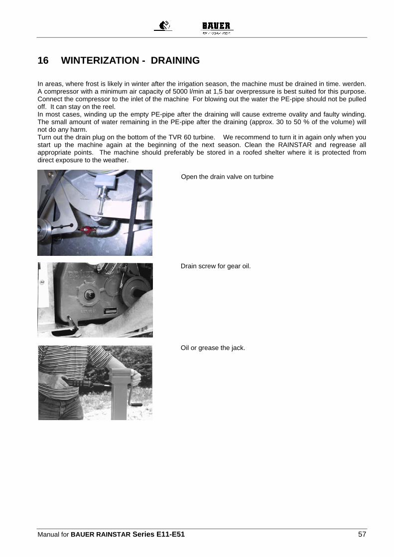
Manual for BAUER RAINSTAR Series E11-E51 57
16 WINTERIZATION - DRAINING
In areas, where frost is likely in winter after the irrigation season, the machine must be drained in time. werden. A compressor with a minimum air capacity of 5000 l/min at 1,5 bar overpressure is best suited for this purpose. Connect the compressor to the inlet of the machine For blowing out the water the PE-pipe should not be pulled off. It can stay on the reel. In most cases, winding up the empty PE-pipe after the draining will cause extreme ovality and faulty winding. The small amount of water remaining in the PE-pipe after the draining (approx. 30 to 50 % of the volume) will not do any harm. Turn out the drain plug on the bottom of the TVR 60 turbine. We recommend to turn it in again only when you start up the machine again at the beginning of the next season. Clean the RAINSTAR and regrease all appropriate points. The machine should preferably be stored in a roofed shelter where it is protected from direct exposure to the weather.
Drain screw for gear oil.
Oil or grease the jack.
Open the drain valve on turbine
Manual for BAUER RAINSTAR Series E11–E51 58
16.1 DRAINING THE PE-PIPE WITH THE BAUER BLOW-OUT AND COMPRESSOR UNIT Note the following instructions to ensure proper function of the blow-out unit: 1. The blow-out must be performed before further transport of the machine to ensure that no water is drained
from the PE pipe.
CAUTION!
If parts of the PE-pipe have run empty and air bubbles are enclosed in the pipe, the blow-out will not work !
2. If you use an electric shut-off valve, press the menu button „START“ so that the valve opens. 3. Connect a drain pipe at the inlet of the machine to avoid soaking the machine’s standing position.
CAUTION!
If you use the supply hose (7) for draining, make sure that the hose is not kinked and the water can run off freely.
PROCEDURE: The PE pipe is wound up on the reel, the cart is just before the shut-off position, take off the end cap (with bore and baffle plate) from the „garage“ (1). Press the plastic ball in the “garage“ down by hand or with a piece of wood until the ball gets to lie in the straight horizontal pipe (2) behind the outlet to the sprinkler. Close the shut-off vale (3) to the sprinkler..
Connect the pipe bend 90° (4) to the coupling „garage“ (1) and the compressor hose (5) to the pipe bend (4) and the compressor (6). The PE pipe can now be drained with the help of the compressor. Technical specifications of the compressor: Operating pressure: 1,5 bar sufficient Air capacity: minimum 5000 litres at 1,5 bar It does not take more than 5 to 8 minutes to drain the PE-pipe. If the blow-out takes longer, there are already air bubbles in the pipe that prevent further draining.

Manual for BAUER RAINSTAR Series E11-E51 59
After the blow-out and before opening the coupling, open the valve (3) so that the pressure in the PE pipe can escape !
Remove the fittings with the hose and couple the end cap with the baffle plate. The blow-out ball is in the inlet bend to the reel and the water will carry it back to the „garage“ (at the end of the horizontal pipe), when you resume irrigation.
ATTENTION!
Manual for BAUER RAINSTAR Series E11–E51 60
16.1.1 POSSIBLE FAULTS DURING PE-PIPE BLOW-OUT WITH COMPRESSOR
CAUTION! The end cap on the branch pipe of the horizontal pipe („“Garage“ of the plastic ball) must have a vent bore through which the branch pipe is deaerated when the ball is pressed to the cart by the water pressure from the turbine side. Then the plastic ball will park properly in the „“garage“ during irrigation. If this vent bore is missing, the plastic ball remains in the area of the horizontal pipe during irrigation and may cause considerable pressure loss on account of the reduced cross section..
Fault Remedy
PE-pipe has run empty. Put the irrigation machine under pressure again until a full jet without air bubbles is discharged at the sprinkler.
Kink in the drain hose from the turbine. Lay the hose straight without kinks or connect a rigid pipe.
Shut-off valves not opened. Open shut-off valves.
Plastic ball not in the correct position. Push down the plastic ball far enough to place it in the straight horizontal pipe
Incorrect plastic ball diameter. Required ball diameter:
PE-pipe dia. 100mm : Ball : 100mm
110mm : : 100mm
120mm : : 110mm
125mm : : 125mm
Plastic ball damaged. The ball must be round and faultless.
Insufficient compressor output. Check compressor performance data and safety valve

Manual for BAUER RAINSTAR Series E11-E51 61
16.1.2 SERVICE AND MAINTENANCE
We cannot emphasise often enough that proper service at the right time is essential for the operating reliability and service life of a machine. At the end of every irrigation season the RAINSTAR should be thoroughly checked and cleaned, and all parts greased carefully.
Machine part Service interval Lubricant, grease, oil
1. Helically grooved spindle of the winding mechanism
every 250 hours multi-purpose grease ( Alvania Grease )
2. Drive chain of winding mechanism
every 250 hours or as required
multi-purpose grease ( Alvania Grease )
3. Driver (spindle nut) of winding mechanism
every 250 hours, replacement recommended after 2500 service hours
multi-purpose grease ( Alvania Grease )
4. Driving chain every 250 hours or as required
multi-purpose grease ( Alvania Grease )
5. Turbine (see separate instruction)
every 250 hours multi-purpose grease ( Alvania Grease )
6. Change-speed gear
Change oil for first time after 500service hours and then every 500 to 800 hours or at least once a year
Gear lubricant oil CLP – DIN 51517 –
Teil 3, ISO VG 220 - 11,3 l
7. Ball race every 500 hours through grease nipple multi-purpose grease ( Alvania Grease )
8. Jack as required multi-purpose grease (Alvania Grease) through grease nipple
9. Machine supports (sliding parts)
as required multi-purpose grease ( Alvania Grease )
10. Screwed joints before putting into operation after 50 hours of operation
Tightening torques
Wheel nuts 300 Nm
Turntable side frame 210 Nm
Ball race on turntable and undercarriage E11 - E41 = 85 Nm
E 51 = 200 Nm
Drawbar on undercarriage 240 Nm
Hitch eye 200 Nm

Manual for BAUER RAINSTAR Series E11–E51 62
Lubricating the reel sealing When lubricating, the screw (1) is mounted to the lubricating tube (2). When lubrication is completed, the screw (1) is in ist place of deposit.
Screw in lubricating position Screw in lubricating position
2 1
1
New design 2007 Push the lever (3) to the insides during lubricating. Then pull out the lever (3) for irrigating.
Position for lubricating Position for irrigating Lubricant nipple 3
3
Manual for BAUER RAINSTAR Series E11–E51 63
17 FAULT FINDING
FAULT CAUSE REMEDY
The PE-pipe cannot be pulled off.
Incorrect gear shift lever position. Put it into the pull-off position.
Brake band sticks to the brake drum.
Loosen the brake band.
PE-pipe retraction stops before the final shut-off is actuated
Turbine blocked by a foreign body.
Remove the foreign body.
Pressure drop in supply line. Check pumping station and hydrant connections.
Overwinding of PE-pipe activates the safety shut-off.
Adjust the winding mechanism.
Repair broken winding chain.
The final shut-off is activated but the shut-off valve does not close.
Values for shut-off valve activation are not set correctly.
Adjust the settings according to the manual.
The reel overwinds or the windings become loose when the PE-pipe is pulled off.
Tractor stopped abruptly. Slow down gradually.
No oil in the change-speed gear. Refill oil.
The selected retraction speed is not reached
Incorrect drive transmission. Select proper gear transmission
Blocked sprinkler nozzle. Remove blockage.
General: Compare connecting pressure and water flow with performance chart values.
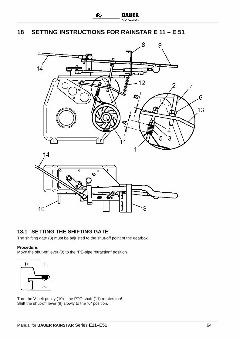
Manual for BAUER RAINSTAR Series E11–E51 64
18 SETTING INSTRUCTIONS FOR RAINSTAR E 11 – E 51
18.1 SETTING THE SHIFTING GATE The shifting gate (8) must be adjusted to the shut-off point of the gearbox. Procedure: Move the shut-off lever (9) to the “PE-pipe retraction“ position.
Turn the V-belt pulley (10) - the PTO shaft (11) rotates too!. Shift the shut-off lever (9) slowly to the “0“ position.

Manual for BAUER RAINSTAR Series E11–E51 65
The shut-off point is reached when the PTO shaft no longer rotates. Adjust the shifting gate (8) in this position according to the drawing (2 mm / 0,08 inch)! The spring (12) presses the shut-off lever (9) upward along the incline of the shifting gate and thus into the recess in the gearbox.
18.2 SETTING THE BAND BRAKE on the gear box The hex. nuts (2) of the band brake (1) with engaged transmission to B = 1 mm / 0,04 inch adjust. Lock the hex. nuts (2). Hex. nut (3) is tightened until the spring (5) is pre-tensioned at A = 22mm/0.86 inches , lock with nut (4).
18.3 SETTING THE THREADED ROD Shift the shut-off lever to the “PE -pipe pull-off” position.
Turn the hex. nuts (6) on the threaded rod (7) apart until the spacing between the brake lever (13) and the nut (4) is at C =2 mm/0.08 inch. Lock the hex. nut (6).shifting gate (8) and the shut-off lever (9) is about 4 to 5 mm. Secure the hex. nuts (6).
18.4 INSPECTING THE BAND BRAKE FOR RELEASE OF THE BRAKE BAND Move shut-off lever (9) to the “Release“ position. In this position the brake band must be slightly lifted off the brake disk. This prevents the brake band from sticking to the brake disk.

Manual for BAUER RAINSTAR Series E11–E51 66
CAUTION!
The brake band may stick after a longer standstill or after the winter period. It must be loosened before putting the machine into operation again !!! Do this by shortly turning the PTO shaft right and left with the hand wheel. If you do not observe this, the gearbox may break !!!
18.5 SETTING THE GEARBOX SHUT-OFF In the operating position the spacing between the shut-off frame (13) and the reel (17) is x = 25 mm/1 inch Set the shut-off frame (13) in the shut-off position at X mm from the reel (17) (see chart). Put the shut-off lever (9) into the shut-off position.
Adjust the hex. nut (15) on the control lever (16) to the bracket (14) of the shut-off frame.
Secure the nut
Pipe X 90 70mm / 2,8 inch
100 70mm / 2,8 inch 110 70mm / 2,8 inch 120 70mm / 2,8 inch 125 70mm / 2,8 inch

Manual for BAUER RAINSTAR Series E11–E51 67
18.6 TESTING THE SHUT-OFF:
Put the shut-off frame into operating position ( X = 25 mm / 1 inch ) Move the shut-off lever (9) to the „PE pipe retraction“ position. Pull the shut-off frame (13) to the shut-off position ( = X mm from reel ). The shut-off lever must jump into the shut-off position!
18.7 ADJUSTING THE WINDING MECHANISM
Step 1: Pull off the PE pipe and adjust the connecting bend (7) in a vertical position pointing down (except for E 51 PE-Pipe 120, inner width of reel 1600 mm, =80°). Step 2: Loosen the winding chain (1) between the reel and the helically grooved spindle (2). Step 3: Fasten the two guide bars (4 and 5) symmetrically at distance X 2 on the guide part (3). Mount the roller bracket (6) with the roller. Step 4: Move the guide part (3) of the winding carriage to the outermost reversing point of the groove on the right by turning the helically grooved spindle. Loosen both pillow blocks. ( Screws M12 ) Check the connection of pillow block – helically grooved spindle, if safety screws ( grub screw ) are tightened. The pillow block must rest on the shaft shoulder of the helically grooved spindle (2).
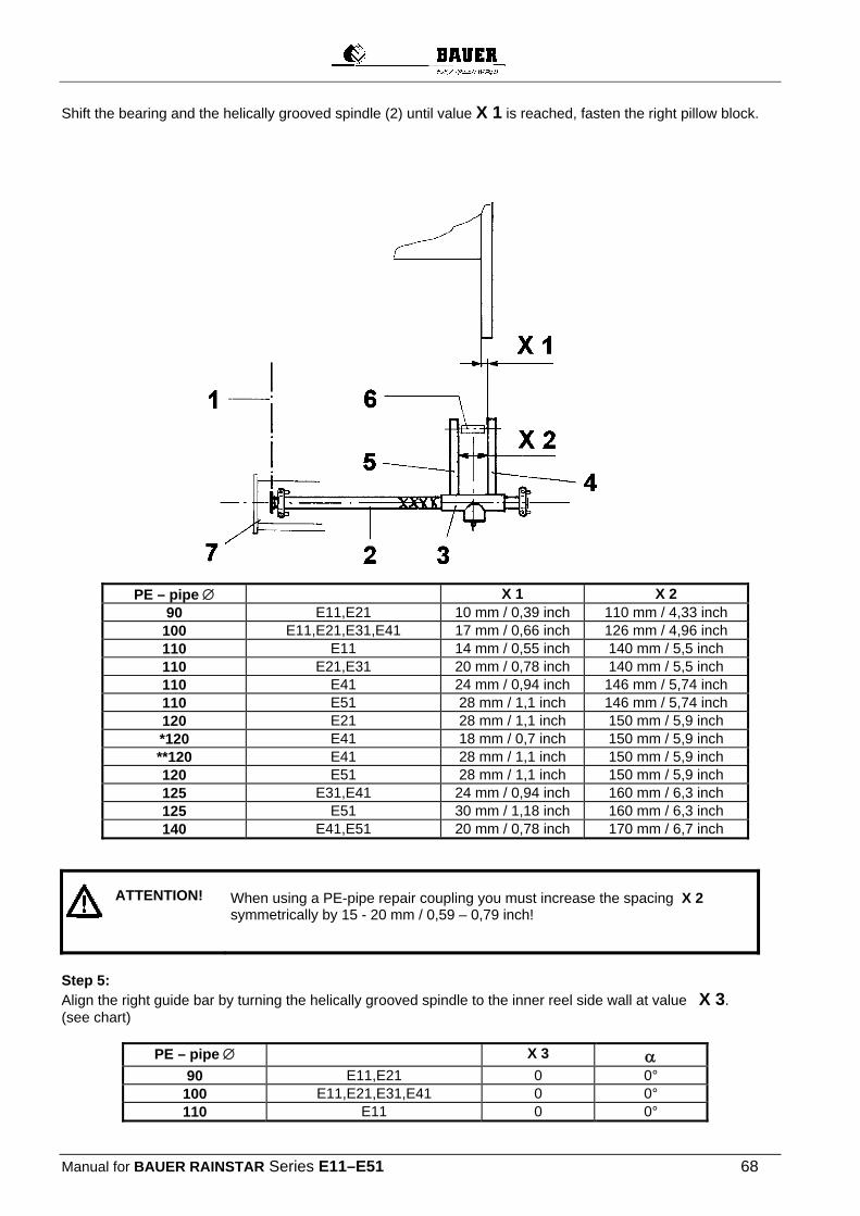
Manual for BAUER RAINSTAR Series E11–E51 68
Shift the bearing and the helically grooved spindle (2) until value X 1 is reached, fasten the right pillow block.
PE – pipe X 1 X 2 90 E11,E21 10 mm / 0,39 inch 110 mm / 4,33 inch
100 E11,E21,E31,E41 17 mm / 0,66 inch 126 mm / 4,96 inch 110 E11 14 mm / 0,55 inch 140 mm / 5,5 inch 110 E21,E31 20 mm / 0,78 inch 140 mm / 5,5 inch 110 E41 24 mm / 0,94 inch 146 mm / 5,74 inch 110 E51 28 mm / 1,1 inch 146 mm / 5,74 inch 120 E21 28 mm / 1,1 inch 150 mm / 5,9 inch *120 E41 18 mm / 0,7 inch 150 mm / 5,9 inch **120 E41 28 mm / 1,1 inch 150 mm / 5,9 inch 120 E51 28 mm / 1,1 inch 150 mm / 5,9 inch 125 E31,E41 24 mm / 0,94 inch 160 mm / 6,3 inch 125 E51 30 mm / 1,18 inch 160 mm / 6,3 inch 140 E41,E51 20 mm / 0,78 inch 170 mm / 6,7 inch
When using a PE-pipe repair coupling you must increase the spacing X 2 symmetrically by 15 - 20 mm / 0,59 – 0,79 inch!
Step 5: Align the right guide bar by turning the helically grooved spindle to the inner reel side wall at value X 3. (see chart)
PE – pipe X 3 90 E11,E21 0 0°
100 E11,E21,E31,E41 0 0° 110 E11 0 0°
ATTENTION!
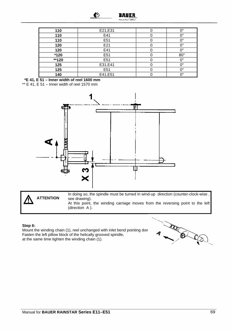
Manual for BAUER RAINSTAR Series E11–E51 69
110 E21,E31 0 0° 110 E41 0 0° 110 E51 0 0° 120 E21 0 0° 120 E41 0 0° *120 E51 0 80° **120 E51 0 0° 125 E31,E41 0 0° 125 E51 0 0° 140 E41,E51 0 0°
*E 41, E 51 – Inner width of reel 1600 mm ** E 41, E 51 – Inner width of reel 1570 mm
In doing so, the spindle must be turned in wind-up direction (counter-clock-wise ,
see drawing). At this point, the winding carriage moves from the reversing point to the left (direction A ).
Step 6: Mount the winding chain (1), reel unchanged with inlet bend pointing down. Fasten the left pillow block of the helically grooved spindle, at the same time tighten the winding chain (1).
ATTENTION
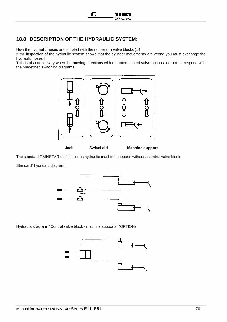
Manual for BAUER RAINSTAR Series E11–E51 70
18.8 DESCRIPTION OF THE HYDRAULIC SYSTEM: Now the hydraulic hoses are coupled with the non-return valve blocks (14). If the inspection of the hydraulic system shows that the cylinder movements are wrong you must exchange the hydraulic hoses ! This is also necessary when the moving directions with mounted control valve options do not correspond with the predefined switching diagrams.
Jack Swivel aid Machine support The standard RAINSTAR outfit includes hydraulic machine supports without a control valve block. Standard“ hydraulic diagram:
Hydraulic diagram “Control valve block - machine supports“ (OPTION)
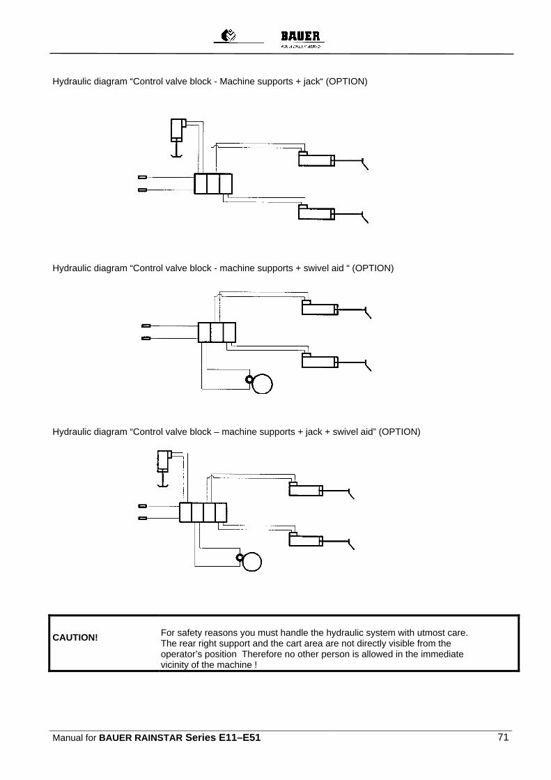
Manual for BAUER RAINSTAR Series E11–E51 71
Hydraulic diagram “Control valve block - Machine supports + jack“ (OPTION)
Hydraulic diagram “Control valve block - machine supports + swivel aid “ (OPTION)
Hydraulic diagram “Control valve block – machine supports + jack + swivel aid” (OPTION)
CAUTION!
For safety reasons you must handle the hydraulic system with utmost care. The rear right support and the cart area are not directly visible from the operator’s position Therefore no other person is allowed in the immediate vicinity of the machine !
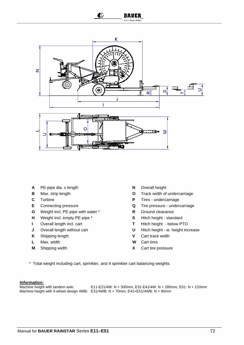
Manual for BAUER RAINSTAR Series E11–E51 72
A PE-pipe dia. x length
B Max. strip length
C Turbine
E Connecting pressure
G Weight incl. PE-pipe with water *
H Weight incl. empty PE-pipe *
I Overall length incl. cart
J Overall length without cart
K Shipping length
L Max. width
M Shipping width
N Overall height
O Track width of undercarriage
P Tires - undercarriage
Q Tire pressure - undercarriage
R Ground clearance
S Hitch height - standard
T Hitch height - below PTO
U Hitch height - w. height increase
V Cart track width
W Cart tires
X Cart tire pressure
* Total weight including cart, sprinkler, and 4 sprinkler cart balancing weights. Information:
Machine height with tandem axle: E11-E21/4W: N + 300mm, E31-E41/4W: N + 280mm, E51: N + 210mm Machine height with 4-wheel design 4WB: E31/4WB: N + 70mm, E41+E51/4WB: N + 90mm
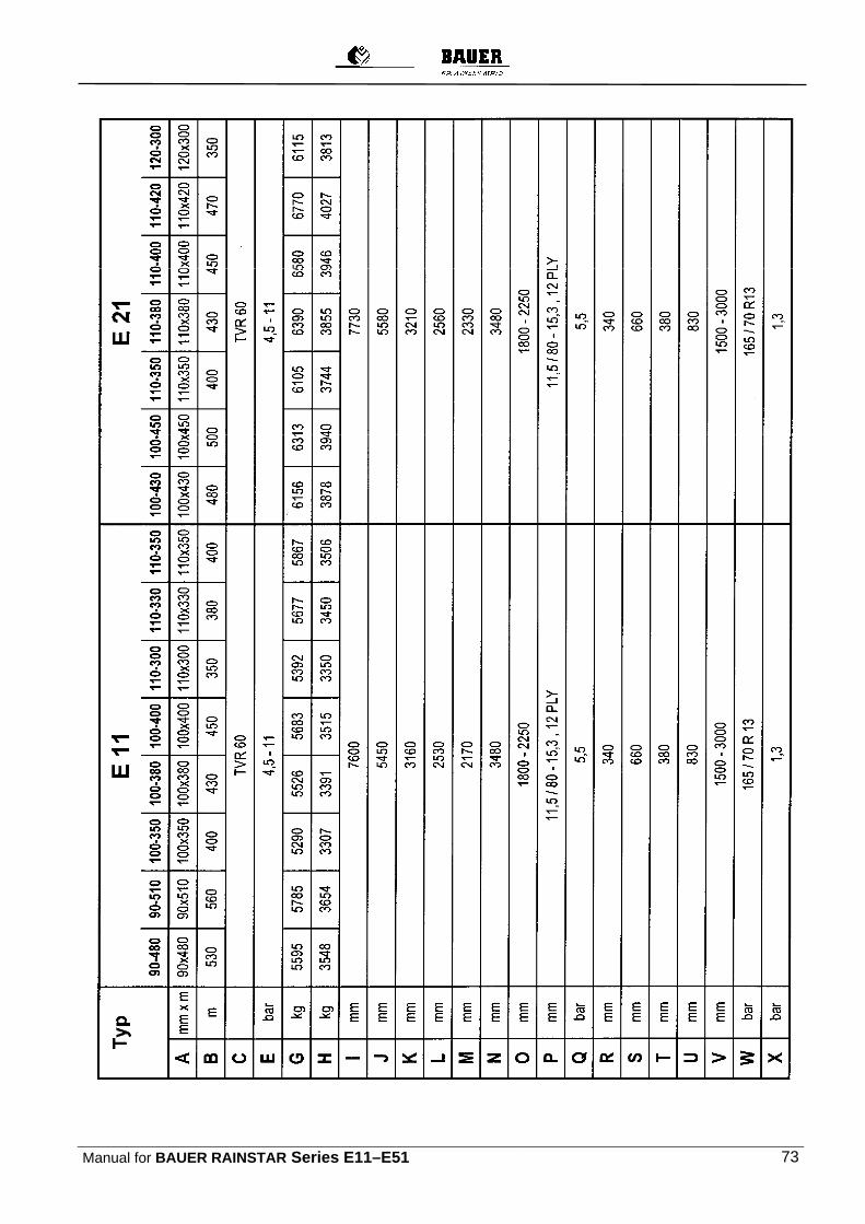
Manual for BAUER RAINSTAR Series E11–E51 73
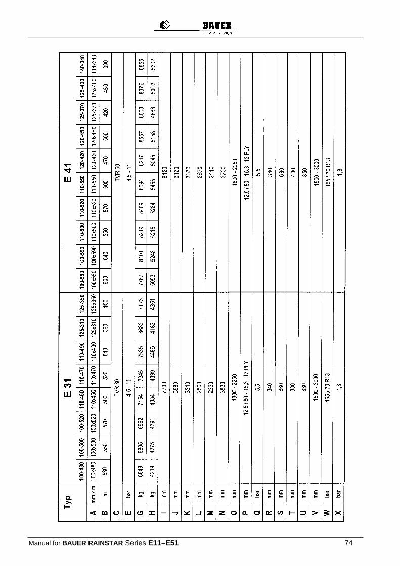
Manual for BAUER RAINSTAR Series E11–E51 74

Manual for BAUER RAINSTAR Series E11–E51 75
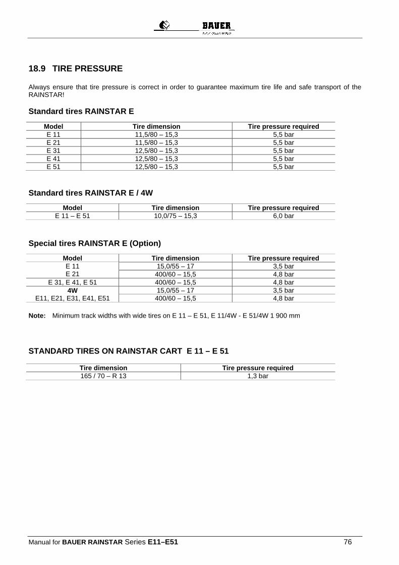
Manual for BAUER RAINSTAR Series E11–E51 76
18.9 TIRE PRESSURE Always ensure that tire pressure is correct in order to guarantee maximum tire life and safe transport of the RAINSTAR! Standard tires RAINSTAR E
Model Tire dimension Tire pressure required E 11 11,5/80 – 15,3 5,5 bar E 21 11,5/80 – 15,3 5,5 bar E 31 12,5/80 – 15,3 5,5 bar E 41 12,5/80 – 15,3 5,5 bar E 51 12,5/80 – 15,3 5,5 bar
Standard tires RAINSTAR E / 4W
Model Tire dimension Tire pressure required E 11 – E 51 10,0/75 – 15,3 6,0 bar
Special tires RAINSTAR E (Option)
Model Tire dimension Tire pressure required E 11 E 21
15,0/55 – 17 3,5 bar 400/60 – 15,5 4,8 bar
E 31, E 41, E 51 400/60 – 15,5 4,8 bar 4W
E11, E21, E31, E41, E51 15,0/55 – 17 3,5 bar 400/60 – 15,5 4,8 bar
Note: Minimum track widths with wide tires on E 11 – E 51, E 11/4W - E 51/4W 1 900 mm
STANDARD TIRES ON RAINSTAR CART E 11 – E 51
Tire dimension Tire pressure required 165 / 70 – R 13 1,3 bar
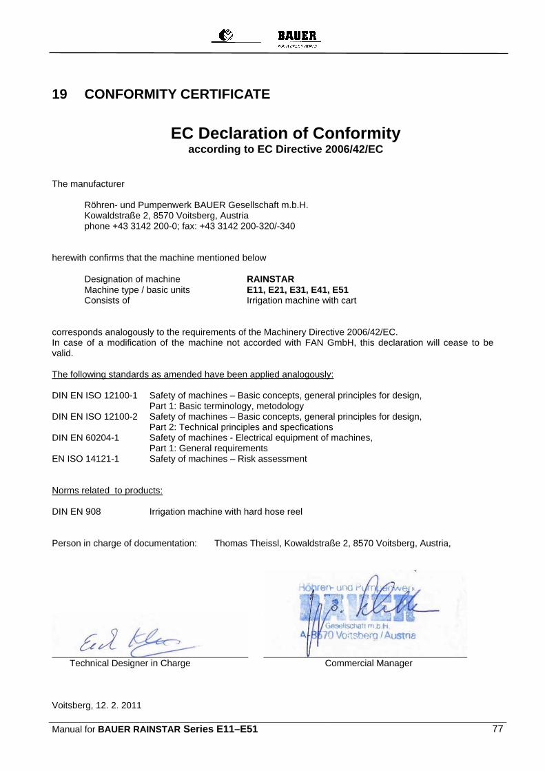
Manual for BAUER RAINSTAR Series E11–E51 77
19 CONFORMITY CERTIFICATE
EC Declaration of Conformity according to EC Directive 2006/42/EC
The manufacturer
Röhren- und Pumpenwerk BAUER Gesellschaft m.b.H. Kowaldstraße 2, 8570 Voitsberg, Austria phone +43 3142 200-0; fax: +43 3142 200-320/-340
herewith confirms that the machine mentioned below
Designation of machine RAINSTAR Machine type / basic units E11, E21, E31, E41, E51 Consists of Irrigation machine with cart
corresponds analogously to the requirements of the Machinery Directive 2006/42/EC. In case of a modification of the machine not accorded with FAN GmbH, this declaration will cease to be valid. The following standards as amended have been applied analogously: DIN EN ISO 12100-1 Safety of machines – Basic concepts, general principles for design, Part 1: Basic terminology, metodology DIN EN ISO 12100-2 Safety of machines – Basic concepts, general principles for design, Part 2: Technical principles and specfications DIN EN 60204-1 Safety of machines - Electrical equipment of machines, Part 1: General requirements EN ISO 14121-1 Safety of machines – Risk assessment Norms related to products: DIN EN 908 Irrigation machine with hard hose reel Person in charge of documentation: Thomas Theissl, Kowaldstraße 2, 8570 Voitsberg, Austria,
Technical Designer in Charge Commercial Manager Voitsberg, 12. 2. 2011