series 10- valve manifold common specifications sv manifolds.pdf · ex500-ac000-s attach a terminal...
TRANSCRIPT

Air c
ylin
der
Rota
ry a
ctu
ato
rA
ir g
ripper
Directional contr
ol
valv
eF
ittings &
Tubin
gP
ressure
sw
itch
Cle
an g
as filt
er
Flo
w c
ontr
ol
equip
ment
Filt
er,
Pre
ssure
contr
ol equip
ment
Air p
repara
tion
equip
ment
· Changing the number of stations
can be easily done by lever operation.
· 34 pins connector allows up to
16 stations with double solenoids.
Tie-rod base manifold
Cassette base manifold Applicable series
Manifold type
1 (P: SUP) / 3, 5 (E: EXH) type
Valve stations (maximum)
Max. number of solenoids
Port size
10-SV1000
18 stations
18 points
C8, N9
C3, C4, C6
N1, N3, N7
10-SV2000
20 stations
26 points
C10, N11
C4, C6, C8
N3, N7, N9
Stacking type cassette base manifold
Common SUP, EXH
1(P), 3/5(E) port
4(A), 2(B) port
Manifold specifications
Applicable series
Manifold type
1 (P: SUP) / 3, 5 (E: EXH) type
Valve stations (maximum)
Max. number of solenoids
Port size
10-SV1000
C8, N9
C3, C4, C6
N1, N3, N7
10-SV2000
C10, N11
C4, C6, C8
N3, N7, N9
10-SV3000
C12, N11
C6, C8, C10
N7, N9, N11
10-SV4000
C12, N11,03
C8, C10, C12
N9, N11, 02, 03
Tie-rod base manifold
Common SUP, EXH
20 stations
32 points
1(P), 3/5(E) port
4(A), 2(B) port
Manifold specifications
Series
Series EX500 Decentralized serial wiring
Series EX250 Serial wiring with input/output unit
Series EX120 Dedicated output serial wiring
For circular connector
D-sub connector
Flat ribbon cable
∗ Enclosure of a gateway unit and input manifold is IP65.
Enclosure (Based on IEC529)
IP67 ∗
IP67
Dusttight (IP40)
IP67
Dusttight (IP40)
Dusttight (IP40)
Enclosure of manifold variations (Common for cassette base and tie-rod base)
Model
10-SS5V1-16
10-SS5V2-16
1,5,3
(P,EA,EB)
C8
C10
4,2
(A,B)
C6
C8
Port size Flow characteristics
1→4/2(P→A/B) 4/2→3/5(A/B→E)
Note) The value is for manifold base with 5 stations and individually operated 2 position type.
Flow characteristics
C[dm3/(s·bar)]
0.89
2.3
b
0.22
0.28
Cv
0.22
0.50
C[dm3/(s·bar)]
0.98
2.7
b
0.21
0.18
Cv
0.23
0.56
Note) The value is for manifold base with 5 stations and individually operated 2 position type.
Model
10-SS5V1-10
10-SS5V2-10
10-SS5V3-10
10-SS5V4-10
1,5,3
(P,EA,EB)
C8
C10
C12
C12
4,2
(A,B)
C6
C8
C10
C12
Port size Flow characteristics
1→4/2(P→A/B) 4/2→3/5(A/B→E)
Flow characteristics
C[dm3/(s·bar)]
0.98
2.1
4.2
6.2
b
0.26
0.20
0.22
0.19
Cv
0.24
0.46
0.91
1.3
C[dm3/(s·bar)]
1.1
2.4
4.3
7.0
b
0.35
0.18
0.21
0.18
Cv
0.28
0.48
0.93
1.6
Series 10-SV Valve manifold common specifications
239
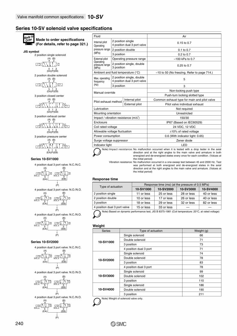
Valve manifold common specifications 10-SV
Fluid
Ambient and fluid temperature (°C)
Manual override
Pilot exhaust method
Lubrication
Mounting orientation
Impact / vibration resistance (m/s2)
Enclosure
Coil rated voltage
Allowable voltage fluctuation
Power consumption
Surge voltage suppressor
Indicator light
Air
0.15 to 0.7
0.1 to 0.7
0.2 to 0.7
–100 kPa to 0.7
0.25 to 0.7
–10 to 50 (No freezing. Refer to page 714.)
5
3
Non-locking push type
Push-turn locking slotted type
Common exhaust type for main and pilot valve
Pilot valve individual exhaust
Not required
Unrestricted
150/30
IP67 (Based on IEC60529)
24 VDC, 12 VDC
±10% of rated voltage
0.6 (With indicator light: 0.65)
Zener diode
LED
2 position single
4 position dual 3 port valve
2 position double
3 position
Operating pressure range
2 position single, double3 position
2 position single, double4 position dual 3 port valve
3 position
Internal pilot
Operating
pressure range
(MPa)
External pilotOperating pressure range(MPa)
Max. operating frequency(Hz)
Internal pilot
External pilot
Note) Based on dynamic performance test, JIS B 8375-1981 (Coil temperature: 20°C, at rated voltage)
Type of actuation
2 position single
2 position double
3 position
4 position dual 3 port valve
10-SV1000
11 or less
10 or less
18 or less
15 or less
10-SV2000
25 or less
17 or less
29 or less
33 or less
10-SV3000
28 or less
26 or less
32 or less
—
10-SV4000
40 or less
40 or less
82 or less
—
Response time
Response time (ms) (at the pressure of 0.5 MPa)
Series Type of actuation
Single solenoid
Double solenoid
3 position
4 position dual 3 port
Single solenoid
Double solenoid
3 position
4 position dual 3 port
Single solenoid
Double solenoid
3 position
Single solenoid
Double solenoid
3 position
10-SV1000
10-SV2000
10-SV3000
10-SV4000
Weight (g)
66
71
73
71
74
78
83
78
99
102
110
186
190
211
Weight
Note) Weight of solenoid valve only.
Series 10-SV solenoid valve specifications
JIS symbol2 position single solenoid
2 position double solenoid
3 position closed center
3 position exhaust center
3 position pressure center
4 position dual 3 port valve: N.C./N.C.
4 position dual 3 port valve: N.O./N.O.
4 position dual 3 port valve: N.C./N.O.
(A)4
(B)2
5(EA)
1(P)
3(EB)
(A)4
(B)2
5(EA)
1(P)
3(EB)
(A)4
(B)2
5(EA)
1(P)
3(EB)
(A)4
(B)2
5(EA)
1(P)
3(EB)
(A)4
(A)4
(A)4
(A)4
(B)2
(B)2
(B)2
(B)2
5(EA)
1(P)
3(EB)
5(EA)
5(EA)
5(EA)
1(P)
1(P)
1(P)
SOL.bSOL.a3
(EB)
3(EB)
3(EB)
SOL.bSOL.a
SOL.bSOL.a
Series 10-SV1000
4 position dual 3 port valve: N.C./N.C.
4 position dual 3 port valve: N.O./N.O.
4 position dual 3 port valve: N.C./N.O.
(A)4
(A)4
(A)4
(B)2
(B)2
(B)2
5(EA)
5(EA)
5(EA)
1(P)
1(P)
1(P)
SOL.bSOL.a3
(EB)
3(EB)
3(EB)
SOL.bSOL.a
SOL.bSOL.a
Series 10-SV2000
Made to order specifications
(For details, refer to page 321.)
240
Note) Impact resistance:
Vibration resistance:
No malfunction occurred when it is tested with a drop tester in the axial
direction and at the right angles to the main valve and armature in both
energized and de-energized states every once for each condition. (Values at
the initial period)
No malfunction occurred in a one-sweep test between 45 and 2000 Hz. Test
was performed at both energized and de-energized states in the axial
direction and at the right angles to the main valve and armature. (Values at
the initial period)
Made to
Order

Air c
ylin
der
Rota
ry a
ctu
ato
rA
ir g
ripper
Directional contr
ol
valv
eF
ittings &
Tubin
gP
ressure
sw
itch
Cle
an g
as filt
er
Flo
w c
ontr
ol
equip
ment
Filt
er,
Pre
ssure
contr
ol equip
ment
Air p
repara
tion
equip
ment
241
Decentralized serial wiring
Series EX500 IP67 compliant
Tie-rod base
Cassette base
Applicable
series
Cassette base manifold
10-SV1000/10-SV2000
Tie-rod base manifold
10-SV1000/10-SV2000/10-SV3000/10-SV4000
· Number of output points: 16 points
· EX500 gateway unit communication specifications
Remote I/O, DeviceNet, PROFIBUS-DP, CC-Link
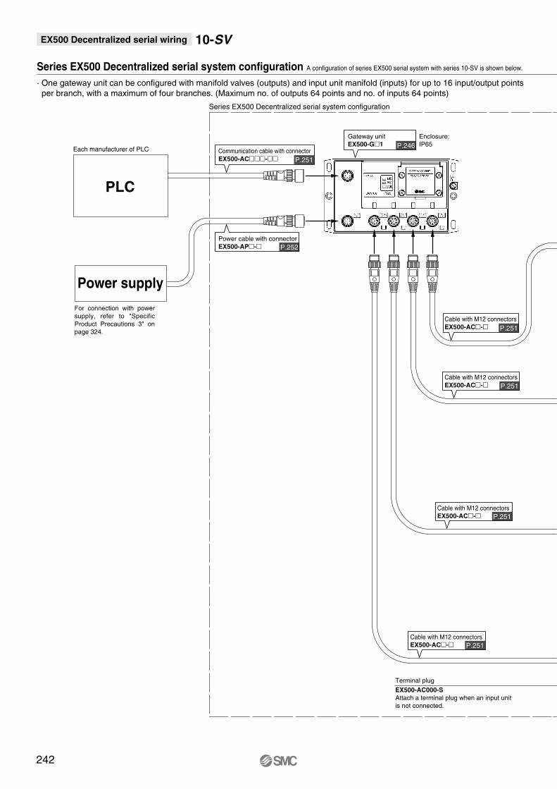
242
EX500 Decentralized serial wiring 10-SV
Series EX500 Decentralized serial system configuration A configuration of series EX500 serial system with series 10-SV is shown below.
P.252
P.251
P.246
P.251
P.251
P.251
P.251
· One gateway unit can be configured with manifold valves (outputs) and input unit manifold (inputs) for up to 16 input/output points
per branch, with a maximum of four branches. (Maximum no. of outputs 64 points and no. of inputs 64 points)
Cable with M12 connectors
EX500-AC-
Cable with M12 connectors
EX500-AC-
Power cable with connector
EX500-AP-
Communication cable with connector
EX500-AC-
Gateway unit
EX500-G1
Terminal plug
EX500-AC000-S
Attach a terminal plug when an input unit
is not connected.
Each manufacturer of PLC
Series EX500 Decentralized serial system configuration
Cable with M12 connectors
EX500-AC-
Cable with M12 connectors
EX500-AC-
Enclosure:
IP65
PLC
Power supply
For connection with power
supply, refer to "Specific
Product Precautions 3" on
page 324.

Air c
ylin
der
Rota
ry a
ctu
ato
rA
ir g
ripper
Directional contr
ol
valv
eF
ittings &
Tubin
gP
ressure
sw
itch
Cle
an g
as filt
er
Flo
w c
ontr
ol
equip
ment
Filt
er,
Pre
ssure
contr
ol equip
ment
Air p
repara
tion
equip
ment
EX500 Decentralized serial wiring 10-SV
243
P.244
P.248
P.251
P.251
P.251
Waterproof cap
EX500-AW
Included when shipped.
Connection of sensors with
M8, M12 connectors
(auto switch, pressure switch, etc.)
Connection of sensors with
M8, M12 connectors
(auto switch, pressure switch, etc.)
Connection of sensors with
M8, M12 connectors
(auto switch, pressure switch, etc.)
Connection to a large solenoid valve, etc.
· A separate power supply is required.
· No. of output point is ready for 1 point or 2 points.
· For details, refer to page 309.
Relay output module
Cable with M12 connectors
EX500-AC-
Series 10-SV manifold
10-SS5V-W10/16SAWDInput manifold
EEX500-IB1-
SV1000-60-5-1A
(Refer to page 309.)
Cable with M12 connectors
EX500-AC-
Cable with M12 connectors
EX500-AC-
Enclosure:
IP67Enclosure:
IP65

· Tie-rod base
· Cassette base
Series
--
-
1 A1W
Enclosure
IP67 specifications
1
2
10-SV1000
10-SV2000
- - - -D 0516S1 A1W
SI unit
Valve stations
For Remote I/OA1W
A2W
0
DIN rail length specified
Standard lengthNil
3
16
Note
Double wiring specifications
Specified layout Note 2)
(up to 16 solenoids possible)
Stations
2 stations
8 stations
2 stations
16 stations
Series
1
2
3
4
10-SV1000
10-SV2000
10-SV3000
10-SV4000
P, E port location
U
D
B
U side (2 to 10 stations)
D side (2 to 10 stations)
Both sides (2 to 16 stations)
Symbol
02
08
02
16
···
···
···
···
For 3 stations
For 16 stations
···
···
MountingDirect mounting
DIN rail mounting (with DIN rail)
DIN rail mounting (without DIN rail)
Nil
D
D0Note)
D3
D16
For 3 stations
For 16 stations
···
···
A, B port size (inch)
A, B portSymbol
N1
N3
N7
N3
N7
N9
N7
N9
N11
N9
N11
02N
03N
02T
03T
M
One-touch fitting for ø1/8"
One-touch fitting for ø5/32"
One-touch fitting for ø1/4"
One-touch fitting for ø5/32"
One-touch fitting for ø1/4"
One-touch fitting for ø5/16"
One-touch fitting for ø1/4"
One-touch fitting for ø5/16"
One-touch fitting for ø3/8"
One-touch fitting for ø5/16"
One-touch fitting for ø3/8"
NPT 1/4
NPT 3/8
NPTF 1/4
NPTF 3/8
A, B ports mixed
SUP/EXH block assembly specifications
Internal pilot
External pilot
Nil
R
Note 1)
∗ In the case of mixed specifications (M), indicate separately on the manifold specification sheet.∗ Port sizes of X, PE port for external pilot specification (R) are ø4 (metric), ø5/32" (inch) for 10-SV1000/2000 and ø6 (metric) and ø1/4" (inch) for 10-SV3000/4000.
- - -D 05 U10S
U
One-touch
fitting for ø5/16"
P, E port Applicable series
10-SV1000
10-SV2000
10-SV3000
10-SV4000
One-touch
fitting for ø3/8"
One-touch
fitting for ø3/8"
One-touch
fitting for ø3/8"
NPT3/8
NPTF3/8
A, B port size (metric)
A, B portSymbol
C3
C4
C6
C4
C6
C8
C6
C8
C10
C8
C10
C12
02
03
02F
03F
M
One-touch fitting for ø3.2
One-touch fitting for ø4
One-touch fitting for ø6
One-touch fitting for ø4
One-touch fitting for ø6
One-touch fitting for ø8
One-touch fitting for ø6
One-touch fitting for ø8
One-touch fitting for ø10
One-touch fitting for ø8
One-touch fitting for ø10
One-touch fitting for ø12
Rc 1/4
Rc 3/8
G 1/4
G 3/8
A, B ports mixed
One-touch
fitting for ø8
P, E port Applicable series
10-SV1000
10-SV2000
10-SV3000
10-SV4000
One-touch
fitting for ø10
One-touch
fitting for ø12
One-touch
fitting for ø12
Rc3/8
G3/8
SS5V10
SS5V10Clean series
Series 10-SV EX500 Decentralized serial wiring
How to Order
W
W
Without SI unit
For DeviceNet/For ProfiBus-DPCC-Link
244
When a longer DIN rail is desired than the specified stations.(Specify a longer rail than the standard length.)
Note) In the case of D0, only DIN rail fittings are attached.
Specify a longer rail than the standard length.
Double wiring specifications: Single, double, 3 position and 4 position solenoid valves can be used on all manifold stations.Use of a single solenoid will result in an unused control signal. If this is not desired, order with a specified layout.Specified layout: Indicate wiring specifications on the manifold specification sheet. (Note that double, 3 position and 4 position valves cannot be used where single solenoid wiring has been specified.)
Note 1)
Note 2)
Air c
ylin
der
Rota
ry a
ctu
ato
rA
ir g
ripper
Directional contr
ol
valv
eF
ittings &
Tubin
gP
ressure
sw
itch
Cle
an g
as filt
er
Flo
w c
ontr
ol
equip
ment
Filt
er,
Pre
ssure
contr
ol equip
ment
Air p
repara
tion
equip
ment
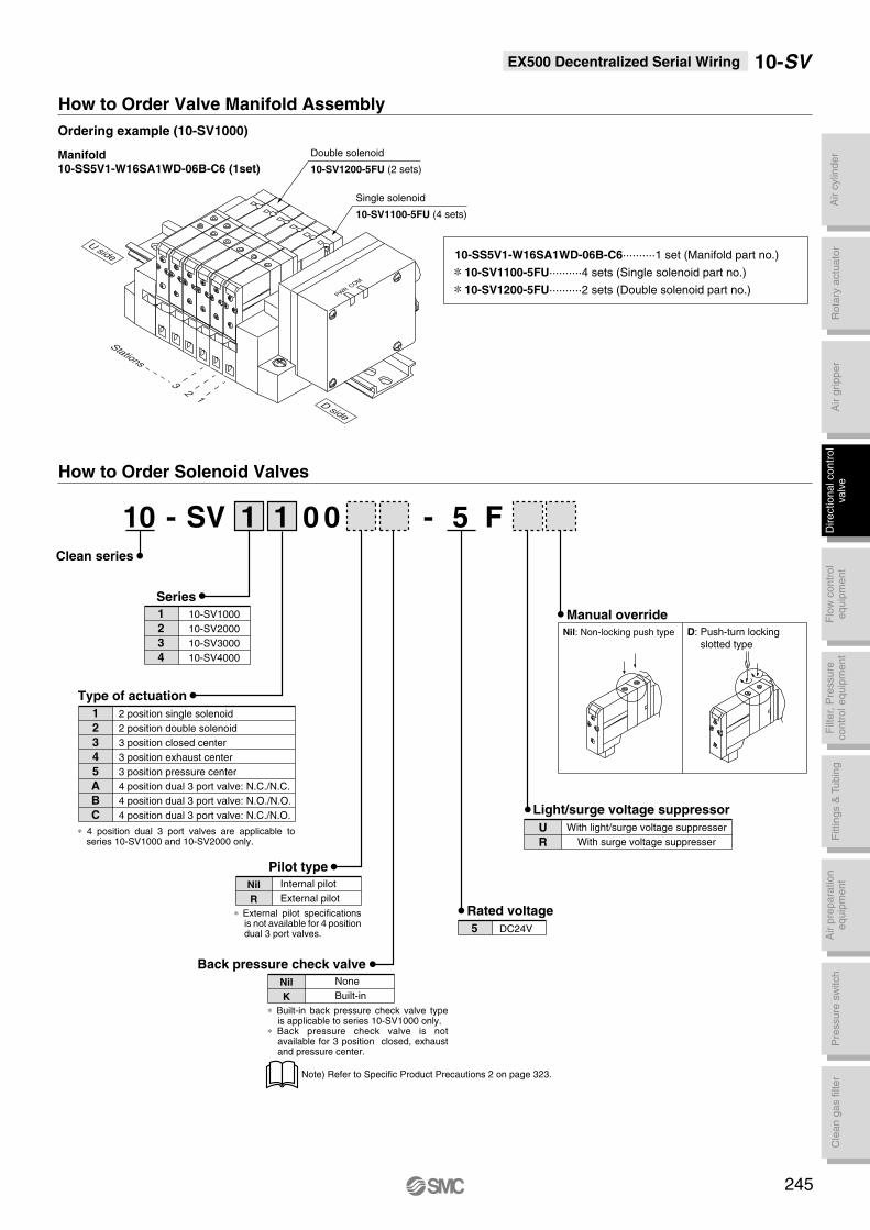
EX500 Decentralized Serial Wiring 10-SV
Ordering example (10-SV1000)
Manifold10-SS5V1-W16SA1WD-06B-C6 (1set)
10-SS5V1-W16SA1WD-06B-C6··········1 set (Manifold part no.)
10-SV1100-5FU··········4 sets (Single solenoid part no.)
10-SV1200-5FU··········2 sets (Double solenoid part no.)
Manual override
Rated voltage
Nil: Non-locking push type D: Push-turn locking
slotted type
-- 1 1 0 0 F5
5 DC24V
Light/surge voltage suppressor
With light/surge voltage suppresser
With surge voltage suppresser
U
R
Pilot type
∗ External pilot specifications is not available for 4 position dual 3 port valves.
∗ 4 position dual 3 port valves are applicable to series 10-SV1000 and 10-SV2000 only.
∗ Built-in back pressure check valve type is applicable to series 10-SV1000 only.
∗ Back pressure check valve is not available for 3 position closed, exhaust and pressure center.
Internal pilot
External pilot
Nil
R
Back pressure check valve
None
Built-in
Nil
K
Series
Clean series
1
2
3
4
10-SV1000
10-SV2000
10-SV3000
10-SV4000
Type of actuation
1
2
3
4
5
A
B
C
2 position single solenoid
2 position double solenoid
3 position closed center
3 position exhaust center
3 position pressure center
4 position dual 3 port valve: N.C./N.C.
4 position dual 3 port valve: N.O./N.O.
4 position dual 3 port valve: N.C./N.O.
Double solenoid
10-SV1200-5FU (2 sets)
Single solenoid
10-SV1100-5FU (4 sets)
32
1
Stations
U side
D side
PWR
COM
DD
DD
DD
Note) Refer to Specific Product Precautions 2 on page 323.
SV10
How to Order Valve Manifold Assembly
How to Order Solenoid Valves
245

EX500 Decentralized Serial Wiring 10-SV
How to Order
Specifications
Input unit manifold
Model EX500-GAB1-X1
Rockwell Automation,
Inc. PLC
57.6/115.2/
230.4 kbit/sec
DeviceNet
Release2.0
125/250/500
kbit/sec
PROFIBUS-DP
(EN50170)
9.6/19.2/45.45/93.75/187.5/500 kbit/sec1.5/3/6/12 Mbit/sec
CC-Link
Ver.1.10
156/625 kbit/sec
2.5/5/10 Mbit/sec
EX500-GDN1
—
—
Power for DeviceNet
11 to 25 VDC
Power for DeviceNet
50 mA or less
—
—
—
—
Input and control unit power supply: 24 VDC±10%
Solenoid valve power supply: 24 VDC+10%/–5%
(Power drop warning at approx. 20 V)
24 VDC
200 mA or less (GW unit)
Maximum 64 inputs / 16 outputs
4 branches (16 inputs / 16 outputs per branch)
8 core heavy duty cable
5 m or less (total extension 10 m or less)
M12 connector (8 pins, socket)
M12 connector (5 pins, plug)
+5 to +45°C/35 to 85% RH (No condensation)
IP65
UL, CSA, CE
470
EX500-GPR1A EX500-GMJ1
Rated voltage
Power supply voltage range
Current consumption
No. of input/output points
No. of input/output branches
Branch cable
Branch cable length
Communication connector
Power connector
Ambient operating temperature / humidity
Enclosure
Applicable standard
Weight (g)
Communication speed
Applicable PLC /
Communication protocol
Communication protocol
DN1
PR1A
AB1-X1
MJ1
DeviceNet
PROFIBUS-DP
Remote I/O (RIO)
CC-Link
EX500 G DN1Gateway (GW) unit
246
Air c
ylin
der
Rota
ry a
ctu
ato
rA
ir g
ripper
Directional contr
ol
valv
eF
ittings &
Tubin
gP
ressure
sw
itch
Cle
an g
as filt
er
Flo
w c
ontr
ol
equip
ment
Filt
er,
Pre
ssure
contr
ol equip
ment
Air p
repara
tion
equip
ment
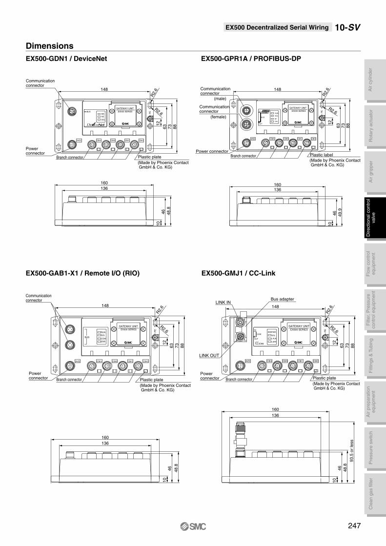
Dimensions
EX500-GDN1 / DeviceNet EX500-GPR1A / PROFIBUS-DP
EX500 SERIES
GATEWAY UNIT
24VDC COM A COM B COM C COM D
PEBUS
MS
NS
SOL
10
46
48.8
136
160
12
63
73
88
148
R2.
6
R2.6
OUT
IN
DIA
BF
SOL
RUN
BUS
EX500 SERIES
GATEWAY UNIT
24VDC COM A COM B COM C COM D
PE
10
136160
148
12
R2.
6
R2.6
(male)
(female)
EX500-GAB1-X1 / Remote I/O (RIO) EX500-GMJ1 / CC-Link
(Made by Phoenix Contact GmbH & Co. KG)
Plastic plate(Made by Phoenix Contact GmbH & Co. KG)
Plastic plate
(Made by Phoenix Contact GmbH & Co. KG)
Plastic plate
Branch connector
Branch connector
Powerconnector
Communicationconnector
Powerconnector
Communicationconnector
Communicationconnector
Communication connector
12
148
R2.6
R2.
6
EX500 SERIES
GATEWAY UNIT
ERR
COM
SOL
RUN
BUS
PE
COM DCOM CCOM BCOM A24VDC
160
136
46
10
48.8
Bus adapter
L ERR.
L RUN
SOL
PWRLINK
OUT
IN EX500 SERIES
GATEWAY UNIT
COM DCOM CCOM BCOM A24VDC
Powerconnector
LINK OUT
LINK IN
Branch connector
Power connectorBranch connector
(Made by Phoenix Contact GmbH & Co. KG)
Plastic label
93.5
or
less
148
160
136
48.8
46
10
88
73
631
2
R2.6R
2.6
PE
EX500 Decentralized Serial Wiring 10-SV
63
73
88
49.9
46
63
73
88
247
EX500 Decentralized Serial Wiring 10-SV
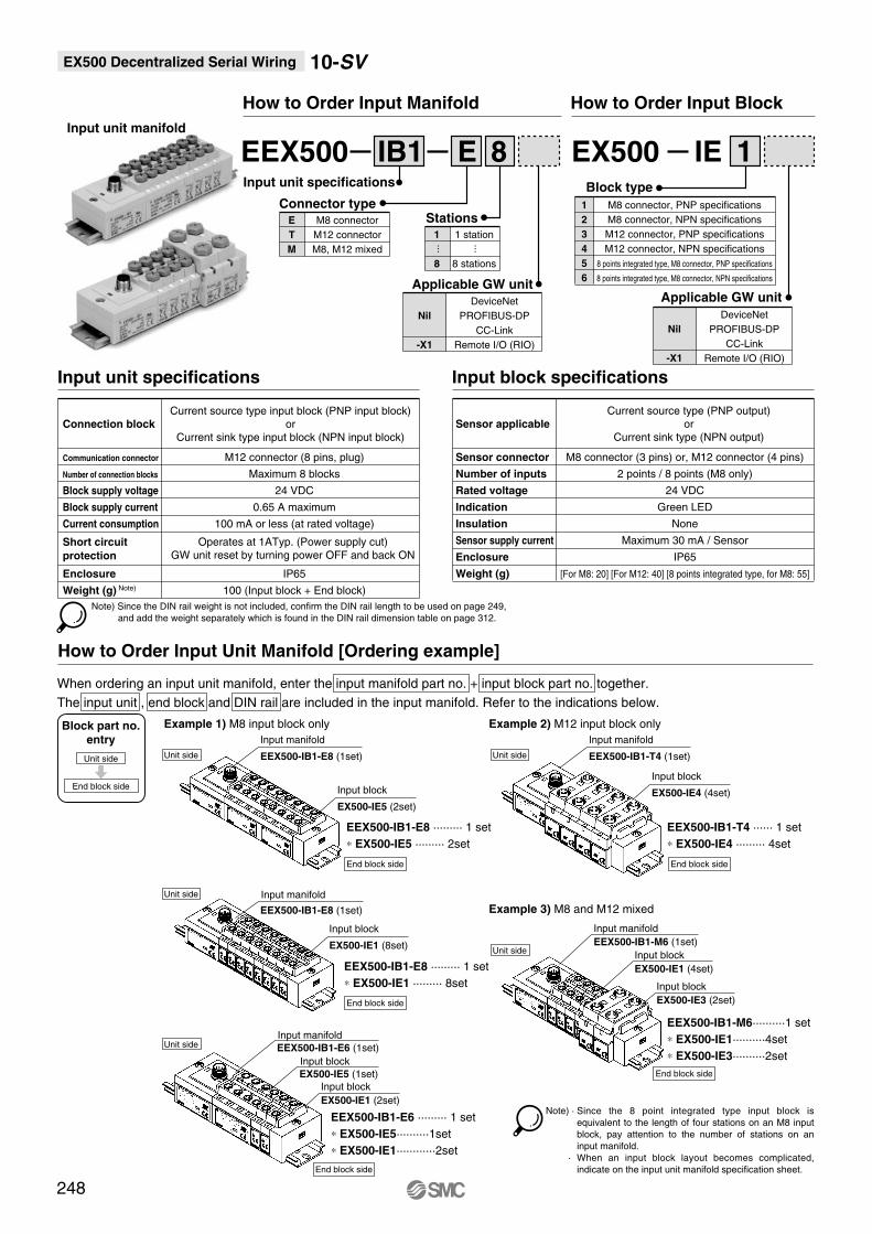
How to Order Input Block
Input unit manifold
EX500 IE
Nil
-X1
Applicable GW unit
DeviceNet
PROFIBUS-DP
CC-Link
Remote I/O (RIO)
1
1
2
3
4
5
6
Block type
M8 connector, PNP specifications
M8 connector, NPN specifications
M12 connector, PNP specifications
M12 connector, NPN specifications
8 points integrated type, M8 connector, PNP specifications
8 points integrated type, M8 connector, NPN specifications
How to Order Input Manifold
EEX500 IB1
1
8
Stations1 station
8 stations
Nil
-X1
Applicable GW unit
DeviceNet
PROFIBUS-DP
CC-Link
Remote I/O (RIO)
E 8
···
···
E
T
M
Connector typeM8 connector
M12 connector
M8, M12 mixed
Input unit specifications
Input unit specifications
Connection block
Communication connector
Number of connection blocks
Block supply voltage
Block supply current
Current consumption
Short circuit
protection
Enclosure
Weight (g) Note)
Current source type input block (PNP input block)
or
Current sink type input block (NPN input block)
Operates at 1ATyp. (Power supply cut)
GW unit reset by turning power OFF and back ON
M12 connector (8 pins, plug)
Maximum 8 blocks
24 VDC
0.65 A maximum
100 mA or less (at rated voltage)
IP65
100 (Input block + End block)
Input block specifications
Sensor applicable
Sensor connector
Number of inputs
Rated voltage
Indication
Insulation
Sensor supply current
Enclosure
Weight (g)
Current source type (PNP output)
or
Current sink type (NPN output)
M8 connector (3 pins) or, M12 connector (4 pins)
2 points / 8 points (M8 only)
24 VDC
Green LED
None
Maximum 30 mA / Sensor
IP65
[For M8: 20] [For M12: 40] [8 points integrated type, for M8: 55]
How to Order Input Unit Manifold [Ordering example]
When ordering an input unit manifold, enter the input manifold part no. + input block part no. together.
The input unit , end block and DIN rail are included in the input manifold. Refer to the indications below.
EEX500-IB1-E8 ········· 1 set
∗ EX500-IE5 ········· 2set
Input manifold
Block part no.entry
Unit side
Example 1) M8 input block only Example 2) M12 input block only
Example 3) M8 and M12 mixed
EEX500-IB1-E8 (1set)
Input block
EX500-IE5 (2set)
EEX500-IB1-E8 ········· 1 set
∗ EX500-IE1 ········· 8set
Input manifold
EEX500-IB1-E8 (1set)
Input block
EX500-IE1 (8set)
End block side
Unit side
End block side
EEX500-IB1-T4 ······ 1 set
∗ EX500-IE4 ········· 4set
Input manifold
Unit side EEX500-IB1-T4 (1set)
EEX500-IB1-M6 (1set)
Input block
EX500-IE4 (4set)
End block side
EEX500-IB1-M6··········1 set
∗ EX500-IE1··········4set
∗ EX500-IE3··········2set
Input manifold
Unit side
Input block
EX500-IE3 (2set)
Input block
EX500-IE1 (4set)
End block side
Unit side
End block side
EEX500-IB1-E6 ········· 1 set
∗ EX500-IE5··········1set
∗ EX500-IE1············2set
Input manifold
EEX500-IB1-E6 (1set)
Input block
EX500-IE5 (1set)
Input block
EX500-IE1 (2set)
Unit side
End block side
Note) Since the DIN rail weight is not included, confirm the DIN rail length to be used on page 249,
and add the weight separately which is found in the DIN rail dimension table on page 312.
248
Note) ·
·
Since the 8 point integrated type input block is
equivalent to the length of four stations on an M8 input
block, pay attention to the number of stations on an
input manifold.
When an input block layout becomes complicated,
indicate on the input unit manifold specification sheet.

Air c
ylin
der
Rota
ry a
ctu
ato
rA
ir g
ripper
Directional contr
ol
valv
eF
ittings &
Tubin
gP
ressure
sw
itch
Cle
an g
as filt
er
Flo
w c
ontr
ol
equip
ment
Filt
er,
Pre
ssure
contr
ol equip
ment
Air p
repara
tion
equip
ment
10-SVEX500 Decentralized serial wiring
Input Unit Manifold Dimensions
Input block (M8) only
Input block (M12) only
(7.5
)
39
.7
32
.244
.2
8
(L4)
5
L3
L1
L2
(Pitch)P=12 21
47
31
5.5
35
49
DIN rail
(Rail mounting pitch: 12.5)
(L4)
5
L1
L2
L3
60
(7.5
)
32
.2 46
.9
44
.2
31
(Pitch)P=20 25
5.5
35
8
47
31
DIN rail
(Rail mounting pitch: 12.5)
Stations
Rail length L1
Mounting pitch L2
Manifold length L3
L4
1
98
87.5
74
12
2
110.5
100
86
12
3
123
112.5
98
12.5
4
135.5
125
110
12.5
5
148
137.5
122
13
6
160.5
150
134
13
7
173
162.5
146
13.5
8
185.5
175
158
13.5
(mm)
Stations
Rail length L1
Mounting pitch L2
Manifold length L3
L4
1
110.5
100
82
12
2
123
112.5
102
12
3
148
137.5
122
12.5
4
173
162.5
142
12.5
5
185.5
175
162
13
6
210.5
200
182
13
7
223
212.5
202
13.5
8
248
237.5
222
13.5
(mm)
249

EX500 Decentralized serial wiring 10-SV
Specifications
How to Order SI Unit
Option
EX500 S001
Nil
-X1
Applicable GW unit
DeviceNet
PROFIBUS-DP
CC-Link
Remote I/O (RIO)
Connection block
Communication connector
Connection block stations
Block supply voltage
Block supply current
Current consumption
Enclosure Note)
Weight (g)
Solenoid valve (Single, Double)
Relay output module (1 output, 2 outputs)
M12 connector (8 pins, Plug, Socket)
24 VDC
0.65A maximum
100 mA or less (at rated voltage)
IP65
115
Double solenoid valve
Relay output module (2 points): Maximum 8 stations
Single solenoid valve
Relay output module (1 point): Maximum 16 stations
For valve specifications, refer to page 240.
(1), (2) Communication connector
(5) Terminal plug
(6) Waterproof cap
(4) Power cable with connector
(3) Cable with M12 connector
(6) Waterproof cap
(6) Waterproof cap
Note) A single SI unit of Series EX500 has an enclosure compliant with IP65. The IP67 protection can be
achieved when it is mounted on a manifold.
250

Air c
ylin
der
Rota
ry a
ctu
ato
rA
ir g
ripper
Directional contr
ol
valv
eF
ittings &
Tubin
gP
ressure
sw
itch
Cle
an g
as filt
er
Flo
w c
ontr
ol
equip
ment
Filt
er,
Pre
ssure
contr
ol equip
ment
Air p
repara
tion
equip
ment
EX500 Decentralized serial wiring
Option
(1) Communication connector (for RIO type GW unit)
(2) Communication connector cable (for DeviceNet type GW unit)
43.2
ø14
.2
ø6 (ø5 to ø6)
Applicable cable size
2
4 3
5
Socket connectorpin arrangement
1 12
34
5
Red: V+
White: CAN H
:DRAIN
Black: V-
Blue: CAN L
Connections
Terminal no. Cable
Core wire colors
M12
M12
ø1
4.9
ø1
4.9
l
ø7
40.7
50
EX500 AC000 AB
EX500 AC DN050
010
050
Cable length (l)
1000 [mm]
5000 [mm]
(3) Cable with M12 connector
Straight connector type Angle connector type
EX500 AC SSPS030
003
005
010
030
050
Cable length (l)
300 [mm]
500 [mm]
1000 [mm]
3000 [mm]
5000 [mm]
SSPS
SAPA
Connector specifications
Socket side: Straight, Plug side: Straight
Socket side: Angle, Plug side: Angle
2
3
4
5
6
7
18 1
7
65
4
3
28
Socket connectorpin arrangement
Plug connectorpin arrangement
M12
Terminal no.
Core wire colors
Terminal no. Cable
Core wire colors
12345678
12345678
WhiteBrownGreenYellowGrayPinkBlueShield
Connections
M1248
ø1
4.9
ø6
ø1
6
52
l
12345678
12345678
WhiteBrownGreenYellowGrayPinkBlueShield
2
3
4
5
6
7
18
Socket connectorpin arrangement
Plug connectorpin arrangement
M12
1
7
6
5
4
3
28
Connections
M12
ø6
31.3 31.3l
32
.3
28
.3
251
10-SV
EX500 Decentralized serial wiring
Option
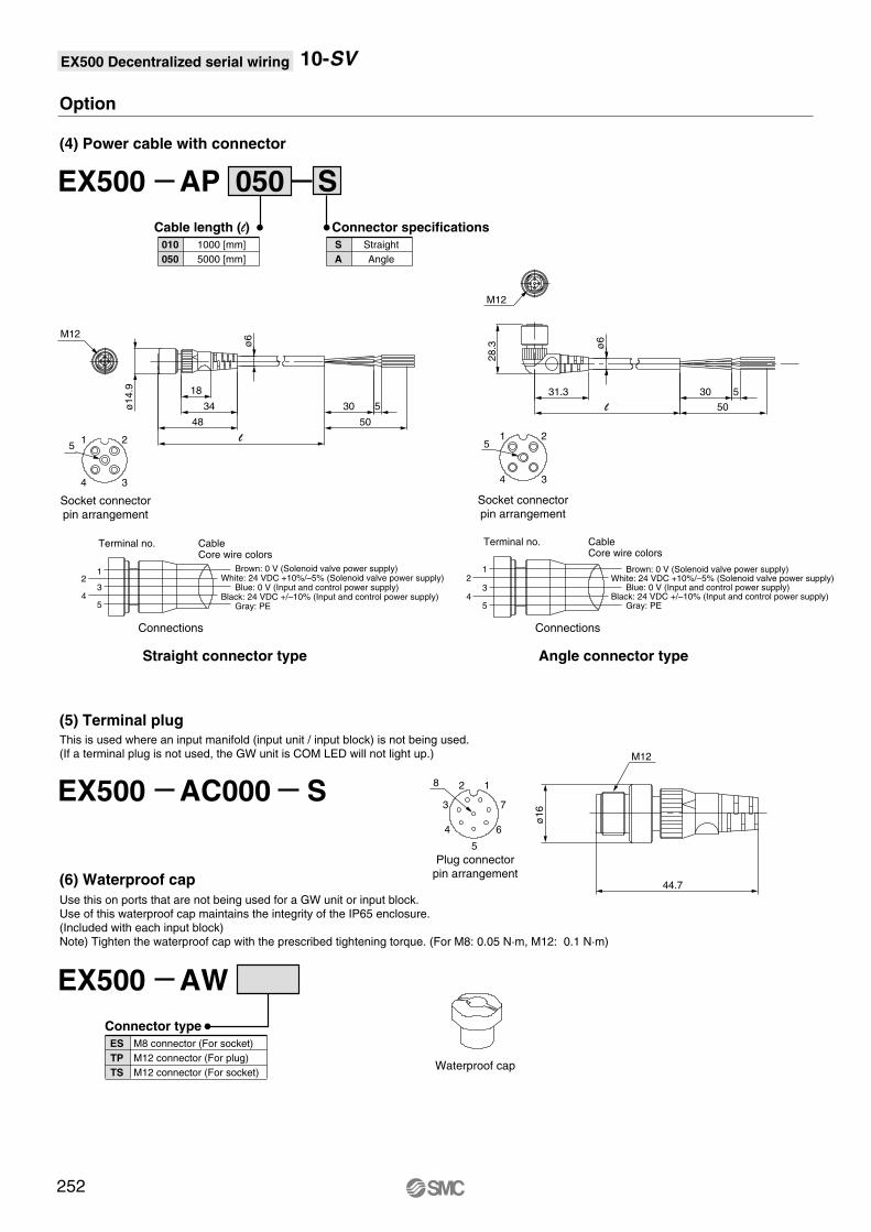
(4) Power cable with connector
Straight connector type Angle connector type
EX500 AP S050
010
050
Cable length (l)
1000 [mm]
5000 [mm]
S
A
Connector specifications
Straight
Angle
(6) Waterproof cap
EX500 AW
ES
TP
TS
Connector type
M8 connector (For socket)
M12 connector (For plug)
M12 connector (For socket)
(5) Terminal plugThis is used where an input manifold (input unit / input block) is not being used. (If a terminal plug is not used, the GW unit is COM LED will not light up.)
Use this on ports that are not being used for a GW unit or input block. Use of this waterproof cap maintains the integrity of the IP65 enclosure. (Included with each input block)Note) Tighten the waterproof cap with the prescribed tightening torque. (For M8: 0.05 N·m, M12: 0.1 N·m)
EX500 AC000 S
2
4 3
5
Socket connectorpin arrangement
1
12
34
5
White: 24 VDC +10%/–5% (Solenoid valve power supply)
Black: 24 VDC +/–10% (Input and control power supply)
Brown: 0 V (Solenoid valve power supply)
Blue: 0 V (Input and control power supply)
Gray: PE
Terminal no. CableCore wire colors
M12
ø1
4.9
48
34
18
l
ø6
30 5
50
Socket connectorpin arrangement
2
4 3
51
12
34
5
White: 24 VDC +10%/–5% (Solenoid valve power supply)
Black: 24 VDC +/–10% (Input and control power supply)
Brown: 0 V (Solenoid valve power supply)
Blue: 0 V (Input and control power supply)
Gray: PE
ConnectionsConnections
Terminal no. CableCore wire colors
M12
31.3
28
.3 ø6
30 5
50l
44.7
ø1
6
M12
Plug connectorpin arrangement
Waterproof cap
8 2
3
4
5
6
7
1
252
10-SV

Air c
ylin
der
Rota
ry a
ctu
ato
rA
ir g
ripper
Directional contr
ol
valv
eF
ittings &
Tubin
gP
ressure
sw
itch
Cle
an g
as filt
er
Flo
w c
ontr
ol
equip
ment
Filt
er,
Pre
ssure
contr
ol equip
ment
Air p
repara
tion
equip
ment
EX500 Decentralized serial wiring
With external pilot specifications
L1
L2
L3
L4
Ln 2
135.5
125
106.5
14.5
5
173
162.5
138
17.5
6
173
162.5
148.5
12.5
7
185.5
175
159
13.5
8
198
187.5
169.5
14.5
9
210.5
200
180
15.5
10
223
212.5
190.5
16.5
11
235.5
225
201
17.5
12
235.5
225
211.5
12
13
248
237.5
222
13
14
260.5
250
232.5
14
15
273
262.5
243
15
16
285.5
275
253.5
16
4
160.5
150
127.5
16.5
3
148
137.5
117
15.5
L Dimension n: Stations
A
B
A
B
A
B
A
B
A
B
C1
C2
AB
AB
DIN rail holding screw
(Pitch)
One-touch fitting
[1(P), 3/5(E) port]
Applicable tubing O.D.: ø8 ø5/16"
(Rail mounting hole pitch: 12.5)
Manual override
Press and turn for the locking type.( )
(Station n) (Station 1)
P1
5 3 E
P1
5 3 E
B
A
2
4
B
A
2
4
B
A
2
4
B
A
2
4
B
A
2
4
One-touch fitting
[4(A), 2(B) port]
Applicable tubing O.D.: ø3.2, ø1/8"
ø4, ø5/32"
ø6, ø1/4"
CO
MP
WR
2-M12
SI unit
U side D side
C1
C2P1
5 3 E
P1
5 3 E
B
A
2
4
B
A
2
4
B
A
2
4
B
A
2
4
B
A
2
4
One-touch fitting
[X: External pilot port]
Applicable tubing O.D.: ø4ø5/32" ø5/32"
One-touch fitting
[PE: Pilot EXH port]
Applicable tubing O.D.: ø4
Light/surge voltage suppressor
Block separation lever
PE
X
PE
X
(4.9
)
8
35
L3
(C6
:3.2
)(N
7:7
)
83.7
92.2
19
.7
48
63
7.5
11.8
L1
68.2
10
12
.6
23
28.6
22.3
P=10.5 13.5 46.7
29.2
52
.7
5.5
18
28.8
L2 5
42.3
(L4)
45
.5
59
26
.29
.5
58
.43
6.9
18.1 8.4
4(A) port side: Orange2(B) port side: Green
· When P, E port outlets are indicated on the U side or D side, the P, E ports on the opposite side are plugged.
· External pilot port positions are the same as P, E port outlet positions.
With option
78
41
4
2
A
B
4
2
A
B
4
2
A
B
4
2
A
B
E3/5
1 P
Individual SUP spacer
Individual EXH spacer
E3/5
1 P
E 3 P 1 E 3 P 1
Dimensions: Series 10-SV1000 for EX500 Decentralized serial wiring
253
10-SV
UDB
C3, N1C4, N3C6, N7
• Cassette base manifold: 10-SS5V1-W16SA WD- (R)-Stations

EX500 Decentralized serial wiring
With external pilot specifications
Dimensions: Series 10-SV2000 for EX500 Decentralized serial wiring
L1
L2
L3
L4
Ln 2
148
137.5
122.5
13
5
198
187.5
170.5
14
6
210.5
200
186.5
12
7
235.5
225
202.5
16.5
8
248
237.5
218.5
15
9
260.5
250
234.5
13
10
285.5
275
250.5
17.5
11
298
287.5
266.5
16
12
310.5
300
282.5
14
13
323
312.5
298.5
12.5
14
348
337.5
314.5
17
15
360.5
350
330.5
15
16
373
362.5
346.5
13.5
4
185.5
175
154.5
15.5
3
173
162.5
138.5
17.5
L Dimension n: Stations
· When P, E port outlets are indicated on the U side or D side, the P, E ports on the opposite side are plugged.
· External pilot port positions are the same as P, E port outlet positions.
(Station n) (Station 1)
(Rail mounting hole pitch: 12.5)
One-touch fitting
[1(P), 3/5(E) port]Applicable tubing O.D.: ø10
ø3/8"
One-touch fitting
[4(A), 2(B) port]Applicable tubing O.D.: ø4, ø5/32"
ø6, ø1/4"ø8, ø5/16"
2-M12
(Pitch)
DIN rail holding screw
SI unit
U side D side
One-touch fitting
[PE: Pilot EXH port]Applicable tubing O.D.: ø4
ø5/32"
One-touch fitting
[X: External pilot port]Applicable tubing O.D.: ø4
ø5/32"
Light/surge voltage suppressor
Block separation lever
19
.7
56
.571.5
7.5
68.2
L2
L1
5
5.5
27
.3
39.5
35
8
43
.14
2.3
69.1
26
.29
.5
L3 (L4)
23.5
12.5
15.9
31
.534.6
P=16 17.5 48
11.8
29.2
52.7
53.9
67
.5
18.8 9.5
(5.3
)
(4.9
)
44
.5
Manual override
Press and turn for the locking type.( )
4(A) port side: Orange2(B) port side: Green
11
5.5
10
2.9
With option
86
.5
50
.5
Individual SUP spacer
Individual EXH spacer
254
10-SV
UDB
C4, N3C6, N7C8, N9
• Cassette base manifold: 10-SS5V2-W16SA WD- (R)-Stations

Air c
ylin
der
Rota
ry a
ctu
ato
rA
ir g
ripper
Directional contr
ol
valv
eF
ittings &
Tubin
gP
ressure
sw
itch
Cle
an g
as filt
er
Flo
w c
ontr
ol
equip
ment
Filt
er,
Pre
ssure
contr
ol equip
ment
Air p
repara
tion
equip
ment
EX500 Decentralized serial wiring
With external pilot specifications
Dimensions: Series 10-SV1000 for EX500 Decentralized serial wiring
L1
L2
L3
L4
L5
Ln 2
135.5
125
102.6
16.5
63
5
160.5
150
134.1
13
94.5
6
173
162.5
144.6
14
105
7
185.5
175
155.1
15
115.5
8
198
187.5
165.6
16
126
9
210.5
200
176.1
17
136.5
10
210.5
200
186.6
12
147
11
223
212.5
197.1
13
157.5
12
235.5
225
207.6
14
168
13
248
237.5
218.1
15
178.5
14
260.5
250
228.6
16
189
15
273
262.5
239.1
17
199.5
16
273
262.5
249.6
11.5
210
4
148
137.5
123.6
12
84
3
148
137.5
113.1
17.5
73.5
L Dimension n: Stations
· When P, E port outlets are indicated on the U side or D side, the P, E ports on the opposite side are plugged.
· External pilot port positions are the same as P, E port outlet positions.
A
B
A
B
A
B
A
B
A
B
CO
MP
WRA
B
AB
(Rail mounting hole pitch: 12.5)
One-touch fitting
[1(P), 3/5(E) port]Applicable tubing O.D.: ø8
ø5/16"
E
1 P
35
B 2
A 4
B 2 B 2 B 2 B 2
A 4 A 4 A 4 A 4
DIN rail holding screw
(For DIN rail mounting)
(Station n) (Station 1)
(Pitch)
One-touch fitting
[4(A), 2(B) port]Applicable tubing O.D.: ø3.2, ø1/8"
ø4, ø5/32"
ø6, ø1/4"
1 P
5 3 E
SI unit
(For
DIN
rail
mounting)
2-M12
E
1 P
35
B 2
A 4
B 2 B 2 B 2 B 2
A 4 A 4 A 4 A 4
1 P
5 3 E
One-touch fitting
[PE: Pilot EXH port]Applicable tubing O.D.: ø4
ø5/32"
One-touch fitting
[X: External pilot port]Applicable tubing O.D.: ø4
ø5/32"
U side D side
4-ø4.3
(For mounting)
C1
C2
C1
C2
Light/surge voltage suppressor
PE
X
PE
X
(7.5
)
8
58.7
45.5
(4.9
)
P=10.5
10
23
L1
59.5
L5
83.7
(C6:3
.2)
(N7:7
)
46.9
8.6
24.6
18.3
92.2
10
19.7
43.2
11.8
13.5
L3
L2 5
(L4)
5.5
35
11.8
43
56.5
83
4.6
9.5
34.1
29.6
10.8
39.6
9.6
68.5
92.6
14.1 8.4
Manual override
Press and turn for the locking type.( )
4(A) port side: Orange2(B) port side: Green
37.5
74.5
4A
2B
4A
2B
4A
2B
4A
2B
Individual SUP spacer
Individual EXH spacer
E
P1
3/5E3/5
P1
P 1E 3 P 1E 3
With option
255
10-SV
UDB
C3, N1C4, N3C6, N7
• Tie-rod base manifold: 10-SS5V1-W10SA WD- (-D)(R)-Stations

EX500 Decentralized serial wiring
With external pilot specifications
Dimensions: Series 10-SV2000 for EX500 Decentralized serial wiring
L1
L2
L3
L4
L5
Ln 2
148
137.5
118
15
80
5
198
187.5
166
16
128
6
210.5
200
182
14.5
144
7
223
212.5
198
12.5
160
8
248
237.5
214
17
176
9
260.5
250
230
15.5
192
10
273
262.5
246
13.5
208
11
285.5
275
262
12
224
12
310.5
300
278
16.5
240
13
323
312.5
294
14.5
256
14
335.5
325
310
13
272
15
360.5
350
326
17.5
288
16
373
362.5
342
15.5
304
4
185.5
175
150
18
112
3
160.5
150
134
13.5
96
L Dimension n: Stations
· When P, E port outlets are indicated on the U side or D side, the P, E ports on the opposite side are plugged.
· External pilot port positions are the same as P, E port outlet positions.
(Station n) (Station 1)
DIN rail holding screw
(For DIN rail mounting)
(Rail mounting hole pitch: 12.5)
(Pitch)
One-touch fitting
[1(P), 3/5(E) port]Applicable tubing O.D.: ø10
ø3/8"
One-touch fitting
[4(A), 2(B) port]Applicable tubing O.D : ø4, ø5/32"
ø6, ø1/4"
ø8, ø5/16"
(Fo
r D
IN r
ail
mo
un
tin
g)
U side D side
4-ø5.3
(For mounting)
SI unit
One-touch fitting
[PE: Pilot EXH port]Applicable tubing O.D.: ø4
ø5/32"
One-touch fitting
[X: External pilot port]Applicable tubing O.D.: ø4
ø5/32"
2-M12
Light/surge voltage suppressor
12
52
.5
63
.5
59
.6
11
5.5
5.5
35
10
9.4
(4.9
)
(5.3
)
L5
L3 (L4)
L2
L1
5
20.5
9.2
25
.2
11.8
46.517.5P=16
11
.89
7.5
5.4
11
.9
30
.6 20
.6
44
.1
49
.9
63
.5
9.5
8
(7.5
)
321
0.7
68
.5
29
.61
2.2
53
.4
10
2.9
15.8 9.5
Manual override
Press and turn for the locking type.( )
4(A) port side: Orange2(B) port side: Green
With option
78.5 4
2.5
Individual EXH spacer
Individual SUP spacer
256
10-SV
UDB
C4, N3C6, N7C8, N9
• Tie-rod base manifold: 10-SS5V2-W10SA WD- (-D)(R)-Stations

Air c
ylin
der
Rota
ry a
ctu
ato
rA
ir g
ripper
Directional contr
ol
valv
eF
ittings &
Tubin
gP
ressure
sw
itch
Cle
an g
as filt
er
Flo
w c
ontr
ol
equip
ment
Filt
er,
Pre
ssure
contr
ol equip
ment
Air p
repara
tion
equip
ment
EX500 Decentralized serial wiring
With external pilot specifications
L1
L2
L3
L4
L5
Ln 2
160.5
150
135.1
12.5
97
5
223
212.5
196.6
13
158.5
6
248
237.5
217.1
15.5
179
7
273
262.5
237.6
17.5
199.5
8
285.5
275
258.1
13.5
220
9
310.5
300
278.6
16
240.5
10
323
312.5
299.1
12
261
11
348
337.5
319.6
14
281.5
12
373
362.5
340.1
16.5
302
13
385.5
375
360.6
12.5
322.5
14
410.5
400
381.1
14.5
343
15
435.5
425
401.6
17
363.5
16
448
437.5
422.1
13
384
4
210.5
200
176.1
17
138
3
185.5
175
155.6
15
117.5
L Dimension n: Stations
· When P, E port outlets are indicated on the U side or D side, the P, E ports on the opposite side are plugged.
· External pilot port positions are the same as P, E port outlet positions.
(Station n) (Station 1)
DIN rail holding screw
(For DIN rail mounting)
(Rail mounting hole pitch: 12.5)
(Pitch)
One-touch fitting
[1(P), 3/5(E) port]Applicable tubing O.D.: ø12
ø3/8"
One-touch fitting
[4(A), 2(B) port]Applicable tubing O.D.: ø6, ø1/4"
ø8, ø5/16"ø10,ø3/8"
2-M12
SI unit
(Fo
r D
IN r
ail
mo
un
tin
g)
4-ø5.3
(For mounting)
U side D side
One-touch fitting
[X: External pilot port]Applicable tubing O.D.: ø6
ø1/4"
One-touch fitting
[PE: Pilot EXH port]Applicable tubing O.D.: ø6
ø1/4"
Light/surge voltage suppressor
E
1 P
35
E
1 P
35
2 B
4 A
2 B
4 A
2 B
4 A
2 B
4 A
2 B
4 A
2 B
4 A
2 B
4 A
2 B
4 A
2 B
4 A
2 B
4 A
E
1 P
35
E
1 P
35
C1
C2
C1
C2
AB
A A A
BBBBB
A
CO
MP
WR
AB
A
X PE X PE
75
12
63
.882
.7
11
5.8
12
8.8
(L4)
L5
L3
L2
L1
5
6.5
5.5
11.848.621.3P=20.5
23.5
13
.5
36
.1
11
.6
36
37
.6
59
.5
8
83
.85
(5.1
)
(10
)
14
.7
35
60
.3
76
.8
14
.32
9.64
6.9
68
.51
0.1
9.5
31.6
(5.3
)
18 11
Manual override
Press and turn for the locking type.( )
4(A) port side: Orange2(B) port side: Green
With option
101.2
58.4
1
3/5
P1
E4 A
2 B
4 A
2 B
4 A
2 B
4 A
2 B
3/5
P1
E
Individual EXH spacer
Individual SUP spacer
5
3 E1
P
5
3 E1
P
1 1
Dimensions: Series 10-SV3000 Decentralized serial wiring
1
257
10-SV
UDB
C6, N7C8, N9C10, N11
• Tie-rod base manifold: 10-SS5V3-W10SA WD- (-D)(R)-Stations

EX500 Decentralized serial wiring
L1
L2
L3
L4
L5
Ln 2
173
162.5
145.6
13.5
109
5
248
237.5
217.6
15
181
6
273
262.5
241.6
15.5
205
7
298
287.5
265.6
16
229
8
323
312.5
289.6
16.5
253
9
348
337.5
313.6
17
277
10
373
362.5
337.6
17.5
301
11
385.5
375
361.6
12
325
12
410.5
400
385.6
12.5
349
13
435.5
425
409.6
13
373
14
460.5
450
433.6
13.5
397
15
485.5
475
457.6
14
421
16
510.5
500
481.6
14.5
445
4
223
212.5
193.6
14.5
157
3
198
187.5
169.6
14
133
L Dimension n: Stations
· When P, E port outlets are indicated on the U side or D side, the P, E ports on the opposite side are plugged.
· External pilot port positions are the same as P, E port outlet positions.
Dimensions: Series 10-SV4000 for EX500 Decentralized serial wiring
258
With option
With external pilot specifications(Pitch)
2-M12
U side D side
One-touch fitting
[X: External pilot port]Applicable tubing O.D.: ø6
ø1/4"
One-touch fitting
[PE: Pilot EXH port]Applicable tubing O.D.: ø6
ø1/4"
(For
DIN
rai
l mou
ntin
g)
Light/surge voltage suppressor
(Station n) (Station 1)
(Rail mounting hole pitch: 12.5)
SI unit
DIN rail holding screw
(For DIN rail mounting)
4-ø6.2
(For mounting)
One-touch fitting
[1(P), 3/5(E) port]Applicable tubing O.D.: ø12
ø3/8"
One-touch fitting
[4(A), 2(B) port]Applicable tubing O.D: ø8, ø5/16"
ø10,ø3/8"ø12
1/4,3/8
[4(A), 2(B) port][F
or
Rc 1
/4,
3/8
]3/8
[1(P), 3/5(E) port]
14
.5
35
24P=24
40
.4
63
.9
61
.885
.5
79
.4
58
.3
74
.8
1125 11.848.6
16
.2
14
.7
(10
)
56
.3
29
.61
7.5
14
8.2
98
.2
16
4.7
5.5 3
5
68
.59
.5
81
.77
5
L2
L1
5
L5L3
30.1
(L4)
20
8
(5.4
)
13
.7
35
.8
13
.3
Manual override
Press and turn for the locking type.( )
4(A) port side: Orange2(B) port side: Green
105.5
58.5
Individual EXH spacer
Individual SUP spacer
10-SV
UDB
02,03,
N9,N11,
C8, C10, C12,
• Tie-rod base manifold: 10-SS5V4-W10SA WD- (-D)(R)-Stations
Air c
ylin
der
Rota
ry a
ctu
ato
rA
ir g
ripper
Directional contr
ol
valv
eF
ittings &
Tubin
gP
ressure
sw
itch
Cle
an g
as filt
er
Flo
w c
ontr
ol
equip
ment
Filt
er,
Pre
ssure
contr
ol equip
ment
Air p
repara
tion
equip
ment
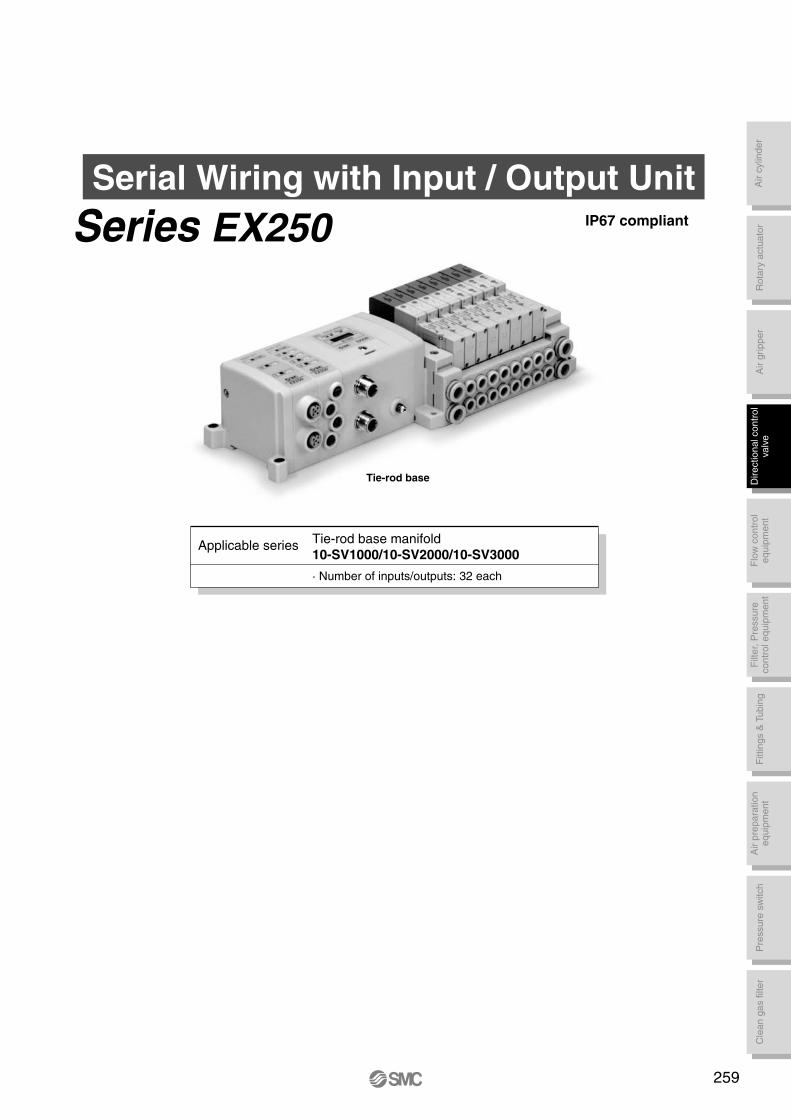
Serial Wiring with Input / Output UnitIP67 compliant
Tie-rod base
Applicable seriesTie-rod base manifold
10-SV1000/10-SV2000/10-SV3000
· Number of inputs/outputs: 32 each
259
Series EX250
• Tie-rod base
Enclosure
IP67 specifications
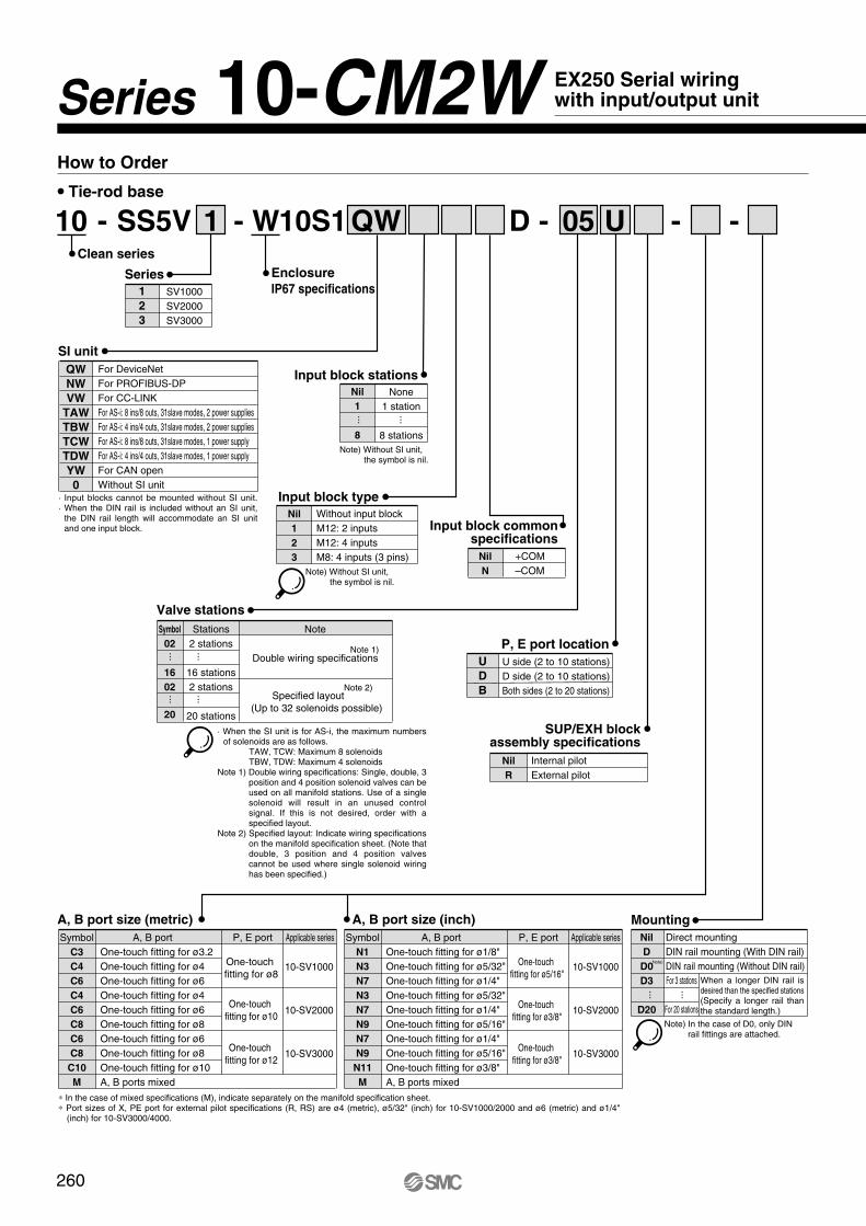
- - - -W D 0510S11 QW
Valve stations
Note
Double wiring specifications
Specified layout
(Up to 32 solenoids possible)
Symbol
02
16
02
20
Stations
2 stations
16 stations
2 stations
20 stations
None
1 station
8 stations
Series
1
2
3
SV1000
SV2000
SV3000
P, E port location
U
D
B
U side (2 to 10 stations)
D side (2 to 10 stations)
Both sides (2 to 20 stations)
···
···
···
···
Mounting
Direct mounting
DIN rail mounting (With DIN rail)
DIN rail mounting (Without DIN rail)
Nil
D
D0
D3
D20
For 3 stations
For 20 stations
···
···
Input block commonspecifications
+COM
–COM
Nil
N
Input block type
Without input block
M12: 2 inputs
M12: 4 inputs
M8: 4 inputs (3 pins)
Nil
1
2
3
SUP/EXH blockassembly specifications
Internal pilot
External pilot
Nil
R
Note 1)
Note 2)
U
Note) Without SI unit, the symbol is nil.
Input block stations
Nil
1
8
Note) Without SI unit, the symbol is nil.
···
···
Note) In the case of D0, only DIN rail fittings are attached.
Note)
· When the SI unit is for AS-i, the maximum numbers of solenoids are as follows.
TAW, TCW: Maximum 8 solenoids TBW, TDW: Maximum 4 solenoidsNote 1) Double wiring specifications: Single, double, 3
position and 4 position solenoid valves can be used on all manifold stations. Use of a single solenoid will result in an unused control signal. If this is not desired, order with a specified layout.
Note 2) Specified layout: Indicate wiring specifications on the manifold specification sheet. (Note that double, 3 position and 4 position valves cannot be used where single solenoid wiring has been specified.)
A, B port size (inch)
A, B portSymbol
N1
N3
N7
N3
N7
N9
N7
N9
N11
M
One-touch fitting for ø1/8"
One-touch fitting for ø5/32"
One-touch fitting for ø1/4"
One-touch fitting for ø5/32"
One-touch fitting for ø1/4"
One-touch fitting for ø5/16"
One-touch fitting for ø1/4"
One-touch fitting for ø5/16"
One-touch fitting for ø3/8"
A, B ports mixed
One-touch
fitting for ø5/16"
P, E port Applicable series
10-SV1000
10-SV2000
10-SV3000
One-touch
fitting for ø3/8"
One-touch
fitting for ø3/8"
A, B port size (metric)
A, B portSymbol
C3
C4
C6
C4
C6
C8
C6
C8
C10
M
One-touch fitting for ø3.2
One-touch fitting for ø4
One-touch fitting for ø6
One-touch fitting for ø4
One-touch fitting for ø6
One-touch fitting for ø8
One-touch fitting for ø6
One-touch fitting for ø8
One-touch fitting for ø10
A, B ports mixed
One-touch
fitting for ø8
P, E port Applicable series
10-SV1000
10-SV2000
10-SV3000
One-touch
fitting for ø10
One-touch
fitting for ø12
∗ In the case of mixed specifications (M), indicate separately on the manifold specification sheet. ∗ Port sizes of X, PE port for external pilot specifications (R, RS) are ø4 (metric), ø5/32" (inch) for 10-SV1000/2000 and ø6 (metric) and ø1/4"
(inch) for 10-SV3000/4000.
Clean series
SS5V
How to Order
-10
SI unit
For DeviceNet
For PROFIBUS-DP
For CC-LINK
For AS-i: 8 ins/8 outs, 31slave modes, 2 power supplies
For AS-i: 4 ins/4 outs, 31slave modes, 2 power supplies
For AS-i: 8 ins/8 outs, 31slave modes, 1 power supply
For AS-i: 4 ins/4 outs, 31slave modes, 1 power supply
For CAN open
Without SI unit
QW
NW
VW
TAW
TBW
TCW
TDW
YW
0· Input blocks cannot be mounted without SI unit.· When the DIN rail is included without an SI unit,
the DIN rail length will accommodate an SI unit and one input block.
260
EX250 Serial wiring with input/output unitSeries CM2W10-
When a longer DIN rail is desired than the specified stations(Specify a longer rail than the standard length.)
Air c
ylin
der
Rota
ry a
ctu
ato
rA
ir g
ripper
Directional contr
ol
valv
eF
ittings &
Tubin
gP
ressure
sw
itch
Cle
an g
as filt
er
Flo
w c
ontr
ol
equip
ment
Filt
er,
Pre
ssure
contr
ol equip
ment
Air p
repara
tion
equip
ment
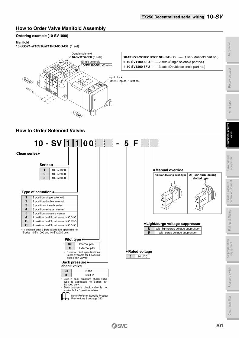
EX250 Decentralized serial wiring
How to Order Valve Manifold Assembly
Ordering example (10-SV1000)
Manifold10-SS5V1-W10S1QW11ND-05B-C6 (1 set)
10-SS5V1-W10S1QW11ND-05B-C6··········1 set (Manifold part no.)
10-SV1100-5FU··········2 sets (Single solenoid part no.)
10-SV1200-5FU··········3 sets (Double solenoid part no.)
Manual override
Rated voltage
Nil: Non-locking push type D: Push-turn locking
slotted type
-1 1 0 0 F5
5 24 VDC
Light/surge voltage suppressor
With light/surge voltage suppressor
With surge voltage suppressor
U
R
Pilot type
∗ External pilot specifications is not available for 4 position dual 3 port valves.
∗ 4 position dual 3 port valves are applicable to Series 10-SV1000 and 10-SV2000 only.
∗ Built-in back pressure check valve type is applicable to Series 10-SV1000 only.
∗ Back pressure check valve is not available for 3 position valves.
How to Order Solenoid Valves
Internal pilot
External pilot
Nil
R
Back pressure check valve
None
Built-in
Nil
K
Series
1
2
3
10-SV1000
10-SV2000
10-SV3000
Type of actuation
1
2
3
4
5
A
B
C
2 position single solenoid
2 position double solenoid
3 position closed center
3 position exhaust center
3 position pressure center
4 position dual 3 port valve: N.C./N.C.
4 position dual 3 port valve: N.O./N.O.
4 position dual 3 port valve: N.C./N.O.
Double solenoid
10-SV1200-5FU (3 sets)
Single solenoid
10-SV1100-5FU (2 sets)
Input block
(M12: 2 inputs, 1 station)
32
1
Stations
U side
D side
Note) Refer to Specific Product Precautions 2 on page 323.
SVClean series
-10
261
10-SV

EX250 Serial wiring with input/output unit
Series EX250 Serial Wiring with input/Output Unit 10-SV1000/2000/3000
Applicable network
Dimensions: SI unit / Input block
• The serial transmission system reduces wiring work, while minimizing wiring and saving space.
As a field bus slave, it is capable of solenoid valve ON/OFF control up to a maximum of 32 points.In addition, by connecting an input block a maximum of 32 sensor signal inputs are possible.
SI unit
This is an expansion block which connects to an SI unit to perform sensor input from auto switches, etc. Two or four sensor inputs can be accommodated by one input block, and the common can be matched to the sensor by an NPN/PNP switch.Input connectors are available in both M8 and M12 types.
Input block
DeviceNet / PROFIBUS-DP / CC-Link / AS-i / CANopen
DeviceNet, PROFIBIS-DP, CC-Link, CAN open compatible CC-LINK compatible Input block
AS-i compatible
A
MOD/NETPWR(V)
72.1
6
64.4
EX250
SIPWR
SETTINGS
0
1
Ground terminal
Communication connector
Power connector
63
PWR
BUS
59.8
L ERRL RUN
x 1 x 10
STATION NO.B RATE
PWPW(V)
LINK INLINK OUT
Bus adapter
PWR
Max.1
18
59.8
72.1
6
64.4
63
EX250
SI
Ground
terminal
Power
connector
ADDRESS SETTING
SW
EX250
ADDR2ADDR1
HOLD
CLEAR
COM-ERRIN
AUX-ERR
PWR
SI
75.1
72.1
6
64.4
Ground terminal
Communication connector
Power connector
63
PWR
BUS
59.8
ADDRESS SETTING
SW
EX250
ADDR2ADDR1
HOLD
CLEAR
COM-ERRIN
AUX-ERR
PWR
SI
75.164.4
Communication connector
63
BUS
59.8
1 power supply 2 power supplies
EX250
1
0
0
1
21
72.6
59.8
EX250-IE1EX250-IE2
EX250-IE3
EX250
0
1
2
3
0
1
2
3
21
67.4
59.8
1 2
3
54
1
34
No.
1
2
34
5
Function
Power supply (24 VDC)
Power supply (0 V)
Input
Ground
EX250-IE1
—
EX250-IE2
Input
No.
1
3
4
Function
Power supply (24 VDC)
Power supply (0 V)
Input
Compatible protocol
DeviceNet/CANopen
PROFIBUS-DP
A dimension
75.1
78.9
262
10-SV

Air c
ylin
der
Rota
ry a
ctu
ato
rA
ir g
ripper
Directional contr
ol
valv
eF
ittings &
Tubin
gP
ressure
sw
itch
Cle
an g
as filt
er
Flo
w c
ontr
ol
equip
ment
Filt
er,
Pre
ssure
contr
ol equip
ment
Air p
repara
tion
equip
ment
EX250 serial wiring with input/output unit
Dimensions: Series 10-SV1000 for EX250 Serial Wiring with Input/Output Unit
• Tie-rod base manifold: 10-SS5V1-W10S1 D-
0
1
2
3
4
5
6
7
8
stationsInput block
(n2)
Valve stations (n1) 2
L1: DIN rail overall length
· When P, E port outlets are indicated on the U side or D side, the P, E ports on the opposite side are plugged.
· External pilot port positions are the same as P, E port outlet positions.
185.5
210.5
223
248
273
285.5
310.5
335.5
348
3
198
210.5
235.5
260.5
273
298
323
348
360.5
4
210.5
223
248
273
285.5
310.5
335.5
348
373
5
210.5
235.5
260.5
273
298
323
348
360.5
385.5
6
223
248
273
285.5
310.5
335.5
348
373
398
7
235.5
260.5
273
298
323
348
360.5
385.5
410.5
8
248
273
285.5
310.5
335.5
348
373
398
410.5
9
260.5
273
298
323
348
360.5
385.5
410.5
423
10
273
285.5
310.5
335.5
348
373
398
410.5
435.5
11
273
298
323
348
360.5
385.5
410.5
423
448
12
285.5
310.5
335.5
348
373
398
410.5
435.5
460.5
13
298
323
348
360.5
385.5
410.5
423
448
473
14
310.5
335.5
348
373
398
410.5
435.5
460.5
473
15
323
348
360.5
385.5
410.5
423
448
473
485.5
16
335.5
348
373
398
410.5
435.5
460.5
473
498
17
348
360.5
385.5
410.5
423
448
473
485.5
510.5
18
348
373
398
410.5
435.5
460.5
473
498
523
19
360.5
385.5
410.5
423
448
473
485.5
510.5
535.5
20
373
398
410.5
435.5
460.5
473
498
523
535.5
(With 2 input blocks)
263
L2 = L1 – 10.5
L3 = 10.5 x n1 + 53
L4 = L3 + 81 + 21 x n2
L5 = (L1 – L4)/2
L6 = 10.5 x n1 + 42
L7 = 21 x n2 + 81
n1 = Valve stations
n2 = Input block stations
One-touch fitting
[1(P), 3/5(E) port]Applicable tubing O.D.:ø8
ø5/16"
DIN rail holding screw
(For DIN rail mounting)
(Station n1) (Station 1)
(Pitch)
One-touch fitting[4(A), 2(B) port]Applicable tubing O.D.: ø3.2, ø1/8"
ø4, ø5/32"ø6, ø1/4"
(Fo
r D
IN r
ail
mo
un
tin
g)
U side D side
SI unit Input block DIN rail holding screw
(For DIN rail mounting)
One-touch fitting
[X: External pilot port]Applicable tubing O.D.: ø4
ø5/32"
One-touch fitting
[PE: Pilot EXH port]Applicable tubing O.D.: ø4
ø5/32"
With external pilot specifications
(Station n2)(Station 1)
Light/surge voltage suppressor
2-M12
4-M8
2-M4 mounting hole
(Rail mounting hole pitch: 12.5)
(7.5
)
45
.5
(4.9
)
10
23
59
.5
L6
(C6
:3.2
)(N
7:7
)18.3
92
.2
10
11
.88
34
.6
8.6
24
.6
13.5 P=10.5
L2
L1
5
63 21
8
5.5
35
66
60
43
56
.5
14.1 8.4
39
.6
29
.61
0.8
83
.7
9.6
92
.6
18
L4L7 5.5
(L5)
L3
16.5
46.5
17.7
42
.7
Manual override
Press and turn for the locking type.( )4(A) port side: Orange2(B) port side: Green
End plate assembly
Individual SUP spacer
Individual EXH spacer
With option
37.5
74.5
4-ø4.3(For mounting)
10
.5
10-SV
(-D)UDB
C3, N1C4, N3C6, N7
(R)-Stations
Ground terminal
EX250 serial wiring with input/output unit
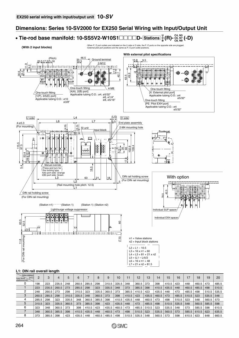
Dimensions: Series 10-SV2000 for EX250 Serial Wiring with Input/Output Unit
• Tie-rod base manifold: 10-SS5V2-W10S1D-
0
1
2
3
4
5
6
7
8
Input blockstations(n2)
Valve stations (n1) 2
L1: DIN rail overall length
· When P, E port outlets are indicated on the U side or D side, the P, E ports on the opposite side are plugged.
· External pilot port positions are the same as P, E port outlet positions.
198
223
248
260.5
285.5
310.5
323
348
373
3
223
235.5
260.5
285.5
298
323
348
360.5
385.5
4
235.5
260.5
273
298
323
335.5
360.5
385.5
398
5
248
273
298
310.5
335.5
360.5
373
398
423
6
260.5
285.5
310.5
335.5
348
373
398
410.5
435.5
7
285.5
298
323
348
360.5
385.5
410.5
435.5
448
8
298
323
335.5
360.5
385.5
398
423
448
460.5
9
310.5
335.5
360.5
373
398
423
435.5
460.5
485.5
10
335.5
348
373
398
410.5
435.5
460.5
473
498
11
348
373
385.5
410.5
435.5
448
473
498
510.5
12
360.5
385.5
410.5
423
448
473
485.5
510.5
535.5
13
373
398
423
435.5
460.5
485.5
510.5
523
548
14
398
410.5
435.5
460.5
473
498
523
535.5
560.5
15
410.5
435.5
448
473
498
510.5
535.5
560.5
573
16
423
448
473
485.5
510.5
535.5
548
573
598
17
448
460.5
485.5
510.5
523
548
573
585.5
610.5
18
460.5
485.5
498
523
548
560.5
585.5
610.5
623
19
473
498
510.5
535.5
560.5
585.5
598
623
648
20
485.5
510.5
535.5
548
573
598
610.5
635.5
660.5
(With 2 input blocks)
264
L2 = L1 – 10.5
L3 = 16 x n1 + 60
L4 = L3 + 81 + 21 x n2
L5 = (L1 – L4)/2
L6 = 16 x n1 + 48
L7 = 21 x n2 + 81.5
(Station n1) (Station 1)
DIN rail holding screw
(Rail mounting hole pitch: 12.5)
(Pitch)
One-touch fitting
[1(P), 3/5(E) port]Applicable tubing O.D.: ø10
ø3/8"
One-touch fitting
[4(A), 2(B) port]Applicable tubing O.D.: ø4, ø5/32"
ø6, ø1/4"ø8, ø5/16"
(Fo
r D
IN r
ail
mo
un
tin
g)
U side D side
4-ø5.3
(For mounting)
Light/surge voltage suppressor
SI unitInput block
End plate assembly
(Station 1) (Station n2)
One-touch fitting
[PE: Pilot EXH port]Applicable tubing O.D.: ø4
ø5/32"
One-touch fitting
[X: External pilot port]Applicable tubing O.D.: ø4
ø5/32"
With external pilot specifications
Ground terminal
2-M12
4-M8
12
52
.5
63
.51
15
.5
5.5
35
10
9.4
(4.9
)
(5.3
)
L6
5
20.5
9.2
25
.21
1.8
97
.55
.4
11
.9
30
.6
(7.5
)
29
.61
2.2
53
.4
10
2.9
17.5P=16
66
17
.4
L2
L1
L7
L46
05.5
15.8 9.5
49
.9
63
.5
21 18
17
.7
42
.7
16.5
46.5
(L5)
L3 63
Manual override
Press and turn for the locking type.( )
4(A) port side: Orange2(B) port side: Green
(For DIN rail mounting)
n1 = Valve stations
n2 = Input block stations
2-M4 mounting hole
DIN rail holding screw
(For DIN rail mounting)With option
78.5 4
2.5
Individual EXH spacer
Individual SUP spacer
18
.3
10-SV
UDB
C4, N3C6, N7C8, N9
Stations (R)- (-D)

Air c
ylin
der
Rota
ry a
ctu
ato
rA
ir g
ripper
Directional contr
ol
valv
eF
ittings &
Tubin
gP
ressure
sw
itch
Cle
an g
as filt
er
Flo
w c
ontr
ol
equip
ment
Filt
er,
Pre
ssure
contr
ol equip
ment
Air p
repara
tion
equip
ment
EX250 serial wiring with input/output unit
Dimensions: Series 10-SV3000 for EX250 Serial Wiring with Input/Output Unit
• Tie-rod base manifold: 10-SS5V3-W10S1D-
0
1
2
3
4
5
6
7
8
Input blockstations (n2)
Valve stations (n1) 2
L1: DIN rail overall length
L2 = L1 – 10.5
L3 = 20.5 x n1 + 70.5
L4 = L3 + 81 + 21 x n2
L5 = (L1 – L4)/2
L6 = 20.5 x n1 + 56
L7 = 21 x n2 + 83.5
· When P, E port outlets are indicated on the U side or D side, the P, E ports on the opposite side are plugged.
· External pilot port positions are the same as P, E port outlet positions.
223
248
260.5
285.5
310.5
323
348
373
385.5
3
248
260.5
285.5
310.5
323
348
373
385.5
410.5
4
260.5
285.5
310.5
323
348
373
385.5
410.5
435.5
5
285.5
310.5
323
348
373
385.5
410.5
435.5
448
6
298
323
348
373
385.5
410.5
435.5
448
473
7
323
348
360.5
385.5
410.5
435.5
448
473
498
8
348
360.5
385.5
410.5
423
448
473
498
510.5
9
360.5
385.5
410.5
423
448
473
485.5
510.5
535.5
10
385.5
410.5
423
448
473
485.5
510.5
535.5
548
11
410.5
423
448
473
485.5
510.5
535.5
548
573
12
423
448
473
485.5
510.5
535.5
548
573
598
13
448
473
485.5
510.5
535.5
548
573
598
610.5
14
473
485.5
510.5
535.5
548
573
598
610.5
635.5
15
485.5
510.5
535.5
548
573
598
610.5
635.5
660.5
16
510.5
535.5
548
573
598
610.5
635.5
660.5
673
17
535.5
548
573
598
610.5
635.5
660.5
673
698
18
548
573
598
610.5
635.5
660.5
673
698
723
19
573
585.5
610.5
635.5
660.5
673
698
723
735.5
20
585.5
610.5
635.5
648
673
698
723
735.5
760.5
(With 2 input blocks)
n1 = Valve stations
n2 = Input block stations
265
(Station n1) (Station 1)
DIN rail holding screw
(For DIN rail mounting)
(Rail mounting hole pitch: 12.5)
(Pitch)
One-touch fitting
[1(P), 3/5(E) port]Applicable tubing O.D: ø12
ø3/8"
(Fo
r D
IN r
ail
mo
un
tin
g)
4-ø5.3
(For mounting)
With external pilot specifications
U side D side
SI unitInput block
Ground terminal
2-M12
4-M8One-touch fitting
[4(A), 2(B) port]Applicable tubing O.D.: ø6, ø1/4"
ø8, ø5/16"ø10, ø3/8"
Light/surge voltage suppressor
(Station 1) (Station n2)
One-touch fitting
[X: External pilot port]Applicable tubing O.D.: ø6
ø1/4"
One-touch fitting
[PE: Pilot EXH port]Applicable tubing O.D.: ø6
ø1/4"
12
63
.882
.7
11
5.8
23.5
13
.5
36
.18
3.8
5
(5.1
)
(10
)
14
.7
63 21
21.3 P=20.5
11
.6
37
.6
14
.32
9.6
(5.3
)
16.5
46.5
L3 18
L4
46
.9
5.5
35
66
16.8
L6 L7 5.5
(L5)
L2
L1
12
8.8
12
8.8
17
.7
42
.7
60
60
.3
76
.8
18 11
8
5
Manual overridePress and turn for the locking type.( )4(A) port side: Orange2(B) port side: Green
DIN rail holding screw
(For DIN rail mounting)
End plate assembly
2-M4 mounting hole
With option
101.2
58.4
1
Individual EXH spacer
Individual SUP spacer 1 11
17
.8
10-SV
UDB
C6, N7C8, N9C10, N11
Stations (R)- (-D)

Air c
ylin
der
Rota
ry a
ctu
ato
rA
ir g
ripper
Directional contr
ol
valv
eF
ittings &
Tubin
gP
ressure
sw
itch
Cle
an g
as filt
er
Flo
w c
ontr
ol
equip
ment
Filt
er,
Pre
ssure
contr
ol equip
ment
Air p
repara
tion
equip
ment
Dedicated Output Serial Wiring
Series EX120
Applicable series
Cassette base manifold
10-SV1000/10-SV2000
Tie-rod base manifold
10-SV1000/10-SV2000/10-SV3000/10-SV4000
· Number of outputs: 16 points
Tie-rod base
Cassette base
267
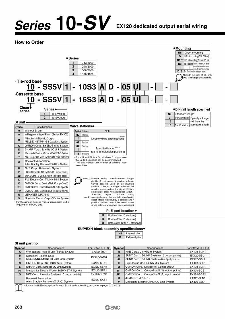
· Tie-rod base
·Cassette base
Series
-1 A
1
2
10-SV1000
10-SV2000
- - - -D 0516S31 A
SI unitValve stationsSpecifications
Without SI unit
With general type SI unit (Series EX300)
Mitsubishi Electric Corp.:MELSECNET/MINI-S3 Data Link System
OMRON Corp.: SYSBUS Wire System
SHARP Corp.: Satellite I/O Link System
Matsushita Electric Works: MEWNET-F System
NKE Corp.: Uni-wire System (16 point outputs)
Rockwell Automation:Allen Bradley Remote I/O (RIO) System
NKE Corp.: Uni-wire H System
SUNX Corp.: S-LINK System (16 output points)
SUNX Corp.: S-LINK System (8 output points)
Fuji Electric Co.: T-LINK Mini System
OMRON Corp.: DeviceNet, CompoBus/D
OMRON Corp.: CompoBus/S (16 output points)
OMRON Corp.: CompoBus/S (8 output points)
JEMANET (JPCN-1)
Mitsubishi Electric Corp.: CC-Link System
Symbol
0
A ∗
B
C
D
E
F1
G
H
J1
J2
K
Q
R1
R2
U
V
DIN rail length specified
Standard length
Specify a longer
rail than the
standard length.
Nil
3
16
Note
Double wiring specifications
Specified layout Note 2)
(up to 16 solenoids possible)
Symbol
02
08
02
16
Stations
2 stations
8 stations
2 stations
16 stations
Series
1
2
3
4
10-SV1000
10-SV2000
10-SV3000
10-SV4000
P, E port location
U
D
B
U side (2 to 10 stations)
D side (2 to 10 stations)
Both sides (2 to 16 stations)
……
……
For 3 stations
For 16 stations
… …
MountingDirect mounting
DIN rail mounting (With DIN rail)
DIN rail mounting (Without DIN rail)
When a longer DIN rail is desired than the specified stations(Specify a longer rail than the standard length.)
Nil
D
D0
D3
D16
For 3 stations
For 16 stations
… …
SUP/EXH block assembly specifications
Internal pilot
External pilot
Nil
R
Note 1)
Note) In the case of D0, only DIN rail fittings are attached.
- - -D 05 U10S3
U
Note)
Double wiring specifications: Single, double, 3 position and 4 position solenoid valves can be used on all manifold stations. Use of a single solenoid will result in an unused control signal. If this is not desired, order with a specified layout.Specified layout: Indicate wiring specifications on the manifold specification sheet. (Note that double, 3 position and 4 position valves cannot be used where single solenoid wiring has been specified.)
SI unit part no.
Specifications For SS5V-S3
EX320-S001
EX120-SMB1
EX120-STA1
EX120-SSH1
EX120-SPA1
EX120-SUW1
EX120-SAB1
For SS5V-S3
EX120-SUH1
EX120-SSL1
EX120-SSL2
EX120-SFU1
EX120-SDN1
EX120-SCS1
EX120-SCS2
EX120-SJN1
EX120-SMJ1
With general type SI unit (Series EX300)
Mitsubishi Electric Corp.:MELSECNET/MINI-S3 Data Link System
OMRON Corp.: SYSBUS Wire System
SHARP Corp.: Satellite I/O Link System
Matsushita Electric Works: MEWNET-F System
NKE Corp.: Uni-wire System (16 output points)
Rockwell Automation:Allen Bradley Remote I/O (RIO) System
Symbol
A ∗
B
C
D
E
F1
G
∗ For terminal LED descriptions for each SI unit and cable wiring, etc., refer to pages 270 to 272.
Specifications
NKE Corp.: Uni-wire H System
SUNX Corp.: S-LINK System (16 output points)
SUNX Corp.: S-LINK System (8 output points)
Fuji Electric Co.: T-LINK Mini System
OMRON Corp.: DeviceNet, CompoBus/D
OMRON Corp.: CompoBus/S (16 output points)
OMRON Corp.: CompoBus/S (8 output points)
JEMANET (JPCN-1)
Mitsubishi Electric Corp.: CC-Link System
Symbol
H
J1
J2
K
Q
R1
R2
U
V
SS5V
SS5VClean series
How to Order
-
-
10
10
268
EX120 dedicated output serial wiringSeries 10-SV
· Since J2 and R2 type SI units have 8 outputs note that up to 8 solenoids can be accommodated.
· This also includes the number of blanking plate assemblies.
Note 1)
Note 2)
∗ For the general purpose type, a transmission unit is required on the CPU side.

Air c
ylin
der
Rota
ry a
ctu
ato
rA
ir g
ripper
Directional contr
ol
valv
eF
ittings &
Tubin
gP
ressure
sw
itch
Cle
an g
as filt
er
Flo
w c
ontr
ol
equip
ment
Filt
er,
Pre
ssure
contr
ol equip
ment
Air p
repara
tion
equip
ment
EX120 dedicated output serial wiring
A, B port size (Inch)
A, B portSymbol
N1
N3
N7
N3
N7
N9
N7
N9
N11
N9
N11
02N
03N
02T
03T
M
One-touch fitting for ø1/8"
One-touch fitting for ø5/32"
One-touch fitting for ø1/4"
One-touch fitting for ø5/32"
One-touch fitting for ø1/4"
One-touch fitting for ø5/16"
One-touch fitting for ø1/4"
One-touch fitting for ø5/16"
One-touch fitting for ø3/8"
One-touch fitting for ø5/16"
One-touch fitting for ø3/8"
NPT 1/4
NPT 3/8
NPTF 1/4
NPTF 3/8
A, B ports mixed
∗ In the case of mixed specifications (M), indicate separately on the manifold specification sheet. ∗ Port sizes of X, PE port for external pilot specification (R) are ø4 (metric), ø5/32" (inch) for 10-SV1000/2000 and ø6 (metric) and ø1/4" (inch) for 10-SV3000/4000.
One-touch
fitting for ø5/16"
P, E port Applicable series
10-SV1000
10-SV2000
10-SV3000
10-SV4000
One-touch
fitting for ø3/8"
One-touch
fitting for ø3/8"
One-touch
fitting for ø3/8"
NPT3/8
NPTF3/8
A, B port size (Metric)
A, B portSymbol
C3
C4
C6
C4
C6
C8
C6
C8
C10
C8
C10
C12
02
03
02F
03F
M
One-touch fitting for ø3.2
One-touch fitting for ø4
One-touch fitting for ø6
One-touch fitting for ø4
One-touch fitting for ø6
One-touch fitting for ø8
One-touch fitting for ø6
One-touch fitting for ø8
One-touch fitting for ø10
One-touch fitting for ø8
One-touch fitting for ø10
One-touch fitting for ø12
Rc 1/4
Rc 3/8
G 1/4
G 3/8
A, B ports mixed
One-touch
fitting for ø8
P, E port Applicable series
10-SV1000
10-SV2000
10-SV3000
10-SV4000
One-touch
fitting for ø10
One-touch
fitting for ø12
One-touch
fitting for ø12
Rc3/8
G3/8
How to Order Valve Manifold Assembly
Ordering example (10-SV1000)
Manifold10-SS5V1-16S3AD-06B-C6 (1 set)
10-SS5V1-16S3AD-06B-C6··········1 set (Manifold part no.)
10-SV1100-5FU··········4 sets (Single solenoid part no.)
10-SV1200-5FU··········2 sets (Double solenoid part no.)
Manual override
Rated voltage
Nil: Non-locking push type D: Push-turn locking
slotted type
-1 1 0 0 F5
5 24 VDC
Light/surge voltage suppressor
With light/surge voltage suppressor
With surge voltage suppressor
U
RPilot type
∗ External pilot specification is not available for 4 position dual 3 port valves.
∗ 4 position dual 3 port valves are applicable to Series 10-SV1000 and 10-SV2000 only.
∗ Built-in back pressure check valve type is applicable to Series 10-SV1000 only.
∗ Back pressure check valve is not available for 3 position solenoid valves.
How to Order Solenoid Valves
Internal pilot
External pilot
Nil
R
Back pressure check valve
None
Built-in
Nil
K
Series
1
2
3
4
10-SV1000
10-SV2000
10-SV3000
10-SV4000
Type of actuation
1
2
3
4
5
A
B
C
2 position single solenoid
2 position double solenoid
3 position closed center
3 position exhaust center
3 position pressure center
4 position dual 3 port valve: N.C./N.C.
4 position dual 3 port valve: N.O./N.O.
4 position dual 3 port valve: N.C./N.O.
Double solenoid
10-SV1200-5FU (2 sets)
Single solenoid
10-SV1100-5FU (4 sets)
32
1
Stations
U side
D side
DD
DD
DD
Note) Refer to Specific Product Precautions 2 on page 323.
SVClean series
-10
269
10-SV

EX120 dedicated output serial wiring
Nam
e o
f te
rmin
al blo
ck,
LE
DN
ote
Ca
ble
wirin
g
Type A
Series EX300
Type B
Mitsubishi Electric Corporation
MELSECNET/MINI-S3 Data Link System
DescriptionLEDPOWER
RUNRDSD
ERR
ON for power supply inputON for normal data traffic with master unitON during data reception
ON during data transmissionON for data reception error, OFF when normal
DescriptionLEDTRD
RUN/ERRON during data reception
Blinks for normal data reception, ON for abnormal
•Connection to T unit PLC manufacturer's I/O · card enables serial transmission. EX300-TMB1 ··· for Mitsubishi Electric CorporationEX300-TTA1 ··· for OMROM CorporationEX300-TFU1 ··· for Fuji Electric Co., Ltd.EX300-T001 ··· General purpose∗ Each T unit has 32 control points.•No. of output points, 16 points
•MELSECNET/MINI-S3 Data Link System•Master unit: AJ71PT32-S3•AJ71T32-S3•A1SJ71PT32-S3•No. of output points, 16 points, No. of •stations occupied, 2 stations
SI manifold solenoid valve
∗ Ground either the reception side or the transmission side of the shielding wire shield.
∗ Ground either the reception side or the transmission side of the shielding wire shield.
Na
me
of te
rmin
al b
lock, L
ED
Note
Cable
wirin
g
Type C
OMRON Corporation
SYSBUS Wire System
Type D
SHARP Corporation
Satellite I/O Link System
Type E
Matsushita Electric Works, Ltd.
MEWNET-F System
DescriptionLEDPOWER
RUN
ERR
R.SET
HOLD
ON when power supply is ONON when power is ON and slave unit operates normally
ON for abnormal slave unit switch setting, abnormal communication, master unit PLC stopped and defective slave unit
ON for master unit control input
DescriptionLEDRUN
T / RERR
ON when transmission is normal and PLC is in operation modeBlinks when transmission is normal,
ON when transmission is abnormal.
DescriptionLEDPOWERCOMM.
ALARM
ON when power supply is ONBlinks during data transmission/receptionON for unit abnormality, blinks for station no. setting error
•Satellite I/O Link System•Master unit: ZW-31LM•JW-31LM,JW-31LMH•JW-23LM,JW-23LMH•No. of output points, 16 points
a) 2-wire typeWiring does not include signal ground line (SG).
b) 3-wire typeWiring does not include signal ground line (SG).
•SYSBUS Wire System•Master unit: Type C500-RM201•Type C200H-RM201•No. of output points, 16 points
•MEWNET-F System•Master unit: AFP3740, AFP3742•AFP5740, AFP5742•No. of output points, 16 points
Item Specifications
A,B,D,E,F1,J1,
J2,K,R1,R2,H,U,V
24 VDC +10%/–5%External power supply
Current consumption
(Internal unit)0.1A
0.3A C,Q
The serial transmission system reduces wiring work, while minimizing wiring and saving space.
Maximum 16 stations (Specify a model with more than 9 stations by means of the manifold specification sheet.)
· Stations are counted from D side as the 1st.· A maximum of 16 solenoids is possible (16 stations with single solenoids).
32
1
Stations
U side
D side
RUN T/R
ERR
DIP SW.
1
0
24V 0V + - + - FG
SDASDB SG RDARDB FG24V 0V
POWERRUNSD RD ERR
STATION NO.
x 10 x 1
POWERRUNERRR.SETHOLD
ADDRESS NO.
TERM.
24V 0V L1 L2 SG L1 L2 FG 24V 0V + - FG + - FG
POWER
STASTION NO.
TERM.
x 10 x 1 ONOFF
COMM.ALARM
24V 0V S1 S2 SG R1 R2 FG
RUNERR
TRD
ADDRESS NO.
S1
S2
SG
24V
0V
S1
S2
R1
R2
SG
FG
24V
0V
S1
S2
R1
R2
SG
FG
24V
0V
S1
S2
R1
R2
SG
FG
24V
0V
∗ ∗
SDA
SDB
RDA
RDB
SG
FG
SDA
SDB
RDA
RDB
SG
FG
SDA
SDB
RDA
RDB
SG
FG∗
SHIELDFG
SGL2
L1
SHIELDSGL2
L1
SHIELDSGL2
L1
SHIELDSGL2
L1
SHIELDFG
SGL2
L1
SHIELDSGL2
L1
SHIELDSGL2
L1
SHIELDSGL2
L1
–+
–+–+
FG
24V0V
–+–+
FG
24V0V
–
–
+
+FG–+
–
24V0V
+FG–+
–
24V0V
FG+
FG FG
T unit OB unit SI unit SI unit Master unit
Master unit SI unitMaster unit SI unit SI unit
Type 3 ground
Type 3 groundType 3 groundType 3 groundType 3 ground
Type 3 groundType 3 ground
Twisted pair wire with shield
Type 3 groundType 3 groundType 3 groundType 3 ground
Twisted pair wire with shield
Slave unit 75Slave unit 03Slave unit 01Master unitZW-31LM
Slave unit 75Slave unit 03Slave unit 01Master unitZW-31LM
Type 3 ground
SI unit
Remote I / O unit Remote I / O unit
DD
DD
DD
270
10-SV

Air c
ylin
der
Rota
ry a
ctu
ato
rA
ir g
ripper
Directional contr
ol
valv
eF
ittings &
Tubin
gP
ressure
sw
itch
Cle
an g
as filt
er
Flo
w c
ontr
ol
equip
ment
Filt
er,
Pre
ssure
contr
ol equip
ment
Air p
repara
tion
equip
ment
EX120 dedicated output serial wiring 10-SVN
am
e o
f te
rmin
al blo
ck,
LE
DN
ote
Ca
ble
wirin
g
Type F1
NKE Corporation
Uni-wire System
Type G
Allen Bradley Remote I/O (RIO) System
Type J1, J2
SUNX Corporation
S-LINK System
DescriptionLEDPOWER
COM
ERROR
ON when power supply is ON
ON when communication is normalBlinks when communication is initialized
OFF for abnormal communicationON for abnormal communication
DescriptionLED
POWER
SENDTransmission indication:
Blinks when normal, OFF or ON when abnormal
ON for power supply input(ON when normal, flickers when voltage drops)
DescriptionLEDPOWER
SEND
ON for power supply input
Transmission indication:Blinks when normal, Blinks slowly when abnormal
• Remote I/O (RIO) System
• No. of output points, 16 points
• Uni-wire System Send unit: SD-120
• No. of output points, 16 points
• S-LINK System S-LINK controller: SL-CU1A
• No. of output points, 16 points (Type J1) No. of output points (Type J2)
a) Type T branching multi-drop wiring (S-LINK System)
b) Crossover wiring (Sensor Link System)
Na
me
of te
rmin
al b
lock, L
ED
Note
Cable
wirin
g
Type K
Fuji Electric Co., Ltd.
T-LINK Mini System
Type Q
DeviceNet
Type R1, R2OMRON Corporation
CompoBus/S
DescriptionLEDPWR
MOD/
NET
Green light ON for DeviceNet circuit power inputOFF
Green blinks
Green ON
Red blinks
Red ON
When this unit is offline or circuit power is OFF
When waiting for connection (Online)
When connection is established (Online)
When connection time out occurs (recoverable communication abnormality)
For MAC ID duplication error, or BUSOFF error (major communication abnormality)
DescriptionLEDPOWER
ALM
ON for power supply input
ON for abnormal transmissionor processor side power supply cut
DescriptionLED
PWR
COMM
ERR
ON when communication power issupplied, OFF when power is OFF
ON for normal communication,OFF for abnormal communication or waiting
ON for abnormal communication,OFF for normal communication or waiting
• DeviceNet
• OMRON Corporation: CompoBus/D System Master unit: Type C200HW-DRM21-V1 Master unit: Type CS1W-DRM21• No. of output points, 16 points
• CompoBus/S System Master unit: Type C200HW-SRM21-V1 Master unit: Type CQM1-SRM21-V1
• No. of output points, 16 points (Type SR1) No. of output points, 8 points (Type SR2)
• T-LINK Mini System Master unit: FTM100B Converter: FRC100A-G02 Repeater: FRC200A-C10
• No. of output points, 16 points
24V 0V D G D G 0V
ADDRESSON
OFF
POWER SEND
24V 24V 0V L1 L2 SHILD L1 FG
ADDRESSON
OFF
POWER SEND
L2 G D 0V 24V G D 24V0V
POWER SEND
DIP SW.
1
0
24V 0V S1 S2 SD S1 FGS2
STATION NO.
TERM.
x 10 x 1 ON OFF
POWER ALM
BS+ BDH BDL BS- FG 24V 0V
ADDRESS NO.
PWR ERRCOMM 1
0
PWR MOD/NET
0
1SETTINGS
24V 0V V- CANL FG V+CANH
DG
Powersupply
24V0V
Powersupply
24V0V
Powersupply
24V0V
Powersupply
24V0V 0V
24V
0V24V
G
DG
D
0V24V
0V24V
G
DG
D
DG
Tra
nsm
issio
n lin
e
LINE1LINE2
SHIELD
L1L2
L1L2FG24V0V
SHIELD
L1 G
BlackWhite
BrownBlue
Main transmissionline
Transmission line
Crimped connector SL-J1A
D 0V 24V G D 0V 24V G D 0V 24V G D 0V 24VL2
L1L2FG24V0V
SHIELD
Terminalresistor
SI unit SI unitMaster unit
Type 3 groundType 3 ground
SD
FG
S2
S1
SD
FG
S2
S1
SD
FG
S2
S1
SD
FG
S2
S1
Type 3 ground Type 3 ground Type 3 ground
V-
BDH
Master unit
BDL
24V 0V V-
CANL
CANL
CANH
CANH
FG
FG BS+ BS- 24V 0VBDH BDL BS+ BS- 24V 0VBDH BDL
V+
V+ 24V 0V V- CANL CANHFG V+
Type 3 ground
Twisted pair wire with shield
Slave unit 75Slave unit 03Slave unit 01Master unit
Branch crimpedconnectors
Co
nn
ect
or
with
term
ina
l re
sist
or
271
Connect the shielding wire to the SD terminal. If the shielding wire is not connected to the SD terminal, normal transmission will be impossible even for short distances. Furthermore, do not ground the shielding wire (SD).
The above is the example of using dedicated S-LINK flat ribbon cable SL-RCMl00.

EX120 dedicated output serial wiring 10-SVN
am
e o
f te
rmin
al blo
ck,
LE
DN
ote
Ca
ble
wirin
g
Type H
NKE Corporation
Uni-wire H System
Type U
JEMANET (JPCN-1)
Type V
Mitsubishi Electric Corporation
CC-LINK System
DescriptionLEDPOWERCOMM
ON for SI unit power supply inputON for normal communication
ALARM ON for abnormal communication
DescriptionLED
POWER
SEND
ON for power supply input(ON when normal, flickers when voltage drops)
Transmission indication: Blinks when normal,OFF or ON when abnormal
DescriptionLEDPW
L RUNSDRD
L ERR.
ON when communication power is supplied, OFF when power is OFF
ON when data is transmittedON when data is received
ON for transmission error/wrong setting, Blinks when stationor transmission speed setting changes during operation
ON when normal data is being received
• JEMANET (JPCN-1) (Reference) AJ71J92-S3 (Mitsubishi Electric Corporation) A1SJ71J92-S3 (Mitsubishi Electric Corporation) Type C200HW-JRM21(OMRON Corporation) NJ-JPCN-1 (Fuji Electric Co., Ltd.) NP1L-JP1 (Fuji Electric Co., Ltd.)
• No. of output points, 16 points
a) 2-wire type
b) 3-wire type
• Uni-wire H System Send unit: SD-H2
• No. of output points, 16 points
• CC-Link System Master unit: AJ61BT11 Master unit: A1SJ61BT11 Master unit: AJ61QBT11 Master unit: A1SJ61QBT11
• No. of output points, 16 points
24V 0V A B SG FG 0V
ONPOWER ALARMCOMM
DIP.SW
24V24V 0V D G D G 0V24V
0
54
32
19
8
6
7
0
54
32
19
8
6
7
0
54
32
19
8
6
7
24V 0V +24V 24G DA DB FG
SD RDLERR.
STATION NO.
x 10 x 1
B RATE
PW LRUN
DG1 2 3 4 5 6 7 8
O N
ADDRESS
POWER SEND
ON
OFF
1
0
SLD
FG
DG
DB
DA
FG
DG
DB
DA
FG
DG
DB
DA
Master unit SI unit SI unit
Type 3 ground Type 3 groundType 3 ground Type 3 ground
Twisted pair wirewith shield
SG
B
A
Master unit (SI unit)
Twisted pair wire with shield
Twisted pair wirewith shield
FG
SG
B
A
FG
SG
B
A
FG
SG
B
A
FG
Slave unit(SI unit)
Slave unit(SI unit)
Slave unit
SG
B
A
Master unit (SI unit)
FG
Slave unit(SI unit)
Slave unit(SI unit)
Slave unit
SG
B
A
FG
SG
B
A
FG
SG
B
A
FG
Powersupply
24V0V
Powersupply
DG
DG
24V0V
Powersupply
24V0V
Powersupply
24V0VDGDG
24V0V
24V0VDGDG
24V0V
Tra
nsm
issio
n lin
e
Terminalresistor
Terminalresistor
24V0V
272
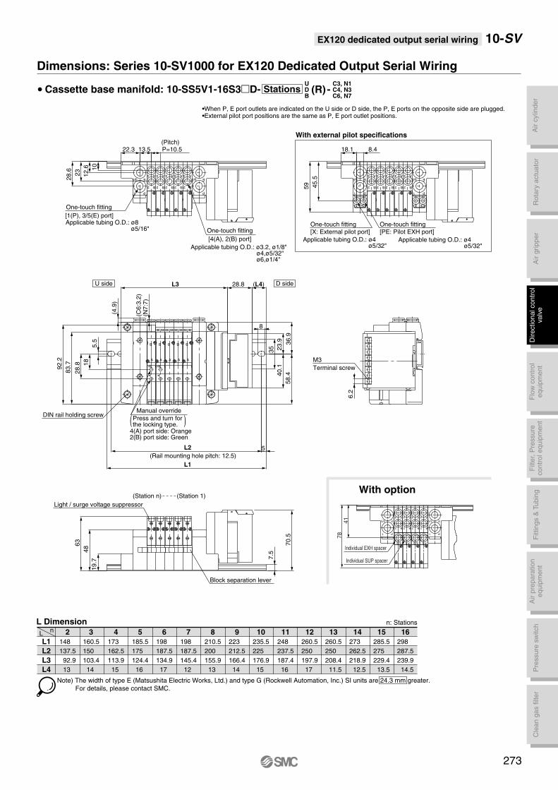
Air c
ylin
der
Rota
ry a
ctu
ato
rA
ir g
ripper
Directional contr
ol
valv
eF
ittings &
Tubin
gP
ressure
sw
itch
Cle
an g
as filt
er
Flo
w c
ontr
ol
equip
ment
Filt
er,
Pre
ssure
contr
ol equip
ment
Air p
repara
tion
equip
ment
EX120 dedicated output serial wiring 10-SV
UDB
C3, N1C4, N3C6, N7
Dimensions: Series 10-SV1000 for EX120 Dedicated Output Serial Wiring
Stations• Cassette base manifold: 10-SS5V1-16S3D- (R) -
L1
L2
L3
L4
Ln 2
148
137.5
92.9
13
5
185.5
175
124.4
16
6
198
187.5
134.9
17
7
198
187.5
145.4
12
8
210.5
200
155.9
13
9
223
212.5
166.4
14
10
235.5
225
176.9
15
11
248
237.5
187.4
16
12
260.5
250
197.9
17
13
260.5
250
208.4
11.5
14
273
262.5
218.9
12.5
15
285.5
275
229.4
13.5
16
298
287.5
239.9
14.5
4
173
162.5
113.9
15
3
160.5
150
103.4
14
L Dimension n: Stations
Note) The width of type E (Matsushita Electric Works, Ltd.) and type G (Rockwell Automation, Inc.) SI units are 24.3 mm greater.
For details, please contact SMC.
•When P, E port outlets are indicated on the U side or D side, the P, E ports on the opposite side are plugged. •External pilot port positions are the same as P, E port outlet positions.
A
B
A
B
A
B
A
B
A
B
AB
AB
DIN rail holding screw
(Pitch)
One-touch fitting
[1(P), 3/5(E) port]Applicable tubing O.D.: ø8
ø5/16"
(Rail mounting hole pitch: 12.5)
(Station n) (Station 1)
P1
5 3 E
P1
5 3 E
B
A
2
4
B
A
2
4
B
A
2
4
B
A
2
4
B
A
2
4
One-touch fitting
[4(A), 2(B) port]
Applicable tubing O.D.: ø3.2, ø1/8"ø4,ø5/32"ø6,ø1/4"
U side D side
P1
5 3 E
P1
5 3 E
B
A
2
4
B
A
2
4
B
A
2
4
B
A
2
4
B
A
2
4
One-touch fitting
[X: External pilot port]
Applicable tubing O.D.: ø4ø5/32"
One-touch fitting
[PE: Pilot EXH port]
Applicable tubing O.D.: ø4ø5/32"
M3
Terminal screw
Light / surge voltage suppressor
Block separation lever
With external pilot specifications
PE
X
PE
X
(4.9
)
(C6
:3.2
)(N
7:7
)
83
.7
92.2
19
.7
486
3
7.5
10
12
.6
23
28.6
22.3
5.5
45
.5
59
18.1 8.4
58
.43
6.9
23
.94
0.1
35
8
28.8 1
8
L2
L1
5
(L4)
6.2
13.5 P=10.5
L3 28.870.5
Manual override
Press and turn forthe locking type.( )
78
41
4
2
A
B
4
2
A
B
4
2
A
B
4
2
A
B
E3/5
1 P
Individual SUP spacer
Individual EXH spacer
E3/5
1 P
E 3 P 1 E 3 P 1
With option
273
4(A) port side: Orange2(B) port side: Green
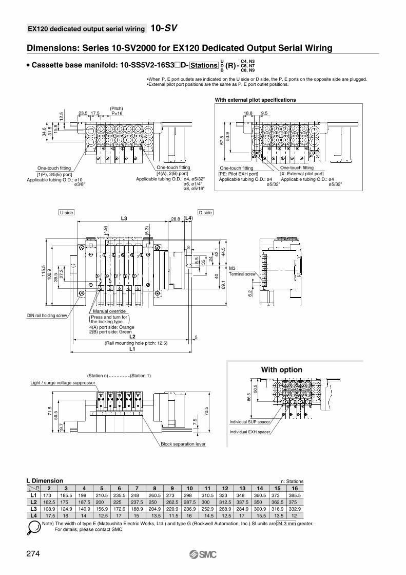
EX120 dedicated output serial wiring 10-SV
Dimensions: Series 10-SV2000 for EX120 Dedicated Output Serial Wiring
• Cassette base manifold: 10-SS5V2-16S3D-
L1
L2
L3
L4
Ln 2
173
162.5
108.9
17.5
5
210.5
200
156.9
12.5
6
235.5
225
172.9
17
7
248
237.5
188.9
15
8
260.5
250
204.9
13.5
9
273
262.5
220.9
11.5
10
298
287.5
236.9
16
11
310.5
300
252.9
14.5
12
323
312.5
268.9
12.5
13
348
337.5
284.9
17
14
360.5
350
300.9
15.5
15
373
362.5
316.9
13.5
16
385.5
375
332.9
12
4
198
187.5
140.9
14
3
185.5
175
124.9
16
L Dimension n: Stations
Note) The width of type E (Matsushita Electric Works, Ltd.) and type G (Rockwell Automation, Inc.) SI units are 24.3 mm greater.
For details, please contact SMC.
•When P, E port outlets are indicated on the U side or D side, the P, E ports on the opposite side are plugged. •External pilot port positions are the same as P, E port outlet positions.
274
(Station n) (Station 1)
(Rail mounting hole pitch: 12.5)
One-touch fitting
[1(P), 3/5(E) port]Applicable tubing O.D.: ø10
ø3/8"
One-touch fitting
[4(A), 2(B) port]
Applicable tubing O.D.: ø4, ø5/32"ø6, ø1/4"ø8, ø5/16"
(Pitch)
DIN rail holding screw
With external pilot specifications
U side D side
M3
Terminal screw
One-touch fitting
[PE: Pilot EXH port]Applicable tubing O.D.: ø4
ø5/32"
One-touch fitting
[X: External pilot port]
Applicable tubing O.D.: ø4ø5/32"
Light / surge voltage suppressor
Block separation lever
19
.7
56
.571
.5
27.3
39
.5
10
2.9
11
5.5
23.5
12
.5
15
.9
31.5
34
.6
7.5
L2
L1
5
8
5.5
35
(L4)
17.5 P=16
6.2
53.9
67.5
(5.3
)
18.8 9.5
L3 28.84
0
24
69.1
43.1
70
.5
(4.9
)
44.5
Manual override
Press and turn for the locking type.( )
4(A) port side: Orange2(B) port side: Green
86
.5
50
.5
Individual SUP spacer
Individual EXH spacer
With option
UDB
C4, N3C6, N7C8, N9
Stations (R) -
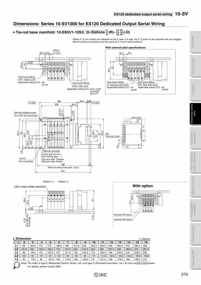
Air c
ylin
der
Rota
ry a
ctu
ato
rA
ir g
ripper
Directional contr
ol
valv
eF
ittings &
Tubin
gP
ressure
sw
itch
Cle
an g
as filt
er
Flo
w c
ontr
ol
equip
ment
Filt
er,
Pre
ssure
contr
ol equip
ment
Air p
repara
tion
equip
ment
EX120 dedicated output serial wiring 10-SV
Dimensions: Series 10-SV1000 for EX120 Dedicated Output Serial Wiring
• Tie-rod base manifold: 10-SS5V1-10S3D-
Note) The width of type E (Matsushita Electric Works, Ltd.) and type G (Rockwell Automation, Inc.) SI units are 24.3 mm greater.
For details, please contact SMC.
•When P, E port outlets are indicated on the U side or D side, the P, E ports on the opposite side are plugged. •External pilot port positions are the same as P, E port outlet positions.
L1
L2
L3
L4
L5
Ln 2
148
137.5
89
15
63
5
173
162.5
120.5
12
94.5
6
185.5
175
131
13
105
7
198
187.5
141.5
14
115.5
8
210.5
200
152
15
126
9
223
212.5
162.5
16
136.5
10
235.5
225
173
17
147
11
235.5
225
183.5
11.5
157.5
12
248
237.5
194
12.5
168
13
260.5
250
204.5
13.5
178.5
14
273
262.5
215
14.5
189
15
285.5
275
225.5
15.5
199.5
16
298
287.5
236
16.5
210
4
173
162.5
110
17
84
3
160.5
150
99.5
16
73.5
L Dimension n: Stations
A
B
A
B
A
B
A
B
A
B
AB
AB
(Rail mounting hole pitch: 12.5)
One-touch fitting
[1(P), 3/5(E) port]Applicable tubing O.D.: ø8
ø5/16"
E
1 P
35
B 2
A 4
B 2 B 2 B 2 B 2
A 4 A 4 A 4 A 4
DIN rail holding screw
(For DIN rail mounting)
(Station n) (Station 1)
(Pitch)
One-touch fitting
[4(A), 2(B) port]Applicable tubing O.D: ø3.2, ø1/8"
ø4,ø5/32"ø6,ø1/4"
1 P
5 3 E
U side D side
4-ø4.3
(For mounting)
(For
DIN
rail
mo
un
tin
g)
E
1 P
35
B 2
A 4
B 2 B 2 B 2 B 2
A 4 A 4 A 4 A 4
1 P
5 3 E
One-touch fitting
[PE: Pilot EXH port]Applicable tubing O.D.: ø4
ø5/32"
One-touch fitting
[X: External pilot port]Applicable tubing O.D.: ø4
ø5/32"
With external pilot specifications
M3
Terminal screw
Light / surge voltage suppressor
PE
X
PE
X
(7.5
)
Manual override
45.5
10
23
59
.5
L5
83
.7
18.3
92.2
10
11
.8
83
4.6
(C6
:3.2
)(N
7:7
)
(4.9
)
43
56.5
8
5.5
35
L2
L1
5
(L4)
13.5 P=10.5
6.2
8.6
24.6
29
.61
0.8
39
.6
11.8
64
92
.6
14.1 8.4
L3 28.8
20.5
61
Press and turn for the locking type.( )
4(A) port side: Orange2(B) port side: Green
37
.57
4.5
4A
2B
4A
2B
4A
2B
4A
2B
Individual SUP spacer
Individual EXH spacer
E
P1
3/5E3/5
P1
P 1E 3 P 1E 3
With option
275
UDB
C3, N1C4, N3C6, N7
Stations (R) - (-D)
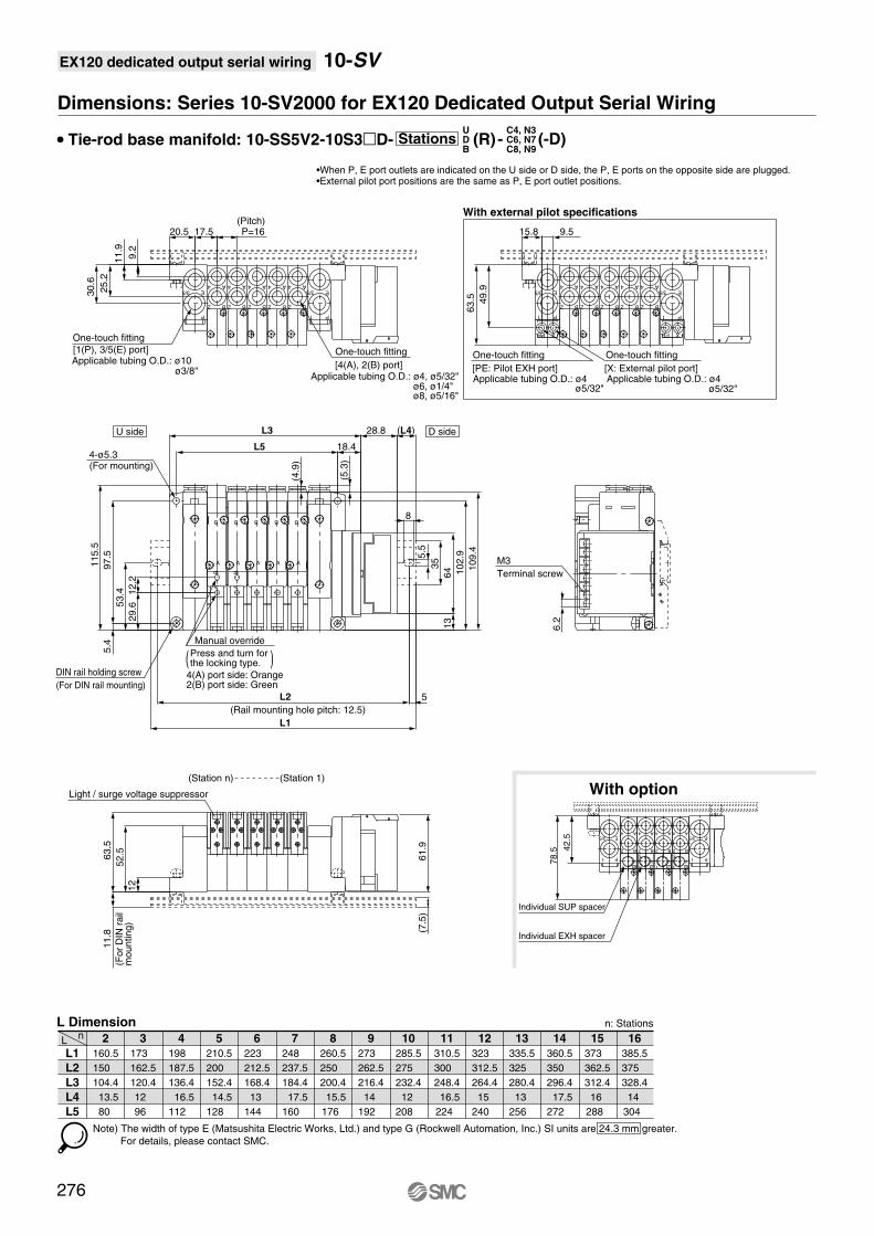
EX120 dedicated output serial wiring 10-SV
Dimensions: Series 10-SV2000 for EX120 Dedicated Output Serial Wiring
• Tie-rod base manifold: 10-SS5V2-10S3D-
L1
L2
L3
L4
L5
Ln 2
160.5
150
104.4
13.5
80
5
210.5
200
152.4
14.5
128
6
223
212.5
168.4
13
144
7
248
237.5
184.4
17.5
160
8
260.5
250
200.4
15.5
176
9
273
262.5
216.4
14
192
10
285.5
275
232.4
12
208
11
310.5
300
248.4
16.5
224
12
323
312.5
264.4
15
240
13
335.5
325
280.4
13
256
14
360.5
350
296.4
17.5
272
15
373
362.5
312.4
16
288
16
385.5
375
328.4
14
304
4
198
187.5
136.4
16.5
112
3
173
162.5
120.4
12
96
L Dimension n: Stations
Note) The width of type E (Matsushita Electric Works, Ltd.) and type G (Rockwell Automation, Inc.) SI units are 24.3 mm greater.
For details, please contact SMC.
•When P, E port outlets are indicated on the U side or D side, the P, E ports on the opposite side are plugged. •External pilot port positions are the same as P, E port outlet positions.
UDB
C4, N3C6, N7C8, N9
Stations (R) - (-D)
P1
E3/5
1 P
E3/5
B
A
2
4
B
A
2
4
B
A
2
4
B
A
2
4
B
A
2
4
(Station n) (Station 1)
DIN rail holding screw
(For DIN rail mounting)
(Rail mounting hole pitch: 12.5)
(Pitch)
One-touch fitting
[1(P), 3/5(E) port]Applicable tubing O.D.: ø10
ø3/8"
One-touch fitting
[4(A), 2(B) port]Applicable tubing O.D.: ø4, ø5/32"
ø6, ø1/4"ø8, ø5/16"
A
B
AB
AB
(For
DIN
rail
mo
un
tin
g)
U side D side
4-ø5.3(For mounting)
P1
E3/5
1 P
E3/5
B
A
2
4
B
A
2
4
B
A
2
4
B
A
2
4
B
A
2
4
One-touch fitting
[PE: Pilot EXH port]Applicable tubing O.D.: ø4
ø5/32"
One-touch fitting
[X: External pilot port]Applicable tubing O.D.: ø4
ø5/32"
With external pilot specifications
M3
Terminal screw
B
A
B
A
B
A
B
A
Light / surge voltage suppressor
PE
X
PE
X
12
52
.563.5
(7.5
)
11
5.5
(4.9
)
(5.3
)
L5
20.5
9.2
25.2
11
.85
.411.9
30.6
49.9
63
.5
15.8 9.517.5 P=16
(L4)
97
.5 5.5
35
8
L2 5
L1
6.22
9.6
12.2
13
64 1
09.4
53.4
L3 28.8
18.4
10
2.9
61.9
Manual override
Press and turn for the locking type.( )
4(A) port side: Orange2(B) port side: Green
78
.5 42
.5
4
2
A
B
4
2
A
B
4
2
A
B
4
2
A
B
3/5 E
1 P
Individual EXH spacer
Individual SUP spacer
V
5
3 E
E
P1
3/5
V
1 P
V
5
3 E
V
1 P
With option
276

Air c
ylin
der
Rota
ry a
ctu
ato
rA
ir g
ripper
Directional contr
ol
valv
eF
ittings &
Tubin
gP
ressure
sw
itch
Cle
an g
as filt
er
Flo
w c
ontr
ol
equip
ment
Filt
er,
Pre
ssure
contr
ol equip
ment
Air p
repara
tion
equip
ment
EX120 dedicated output serial wiring 10-SV
Dimensions: Series 10-SV3000 for EX120 Dedicated Output Serial Wiring
• Tie-rod base manifold: 10-SS5V3-10S3D-UDB
C6, N7C8, N9C10, N11
Stations (R) - (-D)
Note) The width of type E (Matsushita Electric Works, Ltd.) and type G (Rockwell Automation, Inc.) SI units are 24.3 mm greater.
For details, please contact SMC.
•When P, E port outlets are indicated on the U side or D side, the P, E ports on the opposite side are plugged. •External pilot port positions are the same as P, E port outlet positions.
L1
L2
L3
L4
L5
Ln 2
185.5
175
121.5
17.5
97
5
235.5
225
183
12
158.5
6
260.5
250
203.5
14
179
7
285.5
275
224
16.5
199.5
8
298
287.5
244.5
12.5
220
9
323
312.5
265
14.5
240.5
10
348
337.5
285.5
17
261
11
360.5
350
306
13
281.5
12
385.5
375
326.5
15
302
13
410.5
400
347
17.5
322.5
14
423
412.5
367.5
13.5
343
15
448
437.5
388
15.5
363.5
16
460.5
450
408.5
11.5
384
4
223
212.5
162.5
16
138
3
198
187.5
142
13.5
117.5
L Dimension n: Stations
(Station n) (Station 1)
DIN rail holding screw
(For DIN rail mounting)
(Rail mounting hole pitch: 12.5)
(Pitch)
One-touch fitting
[1(P), 3/5(E) port]Applicable tubing O.D.: ø12
ø3/8"
(For
DIN
rail
mo
un
tin
g)
4-ø5.3
(For mounting)
U side D side
M3
Terminal screw
One-touch fitting
[4(A), 2(B) port]Applicable tubing O.D.: ø6, ø1/4"
ø8,ø5/16"ø10,ø3/8"
One-touch fitting
[X: External pilot port]Applicable tubing O.D.: ø6
ø1/4"
One-touch fitting
[PE: Pilot EXH port]Applicable tubing O.D.: ø6
ø1/4"
Light / surge voltage suppressor
A
B
A
B
A
B
AB
A
B
AB
A
B
E
1 P
35
2 B
4 A
2 B
4 A
2 B
4 A
2 B
4 A
2 B
4 AE
1 P
35 E
1 P
35
2 B
4 A
2 B
4 A
2 B
4 A
2 B
4 A
2 B
4 AE
1 P
35
X PE X PE
With external pilot specifications
12
63.882.7
11
5.8
12
8.8
L5
23.5
13.5
36.1
83.8
5
(5.1
)
(10
)
14
.7
L2
L1
5
8
5.5
35
64
(L4)
11
.6
37.6
21.3 P=20.5
6.2
60.3
76.8
14.3
29.64
6.9
(5.3
)
18 11
L3 28.8
18
12
.3
77
.3
Manual override
Press and turn for the locking type.( )
4(A) port side: Orange2(B) port side: Green
10
1.2
58
.4
1 1
3/5
P1
E4 A
2 B
4 A
2 B
4 A
2 B
4 A
2 B
3/5
P1
E
Individual EXH spacer
Individual SUP spacer
5
3 E1
P
5
3 E1
P
1 1
With option
277
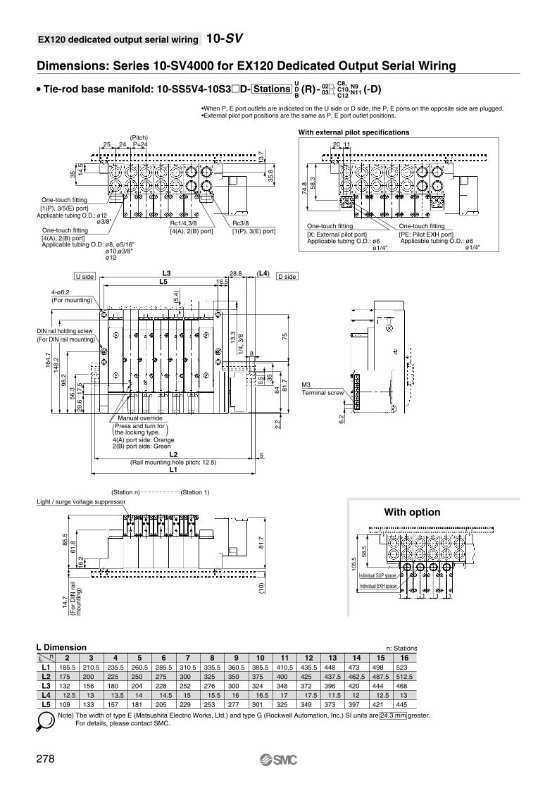
EX120 dedicated output serial wiring 10-SV
Dimensions: Series 10-SV4000 for EX120 Dedicated Output Serial Wiring
• Tie-rod base manifold: 10-SS5V4-10S3D-
L1
L2
L3
L4
L5
Ln 2
185.5
175
132
12.5
109
5
260.5
250
204
14
181
6
285.5
275
228
14.5
205
7
310.5
300
252
15
229
8
335.5
325
276
15.5
253
9
360.5
350
300
16
277
10
385.5
375
324
16.5
301
11
410.5
400
348
17
325
12
435.5
425
372
17.5
349
13
448
437.5
396
11.5
373
14
473
462.5
420
12
397
15
498
487.5
444
12.5
421
16
523
512.5
468
13
445
4
235.5
225
180
13.5
157
3
210.5
200
156
13
133
L Dimension n: Stations
•When P, E port outlets are indicated on the U side or D side, the P, E ports on the opposite side are plugged. •External pilot port positions are the same as P, E port outlet positions.
Note) The width of type E (Matsushita Electric Works, Ltd.) and type G (Rockwell Automation, Inc.) SI units are 24.3 mm greater.
For details, please contact SMC.
278
Manual override
Press and turn for the locking type.( )
4(A) port side: Orange2(B) port side: Green
U side D side
One-touch fitting
[X: External pilot port]Applicable tubing O.D.: ø6
ø1/4"
One-touch fitting
[PE: Pilot EXH port]Applicable tubing O.D.: ø6
ø1/4"
(For
DIN
rail
mo
un
tin
g)
Light / surge voltage suppressor
(Station n) (Station 1)
(Rail mounting hole pitch: 12.5)
DIN rail holding screw
(For DIN rail mounting)
4-ø6.2
(For mounting)
One-touch fitting
[1(P), 3/5(E) port]Applicable tubing O.D.: ø12
ø3/8"
One-touch fitting
[4(A), 2(B) port]Applicable tubing O.D: ø8, ø5/16"
ø10,ø3/8"ø12
(Pitch)
M3
Terminal screw
1/4
, 3/8
Rc1/4,3/8
[4(A), 2(B) port]
Rc3/8
[1(P), 3(E) port]
With external pilot specifications
14
.5
35
61
.885.5
58
.3
74.8
1125
16
.2
14
.75
6.3
29
.617.5
14
8.2
98
.2
16
4.7
81.7
75
L5
20
(5.4
)
13
.7
35.8
P=2424
16.5
L3
L2
L1
5
8
35
5.5
64
2.2
(10
)81.7
6.2
13.3
28.8 (L4)
With option
11
10
5.5
58
.5
Individual EXH spacer
Individual SUP spacer
11
UDB
C8, C10,C12
Stations (R) - (-D)02,03,
N9N11

Air c
ylin
der
Rota
ry a
ctu
ato
rA
ir g
ripper
Directional contr
ol
valv
eF
ittings &
Tubin
gP
ressure
sw
itch
Cle
an g
as filt
er
Flo
w c
ontr
ol
equip
ment
Filt
er,
Pre
ssure
contr
ol equip
ment
Air p
repara
tion
equip
ment
Circular connector
Applicable
series
Cassette base manifold
10-SV1000/10-SV2000
Tie-rod base manifold
10-SV1000/10-SV2000/10-SV3000/10-SV4000
· Number of connectors: 26 pins
IP67 compliant
Tie-rod base
Cassette base
279

- -
Tie-rod base
Cassette base
Series
- W1
Enclosure
IP67 specifications
1
2
10-SV1000
10-SV2000
W 0516CD1
Stations
Type 16: Series 10-SV1000
DIN rail length specifiedStandard lengthNil
3
20 Note)
Note
Double wiring specifications Note 1)
Specified layout Note 2)
(Up to 18 solenoids possible)
Symbol
02
09
02
18
Stations
2 stations
9 stations
2 stations
18 stations
Series
1
2
3
4
10-SV1000
10-SV2000
10-SV3000
10-SV4000
P, E port location
U
D
B
U side (2 to 10 stations)
D side (2 to 10 stations)
Both sides (2 to 20 stations)
···
···
···
···
For 3 stations
For 20 stations
···
···
MountingDirect mounting
DIN rail mounting (With DIN rail)
DIN rail mounting (Without DIN rail)
Nil
D
D0 Note)
D3
D20
For 3 stations
For 20 stations
···
···
A, B port size (Inch)SpecificationsSymbol
N1
N3
N7
N3
N7
N9
N7
N9
N11
N9
N11
02N
03N
02T
03T
M
One-touch fitting for ø1/8"
One-touch fitting for ø5/32"
One-touch fitting for ø1/4"
One-touch fitting for ø5/32"
One-touch fitting for ø1/4"
One-touch fitting for ø5/16"
One-touch fitting for ø1/4"
One-touch fitting for ø5/16"
One-touch fitting for ø3/8"
One-touch fitting for ø5/16"
One-touch fitting for ø3/8"
NPT 1/4
NPT 3/8
NPTF 1/4
NPTF 3/8
A, B ports mixed
SUP/EXH block assemblyspecificationsInternal pilot
External pilot
Nil
R
Type 16: Series 10-SV2000
Note
Double wiring specifications Note 1)
Specified layout Note 2)
(Up to 24 solenoids possible)
Symbol
02
12
02
20
Stations
2 stations
12 stations
2 stations
20 stations
···
···
···
···
Valve stations
Note
Double wiringspecifications
Specified layout Note 2)
(Up to 24 solenoids possible)
Symbol
02
12
02
20
2 stations
12 stations
2 stations
20 stations
···
···
···
···
- - -05 U10CD
U
One-touch fitting for ø5/16"
P, E port Applicable series
10-SV1000
10-SV2000
10-SV3000
10-SV4000
One-touch fitting for ø3/8"
One-touch
fitting for ø3/8"
One-touch fitting for ø3/8"
NPT3/8
NPTF3/8
A, B port size (Metric)
SpecificationsSymbol
C3
C4
C6
C4
C6
C8
C6
C8
C10
C8
C10
C12
02
03
02F
03F
M
One-touch fitting for ø3.2
One-touch fitting for ø4
One-touch fitting for ø6
One-touch fitting for ø4
One-touch fitting for ø6
One-touch fitting for ø8
One-touch fitting for ø6
One-touch fitting for ø8
One-touch fitting for ø10
One-touch fitting for ø8
One-touch fitting for ø10
One-touch fitting for ø12
Rc 1/4
Rc 3/8
G 1/4
G 3/8
A, B ports mixed
One-touch
fitting for ø8
P, E port Applicable series
10-SV1000
10-SV2000
10-SV3000
10-SV4000
One-touch
fitting for ø10
One-touch
fitting for ø12
One-touch
fitting for ø12
Rc3/8
G3/8
Note) In the case of D0, only DIN rail fittings are attached.
Double wiring specifications: Single, double, 3 position and 4 position solenoid valves can be used at all of the manifold stations.Use of a single solenoid will result in an unused control signal. If this is not desired, order with a specified layout.Specified layout: Indicate wiring specifications on the manifold specification sheet. (Note that double, 3 and 4 position valves cannot be used where single solenoid wiring has been specified.)
Double wiring specifications: Single, double, 3 position and 4 position solenoid valves can be used at all of the manifold stations.Use of a single solenoid will result in an unused control signal. If this is not desired, order with a specified layout. Specified layout: Indicate wiring specifications on the manifold specification sheet. (Note that double, 3 and 4 position valves cannot be used where single solenoid wiring has been specified.)
Note) Able to specify the length for 3 stations up to 18 stations for 10-SV1000, which is available with 18 stations at the maximum.
∗ In the case of mixed specifications (M), indicate separately on the manifold specification sheet.
∗ Port sizes of X, PE port for external pilot specification (R) are ø4 (metric), ø5/32" (inch) for 10-SV1000/2000 and ø6 (metric) and ø1/4" (inch) for 10-SV3000/4000.
SS5V
SS5VClean series
Circular connector
How to Order
-10
10
280
---
Series 10-SV
Stations
Note 1)
Note 2)
Note 1)
Note 2)
Note 1)
When a longer DIN rail is desired than the specified stations. (Specify a longer rail than the standard length.)
Specify a longer rail than the standard length.

Air c
ylin
der
Rota
ry a
ctu
ato
rA
ir g
ripper
Directional contr
ol
valv
eF
ittings &
Tubin
gP
ressure
sw
itch
Cle
an g
as filt
er
Flo
w c
ontr
ol
equip
ment
Filt
er,
Pre
ssure
contr
ol equip
ment
Air p
repara
tion
equip
ment
Circular connector 10-SV
How to Order Manifold Assembly
Ordering example (10-SV1000)
Manifold10-SS5V1-W16CD-06B-C6 (1 set)
10-SS5V1-W16CD-06B-C6··········1 set (Manifold part no.)
10-SV1100-5FU··········4 sets (Single solenoid part no.)
10-SV1200-5FU··········2 sets (Double solenoid part no.)
Manual override
Rated voltage
Nil: Non-locking push type D: Push-turn locking slotted type
—1 1 0 0 F5
5
6
24 VDC
12 VDC
Light/surge voltage suppressor
With light/surge voltage suppresser
With surge voltage suppresser
U
R
Pilot type
∗ External pilot specifications is not available for 4 position dual 3 port valves.
∗ 4 position dual 3 port valves are applicable to series 10-SV1000 and 10-SV2000 only.
∗ Built-in back pressure check valve type is applicable to Series 10-SV1000 only.
∗ Back pressure check valve is not available for 3 position solenoid valves.
How to Order Solenoid Valves
Internal pilot
External pilot
Nil
R
Back pressurecheck valve
None
Built-in
Nil
K
Series
1
2
3
4
10-SV1000
10-SV2000
10-SV3000
10-SV4000
Type of actuation
1
2
3
4
5
A
B
C
2 position single solenoid
2 position double solenoid
3 position closed center
3 position exhaust center
3 position pressure center
4 position dual 3 port valve: N.C./N.C.
4 position dual 3 port valve: N.O./N.O.
4 position dual 3 port valve: N.C./N.O.
Double solenoid
10-SV1200-5FU (2 sets)
Single solenoid
10-SV1100-5FU (4 sets)
32
1
Stations
U side
D side
DD
DD
DD
Note) Refer to Specific Product Precautions 2 on page 323.
SVClean series
—10
281
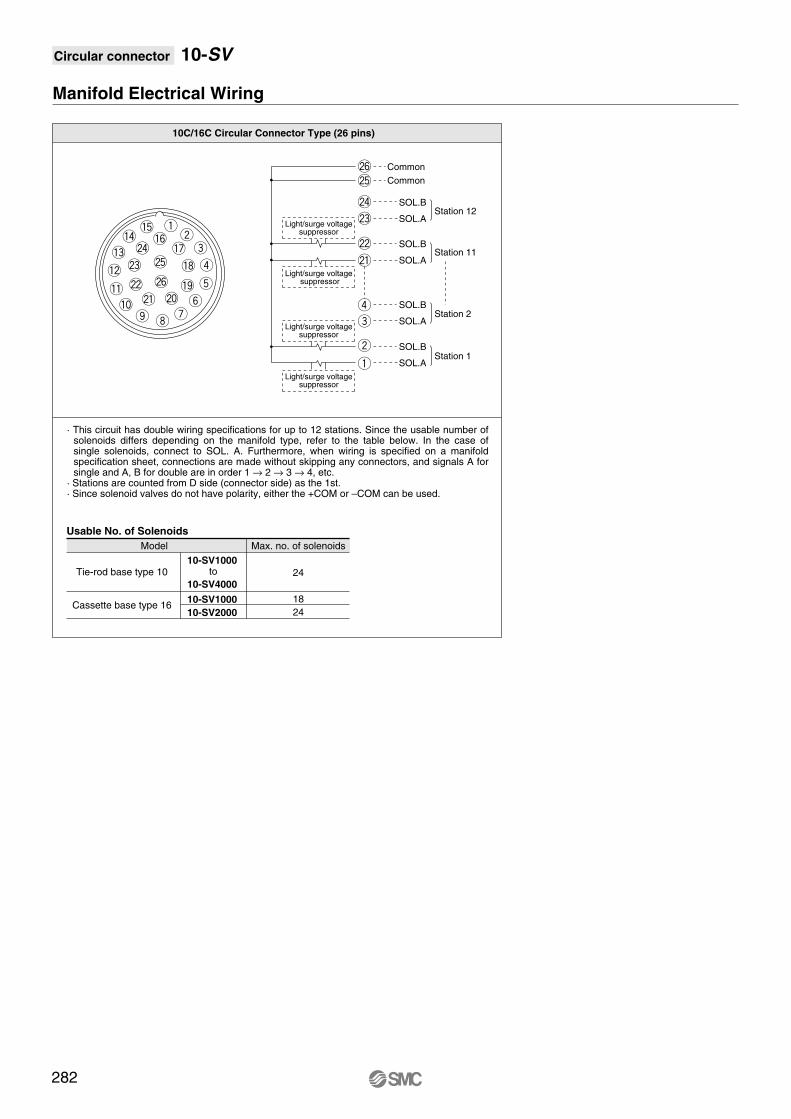
Circular connector 10-SV
10C/16C Circular Connector Type (26 pins)
Model Max. no. of solenoids
Tie-rod base type 1010-SV1000
10-SV400024
18
24
10-SV1000
10-SV2000Cassette base type 16
Manifold Electrical Wiring
q!5!4@4!3
!2 @3
@2!1!0
o i
@1
@6
@6@5
@4
@3
@2
@1
r
e
w
q
@5
!6!7w
e
r!8
!9y
t@0u
Light/surge voltagesuppressor
Common
Common
SOL.B
SOL.A
SOL.B
SOL.A
SOL.B
SOL.A
SOL.BStation 1
Station 2
Station 11
Station 12
SOL.A
Light/surge voltage suppressor
Light/surge voltagesuppressor
Light/surge voltagesuppressor
Usable No. of Solenoids
to
282
· This circuit has double wiring specifications for up to 12 stations. Since the usable number of solenoids differs depending on the manifold type, refer to the table below. In the case of single solenoids, connect to SOL. A. Furthermore, when wiring is specified on a manifold specification sheet, connections are made without skipping any connectors, and signals A for single and A, B for double are in order 1 → 2 → 3 → 4, etc.
· Stations are counted from D side (connector side) as the 1st.· Since solenoid valves do not have polarity, either the +COM or –COM can be used.

Air c
ylin
der
Rota
ry a
ctu
ato
rA
ir g
ripper
Directional contr
ol
valv
eF
ittings &
Tubin
gP
ressure
sw
itch
Cle
an g
as filt
er
Flo
w c
ontr
ol
equip
ment
Filt
er,
Pre
ssure
contr
ol equip
ment
Air p
repara
tion
equip
ment
Circular connector 10-SV
Dimensions: Series 10-SV1000 for circular connector
UDB
C3, N1C4, N3C6, N7
(R) -Stations• Cassette base manifold: 10-SS5V1-W16CD-
· When P, E port outlets are indicated on the U side or D side, the P, E ports on the opposite side are plugged.
· External pilot port positions are the same as P, E port outlet positions.
L1
L2
L3
L4
Ln 2
148
137.5
119.3
14.5
5
185.5
175
150.8
17.5
6
185.5
175
161.3
12
7
198
187.5
171.8
13
8
210.5
200
182.3
14
9
223
212.5
192.8
15
10
235.5
225
203.3
16
11
248
237.5
213.8
17
12
248
237.5
224.3
12
13
260.5
250
234.8
13
14
273
262.5
245.3
14
15
285.5
275
255.8
15
16
298
287.5
266.3
16
17
310.5
300
276.8
17
18
310.5
300
287.3
11.5
4
173
162.5
140.3
16.5
3
160.5
150
129.8
15.5
L Dimension n: Stations
A
B
A
B
A
B
A
B
A
B
(Pitch)
AB
AB
Notch
(To align connector position)DIN rail holding screw
(Station n) (Station 1)
(Rail mounting hole pitch: 12.5)
One-touch fitting
[1(P), 3/5(E) port]Applicable tubing O.D.: ø8
ø5/16"
P1
5 3 E
B
A
2
4
B
A
2
4
B
A
2
4
B
A
2
4
B
A
2
4
U side D side
P1
5 3 E
P1
5 3 E
B
A
2
4
B
A
2
4
B
A
2
4
B
A
2
4
B
A
2
4
One-touch fitting
[X: External pilot port]
Applicable tubing O.D.: ø4ø5/32"
One-touch fitting
[PE: Pilot EXH port]
Applicable tubing O.D.: ø4ø5/32"
With external pilot specifications
One-touch fitting
[4(A), 2(B) port]Applicable tubing O.D.: ø3.2, ø1/8"
ø4,ø5/32"ø6,ø1/4"
(When circular connector is mounted)
Light/surge voltage suppressor (Cable assembly)
Min. bending radius 20 mm
Block separation lever
P1
5 3 E
PE
X
PE
X
12
3
4 5
6
78
91
0
11
121
3
14
15 1
61
7
18
19
20
21
22
23
24
25 26
22.3 P=10.5
(4.9
)
(C6
:3.2
)(N
7:7
)
19
.7
48
10
23
63
12
.6
28
.6
13.5
8
37.3
45
.5
59
42
.31
6.6
58
.43
6.9
5.5
18
28
.8
83
.7
92
.2
45
.6
18.1 8.4
L3
L1
L2 5
35
(L4)
(81)
7.5
37.2
59.6
Manual override
Press and turn forthe locking type.( )
4(A) port side: Orange2(B) port side: Green
78
41
4
2
A
B
4
2
A
B
4
2
A
B
4
2
A
B
E3/5
1 P
Individual SUP spacer
Individual EXH spacer
E3/5
1 P
E 3 P 1 E 3 P 1
With option
283

Circular connector 10-SV
Dimensions: Series 10-SV2000 for circular connector
• Cassette base manifold: 10-SS5V2-W16CD-
L1
L2
L3
L4
Ln 2
160.5
150
135.3
12.5
5
210.5
200
183.3
13.5
6
223
212.5
199.3
12
7
248
237.5
215.3
16.5
8
260.5
250
231.3
14.5
9
273
262.5
247.3
13
10
298
287.5
263.3
17.5
11
310.5
300
279.3
15.5
12
323
312.5
295.3
14
13
335.5
325
311.3
12
14
360.5
350
327.3
16.5
15
373
362.5
343.3
15
16
385.5
375
359.3
13
17
410.5
400
375.3
17.5
18
423
412.5
391.3
16
19
435.5
425
407.3
14
20
448
437.5
423.3
12.5
4
198
187.5
167.3
15.5
3
185.5
175
151.3
17
L Dimension n: Stations
· When P, E port outlets are indicated on the U side or D side, the P, E ports on the opposite side are plugged.
· External pilot port positions are the same as P, E port outlet positions.
284
(Rail mounting hole pitch: 12.5)
One-touch fitting
[1(P), 3/5(E) port]Applicable tubing O.D.: ø10
ø3/8"
One-touch fitting
[4(A), 2(B) port]Applicable tubing O.D.: ø4, ø5/32"
ø6,ø1/4"ø8,ø5/16"
(Pitch)
DIN rail holding screw
With external pilot specifications
U side D side
One-touch fitting
[PE: Pilot EXH port]Applicable tubing O.D.: ø4
ø5/32"
One-touch fitting
[X: External pilot port]Applicable tubing O.D.: ø4
ø5/32"
Notch
(To align connector position)
5.5
27
.3
39
.5
35
10
2.9
11
5.5
23.5
12
.5
15
.9
31
.5
34
.6
P=1617.5
L2
L1
5
42
.3
16
.6
69
.1
53
.9
67
.5
8
56
.3
(5.3
)
18.8 9.5
43
.1
37.2
37.3
L3 (L4)
60.8(4
.9)
44
.5
Manual override
Press and turn for the locking type. ( )
4(A) port side: Orange2(B) port side: Green
86.5
50.5
Individual SUP spacer
Individual EXH spacer
With option
(Station n) (Station 1)
(When circular connector is mounted)
(DIN
ra
il d
ime
nsio
n)
Light/surge voltage suppressor (Cable assembly)
Min. bending radius 20 mm
Block separation lever
19
.7
56
.571
.5
7.5
(81)
UDB
C4, N3C6, N7C8, N9
(R) -Stations

Air c
ylin
der
Rota
ry a
ctu
ato
rA
ir g
ripper
Directional contr
ol
valv
eF
ittings &
Tubin
gP
ressure
sw
itch
Cle
an g
as filt
er
Flo
w c
ontr
ol
equip
ment
Filt
er,
Pre
ssure
contr
ol equip
ment
Air p
repara
tion
equip
ment
Circular connector 10-SV
Dimensions: Series 10-SV1000 for circular connector
• Tie-rod base manifold: 10-SS5V1-W10CD- (-D)UDB
C3, N1C4, N3C6, N7
(R) -Stations
· When P, E port outlets are indicated on the U side or D side, the P, E ports on the opposite side are plugged.
· External pilot port positions are the same as P, E port outlet positions.
L1
L2
L3
L4
L5
Ln 2
148
137.5
116.3
16
63
5
173
162.5
147.8
12.5
94.5
6
185.5
175
158.3
13.5
105
7
198
187.5
168.8
14.5
115.5
8
210.5
200
179.3
15.5
126
9
223
212.5
189.8
16.5
136.5
10
235.5
225
200.3
17.5
147
11
235.5
225
210.8
12.5
157.5
12
248
237.5
221.3
13.5
168
13
260.5
250
231.8
14.5
178.5
14
273
262.5
242.3
15.5
189
15
285.5
275
252.8
16.5
199.5
16
298
287.5
263.3
17.5
210
17
298
287.5
273.8
12
220.5
18
310.5
300
284.3
13
231
19
323
312.5
294.8
14
241.5
20
335.5
325
305.3
15
252
4
160.5
150
137.3
11.5
84
3
160.5
150
126.8
17
73.5
L Dimension n: Stations
A
B
A
B
A
B
A
B
A
B
AB
AB
B 2
A 4
B 2 B 2 B 2 B 2
A 4 A 4 A 4 A 4
DIN rail holding screw
(For DIN rail mounting)
(Station n) (Station 1)
(Rail mounting hole pitch: 12.5)
(Pitch)
One-touch fitting
[1(P), 3/5(E) port]Applicable tubing O.D.: ø10
ø5/16"
One-touch fitting
[4(A), 2(B) port]Applicable tubing O.D.: ø3.2, ø1/8"
ø4,ø5/32"ø6,ø1/4"
Notch(To align connector position)
1 P
3/5 E 3/5
1 P
E
12
3
4 5
6
78
9
10
11
121
3
14
15 1
61
7
18
19
20
21
22
23
24
25 26
E
1 P
35
B 2
A 4
B 2 B 2 B 2 B 2
A 4 A 4 A 4 A 4
1 P
5 3 E
One-touch fitting
[PE: Pilot EXH port]
Applicable tubing O.D.: ø4ø5/32"
One-touch fitting
[X: External pilot port]
Applicable tubing O.D.: ø4ø5/32"
(Fo
r D
IN r
ail
mo
un
tin
g)
(When circular connector is mounted)
U side D side
4-ø4.3
(For mounting)
(Cable assembly)
Min. bending radius 20 mm
Light/surge voltage suppressor
PE
X
PE
X
With external pilot specifications
83
.7
92
.2
Manual override
18.3
10
45
.51
0
23
59
.5
13.5P=10.5
8.6
24
.6
L5
38
.4
27.5
(81)
L3
L2
L1
5.5
(7.5
)
60.6
(4.9
)
(C6
:3.2
)(N
7:7
)
35
43
56
.5
11
.88
34
.6
8
(L4)
29
.61
0.8
39
.6
58
.9
47.89
2.6
14.1 8.4
5
8.9
Press and turn for the locking type. ( )
4(A) port side: Orange2(B) port side: Green
37.5
74.5
4A
2B
4A
2B
4A
2B
4A
2B
Individual SUP spacer
Individual EXH spacer
E
P1
3/5E3/5
P1
P 1E 3 P 1E 3
With option
285

Circular connector 10-SV
(-D)UDB
C4, N3C6, N7C8, N9
(R) -Stations
Dimensions: Series 10-SV2000 for circular connector
• Tie-rod base manifold: 10-SS5V2-W10CD-
· When P, E port outlets are indicated on the U side or D side, the P, E ports on the opposite side are plugged.
· External pilot port positions are the same as P, E port outlet positions.
L1
L2
L3
L4
L5
Ln 2
160.5
150
132.2
14
80
5
210.5
200
180.2
15
128
6
223
212.5
196.2
13.5
144
7
235.5
225
212.2
11.5
160
8
260.5
250
228.2
16
176
9
273
262.5
244.2
14.5
192
10
285.5
275
260.2
12.5
208
11
310.5
300
276.2
17
224
12
323
312.5
292.2
15.5
240
13
335.5
325
308.2
13.5
256
14
348
337.5
324.2
12
272
15
373
362.5
340.2
16.5
288
16
385.5
375
356.2
14.5
304
17
398
387.5
372.2
13
320
18
423
412.5
388.2
17.5
336
19
435.5
425
404.2
15.5
352
20
448
437.5
420.2
14
368
4
198
187.5
164.2
17
112
3
173
162.5
148.2
12.5
96
L Dimension n: Stations
286
Manual override
Press and turn forthe locking type. ( )
4(A) port side: Orange2(B) port side: Green
(Station n) (Station 1)
DIN rail holding screw
(For DIN rail mounting)
(Rail mounting hole pitch: 12.5)
(Pitch)
One-touch fitting
[1(P), 3/5(E) port]
Applicable tubing O.D.: ø10ø3/8"
One-touch fitting
[4(A), 2(B) port]Applicable tubing O.D.: ø4, ø5/32"
ø6, ø1/4"ø8, ø5/16"
4-ø5.3
(For mounting)
U side D side
(Fo
r D
IN r
ail
mo
un
tin
g)
(When circular connector is mounted)
Notch(To align connector position)
One-touch fitting
[PE: Pilot EXH port]Applicable tubing O.D.: ø4
ø5/32"
One-touch fitting
[X: External pilot port]Applicable tubing O.D.: ø4
ø5/32"
Light/surge voltage suppressor (Cable assembly)
Min. bending radius 20 mm
With external pilot specifications
12
52
.563
.5
11
5.5
(4.9
)
L5
20.5
9.2
25
.2
17.5P=16
11
.8
11
.9
30
.6
(7.5
)
29.5
40
.8
97
.55
.4
5.5
35
8
49
.9
63
.5
29
.61
2.2
11
.45
8.9 1
09
.4
(5.3
)
53
.4
10
2.9
15.8 9.5
46.2
L3 (L4)
L2 5
L1
(81)
60.7
With option
78.5 4
2.5
Individual EXH spacer
Individual SUP spacer

Air c
ylin
der
Rota
ry a
ctu
ato
rA
ir g
ripper
Directional contr
ol
valv
eF
ittings &
Tubin
gP
ressure
sw
itch
Cle
an g
as filt
er
Flo
w c
ontr
ol
equip
ment
Filt
er,
Pre
ssure
contr
ol equip
ment
Air p
repara
tion
equip
ment
Circular connector 10-SV
Dimensions: Series 10-SV3000 for circular connector
• Tie-rod base manifold: 10-SS5V3-W10CD-
· When P, E port outlets are indicated on the U side or D side, the P, E ports on the opposite side are plugged.
· External pilot port positions are the same as P, E port outlet positions.
L1
L2
L3
L4
L5
Ln 2
173
162.5
147.8
12.5
97
5
235.5
225
209.3
13
158.5
6
260.5
250
229.8
15.5
179
7
285.5
275
250.3
17.5
199.5
8
298
287.5
270.8
13.5
220
9
323
312.5
291.3
16
240.5
10
335.5
325
311.8
12
261
11
360.5
350
332.3
14
281.5
12
385.5
375
352.8
16.5
302
13
398
387.5
373.3
12.5
322.5
14
423
412.5
393.8
14.5
343
15
448
437.5
414.3
17
363.5
16
460.5
450
434.8
13
384
17
485.5
475
455.3
15
404.5
18
510.5
500
475.8
17.5
425
19
523
512.5
496.3
13.5
445.5
20
548
537.5
516.8
15.5
466
4
223
212.5
188.8
17
138
3
198
187.5
168.3
15
117.5
L Dimension n: Stations
287
Manual override
Press and turn forthe locking type. ( )
4(A) port side: Orange2(B) port side: Green
(Station n) (Station 1)
DIN rail holding screw
(For DIN rail mounting)
(Rail mounting hole pitch: 12.5)
(Pitch)
One-touch fitting
[1(P), 3/5(E) port]Applicable tubing O.D.: ø12
ø3/8"
4-ø5.3
(For mounting)
(Fo
r D
IN r
ail
mo
un
tin
g)
U side D side
(When circular connector is mounted)
One-touch fitting
[4(A), 2(B) port]Applicable tubing O.D.: ø 6,ø1/4"
ø 8,ø5/16"ø10,ø3/8"
One-touch fitting
[X: External pilot port]Applicable tubing O.D.: ø6
ø1/4"
One-touch fitting
[PE: Pilot EXH port]Applicable tubing O.D.: ø6
ø1/4"
Notch
(To align connector position)
Light/surge voltage suppressor (Cable assembly)
Min. bending radius 20 mm
With external pilot specifications
12
63
.882
.71
15
.8
12
8.8
L2
L1
5
21.3P=20.523.5
13
.5
36
.1
8
83
.85
(5.1
)
5.5
11
.6
37
.6
14
.7
(10
)
35
60
.3
76
.8
14
.32
9.646
.9
58
.91
0.1
(5.3
)
18 11
42.8
39
.6
(81)
L5 44.3
L3 (L4)
61.3
101.2
58.4
1
Individual EXH spacer
Individual SUP spacer 1 1
With option
1
(-D)UDB
C6, N7C8, N9C10, N11
(R) -Stations

Circular connector 10-SV
Dimensions: Series 10-SV4000 for circular connector
• Tie-rod base manifold: 10-SS5V4-W10CD-
· When P, E port outlets are indicated on the U side or D side, the P, E ports on the opposite side are plugged.
· External pilot port positions are the same as P, E port outlet positions.
L1
L2
L3
L4
L5
Ln 2
198
187.5
162.8
17.5
109
5
260.5
250
234.8
13
181
6
285.5
275
258.8
13.5
205
7
310.5
300
282.8
14
229
8
335.5
325
306.8
14.5
253
9
360.5
350
330.8
15
277
10
385.5
375
354.8
15.5
301
11
410.5
400
378.8
16
325
12
435.5
425
402.8
16.5
349
13
460.5
450
426.8
17
373
14
485.5
475
450.8
17.5
397
15
498
487.5
474.8
11.5
421
16
523
512.5
498.8
12
445
17
548
537.5
522.8
12.5
469
18
573
562.5
546.8
13
493
19
598
587.5
570.8
13.5
517
20
623
612.5
594.8
14
541
4
235.5
225
210.8
12.5
157
3
210.5
200
186.8
12
133
L Dimension n: Stations
288
(Pitch)
U side D side
One-touch fitting
[1(P), 3/5(E) port]Applicable tubing O.D.: ø12
ø3/8"
One-touch fitting
[4(A), 2(B) port]Applicable tubing O.D.: ø8, ø5/16"
ø10,ø3/8"ø12
DIN rail holding screw
(For DIN rail mounting)
4-ø6.2
(For mounting)
(Rail mounting hole pitch: 12.5)
Light/surge voltage suppressor
(Station n) (Station 1)
(Fo
r D
IN r
ail
mo
un
tin
g)
(When circular connector is mounted)
(Cable assembly)
Min. bendingradius 20 mm
With external pilot specifications
Notch
(To align connector position)
One-touch fitting
[X: External pilot port]Applicable tubing O.D.: ø6
ø1/4"
One-touch fitting
[PE: Pilot EXH port]Applicable tubing O.D.: ø6
ø1/4"[R
c 1
/4,
3/8
]
1/4,3/8
[4(A), 2(B) port]
3/8
[1(P), 3(E) port]
24P=24
14
.5
35
(5.4
)
L5
8
17
.52
9.6
56
.3
98
.2
14
8.2
16
4.7
81
.7
58
.9
12
.2
75
16
.2
61
.885
.51
4.7
5
65.8
13
.7
35
.8
L2
L1
47.3
L3 (L4)5
.5
35
(10
)
(84.5)
33.84
1.6
11
58
.3
74
.8
2025
13
.3
Manual override
Press and turn for the locking type. ( )4(A) port side: Orange2(B) port side: Green
With option
105.5
58.5
Individual EXH spacer
Individual SUP spacer
02,03,
C8, C10,C12,
N9N11 (-D)
UDB
(R) -Stations

Air c
ylin
der
Rota
ry a
ctu
ato
rA
ir g
ripper
Directional contr
ol
valv
eF
ittings &
Tubin
gP
ressure
sw
itch
Cle
an g
as filt
er
Flo
w c
ontr
ol
equip
ment
Filt
er,
Pre
ssure
contr
ol equip
ment
Air p
repara
tion
equip
ment
D-sub connector
Applicable
series
Cassette base manifold
10-SV1000/10-SV2000
Tie-rod base manifold
10-SV1000/10-SV2000/10-SV3000/10-SV4000
· Number of connectors: 25 pins
· MIL-C-24308
Conforming to JIS-X-5101
Tie-rod base
Cassette base
289

— — —
— — —Tie-rod base
Cassette base
Series
—1 1
1
2
10-SV1000
10-SV2000
— 0516FD1 1
Valve stations
DIN rail length specified
Standard length
Specify a longer rail
than the standard length.
Nil
3
20 Note)
Note
Double wiring
specifications Note 1)
Specified layout Note 2)
(Up to 23 solenoids possible)
Symbol
02
11
02
20
Stations
2 stations
11 stations
2 stations
20 stations
Connector entry direction
1
2
Upward
Lateral
Series
1
2
3
4
10-SV1000
10-SV2000
10-SV3000
10-SV4000
P, E port location
U
D
B
U side (2 to 10 stations)
D side (2 to 10 stations)
Both sides (2 to 20 stations)
···
···
···
···
For 3 stations
For 20 stations
···
···
MountingDirect mounting
DIN rail mounting (With DIN rail)
DIN rail mounting (Without DIN rail)
Nil
D
D0Note)
D3
D20
For 3 stations
For 20 stations
···
···
Pilot type
Internal pilot
External pilot
Nil
R
Note) In case of D0, only DIN rail fittings are attached.
Valve stations
10-SV1000 Series
Series 10-SV2000
Note
Double wiring
specifications Note 1)
Specified layout Note 2)
(Up to 18 solenoids possible)
Symbol
02
09
02
18
Stations
2 stations
9 stations
2 stations
18 stations
···
···
···
···
Note
Double wiring
specifications Note 1)
Specified layout Note 2)
(Up to 23 solenoids possible)
Symbol
02
11
02
20
Stations
2 stations
11 stations
2 stations
20 stations
···
···
···
···
05 U10FD
U
A, B port size (Inch)A, B port size (Metric)
Symbol
N1
N3
N7
N3
N7
N9
N7
N9
N11
N9
N11
02N
03N
02T
03T
M
One-touch fitting for ø1/8"
One-touch fitting for ø5/32"
One-touch fitting for ø1/4"
One-touch fitting for ø5/32"
One-touch fitting for ø1/4"
One-touch fitting for ø5/16"
One-touch fitting for ø1/4"
One-touch fitting for ø5/16"
One-touch fitting for ø3/8"
One-touch fitting for ø5/16"
One-touch fitting for ø3/8"
NPT 1/4
NPT 3/8
NPTF 1/4
NPTF 3/8
A, B ports mixed
One-touch
fitting for ø5/16"
P, E port Applicable series
10-SV1000
10-SV2000
10-SV3000
10-SV4000
One-touch
fitting for ø3/8"
One-touch
fitting for ø3/8"
One-touch
fitting for ø3/8"
NPT3/8
NPTF3/8
A, B portA, B portSymbol
C3
C4
C6
C4
C6
C8
C6
C8
C10
C8
C10
C12
02
03
02F
03F
M
One-touch fitting for ø3.2
One-touch fitting for ø4
One-touch fitting for ø6
One-touch fitting for ø4
One-touch fitting for ø6
One-touch fitting for ø8
One-touch fitting for ø6
One-touch fitting for ø8
One-touch fitting for ø10
One-touch fitting for ø8
One-touch fitting for ø10
One-touch fitting for ø12
Rc 1/4
Rc 3/8
G 1/4
G 3/8
A, B ports mixed
One-touch
fitting for ø8
P, E port Applicable series
10-SV1000
10-SV2000
10-SV3000
10-SV4000
One-touch
fitting for ø10
One-touch
fitting for ø12
One-touch
fitting for ø12
Rc3/8
G3/8
Double wiring specifications: Single, double, 3 position and 4 position solenoid valves can be used at all of the manifold stations.Use of a single solenoid will result in an unused control signal in an unused control signal. If this is not desired, order with a specified layout. Specified layout: Indicate wiring specifications on the manifold specification sheet. (Note that double, 3 and 4 position valves cannot be used where single solenoid wiring
Double wiring specifications: Single, double, 3 position and 4 position solenoid valves can be used at all of the manifold stations.Use of a single solenoid will result in an unused control signal. If this is not desired, order with a specified layout.Specified layout: Indicate wiring specifications on the manifold specification sheet. (Note that double, 3 and 4 position valves cannot be used where single solenoid wiring has been specified.)
Note) Able to specify the length for 3 stations up to 18 stations for 10-SV1000, which is available with 18 stations at the maximum.
∗ In the case of mixed specifications (M), indicate separately on the manifold specification sheet. ∗ Port sizes of X, PE port for external pilot specification (R) are ø4 (metric), ø5/32" (inch) for 10-SV1000/2000 and ø6 (metric) and ø1/4" (inch) for 10-SV3000/4000.
SS5V
SS5VClean series
—
—
10
10
Series 10-SV D-sub connector
How to Order
290
Note 1)
Note 2)
Note 1)
Note 2)
When a longer DIN rail is desired than the specified stations. (Specify a longer rail than the standard length.)
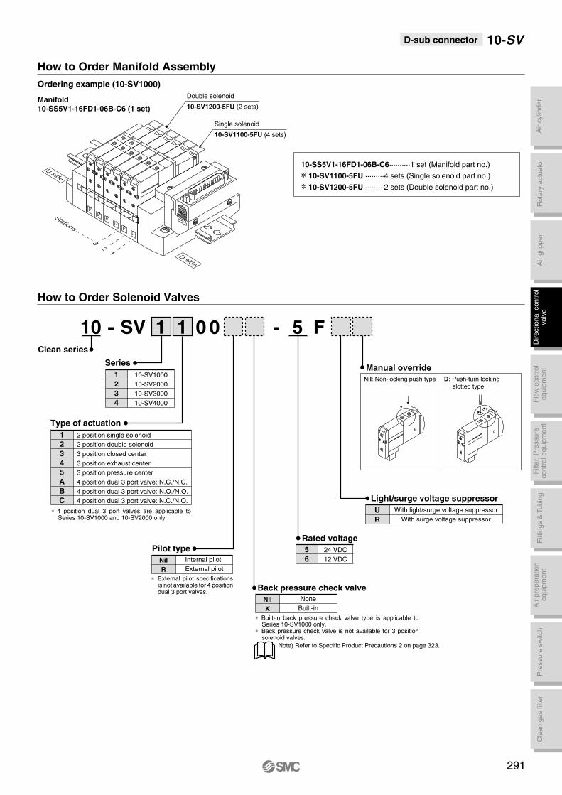
Air c
ylin
der
Rota
ry a
ctu
ato
rA
ir g
ripper
Directional contr
ol
valv
eF
ittings &
Tubin
gP
ressure
sw
itch
Cle
an g
as filt
er
Flo
w c
ontr
ol
equip
ment
Filt
er,
Pre
ssure
contr
ol equip
ment
Air p
repara
tion
equip
ment
D-sub connector 10-SV
How to Order Manifold Assembly
Ordering example (10-SV1000)
Manual override
Rated voltage
Nil: Non-locking push type D: Push-turn locking
slotted type
-1 1 0 0 F5
5
6
24 VDC
12 VDC
Light/surge voltage suppressor
With light/surge voltage suppressor
With surge voltage suppressor
U
R
Pilot type
∗ External pilot specifications is not available for 4 position dual 3 port valves.
∗ 4 position dual 3 port valves are applicable to Series 10-SV1000 and 10-SV2000 only.
∗ Built-in back pressure check valve type is applicable to Series 10-SV1000 only.
∗ Back pressure check valve is not available for 3 position solenoid valves.
How to Order Solenoid Valves
Internal pilot
External pilot
Nil
R
Back pressure check valve
None
Built-in
Nil
K
Series
1
2
3
4
10-SV1000
10-SV2000
10-SV3000
10-SV4000
Type of actuation
1
2
3
4
5
A
B
C
2 position single solenoid
2 position double solenoid
3 position closed center
3 position exhaust center
3 position pressure center
4 position dual 3 port valve: N.C./N.C.
4 position dual 3 port valve: N.O./N.O.
4 position dual 3 port valve: N.C./N.O.
Double solenoid
10-SV1200-5FU (2 sets)
Single solenoid
10-SV1100-5FU (4 sets)
32
1
Stations
U side
D side
10-SS5V1-16FD1-06B-C6··········1 set (Manifold part no.)
10-SV1100-5FU··········4 sets (Single solenoid part no.)
10-SV1200-5FU··········2 sets (Double solenoid part no.)
Manifold10-SS5V1-16FD1-06B-C6 (1 set)
DD
DD
DD
Note) Refer to Specific Product Precautions 2 on page 323.
SVClean series
-10
291
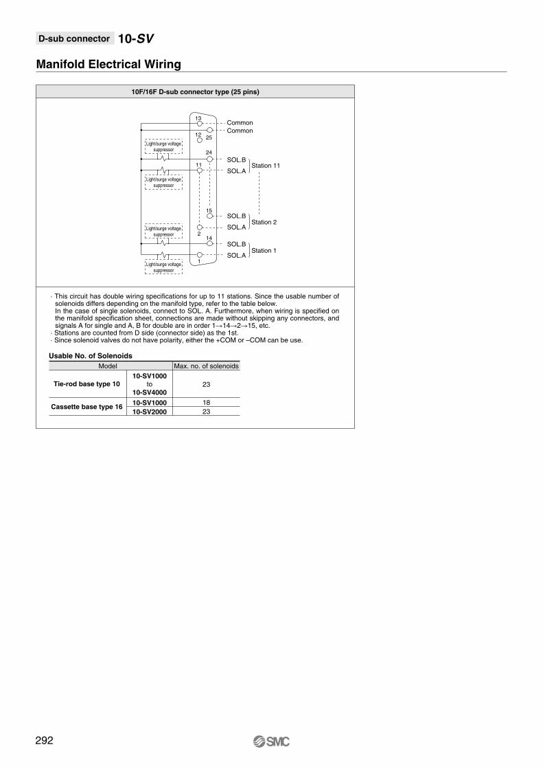
D-sub connector 10-SV
10F/16F D-sub connector type (25 pins)
Model Max. no. of solenoids
Tie-rod base type 1010-SV1000
10-SV400023
18
23
10-SV1000
10-SV2000Cassette base type 16
Manifold Electrical Wiring
Usable No. of Solenoids
to
Light/surge voltagesuppressor
Light/surge voltagesuppressor
Light/surge voltagesuppressor
Light/surge voltagesuppressor
Common
Common
SOL.B
SOL.A
SOL.B
SOL.A
SOL.BStation 1
Station 2
Station 11
SOL.A
13
12
11
2
1
25
24
15
14
292
· This circuit has double wiring specifications for up to 11 stations. Since the usable number of solenoids differs depending on the manifold type, refer to the table below. In the case of single solenoids, connect to SOL. A. Furthermore, when wiring is specified on the manifold specification sheet, connections are made without skipping any connectors, and signals A for single and A, B for double are in order 114215, etc.
· Stations are counted from D side (connector side) as the 1st.· Since solenoid valves do not have polarity, either the +COM or –COM can be use.

Air c
ylin
der
Rota
ry a
ctu
ato
rA
ir g
ripper
Directional contr
ol
valv
eF
ittings &
Tubin
gP
ressure
sw
itch
Cle
an g
as filt
er
Flo
w c
ontr
ol
equip
ment
Filt
er,
Pre
ssure
contr
ol equip
ment
Air p
repara
tion
equip
ment
D-sub connector 10-SV
UDB
12
C3, N1C4, N3C6, N7
Dimensions: Series 10-SV1000 for D-sub Connector
• Cassette base manifold: 10-SS5V1-16FD (R)--
· When P, E port outlets are indicated on the U side or D side, the P, E ports on the opposite side are plugged.
· External pilot port positions are the same as P, E port outlet positions.
L1
L2
L3
L4
Ln 2
123
112.5
93.5
18
5
160.5
150
125
21
6
173
162.5
135.5
22
7
185.5
175
146
23
8
198
187.5
156.5
24
9
198
187.5
167
18.5
10
210.5
200
177.5
19.5
11
223
212.5
188
20.5
12
235.5
225
198.5
21.5
13
248
237.5
209
22.5
14
260.5
250
219.5
23.5
15
260.5
250
230
18.5
16
273
262.5
240.5
19.5
17
285.5
275
251
20.5
18
298
287.5
261.5
21.5
4
148
137.5
114.5
20
3
135.5
125
104
19
L Dimension n: Stations
(Pitch)
(Rail mounting hole pitch: 12.5)
(Lateral connector entry)
DIN rail holding screw
(Station n) (Station 1)
One-touch fitting
[1(P), 3/5(E) port]Applicable tubing O.D.: ø8
ø5/16"One-touch fitting
[4(A), 2(B) port]Applicable tubing O.D.: ø3.2, ø1/8"
ø4, ø5/32"ø6, ø1/4"
JIS-X-5101MIL-C-24308
Equivalent to applicable D-sub connector
U side D side
P1
5 3 E
P1
5 3 E
B
A
2
4
B
A
2
4
B
A
2
4
B
A
2
4
B
A
2
4
One-touch fitting
[X: External pilot port]Applicable tubing O.D.: ø4
ø5/32"
One-touch fitting
[PE: Pilot EXH port]Applicable tubing O.D.: ø4
ø5/32"
Connector case
Release lever (Both sides)
2-M2.6
2-4-40 UNC[4(A), 2(B) with inch size ports]
Light/surge voltage suppressor
Block separation lever
With external pilot specifications
B
A
2
4
B
A
2
4
B
A
2
4
B
A
2
4
B
A
2
4
A
B
A
B
A
B
A
B
AB
A
B
AB
P1
5 3 E
P1
5 3 E
PE
X
PE
X
P=10.5
(4.9
)
28
.8
(C6
:3.2
)(N
7:7
)
83
.7
92
.2 18
19
.7
48
10
23
63
7.5
12
.6
28
.6
13.5
35
42
.31
6.6
36
.95
8.4
8
7.9
L3 (L4)
L2 5
L1
5.5
22.3 33.8
61
.2
45
.5
59
18.1 8.4
(47
.3)
(6)
Manual override
Press and turn for the locking type. ( )
4(A) port side: Orange2(B) port side: Green
78
41
4
2
A
B
4
2
A
B
4
2
A
B
4
2
A
B
E3/5
1 P
Individual SUP spacer
Individual EXH spacer
E3/5
1 P
E 3 P 1
With option
E 3 P 1
293
Stations
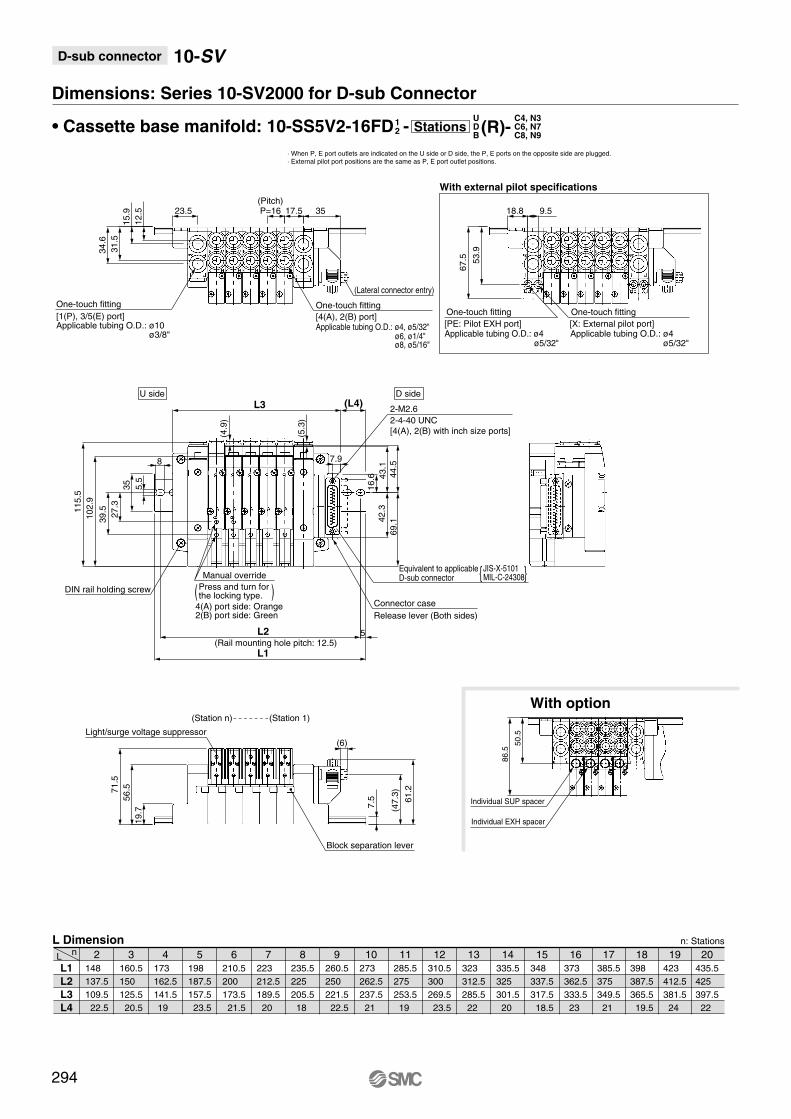
D-sub connector 10-SV
UDB
12
Dimensions: Series 10-SV2000 for D-sub Connector
• Cassette base manifold: 10-SS5V2-16FD - (R)-
L1
L2
L3
L4
Ln 2
148
137.5
109.5
22.5
5
198
187.5
157.5
23.5
6
210.5
200
173.5
21.5
7
223
212.5
189.5
20
8
235.5
225
205.5
18
9
260.5
250
221.5
22.5
10
273
262.5
237.5
21
11
285.5
275
253.5
19
12
310.5
300
269.5
23.5
13
323
312.5
285.5
22
14
335.5
325
301.5
20
15
348
337.5
317.5
18.5
16
373
362.5
333.5
23
17
385.5
375
349.5
21
18
398
387.5
365.5
19.5
19
423
412.5
381.5
24
20
435.5
425
397.5
22
4
173
162.5
141.5
19
3
160.5
150
125.5
20.5
L Dimension n: Stations
· When P, E port outlets are indicated on the U side or D side, the P, E ports on the opposite side are plugged.
· External pilot port positions are the same as P, E port outlet positions.
C4, N3C6, N7C8, N9
294
Manual override
Press and turn for the locking type. ( )
4(A) port side: Orange2(B) port side: Green
(Station n) (Station 1)
(Rail mounting hole pitch: 12.5)
One-touch fitting
[1(P), 3/5(E) port]Applicable tubing O.D.: ø10
ø3/8"
One-touch fitting
[4(A), 2(B) port]Applicable tubing O.D.: ø4, ø5/32"
ø6, ø1/4"ø8, ø5/16"
(Pitch)
DIN rail holding screw
With external pilot specifications
U side D side
JIS-X-5101MIL-C-24308
Equivalent to applicable D-sub connector
(Lateral connector entry)
One-touch fitting
[PE: Pilot EXH port]Applicable tubing O.D.: ø4
ø5/32"
One-touch fitting
[X: External pilot port]Applicable tubing O.D.: ø4
ø5/32"
Connector case
Release lever (Both sides)
2-M2.6
2-4-40 UNC
[4(A), 2(B) with inch size ports]
Light/surge voltage suppressor
Block separation lever
19
.7
56
.571
.5
7.5
27
.3
39
.5
10
2.9
11
5.5
43
.1
69
.1
23.5
12
.5
15
.9
31
.5
34
.6
P=16 17.5
61
.2
L2
L1
5
5.5
35
8
L3 (L4)
42
.3
16
.6
35
53
.9
67
.57.9
(5.3
)
18.8 9.5
(47
.3)
(6)
(4.9
)
44
.5
86.5
50.5
Individual SUP spacer
Individual EXH spacer
With option
Stations

Air c
ylin
der
Rota
ry a
ctu
ato
rA
ir g
ripper
Directional contr
ol
valv
eF
ittings &
Tubin
gP
ressure
sw
itch
Cle
an g
as filt
er
Flo
w c
ontr
ol
equip
ment
Filt
er,
Pre
ssure
contr
ol equip
ment
Air p
repara
tion
equip
ment
D-sub connector 10-SV
UDB
12
C3, N1C4, N3C6, N7
Dimensions: Series 10-SV1000 for D-sub Connector
• Tie-rod base manifold: 10-SS5V1-10FD (R)--
· When P, E port outlets are indicated on the U side or D side, the P, E ports on the opposite side are plugged.
· External pilot port positions are the same as P, E port outlet positions.
L1
L2
L3
L4
L5
Ln 2
123
112.5
90.5
19.5
63
5
160.5
150
122
22.5
94.5
6
173
162.5
132.5
23.5
105
7
173
162.5
143
18
115.5
8
185.5
175
153.5
19
126
9
198
187.5
164
20
136.5
10
210.5
200
174.5
21
147
11
223
212.5
185
22
157.5
12
235.5
225
195.5
23
168
13
235.5
225
206
18
178.9
14
248
237.5
216.5
19
189
15
260.5
250
227
20
199.5
16
273
262.5
237.5
21
210
17
285.5
275
248
22
220.5
18
298
287.5
258.5
23
231
19
310.5
300
269
24
241.5
20
310.5
300
279.5
18.5
252
4
148
137.5
111.5
21.5
84
3
135.5
125
101
20.5
73.5
L Dimension n: Stations
(-D)
(Pitch)
(Lateral connector entry)
DIN rail holding screw
(For DIN rail mounting)
(Station n) (Station 1)
(Rail mounting hole pitch: 12.5)
JIS-X-5101MIL-C-24308
Equivalent to applicable D-sub connector
One-touch fitting
[1(P), 3/5(E) port]
Applicable tubing O.D.: ø8ø5/16"
A
B
A
B
A
B
A
B
AB
A
B
AB
B 2
A 4
One-touch fitting
[4(A), 2(B) port]Applicable tubing O.D.: ø3.2, ø1/8"
ø4, ø5/32"ø6, ø1/4"
(Fo
r D
IN r
ail
mo
un
tin
g)
B 2
A 4
B 2 B 2 B 2 B 2
A 4 A 4 A 4 A 4
1 P
3/5 E
One-touch fitting
[PE: Pilot EXH port]Applicable tubing O.D.: ø4
ø5/32"
One-touch fitting
[X: External pilot port]Applicable tubing O.D.: ø4
ø5/32"
3/5
1 P
E3/5
1 P
E
U side D side
4-ø4.3
(For mounting)
1 P
3/5 E
Connector case
Release lever (Both sides)
2-M2.6
2-4-40 UNC[4(A), 2(B) with inch size ports]
Light/surge voltage suppressor
B 2
A 4
B 2
A 4
B 2
A 4
B 2
A 4
PE
X
PE
X
With external pilot specifications
(7.5
)
18.3
10
45
.51
0
23
59
.5
51
.58
.6 24
.6
(4.9
)
(C6
:3.2
)(N
7:7
)
13.5P=10.5
L3
34.8 (6)
L5
(37
.6)
83
.71
1.8
43
56
.5
L2 5
L1
(L4)
355
.5
8
92
.2
83
4.6
29
.61
0.8
39
.6
22
8.9
58
.9 92
.6
7.9
14.1 8.4
Manual override
Press and turn for the locking type. ( )
4(A) port side: Orange2(B) port side: Green
37
.574.5
4A
2B
4A
2B
4A
2B
4A
2B
Individual SUP spacer
Individual EXH spacer
E
P1
3/5E3/5
P1
P 1E 3 P 1E 3
With option
295
Stations

D-sub connector 10-SV
UDB
12
C4, N3C6, N7C8, N9
Dimensions: Series 10-SV2000 for D-sub Connector
• Tie-rod base manifold: 10-SS5V2-10FD (R)--
· When P, E port outlets are indicated on the U side or D side, the P, E ports on the opposite side are plugged.
· External pilot port positions are the same as P, E port outlet positions.
L1
L2
L3
L4
L5
Ln 2
135.5
125
106.4
17.5
80
5
185.5
175
154.4
18.5
128
6
210.5
200
170.4
23
144
7
223
212.5
186.4
21.5
160
8
235.5
225
202.4
19.5
176
9
248
237.5
218.4
18
192
10
273
262.5
234.4
22.5
208
11
285.5
275
250.4
20.5
224
12
298
287.5
266.4
19
240
13
323
312.5
282.4
23.5
256
14
335.5
325
298.4
21.5
272
15
348
337.5
314.4
20
288
16
360.5
350
330.4
18
304
17
385.5
375
346.4
22.5
320
18
398
387.5
362.4
21
336
19
410.5
400
378.4
19
352
20
435.5
425
394.4
23.5
368
4
173
162.5
138.4
20.5
112
3
160.5
150
122.4
22
96
L Dimension n: Stations
(-D)
Manual override
Press and turn for the locking type. ( )
4(A) port side: Orange2(B) port side: Green
P1
E3/5 3/5
B
A
2
4
B
A
2
4
B
A
2
4
B
A
2
4
B
A
2
4
(Station n) (Station 1)
DIN rail holding screw
(For DIN rail mounting)
(Rail mounting hole pitch: 12.5)
(Pitch)
One-touch fitting
[1(P), 3/5(E) port]
Applicable tubing O.D.: ø10ø3/8"
One-touch fitting
[4(A), 2(B) port]Applicable tubing O.D.: ø4, ø5/32"
ø6, ø1/4"ø8, ø5/16"
A
B
AB
A
B
A
B
A
B
A
B
AB
1 P
E
(Lateral connector entry)
J-X-5101MIL-C-24308
P1
E3/5 3/5
B
A
2
4
B
A
2
4
B
A
2
4
B
A
2
4
B
A
2
4
1 P
E
One-touch fitting
[PE: Pilot EXH port]Applicable tubing O.D.: ø4
ø5/32"
One-touch fitting
[X: External pilot port]Applicable tubing O.D.: ø4
ø5/32"
(Fo
r D
IN r
ail
mo
un
tin
g)
U side D side
4-ø5.3
(For mounting)
Connector case
Release lever (Both sides)
2-M2.6
2-4-40 UNC[4(A), 2(B) with inch size ports]
Light/surge voltage suppressor
With external pilot specifications
PE
X
PE
X
12
52
.563
.5
(7.5
)
11
5.5
10
9.4
L5
20.5
9.2
25
.2
17.5P=16
53
.5
(L4)L3
L2
L1
5
(4.9
)
11
.9 30
.6
34.9
49
.9
63
.5
11
.8
29
.61
2.2
5.5
35
5.4
97
.5
8
58
.91
1.4
7.9
20.4
(5.3
)
53
.4
10
2.9
15.8 9.5
(39
.6)
(6)
With option
78.5 4
2.5
4
2
A
B
4
2
A
B
4
2
A
B
4
2
A
B
3/5 E
1 P
Individual EXH spacer
Individual SUP spacer
V
5
3 E
E
P1
3/5
V
1 P
V
5
3 E
V
1 P
296
Equivalent to applicable D-sub connector
Stations
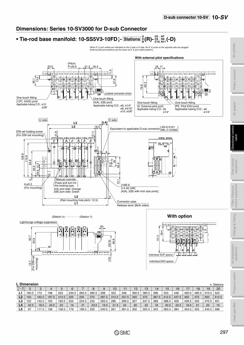
Air c
ylin
der
Rota
ry a
ctu
ato
rA
ir g
ripper
Directional contr
ol
valv
eF
ittings &
Tubin
gP
ressure
sw
itch
Cle
an g
as filt
er
Flo
w c
ontr
ol
equip
ment
Filt
er,
Pre
ssure
contr
ol equip
ment
Air p
repara
tion
equip
ment
D-sub connector 10-SV 10-SV
UDB
12
C6 , N7C8 , N9C10, N11
Dimensions: Series 10-SV3000 for D-sub Connector
• Tie-rod base manifold: 10-SS5V3-10FD (R)--
· When P, E port outlets are indicated on the U side or D side, the P, E ports on the opposite side are plugged.
· External pilot port positions are the same as P, E port outlet positions.
L1
L2
L3
L4
L5
Ln 2
160.5
150
122
22.5
97
5
223
212.5
183.5
23
158.5
6
235.5
225
204
19
179
7
260.5
250
224.5
21
199.5
8
285.5
275
245
23.5
220
9
298
287.5
265.5
19.5
240.5
10
323
312.5
286
21.5
261
11
348
337.5
306.5
24
281.5
12
360.5
350
327
20
302
13
385.5
375
347.5
22
322.5
14
398
387.5
368
18
343
15
423
412.5
388.5
20.5
363.5
16
448
437.5
409
22.5
384
17
460.5
450
429.5
18.5
404.5
18
485.5
475
450
21
425
19
510.5
500
470.5
23
445.5
20
523
512.5
491
19
466
4
198
187.5
163
20.5
138
3
173
162.5
142.5
18.5
117.5
L Dimension n: Stations
(-D)
297
Manual override
Press and turn for the locking type. ( )
4(A) port side: Orange2(B) port side: Green
(Station n) (Station 1)
DIN rail holding screw
(For DIN rail mounting)
(Rail mounting hole pitch: 12.5)
(Pitch)
One-touch fitting
[1(P), 3/5(E) port]Applicable tubing O.D.: ø12
ø3/8"
(Fo
r D
IN r
ail
mo
un
tin
g)
4-ø5.3
(For mounting)
(Lateral connector entry)
U side D side
JIS-X-5101MIL-C-24308Equivalent to applicable D-sub connector
One-touch fitting
[4(A), 2(B) port]Applicable tubing O.D.: ø6, ø1/4"
ø8, ø5/16"ø10, ø3/8"
One-touch fitting
[X: External pilot port]Applicable tubing O.D.: ø6
ø1/4"
One-touch fitting
[PE: Pilot EXH port]Applicable tubing O.D.: ø6
ø1/4"
Connector case
Release lever (Both sides)
2-M2.6
2-4-40 UNC[4(A), 2(B) with inch size ports]
Light/surge voltage suppressor
With external pilot specifications
12
63
.882
.7
11
5.8
12
8.8
L5
21.3P=20.523.5
13
.5
36
.1
11
.6
37
.6
83
.85
35.5
L3
(5.1
)
8
66
.8
(10
)
35
5.5
L2
L1
5
(L4)
14
.7
60
.3
76
.8
14
.32
9.64
6.9
18.5
7.9
58
.91
0.1
(5.3
)
18 11
(52
.9)
(6)
101.2
58.4
1
Individual EXH spacer
Individual SUP spacer 1 1
With option
1
Stations

D-sub connector 10-SV
UDB
12
Dimensions: Series 10-SV4000 for D-sub Connector
• Tie-rod base manifold: 10-SS5V4-10FD (R)--
· When P, E port outlets are indicated on the U side or D side, the P, E ports on the opposite side are plugged.
· External pilot port positions are the same as P, E port outlet positions.
L1
L2
L3
L4
L5
Ln 2
173
162.5
137
21
109
5
248
237.5
209
22.5
181
6
273
262.5
233
23
205
7
298
287.5
257
23.5
229
8
310.5
300
281
18
253
9
335.5
325
305
18.5
277
10
360.5
350
329
19
301
11
385.5
375
353
19.5
325
12
410.5
400
377
20
349
13
435.5
425
401
20.5
373
14
460.5
450
425
21
397
15
485.5
475
449
21.5
421
16
510.5
500
473
22
445
17
535.5
525
497
22.5
469
18
560.5
550
521
23
493
19
585.5
575
545
23.5
517
20
610.5
600
569
24
541
4
223
212.5
185
22
157
3
198
187.5
161
21.5
133
L Dimension n: Stations
02,03,
N9N11
C8,C10,C12,
(-D)Stations
298
Manual override
Press and turn for the locking type. ( )4(A) port side: Orange2(B) port side: Green
(Pitch)
U side D side
(Lateral connector entry)
One-touch fitting
[X: External pilot port]Applicable tubing O.D.: ø6
ø1/4"
One-touch fitting
[PE: Pilot EXH port]Applicable tubing O.D.: ø6
ø1/4"
One-touch fitting
[1(P), 3/5(E) port]Applicable tubing O.D.: ø12
ø3/8"One-touch fitting
[4(A), 2(B) port]Applicable tubing O.D.: ø8, ø5/16"
ø10, ø3/8"ø12
Light/surge voltage suppressor
(Station n) (Station 1)
DIN rail holding screw
(For DIN rail mounting)
(Rail mounting hole pitch: 12.5)
4-ø6.2
(For mounting)
Connector case
Release lever (Both sides)
2-M2.6
2-4-40 UNC[4(A), 2(B) with inch size ports]
JIS-X-5101MIL-C-24308
Equivalent to applicable D-sub connector
(Fo
r D
IN r
ail
mo
un
tin
g)
[Rc 1
/4,
3/8
]
1/4,3/8
[4(A), 2(B) port]
3/8
[1(P), 3(E) port]
With external pilot specifications
14
.5
35
4024P=24
61
.885
.5
57
.8
11
58
.3
74
.8
25 (6)
(43
.9)
16
.2
(10
)
29
.61
7.5
56
.3
98
.2
14
8.2
16
4.7
5.5
35
12
.25
8.9
81
.77
5
87.9
13
.7
35
.8
20
L2
L1
5
(5.4
)
L5 21.5
L3 (L4)
14
.7
13
.3
With option
105.5
58.5
Individual EXH spacer
Individual SUP spacer

Air c
ylin
der
Rota
ry a
ctu
ato
rA
ir g
ripper
Directional contr
ol
valv
eF
ittings &
Tubin
gP
ressure
sw
itch
Cle
an g
as filt
er
Flo
w c
ontr
ol
equip
ment
Filt
er,
Pre
ssure
contr
ol equip
ment
Air p
repara
tion
equip
ment
Flat Ribbon Cable Connector
Applicable
series
Cassette base manifold
10-SV1000/10-SV2000
Tie-rod base manifold
10-SV1000/10-SV2000/10-SV3000/10-SV4000
· Number of connectors: 26, 20, 10 pins
· With strain relief
Conforming to MIL-C-83503
Tie-rod base
Cassette base
299
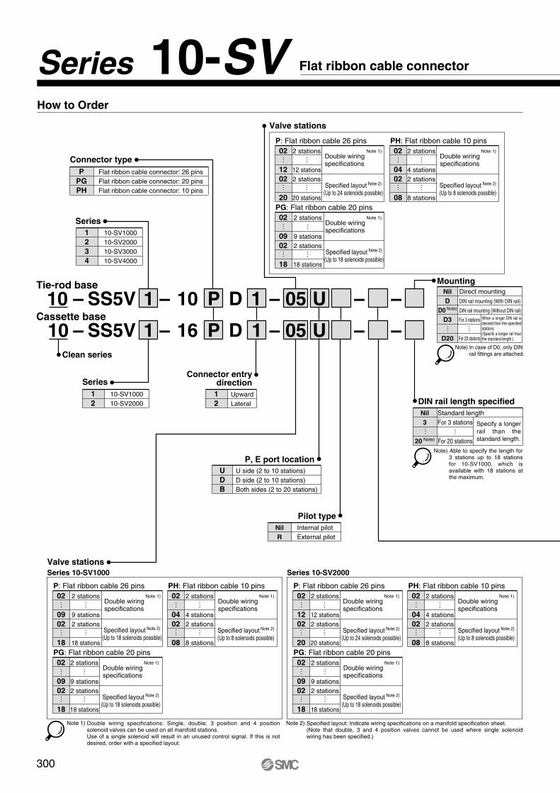
Tie-rod base
Cassette base
Series
–1 D
1
2
10-SV1000
10-SV2000
– – – –1 05161 D
1P
P
Valve stations
Series 10-SV1000 Series 10-SV2000
DIN rail length specified
Standard lengthNil
3
20 Note)
Connector entrydirection
1
2
Upward
Lateral
Series
1
2
3
4
10-SV1000
10-SV2000
10-SV3000
10-SV4000
P, E port location
U
D
B
U side (2 to 10 stations)
D side (2 to 10 stations)
Both sides (2 to 20 stations)
…For 3 stations
For 20 stations
…
MountingDirect mounting
DIN rail mounting (With DIN rail)
DIN rail mounting (Without DIN rail)
Nil
D
D0 Note)
D3
D20
For 3 stations
For 20 stations
… …
Pilot type
Internal pilot
External pilot
Nil
R
Connector type
Flat ribbon cable connector: 26 pins
Flat ribbon cable connector: 20 pins
Flat ribbon cable connector: 10 pins
P
PG
PH
Note 1)
Note) In case of D0, only DIN rail fittings are attached.
P: Flat ribbon cable 26 pins
Double wiring Note 1)
specifications
Specified layout Note 2)
(Up to 18 solenoids possible)
02
09
02
18
……
2 stations
9 stations
2 stations
18 stations
……
– – –05 U10
U
PH: Flat ribbon cable 10 pins
Double wiring Note 1)
specifications
Specified layout Note 2)
(Up to 8 solenoids possible)
02
04
02
08
……
2 stations
4 stations
2 stations
8 stations
……
PG: Flat ribbon cable 20 pins
Double wiring Note 1)
specifications
Specified layout Note 2)
(Up to 18 solenoids possible)
02
09
02
18
……
2 stations
9 stations
2 stations
18 stations
……
Valve stations
P: Flat ribbon cable 26 pins
Double wiring Note 1)
specifications
Specified layout Note 2)
(Up to 24 solenoids possible)
02
12
02
20
……
2 stations
12 stations
2 stations
20 stations
……
PH: Flat ribbon cable 10 pins
Double wiring Note 1)
specifications
Specified layout Note 2)
(Up to 8 solenoids possible)
02
04
02
08
……
2 stations
4 stations
2 stations
8 stations
……
PG: Flat ribbon cable 20 pins
Double wiring Note 1)
specifications
Specified layout Note 2)
(Up to 18 solenoids possible)
02
09
02
18
……
2 stations
9 stations
2 stations
18 stations
……
Note 2)
P: Flat ribbon cable 26 pins
Double wiring Note 1)
specifications
Specified layout Note 2)
(Up to 24 solenoids possible)
02
12
02
20
……
2 stations
12 stations
2 stations
20 stations
……
PH: Flat ribbon cable 10 pins
Double wiring Note 1)
specifications
Specified layout Note 2)
(Up to 8 solenoids possible)
02
04
02
08
……
2 stations
4 stations
2 stations
8 stations
……
PG: Flat ribbon cable 20 pins
Double wiring Note 1)
specifications
Specified layout Note 2)
(Up to 18 solenoids possible)
02
09
02
18
……
2 stations
9 stations
2 stations
18 stations
……
Note) Able to specify the length for 3 stations up to 18 stations for 10-SV1000, which is available with 18 stations at the maximum.
SS5V
SS5VClean series
Series 10-SV Flat ribbon cable connector
How to Order
–
–
10
10
300
When a longer DIN rail is desired than the specified stations. (Specify a longer rail than the standard length.)
Specify a longer
rail than the
standard length.
Double wiring specifications: Single, double, 3 position and 4 position solenoid valves can be used on all manifold stations.Use of a single solenoid will result in an unused control signal. If this is not desired, order with a specified layout.
Specified layout: Indicate wiring specifications on a manifold specification sheet.(Note that double, 3 and 4 position valves cannot be used where single solenoid wiring has been specified.)
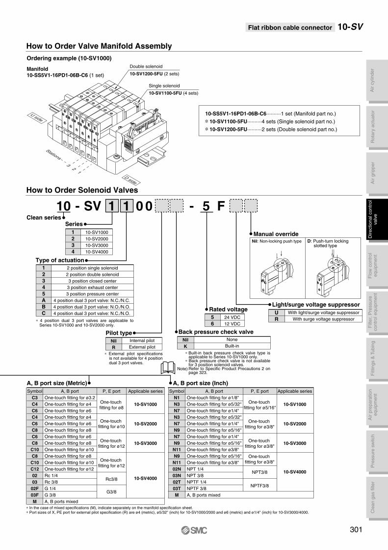
Air c
ylin
der
Rota
ry a
ctu
ato
rA
ir g
ripper
Directional contr
ol
valv
eF
ittings &
Tubin
gP
ressure
sw
itch
Cle
an g
as filt
er
Flo
w c
ontr
ol
equip
ment
Filt
er,
Pre
ssure
contr
ol equip
ment
Air p
repara
tion
equip
ment
Flat ribbon cable connector 10-SV
A, B port size (Inch)
Symbol
N1
N3
N7
N3
N7
N9
N7
N9
N11
N9
N11
02N
03N
02T
03T
M
One-touch fitting for ø1/8"
One-touch fitting for ø5/32"
One-touch fitting for ø1/4"
One-touch fitting for ø5/32"
One-touch fitting for ø1/4"
One-touch fitting for ø5/16"
One-touch fitting for ø1/4"
One-touch fitting for ø5/16"
One-touch fitting for ø3/8"
One-touch fitting for ø5/16"
One-touch fitting for ø3/8"
NPT 1/4
NPT 3/8
NPTF 1/4
NPTF 3/8
A, B ports mixed
One-touch
fitting for ø5/16"
P, E port Applicable series
10-SV1000
10-SV2000
10-SV3000
10-SV4000
One-touch
fitting for ø3/8"
One-touch
fitting for ø3/8"
One-touch
fitting for ø3/8"
NPT3/8
NPTF3/8
A, B port size (Metric)
A, B port A, B portSymbol
C3
C4
C6
C4
C6
C8
C6
C8
C10
C8
C10
C12
02
03
02F
03F
M
One-touch fitting for ø3.2
One-touch fitting for ø4
One-touch fitting for ø6
One-touch fitting for ø4
One-touch fitting for ø6
One-touch fitting for ø8
One-touch fitting for ø6
One-touch fitting for ø8
One-touch fitting for ø10
One-touch fitting for ø8
One-touch fitting for ø10
One-touch fitting for ø12
Rc 1/4
Rc 3/8
G 1/4
G 3/8
A, B ports mixed
One-touch
fitting for ø8
P, E port Applicable series
10-SV1000
10-SV2000
10-SV3000
10-SV4000
One-touch
fitting for ø10
One-touch
fitting for ø12
One-touch
fitting for ø12
Rc3/8
G3/8
How to Order Valve Manifold Assembly
Ordering example (10-SV1000)
Manifold10-SS5V1-16PD1-06B-C6 (1 set)
10-SS5V1-16PD1-06B-C6··········1 set (Manifold part no.)
10-SV1100-5FU··········4 sets (Single solenoid part no.)
10-SV1200-5FU··········2 sets (Double solenoid part no.)
Manual override
Rated voltage
Nil: Non-locking push type D: Push-turn locking slotted type
-1 1 0 0 F5
5
6
24 VDC
12 VDC
Light/surge voltage suppressor
With light/surge voltage suppressor
With surge voltage suppressor
U
R
Pilot type
∗ External pilot specifications is not available for 4 position dual 3 port valves.
∗ 4 position dual 3 port valves are applicable to Series 10-SV1000 and 10-SV2000 only.
How to Order Solenoid Valves
Internal pilot
External pilot
Nil
R
Back pressure check valve
None
Built-in
Nil
K
Series
1
2
3
4
10-SV1000
10-SV2000
10-SV3000
10-SV4000
Type of actuation
1
2
3
4
5
A
B
C
2 position single solenoid
2 position double solenoid
3 position closed center
3 position exhaust center
3 position pressure center
4 position dual 3 port valve: N.C./N.C.
4 position dual 3 port valve: N.O./N.O.
4 position dual 3 port valve: N.C./N.O.
Double solenoid
10-SV1200-5FU (2 sets)
Single solenoid
10-SV1100-5FU (4 sets)
32
1
Stations
U side
D side
DD
DD
DD
∗ In the case of mixed specifications (M), indicate separately on the manifold specification sheet. ∗ Port sizes of X, PE port for external pilot specification (R) are ø4 (metric), ø5/32" (inch) for 10-SV1000/2000 and ø6 (metric) and ø1/4" (inch) for 10-SV3000/4000.
SVClean series
-10
301
∗ Built-in back pressure check valve type is applicable to Series 10-SV1000 only.
∗ Back pressure check valve is not available for 3 position solenoid valves.Refer to Specific Product Precautions 2 on page 323.
Note)
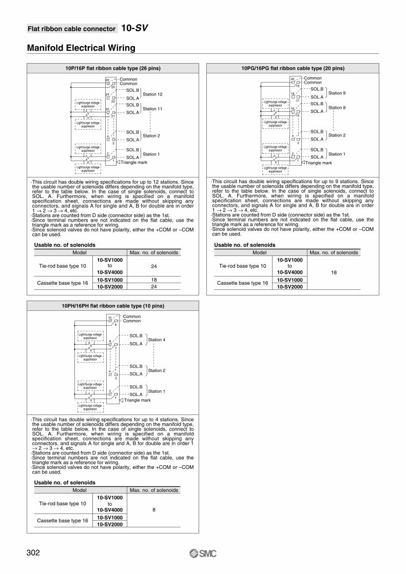
Flat ribbon cable connector 10-SV
10P/16P flat ribbon cable type (26 pins)
Model Max. no. of solenoids
Tie-rod base type 1010-SV1000
10-SV400024
18
24
10-SV1000
10-SV2000Cassette base type 16
Manifold Electrical Wiring
Light/surge voltagesuppressor
Light/surge voltagesuppressor
Light/surge voltagesuppressor
Light/surge voltagesuppressor
Light/surge voltagesuppressor
Light/surge voltagesuppressor
Light/surge voltagesuppressor
Light/Surge voltagesuppressor
Light/surge voltagesuppressor
Light/surge voltagesuppressor
Light/surge voltagesuppressor
Light/surge voltagesuppressor
CommonCommon
SOL.B
SOL.A
SOL.B
SOL.A
SOL.B
SOL.A
SOL.BStation 1
Station 2
Station 11
Station 12
SOL.ATriangle mark
CommonCommon
SOL.B
SOL.A
SOL.B
SOL.A
SOL.B
SOL.A
SOL.BStation 1
Station 2
Station 8
Station 9
SOL.A
Triangle mark
CommonCommon
SOL.B
SOL.A
SOL.B
SOL.A
SOL.BStation 1
Station 2
Station 4
SOL.A
Triangle mark
Usable no. of solenoids
to
26
25
20
19
18
17
16
15
4
3
2
1
10
9
8
7
4
3
2
1
24
23
22
21
4
3
2
1
10PH/16PH flat ribbon cable type (10 pins)
Model Max. no. of solenoids
Tie-rod base type 1010-SV1000
10-SV4000 8
10-SV1000
10-SV2000Cassette base type 16
Usable no. of solenoids
to
10PG/16PG flat ribbon cable type (20 pins)
Model Max. no. of solenoids
Tie-rod base type 1010-SV1000
10-SV4000 18
10-SV1000
10-SV2000Cassette base type 16
Usable no. of solenoids
to
302
·This circuit has double wiring specifications for up to 12 stations. Since the usable number of solenoids differs depending on the manifold type, refer to the table below. In the case of single solenoids, connect to SOL. A. Furthermore, when wiring is specified on a manifold specification sheet, connections are made without skipping any connectors, and signals A for single and A, B for double are in order 1 → 2 → 3 → 4, etc.·Stations are counted from D side (connector side) as the 1st.·Since terminal numbers are not indicated on the flat cable, use the triangle mark as a reference for wiring. ·Since solenoid valves do not have polarity, either the +COM or –COM can be used.
·This circuit has double wiring specifications for up to 9 stations. Since the usable number of solenoids differs depending on the manifold type, refer to the table below. In the case of single solenoids, connect to SOL. A. Furthermore, when wiring is specified on a manifold specification sheet, connections are made without skipping any connectors, and signals A for single and A, B for double are in order 1 → 2 → 3 → 4, etc.·Stations are counted from D side (connector side) as the 1st.·Since terminal numbers are not indicated on the flat cable, use the triangle mark as a reference for wiring. ·Since solenoid valves do not have polarity, either the +COM or –COM can be used.
·This circuit has double wiring specifications for up to 4 stations. Since the usable number of solenoids differs depending on the manifold type, refer to the table below. In the case of single solenoids, connect to SOL. A. Furthermore, when wiring is specified on a manifold specification sheet, connections are made without skipping any connectors, and signals A for single and A, B for double are in order 1 → 2 → 3 → 4, etc.·Stations are counted from D side (connector side) as the 1st.·Since terminal numbers are not indicated on the flat cable, use the triangle mark as a reference for wiring. ·Since solenoid valves do not have polarity, either the +COM or –COM can be used.

Flat ribbon cable connector 10-SV
Dimensions: Series 10-SV1000 for flat ribbon cable
• Cassette base manifold: 10-SS5V1-16 D
· When P, E port outlets are indicated on the U side or D side, the P, E ports on the opposite side are plugged.
· External pilot port positions are the same as P, E port outlet positions.
L1
L2
L3
L4
Ln 2
135.5
125
93.5
24.5
5
160.5
150
125
21
6
173
162.5
135.5
22
7
185.5
175
146
23
8
198
187.5
156.5
24
9
198
187.5
167
19
10
210.5
200
177.5
20
11
223
212.5
188
21
12
235.5
225
198.5
22
13
248
237.5
209
23
14
260.5
250
219.5
24
15
260.5
250
230
18.5
16
273
262.5
240.5
19.5
17
285.5
275
251
20.5
18
298
287.5
261.5
21.5
4
148
137.5
114.5
20
3
135.5
125
104
19
L Dimension n: Stations
Manual override
Press and turn forthe locking type. ( )
4(A) port side: Orange2(B) port side: Green
(Pitch)
(Rail mounting hole pitch: 12.5)
DIN rail holding screw
(Station n) (Station 1)
One-touch fitting
[1(P), 3/5(E) port]Applicable tubing O.D.: ø8
ø5/16" One-touch fitting
[4(A), 2(B) port]Applicable tubing O.D.: ø3.2, ø1/8"
ø4, ø5/32"ø6, ø1/4"
U side D side
P1
5 3 E
P1
5 3 E
B
A
2
4
B
A
2
4
B
A
2
4
B
A
2
4
B
A
2
4
One-touch fitting
[X: External pilot port]Applicable tubing O.D.: ø4
ø5/32"
One-touch fitting
[PE: Pilot EXH port]Applicable tubing O.D.: ø4
ø5/32"
(Lateral connector entry)
Applicable connector: 26 pinsMIL type
(Conforming to MIL-C-83503)
Connector case
Release lever (Both sides)
P1
5 3 E
Triangle mark position
Light/surge voltage suppressor
Block separation lever
With external pilot specifications
B
A
2
4
B
A
2
4
B
A
2
4
B
A
2
4
B
A
2
4
A
B
A
B
A
B
A
B
AB
A
B
AB
P1
5 3 E
PE
X
PE
X
16PG (20 pins)
Triangle mark positionTriangle mark position
Applicable connector: 20 pins MIL type
(Conforming to MIL-C-83503)
16PH (10 pins)
Applicable connector: 10 pins MIL type
(Conforming to MIL-C-83503)
P=10.5
(4.9
)
28.8
(C6:3
.2)
(N7:7
)
83.7
92.2
18
19.7
48
10
23
63
7.5
12
.6
28
.6
13.5
42.3
16.6
36.9
58.4
8
L3
5.5
22.3 33.8
45
.5
59
L2
L1
5
35
(L4)
9.9
74.1
(18.9)
(49.3
)
18.1 8.4
Refer to page 293 (compliant for D-sub
connector) for dimensions with individual
SUP/EXH spacer.
303
12
PPGPH
-UDB
C3, N1C4, N3C6, N7
(R) -Stations
Air c
ylin
der
Rota
ry a
ctu
ato
rA
ir g
ripper
Directional contr
ol
valv
eF
ittings &
Tubin
gP
ressure
sw
itch
Cle
an g
as filt
er
Flo
w c
ontr
ol
equip
ment
Filt
er,
Pre
ssure
contr
ol equip
ment
Air p
repara
tion
equip
ment

Flat ribbon cable connector 10-SV
Dimensions: Series 10-SV2000 for Flat Ribbon Cable
• Cassette base manifold: 10-SS5V2-16 D -
L1
L2
L3
L4
Ln 2
148
137.5
109.5
22.5
5
198
187.5
157.5
23.5
6
210.5
200
173.5
22
7
223
212.5
189.5
20
8
235.5
225
205.5
18.5
9
260.5
250
221.5
23
10
273
262.5
237.5
21
11
285.5
275
253.5
19.5
12
310.5
300
269.5
24
13
323
312.5
285.5
22
14
335.5
325
301.5
20.5
15
348
337.5
317.5
18.5
16
373
362.5
333.5
23
17
385.5
375
349.5
21.5
18
398
387.5
365.5
19.5
19
423
412.5
381.5
24
20
435.5
425
397.5
22.5
4
173
162.5
141.5
19
3
160.5
150
125.5
21
L Dimension n: Stations
· When P, E port outlets are indicated on the U side or D side, the P, E ports on the opposite side are plugged.
· External pilot port positions are the same as P, E port outlet positions.
16PG (20 pins)
Triangle mark position
16PH (10 pins)
Triangle mark position
Applicable connector: 10 pins MIL type
(Conforming to MIL-C-83503)
Refer to page 294 (compliant for D-sub
connector) for dimensions with individual
SUP/EXH spacer.
304
Manual override
Press and turn forthe locking type. ( )
4(A) port side: Orange2(B) port side: Green
(Station n) (Station 1)
(Rail mounting hole pitch: 12.5)
One-touch fitting
[1(P), 3/5(E) port]Applicable tubing O.D.: ø10
ø3/8"
One-touch fitting
[4(A), 2(B) port]Applicable tubing O.D.: ø4, ø5/32"
ø6, ø1/4"ø8, ø5/16"
(Pitch)
DIN rail holding screw
With external pilot specifications
U side D side
Connector case
Release lever (Both sides)
(Lateral connector entry)
Applicable connector: 26 pins MIL type
(Conforming to MIL-C-83503)
Triangle mark position
One-touch fitting
[PE: Pilot EXH port]Applicable tubing O.D.: ø4
ø5/32"
One-touch fitting
[X: External pilot port]Applicable tubing O.D.: ø4
ø5/32"
Light/surge voltage suppressor
Block separation lever
Applicable connector: 20 pins MIL type
(Conforming to MIL-C-83503)
19.7
56.571.5
7.5
L2
L1
5
5.5
27.3
39.5
35
102.9
115.5
23.5
12
.5
15
.93
1.5
34
.6
P=16 17.5
(49.3
) 74.1
L3 (L4)
9.9
42.3
16.6
69.1
8
35
53
.9
67
.5
(5.3
)
18.8 9.5
(18.9)
43.1
(4.9
)
44.5
12
PPGPH
UDB
C4, N3C6, N7C8, N9
(R) -Stations

Air c
ylin
der
Rota
ry a
ctu
ato
rA
ir g
ripper
Directional contr
ol
valv
eF
ittings &
Tubin
gP
ressure
sw
itch
Cle
an g
as filt
er
Flo
w c
ontr
ol
equip
ment
Filt
er,
Pre
ssure
contr
ol equip
ment
Air p
repara
tion
equip
ment
Flat ribbon cable connector 10-SV
Dimensions: Series 10-SV1000 for Flat Ribbon Cable
• Tie-rod base manifold: 10-SS5V1-10 D
· When P, E port outlets are indicated on the U side or D side, the P, E ports on the opposite side are plugged.
· External pilot port positions are the same as P, E port outlet positions.
L1
L2
L3
L4
L5
Ln 2
123
112.5
90.5
19.5
63
5
160.5
150
122
22.5
94.5
6
173
162.5
132.5
23.5
105
7
173
162.5
143
18.5
115.5
8
185.5
175
153.5
19.5
126
9
198
187.5
164
20.5
136.5
10
210.5
200
174.5
21.5
147
11
223
212.5
185
22.5
157.5
12
235.5
225
195.5
23.5
168
13
248
237.5
206
24.5
178.5
14
248
237.5
216.5
19
189
15
260.5
250
227
20
199.5
16
273
262.5
237.5
21
210
17
285.5
275
248
22
220.5
18
298
287.5
258.5
23
231
19
310.5
300
269
24
241.5
20
310.5
300
279.5
19
252
4
148
137.5
111.5
21.5
84
3
135.5
125
101
20.5
73.5
L Dimension n: Stations
Manual override
Press and turn forthe locking type. ( )
4(A) port side: Orange2(B) port side: Green
A
B
A
B
A
B
A
B
A
B
AB
AB
(Pitch)
One-touch fitting
[1(P), 3/5(E) port]
Applicable tubing O.D.: ø8ø5/16"
B 2
A 4
B 2 B 2 B 2 B 2
A 4 A 4 A 4 A 4
Triangle mark position
DIN rail holding screw
(For DIN rail mounting)
(Station n) (Station 1)
(Rail mounting hole pitch: 12.5)
One-touch fitting
[4(A), 2(B) port]Applicable tubing O.D.: ø3.2, ø1/8"
ø4, ø5/32"ø6, ø1/4"
Applicable connector: 26 pins MIL type
(Conforming to MIL-C-83503)
Connector case
Release lever (Both sides)
(Lateral connector entry)
P1
5 3 E 3/5
1 P
E
B 2
A 4
B 2 B 2 B 2 B 2
A 4 A 4 A 4 A 4
1 P
5 3 E
One-touch fitting
[PE: Pilot EXH port]Applicable tubing O.D.: ø4
ø5/32"
One-touch fitting
[X: External pilot port]Applicable tubing O.D.: ø4
ø5/32"
With external pilot specifications
3/5
1 P
E
(For
DIN
rail
mounting)
U side D side
4-ø4.3
(For mounting)
Light/surge voltage suppressor
10PG (20 pins)
Triangle mark position
Applicable connector: 20 pins MIL type
(Conforming to MIL-C-83503)
10PH (10 pins)
Triangle mark position
Applicable connector: 10 pins MIL type
(Conforming to MIL-C-83503)
PE
X
PE
X
(7.5
)
83.7
92.2
8
18.3
45.5
8.6
24
.6
(4.9
)
(C6:3
.2)
(N7:7
)
13.5P=10.5
10
23
(39.6
) 64.4
(18.9)
L5
34.8
L3
9.9
10
59.5
43
56
.5
11.8
83
4.6
L2
L1
5
35
5.5
(L4)
29.6
10.8
39.6
8.9
58.9 9
2.6
22
14.1 8.4
Refer to page 295 (compliant for D-sub
connector) for dimensions with individual
SUP/EXH spacer.
305
12
PPGPH
-UDB
C3, N1C4, N3C6, N7
(R) -Stations

Flat ribbon cable connector 10-SV
Dimensions: Series 10-SV2000 for Flat Ribbon Cable
• Tie-rod base manifold: 10-SS5V2-10 D12
PPGPH
-UDB
C4, N3C6, N7C8, N9
(R) -Stations
· When P, E port outlets are indicated on the U side or D side, the P, E ports on the opposite side are plugged.
· External pilot port positions are the same as P, E port outlet positions.
L1
L2
L3
L4
L5
Ln 2
148
137.5
106.4
24
80
5
185.5
175
154.4
19
128
6
210.5
200
170.4
23.5
144
7
223
212.5
186.4
21.5
160
8
235.5
225
202.4
20
176
9
248
237.5
218.4
18
192
10
273
262.5
234.4
22.5
208
11
285.5
275
250.4
21
224
12
298
287.5
266.4
19
240
13
323
312.5
282.4
23.5
256
14
335.5
325
298.4
22
272
15
348
337.5
314.4
20
288
16
360.5
350
330.4
18.5
304
17
385.5
375
346.4
23
320
18
398
387.5
362.4
21
336
19
410.5
400
378.4
19.5
352
20
435.5
425
394.4
24
368
4
173
162.5
138.4
20.5
112
3
160.5
150
122.4
22.5
96
L Dimension n: Stations
Manual override
Press and turn for the locking type. ( )
4(A) port side: Orange2(B) port side: Green
P1
E3/5 3/5
B
A
2
4
B
A
2
4
B
A
2
4
B
A
2
4
B
A
2
4
(Station n) (Station 1)
DIN rail holding screw
(Rail mounting hole pitch: 12.5)
(Pitch)
One-touch fitting
[1(P), 3/5(E) port]Applicable tubing O.D.: ø10
ø3/8"
One-touch fitting
[4(A), 2(B) port]
Applicable tubing O.D.: ø4, ø5/32"ø6, ø1/4"ø8, ø5/16"
A
B
AB
A
B
A
B
A
B
A
B
AB
1 P
E
(For
DIN
rail
mounting)
U side D side
Triangle mark position
P1
E3/5 3/5
B
A
2
4
B
A
2
4
B
A
2
4
B
A
2
4
B
A
2
4
1 P
E
Connector case
Release lever (Both sides)
(Lateral connector entry)
Applicable connector: 26 pins MIL type
(Conforming to MIL-C-83503)
One-touch fitting
[PE: Pilot EXH port]Applicable tubing O.D.: ø4
ø5/32"
One-touch fitting
[X: External pilot port]Applicable tubing O.D.: ø4
ø5/32"
4-ø5.3
(For mounting)
Light/surge voltage suppressor
With external pilot specifications
PE
X
PE
X
10PG (20 pins)
Triangle mark position
Applicable connector: 20 pins MIL type
(Conforming to MIL-C-83503)
10PH (10 pins)
Triangle mark position
Applicable connector: 10 pins MIL type
(Conforming to MIL-C-83503)
12
52.563.5
115.5
L5
20.5
9.2
25
.2
17.5P=16
(7.5
)(4
1.6
) 66.4
(18.9)
L2
L1
5
L3 (L4)
(4.9
)
5.4
34.9
49
.9
63
.5
11.8
11
.9
30
.6
29.6
12.2
5.5
35
58.9
11.4
109.4
20.4
9.9
(5.3
)
53.4
15.8 9.5
97.5
102.9
(For DIN rail mounting)
Refer to page 296 (compliant for D-sub
connector) for dimensions with individual
SUP/EXH spacer.
8
306
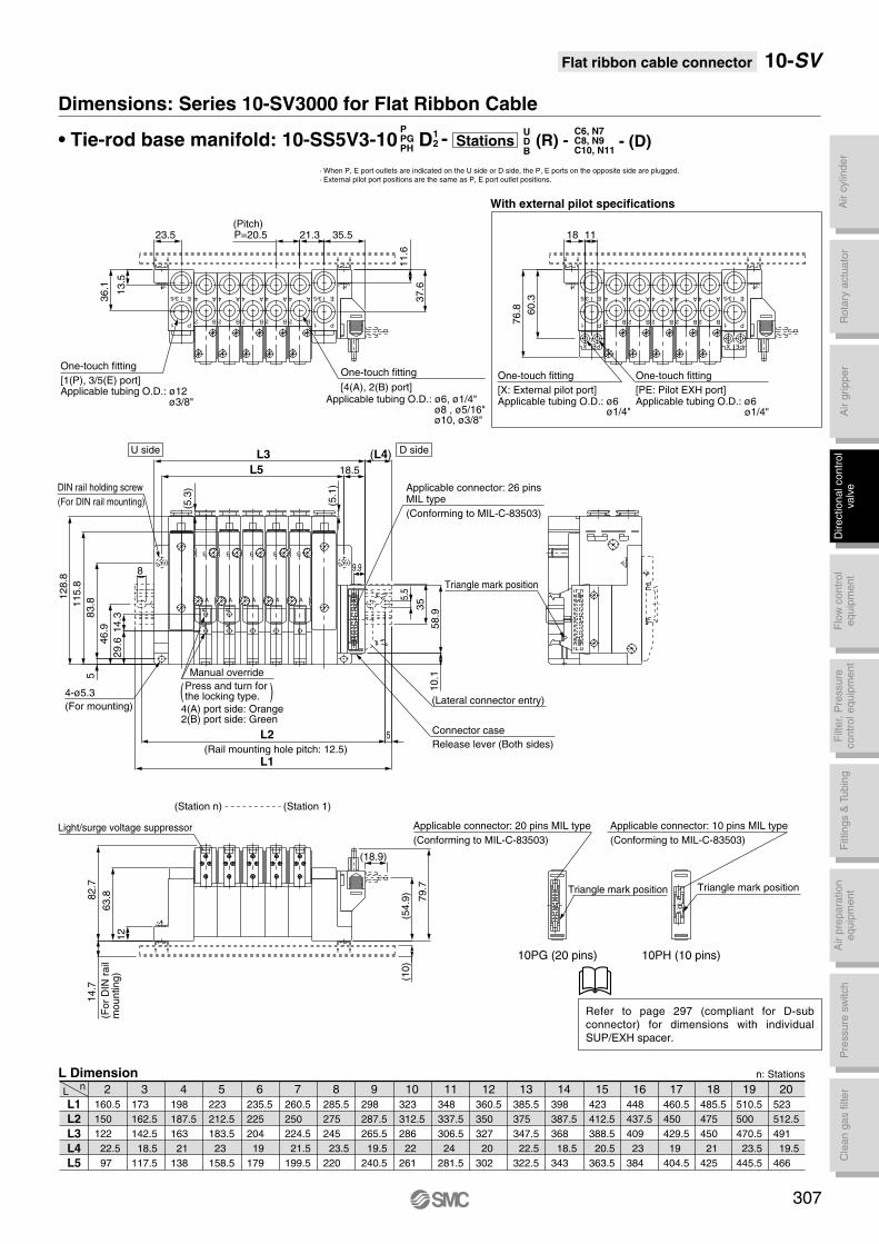
Air c
ylin
der
Rota
ry a
ctu
ato
rA
ir g
ripper
Directional contr
ol
valv
eF
ittings &
Tubin
gP
ressure
sw
itch
Cle
an g
as filt
er
Flo
w c
ontr
ol
equip
ment
Filt
er,
Pre
ssure
contr
ol equip
ment
Air p
repara
tion
equip
ment
Flat ribbon cable connector 10-SV
Dimensions: Series 10-SV3000 for Flat Ribbon Cable
• Tie-rod base manifold: 10-SS5V3-10 D
· When P, E port outlets are indicated on the U side or D side, the P, E ports on the opposite side are plugged.
· External pilot port positions are the same as P, E port outlet positions.
L1
L2
L3
L4
L5
Ln 2
160.5
150
122
22.5
97
5
223
212.5
183.5
23
158.5
6
235.5
225
204
19
179
7
260.5
250
224.5
21.5
199.5
8
285.5
275
245
23.5
220
9
298
287.5
265.5
19.5
240.5
10
323
312.5
286
22
261
11
348
337.5
306.5
24
281.5
12
360.5
350
327
20
302
13
385.5
375
347.5
22.5
322.5
14
398
387.5
368
18.5
343
15
423
412.5
388.5
20.5
363.5
16
448
437.5
409
23
384
17
460.5
450
429.5
19
404.5
18
485.5
475
450
21
425
19
510.5
500
470.5
23.5
445.5
20
523
512.5
491
19.5
466
4
198
187.5
163
21
138
3
173
162.5
142.5
18.5
117.5
L Dimension n: Stations
Manual override
Press and turn forthe locking type. ( )
4(A) port side: Orange2(B) port side: Green
(Station n) (Station 1)
DIN rail holding screw
(For DIN rail mounting)
(Rail mounting hole pitch: 12.5)
(Pitch)
One-touch fitting
[1(P), 3/5(E) port]Applicable tubing O.D.: ø12
ø3/8"
(For
DIN
rail
mounting)
4-ø5.3
(For mounting)
Connector case
Release lever (Both sides)
(Lateral connector entry)
Applicable connector: 26 pins MIL type
(Conforming to MIL-C-83503)
Triangle mark position
U side D side
One-touch fitting
[4(A), 2(B) port]Applicable tubing O.D.: ø6, ø1/4"
ø8 , ø5/16"ø10, ø3/8"
One-touch fitting
[X: External pilot port]Applicable tubing O.D.: ø6
ø1/4"
One-touch fitting
[PE: Pilot EXH port]Applicable tubing O.D.: ø6
ø1/4"
Light/surge voltage suppressor
E
1 P
35
2 B
4 A
2 B
4 A
2 B
4 A
2 B
4 A
2 B
4 A E
1 P
35 E
1 P
35
2 B
4 A
2 B
4 A
2 B
4 A
2 B
4 A
2 B
4 A E
1 P
35
AB
A
B
AB
A
B
A
B
A
B
A
B
X PE X PE
10PG (20 pins)
Triangle mark position
Applicable connector: 20 pins MIL type
(Conforming to MIL-C-83503)
10PH (10 pins)
Triangle mark position
Applicable connector: 10 pins MIL type
(Conforming to MIL-C-83503)
With external pilot specifications
12
63.882.7
115.8
128.8
L5
21.3P=20.523.5
13
.5
36
.1
11
.6
37
.6
83.8
5
(5.1
)
(L4)L3
5L2
L1
14.7
(10)
(54.9
)
79.7
(18.9)
9.9
35.5
8
60
.3
76
.8
18.5
29.6
14.3
46.9
5.5
35
58.9
10.1
(5.3
)
18 11
Refer to page 297 (compliant for D-sub
connector) for dimensions with individual
SUP/EXH spacer.
307
- (D)12
PPGPH
-UDB
C6, N7C8, N9C10, N11
(R) -Stations
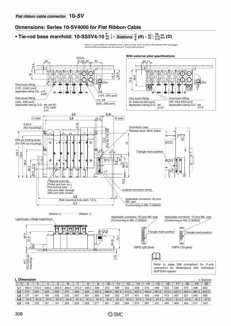
Flat ribbon cable connector 10-SV
Dimensions: Series 10-SV4000 for Flat Ribbon Cable
• Tie-rod base manifold: 10-SS5V4-10
· When P, E port outlets are indicated on the U side or D side, the P, E ports on the opposite side are plugged.
· External pilot port positions are the same as P, E port outlet positions.
L1
L2
L3
L4
L5
Ln 2
185.5
175
137
31.5
109
5
260.5
250
209
31.5
181
6
285.5
275
233
31.5
205
7
310.5
300
257
31.5
229
8
335.5
325
281
31.5
253
9
348
337.5
305
31.5
277
10
373
362.5
329
31.5
301
11
398
387.5
353
31.5
325
12
423
412.5
377
31.5
349
13
448
437.5
401
31.5
373
14
473
462.5
425
31.5
397
15
498
487.5
449
31.5
421
16
523
512.5
473
31.5
445
17
548
537.5
497
31.5
469
18
573
562.5
521
31.5
493
19
598
587.5
545
31.5
517
20
623
612.5
569
31.5
541
4
235.5
225
185
31.5
157
3
210.5
200
161
31.5
133
L Dimension n: Stations
10PG (20 pins)
Triangle mark position
Applicable connector: 20 pins MIL type
(Conforming to MIL-C-83503)
10PH (10 pins)
Triangle mark position
Applicable connector: 10 pins MIL type
(Conforming to MIL-C-83503)
Refer to page 298 (compliant for D-sub
connector) for dimensions with individual
SUP/EXH spacer.
308
Manual override
Press and turn for the locking type. ( )4(A) port side: Orange2(B) port side: Green
(Pitch)
U side D side
One-touch fitting
[1(P), 3/5(E) port]Applicable tubing O.D.: ø12
ø3/8"
One-touch fitting
[4(A), 2(B) port]Applicable tubing O.D.: ø8, ø5/16"
ø10, ø3/8"ø12
DIN rail holding screw
(For DIN rail mounting)
4-ø6.2
(For mounting)
(Rail mounting hole pitch: 12.5)
Connector case
Release lever (Both sides)
(Lateral connector entry)
Applicable connector: 26 pinsMIL type
(Conforming to MIL-C-83503)
Light/surge voltage suppressor
(Station n) (Station 1)
Triangle mark position
(For
DIN
rail
mounting)
One-touch fitting
[X: External pilot port]Applicable tubing O.D.: ø6
ø1/4"
One-touch fitting
[PE: Pilot EXH port]Applicable tubing O.D.: ø6
ø1/4"[F
or
Rc 1
/4,
3/8
]
1/4, 3/8
[4(A), 2(B) port]
3/8
[1(P), 3(E) port]
With external pilot specifications
4024P=24
14
.53
5
13
.7
35
.8
(5.4
)
L5
L3
21.5
9.9
12.2
17.5
29.6
56.3
98.2
148.2
164.7
16.2
61.88
5.5
14.7
(10)
70.7
(45.9
)
(18.9)
11
58
.3
74
.8
2025
5.5
35
8
58.9
75
81.7
L2 5
L1
(L4)
13.3
02,03,
C8,C10,C12,
N9N11 (D)1
2
PPGPH
-UDB
(R) -Stations

Air c
ylin
der
Rota
ry a
ctu
ato
rA
ir g
ripper
Directional contr
ol
valv
eF
ittings &
Tubin
gP
ressure
sw
itch
Cle
an g
as filt
er
Flo
w c
ontr
ol
equip
ment
Filt
er,
Pre
ssure
contr
ol equip
ment
Air p
repara
tion
equip
ment
Relay output module
How to Order
Relay output module specifications
By adding a relay output module to a series 10-SV manifold, devices up to 110 VAC, 3 A (large type solenoid valves, etc.)
can be controlled together with Series 10-SV valves.
SV 000 60 A5 1A
Series
1
2
3
4
10-SV1000
10-SV2000
10-SV3000
10-SV4000
No. of outputpoints
A
B
1 output
2 outputs
Rated voltage
5
6
24 VDC
12 VDC
- - -
Y type connector
How to Order
Relay output module and Y type connector wiring example
Used to branch a two output relay output module to two separate systems.
EX500 ACY00 S- -
Relay output module
Light window
2
4
2 1
3 4
2
4
2 1
3 4
1
3
Item Specifications
Based on IP67 (IEC60529)
20 mA or less
Non-polar
48
Orange
No. of output points
Output type
Load voltage
Load current
Indicator light
Enclosure
Current consumption
Polarity
Weight (g)
1 output [connector with lead wire (M12)]
4 pins connector (M12) plug
Contact type
("a" contact)
Relay output module side
pin arrangement
1. —
2. Output A
3. —
4. Output A
4 pins connector (M12) plug
Contact type
("a" contact)
Relay output module side
pin arrangement
1. Output B
2. Output A
3. Output B
4. Output A
2 outputs [connector with lead wire (M12)]
A side: Orange B side: Green
110 VAC
0.3A
30 VDC
3A
110 VAC
3A
30 VDC
1A
2
Output A
Output B
Relay output module(2 outputs)
Y type connector
4
1
3
2
4
2
4
Sole
noid
Sole
noid
∗ Note that serial wiring manifolds (EX500, EX250 and EX120) are available with 24 VDC only.
Manifold Option (Common for type 16 and 10)
309
Series 10-SV
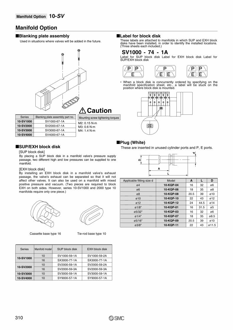
Manifold Option 10-SV
Manifold Option
Blanking plate assemblyUsed in situations where valves will be added in the future.
Label for block disk
SUP/EXH block disk[SUP block disk]
Series
10-SV1000
10-SV2000
10-SV3000
10-SV4000
Blanking plate assembly part no.
SV1000-67-1A
SV2000-67-1A
SV3000-67-1A
SV4000-67-1A
Series
10-SV1000
10-SV2000
10-SV3000
10-SV4000
Manifold model
Cassette base type 16 Tie-rod base type 10
10
16
10
16
10
10
SV1000-59-1A
SX3000-77-1A
SV2000-59-1A
SV2000-59-3A
SV3000-59-1A
SY9000-57-1A
SUP block disk
SV1000-59-2A
SX3000-77-1A
SV2000-59-2A
SV2000-59-3A
SV3000-59-1A
SY9000-57-1A
EXH block disk
SV1000 74 1A- -
[EXH block disk]
Mounting screw tightening torques
M2: 0.15 N·mM3: 0.6 N·mM4: 1.4 N·m
Caution
Plug (White)These are inserted in unused cylinder ports and P, E ports.
ø4
ø6
ø8
ø10
ø12
ø1/8"
ø5/32"
ø1/4"
ø5/16"
ø3/8"
D
ø6
ø8
ø10
ø12
ø14
ø5
ø6
ø8.5
ø10
ø11.5
L
32
35
39
43
44.5
31.5
32
35
39
43
A
16
18
20.5
22
24
16
16
18
20.5
22
Model
10-KQP-04
10-KQP-06
10-KQP-08
10-KQP-10
10-KQP-12
10-KQP-01
10-KQP-03
10-KQP-07
10-KQP-09
10-KQP-11
Applicable fitting size d
d
A
D
L
310
These labels are attached to manifolds in which SUP and EXH block disks have been installed, in order to identify the installed locations. (Three sheets each included.)
Label for SUP block disk Label for EXH block disk Label for SUP/EXH block disk
∗ When a block disk is concurrently ordered by specifying on the manifold specification sheet, etc., a label will be stuck on the position where block disk is mounted.
By placing a SUP block disk in a manifold valve's pressure supply passage, two different high and low pressures can be supplied to one manifold.
By installing an EXH block disk in a manifold valve's exhaust passage, the valve's exhaust can be separated so that it will not affect other valves. It can also be used on a manifold with mixed positive pressure and vacuum. (Two pieces are required to block EXH on both sides. However, series 10-SV1000 and 2000 type 10 manifolds require only one piece.)

Air c
ylin
der
Rota
ry a
ctu
ato
rA
ir g
ripper
Directional contr
ol
valv
eF
ittings &
Tubin
gP
ressure
sw
itch
Cle
an g
as filt
er
Flo
w c
ontr
ol
equip
ment
Filt
er,
Pre
ssure
contr
ol equip
ment
Air p
repara
tion
equip
ment
Manifold Option
Circular connector / Cable assembly (26 pins) D-sub connector / Cable assembly (25 pins)
When a commercially available connector is required, use a 25 pin female
connector conforming to MIL-C-24308.
Part no.
AXT100-MC26-015
AXT100-MC26-030
AXT100-MC26-050
Lead wire length
L dimension
1.5 m
3 m
5 m
Terminal no.
1
2
3
4
5
6
7
8
9
10
11
12
13
14
15
16
17
18
19
20
21
22
23
24
25
Lead wire color
Black
Brown
Red
Orange
Yellow
Pink
Blue
Purple
Gray
White
White
Yellow
Orange
Yellow
Pink
Blue
Purple
Gray
Orange
Red
Brown
Pink
Gray
Black
White
Dot marking
None
None
None
None
None
None
None
White
Black
Black
Red
Red
Red
Black
Black
White
None
None
Black
White
White
Red
Red
White
None
AXT100 MC26– –
Part no.
AXT100-DS25-015
AXT100-DS25-030
AXT100-DS25-050
Lead wire length
L dimension
1.5 m
3 m
5 m
AXT100 DS25– –
Circular connector cable assemblyTerminal no.
Terminal no.
1
2
3
4
5
6
7
8
9
10
11
12
13
14
15
16
17
18
19
20
21
22
23
24
25
Lead wire color
Black
Brown
Red
Orange
Yellow
Pink
Blue
Purple
Gray
White
White
Yellow
Orange
Yellow
Pink
Blue
Purple
Gray
Orange
Red
Brown
Pink
Gray
Black
White
Dot marking
None
None
None
None
None
None
None
White
Black
Black
Red
Red
Red
Black
Black
White
None
None
Black
White
White
Red
Red
White
None
D-sub connector cable assemblyTerminal no.
Item
Conductor resistance Ω/km, 20°C
Withstand voltage VAC, 1min.
Insulation resistance MΩkm, 20°C
Characteristics
65 or less
1000
5 or less
Note) The minimum inside bending radius for each cable is 20 mm.
Circular connector, D-sub connector cable assembly Electric characteristics
Plug terminal no.(Arrangement as seen from lead wire side)
14
25
11
3 Multi-core vinyl cable
0.3 mm2 x 25C
2-M2.6 x 0.45
Terminal no.Socket side
16
(60)
L
44
L
8
47
.04
55
Ap
pro
x. ø
10
Note) Terminal no. 26 is connected to 25 inside the connector.
Manifold Option 10-SV
311
q!5!4@4!3
!2 @3
@2!1!0
o i
@1
@6
@5
!6!7w
e
r!8
!9
y
t
@0u

Manifold Option
Flat Ribbon Cable / Cable assembly 10-SV1000/2000 and Series EX500 input unit DIN rail dimensions and weights
∗ As for , enter the number from the DIN rail dimensions table.
Connector manufacturers' example
• Hirose Electric Co., Ltd.
• Sumitomo 3M Limited
• Fujitsu Limited
• Japan Aviation Electronics Industry, Ltd.
• J.S.T. Mfg. Co., Ltd.
L dimension
Weight (g)
0
98
17.6
1
110.5
19.9
2
123
22.1
3
135.5
24.4
4
148
26.6
5
160.5
28.9
6
173
31.1
7
185.5
33.4
8
198
35.6
9
210.5
37.9
No.
L dimension
Weight (g)
10
223
40.1
11
235.5
42.4
12
248
44.6
13
260.5
46.9
14
273
49.1
15
285.5
51.4
16
298
53.6
17
310.5
55.9
18
323
58.1
19
335.5
60.4
No.
L dimension
Weight (g)
20
348
62.5
21
360.5
64.9
22
373
67.1
23
385.5
69.4
24
398
71.6
25
410.5
73.9
26
423
76.1
27
435.5
78.4
28
448
80.6
29
460.5
82.9
No.
L dimension
Weight (g)
30
473
85.1
31
485.5
87.4
32
498
89.6
33
510.5
91.9
34
523
94.1
35
535.5
96.4
36
548
98.6
37
560.5
100.9
38
573
103.1
39
585.5
105.4
No.
L dimension
Weight (g)
40
598
107.6
41
610.5
109.9
42
623
112.1
43
635.5
114.4
44
648
116.6
45
660.5
118.9
46
673
121.1
47
685.5
123.4
48
698
125.6
49
710.5
127.9
No.
L dimension
Weight (g)
50
723
130.1
51
735.5
132.4
52
748
134.6
53
760.5
136.9
54
773
139.1
55
785.5
141.4
56
798
143.6
57
810.5
145.9
58
823
148.1
59
835.5
150.4
No.
L dimension
Weight (g)
60
848
152.6
61
860.5
154.9
62
873
157.1
63
885.5
159.4
64
898
161.6
65
910.5
163.9
66
923
166.1
67
935.5
168.4
68
948
170.6
69
960.5
172.9
No.
L dimension
Weight (g)
70
973
175.1
71
985.5
177.4
No.
Cable length (L)
1.5 m
3 m
5 m
Connector width (W)
10 pins
AXT100-FC10-1
AXT100-FC10-2
AXT100-FC10-3
17.2
20 pins
AXT100-FC20-1
AXT100-FC20-2
AXT100-FC20-3
30
26 pins
AXT100-FC26-1
AXT100-FC26-2
AXT100-FC26-3
37.5
AXT100 FC– –VZ1000 11 1– ––
10-SV3000 and 4000 DIN rail dimensions and weights
∗ As for , enter the number from the DIN rail dimensions table.
L dimension
Weight (g)
0
98
24.8
1
110.5
28
2
123
31.1
3
135.5
34.3
4
148
37.4
5
160.5
40.6
6
173
43.8
7
185.5
46.9
8
198
50.1
9
210.5
53.3
No.
L dimension
Weight (g)
10
223
56.4
11
233.5
59.6
12
248
62.7
13
260.5
65.9
14
273
69.1
15
285.5
72.2
16
298
75.4
17
310.5
78.6
18
323
81.7
19
335.5
84.9
No.
L dimension
Weight (g)
20
348
88
21
360.5
91.2
22
373
94.4
23
385.5
97.5
24
398
100.7
25
410.5
103.9
26
423
107
27
435.5
110.2
28
448
113.3
29
460.5
116.5
No.
L dimension
Weight (g)
30
473
119.7
31
485.5
122.8
32
498
126
33
510.5
129.2
34
523
132.3
35
535.5
135.5
36
548
138.6
37
560.5
141.8
38
573
145
39
585.5
148.1
No.
40
598
151.3
41
610.5
154.5
42
623
157.6
63
885.5
224
64
898
227.2
65
910.5
230.4
66
923
233.5
67
935.5
236.7
68
948
239.8
69
960.5
243
70
973
246.2
71
985.5
249.3
43
635.5
160.8
44
648
163.9
45
660.5
167.1
46
673
170.3
47
685.5
173.4
48
698
176.6
49
710.5
179.8
50
723
182.9
51
735.5
186.1
52
748
189.2
53
760.5
192.4
54
773
195.6
55
785.5
198.7
56
798
201.9
57
810.5
205.1
58
823
208.2
59
835.5
211.4
60
848
214.5
61
860.5
217.7
62
873
220.9
VZ1000 11 4– ––
∗ For other commercial connectors, use a type with strain relief conforming
to MIL-C-83503.
12
5
26
2
W
Terminal no.
Red6
(35)
(25)
(10)
5.5
8
L
Rail mounting hole pitch: 12.5
(Rail mounting hole pitch: 12.5)
(35)
(25)
(7.5)L
8
5.5
L
(15.6)
Manifold Option 10-SV
312

Air c
ylin
der
Rota
ry a
ctu
ato
rA
ir g
ripper
Directional contr
ol
valv
eF
ittings &
Tubin
gP
ressure
sw
itch
Cle
an g
as filt
er
Flo
w c
ontr
ol
equip
ment
Filt
er,
Pre
ssure
contr
ol equip
ment
Air p
repara
tion
equip
ment
Manifold Option
Individual SUP spacer assembly Individual EXH spacer assembly
SUP port EXH port
How to order individual SUP/EXH spacer assembly
Series 10-SV1000 Series 10-SV2000/10-SV3000/10-SV4000
SV1000 C638
One-touch fitting for ø3.2One-touch fitting for ø4One-touch fitting for ø6One-touch fitting for ø1/8"One-touch fitting for ø5/32"One-touch fitting for ø1/4"
C3
C4
C6
N1
N3
N7
Port size
1A SV 2 000
Rc
G
NPT
NPTF
Nil
F
N
T
Series
10-SV2000
10-SV3000
10-SV4000
Port size
1/8
1/4
Thread type note)
10-SV2000
10-SV3000
10-SV4000
2
3
4
Series
Individual SUP spacer38
Spacer type
38
Round head combination screw
SX3000-22-9
(M2 x 39.5)
SV2000-21-6
(M3 x 46)
SV3000-21-3
(M4 x 53)
SV2000-21-5
(M3 x 60)
GasketSeries
Accessory
1 A
Note) 10-SV2000/3000/4000 port size
39 Individual EXH spacer
Manifold Option 10-SV
313
SX3000-57-4
SY5000-11-15
SY7000-11-11
SY9000-11-2
10-SV1000
10-SV2000
10-SV3000
10-SV4000

10
Type of actuation
- -W10011 5
Series
1
2
3
4
10-SV1000
10-SV2000
10-SV3000
10-SV4000
Light / Surge voltage suppressor
U
R
With light/surge voltage suppressor
With surge voltage suppressor
Manual override
Non-locking push typeNil
DM12 waterproof connector
5
6
24 VDC
12 VDC
Rated voltage
Nil
R
Internal pilot
External pilot
Pilot type
4 position dual 3 port valves are not available for 10-SV3000 and 10-SV4000.
U D
Port size
Thread type
Symbol
Nil
01
02
03
04
1/8
1/4
3/8
1/2
Applicable series
10-SV1000
10-SV2000
10-SV3000
10-SV3000
10-SV4000
10-SV4000
Port size
Without sub-plate
Nil
F
N
T
Rc
G
NPT
NPTF
Symbol
W1
W2
W3
W4
W7
Cable length (mm)
300
500
1000
2000
5000
1
2
3
4
5
A
C
2 position single solenoid
2 position double solenoid
3 position closed center
3 position exhaust center
3 position pressure center
4 position dual 3 port valve: N.C./N.C.
4 position dual 3 port valve: N.O./N.O.
4 position dual 3 port valve: N.C./N.O.
B
(A)4
(B)2
5(EA)
1(P)
3(EB)
(A)4
(B)2
5(EA)
1(P)
3(EB)
(A)4
(B)2
5(EA)
1(P)
3(EB)
(A)4
(B)2
5(EA)
1(P)
3(EB)
(A)4
(A)4
(A)4
(A)4
(B)2
(B)2
(B)2
(B)2
5(EA)
1(P)
3(EB)
5(EA)
5(EA)
5(EA)
1(P)
1(P)
1(P)
SOL.bSOL.a3
(EB)
3(EB)
3(EB)
SOL.bSOL.a
SOL.bSOL.a
Clean series
Single Valve / Sub-plate Type[IP67 compliant]
How to Order
SV-
4 position dual 3 port valve: N.C./N.C.
4 position dual 3 port valve: N.O./N.O.
4 position dual 3 port valve: N.C./N.O.
(A)4
(A)4
(A)4
(B)2
(B)2
(B)2
5(EA)
5(EA)
5(EA)
1(P)
1(P)
1(P)
SOL.bSOL.a3
(EB)
3(EB)
3(EB)
SOL.bSOL.a
SOL.bSOL.a
Series 10-SV1000 Series 10-SV2000
314
Series 10-SV1000/2000/3000/4000
∗ External pilot specifications is not available for 4 position dual 3 port valves.
Push-turn locking
slotted type

Air c
ylin
der
Rota
ry a
ctu
ato
rA
ir g
ripper
Directional contr
ol
valv
eF
ittings &
Tubin
gP
ressure
sw
itch
Cle
an g
as filt
er
Flo
w c
ontr
ol
equip
ment
Filt
er,
Pre
ssure
contr
ol equip
ment
Air p
repara
tion
equip
ment
Series 10-SV solenoid valve specifications
Note) Based on dynamic performance test, JIS B 8375-1981. (Coil temperature: 20°C, at rated voltage)
Fluid
Ambient and fluid temperature (°C)
Manual override
Pilot exhaust method
Lubrication
Mounting orientation
Impact/Vibration resistance (m/s2)
Enclosure
Electrical entry
Coil rated voltage
Allowable voltage fluctuation
Power consumption (W)
Surge voltage suppressor
Indicator light
Air
0.15 to 0.7
0.1 to 0.7
0.2 to 0.7
–100 kPa to 0.7
0.25 to 0.7
–10 to 50 (No freezing. Refer to page 714.)
5
3
Non-locking push type
Push-turn locking slotted type
Common exhaust type for main and pilot valve
Pilot valve individual exhaust
Not required
Unrestricted
150/30 (8.3 to 2000 Hz)
IP67 (Based on IEC60529)
M12 waterproof connector
24 VDC, 12 VDC
±10% of rated voltage
0.6 (With light: 0.65)
Zener diode
LED
2 position single
4 position dual 3 port valve
2 position double
3 position
Operating pressure range
2 position single, double
3 position
2 position single, double
4 position dual 3 port valve
3 position
Type of actuation
2 position single
2 position double
3 position
4 position dual 3 port valve
10-SV1000
11 or less
10 or less
18 or less
15 or less
10-SV2000
25 or less
17 or less
29 or less
33 or less
10-SV3000
28 or less
26 or less
32 or less
—
10-SV4000
40 or less
40 or less
82 or less
—
Internal pilotoperating pressurerange(MPa)
External pilotoperating pressurerange(MPa)
Max. operating frequency(Hz)
Internal pilot
External pilot
Response time
Response time (ms) (at the pressure of 0.5 MPa)
Single solenoid
4 pins connector (M12) plug 4 pins connector (M12) plug
Double solenoid
M12 waterproof connector wiring specifications
Note) Solenoid valves have no polarity.
3(COM)
4
Circuit diagram Solenoid valve side
pin wiring diagram
2 1
3 4
Circuit diagram
2 1
3 4
Solenoid valve side
pin wiring diagram
Solenoid
4
Solenoid A
3(COM)
2
Solenoid B
Note) Impact resistance: No malfunction occurred when it is tested with a drop tester in the axial direction and
at the right angles to the main valve and armature in both energized and deenergized states every
once for each condition. (Values at the initial period)
Vibration resistance: No malfunction occurred in a one-sweep test between 45 and 2000 Hz. Test was
performed at both energized and de-energized states in the axial direction and at the right angles to
the main valve and armature. (Values at the initial period)
Connector size
M12
Number of pins
4
Manufacturer
Corrence Corporation
OMRON Corporation
Yamatake-Honeywell Co., Ltd.
Hirose Electric Co., Ltd.
DKK Ltd.
Applicable series example
VA-4D
XS2
PA5-41
HR24
CM01-8DP4S
Connection (female side) connector cableAs the parts are not supplied from SMC, refer to the application examples listed in the below.(For detail such as catalog availability, etc., please contact each manufacturer.)
Single Valve / Sub-plate Type 10-SV
315
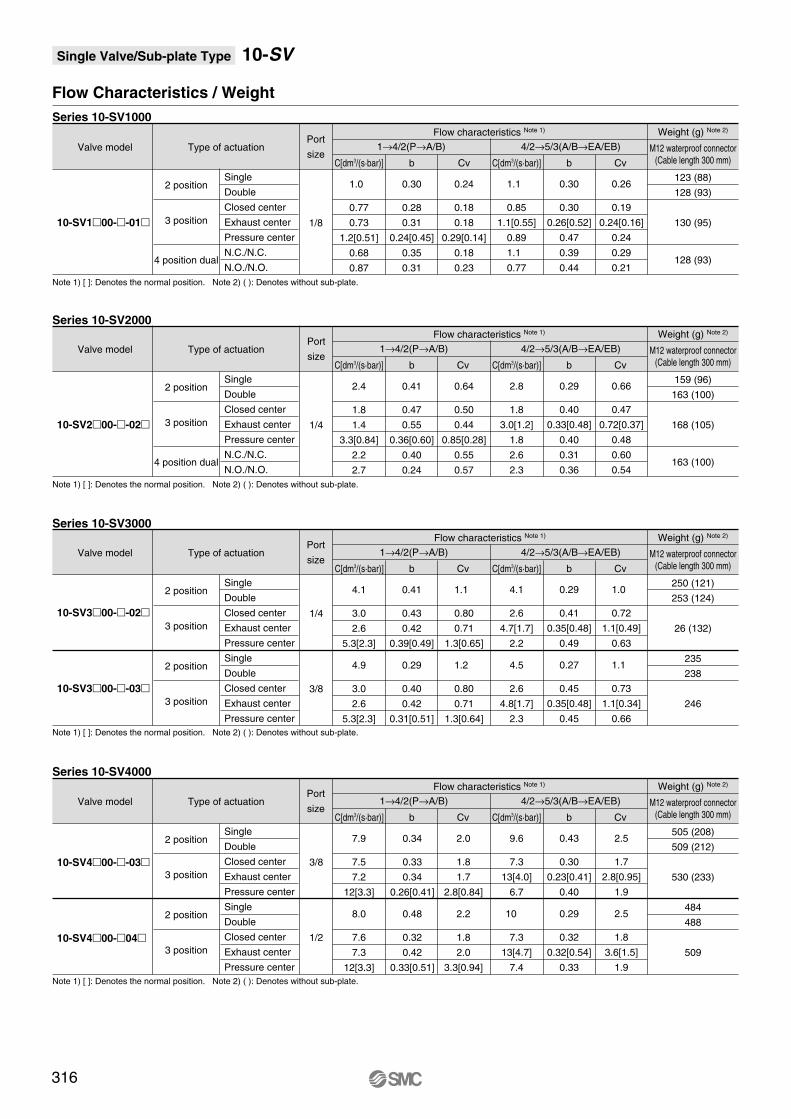
Flow Characteristics / Weight
Valve model Type of actuation
Flow characteristics Note 1)
1.0
0.77
0.73
1.2[0.51]
0.68
0.87
0.30
0.28
0.31
0.24[0.45]
0.35
0.31
0.24
0.18
0.18
0.29[0.14]
0.18
0.23
1.1
0.85
1.1[0.55]
0.89
1.1
0.77
0.30
0.30
0.26[0.52]
0.47
0.39
0.44
0.26
0.19
0.24[0.16]
0.24
0.29
0.21
1→4/2(P→A/B) 4/2→5/3(A/B→EA/EB)
Weight (g) Note 2)
123 (88)
128 (93)
130 (95)
128 (93)
M12 waterproof connector
(Cable length 300 mm)
Port
size
1/8
Single
Double
Closed center
Exhaust center
Pressure center
N.C./N.C.
N.O./N.O.
2 position
3 position
4 position dual
Note 1) [ ]: Denotes the normal position. Note 2) ( ): Denotes without sub-plate.
10-SV100--01
Series 10-SV1000
Series 10-SV2000
Series 10-SV3000
Series 10-SV4000
C[dm3/(s·bar)] b Cv C[dm3/(s·bar)] b Cv
Type of actuation
Flow characteristics Note 1)
2.4
1.8
1.4
3.3[0.84]
2.2
2.7
0.41
0.47
0.55
0.36[0.60]
0.40
0.24
0.64
0.50
0.44
0.85[0.28]
0.55
0.57
2.8
1.8
3.0[1.2]
1.8
2.6
2.3
0.29
0.40
0.33[0.48]
0.40
0.31
0.36
0.66
0.47
0.72[0.37]
0.48
0.60
0.54
1→4/2(P→A/B) 4/2→5/3(A/B→EA/EB)
Weight (g) Note 2)
159 (96)
163 (100)
168 (105)
163 (100)
M12 waterproof connector
(Cable length 300 mm)
Port
size
1/4
Single
Double
Closed center
Exhaust center
Pressure center
N.C./N.C.
N.O./N.O.
2 position
3 position
4 position dual
Note 1) [ ]: Denotes the normal position. Note 2) ( ): Denotes without sub-plate.
Valve model
10-SV200--02
C[dm3/(s·bar)] b Cv C[dm3/(s·bar)] b Cv
Type of actuation
Flow characteristics Note 1)
7.9
7.5
7.2
12[3.3]
8.0
7.6
7.3
12[3.3]
0.34
0.33
0.34
0.26[0.41]
0.48
0.32
0.42
0.33[0.51]
2.0
1.8
1.7
2.8[0.84]
2.2
1.8
2.0
3.3[0.94]
9.6
7.3
13[4.0]
6.7
10
7.3
13[4.7]
7.4
0.43
0.30
0.23[0.41]
0.40
0.29
0.32
0.32[0.54]
0.33
2.5
1.7
2.8[0.95]
1.9
2.5
1.8
3.6[1.5]
1.9
1→4/2(P→A/B) 4/2→5/3(A/B→EA/EB)
Weight (g) Note 2)
505 (208)
509 (212)
530 (233)
484
488
509
M12 waterproof connector
(Cable length 300 mm)
Port
size
3/8
1/2
Single
Double
Closed center
Exhaust center
Pressure center
Single
Double
Closed center
Exhaust center
Pressure center
2 position
3 position
2 position
3 position
Note 1) [ ]: Denotes the normal position. Note 2) ( ): Denotes without sub-plate.
Valve model
10-SV400--03
10-SV400-04
C[dm3/(s·bar)] b Cv C[dm3/(s·bar)] b Cv
Type of actuation
Flow characteristics Note 1)
4.1
3.0
2.6
5.3[2.3]
4.9
3.0
2.6
5.3[2.3]
0.41
0.43
0.42
0.39[0.49]
0.29
0.40
0.42
0.31[0.51]
1.1
0.80
0.71
1.3[0.65]
1.2
0.80
0.71
1.3[0.64]
4.1
2.6
4.7[1.7]
2.2
4.5
2.6
4.8[1.7]
2.3
0.29
0.41
0.35[0.48]
0.49
0.27
0.45
0.35[0.48]
0.45
1.0
0.72
1.1[0.49]
0.63
1.1
0.73
1.1[0.34]
0.66
1→4/2(P→A/B) 4/2→5/3(A/B→EA/EB)
Weight (g) Note 2)
250 (121)
253 (124)
26 (132)
235
238
246
M12 waterproof connector
(Cable length 300 mm)
Port
size
1/4
3/8
Single
Double
Closed center
Exhaust center
Pressure center
Single
Double
Closed center
Exhaust center
Pressure center
2 position
3 position
2 position
3 position
Note 1) [ ]: Denotes the normal position. Note 2) ( ): Denotes without sub-plate.
Valve model
10-SV300--02
10-SV300--03
C[dm3/(s·bar)] b Cv C[dm3/(s·bar)] b Cv
Single Valve/Sub-plate Type 10-SV
316

Air c
ylin
der
Rota
ry a
ctu
ato
rA
ir g
ripper
Directional contr
ol
valv
eF
ittings &
Tubin
gP
ressure
sw
itch
Cle
an g
as filt
er
Flo
w c
ontr
ol
equip
ment
Filt
er,
Pre
ssure
contr
ol equip
ment
Air p
repara
tion
equip
ment
Dimensions: Series 10-SV1000
2 position single/double, 4 position dual 3 port [M12 waterproof connector type]10-SV100(R)-W-01
3 position closed center / exhaust center / pressure center [M12 waterproof connector type]10-SV100(R)-W-01
SM
C
B
Manual override
A B
A
A side: Orange
B side: Green
(Light/surge voltage suppressor) M5 x 0.8
(Pilot EXH port) <In the case of external pilot type>
PE
(Piping port)
2-ø3.2(For mounting)
EBEA P
A B
M5 x 0.8
(External pilot port)
X
M12 waterproof connector
SM
C
B
Manual override
A B
A
A side: Orange
B side: Green
(Light/surge voltage suppressor) M5 x 0.8
(Pilot EXH port)<In the case of external pilot type>
PE
1/8
(Piping port)
2-ø3.2(For mounting)
EBEA P
A B
M5 x 0.8
(External pilot port)
X
M12 waterproof connector
43.3
54.1
11 11
20.5
14.5
13
.5
13.3
17
19
48
.5
53
.5
7.5
16
.5
24
.5
3
22
35 5.8
41 2.8
17
19
83.7
89.3(L = 300 to 5000)
11 11
20.5
14.5
13
.5
13.3
17
19
48
.5
53
.5
7.5
16
.5
24
.5
3
22
35
41
17
19
(L = 300 to 5000)
92.2
97.8
11.3
14.3
51.8
62.6
77
1/8
Single Valve / Sub-plate Type 10-SV
317

Dimensions: Series 10-SV2000
2 position single/double, 4 position dual 3 port [M12 waterproof connector type]10-SV200(R)-W-02
3 position closed center / exhaust center / pressure center [M12 waterproof connector type]10-SV200(R)-W-02
Manual override
A
B
SM
C
A B
A side: Orange
B side: Green
X
M5 x 0.8(External pilot port)
PE
(Light/surge voltage suppressor)
M5 x 0.8(Pilot EXH port)<In the case of external pilot type>
1/4
(Piping port)
A B
EA P EB
2-ø4.3
(For mounting)
Manual overrideA
B SM
C
A B
A side: Orange
B side: Green
X
M5 x 0.8
(External pilot port)
PE
(Light/surge voltage suppressor)
M5 x 0.8
(Pilot EXH port)<In the case of external pilot type>
1/4
(Piping port)
A B
EA P EB
2-ø4.3
(For mounting)
M12 waterproof connector
M12 waterproof connector
15.5
17
15.5
17
1818
28
9.5
22
51
(L = 300 to 5000)
18
9.5
19
56
35
48
4
15.5
17
15.5
17
1818
28
9.5
22
51
102.9
108.5(L = 300 to 5000)
18
9.5
19
56 5.3
35
48
61.1
73.3
9.3
4
115.5
121.1
17.9
73.7
85.9
21.9
4.5
4.5
Single Valve / Sub-plate Type 10-SV
318

Air c
ylin
der
Rota
ry a
ctu
ato
rA
ir g
ripper
Directional contr
ol
valv
eF
ittings &
Tubin
gP
ressure
sw
itch
Cle
an g
as filt
er
Flo
w c
ontr
ol
equip
ment
Filt
er,
Pre
ssure
contr
ol equip
ment
Air p
repara
tion
equip
ment
Single Valve / Sub-plate Type 10-SV
Dimensions: Series 10-SV3000
2 position single/double [M12 waterproof connector type]10-SV300(R)-W-02, 03
3 position closed center / exhaust center / pressure center [M12 waterproof connector type]10-SV300(R)-W-02, 03
Manual override
SM
C
B
A
A B
3/8,1/4
(Piping port)
X
M5 x 0.8
(External pilot port)
PE
M5 x 0.8
(Pilot EXH port)<In the case of external pilot type>
2-ø4.3
(For mounting)
EA EB
A B
P
A side: OrangeB side: Green
M12 waterproof connector
(Light/surge voltage suppressor)
A B
20.520.5
33 11
.5
13
.5 26
.5
58
.5
60
.3
(L = 300 to 5000)
115.8
121.4
2121.5
21
46
38
69 6.4
10.4
21.5
71.9
86.2
21 22.5
13
.5
61
Manual override
SM
C
B
A
A B
3/8,1/4(Piping port)
X
M5 x 0.8
(External pilot port)
PE
2-ø4.3(For mounting)
EA EB
A B
P
A side: OrangeB side: Green
M12 waterproof connector
(Light/surge voltage suppressor)
M5 x 0.8
(Pilot EXH port)<In the case of external pilot type>
A B
20.520.5
33
11
.5
13
.5 26
.5
58
.5
60
.3
(L = 300 to 5000)
128.8
134.4
2121.5
21
46
38
21.5
21 22.5
13
.5
6169 19.4
23.4
84.9
99.2
12
12
319
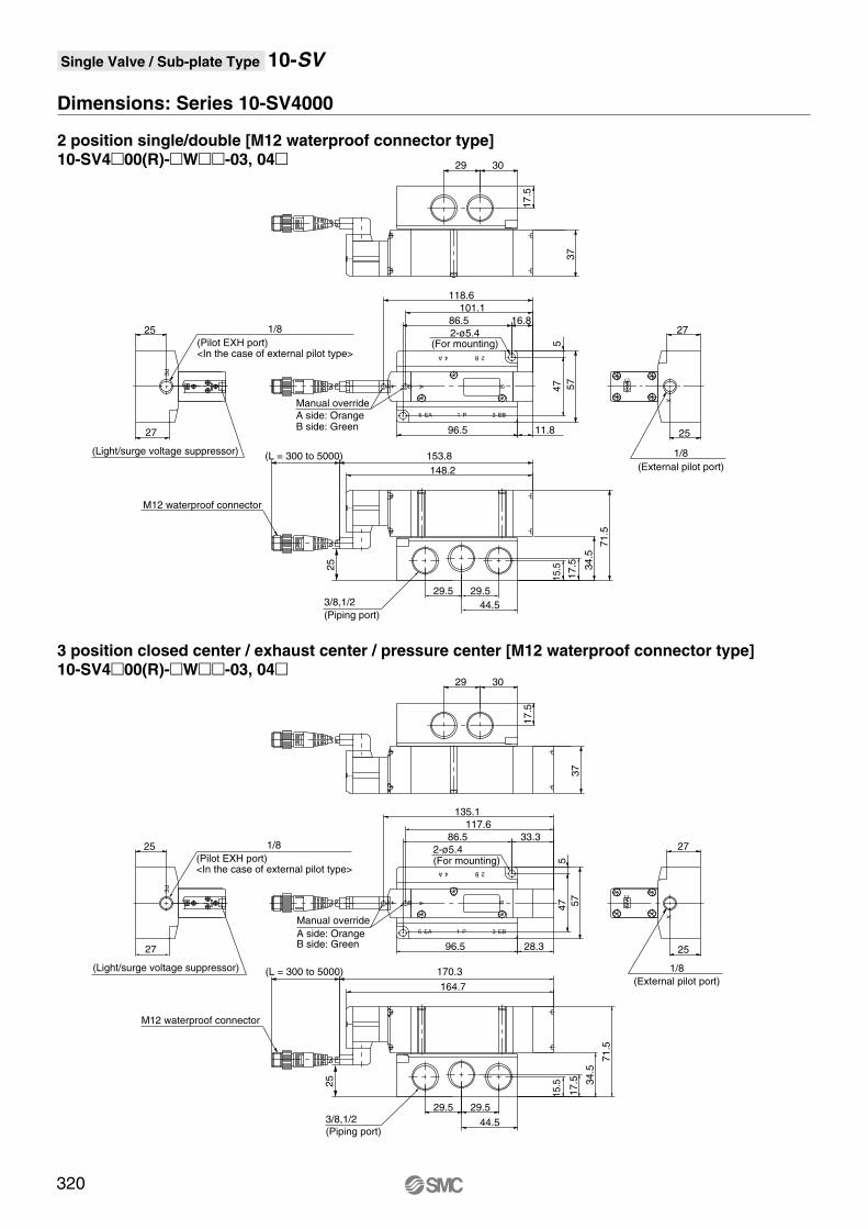
Single Valve / Sub-plate Type 10-SV
Dimensions: Series 10-SV4000
2 position single/double [M12 waterproof connector type]10-SV400(R)-W-03, 04
3 position closed center / exhaust center / pressure center [M12 waterproof connector type]10-SV400(R)-W-03, 04
B
A
SM
C
Manual override
A B
M12 waterproof connector
A side: OrangeB side: Green
X
1/8
(External pilot port)
PE
1/8
(Pilot EXH port)<In the case of external pilot type>
(Light/surge voltage suppressor)
5 EA 1 P 3 EB
B 2A 4
2-ø5.4(For mounting)
B
A
SM
C
Manual override
A B
M12 waterproof connector
A side: OrangeB side: Green
3/8,1/2
(Piping port)
X
1/8
(External pilot port)
PE
1/8
(Pilot EXH port)<In the case of external pilot type>
(Light/surge voltage suppressor)
5 EA 1 P 3 EB
B 2A 4
2-ø5.4(For mounting)
3/8,1/2
(Piping port)
37
(L = 300 to 5000)
29.5 29.5
44.5
15
.5
17
.5 34
.5
71
.5
148.2
153.8
27
25
25
27
54
7 57
11.8
101.1
118.6
86.5
96.5
16.8
29
17
.5
30
47
37
(L = 300 to 5000)
29.5 29.5
44.5
15
.5
17
.5 34
.5
71
.5
27
25
25
27
5
57
86.5
96.5
29
17
.5
30
164.7
170.3
28.3
33.3
117.6
135.1
25
25
320
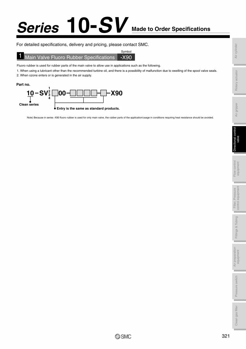
Air c
ylin
der
Rota
ry a
ctu
ato
rA
ir g
ripper
Directional contr
ol
valv
eF
ittings &
Tubin
gP
ressure
sw
itch
Cle
an g
as filt
er
Flo
w c
ontr
ol
equip
ment
Filt
er,
Pre
ssure
contr
ol equip
ment
Air p
repara
tion
equip
ment
Fluoro rubber is used for rubber parts of the main valve to allow use in applications such as the following.
1. When using a lubricant other than the recommended turbine oil, and there is a possibility of malfunction due to swelling of the spool valve seals.
2. When ozone enters or is generated in the air supply.
Note) Because in series -X90 fluoro rubber is used for only main valve, the rubber parts of the application/usage in conditions requiring heat resistance should be avoided.
1 Main Valve Fluoro Rubber Specifications -X90
Symbol
10 SV 00 X90
Entry is the same as standard products.
Clean series
Part no.1234
Series 10-SV Made to Order Specifications
For detailed specifications, delivery and pricing, please contact SMC.
321
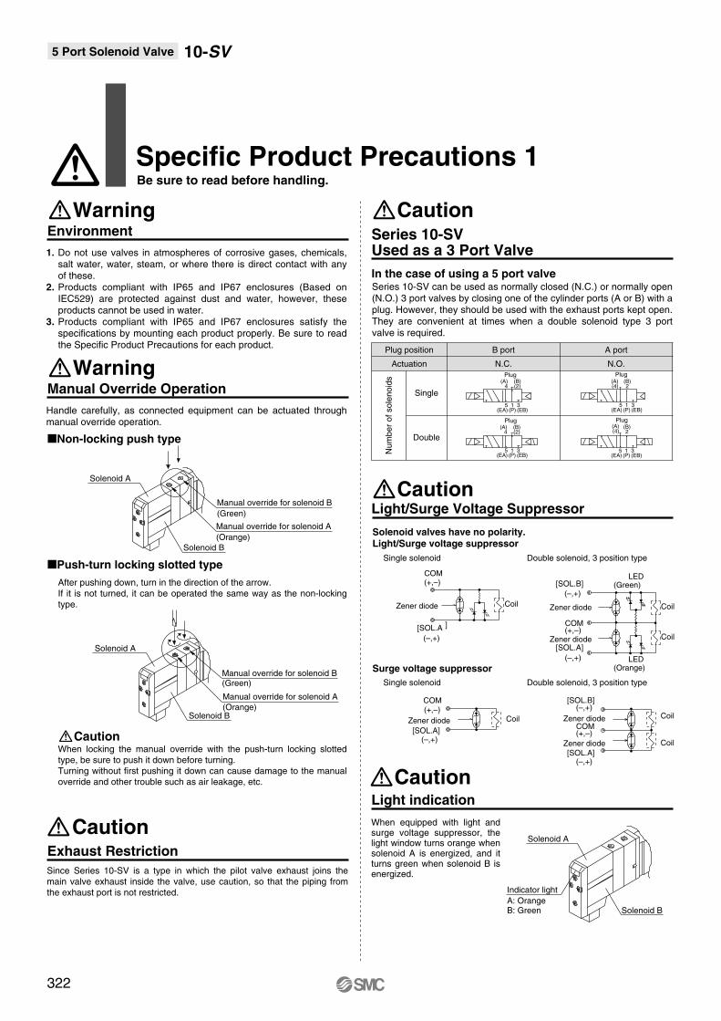
Manual Override Operation
Warning
Non-locking push type
Push-turn locking slotted type
Caution
Handle carefully, as connected equipment can be actuated through manual override operation.
After pushing down, turn in the direction of the arrow.
If it is not turned, it can be operated the same way as the non-locking
type.
When locking the manual override with the push-turn locking slotted
type, be sure to push it down before turning.
Turning without first pushing it down can cause damage to the manual
override and other trouble such as air leakage, etc.
Environment
Warning
1. Do not use valves in atmospheres of corrosive gases, chemicals, salt water, water, steam, or where there is direct contact with any of these.
2. Products compliant with IP65 and IP67 enclosures (Based on IEC529) are protected against dust and water, however, these products cannot be used in water.
3. Products compliant with IP65 and IP67 enclosures satisfy the specifications by mounting each product properly. Be sure to read the Specific Product Precautions for each product.
Light/Surge Voltage Suppressor
Caution
Solenoid valves have no polarity. Light/Surge voltage suppressor
Surge voltage suppressor
Light indication
Caution
When equipped with light and surge voltage suppressor, the light window turns orange when solenoid A is energized, and it turns green when solenoid B is energized. Since Series 10-SV is a type in which the pilot valve exhaust joins the
main valve exhaust inside the valve, use caution, so that the piping from
the exhaust port is not restricted.
Exhaust Restriction
Caution
Series 10-SV can be used as normally closed (N.C.) or normally open (N.O.) 3 port valves by closing one of the cylinder ports (A or B) with a plug. However, they should be used with the exhaust ports kept open. They are convenient at times when a double solenoid type 3 port valve is required.
Series 10-SVUsed as a 3 Port Valve
Caution
In the case of using a 5 port valve
Plug position
Actuation
Num
ber
of
sole
no
ids
Single
Double
A port
N.O.
5(EA)
1(P)
3(EB)
Plug
Plug Plug
5(EA)
1(P)
3(EB)
(A)4
(B)(2)
5(EA)
1(P)
3(EB)
(A)(4)
(B)2
5(EA)
1(P)
3(EB)
(A)(4)
(B)2
N.C.
Plug(A)
4(B)(2)
B port
Single solenoid Double solenoid, 3 position type
Single solenoid Double solenoid, 3 position type
[SOL.B](–,+)
[SOL.A](–,+)
COM(+,–)[SOL.A]
(–,+)
COM(+,–)
Zener diode Zener diode
Zener diode Coil
CoilCoil
Manual override for solenoid A
(Orange)
Solenoid B
Solenoid A
Manual override for solenoid B
(Green)
Solenoid A
Solenoid B
Manual override for solenoid A
(Orange)
Manual override for solenoid B(Green)
Solenoid B
Solenoid A
Indicator light
A: OrangeB: Green
[SOL.B]
(–,+)
[SOL.A]
(–,+)
COM(+,–)
][SOL.A
(–,+)
COM(+,–)
LED(Green)
LED(Orange)
Zener diode Coil
Coil
CoilZener diode
Zener diode
322
5 Port Solenoid Valve 10-SV
Specific Product Precautions 1Be sure to read before handling.

Air c
ylin
der
Rota
ry a
ctu
ato
rA
ir g
ripper
Directional contr
ol
valv
eF
ittings &
Tubin
gP
ressure
sw
itch
Cle
an g
as filt
er
Flo
w c
ontr
ol
equip
ment
Filt
er,
Pre
ssure
contr
ol equip
ment
Air p
repara
tion
equip
ment
CautionOne-touch Fittings
1. Tube attachment/detachment for One-touch fittings
1) Attaching of tube
(1) Take a tube having no flaws on its periphery and cut it off at a right
angle. When cutting the tube, use tube cutters TK-1, 2 or 3. Do not
use pinchers, nippers or scissors, etc. If cutting is done with tools
other than tube cutters, there is the danger that the tube may be
cut diagonally or become flattened, etc., making a secure
installation impossible, and causing problems such as the tube
pulling out after installation or air leakage.
Also allow some extra length in the tube.
(2) Grasp the tube and push it in slowly, inserting it securely all the
way into the fitting.
(3) After inserting the tube, pull on it lightly to confirm that it will not
come out. If it is not installed securely all the way into the fitting,
this can cause problems such as air leakage or the tube pulling
out.
2) Detaching of tube
(1) Push in the release button sufficiently, and push the collar evenly
at the same time.
(2) Pull out the tube while holding down the release button so that it
does not come out. If the release button is not pressed down
sufficiently, there will be increased bite on the tube and it will
become more difficult to pull it out.
(3) When the removed tube is to be used again, cut off the portion
which has been chewed before reusing it. If the chewed portion of
the tube is used as is, this can cause trouble such as air leakage
or difficulty in removing the tube.
Other Tubing Brands
Caution
1. When using tube other than SMC brand, confirm that the following
specifications are satisfied with respect to the outside diameter
tolerance of the tube.
1) Nylon tubing within +/– 0.1 mm
2) Soft nylon tubing within +/– 0.1 mm
3) Polyurethane tubing within +0.15 mm
within –0.2 mm
Do not use tubing which does not meet these outside diameter
tolerances. It may not be possible to connect them, or they may cause
other trouble, such as air leakage or the tube pulling out after connection.
Back Pressure Check Valve Built-in Type
Caution
Valves with built-in back pressure check valve is to protect the back
pressure inside a valve. For this reason, use caution the valves with
external pilot specification cannot be pressurized from exhaust port
[3/5(E)]. As compared with the types which do not integrate the back
pressure check valve, C value of the flow characteristics goes down. For
details, please contact SMC.
Lever
Substrate Assemblies inside Manifolds
Caution
Substrate assemblies inside of manifolds cannot be taken apart.
Attempting to do so may damage parts.
Connector Entry Directions
Caution
Connector entry directions for D-sub connectors and flat ribbon cables can
be changed. To change the connector's entry direction, press the levers on
both sides of the connector, take it off, and change the direction as shown
in the drawing. Since lead wire assemblies are attached to the connector,
excessive pulling or twisting can cause broken wires or other trouble. Also,
take precautions so that lead wires are not caught and pinched when
installing the connector.
How to Order Manifold
Caution
The letter "S" or "D" is indicated on manifold blocks for series 10-SV as
shown below. This indication refers to the type of substrate assembly
(single wiring or double wiring) inside the manifold blocks.
When the manifold specification sheet does not include a wiring
specification, all stations will be double wiring specification (D). In this
case, single and double solenoid valves can be mounted in any position,
but when a single valve is used, there will be an unused control signal. To
avoid this, indicate positions of manifold blocks for single wiring
specification (S) and double wiring specification (D) on a manifold
specification sheet. (Note that double, 3 or 4 position valves cannot be
used for manifolds blocks with single wiring specification (S).)
Lever
DD
SS
Wiring specifications symbol
DD
323
Specific Product Precautions 2Be sure to read before handling.
5 Port Solenoid Valve 10-SV
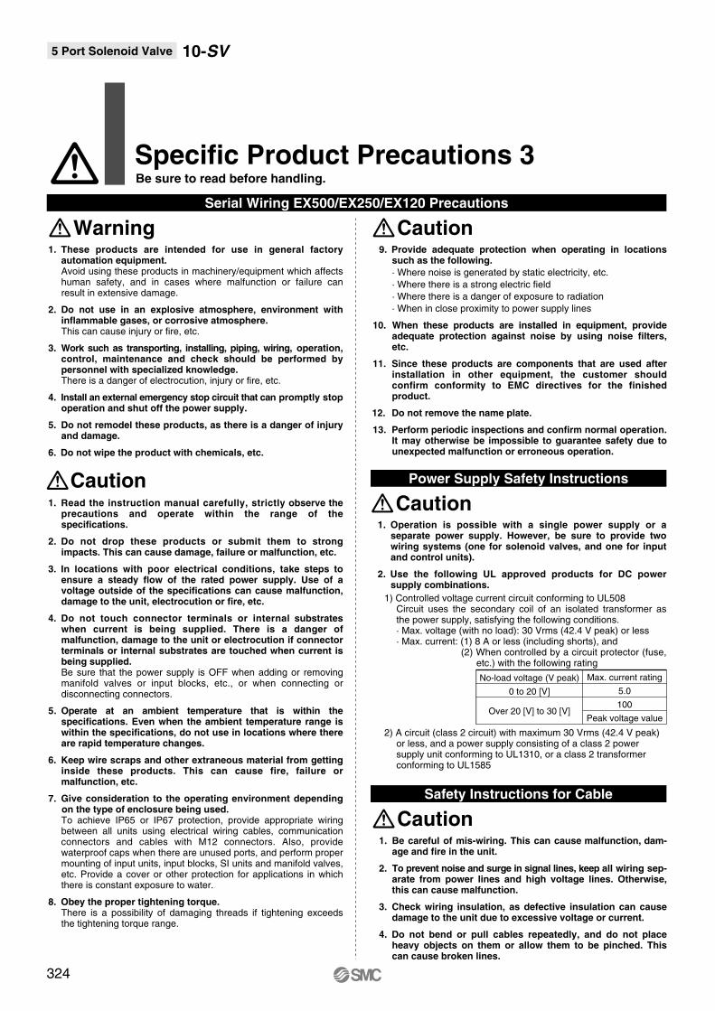
1. These products are intended for use in general factory automation equipment. Avoid using these products in machinery/equipment which affects human safety, and in cases where malfunction or failure can result in extensive damage.
2. Do not use in an explosive atmosphere, environment with inflammable gases, or corrosive atmosphere. This can cause injury or fire, etc.
3. Work such as transporting, installing, piping, wiring, operation, control, maintenance and check should be performed by personnel with specialized knowledge. There is a danger of electrocution, injury or fire, etc.
4. Install an external emergency stop circuit that can promptly stop operation and shut off the power supply.
5. Do not remodel these products, as there is a danger of injury and damage.
6. Do not wipe the product with chemicals, etc.
Caution1. Read the instruction manual carefully, strictly observe the
precautions and operate within the range of the specifications.
2. Do not drop these products or submit them to strong impacts. This can cause damage, failure or malfunction, etc.
3. In locations with poor electrical conditions, take steps to ensure a steady flow of the rated power supply. Use of a voltage outside of the specifications can cause malfunction, damage to the unit, electrocution or fire, etc.
4. Do not touch connector terminals or internal substrates when current is being supplied. There is a danger of malfunction, damage to the unit or electrocution if connector terminals or internal substrates are touched when current is being supplied.Be sure that the power supply is OFF when adding or removing manifold valves or input blocks, etc., or when connecting or disconnecting connectors.
5. Operate at an ambient temperature that is within the specifications. Even when the ambient temperature range is within the specifications, do not use in locations where there are rapid temperature changes.
6. Keep wire scraps and other extraneous material from getting inside these products. This can cause fire, failure or malfunction, etc.
7. Give consideration to the operating environment depending on the type of enclosure being used.
To achieve IP65 or IP67 protection, provide appropriate wiring between all units using electrical wiring cables, communication connectors and cables with M12 connectors. Also, provide waterproof caps when there are unused ports, and perform proper mounting of input units, input blocks, SI units and manifold valves, etc. Provide a cover or other protection for applications in which there is constant exposure to water.
8. Obey the proper tightening torque.There is a possibility of damaging threads if tightening exceeds the tightening torque range.
Serial Wiring EX500/EX250/EX120 Precautions
Warning9. Provide adequate protection when operating in locations
such as the following.
· Where noise is generated by static electricity, etc.
· Where there is a strong electric field
· Where there is a danger of exposure to radiation
· When in close proximity to power supply lines
10. When these products are installed in equipment, provide adequate protection against noise by using noise filters, etc.
11. Since these products are components that are used after installation in other equipment, the customer should confirm conformity to EMC directives for the finished product.
12. Do not remove the name plate.
13. Perform periodic inspections and confirm normal operation. It may otherwise be impossible to guarantee safety due to
unexpected malfunction or erroneous operation.
Caution
1. Be careful of mis-wiring. This can cause malfunction, dam-age and fire in the unit.
2. To prevent noise and surge in signal lines, keep all wiring sep-arate from power lines and high voltage lines. Otherwise, this can cause malfunction.
3. Check wiring insulation, as defective insulation can cause damage to the unit due to excessive voltage or current.
4. Do not bend or pull cables repeatedly, and do not place heavy objects on them or allow them to be pinched. This can cause broken lines.
Safety Instructions for Cable
Caution
No-load voltage (V peak)
0 to 20 [V]
Over 20 [V] to 30 [V]
Max. current rating
5.0
100
Peak voltage value
1. Operation is possible with a single power supply or a separate power supply. However, be sure to provide two wiring systems (one for solenoid valves, and one for input and control units).
2. Use the following UL approved products for DC power supply combinations.
1) Controlled voltage current circuit conforming to UL508Circuit uses the secondary coil of an isolated transformer as the power supply, satisfying the following conditions.· Max. voltage (with no load): 30 Vrms (42.4 V peak) or less· Max. current: (1) 8 A or less (including shorts), and
(2) When controlled by a circuit protector (fuse, etc.) with the following rating
2) A circuit (class 2 circuit) with maximum 30 Vrms (42.4 V peak) or less, and a power supply consisting of a class 2 power supply unit conforming to UL1310, or a class 2 transformer conforming to UL1585
Power Supply Safety Instructions
Caution
324
5 Port Solenoid Valve 10-SV
Specific Product Precautions 3Be sure to read before handling.