serial lcd controller - datarealmkitsrus.com/pdf/k192.pdf · k192 – serial lcd controller 2 1...
TRANSCRIPT

Serial LCD Controller DIY Electronics K192
User Guide
CONTENTS
1 INTRODUCTION. .........................................................................2
2 MODULE CONNECTION. ............................................................2
2.1 Serial RS232 interface connector. ...............................................................3
2.2 Serial TTL interface connector. ....................................................................3
2.3 Digital output connector. ..............................................................................3
2.4 Communication interface. ............................................................................3
2.5 Module connection example. .......................................................................4
3 COMMANDS. ...............................................................................5
3.1 Configuration Commands. ...........................................................................7
3.2 LCD Display Commands..............................................................................8
3.3 Bar Graphs and Custom Characters..........................................................10
3.4 Module control from Microsoft Visual Basic. ..............................................13
4 KIT ASSEMBLY..........................................................................13
Technical Support .................................................................................... 14
4.1 Parts List. ...................................................................................................14
4.2 PCB. ..........................................................................................................14
4.3 Module Schematic. ....................................................................................15

K192 – Serial LCD Controller
2
1 Introduction. This serial display module provides easy operation of a standard character LCD display. The simple command structure allows text and bar graphs to be displayed on the LCD. Provision is made for up to 8 user-defined characters. The module also includes four digital outputs. The LDC backlight and contrast may be adjusted under program control to compensate for differing lighting conditions and viewing angles. The module supports 2 interfaces:
• Serial RS232 interface • Serial TTL interface
The module has the following features:
• Communicates over serial interface with software controlled speed • 32 Byte buffer for messages received via communication interface • Up to 8 custom characters can be defined • Built in commands for drawing bar graphs • LCD Backlighting controlled via software, has 254 brightness levels • LCD Contrast controlled via software, has 254 contrast levels • 4 digital outputs • Save the basic settings in module internal EEPROM
NOTE: The supplied LCD does not have backlighting. User must supply a backlit LCD if this feature is required.
2 Module connection. The module has 5 connectors: LCD, Serial Port DB9 connector, Serial RS232 interface connector, Serial TTL interface connector and Digital output connector.
GND
OUTPUT 4
OUTPUT 3
OUTPUT 2
OUTPUT 1
RX TTL
GND
RX RS232
GND
+5V
+5V Serial Port DB9 Female connector
LCD Connector
K192 – Serial LCD Controller
3
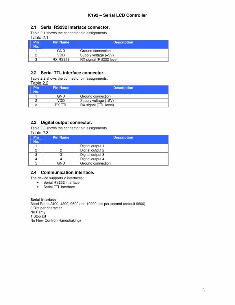
2.1 Serial RS232 interface connector.
Table 2.1 shows the connector pin assignments.
Table 2.1 Pin No.
Pin Name Description
1 GND Ground connection 2 VDD Supply voltage (+5V) 3 RX RS232 RX signal (RS232 level)
2.2 Serial TTL interface connector.
Table 2.2 shows the connector pin assignments.
Table 2.2 Pin No.
Pin Name Description
1 GND Ground connection 2 VDD Supply voltage (+5V) 3 RX TTL RX signal (TTL level)
2.3 Digital output connector.
Table 2.3 shows the connector pin assignments.
Table 2.3 Pin No.
Pin Name Description
1 1 Digital output 1 2 2 Digital output 2 3 3 Digital output 3 4 4 Digital output 4 5 GND Ground connection
2.4 Communication interface.
The device supports 2 interfaces: • Serial RS232 interface • Serial TTL interface
Serial Interface Baud Rates 2400, 4800, 9600 and 19200 bits per second (default 9600). 8 Bits per character No Parity 1 Stop Bit No Flow Control (Handshaking)
K192 – Serial LCD Controller
4
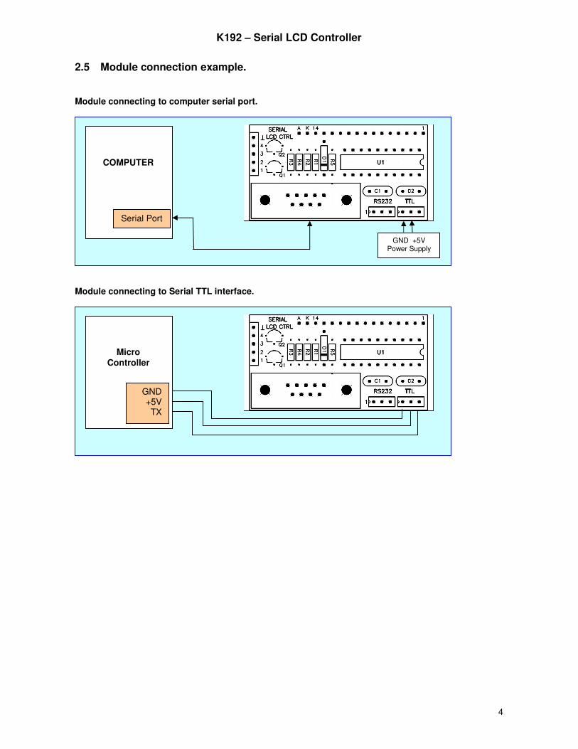
2.5 Module connection example.
Module connecting to computer serial port.
Module connecting to Serial TTL interface.
Micro Controller
GND +5V TX
COMPUTER
Serial Port
GND +5V Power Supply
K192 – Serial LCD Controller
5
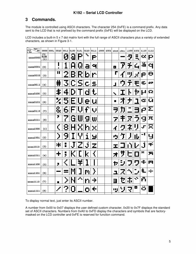
3 Commands. The module is controlled using ASCII characters. The character 254 (0xFE) is a command prefix. Any data sent to the LCD that is not prefixed by the command prefix (0xFE) will be displayed on the LCD. LCD includes a built-in 5 x 7 dot matrix font with the full range of ASCII characters plus a variety of extended characters, as shown in Figure 3-1.
To display normal text, just enter its ASCII number. A number from 0x00 to 0x07 displays the user defined custom character, 0x20 to 0x7F displays the standard set of ASCII characters. Numbers from 0xA0 to 0xFD display the characters and symbols that are factory-masked on the LCD controller and 0xFE is reserved for function command.

K192 – Serial LCD Controller
6
Command Summary Prefix Command Parameter Description 0xFE 0x02 1 byte Changing BAUD Rate
0xFE 0x03 1 byte Set Backlight Brightness
0xFE 0x04 1 byte Set Contrast 0xFE 0x06 None Display Firmware Version Number 0xFE 0x07 None Display Serial Baud Rate
0xFE 0x0A None Turn On Display
0xFE 0x0B None Turn Off Display
0xFE 0x0C 2 bytes Set Cursor Position
0xFE 0x0D None Home Cursor 0xFE 0x0E None Turn On Underline Cursor 0xFE 0x0F None Turn Off Underline Cursor 0xFE 0x10 None Move Cursor Left One Space
0xFE 0x11 None Move Cursor Right One Space
0xFE 0x12 None Turn On Blinking Cursor 0xFE 0x13 None Turn Off Blinking Cursor 0xFE 0x14 None Clear Screen
0xFE 0x15 Variable Print String
0xFE 0x16 1 byte Init Horizontal Bar Graph
0xFE 0x17 4 bytes Draw Horizontal Bar Graph
0xFE 0x18 None Init Vertical Bar Graph
0xFE 0x19 4 bytes Draw Vertical Bar Graph
0xFE 0x1A 9 bytes Load Custom Characters
0xFE 0x1E 1 byte Write to Digital Outputs
K192 – Serial LCD Controller
7
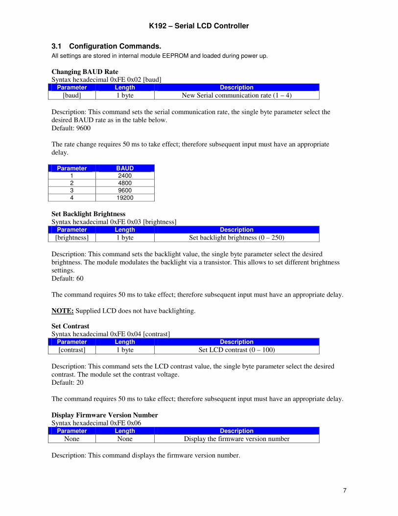
3.1 Configuration Commands.
All settings are stored in internal module EEPROM and loaded during power up.
Changing BAUD Rate Syntax hexadecimal 0xFE 0x02 [baud]
Parameter Length Description
[baud] 1 byte New Serial communication rate (1 – 4)
Description: This command sets the serial communication rate, the single byte parameter select the
desired BAUD rate as in the table below.
Default: 9600
The rate change requires 50 ms to take effect; therefore subsequent input must have an appropriate
delay.
Parameter BAUD
1 2400 2 4800 3 9600 4 19200
Set Backlight Brightness Syntax hexadecimal 0xFE 0x03 [brightness]
Parameter Length Description
[brightness] 1 byte Set backlight brightness (0 – 250)
Description: This command sets the backlight value, the single byte parameter select the desired
brightness. The module modulates the backlight via a transistor. This allows to set different brightness
settings.
Default: 60
The command requires 50 ms to take effect; therefore subsequent input must have an appropriate delay.
NOTE: Supplied LCD does not have backlighting.
Set Contrast Syntax hexadecimal 0xFE 0x04 [contrast]
Parameter Length Description
[contrast] 1 byte Set LCD contrast (0 – 100)
Description: This command sets the LCD contrast value, the single byte parameter select the desired
contrast. The module set the contrast voltage.
Default: 20
The command requires 50 ms to take effect; therefore subsequent input must have an appropriate delay.
Display Firmware Version Number Syntax hexadecimal 0xFE 0x06
Parameter Length Description
None None Display the firmware version number
Description: This command displays the firmware version number.
K192 – Serial LCD Controller
8
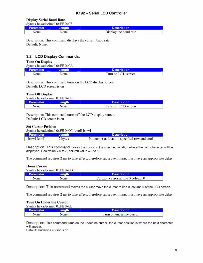
Display Serial Baud Rate
Syntax hexadecimal 0xFE 0x07 Parameter Length Description
None None Display the baud rate
Description: This command displays the current baud rate.
Default: None.
3.2 LCD Display Commands.
Turn On Display Syntax hexadecimal 0xFE 0x0A
Parameter Length Description
None None Turn on LCD screen
Description: This command turns on the LCD display screen.
Default: LCD screen is on
Turn Off Display Syntax hexadecimal 0xFE 0x0B
Parameter Length Description
None None Turn off LCD screen
Description: This command turns off the LCD display screen.
Default: LCD screen is on
Set Cursor Position Syntax hexadecimal 0xFE 0x0C [cool] [row]
Parameter Length Description
[row] [cool] 2 bytes Put cursor at location specified row and cool
Description: This command moves the cursor to the specified location where the next character will be displayed. Row value = 0 to 3, column value = 0 to 19.
The command requires 2 ms to take effect; therefore subsequent input must have an appropriate delay.
Home Cursor Syntax hexadecimal 0xFE 0x0D
Parameter Length Description
None None Position cursor at line 0 column 0
Description: This command moves the cursor move the cursor to line 0, column 0 of the LCD screen.
The command requires 2 ms to take effect; therefore subsequent input must have an appropriate delay.
Turn On Underline Cursor Syntax hexadecimal 0xFE 0x0E
Parameter Length Description
None None Turn on underline cursor
Description: This command turns on the underline cursor, the cursor position is where the next character will appear. Default: Underline cursor is off.
K192 – Serial LCD Controller
9
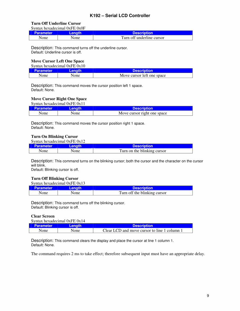
Turn Off Underline Cursor
Syntax hexadecimal 0xFE 0x0F Parameter Length Description
None None Turn off underline cursor
Description: This command turns off the underline cursor. Default: Underline cursor is off.
Move Cursor Left One Space
Syntax hexadecimal 0xFE 0x10 Parameter Length Description
None None Move cursor left one space
Description: This command moves the cursor position left 1 space. Default: None.
Move Cursor Right One Space
Syntax hexadecimal 0xFE 0x11 Parameter Length Description
None None Move cursor right one space
Description: This command moves the cursor position right 1 space. Default: None.
Turn On Blinking Cursor
Syntax hexadecimal 0xFE 0x12 Parameter Length Description
None None Turn on the blinking cursor
Description: This command turns on the blinking cursor; both the cursor and the character on the cursor will blink. Default: Blinking cursor is off.
Turn Off Blinking Cursor Syntax hexadecimal 0xFE 0x13
Parameter Length Description
None None Turn off the blinking cursor
Description: This command turns off the blinking cursor. Default: Blinking cursor is off.
Clear Screen Syntax hexadecimal 0xFE 0x14
Parameter Length Description
None None Clear LCD and move cursor to line 1 column 1
Description: This command clears the display and place the cursor at line 1 column 1. Default: None.
The command requires 2 ms to take effect; therefore subsequent input must have an appropriate delay.
K192 – Serial LCD Controller
10
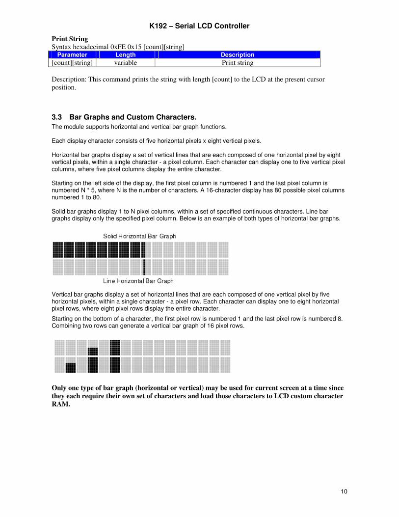
Print String
Syntax hexadecimal 0xFE 0x15 [count][string] Parameter Length Description
[count][string] variable Print string
Description: This command prints the string with length [count] to the LCD at the present cursor
position.
3.3 Bar Graphs and Custom Characters.
The module supports horizontal and vertical bar graph functions. Each display character consists of five horizontal pixels x eight vertical pixels. Horizontal bar graphs display a set of vertical lines that are each composed of one horizontal pixel by eight vertical pixels, within a single character - a pixel column. Each character can display one to five vertical pixel columns, where five pixel columns display the entire character. Starting on the left side of the display, the first pixel column is numbered 1 and the last pixel column is numbered N * 5, where N is the number of characters. A 16-character display has 80 possible pixel columns numbered 1 to 80. Solid bar graphs display 1 to N pixel columns, within a set of specified continuous characters. Line bar graphs display only the specified pixel column. Below is an example of both types of horizontal bar graphs.
Vertical bar graphs display a set of horizontal lines that are each composed of one vertical pixel by five horizontal pixels, within a single character - a pixel row. Each character can display one to eight horizontal pixel rows, where eight pixel rows display the entire character.
Starting on the bottom of a character, the first pixel row is numbered 1 and the last pixel row is numbered 8. Combining two rows can generate a vertical bar graph of 16 pixel rows.
Only one type of bar graph (horizontal or vertical) may be used for current screen at a time since
they each require their own set of characters and load those characters to LCD custom character
RAM.
K192 – Serial LCD Controller
11
Init Horizontal Bar Graph
Syntax hexadecimal 0xFE 0x16 [type] Parameter Length Description
[type] 1 byte Init horizontal bar graph
0 = solid graph, 1 = line graph
Description: Initializes the LCD to display the specified type of horizontal bar graph. This function should be called prior to calling Draw Horizontal Bar Graph. The type of bar graph must be specified. This function does not draw a bar graph, but loads the custom character RAM with the data required to display the specified type of bar graph. This routine must be called to change between horizontal bar-graph types.
The command requires 2 ms to take effect; therefore, the subsequent input must have an appropriate
delay.
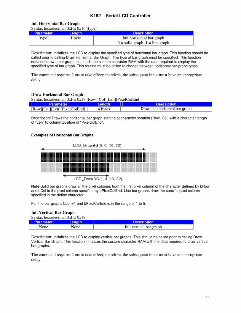
Draw Horizontal Bar Graph Syntax hexadecimal 0xFE 0x17 [Row][Col][Len][PixelColEnd]
Parameter Length Description
[Row][Col][Len][PixelColEnd] 4 bytes Draws the horizontal bar graph
Description: Draws the horizontal bar graph starting at character location (Row, Col) with a character length of "Len" to column position of "PixelColEnd". Examples of Horizontal Bar Graphs
Note Solid bar graphs draw all the pixel columns from the first pixel column of the character defined by bRow and bCol to the pixel column specified by bPixelColEnd. Line bar graphs draw the specific pixel column specified in the define character. For line bar graphs bLen=1 and bPixelColEnd is in the range of 1 to 5.
Init Vertical Bar Graph
Syntax hexadecimal 0xFE 0x18 Parameter Length Description
None None Init vertical bar graph
Description: Initializes the LCD to display vertical bar graphs. This should be called prior to calling Draw Vertical Bar Graph. This function initializes the custom character RAM with the data required to draw vertical bar graphs.
The command requires 2 ms to take effect; therefore, the subsequent input must have an appropriate
delay.
K192 – Serial LCD Controller
12
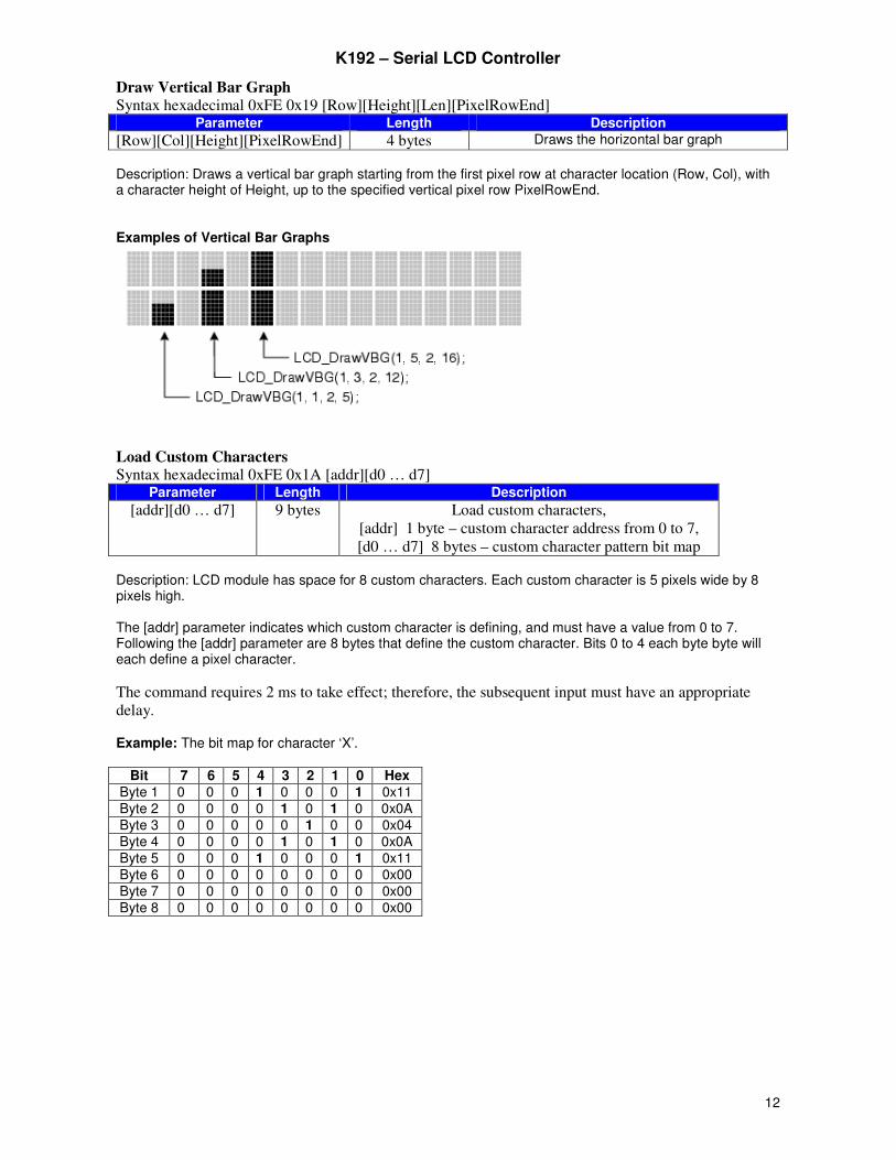
Draw Vertical Bar Graph
Syntax hexadecimal 0xFE 0x19 [Row][Height][Len][PixelRowEnd] Parameter Length Description
[Row][Col][Height][PixelRowEnd] 4 bytes Draws the horizontal bar graph
Description: Draws a vertical bar graph starting from the first pixel row at character location (Row, Col), with a character height of Height, up to the specified vertical pixel row PixelRowEnd. Examples of Vertical Bar Graphs
Load Custom Characters Syntax hexadecimal 0xFE 0x1A [addr][d0 … d7]
Parameter Length Description
[addr][d0 … d7] 9 bytes Load custom characters,
[addr] 1 byte – custom character address from 0 to 7,
[d0 … d7] 8 bytes – custom character pattern bit map Description: LCD module has space for 8 custom characters. Each custom character is 5 pixels wide by 8 pixels high. The [addr] parameter indicates which custom character is defining, and must have a value from 0 to 7. Following the [addr] parameter are 8 bytes that define the custom character. Bits 0 to 4 each byte byte will each define a pixel character.
The command requires 2 ms to take effect; therefore, the subsequent input must have an appropriate
delay. Example: The bit map for character ‘X’.
Bit 7 6 5 4 3 2 1 0 Hex Byte 1 0 0 0 1 0 0 0 1 0x11 Byte 2 0 0 0 0 1 0 1 0 0x0A Byte 3 0 0 0 0 0 1 0 0 0x04 Byte 4 0 0 0 0 1 0 1 0 0x0A Byte 5 0 0 0 1 0 0 0 1 0x11 Byte 6 0 0 0 0 0 0 0 0 0x00 Byte 7 0 0 0 0 0 0 0 0 0x00 Byte 8 0 0 0 0 0 0 0 0 0x00
K192 – Serial LCD Controller
13
Write to Digital Outputs
Syntax hexadecimal 0xFE 0x1E [Data] Parameter Length Description [Data] 1 byte Write to digital outputs
Description: This command writes 1 data byte to 4 digital outputs.
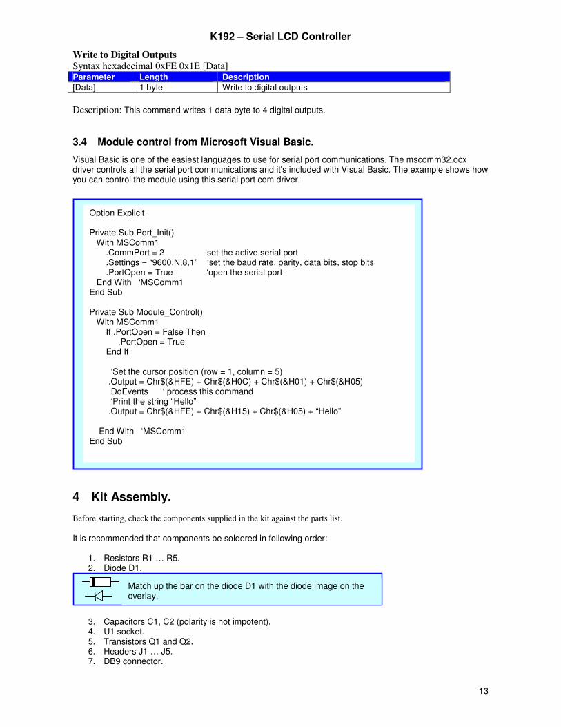
3.4 Module control from Microsoft Visual Basic.
Visual Basic is one of the easiest languages to use for serial port communications. The mscomm32.ocx driver controls all the serial port communications and it's included with Visual Basic. The example shows how you can control the module using this serial port com driver.
4 Kit Assembly. Before starting, check the components supplied in the kit against the parts list.
It is recommended that components be soldered in following order:
1. Resistors R1 … R5. 2. Diode D1.
3. Capacitors C1, C2 (polarity is not impotent). 4. U1 socket. 5. Transistors Q1 and Q2. 6. Headers J1 … J5. 7. DB9 connector.
Match up the bar on the diode D1 with the diode image on the overlay.
Option Explicit Private Sub Port_Init() With MSComm1 .CommPort = 2 ‘set the active serial port .Settings = “9600,N,8,1” ‘set the baud rate, parity, data bits, stop bits .PortOpen = True ‘open the serial port End With ‘MSComm1 End Sub Private Sub Module_Control() With MSComm1 If .PortOpen = False Then .PortOpen = True End If ‘Set the cursor position (row = 1, column = 5) .Output = Chr$(&HFE) + Chr$(&H0C) + Chr$(&H01) + Chr$(&H05) DoEvents ‘ process this command ‘Print the string “Hello” .Output = Chr$(&HFE) + Chr$(&H15) + Chr$(&H05) + “Hello” End With ‘MSComm1 End Sub
K192 – Serial LCD Controller
14
Pre-test. Do not insert the microcontroller chip into socket yet and do not connect the LCD module to serial controller. Connect a 5VDC supply to J4 header and measure the voltage across pin 10 (ground) and pin 20 (+5V) of the socket U1. If this voltage is approximately 5 volts, remove power, insert the microcontroller chip U1 and connect the serial controller to LCD module.
Technical Support. Contact the kit developer by email to ‘[email protected]’
4.1 Parts List.
Ref Des Qty Type
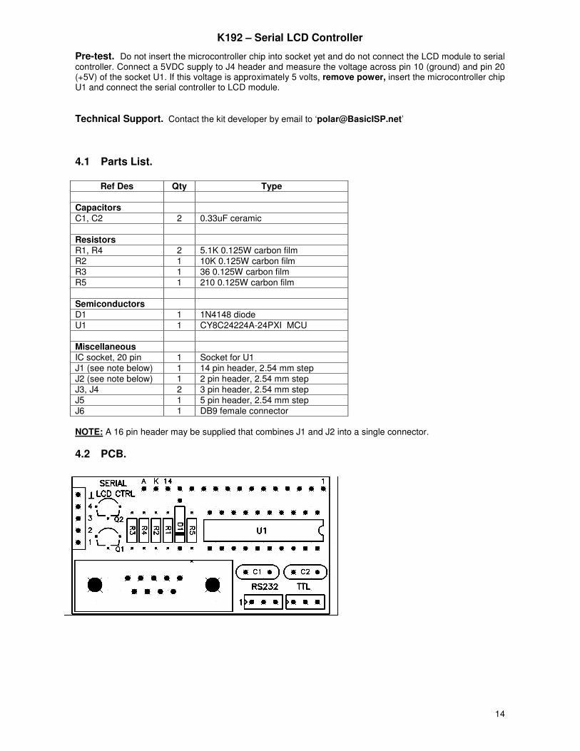
Capacitors C1, C2 2 0.33uF ceramic Resistors R1, R4 2 5.1K 0.125W carbon film R2 1 10K 0.125W carbon film R3 1 36 0.125W carbon film R5 1 210 0.125W carbon film Semiconductors D1 1 1N4148 diode U1 1 CY8C24224A-24PXI MCU Miscellaneous IC socket, 20 pin 1 Socket for U1 J1 (see note below) 1 14 pin header, 2.54 mm step J2 (see note below) 1 2 pin header, 2.54 mm step J3, J4 2 3 pin header, 2.54 mm step J5 1 5 pin header, 2.54 mm step J6 1 DB9 female connector NOTE: A 16 pin header may be supplied that combines J1 and J2 into a single connector.
4.2 PCB.
K192 – Serial LCD Controller
15
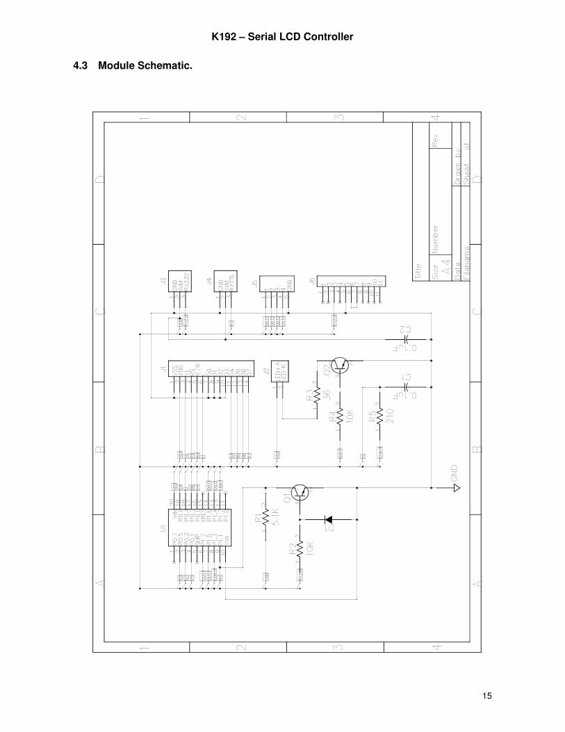
4.3 Module Schematic.