september 2005 – volume 34 issue 3 - sigmod record · september 2005 – volume 34 ... m....
TRANSCRIPT

[Editor’s note: With the exception of the last pages –which would be the back cover of the printed issue– that are not
included in this file, it has the same contents as the printed edition. All the articles are also available individually
online and have been put together here for convenience only.]
SIGMOD OFFICERS, COMMITTEES AND AWARDS ...................................................................... 1 EDITOR'S NOTES................................................................................................................................. 2 SPECIAL SECTION ON SCIENTIFIC WORKFLOWS
Guest Editors’ Introduction to the Special Section on Scientific Workflows ............................... 3 B. Ludaescher and C.Goble
Integrating Databases and Workflow Systems ............................................................................. 5 S. Shankar, A. Kini, D.J. DeWitt and J. Naughton
An Approach for Pipelining Nested Collections in Scientific Workflows ................................... 12 T.M. McPhillips and S. Bowers WOODSS and the Web: Annotating and Reusing Scientific Workflows................................... 18
C. B. Medeiros, J. Perez-Alcazar, L. Digiampietri, G. Z. Pastorello Jr, A. Santanche, R. S. Torres, E. Madeira and E. Bacarin
Simplifying Construction of Complex Workflows for Non-Expert Users of the Southern California Earthquake Center Community Modeling Environment............................................ 24
P. Maechling, H. Chalupsky, M. Dougherty, E. Deelman, Y. Gil, S. Gullapalli, V. Gupta, C. Kesselman, J. Kim, G. Mehta, B. Mendenhall, T. Russ, G. Singh, M. Spraragen, G. Staples, K. Vahi
A Survey of Data Provenance in e-Science................................................................................ 31 Y.L. Simmhan, B. Plale and D. Gannon
A Notation and System for Expressing and Executing Cleanly Typed Workflows on Messy Scientific Data ................................................................................................................... 37 Yong Zhao, J. Dobson, I. Foster, L. Moreau and M. Wilde A Taxonomy of Scientific Workflow Systems for Grid Computing............................................. 44 J. Yu and R. Buyya XML Database Support for Distributed Execution of Data-intensive Scientific Workflows ...................................................................................................................................... 50
S. Hastings, M. Ribeiro, S. Langella, S. Oster, U. Catalyurek, T. Pan, K. Huang, R. Ferreira, J. Saltz and T. Kurc
Scheduling of Scientific Workflows in the ASKALON Grid Environment .................................. 56 M. Wieczorek, R. Prodan and T. Fahringer
REGULAR RESEARCH ARTICLES Efficient Calendar Based Temporal Association Rule................................................................ 63
K. Verma and O. P. Vyas Artemis Message Exchange Framework: Semantic Interoperability of Exchanged Messages in the Healthcare Domain........................................................................................... 71
V. Bicer, G.B. Laleci, A. Dogac and Y. Kabak RESEARCH CENTERS (U. Centitemel, editor)
Database Research at Bilkent University .................................................................................... 77 O. Ulusoy
Data Management Research at the Middle East Technical University ..................................... 81 N. Cicekli, A. Cosar, A. Dogac, F. Polat, P. Senkul, I. Toroslu and A. Yazici
EVENT REPORTS (B. Cooper, editor) Report on the Workshop on Wrapper Techniques for Legacy Data Systems......................... 85
Ph. Thiran, T. Risch, C. Costilla, J. Henrard, Th. Kabisch, J. Petrini, W-J. van den Heuvel and J-L. Hainaut
Exchange, Integration and Consistency of Data. Report on the ARISE/NISR Workshop....... 87 L. Bertossi, J. Chomicki, P. Godfrey, P.G. Kolaitis, A. Thomo, and C. Zuzarte
DATABASE PRINCIPLES (L. Libkin, editor) Query Answering Exploiting Structural Properties...................................................................... 91
F. Scarcello DISTINGUISHED DATABASE PROFILES (M. Winslett, editor)
John Wilkes Speaks Out ............................................................................................................100 REMINISCENCES ON INFLUENTIAL PAPERS (K. A. Ross, editor) ...........................................111 TODS REPORT (R. Snodgrass, editor) ...........................................................................................114
SIG
MO
D R
ecord
–
Sep
tem
ber 2
00
5
–
Vo
lum
e 3
4
Issu
e 3
–
id
/d

SIGMOD Officers, Committees, and Awardees Chair Vice-Chair Secretary/Treasurer
Raghu Ramakrishnan Department of Computer Sciences University of Wisconsin-Madison 1210 West Dayton Street Madison, WI 53706-1685
Yannis Ioannidis University Of Athens
Department of Informatics & Telecom
Panepistimioupolis, Informatics Bldngs
157 84 Ilissia, Athens
HELLAS [email protected]
Mary Fernández ATT Labs - Research 180 Park Ave., Bldg 103, E277 Florham Park, NJ 07932-0971 USA [email protected]
Information Director: Alexandros Labrinidis, University of Pittsburgh, [email protected].
Associate Information Directors: Manfred Jeusfeld, Dongwon Lee, Michael Ley, Frank Neven, Altigran
Soares da Silva, Jun Yang.
Advisory Board: Richard Snodgrass (Chair), University of Arizona, [email protected], H.V. Jagadish,
John Mylopoulos, David DeWitt, Jim Gray, Hank Korth, Mike Franklin, Patrick Valduriez, Timos Sellis, S.
Sudarshan.
SIGMOD Conference Coordinator: Jianwen Su, UC Santa Barbara, [email protected]
SIGMOD Workshops Coordinator: Laurent Amsaleg, IRISA Lab, [email protected]
Industrial Advisory Board: Daniel Barbará (Chair), George Mason Univ., [email protected], José
Blakeley, Paul G. Brown, Umeshwar Dayal, Mark Graves, Ashish Gupta, Hank Korth, Nelson M. Mattos,
Marie-Anne Neimat, Douglas Voss.
SIGMOD Record Editorial Board: Mario A. Nascimento (Editor), University of Alberta,
[email protected], José Blakeley, Ugur Cetintemel, Brian Cooper, Andrew Eisenberg, Leonid Libkin,
Alexandros Labrinidis, Jim Melton, Len Seligman, Jignesh Patel, Ken Ross, Marianne Winslett.
SIGMOD Anthology Editorial Board: Curtis Dyreson (Editor), Washington State University,
[email protected], Nick Kline, Joseph Albert, Stefano Ceri, David Lomet.
SIGMOD DiSC Editorial Board: Shahram Ghandeharizadeh (Editor), USC, [email protected],
A. Ailamaki, W. Aref, V. Atluri, R. Barga, K. Boehm, K.S. Candan, Z. Chen, B. Cooper, J. Eder, V. Ganti, J.
Goldstein, G. Golovchinsky, Z. Ives, H-A. Jacobsen, V. Kalogeraki, S.H. Kim, L.V.S. Lakshmanan, D.
Lopresti, M. Mattoso, S. Mehrotra, R. Miller, B. Moon, V. Oria, G. Ozsoyoglu, J. Pei, A. Picariello, F. Sadri, J.
Shanmugasundaram, J. Srivastava, K. Tanaka, W. Tavanapong, V. Tsotras, M. Zaki, R. Zimmermann.
SIGMOD Digital Review Editorial Board: H. V. Jagadish (Editor), Univ. of Michigan,
[email protected], Alon Halevy, Michael Ley, Yannis Papakonstantinou, Nandit Soparkar.
Sister Society Liaisons: Stefano Ceri (VLDB Foundation and EDBT Endowment), Hongjun Lu (SIGKDD and
CCFDBS), Yannis Ioannidis (IEEE TCDE), Serge Abiteboul (PODS and ICDT Council).
Latin American Liaison Commitee: Claudia M. Bauzer Medeiros (Chair), University of Campinas,
[email protected] Alfonso Aguirre, Leopoldo Bertossi, Alberto Laender, Sergio Lifschitz, Marta
Mattoso, Gustavo Rossi.
Awards Committee: Moshe Y. Vardi (Chair), Rice University, [email protected]. Rudolf Bayer,
Masaru Kitsuregawa, Z. Meral Ozsoyoglu, Pat Selinger, Michael Stonebraker.
Award Recipients:
Innovation Award: Michael Stonebraker, Jim Gray, Philip Bernstein, David DeWitt, C. Mohan, David Maier,
Serge Abiteboul, Hector Garcia-Molina, Rakesh Agrawal, Rudolf Bayer, Patricia Selinger, Don Chamberlin,
Ronald Fagin.
Contributions Award: Maria Zemankova, Gio Wiederhold, Yahiko Kambayashi, Jeffrey Ullman, Avi
Silberschatz, Won Kim, Raghu Ramakrishnan, Laura Haas, Michael Carey, Daniel Rosenkrantz, Richard
Snodgrass, Michael Ley, Surajit Chaudhuri.
SIGMOD Record, Vol. 34, No. 3, Sept. 2005 1

Editor’s Notes
Dear Colleagues,
This is the first issue with the newly elected officers for SIGMOD: Raghu Ramakrishnan (Chair), Yannis
Ioannidis (Vice-chair) and Mary Fernández (Secretary/Treasurer). I am confident I can speak for all
members when I bid a warm welcome and wish them a productive mandate. Likewise, I would also like
to thank the other candidates, Ahmed Elmagarmid, Krithi Ramamritham and Louiqa Rashid, for putting
forward their names. As others have mentioned it before, is good to see that SIGMOD can count on
good people willing to keep its well-established tradition.
You will probably notice that this issue is missing the traditional Chair’s Message. The reason for that is
simple: timing. Even though this is September’s issue, it is closed and sent to ACM’s Headquarters late
in July. Raghu took over shortly before I had to close this issue, and amid all the transition work, his
message could not be prepared in time; hence this issue will not feature the Chair’s Message. However,
in a quick email exchange he asked me to relay the following message: “I’m glad to have the opportunity
to be chair and to work with Mary and Yannis, and we're working to understand the issues involved in
our new offices.” We all look forward for his first message in December’s issue. The new officers are
also in the process of updating the volunteer committees as well, so the listing you see on this issue is
likely to change for the next ones.
This issue features a special section on Scientific Workflows guest-edited by Bertram Ludäscher (Univ.
of California, Davis) and Carole Goble (Univ. of Manchester). As you can see from their introduction to
the special section, they were able to put good together a good set of papers covering several aspects of
this new area. I hope to be able to have similar guest-edited special section once or twice a year. If you
have an idea about one and are willing to work on it, please contact me.
On a sad note, Alberto Mendelzon passed away last June. I think that the following, excerpted from a
statement1 by his colleagues in the Toronto Database Group, summarizes everyone’s feelings well:
“Alberto was a great intellect, a charming friend, and an inspirational mentor. The citation for his recent
election into the Royal Society of Canada (the Canadian National Academy) gives a glimpse into his
intellectual legacy, but says nothing of the great man who will be sorely missed. His passing leaves a
hole in our community and in our hearts.” As I type this note, his colleagues in Toronto are working on
a tribute that should appear in December’s issue.
Finally, the Record does have a backlog of papers both to be printed and to be reviewed. While it is nice
to have a larger number of papers being submitted, this puts further stress on the reviewing process
(which I mentioned on June’s issue). I assure you that all submitted papers are given fair attention,
which, sometimes, means a longer review time. As well, all those accepted will be published as soon as
possible. I wish all could be published as they are accepted, but I have to work within a pre-determined
page budget, which means all papers have to wait for its turn “in line”. I am sure you all understand
(though I also understand you may not like it when it is your paper that is delayed, but c’est la vie).
I hope you enjoy this issue and that you have had a good Summer time (or Winter time depending on
which hemisphere you are).
Mario Nascimento, Editor.
July 2005
1 http://www.sigmod.org/NEWS/05/alberto.16june2005.html
2 SIGMOD Record, Vol. 34, No. 3, Sept. 2005

Guest Editors’ Introduction to the Special Section onScientific Workflows
Bertram LudascherDept. of Computer Science & Genome Center
University of California, Davis1 Shields Ave, Davis, CA 95616, USA
Carole GobleSchool of Computer ScienceThe University of Manchester
Manchester, M13 9PL, UK
1. INTRODUCTIONBusiness-oriented workflows have been studied since the 70’sunder various names (office automation, workflow manage-ment, business process management) and by different com-munities, including the database community. Much basicand applied research has been conducted over the years, e.g.theoretical studies of workflow languages and models (basedon Petri-nets or process calculi), their properties, transac-tional behavior, etc.
Recently, and largely unnoticed by the database com-munity, scientific workflows have gained momentum dueto their central role in e-Science and cyberinfrastructureapplications, i.e., where scientists need to “glue” togetherdata management, analysis, simulation, and visualizationservices over often voluminous and (structurally and seman-tically) complex, distributed scientific data and services.While sharing commonalities with their business workflowrelatives, scientific workflows often pose different challenges.For example, scientific workflows are typically data-centric,dataflow-oriented “analysis pipelines” (as opposed to task-centric and control-flow oriented business workflows) andcan be very computationally expensive (often requiring par-allel and/or Grid computing capabilities).
Another characteristic is that scientific workflows are of-ten more metadata and annotation-intensive, since repur-posing of a scientific data product in another scientist’sstudy requires detailed (and preferably machine-processable)context and data provenance information. Finally, scientiststypically are rather individualistic and are more likely tocreate their own “knowledge discovery workflows”, whereasin business, users are commonly restricted to using care-fully designed and predetermined automation workflows ina constrained way.
Scientific workflow systems are related to (and can havefeatures of) mathematical problem solving environments [1],LIMS (Laboratory Information Management Systems), data-flow visualization systems (AVS, IBM’s OpenDX, SciRUN,etc.), and distributed (Grid) scheduling and execution envi-ronments. Users of scientific workflow systems range frombench scientists to computational scientists and of course in-clude the new breed of “hybrid” e-scientists. Scientific work-flows are useful to capture, document, archive, share, exe-cute, and reproduce scientific data analysis pipelines fromall disciplines (e.g., biology, medicine, ecology, chemistry,physics, geosciences, and astronomy). Clearly, different dis-ciplines and subdisciplines can have different requirementsand characteristics w.r.t. data volume, (structural and se-mantic) heterogeneity, computational complexity, etc.
Grid computing (now largely web service based) has stim-ulated workflow developments, from the orchestration oflong running applications to the scheduling of job submis-sions to marshalled compute resources. Many scientific work-flow systems can execute remote web services and local tools(e.g., via a command-line interface).
2. SPECIAL SECTION OVERVIEWWith this special section we aim at providing a glimpse of anumber of research and development activities and technicalchallenges in scientific workflows. Due to space limitations,we can only provide a very limited snapshot of ongoing work.Nevertheless, we hope that this special section can serve asa first sample of the range of issues that define the currentstate-of-the-art in scientific workflows and that provide astarting point for further research and contributions by thedatabase community.
The call for papers attracted 31 submissions, indicatingthe large interest in the topic. Based on the peer reviewsby about thirty external reviewers, 9 papers were accepted.Several of the papers use case studies from the life sciences:two papers use applications in biomedical image analysis,and two others use bioinformatics and phylogenetics exam-ples. The geosciences are also represented. These disci-plines are characterized by large, distributed and hetero-geneous data sets, which are subject to change and regularre-interpretation, and need to be combined and processed indiffering and non-prescriptive ways by third party scientists.
Scientific Workflow Systems. There is a plethora of sci-entific workflow environments covering a range of scientificdisciplines. Yu and Buyya’s “Taxonomy of Scientific Work-
flow Systems for Grid Computing” sets the scene by brieflycharacterizing and classifying various approaches for build-ing and executing workflows on the Grid. A comprehensivescientific workflow system has demanding execution require-ments. They should be able to schedule workflow tasks (typ-ically in a distributed/Grid environment), monitor and con-trol execution, allow on-the-fly visualization and computa-tional steering, facilitate “pause and rerun”, gracefully man-age failure, and support various static and dynamic analysisand optimization techniques.
Metadata for Workflow Reuse and Provenance. Sci-entific workflows are pivotal knowledge components in e-Science. The scientific protocol encapsulated by the work-flow provides a context and history for its products that
SIGMOD Record, Vol. 34, No. 3, Sept. 2005 3

enables their interpretation. Data provenance is such a crit-ical component of scientific workflows, that the “Survey of
Data Provenance in e-Science” by Simmhan, Plale andGannon is a welcome summarization of the key researchefforts and open challenges.
A workflow is itself is know-how about a scientific methodthat can be shared and reused, or act as a template fornew versions of workflows. By reusing workflows we canspread best practice, avoid wasteful duplicated effort, andfoster scientific collaboration. Along with shared data ware-houses and service registries, we envision shared cataloguesof workflows indexed by metadata, as do Mederios et al
in “WOODSS and the Web: Annotating and Reusing Sci-
entific Workflows”. This presents challenges of how to de-scribe and query workflows, understanding models of reuse,and presenting the workflows in terms of a user model ratherthan a delivery paradigm.
In “Simplifying Construction of Complex Workflows for
Non-Expert Users of the Southern California Earthquake
Centre Community Modelling Environment” Maechling et
al pick up this theme by returning the scientist at the cen-ter of a real scientific workflow application. Workflow tem-plates are shared and reused by scientists; metadata is usedto intelligently guide scientists to build and refine their ownworkflows.
Workflow Support for Data Collections. As scientificdata analysis is the main use of workflows, it is becomingapparent that large-scale data-intensive workflows will dom-inate e-Science. Two papers take the management of datacollections in workflow as their theme, whilst two more takea more conventional database line, arguing that databasetechnologies can support workflow environments.
When constructing workflows that operate on large andcomplex datasets, the ability to describe and introspect onthe types of both datasets and workflow components is in-valuable – for type checking and iteration over collections,for example. If the datasets were described using clearlydefined and shared metadata, and stored in well-organizeddatabases, then this would be straightforward. However, thereal world is not like this. Datasets are commonly files, andmetadata is encoded in directory and file names, employedin ad-hoc ways. The physical manifestation of the datasetis conflated with its logical structure.
In “A Notation and System for Expressing and Execut-
ing Cleanly Typed Workflows on Messy Scientific Data”,Zhao et al present a typed workflow notation and systemthat allows workflows to be expressed in terms of abstractXML data types that are then executed over diverse physicalrepresentations, decoupling the physical and logical descrip-tions without forcing change in the datasets themselves.
McPhillips and Bowers in “An Approach for Pipelin-
ing Nested Collections in Scientific Workflows” take up thetheme of appropriate approaches for workflow execution overlarge-scale nested data collections. Their framework illus-trates a new scientific workflow programming paradigm, em-phasizing extensibility through collection-aware actors, con-current operations, on the fly component customization andexception management.
Database Support for Workflow Execution. Severalworks focus on database support for scientific workflows.Shannon et al pick up on the prevalence of XML for
describing and representing datasets, that there should be“XML Database Support for Distributed Execution of Data-
intensive Scientific Workflows”. They use the Mobius frame-work for on demand creation and federation of XML data-bases and DataCutter for streaming data between processes.
Shanker et al go further by arguing in “Integrating
Databases and Workflow Systems” that workflow executionand data management are so co-dependent that this calls fora workflow modelling language that tightly integrates work-flow management systems and database management sys-tems. Rather than a process dominated viewpoint, wheredata is a product of a workflow engine, they see workflowexecution as a means of generating data products as an ex-tension of SQL, putting the database at the center ratherthan the workflow execution machinery.
This resonates with the Virtual Data Language discussedby Zhao et al. A more loosely coupled approach has beenproposed by the OGSA-DQP project; they suggest thatdatabase queries can be workflow jobs and workflow com-ponents can be queries [2].
Workflow Scheduling. In “Scheduling of Scientific Work-
flows in the ASKALON Grid Environment”, Wieczorek,Prodan and Fahringer’s paper focuses particularly on ex-ecution performance for scheduling in Grid environments,and represent a particular use of workflow, that is schedulingjob submissions over compute resources, sometimes termed“workflow in the small”. This is in contrast to workflows fororchestrating applications, termed “workflow in the large”,such as those developed by myGrid’s Taverna system [3] orKepler [4].
Conclusion. It has been recognized by funding agenciesand their respective programmes and initiatives (e.g., NIHRoadmap, NSF ITR, Cyberinfrastructure, DOE SciDAC,UK e-Science, various EU programmes, etc.) that scientificadvances and discoveries are facilitated through novel IT in-frastructure and tools. Scientific workflows provide the in-terface between scientists and this infrastructure. We thinkthat the many and various types of technical challenges inscientific workflow modeling, design, optimization, verifica-tion etc. provide a rich playing field and great opportunityfor database researchers.
Acknowledgements. We thank the SIGMOD-Record ed-itor, Mario Nascimento, and all external reviewers of thisspecial section for their support.
3. REFERENCES
[1] R. F. Boisvert and E. N. Houstis, editors.Computational Science, Mathematics, and Software.Purdue University Press, 1999.
[2] OGSA-DQP: Service Based Distributed QueryProcessor. http://www.ogsadai.org.uk/dqp/.
[3] myGrid. http://www.mygrid.org.uk/.
[4] Kepler. http://kepler-project.org/.
4 SIGMOD Record, Vol. 34, No. 3, Sept. 2005

Integrating databases and workflow systemsSrinath Shankar Ameet Kini David J DeWitt Jeffrey Naughton
Department of Computer SciencesUniversity of Wisconsin
Madison, WI 53706-1685{srinath,akini,dewitt,naughton}@cs.wisc.edu
AbstractThere has been an information explosion in fields of sci-ence such as high energy physics, astronomy, environ-mental sciences and biology. There is a critical need forautomated systems to manage scientific applications anddata. Database technology is well-suited to handle sev-eral aspects of workflow management. Contemporaryworkflow systems are built from multiple, separately de-veloped components and do not exploit the full powerof DBMSs in handling data of large magnitudes. Weadvocate a holistic view of a WFMS that includes notonly workflow modeling but planning, scheduling, datamanagement and cluster management. Thus, it is worth-while to explore the ways in which databases can be aug-mented to manage workflows in addition to data. Wepresent a language for modeling workflows that is tightlyintegrated with SQL. Each scientific program in a work-flow is associated with anactive tableor view. The def-inition of data products is in relational format, and in-vocation of programs and querying is done in SQL. Thetight coupling between workflow management and data-manipulation is an advantage for data-intensive scientificprograms.
1 IntroductionCutting edge science has been witness to an informationexplosion. In recent years, scientists from fields such ashigh energy physics, astronomy, environmental sciencesand biology have been overwhelmed by the task of man-aging the vast quantities of data generated by their ex-periments. Some examples are ATLAS [7], SDSS [10],GEON [5] and BIRN [1]. In addition to the data, scien-tists also have to deal with a large number of specializedprograms. There is a critical need for automated sys-tems to manage scientific applications and data. Thus,the study of scientific workflows has gained importancein its own right. Several WFMSs (GriPhyn [6], Griddb[29], Zoo [26], Kepler [12]) have been proposed to pro-vide functionality such as workflow modeling, execu-tion, provenance, auditing and visualization. The im-portance of the Grid and systems like Condor [4] toworkflow management has also been recognized. Whiledatabase technology has been utilized to some extent ineach of these systems, none of them really explore thefull power of DBMSs in handling large magnitudes of
data. Furthermore, contemporary WFMSs are built frommultiple components, each of which performs a separatefunction. We believe it is a mistake to study the differentaspects of workflow management in isolation. Databasesshould play a crucial role in the big picture, and this mustmotivate architectural decisions with respect to workflowmodeling, planning, execution and data management.
2 The Grid - An added dimensionRecent research in scientific workflow management hasfocused on the Grid. Several definitions of the grid ex-ist [16]. Theoretically, a computing grid is like a powergrid. Users can ‘plug into’ it and avail themselves of thevast computing resources available around the world.
The most popular distributed computing system thatapproximates this behavior is Condor, which is used tomanage clusters (or pools) of machines. Condor is an ex-cellent way to harvest the CPU cycles of idle machines.It provides useful virtualizing services, such as migrat-ing jobs and transferring the input and output files for ajob to the right machine. Furthermore, it is easy to cus-tomize on a per-job basis. Users can specify the type ofenvironments they need to run their jobs, and individualmachines in the pool can implement policies regardingthe kinds of jobs they are willing to run. Thus, it is an in-valuable tool for scientists with long-running, resource-intensive jobs.
Condor has established itself as the work-horse ofscientific computing. At last count, (Jul 2005) it wasinstalled on more than 58000 machines organized across1500 pools in universities and organizations world-wide.Condor was developed in the early ‘80s primarily as acycle harvesting system. Since then a lot of the assump-tions that motivated the design of Condor have changed.In the ‘80s computing resources were scarce and expen-sive. Now, large clusters of commodity machines havebecome affordable for almost everyone. Although thevolumes of data available to and processed by typicalscientific applications has increased, the cost of storagehas also plummeted. In light of the advances in proces-sor and disk technology over the last decade, we believeit is worthwhile to re-evaluate some of the design de-cisions made in the architecture of Condor. As the needfor cycle harvesting on idle desktop machines diminishesand the need for better cluster management comes to the
SIGMOD Record, Vol. 34, No. 3, Sept. 2005 5

fore, we feel that grid computing systems such as Con-dor can exploit database technology to provide improvedfunctionality, scalability and reliability.
3 Related workA lot of research has already been done in the field ofmanagingbusiness workflows with databases. Exam-ples include active databases [31], enhanced datalog [15]and relational transducers [11]. Oracle 9i introduced jobqueues for the periodic execution of administrative andhouse-keeping tasks defined in the procedural PL/SQLlanguage. Oracle 10g offers database views for moni-toring the status of jobs, programs, program argumentsand schedules. Solutions for business workflows havemainly concentrated on thecontrol flow between pro-cesses.
Scientific workflows, on the other hand, pose an en-tirely new set of challenges. Scientific jobs are usuallylong-running and highly resource-intensive. Thus, ef-ficient data-flow management is essential. In addition,scientists require sophisticated tools to query and visual-ize their data products. One of the first systems built tohandle workflows in this domain was Zoo [26], a desk-top experiment management environment. It used theobject-oriented language Moose to model control flowbetween jobs as relationships between entities that rep-resented jobs, input data and output data. Job invoca-tion was handled by assigning rules on these relation-ships. Zoo also provided a variety of workflow auditingcapabilities that allowed users to query the state of thedatabase using the Fox query language. The Zoo systemwas architected with a data-centric view of workflowsand was built on the Horse OODBMS.
The GriPhyn project [6] is a collaborative effort to-ward a standard solution for handling scientific work-flows. Its components include Chimera [23], Pegasus[21] and a Replica Location Service [19]. Chimera al-lows users to declare programs, their logical data prod-ucts and the composite workflow graph in a Virtual DataLanguage. Given a request for a particular virtual dataproduct, Chimera analyzes the Virtual Data Catalog andcomes up with an abstract DAG representing the se-quence of operations that produce that data. Pegasus,the planner, locates physical file replicas (using RLS)and uses resource information (from the Globus Mon-itoring and Discovery Service [25]) to come up with aconcrete plan of execution. The concrete plans producedby Pegasus are in fact Condor DAGMan [2] submit files.The DAGMan scheduler in Condor is used to executethe programs on a Condor pool. Pegasus uses artificialintelligence techniques to choose amongst multiple pos-sible physical replicas and minimize resource usage inits planning algorithms.
The Ptolemy II [9] is based on the concept of actors,
which are independent components that perform taskssuch as data transformations, specific steps in an algo-rithm or simply opening a browser or a shell program.Actors have well-defined interfaces called ports and canbe composed into scientific workflows. The idea is topromote the reuse of entities and thus make scientificworkflows easy to design and more modular. Kepler [12]provides extensions to Ptolemy such as aWebservice ac-tor to enable access to remote resources andFileStager,FileFetcher andGlobusJob actors to enable workflowsto make use of the Grid. It also provides aDirector ac-tor, similar to Condor’s DAGMan, that can be used toschedule the execution order of individual actors. TheKepler system has been used in scientific projects suchas GEON, SEEK and SciDAC/SDM. While Kepler pro-vides a useful way to model scientific workflows, it doesnot address the larger issues of planning workflows orproviding fault-tolerance measures.
In GridDB [29], the inputs and outputs of programsare modeled as relational tables. It allows users to defineprograms and the relationship between their inputs andouptuts in a functional data modeling language (FDM).Insertion of tuples in input tables triggers the executionof programs in the workflow. Programs are executed bysubmitting them to Condor.
Turning to workflow execution substrates, the Con-dor team at UW-Madison has worked on a numberof projects aimed at increasing the functionality andefficiency of Condor. These include Stork [28] andDiskRouter [3] for efficient data placement, Condor-G(which integrates Condor with the Globus toolkit [25])and Hawkeye [8] (which lets users monitor their jobs).These have been integrated with Condor in varying de-grees.
Perhaps the most relevant work with respect to theexecution of scientific programs was done by Gray etal. [24]. Using the cluster-finding example from theSloan Digital Sky Survey, they demonstrated the benefitsof modern DBMSs, such as using indices, parallelizingquery execution and using efficient join algorithms. Theperformance obtained by using a database (Microsoft’sSQL Server) to store and query astronomical data was or-ders of magnitude better than previous implementationsof the algorithm. They advocate a tighter integration ofcomputation and data, i.e. involving the DBMS in theanalysis and computation of scientific applications andnot relegating it to a passive store.
4 Limitations of current workflow systemsMost of the workflow management systems describedabove are composed of multiple components that weredeveloped independently. Thus, inter-component com-munication is set up along very rigid channels. For ex-ample, consider the role of planning in a WFMS. In their
6 SIGMOD Record, Vol. 34, No. 3, Sept. 2005
analysis of batch workloads across remote compute clus-ters, Bent et al. [14] showed that there are qualitativedifferences in the types of I/O performed by an individ-ual job during its lifetime.Batch I/O refers to the inputthat is common to all jobs in a batch, whilepipeline I/Ois the data flow that occurs between jobs in a particularDAG. The authors recognized the importance of exploit-ing the sharing characteristics of batch input and provid-ing locality of execution for programs that share pipelineI/O to minimize network traffic. Current WFMSs are notclosely integrated with the user data, and are thus unableto do such detailed planning. For example Pegasus, theplanning component of GriPhyN, which uses AI tech-niques to arrive at globally optimal solutions, doesn’thave access to detailed job characteristics. GridDB cur-rently has no way of planning workflows at all, sinceit is constrained by the Condor job-submission inter-face. Incorporating planning into such systems will re-quire a substantial reworking of their design. While theapproach pursued by Gray et al. seems the most holis-tic solution, it involves invoking program modules fromwithin SQL statements (in the form of user-defined func-tions or stored procedures). Most databases do not di-rectly execute binaries or interpret arbitrary code. Pro-grammers who wish to invoke modules as part of SQLstatements have to conform to strict specifications whilewriting and compiling them, and are usually constrainedin the languages they can use (C,C++ and Java). Scien-tists may balk at having to rewrite their applications toallow them to be run by a database. We feel the con-tinued usage of legacy applications in languages suchas Fortran, and the importance of file-based (as opposedto database) I/O in the scientific domain may hinder theadoption of the technique espoused by Gray et al. Fur-thermore, rewriting workflows in SQL is not sufficient.Scientists also want ways to set up and execute work-flows.
The Zoo system used objects and relationships tomodel workflows. Like GridDB, triggers were used toactivate workflows. However, Zoo was designed as adesktop management system and not for cluster manage-ment, which is an important component of a WFMS. Zoohad no mechanisms for gathering workload characteris-tics, maintaining data replicas across nodes and schedul-ing data transfers between machines.
5 Why a database is essentialAt this juncture, it is important to concretize the notionof a WFMS. How is it used, and what demands do wemake of it in terms of functionality? From the user’s per-spective, there are three important aspects to a WFMS.
• The declaration and specification of workflows,processes and data
• The invocation of scientific workflows
• The ability to monitor workflows.A WFMS must make it easy for a user to do theabove while successfully abstracting away the followingbehind-the-scenes activities:Workflow Planning – The various processes that com-
prise a workflow and the attendant data transfermust be planned to maximize system efficiency andthroughput.
Scheduling – It is the responsibility of the WFMS to in-voke individual programs and schedule data trans-fers according to a plan.
Data management –A WFMS must keep track of thedata produced by user workflows, manage datareplicas and consistency, provide data recovery inthe face of failure and maintain versions of user pro-grams and data as a workflow evolves.
Cluster management –A WFMS must monitor thestate of its cluster, including network connectivityand machine parameters such as disk space and loadaverages. It must handle temporary and permanentmachine failure in a transparent manner while dis-tributing load evenly.
As Sections 3 and 4 show, database technology has beenused only to a limited extent, mostly to store metadataand task descriptions. For instance, Griphyn’s RLS sim-ply uses a database to store its replica catalog. GridDBuses a database to storememo tables, which are corre-spondences between the inputs and outputs of a programthat has completed, andprocess tables that contain stateinformation of currently executing programs. In com-mercial databases, job queues have been used to sched-ule administrative tasks and for interprocess communi-cation. We believe database technology has a lot more tooffer the realm of scientific workflow management.
Planning – The research in [14] demonstrates theneed for workflow planning if clusters are to scale toa large number of machines (about 100,000) executinghuge batch workloads. No satisfying solution currentlyexists to this problem, and we believe it is an importantone to solve in the near future. Database technology haslong concerned itself with the issue of optimizing queriesover distributed data sources to minimize CPU time andnetwork and disk I/O ([22],[30]). Moreover a great dealof attention has been paid to dynamic query optimiza-tion [20], which uses feedback from currently executingqueries to make plan adjustments. Thus, databases areideally suited to planning data-intensive scientific work-flows in dynamic environments.
Provenance– A good workflow management sys-tem should provide administrative assistance in addi-tion to job scheduling services. The importance of dataprovenance has already been recognized in the GriPhynand GridDB projects. Data provenance has been stud-ied from both theoretical [17] and practical perspectives
SIGMOD Record, Vol. 34, No. 3, Sept. 2005 7
by the database community. Data management systemssuch as [32] have demonstrated the ability of databasesin providing real provenance services to users.
Concurrency control – As cluster and workloadsizes increase, it becomes necessary to recognize andprevent interference between simultaneously executingjobs. Current WFMSs do not address this problem ade-quately. Databases are good at handling concurrent ac-cess at various levels of granularity, maintaining replicaconsistency for data objects and resolving conflicts. Inaddition, databases can provide different degrees of con-sistency for different transactions.
Recovery– Recognizing and handling multiple fail-ure modes in a grid computing environment is very im-portant. For example, a job must not be ‘lost’ or ‘for-gotten’ when machines involved in its execution crash.Databases are good at recovering data and system statein a transparent way while minimizing the impact on cur-rently executing processes and efficiently balancing loadon the remaining machines.
Transactional semantics and persistence– The no-tion of a transaction is essential to workflows. The atom-icity and durability of certain sequences of actions, suchas moving data and jobs from one machine to another,is important. Condor’s DAGMan is a custom-designedtool that allows users to specify workflow graphs thatare guaranteed to be executed. Even this popular tooldoesn’t allow users to ‘rollback’ portions of a graphwhen their programs fail or abort jobs that were mistak-enly submitted or violated certain constraints. Transac-tional semantics would provide greater functionality andsimplify the design of WFMSs.
Querying capabilities–In addition to user data, gridcompute clusters generate large amounts of operationaldata on a daily basis. This data includes the status of ma-chines and jobs in the cluster, user information and fileaccess information. For example, in Condor, such data isspread over log files across multiple machines, making itvery hard to administer. In fact, a lot of it is thrown awaydue to archaic space management policies. The tasks ofmanaging a pool of machines, monitoring its health anddiagnosing problems could be simplified and even auto-mated if its operational data were accessible using SQLin a uniform, declarative fashion. The support for SQLprovided by a DBMS would also allow users to query thestatus of their personal jobs and data without impingingthe privacy of other users.
To summarize, many components required of a sci-entific WFMS have been a part of DBMS technologyfor a long time. A comprehensive system that encom-passes workflow planning, data and cluster managementmust have a database system as its core. In fact, sincedatabases provide much of the functionality required ofa WFMS, we feel it makes sense to ask – Can we aug-
ment databases to handle workflows in addition to data?A tightly integrated architecture is needed and the de-sign of all components of a WFMS must be motivatedby the use of database technology. No aspect of work-flow management should be viewed in isolation from theothers. For instance, a workflow modeling language thatis similar to SQL could leverage database query opti-mization techniques for the efficient execution of data-intensive scientific jobs. In addition, in order to plan andschedule workflows, query optimizers must have accessto information such as replica locations, machine avail-ability and load in relational format. This would allowmost WFMS management operations to be performed ina way analogous to traditional data management opera-tions.
6 A modeling frameworkIn this section we present a workflow modeling languagethat tightly integrates WFMSs and DBMSs. First, weidentify some of the features a workflow modeling lan-guage should possess:Program specification – The language should let users
declare programs and specify an ‘invocation for-mat’ for the programs. By invocation format wemean the format in which the program and its pa-rameters are presented to a cluster for execution.For example, the invocation format could be a shellcommand, or a Condor submit file.
Data specification – Users may wish to explicitlymodel the input and output of their programs, anda modeling language must allow users to assign aschema to this data.
Data ‘transducers’ – Almost all scientific programsare written to deal with data in files. Thus, a mod-eling language must provide for transducers that in-terpret data resident in flat files and provide a rela-tional ‘view’ of it.
Specification of control and data flow – Users mustbe able to compose their programs and data into aunified workflow.
Workflow invocation – The modeling language mustallow users to activate workflows in a transparentand well-defined manner.
To demonstrate our modeling language we use the AT-LAS high energy physics workflow ([29]). An event gen-erator program (gen) is used to feed two different simu-lator (atlsim and atlfast) and their output is compared(Figure 1).
The modeling language we present is based on theconcept of anactive table. Every program in a workflowis associated with an active relational table. An activetable has two parts to its schema – one for the input of theprogram and one for its output. For example, the eventgeneratorgen is declared in the following way (keywordsare in uppercase)
8 SIGMOD Record, Vol. 34, No. 3, Sept. 2005

Figure 1: The simplified Atlas Workflow
Example I (GEN):CREATE ACTIVE TABLE GenWITH PROGRAM ’/path/to/gen’INPUT (pmas INTEGER) INVOCATION (" $pmas")OUTPUT (eventfile VARCHAR) FORMAT ’genschema.xml’
Programgen takes as input an integerpmas and pro-duces a file of events (to be used by the simulators).The INPUT and OUTPUT clauses capture this informa-tion – pmas contains the integer parameter forgen, andeventfile contains the name of the file it produces.The schema of an active table is the concatenation ofits input and output fields. Thus, the tableGen has theschemaGen(pmas INTEGER,eventfile VARCHAR).The INVOCATION clause specifies that the program isinvoked by issuing the command ‘gen <pmas>’. Thepurpose of theFORMAT clause is explained in the nextexample.
Workflows are composed by declaring active views,which are similar to active tables. Consider the programatlfast, which takes as input the event file produced bygen. The declaration ofatlfast is as followsExample II (ATLFAST):CREATE ACTIVE VIEW AtlfastWITH PROGRAM ’/path/to/atlfast’INPUT (eventfile varchar)INVOCATION ("-events $eventfile")AS SELECT Gen.eventfile FROM GenOUTPUT (imas integer) FORMAT ’atlschema.xml’
As was the case in the Example I, the rela-tional view Atlfast is associated with the pro-gram atlfast. The active view has been defined totake as input the filenameGen.eventfile, whichis output by the programgen. (It is not requiredthat the INPUT field in Atlfast also be calledeventfile). The tableAtlfast has the schemaAtlfast(eventfile VARCHAR, imas INTEGER).
Most scientific programs process data in a filesystem.For instance, the output of theatlfast program is an inte-ger which it stores in a file. To interpret data in files, the
WFMS needs to know the format in which it is stored,and what the desired relational format is. TheFORMAT
clause is used to specify an XML file containing this in-formation.
Workflow automation is accomplished in the follow-ing way – In examples I and II,Gen is the base table, andAtlfast is the derived table. The workflow is set up bypopulating the base table with input data. Each recordof input corresponds to a separate execution of the work-flow. A section of the workflow is invoked by issuing aquery on the corresponding derived table. For instance,Gen could be populated as follows:INSERT INTO Gen(pmas) VALUES (100)INSERT INTO Gen(pmas) VALUES (200)etc.
The gen-atlfast section of the ATLAS workflow canbe explicitly started using the SQL query:SELECT Atlfast.imas FROM Atlfast
The general idea is that a program is invoked when-ever a query is issued on theOUTPUT fields of its ac-tive table (in the above example, the output field isimas). Thus, gen is invoked for each value ofpmas(100,200,. . . ), andatlfast is called for each event filegenproduces. If a program fails due to an error or abnormal-ity, the correspondingOUTPUT field is filled with nullor an appropriate error value. For example, suppose theprogramgen with input 200 fails. Then the correspond-ing Gen.eventfile field is set tonull. The exact in-put that caused the error can be detected by the simplequery:SELECT Gen.pmas FROM GenWHERE Gen.eventfile IS NULL
To complete the ATLAS example, here is the decla-ration of theatlsim program. Its input and output aresimilar toatlfastExample III (ATLSIM):CREATE ACTIVE VIEW AtlsimWITH PROGRAM ’/path/to/atlsim’INPUT (eventfile varchar)INVOCATION ("-events $eventfile")AS SELECT Gen.eventfile FROM GenOUTPUT (imas integer) FORMAT ’atlschema.xml’
The comparison between the output of the two sim-ulator programs can now be done by means of a SQLqueryExample IV (COMPARE):SELECT F.imas, S.imas FROM Atlfast F, Atlsim SWHERE F.eventfile = S.eventfile
Thus, in this workflow modeling language, initial in-put data and programs are represented as active tables,and derivative programs and data as active views. Foreach program in the workflow, exactly one table/viewhas to be defined. Any section of the workflow can beexplicitly invoked by issuing a SQL query on the corre-sponding views or tables (Such a query is the compari-son query in Example IV). Workflow automation is sim-ply an extension of active view maintenance. Since the
SIGMOD Record, Vol. 34, No. 3, Sept. 2005 9

views are generated by the output of possibly long run-ning programs, it might be best to materialize them in-stead of regenerating them on each query. This preventsunnecessary re-execution of programs. Like traditionalmaterialized views, active views can be updated in twoways
• When base data changes (that is, input is insertedinto the initial tables in the workflow), successivestages of the workflow can be invoked – the ‘push’method
• When a query is issued (explicit invocation) viewscan be updated if necessary – the ‘pull’ method.
If the ‘pull’ mechanism is adopted, users might have towait long periods of time for the result of a query. Wefeel a ‘push’ mechanism would increase the degree ofautomation the WFMS provides.
The modeling language presented above is meant fortight integration with a database. The declaration anddefinition of workflows is in relational format, and theinvocation and querying is done in SQL. Thus, as ex-ample IV shows, data manipulation can be closely in-tegrated with workflow execution. Moreover, the querygraph that represents the output (in this case, exampleIV) is the same as the workflow graph. Coupled with aknowledge of the data products, this opens the door toworkflow optimization using database techniques. Forinstance, the WFMS need not materialize the outputs ofatlfast andatlsim before executing the join – a pipelinedplan can be chosen in which the join is executed ‘on thefly’, thus improving efficiency. Architectures that simplylayer a modeling framework over an execution substratedo not lend themselves to such optimizations.
7 An execution frameworkWe now turn to the execution substrate, with Condor asthe standard. Condor consists of several daemons suchas theschedd to which users present jobs for submission,thestartd which is responsible for advertising machinesin the pool, and thenegotiator which matches jobs to ma-chines. The task of managing, debugging and queryingthe system is a complex task involving multiple daemonlog files across hundreds of machines in the pool. Re-cent research at UW-Madison has addressed many of theproblems facing system administrators and users by pro-viding a powerful window into the system while simulta-neously laying the foundation for a more comprehensiveDB-managed cluster architecture. The original Condordaemons on different machines in the pool were modi-fied to report operational data to a central database. Thisdata lends itself to diagnostic queries (Which machinesare down and for how long? Why hasn’t a job run?),as well as user queries (What is the status of my jobs?How much system run-time have I got?). Additionally,certain information that was hard to obtain previously is
now easily accessible. For instance, any aggregate queryon the I/O performed by a job would previously involvescanning multiple log files over all the machines the jobever executed on – now it’s a simple SQL query.
The instrumentation of the Condor daemons is alsoan important first-step toward building a WFMS arounda DBMS – the operational data collected could be usedto compile statistics about jobs (such as run-time, I/Oactivity, disk usage), data (such as file usage, size andsharing characteristics) and machines (load average, jobpreference etc). This data would be invaluable in plan-ning, scheduling and executing scientific workloads. In-deed, fundamental changes can be made to the Condorarchitecture itself. For example, a regular database joincan be adapted to perform the task ofmatchmaking –pairing jobs and machines based on their requirements.Initial work in this area has produced encouraging re-sults [27]. The daemons themselves can be simplifiedif the database is used smartly. For example, job sub-mission can be reduced to inserting a few records in a‘Jobs’ table in the database. Log files can eventually beeliminated. This architecture paves the way for a moreactive role for the database in tasks such as planning, jobscheduling, data transfer and cluster management.
8 Challenges and conclusionSeveral challenges lie in the way of a DB-integratedworkflow management system. Firstly, there is an ob-vious ‘impedance mismatch’ between the execution en-vironment offered by a database and that offered by atraditional OS. Most scientists are used to programs thathandle data in a traditional file system. Storing data inrelations is quite different. Databases usually require afixed schema and do not allow arbitrarily complex ob-jects. While traditional user programs can access files inany pattern, access to relations is usually done via cur-sors. A practical approach would involve allowing thedatabase to execute external user programs and provid-ing a real-time relational ‘view’ of user data, queryablevia SQL. A preliminary implementation of this function-ality has been made in the PostgreSQL open source OR-DBMS. It allows users to specify a schema for data res-ident in the file system hierarchy and query this data us-ing SQL. It supports the creation of indices on these rela-tional views of file data. However, updates to these viewsvia the database are not allowed. Handling complex datatypes that scientists are used to and synchronizing up-dates between the operating system and the database isstill an open problem. Ideally, the DBMS must allowthe integration of ‘external’ services such as filesystemaccess with traditional SQL access. This would make itpossible to rewrite the more data-intensive portions of aworkflow in SQL for better performance.
Becla and Wang [13] present an interesting perspec-
10 SIGMOD Record, Vol. 34, No. 3, Sept. 2005

tive on using database techniques for scientific work-loads. The authors recognized the importance of concur-rency control, scalability, durability and administrativeease in dealing with two terabytes of data produced by2000 nodes per day in the BaBar high energy physics ex-periment. An initial OODBMS (Objectivity/DB) basedapproach was eventually abandoned in favor of a hybridRDBMS/file-based solution. The authors felt that gen-eral purpose solutions are not applicable in dealing withsystems of this magnitude, and that some customizationis required to tune off-the-shelf data and workflow man-agement products to handle specific scientific computingenvironments.
Scientific workflows have traditionally dealt withcompute-intensive tasks, while most databases are de-signed to minimize disk I/O. In recent years, researchhas been done in the optimization of queries with User-Defined Functions [18]. Like scientific tasks, UDFs areusually treated as black-boxes and are often compute-intensive. However, unlike scientific programs, UDFsare used in conjunction with SQL queries and run forseconds instead of hours. Gathering statistics such asjob execution time and data access patterns is essentialto planning scientific computation. It remains to be seenhow such information can be obtained by the databasefrom the execution of scientific programs. Perhaps somecombination of user-provided hints and historical infor-mation will be necessary.
In conclusion, though the area of scientific data man-agement is still young, we feel that any direction it takeswill certainly incorporate database technology in a cru-cial way. Research in the field must reflect this. Sincethe contributions database research can make to the sci-entific realm are quite clear, it is hoped that exploring therelation between the two will open up new and excitingavenues of research for the database community.
References[1] Biomedical informatics research network.
http://www.nbirn.net.[2] Condor dagman. http://www.cs.wisc.edu/condor/dagman/.[3] Condor diskrouter. http://www.cs.wisc.edu/condor/diskrouter/.[4] Condor high throughput computing.
http://www.cs.wisc.edu/condor.[5] Cyberstructure for the geosciences.
http://www.geongrid.org.[6] Grid physics network. http://www.griphyn.org.[7] Grid physics network in atlas.
http://www.usatlas.bnl.gov/computing/grid/griphyn/.[8] Hawkeye. http://www.cs.wisc.edu/condor/hawkeye/.[9] Ptolemy ii: Heterogenous modeling and design.
http://ptolemy.eecs.berkeley.edu/ptolemyII/.[10] Sloan digital sky survey. http://www.sdss.org.[11] S. Abiteboul, V. Vianu, et al. Relational transducers for
electronic commerce. InPODS, pages 179–187, 1998.[12] I. Altintas, C. Berkley, E. Jaeger, M. Jones, B. Ludascher,
and S. Mock. Kepler: An extensible system for designand execution of scientific workflows. InSSDBM, pages423–424, 2004.
[13] J. Becla and D. L. Wang. Lessons learned from managinga petabyte. InCIDR, pages 70–83, 2005.
[14] J. Bent, D. Thain, A. C. Arpaci-Dusseau, R. H. Arpaci-Dusseau, and M. Livny. Explicit control in the batch-aware distributed file system. InNSDI, pages 365–378,2004.
[15] A. J. Bonner. Workflow, transactions, and datalog. InProceedings of the Eighteenth ACM SIGACT-SIGMOD-SIGART Symposium on Principles of Database Systems,1999, pages 294–305. ACM Press, 1999.
[16] M. Bote-Lorenzo and E. Dimitriadis, Y.and Gomez-Sanchez. Grid characteristics and uses: a grid definition.In Proceedings of the First European Across Grids Con-ference, pages 291–298, February 2003.
[17] P. Buneman, S. Khanna, and W. C. Tan. Why and where:A characterization of data provenance. InICDT, pages316–330, 2001.
[18] S. Chaudhuri and K. Shim. Optimization of queries withuser-defined predicates.ACM Trans. Database Syst.,24(2):177–228, 1999.
[19] A. L. Chervenak et al. Giggle: a framework for construct-ing scalable replica location services. InSC, pages 1–17,2002.
[20] R. L. Cole and G. Graefe. Optimization of dynamic queryevaluation plans. InSIGMOD Conference, pages 150–160, 1994.
[21] E. Deelman, J. Blythe, et al. Pegasus: Mapping scien-tific workflows onto the grid. InEuropean Across GridsConference, pages 11–20, 2004.
[22] D. J. DeWitt and other. The gamma database machineproject. IEEE Trans. Knowl. Data Eng., 2(1):44–62,1990.
[23] I. T. Foster, J.-S. Vockler, M. Wilde, and Y. Zhao.Chimera: Avirtual data system for representing, query-ing, and automating data derivation. InSSDBM, pages37–46, 2002.
[24] J. Gray et al. When database systems meet the grid. InCIDR, pages 154–161, 2005.
[25] K. He, S. Dong, L. Zhang, and B. Song. Building gridmonitoring system based on globus toolkit: Architectureand implementation. InCIS, pages 353–358, 2004.
[26] Y. E. Ioannidis, M. Livny, A. Ailamaki, A. Narayanan,and A. Therber. Zoo: A desktop experiment managementenvironment. InSIGMOD Conference, pages 580–583,1997.
[27] A. Kini, S. Shankar, D. DeWitt, and J. Naughton. Match-making in database systems, submitted for publication.Submitted for publication.
[28] T. Kosar and M. Livny. Stork: Making data placement afirst class citizen in the grid. InICDCS, pages 342–349,2004.
[29] D. T. Liu and M. J. Franklin. The design of griddb:A data-centric overlay for the scientific grid. InVLDB,pages 600–611, 2004.
[30] G. M. Lohman, C. Mohan, et al. Query processing in R*.In Query Processing in Database Systems, pages 31–47.1985.
[31] N. W. Paton and O. Dıaz. Active database systems.ACMComput. Surv., 31(1):63–103, 1999.
[32] J. Widom. Trio: A system for integrated managementof data, accuracy, and lineage. InCIDR, pages 262–276,2005.
SIGMOD Record, Vol. 34, No. 3, Sept. 2005 11

An Approach for Pipelining Nested Collections inScientific Workflows
Timothy M. McPhillipsNatural Diversity Discovery Project
Shawn Bowers∗
UC Davis Genome [email protected]
ABSTRACTWe describe an approach for pipelining nested data collections inscientific workflows. Our approach logically delimits arbitrarilynested collections of data tokens using special, paired control to-kens inserted into token streams, and provides workflow compo-nents with high-level operations for managing these collections.Our framework provides new capabilities for: (1) concurrent opera-tion on collections; (2) on-the-fly customization of workflow com-ponent behavior; (3) improved handling of exceptions and faults;and (4) transparent passing of provenance and metadata within to-ken streams. We demonstrate our approach using a workflow forinferring phylogenetic trees. We also describe future extensionsto support richer typing mechanisms for facilitating sharing andreuse of workflow components between disciplines. This workrepresents a step towards our larger goal of exploiting collection-oriented dataflow programming as a new paradigm for scientificworkflow systems, an approach we believe will significantly reducethe complexity of creating and reusing workflows and workflowcomponents.
1. INTRODUCTIONNew instrumentation, automation, computers, and networks are
catalyzing high-throughput scientific research. These technolo-gies promise to deliver data at rates orders of magnitude greaterthan in the past. Amid high expectations, however, is a growingawareness that existing software infrastructure for supporting data-intensive research will not meet future needs. Researchers in high-energy physics, biology, nanotechnology, climate research, andother disciplines recently reported at the 2004 Data-ManagementWorkshops [7] that current technologies for managing large-scalescientific research do not satisfy even current needs and warnedof a “coming tsunami of scientific data.” They identified crit-ical computing challenges including: (1) integrating large datasets from diverse sources; (2) capturing data provenance andother metadata; and (3) streaming data through geographically dis-tributed experimental and computing resources in real time. Anemerging challenge is the need to make high-throughput automa-tion technologies, developed and made cost-effective by large re-search consortia, available to medium-sized collaborations, smallresearch groups, and individual investigators through virtual lab-oratories composed of network-accessible research tools. Effec-tive information-intensive research by small groups requires auto-mated workflow approaches where computing infrastructure inte-grates disparate resources and explicitly manages project data [7].
The goals of the Natural Diversity Discovery Project (NDDP)[19] illuminate the challenges of supporting scientific workflows
∗Supported in part through NSF/ITR 0225676 (SEEK).
for genomics and bioinformatics. Aiming to help the public un-derstand scientific explanations for the diversity of life, the NDDPis developing a virtual laboratory for inferring and analyzing evo-lutionary relationships between organisms, i.e., phylogenetic trees[8]. Professional research tools and a web-based discovery envi-ronment will enable evolutionary biologists and the general pub-lic to: (1) infer, display, and compare phylogenetic trees based onmorphology, molecular sequences, and genome features; (2) cor-relate these phylogenies with events in Earth history using molec-ular clocks and the fossil record; (3) iterate over alternative phy-logenetics methods, character weightings, and algorithm parametervalues; (4) maintain associations between phylogenies and the data,methods, parameters, and assumptions used to infer them; (5) shareworkflows and results; and (6) repeat studies reported by others andnote the effects of varying data sets, approaches, and parameters.
To support these research and discovery environments, theNDDP is addressing the following requirements for scientific work-flows:
• Workflows must support operations on nested collectionsof data. Data sets for phylogenetics, and bioinformaticsin general, can be large, complex, and nested in structure[10]. Workflows must operate efficiently on these sometimesdeeply nested collections of data, while maintaining the as-sociations they signify.
• Workflow results must be repeatable. Researchers needto be able to repeat the work of others easily and reliably.Workflow infrastructure must automatically record how re-sults were obtained and allow others to use this informationto reproduce the results. The provenance of input data andimportant intermediate results must be associated automati-cally with outputs.
• Workflow definitions must be reusable. Researchers mustbe able to develop generic, reusable workflows from exist-ing workflow components. Moreover, users of the NDDPweb-based discovery environment must be able to apply pre-defined workflows to data sets of their choice. Running anew set of data through a previously defined workflow mustnot entail manual reconfiguration of component parametersor interconnections.
• Workflows and components must be robust. Exceptionsthrown for particular data or parameter sets must not disruptoperations on unrelated sets. Similarly, it should be possiblefor a workflow author to specify the consequences of faultsduring workflow processing.
12 SIGMOD Record, Vol. 34, No. 3, Sept. 2005

Figure 1: A collection-aware KEPLER workflow for inferring phylogenetic trees. The PhylipParsLoop composite actor (top) con-tains a nested sub-workflow (bottom), which iteratively executes the PARS algorithm.
We report our experiences addressing these requirements usingthe KEPLER scientific workflow system and detail the resulting ap-proach. We give a brief description of KEPLER in Section 2 anddescribe our extensions for supporting pipelined nested data col-lections in scientific workflows in Section 3. Our approach treatspipelined dataflow as sequences of data tokens containing special,paired control tokens that delimit arbitrarily nested collections. Weshow how our implementation of these capabilities within KEPLERautomates the management of nested collections and simplifies thedevelopment of “collection-aware” pipelined components. In Sec-tion 4 we describe planned extensions for supporting rich data typ-ing of collections and workflow components. These extensions willfurther support the design and development of pipelined workflowsand will facilitate mechanisms for workflow verification and anal-ysis. Related work is discussed in Section 5.
2. THE KEPLER SYSTEMKEPLER [12] is a Java-based, open-source scientific work-
flow system being developed jointly by a collaboration ofapplication-oriented scientific research projects. KEPLER extendsthe PTOLEMY II1 system (hereafter, PTOLEMY) with new featuresand components for scientific workflow design and for efficientworkflow execution using distributed computational and experi-mental resources [16]. PTOLEMY was originally developed by theelectrical engineering community as a visual dataflow program-ming application [14] that facilitates actor-oriented programming[13]. In PTOLEMY and thus in KEPLER, users develop workflowsby selecting appropriate components (called actors or blocks) andplacing them on the design canvas. Once on the canvas, compo-nents can be “wired” together to form the desired dataflow graph,e.g., as shown in Figure 1. Actors have input ports and output portsthat provide the communication interface to other actors. Actorscan be hierarchically nested, using composite actors to contain sub-1http://ptolemy.eecs.berkeley.edu/index.htm
workflows. Control-flow elements such as branches and loops arealso supported (see the bottom of Figure 1). In KEPLER, actors canbe written directly in Java or can wrap external components. Forexample, KEPLER provides mechanisms to create actors from webservices, C/C++ applications, scripting languages, R2 and Matlab,database queries, SRB3 commands, and so on.
In PTOLEMY, dataflow streams consist of data tokens, which arepassed from one actor to another via actor connections. PTOLEMYdiffers from other similar systems (including those for scientificworkflows) in that the overall execution and component interactionsemantics of a workflow is not determined by actors, but instead isdefined by a separate component called a director. This separationallows actors to be reused in workflows requiring different mod-els of computation. PTOLEMY includes directors that specify, e.g.,process network, continuous time, discrete event, and finite statecomputation models.
As an example, the Process Network (PN) director executes eachactor in a workflow as a separate process (or thread). Connections(or channels) are used to send (i.e., stream) sequences of data to-kens between actors, and actors map input sequences to output se-quences. Actors communicate asynchronously in process networksthrough buffered channels implemented as queues of effectivelyunbounded size. Thus, the PN director can be used to pipelinedata tokens through scientific workflows, enabling highly concur-rent execution.
3. PIPELINING NESTED DATA COLLEC-TIONS
As previously noted, scientific data sets are often large. Oper-ating efficiently on such data sets can require pipelined process-ing of data set contents, a task for which scientific workflows are
2http://www.r-project.org/3Storage Resource Broker, http://www.sdsc.edu/srb/
SIGMOD Record, Vol. 34, No. 3, Sept. 2005 13

potentially well suited. PTOLEMY, however, does not provide ex-plicit support for pipelining the nested structures typical of scien-tific data. PTOLEMY represents collections as individual tokens,meaning that pipelining, e.g., using process networks, occurs atthe granularity of an entire collection. This approach precludesefficiency gains that might be realized by operating on collectionmembers concurrently in a pipelined fashion.
To work around this limitation, workflow authors use a variety ofapproaches. One approach, for example, is to send the members ofa collection as individual tokens, and use a separate channel (con-nection) to send a token count denoting the size of the collectionbeing processed. For nested collections, this approach becomeseven more complicated as it requires a large number of additionalconnections.
Alternatively, an actor can send special “control” tokens mixedin with the data to delimit the beginning and end of a collection(or nested collection). This approach is similar to the use of open-bracket and close-bracket information packets described by Morri-son [18] and the approach proposed in Ludascher et al [15] for sup-porting “pipelined arrays.”4 However, ad hoc use of control tokensleads to code redundancy and tightly couples actor implementationwith workflow design. These problems in turn hamper rapid proto-typing of workflows and associated data structures; make compre-hension, reuse, and refactoring of existing workflows difficult; andlimit reuse of actors designed for these workflows.
Our solution is to provide explicit support within KEPLER forpipelining nested data collections using control tokens. Specifi-cally, we have extended KEPLER to denote nested collections usingexplicit, paired opening and closing delimiter tokens inserted intothe data streams. We have also added to KEPLER generic opera-tions for managing these collections.
Figure 2 illustrates how nested data collections can be streamedthrough consecutive actors in our approach. The collection labeledb is nested within the collection labeled a using explicit start andend control tokens. Delimited collections may contain data tokens(labeled di in Figure 2), explicit metadata tokens (labeled mj inFigure 2), and other sub-collections (denoted using nested controltokens, e.g., bstart and bend). Metadata tokens are used to carryinformation that applies to a collection as a whole, including dataprovenance. As shown in Figure 2, each actor within the pipeline isable to execute concurrently on a collection’s contents. In particu-lar, each actor is processing a part of a and its metadata simultane-ously: actor 3 is processing the beginning of the a collection, actor2 is processing the nested b collection, and actor 1 is processing theend of the a collection.
…Actor 1 Actor 2 Actor 3
aend d6 d5 astartm1d1d2d3bstartbend m2d4
…
Figure 2: Pipelining data collections via explicit control tokens.
The rest of this section describes the details of our implementa-tion. We first discuss extensions to PTOLEMY for making actors“collection-aware.” We describe how an actor can easily “listen”for collections of interest. We discuss the use of collection meta-data, support for provenance, and our approach to exception han-dling. Finally, we describe a real-world, collection-based workflowfor inferring phylogenetic trees.
4This approach is also similar to the use of XML in stream-basedquery frameworks.
3.1 Collection-Aware ActorsIn PTOLEMY, atomic actors are implemented by extending one
of the existing actor classes. Creating a new atomic actor entailsoverriding the fire operation (as well as other related methods),which is called by a director when the actor is “activated.” Withinfire, an actor may read (consume) tokens from input ports, operateon input data, and write (produce) tokens to output ports. In pro-cess networks, for example, an indefinite number of tokens may bereceived and sent each time fire is called.
We encapsulate the complexity of creating, managing, and pro-cessing nested data collections by introducing a new type of actorcalled CollectionActor, and a new system component for managingcollections called CollectionManager. Figure 3 shows a simplifieddefinition of these classes. Collection-processing actors are derivedfrom CollectionActor. Instances of CollectionManager are used tomanipulate particular collections. The CollectionActor base classfacilitates collection nesting by maintaining a stack of Collection-Manager objects corresponding to all collections concurrently pro-cessed by an actor.
Rather than reading tokens directly from input ports, collectionactors operate on collections from within methods analogous toSAX API event handlers for parsing XML files. The CollectionAc-tor fire method triggers calls to the handleCollectionStart methodwhen the opening delimiter for a collection is received; the han-dleData or handleMetadata method when a data or metadata tokenis received; and the handleCollectionEnd method when the closingdelimiter for a collection is received. These calls pass the Col-lectionManager object associated with the incoming collection tothese event handlers, and the newly received token to the handle-Data and handleMetadata methods. This event-based approach toprocessing collections allows collection-aware actors to be mixedfreely with actors that operate on data tokens individually; the lat-ter actors override the handleData method alone, thereby ignoringevents related to collection structures and metadata.
Collection actor output is “indirect” as well. An actor may adddata or metadata to a collection it is processing using methods pro-vided by the associated CollectionManager object. An actor maycreate a new collection within another collection and add data ormetadata to it; and it may replace data or metadata or copy theinformation to other collections. Collection actors specify the dis-position of incoming collections, data, and metadata via the returnvalues of the event handlers. The return value of the handleCol-lectionStart method declares whether the actor will further pro-cess a collection and whether the collection should be discardedor forwarded to the next actor in the workflow. Similarly, the re-turn values of the handleData and handleMetadata methods indicatewhether the token in question should be forwarded or discarded.Incoming information not discarded by an actor is streamed to suc-ceeding actors in the workflow as the collection is received andprocessed.
3.2 Collection Types and PathsEach collection is associated with a type (implemented as a Java
class) denoting a (conceptual) scientific or data-management re-source. For example, a collection with the type Nexus contains dataor results associated with one or more phylogenetics computations,while a TextFile collection contains string tokens representing thecontents of a text file.
Collection types simplify the processing of collections. Eachinstance of a collection actor has a CollectionPath parameter thatspecifies what conceptual types of collections and data the actor canhandle. Collections and data tokens with types matching the Col-lectionPath value trigger collection-handling events, e.g., calls to
14 SIGMOD Record, Vol. 34, No. 3, Sept. 2005

Actorfire()…
CollectionActor
handleCollectionStart()handleData(Token)handleException(ExceptionToken)handleMetadata(MetadataToken)handleParameterChange(Parameter, Token)handleCollectionEnd()
CollectionManager0..*
metadataValue(String name)…
MetadataToken
String nameToken value
VariableToken
1..1
0..1
parentCollectionManager
Figure 3: A simplified UML representation of the collectionactor and manager classes.
the actor’s handleCollectionStart and handleData methods. Collec-tions and data not matching the CollectionPath value are streamedsilently to the next actor in the workflow (i.e., no further processingis required by the actor to forward the tokens). Collection paths areexpressed using a simplified XPath-style syntax expressed againsttype names and may specify collection types occurring anywherein a hierarchy; parent and child collections not matching the pathare ignored (although metadata for parent collections are alwaysavailable). Thus, workflow developers may use the CollectionPathparameter to operate selectively on particular collection and datatypes, while actor authors may fix the value of these parameters tosimplify actor implementation.
3.3 Context-Dependent OperationsIndependent data sets passing through a workflow may require
different actor behavior within a single workflow run. Actors usedin such workflows must be dynamically configurable and able tooperate context dependently. Metadata tokens can be used to com-municate this context to actors.
An instance of the MetadataToken class (see Figure 3) stores thename of a metadata item and an embedded token representing theitem’s value. Any number of metadata tokens with distinct namesmay be placed within the sequence of tokens comprising a singlecollection.
Actors may use metadata values to tune their own behavior ap-propriately for the current collection. Actors may observe metadatasequentially via the handleMetadata method or on demand usingthe CollectionManager metadataValue method after the metadatatokens have been received. The latter random access method tra-verses the stack of successively enclosing collections to return thefirst metadata value corresponding to the given name. Thus, thecontext for actor behavior may be defined at any level within a setof nested collections and overridden at successively lower levels.
In KEPLER, actor parameters can be used to specify default actorbehavior prior to workflow execution. Passing actor configurationinformation within collections enhances this capability. In particu-lar, our framework allows instances of VariableToken, a subclassof MetadataToken, to automatically override the values of actorparameters at run time. A previous value of the parameter is re-stored when the end of a collection that overrides the parameter isreached. Among other advantages, variable tokens make it easyfor workflow users to apply particular parameter values to subsetsof data flowing through dynamically reconfigurable workflows (seethe workflow described at the end of this section for an example).
3.4 Provenance SupportCollection metadata provide a convenient mechanism for record-
ing provenance. The origin of input data, intermediate results, andworkflow outputs can be described using metadata tokens, and thisprovenance information can be used to reproduce workflow resultslater. Inserting metadata directly into the data stream is an effectivealternative to storing provenance information within databases orother persistent storage during workflow execution. The approachensures that metadata is associated with the appropriate collectionsof data even when independent data sets are processed concurrentlyby pipelined workflows. It also reduces the burden on the authorsof actors that do not require access to metadata: the event-basedmodel for handling data and metadata tokens makes provenanceannotations effectively “invisible ink” to actors that do not over-ride the handleMetadata method of CollectionActor. Finally, thein-stream approach to recording provenance is convenient for dis-tributed computing environments where all nodes may not have ac-cess to a single shared resource for storing metadata.
3.5 Exception HandlingException handling is a significant hurdle to supporting complex
scientific workflows [16]. Exceptions can occur for many reasons.For example, many NDDP workflows include actors that wrap ex-isting software. These legacy scientific application programs varywidely in robustness. Inappropriate input data or parameters canresult in program faults. Moreover, many scientific applicationsare prone to crashes even when given valid instructions and data.Without mechanisms for handling exceptions in pipelined work-flows, an error caused by a single data set (or collection) can resultin the sudden termination of an entire workflow run.
We have addressed these issues by adding support in KEPLERfor associating exceptions with collections. A collection-aware ac-tor that catches an external application error (or other exception)may add an ExceptionToken to the collection that caused the error.This actor may then proceed to operate on the next collection. Adownstream exception-catching actor can filter out collections thatcontain exception tokens, and may do so at a level in the collectionnesting appropriate for the particular application. This approachlimits the effects of exceptions to the collections that trigger them.
3.6 Example: Inferring Phylogenetic TreesWe have used all of the above KEPLER extensions in a number of
NDDP workflows. One such workflow for inferring phylogenetictrees is shown in Figure 1. The workflow is run by specifying alist of files containing input data in the Nexus file format [17]. TheTextFileReader actor reads these Nexus files from disk and outputsa generic TextFile collection for each; NexusFileParser transformsthese text collections into corresponding Nexus collections. Phylip-ParsLoop is a composite actor containing the sub-workflow shownat the bottom of Figure 1. Within this sub-workflow the PhylipParsactor executes the PARS program (as a separate system process) oneach Nexus collection it receives, adding the phylogenetic trees itinfers to the collection. The sub-workflow iteratively executes thePARS application using the StartLoop-EndLoop construct.
The actors labeled Initialize seed and Increment seed are in-stances of the SetVariable class. A SetVariable actor may add orupdate the value of a VariableToken using a configurable expres-sion referring to collection metadata or variable values. The firstinstance of SetVariable adds a VariableToken named jumbleSeed toeach Nexus collection, while the second increments the value ofthis variable. The VariableToken overrides the value of the jum-bleSeed parameter of the PhylipPars actor, causing the PARS ap-
SIGMOD Record, Vol. 34, No. 3, Sept. 2005 15

plication to jumble the order of analyzed taxa differently on eachexecution.
The UniqueTrees actor removes redundant trees from the Nexuscollection on each pass through the loop. Both PhylipPars and Uni-queTrees update the treeCount metadata item. The loop is exe-cuted until a minimum number of unique trees has been found, orthe maximum allowed number of cycles has been performed. ThePhylipConsense actor applies the CONSENSE external applicationto the trees inferred by the PhylipParsLoop sub-workflow, addinga consensus tree (reflecting commonalities in the trees inferred byPARS) to each Nexus collection. The rest of the workflow discardsNexus collections that triggered exceptions and writes out the re-maining Nexus collections to disk. The PARS and CONSENSEprograms are part of the Phylip phylogeny inference package5.
The visual simplicity of the workflow (as shown in Figure 1)highlights the power of the pipelined collection approach in KE-PLER. Fairly complex, nested data collections (including trees andcharacter matrices) are streamed through the pipeline; the actorsPhylipPars and PhylipConsense wrap external scientific applica-tions; and conditional control-flow constructs are used. All this isachieved without introducing numerous connections between ac-tors or customizing actor Java code for the particular workflow.Moreover, the flow of data is pipelined automatically, with work-flow components operating concurrently.
An ad hoc approach to processing collections would signifi-cantly complicate the visual appearance and development of thisworkflow. Even the relatively straightforward UniqueTrees actorlikely would need at least two input ports, one for receiving to-kens representing the trees to compare, and another for receiving atoken count indicating how many trees the actor should expect toreceive. This actor might require two output ports for similar rea-sons. Other actors in the workflow would require multiple ports andconnections as well. Supporting the looping, exception handling,and metadata processing features of this workflow would introduceeven more complexity. Passing aggregate tokens (e.g., tokens con-taining arrays of other tokens) between actors would reduce thiscomplexity somewhat at the cost of limiting concurrent actor ex-ecution. In contrast, our delimited-collections approach not onlyallows multiple, independent collections to stream through work-flows at the same time (e.g., if multiple Nexus input files are spec-ified by the List actor in Figure 1), it also allows the members ofeach collection to be processed concurrently in pipelined fashion asappropriate (as illustrated in Figure 2). Most significant, the abovealternative implementations would require the scientist developingthe workflow to pay considerable attention to the detailed control-flow aspects of the workflow, rather than focusing primarily on thescientific tasks modeled succinctly in Figure 1.
4. TYPING EXTENSIONSType safety is a key element of robust programming environ-
ments. PTOLEMY provides type safety by enabling actor authorsto specify the types of tokens that may pass through actor inputand output ports. Exceptions are thrown if incompatible tokensare received or sent by such ports. Further, it is possible to de-termine prior to workflow execution if connections are type-safe.Such static workflow analysis is desirable both for workflow de-sign and for notifying users of potential problems prior to workflowexecution.
In the context of pipelining nested data collections, however, thestatic typing approach employed by PTOLEMY is no longer appro-priate. Any type of token can occur within a stream, including
5http://evolution.gs.washington.edu/phylip.html
metadata and delimiter token types. Only certain types of collec-tions and data (specified, e.g., using collection paths) are processedby an actor, while all non-relevant data is forwarded transparentlyto downstream components. Restricting an input port to a partic-ular structural type would unnecessarily limit the applicability ofan actor to streams containing information only of that type; andrestricting an output port to a particular type would cause unneces-sary exceptions for all non-relevant data.
PTOLEMY type checking is disabled in our current implemen-tation, but we intend as future work to “resurrect” the typing ofactors as follows. Using a collection-based typing language, sim-ilar to content model definitions in XML Schema and DTDs (andsubtyping rules, e.g., [11]), we allow actors to explicitly define thetypes of collections they process both conceptually (see below) andstructurally. In this way, collection paths are extended to supportstructural collection types, expressed as restrictions on the allow-able types of data tokens and sub-collections they may contain.
In addition, actor authors can provide output types specifyingthe types of collections (both conceptually and structurally) an ac-tor can produce upon firing. In a static analogy to the current dy-namic use of return types in the CollectionActor class, we allowactor authors to specify explicitly whether an input collection of acertain type will be forwarded or discarded by the actor. Actor au-thors can also specify whether an output collection will result fromcreating a new collection or by altering particular input collections.With these specifications, KEPLER can perform static type anal-yses, e.g., to determine that a particular connection will result inan actor never firing, or that an actor may receive a conceptuallyappropriate collection from an upstream actor, but with an unsup-ported structural type. For output types, KEPLER can also performruntime type checking using these specifications.
The current CollectionPath implementation defines conceptualtypes using a hierarchy of Java classes. This approach works whenthe number of collection types is small, the types are fairly static,and the actors operating on these types are developed by the sameorganization. As other organizations develop their own collection-based actors, developers independently define their own collectiontypes, and users begin mixing collection actors and types originallydeveloped for different disciplines, more robust and richer typingmechanisms will be needed. As future work we intend to adopt theontology-based hybrid typing approach [2, 3] in KEPLER to specifyboth structural and conceptual types of collections.
In particular, KEPLER extends the type system of PTOLEMY byseparating the concerns of conventional data modeling (structuraldata types) from conceptual data modeling (semantic data types).A semantic type represents an ontology concept, expressed in de-scription logic (e.g., in OWL-DL).6 Optionally, hybrid types permitstructural types and semantic types to be linked through semanticannotations, expressed as logical constraints. Within KEPLER, hy-brid types enable concept-based searching for actors, can be used tofurther propagate and refine known (structural or semantic) types inscientific workflows, and can help to infer (partial) structural map-pings between structurally incompatible workflow components.
5. RELATED WORKA number of scientific workflow systems have recently emerged
[1, 6, 20, 22, 21, 4]. To the best of our knowledge, none of-fer approaches for pipelining and managing nested data collec-tions for workflows consisting of external and opaque (as opposed
6Thus, different organizations can define their own ontologies (ter-minologies) and easily articulate mappings among them for inter-operability.
16 SIGMOD Record, Vol. 34, No. 3, Sept. 2005

to declarative or query-based) components. We believe that KE-PLER is well-suited for our extensions because of its advancedand well-defined computation models inherited from PTOLEMY,and because it provides an elegant extension mechanism via actor-oriented design. The way collection actors and managers operateon pipelined nested collections has similarities with some XMLstream processing techniques [9], which thus are good candidatesfor collection processing optimization strategies. Finally, our ap-proach to pipelining workflows is similar in spirit to list process-ing constructs in functional programming [5] as well as dataflowprogramming [18]. We believe that many constructs in these ap-proaches may help make scientific-workflow design and develop-ment simpler and more intuitive for scientists.
6. CONCLUDING REMARKSOur approach and associated KEPLER extensions facilitate the
concurrent execution of collection-oriented scientific workflows.In particular, our framework automates the pipelining of individ-ual data tokens within nested collections passing through a work-flow, and at the same time explicitly maintains the inherent struc-ture of the collections. The approach also allows metadata to beinserted into token streams on the fly; this metadata can be used forrecording provenance and dynamically customizing actor behavior.Similarly, the repercussions of external application faults and otherexceptions can be limited and controlled through special excep-tion tokens. Our event-based model for handling nested collectionsmakes collection-aware actors simple to implement and maintain,and workflows based on them easy to prototype and extend. Our ap-proach simplifies collection-oriented scientific workflows by elim-inating the need for explicit control ports and workflow-specificactors. Future extensions to support true semantic collection typeswill enable static analysis of workflows and will provide better sup-port for cross-discipline and inter-organization sharing and reuse ofworkflow components.
The source code for the implementation described here is avail-able in the latest release of KEPLER, which can be downloadedfrom the KEPLER project web site [12].
7. REFERENCES[1] A. Ailamaki, Y. Ioannidis, and M. Livny. Scientific workflow
management by database management. In SSDBM, 1998.[2] C. Berkley, S. Bowers, M. Jones, B. Ludascher,
M. Schildhauer, and J. Tao. Incorporating semantics inscientific workflow authoring. In SSDBM, 2005.
[3] S. Bowers and B. Ludascher. Actor-oriented design ofscientific workflows. In Proc. of the Intl. Conf. onConceptual Modeling (ER), 2005.
[4] L. Bright and D. Maier. Deriving and managing dataproducts in an environmental observation and forecastingsystem. In Conf. on Innovative Data Systems Research(CIDR), 2005.
[5] P. Buneman, S. A. Naqvi, V. Tannen, and L. Wong. Principlesof programming with complex objects and collection types.Theoretical Computer Science, 149(1), 1995.
[6] D. Churches, G. Gombas, A. Harrison, J. Maassen,C. Robinson, M. Shields, I. Taylor, and I. Wang.Programming scientific and distributed workflow with Trianaservices. Concurrency and Computation: Practice andExperience, Special Issue on Scientific Workflows, 2005.
[7] The office of science data-management challenge. Reportfrom the DOE Office of Science Data-ManagementWorkshops, March–May 2004.
[8] J. Felsenstein. Inferring Phylogenies. Sinauer Associates,Inc., 2004.
[9] L. Golab and M. T. Ozsu. Issues in data stream management.ACM SIGMOD Record, 2003.
[10] P. Gordon. XML for molecular biology.http://www.visualgenomics.ca/gordonp/xml/.
[11] H. Hosoya and B. C. Pierce. Regular expression patternmatching for XML. Journal of Functional Programming,13(6), 2003.
[12] The Kepler Project. http://www.kepler-project.org.[13] E. A. Lee and S. Neuendorffer. Actor-oriented models for
codesign: Balancing re-use and performance. In FormalMethods and Models for Systems. Kluwer, 2004.
[14] E. A. Lee and T. M. Parks. Dataflow process networks. Proc.of the IEEE, 83(5):773–801, 1995.
[15] B. Ludascher and I. Altintas. On providing declarative designand programming constructs for scientific workflows basedon process networks. Technical report,SciDAC-SPA-TN-2003-01, 2003.
[16] B. Ludascher, I. Altintas, C. Berkley, D. Higgins,E. Jaeger-Frank, M. Jones, E. Lee, J. Tao, and Y. Zhao.Scientific workflow management and the Kepler system.Concurrency and Computation: Practice & Experience,Special Issue on Scientific Workflows, 2005.
[17] D. Maddison, D. Swofford, and W. Maddison. NEXUS: Anextensible file format for systematic information. SystematicBiology, 46(4), 1997.
[18] J. Morrison. Flow-Based Programming. Van NostrandReinhold, 1994.
[19] Natural Diversity Discovery Project. http://www.nddp.org.[20] T. Oinn, M. Addis, J. Ferris, D. Marvin, M. Senger,
M. Greenwood, T. Carver, K. Glover, M. Pocock, A. Wipat,and P. Li. Taverna: A tool for the composition and enactmentof bioinformatics workflows. Bioinformatics Journal, 20(17),2004.
[21] SciTegic. http://www.scitegic.com/.[22] D. Weinstein, S. Parker, J. Simpson, K. Zimmerman, and
G. Jones. Visualization Handbook, chapter Visualization inthe SCIRun Problem Solving Environment. Elsevier, 2005.
SIGMOD Record, Vol. 34, No. 3, Sept. 2005 17

WOODSS and the Web: annotating and reusing scientific workflows
C. B. Medeiros, J. Perez-Alcazar, L. Digiampietri, G. Z. Pastorello Jr, A. Santanche
R. S. Torres, E. Madeira and E. Bacarin
Institute of Computing – University of Campinas – UNICAMP CP 6176, 13084-971 Campinas, SP, Brazil
{cmbm,jperez,luciano,gilberto,santanch,rtorres,edmundo,bacarin}@ic.unicamp.br
Abstract
This paper discusses ongoing research on scientific work-flows at the Institute of Computing, University ofCampinas (IC - UNICAMP) Brazil. Our projects withbio-scientists have led us to develop a scientific work-flow infrastructure named WOODSS. This framework hastwo main objectives in mind: to help scientists to spec-ify and annotate their models and experiments; and todocument collaborative efforts in scientific activities. Inboth contexts, workflows are annotated and stored in adatabase. This “annotated scientific workflow” databaseis treated as a repository of (sometimes incomplete) ap-proaches to solving scientific problems. Thus, it servestwo purposes: allows comparison of distinct solutions to aproblem, and their designs; and provides reusable and ex-ecutable building blocks to construct new scientific work-flows, to meet specific needs. Annotations, moreover, al-low further insight into methodology, success rates, un-derlying hypotheses and other issues in experimental ac-tivities.
The many research challenges faced by us at the mo-
ment include: the extension of this framework to the Web,
following Semantic Web standards; providing means of
discovering workflow components on the Web for reuse;
and taking advantage of planning in Artificial Intelligence
to support composition mechanisms. This paper describes
our efforts in these directions, tested over two domains –
agro-environmental planning and bioinformatics.
1 IntroductionScientific activities involve complex multidisciplinaryprocesses and demand cooperative work from peo-ple in distinct institutions. While the Web providesa good environment for this kind of work, on theother hand it introduces the problems of data, processand tool proliferation. Challenges in this scenario in-clude how to understand and organize these resourcesand provide interoperability among tools to achieve agiven goal, as well as appropriate mechanisms to doc-ument, share, deploy, construct and re-execute scien-tific experiments.
Scientific workflows [23] are being used to helpsolve some of these questions. In particular, their ex-
ecution must allow for issues such as human curatorintervention, flexibility in specification to accommo-date distinct approaches to a problem, deviation fromthe specification while the workflow is being executedand unfinished executions.
Our work with environmental and bioinformat-ics applications have shown us that scientific work-flows are moreover a good documentation paradigm.In other words, workflows not only help specificationand execution, but keeping track of evolution of ex-periments and their annotation. We are testing theseconcepts using WOODSS (WOrkflOw-based spatialDecision Support System) [7, 11, 15, 19], a scientificworkflow infrastructure developed at IC - UNICAMP.Originally conceived for decision support in environ-mental planning, it has evolved to an extensible envi-ronment that supports specification, reuse and anno-tation of scientific workflows and their components.
We are now extending this work to the Web, sup-porting flexibility in workflow design, experiment an-notation, customization and reuse. This paper de-scribes this work, being centered on the following is-sues: the database of workflow building blocks, thatinduces a workflow design methodology; the use ofcomponent technology to encapsulate these blocks,enabling their reuse and composition; and the explo-ration of advances in planning in AI to support auto-matic and semi-automatic composition of workflows.We briefly mention our testbed efforts in two domains- agro-environmental planning and bioinformatics.
2 Overview of WOODSSWOODSS was initially conceived to support environ-mental planning activities. It was implemented ontop of a commercial Geographic Information System(GIS) and has been tested in several contexts, mostlywithin agro-environmental applications.
The original idea was to dynamically capture userinteractions with a GIS in real time, and documentthem by means of scientific workflows, which couldthen be re-executed invoking the GIS functions.
In environmental applications, user interactions
18 SIGMOD Record, Vol. 34, No. 3, Sept. 2005

with a GIS express models for solving a given prob-lem. Fig. 1, adapted from [11] illustrates the interac-tion modes of WOODSS. In the first mode, users in-teract with the GIS, to implement some model, whoseexecution is materialized into a map. WOODSS pro-cesses this interaction and generates the correspond-ing scientific workflow specification, stored in the Work-flow Repository. In the second interaction mode,users access WOODSS’ visual workflow editing andannotation interface to query, update and/or com-bine repository elements, annotating and construct-ing workflows that can be stored in the repositoryand subsequently executed invoking the GIS. Thisallows workflow evolution and lets scientists find outabout previous solutions to a similar problem. Thegeographic database contains domain-specific data.
The present version of WOODSS is implementedin JavaTM, with the repository in POSTGRESQL. Itcontains scientific workflows (and parts thereof) andassociated annotations (keywords, free text, meta-data and domain ontologies [7]). The graphical in-terface allows user-friendly workflow editing and ma-nipulation. More details appear in [11, 19].
Our extensions to this framework, described inthe next sections, can be sketched in terms of Fig. 1.First, the geographic database is replaced by sets ofdatabases for scientific application domains – e.g.,genomics, agriculture. Second, instead of the func-tions of a proprietary GIS, we consider invoking thirdparty applications/services (the “execute workflow”arrow). The “capture interaction” arrow can be re-placed, for specific applications, by monitoring mod-ules that generate the appropriate workflow speci-fications. Third, the Workflow Repository containsannotated (sub)workflows and their building blocks,designed according to a specific model (see Sect. 3)and encapsulated into our reuse unit Digital ContentComponents – DCC, see Sect. 4.
3 WOODSS’ data model
This section gives an overview of the base data modelused for representing scientific workflows in WOODSS;more details are available in [14, 15]. The workflowterms used here have the usual meaning, e.g., (i) aworkflow is a model of a process; (ii) a process is a setof inter-dependent steps needed to complete a certainaction; (iii) an activity can be a basic unit of workor another workflow; (iv) a transition establishes adependency relation between two activities; (v) anagent is responsible for the execution of a basic unitof work; (vi) a role specifies the expected behavior ofan agent executing an activity; and so on.
The model supports the storage of several ab-straction levels of a workflow in a relational database.
This induces a methodology for correctly construct-ing workflows, whereby users must first specify typesof workflow building blocks, next combine them intoabstract specifications (abstract workflows), and fi-nally instantiate these specifications into executable(sub)workflows (concrete workflows).
Figure 1: WOODSS interactions - adapted from [11]
The building blocks can be split in three majorlevels, which can be refined into many intermediatelevels. The three levels reflect the methodology – seeFig. 2. The first level corresponds to definitions ofdata and activity types, and roles to be fulfilled byagents. Fig. 2(a) shows two activity types (CombineMaps and Classify), typical of environmental tasks.Activity types are specified in terms of their inter-faces, which are based on the previously defined datatypes. In the figure, Combine Maps’s interface hastwo inputs, I1 and I2, and one output O1.
Figure 2: Levels of workflow specification
Activity and data types are used to create blocksat the second abstraction level, where a workflowstructure – the abstract workflow – is specified, throughtransitions and dependencies among activities – e.g.the activity labeled ActivityCM is of type CombineMaps – see Fig. 2(b). At this level, it is also pos-sible to refine activity types by associating roles tothem – e.g., ActivityCM is associated with role Map-Combiner. The transition T1 connects interface el-ements O1 and I3. The specification of types andof abstract workflows capture the notion of workflowdesign independent of execution aspects (agents anddata connections), allowing design reuse, as will beseen in Sect. 4.
SIGMOD Record, Vol. 34, No. 3, Sept. 2005 19

The last level involves creating an executable ver-sion of an abstract workflow – i.e., the concrete work-flow. This is achieved by associating agents with ac-tivities and actual data sources with activities’ inter-faces. Fig. 2(c) shows map1 and map5 data sourcesas the input parameters for the ActivityCM activity,which can be executed by invoking the specific GISAg-1.
We point out four important issues covered in ourmodel. First, the distinction among the levels is notso clearcut, since a characteristic of scientific work-flows is their incremental construction – see Sect. 4.Second, the specification of an activity separatingits interface from its functionality is the basis of themechanism for allowing definition of arbitrary nestingof sub-workflows. Indeed, a sub-workflow is just an-other activity, accessed via its interface, and whosespecification is encapsulated. A workflow/activitythus references any other workflow/activity specifica-tion inside the database, without violating the encap-sulation. Third, at any moment scientists can attachannotations to the building blocks. Finally, blocksare encapsulated into DCCs – see Sect. 4.
Workflow blocks are serializable in WS-BPEL, inorder to make them available on the Web. The se-lection of an XML-based language to represent work-flows took into consideration current standard pro-posals. In spite of shortcomings for representing work-flows, WS-BPEL turned out to be the most suitableto our representation needs [14]. More details can befound in [14, 15].
4 ReuseWorkflow building blocks – types, abstract and con-crete workflows – are stored in a database for docu-mentation and reuse. WOODSS considers two kindsof workflow reuse: that of reusing a workflow design,and that of reusing executable workflow elements. Tofacilitate their discovery and combination, we encap-sulate these reusable units into Digital Content Com-ponents (DCCs) [17], special content managing unitsthat we have been using to build applications.
DCCs are self-contained stored entities that maycomprise any digital content, such as pieces of soft-ware, multimedia or text. Their specification takesadvantage of Semantic Web standards and ontolo-gies, both of which are used in their discovery process.In our workflow repository, we differentiate betweentwo kinds of DCC – design and executable DCCs. Adesign DCC contains an abstract process specifica-tion, represented as a WOODSS abstract workflow(see Sect. 3). An executable DCC is a componentready to be used in some execution and encapsu-lates any kind of executable process description, as
Figure 3: Reuse levels.
the concrete workflows (see Sect. 3).DCC interfaces have been designed to semanti-
cally describe how DCCs can be accessed and com-bined. Interface description uses WSDL (syntacticspecification) and OWL-S (www.daml.org/services)(semantic specification via ontologies). DCCs andWeb services are homogeneously treated in our model,since they have WSDL interfaces and are able to han-dle the same protocols. Semantically enriched de-scriptions have a key role as they [18]: (i) enablesimilarity-based search that explores ontological re-lationships; (ii) support an unambiguous and moreprecise verification and assistance during workflowbuilding.
Fig. 3 shows the two kinds of workflow reuse sup-ported by WOODSS via encapsulation of buildingblocks into DCCs – executable components and de-sign reuse.
Executable components reuse, represented by thecycle ①–②–③, is based on executable DCCs. Thiskind of DCC encapsulates third party software ①or a concrete workflow ③. Workflows are producedor modified by retrieving and composing previouslystored executable DCCs ②.
In design reuse, represented through the cycle④–(⑤/⑥)–⑦ we are interested in the abstract work-flow inside the design DCC. Design DCCs can resultfrom a process abstraction ④, stored in the reposi-tory ⑤; or can be produced by third party designer⑥. Furthermore, a design DCC can be used in the
20 SIGMOD Record, Vol. 34, No. 3, Sept. 2005

construction of a concrete workflow ⑦.Scientific workflows can, by nature, be designed
and modified on the fly during their execution. Thus,it is important to point out that the distinction, inthe figure, of separate reuse cycles for design and ex-ecutable DCCs has only didactical purposes, since wecan intersperse both. Indeed, an abstract workflow,inside a design DCC, can have portions that are con-crete specifications. Nonetheless, it still maintains itscharacteristics of design DCC, and may be executedconsidering only the concrete portions. During its ex-ecution, scientists can convert the abstract portionsinto concrete specifications, filling in the missing de-tails. Other possible updates are: modification of theworkflow structure (e.g., by changing control struc-tures, deleting or including DCCs); and annotations.
Reuse via DCC is comparable to software engi-neering’s software component reuse, with two advan-tages: (i) reuse is not limited to program code, butalso to design encapsulated inside components; (ii)interfaces provide semantically enriched descriptions.Moreover, we also allow encapsulation of complexdata within DCCs, providing thus an unified modelfor design, process and data. Data DCC are outsidethe scope of this paper – see [17].
Finally, we point out that workflow building blockshave two kinds of annotation mechanisms. First,users can associate information to them while con-structing or executing a workflow (see Sect. 3) – e.g.,providing pointers to documentation such as bibliog-raphy, reasons for adopting a model, and even com-menting on success rate of a given experiment. Suchannotations can be attached to (sub)workflows, ac-tivities, agents, data, data types, etc. Second, DCCinterfaces provide semantic annotations that are usedfor searching and composing the appropriate work-flow blocks (using among others ontology alignmentsolutions) [18].
5 Case studies
5.1 Agro-Environmental Management
WOODSS’ workflow base started from environmen-tal studies, and evolved to agro-environmental plan-ning with help of experts from the Brazilian Agri-culture Ministry. Agro-environmental managementcombines environmental (preservation) and agricul-tural (exploitation) issues, thus presenting an inter-esting challenge to scientific workflow specification.Examples of factors involved include regional topog-raphy, soil properties, climate, crop requirements, so-cial and environmental issues. Data sources includesensors such as weather stations and satellites, andmay be stored in a variety of databases, with differ-
ent spatial, temporal and thematic scopes [8].Examples of an abstract workflow specification is,
for instance, a sub-workflow that computes an esti-mate of soil erosion for an area given a crop’s needs.This would use, among others, sub-workflows suchas those indicated in Fig. 2(b). This can becomea concrete sub-workflow if actual data instances areprovided, and agents are defined (e.g., a Web ser-vice). This sub-workflow can be composed with an-other one, that for instance evaluates which partswithin the area have to be left alone in order to de-crease erosion risk.
Within the agricultural domain, we are now inves-tigating the interesting problem of integration of sci-entific workflows into agricultural supply chains [2],thereby breaching the gap between business and sci-entific workflows. A supply chain is a network ofheterogeneous and distributed elements – retailers,distributors, transporters, storage facilities and sup-pliers that participate in the sale, delivery and pro-duction of a particular product.
The workflows that run within an agricultural sup-ply chain are mainly business workflows. They areconcerned with controlling production processes, andselling and delivery of goods. Although most chainactivities are business driven, scientific workflows canbe needed in these environments.
For instance, precision farming, land use and cli-mate monitoring and forecasting can be supportedby scientific workflows. The result of such workflowscan feed planning activities within business supplychain workflows – e.g., to forecast harvest productiv-ity and thus distribution logistics within the supplybusiness chain. On the other hand, business work-flows can produce feedback to such scientific work-flows. For example, market demand for a given pro-duce may require expanding its production at thestart of the chain, which will influence factors suchas area planted, water consumption and fertilizer uti-lization. These factors will then affect the ecologicalbalance of the regions involved; calculating this im-pact involves drawing upon scientific workflows.
5.2 Planning in Bioinformatics
The appropriate composition of blocks to construct aconcrete or abstract workflow is a challenge. Artifi-cial Intelligence research in planning (also called plansynthesis) concerns the (semi-)automatic creation ofa sequence of actions to meet a specific goal. Thisresearch domain appeared in the sixties, heavily in-fluenced by work on automated theorem proving andoperations research. Nowadays, such techniques areemployed in various domains – e.g., robotics, manu-facturing processes, satellite control [9]. In particular,
SIGMOD Record, Vol. 34, No. 3, Sept. 2005 21
a new trend is to use them to solve the problem ofautomatic composition of Web Services [10].
We are exploring this kind of initiative to sup-port the semi-automatic or automatic composition of(reusable) workflow blocks for bioinformatics. Bioin-formatics experiments are, most of the times, com-posed of several related activities, so they can bemodeled as workflows [4].
Scientific workflows are being utilized in in sil-ico experiments at the Laboratory for Bioinformat-ics (LBI) (www.lbi.ic.unicamp.br) at IC – UNI-CAMP. LBI was the first Brazilian bioinformaticslaboratory, being responsible for the coordination ofthe assembly and annotation of the Xylella fastidiosagenome [6]. At present, LBI is dedicating efforts inthe specification and implementation of a frameworkfor the management of bioinformatics scientific work-flows [5]. For instance, a genome assembly abstractworkflow is composed by, among others, sequence fil-ters and sequence assembly activities. This can nextbecome a concrete workflow through instantiation ofdata and using tools such as crossmatch and phrap.
A large part of bioinformatics workflows are de-signed manually, using simple resources like scriptlanguages and invocation of Web services. However,manual composition is a hard work and susceptibleto errors. Therefore, it is necessary to design tools tosupport the composition of bioinformatics services inan automatic or interactive (semi-automatic) way [12].
In order to support these issues, we have defined asystem architecture that allows semi-automatic andautomatic composition. This architecture is basedin the SHOP2 [20] domain independent planner. Ittakes advantage of the WOODSS workflow compo-nent repository to select elements to construct ab-stract and concrete workflows, using DCC interfacespecification for service description and matching.
6 Related WorkScientific workflows appear increasingly in the litera-ture. One trend is concerned with showing how spe-cific kinds of systems support application domainssuch as bioinformatics or geosciences. Another issueis their execution, raising questions such as transac-tion management or grid initiatives (e.g., [22]). Gridarchitectures support flexible execution options, as-signing each part of a workflow for execution in adistinct node, considering factors such as availabilityor computational power.
Our work in extending WOODSS to the Web addsanother dimension to the notion of flexibility in work-flow handling. Not only does it allow distinct exe-cutable components to be stored in distributed sourceson the Web, but it also allows their dynamic reuse,
adaptation and configuration. Furthermore, it intro-duces the notion of design components, which are alsostored and can be retrieved and reused to constructabstract workflow specifications.
The issue of composition presents several chal-lenges to supporting scientific activities. We con-sider composing DCCs (design and executable) at twolevels: manual or semi-automatic composition (usingAI techniques). Planning in AI has recently consid-ered workflow composition [10]. Interactive model-ing and specification is another new trend, answeringthe need of customizing and tailoring workflows for aspecific goal [12, 20]. In general, most efforts are ori-ented to business workflows. An exception is [12], apioneer framework to support interactive compositionof domain independent scientific workflows based inontologies and planning. Our model extends this pro-posal by supporting interactive and automatic com-position of DCCs using planning strategies.
There are several proposals for composition andserialization on the Web via languages such as XPDL(XML Process Definition Language) or WS-BPEL[13]. The latter is based on using a Web servicesinfrastructure. This facilitates the standard utiliza-tion of several distributed heterogeneous activitiesand data sources. We have also adopted WS-BPELas the standard to export the content of a workflowcomponent, even though we had to extend the lan-guage to support specific workflow structures [14].
One of our major contributions lies in reuse. Reusetechnologies can be divided in two major groups [3].One of these groups is based on composition technolo-gies, adopted in our reuse approach. Compositiontechnologies consider two players: components andcomposition. Components are akin to our executableDCCs, serving as building blocks in the new productconstruction. Compositions (our design DCCs) con-nect components establishing relationships betweenthem and defining how they will work together.
The WOODSS architecture also considers thesetwo levels, extending them to workflow building andreuse activities. The DCC model, furthermore, allowsseamless integration of mechanisms to reuse designand executable elements, whereas other approachesin the literature require distinct formalisms to han-dle these problems. The use of this model enablesworkflows to invoke not only Web services, but alsoany kind of facility encapsulated within a DCC.
Finally, workflow execution on the Web is notour main concern at this stage. Initiatives such asCHIMERA [1], MyGRID [21, 22] worry about execu-tion aspects. Nonetheless, WOODSS’ workflows canbe executed by serializing the workflow specificationinto a WS-BPEL document, which can be submitted
22 SIGMOD Record, Vol. 34, No. 3, Sept. 2005

to execution on a WS-BPEL execution engine suchas the one in www.activebpel.org.
7 Concluding RemarksThis paper presented the ongoing research on theWOODSS scientific workflow framework. Originallyconceived for supporting scientific work in environ-mental planning, it is now being extended to dis-tributed web-based applications for other scientificdomains. The core of this work is based on creat-ing repositories containing workflow specifications atseveral abstraction levels. These specifications are en-capsulated in DCCs, which provide a standard searchand composition interface based on metadata and se-mantic annotations linked to domain ontologies.
Scientists can query repositories to reuse and com-pose workflow elements at the design and executionstages. This allows, for instance, comparing variousversions of workflows that solve a given problem.
The main contributions are: (i) discussion of is-sues concerning a data model that induces a method-ology for workflow design; (ii) presentation of theDCC reuse model, which integrates the two differentlevels of workflow production – specification and exe-cution. We support furthermore several requirementsof scientific workflows, such as on-the-fly interventionand modification. The data model and WS-BPEL ex-port facilities have been implemented [14] and DCCsmanual composition has been implemented for mapmanagement in environmental applications [16]. On-going work concerns porting the graphical interface tothe Web, creating DCCs for bioinformatics applica-tions and checking the suitability of SHOP2 to com-position, first in bioinformatics and subsequently toother domains. Another activity is the study men-tioned in Sect. 5.1 of interoperation of business andscientific workflows for agriculture.
Acknowledgments. This work was partially financed byCNPq, CAPES, FAPESP and UNIFACS, CNPq WebMaps andAgroFlow projects, and a Microsoft eScience grant.
References
[1] K. M. Anderson, R. N. Taylor, and E. J. Whitehead Jr.Chimera: hypermedia for heterogeneous software devel-opment enviroments. ACM Transactions on InformationSystems (TOIS), 18(3):211–245, 2000.
[2] E. Bacarin, C. B. Medeiros, and E. Madeira. A Collab-orative Model for Agricultural Supply Chains. In ProcCOOPIS 2004, volume LNCS 3290, pages 319–336, 2004.
[3] T. J. Biggerstaff and C. Richter. Reusability framework,assessment, and directions, pages 1–17. ACM Press, 1989.
[4] M. C. Cavalcanti, R. Targino, F. Baiao, S. C. Rossle, P. M.Bisch, P. F. Pires, M. L. M. Campos, and M. Mattoso.Managing structural genomic workflows using Web ser-vices. Data & Knowledge Engineering, 53(1):45–74, 2005.
[5] L. A. Digiampietri, C. B. Medeiros, and J. C. Setubal. Aframework based in Web services orchestration for bioin-formatics workflow management. In Proc III BrazilianWorkshop in Bioinformatics, 2004.
[6] A. J. G. Simpson et al. The genome sequence of theplant pathogen Xylella fastidiosa. Nature, 406(1):151–157, 2000.
[7] R. Fileto. The POESIA Approach for Services and DataIntegration On the Semantic Web. PhD thesis, IC–UNICAMP, Campinas–SP, 2003.
[8] R. Fileto, L. Liu, C. Pu, E. Assad, and C. B. Medeiros.POESIA: An Ontological Workflow Approach for Com-posing Web Services in Agriculture. VLDB Journal,12(4):352–367, 2003.
[9] M. Ghallab, D. Nau, and P. Traverso. Automated Plan-ning, Theory and Practice. Elsevier, 2004.
[10] Proc. of the Workshop on Planning and Scheduling forWeb and Grid Services, June 2004. http://www.isi.edu/ikcap/icaps04-workshop/ (as of 2005-07-11).
[11] D. Kaster, C. B. Medeiros, and H. Rocha. SupportingModeling and Problem Solving from Precedent Experi-ences: The Role of Workflows and Case-Based Reasoning.Environmental Modeling and Software, 20:689–704, 2005.
[12] J. Kim and Y. Gil. Towards Interactive Composition ofSemantic Web Services. In Proc. of the AAAI SpringSymposium on Semantic Web Services, march 2004.
[13] Oasis-Open. OASIS Web Services Business Pro-cess Execution Language Technical Committee.http://www.oasis-open.org/committees/tc_home.
php?wg_abbrev=wsbpel (as of 2005-07-11).
[14] G. Z. Pastorello Jr. Publication and Integration of Scien-tific Workflows on the Web. Master’s thesis, UNICAMP,2005. In Portuguese.
[15] G. Z. Pastorello Jr, C. B. Medeiros, S. Resende, andH. Rocha. Interoperability for GIS Document Manage-ment in Environmental Planning. Journal on Data Se-mantics, 3(LNCS 3534):100–124, 2005.
[16] A. Santanche and C. B. Medeiros. Geographic DigitalContent Components. In Proc. of VI Brazilian Sympo-sium on GeoInformatics, November 2004.
[17] A. Santanche and C. B. Medeiros. Managing DynamicRepositories for Digital Content Components. In EDBT2004 Workshops, volume LNCS 3268/2004, pages 66–77,2004.
[18] A. Santanche and C. B. Medeiros. Self describing compo-nents: Searching for digital artifacts on the web. In Proc.of XX Brazilian Symp. on Databases, October 2005.
[19] L Seffino, C. B. Medeiros, J. Rocha, and B. Yi. WOODSS- A Spatial Decision Support System based on Workflows.Decision Support Systems, 27(1-2):105–123, 1999.
[20] E. Sirin, B. Parsia, D. Wu, J. A. Hendler, and D. S. Nau.HTN planning for Web Service composition using SHOP2.Journal of Web Semantics, 1(4):377–396, 2004.
[21] R. D. Stevens, H. J. Tipney, C. J. Wroe, T. M. Oinn,M. Senger, P. W. Lord, C. A. Goble, A. Brass, andM. Tassabehji. Exploring Williams-Beuren syndrome us-ing myGrid. Bioinformatics, 20(suppl 1):i303–310, 2004.
[22] The myGrid Consortium. myGrid: Middleware for in sil-ico experiments in biology. http://www.mygrid.org.uk/
(as of 2005-07-11).
[23] J. Wainer, M. Weske, G. Vossen, and C. B. Medeiros.Scientific Workflow Systems. In Proc. of the NSF Work-shop on Workflow and Process Automation InformationSystems, 1996.
SIGMOD Record, Vol. 34, No. 3, Sept. 2005 23

Simplifying Construction of Complex Workflows for Non-Expert Users of the Southern California Earthquake Center Community Modeling Environment Philip Maechling (3), Hans Chalupsky (2), Maureen Dougherty (2), Ewa Deelman (2), Yolanda Gil (2), Sridhar Gullapalli (2), Vipin Gupta (3), Carl Kesselman (3), Jihie Kim (2), Gaurang Mehta (2), Brian Mendenhall (1), Thomas Russ (2), Gurmeet Singh (2), Marc Spraragen (2), Garrick Staples (1), Karan Vahi (2) (1) Center for High Performance Computing and Communications, USC, Los Angeles, CA 90089, USA, (2) Information Sciences Institute, USC, Marina del Rey, CA 90292, (3) Southern California Earthquake Center, USC, Los Angeles CA, 90089, USA, {Corresponding Author: [email protected]} Abstract: Workflow systems often present the user with rich interfaces that express all the capabilities and complexities of the application programs and the computing environments that they support. However, non-expert users are better served with simple interfaces that abstract away system complexities and still enable them to construct and execute complex workflows. To explore this idea, we have created a set of tools and interfaces that simplify the construction of workflows. Implemented as part of the Community Modeling Environment developed by the Southern California Earthquake Center, these tools, are integrated into a comprehensive workflow system that supports both domain experts as well as non expert users.
Keywords: Workflow, Grid, Intelligent Assistant, Seismic Hazard Analysis, Data Management, Scheduling, Pegasus, Meta-scheduler, Metadata, Semantic Web 1. Introduction:
For many regions of the globe, earthquakes represent a significant hazard to life and property. This has lead geophysicists to study the earth as a system, to gain a better understanding of the complex interactions between crustal stress, fault ruptures, wave propagations through 3D velocity structures, and ultimately, ground motions. While the holy grail of this work is earthquake prediction, a more prosaic goal is to estimate the potential for earthquake damage at specific locations on the earth and this seismic hazard analysis (SHA) is one of the main objectives of earthquake geophysics investigation.
Recent advances have resulted in increasingly more accurate models of the different system components: fault models, rupture dynamics, wave propagation, etc. Given this progress, it becomes obvious that attention must turn to combining these diverse elements into an integrated model of the earth. It is with this goal in mind that that the Southern California Earthquake Center (SCEC) created the Community Modeling Environment (SCEC/CME) [14]. The CME is an integrated environment in which a broad user community encompassing geoscientists, civil and structural engineers, educators, city planners, and disaster response teams can have access to powerful physics-based simulation techniques for SHA. The diversity and distribution of the user community combined with the complexity of the problem space imposes
some demanding requirements on any proposed solution. These include: • The need to deliver complex computational
methods to wide range of users, from non-expert (i.e. non-geophysicists) who need hazard information to domain experts who are using the environment as part of their research program.
• The need to support multiple models, and data types. For example, the community has developed alternative earth velocity models each of which has valid uses, but produces different results.
• The distributed nature and specializations of the geophysical research community leads to distributed model development with models being developed by different organizations with differing expertise and computational resources.
• The computational requirements of earthquake models require high performance and high throughput computing techniques and the computational and data resources may be dispersed across institutions and administrative domains. To address these requirements, the approach we
take is to represent computational models as scientific workflows targeted towards execution in a distributed Grid environment. While many options exist for specification and execution of scientific workflows, addressing the SCEC community requirements dictates that existing Grid workflow solutions be combined with new user-centric interfaces in unique ways. The result has been the creation of a system for the specification and execution of scientific workflows with the following features: • User-centered knowledge based interface that
helps users express geophysical problems as high-level workflow specifications.
• Knowledge-based metadata search tools integrated with data and metadata management tools allowing users to search for data by concept rather than by metadata attribute name and value.
• Workflow refinement tools based on the Virtual Data Systems (VDS) [11] toolkit for mapping workflow specifications into executable form.
• A Grid based execution environment that enables execution of workflows against domain specific software libraries, data sources, information services and national class execution and storage resources such as the National Science Foundation’s TeraGrid environment. We note that while the CME consists of many
components and offers a rich set of functionalities,
24 SIGMOD Record, Vol. 34, No. 3, Sept. 2005

we focus on the system’s workflow specification and management capabilities in this paper.
2. SCEC/CME Workflow System Overview
During development of the SCEC/CME workflow system, we have found it useful to analyze the construction and execution of workflows in three phases which are: (1) workflow specification (2) data discovery and workflow refinement, and (3) grid-based workflow execution. Fig. 1 shows the tools and data stores used in SCEC/CME workflow system and how they map to these phases.
In the workflow specification phase, the user describes the problem to be solved in high-level geophysical terms and the CME assists in mapping these into high-level workflow descriptions or workflow templates. These descriptions define the process but do not yet include information about specific data instances or other detailed configuration information needed to execute the workflow. The data discovery and workflow refinement step fills in this missing detail, identifying data sets, selecting compute resources to execute simulation steps, determining when and where to stage data. In the final phase, a Grid-based workflow execution engine is used to execute the descriptions, keeping track of what tasks have been completed, and executing new tasks as they become ready.
One of our development challenges is to support both expert and non-expert users. A characteristic of our system is to provide the user with a selection of tools in each of these workflow phases. In order to support users with differing levels of domain and computational sophistication our system includes both manual and knowledge-based tools. For example, in the workflow specification phase, we provide a standard graphical workflow specification tool (the Pathway Composition Tool), as well as a knowledge-based intelligent assistant (Composition Analysis Tool) interface that guides users to a
computational solution defined as a workflow. Also, in the data discovery and workflow refinement phase, we provide both text-matching metadata search tools as well as semantic metadata search tools to help users locate existing data. 3. Workflow Specification
The first step in generating PSHA data is to identify a simulation workflow that solves the user’s problem by generating the desired data. We provide two browser-based workflow specification tools to help map problem specifications in terms of domain semantics into high-level workflow templates that define the basic computational steps in a solution.
To aid non-expert users we provide an Intelligent Assistant workflow construction tool called the Composition Analysis Tool (CAT) [15,16]. CAT facilitates interactive construction of computational pathways where users select and connect existing SCEC components, and the system assists in completing a correctly formulated computation. Given an outline of a workflow, CAT analyzes it using the semantic description of components, reports errors and gaps, and generates specific suggestions on how to fix these errors. Users often construct a workflow template using CAT by specifying a starting data type and a target data type and then CAT provides suggestions on which computational modules are needed in the workflow to transform the starting data type to the target data type.
The CAT system is implemented in two components; 1) a browser-based user interface tool that guides the user through the creation of a workflow template, and 2) a web service-based reasoner (called the Composition Analysis Tool Service (CAT-S)) that includes the reasoning and validation algorithms. One of the features of CAT is that it can check workflows for validity, i.e.: (a) all links are consistent with the component descriptions and their input and output data types, (b) all computational steps have linked inputs, (c) an end result has been specified, (d) all computational steps are executable, and (e) all computational steps contribute to the results. CAT uses the Web Ontology Language (OWL) standard as its knowledge representation language so the component ontology used by CAT-S for validation is expressed in OWL.
For expert users we also provide a fairly standard browser-based graphical workflow editing tool called the Pathway Composition Tool (PCT). Both tools (CAT and PCT) output workflow templates in a common XML format. However, in the case of PCT, the output workflow template has not been validated while a workflow template produced by CAT has been validated based on the semantic description of the task and constituent components.
PathwayComposition
Tool(PCT)
4. Interactive Workflow Refinement Given a specification of the processing steps that
need to be performed, the workflow must be refined to identify what input data to apply the processing to, what implementations to use and where to perform the computations. The first step in this process is to identify the input data to be used for the workflow.
Figure 1: The SCEC/CME system supports workflow specification, refinement, and grid-based execution.
Intelligent WorkflowTemplate Editor
(CAT)
ConceptualQuery Engine(DataFinder)Data
Selection Tool(WIT)
WorkflowMapping
(Pegasus)
Workflow Template (WT)
Workflow Instance asAbstract Workflow (DAX)
Executable Workflow asConcrete Workflow (DAG)
DAGManCondorG
GridServices
WorkflowData
Products
MetadataSearch Tool
(MCS-Search)
Workflow Specification
Interactive Workflow Refinement
Automated Workflow Refinement
Grid-based Workflow Execution
WorkflowLibrary
ComponentLibrary
DomainOntology
ReplicaLocationService
Transform-ation
Catalog
MetadataCatalog
ComputerResource Pool
Grid Resource andData Management
Tools
SIGMOD Record, Vol. 34, No. 3, Sept. 2005 25

Before a workflow template can be used, the user must identify what data sets to which the workflow should be applied. We refer to the process of discovering, selecting, and specifying initial input files as the interactive workflow refinement phase.
In the SCEC/CME system, a user performs interactive workflow refinement using a tool we call the Workflow Instantiation Tool (WIT). WIT is a browser-based tool with which the user selects the input data instances to be used in the workflow computation. Data instances that will be calculated during the workflow execution do not need to be specified. However, data files that represent initial inputs to the workflow must be specified.
The WIT interface presents the user with each computational step in the workflow under refinement, and it shows the input data types, the computation type, and the output data types for each step. For each non-computed input data file, it presents the user with a list of existing data files of the appropriate type. WIT obtains information about the existing data files in the workflow system through the use of a Metadata Catalog Service (MCS) [7] that contains entries for all data files instances, and their associated data types, currently in the system. MCS metadata is represented by name-value pairs where each data type in the SCEC/CME system has a minimum set of required metadata attributes. As workflows execute, the workflow computational modules generate the required metadata for the data files that they produce and they register this metadata into the MCS.
In order to enable file replication, the MCS does not store file names directly but rather records a globally unique name in the form of a Uniform Resource Identifier (URI). When data files are imported into the system, or are created by computational modules, we form a URI by concatenating a SCEC namespace, a data type name, and a sequence number generated from the database. The URI can be mapped to one or more actual file names by another component of the SCEC/CME system called the Globus Replica Location Service (RLS).
If the user knows the URI of the desired input data, they may be specified directly. Otherwise, the SCEC/CME system provides two browser-based data discovery tools to help the user locate the appropriate files. One of the tools, designed for sophisticated users, provides string-based metadata attribute search capabilities. The other data discovery tool, designed to support non-expert users, provides concept-based metadata searches. With both data discovery tools, the user specifies some information describing the desired file(s) and the search tools query the system metadata to return the URIs of matching files.
The first tool, called MCS-Search, is a simple, metadata attribute-based, search tool. The user enters attribute names and values, and the system uses string-based matching to locate logical files with the desired attributes.
To improve upon this basic name-value, string-matching metadata search capability, we have also developed a semantic metadata search tool called DataFinder based on the PowerLoom knowledge
representation system [18]. DataFinder utilizes a concept-based domain and metadata attribute ontology that links geophysical and seismic hazard domain concepts with the metadata attributes that describe the computational products.
DataFinder provides semantic overlays for the existing metadata attributes, enriching the information content. The DataFinder domain and metadata attribute ontology is represented in the PowerLoom representation language, based on KIF [13]. DataFinder is implemented using a hybrid reasoning approach based on combining the strengths of the PowerLoom logical reasoning engine with the database technology underlying the MCS.
The direct connection between DataFinder and the MCS database is achieved via PowerLoom’s database access layer, which provides DataFinder with the necessary scalability to handle the task of locating relevant data products in a large repository. It also allows us to add semantic enhancements by overlaying the raw metadata with a hierarchy of concepts, providing for more abstract views. The DataFinder system translates the domain concepts specified by the user into SCEC/CME metadata attributes. The DataFinder search system allows users to find data instances without requiring detailed knowledge of the (multiple) specific metadata attributes used to describe the data.
When all initial, non-computed, input data files have been discovered, the user can interactively refine the workflow specification by specifying a URI for each input file. Once URIs have been specified for all non-calculated data instances, interactive workflow refinement is complete.
The output of the interactive workflow refinement phase is a representation of the workflow we call an abstract workflow. An abstract workflow specifies the workflow using logical references to both the files, and to the computational modules to be used. This has several advantages. By specifying the data file instances logically, the automated workflow refinement parts of the system can select the most appropriate file replicas. By specifying the transformations logically, later elements of the workflow system can select both the transformation instance and computing resources to be used during execution.
5. Automated Workflow Refinement
In the automated workflow refinement phase, we use a sophisticated execution planning system to convert an abstract workflow into a concrete workflow. In this process, URIs must be mapped to actual input files, alternative implementations for computational steps chosen and execution sites selected. In addition, we must orchestrate the movement of data between computational sites as required by the execution sites and data sources.
This conversion is performed during the automated workflow refinement phase of our system using Pegasus (Planning for Execution in Grids) [4,5,6]. The Pegasus system performs automated workflow refinement utilizing a variety of tools including the Virtual Data System (VDS) that
26 SIGMOD Record, Vol. 34, No. 3, Sept. 2005

includes Chimera, Condor DAGMan, MCS, RLS, and Globus. Program scheduling and execution tools are based on the high throughput Condor job submission and scheduling tools.
The automated workflow refinement capabilities of the Pegasus system are one more way that the SCEC/CME system shields users from workflow complexities. Non-expert users are frequently not familiar with computing details such as how to match executables to hosts. Our system supports these users by establishing transformation to compute resource mappings in data stores such as the VDS transformation catalog and then using Pegasus to automatically select appropriate execution environments for each transformation in a workflow.
Pegasus interacts with other VDS and Globus components to drive the process of refinement of workflows from an abstract format to an executable concrete workflow specification. These include a transformation catalog that contains descriptions of the SCEC/CME transformations and RLS which is used to map URIs specified during interactive refinement into specific file instances.
During the conversion from DAX to DAG, the system queries RLS and maps each URI to an appropriate physical file name based on the location of the replicas and the location where the data file needs to be read, and replaces each URI with a URL. The system also converts each logical transformation name to physical transformation name. Pegasus also selects an appropriate computer resource on which to run the transformation by mapping each transformation’s required computing capabilities to available computing resources as specified in the Pegasus resource pool configuration file. If Pegasus determines there is more than one computing resource available for use for a computational module, it selects one of the appropriate grid resources using a user selected algorithms. Supported resource selection algorithms include both round robin and random approaches.
During the conversion from abstract workflow to concrete workflow, Pegasus may augment a workflow by adding data or module staging into the workflow if the data and executable movements are required to execute on the selected computing resources. If, as Pegasus converts an abstract workflow to a concrete workflow, it recognizes that data movement is required by the workflow to run on the selected grid-resources, it will automatically add the data movement module into the workflow.
The automated workflow refinement phase in the SCEC/CME workflow system shields users from the complexities of the grid-based execution environment. Development of the resource descriptions such as the transformation catalog and the resource pool configuration can be performed by specialists knowledgeable about these environments and through Pegasus, deliver the flexible computing and data management capabilities of the Grid to non-expert users. 6. Grid-based Execution
Once the SCEC/CME system has produced a DAG, the workflow is ready for execution on a Globus-based grid. Grid-based execution is the final phase our workflow system.
As our workflow is now represented as an executable DAG, we submit the DAG to the Condor DAGMan workflow execution system. Since the Condor DAGMan interacts with Globus tools, a workflow constructed by our non-expert user now executes securely distributed across a wide variety of computing and storage devices accessible through the SCEC grid. Our grid-based workflows benefits from the job submission and scheduling capabilities of the Condor DAGMan tools. DAGMan analyzes a workflow for parallel elements and will run the computational steps in parallel where possible.
During grid-based execution, the SCEC/CME system provides workflow monitoring tools that allow users to follow the progress of their workflow as it executes on the grid. As a workflow executes and produces new data instances, the system assigns logical file names to the new files, and inserts logical file name to physical file name mappings into RLS. Modules output metadata which is written into MCS to maintain metadata for each new data instance.
At the completion of the workflow, the solution to the user’s geophysical problem is stored in the system as a data file and an associated metadata description. This data instance is now available for use an input into the next geophysical problem that the scientist wishes to solve address using a workflow-based solution.
7. Case Study: Probabilistic Hazard Maps
As a discipline, explorations in geophysics are particularly well suited to be represented as scientific workflows. Probabilistic seismic hazard analysis (PSHA) hazard curve calculations are a good case in point. A PSHA hazard curve shows the probability that a specific site will exceed a specified amount of ground motion due to likely earthquakes over some period of time, for example, 50 years. A collection of PSHA hazard curves can be combined into probabilistic hazard maps.
The issues of component selection, configuration and computation management are complex even for members of the geophysics community. For a practicing engineer or city planner, the complexity can be overwhelming.
Representing PSHA calculation as a workflow mitigates many of these issues. Workflows help manage the complexity of the analysis in terms of the number of different types of calculations that must be performed, the number of alternatives for each processing step, and the number of data files that must be managed. Also, by enabling configuration and reuse of a pre-defined set of automatically configurable workflow templates we can make it possible to deliver this complex analysis to unsophisticated users, enabling them to generate PSHA maps on demand, customized to their use case requirements.
SCEC scientists utilized the SCEC/CME workflow system to perform a series of hazard map
SIGMOD Record, Vol. 34, No. 3, Sept. 2005 27

calculations [9]. In these studies, a probabilistic seismic hazard map workflow was modeled in our system as a three transformation workflow. We will discuss this example to help illustrate the capabilities of our system.
In this example, the user wants to calculate a hazard map for the southern California region. The user begins in the workflow specification phase. To construct this workflow, the user begins the workflow specification using the CAT interface.
One way a non-sophisticated user may interact with CAT is to specify the target data type that they want to create. In this case the user wants to create a Hazard Map which is identified by the system as a Hazard Map JPEG. Once the user has identified this target data type, CAT is now able to suggest to the user which transformation are required to generate a files of this type. By interacting with CAT, and adding transformations into the workflow, the user develops a workflow-based solution to their problem. The workflow developed by the user with the assistance of the CAT is shown in Fig 2.
The workflow template produced by CAT indicates that each of the transformations requires two or more input data files. The figure shows that as the workflow executes output data sets will be used as inputs to subsequent transformations. However, some initial data sets must be supplied by the user in order to run this workflow. There are three user supplied initial inputs to the Hazard Map Calculator. The transformation called Hazard Map Dataset to Geo-Referenced Ground Motion Converter requires three inputs. One of these inputs will be calculated during the workflow. The other two inputs must be specified before the workflow can be run. The transformation called Map Plotter also requires three inputs, one of which is calculated during the workflow, and two of which must be specified prior to workflow execution.
Next, the user performs data discovery to find appropriate existing data files. For example, one input to the Hazard Map Calculator is a file of type Region of Interest. This file contains a description of
the geographical boundaries of the seismic hazard study. The user can search for a file with the desired boundaries using either the MCS-Search or DataFinder tools.
The user now begins the interactive workflow refinement. The WIT tool shows the user each transformation indicating the user supplied inputs and the calculated inputs. For each user-specified input file, WIT provides the user with a list of available files of the correct type. Once the user has selected a specific logical file name for each of the seven user-supplied, initial inputs to this workflow, the user submits the abstract workflow to the Pegasus system.
The Pegasus system now begins automated workflow refinement. The abstract workflow is converted to a concrete workflow. By making calls to the RLS system, each logical file name in the DAX is converted to a physical file name. The logical transformation names are converted to actual executable names. A hazard map calculation for the southern California region may require 10,000 hazard curve calculations and our workflow system must manage this number of files for each map.
Once Pegasus has generated a DAG, the DAG is submitted to the Condor DAGMan for job submission tools for execution on the grid. The data files created during the workflow execution are entered into the MCS and RLS.
When the workflow is submitted for execution, the system returns a logical file name identifying the desired final result of our workflow, which in this case is a Hazard Map JPEG. This file represents the solution to our geophysical problem, and it can be accessed as soon as the workflow completes.
Hazard MapCalculator
Region of Interest
Site Parameters
Earthquake RuptureForcast
Collection of HazardCurves
Intensity MeasureRelationship
Collection of HazardCurves
Hazard MapSpecification
Hazard MapDataset to Geo-
ReferencedGround Motion
Converter
Geo-ReferencedGround Motion File
Geo-ReferencedGround Motion File
Map ColorParameters
Region to Map
Map Plotter Hazard Map JPEG 8. Related Work There has been increasing effort to enable
scientists to create and manage complex scientific workflows. The myGrid project [21] exploits semantic web technology to support data intensive bioinformatics experiments in a grid environment. The semantic description of services in RDF and OWL is used for service discovery and match-making. They also provide interactive tools called Taverna for authoring and executing workflows. Kepler [1] is also a data-driven workflow system where the user can author data processing steps as a network of pre-defined workflow components called ‘actors’ and use ‘directors’ for describing execution models. The system allows semantic annotations of data and actors, and can support semantic transformation of data. Triana [3] allows the user to specify execution behavior easily by supporting an abstract layer for Grid computing called GAP, a subset of the GridLab GAT. Using a graphical interface, the user can drag and drop workflow component to form a workflow and also specify distribution policy for a group of nodes in the workflow. GAP services can be advertised, discovered and communicated with using abstract high level calls on Grids and P2P networks. Our work presents complementary capabilities in that the workflow composition tools in these systems provide limited assistance in validating user authored
Figure 2: Probabilistic Seismic Hazard Map calculation defined as a three step workflow.
28 SIGMOD Record, Vol. 34, No. 3, Sept. 2005

workflows and providing suggestions to generate complete and consistent workflows. Also these systems do not employ sophisticated resource management approaches and cannot fully make use of grid resources.
There are many Grid tools that are developed to help end-users manage complex workflows. ICENI (Imperial College e-Science Network Infrastructure) [17] provides a component based Grid middleware. Users can construct an abstract workflow from a set of workflow components and the system generates a concrete workflow using its scheduler. ICENI also support different views of composed workflows: it uses spatial view to allow flexibility during composition and provides temporal view to support scheduling optimization. GridAnt [20] developed by Argonne National Laboratory is a client-side workflow system that assists users to express and control execution sequences and test Grid services. It uses Java Cog Kit that provides access to Grid services through a Java framework. GridFlow [2] provides user portal and services of both global grid workflow management and local grid sub-workflow scheduling. Unicore [19] provides a programming environment where users can design and execute job flows with advanced flow controls. Our workflow system presents a more comprehensive grid-based environment for scientific workflows and we believe that integrating our approach with these capabilities may result in improved environments to support complex scientific workflows. 9. Discussion
The SCEC/CME system helps geoscientist execute a wide variety of geophysical simulation codes including serial Probabilistic Seismic Hazard calculations, MPI-based high performance earthquake wave propagation simulations, and I/O intensive volumetric data post-processing software.
The SCEC/CME Workflow system represents a comprehensive grid-based workflow environment that addresses a full range of workflow capabilities from interactive composition of workflows, to data and metadata management, semantic metadata search capabilities, and job scheduling that makes full use of grid resources. The system‘s use of well-established workflow tools including Globus and VDS enhances its stability, robustness, and maintainability. Through its support for grid environment, the system supports workflows that run from simple Condor Pool-based applications to high performance computing system on the TeraGrid.
The SCEC/CME system utilizes standard semantic web technologies including OWL, SOAP, and WSDL to enhance platform independence and interoperability. The system supports a wide variety of computational modules, including, but not limited to web service invocations. This support for a variety of computational module types eases the integration of existing programs into the workflow system.
During this work, we simplified user interactions with the system by introducing intelligent assistants and knowledge driven resource selections. These tools utilize a variety of data stores including
computing and domain ontologies, as well as metadata, computational module, and computer resource descriptions. It is through these descriptive, rather than computational, data stores, that we are able to provide user assistance, and to simplify the user experience.
In our view, the development and use of these knowledge repositories shifts the burden of detailed knowledge of workflows, in an appropriate way, towards our domain and computing experts and away from end users of our workflow system. By capturing the knowledge of domain and computing experts in knowledge bases, and by constructing our tools to use this captured knowledge, we reduced the expertise required to use our scientific workflow system making the system more accessible to non-expert users.
Acknowledgements
This work was support by the SCEC Community Modeling Environment Project which is funded by the National Science Foundation (NSF) under contract EAR-0122464 (The SCEC Community Modeling Environment (SCEC/CME): An Information Infrastructure for System-Level Earthquake Research). This work was also supported by the NSF GriPhyN Project, grant ITR-800864. SCEC is funded by NSF Cooperative Agreement EAR-0106924 and USGS Cooperative Agreement 02HQAG0008. The SCEC contribution number for this paper is 915. 10. References [1] Altintas, I., C. Berkley, E. Jaeger, M. Jones, B. Ludäscher, S. Mock, Kepler: Towards a Grid-Enabled System for Scientific Workflows, In the Workflow in Grid Systems Workshop in GGF10 - The Tenth Global Grid Forum, Berlin, Germany, March 2004. [2] Cao, J., S. A. Jarvis, S. Saini, and G. R. Nudd. GridFlow: Workflow Management for Grid Computing. In 3rd IEEE/ACM International Symposium on Cluster Computing and the Grid (CCGrid 2003), Tokyo, Japan, May 2003. [3] Churches, D., G. Gombas, A. Harrison, J. Maassen, C. Robinson, M. Shields, I. Taylor and I. Wang, Programming Scientific and Distributed Workflow with Triana Services. In Grid Workflow 2004 Special Issue of Concurrency and Computation: Practice and Experience, to be published, 2005. [4] Deelman, E., James Blythe, Yolanda Gil, Carl Kesselman, Scott Koranda, Albert Lazzarini, Gaurang Mehta, Maria Alessandra Papa, Karan Vahi (2003a). Pegasus and the Pulsar Search: From Metadata to Execution on the Grid, Applications Grid Workshop, PPAM 2003, Czestochowa, Poland 2003. [5] Deelman E., James Blythe, Yolanda Gil, Carl Kesselman (2003b). Workflow Management in GriPhyN, Grid Resource Management, Kluwer, 2003. [6] Deelman, E., James Blythe, Yolanda Gil, Carl Kesselman, Gaurang Mehta, Karan Vahi, Kent Blackburn, Albert Lazzarini, Adam Arbree, Richard Cavanaugh, and Scott Koranda (2003c). Mapping
SIGMOD Record, Vol. 34, No. 3, Sept. 2005 29

Abstract Complex Workflows onto Grid Environments, Journal of Grid Computing, Vol.1, no. 1, 2003, pp. 25-39. [7] Deelman, E., James Blythe, Yolanda Gil, Carl Kesselman, Gaurang Mehta, Sonal Patil, Mei-Hui Su, Karan Vahi, Miron Livny (2004), Pegasus : Mapping Scientific Workflows onto the Grid, Across Grids Conference 2004, Nicosia, Cyprus, 2004 [8] Domenico B.,John Caron, Ethan Davis, Robb Kambic and Stefano Nativi (2002). Thematic Real-time Environmental Distributed Data Services (THREDDS): Incorporating Interactive Analysis Tools into NSDL, Journal of Digital Information, Volume 2 Issue 4 Article No. 114, 2002-05-29 [9] Field, E.H.,V. Gupta, N. Gupta, P. Maechling, and T.H Jordan (2005). Hazard Map Calculations Using GRID Computing, to be published to Seismological Research Letters, 2005 [10] Foster, I., C. Kesselman, S. Tuecke,The Anatomy of the Grid: Enabling ScalableVirtual Organizations, International J. Supercomputer Applications, 15(3), 2001. [11] Foster, I., J. Voeckler, M. Wilde, and Y. Zhao. Chimera: A Virtual Data System for Representing, Querying and Automating Data Derivation Proceedings of the 14th Conference on Scientific and Statistical Database Management, Edinburgh, Scotland, July 2002. [12]Frey, J. T. Tannenbaum, I. Foster, M. Livny, S. Tuecke, Condor-G: A Computation Management Agent for Multi-Institutional Grids,Cluster Computing, 5(3):237-246, 2002. [13] Genesereth, M.R. (1991). Knowledge interchange format. In J. Allen, R. Fikes, and E. Sandewall, editors, Proceedings of the 2nd International Conference on Principles of Knowledge Representation and Reasoning, pages 599--600, San Mateo, CA, USA, April 1991. [14] Jordan, T. H., P. J Maechling, and the SCEC/CME Collaboration (2003). The SCEC community modeling environment: an information infrastructure for system-level science, Seism. Res. Lett. 74, 324-328 [15] Kim, J., M. Spraragen, and Y. Gil (2004a), An Intelligent Assistant for Interactive Workflow Composition, In Proceedings of the International Conference on Intelligent User Interfaces (IUI-2004); Madeira, Portugal, 2004. [16] Kim, J., M. Spraragen, and Y. Gil (2004b), A Knowledge-Based Approach to Interactive Workflow Composition, In Proceedings of the 2004 Workshop on Planning and Scheduling for Web and Grid Services, at the 14th International Conference on Automatic Planning and Scheduling (ICAPS 04); Whistler, Canada, 2004. [17] McGough, S., L. Young, A. Afzal, S. Newhouse, and J. Darlington, WorkflowEnactment in ICENI In UK e-Science, All Hands Meeting, p. 894--900, Nottingham, UK, Sep. 2004 [18] PowerLoom: http://www.isi.edu/isd/LOOM/PowerLoom/ [19] Romberg, R., The UNICORE Architecture-Seamless Access to Distributed Resources, Proceedings of 8th IEEE International Symposium on
High Performance Computing, Redondo Beach, CA, USA, August 1999, pp. 287-293 [20] von Laszewski,G. K. Amin, M. Hategan, N. J. Zaluzec, S. Hampton, and A. Rossi, GridAnt: A Client-Controllable Grid Workflow System. In 37th Annual Hawaii International Conference on System Sciences (HICSS'04) IEEE Computer Society Press, Los Alamitos, CA, USA, January 5-8, 2004. [21] Wroe C., C.A. Goble, M. Greenwood, P. Lord, S. Miles, J. Papay, T. Payne, L. Moreau (2004), Automating Experiments Using Semantic Data on a Bioinformatics Grid, In IEEE Intelligent Systems special issue on e-Science Jan/Feb 2004.
30 SIGMOD Record, Vol. 34, No. 3, Sept. 2005

A Survey of Data Provenance in e-ScienceYogesh L. Simmhan Beth Plale Dennis Gannon
Computer Science Department Indiana University, Bloomington, IN 47405
{ysimmhan, plale, gannon}@cs.indiana.edu
ABSTRACT Data management is growing in complexity as large-scale applications take advantage of the loosely coupled resources brought together by grid middleware and by abundant storage capacity. Metadata describing the data products used in and generated by these applications is essential to disambiguate the data and enable reuse. Data provenance, one kind of metadata, pertains to the derivation history of a data product starting from its original sources. In this paper we create a taxonomy of data provenance characteristics and apply it to current research efforts in e-science, focusing primarily on scientific workflow approaches. The main aspect of our taxonomy categorizes provenance systems based on why they record provenance, what they describe, how they represent and store provenance, and ways to disseminate it. The survey culminates with an identification of open research problems in the field.
1. Introduction The growing number and size of computational and data resources coupled with uniform access mechanisms provided by a common Grid middleware stack is allowing scientists to perform advanced scientific tasks in collaboratory environments. Scientific workflows are the means by which these tasks can be composed. The workflows can generate terabytes of data, mandating rich and descriptive metadata about the data in order to make sense of it and reuse it. One kind of metadata is provenance (also referred to as lineage and pedigree), which tracks the steps by which the data was derived and can provide significant value addition in such data intensive e-science projects. Scientific domains use different forms of provenance and for various purposes. Publications are a common form of representing the provenance of experimental data and results. Increasingly, Digital Object Identifiers (DOIs) [1] are used to cite data used in experiments so that the papers can relate the experimental process and analysis – which form the data’s lineage – to the actual data used and produced. Some scientific fields go beyond this and store lineage information in a machine accessible and understandable form. Geographic information system (GIS) standards suggest that metadata about the quality of datasets should include a description of the lineage of the data product to help the data users to decide if the dataset meets the requirement
of their application [2]. Materials engineers choose materials for the design of critical components, such as for an airplane, based on their statistical analysis and it is essential to establish the pedigree of this data to prevent system failures and for audit [3]. When sharing biological and biomedical data in life sciences research, presence of its transformation record gives a context in which it can be used and also credits the author(s) of the data [4]. Knowledge of provenance is also relevant from the perspective of regulatory mechanisms to protect intellectual property [5]. With a large number of datasets appearing in the public domain, it is increasingly important to determine their veracity and quality. A detailed history of the data will allow the users to discern for themselves if the data is acceptable. Provenance can be described in various terms depending on the domain where it is applied. Buneman et al [6], who refer to data provenance in the context of database systems, define it as the description of the origins of data and the process by which it arrived at the database. Lanter [7], who discusses derived data products in GIS, characterizes lineage as information describing materials and transformations applied to derive the data. Provenance can be associated not just with data products, but with the process(es) that enabled their creation as well. Greenwood et al [8] expand Lanter’s definition and view it as metadata recording the process of experiment workflows, annotations, and notes about experiments. For the purposes of this paper, we define data provenance as information that helps determine the derivation history of a data product, starting from its original sources. We use the term data product or dataset to refer to data in any form, such as files, tables, and virtual collections. The two important features of the provenance of a data product are the ancestral data product(s) from which this data product evolved, and the process of transformation of these ancestral data product(s), potentially through workflows, that helped derive this data product. In this survey, we compare current data provenance research in the scientific domain. Based on an extensive survey of the literature on provenance [9], we have developed a taxonomy of provenance techniques that we use to analyze five selected systems. Four of the projects use workflows to perform scientific experiments and simulations. The fifth research work investigates provenance techniques for data transformed through queries in database systems. The relationship between
SIGMOD Record, Vol. 34, No. 3, Sept. 2005 31

workflows and database queries with respect to lineage is evident1. Research on tracking the lineage of database queries and on managing provenance in workflow systems share a symbiotic relationship, and the possibility of developing cross-cutting techniques is something we expose in this study. We conclude this survey with an identification of open research problems. The complete version of this survey [9] reviews an additional four systems and also investigates the use of provenance in the business domain. While data provenance has gained increasing interest recently due to unique desiderata introduced by distributed data in Grids, few sources are available in the literature that compare across approaches. Bose et al [10] survey lineage retrieval systems, workflow systems, and collaborative environments, with the goal of proposing a meta-model for a systems architecture for lineage retrieval. Our taxonomy based on usage, subject, representation, storage, and dissemination more fully captures the unique characteristics of these provenance systems. Miles et al [11] study use cases for recording provenance in e-science experiments for the purposes of defining the technical requirements for a provenance architecture. We prescribe no particular model but instead discuss extant models for lineage management that can guide future provenance management systems.
2. Taxonomy of Provenance Techniques Different approaches have been taken to support data provenance requirements for individual domains. In this section, we present a taxonomy of these techniques from a conceptual level with brief discussions on their pros and cons. A summary of the taxonomy is given in Figure 1. Each of the five main headings is discussed in turn.
2.1 Application of Provenance Provenance systems can support a number of uses [12, 13]. Goble [14] summarizes several applications of provenance information as follows: � Data Quality: Lineage can be used to estimate data
quality and data reliability based on the source data and transformations [4]. It can also provide proof statements on data derivation [15].
� Audit Trail: Provenance can be used to trace the audit trail of data [11], determine resource usage [8], and detect errors in data generation [16].
� Replication Recipes: Detailed provenance information can allow repetition of data derivation, help maintain its currency [11], and be a recipe for replication [17].
� Attribution: Pedigree can establish the copyright and ownership of data, enable its citation [4], and determine liability in case of erroneous data.
1 Workflows form a graph of processes that transform data
products. Database queries can form a graph of operations that operate on tables.
� Informational: A generic use of lineage is to query based on lineage metadata for data discovery. It can also be browsed to provide a context to interpret data.
2.2 Subject of Provenance Provenance information can be collected about different resources in the data processing system and at multiple levels of detail. The provenance techniques we surveyed focus on data, but this data lineage can either be available explicitly or deduced indirectly. In an explicit model, which we term a data-oriented model, lineage metadata is specifically gathered about the data product. One can delineate the provenance metadata about the data product from metadata concerning other resources. This contrasts to a process-oriented, or indirect, model where the deriving processes are the primary entities for which provenance is collected, and the data provenance is determined by inspecting the input and output data products of these processes [18]. The usefulness of provenance in a certain domain is linked to the granularity at which it is collected. The requirements range from provenance on attributes and tuples in a database [19] to provenance for collections of files, say, generated by an ensemble experiment run [20]. Increasing use of abstract datasets [17, 18] that refer to data at any granularity or format allows a flexible approach. The cost of collecting and storing provenance can be inversely proportional to its granularity.
2.3 Representation of Provenance Different techniques can be used to represent provenance information, some of which depend on the underlying data processing system. The manner in which provenance is represented has implications on the cost of recording it and the richness of its usage. The two major approaches to representing provenance information use either annotations or inversion. In the former, metadata comprising of the derivation history of a data product is collected as annotations and descriptions about source data and processes. This is an eager form [21] of representation in that provenance is pre-computed and readily usable as metadata. Alternatively, the inversion method uses the property by which some derivations can be inverted to find the input data supplied to them to derive the output data. Examples include queries and user-defined functions in databases that can be inverted automatically or by explicit functions [19, 22, 23]. In this case, information about the queries and the output data may suffice to identify the source data. While the inversion method has the advantage of being more compact than the annotation approach, the information it provides is sparse and limited to the derivation history of the data. Annotations, on the other hand, can be richer and, in addition to the derivation history, often include the parameters passed to the derivation processes, the versions of the workflows that
32 SIGMOD Record, Vol. 34, No. 3, Sept. 2005
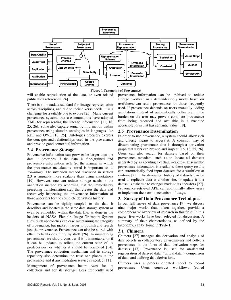
Provenance Taxonomy
Use of Provenance
Subject of Provenance
Provenance Representation
Storing Provenance
Data Quality
Audit Trail
Replication
Attribution
Process Oriented
Granularity
Representation Scheme
Annotation
Inversion
Informational
Data Oriented
Contents
SyntacticInformation
SemanticInformation
Fine GrainedCoarseGrained
Scalability
Provenance Dissemination
Overhead
Visual Graph
Queries
Service API
Figure 1 Taxonomy of Provenance
will enable reproduction of the data, or even related publication references [24]. There is no metadata standard for lineage representation across disciplines, and due to their diverse needs, it is a challenge for a suitable one to evolve [25]. Many current provenance systems that use annotations have adopted XML for representing the lineage information [11, 18, 25, 26]. Some also capture semantic information within provenance using domain ontologies in languages like RDF and OWL [18, 25]. Ontologies precisely express the concepts and relationships used in the provenance and provide good contextual information.
2.4 Provenance Storage Provenance information can grow to be larger than the data it describes if the data is fine-grained and provenance information rich. So the manner in which the provenance metadata is stored is important to its scalability. The inversion method discussed in section 2.3 is arguably more scalable than using annotations [19]. However, one can reduce storage needs in the annotation method by recording just the immediately preceding transformation step that creates the data and recursively inspecting the provenance information of those ancestors for the complete derivation history. Provenance can be tightly coupled to the data it describes and located in the same data storage system or even be embedded within the data file, as done in the headers of NASA Flexible Image Transport System files. Such approaches can ease maintaining the integrity of provenance, but make it harder to publish and search just the provenance. Provenance can also be stored with other metadata or simply by itself [26]. In maintaining provenance, we should consider if it is immutable, or if it can be updated to reflect the current state of its predecessors, or whether it should be versioned [14]. The provenance collection mechanism and its storage repository also determine the trust one places in the provenance and if any mediation service is needed [11]. Management of provenance incurs costs for its collection and for its storage. Less frequently used
provenance information can be archived to reduce storage overhead or a demand-supply model based on usefulness can retain provenance for those frequently used. If provenance depends on users manually adding annotations instead of automatically collecting it, the burden on the user may prevent complete provenance from being recorded and available in a machine accessible form that has semantic value [18].
2.5 Provenance Dissemination In order to use provenance, a system should allow rich and diverse means to access it. A common way of disseminating provenance data is through a derivation graph that users can browse and inspect [16, 18, 25, 26]. Users can also search for datasets based on their provenance metadata, such as to locate all datasets generated by a executing a certain workflow. If semantic provenance information is available, these query results can automatically feed input datasets for a workflow at runtime [25]. The derivation history of datasets can be used to replicate data at another site, or update it if a dataset is stale due to changes made to its ancestors [27]. Provenance retrieval APIs can additionally allow users to implement their own mechanism of usage.
3. Survey of Data Provenance Techniques In our full survey of data provenance [9], we discuss nine major works that, taken together, provide a comprehensive overview of research in this field. In this paper, five works have been selected for discussion. A summary of their characteristics, as defined by the taxonomy, can be found in Table 1.
3.1 Chimera Chimera [27] manages the derivation and analysis of data objects in collaboratory environments and collects provenance in the form of data derivation steps for datasets [17]. Provenance is used for on-demand regeneration of derived data (“virtual data”), comparison of data, and auditing data derivations. Chimera uses a process oriented model to record provenance. Users construct workflows (called
SIGMOD Record, Vol. 34, No. 3, Sept. 2005 33

derivation graphs or DAGs) using a Virtual Data Language (VDL) [17, 27]. The VDL conforms to a schema that represents data products as abstract typed datasets and their materialized replicas. Datasets can be files, tables, and objects of varying granularity, though the prototype supports only files. Computational process templates, called transformations, are scripts in the file system and, in future, web services [17]. The parameterized instance of the transformations, called derivations, can be connected to form workflows that consume and produce replicas. Upon execution, workflows automatically create invocation objects for each derivation in the workflow, annotated with runtime information of the process. Invocation objects are the glue that link input and output data products, and they constitute an annotation scheme for representing the provenance. Semantic information on the dataset derivation is not collected. The lineage in Chimera is represented in VDL that maps to SQL queries in a relational database, accessed through a virtual data catalog (VDC) service [27]. Metadata can be stored in a single VDC, or distributed over multiple VDC repositories with inter-catalog references to data and processes, to enable scaling. Lineage information can be retrieved from the VDC using queries written in VDL that can, for example, recursively search for derivations that generated a particular dataset. A virtual data browser that uses the VDL queries to interactively access the catalog is proposed [27]. A novel use of provenance in Chimera is to plan and estimate the cost of regenerating datasets. When a dataset has been previously created and it needs to be regenerated (e.g. to create a new replica), its provenance guides the workflow planner in selecting an optimal plan for resource allocation [17, 27].
3.2 myGrid myGrid provides middleware in support of in silico (computational laboratory) experiments in biology, modeled as workflows in a Grid environment [18]. myGrid services include resource discovery, workflow enactment, and metadata and provenance management, which enable integration and present a semantically enhanced information model for bio-informatics. myGrid is service-oriented and executes workflows written in XScufl language using the Taverna engine [18]. A provenance log of the workflow enactment contains the services invoked, their parameters, the start and end times, the data products used and derived, and ontology descriptions, and it is automatically recorded when the workflow executes. This process-oriented workflow derivation log is inverted to infer the provenance for the intermediate and final data products. Users need to annotate workflows and services with semantic descriptions to enable this inference and have the semantic metadata carried over to the data products.
In addition to contextual and organizational metadata such as owner, project, and experiment hypothesis, ontological terms can also be provided to describe the data and the experiment [8]. XML, HTML, and RDF are used to represent syntactic and semantic provenance metadata using the annotation scheme [14]. The granularity at which provenance can be stored is flexible and is any resource identifiable by an LSID [18]. The myGrid Information Repository (mIR) data service is a central repository built over a relational database to store metadata about experimental components [18]. A number of ways are available for knowledge discovery using provenance. For instance, the semantic provenance information available as RDF can be viewed as a labeled graph using the Haystack semantic web browser [18]. COHSE (Conceptual Open Hypermedia Services Environment), a semantic hyperlink utility, is another tool used to build a semantic web of provenance. Here, semantically annotated provenance logs are interlinked using an ontology reasoning service and displayed as a hyperlinked web page. Provenance information generated during the execution of a workflow can also trigger the rerun of another workflow whose input data parameters it may have updated.
3.3 CMCS The CMCS project is an informatics toolkit for collaboration and metadata-based data management for multi-scale science [24, 25]. CMCS manages heterogeneous data flows and metadata across multi-disciplinary sciences such as combustion research, supplemented by provenance metadata for establishing the pedigree of data. CMCS uses the Scientific Annotation Middleware (SAM) repository for storing URL referenceable files and collections [25]. CMCS uses an annotation scheme to associate XML metadata properties with the files in SAM and manages them through a Distributed Authoring and Versioning (WebDAV) interface. Files form the level of granularity and all resources such as data objects, processes, web services, and bibliographic records are modeled as files. Dublin Core (DC) verbs like Has Reference, Issued, and Is Version Of are used as XML properties for data files and semantically relate them to their deriving processes through XLink references in SAM [24]. DC elements like Title and Creator, and user-defined metadata can provide additional context information. Heterogeneous metadata schemas are supported by mapping them to standard DC metadata terms using XSLT translators. Direct association of provenance metadata with the data object makes this a data-oriented model. There is no facility for automated collection of lineage from a workflow’s execution. Data files and their metadata are populated by DAV-aware applications in workflows or manually entered by scientists through a portal interface [25]. Provenance metadata properties
34 SIGMOD Record, Vol. 34, No. 3, Sept. 2005

Table 1 Summary of characteristics of surveyed data provenance techniques
Chimera myGRID CMCS ESSW Trio
Applied Domain
Physics, Astronomy Biology Chemical Sciences Earth Sciences None
Workflow Type Script Based Service Oriented Service Oriented Script Based Database Query
Use of Provenance Informational; Audit; Data Replication
Context Information; Re-enactment
Informational; update data Informational Informational; up
date propagation Subject Process Process Data Both Data
Granularity Abstract datasets (Presently files)
Abstract resources having LSID Files Files Tuples in
Database Representation Scheme
Virtual Data Language Annotations
XML/RDF Annotations
DublinCore XML Annotations
XML/RDF Annotations
Query Inversion
Semantic Info. No Yes Yes Proposed No Storage Repository/ Backend
Virtual Data Catalog/ Relational DB
mIR repository/ Relational DB
SAM over DAV/ Relational DB
Lineage Server/ Relational DB Relational DB
User Overhead User defines derivations;
Automated WF trace
User defines Service semantics; Automated
WF Trace
Manual: Apps use DAV APIs; Users
use portal
Use Libraries to generate
provenance
Inverse queries automatically
generated Scalability Addressed Yes No No Proposed No
Dissemination Queries Semantic browser; Lineage graph
Browser;Queries; GXL/RDF Browser SQL/TriQL
Queries can be queried from SAM using generic WebDAV clients. Special portlets allow users to traverse the provenance metadata for a resource as a web page with hyperlinks to related data, or as a labeled graph represented in the Graphics eXchange Language (GXL). The provenance information can also be exported to RDF that semantic agents can use to infer relationships between resources. Provenance metadata that indicate data modification can generate notifications that trigger workflow execution to update dependent data products.
3.4 ESSW The Earth System Science Workbench (ESSW) [28] is a metadata management and data storage system for earth science researchers. Lineage is a key facet of the metadata created in the workbench, and is used for detecting errors in derived data products and in determining the quality of datasets. ESSW uses a scripting model for data processing i.e. all data manipulation is done through scripts that wrap existing scientific applications [26]. The sequence of invocation of these scripts by a master workflow script forms a DAG. Data products at the granularity of files are consumed and produced by the scripts, with each data product and script having a uniquely labeled metadata object. As the workflow script invokes individual scripts, these scripts, as part of their execution, compose XML metadata for themselves and the data products they generate. The workflow script links the data flow between successive scripts using their metadata ids to form the lineage trace for all data products, represented as annotations. By chaining the scripts and the data using parent-child links, ESSW is balanced between data and process oriented lineage.
ESSW puts the onus on the script writer to record the metadata and lineage using templates and libraries that are provided. The libraries store metadata objects as files in a web accessible location and the lineage separately in a relational database [26]. Scalability is not currently addressed though it is proposed to federate lineage across organizations. The metadata and lineage information can be navigated as a workflow DAG through a web browser that uses PHP scripts to access the lineage database [28]. Future work includes encoding lineage information semantically as RDF triples to help answer richer queries [26].
3.5 Trio Cui and Widom [22, 29] trace lineage information for view data in data warehouses. The Trio project [23] leverages some of this work in a proposed database system which has data accuracy and data lineage as inherent components. While data warehouse mining and updation motivates lineage tracking in this project, any e-science system that uses database queries and functions to model workflows and data transformations can apply such techniques. A database view can be modeled as a query tree that is evaluated bottom-up, starting with leaf operators having tables as inputs and successive parent operators taking as input the result of a child operator [22]. For ASPJ (Aggregate-Select-Project-Join operator) views, it is possible to create an inverse query of the view query that operates on the materialized view, and recursively moves down the query tree to identity the source tables in the leaves that form the view data’s lineage [22]. Trio [23] uses this inversion model to automatically determine the source data for tuples created by view
SIGMOD Record, Vol. 34, No. 3, Sept. 2005 35

queries. The inverse queries are recorded at the granularity of a view tuple and stored in a special Lineage table. This direct association of lineage with tuples makes this a data-oriented provenance scheme. Mechanisms to handle (non-view) tuples created by insert and update queries, and through user-defined functions are yet to be determined. Lineage in Trio is simply the source tuples and the view query that created the view tuple, with no semantic metadata recorded. Scalability is not specifically addressed either. Other than querying the Lineage table, some special purpose constructs will be provided for retrieving lineage information through a Trio Query Language (TriQL).
4. Conclusion In this paper, we presented a taxonomy to understand and compare provenance techniques used in e-science projects. The exercise shows that provenance is still an exploratory field and several open research questions are exposed. Ways to federate provenance information and assert its truthfulness need study for it to be usable across organizations [12]. Evolution of metadata and service interface standards to manage provenance in diverse domains will also contribute to a wider adoption of provenance and promote its sharing [11]. The ability to seamlessly represent provenance of data derived from both workflows and databases can help in its portability. Ways to store provenance about missing or deleted data (phantom lineage [23]) require further consideration. Finally, a deeper understanding of provenance is needed to identify novel ways to leverage it to its full potential.
5. References [1] J. Brase, "Using Digital Library Techniques - Registration of Scientific Primary Data," in ECDL, 2004. [2] D. G. Clarke and D. M. Clark, "Lineage," in Elements of Spatial Data Quality, 1995. [3] J. L. Romeu, "Data Quality and Pedigree," in Material Ease, 1999. [4] H. V. Jagadish and F. Olken, "Database Management for Life Sciences Research," in SIGMOD Record, vol. 33, 2004. [5] "Access to genetic resources and Benefit-Sharing (ABS) Program," United Nations University, 2003. [6] P. Buneman, S. Khanna, and W. C. Tan, "Why and Where: A Characterization of Data Provenance," in ICDT, 2001. [7] D. P. Lanter, "Design of a Lineage-Based Meta-Data Base for GIS," in Cartography and Geographic Information Systems, vol. 18, 1991. [8] M. Greenwood, C. Goble, R. Stevens, J. Zhao, M. Addis, D. Marvin, L. Moreau, and T. Oinn, "Provenance of e-Science Experiments - experience from Bioinformatics," in Proceedings of the UK OST e-Science 2nd AHM, 2003. [9] Y. L. Simmhan, B. Plale, and D. Gannon, "A Survey of Data Provenance Techniques," in Technical Report TR-618: Computer Science Department, Indiana University, 2005. [10] R. Bose and J. Frew, "Lineage retrieval for scientific data processing: a survey," in ACM Comput. Surv., vol. 37, 2005. [11] S. Miles, P. Groth, M. Branco, and L. Moreau, "The requirements of recording and using provenance in e-Science
experiments," in Technical Report, Electronics and Computer Science, University of Southampton, 2005. [12] D. Pearson, "Presentation on Grid Data Requirements Scoping Metadata & Provenance," in Workshop on Data Derivation and Provenance, Chicago, 2002. [13] G. Cameron, "Provenance and Pragmatics," in Workshop on Data Provenance and Annotation, Edinburgh, 2003. [14] C. Goble, "Position Statement: Musings on Provenance, Workflow and (Semantic Web) Annotations for Bioinformatics," in Workshop on Data Derivation and Provenance, Chicago, 2002. [15] P. P. da Silva, D. L. McGuinness, and R. McCool, "Knowledge Provenance Infrastructure," in IEEE Data Engineering Bulletin, vol. 26, 2003. [16] H. Galhardas, D. Florescu, D. Shasha, E. Simon, and C.-A. Saita, "Improving Data Cleaning Quality Using a Data Lineage Facility," in DMDW, 2001. [17] I. T. Foster, J. S. Vöckler, M. Wilde, and Y. Zhao, "The Virtual Data Grid: A New Model and Architecture for Data-Intensive Collaboration," in CIDR, 2003. [18] J. Zhao, C. A. Goble, R. Stevens, and S. Bechhofer, "Semantically Linking and Browsing Provenance Logs for E-science," in ICSNW, 2004. [19] A. Woodruff and M. Stonebraker, "Supporting Fine-grained Data Lineage in a Database Visualization Environment," in ICDE, 1997. [20] B. Plale, D. Gannon, D. Reed, S. Graves, K. Droegemeier, B. Wilhelmson, and M. Ramamurthy, "Towards Dynamically Adaptive Weather Analysis and Forecasting in LEAD," in ICCS workshop on Dynamic Data Driven Applications, 2005. [21] D. Bhagwat, L. Chiticariu, W. C. Tan, and G. Vijayvargiya, "An Annotation Management System for Relational Databases," in VLDB, 2004. [22] Y. Cui and J. Widom, "Practical Lineage Tracing in Data Warehouses," in ICDE, 2000. [23] J. Widom, "Trio: A System for Integrated Management of Data, Accuracy, and Lineage," in CIDR, 2005. [24] C. Pancerella, J. Hewson, W. Koegler, D. Leahy, M. Lee, L. Rahn, C. Yang, J. D. Myers, B. Didier, R. McCoy, K. Schuchardt, E. Stephan, T. Windus, K. Amin, S. Bittner, C. Lansing, M. Minkoff, S. Nijsure, G. v. Laszewski, R. Pinzon, B. Ruscic, Al Wagner, B. Wang, W. Pitz, Y. L. Ho, D. Montoya, L. Xu, T. C. Allison, W. H. Green, Jr, and M. Frenklach, "Metadata in the collaboratory for multi-scale chemical science," in Dublin Core Conference, 2003. [25] J. Myers, C. Pancerella, C. Lansing, K. Schuchardt, and B. Didier, "Multi-Scale Science, Supporting Emerging Practice with Semantically Derived Provenance," in ISWC workshop on Semantic Web Technologies for Searching and Retrieving Scientific Data, 2003. [26] R. Bose and J. Frew, "Composing Lineage Metadata with XML for Custom Satellite-Derived Data Products," in SSDBM, 2004. [27] I. T. Foster, J.-S. Vöckler, M. Wilde, and Y. Zhao, "Chimera: A Virtual Data System for Representing, Querying, and Automating Data Derivation," in SSDBM, 2002. [28] J. Frew and R. Bose, "Earth System Science Workbench: A Data Management Infrastructure for Earth Science Products," in SSDBM, 2001. [29] Y. Cui and J. Widom, "Lineage tracing for general data warehouse transformations," in VLDB Journal, vol. 12, 2003.
36 SIGMOD Record, Vol. 34, No. 3, Sept. 2005

A Notation and System for Expressing and Executing
Cleanly Typed Workflows on Messy Scientific Data
Yong Zhao1
Jed Dobson2
Ian Foster1,3
Luc Moreau4 Michael Wilde
3
1 Department of Computer Science, University of Chicago, Chicago, IL 60637, U.S.A. 2 Department of Psychology, Dartmouth College, Hanover, NH 03755, U.S.A.
3 Mathematics and Computer Science Division, Argonne National Laboratory, Argonne, IL 60439, U.S.A. 4 School of Electronics and Computer Science, University of Southampton, Southampton, U.K.
Abstract
The description, composition, and execution of
even logically simple scientific workflows are
often complicated by the need to deal with
“messy” issues like heterogeneous storage
formats and ad-hoc file system structures. We
show how these difficulties can be overcome
via a typed, compositional workflow notation
within which issues of physical representation
are cleanly separated from logical typing, and
by the implementation of this notation within
the context of a powerful runtime system that
supports distributed execution. The resulting
notation and system are capable both of
expressing complex workflows in a simple,
compact form, and of enacting those
workflows in distributed environments. We
apply our technique to cognitive neuroscience
workflows that analyze functional MRI image
data, and demonstrate significant reductions in
code size relative to other approaches.
1 Introduction
When constructing workflows that operate on large and
complex datasets, the ability to describe and introspect
on the types of both datasets and workflow components
can be invaluable, enabling discovery, type checking,
composition, and iteration over compound datasets.
Such typing should in principle be straightforward,
because of the hierarchical structure of most scientific
datasets. For example, in the functional Magnetic
Resonance Imaging (fMRI) applications used for
illustrative purposes in this paper, we find a hierarchical
structure of studies, groups, subjects, experimental runs,
and images (see Figure 1). A typical application might
build a new study by applying a program to each image
in each run for each subject in each group in a study.
Unfortunately, we find that such clean logical
structures are typically represented in terms of messy
physical constructs (e.g., metadata encoded in directory
and file names) employed in ad-hoc ways. For example,
the fMRI physical representation is a nested directory
structure, with ultimately a single 3D image (“volume”)
represented by two files located in the same directory,
distinguished only by file name suffix (Figure 1).
Such messy physical representations make program
development, composition, and execution unnecessarily
difficult. While we can incorporate knowledge of file
system layouts and file formats into application
programs and scripts, the resulting code is hard to write
and read, cannot easily be adapted to different
representations, and is not clearly typed.
Figure 1: fMRI structure, logical (left) & physical (right)
We have previously proposed that these concerns be
addressed by separating abstract structure and physical
representation [1]. (Woolf et al. [2] have recently
proposed similar ideas.) We describe here the design,
implementation, and evaluation of a notation that
achieve this separation.
We call this notation a virtual data language (VDL)
because its declarative structure allows datasets to be
defined prior to their generation and without regard to
their location and representation. For example, given a
VDL procedure “Run Y=foo_run(Run X)” that builds a
new run Y by applying a program ‘foo’ to each image in
run X (X and Y being dataset variables of type Run), we
can specify via the statement “run2=foo_run(run1)” that
dataset “run2” was (or, alternatively, will be) derived
from dataset “run1.” Independence from location and
DBIC Archive Study_2004.0521.hgd Group 1 Subject_2004.e024 volume_anat.img volume_anat.hdr bold1_001.img bold1_001.hdr ... bold1_275.img bold1_275.hdr ... bold5_001.img ... snrbold*_* ...air* ... Group 5 ... Study ...
DBIC Archive Study #’2004 0521 hgd’ Group #1 Subject #’2004 e024’ Anatomy high-res volume Functional Runs run #1 volume #001 ... volume #275 ... run #5 volume #001 ... volume #242 … Group #5 ... Study #...
SIGMOD Record, Vol. 34, No. 3, Sept. 2005 37

representation is achieved via the use of XML Dataset
Typing and Mapping (XDTM) [3] mechanisms, which
allow the types of datasets and procedures to be defined
abstractly, in terms of XML Schema. Separate mapping
descriptors then define how such abstract data
structures translate to physical representations. Such
descriptors specify, for example, how to access the
physical files associated with “run1” and “run2.”
VDL’s declarative and typed structure makes it easy
to define increasingly complex procedures via
composition. For example, a procedure “Subject Y =
foo_subject(Subject X)” might apply “foo_run” to each
run in a supplied subject. The repeated application of
such compositional forms can ultimately define large
directed acyclic graphs (DAGs) comprising thousands
or even millions of calls to “atomic transformations”
that each operate on just one or two image files.
The expansion of dataset definitions expressed in
VDL into DAGs, and the execution of these DAGs as
workflows in uni- or multi-processor environments, is
the task of an underlying virtual data system (VDS).
We have applied our techniques to fMRI data
analysis problems [4]. We have modeled a variety of
dataset types (and their corresponding physical
representations) and constructed and executed
numerous computational procedures and workflows
that operate on those datasets. Quantitative studies of
code size suggest that our VDL and VDS facilitate
workflow expression, and hence improve productivity.
We summarize the contributions of this paper as
follows:
(1) the design of a practical workflow notation and
system that separate logical and physical
representation to allow for the construction of
complex workflows on messy data using cleanly
typed computational procedures;
(2) solutions to practical problems that arise when
implementing such a notation within the context of
a distributed system within which datasets may be
persistent or transient, and both replicated and
distributed; and
(3) a demonstration and evaluation of the technology
via the encoding and execution of large fMRI
workflows in a distributed environment.
The rest of the paper is as follows. In Section 2, we
review related work. In Section 3, we introduce the
XDTM model and in Section 4 we describe VDL, using
an fMRI application for illustration. In Section 5 we
describe our implementation, and in Section 6 we
conclude with an assessment of results and approach.
2 Related Work
The Data Format Description Language (DFDL)
[5], like XDTM, uses XML Schema to describe abstract
data models that specify data structures independent
from their physical representations. DFDL is concerned
with describing legacy data files and complex binary
formats, while XDTM focuses on describing data that
spans files and directories. Thus, the two systems can
potentially be used together.
XPDL [6], BPEL, and WSDL also use XML
Schema to describe data or message types, but assume
that data is represented in XML; in contrast, XDTM can
describe “messy” real-world data. Ptolemy [7] and
Kepler [8] provide a static typing system; Taverna [9]
and Triana [10] do not mandate typing. The ability to
map logical types from/to physical representations is
not provided by these languages and systems.
When composing programs into workflows, we
must often convert logical types and/or physical
representations to make data accessible to downstream
programs. XPDL employs scripting languages such as
JavaScript to select subcomponents of a data type, and
BPEL uses XPath expressions in Assign statements for
data conversion. Our VDL permits the declarative
specification of a rich set of data conversion operations
on composite data structures and substructures.
BPEL, YAWL, Taverna, and Triana emphasize web
service invocation, while Ptolemy, Kepler, and XPDL
are concerned primarily with composing applications.
XDTM defines an abstract transformation interface that
is agnostic to the procedure invoked, and its binding
mechanism provides the flexibility to invoke either web
services or applications as needed.
VDL’s focus on DAGs limits the range of programs
that can be expressed relative to some other systems.
However, we emphasize that workflows similar to those
presented here are extremely common in scientific
computing, in domains including astronomy,
bioinformatics, and geographical information systems.
VDL can be extended with conditional constructs (for
example) if required, but we have not found such
extensions necessary to date.
Many workflow languages allow sequential,
parallel, and recursive patterns, but do not directly
support iteration. Taverna relies on its workflow engine
to run a process multiple times when a collection is
passed to a singleton-argument process. Kepler adopts a
functional operator ‘map’ to apply a function that
operates on singletons to collections. VDL’s typing
supports flexible iteration over datasets—and also type
checking, composition, and selection.
3 XDTM Overview
In XDTM, a dataset’s logical structure is specified
via a subset of XML Schema, which defines primitive
scalar data types such as Boolean, Integer, String, Float,
and Date, and also allows for the definition of complex
types via the composition of simple and complex types.
A dataset’s physical representation is defined by a
mapping descriptor, which describes how each element
in the dataset’s logical schema is stored in, and fetched
38 SIGMOD Record, Vol. 34, No. 3, Sept. 2005

from, physical structures such as directories, files, and
database tables. In order to permit reuse for different
datasets, mapping descriptors can refer to external
parameters for such things as dataset location(s).
In order to access a dataset, we need to know three
things: its type schema, its mapping descriptor, and the
value(s) of any external parameter(s). These three
components can be grouped to form a dataset handle.
Note that multiple mappings may be defined for the
same logical schema (i.e., for a single logical type). For
example, an array of numbers might in different
contexts be physically represented as a set of relations,
a text file, a spreadsheet, or an XML document.
XDTM defines basic constructs for defining and
associating physical representations with XML
structures. However, it does not speak to how we write
programs that operate on XDTM-defined data: a major
focus of the work described here.
4 XDTM-Based Virtual Data Language
Our XDTM-based Virtual Data Language (VDL)—
derived loosely from an earlier VDL [11], which dealt
solely with untyped files—allows users to define
procedures that accept, return, and operate on datasets
with type, representation, and location defined by
XDTM. We introduce the principal features of VDL via
an example from fMRI data analysis.
4.1 Application Example
fMRI datasets are derived by scanning the brains of
subjects as they perform cognitive or manual tasks. The
raw data for a typical study might consist of three
subject groups with 20 subjects per group, five
experimental runs per subject, and 300 volume images
per run, yielding 90,000 volumes and over 60 GB of
data. A fully processed and analyzed study dataset can
contain over 1.2 million files. In a typical year at the
Dartmouth Brain Imaging Center, about 60 researchers
preprocess and analyze about 20 concurrent studies.
Experimental subjects are scanned once to obtain a
high-resolution image of their brain anatomy
(“anatomical volume”), then scanned with a low-
resolution imaging modality at rapid intervals to
observe the effects of blood flow from the “BOLD”
(blood oxygenated level dependant) signal while
performing some task (“functional runs”). These
images are pre-processed and subjected to intensive
analysis that begins with image processing and
concludes with a statistical analysis of correlations
between stimuli and neural activity.
4.2 VDL Type System
VDL uses a C-like syntax to represent XML Schema
types. (There is a straightforward mapping from this
syntax to XML Schema.) For example, the first twelve
lines of Figure 2 include the VDL types that we use to
represent the data objects of Figure 1. (We discuss the
procedures later.) Some corresponding XML Schema
type definitions are in Figure 3. A Volume contains a
3D image of a volumetric slice of a brain image,
represented by an Image (voxels) and a Header
(scanner metadata). As we do not manipulate the
contents of those objects directly within this VDL
program, we define their types simply as (opaque)
String. A time series of volumes taken from a
functional scan of one subject, doing one task, forms a
Run. In typical experiments, each Subject has multiple
input and normalized runs, and anatomical data, Anat.
Figure 2: VDL Dataset Type and Procedure Examples
Specific output formats involved in processing raw
input volumes and runs may include outputs from
various image processing tools, such as the automated
image registration (AIR) suite. The type Air
corresponds to one dataset type created by these tools.
type Volume { Image img; Header hdr; } type Image String; type Header String; type Run { Volume v[ ]; } type Anat Volume; type Subject { Anat anat; Run run [ ]; Run snrun [ ]; } type Group { Subject s[ ]; } type Study { Group g[ ]; } type Air String; type AirVector { Air a[ ]; } type Warp String; type NormAnat {Anat aVol; Warp aWarp; Volume nHires;} airsn_subject( Subject s, Volume atlas, Air ashrink, Air fshrink ) { NormAnat a = anatomical(s.anat, atlas, ashrink); Run r, snr; foreach r in s.run { snr = functional ( r, a, fshrink ); s.snrun[ name(r) ] = snr; } } (Run snr) functional( Run r, NormAnat a, Air shrink ) { Run yroRun = reorientRun( r , "y" ); Run roRun = reorientRun( yroRun , "x" ); Volume std = roRun[0]; Run rndr = random_select(roRun, .1); //10% sample AirVector rndAirVec = align_linearRun(rndr, std, 12, 1000, 1000, [81,3,3]); Run reslicedRndr = resliceRun( rndr,rndAirVec,"o","k"); Volume meanRand = softmean(reslicedRndr, "y", null ); Air mnQAAir = alignlinear(a.nHires, meanRand,6,1000,4, [81,3,3]); Volume mnQA = reslice(meanRand, mnQAAir, "o","k"); Warp boldNormWarp = combinewarp(shrink, a.aWarp, mnQAAir); Run nr = reslice_warp_run( boldNormWarp, roRun ); Volume meanAll = strictmean ( nr, "y", null ) Volume boldMask = binarize( meanAll, "y" ); snr = gsmoothRun( nr, boldMask, 6, 6, 6); }
SIGMOD Record, Vol. 34, No. 3, Sept. 2005 39
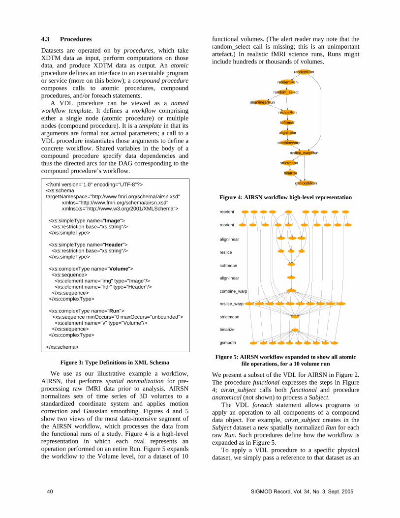
4.3 Procedures
Datasets are operated on by procedures, which take
XDTM data as input, perform computations on those
data, and produce XDTM data as output. An atomic
procedure defines an interface to an executable program
or service (more on this below); a compound procedure
composes calls to atomic procedures, compound
procedures, and/or foreach statements.
A VDL procedure can be viewed as a named
workflow template. It defines a workflow comprising
either a single node (atomic procedure) or multiple
nodes (compound procedure). It is a template in that its
arguments are formal not actual parameters; a call to a
VDL procedure instantiates those arguments to define a
concrete workflow. Shared variables in the body of a
compound procedure specify data dependencies and
thus the directed arcs for the DAG corresponding to the
compound procedure’s workflow.
Figure 3: Type Definitions in XML Schema
We use as our illustrative example a workflow,
AIRSN, that performs spatial normalization for pre-
processing raw fMRI data prior to analysis. AIRSN
normalizes sets of time series of 3D volumes to a
standardized coordinate system and applies motion
correction and Gaussian smoothing. Figures 4 and 5
show two views of the most data-intensive segment of
the AIRSN workflow, which processes the data from
the functional runs of a study. Figure 4 is a high-level
representation in which each oval represents an
operation performed on an entire Run. Figure 5 expands
the workflow to the Volume level, for a dataset of 10
functional volumes. (The alert reader may note that the
random_select call is missing; this is an unimportant
artefact.) In realistic fMRI science runs, Runs might
include hundreds or thousands of volumes.
reorientRun
reorientRun
reslice_warpRun
random_select
alignlinearRun
resliceRun
softmean
alignlinear
combinewarp
strictmean
gsmoothRun
binarize
Figure 4: AIRSN workflow high-level representation
reorient/01
reorient/02
reslice_warp/22
alignlinear/03 alignlinear/07alignlinear/11
reorient/05
reorient/06
reslice_warp/23
reorient/09
reorient/10
reslice_warp/24
reorient/25
reorient/51
reslice_warp/26
reorient/27
reorient/52
reslice_warp/28
reorient/29
reorient/53
reslice_warp/30
reorient/31
reorient/54
reslice_warp/32
reorient/33
reorient/55
reslice_warp/34
reorient/35
reorient/56
reslice_warp/36
reorient/37
reorient/57
reslice_warp/38
reslice/04 reslice/08reslice/12
gsmooth/41
strictmean/39
gsmooth/42gsmooth/43gsmooth/44 gsmooth/45 gsmooth/46 gsmooth/47 gsmooth/48 gsmooth/49 gsmooth/50
softmean/13
alignlinear/17
combinewarp/21
binarize/40
reorient
reorient
alignlinear
reslice
softmean
alignlinear
combine_warp
reslice_warp
strictmean
binarize
gsmooth
Figure 5: AIRSN workflow expanded to show all atomic
file operations, for a 10 volume run
We present a subset of the VDL for AIRSN in Figure 2.
The procedure functional expresses the steps in Figure
4; airsn_subject calls both functional and procedure
anatomical (not shown) to process a Subject.
The VDL foreach statement allows programs to
apply an operation to all components of a compound
data object. For example, airsn_subject creates in the
Subject dataset a new spatially normalized Run for each
raw Run. Such procedures define how the workflow is
expanded as in Figure 5.
To apply a VDL procedure to a specific physical
dataset, we simply pass a reference to that dataset as an
<?xml version="1.0" encoding="UTF-8"?> <xs:schema targetNamespace="http://www.fmri.org/schema/airsn.xsd" xmlns="http://www.fmri.org/schema/airsn.xsd" xmlns:xs="http://www.w3.org/2001/XMLSchema"> <xs:simpleType name="Image"> <xs:restriction base="xs:string"/> </xs:simpleType> <xs:simpleType name="Header"> <xs:restriction base="xs:string"/> </xs:simpleType> <xs:complexType name="Volume"> <xs:sequence> <xs:element name="img" type="Image"/> <xs:element name="hdr" type="Header"/> </xs:sequence> </xs:complexType> <xs:complexType name="Run">
<xs:sequence minOccurs="0 maxOccurs="unbounded"> <xs:element name="v" type="Volume"/> </xs:sequence> </xs:complexType> </xs:schema>
40 SIGMOD Record, Vol. 34, No. 3, Sept. 2005

actual parameter. The resulting call will execute
correctly regardless of the physical representation of a
passed dataset (assuming that the dataset and procedure
have matching logical types). Internally, dataset
references take the form of handles, which, as described
in Section 3, contain type, mapping, and location
information. As in languages in which every variable is
an object reference, handles are never seen by the user.
4.4 Invoking Programs and Services
A workflow such as Figure 2 must ultimately invoke
external executable programs and/or Web Services.
VDL atomic procedures define the necessary
interfaces, specifying the name of the program or
service to be invoked, how to set up its execution
environment, how program arguments or service
messages should be mapped from and to VDL
procedure arguments, and what physical data objects
need to be moved to and from remote execution sites.
Figure 6 Program Invocation
For example, the procedure alignlinear called in
Figure 2 defines a VDL interface to the AIR utility of
the same name. There are two important things to
understand about this definition. First, the VDS ensures
that if this call is executed on a remote computer (as is
usually the case in a distributed environment), the
physical representations of datasets passed as input
arguments are transferred to the remote site, thus
ensuring that the executable can access the required
physical files. In the case of output data (e.g., “Air a”),
the physical data is left on the remote site, registered in
a replica location service, and optionally copied to
another specified site to create an additional replica
(which often serves as an archival copy).
Second, the statements in the body assemble the
command to invoke the program, so that for example
the VDL call:
Air a = alignlinear(t1a, t3, 12, 1000, 1000, [81 3 3]) requests the execution of the following command:
alignlinear a.air t1a.hdr t3.hdr -m 12 \ -t1 1000 -t2 1000 -s 81 3 3
Alternative atomic procedures can be provided to
specify Web Service interfaces to the utilities. These
alternative procedures would implement the same
procedure prototype, but provide a different body.
5 Implementation
We have developed a prototype system that can process
VDL type definitions and mappings, convert a typed
workflow definition into an executable DAG, expand
DAG nodes dynamically to process sub-components of
a compound dataset, and submit and execute the
resulting DAG in a Grid environment. The separation
of dataset type and physical representation that we
achieve with VDL can facilitate various runtime
optimizations and graph rewriting operations [12].
Our prototype does not yet include a parser for the
syntax presented here. However, the prototype does
implement the runtime operations needed to support
typed VDL dataset processing and execution, which is
the principal technical challenge of implementing VDL.
We have also verified that we can invoke equivalent
services and applications from the same VDL.
The prototype extends an earlier VDS
implementation with features to handle data typing and
mapping. We use the VDS graph traversal mechanism
to generate an abstract DAG in which transformations
are not yet tied to specific applications or services, and
data objects are not yet bound to specific locations and
physical representations. The extended VDS also
enhances the DAG representation by introducing
“foreach” nodes (in addition to the existing “atomic”
nodes) to represent foreach statements in a VDL
procedure. These nodes are expanded at runtime (see
Section 5.2), thus enabling datasets to have a
dynamically determined size.
The abstract DAG is concretized by a Grid planner
called Euryale, which produces a concrete DAG that,
for each node in the input abstract DAG, performs the
following steps. (See Sections 5.1 and 5.2 for details on
how Euryale performs data mapping during these steps,
and expands foreach statements, respectively.)
1. Preprocess:
if (atomic procedure node) {
identify node inputs and outputs;
choose Grid site that meets job requirements;
locate and transfer inputs to that site;
}
else if (foreach node)
expand foreach statement(s) into sub-dag(s);
2. Execute: Submit job or sub-DAG; wait for it to
execute.
3. Postprocess: Check job exit status; transfer and
register outputs; cleanup.
The resulting concrete DAG is executed by the
DAGman (“DAG manager”) tool. DAGman provides
many necessary facilities for workflow execution, such
as logging, job status monitoring, workflow persistence,
and recursive fault recovery. DAGman submits jobs to
Grid sites via the Globus GRAM protocol.
(Air out) alignlinear(Volume std, Volume v, Int m, Int t1, Int t2, Int s[ ] ) { argument = out; argument = get_member(std, hdr); argument = get_member (v, hdr); argument = "-m " m; argument = "-t1" t1; argument = "-t2" t2; argument = "-s " s[0] s[1] s[2]; }
SIGMOD Record, Vol. 34, No. 3, Sept. 2005 41

5.1 Data Mapping
The Eurayle planner needs to operate on the physical
data that lies behind the logical types defined in VDL
procedures. Such operations are accessed via a mapping
descriptor associated with the dataset, which controls
the execution of a mapping driver used to map between
physical and abstract representations. In general, a
mapping driver must implement the functions create-
dataset, store-member, get-member, and get-member-
list. Our prototype employs a table-driven approach to
implement a mapping driver for file-system-stored
datasets. Each table entry specifies: name: the data object name
pattern: the pattern used to match file names
mode: FILE (find matches in directory)
RLS (find matches via replica location service),
ENUM (dataset content is enumerated)
content: used in ENUM mode to list content
When mapping an input dataset, this table is
consulted, the pattern is used to match a directory or
replica location service according to the mode, and the
members of the dataset are enumerated in an in-
memory structure. This structure is then used to expand
foreach statements and to set command-line arguments.
For example, recall from Figure 1 that a Volume is
physically represented as an image/header file pair, and
a Run as a set of such pairs. Furthermore, multiple Runs
may be stored in the same directory, with different
Runs distinguished by a prefix and different Volumes
by a suffix. To map this representation to the logical
Run structure, the pattern ‘boldN*’ is used to identify
all pairs in Run N at a specified location. Thus, the
mapper, when applied to the following eight files,
identifies two runs, one with three Volumes (Run 1) and
the other with one (Run 2).
bold1_001.img bold1_001.hdr
bold1_002.img bold1_002.hdr
bold1_003.img bold1_003.hdr
bold2_007.img bold2_007.hdr
5.2 Dynamic Node Expansion
A node containing a foreach statement must be
expanded prior to execution into a set of nodes: one per
component of the compound data object specified in the
foreach. This expansion is performed at runtime: when
a foreach node is scheduled for execution, the
appropriate mapper function is called on the specified
dataset to determine its members, and for each member
of the dataset identified (e.g., for each Volume in a Run)
a new job is created in a “sub-DAG.”
The new sub-DAG is submitted for execution, and
the main job waits for the sub-DAG to finish before
proceeding. A post-script for the main job takes care of
the transfer and registration of all output files, and the
collection of those files into the output dataset. This
workflow expansion process may itself recurse further
if the subcomponents themselves also include foreach
statements. DAGman provides workflow persistence
even in the face of system failures during recursion.
5.3 Optimizations and Graph Transformation
Since dataset mapping and node expansion are carried
out at run time, we can use graph transformations to
apply optimization strategies. For example, in the
AIRSN workflow, some processes, such as the reorient
of a single Volume, only take a few seconds to run. It is
inefficient to schedule a distinct process for each
Volume in a Run. Rather, we can combine multiple such
processes to run as a single job, thus reducing
scheduling and queuing overhead.
As a second example, the softmean procedure
computes the mean of all Volumes in a Run. For a
dataset with large number of Volumes, this stage is a
bottleneck as no parallelism is engaged. There is also a
practical issue: the executable takes all Volume
filenames as command line arguments, which can
exceed limits defined by the Condor and UNIX shell
tools used within our VDS implementation. Thus, we
transform this node into a tree in which leaf nodes
compute over subsets of the dataset. The process
repeats until we get a single output. The shape of this
tree can be tuned according to available computing
nodes and dataset sizes to achieve optimal parallelism
and avoid command-line length limitations.
6 Evaluation
We have used our prototype system to execute a range
of fMRI workflows with various input datasets on the
Dartmouth Green Grid, which comprises five 12-node
clusters. The dataset mapping mechanism allowed us to
switch input datasets (e.g., from a Run of 80 volumes to
another Run of 120 volumes) without changing either
the workflow definition or the execution system. All
workflows run correctly and achieve speedup.
The primary focus of our work is to increase
productivity [13]. As an approximate measure of this,
we compare in Table 1 the lines of code needed to
express five different fMRI workflows, coded in our
new VDL, with two other approaches, one based on ad-
hoc shell scripts (“Script,” able to execute only on a
single computer) and a second (“Generator”) that uses
Perl scripts to generate older, “pre-XDTM” VDL.
Table 1: Lines of code with different workflow encodings
Workflow Script Generator VDL
GENATLAS1 49 72 6
GENATLAS2 97 135 10
FILM1 63 134 17
FEAT 84 191 13
AIRSN 215 ~400 37
42 SIGMOD Record, Vol. 34, No. 3, Sept. 2005

The new programs are smaller and more readable—
and also provide for type checking, provenance
tracking, parallelism, and distributed execution.
7 Conclusions
We have designed a typed workflow notation and
system that allows workflows to be expressed in terms
of declarative procedures that operate on XML data
types and then executed on diverse physical
representations and on distributed computers. We show
that this notation and system can be used to express
large amounts of distributed computation easily.
The productivity leverage of this approach is
apparent: a small group of developers can define VDL
interfaces to the utility packages used in a research
domain and then create a library of dataset-iteration
functions. This library encapsulates low-level details
concerning how data is grouped, transported,
catalogued, passed to applications, and collected as
results. Other scientists can then use this library to
construct workflows without needing to understand
details of physical representation, and furthermore are
protected by the XDTM type system from forming
workflows that are not type compliant. In addition, the
data management conventions of a research group can
be encoded in XDTM mapping functions, thus making
it easier to maintain order in dataset collections that
may include tens of millions of files.
We next plan to automate the parsing steps that
were performed manually in our prototype, and to
create a complete workflow development and execution
environment for our XDTM-based VDL. We will also
investigate support for services, automation of type
coercions between differing physical representations,
and recording of provenance for large data collections.
Acknowledgements.
This work was supported by the National Science
Foundation GriPhyN Project, grant ITR-800864, the
Mathematical, Information, and Computational
Sciences Division subprogram of the Office of
Advanced Scientific Computing Research, U.S.
Department of Energy, and by the National Institutes of
Health, grants NS37470 and NS44393. We are grateful
to Scott Grafton of the Dartmouth Brain Imaging
Center, and to Jens Voeckler, Doug Scheftner, Ewa
Deelman, Carl Kesselman, and the entire Virtual Data
System team for discussion, guidance, and assistance.
References
[1] Foster, I., Voeckler, J., Wilde, M., Zhao, Y. The Virtual
Data Grid: A New Model and Architecture for Data-
intensive Collaboration. Conference on Innovative Data
Systems Research, Asilomar, CA, January 2003.
[2] Woolf, A., Cramer, R., Gutierrez, M., van Dam, K.,
Kondapalli, S., Latham, S., Lawrence, B., Lowry, R.,
O'Neill, K., Semantic Integration of File-based Data for
Grid Services. Workshop on Semantic Infrastructure for
Grid Computing Applications, 2005.
[3] Moreau, L., Zhao, Y., Foster, I., Voeckler, J. Wilde, M.,
XDTM: XML Dataset Typing and Mapping for
Specifying Datasets. European Grid Conference, 2005.
[4] Van Horn, J.D., Dobson, J., Woodward, J., Wilde, M.,
Zhao, Y., Voeckler, J., Foster, I. Grid-Based Computing
and the Future of Neuroscience Computation, Methods in
Mind, Cambridge: MIT Press (In Press).
[5] Beckerle, M., Westhead, M. GGF DFDL Primer.
Technical report, Global Grid Forum, 2004.
[6] XML Process Definition Language (XPDL) (WFMCTC-
1025). Technical report, Workflow Management
Coalition, Lighthouse Point, Florida, USA, 2002.
[7] Eker, J., Janneck, J., Lee, E., Liu, J., Liu, X., Ludvig, J.,
Neuendorffer, S., Sachs, S., Xiong, Y. Taming
Heterogeneity – the Ptolemy Approach. Proceedings of
the IEEE, 91(1):127-144, January 2003.
[8] Altintas, I., Berkley, C., Jaeger, E., Jones, M.,
Ludäscher, B. and Mock, S., Kepler: An Extensible
System for Design and Execution of Scientific
Workflows. 16th Intl. Conference on Scientific and
Statistical Database Management, 2004.
[9] Oinn, T., Addis, M., Ferris, J., Marvin, D., Senger, M.,
Greenwood, M., Carver, T., Glover, K., Pocock, M.,
Wipat, A., Li, P. Taverna: A Tool for the Composition
and Enactment of Bioinformatics Workflows.
Bioinformatics Journal, 20(17):3045-3054, 2004.
[10] Churches, D., Gombas, G., Harrison, A., Maassen, J.,
Robinson, C., Shields, M., Taylor, I. Wang, I.
Programming Scientific and Distributed Workflow with
Triana Services. Concurrency and Computation:
Practice and Experience, 2005 (in press).
[11] Foster, I., Voeckler, J., Wilde, M., Zhao, Y. Chimera: A
Virtual Data System for Representing, Querying and
Automating Data Derivation. 14th Conference on
Scientific and Statistical Database Management, 2002.
[12] Deelman, E., Blythe, J., Gil, Y., Kesselman, C., Mehta,
G., Vahi, K., Blackburn, K., Lazzarini, A., Arbree, A.,
Cavanaugh, R., Koranda, S. Mapping Abstract
Workflows onto Grid Environments. Journal of Grid
Computing, 1(1). 2003.
[13] Gray, J., Liu, D., Nieto-Santisteban, M., Szalay, A.
Scientific Data Management in the Coming Decade.
Microsoft Research, MSR-TR-2005-10. 2005.
SIGMOD Record, Vol. 34, No. 3, Sept. 2005 43

1
A Taxonomy of Scientific Workflow Systems for Grid Computing
Jia Yu and Rajkumar Buyya*
Grid Computing and Distributed Systems (GRIDS) Laboratory
Department of Computer Science and Software Engineering
The University of Melbourne, Australia
htpp://www.gridbus.org
ABSTRACT With the advent of Grid and application technologies,
scientists and engineers are building more and more
complex applications to manage and process large data sets,
and execute scientific experiments on distributed resources.
Such application scenarios require means for composing
and executing complex workflows. Therefore, many efforts
have been made towards the development of workflow
management systems for Grid computing. In this paper, we
propose a taxonomy that characterizes and classifies
various approaches for building and executing workflows
on Grids. The taxonomy not only highlights the design and
engineering similarities and differences of state-of-the-art in
Grid workflow systems, but also identifies the areas that
need further research.
Keywords Grid computing, Taxonomy, Scientific workflows.
1. INTRODUCTION Grids [9] have emerged as a global cyber-infrastructure for
the next-generation of e-Science applications, by integrating
large-scale, distributed and heterogeneous resources.
Scientific communities, such as high-energy physics,
gravitational-wave physics, geophysics, astronomy, and
bioinformatics, are utilizing Grids to share, manage and
process large data sets. In order to support complex
scientific experiments, distributed resources such as
computational devices, data, applications, and scientific
instruments need to be orchestrated while managing
workflow operations within Grid environments [15].
Scientific workflow is concerned with the automation of
scientific processes in which tasks are structured based on
their control and data dependencies. The workflow
paradigm for scientific applications on Grids offers several
advantages, such as (a) ability to build dynamic
applications which orchestrate distributed resources, (b)
utilizing resources that are located in a particular domain to
increase throughput or reduce execution costs, (c) execution
spanning multiple administrative domains to obtain specific
processing capabilities, and (d) integration of multiple
teams involved in management of different parts of the
experiment workflow – thus promoting inter-organizational
collaborations.
In the recent past, several Grid workflow systems have
been proposed and developed for defining, managing and
executing scientific workflows. In order to enhance
understanding of the field, we propose a taxonomy that
primarily (a) captures architectural styles and (b) identifies
design and engineering similarities and differences between
them. The taxonomy provides an in-depth understanding of
building and executing workflows on Grids. It compares
different approaches and also helps users to decide on
minimum subset of features required for their systems.
The rest of the paper is organized as follows: Section 2
presents taxonomy that classifies approaches based on
major functions and architectural styles of Grid workflow
systems. In Section 3, we map the proposed taxonomy onto
selected Grid workflow systems and conclude in Section 4.
2. TAXONOMY The taxonomy characterizes and classifies approaches of
scientific workflow systems in the context of Grid
computing. It consists of four elements of a Grid workflow
management system: (a) workflow design, (b) workflow
scheduling, (c) fault tolerance and (d) data movement (see
Figure 1). In this section, we look at each element and its
taxonomy briefly. A detailed taxonomy and in depth
discussion on its mapping can be found in [23].
2.1 Workflow Design
Workflow design determines how workflow components
can be defined and composed.
2.1.1 Workflow Structure
A workflow is composed by connecting multiple scientific
tasks according to their dependencies. Workflow structure
indicates the temporal relationship between there tasks. In
general, a workflow can be represented as a Directed
Acyclic Graph (DAG) or a non-DAG.
In DAG-based workflow, workflow structure can be
categorized as sequence, parallelism, and choice.
Sequence is defined as an ordered series of tasks, with one
task starting after a previous task has completed.
Parallelism represents tasks which are performed
concurrently, rather than serially. In choice structured
workflows, a task is selected to execute at run-time when its
associated conditions are true. In addition to all structures
contained in a DAG-based, a non-DAG workflow also
includes iteration structure, in which sections of workflow
tasks in an iteration block are allowed to be repeated.
*Corresponding author, [email protected]
44 SIGMOD Record, Vol. 34, No. 3, Sept. 2005

2
2.1.2 Workflow Model/Specification
Workflow Model (also called workflow specification)
defines a workflow including its task definition and
structure definition. There are two types of workflow
models, namely abstract and concrete.
In the abstract model, a workflow is described in an
abstract form, in which the workflow is specified without
referring to specific Grid resources for task execution. In
contrast, the concrete model binds workflow tasks to
specific resources. Given the dynamic nature of the Grid
environment, it is more suitable for users to define
workflow applications in the abstract model. A full or
partial concrete model can be generated just before or
during workflow execution, according to the current status
of resources.
Figure 1. A taxonomy of scientific workflow systems for Grid computing.
2.1.3 Workflow Composition System
Workflow composition systems are designed for enabling
users to assemble components into workflows. They need
to provide a high level view for the construction of Grid
workflow applications and hide the complexity of
Workflow
Design
Workflow
Scheduling
Fault
Tolerance
Data
Movement
Grid
Workflow
System
Workflow Structure
Workflow
Composition System
Workflow
Model/Specification
DAG
Non-DAG
Sequence
Choice
Iteration
Parallelism
Sequence
Choice
Parallelism
Concrete
Abstract
User-directed Graph-based Modeling
Automatic
Language-based Modeling
Architecture
Scheduling Strategies
Decision Making
Planning Scheme
Decentralized
Hierarchical
Centralized
Global
Local
Static
Dynamic
User-directed
Simulation-based
Prediction-based
Just in-time
Trust-driven
Market-driven
Performance-driven
Checkpoint /Restart
Replication
Alternate Task
Redundancy
Task-level
Workflow-level
Alternate Resource
Retry
User-directed
Automatic
Centralized
Mediated
Peer-to-Peer
User-defined Exception Handling
Rescue workflow
SIGMOD Record, Vol. 34, No. 3, Sept. 2005 45

3
underlying Grid systems. The composition systems are
categorized as user-directed and automatic.
User-directed systems require users to edit workflows
directly. In general, users can use workflow languages such
as Extensible Markup Language (XML) [21] for language-
based modeling and the tools such as Kepler [2] for graph-
based modeling to compose workflows. Compared with
language-based modeling, Graphical representation is very
intuitive and can be handled easily even by a non-expert
user. However, workflow languages are more appropriate
for storing and transfer whereas the graphical representation
is required to be converted into other form for such
manipulation.
Automatic systems generate workflows for users
automatically according to their higher level requirements,
such as data products and initial input values. Compared
with user-directed systems, automatic systems are ideal for
large scale workflows which are very time consuming to
compose manually. However, the automatic composition of
application components is challenging because it is difficult
to capture the functionality of components and data types
used by the components.
2.2 Workflow Scheduling
Workflow scheduling focuses on mapping and managing
the execution of workflow tasks on shared resources that
are not directly under the control of workflow systems.
2.2.1 Scheduling Architecture
The architecture of the scheduling infrastructure is very
important for the scalability, autonomy, quality and
performance of the system [11]. Three major categories of
workflow scheduling architecture are centralized,
hierarchical and decentralized scheduling schemes.
In the centralized workflow enactment environment, one
central scheduler makes scheduling decisions for all tasks in
the workflow. For hierarchical scheduling, there is a central
manager and multiple lower-level sub-workflow schedulers.
This central manager is responsible for controlling the
workflow execution and assigning sub-workflows to the
lower-level schedulers. In contrast with the centralized and
hierarchical schemes, there are multiple schedulers without
any central controller in decentralized scheduling. Every
scheduler can communicate each other and schedule a sub-
workflow to another scheduler with lower load.
It is believed that the centralized scheme can produce
efficient schedules because it has all necessary information
about all tasks in workflows. However, it is not scalable
with respect to the number of tasks, the classes and number
of Grid resources that are generally autonomous. The major
advantage of using the hierarchical architecture is that
different scheduling policies can be deployed in the central
manager and lower-level schedulers [11]. However, the
failure of the central manager will result in entire system
failure. Decentralized scheduling is more scalable but faces
more challenges to generate optimal solutions for overall
workflow performance.
2.2.2 Decision Making
It is difficult to find a single best solution for mapping
workflows onto resources for all workflow applications,
since applications can have very different characteristics. It
depends to some degree on the application models to be
scheduled. In general, decisions about mapping tasks in a
workflow onto resources can be based on the information of
the current task or of the entire workflow. Scheduling
decisions made with reference to just the task or sub-
workflow at hand are called local decisions while
scheduling decision made with reference to the whole
workflow are called global decisions [5].
It is believed that global decision based scheduling can
provide better overall results, since local decision
scheduling only takes one task or sub-workflow into
account. However, it also takes much more time in
scheduling decision making. The overhead produced by
global decision based scheduling will reduce the overall
benefit and can even exceed the benefits it will produce.
Therefore, the decision making of workflow scheduling
should consider both overall execution time and scheduling
time.
2.2.3 Planning Scheme
Schemes for translating abstract models to concrete models
can be categorized into either static or dynamic. In a static
scheme, concrete models have to be generated before the
execution, according to current information about the
execution environment, and the dynamically changing state
of the resources is not taken into account. In contrast, a
dynamic scheme uses both dynamic and static information
about resources in order to make scheduling decisions at
run-time.
Static schemes can be classified as user-directed or
simulation-based. In user-directed scheduling, users
emulate the scheduling process and make resource mapping
decisions according to their knowledge, preference and/or
performance criteria. In simulation-based scheduling, a
‘best’ schedule is achieved by simulating task execution on
a given set of resources before a workflow starts execution.
The simulation can be processed based on static
information or the result of performance estimation.
Dynamic schemes include prediction-based and just in-
time scheduling. Prediction-based dynamic scheduling uses
dynamic information in conjunction with some results based
on prediction. It is similar to simulation-based static
scheduling, in which the scheduler is required to predict the
performance of task execution on resources and generate a
near optimal schedule for the task before it starts the
execution. However, it changes the initial schedule
dynamically during the execution. Rather than making a
46 SIGMOD Record, Vol. 34, No. 3, Sept. 2005

4
schedule prior to scheduling, just in-time scheduling only
makes a scheduling decision at the time of task execution.
Planning ahead in Grid environments may produce a
poor schedule, since it is a dynamic environment where
utilization and the availability of resources varies over time
and a better resource can join at any time. Moreover, it is
not easy to accurately predict execution time of all
application components on Grid resources. However, as the
technology of advance reservation for various resources
improve, it is believed that the role of static and prediction-
based planning will increase [5] .
2.2.4 Scheduling Strategy
In general, scheduling workflow applications in a
distributed system is an NP-complete problem [8]. Many
heuristics have been developed to obtain near-optimal
solutions to match users’ QoS constraints such as deadline
and budget.
Performance-driven strategies try to find a mapping of
workflow tasks onto resources that achieves optimal
execution performance such as minimum overall execution
time. Market-driven strategies [10] employ market models
to manage resource allocation for processing workflow
tasks. Workflow schedulers with a market-driven strategy
act as consumers buying services from resource providers
and pay some form of electronic currency for executing
tasks in workflows. Unlike performance-driven strategies,
market-driven schedulers may choose a resource with later
deadline if its usage price is cheaper.
Recently trust-driven scheduling approaches [18] in
distributed systems are emerging. Trust-driven schedulers
select resources based on their trust properties such as
security policy, accumulated reputation, self-defense
capability, attack history, and site vulnerability. By using
trust-driven approaches, the overall reliability of workflow
systems can be increased by reducing the chance of
selecting malicious hosts and disreputable resources.
2.3 Fault Tolerance
In Grid environments, workflow execution failures can
occur for various reasons such as network failure,
overloaded resource conditions, or non-availability of
required software components. Thus, Grid workflow
management systems should be able to identify and handle
failures and support reliable execution in the presence of
concurrency and failures. Workflow failure handling
techniques are classified as task-level and workflow-level
[12]. Task-level techniques mask the effects of the
execution failure of tasks in the workflow, while workflow-
level techniques manipulate the workflow structure such as
execution flow to deal with erroneous conditions.
Task-level techniques have been widely studied in
parallel and distributed systems. They can be classified as
retry, alternate resource, checkpoint/restart and
replication. The retry technique is the simplest failure
recovery technique, as it simply tries to execute the same
task on the same resource after failure. The alternate
resource technique submits failed task to another resource.
The checkpoint/restart technique moves failed tasks
transparently to other resources, so that the task can
continue its execution from the point of failure. The
replication technique runs the same task simultaneously on
different Grid resources to ensure task execution provided
that at least one of the replicas does not fail.
Workflow-level techniques are classified as alternate
task, redundancy, user-defined exception handling and
rescue workflow. The alternate task technique executes
another implementation of a certain task if the previous one
failed, while the redundancy technique executes multiple
alternative tasks simultaneously. User-defined exception
handling allows users to specify a special treatment for a
certain failure of a task in the workflow. The rescue
workflow technique generates a rescue workflow, which
records information about failed tasks, during the first
workflow execution. The rescue workflow is used for later
submission.
2.4 Intermediate Data Movement
For Grid workflow applications, the input files of tasks
need to be staged to a remote site before processing tasks.
Similarly, output files may be required by their children
tasks which are processed on other resources. Therefore,
intermediate data has to be staged out to corresponding
Grid sites. Some systems require users to manage
intermediate data transfer in the workflow specification
(user-directed approach), while some systems provide
automatic mechanisms to transfer intermediate data.
We classify approaches of automatic intermediate data
movement as centralized, mediated and peer-to-peer. A
centralized approach transfers intermediate data between
resources via a central point. In a mediated approach rather
than using a central point, the locations of the intermediate
data are managed by a distributed data management system.
A peer-to-peer approach transfers data between processing
resources.
In general, centralized approaches are easily
implemented and suit workflow applications in which large-
scale data flow is not required. Mediated approaches are
more scalable and suitable for applications which need to
keep intermediate data for later use. Since data is
transmitted from a source resource to a destination resource
directly, without involving any third-party service, peer-to-
peer approaches save transmission time significantly and
reduce the bottleneck caused by the centralized and
mediated approaches. Thus, the peer-to-peer approach is
more suitable for large-scale intermediate data transfer.
However, there are more difficulties in deployment because
it requires a Grid site to be capable of providing both data
management and movement service.
SIGMOD Record, Vol. 34, No. 3, Sept. 2005 47

5
3. GRID WORKFLOW SYSTEM SURVEY A mapping of taxonomy to several existing Grid workflow
systems is shown in Table 1. The detailed discussion on
these systems along with identification of areas that need
further work can be found in [23].
* user-defined – the architecture of the system has been explicitly designed for user extension.
4. CONCLUSION We have presented a taxonomy for Grid workflow systems.
The taxonomy focuses on workflow design, workflow
scheduling, fault management and data movement. We also
survey some workflow management systems for Grid
computing and classify them into different categories using
the taxonomy. This paper thus helps to understand key
Workflow Design Workflow Scheduling
Project Structure Model
Composition
System Architecture
Decision
Making
Planning
Scheme Strategies
Fault-tolerance Data
Movement
DAGMan
[19] DAG Abstract User-directed
-Language-based Centralized Local Dynamic
-Just in-time
Performance-
driven
Task Level
-Migration
-Retrying
Workflow Level
-Rescue workflow
User-directed
Pegasus
[6] DAG Abstract
User-directed -Language-based
Automatic
Centralized Local
Global
Static
-user-directed
Dynamic
-Just in-time
Performance-
driven Based on DAGMan Mediated
Triana
[20] Non-DAG Abstract
User-directed
-Graph-based Decentralized Local
Dynamic
-Just in-time
Performance
-driven Based on GAT manger Peer-to-Peer
ICENI
[16] Non-DAG Abstract
User-directed
-Language-based
-Graph-based
Centralized Global Dynamic -Prediction-
based
Performance-
driven
Market-
driven
Based on ICENI
middleware Mediated
Taverna
[17] DAG
Abstract
Concrete
User-directed -Language-based
-Graph-based Centralized Local
Dynamic
-Just in-time
Performance-
driven
Task Level -Retry
-Alternate Resource Centralized
GrADS
[3] DAG Abstract
User-directed
-Language-based Centralized
Local
Global
Dynamic
-Prediction-
based
Performance-
driven
Task Level in
rescheduling work in
GrADS, but not in
workflows.
Peer-to-Peer
GridFlow
[4] DAG Abstract
User-directed -Graph-based
-Language-based Hierarchical Local
Static -Simulation-
based
Performance-
driven
Task Level
-Alternate resource Peer-to-Peer
UNICORE
[1] Non-DAG Concrete User-directed
-Graph-based Centralized
User-
defined* Static -User-directed
User-
defined* Based on UNICORE
middleware Mediated
Gridbus
workflow
[22]
DAG Abstract
Concrete User-directed -Language-based
Hierarchical Local
Static -User-directed
Dynamic -Just in-time
Market-
driven
Task Level
-Alternate resource
Centralized
Peer-to-Peer
Askalon
[7] Non-DAG Abstract
User-directed -Graph-based
-Language-based Decentralized Global
Dynamic -Just in-time
-Prediction-
based
Performance-
driven
Market-
driven
Task Level -Retry
-Alternate resource
Workflow level -Rescue workflow
Centralized
User-directed
Karajan
[13]
Non-DAG Abstract User-directed
-Graph-based
-Language-based Centralized User-defined*
Task Level -Retry
-Alternate resource
-checkpoint/restart Workflow Level
-User-defined exception
handling
User-directed
Kepler
[14] Non-DAG
Abstract
Concrete
User-directed
-Graph-based Centralized User-defined*
Task Level
- Alternate resource
Workflow Level - User-defined exception
handling
- Workflow rescue
Centralized
Mediated
Peer-to-Peer
Table 1. Taxonomy mapping to Grid workflow systems.
48 SIGMOD Record, Vol. 34, No. 3, Sept. 2005

6
workflow management approaches and identify possible
future enhancements.
5. ACKNOWLEDGMENTS We would like to acknowledge all developers of the
workflow management systems described in the paper. We
thank Chee Shin Yeo, Hussein Gibbins, Anthony Sulistio,
Srikumar Venugopal, Tianchi Ma, Sushant Goel, and
Baden Hughes (Melbourne University, Australia), Rob
Gray (Monash University, Australia), Wolfram Schiffmann
(FernUniversitaet in Hagen, Germany), Ivona Brandic
(University of Vienna, Austria), Soonwook Hwang
(National Institute of Informatics, Japan), Ewa Deelman
(University of Southern California, USA), Chris Mattmann
(NASA Jet Propulsion Laboratory, USA), Henan Zhao
(University of Manchester, UK), Bertram Ludaescher
(University of California, Davis), Thomas Fahringer
(University of Innsbruck, Austria), Gregor von Laszewski
(Argonne National Laboratory, USA), Ken Kennedy,
Anirban Mandal, and Chuck Koelbel (Rice University,
USA) for their comments on this paper. We thank
anonymous reviewers for their constructive comments. This
work is partially supported through the Australian Research
Council (ARC) Discovery Project grant and Storage
Technology Corporation sponsorship of Grid Fellowship.
6. REFERENCES [1] J. Almond and D. Snelling. UNICORE: Secure and
Uniform Access to Distributed Resources via the World
Wide Web. White Paper, October 1998,
[2] I. Altintas et al. A Framework for the Design and Reuse of
Grid Workflows, International Workshop on Scientific
Applications on Grid Computing (SAG'04), LNCS 3458,
Springer, 2005
[3] F. Berman et al. The GrADS Project: Software Support for
High-Level Grid Application Development. International
Journal of High Performance Computing
Applications(JHPCA), 15(4):327-344, SAGE Publications
Inc., London, UK, Winter 2001.
[4] J. Cao et al. GridFlow:Workflow Management for Grid
Computing. In 3rd International Symposium on Cluster
Computing and the Grid (CCGrid), Tokyo, Japan, IEEE
CS Press, Los Alamitos, CA, USA, May 12-15, 2003.
[5] E. Deelman, J. Blythe, Y. Gil, and C. Kesselman.
Workflow Management in GriPhyN. The Grid Resource
Management, Kluwer, Netherlands, 2003.
[6] E. Deelman et al. Mapping Abstract Complex Workflows
onto Grid Environments. Journal of Grid Computing,
1:25-39, Kluwer Academic Publishers, Netherlands, 2003.
[7] T. Fahringer et al. Truong. ASKALON: a tool set for
cluster and Grid computing. Concurrency and
Computation: Practice and Experience, 17:143-169,
Wiley InterScience, 2005.
[8] D. Fernández-Baca. Allocating Modules to Processors in a
Distributed System. IEEE Transactions on Software
Engineering, 15(11): 1427-1436, November 1989.
[9] I. Foster and C. Kesselman (editors), The Grid: Blueprint
for a Future Computing Infrastructure, Morgan Kaufmann
Publishers, USA, 1999.
[10] A. Geppert, M. Kradolfer, and D. Tombros. Market-based
Workflow Management. International Journal of
Cooperative Information Systems, World Scientific
Publishing Co., NJ, USA, 1998.
[11] V. Hamscher et al. Evaluation of Job-Scheduling
Strategies for Grid Computing. In 1st IEEE/ACM
International Workshop on Grid Computing (Grid 2000),
Springer-Verlag, Heidelberg, Germany, 2000; 191-202.
[12] S. Hwang and C. Kesselman. Grid Workflow: A Flexible
Failure Handling Framework for the Grid. In 12th IEEE
International Symposium on High Performance
Distributed Computing (HPDC’03), Seattle, Washington,
USA, IEEE CS Press, Los Alamitos, CA, USA, June 22 -
24, 2003.
[13] G. von Laszewski. Java CoG Kit Workflow Concepts for
Scientific Experiments. Technical Report, Argonne
National Laboratory, Argonne, IL, USA, 2005.
[14] B. Ludäscher et al. Scientific Workflow Management and
the KEPLER System. Concurrency and Computation:
Practice & Experience, Special Issue on Scientific
Workflows, to appear, 2005
[15] A. Mayer et al. Workflow Expression: Comparison of
Spatial and Temporal Approaches. In Workflow in Grid
Systems Workshop, GGF-10, Berlin, March 9, 2004.
[16] S. McGough et al. Workflow Enactment in ICENI. In UK
e-Science All Hands Meeting, Nottingham, UK, IOP
Publishing Ltd, Bristol, UK, Sep. 2004; 894-900.
[17] T. Oinn et al. Taverna: a tool for the composition and
enactment of bioinformatics workflows. Bioinformatics,
20(17):3045-3054, Oxford University Press, London, UK,
2004.
[18] S. S. Song, Y. K. Kwok, and K. Hwang. Trusted Job
Scheduling in Open computational Grids: Security-Driven
heuristics and A Fast Genetic Algorithm. In 19th IEEE
International Parallel & Distributed Processing
Symposium (IPDPS-2005), Denver, CO, USA., IEEE CS
Press, Los Alamitos, CA, USA., April 4-8, 2005.
[19] T. Tannenbaum, D. Wright, K. Miller, and M. Livny.
Condor - A Distributed Job Scheduler. Beowulf Cluster
Computing with Linux, The MIT Press, MA, USA, 2002.
[20] I. Taylor, M. Shields, and I. Wang. Resource Management
of Triana P2P Services. Grid Resource Management,
Kluwer, Netherlands, June 2003.
[21] W3C. Extensible Markup Language (XML) 1.0
[22] J. Yu and R. Buyya. A Novel Architecture for Realizing
Grid Workflow using Tuple Spaces. In 5th IEEE/ACM
International Workshop on Grid Computing (GRID 2004),
Pittsburgh, USA, IEEE CS Press, Los Alamitos, CA,
USA, Nov. 8, 2004.
[23] J. Yu and R. Buyya. A Taxonomy of Workflow
Management Systems for Grid Computing. Technical
Report, GRIDS-TR-2005-1, Grid Computing and
Distributed Systems Laboratory, University of Melbourne,
Australia, March 10, 2005.
SIGMOD Record, Vol. 34, No. 3, Sept. 2005 49

XML Database Support for Distributed Execution of Data-intensive ScientificWorkflows∗
Shannon Hastings†, Matheus Ribeiro‡, Stephen Langella†, Scott Oster†, Umit Catalyurek†,Tony Pan†, Kun Huang†, Renato Ferreira‡, Joel Saltz†, Tahsin Kurc†
† Dept. of Biomedical InformaticsThe Ohio State University
Columbus, OH, 43210
‡ Departamento de Ciencia da ComputacaoUniversidade Federal de Minas Gerais
Belo Horizonte, MG - Brazil
Abstract
In this paper we look at the application of XML datamanagement support in scientific data analysis workflows.We describe a software infrastructure that aims to addressissues associated with metadata management, data storageand management, and execution of data analysis workflowson distributed storage and compute platforms. This sys-tem couples a distributed, filter-stream based dataflow en-gine with a distributed XML-based data and metadata man-agement system. We present experimental results from abiomedical image analysis use case that involves processingof digitized microscopy images for feature segmentation.
1 Introduction
The main purpose of data collection is to better under-stand the problem at hand and predict, explain, and extrap-olate potential solutions and outcomes. On one hand, ad-vances in computational and data acquisition technologiesimproved the resolution and speed at which a researchercan collect data. On the other hand, because of the increas-ing complexity and size of scientific datasets, data analy-sis is increasingly becoming a major challenge in research.Scientific data analysis involves several tasks, including 1)querying, retrieval, and integration of data of interest fromlarge and distributed datasets, 2) simple and complex oper-ations on data, and 3) inspection and visualization of re-sults. By composing individual tasks into data analysisworkflows, a researcher can create and execute several (po-tentially new) analysis paths efficiently. This can lead to a
∗This research was supported in part by the National ScienceFoundation under Grants #ACI-9619020 (UC Subcontract #10152408),#EIA-0121177, #ACI-0203846, #ACI-0130437, #ANI-0330612, #ACI-9982087, #CCF-0342615, #CNS-0406386, #CNS-0426241, LawrenceLivermore National Laboratory under Grant #B517095 (UC Subcon-tract #10184497), NIH NIBIB BISTI #P20EB000591, Ohio Boardof Regents BRTTC #BRTT02-0003. Contact Author: TahsinKurc, [email protected].
better insight to the problem, which may not be possible byprocessing of data by a single task only. A complex sci-entific workflow can consist of multiple stages of tasks or-ganized into networks of operations and hierarchical struc-tures (i.e., a task may itself be another workflow).
This work examines the effective application of dis-tributed XML database support in scientific data analysisworkflows. XML has become a de facto standard for dataexchange in Web and Grid environments. A large number oftools have been developed for creating, parsing, validating,and querying XML documents. With an XML-aware ap-proach, it becomes possible for both clients and applicationdevelopers to leverage these tools. This paper makes thefollowing contributions: 1) We identify a list of function-ality that is desired for scientific workflows and can ben-efit from XML database support. 2) We describe a soft-ware framework that implements the desired functionalityby coupling a distributed filter-stream based data processingmiddleware with a distributed XML data management mid-dleware. The salient features of this system include supportfor managing data types, which are input to and output froma workflow component, as XML schemas, support for man-agement of workflow descriptions, support for distributedexecution of workflows, and on-demand database creationto store and retrieve output datasets and intermediate dataproducts. We present an experimental evaluation of the sys-tem in an image analysis use case that involves processingof large biomedical images for feature segmentation.
2 Related Work
A number of research projects have developed toolsand runtime infrastructure to support composition and ex-ecution of scientific workflows. Because of space con-straints, we briefly review some of the related work. Agood list and survey of workflow systems can be found athttp://www.extreme.indiana.edu/swf-survey/.
The Chimera [4] system implements support for estab-
50 SIGMOD Record, Vol. 34, No. 3, Sept. 2005

lishing virtual catalogs that can be used to describe andmanage information on how a data product in an appli-cation has been derived from other data. This informa-tion can be queried, and data transformation operations canbe executed to regenerate the data product. The Pegasusproject develops systems to support mapping and executionof complex workflows in a Grid environment [3]. The Pega-sus framework uses the Chimera system for abstract work-flow description and Condor DAGMan and schedulers [5]for workflow execution. It allows construction of abstractworkflows and mappings from abstract workflows to con-crete workflows that are executed in the Grid. The Keplerproject [10] develops a scientific workflow managementsystem based on the notion of actors. Application com-ponents can be expressed as Actors that interact with eachother through channels. The actor-oriented approach allowsthe application developer to reuse components and com-pose workflows in a hierarchical model. Adapting Com-putational Data Streams is a framework that addresses con-struction and adaptation of computational data streams inan application [8]. A computational object performs filter-ing and data manipulation, and data streams characterizedata flow from data servers or from running simulationsto the clients of the application. Dv [1] is a frameworkbased on the notion of active frames. An active frame isan application-level mobile object that contains applicationdata, called frame data, and a frame program that processesthe data. Active frames are executed by active frame serversrunning on the machines at the client and at remote sites.
Our work differs from these projects in that we focus onmanagement of metadata associated with workflows (e.g.,definition of a workflow), input/output datasets, and datatypes exchanged between workflow components using ageneric, XML-based metadata and data management sys-tem. The system presented in this paper allows storage andretrieval of data and workflow definitions as XML docu-ments conforming to well-defined schemas and enables useof common protocols for storing and querying these docu-ments. Our system could be used by other systems in orderto store workflow definitions and instance data. Similarly,our system could use, for example, Condor [5] and Pega-sus [3] for scheduling of computations in a Grid environ-ment.
Moreau et. al. [11] propose the use of XML schemasto describe the logical structure of a scientific dataset. Themapping of the logical structure to the physical layout of thedataset is done through mapping documents. The goal is toprovide a conceptual view of the dataset, with which appli-cations and workflows can interact without worrying aboutthe physical data format. Their approach is similar to oursin that they use XML schemas to define data types. How-ever, our system, specifically the underlying Mobius frame-work [7, 9], also provides support for coordinated manage-
ment and versioning of schemas, on-demand XML databasecreation, database federation, and querying in a distributedenvironment. Unlike the XDTM system in [11], which cre-ates a mapping from an XML schema to physical formatby mapping documents, the current implementation of Mo-bius manages XML documents in an XML database, calledMakoDB [7, 9], layered on a relational database system.For a given XML schema, MakoDB automatically createsdatabase tables and a mapping of the schema to these ta-bles for efficient storage and querying of XML documentsconforming to the schema.
3 Desired Functionality
In order to support complex scientific workflows, aworkflow system should address a wide range of require-ments. These requirements include user interfaces andlanguages for easy composition of workflows, workflowscheduling and execution, monitoring of workflows, man-agement of datasets, reliability and robustness, and unifiedaccess to sources in the environment, to name a few. Mostdata analysis applications can be expressed as a network ofdata processing components that exchange data and controlinformation to execute in a coordinated way. In this paper,we focus on data and metadata centric requirements associ-ated with such workflows.
Strongly typed data. In a distributed and collaborativeenvironment, a data analysis workflow may be composedof components developed by multiple, potentially indepen-dent researchers. In such an environment, metadata and datadefinitions play an important role. Metadata for workflowsand definitions of data structures (data objects) exchangedamong workflow components can provide a mechanism toensure a workflow is composed correctly. Moreover, hav-ing metadata associated with workflows makes it easier tostore, manage, and search for instances of workflows. Weband Grid services standards aim to address the related is-sues of interoperability between services and components.Nevertheless, support for management of data definitions(i.e., the structure of data objects and datasets, which areinput to and output from workflow components) promotesdata to be a first class citizen. One advantage of this datacentric approach is that strongly typed data provides an ad-ditional mechanism to check if two interacting componentsin a workflow are compatible. Another advantage is, evenif the data objects produced and consumed by two compo-nents are different, a user or application developer can in-spect the structure of the data objects and implement trans-formation components that will map or convert one data ob-ject to the other.
On-demand creation and management of distributeddatabases. A workflow can be executed by having all itscomponents run concurrently and exchange data on the flyacross wide- or local-area networks. Another approach
SIGMOD Record, Vol. 34, No. 3, Sept. 2005 51

would be to use a storage system to act as a persistentdata channel between components at different stages of theworkflow. Here, we use the term persistent data channel inthe sense that a workflow component’s output data objectthat is stored in the system can be used by multiple invoca-tions of another component in the workflow or a componentin another workflow. Such an approach allows more flexiblescheduling of stages of a workflow onto available resources.If strongly typed data objects are persisted in the environ-ment, they can be shared, searched, and queried. This notonly enables persistent data channels, but also allows otherclients and programs to interact with those data objects. Byexamining the intermediate datasets, a collaborator can bet-ter understand how the researcher arrived at her results. Fur-thermore, intermediate datasets could be utilized as input toa new workflow that builds on the original workflow. Thiscould potentially provide a significant runtime performanceimprovement as redundant workflow steps do not need tobe recomputed if they are shared between multiple work-flows [12]. In order to support this type of functionality, thesystem should be able to create a database of data objectson demand and make it available for remote access. Thesystem should take advantage of storage clusters for largestorage space and high I/O performance.
Management of data analysis workflows. Researchersshould be able to compose, register, and version workflows.The definitions and instances of workflows should be man-aged in a standard and efficient way so that researchers canshare workflows and reference others’ workflows in theirs.The system should also allow a researcher to version work-flows (e.g., to add new analysis components or modify theorder of data processing steps) and manage the updated in-stances of workflows.
Efficient execution of data analysis workflows. Tospeed up complex operations on data and parameter studies,the system should support execution of analysis workflowsand manage flow of data within the network of componentsin a heterogeneous and distributed environment. It shouldalso allow check-pointing of intermediate results so that theworkflow can be restarted after a failure or the user can carryout interactive inspection on the data at a later time.
4 System Architecture
We have developed a software infrastructure that imple-ments the functionality presented in Section 3 by couplingan XML-based distributed data and metadata managementsystem, Mobius [7], with a distributed dataflow middleware,DataCutter [2].
4.1 Mobius and DataCutter
Mobius is a middleware framework designed for efficientmetadata and data management in dynamic, distributed en-vironments. It provides a set of generic services and pro-
tocols to support 1) creation, management, and versioningof XML schemas, 2) on-demand creation and federation ofdatabases conforming to the XML schemas managed by thesystem, and 3) querying of these databases in a distributedenvironment. Its services employ XML schemas to repre-sent metadata definitions and XML documents to representand exchange metadata instances.
The Mobius Global Model Exchange (GME) serviceprovides a protocol for publishing, versioning, and discov-ering XML schemas. It is implemented as an architecturesimilar to Domain Name Server (DNS), in which there aremultiple GMEs each of which is an authority for a set ofnamespaces. A schema is stored in GME under a nameand namespace specified by the application developer andis given a version number. We refer to the tuple consist-ing of the schema’s name, its namespace, and its versionnumber as the global name id (GNI) of the schema. TheGME provides support for a schema to reference entities al-ready existing in other schemas and in the global schemadefined by a researcher. Other services such as storage ser-vices can use the GME to match instance data with theirdata type definitions. The Mobius Mako service exposesdata sources as XML data services through a set of well de-fined interfaces and provides support for storing, updating,retrieving, and querying data as XML documents. The run-time support allows user-defined data types (represented asXML schemas) to automatically manifest custom databasesat runtime, and data adhering to these data types to be storedin these databases. Any data instance received by a Makoserver is validated against an XML schema as retrievedfrom the GME server and its elements are indexed. A Makoserver can be configured to accept only a specific set ofXML schemas. Clients and other services may query XMLdocuments within a Mako by sending it an XPath statement.
DataCutter [2] implements a coarse-grained dataflowsystem using a filter-stream model. A DataCutter applica-tion consists of application-specific components, called fil-ters, and one or more filter groups. Filters exchange datathrough a stream abstraction, which denotes uni-directionalflow of data from one filter to another. The application fil-ters read buffers from their input ports, perform application-defined processing on the buffer, and then write it to theiroutput ports. The DataCutter runtime allows combined useof task- and data-parallelism. Filters can be placed on dif-ferent machines and multiple copies of a filter can be cre-ated and executed across heterogeneous collections of stor-age and compute nodes.
4.2 Implementation
In our system, the input and output data types of a com-ponent in a workflow can be described by data schemas.A data schema is an application specific entity and candescribe any user-defined structure and attributes that can
52 SIGMOD Record, Vol. 34, No. 3, Sept. 2005

be encoded as an XML schema. For workflows, we haveadapted the process modeling schema (PMS) developed forthe Distributed Process Management System (DPM) [6]. Itdefines a hierarchical model starting with a workflow en-tity which contains several jobs. Each job represents an ap-plication which is composed of a set of components. Thename attribute of a component allows the component to benamed such that it can be uniquely identified. Each compo-nent entity also contains input and output list attribute. Anoptional placement attribute specifies how many copies ofa component should be run in the environment and whichnodes to run the copies of the component. The PMS anddata schemas are registered in and managed by the MobiusGME service.
Our system uses the Mako service of Mobius as the back-bone for storage and management of data instances. We uti-lize a collection of Makos distributed across storage nodesto provide a distributed data management service. Work-flow instance descriptions, metadata describing the datasets,and data instances are stored in Makos. An instance of theapplication workflow is modeled by a directed acyclic taskgraph of components represented by an XML documentconforming to the PMS. The instance specifies the functionnames and locations of individual components, the numberof copies and placement of copies for a component, persis-tent check-pointing locations in the workflow (which tellsthe execution environment that output from check-pointedcomponents should be stored as intermediate datasets inthe system), input and output datasets (conforming to someregistered schema), and an optional data selection crite-ria (which specifies the subset of data elements from inputdatasets to be processed). Using Mako client APIs, clientscan search for a particular workflow and execute it using thedistributed execution service.
The distributed execution service builds on DataCutterand is responsible for instantiation of components on dis-tributed platforms, management of data flow between com-ponents, and data retrieval from and storage to distributedcollections of Makos. We have implemented two filters,MakoReader and MakoWriter, that provide interface be-tween Mako servers and other filters in the workflow. TheMakoReader filter retrieves data from Mako servers andpasses them to the first stage filters in the workflow. TheMakoWriter filter can be placed between two applicationfilters, which are connected to each other in the work-flow graph, if the output of a filter needs to be check-pointed. The last stage filters in the workflow also con-nect to MakoWriter filters to store output in Mako servers.To maximize I/O parallelism when data is accessed, thesystem utilizes data distribution techniques for storing datathrough the MakoWriter filter. Currently, round-robin anddemand-driven (based on the data ingestion rate of indi-vidual Makos) strategies are implemented for data distri-
bution. The execution of a workflow and check-pointingcan be done stage-by-stage (i.e., all the data is processedby one stage and stored on Mako servers before the nextstage is executed) or in pipelined fashion (i.e., all stages ex-ecute concurrently; the MakoWriter filters interspersed be-tween stages both send data to Mako servers and pass it tothe next filter in the workflow). In addition to MakoWriterand MakoReader filters, any workflow component can uti-lize Mako client APIs to store XML documents and can re-trieve data using XPath expressions.
5 Experimental Evaluation
We performed an evaluation of our framework using PCclusters and an image analysis use case. The first set of ex-periments examines the performance of the system as thenumber of Mako servers that can store data is varied. Acluster with 7 nodes was used for this experiment. Eachnode of the cluster consists of two AMD Opteron proces-sors with 8 GB of memory, 1.5 TB of disk storage in RAID5 SATA disk arrays. The nodes are inter-connected via aGigabit switch. The workflow consists of a simple chainof MakoReader->Inverter->MakoWriter filter group with7500 images as input – each image was a 256x256-pixelgray scale image. The Inverter filter inverts the color ofeach pixel in an image. In the experiments, the numberof Inverter filter copies was fixed at 7 and each copy wasexecuted on one of the nodes. The input images weredistributed evenly across an increasing number of Makoservers as the number of MakoReader filters increased. Theresults of these experiments are shown in Figure 1. Thenumbers in the graphs are the total execution time for pro-cessing 7500 images. The bars labeled as “Reader” and“Writer” show the execution times when the number ofMakoReader and MakoWriter filters is varied, respectively.We observe that the execution time decreases as the numberof Mako servers is increased. As more Makos are added,better I/O parallelism is achieved.
In the next set of experiments, we use a biomedical im-age analysis application implemented as a chain of data pro-cessing operations, as shown in Figure 2. This applicationperforms segmentation of the labyrinth layer in a digitizedmicroscopy image of a mouse placenta1. The implementa-tion consists of two main stages. The RedFinder, Counter,and Histogram Aggregation filters form the first process-ing stage of the application and process data in filter-streamfashion. The second stage consists of a single filter referredto here as the PCA filter. Data exchange between the twostages is done through the XML database support. The out-put of the Counter filter is stored in Mobius and retrieved bythe PCA filter. We now briefly describe these stages.
1The segmented region can be used to carry out quantitative examina-tion of phenotypes and measurements of tissue structure within the pla-centa in cancer research.
SIGMOD Record, Vol. 34, No. 3, Sept. 2005 53

Execution Time vs Database I/O Scalability
0
200
400
600
800
1000
1200
1400
1600
1800
2000
1 2 3 4 5 6 7
Number of I/O Nodes
Exe
cuti
on
Tim
e (s
)
Reader
Writer
Figure 1. Data I/O Scalability Experiments.“Reader” and “Writer” bars denote the exper-iments, in which the number of MakoReaderand MakoWriter filters is varied, respectively.
Mako Mako Mako Mako
GME
RedFinder Counter Histogram Aggregation
Counter
...
RedFinder
HistogramAggregation
PCA
... . . .
Mobius
Data Storage and Management System
PCA
Application Filters implemented using DataCutter filter−stream model
Mobius Data and Metadata Management
Figure 2. Top: The network of filters which form the pro-cessing skeleton of the application. Bottom: An instance ofthe application with multiple copies of RedFinder, Counter,and PCA filters.
RedFinder, Counter, Histogram Aggregation: Thesefilters find red pixels in regions with high red blood cell(RBC) density. The RedFinder filter reads image chunks,each of which represents a rectangular subregion of the im-age – in the experiments, input images are stored in filesin the system – and determines if a pixel is red or not.The coordinates of red pixels are sent to the Counter filter,which counts the number of neighbors of each red pixel.A histogram of red pixel density is generated by the His-togram Aggregation filter. Using the histogram, the regionswith high RBC density (specified by a user-defined thresh-old value) are determined. The Counter filter finds the redpixels whose coordinates fall into the high density regions,groups them into chunks, creates an XML document foreach chunk, and sends using the Mobius client API the
XML documents along with the chunk to Makos for stor-age. The schema for the XML document consists of at-tributes that specify the encoding type of the image (JPEG,TIFF, raw RGB, etc.), the name (or id) of the image, the idand bounding box of the chunk, and the size of the chunk.The chunk is submitted as an attachment to the XML docu-ment.
PCA: This filter retrieves the chunks stored by theCounter filter in the system and processes them to: 1) Com-pute the principal direction of the high RBC density regions.We apply principal component analysis (PCA) to the highRBC density regions to determine the orientation of theseregions. 2) Determine the bounding box for the labyrinthlayer by projecting pixels along the principle direction andfiltering out those pixels whose projected coordinates falloutside a user-defined range. Multiple copies of the PCAfilter can be instantiated to process an image in parallel.During execution, every filter copy first submits an XPathquery, which specifies the id of the image, to Mobius andretrieves the list of chunks that satisfy the query. This list ispartitioned evenly among filter copies in round-robin fash-ion. Each filter copy then retrieves the chunks assigned toitself from Mobius for processing using XPath queries. Theoutput from the second stage conforms to the same schemathat defines the output of the Counter filter and is stored inMobius.
We carried out an experimental evaluation of the appli-cation implementation on a PC cluster, referred to here asOSUMED. Each node has a Pentium III 900MHz CPU,512MB main memory, and three local disks (300GB localstorage space). The nodes in the cluster are inter-connectedthrough a 100Mbit/sec Ethernet Switch. We used digitizedmicroscopy images, each of which was 40GB in size. Theresults represent the execution time for a single image av-eraged over 3 images. The amount of data stored in Mo-bius by the Counter and PCA filters was equal to 1.4GBand 800MB per image, respectively.
In Figure 3, the execution time of the Counter filteris broken down into the operations performed by that fil-ter; doing neighborhood computations and writing data toMobius. In these experiments, we executed four Makoinstances. The round-robin distribution strategy was em-ployed when inserting data to backend Mako instances. Asis seen from the figure, the overhead of storing data in Mo-bius is very small compared to the neighborhood compu-tations. The overhead of neighborhood computations de-creases as the number of filter copies is increased as ex-pected. The cost of storage in Mobius remains almost con-stant as the number of backend Makos was fixed at 4 inthese experiments. Our results show that interaction withthe XML-based storage services do not become a bottleneckin this configuration as the number of filters writing data isincreased. The last set of experiments shows the execution
54 SIGMOD Record, Vol. 34, No. 3, Sept. 2005

Counter Filter Execution Time
0
1000
2000
3000
4000
5000
6000
6 8 10 12 14
Number of Filter Copies
Exe
cuti
on
Tim
e (s
ecs)
Neighbor ComputationMobius Write
Figure 3. The breakdown of execution of theCounter filter.
PCA Execution
0
50
100
150
200
250
300
8 10 12
Number of PCA Filters
Exe
cuti
on
Tim
e (s
ecs)
ComputationMobius ReadMobius Write
Figure 4. The execution time of the PCA filteras the number of filter copies is varied. Thefigure also shows the time spent reading datafrom Mobius and writing data to Mobius.
time of the second stage of the image analysis application(the PCA computations). In our implementation, the secondstage is executed after the first stage is completed, i.e., afterthe redFinder-Counter-Histogram Aggregation filter grouphas finished its execution. As is seen from Figure 4, thePCA execution time decreases as more filters are executed.The I/O overhead (Mobius Read/Write) is less than the PCAexecution time for this experimental setup as well. How-ever, since the number of Mobius Mako servers is fixed, thecost of I/O remains almost constant.
6 Conclusions
This paper examined how XML database support can beapplied in the context of scientific workflows. We argue thatXML is a viable technology for management and executionof workflows. To demonstrate our ideas, we presented andevaluated a system that uses a distributed XML-based meta-data/data management system in tandem with a component-based distributed execution engine.
References
[1] M. Aeschlimann, P. Dinda, J. Lopez, B. Lowekamp, L. Kalli-vokas, and D. O’Hallaron. Preliminary report on the designof a framework for distributed visualization. In Proceedingsof the International Conference on Parallel and DistributedProcessing Techniques and Applications (PDPTA’99), pages1833–1839, Las Vegas, NV, June 1999.
[2] M. D. Beynon, T. Kurc, U. Catalyurek, C. Chang, A. Suss-man, and J. Saltz. Distributed processing of very largedatasets with DataCutter. Parallel Computing, 27(11):1457–1478, Oct. 2001.
[3] E. Deelman, J. Blythe, Y. Gil, C. Kesselman, G. Mehta,K. Vahi, K. Blackburn, A. Lazzarini, A. Arbree, R. Ca-vanaugh, and S. Koranda. Mapping abstract complex work-flows onto grid environments. Journal of Grid Computing,1(1), 2003.
[4] I. Foster, J. Voeckler, M. Wilde, and Y. Zhao. Chimera: Avirtual data system for representing, querying, and automat-ing data derivation. In Proceedings of the 14th Conferenceon Scientific and Statistical Database Management, 2002.
[5] J. Frey, T. Tannenbaum, I. Foster, M. Livny, and S. Tuecke.Condor-G: A computation management agent for multi-institutional grids. In Proceedings of the Tenth IEEESymposium on High Performance Distributed Computing(HPDC10). IEEE Press, Aug 2001.
[6] S. Hastings. Distributed architectures: A java-based processmanagement system. Master’s thesis, Computer Science De-partment, Rensselear Polytechnic Institute, 2002.
[7] S. Hastings, S. Langella, S. Oster, and J. Saltz. Distributeddata management and integration: The mobius project. InGGF Semantic Grid Workshop 2004, pages 20–38. GGF,June 2004.
[8] C. Isert and K. Schwan. ACDS: Adapting computational datastreams for high performance. In 14th International Parallel& Distributed Processing Symposium (IPDPS 2000), pages641–646, Cancun, Mexico, May 2000.
[9] S. Langella, S. Hastings, S. Oster, T. Kurc, U. Catalyurek,and J. Saltz. A distributed data management middlewarefor data-driven application systems. In Proceedings of2004 IEEE International Conference on Cluster Computing,September 2004.
[10] B. Ludascher, I. Altintas, C. Berkley, D. Higgins, E. Jaeger-Frank, M. Jones, E. Lee, J. Tao, and Y. Zhao. Scientificworkflow management and the Kepler system. Concurrencyand Computation: Practice & Experience, Special Issue onScientific Workflows, to appear, 2005.
[11] L. Moreau, Y. Zhao, I. Foster, J. Voeckler, and M. Wilde.XDTM: the XML Dataset Typing and Mapping for Speci-fying Datasets. In Proceedings of the 2005 European GridConference (EGC’05), Amsterdam, Netherlands, Feb. 2005.
[12] D. Thain, J. Bent, A. Arpaci-Dusseau, R. Arpaci-Dusseau,and M. Livny. Pipeline and batch sharing in grid workloads.In Proceedings of High-Performance Distributed Comput-ing (HPDC-12), pages 152–161, Seattle, Washington, June2003.
SIGMOD Record, Vol. 34, No. 3, Sept. 2005 55

Scheduling of Scientific Workflows in the ASKALON GridEnvironment∗
Marek Wieczorek, Radu Prodan and Thomas FahringerInstitute of Computer Science, University of Innsbruck
Technikerstraße 21a, A-6020 Innsbruck, Austria
ABSTRACTScheduling is a key concern for the execution of performance-driven Grid applications. In this paper we comparatively ex-amine different existing approaches for scheduling of scien-tific workflow applications in a Grid environment. We eval-uate three algorithms namely genetic, HEFT, and simple”myopic” and compare incremental workflow partitioningagainst the full-graph scheduling strategy. We demonstrateexperiments using real-world scientific applications coveringboth balanced (symmetric) and unbalanced (asymmetric)workflows. Our results demonstrate that full-graph schedul-ing with the HEFT algorithm performs best compared tothe other strategies examined in this paper.
1. INTRODUCTIONScheduling of scientific workflow applications on the Gridis a challenging problem, which is an ongoing research ef-fort followed by many groups. Deelman [9] distinguishesseveral workflow processing strategies covering trade-offs be-tween dynamicity and look-ahead range in workflow process-ing. In [3] Deelman proposed a scheduling strategy basedon initial partitioning of the workflow into sequential sub-workflows, that are scheduled sequentially one after another.Prodan [10] applied genetic algorithms [7] to schedule thewhole workflow at once, and rescheduling it many timesduring the execution. These approaches were not comparedagainst each other.
In this paper we examine three scheduling algorithms toevaluate their performance for scheduling scientific work-flows in Grid environments. The scheduling algorithms com-prise a genetic algorithm similar to the one presented in [10],
∗This research is partially supported by the Austrian Sci-ence Fund as part of the Aurora project under contractSFBF1104 and the Austrian Federal Ministry for Education,Science and Culture as part of the Austrian Grid project un-der contract GZ 4003/2-VI/4c/2004.
the well-known HEFT algorithm [15], and a ”myopic” algo-rithm. The HEFT algorithm is an extension for hetero-geneous environments of the classical list scheduling algo-rithm [8]. HEFT is a simple and computationally inexpen-sive algorithm, which schedules workflows by creating anordered list of tasks out of the workflow, and mapping thetasks to the resources in the most appropriate way. Execu-tion order is based on the list created in the first two phasesof the algorithm. The last algorithm we applied is a simple”myopic” algorithm, similar to the Condor DAGMan [12]resource broker, which schedules the next task onto the bestmachine available without any long-term optimization strat-egy. The Grid model applied by us in the experiments as-sumes high availability rate and good control over the re-sources by the scheduler. This is not always assumed bymany other Grid research groups, but it is usually the casefor scientific workflows executed in research institutions.
Additionally, we compared different scheduling strategiesincluding full graph scheduling and incremental workflowpartitioning strategy [3]. The Myopic algorithm can be con-sidered as a just-in-time scheduling strategy, as the schedul-ing decisions made by the algorithm are optimized for thecurrent time instance.
In the remainder of this paper, we evaluate the schedulingapproaches through a series of experiments. We show, thatthe HEFT algorithm is more effective and less time con-suming than the genetic algorithms applied in [10]. HEFTalso performs substantially better than a simple Myopic al-gorithm. We also show that the workflow partitioning ap-proach described in [3] does not appear to imply any ad-vantage over full-graph scheduling. For the class of stronglyunbalanced (asymmetric) workflows we highlight poor per-formance of the incremental workflow partitioning and sim-ple scheduling algorithms. Full-ahead scheduling with theHEFT algorithm appears to perform best for unbalancedworkflows.
2. ASKALON ENVIRONMENTASKALON [5] is a Grid environment for composition andexecution of scientific workflow applications. The work-flow model adopted in ASKALON is described in Section3. The scheduler optimizes for performance using the exe-cution time as the most important goal function. The sched-uler interacts with the enactment engine (see Fig. 1) whichis a service that supervises the reliable and fault tolerantexecution of the tasks and transfer of the files. The resource
56 SIGMOD Record, Vol. 34, No. 3, Sept. 2005

broker and the performance predictor are auxiliary serviceswhich provide information about the resources available onthe Grid, and predictions about expected execution timesand data transfer times. The performance monitoring ser-vice provides up-to-date status information of the applica-tion execution and of the Grid environment. This informa-tion can be used by the scheduler to make a decision aboutrescheduling.
The scheduler itself consists of several components. Theworkflow evaluator transforms the dynamic and compactrepresentation of the workflows in a static structure as de-scribed in Sec. 3. The scheduling engine performs the ac-tual scheduling, applying one of the alternative schedulingalgorithms. The event generator is meant for generationof rescheduling events to cope with the dynamic nature ofworkflows and the Grid and is currently being implemented.
Figure 1: ASKALON environment architecture
3. WORKFLOW MODELScientific workflows executed in the ASKALON environmentare based on the model described in the AGWL specifica-tion language [13]. AGWL documents can express simpleDAGs as well as more sophisticated workflow graphs con-taining loops and conditional branches which impose con-trol flow decisions that can only be decided at runtime. Thecondition of a conditional branch (either if-then or switch)may be evaluated in various ways for different executions, ora while-loop may have different number of iterations. Fur-thermore, parallel-for loops are introduced to specify a largenumber of parallel activities (hundreds) in a compact form,for scalability reasons. Such parallel-for constructs may beevaluated differently at run-time, depending on the parame-ters of the current execution. The actual number of parallelactivities specified by a parallel-for construct may not beknown at the beginning of the workflow execution. In orderto apply a full-graph scheduling algorithm, all such uncer-tainties have to be resolved. To this end, we make assump-tions about the actual evaluation of the control structures.If an assumption fails, the scheduler transforms the work-flow once again in the proper way and reschedules it. Thisapproach may bring considerable benefit if the structure ofthe workflow is predicted correctly (especially, when a strongunbalance in the workflow is detected). If the conditionsare predicted incorrectly, the workflow execution time is thesame as in the case of a just-in-time strategy which sched-ules only those parts of the workflow that are resolved atthe moment of scheduling. Fig. 5-8 show two such workflowtransformations applied to real Grid workflow applications(see Section 6).
4. SCHEDULING ALGORITHMSThe scheduling algorithms under consideration map tasksas part of workflows onto Grid sites (clusters). Each Gridsite consists of a set of CPUs, each of which is consideredas a single computational resource. If a task is executed ona CPU, no other tasks can use the same CPU at the sametime. Execution times of tasks and data transfers generatedby the performance predictor are given as input data to thescheduler.
4.1 HEFT algorithmThe HEFT algorithm that we applied consists of 3 phases:
1. Weighting assigns the weights to the nodes and edgesin the workflow;
2. Ranking creates a sorted list of tasks, organized in theorder how they should be executed;
3. Mapping assigns the tasks to the resources.
The weights assigned to the nodes are calculated based onthe predicted execution times of the tasks. The weights as-signed to the edges are calculated based on predicted timesof the data transferred between the resources. In homoge-neous environments the weights are equal to the predictedtimes. In heterogeneous environments, the weights must beapproximated considering different predictions for executiontimes on different resources, and for different data transfertimes on different data links. Several approximation meth-ods were proposed and compared [11]. Each of them pro-vides different accuracy for different cases. We chose thearithmetic average.
The ranking phase is performed traversing the workflowgraph upwards, and assigning a rank value to each of thetasks. Rank value is equal to the weight of the node plusthe execution time of the successors. The successor execu-tion time is estimated, for every edge being immediate suc-cessors of the node, adding its weight to the rank value ofthe successive node, and choosing the maximum of the sum-mations. A list of resources is arranged, according to thedecreasing rank values. An example workflow graph withthe calculated weights and ranks is shown in Fig. 2. Theexample considers 3 heterogeneous resources R1, R2 andR3. Data transfer is assumed to be equal in both directionsbetween any two of those resources.
In the mapping phase, consecutive tasks from the rank-ing list are mapped to the resources. For each task, theresource which provides the earliest expected time to finishexecution is chosen. The pseudocode of the HEFT algorithmis depicted in Alg. 1.
4.2 Genetic AlgorithmsGenetic Algorithms are a part of evolutionary computing,inspired by Darwin’s theory of evolution. They representpowerful optimization heuristics, used to search global min-ima in multi-dimensional search spaces. The basis of the al-gorithm is to encode possible solutions of the problem intoa population of chromosomes, and subsequently to trans-form the population using standard operations of selection,crossover and mutation, producing successive generations.The selection is driven by an established fitness function,which evaluates the chromosomes in terms of accuracy ofthe represented solutions. Crossover and mutation respond
SIGMOD Record, Vol. 34, No. 3, Sept. 2005 57

B C
A
D
weight=4rank=15
weight=11rank=26
weight=7rank=38
rank=9weight=9
weight=3
weight=2
weight=5
weight=6different resourcesexecution times on
DCBA
R1 R2 R3 avg
135937
8
410
118
510
71149
data transfer time between different resources
avgA−>BA−>CB−>DC−>D
R1−>R2 R1−>R3 R2−>R35362
6471
4241
5374
Figure 2: Weights and ranks calculated with HEFTalgorithm
algorithm 1 HEFT algorithm
T - set of all tasks in the workflow,
E - set of all dependencies in the workflow,
R - set of all available resources,
(t1, t2) - dependence between tasks t1 and t2
time(t, r) - execution time of task t on resource r,
time(e, r1, r2) - data transfer time of data between
resources r1 and r2 (dependence e in the workflow),
## Weighting phase##
for each t ∈ T do
~ w(t) =P
r∈R time(t,r)
#R
for each e ∈ E do
~ w(e) =P
r1,r2∈R,r1 6=r2time(e,r1 ,r2)
#R·(#R−1)##Ranking phase##
Succ = {(t1, t2) : t1, t2 ∈ T ∧ (t1, t2) ∈ E}Nsucc = Succ
NT = T
while NT 6= {} do
~ Last = {t : t ∈ NT ∧ ¬∃t1 : (t, t1) ∈ NSucc}~ for each t ∈ Last do
~ LS(t) = {t1 : (t, t1) ∈ Succ}~ rank(t) = w(t) + max({0} ∪ {r : r =w(t1) + w((t, t1)) ∧ t1 ∈ LS(t)})~ NSucc = NSucc \ {(t1, t) : (t1, t) ∈ NSucc}~ end
~ NT = NT \ Last
end
ranking list = sort(T, rank)##Mapping phase##
for i = #ranking list downto 1 do
t = ranking list[i]~ Find resource r ∈ R : finish time(t, r) is min;
~ Schedule t to r;
~ Mark r as reserved until finish time(t, r);end
to standard biological operations of mutual exchange of apart of body within a pair of chromosomes, and of changeof some elements (so-called genes) in the chromosomes ran-domly selected from the population. The end condition of agenetic algorithm is usually the convergence criterion whichchecks how much the best individual found changes betweensubsequent generations. A maximum number of generations
can also be established. The pseudocode of a genetic algo-rithm is presented in Alg. 2.
algorithm 2 Genetic algorithm
Create the initial population of chromosomes;
while convergence criteria is false do
~ Perform crossover and mutation;
~ Calculate fitness values for the population;
~ Create a new population, based on actual fitness
values;
end
Genetic Algorithms are a good general purpose heuristic,which is able to find the optimal solution even for compli-cated multi-dimensional problems. By transforming a broadpopulation of chromosomes in a semi-random manner, theentire search space is traversed and the search does not endup in a local minimum. However, Genetic Algorithms arenot equally appropriate for every possible optimization prob-lem. Solutions of the problem must be properly encodedinto the chromosomes, which is not always feasible. Prodanin [10] encoded the actual mapping of tasks to the resourceswithout specifying the order of execution of independenttasks (not linked through control and data flow dependen-cies) that are scheduled on the same CPU. Therefore thisexecution order cannot be a subject to optimization. More-over, Genetic Algorithms tend to be computationally exten-sive.
4.3 Myopic algorithmTo compare the scheduling algorithms described so far, wedeveloped a simple and inexpensive scheduling algorithm,which makes the planning based on locally optimal deci-sions. The algorithm represents a class of schedulers cover-ing for instance the Condor DAGMan resource broker whichemploys the matchmaking mechanism [12]. The pseudocodeof the algorithm is described in Alg. 3.
algorithm 3 Myopic algorithm
T - set of all tasks in the workflow,
NT = T
while NT 6= {} do
~ Find task t ∈ NT : earliest starting time(t) is
min;
~ Find resource r ∈ R : finish time(t, r) is min;
~ Schedule t to r;
~ Mark r as reserved until finish time(t, r);~ NT = NT \ {t}end
The Myopic algorithm can produce reasonably accurateresults for rather simple workflows given accurate perfor-mance predictions. But it does not provide any full-graphanalysis and does not consider the order of task execution.
5. SCHEDULING STRATEGIESDifferent scheduling strategies [9] can be applied, consider-ing the trade-off between dynamicity and look-ahead rangein workflow processing. Just-in-time strategy, in [9] referredto as in-time local scheduling, consists of mapping the tasksto the resources, always choosing the most appropriate solu-tion for the current step. This approach benefits from using
58 SIGMOD Record, Vol. 34, No. 3, Sept. 2005

the most up-to-date performance data, which is importantfor the Grid, but on the other hand it neglects the graphstructure, and the whole workflow may not be scheduledoptimally. At the other extreme, we have full-ahead plan-
ning where the full-graph scheduling is performed at thebeginning of execution. In this case, a sophisticated graphscheduling algorithm can be applied, but the dynamism ofthe Grid is not considered. Intermediate solutions try toreconcile workflow planning with Grid dynamism, and tofind an approach which considers both the workflow struc-ture and the Grid behavior. One of the possible solutions isthe workflow partitioning applied in the Pegasus system [3].It consists of an initial partitioning of the workflow into asequence of subworkflows, which are subsequently scheduledand executed (see Fig. 3).
Original AbstractWorkflow
A Particular Partitioning New Abstract Workflow
PW B
PW A
PW C
Figure 3: Workflow partitioning in Pegasus [3]
Each partitioning can be characterized by the width of aslice. The width of a slice is expressed as maximal numberof node layers within each slice. For instance, the workflowdepicted on Fig. 3 was partitioned with one layer per slice(1-layer partitioning). Any element of the sequence can bescheduled and executed only if the immediate predecessorhas already finished its execution. This approach has anadvantage over the simple just-in-time scheduling, as theplanner considers more than one task at the time, and hasa better overview of the whole graph.
Full-graph scheduling, however, can also be applied in adynamic way. If we do not consider the initial schedulingas the ultimate decision but only a hint, and if we admitsubsequent reschedulings if they are necessary, we can ap-ply a full-graph scheduling algorithm many times during theexecution of a workflow. One of the workflows we applied inour experiments belongs to a specific class of strongly un-balanced workflows, which seems to require full-graph anal-ysis for proper scheduling. The workflow contains a paral-lel section and some of the branches take longer to executethan the others (see Fig. 8). The tasks that belong to thelonger branch should, therefore, execute with higher prioritythan the ones that belong to the shorter branches. One im-portant goal of our experiments was to investigate how thescheduling results depend on the workflow strategy appliedfor strongly unbalanced workflows.
As our experiments concern scientific workflows executedin research institutions, we assume high availability rate andgood control over the resources, what is not always the casefor best-effort Grid schedulers. In particular, we assumethat the scheduler can have precise information about theresources available in the Grid, and the submissions madeby the scheduler are executed as they were requested. Wealso assume that no failures occur during the execution, sothat the execution of the workflow is performed in the sameway as it was planned by the scheduler.
6. EXPERIMENTAL RESULTSIn our experiments we compare the HEFT algorithm witha genetic algorithm similar to the one proposed in [10], andwith the Myopic algorithm described in Section 4.3. Wealso compare the full-graph scheduling with the workflowpartitioning strategy. As results, we show execution timesof the scheduled workflow applications (execution times),and the times spent in preparing the schedules (scheduling
times). The execution times were measured for two scenar-ios of workflow execution. In the first scenario, we do notprovide to the scheduler any performance predictions, sothe scheduler has to assume that all the execution times areequal for all tasks on all the resources (scheduling without
performance guidance). In the second scenario, the sched-uler is provided with experience-based performance predic-tions derived from historical executions (scheduling with per-
formance guidance). The predictions were provided to thescheduler in a two-dimensional array, containing the execu-tion time of each task on each computer architecture avail-able in our Grid. The assumption was that each task takesthe same execution time on every machine that belongs tothe same type (i.e, has the same CPU model, CPU speedand total RAM size).
Experiments were performed incorporating seven Grid sites(clusters) of the Austrian Grid [2] infrustructure with 116CPUs in total (not all Grid sites were used in all the ex-periments). In Fig. 4 we present the performance of theindividual clusters, where each cluster shows the averageexecution time of all the workflow tasks executed on a sin-gle CPU. As we can see, the fastest cluster is more thanthree times faster than the slowest one.
Figure 4: Performance of Grid clusters used in theexperiments.
Similarly to execution time predictions, the execution timesof the tasks on the sites were measured on the Austrian Gridduring a test phase. Time consumed by data transfers be-tween two tasks connected with a data link was consideredas constant. We also fixed the middleware overhead intro-duced by the Globus GSI security [6] and the PBS queuingsystem [14] to 30 seconds.
We used two real-world workflow applications in our ex-periments. WIEN2k [1] is a quantum chemistry applicationdeveloped at Vienna University of Technology. WIEN2kworkflow (Fig. 5) is a fully-balanced workflow which con-tains two parallel sections with possibly many parallel tasks,and an external loop. For our tests we considered the work-
SIGMOD Record, Vol. 34, No. 3, Sept. 2005 59

flow with one iteration of the loop, and 250 parallel tasksin each section (Fig. 6). Invmod [4] is a hydrological ap-plication developed at the University of Innsbruck, designedfor calibration of parameters for the WaSiM tool developedat the Swiss Federal Institute of Technology Zurich. TheInvmod workflow (Fig. 7) consists of an outermost parallelloop with many iterations (executed as separate threads),which contains a nested optimization loop. We used thisworkflow to simulate the common case of strongly unbal-anced workflow. If the loops in individual workflow threadshave different numbers of iterations (and the iteration num-bers are predicted correctly), then the threads may differsignificantly with regard to their expected execution times.The workflow used for these experiments (Fig. 8) contains100 parallel iterations one of which contains 20 iterations ofthe optimization loop. The remaining 99 iterations contain10 optimization iterations each. It means, that one of thethreads takes approximately twice as much execution timeas all others.
Figure 5: WIEN2k, original workflow.
Figure 6: WIEN2k, transformed workflow.
The genetic algorithm that we applied is based on the pop-ulation of 100 chromosomes transformed in 20 generations,which is not a large number but it allowed us to achieve agood convergence rate with relatively small scheduling time.Probability of crossover was fixed by us to 0.25, and muta-tion rate to 0.01. We performed workflow partitioning by di-viding the workflow into slices with well-defined width (see
Figure 7: Invmod, original workflow.
100
Figure 8: Invmod, transformed workflow.
Section 5). For the WIEN2k workflow (consisting of fivelayers) we applied a three-layer partioning, and for Invmodworkflow (which consists of 44 layers) we applied three dif-ferent partitionings, with 10, 20 and 30 layers.
Figure 9: WIEN2k executed in heterogeneous envi-ronment, execution time.
The first conclusion we draw from the results (Fig. 9-12)is that performance prediction is very important in hetero-geneous Grid environments. For both workflows, the resultsachieved with performance guidance are in the best casenearly two times better that the results achieved withoutperformance guidance. Performance estimates are clearlyimportant even if they are not highly accurate.
60 SIGMOD Record, Vol. 34, No. 3, Sept. 2005

Figure 10: WIEN2k executed in heterogeneous en-vironment, scheduling time.
Figure 11: Invmod executed in heterogeneous envi-ronment, execution time.
Figure 12: Invmod executed in heterogeneous envi-ronment, scheduling time.
Comparing the results measured for the WIEN2k work-flow we can notice that HEFT produces much better resultsthan the other algorithms. Execution time of the workflowis 17% shorter than for the genetic algorithm, and even 21%than for the Myopic. The simple solution applied in Myopicappears to be insufficient for large and complicated work-flows, and the algorithm produces the worst results. Alsothe genetic algorithm appears to be not a good method todeal with our problem. It was able to approximate the global
maximum, but it did not find the actual best value whichlies probably in a ”long and narrow corner” of the searchspace. For the scheduling without performance guidance,where the search space has more regular borders, the ge-netic algorithm behaves equally good (or even better) thanall the other algorithms. Comparing the scheduling times ofindividual algorithms we can see that the genetic algorithmexecutes two to three orders of magnitude longer than theothers. It means, that even to generate a single populationtakes much longer than the HEFT algorithm.
Figure 13: Invmod executed in homogeneous envi-ronment, execution time.
The results measured for the Invmod workflow presenthow individual algorithms deal with strongly unbalancedworkflows. As expected, the Myopic algorithm provides theworst results of all, approximately 32% worse than HEFT.The genetic algorithm produces quite good results. It wasable to locate the area where the global minimum is located,but it was not able to find the best possible solution, sincethe order of execution (of independent tasks scheduled tothe same CPU) was not considered for optimization. In theworkflows scheduled without an established task order, thetasks are executed in an arbitrary order chosen by the run-time system. For a strongly unbalanced workflow, however,the tasks that execute in iterations of the parallel loop withlonger execution time should be executed more often thanthe others, which cannot be done by the runtime systemwhich does not consider global graph structure. Schedulingstrategies based on the workflow partitioning were also notable to find the optimal solution, although their results arestill better than the one found by the Myopic algorithm.Only the full-graph analysis could find a well performingscheduling solution for imbalanced workflows. Since all ofthe algorithms (except for the genetic algorithm) executereally fast (less than 20 seconds for large and complicatedworkflows), there is no reason to apply the partitioning strat-egy in place of the full-graph analysis.
Fig. 13 presents the execution results of the Invmod work-flow on a homogeneous environment (three nearly identicalGrid sites). As expected, there is now almost no differencebetween the scheduling with and without performance guid-ance, as the execution on each cluster takes the same time.Again, HEFT produces the best results, 24% better thanMyopic.
SIGMOD Record, Vol. 34, No. 3, Sept. 2005 61

7. CONCLUSIONS AND FUTURE WORKScheduling applications on the Grid is of paramount impor-tance to optimize non-functional parameters such as execu-tion time. In this paper we compared three different algo-rithms examining aspects such as incremental versus full-graph scheduling for balanced versus unbalanced workflows.
Based on two real world Grid workflows we observed thatthe HEFT algorithm appears to be a good and computation-ally inexpensive scheduling algorithm that performs betterthan the other 2 candidates discussed in this paper.
We also investigated a specific class of strongly unbalancedworkflows. We demonstrated that any just-in-time schedul-ing strategy is likely to produce poor results for workflowsof this class. Also the workflow partitioning strategy usedin Pegasus system [3] appears to have no advantage over thefull-graph scheduling, and may produce less efficient resultsfor unbalanced workflows.
We implemented the HEFT algorithm in the ASKALONenvironment for scheduling scientific workflow applicationson the Grid. Future work on the presented scheduling strat-egy will consist of making it more efficient for heterogeneousenvironments. We will also examine how typical networkscenarios may disrupt the simple scheduling model based onfixed values provided as performance predictions.
8. REFERENCES[1] P. Blaha, K. Schwarz, G. Madsen, D. Kvasnicka, and
J. Luitz. WIEN2k: An Augmented Plane Wave plus
Local Orbitals Program for Calculating Crystal
Properties. Institute of Physical and TheoreticalChemistry, Vienna University of Technology, 2001.
[2] The Austrian Grid Consortium.http://www.austriangrid.at.
[3] Ewa Deelman, James Blythe, Yolanda Gil, CarlKesselman, Gaurang Mehta, Sonal Patil, Mei-Hui Su,Karan Vahi, and Miron Livny. Pegasus: Mappingscientific workflows onto the grid. In European Across
Grids Conference, pages 11–20, 2004.
[4] Peter Rutschmann Dieter Theiner. An inversemodelling approach for the estimation of hydrologicalmodel parameters. In Journal of Hydroinformatics,2005.
[5] Rubing Duan, Thomas Fahringer, Radu Prodan, JunQin, Alex Villazon, and Marek Wieczorek. Real WorldWorkflow Applications in the Askalon GridEnvironment. In European Grid Conference (EGC
2005), Lecture Notes in Computer Science. SpringerVerlag, February 2005.
[6] GT 4.0 Security website.http://www.globus.org/toolkit/docs/4.0/security/.
[7] David E. Goldberg. Genetic Algorithms in Search,
Optimization 6 Machine Learning. Reading.Addison-Wesley, Massachusetts, 1989.
[8] R. L. Graham. Bounds for certain multiprocessinganomalies. In Bell System Technical Journal 45, pages1563–1581, 1969.
[9] Jarek Nabrzyski, Jennifer M. Schopf, and JanWeglarz. Grid Resource Management, State of the Art
and Future Trends. Kluwer, 2003.
[10] Radu Prodan and Thomas Fahringer. DynamicScheduling of Scientific Workflow Applications on theGrid using a Modular Optimisation Tool: A CaseStudy. In 20th Symposion of Applied Computing (SAC
2005), Santa Fe, New Mexico, USA, March 2005.ACM Press.
[11] Rizos Sakellariou and Henan Zhao. A hybrid heuristicfor dag scheduling on heterogeneous systems. InIPDPS, 2004.
[12] The Condor Team. Dagman (directed acyclic graphmanager). http://www.cs.wisc.edu/condor/dagman/.
[13] Jun Qin Thomas Fahringer and Stefan Hainzer.Specification of Grid Workflow Applications withAGWL: An Abstract Grid Workflow Language. InProceedings of IEEE International Symposium on
Cluster Computing and the Grid 2005 (CCGrid 2005),Cardiff, UK, May 9-12 2005. IEEE Computer SocietyPress.
[14] Veridian Systems. PBS: The Portable Batch System.http://www.openpbs.org.
[15] Henan Zhao and Rizos Sakellariou. An experimentalinvestigation into the rank function of theheterogeneous earliest finish time schedulingalgorithm. In Euro-Par, pages 189–194, 2003.
62 SIGMOD Record, Vol. 34, No. 3, Sept. 2005

Efficient calendar based temporal association rule
Keshri Verma , O. P. Vyas School of Studies in Computer Science
Pt. Ravishankar Shukla University Raipur Chhattisgarh {keshriverma,opvyas}@rediffmail.com
Abstract
Associationship is an important component of data mining. In real world data the knowledge used for mining rule is almost time varying. The item have the dynamic characteristic in terms of transaction , which have seasonal selling rate and it hold time-based associationship with another item. It is also important that in database, some items which are infrequent in whole dataset but those may be frequent in a particular time period. If these items are ignored then associationship WVW200R3100221-398 result will no longer be accurate. To restrict the time based associationship calendar based pattern can be used [YPXS03]. A calendar unit such as months and days, clock units, such as hours and seconds & specialized units , such as business days and academic years, play a major role in a wide range of information system applications[BX00]. Most of the popular associationship rule mining methods are having performance bottleneck for database with different characteristics. Some of the methods are efficient for sparse dataset where as some are good for a dense dataset. Our focus is to find effective time sensitive algorithm using H-struct called temporal H-mine, which takes the advantage of this data structure and dynamically adjusts links in the mining process [PHNTY01]. It is faster in traversing & advantage of precisely predictable spaces overhead. It can be scaled up to large database by database partitioning, end when dataset becomes dense, conditionally temporal FP-tree. can be constructed dynamically as part of mining.
1. Introduction – The Associationship is an important component of data mining. It indicates the co-relationship of one item with another. For example Egg ==> coffee (support 3%, confidence 80%) means that 3% of all transaction contain both egg & coffee, and 80% of transaction that have egg also have coffee in them. In real dataset time is one of the important factors. For example egg and coffee may be ordered together primarily between 7 to 11 AM in this interval the support &
confidence is 40% but at another interval, support is as low .005% in other transaction [YPXS03]. This discussion suggests that different association rules may be discovered while considering different time intervals associated to it. Many items are introduced or removed form the database, that is items lifespan[ZMTW02] which means that item is valid on specific time interval. To discover such temporal intervals (with calendar information ) together with the association rules that hold during the time interval may lead to useful knowledge. If calendar schema is applied in association it is called calendar based temporal association rule.
A hierarchy of calendar concepts determines a calendar schema. A calendar unit such as months and days, clock units, such as hours and seconds & specialized units, such as business days and academic years, play a major role in a wide range of information system applications [BX00]. A calendar schema defines a set of simple calendar – based patterns. Each calendar pattern defines a set of time intervals.
Recent researches in the field of temporal association rule mining are using Apriori based approach. Nevertheless, these proposed approaches may still encounters some difficulties for different datasets such as Sparse or dense dataset. The limitations in these approaches are two fold.
First, huge space is required to perform the mining in Apriori based temporal association rule [JG00]. It generates a huge number of candidates in case of a dataset, which is large and/or sparse. Our first part of the algorithm which if the database is huge and sparse, the temporal approach of FP –tree outperform over Apriori and the space requirement for recursion is a challenge. Thus necessitates improvement in the existing approach. Second part of the algorithm generates Fp-tree when the data have the dense characteristic, no algorithm can bits the performance of FP-tree.
Second, the mining approach should
ideally have more scalability. Many existing methods are effective when the dataset are not large. The existing Apriori based temporal
SIGMOD Record, Vol. 34, No. 3, Sept. 2005 63

association rule , may easily cause thrashing when dataset become large and sparse.
The approach of frequent pattern mining
is to find the complete set of frequent patterns in a given transaction database with respect to a given support threshold. Our data-mining problem is to discover all temporal association rules w.r.t. Calendar schema from a set of time stamped transactions. This paper ,improves an existing frequent pattern tree approach to discover temporal association rule to increase the memory performance over existing one[PHNTY01] , it uses the data structure H-struct, and incorporating temporal aspects with the following progress:
First, a memory based efficient pattern growth algorithm, Temporal H-mine is proposed for mining time based frequent patterns for dataset that can fit in memory. H-struct is used for fast mining on time-based dataset. It has polynomial space complexity and is thus more space efficient than pattern growth method like FP-growth and Tree-Projection when mining sparse dataset, and more efficient than Apriori based frequent pattern mining[JG00].
Second based on H-mine data structure we propose Temporal based H-mine association rule mining algorithm.
Third for dense datasets. H-mine is integrated with Temporal FP-growth dynamically by detecting the swapping condition and constructing FP-tree for effective mining.
The Temporal base H-mine algorithm is
scalable in both large and medium size dataset and in both the cases dense and sparse dataset.
The rest of the paper is organized in five section In Section 2, we discuss some related works. In section 3 we define temporal association rule in term of calendar schema. In Section 4 elaborate the extended algorithm of frequent pattern approach ,section 5 shows conclusion & future works and section 6 provides application of above investigation. 2. Related work – The concept of association rule was introduced as Apriori algorithm [AS94]. Its performance was improved by deploying frequent-pattern growth approach [PH02]. In paper [ORS98] the omission of the time dimension in association rule was very clearly mentioned. Fp-growth algorithm is best if data is dense, & Apriori algorithm performs better if data is sparse, H-mine [PHNTY01] algorithm which is used to mine the dataset from both the cases sparse & dense. A temporal aspect of association rule was given by Juan [JG00]. According to this transaction in the database are
time stamped and time interval is specified by the user to divide the data into disjoint segments, like month , days & years. Further The cyclic association rule was introduced by Ozden [ORS98] with minimum support & high confidence. Using the definition of cyclic association rule, It may not have high support & confidence for the entire transactional database. A nice bibliography of temporal data mining can be found in the Roddick literature[RHS00].Rainsford & Roddick presented extension to association rules to accommodate temporal semantics. According to [RR99] logic the technique first search the associationship than it is used to incorporate temporal semantics. It can be used in point based & interval based model of time simultaneously[RR99]. A Frequent pattern approach for mining the time sensitive data was introduced in[CJJX03] Here the pattern frequency history under a tilted-time window framework in order to answer time-sensitive queries. A collection of item patterns along with their frequency histories are compressed and stored using a tree structure similar to FP-tree and updated incrementally with incoming transactions [CJJX03]. 3. Problem definition : 3.1 Association Rule: The concept of association rule, which was motivated by market basket analysis and originally presented by Agrawal. [AS94]. Given a set of T of transaction, an association rule of the form X==> Y is a relationship between the two disjoint itemsets X & Y. An association rule satisfies some user-given requirements. The support of an itemset by the set of transaction is the fraction of transaction that contain the itemset. An itemset is said to be large if its support exceeds a user-given threshold minimum support. The confidence X ==> Y over T is a transaction containing X and also containing Y. Due to complex candidate generation in the data set Jiewai Han invented a new technique of FP-growth method for mining frequent pattern without candidate generation [PH02]. Efficiency of this mining technique is better than all most all algorithm like Apriori, AprioriTid, Apriori Hybrid when data is dense because (1). a large dataset is compressed into a condensed smaller data structure which avoids costly & repeated data scan (2). FP-tree-based mining adopts a pattern-fragment growth method too avoid the costly generation of a large number of candidate generation sets and,(3). A partitioning-based divide- and-conquer method is used to decompose the mining task into a set of similar tasks for
64 SIGMOD Record, Vol. 34, No. 3, Sept. 2005

conditional database which dramatically reduce the search space. In our opinion this mining associationship will be become more useful if we include the time factor in to it. 3.2 Temporal association rule Definition 1 : The frequency of and itemset over a time period T is the number of transactions in which it occurs divided by total number, of transaction over a time period. In the same way , confidence of a item with another item is the transaction of both items over the period divided by first item of that period. Ts indicates the valid start time & Te indicate valid time according to temporal data. 3.3 Simple calendar based Pattern : When temporal information is applied in terms of date, month , year & week form the term calendar schema. It is introduced in temporal data mining. A calendar schema is a relational schema (in the sense of relational databases) R = (fn : Dn, Fn-1 : Dn-1,… … … F1 :d1) together with a valid constraint. A calendar schema (year : {1995,1996,1997… ..} , month : {1,2,3,4,… … 12}, day : {1,2,3… ..31} with the constraint is valid if that evaluates (yy, mm, dd) to True only if the combination gives a valid date. For example <1955,1,3> is a valid date while ,<1996,2,31> is not. In calendar pattern , the branch e cover e’ in the same calendar schema if the time interval e’ is the subset of e and they all follow the same pattern. If a calendar pattern <dn, dn-1, dn-2… … ..d1> covers another pattern <d’n, d’n-1;, d’n-2 … … ..d1> if and only if for each I, 1<=i<=n or di = d’i. Now Our task is to mine frequent pattern over arbitrary time interval in terms of calendar pattern schema. 4 Proposed work-
4.1 Temporal H-Mine (Mem) : Memory -Based Hyper Structure Mining using time dimension. The problem of Temporal Frequent mining is to find the complete set of item which frequently occurred in valid time interval, for a given support threshold.
This section elaborates how Temporal H-mine process is applied for temporal association rule. Example 1 Let the first three column of the table be our running transaction id, transaction item and date in which the transaction happened.
Trans Id
Items Date Frequent items Projection
100 c,d,e,f,g,i <*,01,04> {c,d,e} 200 a,c,d,e,m,b <*,01,04> {a,c,d,e,b} 500 a,c,d,e,b <*,01,04> {a,c,d,e,b} 400 a,c,d,h <*,06,04> {a,d,h} 600 a,b,d,h,i <*,06,04> {a,b,d,h} 300 a,b,d,e,g,k <*,06,04> {a,b,d,h}
Table 1: Transaction Database
Figure 1: Divide and Conquer method on the basis
of time Database Only the frequent items play roles in frequent pattern mining. A item with lifespan is frequent for some period of time may be infrequent in whole dataset. Due to the pattern change the probability of finding relationship will also be vary in real dataset. By scanning TDB once, the complete set of frequent items on <*,01,04> are {a:2,c:3,d:2,e:3,f:1,g:1,b:2,i:1} and <*,06,01> are{ a:3,b:2,d:3,h:2,e:1,g:1,e:1,k:1 } A header table H is created separately for each interval, where each frequent item entry has three field : an item-id, a support count and a hyper-link. When the first item projections are loaded into memory, those with the same first item ( from DB list) hyper-links as a queue, and entries in header table H act as the head of the
Support(A) = Frequency of occurrences of A in specified time interval / Total no of Tuples in specified time interval Confidence(A => B[Ts,Te] ) = Support_count(A U B) over Interval / occurrence of A in interval
SIGMOD Record, Vol. 34, No. 3, Sept. 2005 65

queues. To mine a-projected database ,an a-header table Ha is created. In Ha , every frequent item except for a itself has entry with three field item id, support count and hyper-links & time also [PHNTY01]. Header Table H a c d e b 2 3 2 3 2
a c d e b a c d e b c d e
Figure 2 (a). H-struct , the hyper structure for storing frequent -item projection in specific first interval <*,01,04> Header Table H a b d h 3 2 3 2
a b d h a b d h a d h
Figure 2 (b): H-struct , the hyper structure for storing frequent -item projection in specific second interval <*,06,04> Algorithm Temporal H-mine : The algorithm for memory-based hyper-structure mining. Input : transaction database TDB with time interval , Support threshold min_sup. Output : Set of frequent itemset on different time interval. Method : 1. Scan transaction database TDB once to find
L, the complete set of frequent items. 2. Partition TDB into k parts , TDB1,
TDB2............. TDBk such that, each TDB i (i <i <= k) the frequent item projection held in main memory..
3. Check the itemset valid time interval e cover e0
4. for i = 1 to k, use H-mine (mem) to mine frequent patterns in TDBi with respect to min_sup .
5. Let F= U k i = 1 Fi . Scan TDB one more time,
Collect support for frequents in F. Output those patterns which pass the min. supp. on specific time interval.
Although H-mine perform better than Fp-tree in specific cases but Fp-growth method have several advantages over Mining on H-struct since FP-tree shares common prefix path among different transaction., which leads to saving the spaces & time as well. Temporal aspect of data is more important because if a part of data is dense on specific interval may be sparse if we consider the whole dataset. H-mine algorithm is extended when data is dense it call Fp-tree approach for frequent pattern growth method. 4.2 Handling Dense data sets : Dynamic integration of H-struct and Fp-tree-based mining Finding time based frequent pattern in dense database is a challenging task. The FP-growth [PH02] works well known when data is dense. In comparison with FP-growth, Temporal H-mine does not generate physical projected database and conditional Fp-trees and thus save space as well as time in may cases. Temporal Fp-tree based mining has its advantages over mining on H-struct since Temporal Fp-tree shares common prefix paths among different transaction., which may lead to space and time. The support of dataset in the data warehouse can be maintained by dividing it in different intervals. The support of a item in interval t1 can not be the same in interval t2. A infrequent or less support item in interval t1 can be frequent item in interval t2. The calendar schema is implemented by applying Apriori algorithm [YPXS03]. It follows the candidate generation approach in order to mine the frequent item. We assist here that instead of candidate generation H-mine and divide & conquer approach is more efficient than Apriori approach. It construct queues for maintains the list of items a tree & each branch indicate the association ship of item. It reduces the size of dataset and increases the performance & efficiency of algorithm. It can solve following queries (1) What are the frequent set over the interval t1 and t2 ? (2) what are the period when (a,b) item are frequent ?
66 SIGMOD Record, Vol. 34, No. 3, Sept. 2005

(3) Item which are dramatically change from t4 to t1.
Figure 3 : Frequent pattern in different interval Lemma 1 :- During transaction in database the association of a item over the support ? can be obtained by projection of the branch of FP-tree. Rationale : Based on the TFP-tree construction process its frequent item can be projected into a single branch. For a path a1, a2 a3… … … ..ak from the root to a node in a FP-tree. Suppose aak be the count at the node labeled ak and c’ak be the sum of the count of the branch of the node.
Table 2. Transaction database in running example Definition (Temporal FP-Tree) – A Temporal frequent pattern (FP) is tree structure defined below.
It consists of root labeled as “null”. It consist of a set of item-prefix sub trees as the
children of the root, and a frequent item header table.
Each node in the item prefix sub tree consists of four fields : (a) Item name - Item name represents the
name of item which is registers on that node (b) count - count registers the number of transactions represented by the portion of the path reaching this node (c) node link - node-link links to the next node of temporal FP-tree (d) calendar pattern time calendar pattern represent the time in which the item transaction appeared.
Each entry in the Frequent –item header table consists of two fields (1) Item name (2) Head of node link
Algorithm : (FP- Tree construction) Input : A transaction database DB and a minimum support threshold Output : FP Tree, Fp Tree, Frequent item
Method : The FP tree is constructed ad follows :
1. Scan the database DB once. Collect f, the set of frequent item and support of each item. Sort F from support in descending order as Flist, the list of frequent items
2. Create the root of Temporal FP tree and label it as “Null”. For each transaction in DB and do the following
Select the frequent items in Trans and sort them in descending order of Flist. Let the sorted frequent –item list in the Trans be p[P] where p is first element and P is the remaining list. Cal insert_tree(p[P],T).
Procedure insert_tree(p[P],T). { Step(1) If T has a child N such that Step(2) if (N.time = P.time) then // For checking interval phase I Step(3) if (N.itemname = P. itemname) then
Step(a) N.count = N.count +1 // Increment the count by 1 Step(4) else create a new node // Node created // on the same branch Step(5) Link to its parent P.count = 1 // Initialize the counter by 1. Step(6) else create a new Branch link from the root.
Call insert_tree(P,N) recursively
} // End of Function Temporal Frequent pattern Tree : Design & Construction Let I = {a1, a2, a3.. am} be a set of items , and a transaction database DB {T1, T2, T3… … ..Tn } where Ti {i ? [1..n] } is a transaction which contains a set of items in I. 4.1 TEMPORAL FREQUENT- PATTERN TREE To design the Temporal FP-tree for frequent
pattern mining , let’s first examine example from table1. 1. Since time is the most important feature of real
world data set, so arrange the item in according to time and define the calendar pattern or interval in calendar unit form.
2. In calendar pattern <*> is used to define that any day or month for example if it used <dd,mm,yy> calendar pattern <*,01,04>
SIGMOD Record, Vol. 34, No. 3, Sept. 2005 67

represents any day of Month January & year 2004.
2. Since only the frequent item will play a role in the frequent pattern mining. So first scan is used to identify the set of frequent items
3. If the set of frequent items of each transaction can be stored in some compact data structure , it may be possible to avoid repeatedly scanning the original transaction database.
4. If multiple transaction share a set of frequent items, it may be possible to merge the shared sets with the number of occurrences registered as count. It is easy to check whether two sets are identical if the frequent items in all of the transaction are listed according to a fixed order.
5. If two transaction share a common prefix , according to some sorted order of frequent items, the shared part can be merged into one prefix structure as long as the count is registered properly.
With the above observation , a Temporal frequent pattern tree can be constructed as follows : First , a scan of DB drives a frequent list of items in schema <*,01,04> are {(f:3),(C:2),(b:2), (a:2),(m:2} same for calendar pattern <*,06,04> frequent items are {(f:3),(c:2),(a:2),(e:2),(m:2)(l:2)} and remaining items are infrequent so skip those item . Second, the root of the tree is created and labeled with “null”. The FP- tree is constructed as follows by scanning the transaction database DB in second time. 1. The scan of the first transaction leads to
construction of the first branch of the tree {(f:1),(c:1),(a:1),(m:1),(p:1)}& it follow the calendar pattern <*,01,04>. 2. For the second transaction its temporal
period is same so it follow the same branch & the frequent item list {f,c,a,b,m,o} shares a common prefix <f,c,a> the count of each node along the prefix is incremented by 1. and a new node (b:1) is created and linked to child of (a:2), another new one (m:1) is created and linked to as the child of (b:1) and another new one (o:1) is created and linked to as the child of (m:1),
3. For the third transaction its time period is same as previous the transactio is <f,c,b,o> shares common prefix <f,c> so f & c’s count is incremented by 1, and a new node b is created although b is already existing but it not go that branch it is not common prefix of the node.
Node b is linked as a child of (c:2) and a new node o is created with intialize the count because o is first time introduce on Temporal FP-tree and linked as a child of node <b:1>
4. The scan of forth transaction leader to construct another branch because its time period <*,06,04>does not match with existing branch’s node time period. New nodes are created with <(f:1),(c:1),(a:1),(e:1),(m:1),(l:1)>
5. The scan of fifth transaction which follow the time interval of forth transaction so if follow the same branch if the item prefix match, It can share the common prefix <f,c,a,e> with existing path <f,c,a,e,m,l> the count of each node incremented by 1.
6. For the last transaction ,<f,m,l> its time time interval match with second branch so it follow the second branch of FP-tree here it share common prefix f , its count is incremented by 1 , a new node is created for item m , & it is linked to node f by initializing the counter value to1. for next item l again a new node will be created by initializing its counter value
4.3 Mining the frequent item from FP-tree –
Figure 4 FP tree with different time interval
& it is linked as a child of node m. In Step(2) if (N.time = P.time) in phase I , its meaning that when a new node p appears in the FP-tree we check the time of transaction , is inside the time of transaction of N item, defined as below table, then it follows the same branch
68 SIGMOD Record, Vol. 34, No. 3, Sept. 2005

otherwise a new branch will be created in FP-tree.
Table 3. Shows the path depend on the time of transaction in itemset. Property [PH02] Node Link property . For any frequent item ai , all the possible patterns contining only frequent items and ai can be obtained by following ai’ s node link’s , starting from ai ‘s head in the FP-tree header.
Mining process from the constructed Temporal FP-tree shown in figure1. We examine the mining process by starting from the bottom of node-link header table. For calendar pattern <*,01,04> for node m ,its intermediate frequent pattern is (m:3), and its path are <f:2,c:2,a:1,m:1,p:1> , <f:1,c:1,b:1,m:1> and <f:1, m:1>. Thus to study which appears together with m at time period <*,01,04> only m prefix {(fca:1) ,(fcb:1),(f:1) }, m’s sub -pattern base , which is called m’s pattern conditional pattern base.(which is called m’s conditional Fp tree) leads to two different branch (fc:3) & (f:2). For node a , its immediate frequent pattern is (a:4)and it is in two different path one for<*,01,04> & second for <*,06,04>. Calendar pattern <*,01,04> consist of <f:3,c:3 a:2> and <*,06,04> consists of <f:2,c:2>
Table 3 Mining Temporal frequent patterns by creating conditional (sub) pattern base From the Temporal FP-tree the conditional frequent pattern tree can be generated by calling the section 3.3
procedure of Frequent pattern–growth method conditionally for every valid interval[PH02]. 5. Conclusion & Future work-
In this paper, we have proposed algorithm gives an efficient time sensitive approach for mining frequent item in the dataset. Discovered rule is easier to understand. Temporal H-mine , which takes advantage of H-struct data structure and dynamically adjust link in the mining process.
Temporal Fp-tree, uses divide & conquer technique for construction & traversing of tree which is used to decompose the mining task into a set of smaller task for mining confined pattern in conditional database which dramatically reduce the search space on specific time interval when the data is sparse. H-mine algorithm not need to physically construct memory structures of projected database. In fact Data mining concepts are applied where there are huge set of data available in data warehouse. It requires more scanning & processing time. Hence after applying our logic of the scanning this valid time & processing time can be decreases for mining the frequent set of items. It is very useful for retailer to create its own market strategy as per the requirement of time.
The work can be further extended for designing good classifier and performance can be increases. Applications:
? ? Business Application : This technique is most useful in Business mining. Most of the real world data have the time varying features. The retailer can change their business policy with time to time for maximize the output Example some model of vehicle are not available from 1980s , suppose is currently appears in the market. Its history indicate no associationship but the fact is that product is not available on that period , so its associationship is started from the interval where it was valid.
? ? Web Mining : The concept can be
applicable in web mining , In WWW the site which is no longer available so its associationship also be no longer.
? ? Clustering Problem : This approach can
be useful to solve the clustering problem, the cluster can be designed on the basis of period of data., that will reduce the size of data & processing time also.
SIGMOD Record, Vol. 34, No. 3, Sept. 2005 69

References – [AS94] R. Agrawal & R. Srikant , R :” Fast algorithm for mining association rule.In VLDB’94 Chile , Sept 1994,pp –487-499. [BX00] Claudio Bettini, X. Sean Wang R: “ Time Granularies in databases , Data Mining , and Temporal reasoning 2000. pp 230, ISBN 3-540-66997-3, Springer-Verlag, July 2000. 230 pages. Monograph. [CJJX03] Chris Giannella_, Jiawei Hany, Jian Peiz, Xifeng Yany, Philip S. Yu R: Mining Frequent Patterns in Data Streams at Multiple TimeGranularities, pg 191 – 210, H. Kargupta, A. Joshi, K. Sivakumar, and Y. Yesha (eds.), Next Generation Data Mining, 2003. [JG00] Juan M .Ale , Gustavo H. Rossi R: “ An approach to discovering temporal association rules”, ACM SIGDD March 1..21,2002 [JM01] Jiawei Han, Micheline Kamber , Book : “Data Mining Concept & Technique”,2001 [ORS98] Banu Ozden , Sridhar Ramaswamy , Avi Silberschatz R : “Cyclic Association Rule” ,In Proc. Of forteenth International conference on Data Engineering 1998, pp 412-425
[PH02] Jian Pei, Jiawei Han, Yiwen Yin and Running Mao R : Mining Frequent Pattern without Candidate Generation”, Kluwer online Academy 2004.
[RHS00] John F. Roddick, Kathleen Hornsby, Myra Spiliopoulou: An Updated Bibliography of Temporal, Spatial, and Spatio-temporal Data Mining Research. TSDM 2000: pp147-164.
[RMS98] S. Ramaswamy, S. Mahajan, and A. Silberschatz. On the discovery of interesting patterns in association rules. In Proc. of the 1998 Int’l Conf. on Very Large Data Bases, pp 368–379, 1998. [RR99] Chris P. Rainsford, John F. Roddick R: “ Adding Temporal semantics to association rule”, 3rd International conference KSS Springer 1999, pp 504-509 [YPXS03]Yingjiu Li, Peng Ning, X. Sean Wang , Sushil Jajodia R :“Discovering calendar- based temporal association rules”, Data & Knowledge Engineering volume 4,Elesvier publisher, Volume 44 pp– 193-214 ,2003
[PHNTY01] J. Pei, J. Han, H. Lu, S. Nishio, S. Tang, and D. Yang, "H-mine : Hyper structure Mining of Freuqent patterns in Large database”, In proc. of International conference on Data Mining , San Jose, California, Novermber 29-December 2, 2001.
70 SIGMOD Record, Vol. 34, No. 3, Sept. 2005

Artemis Message Exchange Framework: SemanticInteroperability of Exchanged Messages in the Healthcare
Domain ∗
Veli Bicer, Gokce B. Laleci, Asuman Dogac, Yildiray KabakSoftware Research and Development Center
Middle East Technical University (METU)06531 Ankara Turkiye
email: [email protected]
ABSTRACTOne of the most challenging problems in the healthcare domainis providing interoperability among healthcare information sys-tems. In order to address this problem, we propose the semanticmediation of exchanged messages. Given that most of the mes-sages exchanged in the healthcare domain are in EDI (ElectronicData Interchange) or XML format, we describe how to transformthese messages into OWL (Web Ontology Language) ontology in-stances. The OWL message instances are then mediated throughan ontology mapping tool that we developed, namely, OWLmt.OWLmt uses OWL-QL engine which enables the mapping toolto reason over the source ontology instances while generating thetarget ontology instances according to the mapping patterns de-fined through a GUI.
Through a prototype implementation, we demonstrate how tomediate between HL7 Version 2 and HL7 Version 3 messages.However, the framework proposed is generic enough to mediatebetween any incompatible healthcare standards that are currentlyin use.
1. INTRODUCTIONMost of the health information systems today are propri-
etary and often only serve one specific department withina healthcare institute. A number of standardization effortsare progressing to address this interoperability problem suchas EHRcom [3], openEHR [15] and HL7 Version 3 [6]. Yet, itis not realistic to expect all the healthcare institutes to con-form to a single standard. Furthermore, different versionsof the same standard (such as HL7 Version 2 and Version3) and even the different implementations of the same stan-dard, for example, some HL7 Version 2 implementations,do not interoperate. Therefore there is a need to addressthe interoperability problem at the semantic level. Seman-tic interoperability is the ability for information shared bysystems to be understood at the level of formally defineddomain concepts so that the information is computer pro-cessable by the receiving system [10].
In this paper, we describe an engineering approach de-veloped within the scope of the Artemis project [1] to pro-vide the exchange of meaningful clinical information amonghealthcare institutes through semantic mediation. The pro-posed framework, called AMEF (Artemis Message ExchangeFramework) involves first providing the mapping of a sourceontology into a target ontology with the help of a mapping
∗This work is supported by the European Commissionthrough IST-1-002103-STP Artemis project and in part bythe Scientific and Technical Research Council of Turkey
(TUBITAK), Project No: EEEAG 104E013
tool which produces a mapping definition. This mappingdefinition is then used to automatically transform the sourceontology message instances into target message instances.
Through a prototype implementation, we demonstratehow to mediate between HL7 Version 2 and HL7 Version3 messages. However, the framework proposed is genericenough to mediate between any incompatible healthcarestandards that are currently in use.
C−
Nor
mal
izat
ion
Eng
ine
C−
Nor
mal
izat
ion
Eng
ine
HL7 v2.3
OW
L W
rapp
er
HL7 v2.3Ontology
HL7 v3Ontology
Ontology Mapper
OW
L W
rapp
er
Healthcare Institute A
Healthcare Institute B
HL7 v3
MessageSchema Schema
Message
OWLXSD OWL
NormalizationMap
NormalizationMap
Mapping Definition
XSD
Figure 1: Message Schema Mapping Process
HL7 v2.3
Healthcare Institute A
MessageHL7 v2.3 HL7 v3
OW
L W
rapp
er
Healthcare Institute B
HL7 v3
SchemaMessage
OWL
NormalizationMap
Mapping Definition
Eng
ine
D−
Nor
mal
izat
ion
NormalizationMap
EDI
ED
I2X
ML
Con
vert
er XML
OW
L W
rapp
er
OWL
Mapping Engine
Eng
ine
D−
Nor
mal
izat
ion
InstanceInstance
XML
Figure 2: Automatic Message Instance Transforma-tion Process
The semantic mediation between HL7 Version 2 and HL7Version 3 messages is realized in two phases:
• Message Ontology Mapping Process: In the first phase,the message ontologies of two healthcare institutes aremapped one another (Figure 1). Assume that health-care institute A uses HL7 v2 and healthcare instituteB uses HL7 v3 to provide system interconnection. Themessage ontologies of these institutes are mapped oneinto other by using an ontology mapping tool. For this
SIGMOD Record, Vol. 34, No. 3, Sept. 2005 71

purpose we have developed an OWL (Web OntologyLanguage) ontology mapping tool, namely, OWLmt[16]. With the help of a GUI, OWLmt allows to definesemantic mappings between structurally different butsemantically overlapping OWL ontologies, and pro-duces a “Mapping Definition”.
Since message ontologies for HL7 messages do notexist yet, we use the HL7 Version 2 and Version 3XML Schemas (XSDs) [19] to generate OWL ontolo-gies. This process, called “Conceptual Normalization”[5] produces a “Normalization map” describing how aspecific message XSD is transformed into the corre-sponding OWL schema.
The “Mapping Definitions” and the “Normalizationmap” produced in the first phase are used during thesecond phase to automatically transform the messageinstances one into another.
• Message Instance Mapping: In the second phase (Fig-ure 2), first the XML message instances of healthcareinstitute A are transformed into OWL instances by us-ing the “Data Normalization” engine [5]. Note that ifthe message is in EDI (Electronic Data Interchange)format, it is first converted to XML. Then by using theMapping definitions, OWL source (healthcare instituteA) messages instances are transformed into the OWLtarget (healthcare institute B) message instances. Fi-nally the OWL messages are converted to XML againthrough the “Data Normalization” engine.
MSH Message HeaderQRD Query Definition[ QRF ] Query Filter
{PRD [{ CTD }] Contact Data
Provider Data
}
PID Patient Identification[{ NK1 }] Next of Kin/Associated Parties[{ GT1 }][{ NTE }]
GuarantorNotes and Comments
RQC Request Clinical Information
MSH Message HeaderMSA[ QRF ] Query Filter{
PRD [{ CTD }] Contact Data
Provider Data
}
PID Patient Identification[{ DG1 }] Diagnosis[{ DRG }] [{ AL1 }]
Diagnosis Related GroupAllergy Information
[{
OBR[{ NTE }]
Observation RequestNotes and Comments
[{
OBX Observation Result[{ NTE }] Notes and Comments
}]
}][{ NTE }] Notes and Comments
RCI Return Clinical Information
Message Acknowledgment
Figure 3: The Structures of the RQC/RCI EDI mes-sages for the HL7 Version 2 event I05
The paper is organized as follows: In Section 2, we brieflysummarize the HL7 standard. Section 3 describes the se-mantic mediation of HL7 v2 and v3 messages. The detailsof OWL mapping tool used in the mediation is presented inSection 4. Transforming HL7 v2 EDI messages to XML isbriefly introduced in Section 5. Finally Section 6 describesthe “Normalization” tool used and the improvements re-alised on this tool.
2. HEALTH LEVEL 7 (HL7) STANDARD
Main Panel
ValueTransformationWizard
Object PropertyDefinition Panel
PropertyTransformationsPanel
JavascriptEngine
QueryEngine
MappingEngine
OWL−QLEngine
JavascriptInterpreter
Mapping Engine
TargetInstance
SourceInstance
MappingDefinition
MappingSchema
SourceOntology
TargetOntology
Mapping GUI
HandlerHandlerOntologyOntology
Figure 4: Architecture of OWLmt
The primary goal of HL7 is to provide standards for theexchange of data among healthcare computer applications.The standard is developed with the assumption that anevent in the healthcare world, called the trigger event, causesexchange of messages between a pair of applications. Whenan event occurs in an HL7 compliant system, an HL7 mes-sage is prepared by collecting the necessary data from theunderlying systems and it is passed to the requestor, usu-ally as an EDI message. For example, as a result of a triggerevent, say “I05”, the clinical patient information for a givenpatient identifier is passed to the requestor as shown in Fig-ure 3. Clinical information refers to the data contained ina patient record such as problem lists, lab results, currentmedications, family history, etc. [7].
HL7 version 2 is the most widely implemented healthcareinformatics standard in the world today. Yet being HL7 Ver-sion 2 compliant does not imply direct interoperability be-tween healthcare systems. Version 2 messages, contain manyoptional data fields. For example every attribute presentedin square brackets in Figure 3, denotes optional informationthat may be omitted. This optionality provides great flexi-bility, but necessitates detailed bilateral agreements amongthe healthcare systems to achieve interoperability.
To remedy this problem, HL7 has developed Version 3[6] which is based on an object-oriented data model, calledReference Information Model (RIM) [8]. The main objectiveof the HL7 Version 3 is to eliminate the optionality. RIMis used as the source of the content of messages and thisresults in a more efficient message development process. Theresult of the Version 3 process is the Hierarchical MessageDefinition (HMD), which defines the schema of the messagesbased on the RIM classes. Note that HL7 Version 3 messagesdo not interoperate with HL7 Version 2 messages.
3. SEMANTIC MEDIATION OF HL7 V2AND V3 MESSAGES
In Artemis Message Exchange Framework (AMEF), thesemantic mediation of HL7 v2 and v3 messages is realizedin two phases:
• Message Schema Mapping Process: In the first phase,the message schemas of two healthcare institutes aremapped one another through semantic mediation asshown in Figure 1. At the heart of this process isthe OWL Mapping tool, OWLmt, transforming OWLontologies one into other.
The OWL ontologies corresponding to the messageschemas involved are generated through a set of avail-able tools. First, for healthcare institute A (Figure1), the HL7 Version 2 XML Schemas (XSDs) [19] are
72 SIGMOD Record, Vol. 34, No. 3, Sept. 2005

converted to RDFS (Resource Description FrameworkSchema) by using the Conceptual Normalization (C-Normalization) engine of the Harmonise project [5].This process uses a set of heuristics as described inSection 6 and produces a “Normalization map” de-scribing how a specific HL7 Version 2 message XSD istransformed into the corresponding RDFS schema andvice-versa. Then, by using the OWL Wrapper, whichwe developed using Jena API [11], RDFS Schemas aretransformed to OWL.
On the other hand, for healthcare institute B (Figure1), in order to generate the XSDs of HL7 v3 messages,RoseTree tool of HL7 is used [18]. RoseTree allows theuser to graphically build a HMD (Hierarchical MessageDefinition) from the Reference Information Model ofHL7 v3. This generated HMD file describes the struc-ture of the v3 XML messages, but it is not in XSDformat. In order to translate the HMD file to XSD,“HL7 v3 Schema Generator” [9] is used.
The next step is to map the source ontology into thetarget ontology by using OWLmt. This process is de-scribed in detail in Section 4.
HaematologyTest
HaematologyTest Item
rdfs:subClassOfrdfs:subClassOf
rdfs:subClassOfrdfs:subClassOf
hasQuantity
rdfs:subClassOf
rdfs:subClassOf
rdfs:subClassOf
hasValue
SimilarTo
SimilarTo
Source Ontology Target Ontology
Complete BloodCount
SimilarTo
Observation Act
Observation
HaemoglobinResult
Quantity
HaemoglobinObservation
CBC
Value
Figure 5: Mapping between HL7 v2 and HL7 v3message structures
• Message Instance Mapping: In the second phase (Fig-ure 2), first the HL7 version 2 EDI messages are con-verted to XML. The open-source programming libraryfrom HL7, namely, HL7 application programming in-terface (HAPI) [4] is used for transforming the EDImessages into their XML representations.
In the next step, as shown in Figure 2, the XMLmessage instances of healthcare institute A are trans-formed to OWL instances by the “Data Normalization(D-Normalization) engine [5] using the “Normalizationmap” produced during the first phase.
Then by using the Mapping definitions, OWLmt trans-forms OWL source (healthcare institute A) messagesinstances into the OWL target (healthcare instituteB) message instances. Finally the OWL messages areconverted to the XML format that the healthcare in-stitute B understands, again through the “Data Nor-malization” engine as shown in Figure 2.
In the following sections, we describe how these tools re-alize the described functionality.
Place
name
PatientRole
name
hasAddress
player
scoper
SimilarTo
classCode
XAD PD1
XON
Organization_Name
SimilarTo
PID.5.Name
PID.11 additionalInformation
PD1.3.PrimaryFacility
Target OntologySource Ontology
SimilarTo
PatientEntity
HealthInstituteEntity
PID
Figure 6: Mapping Object properties
Class Property
owl:Thing
SimilarTo ObjectPropertyTransform
Entity
DatatypePropertyTransform
UnionOfIntersectionOf
EquivalentTo
PropertyLevelClassLevel
Pattern
PatternPattern
Figure 7: OWL Mapping Schema
4. OWL MAPPING TOOL: OWLMTWe have developed an OWL mapping tool, called
OWLmt, to handle ontology mediation by mapping theOWL ontologies in different structures and with an overlap-ping content one into other. The architecture of the system,as shown in Figure 4, allows mapping patterns to be speci-fied through a GUI tool based on a Mapping Schema. TheMapping Schema, as shown in Figure 7, is also defined inOWL.
Mapping patterns basically involve the following:
• Matching the source ontology classes to target ontologyclasses: In order to represent the matching betweenthe classes of source and target ontologies, we have de-fined four mapping patterns: EquivalentTo, SimilarTo,IntersectionOf and UnionOf. Two identical classes aremapped through EquivalentTo pattern. SimilarTo im-plies that the involved classes have overlapping con-tent. How the similar classes are further related isdetailed through their data type properties and ob-ject properties by using “property mapping patterns”.As an example, in Figure 5, the “HaemeglobinResult”class in HL7 v2 ontology is defined to be similar to“HaemoglobinObservation” class in HL7 v3 ontology.The mappings of the “hasQuantity” and “hasValue”object properties of these classes are handled by defin-ing an “ObjectPropertyTransform” pattern betweenthese properties.
The IntersectionOf pattern creates the correspondinginstances of the target class as the intersection of thedeclared class instances. Similarly, the UnionOf pat-
SIGMOD Record, Vol. 34, No. 3, Sept. 2005 73

tern implies the union of the source classes’ instancesto create the corresponding instances of the targetclass. Furthermore, a class in a source ontology canbe a more general (super class) of a class in the targetontology. In this case, which instances of the sourceontology makes up the instances of the target ontologyis defined through KIF (Knowledge Interchange For-mat) [13] conditions to be executed by the OWLmtmapping engine. When a source ontology class is amore specific (sub class) of a target ontology class, allthe instances of the source ontology qualify as the in-stances of the target ontology.
• Matching the source ontology Object Properties to tar-get ontology Object Properties: In addition to match-ing a single object property in the source ontologywith a single object property in the target ontology,in some cases, more than one object properties in thesource ontology can be matched with one or more ob-ject properties in the target ontology. Consider theexample given in Figure 6. According to the HL7 v3specifications, two entities, “Patient” and “HealthIn-stitueEntity” are connected by a “Role” class whichis “PatientRole” in this case. On the other hand, inthe target ontology, the “XON” class in HL7 v2.x rep-resents the healthcare facility that a patient is regis-tered. “PD1” (Patient Demographics 1) gives the pa-tient information. “XON” is connected to the “PD1”by the “PD1.3.PrimaryFacility” object property. Asit is clear from this example, relating a single objectproperty in source ontology with a single object prop-erty in the target ontology does not suffice: There maybe paths consisting of object property relations in thesource and target ontologies that need to be mapped.
OWLmt allows defining “ObjectPropertyTransform”pattern which represents the path of classes connectedthrough object properties such that whenever a pathdefined in the source ontology (inputPath) is encoun-tered in the source ontology instance, the path definedfor target ontology (outputPath) is created in the tar-get ontology instance. Paths are defined as triples inKIF [13] format and executed through the OWL-QL[17] engine. For example, assuming the path definedin the source ontology (Figure 6):
(rdf:type ?x PatientEntity) (player ?x ?y)
(rdf:type ?y PatientRole) (scoper ?y ?z)
(rdf:type ?z HealthInstituteEntity).
and assuming that it corresponds to the following pathin the target ontology:
(rdf:type ?x PID) (additionalInformation ?x ?y)(rdf:type ?y PD1) (PD1.3.PrimaryFacility ?y ?z)(rdf:type ?z XON)
OWLmt constructs the specified paths among the in-stances of the target ontology in the execution stepbased on the paths defined among the instances of thesource ontology.
• Matching source ontology Data Properties to targetontology Data Properties: Specifying the “Datatype-PropertyTransform” helps to transform data typeproperties of an instance in the source ontology tothe corresponding data type properties of instance in
the target ontology. Since the data type propertiesmay be structurally different in source and target on-tologies, more complex transformation operations maybe necessary than copying the data in source instanceto the target instance. XPath specification [20] de-fines a set of basic operators and functions which areused by the OWLmt such as “concat”, “split”, “sub-string”, “abs”, and “floor”. In some cases, there isa further need for a programmatic approach to spec-ify complex functions. For example, the use of condi-tional branches (e.g. if-then-else, switch-case) or itera-tions (e.g while, for-next) may be necessary in specify-ing the transformation functions. Therefore, we haveadded JavaScript support to OWLmt. By specifyingthe JavaScript to be used in the “DatatypeProperty-Transform” pattern, the complex functions can also beapplied to the data as well as the basic functions andthe operators provided by XPath.
4.1 OWLmt Mapping SchemaThe mapping patterns used in the OWLmt are defined
through an OWL ontology called “Mapping Schema”. Eachmapping pattern is an owl:class in the “Mapping Schema” asshown in Figure 7. The additional information needed in theexecution of the patterns are provided as KIF [13] expres-sions such as inputPaths and outputPaths. The inputPathand outputPath are data type properties of “ObjectProp-erty Transform Pattern” class and hold the query strings inthe KIF format which are used in the execution to querythe source ontology instances in order to build the targetinstances.
Each mapping relation specified through OWLmt GUIrepresents as an instance of these pattern classes, and thefinal the mapping definition is stored as an instance of the“Mapping Scheme” as a collection of pattern class instances.
In Figure 8, a part of the mapping definition of the exam-ple in Figure 6 is presented. First the SimilarTo relation-ship between the “Patient” and “PatientEntity” classes arerepresented with an instance of SimilarTo pattern. Thenthrough an “ObjectPropertyTransform” pattern instance,the relationships between object properties linking the “Pa-tientEntity” to “HealtInstituteEntity” classes and the ob-ject property linking the “PID” to “XON” classes are rep-resented. Further details of the mapping tool are presentedin [2].
This mapping definition is given as an input to theOWLmt Mapping Engine, which translates source ontologyinstances to target ontology instances.
4.2 OWLmt GUIOWLmt GUI [16] consists of five components: Ontol-
ogy Handler, Main Panel, Property Transformations Panel,Value Transformation Wizard and Object Property Defini-tion Panel. The Ontology Handler is used in parsing andserializing the ontology documents. The class mapping pat-terns are defined in the main panel. The property map-ping patterns are defined in the property transformationpanel. This panel lets the user to create new property map-ping patterns such as the “ObjectPropertyTransform” and“DatatypePropertyTransform”. The value transformationwizard is used to configure a “DatatypePropertyTransform”pattern. By using this wizard, the functions used in thevalue transformation of the data type properties can be spec-
74 SIGMOD Record, Vol. 34, No. 3, Sept. 2005

<SimilarTo rdf:ID="SimilarTo_1"><similarToInput>
<relatedTo rdf:resource=#PatientEntity/></similarToInput><similarToOutput>
<relatedTo rdf:resource=#PID/></similarToOutput><operationName>PatientEntity_SimilarTo_PID</operationName>
</SimilarTo> .......
<ObjectPropertyTransform rdf:ID="ObjectPropertyTransform_1"><operationName>ObjectPropertyTransform_1</operationName><includedIn rdf:resource=#SimilarTo_1/><inputPath>(rdf:type ?x PatientEntity) (player ?x ?y)
(rdf:type ?y PatientRole) (scoper ?y ?z)(rdf:type ?z HealthInstituteEntity)
</ inputPath><outputPath>(rdf:type ?x PID) (additionalInformation ?x ?y)
(rdf:type ?y PD1) (PD1.3.PrimaryFacility ?y ?z)(rdf:type ?z XON)
</ outputPath></ObjectPropertyTransform>
Figure 8: An Example Mapping Definition
ified.
4.3 OWLmt EngineThe mapping engine is responsible for creating the target
ontology instances using the mapping patterns given in theMapping Definition and the instances of the source ontol-ogy. It uses OWL Query Language (OWL-QL) to retrieverequired data from the source ontology instances. OWL-QLis a query language for OWL developed at the Stanford Uni-versity [17]. While executing the class and property map-ping patterns, the query strings defined through the map-ping GUI are send to the OWL-QL engine with the URL ofthe source ontology instances. The query engine executesthe query strings and returns the query results.
The OWL-QL engine uses the JTP (Java TheoremProver) reasoning engine [12], an object-oriented modularreasoning system. The modularity of the system enablesit to be extended by adding new reasoners or customizingexisting ones.
The use of the OWL-QL enables OWLmt to have rea-soning capabilities. When querying the source ontology in-stances or while executing the KIF [13] patterns, OWL-QL reasons over the explicitly stated facts to infer newinformation. As an example, consider two instances, I1and I2, which are the members of the classes C1 and C2respectively. If these two instances are related with the“owl:sameAs” construct, one of them should be in the ex-tension of the intersection class, say C3, of the classes C1and C2. Hence, the IntersectionOf pattern transforms theinstance I1 and I2 to the instance I3 which is a memberof C3 in the target ontology. However, assume that thereis no direct “owl:sameAs” construct but there is a func-tional property which implies that these two instances arethe same. The reasoning engine can infer from the definitionof the “owl:FunctionalProperty” by using the rule:
(rdf:type ?prop owl:FunctionalProperty)
(?prop ?instance ?I1)
(?prop ?instance ?I2)
->
(owl:sameAs ?I1 ?I2)
that the instances I1 and I2 are the same instance result-
ing in the instance I3 to be in the target ontology.After executing the class mapping patterns, the mapping
engine executes the property mapping patterns. Similar tothe class mapping patterns, OWL-QL queries are used tolocate the data. In order to perform value transformations,the mapping engine uses the JavaScripts in the “Datatype-PropertyTransform” pattern. To execute the JavaScripts,an interpreter is used. The engine prepares the JavaScriptby providing the values for the input parameters and sends itto the interpreter. The interpreter returns the result, whichis then inserted as the value of the data type property in thetarget ontology instance.
5. EDI TO XML CONVERSION IN HL7There are several commercial and open-source program-
ming libraries that implement the HL7 standards. In ourimplementation, HAPI [4] (HL7 Application ProgrammingInterface) Assembler/Disassembler Tool is used to transformthe HL7 v2 EDI messages into their XML representations.HAPI provides open source libraries for parsing and manip-ulating both EDI and XML messages that are HL7 confor-mant. Furthermore the library enables message validation,that is, enforcement of HL7 data type rules for the values inthe messages.
6. NORMALIZATION TOOLAs previously mentioned, currently the healthcare appli-
cation messages are usually in XML or EDI format (whichcan be converted to XML). Hence there is a need for au-tomatic bidirectional transformation of XML message in-stances to OWL message instances as well as automaticgeneration of OWL Schemas from XML Schema Definitions(XSDs). Such a transformation, called Normalization, hasbeen realized within the scope of the Harmonise project [5].
The first step in the “Normalization” process is generatingRDFS schemas from local XSD schemas. This step is calledConceptual Normalization (C-Normalization) phase wherethe C-Normalization engine parses the XML Schema, andusing a set of predefined “Normalization Heuristics”, createsthe corresponding RDFS schema components for each XMLSchema component automatically. Normalization Heuristicsdefine how specific XML Schema construct can be projectedonto a RDFS construct (entity or set of related entities) [5].With this process, the complex type, element and attributedefinitions of the XSD are represented as classes, and prop-erties in the RDFS ontology. One of the “NormalizationHeuristics” called “ComplexType2Class” projects each com-plex type definition in XSD onto a class definition in RDFS.Furthermore, the attribute definitions and the element def-initions in XSD are converted to the “rdf:Property” by the“Attribute2Property” and “Element2Property” heuristics,respectively. After representing the complex types as classesand elements as properties, the domain and range of theproperties are set. The “ElementParent2PropertyDomain”heuristic sets the domain of the property to the class whichcorresponds to the parent of the element in the XSD. Fur-thermore, the “ElementType2PropertyRange” heuristic setsthe range of the property to the class which corresponds tothe type of the element in the XSD as illustrated in Figure9. The C-Normalization process produces a “Normaliza-tion Map” which defines the associations between the XMLSchema and the re-engineered RDFS model. Further details
SIGMOD Record, Vol. 34, No. 3, Sept. 2005 75

of this work are available in [5].
Message
Element2Property
ControlAct
controlAct
xs:Element
rdfs:ClassComplexType2ClassMessage
rdfs:Literal
rdfs:ClassControlAct
rdfs:Domain
rdfs:Range
ElementParent2PropertyDomain
ComplexType2Class
ElementType2PropertyRangetype
rdf:Property
RDFSXML Schema
HL7 v3
Figure 9: C-Normalization Phase
XMLSchema
RDFS
Datatypes andenumerations
OWLWrapper
Jena
OWLS
Normalization Map
OWLInstance
OWLMapper
OWLInstance
RDFInstance
OWLWrapper
HarmoniseD−Normalization
Engine
XMLInstance
HarmoniseC−Normalization Engine
NormalizationHeuristics
Figure 10: Normalization process for the bidirec-tional transformation of XML instances to OWL in-stances
The second step in “Normalization” is the Data Normal-ization Process (D-Normalization) which is used for trans-forming the data instances from XML to OWL or OWL toXML.
In Artemis architecture, we have used the Harmonise Nor-malization Engine. However since we need OWL Schemasinstead of RDFS schemas, we developed an OWL wrapperusing Jena API to create OWL schemas from the RDFSfiles after the C-Normalization step. Additionally in theD-Normalization step, through the same wrapper, the gen-erated RDF instances are further translated in to OWL in-stances or vice versa as depicted in Figure 10.
Note that in Harmonise C-Normalization step, the enu-meration of property values or basic data types definedin XML Schemas cannot be preserved. To handle this,the OWL Wrapper developed carries the enumeration ofproperty values and basic data types to the OWL Schema.The enumerated classes are represented using <owl:oneOfrdf:parseType=“Collection”> construct in case of enumer-ated classes, and using <owl:oneOf> and <rdf:List> con-structs in case of enumerated data types. The data types arerepresented by referring to XML Schema data types usingRDF data typing scheme.
7. CONCLUSIONSOne of the most challenging problems in the healthcare
domain today is providing interoperability among health-care information systems. In order to tackle this problem,
we propose an engineering approach to semantic interoper-ability within the scope of the Artemis project. For thispurpose, the existing applications are wrapped as Web ser-vices and the messages they exchange are annotated withOWL ontologies which are then mediated through an ontol-ogy mapping tool developed, namely, OWLmt. One of themajor contributions of the OWLmt is the use of OWL-QLengine which enables the mapping tool to reason over thesource ontology instances while generating the target ontol-ogy instances according to the graphically defined mappingpatterns.
8. REFERENCES[1] Artemis A Semantic Web Servicebased P2P
Infrastructure for the Interoperability of MedicalInformation Systems, http://www.srdc.metu.edu.tr/-webpage/projects/artemis/.
[2] Bicer, V., “OWLmt: OWL Mapping Tool”, M.Sc.Thesis, Dept. of Computer Eng., METU, in preparation.
[3] ENV 13606:2000 “Electronic Healthcare RecordCommunication”, http://www.centc251.org/TCMeet/-doclist/TCdoc00/N00048.pdf.
[4] HL7 Application Programming Interface (HAPI),http://hl7api.sourceforge.net
[5] Harmonise, IST200029329, Tourism HarmonisationNetwork, Deliverable 3.2 Semantic mapping andReconciliation Engine subsystems.
[6] Health Level 7, http://www.hl7.org.
[7] HL7, Chapter 11 Patient Referral,http://www.hl7.org/library/General/v231.zip
[8] HL7 Reference Information Model (RIM),http://www.hl7.org/library/data-model/RIM/-modelpage mem.htm.
[9] HL7 v3 Schema Generator, http://www.hl7.org/-library/data-model/V3Tooling/toolsIndex.htm
[10] ISO/TS Health Informatics - Requirements for anelectronic health record architecture, TechnicalSpecification, International Organization forStandardization (ISO), Geneva, Switzerland, 2004.
[11] Jena Framework, http://jena.sourceforge.net/ .
[12] Java Theorem Prover (JTP),http://www.ksl.stanford.edu/software/JTP/ .
[13] Knowledge Interchange Format (KIF),http://logic.stanford.edu/kif/kif.html .
[14] A. Maedche, D. Motik, N. Silva, R. Volz, “MAFRA-AMApping FRAmework for Distributed Ontologies”, InProc. of the 13th European Conf. on KnowledgeEngineering and Knowledge Management EKAW-2002,Madrid, Spain, 2002.
[15] OpenEHR Foundation, http://www.openehr.org/ .
[16] OWL Mapping Tool (OWLmt),http://www.srdc.metu.edu.tr/artemis/owlmt/
[17] OWL Query Language,http://ksl.stanford.edu/projects/owlql/
[18] Rose Tree, http://www.hl7.org/library/data-model/-V3Tooling/toolsIndex.htm
[19] XML encoding rules of HL7 v2 messages - v2.xml,http://www.hl7.org/Special/Committees/xml/drafts/-v2xml.html
[20] XML Path Language, http://www.w3.org/TR/xpath .
76 SIGMOD Record, Vol. 34, No. 3, Sept. 2005

Database Research at Bilkent University Özgür Ulusoy
Bilkent University Computer Engineering Department
Bilkent, Ankara, TURKEY [email protected]
1. Introduction This report provides a brief description of the research activities of the Database Research Group of Bilkent University. The current research of the group is mainly focused on the topics of Multimedia Databases (in particular video database management and content-based retrieval of document images), Web Databases (in particular the modeling and querying of Web resources and focused crawling), and Mobile Computing (in particular moving object processing and mobile data management). An overview of each research topic investigated is provided together with the list of researchers, any external funding information, and a selection of associated publications. Interested readers should contact Özgür Ulusoy at [email protected] for further information. Most of the publications listed in this report are available at: http://www.cs.bilkent.edu.tr/~oulusoy/~pubs.html.
2. Multimedia Databases Researchers: Ö. Ulusoy, U. Güdükbay, E. Çetin, E. Şaykol, C. Alper, I. S. Altıngövde, T. Sevilmiş. Past Researchers: M. E. Dönderler, U. Arslan, G. Ünel, A. K. Sinop. Funding Sources: Scientific and Technical Research Council of Turkey (TÜBİTAK) under grant number EEEAG-199E025, Turkish State Planning Organization (DPT) under grant number 2004K120720, and European Commission 6th Framework Program, MUSCLE NoE Project, under grant number FP6-507752.
2.1 BilVideo: A Video Database Management System We have developed a prototype video database management system, called BilVideo [1, 2, 3]. The architecture of BilVideo is original in that it provides full support for spatio-temporal queries that contain any combination of directional, topological, 3D-relation, object-appearance, trajectory-projection, and similarity-based object-trajectory conditions by a rule-based system built on a knowledge-base, while utilizing an object-relational database to respond to semantic (keyword, event/activity, and category-based), color, shape, and texture queries. The knowledge-base of BilVideo consists of a fact-base and a comprehensive set of rules implemented in Prolog. The rules in the knowledge-base significantly reduce the number of facts that need to be stored for spatio-temporal querying of video data [4].
To respond to user queries containing both spatio-temporal and semantic conditions, the query processor interacts with both the knowledge-base and a feature database, where the system stores fact-based and semantic metadata, respectively. Intermediate query results returned from these two system components are integrated seamlessly by the query processor, and final results are sent to Web clients. Raw video data and its features are stored in a separate database. The feature database contains video semantic properties to support keyword, event/activity, and category-based queries. The video-annotator tool, which we developed as a Java application, generates and maintains the features. The fact-base, which is a part of the knowledge-base, is populated by the fact-extractor tool, which is also a Java application [3]. BilVideo provides support for retrieving any segment of a video clip, where the given query conditions are satisfied, regardless of how video data is semantically partitioned. Object trajectories, object-appearance relations, and spatio-temporal relations between video objects are represented as Prolog facts in a knowledge-base, and they are not explicitly related to the semantic units of videos. Thus, precise answers can be returned for user queries, when requested, in terms of frame intervals. BilVideo has a simple, yet very powerful SQL-like query language, which currently supports a broad range of spatio-temporal queries on video data [5]. We are currently working on integrating support for semantic and low-level (color, shape, and texture) video queries as well. We completed our work on semantic video modeling, which was reported in [6]. As for the low-level queries, our Fact-Extractor tool also extracts color, shape, and texture histograms of the salient objects in video keyframes. We have also developed a Web-based visual query interface for specifying video queries visually over the Internet. Furthermore, we have completed our work on the optimization of spatio-temporal video queries [7]. The BilVideo query language is designed to be used for any application that needs video query processing facilities. Hence, the language provides query support through external predicates for application-dependent data. The Web-based Query Interface of BilVideo and its user manual are available at http://pcvideo.cs.bilkent.edu.tr/. A demo of the Web-based Query Interface can be seen at: http://www.cs.bilkent.edu.tr/~bilmdg/bilvideo/webclient.avi.
2.2 Ottoman Archive Content-Based Retrieval System The Ottoman Archive Content-Based Retrieval system is a Web-based program that provides electronic access to digitally stored
SIGMOD Record, Vol. 34, No. 3, Sept. 2005 77

Ottoman document images. The Ottoman script is a connected script based on the Arabic alphabet. A typical word consists of compounded letters as in handwritten text. We have developed a framework for content-based retrieval of historical documents in the Ottoman Empire archives [8]. The documents are stored as textual images, which are compressed by constructing a library of symbols that occur in a document. The symbols in the original image are then replaced by the pointers into the codebook library. For symbol extraction, we use the features in wavelet and spatial domain based on angular and distance span shapes. Symbols are extracted from document images by a scale-invariant process. User can specify a query as a rectangular region in an input image, and content-based retrieval is achieved by applying the same symbol extraction process to the query region. The query is processed on the codebook of documents, and the resulting documents are ranked in the decreasing order of their similarity to the query image, which is determined by the total number of symbols matched with the query region. The resulting documents are presented by identifying the matched region of each document in a rectangle. The querying process does not require decompression of images. The techniques we use in our work are not specific to documents with Ottoman script. They can easily be tailored to other domains of archives containing printed or handwritten documents. The web site of the Ottoman Archive Content-Based Retrieval system is: http://www.cs.bilkent.edu.tr/bilmdg/ottoman/webclient.html. A step-by-step user manual describing how to access the Web query interface and specify queries is available at: http://www.cs.bilkent.edu.tr/~bilmdg/ottoman/manual/manual.htm. References [1] M.E. Dönderler, E. Saykol, Ö. Ulusoy, U. Güdükbay.
BilVideo: A Video Database Management System. IEEE Multimedia, 10, 5 (January/March 2003), 66-70.
[2] Ö. Ulusoy, U. Güdükbay, M.E. Dönderler, E. Saykol, C. Alper. BilVideo Video Database Management System (demo paper). In Proceedings of the International Conference on Very Large Databases (VLDB'04). (Toronto, Canada, August-September 2004), 1373-1376.
[3] M.E. Dönderler, E. Saykol, U. Arslan, Ö. Ulusoy, U. Güdükbay. BilVideo: Design and Implementation of a Video Database Management System. To appear in Multimedia Tools and Applications, 2005.
[4] M.E. Dönderler, Ö. Ulusoy, U. Güdükbay. A Rule-based Video Database System Architecture. Information Sciences, 143, 1-4 (June 2002), 13-45.
[5] M.E. Dönderler, Ö. Ulusoy, U. Güdükbay. Rule-based Spatio-temporal Query Processing for Video Databases. VLDB Journal, 13, 1 (January 2004), 86-103.
[6] U. Arslan, M.E. Dönderler, E. Şaykol, Ö Ulusoy, U. Güdükbay. A Semi-Automatic Semantic Annotation Tool for Video Databases. In Proceedings of the Workshop on
Multimedia Semantics (SOFSEM'02). (Milovy, Czech Republic, November 2002), 1-10.
[7] G, Ünel, M.E. Dönderler, Ö. Ulusoy, U. Güdükbay. An Efficient Query Optimization Strategy for Spatio-Temporal Queries in Video Databases. Journal of Systems and Software, 73, 1 (September 2004), 113-131.
[8] E. Şaykol, A. K. Sinop, U. Güdükbay, Ö. Ulusoy, E. Çetin. Content-Based Retrieval of Historical Ottoman Documents Stored as Textual Images. IEEE Transactions on Image Processing, 13, 3 (March 2004), 314-325.
3. Web Databases
Researchers: Ö. Ulusoy, İ. S. Altıngövde, Ö. N. Subakan. Past Researchers: S. A. Özel, M. Kutlutürk. Collaborators: G. Özsoyoğlu, Z. M. Özsoyoğlu, A. Al-Hamdani (Case Western Reserve University). Funding Sources: A joint grant of Scientific and Technical Research Council of Turkey (TÜBİTAK) under grant number 100U024 and National Science Foundation of the USA under grant number INT-9912229.
3.1 Metadata-Based Modeling of the Web A recent approach to increase the quality of Web search is associating metadata to the resources on the Web. To this end, there are various standardization efforts and initiatives, such as the Dublin Core Framework, RDF, Semantic Web and Topic Maps. In [9, 10], we address the problem of modeling Web information resources using expert knowledge and personalized user information for improved Web searching capabilities. We propose a “Web information space” model, which is composed of Web-based information resources (HTML/XML documents on the Web), expert advice repositories (domain-expert-specified metadata for information resources), and personalized information about users (captured as user profiles that indicate users’ preferences about experts as well as users’ knowledge about topics). Expert advice, the heart of the Web information space model, is specified using topics and relationships among topics (called metalinks), along the lines of the recently proposed topic maps. Topics and metalinks constitute metadata that describe the contents of the underlying HTML/XML Web resources. The metadata specification process is semi-automated. It exploits XML DTDs to allow domain-expert guided mapping of DTD elements to topics and metalinks. In particular, the domain expert specifies a mapping between the entities of our metadata model (topics and metalinks) and the XML DTDs in the corresponding domain(s). An agent then traverses the Web, extracts topics and metalinks for those XML files conformant with the input DTD, and stores them into a local object-relational database management system, which will then serve as an expert advice (metadata) repository for these visited Web resources. To demonstrate the practicality and usability of the proposed Web information space model, we have created a prototype expert
78 SIGMOD Record, Vol. 34, No. 3, Sept. 2005

advice repository of more than one million topics and metalinks for DBLP (Database and Logic Programming) Bibliography data set.
3.2 Querying Web Metadata: Native Score Management and Text Support in Databases In this work, we discuss the issues involved in adding a native score management system to object-relational databases, to be used in querying web metadata (that describes the semantic content of web resources) [11, 12]. As described in the preceding section, the web metadata model is based on topics (representing entities), relationships among topics (metalinks), and importance scores (sideway values) of topics and metalinks. We extend database relations with scoring functions and importance scores. We add to SQL score-management clauses with well-defined semantics, and propose the sideway-value algebra (SVA), to evaluate the extended SQL queries. SQL extensions include clauses for propagating input tuple importance scores to output tuples during query processing, clauses that specify query stopping conditions, threshold predicates—a type of approximate similarity predicates for text comparisons, and user-defined-function-based predicates. The propagated importance scores are then used to rank and return a small number of output tuples. The query stopping conditions are propagated to SVA operators during query processing. We show that our SQL extensions are well-defined, meaning that, given a database and a query Q, the output tuples of Q and their importance scores stay the same under any query processing scheme.
3.3 Focused Web Crawling A preliminary step for extracting and querying metadata for Web resources is gathering all and only the relevant Web resources for a particular application domain or topic of interest. To this end, in [13] we propose a rule-based focused crawling strategy to crawl the Web and construct a repository of relevant Web pages. A focused crawler is an agent that concentrates on a particular target topic, and tries to visit and gather only relevant pages from the Web. In the literature, one of the approaches for focused crawling is using a canonical topic taxonomy and a text classifier to train the crawler so that those URLs that most probably point to on-topic pages will be identified and prioritized. Our research explores using simple rules derived from the linkage statistics among the topics of a taxonomy while deciding on the crawler’s next move, i.e., to select the URL to be visited next. The rule based approach improves the harvest rate and coverage of the taxonomy-based focused crawler and also enhances it to support tunneling. More specifically, the rule based crawler can follow a path of off-topic pages that may at last lead to high quality on-topic pages. More information on our projects in Web Databases can be found through http://www.cs.bilkent.edu.tr/~bilweb. References [9] I. S. Altingovde, S. A. Özel, Ö. Ulusoy, G. Özsoyoğlu, Z. M.
Özsoyoğlu. Topic-Centric Querying of Web Information Resources. In Proceedings of the Database and Expert
Systems Applications (DEXA'01), Lecture Notes in Computer Science (Springer Verlag), vol.2113, (Munich, Germany, September 2001) 699-711.
[10] S. A. Özel, I. S. Altingovde, Ö. Ulusoy, G. Özsoyoğlu, Z. M. Ösoyoglu. Metadata-Based Modeling of Information Resources on the Web. Journal of the American Society for Information Science and Technology (JASIST), 55, 2 (January 2004), 97-110.
[11] G. Özsoyoğlu, Abdullah Al-Hamdani, I. S. Altingovde, S. A. Özel, Ö. Ulusoy, Z. M. Özsoyoğlu. Sideway Value Algebra for Object-Relational Databases. In Proceedings of the International Conference on Very Large Databases (VLDB'02). (Hong Kong, August 2002), 59-70.
[12] G. Özsoyoğlu, I. S. Altingovde, A. Al-Hamdani, S. A. Özel, Ö. Ulusoy, Z. M. Özsoyoğlu. Querying Web Metadata: Native Score Management and Text Support in Databases. ACM Transactions on Database Systems, 29, 4 (December 2004), 581-634.
[13] I. S. Altingovde, Ö. Ulusoy. Exploiting Interclass Rules for Focused Crawling. IEEE Intelligent Systems, 19, 6 (November-December 2004), 66-73.
4. Mobile Computing Researchers: Ö. Ulusoy, M. Karakaya, İ. Körpeoğlu, S. Çıracı. Past Researchers: , Y. Saygın, E. Kayan, J. Tayeb, G. Gök, I. Yoncacı, G. Yavaş. Collaborators: O. Wolfson (University of Illinois at Chicago), K. Y. Lam (City University of Hong Kong), D. Katsaros, Y. Manolopoulos (Aristotle University), A. K. Elmagarmid (Purdue University). Funding Sources: Scientific and Technical Research Council of Turkey (TÜBİTAK) under grant number EEEAG-246, NATO Collaborative Research Program under grant number CRG 960648, and the bilateral program of scientific cooperation between Turkey and Greece (TÜBİTAK grant number 102E021 and Γ.Γ.E.T.).
4.1 Moving Object Processing Our earlier work on moving object processing includes indexing locations of moving objects. In [14], we propose an indexing technique for moving objects based on a variant of the quadtree data structure in which the indexing directory is in primary memory and the indexed data resides in secondary storage. The method is useful in any application that involves dynamic attributes whose values vary continuously according to a given function of time. Our approach is based on the key idea of using a linear function of time for each dynamic attribute that allows us to predict its value in the future. We contribute an algorithm for regenerating the quadtree-based index periodically to minimize CPU and disk access cost. Another important issue in moving object database management is to provide support for processing location-dependent queries, where the answer to a query depends on the current location of
SIGMOD Record, Vol. 34, No. 3, Sept. 2005 79

the user who issued the query. A location-dependent query can become more difficult to process when it is submitted as a continuous query for which the answer changes as the user moves. In [15], we present an efficient method to monitor the locations of moving objects so that timely and accurate results can be returned to location dependent continuous queries, while minimizing the location update cost. Location-dependent queries from mobile clients may also be associated with timing constraints on their response times. In [16], we propose a method to monitor the locations of moving users/objects based on the real-time criticality of location dependent continuous queries, so that higher levels of accuracy can be achieved for the results returned to the queries categorized with higher criticality. Another related issue in processing location dependent continuous queries is the transmission of query results to the users. In [17], various methods that can be used to determine the transmission time of query results are investigated with the goal of minimizing data transmission costs. In [18], we present a data mining algorithm for the prediction of user movements in a mobile computing system. The algorithm proposed is based on mining the mobility patterns of users, forming mobility rules from these patterns, and finally predicting a mobile user’s future movements by using these rules.
4.2 Mobile Data Management Dissemination of data by broadcasting may induce high access latency in case the number of broadcast data items is large. In [19], we propose two methods to reduce client access latency for broadcast data. Our methods are based on analyzing the broadcast history (i.e., the chronological sequence of items that have been requested by clients) using data mining techniques. The proposed methods are implemented on a Web log, and it is shown that the proposed rule-based methods are effective in improving the system performance in terms of average latency as well as cache hit ratio of mobile clients. Our other work on broadcast scheduling considers a pull-based data delivery environment [20]. We propose a variant of the Longest Wait First heuristic in scheduling data broadcast, which provides a practical implementation of the heuristic by avoiding the decision overhead. One of the features that a mobile computer should provide is disconnected operation, which is performed by hoarding. The process of hoarding can be described as loading the data items needed in the future to the client cache prior to disconnection. Automated hoarding is the process of predicting the hoard set without any user intervention. In [21], we describe a generic, application-independent technique for determining what should be hoarded prior to disconnection. Our method utilizes association rules that are extracted by data mining techniques for determining the set of items that should be hoarded to a mobile computer prior to disconnection. While there has been much research interest in mobile computing issues, an issue that has not received much attention is the
management of the database of a mobile system under timing constraints. In [22], we present a mobile database system model that takes into account the timing requirements of applications supported by mobile computing systems. We provide a transaction execution model with alternative execution strategies for mobile transactions and evaluate the performance of the system under various mobile system characteristics, such as the number of mobile hosts in the system, the handoff process, disconnection, coordinator site relocation, and wireless link failure. References [14] J. Tayeb, Ö. Ulusoy, O. Wolfson, A Quadtree Based
Dynamic Attribute Indexing Method. The Computer Journal, 41, 3 (1998) 185-200.
[15] K. Y. Lam, Ö. Ulusoy, et al., An Efficient Method for Generating Location Updates for Processing of Location-Dependent Continuous Queries. In Proceedings of the International Conference on Database Systems for Advanced Applications (DASFAA'01). (Hong Kong, April 2001) 218-225.
[16] Ö. Ulusoy, I. Yoncacı, K. Y. Lam. Evaluation of a Criticality-Based Method for Generating Location Updates. In Proceedings of Workshop on Database Mechanisms for Mobile Applications, Lecture Notes in Informatics, vol.43, (Karlsruhe, Germany, April 2003) 94-105.
[17] G. Gök, Ö. Ulusoy. Transmission of Continuous Query Results in Mobile Computing Systems. Information Sciences, 125, 1-4 (2000) 37-63.
[18] G. Yavaş, D. Katsaros, Ö. Ulusoy, Y. Manolopoulos. A Data Mining Approach for Location Prediction in Mobile Environment. Data and Knowledge Engineering, 54, 2 (2005) 121-146.
[19] Y. Saygın, Ö. Ulusoy. Exploiting Data Mining Techniques for Broadcasting Data in Mobile Computing Environments. IEEE Transactions on Knowledge and Data Engineering, 14, 6 (November/December 2002) 1387-1399.
[20] M. Karakaya, Ö. Ulusoy. Evaluation of a Broadcast Scheduling Algorithm. In Proceedings of Advances in Databases and Information Systems (ADBIS'01), Lecture Notes in Computer Science (Springer Verlag), vol.2151, (Vilnius, Lithuania, September 2001) 182-195.
[21] Y. Saygın, Ö. Ulusoy, A. K. Elmagarmid. Association Rules for Supporting Hoarding in Mobile Computing Environments. In Proceedings of IEEE International Workshop on Research Issues on Data Engineering (RIDE'00), (San Diego, CA, USA, February 2000) 71-78.
[22] E. Kayan, Ö. Ulusoy. An Evaluation of Real-Time Transaction Management Issues in Mobile Database Systems. The Computer Journal, 42, 6 (November 1999) 501-510.
80 SIGMOD Record, Vol. 34, No. 3, Sept. 2005

Data Management Research at theMiddle East Technical University
Nihan K. Cicekli, Ahmet Cosar, Asuman Dogac, Faruk Polat, Pinar Senkul,I. Hakki Toroslu and Adnan Yazici
Department of Computer Engineering Database GroupMiddle East Technical University (METU)
06531 Ankara Turkey
1. INTRODUCTIONThe Middle East Technical University (METU) (http://-
www.metu.edu.tr) is the leading technical university inTurkey. The department of Computer Engineering (http://-www.ceng.metu.edu.tr) has twenty seven faculty memberswith PhDs, 550 undergraduate students and 165 gradu-ate students. The major research funding sources includethe Scientific and Technical Research Council of Turkey(TUBITAK), the European Commission, and the internalresearch funds of METU. Data management research con-ducted in the department is summarized in this article.
2. WEB SERVICES AND SEMANTIC WEBTECHNOLOGIES
The research in the semantic Web services area hasconcentrated upon the application of this technology intwo important sectors: healthcare through the Artemisproject ( http://www.srdc.metu.edu.tr/webpage/projects/-artemis/) and tourism through the Satine project (http://-www.srdc.metu.edu.tr/webpage/projects/satine/).
2.1 The Artemis ProjectThe Artemis project provides the interoperability of medi-
cal information systems through semantically enriched Webservices. An essential element in defining the semantic ofWeb services is domain knowledge. Medical informatics isone of the few domains to have considerable domain knowl-edge exposed through standards as mentioned above. Thesestandards offer significant value in terms of expressing thesemantic of Web services in the healthcare domain. In theArtemis project, prominent healthcare standards are usedto semantically annotate Web services as follows:
• HL7 has categorized the events in the healthcare do-main by considering service functionality that reflectsthe business logic in this domain. We use this clas-sification as a basis for defining the service action se-mantics through a “Service Functionality Ontology”.In this way, semantic discovery of Web services is fa-cilitated.
• Given the complexity of clinical domain, the Web ser-vice messages exchanged have innumerous segments
of different types and optionality. To make any useof these messages at the receiving end, their semanticsmust be clearly defined. We annotate the Web servicesthrough the reference information models of ElectronicHealthcare Record (EHR) standards.
The details of this work is presented in the following pub-lication:
• Dogac, A., Laleci, G., Kirbas, S., Kabak, Y., Sinir,S., Yildiz, A., Gurcan, Y., “Artemis: Deploying Se-mantically Enriched Web Services in the HealthcareDomain”, Information Systems Journal, Elsevier, toappear.
Using archetypes is a promising approach for providing se-mantic interoperability among healthcare systems. To re-alize archetype based interoperability, healthcare systemsneed to discover the existing archetypes based on their se-mantics, annotate their archetypes with ontologies, com-pose templates from archetypes and retrieve correspondingdata from the underlying medical information systems. Inthe Artemis project, we use ebXML Registry semantic con-structs for annotating, storing, discovering and retrievingarchetypes.
The details of this work is presented in the following pub-lication:
• Dogac, A., Laleci, G. B., Kabak, Y., Unal, S., Beale,T., Heard, S., Elkin, P., Najmi, F., Mattocks, C., Web-ber, D., “Exploiting ebXML Registry Semantic Con-structs for Handling Archetype Metadata in Health-care Informatics”, Intl. Journal of Metadata, Seman-tics and Ontologies, to appear.
In the Artemis project, AMEF (Artemis Message Ex-change Framework) is developed to provide the exchange ofmeaningful clinical information among healthcare institutesthrough semantic mediation. The framework involves firstproviding the mapping of source ontology into target mes-sage ontology with the help of a mapping tool that producesa mapping definition. This mapping definition is then usedto automatically transform the source ontology message in-stances into target message instances. Through a prototypeimplementation, we demonstrate how to mediate betweenHL7 Version 2 and HL7 Version 3 messages. However, theframework proposed is generic enough to mediate betweenany incompatible healthcare standards that are currently in
SIGMOD Record, Vol. 34, No. 3, Sept. 2005 81

use. The details of this work is presented in the followingpublication:
• Bicer, V., Laleci, G., Dogac, A., Kabak, Y., “ArtemisMessage Exchange Framework: Semantic Interoper-ability of Exchanged Messages in the Healthcare Do-main”, ACM Sigmod Record, Vol. 34, No. 3, Septem-ber 2005.
2.2 The SATINE ProjectThe SATINE project addresses the interoperability in the
travel domain. The tourism industry today is the secondlargest economic sector, after manufacturing in the world.Tourism embarked on eBusiness earlier than other sectors.Currently, travel information services are dominantly pro-vided by Global Distribution Systems (GDSs). All the air-lines, many hotel chains and car rental companies list theirinventory with major GDSs. A GDS gives its subscriberspricing and availability information for multiple travel prod-ucts such as flights. Travel agents, corporate travel depart-ments, and even Internet travel services, subscribe to oneor more GDSs. However, small and medium-sized enter-prises, for example “bed and breakfast” type accommoda-tion or companies hiring bicycles, restaurants and a host ofothers cannot participate to GDS-based eBusiness activitiesbecause selling their products through GDSs is too expen-sive for them.
Furthermore, GDSs are legacy systems and suffer from anumber of problems: they mostly rely on private networks,are mainly for human use, have difficult to use cryptic in-terfaces, have limited speed and search capabilities, and aredifficult to interoperate with other systems and data sources.The implication is that the tour operators, travel agencies,etc. cannot benefit fully from the advantages of electronicbusiness-to-business trading.
In order to facilitate eBusiness, the travel industry hasformed a consortium called the Open Travel Alliance (OTA).OTA produces XML schemas of message specifications tobe exchanged between the trading partners, including avail-ability checking, booking, rental, reservation, query services,and insurance. However, not every travel company’s ap-plications can be expected to produce and consume OTAcompliant messages.
In the SATINE project, we describe how to deploy se-mantically enriched travel Web services and how to exploitsemantics through Web service registries to addres the prob-lems mentioned. We also address the need to use the seman-tics in discovering both Web services and Web service reg-istries through peer-to-peer technologies. The mechanismsare described in detail in the following publication:
• Dogac, A., Kabak, Y., Laleci, G., Sinir, S., Yildiz,A., Kirbas, S., Gurcan, Y., “Semantically EnrichedWeb Services for the Travel Industry”, ACM SigmodRecord, Vol. 33, No. 3, September 2004.
Web services, similar to their real life counterparts, have sev-eral properties and, thus, truly useful semantic informationcan only be defined through standard ontology languages.In the SATINE project, mechanisms to enrich ebXML reg-istries through OWL-S ontologies for describing the Webservice semantics are developed. Particularly, how the vari-ous constructs of OWL can be mapped to ebXML classifica-tion hierarchies and how the services are discovered through
standardized queries by using the ebXML query facility aredescribed.
Detailed information on these mechanisms is available inthe following publication:
• Dogac, A., Kabak, Y., Laleci, G. B., Mattocks, C.,Najmi, F., Pollock, J., “Enhancing ebXML Registriesto Make them OWL Aware”, Distributed and ParallelDatabases Journal, Springer Verlag, Vol. 18, No. 1,July 2005, pp. 9-36.
Finally, how privacy issues can be handled semantically inWeb services is addressed in the following publication:
• Tumer, A., Dogac, A., Toroslu, I. H., “A Seman-tic based Privacy Framework for Web Services”,WWW’03 workshop on E-Services and the SemanticWeb (ESSW 03), Budapest, Hungary, May 2003.
3. VIDEO DATABASES, SPATIO-TEMPORAL DATABASES
Content-based querying of multimedia data is a relativelynew subject, which has arisen fast with the improvementsin data processing and communication systems technolo-gies. We present a spatio-temporal video data model thatallows efficient and effective representation and querying ofspatio-temporal objects in videos. The data model is fo-cused on the semantic content of video streams. Objects,events and activities performed by objects, and temporaland spatial properties of objects are the main interests ofthe model. Spatial and temporal relationships between ob-jects and events are dynamically calculated with the queryprocessing methods introduced in this paper. The model isflexible enough to define new relationship types between ob-jects without changing the data model and supports fuzzyquerying of spatio-temporal objects in videos. Index struc-tures are used for effective storage and retrieval of the men-tioned properties. A prototype of the proposed model hasbeen implemented. The prototype allows various spatio-temporal queries along with some fuzzy ones, and it is capa-ble of implementing many other queries without any majorchanges in the data model.
• Koprulu, M., Cicekli, N. K., Yazici, A., “Spatio-temporal Querying in Video Databases”, InformationSciences, Vol. 160, 2004, pp. 131-152.
• Koprulu, M., Cicekli, N. K., and Yazici, A., “Spatio-Temporal Querying in Video Databases”, Proc. of theSixth International Conf. on Flexible Query Answer-ing Systems (FQAS’2002), Denmark, Oct 2002.
• Yazici, A., Yavuz, O., and George, R., “An MPEG-7 Based Video Database management System, Flex-ible Querying and Reasoning in Spatio-TemporalDatabases: Theory and Applications”, In Springer’sGeo-sciences/Geoinformation series by Springer Ver-lag, 2004, pp. 181-210.
Depending on the proposed content-based spatio-temporalvideo data model, a natural language interface is imple-mented to query the video data. The queries, which aregiven as English sentences, are parsed using Link Parser,and the semantic representations of given queries are ex-tracted from their syntactic structures using information ex-traction techniques. At the last step, the extracted semantic
82 SIGMOD Record, Vol. 34, No. 3, Sept. 2005

representations are used to invoke the related parts of theunderlying spatio-temporal video data model to retrieve theresults of the queries.
• Erozel, G., Cicekli, N. K., Cicekli, I., “Natural Lan-guage Interface on a Video Data Model”, Proceedingsof IASTED DBA 2005, Austria.
4. INTELLIGENT DATABASE SYSTEMS,FUZZY LOGIC AND DATABASE MOD-ELING
Next generation information system applications requirepowerful and intelligent information management that ne-cessitates an efficient interaction between database andknowledge base technologies. It is also important for theseapplications to incorporate uncertainty in data objects, in-tegrity constraints, and applications.
Fuzzy relational database models generalize the classicalrelational database model by allowing uncertain and impre-cise information to be represented and manipulated. We in-troduce fuzzy extensions to the relational database model.Within this framework of fuzzy data representation, similar-ity, conformance of tuples, the concept of fuzzy functionaldependencies, and partial fuzzy functional dependencies areutilized to define the fuzzy key notion, transitive closures,and fuzzy normal forms. The fuzzy object-oriented datamodel is a fuzzy logic-based extension to the object-orienteddatabase model, which permits uncertain data to be explic-itly represented. The details are presented in the followingpublications:
• Koyuncu, M., and Yazici, A., “A Fuzzy Knowledge-Based System for Intelligent Retrieval”, IEEE Trans-actions on Fuzzy Systems, to appear.
• Sozer, A., and Yazici, A., “Design and Implementationof Index structures for Fuzzy Spatial Databases”, In-ternational Journal of Intelligent Systems, to appear.
• Bahar, O., and Yazici, A., “Normalization And Loss-less Join Decomposition of Similarity-Based Fuzzy Re-lational Databases”, International Journal of Intelli-gent Systems, Vol. 19, No. 10, October 2004, pp.885-918.
• Aygun, R. S., and Yazici, A., “Modeling and Manage-ment of Fuzzy Information in Multimedia DatabaseApplications”, Multimedia Tools and Applications,Vol. 24, No.1, September 2004, pp. 29-56.
• Koyuncu, M., and Yazici, A., “IFOOD: An IntelligentFuzzy Object-Oriented Database Architecture”, IEEETrans. on Knowledge and Data Engineering, Septem-ber 2003, pp. 1137-1154.
• Sozat, M. I., Yazici, A., “A Complete Axiomatizationfor Fuzzy Functional and Multivalued Dependencies inFuzzy Database Relations”, Fuzzy Sets and Systems,Vol. 117/2, 2001, pp. 161-181
• Yazici, A., Zhu, Q., Sun, N., “Semantic Data Mod-eling of Spatiotemporal Database Applications”, Int.Journal of Intell. Systems, Vol. 16, No. 7, July 2001,pp. 881-904
5. WORKFLOWSThe research on workflow management systems has con-
centrated on modeling and scheduling under resource al-location systems. In addition to the temporal constraintscorresponding to the order of tasks, constraints related toresource allocation are also equally important. Workflowscheduling should include the decisions about which re-sources are allocated to which tasks, parallel to the taskordering decision. To solve this, two approaches have beenstudied. In the first one, we proposed an architecture tospecify and schedule workflows under resource allocationconstraints as well as temporal and causality constraints:
• Senkul, P., and Toroslu, I. H., “An architecture forworkflow scheduling under resource allocation con-straints”, Information Systems, Vol. 30, Issue 5, July2005, pp. 399-422.
In the second approach, we developed a new logical for-malism, called Concurrent Constraint Transaction Logic(CCTR), which integrates Constraint Logic Programming(CLP) and Concurrent Transaction Logic, and a logic-basedworkflow scheduler that is based on this new formalism. Thesemantics of the CCTR modeling of a workflow represent aschedule that contains both an execution ordering that thespecified workflow can execute, and a set of resource as-signments to the tasks of the workflow satisfying the givenconstraints. The details of this work is presented in thefollowing publication:
• Senkul, P., Kifer, M., Toroslu, I. H., “A Logical Frame-work for Scheduling Workflows under Resource Allo-cation Constraints”, VLDB 2002, pp. 694-705.
As another research direction, we have proposed a logic-based framework for the specification and execution of work-flows. The proposed approach is based on the Kowalski andSergot’s Event Calculus:
• Cicekli, N. K., and Cicekli, I., “Formalizing the Spec-ification and Execution of Workflows using the EventCalculus”, Information Sciences, to appear.
6. DATA MININGMost research on data mining has focused on processing
single relations. Recently, however, multi-relational datamining has started to attract interest. One of the earliestworks on multi-relational data mining is the query flockstechnique, which extends the concept of traditional asso-ciation rule mining with a “generate-and-test” model fordifferent kinds of patterns. One possible extension of thequery flocks technique is the addition of view definitions in-cluding recursive views. Although in our system the queryflock technique can be applied to a database schema includ-ing both the Intensional Database (IDB) or rules, and theExtensible Database (EDB) or tabled relations, we have de-signed an architecture to compile query flocks from dataloginto SQL in order to be able to use commercially availableDatabase Management Systems (DBMS) as an underlyingengine of our system. Currently, we are extending our workon multi-relational data mining using inductive logic pro-gramming for discovering rules. This work is presented inthe following publication:
SIGMOD Record, Vol. 34, No. 3, Sept. 2005 83

• Toroslu, I. H., Yetisgen-Yildiz, M., “Data Mining inDeductive Databases Using Query Flocks”, ExpertSystems with Applications, Vol. 28, Issue 3, April2005, pp. 395-407.
One of the most well-known data mining problems is the se-quential pattern mining. The main drawback of sequentialpattern mining is the large number of sequential patternsdiscovered, which makes it harder for the decision maker tointerpret them. Thus, a new parameter is added to the def-inition of the sequential pattern mining problem that repre-sents the repetitions of the sequences. In the following pub-lication, this problem is introduced together with its pos-sible applications and advantages over ordinary sequentialpattern mining:
• Toroslu, I. H., “Repetition Support and Mining CyclicPatterns”, Expert Systems with Applications, Vol. 25,issue 3, october 2003, pp. 303-311.
7. QUERY PROCESSINGThe “Multiple Query Optimization” (MQO) problem, a
well-known query-processing problem in databases, has beenstudied in the database literature since the 1980s. MQOtries to reduce the execution cost of a group of queries byperforming common tasks only once. In our work, we as-sume that, at the beginning of the optimization, all promis-ing alternative plans have been generated and shared tasksare identified. Our algorithm finds an optimal solution tothe MQO problem. This form of MQO problem has beenformulated as an NP-complete optimization problem whereseveral heuristic functions are used to guide an A* search.In the following work, we propose the first dynamic pro-gramming approach to this problem:
• Toroslu, I. H., and Cosar, A., “Dynamic ProgrammingSolution for Multiple Query Optimization Problem”,Information Processing Letters, Vol. 92, Issue 3, 15November 2004, pp. 149-155.
There has been several other previous works done by themembers of the database group at METU focused on otheraspects of multiple query optimization and semantic queryoptimization. Our most recent work on semantic query op-timization is as follows:
• Polat, F., Cosar, A., Alhajj, R., “The SemanticInformation-based Alternative Plan Generation forMultiple Query Optimization”, Information Sciences,Elsevier, Vol. 137/1-4, 2001, pp. 103-133.
8. OBJECT-ORIENTED DATABASESResearch on object-oriented databases is primarily based
on extensibility and dynamic schema evolution. We havebenefited from having an object algebra maintaining closurethat makes it possible to have output from a query persis-tent in the hierarchy. We automate the process of properlyplacing new classes in the class hierarchy. We are able tomap a view, which can easily be defined in our model, that isintended to be persistent into a class. The object algebra isutilized to handle basic schema evolution functions withoutrequiring any special set of built-in functions.
• Alhajj, R., Polat, F., and Yilmaz, C., “Views as First-Class Citizens in Object-Oriented Databases”, TheVLDB Journal, Vol. 14, No. 2, April 2005, pp. 155-169.
• Alhajj, R., and Polat, F., “Rule-Based Schema Evolu-tion in Object-Oriented Databases”, Knowledge-BasedSystems, Vol. 16, No. 1, Jan. 2003, pp. 47-57.
• Alhajj, R., and Polat, F., “Reengineering of Rela-tional Databases into Object-Oriented: Constructingthe Class Hierarchy and Migrating the Data”, Proceed-ings of the IEEE Working Conference on Data ReverseEngineering WCRE 2001, IEEE Press, Stuttgart, Ger-many, Oct. 2001, pp. 335-344.
• Alhajj, R., and Polat, F., “Transferring Database Con-tents from a Conventional Information System to aCorresponding Existing Object Oriented InformationSystem”, Proceedings of the ACM Annual Symposiumon Applied Computing, ACM Press, Las Vegas, USA,Mar. 2001, pp. 220-224.
9. BIOINFORMATICSWe worked on the problem of identifying Differentially Ex-
pressed Genes (DEG) and improved the power of PaGE byestimating prior probability used in the confidence computa-tion. We developed two methods based on the q-values andmaximum likehood approaches to find DEG on a dataset ofmicroarray experiments for pattern generation. We formu-late the control problem for dynamic discrete regulatory net-works and defined various control-monitor strategies. TheMultiobjective control problem is further studied and a casestudy is done for proof of correctness.
• Abul, O., Alhajj, R., Polat, F., and Barker, K., “Find-ing Differentially Expressed Genes: Pattern Genera-tion”, Bioinformatics, Vol. 21, No. 4, Feb 2005, pp.445-450.
• Abul, O., Alhajj, R., and Polat, F., “Importance ofMonitoring in Developing Optimal Control Policiesfor Probabilistic Boolean Genetic Networks”, Infor-mation Processing and Management of Uncertaintyin Knowledge-Based Systems (IPMU2004), Perugia,Italy, July 2004, pp. 1145-1152.
• Abul, O., Alhajj, R., and Polat, F., “Markov DecisionProcesses Based Optimal Control Policies for Proba-bilistic Boolean Network”, Proc. of IEEE Symposiumon Bioinformatics and Bioengineering (BIBE2004),Taichung, Taiwan, May 19-21, 2004, pp. 337-344.
• Abul, O., Alhajj, R., Polat, F., and Barker, K., “Find-ing Differentially Expressed Genes: Pattern Genera-tion using q-values”, Proceedings of the ACM AnnualSymposium on Applied Computing (SAC), Cyprus,Mar. 2004, pp. 138-142.
• Abul, O., Lo, A., Alhajj, R., Polat, F., and Barker, K.,“Cluster Validity Analysis Using Subsampling”, Pro-ceedings of the IEEE International Conference on Sys-tems, Man, and Cybernetics, Vol. 2, Washington DC,Oct. 2003, pp. 1434-1440.
84 SIGMOD Record, Vol. 34, No. 3, Sept. 2005

Report on the Workshop on Wrapper Techniques for Legacy Data Systems
Ph. Thiran1,2, T. Risch3, C. Costilla4, J. Henrard1, Th. Kabisch5, J. Petrini3, W-J. van den Heuvel6, J-L. Hainaut1 1University of Namur, Belgium 4TU Madrid, Spain
2Eindhoven University of Technology, The Netherlands 5TU Berlin, Germany
3Uppsala University, Sweden 6Tilburg University, The Netherlands
This report summarizes the presentations and discussions of the first workshop on Wrapper Techniques for Legacy Data Systems which was held in Delft on November 12 2004. This workshop was co-located with the 2004 WCRE conference. This workshop entails to our best knowledge the first in its kind, concentrating on challenging research issues regarding the development of wrappers for legacy data systems.
1. INTRODUCTION Research and development in legacy data wrapping are of paramount importance given the fact that the combination of distributed Internet technology and wrappers opens up new opportunities to unlock the business value that is stored in legacy systems. In fact, legacy systems hold services that remain useful beyond the means of the technology in which they were originally implemented. Wrappers are used to facilitate the reuse of key portions of the legacy systems for their integration into novel business systems, like web applications. Grossly speaking, a wrapper can be perceived as a model converter, i.e., a software component that translates data and queries from the interface (model and languages) of a legacy data system to another, abstract interface intended to client applications and users. A critical issue for the development of wrappers is that legacy data systems vary widely in their support for data manipulation and description. Moreover, the data schema of the underlying data source can be unavailable or incomplete. This is typically the case for web sources. In these cases, the data schema should preferably be automatically derived from the actual data that is captured in the (web) resource. After a short introduction, the day started with a technical session of papers, followed by a plenary discussion about some issues in data wrapping. In the following, a summary of the main points of each of these is presented.
2. TECHNICAL PRESENTATIONS After a blind review process, four papers were selected for presentation and publication. These workshop proceedings are published on-line by the university press of the Eindhoven University of Technology and are accessible from the workshop website, which will remain open at http://wwwis.win.tue.nl/wrapper04/.
Göldner et al. [1] deal with the maintenance of Web wrappers. They introduce an approach which uses caching of sample data and structures in combination with content recognition to enhance robustness of wrappers and to automate the wrapper maintenance process. Petrini and Risch [2] describe a query translating wrapper of relational databases from RDF-based semantic web queries into SQL to enable access to relational databases from semantic web tools. The particular problem is here efficient dynamic optimization of queries to the wrapper. In their paper, Vila and Costilla [3] present a mediator-wrapper architecture based on an extractor data model placed between each Web data source and its wrapper linked to a specific ontology. Finally, Jean Henrard and al. [4] address the difficult problem of migrating application programs from a legacy data manager, such as a COBOL file system, to a modern DBMS, such as a relational database management system. The approach relies on the concept of inverse wrappers; that is, wrappers that simulate the legacy API on top of the new database.
3. DISCUSSION The workshop was concluded by a plenary discussion in order to provide a definition of wrappers as well as to summarize the state of the art in this research field. In this section, we will briefly sketch the main highlights of the discussions, focusing on wrapper definition and on the evolution of modeling languages.
3.1 Wrapper Definition The purpose of a wrapper is to make one or several data sources queryable in terms of an agreed-upon query language. Individual wrappers can be defined for each source, e.g., for an existing on-line legacy system, an existing data production system, etc. To improve code reuse, generic wrappers can be defined for a class of data sources, e.g., for all relational databases providing JDBC drivers and SQL queries, or for HTML interfaces. Generic wrappers permit easy inclusion of new sources into a mediator system. By object-orientation one can further refine this code sharing by providing a hierarchy of generic wrappers, e.g., DB2 wrappers are specializations of general relational database wrappers, etc.
SIGMOD Record, Vol. 34, No. 3, Sept. 2005 85

Wrapper can provide several types of query languages for data sources, ranging from sophisticated query languages to low-level data access interfaces. For example, XML or HTML documents on the web, or legacy systems, are not accessed through a query language but rather through a data access interface. The wrapper must then provide enough query processing capabilities. For example, [1] describes a query enabling wrapper for web interfaces based on Xpath. By contrast, if the wrapped XML documents are managed by a system providing SQL interfaces, the wrapper is query translating and mainly concerned with translating and decomposing queries of the common query language used by the mediator systems into queries of the wrapped data source. Query translating wrappers can be complex, since a data source with a query language such as SQL provides opportunities for advanced optimization choices to split work between the wrapper and the back-end query processor, while a primitive non-query based data source interface provides fewer choices for optimization [2]. Another important aspect of a wrapper/mediator system is how it is accessed from other systems. For example, SQL provides a well established standard for data access and a mediator system providing standardized SQL interfaces, such as IBM DB2 Information Integrator, can be used by many applications. When legacy systems that use an outdated interfaces, such as COBOL file access, are to be left unchanged when upgrading to, say, relational database technology, a component that wraps the relational databases needs to be linked to the legacy application. This can be done either by replacing the native COBOL API with the wrapper (as with Microfocus COBOL), in which case the programs are left unaltered, or by replacing the native I/O statements with wrapper invocations, in which case the programs have to be modified in a simple way that is particularly easy to automate [4].
3.2 Evolution of the Models and Languages Over the years, several models have been used for describing wrapped data, such as the relational model which has been frequently used. Since XML has become the standard information exchange language through the Web, there has been a shift to using it as the pivot modeling language which the others have to be translated to or from [3]. The recent trends are to use RDF [2]. This shift has been motivated by the need for high level semantic descriptions of web information for use in, e.g, reasoning tools. The original use of XML was for tree-based structuring of individual text documents. For these documents DTDs provide a primitive schema definition language. For more data-oriented use of XML, XML Schema provides a sophisticated XML-based type and structure system. By contrast, the data model of RDF is based on triples, <subject, predicate, object>, that can annotate any web resource with arbitrary properties referencing other web resources. The RDF model can be seen as a binary
relational data model with well-defined semantics based on logic. An RDF database forms a graph of associations between different web resources rather than an XML-markup that describes a single document. The languages built on top of RDF, e.g., RDF-Schema and OWL also are formally based on logic, which makes them more appealing than, e.g., XML Schema, for describing knowledge. This makes XML and its derivatives suited for data integration and high level reasoning.
4. TOPICS FOR FUTURE WORK The observations drawn at the workshop and our understanding of the whole area of wrapping yield a number of open questions to be discussed in the future, possibly at the next WRAP workshop. Open issues include: • Both data and web wrappers may be leveraged using
Semantic Web technologies (e.g., Thesaurus or Ontology) in order to infuse more context knowledge in the wrapper.
• Regardless of the type of wrapper, an important issue that needs to be resolved is how these wrappers may be developed or generated in an effective manner for different kinds of data sources so that specific wrapper interfaces can be generated for specific data sources. A critical success factor for developing wrappers seems to be to (semi-) automatically acquire deep generic understanding about each kind of mapping between the structure of the data sources and that of the data advertised by the wrapper.
• Another research direction could be directed at making wrappers more robust and enhance the automation degree; this might be based on the integration of statistical approaches/automated learning approaches in order to make the wrapper framework more “intelligent”. It seems especially important to overcome difficulties if the structure of data (either provided on the web or in some database/file system) is not entirely known a priori.
• Moreover, the evolution of wrappers, once in place, will most likely become an important issue of future research.
• Lastly, the issue of which functionalities in a Mediator-Wrapper system can be delegated to the wrapper will be an interesting topic. E.g., some approaches rely on a wrapper-supported query planning.
REFERENCES [1] Ch. Göldner, Th. Kabisch and J. G. Süß, Developing robust
wrapper-systems with Content Based Recognition, in WRAP, 2004.
[2] J. Petrini and T. Risch, Processing Queries over RDF views of Wrapped Relational Databases, in WRAP, 2004.
[3] J. Vila and C. Costilla, Heterogeneous Data Extraction in XML, in WRAP, 2004.
[4] J. Henrard, A. Cleve and J.-L. Hainaut, Inverse Wrappers for Legacy Information Systems Migration, in WRAP, 2004.
86 SIGMOD Record, Vol. 34, No. 3, Sept. 2005

Exchange, Integration, and Consistency of Data.Report on the ARISE/NISR Workshop.
Leopoldo Bertossi (Carleton University), Jan Chomicki (University at Buffalo),Parke Godfrey (York University), Phokion G. Kolaitis (IBM Almaden Research Center),
Alex Thomo (University of Victoria), and Calisto Zuzarte (IBM CAS, Toronto Lab.)
1 Introduction
The “ARISE/NISR Workshop on Exchange and Integra-tion of Data” was held at the IBM Center for AdvancedStudies, Toronto Lab., between October 7-9, 2004.
The Advanced Research Initiative for Software Excel-lence (ARISE), now referred to as the National Institutefor Software Research (NISR), was founded by the Na-tional Research Council’s Institute for Information Tech-nology, the IBM Toronto Lab., the University of Toronto,the University of Waterloo, and York University, as an ef-fort to create a national institute that will enhance knowl-edge in the area of software, helping Canada to increaseits competitive advantage in the field. NISR’s program in-cludes the creation and support of workshops, seminars,courses, and research projects. This first ARISE work-shop was organized by Leopoldo Bertossi, Parke God-frey, Paul Smith (IBM Toronto Lab.), and Calisto Zuzarte;it congregated a large number of researchers. Detailsand presentations are available at the workshop web site:http://www.scs.carleton.ca/∼diis/arise/workshop.html.
2 Workshop ContentsKelly Lyons (IBM Toronto Lab. and technical steer-ing committee of NISR) provided the opening remarks.The three keynote presentations, “INFOMIX: Data Inte-gration meets Nonmonotonic Deductive Databases” byThomas Eiter, “Model Management: Generic Operatorsfor Schema Mappings and Database Integration” by PhilipA. Bernstein, and “Hyper: A Framework for P2P Infor-mation Integration” by Maurizio Lenzerini, representedwell the three areas of research that emerged duringthe workshop: (a) Virtual Data Integration; (b) Data Ex-change and Schema Mappings; and (c) InconsistencyHandling in Databases. It was particularly interesting tosee the connections between them. Data exchange andmediator-based data integration share several ideas, con-cepts, and techniques, but the corresponding communi-ties have stayed relatively distant from each other. Con-sistency issues naturally arise in both of them.
In data exchange, where data is shipped from a sourcedatabase in order to populate a target schema, integrityconstraints (ICs) imposed at the target level have to bekept satisfied. Instead of restoring the consistency of dataat the target a posteriori, after the population process, amore appealing alternative takes into account the ICs at
the target when the data mappings between the sourceand the target are being established and/or used. In vir-tual data integration there is no centralized consistencymaintenance mechanism that makes the data in the me-diated system satisfy certain global ICs. Again, these ICshave to be captured by the mappings between the sourcesand the global schema or at query time [5], when globalqueries are being answered. In the two scenarios, the plansfor data transfer or query answering have to deal with po-tential inconsistencies of data.
Research around the management, mapping, and inte-gration of database schemata is also relevant to both dataexchange and integration. It is common that research inthese two latter areas starts from given source and targetschemas on one side, or source and global schemas onthe other. Given those schemas, the problem is to designexchange or query plans. However, there is not much re-search that addresses the impact of schema design on thelatter tasks. This perception was an additional motivationfor gathering people from those different areas.
Industrial presentations gave overviews of trends in thearea of metadata management for information integra-tion in the data warehousing industry, and of the IBM R©
DB2 R© Information Integrator (now called WebSphere R©
Information Integrator). A hands on demo of aspectsof federation, replication and enterprise search featuresof WebSphere Information Integrator, can be found athttp://db2ii2.dfw.ibm.com/wps/myportal/!ut/p/.scr/LoggedIn.1
Break-out sessions were run in parallel around each ofthe three areas mentioned above. Acting as group dis-cussion leaders Alex Thomo (data integration), PhokionKolaitis (schema-mappings and data exchange), and JanChomicki (consistency). The following sections describerelevant research problems and trends that were identifiedby the working groups.
3 Data IntegrationIn this session, the main focus was on view-based data in-tegration. The goal of data integration is to provide a uni-form interface for querying a collection of disparate andheterogeneous data sources. The two main approaches,namely the global-as-view (GAV) and the local-as-view(LAV) were overviewed. In both, the user poses queries
1 DB2, IBM, and WebSphere are registered trademarks of In-ternational Business Machines Corporation in the UnitedStates, other countries, or both.
SIGMOD Record, Vol. 34, No. 3, Sept. 2005 87
on a mediated global schema. The main difference lies inthe way the data sources are represented. In GAV, eachdata source exposes a view defined over the local schema,and the view name is an element of the global schema. Onthe other hand, in LAV, the data sources expose views de-fined over the global schema. The pros and cons of eachapproach are as follows. In GAV the query answering issimple: It amounts to view unfolding. However, addingsources to the data integration system is non-trivial. Inparticular, given a new source, we need to figure out allthe ways in which it can be used to obtain tuples for eachof the views in the global schema, and this limits the abil-ity of the GAV approach to scale to a large collection ofsources. In contrast, in the LAV approach each source isdescribed in isolation. It is the system’s task to figure out(at query time) how the sources interact and how their datacan be combined. In this case, query answering and queryreformulation are harder, and sometimes require recursivequeries over the sources.
This session focused mostly on the LAV approach. Itwas discussed that there is sometimes a confusion abouthow the answer to a query should be characterized. Thereare two ways of doing that. The first is syntactical: Thequery answer is the one that can be computed by evalu-ating the maximal view-based query rewriting expressedin some fixed language. The second characterization issemantical: We try to find the certain answers, that be-long to all the answers sets that can be obtained on eachdatabase that is consistent with the views (on the globalschema). The source of confusion is that these two char-acterizations coincide in the case of conjunctive queriesand views. Thus, they have been often used interchange-ably in previous works, but this coincidence is not true formore complex queries and views, such as those containingrecursion.
As pointed out in [24], in the context of semistructureddata, a natural and quite general fragment of recursiveDatalog did emerge in the mid 1990s: The class of reg-ular queries, whose basic element is that of regular pathqueries. For such queries and views to compute the certainanswers is computationally hard. For example, to decidewhether a tuple is a certain answer is CoNP-complete withrespect to the size of data [10]. On the other hand, givena view-based rewriting expressed in some fixed language(e.g., regular language, or Datalog), computing the answeris in PTIME on the size of the data. Clearly, the answercomputed by evaluating the maximal (w.r.t. to some fixedlanguage) view-based rewriting is only a subset of the cer-tain answers, but this is often an acceptable approxima-tion. In the session it was concluded that the best sourcesof information regarding the rewriting-based answers vs.certain answers, are the seminal papers [9, 10]. Moreover,a recent important achievement was pointed out: In [11]the notion of view-based containment and equivalencefor regular path queries was investigated and positively
solved. By using the solution in [11], one can test, in com-pile time, whether a computed view-based rewriting willgenerate the full certain answers when evaluated on theviews.
The session was concluded outlining some new promis-ing directions for further research, among others, the opti-mization of view-based rewritings and data-integration inP2P systems.
4 Data Exchange and MetadataThis session focused on research issues and directionsin data exchange and metadata management. A commonthread in both these areas is the systematic use of schema-mappings, which are high-level specifications in somelogical formalism that describe the relationships betweenschemas.Issues in data exchange. Data exchange is the problem oftaking data structured under a source schema and trans-lating them into data structured under a target schema.Although there are clear similarities with data integra-tion, the main difference between the two frameworks isthat, given a source instance, the goal in data exchangeis to actually materialize a target instance such that (i)it satisfies the specifications of the schema-mapping be-tween the source schema and the target; (ii) it reflectsthe given source data as accurately as possible. The chal-lenges in data exchange arise because typically there aremore than one target instances (called solutions) that sat-isfy the specifications of the schema-mapping. This stateof affairs raises both semantical issues and algorithmic is-sues in data exchange: Given a source instance, which so-lutions are better than others? Which solution should onechoose to materialize? How difficult is to compute such agood solution? What is the semantics of target queries andhow difficult is it to evaluate such queries?
In recent years, the study of the theoretical under-pinnings of data exchange has mainly centered on dataexchange settings between relational schemas and withschema-mappings specified by source-to-target tuple gen-erating dependencies that can be thought of as global-and-local-as-view (GLAV) constraints [15, 16]. The next stepis to attempt to extend this study to richer data exchangesettings. One concrete direction is to study the semanticsof data exchange between semistructured schemas andXML schemas, and to relate this investigation to the ac-tual practice of existing data exchange tools, such as theCLIO system [21].
During the break-out session, there was a vigorous dis-cussion about rethinking the semantics of query answer-ing in data exchange. Thus far, the certain answers seman-tics has been used as the standard semantics in both dataexchange and data integration, and much of the researchhas focused on the complexity of computing the certainanswers to target queries. The definition of the certain an-swers is based on the entire space of solutions to the data
88 SIGMOD Record, Vol. 34, No. 3, Sept. 2005

exchange problem. What is so sacred about this seman-tics? Are there meaningful alternatives to the certain an-swers semantics that also take into account the “pragmat-ics” of the situation at hand? Is there a way to gauge the“quality” of the answer to a query, in addition to mainlyfocusing on the complexity of computing this answer?Issues in metadata management. Schema-mappings aremetadata. Bernstein [4] has made a compelling case forthe importance of developing both the theory and the prac-tice of metadata management, which in this framework,is achieved by combining certain basic generic opera-tors on schema-mappings, such as composition, merge,match, and change. Repeated combinations of these op-erators can produce complex transformations on schema-mappings and can be used to analyze schema evolution.
The first main challenge in metadata management is todevelop rigorous semantics for each of the basic opera-tors. Once this is achieved, the next challenge is to investi-gate the properties of these operators for different schema-mapping languages. One concrete issue has to do with theclosure properties of the schema-mapping languages. Forinstance, is a given schema-mapping language closed un-der composition? In other words, can the composition oftwo schema-mappings be expressed in the same languageused to express each of the two schema-mappings? An-other issue has to do with the algorithmic properties of thebasic operators and the schema-mapping languages usedto express them. In particular, for which schema-mappinglanguages can the outputs of these operators be efficientlycomputed? Progress has been made in the study of sev-eral operators, including composition [20, 17] and merge[22]. Nonetheless, much more remains to be done for theremaining operators.
Another major challenge in this area is the developmentof better user interfaces for visualizing and manipulat-ing schema-mappings. Techniques from other areas, suchas graph drawing, may have a role to play in designingmore effective user interfaces that will make it possible toachieve large-scale metadata management.
Finally, there is a need to create a suite of benchmarksto be used to carry out experiments to compare tools fordata exchange and metadata management. Research inthis area will undoubtedly benefit from the existence ofa public-domain repository with data, schemas that haveevolved over time, complex schema-mappings, and chal-lenging queries. Building such a repository will be a realservice to the community and will advance the field.
5 Handling Inconsistency of DataThe notion of inconsistency has been extensively studiedin many contexts. In classical logic, an inconsistent set offormulas implies every formula (triviality). In databases,a database instance is inconsistent if it does not satisfy in-tegrity constraints (ICs) (constraint violation). Those twokinds of inconsistency are closely related. Triviality is not
a problem in the database context because the semanticsof query answers does not take into account ICs.
Inconsistent databases arise in data integration, duringlong-running database activities, and in other situationsin which ICs cannot or would not be enforced. In orderto deal with inconsistency in a flexible manner, databaseresearch has developed different approaches that we willillustrate using a simple example.
Consider a database schema consisting of two unaryrelations P and Q and the IC: ∀x.¬(P (x) ∧ Q(x)). As-sume a database instance consists of the following facts:{P (a), Q(a), P (b)}. Under prevention (usual constraintenforcement), such an instance could not arise: only oneof P (a) and Q(a) could be inserted into the database. Un-der ignorance (constraint non-enforcement), no distinc-tion is made between P (a) and P (b), despite that thelatter, not being involved in a constraint violation, ap-pears to represent more reliable information. Under iso-lation [7], both P (a) and Q(a) would be dropped (orignored in query answering). Under weakening [3, 19],P (a) and Q(a) would be replaced by P (a) ∨ Q(a) orsome other form of disjunctive information. Allowing ex-ceptions [6], means that the constraint is weakened to∀x.¬(P (x) ∧ Q(x) ∧ x �= a). Materialized repairing[14] produces a repair: a consistent instance minimallydifferent from the original one, in this case {P (a), P (b)}or {Q(a), P (b)}. Virtual repairing [1] does not changethe database but rather returns query answers true in allrepairs (consistent query answers). So the query askingfor all such x that P (x) is true, returns only x = b. Fi-nally, under the attack/support approach [23], P (a) at-tacks Q(a) and vice versa, and thus the support for bothis lower than for P (b).
Research has focused on materialized or virtual repair-ing, and different notions of repair have been proposed, tocapture the notion of minimal change in different ways [1,8, 25]. Also, different evaluation mechanisms for comput-ing consistent query answers have been developed and thecomplexity of this problem studied [2, 13, 18, 8, 12].
The following research issues in the area of inconsistentdatabases were viewed as important by the participants:1. How to generalize/integrate/parameterize existing ap-proaches to the computation of consistent query answers.2. What kind of preferences are useful and do they help?Although preferences may reduce the number of repairs,they introduce additional minimization criteria, whichmay negatively influence computational complexity.3. Should null and default values be considered in con-structing repairs?4. How to identify contexts suitable for a specific notionor repair. For example, if the database is assumed to becomplete, all repairs are obtained by deleting facts. How-ever, in the absence of such an assumption, insertions offacts should also be considered.5. How to integrate inconsistency resolution with various
SIGMOD Record, Vol. 34, No. 3, Sept. 2005 89

data cleaning tasks: Data normalization/standardization,record linkage and merging.6. How to design more powerful query languages by cap-turing the notion of possible query answer (answer truein some repair) and embedding the computation of bothconsistent and possible answers in a first-order query lan-guage.7. How to deal with intractability. Trade-offs between ex-pressive power and complexity should be further identi-fied and approximate answers, possibly with confidencefactors, studied.8. How to test different algorithms. Measures of incon-sistency should be defined and the issue of benchmarkingand systematically generating inconsistent data explored.9. How to generalize current approaches to repairing toXML databases and various data integration scenarios(e.g., data exchange, peer-to-peer). In such scenarios aninconsistent database is not necessarily stored but vir-tual, which creates additional challenges for repairing andcomputation of consistent query answers. Some currentapproaches to data integration presently ignore data in-consistencies and have to be extended to deal with them.
References
1. Arenas, M., Bertossi, L. and Chomicki, J. ConsistentQuery Answers in Inconsistent Databases. In ACM Sym-posium on Principles of Database Systems (PODS), pp.68–79, 1999.
2. Arenas, M., Bertossi, L. and Chomicki, J. AnswerSets for Consistent Query Answering in InconsistentDatabases. Theory and Practice of Logic Programming,3(4–5):393–424, 2003.
3. Baral, C., Kraus, S., Minker, J. and Subrahmanian, V.S.Combining Knowledge Bases Consisting of First-OrderTheories. Computational Intelligence, 8:45–71, 1992.
4. Bernstein, P. A. Applying Model Management to Clas-sical Meta-Data Problems. In Conference on InnovativeData Systems Research (CIDR). 209–220, 2003.
5. Bertossi, L. and Bravo, L. Consistent Query Answers inVirtual Data Integration Systems. In Inconsistency Toler-ance, Springer LNCS 3300, 2004, pp. 42-83.
6. Borgida, A. Language Features for Flexible Handling ofExceptions in Information Systems. Proc. ACM Transac-tions on Database Systems, 10(4):565–603, 1985.
7. Bry, F. Query Answering in Information Systems withIntegrity Constraints. In IFIP WG 11.5 Working Confer-ence on Integrity and Control in Information Systems, pp.113–130. Chapman &Hall, 1997.
8. Calı, A., Lembo, D. and Rosati, R. On the Decidabilityand Complexity of Query Answering over Inconsistentand Incomplete Databases. Proc. ACM Symposium onPrinciples of Database Systems (PODS), pp. 260–271,2003.
9. Calvanese D., De Giacomo, G., Lenzerini, M. and Vardi,M.Y. Rewriting of Regular Expressions and RegularPath Queries. Proc. ACM Symposium on Principles ofDatabase Systems (PODS), pp. 194–204, 1999.
10. Calvanese D., De Giacomo, G., Lenzerini, M. and Vardi,M.Y. Answering Regular Path Queries Using Views.Proc. International Conference on Data Engineering(ICDE), pp. 389–398, 2000.
11. Calvanese D., De Giacomo, G., Lenzerini, M. and Vardi,M.Y. View-based Query Containment. Proc. ACM Sym-posium on Principles of Database Systems (PODS), pp.56–67, 2003.
12. Chomicki, J. and Marcinkowski, J. Minimal-Change In-tegrity Maintenance Using Tuple Deletions. Informationand Computation, 197(1-2):90-121, 2005.
13. Eiter, T., Fink, M., Greco, G. and Lembo, D. Effi-cient Evaluation of Logic Programs for Querying DataIntegration Systems. Proc. International Conferenceon Logic Programming (ICLP), pp. 163–177. Springer-Verlag, LNCS 2916, 2003.
14. Embury, S.M., Brandt, S.M., Robinson, J.S., Sutherland,I., Bisby, F.A., Gray, W.A., Jones, A.C. and White, R.J.Adapting integrity enforcement techniques for data rec-onciliation. Information Systems, 26(8):657–689, 2001.
15. Fagin, R., Kolaitis, Ph. G., Miller, R. J., and Popa, L. DataExchange: Semantics and Query Answering. In Interna-tional Conference on Database Theory (ICDT). 207–224,2003.
16. Fagin, R., Kolaitis, Ph. G., and Popa, L. Data Exchange:Getting to the Core. In ACM Symposium on Principles ofDatabase Systems (PODS). 90–101, 2003.
17. Fagin, R., Kolaitis, Ph.G., Popa, L., and Tan, W.-C. Com-posing Schema Mappings: Second-Order Dependenciesto the Rescue. In ACM Symposium on Principles ofDatabase Systems (PODS). 83-94, 2004.
18. Greco, G., Greco, S. and Zumpano, E. A Logical Frame-work for Querying and Repairing Inconsistent Databases.IEEE Transactions on Knowledge and Data Engineering,15(6):1389–1408, 2003.
19. Lin, J. and Mendelzon, A.O. Merging Databases underConstraints. International Journal of Cooperative Infor-mation Systems, 7(1):55–76, 1996.
20. Madhavan, J. and Halevy, A. Y. Composing MappingsAmong Data Sources. In International Conference onVery Large Data Bases (VLDB). 572–583, 2003.
21. Popa, L., Velegrakis, Y., Miller, R. J., Hernandez, M. A.,and Fagin, R. Translating Web Data. In InternationalConference on Very Large Data Bases (VLDB). 598–609,2002.
22. Pottinger, R., and Bernstein, P. A., Merging ModelsBased on Given Correspondences In International Con-ference on Very Large Data Bases (VLDB). 826-873,2003.
23. Pradhan, S. Argumentation Databases. Proc. Interna-tional Conference on Logic Programming (ICLP), pp.178–193. Springer-Verlag, LNCS 2916, 2003.
24. Vardi. M. Y. A Call to Regularity. Proc. PCK50 - Prin-ciples of Computing & Knowledge, Paris C. KanellakisMemorial Workshop ’03, pp. 11.
25. Wijsen, J. Condensed Representation of Database Re-pairs for Consistent Query Answering. Proc. Interna-tional Conference on Database Theory (ICDT), pages378–393. Springer-Verlag, LNCS 2572, 2003.
90 SIGMOD Record, Vol. 34, No. 3, Sept. 2005

Query Answering Exploiting Structural Properties∗
Francesco ScarcelloDEIS, Universita della Calabria, Italy
ABSTRACTWe review the notion of hypertree width, a measure of the degreeof cyclicity of hypergraphs that is useful for identifying and solv-ing efficiently easy instances of hard problems, by exploiting theirstructural properties. Indeed, a number of relevant problems fromdifferent areas, such as database theory, artificial intelligence, andgame theory, are tractable when their underlying hypergraphs havesmall (i.e., bounded by some fixed constant) hypertree width. Inparticular, we describe how this notion may be used for identifyingtractable classes of database queries and answering such queries inan efficient way.
1. INTRODUCTIONIn this paper we deal with the fundamental problem of evaluatingqueries in relational databases, focusing on recently proposed tech-niques based on structural properties of the queries. For the sakeof simplicity, we consider conjunctive queries (CQs), though mostresults may be easily extended to more general queries. The classCQ, equivalent in expressive power to the class of Select-Project-Join queries, is probably the most thoroughly analyzed class ofdatabase queries. Note that the great interest in conjunctive queriesis also due to the fact that CQ evaluation is essentially the sameproblem as conjunctive query containment [6], which is of centralimportance in view-based query processing [2], and constraint sat-isfaction, which is one of the major problems studied in the field ofAI (see, e.g., Vardi’s survey paper [47] on the interactions betweenthe areas of query evaluation and constraint satisfaction).
Recall that database management systems (DBMSs) have special-ized modules, called query optimizers, looking for good ways todeal with any given query. For all commercial DBMSs, such away is always based on quantitative methods: they examine a num-ber of alternative plans for answering a query and then choose thebest one, according to some cost model. These planners exploit in-formation on the data, e.g., sizes of relations, indices, and so on.In fact, all of them compute just approximations of optimal queryplans, as the optimization problem is NP-hard, in general. See [39]for a short survey of quantitative methods and for further refer-ences.
A completely different approach to query answering is based onstructural properties of queries, rather than on quantitative informa-tion about data values. Exploiting such properties is possible to an-swer large classes of queries efficiently, that is, with a polynomial-time upper bound. The structure of a query Q is best represented
∗Database Principles Column. Column editor: Leonid Libkin,Department of Computer Science, University of Toronto, Toronto,Ontario M5S 3H5, Canada. E-mail:[email protected]
by its query hypergraph H(Q) = (V, H), whose set V of verticesconsists of all variables occurring in Q, and where the set H ofhyperedges contains, for each query atom A, the set var(A) of allvariables occurring in A. As an example, consider the followingqueryQ0: ans ← s1(A,B, D) ∧ s2(B, C, D) ∧ s3(B, E) ∧s4(D, G) ∧ s5(E, F, G) ∧ s6(E, H) ∧ s7(F, I) ∧ s8(G, J).Figure 1 shows its associated hypergraph H(Q0).
One of the most important and deeply studied class of tractablequeries is the class of acyclic queries [5, 7, 9, 14, 28, 33, 37,48, 49]. It was shown that acyclic queries coincide with the treequeries [4], see also [1, 30, 43]. The latter are queries whosequery hypergraph has a join tree (or join forest) (see Section 3 fora formal definition). By well-known results of Yannakakis [48],acyclic conjunctive queries are efficiently solvable. More precisely,all answers of an acyclic conjunctive query can be computed intime polynomial in the combined size of the input and the output.This is the best possible result, because in general the answer of aquery may contain an exponential number of tuples. Recall that, forcyclic queries, even computing small outputs, e.g. just one tuple,or checking whether the answer of a query is non-empty (Booleanqueries) requires exponential time (unless P = NP) [6].
Therefore, many attempts have been made in the literature for ex-tending the good results about acyclic conjunctive queries to rel-evant classes of nearly acyclic queries. We call these techniquesstructural query decomposition methods,1 because they are basedon the acyclicization of cyclic (hyper)graphs. More precisely,each method specifies how appropriately transforming a conjunc-tive query into an equivalent tree query (i.e., acyclic query givenin form of a join tree), by organizing its atoms into a polynomialnumber of clusters, and suitably arranging the clusters as a tree(see Figure 1). Each cluster contains a number of atoms. After per-forming the join of the relations corresponding to the atoms jointlycontained in each cluster, we obtain a join tree of an acyclic querywhich is equivalent to the original query. The resulting query canbe answered in output-polynomial time by Yannakakis’s algorithm.Thus, in case of a Boolean query, it can be answered in polynomialtime. The tree of atom-clusters produced by a structural query de-composition method on a given query Q is referred to as the decom-position of Q. Figure 1 also shows two possible decompositions ofour example query Q0. A decomposition of Q can be seen as aquery plan for Q, requiring to first evaluate the join of each cluster,and then to process the resulting join tree in a bottom-up fashion(following Yannakakis’s algorithm).
1In the field of constraint satisfaction, the same notion is known asstructural CSP decomposition method, cf. [15].
SIGMOD Record, Vol. 34, No. 3, Sept. 2005 91

s s1 2(A,B,D), (B,C,D)
s s1 3(A,B,D), (B,E)
s6(E,H) s s
3 4(B,E), (D,G)
s8(G,J) s
5(E,F,G)
s7(F,I)
s s1 5(A,B,C), (E,F,G)
s6(E,H) s
2(B,C,D) s
3(B,E) s
4(D,G)s
7(F,I)s
8(G,J)
s1
s2 s
3s
5
s4
s6
s7
s8
AA
B
C
D
E
F
G
H
I
J
Figure 1: Hypergraph H(Q0) (left), two hypertree decompositions of width 2 ofH(Q0) (right and bottom).
Thus, the efficiency of a structural decomposition method essen-tially depends on the maximum size of the produced clusters, mea-sured (according to the chosen decomposition method) either interms of the number of variables or in terms of the number ofatoms. For a given decomposition, this size is referred-to as thewidth of the decomposition. For example, if we adopt the numberof atoms, then the width of both decompositions shown in Figure 1is 2. Intuitively, the complexity of transforming a given decompo-sition into an equivalent tree query is exponential in its width w. Infact, the evaluation cost of each of the (polynomially many) clus-ters is bounded by the cost of performing the (at most) w joins of itsrelations, which is in turn bounded by O(|rmax|w−1 log |rmax|),where |rmax| denotes the size of the largest relation rmax in thedatabase. The overall cost (transformation+evaluation of the re-sulting acyclic query) is thus O(v|rmax|w−1 log |rmax|), wherev is the number of vertices of the decomposition tree. It isworthwhile noting that, for queries involving many atoms, exploit-ing such a structural information may lead to a quite remarkablecomputational saving. For instance, the above upper bound isO(7|rmax| log |rmax|) for the query in Figure 1, whereas typi-cal query answering algorithms would take O(|rmax|7 log |rmax|)time, in the worst case.
In general, a rough upper bound for the cost of answering agiven query Q according to any structural method D is given byO(nw+1 log n), where w is the D-width of Q and n is the totalsize of the input problem, that is, the size of the query and of thedatabase encoding [15]. Therefore, once we fix a bound k for sucha width, the structural method D identifies a class of queries thatcan be answered in polynomial time, namely, the class of all querieshaving k-bounded D-width (i.e., D-width at most k).2 The mainstructural decomposition methods are based on the notions of Bi-connected Components [11], Tree Decompositions [35, 7, 28, 8,25, 10], Hinge Decompositions [26], and Hypertree Decomposi-tions [18, 19, 21, 40].
Among them, the Hypertree Decomposition Method (HYPER-TREE) seems to be the most powerful method, as a large class ofcyclic queries has a low hypertree-width, and in fact it stronglygeneralizes all other structural methods [15]. More precisely,
2Intuitively, the D-width of a query Q is the minimum width of thedecompositions of Q obtainable by method D.
this means that every class of queries that is recognized astractable according to any structural method D (has k-bounded D-width), is also tractable according to HYPERTREE (has k-boundedHYPERTREE-width), and that there are classes of queries that aretractable according to HYPERTREE, but not tractable w.r.t. D(have unbounded D-width). Moreover, for any fixed k > 0, de-ciding whether a hypergraph has hypertree width at most k is feasi-ble in polynomial time, and is actually highly parallelizable, as thisproblem belongs to LOGCFL [19] (See [36, 17], for properties andcharacterizations of this complexity class). In fact, it has been con-jectured that a class of queries is tractable if and only the cores oftheir structures have bounded hypertree width (under some widelybelieved complexity-theoretic assumptions) [24]. The first part ofthis paper is devoted to the presentation of the main results abouthypertree decompositions.
Despite their very nice computational properties, all the abovestructural decomposition methods, including Hypertree Decompo-sition, are often unsuited for some real-world applications. Forinstance, in a practical context, one may prefer query plans (i.e.,minimum-width decompositions) which minimize the number ofclusters having the largest cardinality. Even more importantly, de-composition methods focus “only” on structural features, whilethey completely disregard “quantitative” aspects of the query, thatmay dramatically affect the query-evaluation time. For instance,while answering a query, the computation of an arbitrary hypertreedecomposition (having minimum width) could not be satisfactory,since it does not take into account important quantitative factors,such as relation sizes, attribute selectivity, and so on. These fac-tors are flattened in the query hypergraph (which considers only thequery structure), while their suitable exploitation can significantlyreduce the cost of query evaluation.
On the other hand, query optimizers of commercial DBMSs arebased solely on quantitative methods and do not care of structuralproperties at all. Indeed, all the commercial DBMSs restrict thesearch space of query plans to very simple structures (e.g., left-deep trees), and then try to find the best plans among them, by es-timating their evaluation costs, exploiting quantitative informationon the input database. It follows that, on some low-width querieswith a guaranteed polynomial-time evaluation upper-bound, theymay also take time O(n�), which is exponential in the length � of
92 SIGMOD Record, Vol. 34, No. 3, Sept. 2005

the query, rather than on its width. On some relevant applicationswith many atoms involved, this may lead to unacceptable costs. Forinstance, consider the problem of the population and refreshing ofcubes in data warehouse initialization and management. Period-ically, a number of batch queries are executed on the reconciledoperational database. Note that these queries are typically verydifferent from OLAP queries. Indeed, while the latter queries areexecuted on star schemes (or similar simple schemes), these popu-lating queries usually span several tables in the reconciled schemein order to update both dimension and fact tables. Thus, they arevery often long queries involving many join operations, plus selec-tions, projections and, possibly, grouping and aggregate operators.In this context, the choice of a good query-execution strategy istherefore particularly relevant, because the differences among exe-cution times can be several orders of magnitude large. In fact, veryoften such queries are not very intricate and have low hypertreewidth, though they are not necessarily acyclic.
To overcome the above mentioned drawbacks of both approaches,we proposed an extension of hypertree decompositions, in orderto combine this structural decomposition method with quantita-tive approaches [41]. In the second part of this paper, we re-view the main results on this generalized notion of HYPERTREE,where hypertree decompositions are equipped with polynomial-time weight functions that may encode quantitative aspects of thequery database, or other additional requirements. In general, com-puting a minimal weighted-decomposition is harder than comput-ing a standard decomposition. However, we present a class of func-tions, called tree aggregation functions (TAFs), which is useful forquery optimization and easy to deal with.
We describe how the notion of weighted hypertree decompositioncan be used for generating effective query plans for the evaluationof conjunctive queries, by combining structural and quantitative in-formation. We also briefly report some results of an ongoing ex-perimental activity, showing that this hybrid approach may in factlead to significant computational savings.
2. QUERIES AND ACYCLIC HYPER-GRAPHS
We will adopt the standard convention [1, 43] of identifying a rela-tional database instance with a logical theory consisting of groundfacts. Thus, a tuple 〈a1, . . . ak〉, belonging to relation r, will beidentified with the ground atom r(a1, . . . , ak). The fact that a tu-ple 〈a1, . . . , ak〉 belongs to relation r of a database instance DB isthus simply denoted by r(a1, . . . , ak) ∈ DB.
A (rule-based) conjunctive query Q on a database schema DS ={R1, . . . , Rm} consists of a rule of the form
Q : ans(u)← r1(u1) ∧ · · · ∧ rn(un),
where n ≥ 0; r1, . . . rn are relation names (not necessarily dis-tinct) of DS; ans is a relation name not in DS; and u,u1, . . . ,un
are lists of terms (i.e., variables or constants) of appropriate length.The set of variables occurring in Q is denoted by var(Q). The setof atoms contained in the body of Q is referred to as atoms(Q).
The answer of Q on a database instance DB with associated uni-verse U , consists of a relation ans, whose arity is equal to thelength of u, defined as follows. Relation ans contains all tuplesuθ such that θ : var(Q) −→ U is a substitution replacing eachvariable in var(Q) by a value of U and such that for 1 ≤ i ≤ n,ri(ui)θ ∈ DB. (For an atom A, Aθ denotes the atom obtained from
A by uniformly substituting θ(X) for each variable X occurring inA.)
If Q is a conjunctive query, we define the hypergraph H(Q) =(V, E) associated to Q as follows. The set of vertices V , denotedby var(H(Q)), consists of all variables occurring in Q. The setE, denoted by edges(H(Q)), contains for each atom ri(ui) inthe body of Q a hyperedge consisting of all variables occurring inui. Note that the cardinality of edges(H(Q)) can be smaller thanthe cardinality of atoms(Q), because two query atoms having ex-actly the same set of variables in their arguments give rise to onlyone edge in edges(H(Q)). For example, the three query atomsr(X, Y ), r(Y, X), and s(X, X, Y ) all correspond to a unique hy-peredge {X, Y }.
A query Q is acyclic if and only if its hypergraph H(Q) is acyclicor, equivalently, if it has has a join forest. A join forest for thehypergraph H(Q) is a forest G whose set of vertices VG is the setedges(H(Q)) and such that, for each pair of hyperedges h1 and h2
in VG having variables in common (i.e., such that h1 ∩ h2 = ∅),the following conditions hold:
1. h1 and h2 belong to the same connected component of G,and
2. all variables common to h1 and h2 occur in every vertex onthe (unique) path in G from h1 to h2.
If G is a tree, then it is called a join tree for H(Q).
Intuitively, the efficient behavior of acyclic instances is due to thefact that they can be evaluated by processing any of their join treesbottom-up by performing upward semijoins, thus keeping the sizeof the intermediate relations small (while it could become exponen-tial, if regular join were performed).
Let us recall the highly desirable computational properties ofacyclic queries:
1. Acyclic instances can be efficiently solved. Yannakakis pro-vided a (sequential) polynomial time algorithm for Booleanacyclic queries3. Moreover, he showed that the answer of anon-Boolean acyclic conjunctive query can be computed intime polynomial in the combined size of the input instanceand of the output relation [48].
2. We have shown that answering queries is highly paralleliz-able on acyclic queries, as this problem (actually, the deci-sion problem of answering Boolean queries) is complete forthe low complexity class LOGCFL [18]. Efficient parallelalgorithms for Boolean and non-Boolean queries have beenproposed in [18] and [16]. They run on parallel database ma-chines that exploit the inter-operation parallelism [44], i.e.,machines that execute different relational operations in par-allel. These algorithms can be also employed for solvingacyclic queries efficiently in a distributed environment.
3. Acyclicity is efficiently recognizable: deciding whether a hy-pergraph is acyclic is feasible in linear time [42] and belongsto the class L (deterministic logspace). The latter result is
3Note that, since both the database DB and the query Q are part ofan input-instance, what we are considering is the combined com-plexity of the query [46].
SIGMOD Record, Vol. 34, No. 3, Sept. 2005 93

new: it follows from the fact that hypergraph acyclicity be-longs to SL [17], and from the very recent proof that SL is infact equal to L [34].
3. HYPERTREE DECOMPOSITIONSWe recall the formal definition and the most important results abouthypertree width and hypertree decompositions.
A hypertree for a hypergraph H is a triple 〈T, χ, λ〉, where T =(N, E) is a rooted tree, and χ and λ are labeling functions whichassociate to each vertex p ∈ N two sets χ(p) ⊆ var(H) andλ(p) ⊆ edges(H). The width of a hypertree is the cardinality ofits largest λ label, i.e., maxp∈N |λ(p)|.
We denote the set of vertices of any rooted tree T by vertices(T ),and its root by root(T ). Moreover, for any p ∈ vertices(T ), Tp
denotes the subtree of T rooted at p. If T ′ is a subtree of T , wedefine χ(T ′) =
⋃v∈vertices(T ′) χ(v).
Definition 3.1 [21]A generalized hypertree decomposition of ahypergraphH is a hypertree HD = 〈T, χ, λ〉 forH which satisfiesthe following conditions:
1. For each edge h ∈ edges(H), all of its variables occur to-gether in some vertex of the decomposition tree, that is, thereexists p ∈ vertices(T ) such that h ⊆ χ(p) (we say that pcovers h).
2. Connectedness Condition: for each variable Y ∈ var(H),the set {p ∈ vertices(T ) | Y ∈ χ(p)} induces a (con-nected) subtree of T .
3. For each vertex p ∈ vertices(T ), variables in the χ labelingshould belong to edges in the λ labeling, that is, χ(p) ⊆var(λ(p)).
A hypertree decomposition is a generalized hypertree decomposi-tion that satisfies the following additional condition:
4. Special Descendant Condition: for each p ∈ vertices(T ),var(λ(p)) ∩ χ(Tp) ⊆ χ(p).
The HYPERTREE width hw(H) (resp., generalized hypertreewidth ghw(H)) of H is the minimum width over all its hypertreedecompositions (resp., generalized hypertree decompositions).
An edge h ∈ edges(H) is strongly covered in HD if there existsp ∈ vertices(T ) such that var(h) ⊆ χ(p) and h ∈ λ(p). In thiscase, we say that p strongly covers h. A decomposition HD of hy-pergraphH is a complete decomposition ofH if every edge ofH isstrongly covered in HD. From any (generalized) hypertree decom-position HD ofH, we can easily compute a complete (generalized)hypertree decomposition ofH having the same width.
Note that the notions of hypertree width and generalized hypertreewidth are true generalizations of acyclicity, as the acyclic hyper-graphs are precisely those hypergraphs having hypertree width andgeneralized hypertree width one. In particular, as we will see inthe next section, the classes of conjunctive queries having bounded(generalized) hypertree width have the same desirable computa-tional properties as acyclic queries [19].
At first glance, a generalized hypertree decomposition of a hyper-graph may simply be viewed as a clustering of the hyperedges (i.e.,query atoms) where the classical connectedness condition of jointrees holds. However, a generalized hypertree decomposition maydeviate in two ways from this principle: (1) A hyperedge alreadyused in some cluster may be reused in some other cluster; (2) Somevariables occurring in reused hyperedges are not required to fulfillany condition.
For a better understanding of this notion, let us focus on the twolabels associated with each vertex p: the set of hyperedges λ(p),and the set of effective variables χ(p), which are subject to the con-nectedness condition (2). Note that all variables that appear in thehyperedges of λ(p) but that are not included in χ(p) are “ineffec-tive” for v and do not count w.r.t. the connectedness condition.Thus, the χ labeling plays the crucial role of providing a join-treelike re-arranging of all connections among variables. Besides theconnectedness condition, this re-arranging should fulfill the fun-damental Condition 1: every hyperedge (i.e., query atom, in ourcontext) has to be properly considered in the decomposition, as forgraph edges in tree-decompositions and for hyperedges in join trees(where this condition is actually even stronger, as hyperedges arein a one-to-one correspondence with vertices of the tree). Since theonly relevant variables are those contained in the χ labels of ver-tices in the decomposition tree, the λ labels are “just” in charge ofcovering such relevant variables (Condition 3) with as few hyper-edges as possible. Indeed, the width of the decomposition is deter-mined by the largest λ label in the tree. This is the most importantnovelty of this approach, and comes from the specific propertiesof hypergraph-based problems, where hyperedges often play a pre-dominant role. For instance, think of our database framework: thecost of evaluating a natural join operation with k atoms (read: k hy-peredges) is O(nk−1 log n), no matter of the number of variablesoccurring in the query.
Example 3.2 Consider the following conjunctive query Q1:
ans ← a(S,X, X ′, C, F ) ∧ b(S, Y, Y ′, C′, F ′)∧ c(C, C′, Z) ∧ d(X, Z) ∧e(Y,Z) ∧ f(F, F ′, Z′) ∧ g(X ′, Z′) ∧h(Y ′, Z′) ∧ j(J, X, Y, X ′, Y ′).
Let H1 be the hypergraph associated to Q1. Since H1 is cyclic,hw(H1) > 1 holds. Figure 2 shows a (complete) hypertree de-composition HD1 ofH1 having width 2, hence hw(H1) = 2.
In order to help the intuition, Figure 3 shows an alternative repre-sentation of this decomposition, called atom (or hyperedge) repre-sentation [19]: each node p in the tree is labeled by a set of atomsrepresenting λ(p); χ(p) is the set of all variables, distinct from ‘ ’,appearing in these hyperedges. Thus, in this representation, pos-sible occurrences of the anonymous variable ‘ ’ take the place ofvariables in var(λ(p)) − χ(p).
Another example is depicted in Figure 1, which shows two hyper-tree decompositions of query Q0 in Section 1. Both decomposi-tions have width two and are complete decompositions of Q0. �
Let k be a fixed positive integer. We say that a CQ instance I hask-bounded (generalized) hypertree width if (g)hw(H(I)) ≤ k. Aclass of queries has bounded (generalized) hypertree width if thereis some k ≥ 1 such that all instances in the class have k-bounded(generalized) hypertree width.
94 SIGMOD Record, Vol. 34, No. 3, Sept. 2005

{X′, Y ′, F, F ′, Z′} {j, f}{X, Y, C, C′, Z} {j, c}
{X′, Z′} {g} {Y ′, Z′} {h}{X, Z} {d}
{X, X′, Y, Y ′, S, C, C′, F, F ′} {a,b}
{J, X, Y, X′, Y ′} {j}
{Y, Z} {e}
Figure 2: A 2-width hypertree decomposition of hypergraphH1 in Example 3.2
a(S, X, X′, C, F ), b(S, Y, Y ′, C′, F ′)
j(J, X, Y, X′, Y ′)
e(Y, Z)
j( , X, Y, , ), c(C, C′, Z) j( , , , X′, Y ′), f(F, F ′, Z′
)
d(X, Z) g(X′, Z′) h(Y ′, Z′
)
Figure 3: Atom representation of the hypertree decompositionin Figure 2
Clearly enough, choosing a tree and a clever combination of χ andλ labeling for its vertices in order to get a decomposition belowa fixed threshold width k is not that easy, and is definitely moredifficult than computing a simple tree decomposition, where onlyvariables are associated with each vertex. In fact, the tractabilityof generalized hypertree width is an interesting open problem, asno polynomial time algorithm is known for deciding whether a hy-pergraph has generalized hypertree width at most k, for any fixedk ≥ 2.
It is thus very nice and somehow surprising that dealing with thehypertree width is a very easy task. More precisely, for any fixedk ≥ 1, deciding whether a given hypergraph has hypertree widthat most k is in LOGCFL, and thus it is a tractable and highly paral-lelizable problem. Correspondingly, the search problem of comput-ing a k-bounded hypertree decomposition belongs to the functionalversion of LOGCFL, which is LLOGCFL [19]. See the HypertreeDecomposition Homepage [40], for available implementations ofalgorithms for computing hypertree decompositions, and furtherlinks to heuristics and other papers on this subject.
Let us briefly discuss the only difference of hypertree decomposi-tion with respect to generalized hypertree decomposition, that is,the descendant condition (Condition 4 in Definition 3.1). Considera vertex p of a hypertree decomposition and a hyperedge h ∈ λ(p)such that some variables X ⊆ h occur in the χ labeling of somevertices in the subtree Tp rooted at p. Then, according to this con-
dition, these variables must occur in χ(p), too. This means, intu-itively, that we have to deal with variables in X at this point of thedecomposition tree, if we want to put h in λ(p). For instance, as aconsequence of this condition, for the root r of any hypertree de-composition we always have χ(r) = var(λ(r)). However, oncea hyperedge has been covered by some vertex of the decomposi-tion tree, any subset of its variables can be used freely in order todecompose the remaining cycles in the hypergraph.
To shed more light on this restriction, consider what happens in therelated hypergraph-based notions: in query decompositions [7], allvariables are relevant; at the opposite side, in generalized hypertreedecompositions, we can choose as relevant variables any subset ofvariables occurring in λ, without any limitation; in hypertree de-compositions, we can choose any subset of relevant variables aslong as the above descendant condition is satisfied. Therefore, thenotion of hypertree width is clearly more powerful than the (in-tractable) notion of query width, but less general than the (proba-bly intractable) notion of generalized hypertree width, which is themost liberal notion.
For instance, look at Figure 3: the variables in the hyperedge cor-responding to atom j inH1 are jointly included only in the root ofthe decomposition, while we exploit two different subsets of thishyperedge in the rest of the decomposition tree. Note that the de-scendant condition is satisfied. Take the vertex at level 2, on theleft: the variables j, X′ and Y ′ are not in the χ label of this vertex(they are replaced by the anonymous variable ‘ ’), but they do notoccur anymore in the subtree rooted at this vertex. On the otherhand, if we were forced to take all the variables occurring in everyatom in the decomposition tree, it would not be possible to find adecomposition of width 2. Indeed, j is the only atom containingboth pairs X, Y and X′, Y ′, and it cannot be used again entirely,for its variable J cannot occur below the vertex labeled by a and b,otherwise it would violate the connectedness condition (i.e., Con-dition 2 of Definition 3.1). In fact, every query decomposition ofthis hypergraph has width 3, while the hypertree width is 2. In thiscase the generalized hypertree width is 2, as well, but in generalit may be less than the hypertree width. However, after a recentinteresting result by Adler et al. [3], the difference of these twonotions of width is within a constant factor: for any hypergraphH,ghw(H) ≤ hw(H) ≤ 3ghw(H) + 1. It follows that a class ofhypergraphs has bounded generalized hypertree width if and onlyif it has bounded hypertree width, and thus the two notions identifythe same set of tractable classes.
Though the formal definition of hypertree width is rather involved,it is worthwhile noting that this notion has very natural characteri-zations in terms of games and logics [21]:
• The robber and marshals game (R&Ms game). It isplayed by one robber and a number of marshals on a hyper-graph. The robber moves on variables, while marshals moveon hyperedges. At each step, any marshal controls an entirehyperedge. During a move of the marshals from the set ofhyperedges E to to the set of hyperedges E′, the robber can-not pass through the vertices in B = (∪E) ∩ (∪E′), where,for a set of hyperedges F , ∪F denotes the union of all hy-peredges in F . Intuitively, the vertices in B are those notreleased by the marshals during the move. As in the mono-tonic robber and cops game defined for treewidth [38], it isrequired that the marshals capture the robber by monotoni-cally shrinking the moving space of the robber. The game is
SIGMOD Record, Vol. 34, No. 3, Sept. 2005 95

won by the marshals if they corner the robber somewhere inthe hypergraph. A hypergraph H has k-bounded hypertreewidth if and only if k marshals win the R&Ms game onH.
• Logical characterization of hypertree width. Let L de-note the existential conjunctive fragment of positive first or-der logic (FO). Then, the class of queries having k-boundedhypertree width is equivalent to the k-guarded fragment ofL, denoted by GFk(L). Roughly, we say that a formula Φbelongs to GFk(L) if, for any subformula φ of Φ, there is aconjunction of up to k atoms jointly acting as a guard, thatis, covering the free variables of φ. Note that this notionis related to the loosely guarded fragment as defined (in thecontext of full FO) by Van Benthem [45], where an arbitrarynumber of atoms may jointly act as guards (see also [23]).
3.1 Query Decompositions and Query PlansIn this section we describe the basic idea to exploit (generalized)hypertree decompositions for answering conjunctive queries.
Let k ≥ 1 be a fixed constant, Q a conjunctive query over adatabase DB, and HD = 〈T, χ, λ〉 a generalized hypertree de-composition of Q of width w ≤ k. Then, we can answer Q in twosteps:
1. For each vertex p ∈ vertices(T ), compute the join opera-tions among relations occurring together in λ(p), and projectonto the variables in χ(p). At the end of this phase, the con-junction of these intermediate results forms an acyclic con-junctive query, say Q′, equivalent to Q. Moreover, the de-composition tree T represents a join tree of Q′.
2. Answer Q′, and hence Q, by using any algorithm for acyclicqueries, e.g. Yannakakis’s algorithm.
For instance, Figure 4 shows the tree JT1 obtained after Step 1above, from the query Q1 in Example 3.2 and the generalized hy-pertree decomposition in Figure 3. E.g. observe how the vertexlabeled by atom p3 is built. It comes from the join of atoms j andc (occurring in its corresponding vertex in Figure 3), and from thesubsequent projection onto the variables X, Y, C, C′, and Z (be-longing to the χ label of that vertex). By construction, JT1 satisfiesthe connectedness condition. Therefore, the conjunction of atomslabeling this tree is an acyclic query, say Q′
1, such that JT1 is oneof its join trees. Moreover, it is easy to see that Q′
1 has the sameanswer as Q1 [19].
Step 1 is feasible in O(m|rmax|w−1 log |rmax|) time, where mis the number of vertices of T , and rmax is the relation of DBhaving the largest size. In fact, for Boolean queries, Yannakakis’salgorithm in Step 2 does not take more time than Step 1, and thusits cost is an upper bound for the entire query evaluation process.For non-Boolean queries, Yannakakis’s algorithm works in timepolynomial in the combined size of the input and of the output, andthus we should add to the above cost a term that depends on theanswer of the given query (which may be exponential w.r.t. theinput size). For instance, if we consider query Q1, the above upperbound is O(7|rmax| log |rmax|), whereas typical query answeringalgorithms (which do not exploit structural properties) would takeO(|rmax|7 log |rmax|) time, in the worst case.
It has been observed that, according to Definition 3.1, a hyper-graph may have some (usually) undesirable hypertree decompo-
p2(X, X′, Y, Y ′, S, C, C′, F, F ′)
p1(J, X, Y, X′, Y ′)
p6(Y, Z)
p3(X, Y, C, C′, Z) p4(X′, Y ′, F, F ′, Z′)
p5(X, Z) p7(X′, Z′) p8(Y ′, Z′)
Figure 4: Join tree JT1 computed for query Q′1
sitions [19], possibly with a large number m of vertices in the de-composition tree. For instance, a decomposition may contain twovertices with exactly the same labels. Therefore, a normal formfor hypertree decompositions has been defined in [19], and thenstrengthened in [41], in order to avoid such kind of redundancies.Hypertree decompositions in normal form having width at most kmay be computed in time polynomial in the size of the given hy-pergraph H (but exponential in the parameter k). The number mof vertices cannot exceed the number of variables inH, and is typ-ically much smaller. Moreover, H has a hypertree decompositionof width w if and only if it has a normal-form hypertree decompo-sition of the same width w.
It follows that, for any fixed k ≥ 1, the class of all queries hav-ing k-bounded hypertree width may be answered in polynomialtime (actually, in input-output polynomial time, for non-Booleanqueries). Indeed, given a query Q, both computing a hypertree de-composition HD of width at most k of H(Q), and then answeringQ exploiting HD are polynomial-time tasks.
As far as generalized hypertree decompositions are concerned, wecurrently miss a polynomial-time algorithm for recognizing querieshaving k-bounded generalized hypertree-width. However, there is agreat deal of interest in these decompositions, and some first resultsare coming. For instance, some very good heuristics for computinggeneralized hypertree decompositions are described in [29, 32].
4. WEIGHTED HYPERTREE DECOMPO-SITIONS
As described in the previous section, given a query Q on a databaseDB and a small-width decomposition HD for Q, we know thatthere is a polynomial time upper bound for answering Q, while ingeneral this problem is NP-hard and all the available algorithmsrequires exponential time, in the worst case. However, HD isnot just a theoretical indication of tractability for Q. Rather, theabove two steps for evaluating Q actually represent a query planfor it, though not completely specified. For instance, no actualjoin method (merge, nested-loop, etc.) is chosen, but this finalmore physical phase can be easily implemented using well-knowndatabase techniques. We remark that such optimizations are exe-cuted just on relations belonging to the same vertex, and hence onw relations at most, if w is the width of HD. Thus, also optimalmethods based on dynamic programming or sophisticated heuris-tics can be employed, as the size of the problem is small.
96 SIGMOD Record, Vol. 34, No. 3, Sept. 2005

The remaining interesting problem is before this evaluation phase,where we have to compute a decomposition for H(Q). Indeed,in general there is an exponential number of hypertree decompo-sitions of a hypergraph. Every decomposition encodes a way ofaggregating groups of atoms and arranging them in a tree-like fash-ion. As far as the polynomial-time upper bound is concerned, wemay be happy with any minimum-width decomposition. However,in practical real-world applications we have to exploit all availableinformation. In particular, for database queries, we cannot get ridof information on the database DB. Indeed, looking only at thequery structure is not the best we can do, if we may additionallyexploit the knowledge of relation sizes, attribute selectivity, and soon.
4.1 Minimal DecompositionsIn this section, we thus consider hypertree decompositions with anassociated weight, which encodes our preferences, and allows us totake into account further requirements, besides the width. We willsee how to answer queries more efficiently, by looking for their bestdecompositions.
Formally, given a hypergraph H, a hypertree weighting function(short: HWF) ωH is any polynomial-time function that maps eachgeneralized hypertree decomposition HD = 〈T, χ, λ〉 of H to areal number, called the weight of HD.
For instance, a very simple HWF is the function ωwH(HD) =
maxp∈vertices(T ) |λ(p)|, that weights a decomposition HD just onthe basis of its worse vertex, that is the vertex with the largest λ la-bel, which also determines the width of the decomposition.
In many applications, finding such a decomposition having the min-imum width is not the best we can do. We can think of minimiz-ing the number of vertices having the largest width w and, for de-compositions having the same numbers of such vertices, minimiz-ing the number of vertices having width w − 1, and continuingso on, in a lexicographical way. To this end, we can define theHWF ωlex
H (HD) =∑w
i=1 |{p ∈ N such that |λ(p)| = i}| ×Bi−1,where N = vertices(T ), B = |edges(H)| + 1, and w is thewidth of HD. Note that any output of this function can be repre-sented in a compact way as a radix B number of length w, whichis clearly bounded by the number of edges in H. Consider againthe query Q0 of the Introduction, and the hypertree decomposi-tion, say HD′, of H(Q0) shown in Figure 1, on the right. It iseasy to see that HD′ is not the best decomposition w.r.t. ωlex
Hand the class of hypertree decompositions in normal form. In-deed, ωlex
H (HD′) = 4 × 90 + 3 × 91, and thus the decomposi-tion HD′′ shown on the bottom of Figure 1 is better than HD′, asωlexH (HD′′) = 6× 90 + 1× 91.
Let k > 0 be a fixed integer and H a hypergraph. We define theclass kHDH (resp., kNFDH) as the set of all hypertree decompo-sitions (resp., normal-form hypertree decompositions) ofH havingwidth at most k.
Definition 4.1 [41]Let H be a hypergraph, ωH a weighting func-tion, and CH a class of generalized hypertree decompositions ofH.Then, a decomposition HD ∈ CH is minimal w.r.t. ωH and CH, de-noted by [ωH, CH]-minimal, if there is no HD′ ∈ CH such thatωH(HD′) < ωH(HD). �
For instance, the [ωwH, kHDH]-minimal decompositions are ex-
actly the k-bounded hypertree decompositions having the mini-mum possible width, while the [ωlex
H , kHDH]-minimal hypertreedecompositions are a subset of them, corresponding to the lexico-graphically minimal decompositions described above.
It is not difficult to show that, for general weighting functions, thecomputation of minimal decompositions is a difficult problem evenif we consider just bounded hypertree decompositions [41]. Wethus restrict our attention to simpler HWFs.
Let 〈R+,⊕, min,⊥, +∞〉 be a semiring, that is, ⊕ is a commu-tative, associative, and closed binary operator, ⊥ is the neuter ele-ment for ⊕ (e.g., 0 for +, 1 for ×, etc.) and the absorbing elementfor min, and min distributes over ⊕.4 Given a function g and aset of elements S = {p1, ..., pn}, we denote by
⊕pi∈S g(pi) the
value g(p1)⊕ . . .⊕ g(pn).
Definition 4.2 [41]Let H be a hypergraph. Then, a tree aggrega-tion function (short: TAF) is any hypertree weighting function ofthe form
F⊕,v,eH (HD) =
⊕
p∈N
(vH(p) ⊕
⊕
(p,p′)∈E
eH(p, p′)),
associating an R+ value to the hypertree decomposition HD =
〈(N, E), χ, λ〉, where vH : N �→ R+ and eH : N × N �→ R
+
are two polynomial functions evaluating vertices and edges of hy-pertrees, respectively. �
We next focus on a tree aggregation function that is useful for queryoptimization. We refer the interested reader to [41] for further ex-amples and applications.
Given a query Q over a database DB, let HD = 〈T, χ, λ〉 be ahypertree decomposition in normal form for H(Q). For any ver-tex p of T , let E(p) denote the relational expression E(p) =�h∈λ(p)
∏χ(p) rel(h), i.e., the join of all relations in DB cor-
responding to hyperedges in λ(p), suitably projected onto the vari-ables in χ(p). Given also an incoming node p′ of p in the decom-position HD, we define v∗
H(Q)(p) and e∗H(Q)(p, p′) as follows:
• v∗H(Q)(p) is the estimate of the cost of evaluating the expres-
sion E(p), and
• e∗H(Q)(p, p′) is the estimate of the cost of evaluating thesemi-join E(p) � E(p′).
Let costH(Q) be the TAF F+,v∗,e∗H(Q) (HD), determined by the above
functions. Intuitively, costH(Q) weights the hypertree decomposi-tions of the query hypergraph H(Q) in such a way that minimalhypertree decompositions correspond to “optimal” query evalua-tion plans for Q over DB. Note that any method for computing theestimates for the evaluation of relational algebra operations fromthe quantitative information on DB (relations sizes, attributes se-lectivity, and so on) may be employed for v∗ and e∗. For instance,in our experiments described in the next section, we employ thestandard techniques described in [12, 13].
4For the sake of presentation, we refer to min and hence to min-imal hypertree decompositions. However, it is easy to see that allthe results presented in this paper can be generalized easily to anysemiring, possibly changing min, R
+, and +∞.
SIGMOD Record, Vol. 34, No. 3, Sept. 2005 97

Clearly, all these powerful weighting functions would be of lim-ited practical applicability, without a polynomial time algorithm forthe computation of minimal decompositions. Surprisingly, it turnsout that, unlike the traditional (non-weighted) framework, work-ing with normal-form hypertree decompositions, rather than withany kind of bounded-width hypertree decomposition, does mat-ter. Indeed, computing such minimal hypertree decompositionswith respect to any tree aggregation function is a tractable prob-lem, while it has been proved that the problem is still NP-hardif the whole class of bounded-width hypertree decomposition isconsidered. A polynomial time algorithm for this problem, calledminimal-k-decomp, is presented in [41].
4.2 Some ExperimentsWe implemented the algorithm cost-k-decomp, which com-putes a minimal decomposition with respect to the weighting func-tion costH(Q) and the class of k-bounded normal-form hypertreedecompositions. In this section, we report some results of an ongo-ing experimental activity on the application of cost-k-decompto database query evaluation. A more detailed description and fur-ther experiments can be found in the full version of [41], currentlyavailable at the hypertree decomposition homepage [40]. Our aimhere is just to show that Algorithm cost-k-decomp may signif-icantly speed-up the evaluation of database queries having struc-tural properties to be exploited. All benchmark queries are exe-cuted on the commercial DBMS Oracle 8.i by using either Ora-cle standard query execution method, or the following technique,based on minimal decompositions: the query plans are generatedby the algorithm cost-k-decomp (with k ranging over (2..5)),by exploiting the information of the data available from Oracle;the plan execution is then enforced in the DBMS by supplying asuitable translation in terms of views and hints (NO MERGE, OR-DERED) to Oracle 8.i, which eventually executes the query by itsengine, following the desired plan. In both methods, we do notallow indices on database relations, in order to focus just on theless-physical aspects of the optimization task.
We tested the methods with different kinds of queries by varyingthe hypertree width, the number of query atoms, and the num-ber of variables. Here, we report only the experiments on a setof test queries: we consider again query Q1 described in Exam-ple 3.2, as well as two modifications Q2 and Q3, such that Q2
consists of 8 atoms and 9 distinct variables, and query Q3 is madeof 9 atoms, 12 distinct variables, and 4 output variables. All thesequeries have width 2. They are evaluated over synthetic data: Foreach query atom p, we first fix the size rp of the corresponding re-lation, and we then exploit a random generator that materializes rp
data tuples, by choosing attribute values uniformly at random froma fixed set of possible values. All the experiments were performedon 1600MHz/256MB Pentium IV machine running Windows XPProfessional. Time measurements for query evaluation in Oracle8.i have been done by using the SQL Scratchpad utility. We con-sidered different values for the parameter k. It is worthwhile notingthat a higher value of k permits to consider a larger number of hy-pertree decompositions, and can therefore allow to generate a bet-ter plan; but it obviously causes a computational overhead due to alarger search space to be explored by cost-k-decomp. For theexperiments reported in this paper, we chose k = 3, which seemsempirically a good bound to be used in practice for queries withless than 10 atoms. Figure 5 shows the absolute execution timesfor Oracle and cost-k-decomp over a database of 1500 tuples.It can be observed that, on all considered queries, the evaluationof the query plans generated by our approach is significantly faster
than the evaluation which exploits the internal query optimizationmodule of Oracle 8.i.
Figure 5: Evaluation time for test queries Q1, Q2, and Q3.
5. CONCLUSIONWe described the notion of hypertree width and some of its exten-sions, and we showed how they can be exploited for identifying andsolving efficiently tractable classes of database queries.
Our ongoing work includes an integration of the optimization tech-nique based on minimal decompositions with the query optimizerof the open source DBMS PostgreSQL, as well as a thorough ex-perimentation activity with real queries and databases, loaded withnon-random data.
Many interesting questions about structural decompositions are stillopen and deserve further research. For instance, we do not knowif having bounded hypertree width is a necessary condition for aclass of queries to be tractable. Moreover, for many real worldapplications with hundreds of hyperedges, we need good heuris-tics for computing generalized hypertree decompositions. We referthe interested reader to [22] for a recent graph-theoretic survey onhypertree decompositions, with further results and details on theserelated issues.
AcknowledgmentsThe author sincerely thanks Georg Gottlob and Nicola Leone, whoworked with him on these issues since 1999, when they jointly de-fined the notion of hypertree decompositions. Moreover, he thanksGianluigi Greco for his recent contribution to the weighted exten-sion, and Alfredo Mazzitelli for his valuable work in designing andimplementing the tools for experiments.
6. REFERENCES[1] S. Abiteboul, R. Hull, and V. Vianu. Foundations of Databases.
Addison-Wesley, 1995.
[2] S. Abiteboul and O.M. Duschka. Complexity of Answering QueriesUsing Materialized Views. In Proc. of PODS’98, pp. 254–263,Seattle, Washington, 1998.
98 SIGMOD Record, Vol. 34, No. 3, Sept. 2005

[3] I. Adler, G. Gottlob, and M. Grohe. Hypertree-Width and RelatedHypergraph Invariants. In Proc. of EuroComb’05, Berlin, 2005.
[4] C. Beeri, R. Fagin, D. Maier, and M. Yannakakis. On the desirabilityof acyclic database schemes. J.ACM, 30(3):479–513, 1983.
[5] P.A. Bernstein and N. Goodman. The power of natural semijoins.SIAM J.Comput., 10(4):751–771, 1981.
[6] A.K. Chandra and P.M. Merlin. Optimal Implementation ofConjunctive Queries in relational Databases. In Proc. of STOC’77,pp.77–90, Boulder, Colorado, USA, 1977.
[7] C. Chekuri and A. Rajaraman. Conjunctive query containmentrevisited. TCS, 239(2):211–229, 2000.
[8] R. Dechter. Constraint Processing. Morgan Kaufmann, 2003.
[9] R. Fagin, A.O. Mendelzon, and J.D. Ullman. A simplified universalrelation assumption and its properties. ACM TODS, 7(3):343–360,1982.
[10] J. Flum, M. Frick, and M. Grohe. Query evaluation viatree-decompositions. J.ACM, 49(6):716–752, 2002.
[11] E.C. Freuder. A sufficient condition for backtrack-bounded search.J.ACM, 32(4):755–761, 1985.
[12] H. Garcia-Molina, J. Ullman, and J. Widom. Database systemimplementation. Prentice Hall, 2000.
[13] Y.E. Ioannidis. Query Optimization. The Computer Science andEngineering Handbook, pp. 1038–1057, 1997.
[14] N. Goodman and O. Shmueli. Tree queries: a simple class ofrelational queries. ACM TODS, 7(4):653–6773, 1982.
[15] G. Gottlob, N. Leone, and F. Scarcello. A comparison of structuralCSP decomposition methods. Artif. Intell., 124(2):243–282, 2000.
[16] Georg Gottlob, Nicola Leone, and Francesco Scarcello. Advancedparallel algorithms for processing acyclic conjunctive queries, rules,and constraints. In Proc. of the Conference on Software Engineeringand Knowledge Engineering (SEKE’00), pp. 167–176, Chicago,USA, 2000.
[17] G. Gottlob, N. Leone, and F. Scarcello. The complexity of acyclicconjunctive queries. J.ACM, 48(3):431–498, 2001.
[18] G. Gottlob, N. Leone, and F. Scarcello. Hypertree decompositions:A survey. In In Proc. of MFCS’2001, pp. 37–57, Marianske Lazne,Czech Republic, 2001.
[19] G. Gottlob, N. Leone, and F. Scarcello. Hypertree decompositionsand tractable queries. JCSS, 64(3):579–627, 2002.
[20] G. Gottlob, N. Leone, and F. Scarcello. Computing LOGCFLCertificates. TCS, 270(1-2):761–777, 2002.
[21] G. Gottlob, N. Leone, and F. Scarcello. Robbers, marshals, andguards: game theoretic and logical characterizations of hypertreewidth. JCSS, 66(4):775–808, 2003.
[22] G. Gottlob, M. Grohe, N. Musliu, M. Samer, and F. Scarcello.Hypertree Decompositions: Structure, Algorithms, andApplications. In Proc. of WG’05, Metz, France, 2005.
[23] E. Gradel. On the Restraining Power of Guards. J. Symb. Logic,Vol. 64,pp. 1719–1742, 1999.
[24] M. Grohe. The Complexity of Homomorphism and ConstraintSatisfaction Problems Seen from the Other Side. In Proc. ofFOCS’03, pp. 552–561, Cambridge, MA, USA, 2003.
[25] M. Grohe, T. Schwentick, and L. Segoufin. When is the evaluation ofconjunctive queries tractable? In Proc. of STOC’01, pp. 657–666,Heraklion, Crete, Greece, 2001.
[26] M. Gyssens, P.G. Jeavons, and D.A. Cohen. Decomposing constraintsatisfaction problems using database techniques. J. of Algorithms,66:57–89, 1994.
[27] D.S. Johnson, A Catalog of Complexity Classes, Handbook ofTheoretical Computer Science, Volume A: Algorithms andComplexity, pp. 67-161, 1990.
[28] P. G. Kolaitis and M. Y. Vardi. Conjunctive-query containment andconstraint satisfaction. JCSS, 61(2):302–332, 2000.
[29] T. Korimort. Constraint Satisfaction Problems – HeuristicDecomposition. PhD thesis, Vienna University of Technology, April2003.
[30] D. Maier. The Theory of Relational Databases. Computer SciencePress, 1986.
[31] B.J. McMahan, G.Pan, P.Porter, and M.Y. Vardi. Projection PushingRevisited. In Proc of EDBT’04, pp. 441–458, Heraklion, Crete,Greece, 2004.
[32] B. McMahan. Bucket Eliminiation and Hypertree Decompositions.Implementation report, DBAI, TU Vienna, 2004.
[33] C.H. Papadimitriou and M. Yannakakis. On the complexity ofdatabase queries. In Proc. of PODS’97, pp. 12–19, Tucson, Arizona,USA, 1997.
[34] O. Reingold. Undirected ST-Connectivity in Log-Space, manuscript,2004, currently available at http://www.wisdom.weizmann.ac.il/˜reingold/publications/sl.ps
[35] N. Robertson and P.D. Seymour. Graph minors ii. algorithmicaspects of tree width. J. of Algoritms, 7:309–322, 1986.
[36] W.L. Ruzzo. Tree-size bounded alternation. JCSS, 21:218–235,1980.
[37] D. Sacca. Closures of database hypergraphs. J.ACM, 32(4):774–803,1985.
[38] P.D. Seymour and R. Thomas. Graph Searching and a Min-MaxTheorem for Tree-Width. J.Comb. Theory B, 58:22–33, 1993.
[39] F. Scarcello. Answering Queries: Tractable Cases andOptimizations. Technical Report D2.R3, Project “Integrazione,Warehousing e Mining di Sorgenti Eterogenee (MURSTCOFIN-2000),” 2001.
[40] Francesco Scarcello and Alfredo Mazzitelli. The hypertreedecompositions homepage, since 2002. http://wwwinfo.deis.unical.it/˜frank/Hypertrees/
[41] Francesco Scarcello, Gianluigi Greco, and Nicola Leone. WeightedHypertree Decompositions and Optimal Query Plans. In Proc. ofPODS’04, pp. 210-221, Paris, 2004.
[42] R.E. Tarjan, and M. Yannakakis. Simple linear-time algorithms totest chordality of graphs, test acyclicity of hypergraphs, andselectively reduce acyclic hypergraphs. SIAM J.Comput.,13(3):566-579, 1984.
[43] J. D. Ullman. Principles of Database and Knowledge Base Systems.Computer Science Press, 1989.
[44] A.N. Wilschut, J. Flokstra, and P. M.G. Apers. Parallel evaluation ofmulti-join queries. In Proc. of SIGMOD’95, San Jose, CA, USA,1995.
[45] J. Van Benthem. Dynamic Bits and Pieces. ILLC Research Report,University of Amsterdam, 1997.
[46] M. Vardi. Complexity of relational query languages. In Proc. ofSTOC’82, pp. 137–146, San Francisco, CA, USA, 1982.
[47] M. Vardi. Constraint Satisfaction and Database Theory. Tutorial atPODS’00, Dallas, Texas, USA, 2000.
[48] M. Yannakakis. Algorithms for acyclic database schemes. In Proc. ofVLDB’81, pp. 82–94, Cannes, France, 1981.
[49] C.T. Yu and M.Z. Ozsoyoglu. On determining tree-querymembership of a distributed query. Infor, 22(3):261–282, 1984.
SIGMOD Record, Vol. 34, No. 3, Sept. 2005 99

John Wilkes Speaks Out
on What the DB Community Needs to Know About Storage, How the DB and
Storage Communities Can Join Forces and Change the World, and More
by Marianne Winslett
John Wilkes
http://www.hpl.hp.com/personal/john_wilkes
Welcome to this installment of ACM SIGMOD Record’s series of interviews with distinguished members of
the database community. I'm Marianne Winslett, and today [February 2004] we are at the Department of
Computer Science at the University of Illinois at Urbana-Champaign. I have here with me John Wilkes, who
is an HP Fellow in the Internet Systems and Storage Laboratory at Hewlett Packard Laboratories in Palo
Alto, California, where his research focuses on the design and management of storage systems. John is a
member of the editorial board of ACM Transactions on Computer Systems, and until recently he was a
member of the Technical Council of the Storage Network Industry Association. John is an ACM Fellow, and
his PhD is from the University of Cambridge. So, John, welcome!
Thank you.
John is not a pillar of the database research community; he is a pillar of the storage research community,
which is next of kin to the database research community. Ironically, though, most database researchers
know very little about storage. We tend to treat it as a black box. In fact, John, I can sum up for you
everything that most of us database researchers know about disks in six easy terms: sector, block, seek,
rotational latency, transfer rate, and RAID---and that's all we teach about disks in our database courses.
You forgot capacity.
No, we don't do capacity! We're interested in the number of disk arms, rather than how much you can stuff
onto each disk.
John, you co-authored a wonderful paper last century that described the actual behavior of a particular disk
in great detail. That's the March 1994 IEEE Computer article, “An Introduction to Disk Drive Modeling,”
that you wrote with with Chris Ruemmler. Can you give us some highlights regarding the actual behavior of
real disks today?
The disk industry has been doing a spectacularly good job of continuing to provide more capacity with lower
cost and greater reliability. They have also done a quite good job of increasing the performance of those
drives, and they have been slowly making them more sophisticated. Back when we wrote that paper in the
early nineties, SCSI disks were becoming the norm, and now they are de facto everywhere. The
100 SIGMOD Record, Vol. 34, No. 3, Sept. 2005

complexities, features, and functionalities that the disk drive vendors have put into them slowly increase
with time, and the result is that we now get spectacularly good value out of those disks. I am glad I am not in
the disk drive business---it is a cut throat environment. But the hard work of the disk industry has left
storage system designers and database people in a marvelous position.
I can see how capacity might be important for storage, in the broadest sense. But in the database world, we
are more concerned about the number of disk arms and the amount of material under those arms, because
performance is so important a factor.
I wish that was more true of the customers who still continue to buy storage based on dollars per gigabyte.
Yes, I have agreed with you for a long time that performance is the most important attribute, but not
everyone has managed to get to that level of enlightenment.
Are there things that the disk industry could do to really make big improvements there?
They actually are doing it already. You already see a bifurcation in the market between the large capacity,
relatively slow drives and the much more expensive, hotter, faster, high speed drives that are optimized for
the high end database world. So, the market is driven primarily by what people will pay money for.
When database people think about disks, they don't think about things like the fact that the disk arm first
speeds up, then slows down when doing seeks; the big difference between short seeks and long seeks; and all
those sorts of details. Should we be thinking about those things, or are those just details that are better
ignored?
I've always wondered whether it might be better if the database and storage communities could get together
to agree on a slightly more sophisticated model of the storage device behavior.
What features would be in that model?
In the same way that you people may not know about storage devices, we don't know about databases either.
But my understanding is that the query models and the optimization algorithms that get used are wonderfully
sophisticated algorithms on top of a relatively simplistic base of expectations about how the storage device
will behave--
Oh, yes.
--and that seems almost backwards. For example, most people do not put databases on raw disk drives any
more; instead, they put them on storage arrays, which have massive amounts of caching and pre-fetching
and intelligent algorithms to try and do data layout themselves inside the boxes. And unless you are aware of
some of those things, you could get surprised at run time.
I view the creation of a model of storage device behavior as something that neither community could do well
by itself. We could probably do much better if we collaborate on trying to find some way of expressing what
it is that the storage system is trying to do and what the database would like to have done.
Do storage companies have liaisons with the database companies and--?
Yes, certainly.
So maybe those connections will happen?
SIGMOD Record, Vol. 34, No. 3, Sept. 2005 101

Who knows? Part of the problem is that this model and its underlying assumptions need to be brought out in
the cold, gray light of day, and I think that is something the research community can contribute to.
So would you say that the research community is not aware of the issues that those liaisons would be looking
at?
That is probably too broad an allegation. I have an association with Carnegie Mellon University, where there
is research on how to do joint optimizations between the database and storage system. We can probably
benefit from more of this kind of cross-community research.
Let's move up a level of abstraction, from the disk to the storage system. Most database graduate students
know nothing about storage systems. They do not learn about them in their database classes, and there
aren't any classes that focus on storage systems. In fact, there are hardly any professors who focus on
storage systems, yet storage systems are extremely important in industry. Big businesses spend a lot of
money buying them. A range of companies build and sell storage systems, from behemoths like IBM through
midsize companies like EMC and on down to startups like Network Appliances. In fact, IBM Almaden has
about as many researchers working on storage as on databases. Yet there was not even a research
conference that focused on storage, until a few years ago when the FAST conference was started. How could
an area of such immense economic importance be so invisible in academia, both in research and education?
I wish I knew. It is absurd. People spend as much money on their storage system as they do on their
processors these days, but the amount of attention paid to the two is wildly disparate, at least in academia.
Would you say that the CS curriculum should include coverage of the storage area?
I think it would be a wonderful thing to do. As we mentioned earlier, the performance of many systems is
dictated by the behavior of the storage subsystem---and by performance I mean not just an aggregate read
and write rate, but reliability and generic quality of service. The storage subsystem is becoming one of the
more complicated parts of many systems. Unless we can persuade people that spending time on this area is
interesting and worthwhile, I think we will find that we have to rely on what the storage industry will do. It
is actually doing a pretty good job, but I am sure we could do better, as we have done in other areas.
What would researchers do that is not already being done in industry?
One of the things that the academic community can accomplish is that to try things that would not appear to
make immediate business sense. The industry is dedicated to doing what is going to be delivered next year,
and that limits very much the scope of things that can be tried. One of the great things about the academic
community is that they can go far enough ahead to say, “Hey, this is worth looking at, and maybe we don't
have to have a business justification for investing in it.” Think of them as scouts, looking out in the world
and saying, “What if we tried this? What if we removed that restriction?” The academic community has that
wonderful degree of freedom that can benefit everybody.
What hot topics do you think people would work on if we had academics looking at storage issues?
I'd like to see more emphasis put on the large scale systems that people have in the real world. All too much
energy is spent on the kinds of things you can do with a desktop system, with a single disk inside it running
Linux. That is not the way most real databases and large data stores behave.
So what are those large things like? I think our audience doesn't know. What do they consist of?
102 SIGMOD Record, Vol. 34, No. 3, Sept. 2005

Think terabytes on the way to petabytes, rather than a few gigabytes. I was having a conversation this
morning with one of your colleagues, and he was talking about having large quantities of data. I asked, “So
what does large mean to you?” And he said, “Oh, a few gigabytes, at least.”
Oh, come on! Obviously not a database colleague.
This was a database colleague.
You're kidding!
He was interested in the algorithms that you get to apply to the data, and the algorithms were large and
complicated rather than the data. For a real-world large-scale scenario, just add a few zeros on the end of all
the calculations, move to a world where instead of single disk spindles we are now talking thousands of
spindles, move to a world where your multiple data centers have to collaborate 24 by 7---they never go
down---, move to a world where battery backup and uninterruptible power supplies are the norm rather than
the exception. Those are assumptions that change many things. One of the things that has been neglected for
many years---and I made one stab at it but there is plenty of work still to be done---is how to guarantee
quality of service in that space. I think we need to try to move to a world where predictability is the most
important parameter: if it works this way now and I like it, I want to work it that way tomorrow, and I will
still like it.
Predictability is a great goal, but I know you also work a lot on making self-tuning storage systems, and in
my experience, self-tuning systems tend not to be so predictable because they change their behavior. So how
do you reconcile those two goals?
The point of being self-tuning is to achieve some end result which ought to be “the system is doing what I
want,” i.e., behaving the way I like, and that is a kind of predictability. So I view self-tuning as a way of
responding to the vagaries of the environment and workload in order to be able to achieve a target business
goal or, in my case, a quality of service goal.
So in that continuum between predictability and performance, you would rather skip the peaks of really
excellent performance if it meant you could deliver things at a steady rate?
No, that depends on what you, the user, want. If meeting those peaks is more important to you than meeting
the steady rate, you should say so and the system should adjust accordingly.
So, you can tune the relative importance of those two parameters, the consistency and the peak performance.
Are there other tunable variables besides those two?
For example, is the system reliable? Does it store data in a way that is not going to get corrupted? Maybe the
data is transient and I can make optimizations to get better performance at the cost of things going wrong
once in a while. The system should not pre-decide the level of reliability available to the user.
Performance is the easy tunable parameter, the one most people have focused on so far. In some sense, we
have made pretty good progress there. Let's work on some of the other areas, such as reliability, availability,
usability, functionality, manageability. Very few systems are static and unchanging over their lifetime;
instead, they are always being tinkered with, added to. Their requirements are being changed. And the easier
it is to make those changes and accommodate those things, the better the resulting system is going to be.
The database community is very interested in having self-tuning database systems. What kind of techniques
do you use to make storage systems self-tuning?
SIGMOD Record, Vol. 34, No. 3, Sept. 2005 103

Probably much the same techniques, actually. I have long advocated the notion of a control feedback loop,
where you take measurements of the system; compare those measurements against what you would like to
be happening (which by the way, requires ways of describing what you like); design some kind of response,
perhaps diagnosing some kind of problem; determine what is currently the most appropriate solution to
apply; and then find some way to apply that solution, preferably in a non-disruptive fashion; get the system
back to a state where it is operating again; and repeat the whole process. The only question is, how
sophisticated can you be in each of those stages? We started off with really simple measurements of average
transfer rates we were trying to achieve. The design considered how far across multiple spindles to spread
the data. Now we are moving towards taking into account more things, like reliability. You can imagine the
system responding, for example, if something within it breaks. If one thing breaks, that's not such a big deal,
but if three things start breaking, maybe you should be rather more aggressive about making sure the
reliability goals are being met.
When you see that the system isn't behaving quite the way you wanted, and you want to move it closer, do
you rely on a cost model to determine whether the changes you are likely to make are going to move it in the
right direction?
There are two different philosophical approaches. One is prediction-based: you put a lot of emphasis on
being able to predict the result of a potential change, and you work quite hard to make sure those models are
accurate and reliable, so that you can use them to explore potential alternative designs. If your model is
right, then when tuning, you will probably get to where you want to be very quickly. My group has done a
lot of work in that space, and put a lot of effort into trying to produce good cost models. So that is
philosophy number one.
Philosophy number two, which I am now moving towards myself, says that we will never know the system
well enough to model it extremely accurately, so let's do a good job of modeling but not bend over too far
backwards to try for a perfect prediction. Instead, let’s do a good enough job that when tuning, we can say,
“That direction is the one I want to go in.” And then perhaps lift some ideas from traditional control theory
to determine how far should we go in that direction, and put in a responsive feedback loop.
The issue I have found in my own research is that if I require a very accurate cost model, then every system
needs an installation specific cost model, and who is going to create that?
The system should create the cost model itself by learning. Observations are wonderful ways of deducing
how the system is behaving. My own group started with our own very well-crafted, hand-tuned analytical
models of the likely behavior of the system, and after a while we decided that this is crazy: it is too much
work and it requires too well-trained people. So we instead moved to an approach where we don’t measure
the heck of out something; instead we build a little table and use that to extrapolate, predict, interpolate.
That is the approach we now use. It is more robust, the information is easier to gather, and as the system
runs you can just add more entries into the table and make it more accurate for your particular situation. So I
believe in this approach----models that get better on their own as you use them.
So you can predict the performance of an expected workload very accurately with a little table?
At least as well as the clever analytical models.
I see. What accuracy can you could attain with that kind of simple table?
104 SIGMOD Record, Vol. 34, No. 3, Sept. 2005

We tend to be comfortable once we get to prediction errors of 20-30%, which for one of these complicated
storage systems is pretty good. Remember again, with a feedback system, the cost model does not have to be
exactly right, it just has to be good enough to send you in the right direction.
So when the storage system is tuning itself, what kind of parameters does it have control over?
The easiest parameter is how many resources get used: disk spindles, memory available in the caches,
potential access paths (if there is more than one of them, which there often are for reliability reasons). The
second parameter is the way those resources get used. There are lots of policies embedded inside the storage
systems: what order requests get serviced in, how long are data left in a write buffer before they get flushed
out to the backend storage device, what kind of pre-fetching algorithms should you use, when should you
declare that a request pattern is sequential, and how should you place the data on the storage devices. The
behavior of the outside of the spindle is different than the inside of the spindle, so the placement of two
things on the same spindle can give widely different performance. You could start out with what appeared to
be two sequential workloads touching two objects on the same spindle, that when merged are essentially
random access with terrible performance for both of them, just because they continue to seek between the
two objects. There are actually quite a lot of knobs if you look inside a modern storage device; they are
incredibly complicated.
And those knobs will be interacting in nonlinear ways?
Absolutely, just delightful. [Laughs.]
If you have distilled your whole performance model down to a simple table, how can that table capture these
nonlinear interactions?
You said simple table. I just said table.
Oh, what kind of table is it?
It is a multidimensional table. The space that you are operating in has one dimension for each of the knob
settings you could have.
So you aren’t just measuring, you are measuring the heck out of the system. With all these different
combinations of parameter settings, everything is being measured all the time.
That is our ideal. I mean, why throw this data away? You might as well use it. As time goes by and you get
more comfortable with the prediction accuracy, then you can perhaps tone down the enthusiasm with which
you gather data and put it into the table. But at first, you may as well take advantage of as much of the data
as you can. We have learned that people are not very good at predicting which axes matter.
We had a little piece of work that we never got to publish because two or three people and a summer student
worked away for several months trying to built a predictive model for caching behavior on a couple of disk
arrays, and we could never get it right. We were off by factors of 2 to 10 in performance behavior. We
obviously didn’t capture enough of the important magic parameters. The approach of trying to predict
everything analytically works well for some things, but for others it has limitations.
Were you trying to model a preexisting storage system, or were you also building the system?
We had two systems we had just bought off the shelf. Standard--
SIGMOD Record, Vol. 34, No. 3, Sept. 2005 105

Shouldn't these models be created by the people who put the devices together and know what policies they
are using for caching, and so on?
You would think so, but this is in the business world. Those people haven’t that motivation. Vendors
provided models in certain places, but the people who had designed the systems thought those models were
remarkably simplistic. Vendors sell a lot of disk arrays based on benchmarks, which push the system into
extreme behavior on very simplistic loads. We were much more interested in realistic loads. We do a lot of
work with trace replay from systems where we have measured the actual behavior, as opposed to synthetic
loads. We have discovered that the synthetic loads that people use are not very close to real loads, except for
the very special case of benchmarks. But real workloads are nothing like benchmarks.
Another open problem is the workload merging problem. You have one set of work, index accesses or
something like that, and another set of table accesses. Now put them together. How they interleave is a very
complicated description problem. And the prediction problem for that is even worse.
The sad thing about that is that if you were up at a higher level, maybe at the application level, you would
know that information. But at the storage system level, it has been lost, and all you are getting is this
worthless little low level trace, from which you are trying to deduce the high level behavior. Why can't you
have the higher level tell you this up front, so you don't have to try to guess it?
I think we should ask the database people that. Why wouldn't they pass the information down? Intentions
are incredibly valuable piece of information.
How would database people pass that down to you? (I think they should pass it down, for the record.)
Let’s start really simply: just tell me that this access path that I’m about to do will be random, this one will
be sequential. Just actually telling us about sequential accesses before they happen is probably going to be
the single most useful thing to do.
One thing that database people have on hand already is the query plans for things that are going to be
executed, and they could certainly share that information. I don’t know if it would help you or hinder you.
It seems tragic to have all of that useful information gathered and then not passed down.
Thrown away.
To be fair, both communities are guilty, because we have not managed to sit down and negotiate an interface
for passing this kind of information down to the storage system. The academic community can help in
figuring out what is the right interface. How simple can the interface be, to get the maximum return value?
Also, I think there isn't exactly a normal form for representing query plans---it is more vendor specific. But
from a query plan, you could tell which things might be interleaving randomly and which things were
actually related, and could probably handle things a lot better.
The other interesting question is, when do you pass this information to the storage system? Clearly at run
time when the query is issued, you have a quite a lot of information about what the query is about to do, but
when you are doing the system design and provisioning and placing data on the system---that is well before
you have actually run the system. Perhaps during the tuning process this information could be made
available and could be used.
106 SIGMOD Record, Vol. 34, No. 3, Sept. 2005

That is a nice segue into something we were talking about earlier, this notion of how if you are tuning at two
different levels, what happens when you put the two together, because they could--
A mess--
--have been fighting each other. The only self-tuning OS I have run on was Windows NT. We were trying to
do self-tuning, but we had a hard a time tuning anything because the OS kept changing its behavior.
[Perkily.] It was just trying to help.
Just trying to help, yes. And in the end, just like you said earlier, we would have been happier for the OS to
be predictable and slower, rather than faster and inconsistent.
A recurring theme in the computer science community is that the people on top always want the thing
underneath to not do anything clever, because they think they are in control and understand what needs to
happen. When things start out, I think that's probably right. We made a huge leap forward in the disk
community when the disk device driver for Berkeley UNIX came along, because it actually had a model of
how the disk drive was going to behave and got hugely better performance. But then the disk drive guys
moved on, and people need to let go of assuming they have complete control of the innards of the system.
We need to move to a world where the user declares, “I want you to behave this way; I don’t need to know
how you do it, but the behavior I want is like this”---and then the storage system can optimize around that.
We haven't made that transition yet.
In the case of the interface between database and storage systems, how would we specify that behavior?
Would it be in terms of quality of service? For what kind of things?
We should specify the behavior that is most important for the database level: reliability, performance,
availability, those kinds of things. They all matter, so they all have to be specified somehow. I am being a
little vague here about precisely how that is done. We have done some work in that space, but we have not
done the validation of putting it into a database and a storage system and having the two collaborate. That is
something I would like to see done, as there are a lot of open-ended questions regarding how much better
could we make the system if we are willing to exchange information across that boundary.
I don't have a model in my head for what database people would tell the storage system that they want their
behavior to be. At the highest level, I could imagine handing a workload to the storage system and saying,
“Here, run this and be sure you finish it all in a certain amount of time, with a certain response time, and
don’t lose the data.” I can imagine that, but surely we are talking at a lower level.
I am going to let you know that I am making this up on the fly.
That is okay.
Suppose we pass the query plan down to the storage system and say, “I am going to do all these things in
this order.” Surely we could do better with that information. Now maybe that is too much information to
pass down. The question is how much could we back off from passing down that entire query plan.
But how would you specify your non-functional requirements? Would you say, “Here is my query plan and I
want it done in the next five minutes”? Would it be more like a real time system, then?
I think you might do that. I could imagine saying, “Here is the sequence of requests I'm going to emit. Here
are the dependencies I have: I cannot issue that request until this one is completed, or this one is completed
SIGMOD Record, Vol. 34, No. 3, Sept. 2005 107

plus so many seconds have gone by because I need to process the content. Execute them in any order that
makes sense as long as it conforms to this set of dependencies.” So that provides degrees of freedom: “You
can do anything you like as long as it doesn’t violate this constraint.” Those degrees of freedom are what
give you opportunities for optimization down below.
So the constraints would be perhaps total time spent and consistency constraints for correctness and maybe
some constraints having to do with reliability and those other dimensions.
And probably things like the amount of buffer space available. The thing I have at the back of my mind is
the experience that we had with disk directed I/O in the parallel systems community, where once upon a
time we used to have the people using the data issue low-level requests to the backend storage nodes. After
a while we realized that the backend nodes were the bottleneck, and the better thing to do was to tell them
what we were trying to accomplish and let them do the sequence on their own.
And let them figure out the sequence on their own, yes.
Same idea now, just applied to the storage system of the database.
I think you may be the first person I have interviewed whose PhD is from a European university. If you were
graduating right now, would you still move to the US?
That is a good question. I don't know. When I came over 20 years ago, the opportunities in the United States
were much more interesting and attractive than in the UK; I was an operating systems person and the west
coast of the US was where things were happening. These days the European computing environment is
much more attractive. Cambridge, where I came from, now has little vibrant start-ups, with all sorts of
activities around the university; “Silicon Fen” they call it. That provides much more attractive opportunities
than existed back then. I now work for HP, and they now have a big research lab in Bristol. That is where I
grew up, so it is another potential attractive opportunity. And the climate has changed a lot. It used to be the
case that all of the interesting research in hard-core systems was done in the US, and that is less true now.
Do you see a globalization, at least in hard-core systems area research, or is that specific to England? You
were mentioning places in England.
The globalization of talent: some people have now chosen to put buildings around where some of the talent
is, as opposed to moving the talent to the buildings.
Recent years have seen some hard times for industrial research labs. What do you think the future holds for
industrial labs? Will they become extinct?
I certainly hope not. And I doubt it. This is one of those business questions of how to choose to invest in
your future. There are many different models, all of which appear to be viable. At HP, we have chosen a
model where we have a core center research lab whose funding is protected from the day to day throes of
getting products out the door. Other companies have chosen different ways, and they have been more or less
successful depending on many different factors. But insofar as HP Labs --and other research labs-- continue
to provide value to their investors, they will continue to exist.
It all comes down to that definition of value. So what is the value that you are providing at HP and that
people can't live without?
Ink jet printing is the one we always point to.
108 SIGMOD Record, Vol. 34, No. 3, Sept. 2005

And what year did you do that?
It is a while back. We need to do a few of those big contributions each decade. It is hard to do that, I mean,
we are there to take the big risks. I used to have this conversation with the head of HP Labs, saying that if
we are not failing in two-thirds of the things we try, then we are not taking enough risks.
So what have you done since inventing ink jet printing?
PA-RISC, IA64 Itanium, and a bunch of other things that are smaller activities and that do not show up so
much. But there are 600 or so people now at HP Labs leading the way---
I see. But you did not mention anything in storage.
[Laughs.] I was trying to paint the broader picture.
Okay. Have any special things at HP come out of your storage group?
I like to think that we helped AutoRAID get out the door, which was one of HP’s first smart disk arrays. HP
has been quite big in the storage management arena for quite a few years, and we have had influence on the
storage management plan. Have we had as much impact as I would have liked? Absolutely not. We can
always aim for more. I am currently moving into the adaptive utility computing space, and I would argue
that the research we have been doing in my group for the past five or six years has been right on target. We
just happened to look at the storage domain first. As a proof of concept and a demonstration of what can be
done with kinds of control feedback loops we were talking about earlier, the storage domain has been great.
HP is now shipping products that provide these kinds of facilities, partly I think because we helped lay the
groundwork showing that these things are possible and can be done.
Do you have any words of advice for fledging or mid-career database researchers or practitioners?
If you are not in this for fun or profit, what the heck are you doing here? Think about what you are trying to
accomplish! The failing that I see is the people who get enamored of what I would call “science projects”:
little simple things that they would like to try to take to fruition and get across that published paper barrier.
Yes, that is fine. We all have to do that, and occasionally it is wonderfully rewarding to take a simple idea
and move it. But I would encourage people to take a step back and say, “Well that is great, but who cares?
What else do they care about? How can I solve their other problems, rather than just assuming that this is a
good solution?” Go back and see if you can find a broader set of questions.
If you magically had enough time to do one more thing at work you are not doing now, what would it be?
[Laughs.] Sleep.
Oh, you are going to sleep at your desk, are you?
[Laughs.]
That will look good.
Magically. You said magically. Okay: create more hours in the day.
But weren't you saying last night that the life of us academics is way too hard and we work so hard, and
here you are the next morning saying that you need more sleep!
SIGMOD Record, Vol. 34, No. 3, Sept. 2005 109

I like to think of it this way: you get to do all the things I get to do, plus you have to teach, plus you have to
go through grant proposal writing. The reason I work hard is that I enjoy it, so that is not an issue.
If you could change one thing about yourself as a computer scientist, what would it be?
I would get better at persuading other people that the things I think are interesting are interesting to them,
because what we accomplish---
Marketing.
No, that's unkind!
Unkind? I think it-- [Laughs.]
I think marketing is trying to persuade people to do things that they don’t want to do.
Not necessarily. When you are showing the importance of what you are doing, such as when you are writing
a grant proposal, I consider it to be marketing, but it is not an evil thing (if you think marketing is evil).
Okay. In that sense, the positive sense, it is not evil.
[Teasing,] [To camera man.] We have got that on the audio tape, don’t we?
What you really accomplish, you cannot accomplish alone; you have to do it through and with other people.
True, absolutely.
And getting them as excited as you are---and it feeds on itself, right? If other people get excited, you do too.
Do you know how you could really build that skill and give back to the community? You are not going to
like this; are you ready?
I can see something coming. I am being set up.
What you (and anyone out there who is like you) need to do is go to a funding agency and start a program in
an area you think is important. In your case, that area might be storage, because the storage research
funding out there now is tucked inside other programs--- they don’t stand on their own. That is how you
could both build that skill (because program managers have to convince the upper levels that their topic is
important, and you know that storage is incredibly important, so it should be an easy sell) and then get that
funding program in place, which would encourage more academic types to start looking at storage issues.
That is an excellent idea, but I may not be the right person for it.
Well, I hope someone reading this article is the right person.
That would be wonderful.
Thank you, John.
My pleasure. Thank you.
110 SIGMOD Record, Vol. 34, No. 3, Sept. 2005

Reminiscences on Influential Papers
Kenneth A. Ross, editor
See http://www.acm.org/sigmod/record/author.html for submission guidelines.
Graham Cormode, Lucent Bell Laboratories, [email protected].
[Noga Alon, Yossi Matias and Mario Szegedy: The Space Complexity of Approximating the FrequencyMoments. Journal of Computer and System Sciences 58(1), 137–147, 1999. Conference version appeared inSTOC 1996.]
This paper recently won the theory community’s prestigious Goedel award, yet it has also been tremendouslyinfluential in the the database community in general and at a personal level on my research. In one shortpaper, the authors established many founding principles of the data stream model, gave ingenious algorithmsfor computing the second frequency moment, a general method for finding all frequency moments, and lowerbounds on the space needed. While these problems initially appear abstract, the paper has had wide influenceon algorithms, database and network research.
Reading this paper as a graduate student was a revelation: having been thinking about some related questionsbefore reading the paper, I found some of the results almost unbelievable. The crisp presentation inspiredme to learn the relevant tools used to give such initially surprising proofs. For the database community, thebest known result from this paper is a simple randomized “sketch” data structure which neatly and simplycomputes F2 (sum of squares) of a stream of values that can be arrive in a very general update model.Subsequently, it has been shown that this summary can also be used to compute point estimates, rangesums, inner products (join size estimates) and more. All this from just one page of the original conferencepaper! Indeed, one of the inspirational aspects of the paper is that it contains not just one excellent ideabut many excellent ideas. Further, the fact that the paper appeared in a theory conference reminds us thatresearchers are not confined to a single area, but can work across boundaries, and read and publish whereverseems most appropriate.
Amol Deshpande, University of Maryland, [email protected].
[Ron Avnur, Joseph M. Hellerstein. Eddies: Continuously Adaptive Query Processing. Proceedings of the2000 ACM SIGMOD Conference, May 16-18, 2000, 261–272.]
I was initially hesitant to write about a relatively new paper written by my graduate advisor, but no otherpaper has quite influenced my research career as much as this original eddies paper. This paper was publishedwhen there was an increasing concern about the applicability of traditional query optimization techniquesin domains such as static web sites, dynamic web services, and data streams, and various adaptive queryprocessing techniques were being introduced. This paper presented probably the most radical overhaul ofthe query processing architecture, proposing use of a new operator called an eddy (the work was done in thecontext of the River data flow system, hence the name), through which all tuples processed by the systemare routed; the eddy reacts to observed data characteristics by changing the order in which tuples are routedthrough the remaining operators, thus effectively changing the query plan used to execute the query.
This paper was fairly controversial when it first appeared, with many concerns being raised about its effi-ciency. The technique did form the basis of the Telegraph system, and its impact can also be seen in otherfollow-on work in adaptive query processing. I am personally biased, and won’t discuss the merits of theidea itself in this note.
SIGMOD Record, Vol. 34, No. 3, Sept. 2005 111

Although the jury may still be out on the long-term impact of this paper, there is no doubt that it significantlyinfluenced my own research in many ways. To be honest, even though there was much work going on in ourgroup on eddies, it wasn’t until much later that I became interested in it. Because of its lack of rigorousanalysis, this paper confuses the relevant, impactful concepts presented from those that were ad-hoc or hadno merit. For example, it never proves under what conditions an eddy will produce correct results (this isnot obvious). But once I started analyzing the technique and tried to put it in perspective, I was amazedby its simplicity and beauty, and very surprised that something so innovative could be discovered in a well-established area. Other than its direct influence on my research, this paper also changed the way I thinkabout query processing, and taught me to think twice about accepting even well-established doctrines. Inretrospect, it was the perfect paper for me, then a relatively immature graduate student looking for researchideas, to have run into.
Panagiotis Ipeirotis, New York University, [email protected].
[David R. Cox: Regression models and life-tables. Journal of the Royal Statistical Society, Series B 1972;34:187-220.]
I read this paper while working on the problem of updating word- frequency histograms that characterize aweb database. Since databases change over time, the associated statistics should also be updated to reflectcontent changes. The fundamental challenge in this problem is to learn how long it takes for a database to“change.” Knowing this time, it is then possible to schedule updates appropriately. Most of the solutionsfor related problems in the database field either assumed that this time is given, or that we can learn it byobserving a database for long periods of time: a costly solution when dealing with web databases. ThenI realized that actuaries face a similar problem all the time: predicting the lifetime of insured clients. Istarted checking the literature, and this paper by Cox was by far the most frequently cited reference. Istarted reading the paper, realizing that statisticians have been developing solutions for the problems that Ifaced, for more than three decades. While it took me some time to read and digest the proposed methods,at the end I was impressed. The proposed regression model was conceptually simple, theoretically sound,and made a very limited number of assumptions about the data. The model could effectively use incomplete(“censored”) data and could deal with non-linear effects. Furthermore, the applications seemed (and are)endless. However, even after reading the paper, I was afraid that such a “traditional” method from statisticscould only be applied to relatively small number of data points, and that it would not scale for the largedata sets. I could not be more wrong. The regression ran quickly, returning simple and elegant formulasthat I could subsequently use for scheduling updates.
This paper, and subsequent work in the survival analysis field made me realize that “no man is an island.”Research from other fields can be easily applied to traditional database problems. I am still working onsimilar problems, and the work by Cox and other statisticians is a very fertile source of methods for myresearch. I strongly believe that anyone who works on similar problems (view maintenance, histogramrefreshing, updating cached data, publish/subscription techniques, and so on) should read this paper and befamiliar with the general field of survival analysis. The 8,000 citations returned by Google Scholar for thispaper just prove its importance.
Donald Kossmann, ETH Zurich, [email protected].
[Michael J. Carey, David J. DeWitt, Jeffrey F. Naughton: The OO7 Benchmark. SIGMOD Conference 1993:12–21.]
I have a personal and more general perspective on this paper. From my personal perspective, this papersaved my PhD thesis and so it had a huge impact on my career. In my thesis, I was working on “pointerswizzling” and “dual buffering”. I strongly believed in my ideas, but I had no way to show that they were
112 SIGMOD Record, Vol. 34, No. 3, Sept. 2005

worth-while using the existing benchmarks. It turned out that my ideas worked extremely well on the OO7Benchmark. I was lucky.
In general, benchmarks shape a field and strongly impact the research directions pursued. This was definitelytrue for OO7 because in the OODB research community everybody tried to win the OO7 battle. Today,we know that OODBs were a (commercial) failure and research on OODBs has stopped. Now, what doesthat mean for OO7? There are two standpoints: (a) OO7 was harmful because it made us work on thewrong problems and, as a result, we could never get the glorious ideas of OODBs to work; (b) OO7 was veryhelpful because it made us realize early what the potential killer-applications of OODB technology wouldbe and that OODBs were doomed to fail. No matter what standpoint you take, OO7 was clearly extremelyinfluential: to the better or to the worse — I cannot judge.
Lucian Popa, IBM Almaden Research Center, [email protected].
[Catriel Beeri and Moshe Y. Vardi: A Proof Procedure for Data Dependencies. JACM 31(4), October 1984,718–741.]
This is one of the classical papers of relational database theory. I first read the paper as a graduate studentat the University of Pennsylvania. It was my advisor, Val Tannen, who realized that our work on equationalrewriting of queries under constraints had something to do with the chase. He asked me to read severalpapers on the subject, including the Beeri and Vardi paper. I took several weeks to read the paper. Thenotation is a bit outdated and it may take a while to get used to it, but underneath, the paper is a gem. Itis probably the single paper that influenced my research the most, as I learned two fundamental conceptsthat afterwards I used in many occasions and I still use: 1) the class of tgds and egds to express datadependencies, and 2) the chase with tgds and egds.
The paper introduces tgds (standing for tuple-generating dependencies) and egds (standing for equality-generating dependencies) as a general formalism to include most prior forms of database dependencies:inclusion dependencies, foreign key constraints, multivalued and join dependencies, functional dependencies,key constraints, and more. There were two other independently developed formalisms that turned outto be equivalent to tgds and egds (the embedded implicational dependencies of Fagin and the algebraicdependencies of Yannakakis and Papadimitriou). However, Beeri and Vardi are the first to define the chaseat this level of generality. The paper goes into great depth to prove the important properties of the chase,such as completeness. In addition to the main results, many of the technical lemmas, the proof techniquesas well as the various subclasses of tgds and egds that appear in the paper are still relevant and instructivetoday.
Although the formalism of tgds and egds did not quite make it as a practical framework for databasedependencies (the more common foreign key and key constraints are simpler to handle and maintain), todaysuch dependencies are striking back and not necessarily as database constraints. Tgds and egds are attheir best use when describing relationships between schemas or between components of schemas. They candescribe relationships between physical database structures and logical schemas. Such description can thenbe used together with the chase and other techniques to perform query reformulation. Tgds and egds canalso be used to describe data integration style of schema mappings, in which case the chase can be used togive an elegant semantics for the process of transforming data from one schema into another. This is in factthe formal basis for the schema mapping language developed at IBM for the Clio data exchange system. So,the language of tgds and egds and their chase are still very relevant today, after more than two decades.
SIGMOD Record, Vol. 34, No. 3, Sept. 2005 113

CMM and TODS
Richard Snodgrass
TheCapability Maturity Model[4] is an orderly way for organizations to determine the capabilities oftheir current processes for developing software and to establish priorities for improvement [2]. It definesfive levels of progressively more mature process capability[3].
Level 1: Initial The software process is characterized as ad hoc, and occasionally even chaotic. Few pro-cesses are defined, and success depends on individual effort.
Level 2: RepeatableBasic project management processes are established to track cost, schedule, and func-tionality. The necessary process discipline is in place to repeat earlier successes on projects withsimilar applications.
Level 3: Defined The software process for both management and engineering activities is documented,standardized, and integrated into an organization-wide software process. All projects use a docu-mented and approved version of the organization’s process for developing and maintaining software.This level includes all the characteristics defined for level 2.
Level 4: Managed Detailed measures of the software process and product quality are collected. Both thesoftware process and products are quantitatively understood and controlled using detailed measures.This level includes all the characteristics defined for level 3.
Level 5: Optimizing Continuous process improvement is enabled by quantitativefeedback from the pro-cess and from testing innovative ideas and technologies. This level includes all the characteristicsdefined for level 4.
You may be asking, what does a maturity model for software development have to do with databasesgenerally and withTODSin particular? Well, CMM has been applied to personnel management, qualitymanagement, and even weapons system development. And it canbe used as a framework for evaluating thejournal review process, as we will do here.
Manuscript review atTODSstarted, logically, at Level 1. In 2001, the ACM Publications Board ap-proved a broad policy [1, 5, 6] that raised publishing of ACM journals and transactions to Level 2. In 2003ACM adopted the Manuscript Central1 web-based manuscript tracking system [7], raising its manuscriptreviewing process to Level 3.
In parallel with these efforts at the ACM Publications Boardlevel, I have been refining the reviewingprocess forTODS. In October 2003 I released the first edition of theACM TODS Associate Editor Manual,with revisions in April 2004 and October 2004. This manual, at 22 pages, is quite detailed.
I have also been collecting detailed statistics since July 2001. Some of these statistics are reported onthe TODSweb site2: turnaround time, article length, number of articles, and end-to-end time [6]. I havealso kept records on the turnaround time of individual Associate Editors, and have closely monitored theprogress of individual papers.
1http://acm.manuscriptcentral.com2http://www.acm.org/tods/TurnaroundTime.html
114 SIGMOD Record, Vol. 34, No. 3, Sept. 2005

Through these efforts, and through a series of internal policies regarding the reviewing process thathas been adopted by theTODSEditorial Board, all of the statistics has improved, some considerably [8].Average turnaround time is now down to 13 weeks, average article length has been brought down to levelslast seen in the mid-1990s (under 40 pages), the number of articles per volume is back up to that lastexperienced in the early 1990’s (21 articles per year), and average end-to-end time is down to 17 months,last experienced in the 1970’s.
The result is thatTODSis now operating at CMM Level 5.Why should you, dear reader, care about internal processes at TODS? The short answer is that by being
at Level 5,TODScan provide assurances as to howyour submission will be handled.Average turnaround and end-to-end times are nice, but what authors really care about is how longtheir
submission will take to be reviewed. Addressing this concern involves both average andmaximumtimes. Alow average turnaround time is of little reassurance to someone experiencing an abnormally long turnaroundtime. As an example, while the average turnaround time for papers submitted in January 2002 toTODSwasa quite reasonable 5.5 months, one paper submitted that month had to wait almost nine (!) months for adecision.
By virtue of being at CMM Level 5, the variance of the turnaround time could be monitored and im-proved, as shown in Figure 1.
The turnaround time has been slowly decreasing over the pastfour years. This figure shows four sets ofdata. The bottom line is theaverage turnaround time, a moving average of the turnaround time for paperssubmitted in the indicated month. To smooth monthly variations, the moving average includes all of thesubmissions for the previous year. Each data point represents dozens of papers. The value for January 2005,12.5 weeks, is the average turnaround time for all of the papers submitted between (inclusive) February2004 and January 2005.
The next line up is the average turnaround time for external reviews only, a moving average of theturnaround time for papers submitted in the indicated month. This includes only submissions that went outto external reviewers and specifically excludes desk rejects. The value for January 2005, 15.6 weeks, is theaverage turnaround time for external reviews of all the papers submitted during the year up through January2005.
The points, one per month, denote the maximum or peak turnaround time for submissions in the indi-cated month. Each point represents a single, unusually slowpaper submitted during the indicated month.For all the papers submitted in January 2005, the longest turnaround time was 4.9 months (21 weeks).
In terms of turnaround time,TODSat 12.5 weeks is now equivalent to conferences (as exemplified bySIGMOD and PODS at 12 weeks), while being more flexible in not imposing a submission deadline.
The straight line is thecommitted maximum turnaround time, the boundary that the Editorial Board hascommitted to not exceed, for any submission. Several years ago the Editorial Board established a formalpolicy stating its commitment to providing an editorial decision within 6 months [8].TODSthus joinedconferences in guaranteeing a stated turnaround time.
Due to the rigorous application of CMM Level 5, of continuousprocess improvement as exemplified bythe steady lowering of average turnaround time and the compression of the variance in turnaround time bya factor of two, I can announce that the Editorial Board is nowcommitted to providing an editorial decisionwithin five months, starting with submissions in 2004. As depicted in the figure., we have met this statedcommitment for the past thirteen months. As of the writing ofthis column (June 29, 2005), all manuscriptssubmitted before February 1 of this year have been processedand editorial decisions rendered.
SIGMOD Record, Vol. 34, No. 3, Sept. 2005 115

0
2
4
6
8
10
07/01 01/02 07/02 01/03 07/03 01/04 07/04 01/05
Tur
naro
und
Tim
e (in
mon
ths)
Issue
MaximumMaximum committed
Average (with reviews)Average (without reviews)
Figure 1: ACMTODSTurnaround Time
That TODSnow matches conferences in terms of turnaround time is a testament to the hard work oftwo groups of people: reviewers and the editorial board. I will recognize the reviewers in a future column,but here I wish to thank the following people, who comprise the TODSEditorial Board, for their dedicatedeffort work in achieving very fast decisions while upholding very high standards.
Surajit Chaudhuri, Microsoft ResearchJan Chomicki, SUNY BuffaloMary Fernandez, AT&T LabsMichael Franklin, Univ. of California at BerkeleyLuis Gravano, Columbia UniversityRalf Hartmut Guting, Fernuniversitat HagenRichard Hull, Bell LabsChristian S. Jensen, Aalborg UniversityHank Korth, Lehigh University
Donald Kossmann, ETH ZurichHeikki Mannila, University of HelsinkiZ. MeralOzsoyoglu, Case Western ReserveRaghu Ramakrishnan, University of WisconsinArnie Rosenthal, MITREBetty Salzberg, Northeastern UniversitySunita Sarawagi, IIT BombayDan Suciu, University of WashingtonJennifer Widom, Stanford University
These 18 people are providing a truly valuable service to readers, to authors, and to reviewers. When yousee these people, please thank them personally for their role in achieving quick reviews of submitted papers.
116 SIGMOD Record, Vol. 34, No. 3, Sept. 2005

References
[1] ACM Publications Board, “Rights and Responsibilities in ACM Publishing,” approved June 27, 2001.(http://www.acm.org/pubs/rights.html)
[2] Watts S. Humphrey,A Discipline for Software Engineering, Addison-Wesley, 1995.
[3] M. C. Paulk, Bill Curtis, and M. B. Chrisis, “Capability Maturity Model for Software, Version 1.1,”Software Engineering Institute Technical Report, CMU/SEI-93-TR, February 24, 1993.
[4] SEI, The Capability Maturity Model: Guidelines for Improving th e Software Process, SoftwareEngineering Inst. Carnegie Mellon Univ., Addison-Wesley,1995.
[5] Richard T. Snodgrass, “Rights and Responsibilities in ACM Publishing,” CACM 45(2): 97–101,February 2002.
[6] Richard T. Snodgrass, “Rights ofTODS Readers, Authors and Reviewers,”SIGMOD Record,31(4):5–9, December 2002.
[7] Richard T. Snodgrass, “ACMTODSin this Internet Age,”SIGMOD Record, 32(1):4–5, March 2003.
[8] Richard T. Snodgrass, “Journal Relevance,”SIGMOD Record, 31(3):11–15, September 2003.
SIGMOD Record, Vol. 34, No. 3, Sept. 2005 117