september 20, 2006 global design effort 1 process of change of bds baseline to 14/14 configuration...
TRANSCRIPT

September 20, 2006 Global Design Effort 1
Process of change of BDS baseline
to 14/14 configuration
BDS Area leaders
Deepa Angal-Kalinin, Hitoshi Yamamoto, Andrei Seryi
ILC MAC meeting, September 20-22, 2006, KEK

September 20, 06 Global Design Effort BDS: 2
Contents
• Brief overview of Vancouver baseline– Two IRs, 20/2 mrad
• Process of technical evaluation pre-Vancouver– physics reach, beamline conditions & operability,
technical feasibility
• Vancouver cost estimation– difference of costs for 2mr and 20mr
• Interactions at and after Vancouver– configuration change request for 14/14 baseline– evaluations by WWS, MDI panels & CCB
• Further cost optimizations of baseline
September 20, 06 Global Design Effort BDS: 3
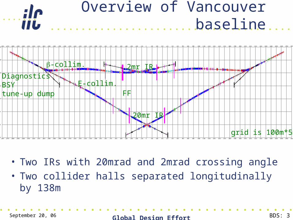
Overview of Vancouver baseline
• Two IRs with 20mrad and 2mrad crossing angle• Two collider halls separated longitudinally by 138m
20mr IR
2mr IR
FFE-collim.
-collim.
DiagnosticsBSYtune-up dump
grid is 100m*5m

September 20, 06 Global Design Effort BDS: 4
• Evaluation is focused on the differences between 20mr and 2mr branches, and focused on – study of physics reach– background conditions in IR – radiation conditions in extraction lines– performance of downstream diagnostics– technical feasibility of magnets– power consumption and cost
• Next, flash through some examples of such comparisons, presented at Vancouver
Evaluation of baseline before Vancouver

September 20, 06 Global Design Effort BDS: 5
100W/m hands-on limit
Losses are mostly due to SR. Beam loss is very small
100W/m
Losses are due to SR and beam loss
20mrad
2mrad
Losses in extraction line20mr: losses < 100W/m at 500GeV CM and 1TeV CM
2mr: losses are at 100W/m level for 500GeV CM and exceed this level at 1TeV
Radiation conditions and shielding to be studied
250GeV Nominal, 0nm offset
45.8kW integr. loss

September 20, 06 Global Design Effort BDS: 6
Study of SUSY reach• Reaction which cares most about crossing angle is• Main background is due to copious two photon processes
which require low angle tagging• Tagging is challenged by pairs background and presence of exit hole
• SUSY reach is challenged for the large crossing angle when m (slepton-neutralino) is small
• Studies presented at Bangalore (V.Drugakov) show that for 20mrad+DID (effectively ~40mrad for outgoing pairs), due to larger pairs background, one cannot detect SUSY dark matter if m=5GeV
• The cases of 20 or 14mrad with anti-DID have same pairs background as 2mrad. Presence of exit hole affects detection efficiency slightly. The SUSY discovery reach may be very similar in these configurations
• Several groups are studying the SUSY reach, results may be available after Vancouver

September 20, 06 Global Design Effort BDS: 7
Brainstorm to design magnets in 2mrad extraction
Some magnet sizes on this drawing are tentative
> 2
m BHEX1
low field B1
Recent suggestions by magnet tech group
Magnet group to CCB after Vancouver: “…there is still work that could be done to improve them further … but that by the nature of their aperture requirements and relative beamline spacing which arises naturally in the 2 mr layout, they will always be very challenging magnets that many experienced magnet designers place at the cusp of feasibility.”
September 20, 06 Global Design Effort BDS: 8
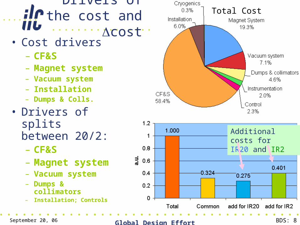
Drivers of the cost and cost
• Cost drivers– CF&S– Magnet system– Vacuum system– Installation– Dumps & Colls.
• Drivers of splits between 20/2:– CF&S– Magnet system– Vacuum system– Dumps &
collimators– Installation; Controls
Total Cost
Additional costs for IR20 and IR2

September 20, 06 Global Design Effort BDS: 9
Vacuum, Dumps & collimators: BDS 20/2
Chambers of longer 2mr extraction line and additional chamber for beamstrahlung photons cause the cost difference
Larger number of collimators in 2mrad extraction line and additional photon dump cause the difference

September 20, 06 Global Design Effort BDS: 10
Magnet system: BDS 20/2
Larger number of huge extraction line magnets, and its power supplies (PS) cause the cost difference

September 20, 06 Global Design Effort BDS: 11
CF&S: BDS 20/2
The common fraction is quite large. The difference come from beam dump halls and mostly (~90%) from cooling water

September 20, 06 Global Design Effort BDS: 12
At Vancouver
• Discussion of 20/2 baseline situation – by BDS area leaders– with present colleagues from BDS group– with MDI panel (plus those connected remotely) – with WWS organizing committee– with EC and GDE director
• It was decided to cut the Gordian knot of the cost, technical and non-technical issues and propose to change the baseline to two IR with 14/14 configuration
– Design & cost of 14/14 with common collider hall & z=0• Design of 14mr beamline is almost the same as for 20mrad• In the 14/14 cost estimation, the following adjustments were estimated and
taken into account: removed stretches in optics; shorter (~11mr/14mr) tapered tunnels; remove one surface building; savings due to common hall (but volume still twice the single volume); add cost of 42% more gradient bends (for 14mrad bend), their PS, BPMs, movers, etc
• The two IR config with 14mrad in both IRs reduces the cost by 15.6%

September 20, 06 Global Design Effort BDS: 13
After Vancouver: submission of CCR, evaluation by WWS, MDI and CCB
• CCR (Class 2) for 14/14 configuration submitted on July 28• MDI panel meeting on Aug. 15 (link to agenda), to discuss
– 14/14 configuration– single collider hall– on-surface detector assembly– 5m muon spoilers instead of 9m+18m
• The MDI panel accepted those changes. The conclusions were sent to WWS and CCB. (Link to MDI panel minutes)
• The WWS OC was asked to comment about the first two items and also accepted them
• CCB considered the CCR for 14/14, and on September 8 issued a recommendation for EC to adopt the CCR as is
• CCB noted that it was the first Class-2 request and part of the time was spent on nailing down the protocols for cost information handling
<= CCR submitted on July 28
<= CCR in preparation
<=CCR submitted on Sept. 8

September 20, 06 Global Design Effort BDS: 14
From minutes of MDI panel (shortened quote)
• The (physics) mode most affected by crossing angle is the slepton pair production where the slepton-LSP m is small. The main background is 2- processes and an efficient low-angle electron tag by BEAMCAL is needed to veto them.
• Difference in expected background (is due to) different levels of veto efficiency. Signal to noise will be ~4 to 1 with 2mrad crossing angle.
• For a large crossing angle (14 or 20mrad), anti-DID is needed to collimate the pair background along the outgoing beam. For 14mrad crossing with anti-DID, the … background is expected to be comparable to the 2mrad case while the signal efficiency reduces by about 30% to 40%. This is mainly due to the 2nd hole of BEAMCAL that is needed for the large crossing angle which will force additional cuts to remove the 2-photon and other backgrounds.
• This is not based on a complete analysis but on a study of the pair background distribution on the BEAMCAL: that for 20mrad crossing with anti-DID was found to be essentially the same as the 2mrad case. A complete analysis is needed for 14mrad with anti-DID, also covering different values of the mass difference (namely, for different SUSY parameter space). Backgrounds considered here is mainly the pair background and a lesser extent Bhabha events. More studies are sorely needed in this area.
• With this limited information, the MDI panel thinks that the 14mrad is acceptable as the baseline at this time. However, we would like to stress that the 2mrad crossing angle is clearly desirable than larger crossing angles for the slepton search, and R&Ds related to 2mrad should be encouraged.
* LSP= lightest super-symmetric particle

September 20, 06 Global Design Effort BDS: 15
Tentative layout of 14/14 configuration
Common IR hall ~100m (L) x 30m (W) at z=0 with 28.4m X• 15m shafts equipped with elevator and stairs in IR hall • 4m tunnels in all BDS • Alcoves 4*6m every 100m, no service tunnel• Halls for dump cooling system 35*20m • Small 0.8m shaft for lasers near laser wire, upstream and downstream diagnostics• Long muon walls (9m & 18m) replaced by single 5m wall •Passages near muon walls (main and spare one)• 9m machine access shaft in the “BDS triangle”•Shortened extraction line•Shorter tapered tunnels. Etc.

September 20, 06 Global Design Effort BDS: 16
Further work baseline cost
• Optimizing the IR hall requirement and detector assembly procedure– considering pure-CMS and modified CMS
approached
• Optimizing CF&S design• Working on installation model and refining the
cost• Reviewing systems for possible cost
reductions• Discussing other possible cost saving
strategies

September 20, 06 Global Design Effort BDS: 17
Summary
• The process of change of baseline from 20/2 to 14/14, briefly outlined in this talk, included– Development of baseline design – Evaluation of backgrounds & physics reach– Study of beamline conditions & operability– Engineering evaluation of the design– Comparison of cost and operational expenses– CCR for change of baseline– Evaluation by WWS & CCB– Further optimization of new baseline

September 20, 06 Global Design Effort BDS: 18
END

September 20, 06 Global Design Effort BDS: 19
Backup slides
• Several slides related to – estimated error of cost– CCR on muon walls (submitted)– CCR for on-surface detector assembly– Some other example of comparative studies

September 20, 06 Global Design Effort BDS: 20
Estimated errors on cost 20/2 vs 14/14
• Estimated errors of cost
• It is unlikely that the errors in different systems are correlated, but if they are, we get
cost +error -errortotal initial 15.6%vacuum +1.4% -0.7%D&C +1.0% -0.5%Magnet +1.7% -0.6%CF&S water +0.1% -2.5%CF&S other +2.0% -0.1%
cost = 15.6% +6.2% -4.4%

September 20, 06 Global Design Effort BDS: 21
Muon walls
Baseline configuration:18m and 9m walls in each beamline
Scheme of a muon wall installed in a tunnel widening which provide passage around the wall
• Purpose:– Personnel Protection: Limit
dose rates in one IR what beam sent to other IR or to the tune-up beam dump
– Physics: Reduce the muon background in the detectors

September 20, 06 Global Design Effort BDS: 22
Muon walls CCR
• Baseline config (18m+9m walls) reduce muon flux to < 10muons/200bunches if 0.1% of the beam is collimated
• Considered that – The estimation of 0.1% beam halo population is conservative and
such high amount is not supported by any simulations– The min muon wall required for personnel protection is 5m– Detector can tolerate higher muon flux. With single 5m wall there
is ~400muon/200bunches (500 GeV CM, 0.1% of the beam collimated) which corresponds to ~0.15% occupancy of TPC
– Cost of long muon spoilers is substantial, dominated by material cost and thus approximately proportional to the muon wall length
• Suggested CCR to install initially only 5m single walls– The caverns will be built for full length walls, allowing upgrade if
higher muons flux would be measured– Such upgrade could be done in ~3month
• MDI panel accepted this change

September 20, 06 Global Design Effort BDS: 23
CMS detector assembly approach:• Assembled on the surface in parallel with underground work•Allows pre-commissioning before lowering• Lowering using dedicated heavy lifting equipment• Allows saving up to 3years of time• Reduce size of underground hall required
• Accepted by MDI panel for ILC

September 20, 06 Global Design Effort BDS: 24
On-surface (a la CMS) assembly
• According to tentative CF&S schedule, the detector hall is ready for detector assembly after 4y11m after project start
• If so, cannot fit into the goal of “7years until first beam” and “8years until physics run”
• Surface assembly allows to save 2-2.5 years and allows to fit into this goal
• The collider hall size is also smaller in this case– A building on surface is needed, but savings are
still substantial

September 20, 06 Global Design Effort BDS: 25
On-surface detector assembly
Underground detector assembly
VERY TENTATIVE
start date arbitrary

September 20, 06 Global Design Effort BDS: 26
Backscattering of SR
FD produce SR and part will hit BYCHICMB surfaceTotal Power = 2.5 kW<E>=11MeV (for 250GeV/beam)
Takashi MaruyamaFrom BYCHICB
Rate #s at IP/BX
#s in SiTracker from pairs
250 GeV 1.1x10⁻⁸ 2200 700
500 GeV 2.9x10⁻⁸ 11700 1900
Photon flux within 2 cm BeamCal aperture:
SR from 250 GeV disrupted beam, GEANT
Flux is 3-6 times larger than from pairs. More studies & optimization needed

September 20, 06 Global Design Effort BDS: 27
Downstream diagnostics evaluation
Comparisons for 250GeV/beam 20mr 2mr
Beam overlap with 100mm laser spot at Compton IP
48% 15%
Polarization projection at Compton IP 99.85% 99.85%
Beam loss form IP to Compton IP <1E-7 >2.6E-4
Beam SR energy loss from IP to middle of energy chicane
119MeV 854MeV
Variation of SR energy loss due to 200nm X offset at IP
< 5MeV
( < 20 ppm)
25.7MeV
(~100 ppm)
The need for SR collimator at the Cherenkov detector
yes No
comparable with the goal for E precision measurements