separation of oxygen from seawater by ... co co 00 sdaaa c-0414 separation of oxygen from seawater...
TRANSCRIPT

00*
COCO00
SDAAA C-0414
SEPARATION OF OXYGEN FROM SEAWATER BY MEMBRANE PERMEATION
C.-M. Bell, P. Chow and R.W. BakerMembrane Technology and Research. Inc.Mealo Park, CA 94025
March 1989
FINAL TECHNICAL REPORTFor Period 31 August - 28 February 1989
Approved for public release; distribution is unlimitad.
Prepared for.DARPAResearch, Development and Engineering CenterRedstone Arreaal, AL 35898
Contract DAAHD1-88-C-0414 D TICELECTEJUN06 1989 U
89 6 05 018

SECURItY CLAMSIICAtION OF THIS$ PAGE
REPORT DOCUMENTATION PAG~EIa. REPORT SECURITY CLASSIFICATION lb. RESTRICTIVE MARKINGS
UNCLASSIFIED _______________________
2a SECURITY CLASSIFICATION AUTHORITY 3. DISTRIBUTION I AVAILABILITY OF REPORT
Approved for Public Release-2b. DECLASSIFICATION / DOWNGRADING SCHEDULE Dis tributi~on is Unlimited
4, PERFORMING ORGANIZATION REPORT NUMBER(S) S. MONITORING ORGANIZATION REPORT NUMBER(S)
DAAH01-88-C-0414 DAAHO1-88-C-04 14
6a. NAME OF PERFORMING ORGANIZATION 6b. OFFICE SYMBOL 7a. NAME OF MONITORING ORGANIZATIONMembrane Technology and (if appiicable) DCASMA, San FranciscoResearch, Inc.I
6.- ADDRESS (City. State. and ZIP Code) 7b. ADDRESS (City. State, and ZIP Code)1360 Willow Road, Suite 103 1250 Bayhill. DriveMenlo Park, CA 114025 San Brur.-, CA 94066-3070
B&. NAME OF FUNDING, SPONIORINC, 8 b. OFFICE SYMBOL 9. PROCUREMENT INSTRUMENT IFENtIFICATION NUMNEIE
ORGAEJIZt TION O (f appacabie)U.S. Arm,'M4 35ile Commiand DARPA __MA 1-8-C-0414 -
St. ADDRESS fCjMy Vat*. and ZIP Code) I0. SOURCE OF FUNDING NUMBERS
lAMSMI-RD-DP !DARPA Proj. Ofc., Blc~g. 7770 PROGRAM P'ROJECT TASK WORT' UNITRedstone Arsenal, AL -5898-5280 ]ELEMENT NO. ~NO. NO. ACCESSION NO.
'I. 1ITLE (Imdudl SO~ufltY 041JU&~rAN01 (Unclassified)Separation of Oxygen from Seawacer by Membrane Permeationi
12. PERSONAL AUTNO0R(S,%_____________C.-M. Bell and J.G. Wiimans ____ ____
13a. TYPE OF REPORT 13b. TIME COVERED 4.DATE OF REPORT (Yett. Moi'ta Day) AZCOUNTFINAI FROMI8/31/88 0IA8 April 1989
16. S!JPPLEMfNTARY NOTATION
17.COSATI CODES IS. SUSJ(CT TERMS jCont4%w on iwoe~w it twteiwy #nd 4ratity byi bkoik a.morh)FIELD GIROUP Sul-GROUP
i.ST&7(CoEmwU. on ovWtem # cwad eN*M byuI~ ~ blocit nMAinb.)<-.
~'Areliable method' tor extracting oxygen from Seawater it required for a number or naval*ppievibiva~s. This progrem dexcribe: the development of a membrane system to perform thisextraction.-teawater containing dissolved air is brought in contact with a suitabie mevabrane, andthe dissolved air preferentially permeates the membrane. to this Phase I program. two thin-filmcomposite membranes were evaluated. andjthe feasibility of the approach was demonrtrated using asmall bench-scale system fitted with a 6-msorc~sil-wound membrane module. Approximately 40% ofthe divielved oxygen in seawater could be removed in a single pass through the memfbraAn module.The oxygen concentration of the permeate gas was 33%.
A technical ansJysis was conducted for the application of this technology for ill lire supportan submarines, and J2) oxygen supply for submerged fuel cells. The analysis showed the fuel cellapplication to be the moss promising. to this application. the power consumption of the oxygenc.-trzclion process is 25% Of the energy produced by the fuel cell. '
10 OaITwlS*UT"!N*VA5j4IUTY Of AASTRACT 21t. ASS1RACT SECURITY CLASWS^IGATO
0 UMICIASSIFICIDAJNLUMITIEO 0 SAM( AS RDT. MX DT1C USERS 1Cut 1i355iif Id
22. E~iA OSF KE'SPONUSI~t ittVIOUALL 22costic6 $y"40L
00 FORM 1473. && vAs U3ANR"110.- 341 be ji4 untlt tthaugld %5gTVP1 (IA LVAVV ODF THiS -PACAJU kl oi'Id4soft at* obuflte.
NOTICE
"This -eport was prepared us an account of work sponsored by an agency oftiue United States Government. Neither the United States nor any agency thereof,nor any of i . ,mployees, nor any of its contractors, subcontractors, or theiremplo.-ees, make; 3ny warranty, expressed or implied, or assumes any legal!iability oi re,.,,oLsibility for any third party's use or the results of such use oftny !iformation, apparntv-, product or process disclosed in this report or
represents thL its use by such third party would not infringe privately ownedright's.
DISCLAIMERS
The citation of trade names and names of manufacturers in this report is notto be const,-ued as official Government endorsement or approval of commercialproducts or services referenced herein.
Destroy this report when it is no longer needed. Do not return it tooriginator.
Accession For
NTIS G.L"IITIC TABUnannounced 0
Distributioti/Availability Codos
3Avd t'l and/orlist Special

List of Figures
Figure 1. Schematic of pervaporation process .................. 2
Figure 2. Schematic of MTR composite membrane ............... 4
Figure 3. A spiral-wound membrane module. MTR producesmodules with membrane areas ranging from0.3 m2 for laboratory modules to 6 m2
commercial-sized modules ........ ................ 4
Figure 4. Schematic of experimental apparatus for measuringthe oxygen extraction rate from seawater bypervaporation ....... ....................... 7
Figure 5. Photograph of the experimental set-up for measuringthe oxygen extraction rate from water ................ 8
Figure 6. Composition of the permeate gas as a function of thefeed flow rate for two spiral-wound modules withdifferent permselective membrane materials ............. 10
Figure 7. Oxygen extraction rate per six-inch module as a functionof feed water flow rate at room temperature ............ 11
Figure 8. Oxygen removal as a function of feed water flow rateat room temperature ....... .................... 12
Figure 9. Pressure drop across pervaporation moduleas a function of feed water flow rate ................. 13
Figure 10. Concentration profile of dissolved gases (oxygen, nitrogenand carbon dioxide) in oxygen extraction experiments..... 16
Figure 1I. Two different system designs for an oxygen extractionsystem for fuel cell applications .................... 18
Figure 12. Conceptual design of an oxygen extraction system forlife support applications ........................ 21

List of Tables
Table 1. Permeation Properties of Spiral-Wound Modules used in OxygenExtraction Experiments ........ .................... 5
Table 2. Conditions During Oxygen Extraction Experiments .......... 6
Table 3. Oxygen Extraction Performance Data Obtained with aSpiral-Wound Membrane Module at Two Feed Flow Rates . . . 10
Table 4. Characteristic Features of the Oxygen ExtractionProcess in Comparison with a Standrrd Pt.-vaporationProcess. ......... ........................... 14
Table 5. System Design and Performance Requirements for MembraneSystem to Extract Oxygen from Seawater ..... ........... 17
Table 6. Comparison of Module and Power Requirements for ThreeOxygen Extraction Systems Delivering 10 L/min Pure Oxygen . 20
TABLE OF CONTENTS
I. INTRODUCTION AND SIGNIFICANCE OF THE PROBLEM ...... I
II. BACKGROUND ........................... IA. THE PERVAPORATION PROCESS ............... IB. MEMBRANE AND MODULE TECHNOLOGY ......... 3
III. PHASE I OBJECTIVES ........................ 5
IV. EXPERIMENTAL METHODS .................... 5A. MODULE PREPARATION. ......................... 5B. OXYGEN EXTRACTION EXPERIMENTS ........... 6
V. RESULTS AND DISCUSSION .................... 6A. OXYGEN EXTRACTION RESULTS .............. 6B. INTERPRETATION OF RESULTS ............... 14
VI. SYSTEM DESIGN AND ANALYSIS ................. 15A. OXYGEN FOR SUBMERGED FUEL CELLS .......... 17B. OXYGEN FOR LIFE SUPPORT ................. 20
VIII. CONCLUSIONS ........................... 22
REFERENCES . .............................. 22

I. INTRODUCTION AND SIGNIFICANCE OF THE PROBLEM
_:A reliable and compact system able to extract dissolved oxygen fromseawater is required for a number of naval applications. This proposal describesthe application of a membrane process called pervaporation to the problem of
-.ooxygen separation. Over the past four years, we have developed a pervaporation. . process tofr-ex-it-racting dissolved organic solvents from dilute aqueous feed streams.
With some modifications, the same membranes and membrane systems can be usedto extract oxygen from seawater. Seawater containing dissolved air is brought incontact with one side of a selective membrane. A partial vacuum is applied tothe other side of the membrane and this produces a flow of water vapor, oxygen,nitrogen and carbon dioxide across the membrane. The flow of each componentacross the membrane is determined by the partial pressure difference and thepermeability properties of the membrane. As will be shown in this report, it ispossible to operate the membrane such that only oxygen is extracted.
Two uses for the oxygen extracted from seawater have been examined. Thefirst application is the production of oxygen enriched air for submarine life-support systems. Currently, this oxygen is produced by electrolysis of water.The second application is the production of oxygen as an oxidant for a fuel cell.Fuel cells are used as power sources for submerged sensor stations. A water-oxygen circulation system would reduce the bulk and extend the lifetime of such asystem. The utility of a membrane system to these two applications is describedin more detail in Section VI of this report.
11. BACKGROUND
A. THE PERVAPORATION PROCESS
The theory of pervaporation has been described extensively in the literature.and will not be covered in detail here.1'- In essence, pervaporation is adiffusion-controlled membrane process, used to separate one or more volatiledissolved components from a liquid feed mixture. Water and dissolved gases orvapors permeate the membrane at a rate determined by their relative volatilitiesand their ability to permeate the membrane. The rate-controlling step is assumedto be diffusion through the membrane under a concentration gradient. Theoverall separation factor, P depends on the intrinsic selectivity of themembrane, defined as the ratio of the permeabilities of the components, and onthe partial pressure differences of the components on the feed and permeate sidesof the membrane. The full selectivity of the membrane is only uwilized when thepartial pressure difference is maximized. Thus, in order to get a good separationof components in a pervaporation process, it is important to use a membranematerial with high intrinsic selectivity for the compotents to be separated, and tooperate the system with the largest practical partial pressure difference throughthe membrane. The process in its simplest form is shown in Figure 1.
I
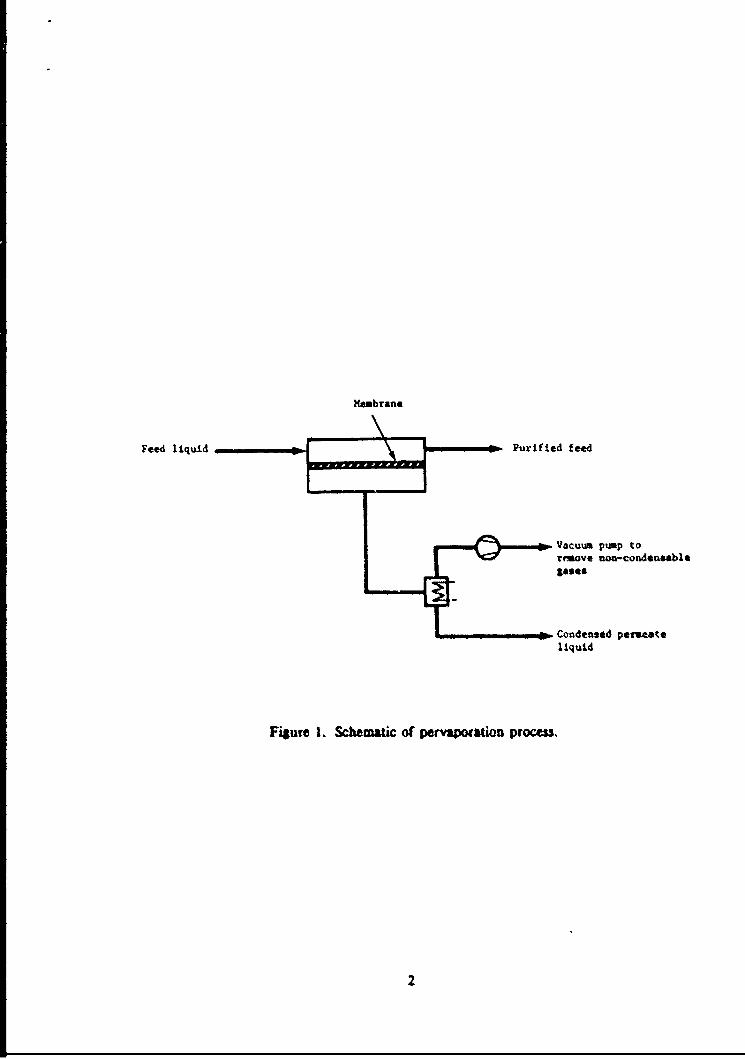
Membrane
Feed liquid Purified feed
Vacuu pimp tovr~eove non-condensable
Condensed permeateliquid
Fisufe I. Schameac of Perv&Wtion Vrocess.
2

In a practical system, a liquid mixture contacts one side of a membrane andthe permeate is removed as a vapor from the other side. Transport through themembrane is induced by maintaii.ing the partial vapor pressure on the permeateside lower than the partial pretiure on the liquid side. This partial pressuredifference can be achieved in several ways, most economically by cooling thepermeate vapor, causing it to condense. Condensation of the permeate vaporspontaneously generates the permeate vacuum required. Pervaporation units areequipped with small vpcuum pumps to remove noncondensable gases (primarilydissolved air).
In this pervaporation process the desired product is the nonconden.-able gasoxygen. The amount of dissolved oxygen in water is actually very low: 8-7 ppmby weight, if the water is fully saturated with air. This low oxygenconcentration substantially affects the performance of the process. Mostimportantly, the water feed flow rate to the membrane system has to be large inorder to provide enough oxygen to be extracted. Thus, the feed flow rates usedin the extraction process will be much larger than those normally encountered inpervaporation applications.
B. MEMBRANE AND MODULE TECHNOLOGY
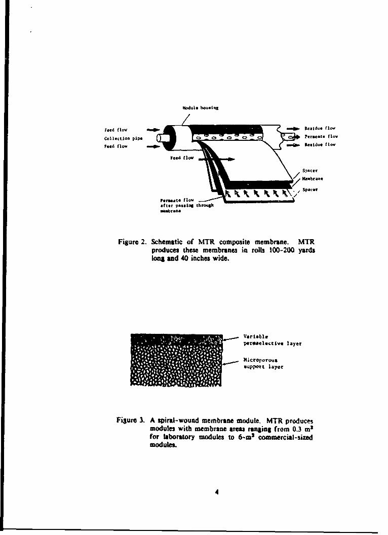
The heart of MTR's pervaporation separation technology is our ability toproduce high flux, high selectivity, multilayer polymer membranes. Themultilayer membrane structure consists of a tough, open microporous polymerlayer that provides strength, and an ultrathin dense polymer coating that isresponsible for the separation properties. The MTR composite membrane structureis shown schematically in Figure 2. Over the past six years, the company hasdeveloped the technology to produce these membranes defect-free, in rolls 40inches wide and 100-200 yards long. The membranes have been tested at pressuredifferences up to 500 psi; and proved to be stable. The anticipated maximumoperating pressure for oxygen extraction systems is expected to be well over500 psi;. Thus, in an eventual follow-on program, the membrane will have to betested at higher pressures. Membrane stability at the higher pressures is notexpected to be a problem, however.
The composite membranes are fabricated into spiral-wound modules of thetype illustrated in Figure 3. In operation, feed liquid enters the module and flowsbetween the membrane leaves. The organic solvenm components of the feed, aswell as dissolved air, go through the membrane more readily than %ater. Thefraction of the feed that toes through the membrane spirals inward to a centralpermeate collection pipe. The rentainder of the feed flows across the membranesurface and exits as the residue. These membrane modules can be conaected in aserial or parallel flow arrangements to meet the capacity and separationrequirements of any particular separation.
3
modul. housing
Feed flow OMIN •-• . Residue flow
Collection Ppe c., Permeate flow
feed flow 19 =9 Ridue flowFeed flow /•Ste
nMebran*
Ofter passing thr'ougqh
Figure 2. Schematic of MTR composite membrane. MTRproduces these membranes in rols 100-200 yardslong and 40 inches wide.
Variableparogelectivt layer
x1creporotu
tupport layer
Fisure 3. A spiral-wound membrane module. MTR productsmodules with membrane aream ranginl from 0.3 m3for laboratory modules to 6-m3 commercial-sizedmodules.
4
III. PHASE I OBJECTIVES,
The overall goal of this program was to demonstrate the feasibility of usingpervaporation to remove dissolved oxygen from seawater. Specific tasks involvedbuilding and operating a laboratory-scale test unit and using the experimentalresults obtained with this unit in a preliminary system analysis aimed at twoapplicatioas (a) oxygen for fuel cells, and (2) oxygen for life support.
IV. EXPERIMENTAL METHODS
A. MODULE PREPARATION
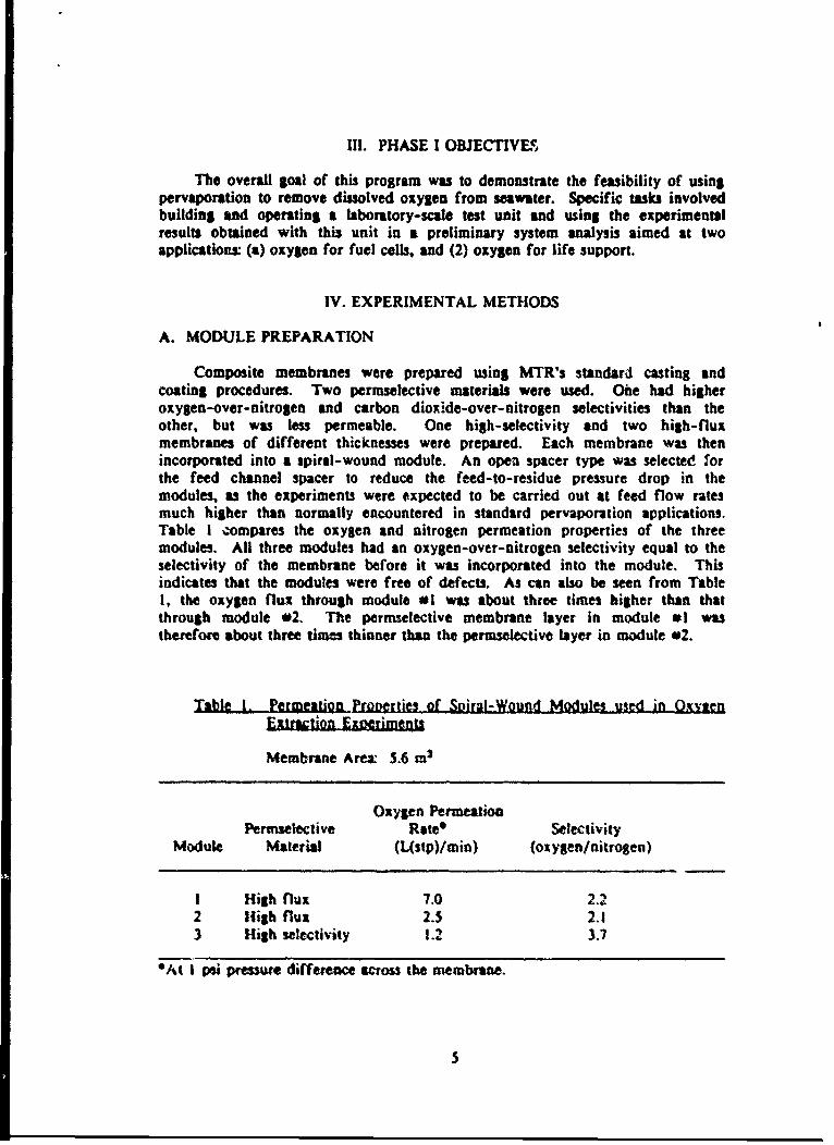
Composite membranes were prepared using MTR's standard casting andcoating procedures. Two permselective materials were used. One had higheroxygen-over-nitrogen and carbon dioxide-over-nitrogen selectivities than theother, but was less permeable. One high-selectivity and two high-fluxmembranes of different thicknesses were prepared. Each membrane was thenincorporated into a spiral-wound module. An open spacer type was selected forthe feed channel spacer to reduce the feed-to-residue pressure drop in themodules, as the experiments were expected to be carried out at feed flow ratesmuch higher than normally encountered in standard pervaporation applications.Table I compares the oxygen and nitrogen permeation properties of the threemodules. All three modules had an oxygen-over-nitrogen selectivity equal to theselectivity of the membrane before it was incorporated into the module. Thisindicates that the modules were free of defects. As can also be seen from Table1. the oxygen flux through module #1 was about three times higher than thatthrough module 02. The permselective membrane layer in module *I wastherefore about three times thinner than the permeective layer in module 02.
Table I. Permeation Pronerties of Spirml-Wound Modules used ifn OxQtenExtraction Eoerimenqt
Membrane Are. 5.6 m2
Oxygen PermeationPermsetective Rate* Selectivity
Module Material (L(stp)/min) (oxygen/nitrogen)
I High flux 7.0 2.22 High flut 2.5 2.13 High selectivity 1.2 3.7
*At I psi preure difference across the membrane.
5
B. OXYGEN EXTRACTION EXPERIMENTS
The experimental apparatus for measuring the oxygen extraction rate fromwater is shown in Figure 4. A photograph of the system ;s shown in Figure 5.The feedwater was continuously aerated with atmospheric air to saturate thewater with oxygen, nitrogen and carbon dioxide. The water was pumped througha filter to remove air bubbles, and then passed through the membrane module.The residue stream exiting the module was returned to the tank. Flow throughthe membrane was achieved by maintaining a reduced pressure on the permeateside of the membrane. The water vapor in the permeate stream was condensed inthe cooler and the noncondensable gases, i.e., oxygen, nitrogen and carbondioxide, were removed via the vacuum pump. The composition of the gas streamexiting the vacuum pump was analyzed with a gas chromatograph. The dissolvedoxygen concentration in the feed and residue streams was measured with adissolved oxygen meter. In all experiments, good agreement was found betweenthe amounts of oxygen removed from the water and the amount of oxygen presentin the permeate gas stream.
For simplicity, experiments were carried out using regular tap water. Forsome experiments we used an artificial seawater mixture, prepared by adding apowder, "Instant Ocean' (Aquarium Systems, Mentor, OH), to the tap water. Theadded salts slightly changed the equilibrium concentrations of oxygen, nitrogenand carbon dioxide in water. However, because the salts are nonvolatile, theydid not permeate the membrane.
V. RESULTS AND DISCUSSION
A. OXYGEN EXTRACTION RESULTS
Oxygen extraction experiments were carried out with three modulescontaining three different membranes: (i) a high-flux thin membrane, (2) a high-flux, thicker membrane, and (3) a high-selectivity membrane. All experimentswere carried out using the apparatus described above, and the operatingconditions given in Table 2. The feed flow rate was varied over the range 1-20gallorts per minute (gpm). These are higher flow rates than are typically usedwith pervaporation systems for standard applications, which normally operate at0.5 to 5 gpm feed flow rate per individual module.
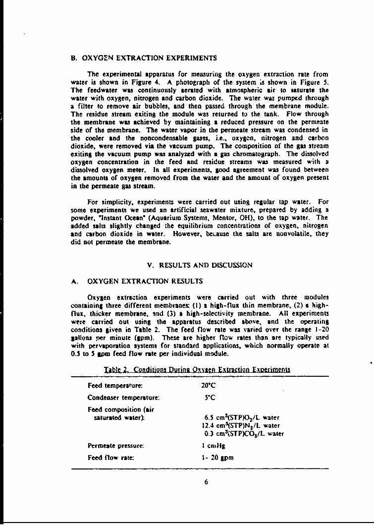
TkIle 2, Codiiopns During Qsvifen Extraction Eweriments
Feed temperature: 201(:C
Condenser temperature: 59C
Feed composition (airsaturated waterr) 6.5 cmNSTP)O5/L water
12.4 cmNOSTP)NSiL water0.3 cm3(STP)CO2/L water
Permeate premure: I cnailg
Feed flow rate: I - 20 gpm
6
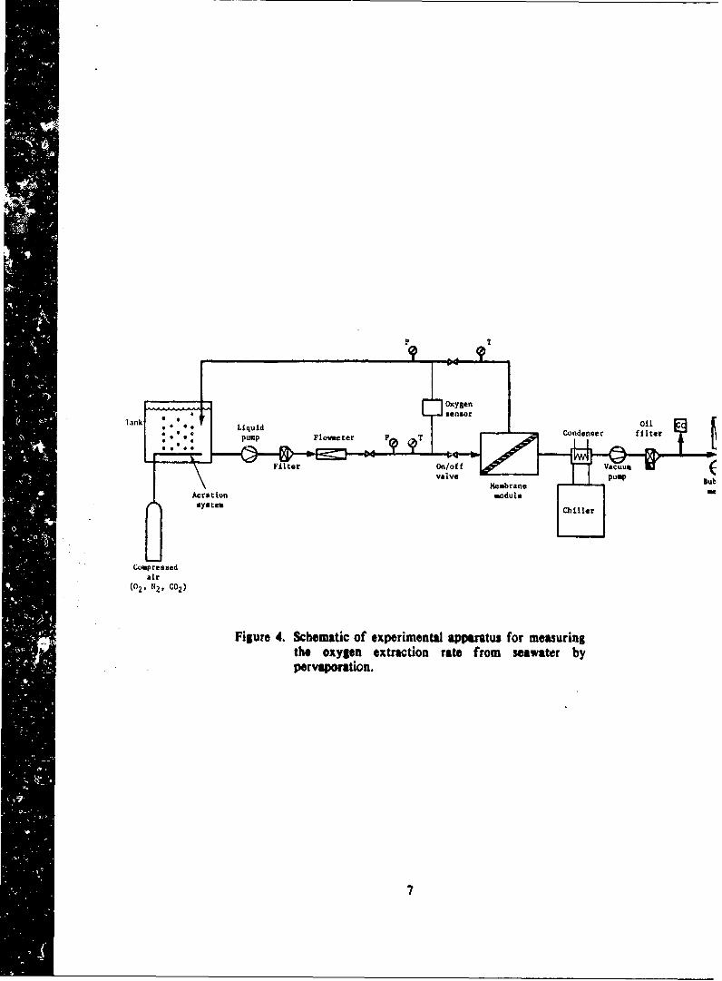
Tank I* oil* LiquidFoeee Condenser filter
FitrOn/off Vcuum(valve Pump
MembraneBume io odul 4
Compressedair
(02. NZ, C02)
Figure 4. Schematic of experimental apparatus for measuringthe oxygen extraction rate from seawater by"pervaftifn.
7

Figlure 5. Photograph of the exPerimeMAl Set-UP (fo
measur'4 the oxygen extractionl rate L~or~a water,
8

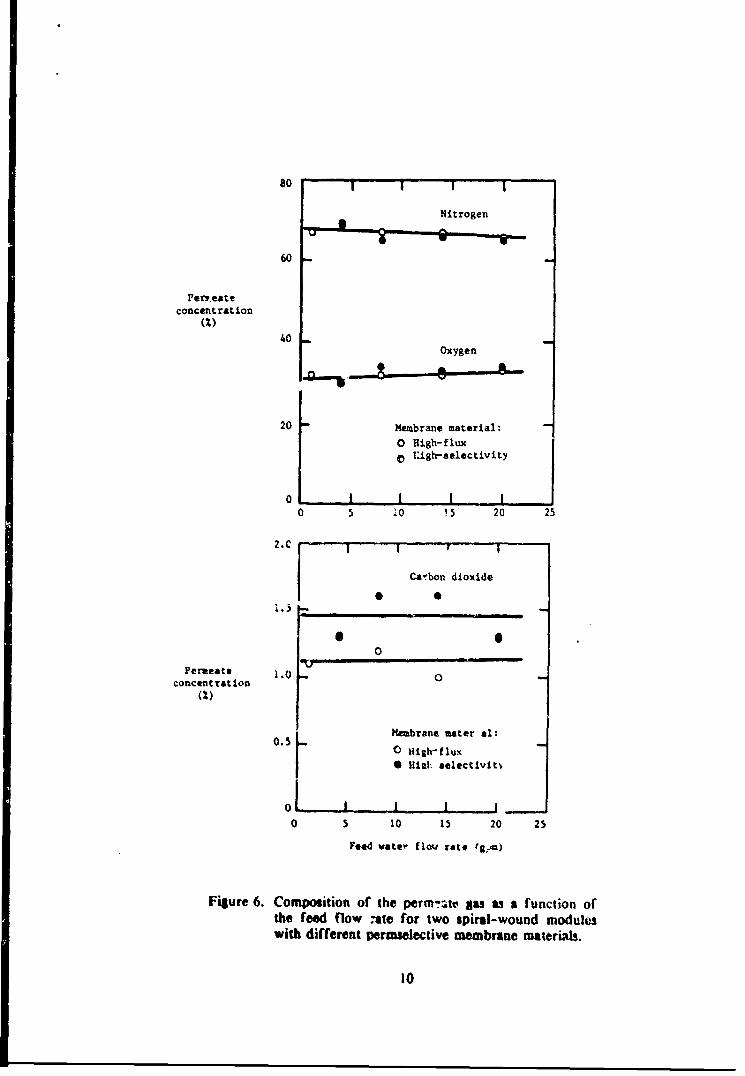
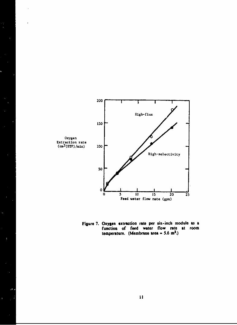
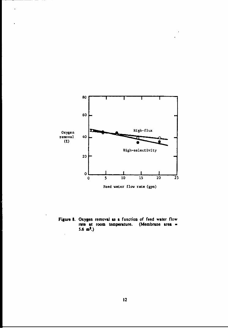
The modules were able to ext-act approximately 40% of the gas dissolved inthe feed, producing a permeate stream of oxygen-enriched air at a rate of 130-450 cmra/min. The results are shown in more detail in Figures 6. 7 and 8. Figure6 shows the composition of the permeate gas as a function of the feed flow ratefor module #1, the higher-flux module and module #3, tle high-selectivity module.Data for module #2 containing the thicker membrane are not shown. However,modules #1 and #2 gave essentially identical resu.ts. The comprosition of thepermeate gas was the same for all these modules and was independent of the feedwater flow. The permeate gas composition (33% 02, 66% N2 and 1.3% C0 2 )closely resembles the composition of air dissolved in water (see Table 2).
The oxygen permeate flow rpte is shown as a function of the feed flowrate in Figure 7. The oxygen extraction rate is roughly proportional to the feedflow rate and is the same for modules #1 and #2, even though the membrane inmodule #2 is about three times less permeable than the membrane in module #1.The oxygen permeate flow rate measured for module #3 is about 25% lower thanthat obtaintd with the other two modules. Figure 8 gives the oxygen removalfrom #he feed stream as a function of the feed flow rate. Oxygen removal isdefined as the oercentage of the oxygen present in the feed stream that isremoved from the feed stream via the membrane. Figure 8 shows that the oxygenremoval decreases slightly with increasing feed flow rate, and that the amount ofoxygen removed is independent of the membrane type used.
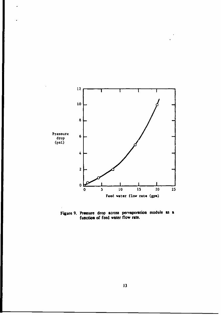
Based on the results shown above, it appears the air production rate can beincreased by increasing the feed water flow rate. However, increasing the feedwater flow rate requires a greater pressure to force the water through themodudes. We therefore measured the feed-to-residue pressure drop as a functionof feed water flow rate. The results are shown in Figure 9. From these data,the energy requirement per cm3(STP) oxygen produced can be calculated as afunction of feed flow rate.
The data shown in Figure 7 and 8 were obtained with oxygenated tap water.A few compeartive experiments were performed with artificial seawater. Table 3summarizes the results, incW-ding those obtained with the artificial seawatermixture. The oxygen extraction rate is 10 to 15% lower in the case of seawaterbecause saline water has a lower solubility for gases than pure water. Table 3also shows that the extracted amount of potable water is independent of themotulo feed flow rate.
Table 3. Oxvyen Extraction Performance Data Obtained with a Sniral-WoundMeMbrane Module at Two Feed Flow Rates
Permeate Module Feed Flow RateFlow Rate (I gpm) (20 Spm)
Tap water Seawater Tap witer Seawater
Oxygen (L/h) 0.66 0.58 II 9.2Air (L/h) 22 19 36 30.6Water (g/h) 0.4 0.4 0.4 0.4
9
so
Nitrogen
60
Per.eate
concentration(2)
40Oxygen
20 Membrane material:
o High-fluxSEigh-selectivity
0 .5 0 15 20 25
2. * T--. I I-
Ca'bon dioxide
* S0
Permeate 1.O 0concentration
(2)
Membrane aster alio (lHigh-
flux
0 HUiEl selectivity
0 5 t0 15 20 25
Feed vater flw rate (gr.a)
Figure 6. Composition of the perm,!2tv gas as a function ofthe feed flow -ate for two spiral-wound moduleswith different permselective membrane materials.
10
200 1 1 1 I
High-flux
150 -
OxygenExtraction rate(cm3 (STP)/min) 100
High-selectivity
50
0 I I I0 5 10 15 20 25
Feed voter flow rate (gpm)
Figure 7. Oxygen extraction rate per six-inch module as afunction of feed water flow rate at roomtemperature. (Membranue area - 5.6 ms.)
11
80
60
Oxygen High-flux
removal 40 ~ ~ ~ f u(z)
High-selectivity
20-
0 I I I I0 5 10 15 20 25
Feed water flow rate (gpm)
Figure 8. Oxygen removal a3 a function of feed water flowrate at room temperature. (Membrane area -5.6 m2.)
12
12
10
Pressure 6drop
(psi)
4
2
00 5 10 15 20 25
Feed water flov rate (gpm)
Figure 9. Presure drop across pervaporation module as afunction of feed water flow rate.
13
B. INTERPRETATION OF RESULTS
The module experiments showed that the permeate gas composition, and theoxygen removal from the feed achieved by the membrane system, were bothindependent of the nature of the membrane, and essentially independent of thefeed flow rate. The permeate gas flow rate was found to be proportional to thefeed flow rate. These results are in sharp contrast to those normally expectedfrom a pervaporation system. The differences are c,-!c!d by the very lowconcentration of dissolved oxygen in seawater, which produced a boundary layerresistance next to the membrane surface. The effect of this boundary layer onoxygen extraction from seawater can be understood with reference to Table 4,which lists five features determined experimentally in the oxygen extractionexperiments and five corresponding features of a standard pervaporation process.
Table 4. Characteristic Features of the Oxvaen Extraction Process in Comparisonwith a Standard Pervaooration Process
Oxygen Extraction Pervaporation(oxygen from water) (organic from water)
Permeate composition independent of Permeate composition depends onmembrane properties membrane properties
Permeate flow rate independent of Permeate flow rate depends onmembrane properties membrane properties
Permeate composition independent of Permeate composition depends onof feed flow rate feed flow rate
Permeate flow rate of preferentially Permeate flow rate of preferentiallypermeating component (oxygen) permeating component (organic)proportional to feed flow rate increases slightly with feed flow
rate
Percentage of preferentially permeating Percentage of preferentiallycomponent (oxygen) removed from the permeating component (organic)feed minimally dependent on feed removed from the feed decreasesflow rate markedly with feed flow rate
14
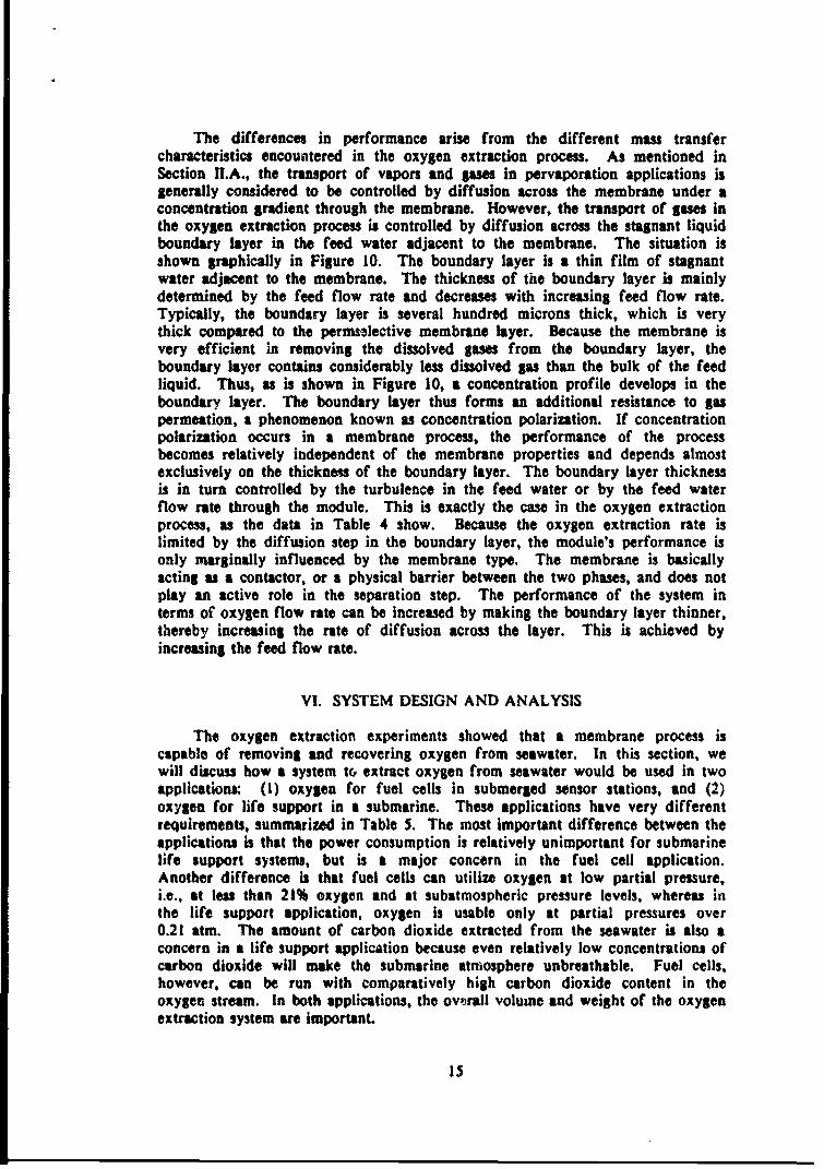
The differences in performance arise from the different mass transfercharacteristics encountered in the oxygen extraction process. As mentioned inSection II.A., the transport of vapors and Sas in pervaporation applications isgenerally considered to be controlled by diffusion across the membrane under aconcentration gradient through the membrane. However, the transport of gases inthe oxygen extraction process is controlled by diffusion across the stagnant liquidboundary layer in the feed water adjacent to the membrane. The situation isshown graphically in Figure 10. The boundary layer is a thin film of stagnantwater adjacent to the membrane. The thickness of the boundary layer is mainlydetermined by the feed flow rate and decreases with increasing feed flow rate.Typically, the boundary layer is several hundred microns thick, which is verythick compared to the permselective membrane layer. Because the membrane isvery efficient in removing the dissolved gases from the boundary layer, theboundary layer contains considerably less dissolved gas than the bulk of the feedliquid. Thus, as is shown in Figure 10, a concentration profile develops in theboundary layer. The boundary layer thus forms an additional resistance to gaspermeation, a phenomenon known as concentration polarization. If concentrationpolarization occurs in a membrane process, the performance of the processbecomes relatively independent of the membrane properties and depends almostexclusively on the thickness of the boundary layer. The boundary layer thicknessis in turn controlled by the turbulence in the feed water or by the feed waterflow rate through the module. This is exactly the case in the oxygen extractionprocess, as the data in Table 4 show. Because the oxygen extraction rate islimited by the diffusion step in the boundary layer, the module's performance isonly marginally influenced by the membrane type. The membrane is basicallyacting as a contactor, or a physical barrier between the two phases, and does notplay an active role in the separation step. The performance of the system interms of oxygen flow rate can be increased by making the boundary layer thinner,thereby increasing the rate of diffusion across the layer. This is achieved byincreasing the feed flow rate.
VI. SYSTEM DESIGN AND ANALYSIS
The oxygen extraction experiments showed that a membrane process iscapable of removing and recovering oxygen from seawater. In this section, wewill discuss how a system to extract oxygen from seawater would be used in twoapplications: (1) oxygen for fuel cells in submerged sensor stations, and (2)oxygen for life support in a submarine. These applications have very differentrequirements, summarized in Table 5. The most Important difference between theapplications is that the power consumption is relatively unimportant for submarinelife support systems, but is a major concern in the fuel cell application.Another difference is that fuel cells can utilize oxygen at low partial pressure,i.e., at less than 21% oxygen and at subatmospheric pressure levels, whereas inthe life support application, oxygen is usable only at partial pressures over0.21 atm. The amount of carbon dioxide extracted from the seawater is also aconcern in a life support application because even relatively low concentrations ofcarbon dioxide will make the submarine atmosphere unbreathable. Fuel cells,however, can be run with comparatively high carbon dioxide content in theoxygen stream. In both applications, the ovjrall volume and weight of the oxygenextraction system are important.
15

FEED MEMBRANE PERMEATE
I II SI I
I
Gasconcentration
BulkMicroporous
/ osupport
Boundarylayer
Permselect lyelayer
Figure 10. Concentration profile of dissolved gases (oxygen,nitrogen and carbon dioxide) In oxygenextraction experiments.
16

Table 5. System Desimn and Performance Reouirements for MembraneSystem to Extract Oxvaen from Seawater
Life SubmergedSystem Desian Parameters Supprt Fuel Cell
Volume + weight important -
Power consumption importantNoise important important
System Performance
Required oxygen concentration >20% preferably>10%
Permeate carbon dioxideconcentration important
Permeate pressure of permeategas mixture important
A preliminary system design analysis was performed for the two applications.The fuel cell application is promising. The oxygen for life support application isless promising, although possibly still feasible. A discussion of both applicationsfollow3.
A. OXYGEN FOR SUBMERGED FUEL CELLS
Submerged sensor stations require a power source which will continuouslydeliver I to 2 kW for several hundred days without any maintenance. Fuel cellsare capable of meeting these requirements. The fuel is hydrogen, which is storedin the station as pressurized hydrogen or a metal hydride. The oxidizer isoxygen, which can be stored in the station, but preferably will be extracted fromthe surrounding seawater. A I to 2 kW fuel cell will need 5 to 10 liters perminute of pure oxygen.4 In this section, we describe an oxygen eitraction systemcapable of generating 10 liters of oxygen per minute, to supply a fuel cellproducing 2 kW.
Two possible oxygen extraction system designs are illustrated in Figure iI.The vacuum-mode system shown in Figure I1(a) resembles the experimental set-upused in this program. In the vacuum-mode system, a vacuum pump is used tomaintain the oxygen partial pressure in the permeate gas under the equilibriumpressure of the oxygen dissolved in the seawater. Nitrogen and carbon dioxide.which permeate the membrane along with the oxygen, must be disposed of andthis would be done by compressing these gases to the hydrostatic pressure of theseawater and venting them. The power required for the compression step couldbe substantial and would be detrimental to the energy efficiency of the fuel cell.
17

Air-saturated 0Ardpaeseawater
seatate
sCondense (a)ere
*xtncVacuu Fysee C02 velneltpliaios
II
A second system, which we call a sweep-mode system, eliminates the need tovent gases, as well as the need for a vacuum pump. In this system, shown inFigure 11(b), a gas stream consisting of oxygen, nitrogen and carbon dioxide iscontinuously recirculated between the fuel cell and the permeate side of themembrane. The fuel cell consumes oxygen, thus lowering the oxygen content inthe recirculation stream. The difference in oxygen partial pressure between therecirculated gas and the oxygen in the seawater feed produces a flow of oxygenacross the membrane into the recirculation stream. A steady state will bereached when the amount of oxygen permeating the membrane is equal to theamount of oxygen consumed by the fuel cell. A similar steady state for nitrogenand carbon dioxide means that no nitrogen and no carbon dioxide will permeatethe membrane. The steady-state total pressure of the sweep stream will typicallybe under 76 cmHj, and is 66.7 cmllg, for example, in Figure I l(b).
The power demands of the extraction system operating in sweep mode aremainly determined by the energy needed to pump the seawater through themembrane modules. The lower the seawater flow rate per module, the lesshorsepower will be required. However, as was shown in Section V, the amount ofoxygen extracted per module decreases with decreasing flow rate. A balance musttherefore be made between membrane area and energy consumption. Table 6gives system characteristics for three possible systems. Two of these systems, Aand B, are based on the experimental data presented in this report; the third.System C, is hypothetical. System A assumes a high transmembrane seawater flowrate, and therefore requires fewer membrane modules and occupies a smallervolume. To achieve this high flow rate, the system requires more power to drivethe pumps than the fuel cell generates, and is thus net feasible. System Bassumes a more modest seawater flow rate, but consequently requirts a ten-foldincrease in the number of modules compared with System A. The system woulduse only 25% of the power generated by the fuel cell, but is very large andheavy. System C is the preferred alternative. This system, which was notdeveloped during this Phase I program, but which could form the basis of a Phase11 study, combines the module array of System A with seawater flow rate ofSystem B. This urrangement would be possible by modifying the module design toreduce the pressure drop across the module between the feed and residue streams.This would have the effect of reducing the energy requirements of the system30-100 fold. We believe that this level of improvement in module performancecould be achieved by modifying the module design, principally by changing thetype of feed spacer aad/or the feed channel length. The modules used in thisprogram were based ou our standard pervaporation design and were not tailoredspecifically to the unique needs of this application. The improved system wouldbe an acceptable source of oxygen for a fuel cell in a submerged sensor station.
19

Table 6. Comoarison of Module and Power Reauirements for Three OxvtenExtraction Systems Deliverina 10 L/min Pure Oxvaen
Number Volume PowerSeawater of of Required
System Flow Rate Modules Modules for Pumps(gpm) (M3) (kW)
A 1,100 56 2 30
B 600 600 21 0.5
C 600 56 2 0.3-0.6
B. OXYGEN FOR LIFE SUPPORT
The second application of a seawater-oxygen extraction system is to supplybreathable air for submarines. Nuclear-powered submarines remain submerged forseveral months and thus require oxygen generation systems to sustain their crews.Present systems produce oxygen from water by electrolysis. Coproduced hydrogenis stored or vented. Electrolysis consumes laWSe quantities of electrical energy,but electricity is plentiful aboard a nuclear-powered submarine. However, anoxygen generation system that would eliminate the handling and storage ofhydrogen would be of interest.
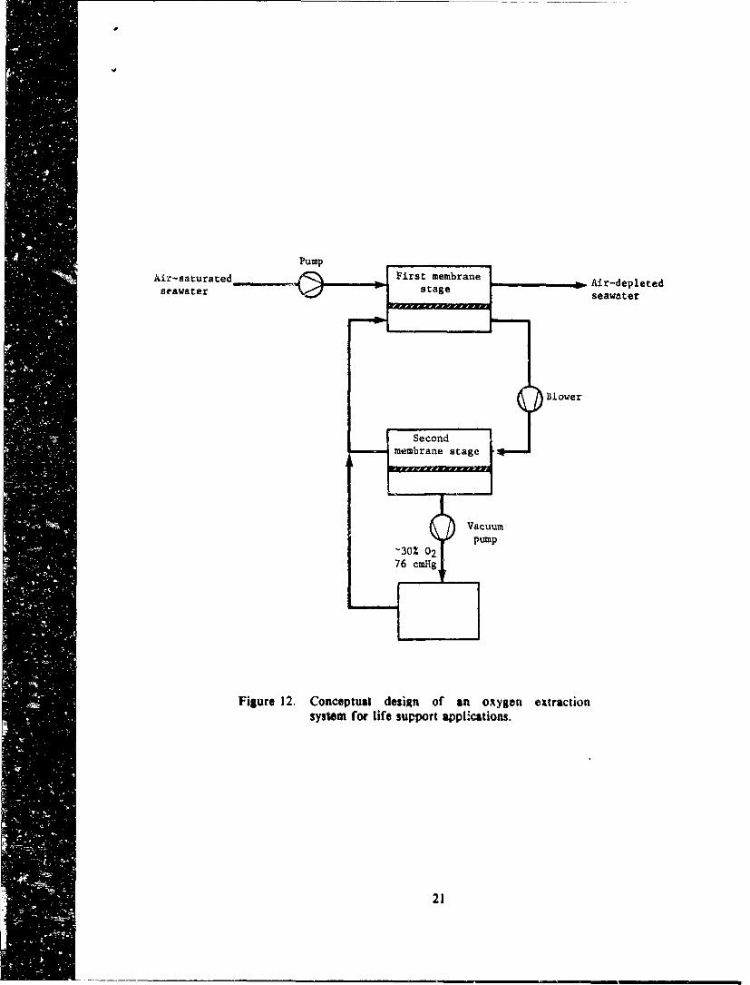
An oxygen extraction design similar to the one shown in Figure I 1(b) couldbe used to generate oxygen for life support. The system in Figure I i(b) producesa permeate gas stream at slightly less than atmospheric pressure, with an oxygencontent and partial pressure too low fo, direct use irt a life-support system. Forlife-support, oxygen would have to be generated at a partial pressure over0.21 atm sad consequently a second membrate stage would be necessary. Aconceptual design Is shown in Figure 12. This two-stage, sweep-mode systemcould produce approximately 30% oiygen at normal pressure. No nitrogen wouldbe extracted by virtue of the sweep mode. The sweep stream would also cause atleast part of the carbon dioxide produced by respiration to diffuse in the reversedirection into the seawater. The system required to produce oxygen forsubmarine life support would be larger and more complicated than systemsproducing oxygen for fuel cells. We estimate that the vacuum pump would needat least one hp per crew member and thit would raise concern about the noiselevel generated by the system.
20
Pum
Air-saturated First membrane .0Air-depletedseawater saeseawater
system fo mblif e supo t age~ato
21 uu

d
VIII. CONCLUSIONS
The experimental work performed has shown that a membrane system iscapable of extracting dissolved oxygen from seawater. The membrane transportsoxygen by simple diffusion and is capable of withstanding relatively large pressuredifferences. A preliminary system design analysis has shown that the system canbe operated such that an equilibrium is reached where oxygen, but no nitrogen orcarbon dioxide, is extracted from the seawater. This eliminates the need tocompress and vent these gases. Two applications were considered, (I) oxygen forsubmerged fuel cells, and (2) oxygen for life support aboard submarines. The fuelcell application is considered the more promising.
The objectives of an eventual Phase II program would be to construct andoperate a laboratory-scale oxygen extraction system operating in the sweep-mode.Oxygen would be continuously removed from the sweep stream, as is the case inthe fuel cell application. An important goal of the Phase II program would be todevelop membrane modules with a very low feed-to-residue pressure drop. Thiswould increase the energy efficiency of the oxygen extraction system, a crucialconcern in the fuel cell application.
REFERENOES
1. R.C. Binning, R.J. Lee, J.F. Jennings, E.C. Martin, "S,,paration of LiquidMixtures by Permeation,. Ind. & Eng. Chem. 53. 45 (1961).
2. D.R. Paul, O.M. Ebra-Lima, "Pressure-Induced Diffusion of Organic LiquidsThrough Highly Swollen Polymer Membranes,' J. Aoel. Polvm. &i. 14. 2201(1970).
3. F.W. Greenlaw, W.D. Prince, R.A. Shelden, E.V. Thompson, *Dependence ofDiffusive Permeation Rates on Upstream and Downstream Pressure," JL Memb.
• '&" 141 (1977).
4. Randbook of Batteries and Fuel Cells, D. Linden, Ed., page 42-1 to 42-11,McGraw-Hill, New York (1982).
22