sentry - dunham-bushdunham-bush.co.uk/brochures/door_curtains/db_sentry_door_curtain.… · 5...
TRANSCRIPT
1
Sentry
Door Curtain
• Energy efficient EC motors • Cased and concealed models • LPHW and electric heating • Comprehensive range of controls

2
CONTENTS PAGE
IDENTIFICATION Introduction 2Authority 2
DESCRIPTIONRange 2Features 3Typical installation 4Controls & Accessories 5
PERFORMANCE 7-8Correction factors 7Hydraulic resistance 8Electrical data 10Coil capacities & mass 10
APPLICATION 11General 11Selection 11Equations 12Example 12Dimensions 13-16
ENGINEERING SPECIFICATION General 17Basic unit 17Hot water coil 17Electric heating coil 17Fan motor platform 17Fan assemblies 17Motors 17Air filters 17Electrical connection box 17Packing 17Accessories 17Hanging brackets 18-20
CONSTRUCTIONHandling 21Storage 21Preparation 21Installation 21Pipework connections 21Electrical connections 21
PRICES & CONDITIONS OF SALE Prices 21Supply 21Availability 21Ordering 21Delivery 21
TECHNICAL SUPPORT SERVICESProduct support 21
ORDERING Product string 22Remote items 23
IntroductionThe Dunham–Bush Sentry door curtain is an ideal solution to limit the ingress of cold air during “open doorway trading” in retail premises or busy pedestrian traffic in commercial and public buildings.
The technology of door curtains is well proven. The vertical air stream across an open doorway provides a virtual barrier, which separates indoor and outdoor environments. This air barrier prevents ‘inversion’ arising from different air temperatures; thus reducing energy consumption, increasing internal comfort and usable floor area. The door curtain has no effect on pedestrian traffic flow.
Sentry door curtains are designed and manufactured to the high quality that is synonymous with Dunham–Bush products, complemented with a wide range of options to suit varied applications.
AuthorityIt is accepted practice at Dunham-Bush to maintain exceptional standards in engineering and quality. To this end, Dunham–Bush operates a quality system and is registered as a firm of assessed capability to BS EN ISO 9001: 2008.
RangeSentry door curtains are available in a range of models, covering horizontal or vertical orientation, each model with left or right handed coil connections and top or back pipe entry into the casing. Each model is available in three sizes; Figures 10, 15 and 20
Model DescriptionCH Cased horizontal unitCV Cased vertical unitBH Basic horizontal unitBV Basic vertical unit
Size DesignationOverall Length (mm)
Nominal Duty (kW)
Figure 10 1000 5Figure 15 1500 10Figure 20 2000 15
All Sentry door curtains comprise rotor motor fans, G2 filter, LPHW or electric heating coil and electrical connections box. Models CH and CV are coated in durable white polyester power, (RAL9010) with a satin finish with grilles coated in black polyester (BS 00 E53) matt finish. Any standard RAL or BS colour is available on request.
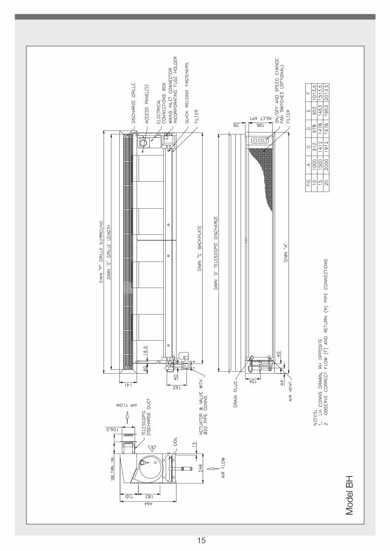
Models BH & BV have self finished galvanized steel casings for installation into a bulkhead. The supply air grille is fitted with an adjustable telescopic duct for flexibility.
IDENTIFICATION
DESCRIPTION
3
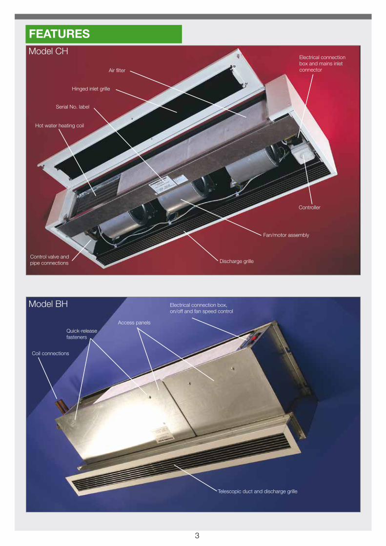
Model CH
Model BH
Hinged inlet grille
Hot water heating coil
Serial No. label
Control valve and pipe connections Discharge grille
Fan/motor assembly
Controller
Air filter
Electrical connection box and mains inlet connector
Access panels
Telescopic duct and discharge grille
Quick-release fasteners
Coil connections
Electrical connection box, on/off and fan speed control
FEATURES

4
= Access panels
Top entry pipework(only option on this model)
Top entry pipework(only option on this model)
Back entry pipework
Front entry pipework
Front entry pipework(only option on this model)
TYPICAL INSTALLATION

5
CONTROLS & ACCESSORIESSentry door curtains are available with two hot water coil options• WA6 for conventional LPHW, typically flow and return 80/70°C or 80/60°C• WA8 for low grade hot water, typically flow and return 55/35°CAll coils are available with automatic air vents optional fixed or adjustable LTC thermostats.
Alternatively, Sentry is available with electric heating elements;• E05 5 kW; Fig 10 size only• E08 7.5kW; Fig 10 and Fig 15 sizes• E09 9kW; Fig 20 size only• E12 12kW; Fig 15 and Fig 20 sizes• E15 15kW; Fig 20 size only
All electric elements required a 415V/3ph/50Hz supply and include a optional zero volt switching relay which provides heat output via a pulse width modulating signal (PWM) control. (PWM can be fitted or by external BMS signal).
Table 1: Thermal control and fan speed options can be selected from the table below. (refer to pages 22 & 23)
Heating medium Option 19 - Standard Thermal Packages Option 14 - Remote fan speed
LPHW
W1 - Fitted neon on/off switch, fitted fan speed potentiometer, fitted commissioning voltmeter, with no thermal control.
N - None 1 - On/off switch 2 - Speed potentiometer 3 - On/off switch & speed potentiometer
W2 - Fitted neon on/off switch, fitted fan speed potentiometer, fitted commissioning voltmeter, PI controller & discharge air sensor.
N - None 1 - On/off switch 2 - Speed potentiometer 3 - On/off switch & speed potentiometer
WQ - Special Q - Specify
Electric
E1 - Fitted neon on/off switch, fitted fan speed potentiometer, fitted commissioning voltmeter, with no thermal control,
N - None 1 - On/off switch
E2 - Fitted neon on/off switch, fitted fan speed potentiometer, fitted commissioning voltmeter, PI controller & discharge air sensor .
N - None 1 - On/off switch
EQ - Special Q - Specify
Common ControlsAll Sentry door curtains are supplied with a fitted on/off switch complete with a red indicator lamp; this is fitted behind the access door/inlet grille on cased units (Models CH and CV) or on the control box on concealed units (Models BH and BV)
EC motors can be controlled with an infinitely variable speed control by selecting a fitted fan speed potentiometer and commissioning voltmeter. Where the remote fan speed potentiometer option is selected the fitted voltmeter is excluded.Note; remote potentiometers are for LPHW applications only.
A 24V relay is offered in most applications, this can be used as an enable relay energised from a remote BMS source, or as part of the volt-free LSV on/off switch circuit.
6
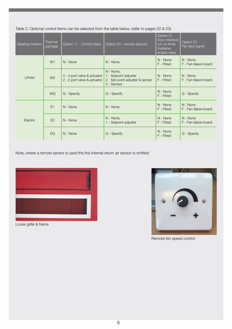
Table 2: Optional control items can be selected from the table below. (refer to pages 22 & 23)
Heating mediumThermal package
Option 17 - Control Valve Option 20 - remote sensors
Option 21 - Door interlock run on timer (replaces enable relay)
Option 22 - Fan fault signal
LPHW
W1 N - None N - NoneN - None F - Fitted
N - None F - Fan failure board
W24 - 4 port valve & actuator 2 - 2 port valve & actuator
N - None, 1 - Setpoint adjuster 2 - Set-point adjuster & sensor 3 - Semsor
N - None F - Fitted
N - None F - Fan failure board
WQ Q - Specify Q - SpecifyN - None F - Fitted
Q - Specify
Electric
E1 N - None N - NoneN - None F - Fitted
N - None F - Fan failure board
E2 N - NoneN - None, 1 - Setpoint adjuster
N - None F - Fitted
N - None F - Fan failure board
EQ N - None Q - SpecifyN - None F - Fitted
Q - Specify
Note; where a remote sensor is used the the internal return air sensor is omitted
Loose grille & frame
Remote fan speed control
7
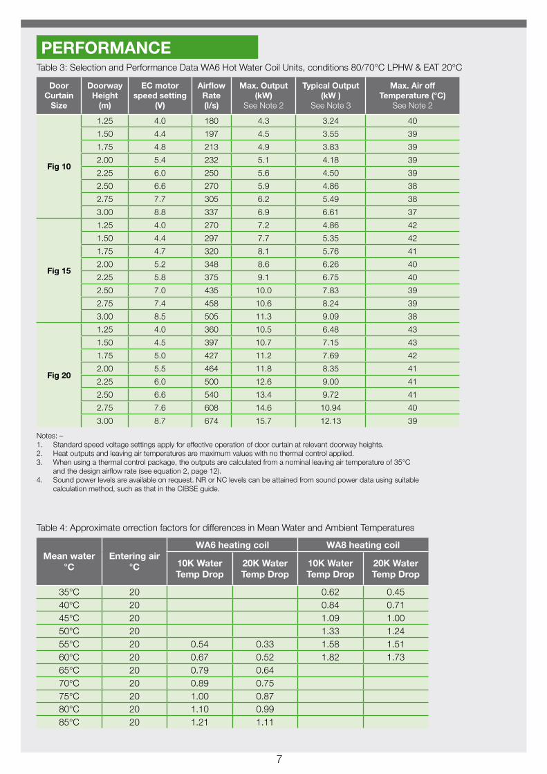
Table 3: Selection and Performance Data WA6 Hot Water Coil Units, conditions 80/70°C LPHW & EAT 20°C
Door Curtain
Size
Doorway Height
(m)
EC motor speed setting
(V)
Airflow Rate (l/s)
Max. Output (kW)
See Note 2
Typical Output (kW )
See Note 3
Max. Air off Temperature (°C)
See Note 2
Fig 10
1.25 4.0 180 4.3 3.24 40
1.50 4.4 197 4.5 3.55 39
1.75 4.8 213 4.9 3.83 39
2.00 5.4 232 5.1 4.18 39
2.25 6.0 250 5.6 4.50 39
2.50 6.6 270 5.9 4.86 38
2.75 7.7 305 6.2 5.49 38
3.00 8.8 337 6.9 6.61 37
Fig 15
1.25 4.0 270 7.2 4.86 42
1.50 4.4 297 7.7 5.35 42
1.75 4.7 320 8.1 5.76 41
2.00 5.2 348 8.6 6.26 40
2.25 5.8 375 9.1 6.75 40
2.50 7.0 435 10.0 7.83 39
2.75 7.4 458 10.6 8.24 39
3.00 8.5 505 11.3 9.09 38
Fig 20
1.25 4.0 360 10.5 6.48 43
1.50 4.5 397 10.7 7.15 43
1.75 5.0 427 11.2 7.69 42
2.00 5.5 464 11.8 8.35 41
2.25 6.0 500 12.6 9.00 41
2.50 6.6 540 13.4 9.72 41
2.75 7.6 608 14.6 10.94 40
3.00 8.7 674 15.7 12.13 39
PERFORMANCE
Notes: –1. Standard speed voltage settings apply for effective operation of door curtain at relevant doorway heights.2. Heat outputs and leaving air temperatures are maximum values with no thermal control applied.3. When using a thermal control package, the outputs are calculated from a nominal leaving air temperature of 35°C
and the design airflow rate (see equation 2, page 12).4. Sound power levels are available on request. NR or NC levels can be attained from sound power data using suitable
calculation method, such as that in the CIBSE guide.
Table 4: Approximate orrection factors for differences in Mean Water and Ambient Temperatures
Mean water °C
Entering air °C
WA6 heating coil WA8 heating coil
10K Water Temp Drop
20K Water Temp Drop
10K Water Temp Drop
20K Water Temp Drop
35°C 20 0.62 0.4540°C 20 0.84 0.7145°C 20 1.09 1.0050°C 20 1.33 1.2455°C 20 0.54 0.33 1.58 1.5160°C 20 0.67 0.52 1.82 1.7365°C 20 0.79 0.6470°C 20 0.89 0.7575°C 20 1.00 0.8780°C 20 1.10 0.9985°C 20 1.21 1.11
8
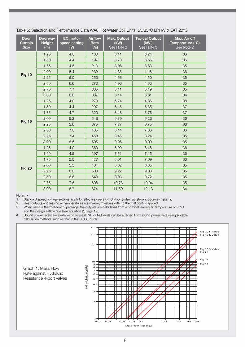
Table 5: Selection and Performance Data WA8 Hot Water Coil Units, 55/35°C LPHW & EAT 20°C
Door Curtain
Size
Doorway Height
(m)
EC motor speed setting
(V)
Airflow Rate (l/s)
Max. Output (kW)
See Note 2
Typical Output (kW )
See Note 3
Max. Air off Temperature (°C)
See Note 2
Fig 10
1.25 4.0 180 3.41 3.24 36
1.50 4.4 197 3.70 3.55 36
1.75 4.8 213 3.98 3.83 35
2.00 5.4 232 4.35 4.18 36
2.25 6.0 250 4.66 4.50 35
2.50 6.6 270 4.96 4.86 35
2.75 7.7 305 5.41 5.49 35
3.00 8.8 337 6.14 6.61 34
Fig 15
1.25 4.0 270 5.74 4.86 38
1.50 4.4 297 6.15 5.35 37
1.75 4.7 320 6.48 5.76 37
2.00 5.2 348 6.89 6.26 36
2.25 5.8 375 7.27 6.75 36
2.50 7.0 435 8.14 7.83 36
2.75 7.4 458 8.45 8.24 35
3.00 8.5 505 9.06 9.09 35
Fig 20
1.25 4.0 360 6.90 6.48 36
1.50 4.5 397 7.51 7.15 36
1.75 5.0 427 8.01 7.69 36
2.00 5.5 464 8.62 8.35 35
2.25 6.0 500 9.22 9.00 35
2.50 6.6 540 9.93 9.72 35
2.75 7.6 608 10.78 10.94 35
3.00 8.7 674 11.59 12.13 34
Notes: –1. Standard speed voltage settings apply for effective operation of door curtain at relevant doorway heights.2. Heat outputs and leaving air temperatures are maximum values with no thermal control applied.3. When using a thermal control package, the outputs are calculated from a nominal leaving air temperature of 35°C
and the design airflow rate (see equation 2, page 12).4. Sound power levels are available on request. NR or NC levels can be attained from sound power data using suitable
calculation method, such as that in the CIBSE guide.
Graph 1: Mass Flow Rate against Hydraulic Resistance 4-port valves
9
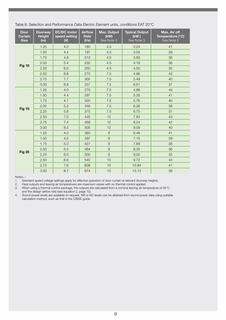
Door Curtain
Size
Doorway Height
(m)
EC/DC motor speed setting
(V)
Airflow Rate (l/s)
Max. Output (kW)
See Note 2
Typical Output (kW )
See Note 3
Max. Air off Temperature (°C)
See Note 2
Fig 10
1.25 4.0 180 4.5 3.24 41
1.50 4.4 197 4.5 3.55 39
1.75 4.8 213 4.5 3.83 38
2.00 5.4 232 4.5 4.18 36
2.25 6.0 250 4.5 4.50 35
2.50 6.6 270 7.5 4.86 43
2.75 7.7 305 7.5 5.49 40
3.00 8.8 337 7.5 6.61 37
Fig 15
1.25 4.0 270 7.5 4.86 43
1.50 4.4 297 7.5 5.35 41
1.75 4.7 320 7.5 5.76 40
2.00 5.2 348 7.5 6.26 38
2.25 5.8 375 7.5 6.75 37
2.50 7.0 435 12 7.83 43
2.75 7.4 458 12 8.24 42
3.00 8.5 505 12 9.09 40
Fig 20
1.25 4.0 360 9 6.48 41
1.50 4.5 397 9 7.15 39
1.75 5.0 427 9 7.69 38
2.00 5.5 464 9 8.35 36
2.25 6.0 500 9 9.00 35
2.50 6.6 540 15 9.72 43
2.75 7.6 608 15 10.94 41
3.00 8.7 674 15 12.13 39
Table 6: Selection and Performance Data Electric Element units, conditions EAT 20°C
Notes: –1. Standard speed voltage settings apply for effective operation of door curtain at relevant doorway heights.2. Heat outputs and leaving air temperatures are maximum values with no thermal control applied.3. When using a thermal control package, the outputs are calculated from a nominal leaving air temperature of 35°C
and the design airflow rate (see equation 2, page 12).4. Sound power levels are available on request. NR or NC levels can be attained from sound power data using suitable
calculation method, such as that in the CIBSE guide.

10
Door Curtain
Size
Doorway Height (m)
EC motor speed
setting (V)
Electrical data EC motors
Full load current (A)
Power (W)
Fig 10
1.25 4.0 0.46 571.50 4.4 0.56 711.75 4.8 0.66 842.00 5.4 0.80 1042.25 6.0 0.95 1252.50 6.6 1.15 15632.75 7.7 1.58 2113.00 8.8 2.05 278
Fig 15
1.25 4.0 0.70 861.50 4.4 0.84 1051.75 4.7 0.96 1212.00 5.2 1.12 1442.25 5.8 1.32 1722.50 7.0 1.91 2492.75 7.4 2.17 2903.00 8.5 2.76 380
Fig 20
1.25 4.0 0.87 1051.50 4.5 1.07 1341.75 5.0 1.23 1572.00 5.5 1.52 1942.25 6.0 1.80 2312.50 6.6 2.11 2832.75 7.6 2.80 3843.00 8.7 3.63 505
Door Curtain
Size
WA6 Coil capacity (litres)
WA8 Coil capacity (litres)
Unit mass Cased
(kg)
Unit mass Basic (kg)
Fig 10 1.0 1.1 45 40Fig 15 1.55 1.7 60 55Fig 20 2.1 2.2 80 75
Table 7 Electrical Data
Table 8: Selection and Performance Mass & Coil Capacities

11
APPLICATIONSelectionA door curtain is in effect a barrier against natural airstreams entering a doorway. Elevated pressure differences between inside and outside and high leakage rates will result in a high degree of infiltration and heat flux across the doorway. These pressure differences are likely to occur with: –
• Higher wind speeds into the door from outside• If the building is relatively leaky
Door curtains are best applied to well sealed spaces, where the building leakage should typically be less than 5m³/hr/m² of building envelope @ 25Pa.
The following guidelines can be used to assist the designer in selecting an air curtain: -
• Ensure that the building is sealed to minimise air leakage.
• Determine the overall width and height of the doorway opening.
• For the given doorway width, the door curtain(s) should be approximately 150mm wider at each end.
• For the given doorway height, select the appropriate supply air speed voltage (see tables on pages 7, 8 & 9).
(Note: supply air speed will be factory set to provide a continuous air velocity of 0.3m/s at 150mm above floor level. In most applications, air velocity at the discharge grille will be between 4m/s and 6m/s)
• Supply air temperature should be kept as low as possible to save energy but within acceptable limits to ensure comfort conditions (typically 30-35°C).
GeneralDoor curtain technology is well proven as a means to inhibit heat loss, or gain, through doorways in retail and commercial premises. Doorways with heavy pedestrian traffic flow rates or “open door trading” shops are especially suitable applications. Door curtains operate by providing a continuous stream of conditioned air across the face of a doorway. In winter, the curtain prevents the warm air passing out of the top of the door and the cold air entering beneath it, this prevents ‘inversion’ which forces the warm air out, wasting energy. In summer, with the fans running and the heat switched off, the same theory applies and prevents conditioned air escaping.
When operating in the right conditions, a door curtain forms a virtual barrier between the outside and inside environments. It is essential to note that door curtains are not intended to provide warm air heating for the building space; this should be provided by other heating devices. When specified the temperature sensor can be mounted in the return air path to assist with heating the space, but this is energy inefficient. Elevated leaving air temperatures will adversely affect the door curtains downward air throw, (due to its inherent buoyancy), and increase the heat lost on the outside face of the air stream.
Typical application of air curtain over doorway entrance. (Reproduced by permission from BSRIA)
12
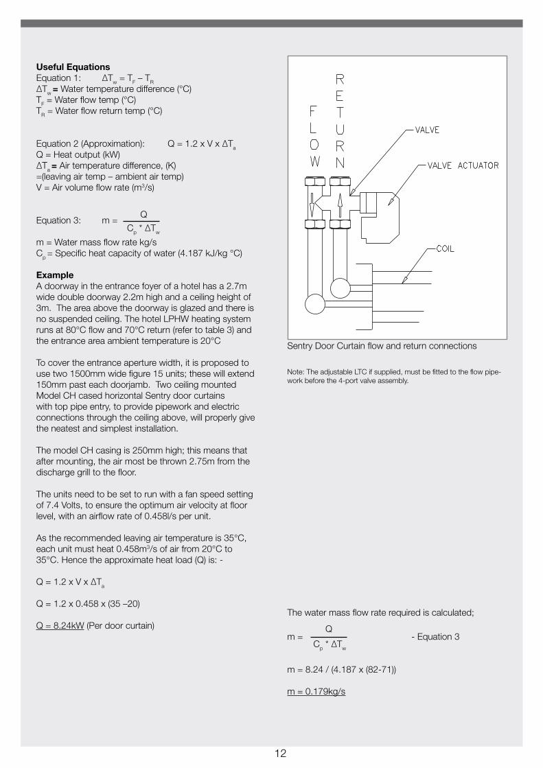
Useful EquationsEquation 1: ∆Tw = TF – TR
∆Tw = Water temperature difference (°C)TF = Water flow temp (°C)TR = Water flow return temp (°C)
Equation 2 (Approximation): Q = 1.2 x V x ∆Ta
Q = Heat output (kW)∆Ta = Air temperature difference, (K) =(leaving air temp – ambient air temp)V = Air volume flow rate (m3/s)
Equation 3: m =
m = Water mass flow rate kg/sCp = Specific heat capacity of water (4.187 kJ/kg °C)
ExampleA doorway in the entrance foyer of a hotel has a 2.7m wide double doorway 2.2m high and a ceiling height of 3m. The area above the doorway is glazed and there is no suspended ceiling. The hotel LPHW heating system runs at 80°C flow and 70°C return (refer to table 3) and the entrance area ambient temperature is 20°C
To cover the entrance aperture width, it is proposed to use two 1500mm wide figure 15 units; these will extend 150mm past each doorjamb. Two ceiling mounted Model CH cased horizontal Sentry door curtains with top pipe entry, to provide pipework and electric connections through the ceiling above, will properly give the neatest and simplest installation.
The model CH casing is 250mm high; this means that after mounting, the air most be thrown 2.75m from the discharge grill to the floor.
The units need to be set to run with a fan speed setting of 7.4 Volts, to ensure the optimum air velocity at floor level, with an airflow rate of 0.458l/s per unit.
As the recommended leaving air temperature is 35°C, each unit must heat 0.458m3/s of air from 20°C to 35°C. Hence the approximate heat load (Q) is: -
Q = 1.2 x V x ∆Ta
Q = 1.2 x 0.458 x (35 –20)
Q = 8.24kW (Per door curtain)The water mass flow rate required is calculated;
m = - Equation 3
m = 8.24 / (4.187 x (82-71))
m = 0.179kg/s
Q
Cp * ∆Tw
Q
Cp * ∆Tw
Note: The adjustable LTC if supplied, must be fitted to the flow pipe-work before the 4-port valve assembly.
Sentry Door Curtain flow and return connections
13
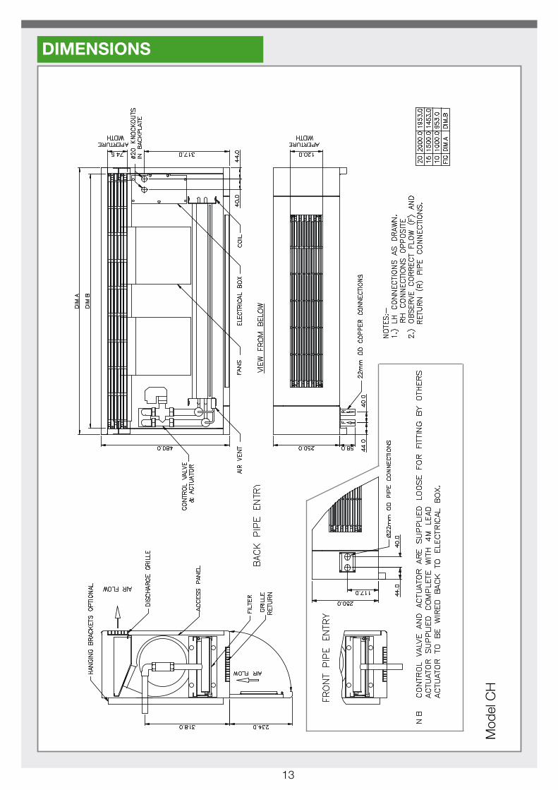
DIMENSIONS
Mod
el C
H

14
Mod
el C
V
15
Mod
el B
H

16
Mod
el B
V
17
ENGINEERING SPECIFICATIONGeneralThe Sentry door curtain shall be manufactured by Dunham–Bush Ltd, Downley Road, Havant, Hampshire, PO2 9JD. The models, figure numbers and quantities shall be as indicated in the schedule and /or on the drawings. The construction of all heaters shall comply with the following specification.
Basic unitEach Sentry door curtain shall comprise of a sheet steel casing with access panel, heating coil/element, motor/fan platform and air filter. Where appropriate to the model, grilles shall be fitted to the casing.
Hot water coilWhen specified, hot water heating coils shall be provided. Coils shall be constructed from 9.35mm O.D. drawn copper tubes, expanded into single plate corrugated aluminium fins and brazed to copper headers. Flow and return connection shall be 22mm O.D. copper tube tails or DN20 female compression fittings as appropriate. Coils shall be tested to a minimum pressure of 24bar gauge. Coils shall be fitted with automatic ‘Taco’ type air vents. Coils shall be suitable for maximum cold test pressure 9.0bar gauge and maximum working pressure 7.0bar gauge.
Electric heating elementsWhen specified, electric heating elements shall be provided. Elements shall be rated at 415V 3 phase and shall be arranged to give the design output specified. The output of the element shall be controlled by a zero voltage thyristor controller.
A self-resetting high limit thermostat, set to operate at 75°C, shall protect each element circuit and a manual reset thermostat set to operate at 95°C, for additional safety.
Fan/motor platformFan/motor platforms shall be manufactured from 1.6mm galvanised steel and shall be fitted with the centrifugal fan/motor assemblies.
Fan assembliesFans shall be double inlet, double width, direct drive, centrifugal type with low noise, forward curved, multi–blade ‘tab lock’ galvanised steel impellors housed in galvanised steel scrolls. Fans shall be statically and dynamically balanced.
Air filterAir Filters shall be washable, composed of thermally bonded polyester fibres. Filters shall be BS EN 779, class G2 (EU2).
EC MotorsEC Fan Motors - Fan motors shall be high efficiency, low noise, electronically communtated ‘3-core dc’, external rotor type with resilient mounts to minimise noise and vibration. Winding insulation shall be rated to Class ‘B’ and bearing shall be ‘sealed for life’. Units require a 200/277V 50 or 60Hz single phase power supply.
Electrical connections boxEach unit shall be provided with a well-ventilated electrical box. The box shall contain a terminal block, autotransformer, transformer fuse and space for relays etc, when specified. Note, electric element units to be fused externally by others.
EC Fan motor speed controlVariable speed control shall be affected by a fitted or remote speed potentiometer or a 0-10V DC input signal from a propitiatory BMS controller.
PackagingEach Sentry door curtain shall be individually packed in, protective shrink–wrapping and palletised. The Sentry Door Curtain shall be marked with the Model, Figure Number, Serial Number and any other reference specified on the order. AccessoriesIf specified, accessories listed in the manufacturer’s Product Catalogue shall be provided.
18
(Not
sup
plie
d by
Dun
ham
-Bus
h)
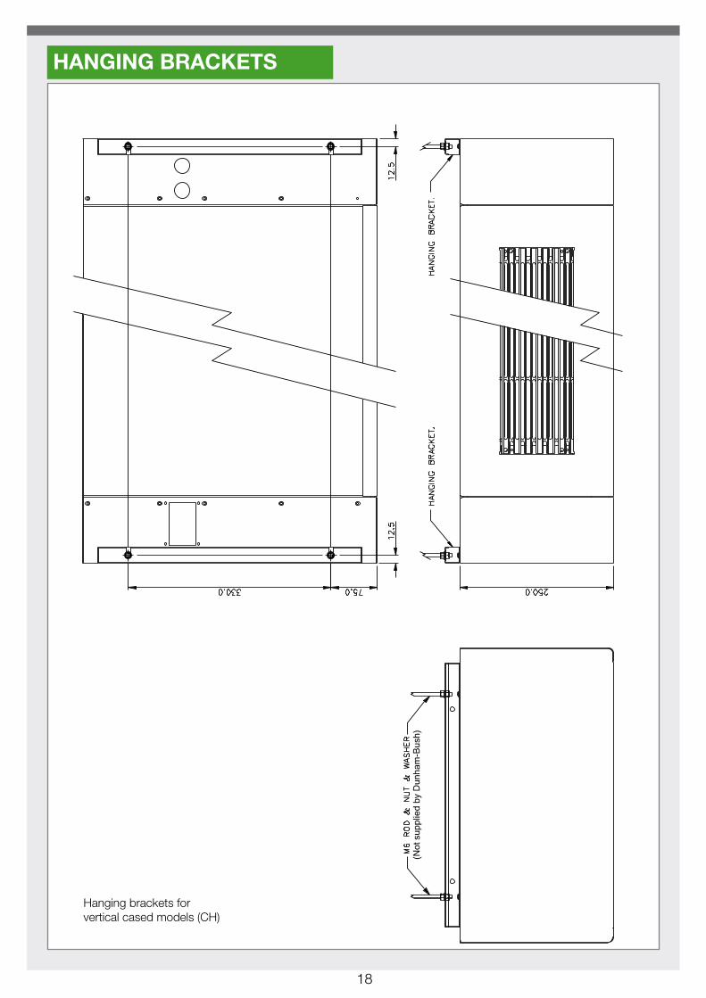
Hanging brackets for vertical cased models (CH)
HANGING BRACKETS

19
(Not
sup
plie
d by
Dun
ham
-Bus
h)(M
6 sc
rew
s su
pplie
d by
Dun
ham
-Bus
h)
Vertical hanging plate for vertical cased model (CV)
20
(Not
sup
plie
d by
Dun
ham
-Bus
h)
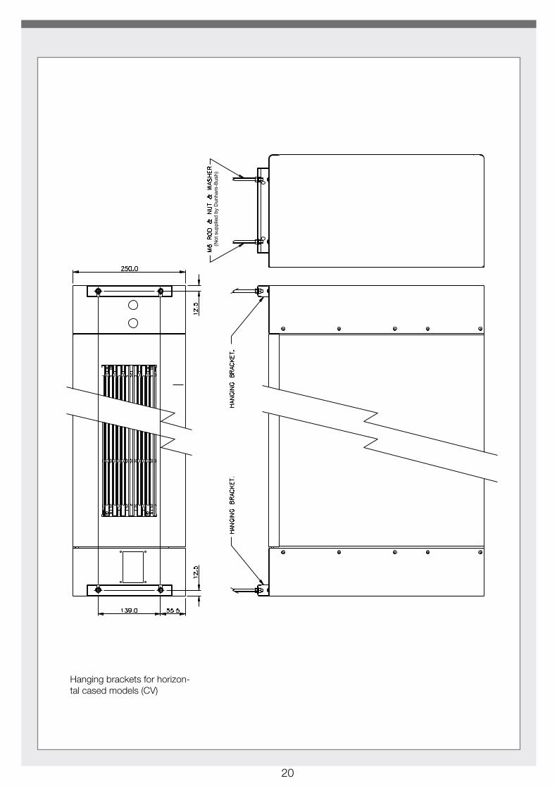
Hanging brackets for horizon-tal cased models (CV)
21
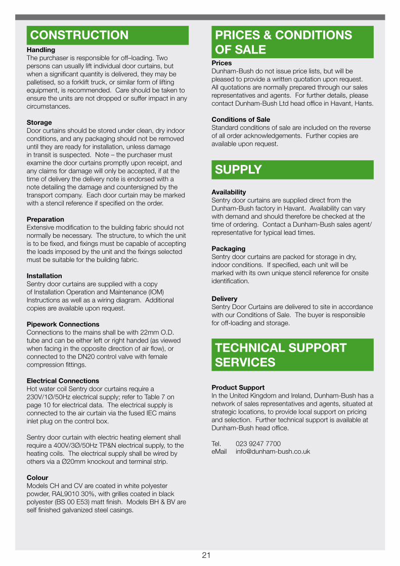
HandlingThe purchaser is responsible for off–loading. Two persons can usually lift individual door curtains, but when a significant quantity is delivered, they may be palletised, so a forklift truck, or similar form of lifting equipment, is recommended. Care should be taken to ensure the units are not dropped or suffer impact in any circumstances.
StorageDoor curtains should be stored under clean, dry indoor conditions, and any packaging should not be removed until they are ready for installation, unless damage in transit is suspected. Note – the purchaser must examine the door curtains promptly upon receipt, and any claims for damage will only be accepted, if at the time of delivery the delivery note is endorsed with a note detailing the damage and countersigned by the transport company. Each door curtain may be marked with a stencil reference if specified on the order.
PreparationExtensive modification to the building fabric should not normally be necessary. The structure, to which the unit is to be fixed, and fixings must be capable of accepting the loads imposed by the unit and the fixings selected must be suitable for the building fabric.
InstallationSentry door curtains are supplied with a copy of Installation Operation and Maintenance (IOM) Instructions as well as a wiring diagram. Additional copies are available upon request.
Pipework ConnectionsConnections to the mains shall be with 22mm O.D. tube and can be either left or right handed (as viewed when facing in the opposite direction of air flow), or connected to the DN20 control valve with female compression fittings.
Electrical ConnectionsHot water coil Sentry door curtains require a 230V/1Ø/50Hz electrical supply; refer to Table 7 on page 10 for electrical data. The electrical supply is connected to the air curtain via the fused IEC mains inlet plug on the control box.
Sentry door curtain with electric heating element shall require a 400V/3Ø/50Hz TP&N electrical supply, to the heating coils. The electrical supply shall be wired by others via a Ø20mm knockout and terminal strip.
ColourModels CH and CV are coated in white polyester powder, RAL9010 30%, with grilles coated in black polyester (BS 00 E53) matt finish. Models BH & BV are self finished galvanized steel casings.
PricesDunham-Bush do not issue price lists, but will be pleased to provide a written quotation upon request. All quotations are normally prepared through our sales representatives and agents. For further details, please contact Dunham-Bush Ltd head office in Havant, Hants.
Conditions of SaleStandard conditions of sale are included on the reverse of all order acknowledgements. Further copies are available upon request.
AvailabilitySentry door curtains are supplied direct from the Dunham-Bush factory in Havant. Availability can vary with demand and should therefore be checked at the time of ordering. Contact a Dunham-Bush sales agent/representative for typical lead times.
PackagingSentry door curtains are packed for storage in dry, indoor conditions. If specified, each unit will be marked with its own unique stencil reference for onsite identification.
DeliverySentry Door Curtains are delivered to site in accordance with our Conditions of Sale. The buyer is responsible for off-loading and storage.
Product SupportIn the United Kingdom and Ireland, Dunham-Bush has a network of sales representatives and agents, situated at strategic locations, to provide local support on pricing and selection. Further technical support is available at Dunham-Bush head office.
Tel. 023 9247 7700 eMail [email protected]
CONSTRUCTION PRICES & CONDITIONS OF SALE
SUPPLY
TECHNICAL SUPPORT SERVICES
22
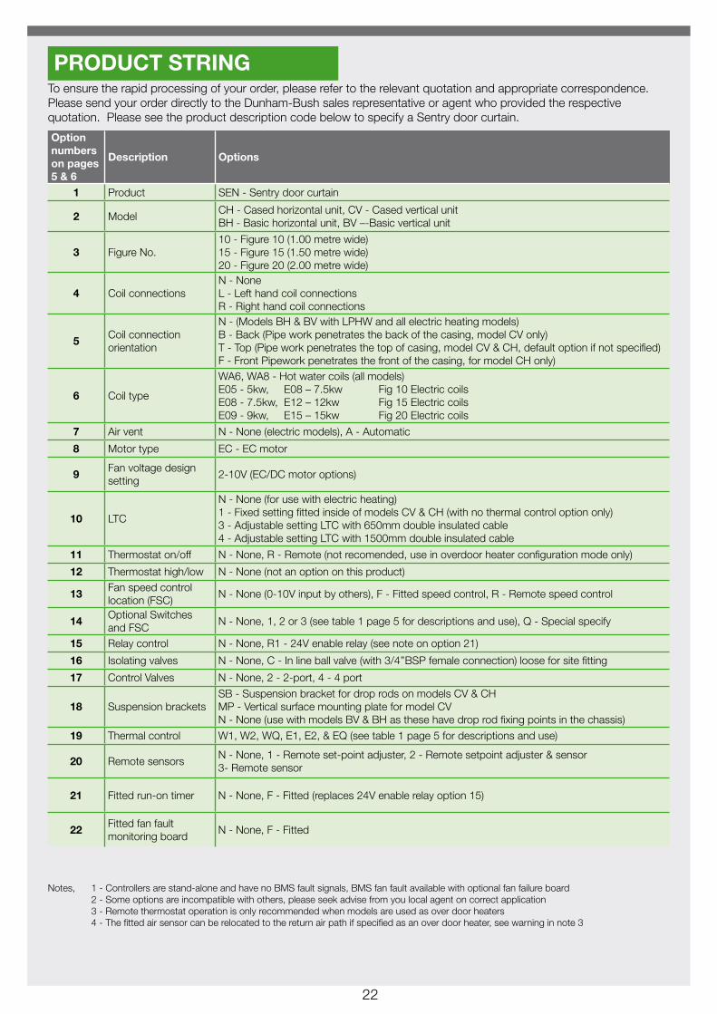
To ensure the rapid processing of your order, please refer to the relevant quotation and appropriate correspondence. Please send your order directly to the Dunham-Bush sales representative or agent who provided the respective quotation. Please see the product description code below to specify a Sentry door curtain.
Option numbers on pages 5 & 6
Description Options
1 Product SEN - Sentry door curtain
2 ModelCH - Cased horizontal unit, CV - Cased vertical unitBH - Basic horizontal unit, BV –-Basic vertical unit
3 Figure No.10 - Figure 10 (1.00 metre wide)15 - Figure 15 (1.50 metre wide)20 - Figure 20 (2.00 metre wide)
4 Coil connectionsN - NoneL - Left hand coil connectionsR - Right hand coil connections
5Coil connection orientation
N - (Models BH & BV with LPHW and all electric heating models)B - Back (Pipe work penetrates the back of the casing, model CV only)T - Top (Pipe work penetrates the top of casing, model CV & CH, default option if not specified)F - Front Pipework penetrates the front of the casing, for model CH only)
6 Coil type
WA6, WA8 - Hot water coils (all models) E05 - 5kw, E08 – 7.5kw Fig 10 Electric coilsE08 - 7.5kw, E12 – 12kw Fig 15 Electric coils E09 - 9kw, E15 – 15kw Fig 20 Electric coils
7 Air vent N - None (electric models), A - Automatic
8 Motor type EC - EC motor
9Fan voltage design setting
2-10V (EC/DC motor options)
10 LTC
N - None (for use with electric heating)1 - Fixed setting fitted inside of models CV & CH (with no thermal control option only)3 - Adjustable setting LTC with 650mm double insulated cable4 - Adjustable setting LTC with 1500mm double insulated cable
11 Thermostat on/off N - None, R - Remote (not recomended, use in overdoor heater configuration mode only)
12 Thermostat high/low N - None (not an option on this product)
13Fan speed control location (FSC)
N - None (0-10V input by others), F - Fitted speed control, R - Remote speed control
14Optional Switches and FSC
N - None, 1, 2 or 3 (see table 1 page 5 for descriptions and use), Q - Special specify
15 Relay control N - None, R1 - 24V enable relay (see note on option 21)
16 Isolating valves N - None, C - In line ball valve (with 3/4’’BSP female connection) loose for site fitting
17 Control Valves N - None, 2 - 2-port, 4 - 4 port
18 Suspension bracketsSB - Suspension bracket for drop rods on models CV & CHMP - Vertical surface mounting plate for model CVN - None (use with models BV & BH as these have drop rod fixing points in the chassis)
19 Thermal control W1, W2, WQ, E1, E2, & EQ (see table 1 page 5 for descriptions and use)
20 Remote sensorsN - None, 1 - Remote set-point adjuster, 2 - Remote setpoint adjuster & sensor 3- Remote sensor
21 Fitted run-on timer N - None, F - Fitted (replaces 24V enable relay option 15)
22Fitted fan fault monitoring board
N - None, F - Fitted
Notes, 1 - Controllers are stand-alone and have no BMS fault signals, BMS fan fault available with optional fan failure board 2 - Some options are incompatible with others, please seek advise from you local agent on correct application 3 - Remote thermostat operation is only recommended when models are used as over door heaters 4 - The fitted air sensor can be relocated to the return air path if specified as an over door heater, see warning in note 3
PRODUCT STRING
23
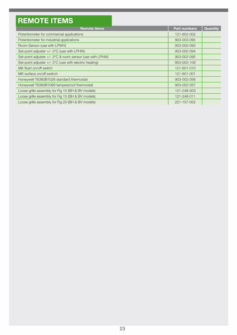
Remote items Part numbers Quantity
Potentiometer for commercial applications 121-602-002
Potentiometer for industrial applications 903-003-095
Room Sensor (use with LPWH) 953-002-093
Set-point adjuster +/- 3°C (use with LPHW) 953-002-094
Set-point adjuster +/- 3°C & room sensor (use with LPHW) 953-002-095
Set-point adjuster +/- 3°C (use with electric heating) 953-002-109
MK flush on/off switch 121-601-010
MK surface on/off switrch 121-601-001
Honeywell T6360B1028 standard thermostat 903-002-056
Honeywell T6360B1069 tamperproof thermostat 903-002-057
Loose grille assembly for Fig 10 (BH & BV models) 121-248-003
Loose grille assembly for Fig 15 (BH & BV models) 121-248-011
Loose grille assembly for Fig 20 (BH & BV models) 221-157-002
REMOTE ITEMS

24
Manufacturer reserves the right to change any product specification without notice
128-000-000-B
October 2015
Dunham-Bush Ltd Downley Road
Havant Hampshire PO9 2JD
Tel. 023 9247 7700 Fax. 023 9245 3601
Email: [email protected] www.dunham-bush.co.uk