sensors polyurethane composite fibers for ultrasensitive, … · 2019-03-11 · using a sewing...
TRANSCRIPT

1
Highly Stretchable Multi-Walled Carbon Nanotube/Thermoplastic
Polyurethane Composite Fibers for Ultrasensitive, Wearable Strain
Sensors
Zuoli He,a Gengheng Zhou, a, b, * Joon-Hyung Byun,a, * Sang-Kwan Lee,a, * Moon-Kwang Um,a
Byeongjin Park,a Taehoon Kim,a Sang Bok Lee,a Tsu-Wei Chou c
a Composites Research Division, Korea Institute of Materials Science, 797 Changwon-daero,
Changwon, Gyeongnam 51508, South Korea
b Division of Advanced Nanomaterials, Suzhou Institute of Nano-Tech and Nano-Bionics, Chinese
Academy of Sciences, Suzhou, 215123, PR China
c Department of Mechanical Engineering, University of Delaware, Newark, Delaware 19716,
United States
Electronic Supplementary Material (ESI) for Nanoscale.This journal is © The Royal Society of Chemistry 2019

2
Contents
EXPERIMENTAL SECTION ..............................................................................................................................3
Figure S1 Photograph of the experimental setup for wet spinning. ............................................................5
Figure S2 Tensile strength plots(a) and maximum failure strain plots(b) of the MWCNT/TPU fibers with
different weight ratios of MWCNTs and TPU. ..............................................................................................6
Figure S3 Structure changes in the porous composite fibers during a stretch/ release circle: a, schematic
illustration of the porous structural changes; b-c, SEM images of structure changes in high magnification
of MWCNT/TPU fiber and neat TPU fiber.....................................................................................................7
Figure S4 (a) Electrical conductivity of the MWCNT/TPU fibers versus filler concentration and (b) the
fitting of experimental data using the classical percolation theory. ............................................................8
Figure S5 (a)The tightly knotted MWCNT/TPU fiber; (b-m) Sewing images of MWCNT/TPU Fibers with
MWCNT-to-TPU weight ratio of 1:8. ............................................................................................................9
Figure S6 SEM images of MWCNT/TPU fibers with the weight ratio of 1:8 under different stretch ratios.
....................................................................................................................................................................10
Figure S7 (a) Photograph of weight-to-strain sensor based on the cloth woven by MWCNT/TPU fibers,
(b-c) the resistance responses of the sensor without anything on the cloth. ............................................11
Figure S8 Weight of the small objects being measured in our experiments: a, cloth button; b, button cell;
c, screw; d, 10 cent Korean coin; e, 50 cent Korean coin; f, 2cm magnetic bar. ........................................12
Figure S9 Fabrication of the wearable strain sensor. .................................................................................13
Figure S10 Relative change in resistance of MWCNT/TPU fiber based strain sensor in water and different
artificial sweats...........................................................................................................................................14

3
EXPERIMENTAL SECTION
Materials
Multi-walled carbon nanotubes (MWCNTs, TMC 220-10, Diameter: 8~15 nm, Length: 5~20 µm,
purity: ∼95% wt.%) were purchased from Nano Solution, Korea. Thermoplastic polyurethanes
(TPU) (80A) was obtained from Bayer Company (Germany). Polyester-based TPU (code Elastollan
1185A) was provided by BASF Co. Ltd. N,N-Dimethylformamide(DMF, 99.8 %), dicyclohexyl
carbodiimide (DCC, 99 %) and sodium dodecyl sulfate (SDS, 99%) were purchased from Sigma-
Aldrich. Acetone (99.5%) was purchased from Samchun Pure Chemical Company.
Synthesis of Highly Stretchable CNTs reinforced TPU fibers
3 g MWCNTs were dispersed into 97 g DMF solution (contains of DCC and SDS) to form uniformly
3 wt % MWCNTs DMF suspension under sonication for 2 h. To obtain different MWCNT-to-TPU
weight ratios, TPU particles with the desired weight were added into suspensions and DMF was
added to keep TPU about 8 wt % in the solution. Then the solution was kept at 95 °C overnight,
the MWCNT/TPU suspension could be used for the wet spinning process after cooling to room
temperature. In this research, the MWCNT-to-TPU weight ratios of the prepared suspensions
were 1:1, 1:3, 1:4, 1:5, 1:6, 1:8, 1:12 and 1:20, respectively. Such prepared suspension was
extruded into an acetone based (5 vol % DMF in acetone) coagulation solution by a syringe
through a spinneret with an inner diameter of 340 μm and the continuous fiber was collected on
an aluminum foil drum (movie S1). The obtained fibers were immersed into water at 80 oC for
about 2h to remove the residual solvents existing in the composite fibers. Finally, the fibers were
collected on thread spools as shown in Figure 1a.
Characterization
Optical and SEM images were taken by the optical microscopy (Nikon Eclipse Lv150N), scanning
electron microscope (SEM, SNE 4500M, SEC, Korea) and Field emission scanning electron
microscopy (FESEM, JSM-6700F, JEOL, Japan), respectively. Stress-strain curves of the composite
filament were obtained using a TA Instruments Q800 Dynamic Mechanical Analyzer (DMA).
Detailed information can be found in our recent work.
Electromechanical Response Measurement of the Fiber

4
To test the strain-sensing characteristics, a single fiber was attached on the motorized moving
stages (Ecopia, Step Motor Controller, FS100801A1P1) by copper scotch, and then uniform
stretch/release cycles were applied to the samples while the electrical response of the sensor
was recorded by a digital Source Meter (Keithley 2100) or a potentiostat (VSP-300 - Bio-Logic).
Weight-to-strain Sensors
A weight-to-strain cloth sensor was assembled by weaving the MWCNT/TPU fibers. A 11× 11
matrix was woven by MWCNT/TPU fibers with the distance of 5 mm to measure 2D resistances
change in this experiment. When the objects are positioned on the cloth sensor, the strain change
resulting from the weight could be monitored the object’s shape by measuring the resistance
change. Moreover, our weight-to-strain cloth sensor could detect the shape of the objects
individually and precisely. The resistance changes of the fiber crosses were also recorded by a
digital Source Meter.
3 Lines Wire-type Strain Sensors for Human Activities Monitor
The MWCNTs reinforced composite fiber was stitched on the elastic bandage with a cotton yarn
using a sewing machine(Fig. S10). Specifically, the fibers were connected with conductive wires
using silver paste and fixed by conductive tape and medical tape. For the monitoring of human
activity, the resistance changes of wire-type strain sensor-based electronic skin were recorded
by a digital Source Meter (Keithley 2100) every 100 ms.
Smart Glove
A smart glove was assembled with ten individual fiber-type strain sensors, with two sensors on
each finger (I on Bouchard's nodes, II on Metacarpophalangeal joints), which could monitor real-
time motions of fingers. The smart glove is integrated with a custom-made data acquisition
system with wire communication modules. Moreover, our smart glove could detect the motion
of each finger individually and precisely. The resistance-changed curve of our integrated smart
glove device was recorded by a digital Source Meter (Keithley 2100) to detect gestures.
5
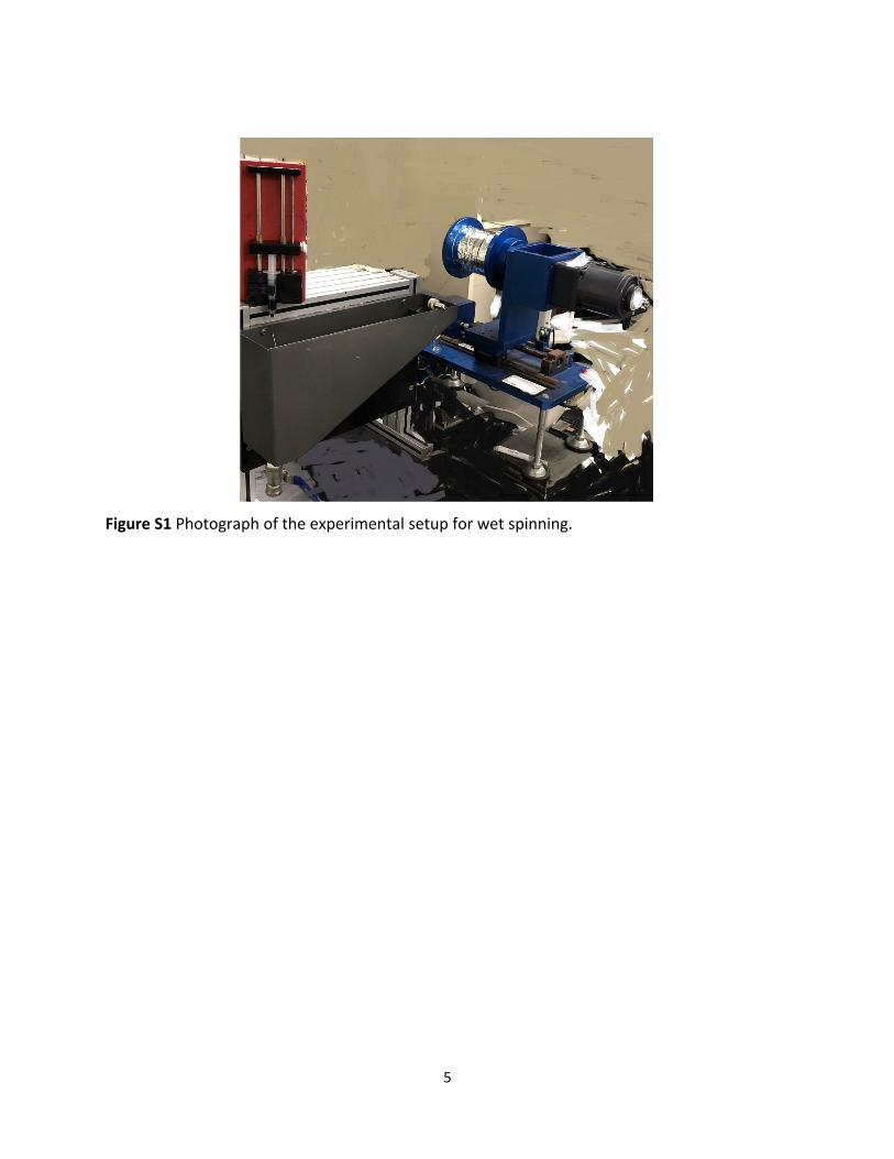
Figure S1 Photograph of the experimental setup for wet spinning.

6
Figure S2 Tensile strength plots(a) and maximum failure strain plots(b) of the MWCNT/TPU fibers
with different weight ratios of MWCNTs and TPU.
7
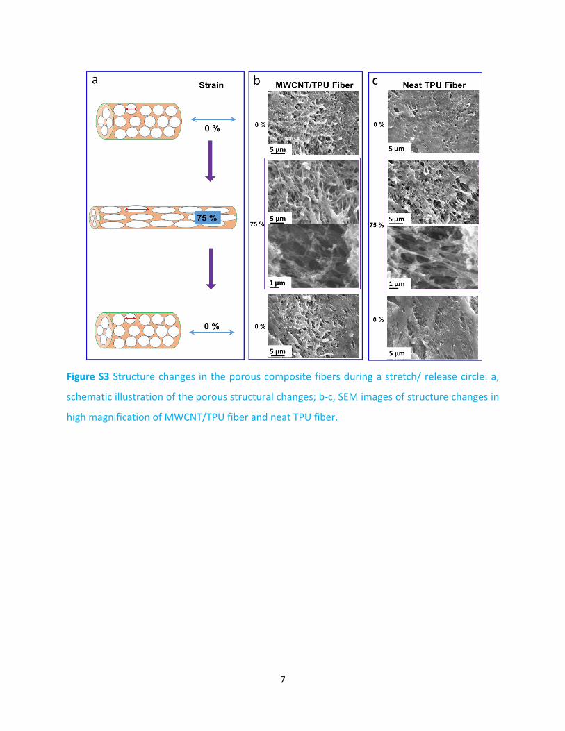
Figure S3 Structure changes in the porous composite fibers during a stretch/ release circle: a,
schematic illustration of the porous structural changes; b-c, SEM images of structure changes in
high magnification of MWCNT/TPU fiber and neat TPU fiber.

8
Figure S4 (a) Electrical conductivity of the MWCNT/TPU fibers versus filler concentration and (b)
the fitting of experimental data using the classical percolation theory.

9
Figure S5 (a)The tightly knotted MWCNT/TPU fiber; (b-m) Sewing images of MWCNT/TPU Fibers
with MWCNT-to-TPU weight ratio of 1:8.

10
Figure S6 SEM images of MWCNT/TPU fibers with the weight ratio of 1:8 under different stretch
ratios.

11
Figure S7 (a) Photograph of weight-to-strain sensor based on the cloth woven by MWCNT/TPU
fibers, (b-c) the resistance responses of the sensor without anything on the cloth.

12
Figure S8 Weight of the small objects being measured in our experiments: a, cloth button; b,
button cell; c, screw; d, 10 cent Korean coin; e, 50 cent Korean coin; f, 2cm magnetic bar.
Details of the objects:
a, Cloth Button: diameter: 11.196 mm; thickness: 1.791 mm; weight: 0.1741 g
b, Button Cell: diameter: 7.903 mm; thickness: 3.596 mm; weight: 0.5772 g
c, Screw: diameter: 7.824 mm; thickness: 3.833 mm; weight: 1.0601 g
d, 10 cent Korean Coin: diameter: 17.998 mm; thickness: 1.282 mm; weight: 1.2227 g
e, 50 cent Korean Coin: diameter: 21.608 mm; thickness: 1.424 mm; weight: 4.1698 g
f, 2cm Magnetic Bar: diameter: 7.118 mm; length: 1.996 mm; weight: 2.2836 g

13
Figure S9 Fabrication of the wearable strain sensor.

14
Figure S10 Relative change in resistance of MWCNT/TPU fiber based strain sensor in water and
different artificial sweats.