sensorless pmsm field-oriented control on kinetis · pdf filehardware requirements sensorless...
TRANSCRIPT

© 2016 NXP B.V.
Sensorless PMSM Field-Oriented Control
on Kinetis KV31 with FreeRTOS & eGUI By: Marek Zeman
1. Introduction
This application note describes the implementation of
the sensorless Motor Control Reference Solution
Package (MCRSP) software for a 3-phase Permanent
Magnet Synchronous Motor (PMSM) with the
FreeRTOS OS (including the motor-parameters
identification algorithm) on 32-bit Kinetis V series
MCUs. The communication is provided by
FreeMASTER. The sensorless control software itself
and the PMSM control theory in general are described
in Sensorless PMSM Field-Oriented Control
(document DRM148) and Sensorless PMSM Field-
Oriented Control on Kinetis KV (document AN5237).
The LCD display shield is used to show the application
states and the current motor speed on gauges. The
demo mode is controlled using either the on-board
push-button or the FreeMASTER control page that also
supports on-line application monitoring and debugging.
NXP Semiconductors Document Number: AN5309
Application Note Rev. 0 , 08/2016
Contents
1. Introduction ........................................................................ 1 1.1. Description .............................................................. 2
2. Hardware Requirements ..................................................... 2 2.1. FRDM-KV31F ........................................................ 2 2.2. FRDM-MC-LVPMSM ............................................ 3 2.3. Arduino LCD TFT shield ........................................ 4 2.4. Step-up headers and assembly ................................. 5
3. Real-Time Operating System ............................................. 6 3.1. Tasks ....................................................................... 6 3.2. Interrupt processing ................................................. 9 3.3. Memory management and stack ............................ 10 3.4. RTOS configuration .............................................. 10
4. Motor Control ................................................................... 12 4.1. 3-phase PMSM ...................................................... 12 4.2. Application concept ............................................... 12 4.3. Control theory........................................................ 13
5. System Parts ..................................................................... 14 5.1. Graphical library .................................................... 14 5.2. FreeMASTER ........................................................ 16
6. FreeRTOS and Motor Control Implementation ................ 16 6.1. Program flow ......................................................... 17 6.2. Interrupt configuration ........................................... 22 6.3. CPU load and memory usage ................................ 24
7. Conclusion ........................................................................ 24 8. Acronyms and Abbreviations ........................................... 25 9. References ........................................................................ 25 10. Revision History ............................................................... 25

Hardware Requirements
Sensorless PMSM Field-Oriented Control on Kinetis KV31 with FreeRTOS & eGUI, Application Note, Rev. 0, 08/2016
2 NXP Semiconductors
1.1. Description
The purpose of this application note is to describe the motor-control part implementation with the
FreeRTOS OS.
This application note covers:
Overview and important details
Basic introduction to the FreeRTOS OS
Implementation of the motor-control part and the FreeRTOS OS
Interrupt control
This application note doesn’t describe:
Full description of the FreeRTOS OS (all functions)
Detailed PMSM motor control (can be found in Sensorless PMSM Field-Oriented Control
(document DRM148))
Detailed description of eGUI (can be found in Freescale Embedded GUI (D4D) (document
DRM116))
2. Hardware Requirements
The development platform chosen for the embedded application is the NXP Freedom FRDM-KV31F
board populated with the KV3x family MCU, the FRDM-MC-LVPMSM board for driving 3-phase
low-voltage PMSM motors, and the Arduino™ R3-compatible LCD TFT shield driven by the SPI
signals and the on-board graphical IC HX8347.
2.1. FRDM-KV31F
The KV31F MCU family is a highly-scalable member of the Kinetis V series and provides a
high-performance, cost-competitive, motor-control solution. It is built around the ARM® Cortex-M4®
core running at 120 MHz with up to 512 KB flash and up to 96 KB RAM, combined with the
floating-point unit. It delivers a platform that enables the customers to build a scalable solution portfolio.
The additional features include dual 16-bit ADCs sampling at up to 1.2 MS/s in a 12-bit mode,
20 channels of flexible motor-control timers (PWMs) across four independent time bases, and a large
RAM block that enables local execution of fast control loops at full clock speed. For more details, see
KV31F Sub-Family Reference Manual (document KV31P100M120SF7RM).
The NXP Freedom KV31F board is a powerful, low-cost development platform targeted for low-voltage
motor-control applications. The board combines the main KV31F MCU, a micro-USB connector with a
compatible debugger, and four headers where the outer columns have Arduino-compatible signals (the
inner columns are intended for the NXP Freedom evaluation boards). The signal routing can be found in
the particular scheme or application note for the specific evaluation board. The main NXP Freedom
board can be mounted with various motor-control shields, such as FRDM-MC-LVPMSM for driving
low-voltage PMSM motors or FRDM-MC-LVBLDC targeted for low-voltage BLDC motors.

Hardware Requirements
Sensorless PMSM Field-Oriented Control on Kinetis KV31 with FreeRTOS & eGUI, Application Note, Rev. 0, 08/2016
NXP Semiconductors 3
Figure 1. KV31 NXP Freedom development platform
2.2. FRDM-MC-LVPMSM
Evaluation board (in a shield form factor) turns an NXP Freedom development board into a complete
motor-control solution compatible with the FRDM-KV31F NXP Freedom development board. The NXP
Freedom motor-control headers are compatible with the Arduino R3 pin layout on the outer columns.
The module enables stacking other compatible boards on top of the pin headers (this can be used to
extend the application functionality).
Figure 2. PMSM evaluation board

Hardware Requirements
Sensorless PMSM Field-Oriented Control on Kinetis KV31 with FreeRTOS & eGUI, Application Note, Rev. 0, 08/2016
4 NXP Semiconductors
The FRDM-MC-LVPMSM board has a power supply input voltage of 24-48 VDC with a
reverse-polarity protection circuitry. An auxiliary power supply of 5.5 VDC is used to provide power for
the FRDM MCU boards. The output current ranges up to 5 A RMS. The inverter itself is realized by a
3-phase bridge inverter (6-MOSFET) and a 3-phase MOSFET gate driver. Analog quantities (such as
the 3-phase motor currents, DC-bus voltage, and DC-bus current) are sensed on this board. There is also
an interface for speed/position sensors (Encoder, Hall). The block diagram of a complete NXP Freedom
motor-control development kit is shown in this figure:
Figure 3. NXP Freedom motor-control development platform block diagram
The FRDM-MC-LVPMSM does not require any complicated setup and there is only one way to connect
this shield board to the NXP Freedom MCU board. See PMSM Control Reference Solution Package
(document PMSMCRSPUG). For more information about the NXP Freedom development platform, see
www.nxp.com.
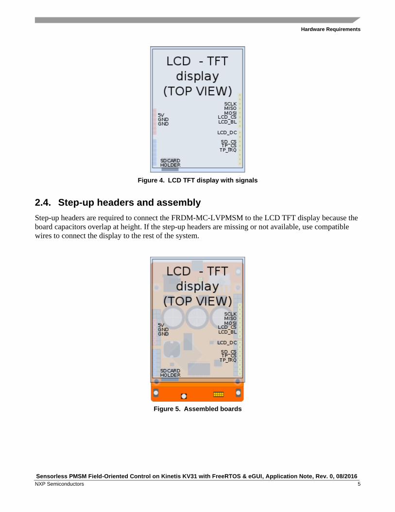
2.3. Arduino LCD TFT shield
The LCD TFT display turns the embedded demo application into a user-friendly platform which
displays the application states and other required parameters or values in real time. For these purposes,
an Arduino-compatible display shield that contains a graphical driver for driving a 320x240 display with
mounted voltage regulators and backlight control is used. The board also contains support for touch
sensing and has an SD card slot; both can communicate via SPI. The following figure shows the
available pins used on the board. The method of display operation is described in Section 5.1,
“Graphical library”.
Hardware Requirements
Sensorless PMSM Field-Oriented Control on Kinetis KV31 with FreeRTOS & eGUI, Application Note, Rev. 0, 08/2016
NXP Semiconductors 5
Figure 4. LCD TFT display with signals
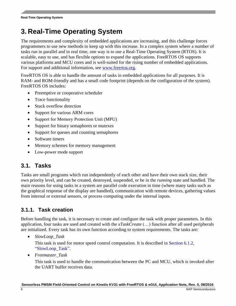
2.4. Step-up headers and assembly
Step-up headers are required to connect the FRDM-MC-LVPMSM to the LCD TFT display because the
board capacitors overlap at height. If the step-up headers are missing or not available, use compatible
wires to connect the display to the rest of the system.
Figure 5. Assembled boards
Real-Time Operating System
Sensorless PMSM Field-Oriented Control on Kinetis KV31 with FreeRTOS & eGUI, Application Note, Rev. 0, 08/2016
6 NXP Semiconductors
3. Real-Time Operating System
The requirements and complexity of embedded applications are increasing, and this challenge forces
programmers to use new methods to keep up with this increase. In a complex system where a number of
tasks run in parallel and in real time, one way is to use a Real-Time Operating System (RTOS). It is
scalable, easy to use, and has flexible options to expand the applications. FreeRTOS OS supports
various platforms and MCU cores and is well-suited for the rising number of embedded applications.
For support and additional information, see www.freertos.org.
FreeRTOS OS is able to handle the amount of tasks in embedded applications for all purposes. It is
RAM- and ROM-friendly and has a small code footprint (depends on the configuration of the system).
FreeRTOS OS includes:
Preemptive or cooperative scheduler
Trace functionality
Stack overflow detection
Support for various ARM cores
Support for Memory Protection Unit (MPU)
Support for binary semaphores or mutexes
Support for queues and counting semaphores
Software timers
Memory schemes for memory management
Low-power mode support
3.1. Tasks
Tasks are small programs which run independently of each other and have their own stack size, their
own priority level, and can be created, destroyed, suspended, or be in the running state and handled. The
main reasons for using tasks in a system are parallel code execution in time (where many tasks such as
the graphical response of the display are handled), communication with remote devices, gathering values
from internal or external sensors, or process computing under the internal inputs.
3.1.1. Task creation
Before handling the task, it is necessary to create and configure the task with proper parameters. In this
application, four tasks are used and created with the xTaskCreate (…) function after all used peripherals
are initialized. Every task has its own function according to system requirements. The tasks are:
SlowLoop_Task
This task is used for motor speed control computation. It is described in Section 6.1.2,
“SlowLoop_Task”.
Freemaster_Task
This task is used to handle the communication between the PC and MCU, which is invoked after
the UART buffer receives data.

Real-Time Operating System
Sensorless PMSM Field-Oriented Control on Kinetis KV31 with FreeRTOS & eGUI, Application Note, Rev. 0, 08/2016
NXP Semiconductors 7
DemoMode_Task
This task checks the press state of the SW2 on-board button which controls the demonstration
mode of the motor spinning and turns it on or off.
Display_Task
This task handles the graphical response of the application state to the TFT LCD display. This
task runs in the infinite loop and is called every 25 Hz.
The tasks can be run either periodically or asynchronously, which may be invoked from the internal
process or interrupt. The periodic tasks are executed with a periodic frequency, such as the
SlowLoop_Task, Display_Task, and DemoMode_Task. Asynchronous or not, the periodically-executed
task is invoked from an interrupt or from another task. Freemaster_Task is invoked from the UART
interrupt and is selected as an asynchronous task.
3.1.2. Task handling
Only one task is running at a time, but the application contains several tasks which are inactive (in the
not running state). The scheduler can turn one task to the not running (inactive) state and another to the
running state. This is a fundamental functionality of an RTOS where several tasks are switched between
two possible states (running or not running). Figure 6a shows a true task code execution, possible in
multicore systems. The embedded device used has one core, so only one task can be executed at a time.
Figure 6b shows a process where Task A is executed. At the end of Task A, the scheduler switches the
execution code of Task B (running state). Task A is then switched to the not running state, and so on.
All tasks have the same priority level and the same execution window time. The fast switching between
all tasks is near to a parallel execution of code.
Figure 6. Code execution
Every task has a time slice to perform its action. At the end of a time slice, the scheduler is called and
the next task that is ready to run is executed. The previous task is put to the not running state. For this
purpose, a periodic interrupt provided by the hardware timer is used (such as SysTick). In this
application, the time slice is defined as an interrupt frequency in configTICK_RATE_HZ, as 1000 Hz, or
1 ms. If the task requires more time to perform its action and another task is not required to run because
it is not ready, the task is interrupted using SysTick. It can continue to operate until it is done or until a
next interrupt occurs. The task frequency must be set to a lower value by the in-system delay function.
Real-Time Operating System
Sensorless PMSM Field-Oriented Control on Kinetis KV31 with FreeRTOS & eGUI, Application Note, Rev. 0, 08/2016
8 NXP Semiconductors
If there is no ready task waiting in the queue to be run, the IDLE task is created or hooked and switched
by the scheduler.
3.1.3. Task scheduling
The task content can be switched at a maximum speed of the configTICK_RATE_HZ definition. Some
applications may require a slower task switching than the defined maximum. A task delay function with
the vTaskDelay(value / (portTICK_PERIOD_MS)) parameter must be used for the time delay. A value is
a time parameter defined in ms. This configuration provides a delay function. The task is called and
executed in a defined frequency which depends on the parameter value, and is calculated from the core
speed.
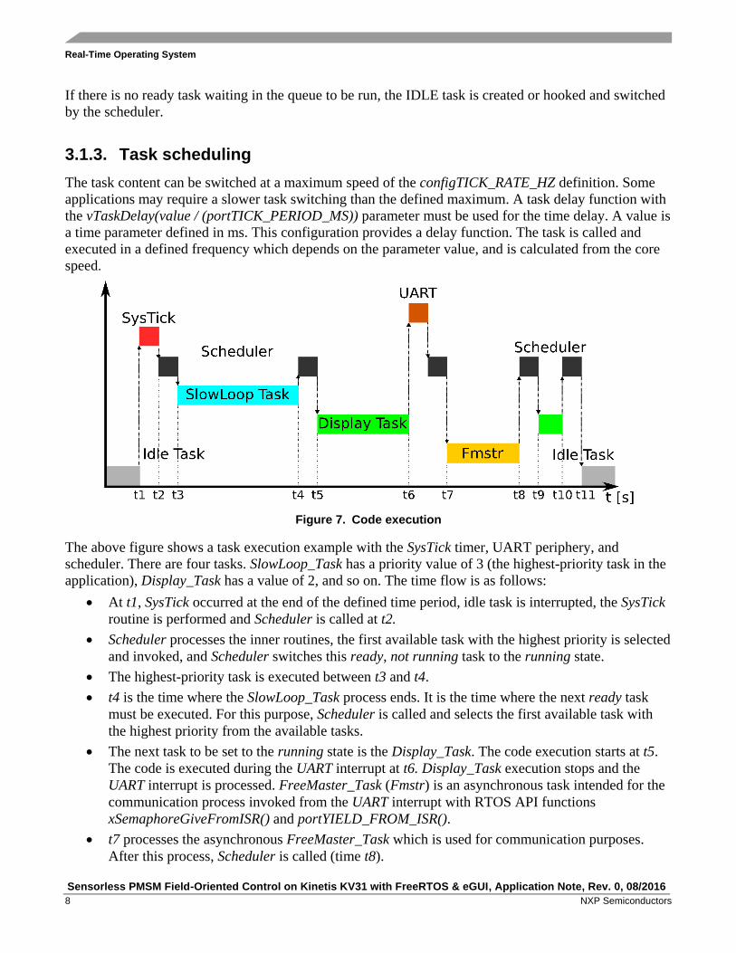
Figure 7. Code execution
The above figure shows a task execution example with the SysTick timer, UART periphery, and
scheduler. There are four tasks. SlowLoop_Task has a priority value of 3 (the highest-priority task in the
application), Display_Task has a value of 2, and so on. The time flow is as follows:
At t1, SysTick occurred at the end of the defined time period, idle task is interrupted, the SysTick
routine is performed and Scheduler is called at t2.
Scheduler processes the inner routines, the first available task with the highest priority is selected
and invoked, and Scheduler switches this ready, not running task to the running state.
The highest-priority task is executed between t3 and t4.
t4 is the time where the SlowLoop_Task process ends. It is the time where the next ready task
must be executed. For this purpose, Scheduler is called and selects the first available task with
the highest priority from the available tasks.
The next task to be set to the running state is the Display_Task. The code execution starts at t5.
The code is executed during the UART interrupt at t6. Display_Task execution stops and the
UART interrupt is processed. FreeMaster_Task (Fmstr) is an asynchronous task intended for the
communication process invoked from the UART interrupt with RTOS API functions
xSemaphoreGiveFromISR() and portYIELD_FROM_ISR().
t7 processes the asynchronous FreeMaster_Task which is used for communication purposes.
After this process, Scheduler is called (time t8).

Real-Time Operating System
Sensorless PMSM Field-Oriented Control on Kinetis KV31 with FreeRTOS & eGUI, Application Note, Rev. 0, 08/2016
NXP Semiconductors 9
t8 and t9 define a time when Scheduler is processed. The next task is selected and preempted.
Display_Task is resumed, set to the running state, and executed at time t10.
Scheduler is processed, all available tasks in the queue are processed, and Idle_Task is created
(or hooked) and processed at t11.
3.2. Interrupt processing
Figure 7 shows the process with the UART interrupt event which invokes FreeMaster_Task.
The interrupts may be as short as possible due to the system performance. The interrupts only handle the
necessary communication data. Further data processing is done by FreeMaster_Task.
The RTOS system may use several possible mechanisms to handle external interrupts. One of the
available methods to synchronize the interrupt with the task is the binary semaphore. The binary
semaphore is used for synchronization between events. It can be used to unblock a task if an interrupt or
event occurs. A task can be in a blocked state instead of being called periodically with the scheduler.
When an interrupt occurs, the necessary data are processed in an interrupt and the process is deferred to
a task. Two RTOS API functions are used: xSemaphoreGiveFromISR(), which “gives” a semaphore
from the particular interrupt, and xSemaphoreTake(), which “takes” a semaphore. The Scheduler switch
is forced using portYIELD_FROM_ISR(), its content switches from an interrupt to a task, the semaphore
is taken, and the task re-enters the blocked state.
Figure 8. Semaphore flow
The above figure shows the process where the task is in the blocked—not running state until it is
unblocked by a semaphore. An interrupt event occurs, the semaphore is given via a mechanism to a task
which is then unblocked, the semaphore is “taken”, and the task runs. After that, the semaphore is
released and the task is set to the blocked state, where it waits for a new event.
The RTOS API safe functions may be used in the UART interrupt if the priority is equal to or lower than
configLIBRARY_MAX_SYSCALL_INTERRUPT_PRIORITY.

Real-Time Operating System
Sensorless PMSM Field-Oriented Control on Kinetis KV31 with FreeRTOS & eGUI, Application Note, Rev. 0, 08/2016
10 NXP Semiconductors
3.3. Memory management and stack
The RTOS can use four available RAM-allocation schemes prepared to handle a memory allocation.
Every time a task, queue, or semaphore is created, a part of the RAM memory is required and consumed
by the RTOS system. This space is HEAP and its size is defined as configTOTAL_HEAP_SIZE. When a
task is created, the amount of memory consumed is configMINIMAL_STACK_SIZE or defined by the user.
This memory is taken from the HEAP space, and also its size is specific for the application. The HEAP
scheme is defined in the source code, where four possible implementations are available, but only one of
them must be used.
The selected HEAP scheme 1 is suitable for most applications. It is the simplest scheme and allows for
memory allocation (but not for memory freeing). The allocated memory can’t be freed during the
application operation. This memory scheme can be used if a task or queue is never deleted.
This scheme is:
Deterministic
Suitable for a system that never deletes tasks or queues
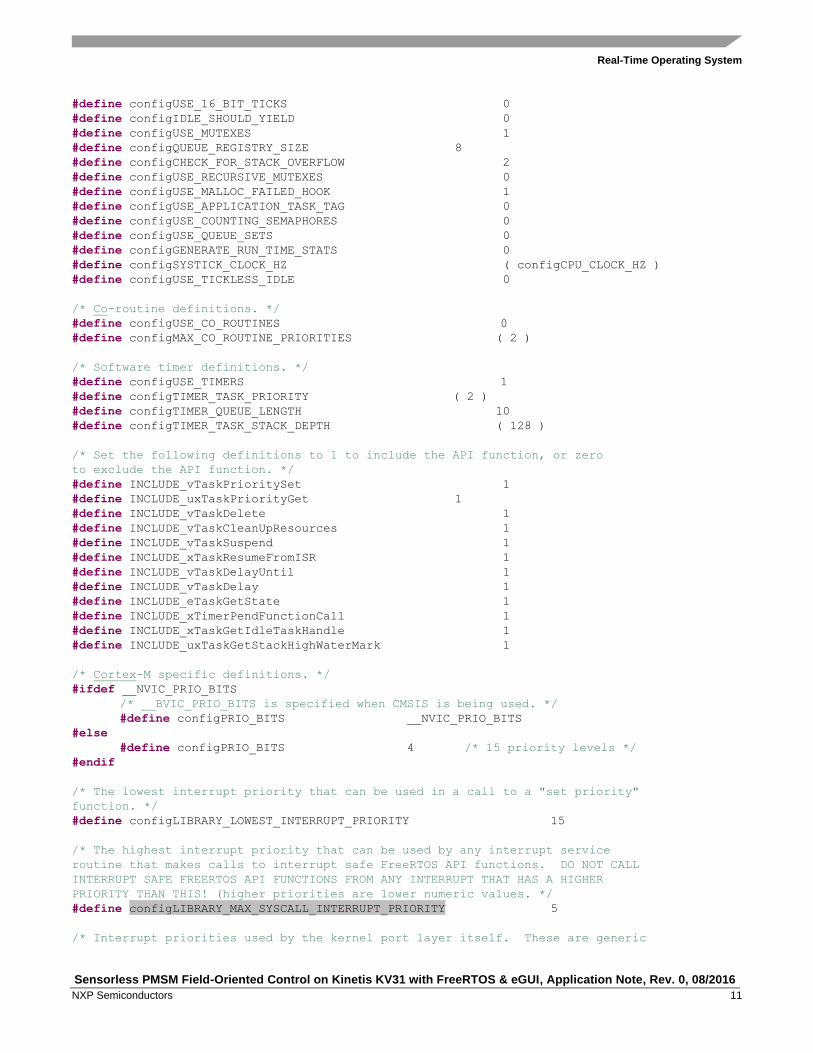
3.4. RTOS configuration
The RTOS configuration used in a particular application is shown in the following example and it can be
also found in the FreeRTOSConfig.h source file.
Example 1. RTOS configuration
#ifndef FREERTOS_CONFIG_H
#define FREERTOS_CONFIG_H
#include "fsl_device_registers.h"
/*-----------------------------------------------------------
* Application specific definitions.
*
* These definitions should be adjusted for your particular hardware and
* application requirements.
*
* THESE PARAMETERS ARE DESCRIBED WITHIN THE 'CONFIGURATION' SECTION OF THE
* FreeRTOS API DOCUMENTATION AVAILABLE ON THE FreeRTOS.org WEB SITE.
*
* See http://www.freertos.org/a00110.html.
*----------------------------------------------------------*/
/* Ensure stdint is only used by the compiler, and not the assembler. */
#define configUSE_PREEMPTION 1
#define configUSE_PORT_OPTIMISED_TASK_SELECTION 1
#define configUSE_IDLE_HOOK 1
#define configUSE_TICK_HOOK 0
#define configCPU_CLOCK_HZ ( DEFAULT_SYSTEM_CLOCK )
#define configTICK_RATE_HZ ( (TickType_t) 1000 )
#define configMAX_PRIORITIES ( 6 )
#define configMINIMAL_STACK_SIZE ( 256 )
#define configTOTAL_HEAP_SIZE ( ( size_t ) ( 8 * 1024 ) )
#define configMAX_TASK_NAME_LEN ( 5 )
#define configUSE_TRACE_FACILITY 1
Real-Time Operating System
Sensorless PMSM Field-Oriented Control on Kinetis KV31 with FreeRTOS & eGUI, Application Note, Rev. 0, 08/2016
NXP Semiconductors 11
#define configUSE_16_BIT_TICKS 0
#define configIDLE_SHOULD_YIELD 0
#define configUSE_MUTEXES 1
#define configQUEUE_REGISTRY_SIZE 8
#define configCHECK_FOR_STACK_OVERFLOW 2
#define configUSE_RECURSIVE_MUTEXES 0
#define configUSE_MALLOC_FAILED_HOOK 1
#define configUSE_APPLICATION_TASK_TAG 0
#define configUSE_COUNTING_SEMAPHORES 0
#define configUSE_QUEUE_SETS 0
#define configGENERATE_RUN_TIME_STATS 0
#define configSYSTICK_CLOCK_HZ ( configCPU_CLOCK_HZ )
#define configUSE_TICKLESS_IDLE 0
/* Co-routine definitions. */
#define configUSE_CO_ROUTINES 0
#define configMAX_CO_ROUTINE_PRIORITIES ( 2 )
/* Software timer definitions. */
#define configUSE_TIMERS 1
#define configTIMER_TASK_PRIORITY ( 2 )
#define configTIMER_QUEUE_LENGTH 10
#define configTIMER_TASK_STACK_DEPTH ( 128 )
/* Set the following definitions to 1 to include the API function, or zero
to exclude the API function. */
#define INCLUDE_vTaskPrioritySet 1
#define INCLUDE_uxTaskPriorityGet 1
#define INCLUDE_vTaskDelete 1
#define INCLUDE_vTaskCleanUpResources 1
#define INCLUDE_vTaskSuspend 1
#define INCLUDE_xTaskResumeFromISR 1
#define INCLUDE_vTaskDelayUntil 1
#define INCLUDE_vTaskDelay 1
#define INCLUDE_eTaskGetState 1
#define INCLUDE_xTimerPendFunctionCall 1
#define INCLUDE_xTaskGetIdleTaskHandle 1
#define INCLUDE_uxTaskGetStackHighWaterMark 1
/* Cortex-M specific definitions. */
#ifdef __NVIC_PRIO_BITS
/* __BVIC_PRIO_BITS is specified when CMSIS is being used. */
#define configPRIO_BITS __NVIC_PRIO_BITS
#else
#define configPRIO_BITS 4 /* 15 priority levels */
#endif
/* The lowest interrupt priority that can be used in a call to a "set priority"
function. */
#define configLIBRARY_LOWEST_INTERRUPT_PRIORITY 15
/* The highest interrupt priority that can be used by any interrupt service
routine that makes calls to interrupt safe FreeRTOS API functions. DO NOT CALL
INTERRUPT SAFE FREERTOS API FUNCTIONS FROM ANY INTERRUPT THAT HAS A HIGHER
PRIORITY THAN THIS! (higher priorities are lower numeric values. */
#define configLIBRARY_MAX_SYSCALL_INTERRUPT_PRIORITY 5
/* Interrupt priorities used by the kernel port layer itself. These are generic

Motor Control
Sensorless PMSM Field-Oriented Control on Kinetis KV31 with FreeRTOS & eGUI, Application Note, Rev. 0, 08/2016
12 NXP Semiconductors
to all Cortex-M ports, and do not rely on any particular library functions. */
#define configKERNEL_INTERRUPT_PRIORITY (
configLIBRARY_LOWEST_INTERRUPT_PRIORITY << (8 - configPRIO_BITS) )
/* !!!! configMAX_SYSCALL_INTERRUPT_PRIORITY must not be set to zero !!!!
See http://www.FreeRTOS.org/RTOS-Cortex-M3-M4.html. */
#define configMAX_SYSCALL_INTERRUPT_PRIORITY ( configLIBRARY_MAX_SYSCALL_INTERRUPT_PRIORITY
<< (8 - configPRIO_BITS) )
/* Normal assert() semantics without relying on the provision of an assert.h
header file. */
#define configASSERT( x ) if( ( x ) == 0 ) { taskDISABLE_INTERRUPTS(); for( ;; ); }
/* Definitions that map the FreeRTOS port interrupt handlers to their CMSIS
standard names. */
#define vPortSVCHandler SVC_Handler
#define xPortPendSVHandler PendSV_Handler
#define xPortSysTickHandler SysTick_Handler
#endif /* FREERTOS_CONFIG_H */
4. Motor Control
The motor-control part is based on the Motor Control Reference Solution Package (MCRSP) software
for a 3-phase Permanent Magnet Synchronous Motor (PMSM). The included motor-parameter
identification algorithms can run on the 32-bit Kinetis V series MCUs. See Sensorless PMSM
Field-Oriented Control on Kinetis KV (document AN5237) for more details about the configuration or
driving of motors.
4.1. 3-phase PMSM
Sinusoidal PMSMs are popular due to good efficiency, low acoustic noise, and low torque ripple which
is most efficient when driven by the Vector Control (VC) or Field-Oriented Control (FOC). The FOC
technique brings overall improvements in drive (high efficiency, full torque control from zero to
nominal motor speed, decoupled control of flux and torque, improved dynamics, and so on). For the
PMSM control, it is necessary to know the exact rotor position. This application uses special algorithms
to estimate the speed and position instead of using a physical position sensor.
4.2. Application concept
For a full torque control of a PMSM motor, know various parameters (such as the DC voltage and
current values for each phase) to calculate the rotor position and speed. The other parameters that are
required for full motor driving are phase inductance, resistance, rotor flux, number of poles, and more.
They are measured using the Motor Control Application Tuning (MCAT) tool and described in Motor
Control Application Tuning (MCAT) Tool for 3-Phase PMSM (document AN4642). A precise timing
and value measurement is required because the maximal torque is achieved when the rotor magnetic flux
and the stator magnetic flux are perpendicular to each other. The FOC is used for this purpose. The full
driving principle is described in Sensorless PMSM Field-Oriented Control (document DRM148). The
example is based on a framework model which uses two main loops for motor driving. The fast loop
serves for value measurements (currents, voltages), fault protection, and calculation of the optimal

Motor Control
Sensorless PMSM Field-Oriented Control on Kinetis KV31 with FreeRTOS & eGUI, Application Note, Rev. 0, 08/2016
NXP Semiconductors 13
stator-rotor position. A precise timing is required, so the ADC interrupt must handle this. The speed loop
handles the required speed.
4.3. Control theory
A 3-phase motor has a 3-phase winding connected to the FRDM-MC-LVPMSM shield. It also contains
six power N-MOS transistors (two for each phase). The main principle is to create a 3-phase AC voltage
on the motor windings. The PWM module of the KV31 MCU is used for this purpose. A correct
switching of the six N-MOS transistors generates a 3-phase AC voltage that causes the rotation of the
motor. The key is to have a precise measurement of the phase currents for FOC computing in a time
where the measure does not affect the transient event. The current measurement is processed in the
middle of the PWM duty cycle where the measurement may not be affected. The PWM reload generates
a hardware trigger for the Programmable Delay Block (PDB) periphery. The PDB generates the
pre-triggers for the ADCs in the back-to-back mode delayed approximately Tdeadtime/2 after the PWM
reload. When the second (last) sample conversion is completed, the ADC generates an interrupt for the
motor-control fast loop.
Figure 9. Code execution
The phase-current measurement and FOC computing are processed in the ADC_ISR handler (see Figure
9). This interrupt has the highest priority in the application due to phase measurement, fault checking,
computing of rotor position, computing of space vectors, and updating the duty cycles of the PWM
periphery. The highest priority is needed for a precise application timing which is required in motor-
control applications. The motor-control part is divided into two blocks. The first block is the important,
non-breakable fast control loop which includes the described parts. The second block is the slow control
loop which has a lower priority than the fast loop and is used to compute the speed of the motor (see the
following figure).

System Parts
Sensorless PMSM Field-Oriented Control on Kinetis KV31 with FreeRTOS & eGUI, Application Note, Rev. 0, 08/2016
14 NXP Semiconductors
Figure 10. Code execution
The fast control loop is processed in the ADC interrupt with the highest priority and must not be
preempted with other interrupts or events. The execution period is defined as the PWM frequency.
The slow control loop has lower priority than the fast control loop and can be preempted. The frequency
of the operation typically ranges from 1 ms to 10 ms (depending on the system). This allows to move the
slow control loop as a task in the RTOS system.
5. System Parts
The system uses two additional parts: eGUI graphical library and FreeMASTER debugging tool. Both of
them have their respective application notes that describe their functions, implementations, and
possibilities which can be useful for future system extension. The system concept is described in detail
in the following sections.
5.1. Graphical library
The communication between the MCU board and the graphical display is done using a serial SPI
periphery. It reduces the count of used pins to five plus a backlight-control pin for the background
brightness. This configuration is suitable for a system where the display response is not very fast but
requires a single external graphic driver to handle a 320x240 RGB display. The used display shield has
the HX8347 graphical driver which enables full display control and has an amount of internal settings to
be configured before using the display.
5.1.1. eGUI
The display is driven by eGUI software (an object-based open-source graphical framework suitable to
drive graphical displays). eGUI supports several graphical ICs and touch-screen and communication
peripherals, such as SPI (used) and SD card. eGUI can draw various objects such as gauges, textboxes,
System Parts
Sensorless PMSM Field-Oriented Control on Kinetis KV31 with FreeRTOS & eGUI, Application Note, Rev. 0, 08/2016
NXP Semiconductors 15
labels, bitmap images, and other. eGUI can also draw simple objects such as lines, boxes, circles, and
other. It is targeted for devices with a small RAM footprint. All necessary code is stored in the MCU’s
flash and its size is based on the objects used.
eGUI uses a standard file structure and functions described in Freescale Embedded GUI (D4D)
(document DRM116) which contains additional information about functions, parameters, graphical
objects, and more.
5.1.2. Graphical components
The graphical objects used are defined in the eGUI source code. Several objects must be drawn on the
display according to the definitions in the configuration files which are described below. The files that
define the behavior of the application are located in the src/D4Di/common_source folder:
d4d_screen_entry.c—graphical object declaration
d4d_user_cfg_app.h—driver user configuration file
d4d_user_cfg.h—user configuration file (for example, to define the LCD driver and
communication plugin used)
d4dlcdhw_kinetis_spi_cfg.h—SPI configuration
fonts.c—font data
picture.c—background and gauge image data
Selecting the low-level drivers required for communication, the hardware communication profile is
defined in the src/D4D/low_level_drivers/ folder:
The lcd_controllers_drivers/hx8347/* folder contains low-level routines for handling LCD
displays.
The lcd_hw_interface/kinetis_spi_bm/* folder contains routines for SPI initialization functions
compatible with the eGUI framework.
5.1.3. Screen draw
All objects to be drawn on the LCD display are defined in the d4d_screen_entry.c source file. The used
driver and the communication peripherals are defined in the d4d_user_cfg.h file. After the objects and
functions are properly defined, the display initialization routine D4D_Init(&screen_entry) is called with
the screen_entry parameter. This routine initializes the SPI communication driver and routines for
communication with the graphical driver, performs a screen initialization, and the screen objects are then
drawn on the display.
FreeRTOS and Motor Control Implementation
Sensorless PMSM Field-Oriented Control on Kinetis KV31 with FreeRTOS & eGUI, Application Note, Rev. 0, 08/2016
16 NXP Semiconductors
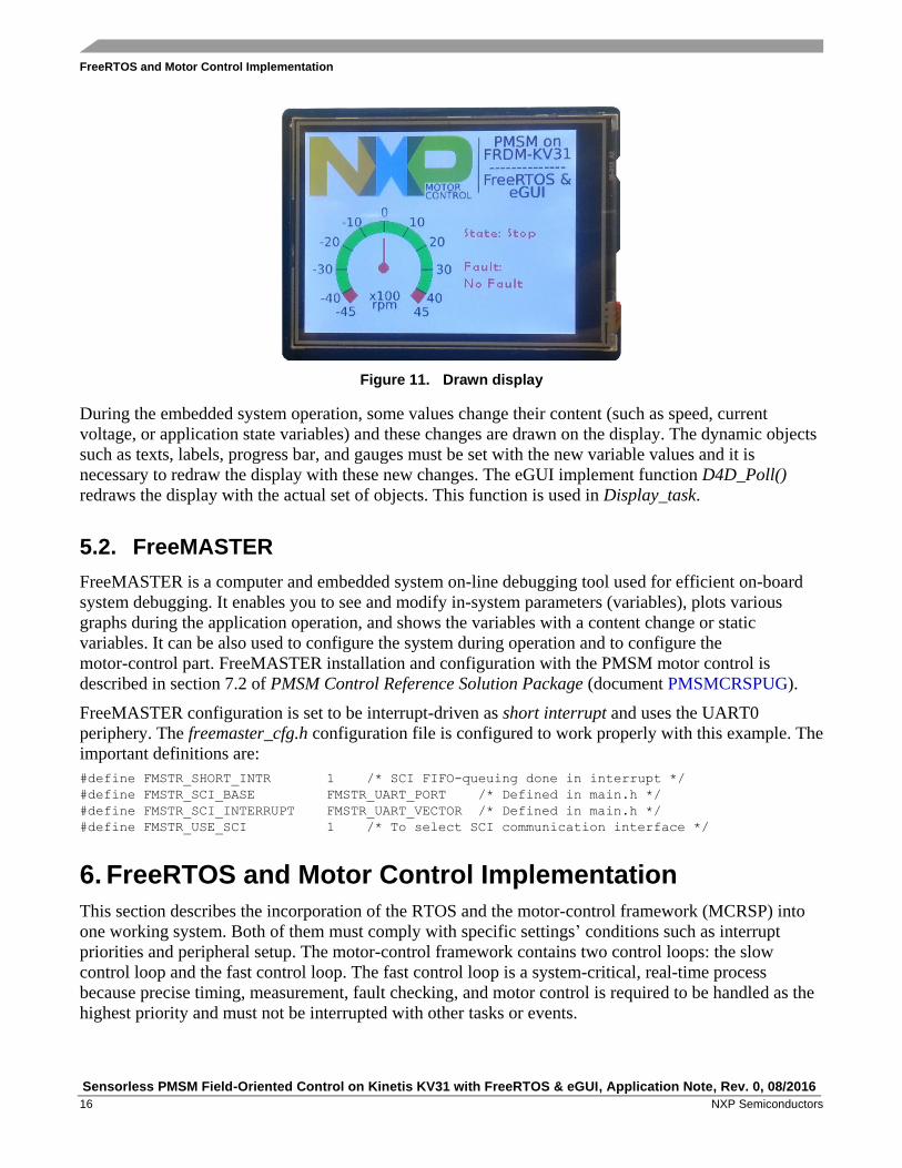
Figure 11. Drawn display
During the embedded system operation, some values change their content (such as speed, current
voltage, or application state variables) and these changes are drawn on the display. The dynamic objects
such as texts, labels, progress bar, and gauges must be set with the new variable values and it is
necessary to redraw the display with these new changes. The eGUI implement function D4D_Poll()
redraws the display with the actual set of objects. This function is used in Display_task.
5.2. FreeMASTER
FreeMASTER is a computer and embedded system on-line debugging tool used for efficient on-board
system debugging. It enables you to see and modify in-system parameters (variables), plots various
graphs during the application operation, and shows the variables with a content change or static
variables. It can be also used to configure the system during operation and to configure the
motor-control part. FreeMASTER installation and configuration with the PMSM motor control is
described in section 7.2 of PMSM Control Reference Solution Package (document PMSMCRSPUG).
FreeMASTER configuration is set to be interrupt-driven as short interrupt and uses the UART0
periphery. The freemaster_cfg.h configuration file is configured to work properly with this example. The
important definitions are:
#define FMSTR_SHORT_INTR 1 /* SCI FIFO-queuing done in interrupt */
#define FMSTR_SCI_BASE FMSTR_UART_PORT /* Defined in main.h */
#define FMSTR_SCI_INTERRUPT FMSTR_UART_VECTOR /* Defined in main.h */
#define FMSTR_USE_SCI 1 /* To select SCI communication interface */
6. FreeRTOS and Motor Control Implementation
This section describes the incorporation of the RTOS and the motor-control framework (MCRSP) into
one working system. Both of them must comply with specific settings’ conditions such as interrupt
priorities and peripheral setup. The motor-control framework contains two control loops: the slow
control loop and the fast control loop. The fast control loop is a system-critical, real-time process
because precise timing, measurement, fault checking, and motor control is required to be handled as the
highest priority and must not be interrupted with other tasks or events.

FreeRTOS and Motor Control Implementation
Sensorless PMSM Field-Oriented Control on Kinetis KV31 with FreeRTOS & eGUI, Application Note, Rev. 0, 08/2016
NXP Semiconductors 17
The slow control loop is not necessarily a system-critical process that must be incorruptible and it must
be managed as an RTOS process. The implementation of both systems into an embedded system is
shown in this figure:
Figure 12. Embedded system
6.1. Program flow
The program flow is very important in embedded software designs. It is a process where the functions
and system components are initialized and the other parts of the system are processed. Right after a
device reset, the internal core and memory components are initialized, the clock configuration is set, and
the main routine is started. The following sections show the program flow for the main function, four
tasks, and the motor-control part.
6.1.1. Main initialization
The main routine-initialization functions are performed after any device reset, called only once, and they
never reach the endless for loop. The task management is handled by the RTOS system and the system
interrupts are handled on their own. The scheduler starts after the initialization of internal registers,
clocks, and other modules is completed. The following figure shows the main routine flowchart after the
MCU reset.

FreeRTOS and Motor Control Implementation
Sensorless PMSM Field-Oriented Control on Kinetis KV31 with FreeRTOS & eGUI, Application Note, Rev. 0, 08/2016
18 NXP Semiconductors
Figure 13. Main routine flow
6.1.2. SlowLoop_Task
SlowLoop_Task is a task which processes the speed-control loop of the driven motor. SlowLoop_Task is
implemented as a task handled by the RTOS system because the time resolution is set to 1 ms, which is
a sufficient period for the motor dynamic control. SlowLoop_Task uses the SM_StateMachineSlow()
function (it is a part of the motor-control algorithms solution). This task is called periodically at a
maximum possible frequency defined with the highest priority level. The SlowLoop_Task flowchart is
shown in this figure:
Figure 14. SlowLoop_Task flowchart
FreeRTOS and Motor Control Implementation
Sensorless PMSM Field-Oriented Control on Kinetis KV31 with FreeRTOS & eGUI, Application Note, Rev. 0, 08/2016
NXP Semiconductors 19
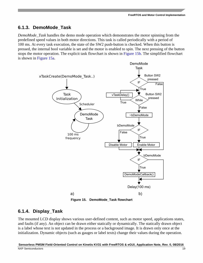
6.1.3. DemoMode_Task
DemoMode_Task handles the demo mode operation which demonstrates the motor spinning from the
predefined speed values in both motor directions. This task is called periodically with a period of
100 ms. At every task execution, the state of the SW2 push-button is checked. When this button is
pressed, the internal bool variable is set and the motor is enabled to spin. The next pressing of the button
stops the motor operation. The explicit task flowchart is shown in Figure 15b. The simplified flowchart
is shown in Figure 15a.
Figure 15. DemoMode_Task flowchart
6.1.4. Display_Task
The mounted LCD display shows various user-defined content, such as motor speed, applications states,
and faults (if any). An object can be drawn either statically or dynamically. The statically drawn object
is a label whose text is not updated in the process or a background image. It is drawn only once at the
initialization. Dynamic objects (such as gauges or label texts) change their values during the operation.

FreeRTOS and Motor Control Implementation
Sensorless PMSM Field-Oriented Control on Kinetis KV31 with FreeRTOS & eGUI, Application Note, Rev. 0, 08/2016
20 NXP Semiconductors
The dynamic objects are redrawn dynamically with Display_Task at a frequency of 25 ms, which is a
sufficient period for a smooth display refreshing. For a better performance, the gauge that shows the
actual motor speed is refreshed at every task execution (25 ms), while the application and fault statuses
are refreshed only after their values change. The high-level task flowchart is shown in Figure 16a and
the detailed flowchart is shown in Figure 16b.
Figure 16. Display_Task flowchart
6.1.5. FreeMaster_Task
FreeMaster_Task has the second lowest task priority above the IDLE process. It is not executed
periodically (as the other tasks), but it is invoked from the UART interrupt. The task is performed only
after the communication data are received from the FreeMASTER computer side. The task is blocked by
a semaphore during the remaining time. The task is unblocked by the semaphore mechanism after the
data are received by the internal FIFO register of the UART periphery (while the interrupts are enabled).
The UART handler occurs, the FMSTR_Isr() function is called, and the data from the UART FIFO
register are stored in the internal FreeMASTER structure. The full communication process is performed
in the task which must be unblocked by the xSemaphoreGiveFromISR() function and the content is
switched to a proper task. Figure 17a shows the task and semaphore initialization. Figure 17b shows the
casual process flow.

FreeRTOS and Motor Control Implementation
Sensorless PMSM Field-Oriented Control on Kinetis KV31 with FreeRTOS & eGUI, Application Note, Rev. 0, 08/2016
NXP Semiconductors 21
Figure 17. FreeMaster_Task flowchart
6.1.6. Fast loop process—ADC interrupt
Fast loops are processed outside of the RTOS system and they are not affected by other interrupts.
The execution period is defined as a macro for the FlexTimer periphery and is set to 100 s (10 kHz).
This task processes the measurement, calculations, and functions for the fault detections.

FreeRTOS and Motor Control Implementation
Sensorless PMSM Field-Oriented Control on Kinetis KV31 with FreeRTOS & eGUI, Application Note, Rev. 0, 08/2016
22 NXP Semiconductors
Figure 18. Fast loop flowchart
6.1.7. Programmable Delay Block (PDB)
This interrupt has the second highest priority after the ADC module. Is not directly used to handle any of
the operations, but it is required when an error occurs in the ADC module measurement process.
6.2. Interrupt configuration
Interrupts are an integral part of modern real-time embedded systems and can respond to internal or
external events and handle them. Interrupts are used in real-time systems where precise timing is critical
(for example current measurement). The KV31 MCU’s core is ARM Cortex CM4F with lots of
possibilities in the interrupt settings. By default, the ARM core supports up to 255 interrupt priorities
and 8 bits in the register. The manufacturer can also implement a lower value of available interrupts’
levels. The KV31F MCU supports 4 bits of interrupts or 16 values (from 0 to 15).
Correct interrupt settings are important for a good concurrent running of two parts. The RTOS system
uses the interrupt-driven SysTick timer to handle tasks, while the motor-control part calls the fast-loop
interrupt. The motor-control fast loop has higher priority than the RTOS system and must have the
highest priority in the whole system. Don’t get confused by the task priorities, they have their own set of
priorities defined in the RTOS system.
This provides the possibility to set correct interrupts for the whole system, sorted from the highest
priorities to the lowest priorities:
Motor-control fast loop—highest priority
Programmable Delay Block (PDB)
RTOS system call
UART periphery
RTOS kernel—lowest priority

FreeRTOS and Motor Control Implementation
Sensorless PMSM Field-Oriented Control on Kinetis KV31 with FreeRTOS & eGUI, Application Note, Rev. 0, 08/2016
NXP Semiconductors 23
A set of priorities for the used peripherals or system implementations must be configured via the CMSIS
macro NVIC_SetPriority (IRQn, priority) and enabled by NVIC_EnableIRQ(IRQn). All peripherals that
have the ability to interrupt have a value of 0—highest default priority. The peripherals must be
configured to work properly. The following figure shows the defined priority levels in an application
where the RTOS system has a priority level of 5 and below. The motor-control part has a priority level
of 4 and above and it is not affected by the RTOS system which results in an improved response and a
precise timing of the motor-control application part.
Figure 19. Code execution
The FreeRTOSConfig.h file defines the maximum and minimum priority levels for the RTOS. The
interrupts below this value can use the RTOS interrupt safe routines. The interrupt safe function higher
than this value must not be used.
#define configLIBRARY_MAX_SYSCALL_INTERRUPT_PRIORITY (5)
The kernel interrupt priority is set as:
#define configLIBRARY_LOWEST_INTERRUPT_PRIORITY (15)
The motor-control interrupt definition based on the FreeRTOSConfig.h definitions is:
NVIC_EnableIRQ(ADC1_IRQn); /* Enable Interrupt */
NVIC_SetPriority(ADC1_IRQn, configLIBRARY_MAX_SYSCALL_INTERRUPT_PRIORITY - 3);
NVIC_EnableIRQ(PDB0_IRQn); /* Enable Interrupt */
NVIC_SetPriority(PDB0_IRQn, configLIBRARY_MAX_SYSCALL_INTERRUPT_PRIORITY - 2);
This definition allows for the critical motor-control part to be unaffected by the RTOS system. The
RTOS scheduler latency is not critical so the other parts (such as speed control loop or communication)
can be managed by the system. The code execution time line is shown in the following figure.
Conclusion
Sensorless PMSM Field-Oriented Control on Kinetis KV31 with FreeRTOS & eGUI, Application Note, Rev. 0, 08/2016
24 NXP Semiconductors
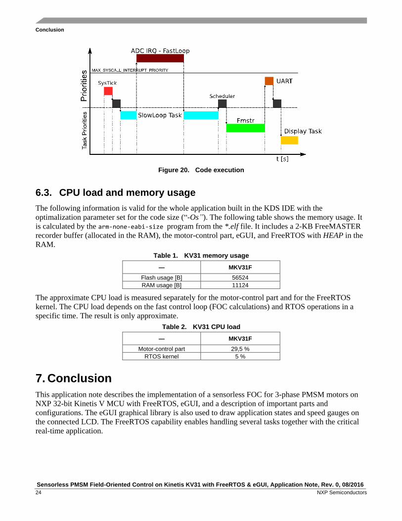
Figure 20. Code execution
6.3. CPU load and memory usage
The following information is valid for the whole application built in the KDS IDE with the
optimalization parameter set for the code size (“-Os”). The following table shows the memory usage. It
is calculated by the arm-none-eabi-size program from the *.elf file. It includes a 2-KB FreeMASTER
recorder buffer (allocated in the RAM), the motor-control part, eGUI, and FreeRTOS with HEAP in the
RAM.
Table 1. KV31 memory usage
— MKV31F
Flash usage [B] 56524
RAM usage [B] 11124
The approximate CPU load is measured separately for the motor-control part and for the FreeRTOS
kernel. The CPU load depends on the fast control loop (FOC calculations) and RTOS operations in a
specific time. The result is only approximate.
Table 2. KV31 CPU load
— MKV31F
Motor-control part 29,5 %
RTOS kernel 5 %
7. Conclusion
This application note describes the implementation of a sensorless FOC for 3-phase PMSM motors on
NXP 32-bit Kinetis V MCU with FreeRTOS, eGUI, and a description of important parts and
configurations. The eGUI graphical library is also used to draw application states and speed gauges on
the connected LCD. The FreeRTOS capability enables handling several tasks together with the critical
real-time application.

Revision History
Sensorless PMSM Field-Oriented Control on Kinetis KV31 with FreeRTOS & eGUI, Application Note, Rev. 0, 08/2016
NXP Semiconductors 25
8. Acronyms and Abbreviations Table 3. Acronyms and abbreviations
Term Meaning
AC Alternating Current
ADC Analog-to-Digital Converter
AN Application Note
CPU Central Processing Unit
DRM Design Reference Manual
FOC Field-Oriented Control
FTM FlexTimer Module
I/O Input/Output interfaces between a computer system and the external world—a CPU reads an input to
sense the level of an external signal and writes to an output to change the level of an external signal.
LCD Liquid Crystal Display
MCAT Motor Control Application Tuning tool
MCRSP Motor Control Reference Solution Package
MCU Microcontroller
PDB Programmable Delay Block
PMSM Permanent Magnet Synchronous Machine
PWM Pulse-Width Modulation
RAM Random Access Memory
RTOS Real-Time Operating System
TFT Thin-Film Transistor
UART Universal Asynchronous Receiver/Transmitter
9. References
These references are available on www.nxp.com:
1. Sensorless PMSM Field-Oriented Control (document DRM148)
2. KV31F Sub-Family Reference Manual (document KV31P100M120SF7RM)
3. Sensorless PMSM Field-Oriented Control on Kinetis KV (document AN5237)
4. Motor Control Application Tuning (MCAT) Tool for 3-Phase PMSM (document AN4642)
5. FreeRTOS – online documentation at www.freertos.org
10. Revision History Table 4. Revision history
Revision number Date Substantive changes
0 08/2016 Initial release.

Document Number: AN5309 Rev. 0
08/2016
Information in this document is provided solely to enable system and software
implementers to use NXP products. There are no express or implied copyright licenses
granted hereunder to design or fabricate any integrated circuits based on the
information in this document. NXP reserves the right to make changes without further
notice to any products herein.
NXP makes no warranty, representation, or guarantee regarding the suitability of its
products for any particular purpose, nor does NXP assume any liability arising out of the
application or use of any product or circuit, and specifically disclaims any and all
liability, including without limitation consequential or incidental damages. “Typical”
parameters that may be provided in NXP data sheets and/or specifications can and do
vary in different applications, and actual performance may vary over time. All operating
parameters, including “typicals,” must be validated for each customer application by
customer’s technical experts. NXP does not convey any license under its patent rights
nor the rights of others. NXP sells products pursuant to standard terms and conditions
of sale, which can be found at the following address:
www.nxp.com/SalesTermsandConditions.
NXP, the NXP logo, NXP SECURE CONNECTIONS FOR A SMARTER WORLD,
Freescale, the Freescale logo, Kinetis, and Freedom are trademarks of NXP B.V. All
other product or service names are the property of their respective owners. ARM, the
ARM Powered logo, and Cortex are registered trademarks of ARM Limited (or its
subsidiaries) in the EU and/or elsewhere. All rights reserved.
© 2016 NXP B.V.
How to Reach Us:
Home Page:
www.nxp.com
Web Support:
www.nxp.com/support