sensorless ipmsm control based on an extended nonlinear...
TRANSCRIPT

Journal of Power Electronics, to be published 1
Sensorless IPMSM Control Based on an Extended Nonlinear Observer with Rotational Inertia
Adjustment and Equivalent Flux Error Compensation
Yongle Mao**, Jiaqiang Yang†, Dejun Yin*, and Yangsheng Chen**
†**College of Electrical Engineering, Zhejiang University, Hangzhou, China *School of Mechanical Engineering, Nanjing University of Science and Technology, Nanjing, China
Abstract
Mechanical and electrical parameter uncertainties cause dynamic and static estimation errors of the rotor speed and position, resulting in performance deterioration of sensorless control systems. This paper applies an extended nonlinear observer to interior permanent magnet synchronous motors (IPMSM) for the simultaneous estimation of the rotor speed and position. Two compensation methods are proposed to improve the observer performance against parameter uncertainties: an on-line rotational inertia adjustment approach that employs the gradient descent algorithm to suppress dynamic estimation errors, and an equivalent flux error compensation approach to eliminate static estimation errors caused by inaccurate electrical parameters. The effectiveness of the proposed control strategy is demonstrated by experimental tests. Key words: Interior permanent magnet synchronous motors, Nonlinear observer, Parameter uncertainty, Sensorless control
I. INTRODUCTION
Due to its high torque density, high efficiency, and wide constant-power operating range, the interior permanent magnet synchronous motor (IPMSM) has been extensively used in industrial areas and vehicle propulsions [1]–[2]. However, the high-performance field-oriented control (FOC) systems of IPMSMs require the rotor position information that is generally measured by a mechanical position sensor, e.g. a resolver or an encoder, which is vulnerable to strong vibrations, high operating temperatures, and high humidity. Therefore, various sensorless control schemes have been proposed to eliminate the need for the mechanical position sensors to enhance the system robustness and reduce the manufacturing and maintenance costs [3]–[4].
In the medium to high speed range, model-based sensorless methods are often used due to their high-efficiency and
simplicity, which include back-EMF estimation-based and
observer-based methods. The former is a two-stage sensorless approach, in which, the back-EMF is estimated first, and then the rotor speed and position can be extracted with an arc-tangent or phase-locked-loop (PLL) based on the relationship between the mechanical variables and the back-EMF. In [5]–[6], the back-EMF is directly calculated from voltage equations. Thus, this method is very simple but sensitive to parameter variations and system noise. In [7]–[8], a linear state observer is constructed in the estimated synchronous reference frame to estimate the back-EMF by assuming it to be constant in a sampling period. In [9]–[12], sliding-mode observer (SMO) is employed to estimate the back-EMF in the stator-fixed reference frame. The conventional two-order SMO is very attractive due to its simple algorithm and robustness against rotor flux-linkage uncertainty. However, it suffers from chattering and phase delay problems. In addition, modifications are required to mitigate the chattering of the SMO, such as replacing the signum function with the sigmoid/saturation function or constructing a high-order SMO by taking the current and back-EMF as state variables [11]–[12].
For observer-based sensorless methods, the voltage equation is considered as a reference model, and an adjustable model is formulated by incorporating the estimated unknown mechanical variables. Current estimation errors

2 Journal of Power Electronics, to be published
between the reference and adjustable models are utilized directly to regulate the estimated position/speed. In [13]–[14], a full-order extended Kalman filter (EKF), which is an optimal estimator in the least-square sense, is implemented for speed and position estimation with high reliability. However, the EKF requires complex matrices computations and proper initialization for the covariance matrix. Compared with the EKF, the Model Reference Adaptive System (MRAS) is much simpler. It is employed in [15]–[16] for sensorless control, along with motor parameters simultaneously identified based on an EKF or additional MRAS estimators. Since the rotor position is estimated from the integration of the estimated speed without any adjustment scheme, errors might propagate in sequentially connected estimation loops. In [17], considering parameter uncertainties, three interconnected adaptive observers are designed to simultaneously estimate the rotor position, speed and load-torque, and the stator resistance and inductance, respectively. The observability of the interconnected observers relies on the input persistence property of each subsystem, and observer gains should be judiciously selected for correct convergence. An alternative strategy for the simultaneous estimation of the rotor speed and position is utilizing a nonlinear observer incorporating the motor mechanical model [18]. The state-linearization method is applied in determining the structure of the observer gain matrix for asymptotic convergence. To improve the observer performance against load variations, an extended nonlinear observer is proposed in [19] to estimate the stator current, rotor position and speed, as well as the disturbance torque. Although the nonlinear observer has been extended to IPMSMs in [20] by directly calculating the position dependent inductance induced by the rotor saliency, the implementation process is rather complicated. Moreover, estimation errors of the speed and position will arise if inaccurate mechanical or electrical parameters are adopted in the nonlinear observer.
In this paper, an extended nonlinear observer is applied to IPMSMs based on the “active flux” concept. Considering that the extended nonlinear observer is sensitive to parameter uncertainties, a rotational inertia adjustment strategy employing the gradient descent algorithm is proposed. Instead of precisely identifying each of the electrical parameters, an equivalent flux error representing the effects of inaccurate parameters is also compensated, which is very simple and advantageous for industrial applications. The rest of this paper is organized as follows. In Section II, an extended nonlinear observer is designed for IPMSMs. In Section III, explicit estimation errors of the speed and position are derived. In addition, an inertia adjustment strategy is proposed to suppress dynamic estimation errors, and an equivalent flux error is defined and compensated to eliminate static estimation errors. Experimental setup and
evaluation of the proposed strategy are given in Section IV. Finally, some conclusions are given in Section V.
II. SENSORLESS IPMSM CONTROL BASED ON AN EXTENDED NONLINEAR OBSERVER
A. Extended Nonlinear Observer for IPMSMs The conventional IPMSM model is not suitable for the
application of model-based sensorless methods. Based on the “active flux” concept proposed in [21], the voltage equation of IPMSMs in the -d q frame takes the form of:
n m
sn m n m
( )q qd d d d q dq
q q q q d
P L iv i i L L iR L
v i i P L i P
(1)
where, dv , qv are stator voltages in the -d q frame; di ,
qi are stator currents in the -d q frame; dL , qL are the
d-axis and q-axis inductances; sR and f are the stator
resistance and permanent magnet (PM) flux-linkage; nP is
the pole pairs, m is the rotor mechanical speed; and
f ( )d q dL L i is the “active flux”.
( )d q dL L i represents the transformer voltage induced by
the non-constant “active flux”. By assuming that the transformer voltage is constant between two consecutive sampling periods, it can be calculated and combined with the voltage input dv , and the resultant voltage equation in the
- frame can be expressed as:
es n m
e
sin
cosq
u i iR L P
u i i
(2)
where, e( ) cosd q du v L L i , e( ) sind q du v L L i ;
v , v are stator voltages in the - frame; i , i are
stator currents in the - frame; and e is the rotor
electrical position. Incorporating voltage equation (2) and the mechanical
equation, a full-order dynamic model of IPMSM can be established as:
s n m e
s n m e
m
e e L
n m
sin
cos
( )
q q q
q q q
R P ui
L L Li
ui R Pi
L L L
T T J
P
(3)
where, eT , LT are electromagnetic torque and load torque,
e n1.5 qT P i ; and J is the system rotational inertia.
Note that the reconstructed model of IPMSM, based on the “active flux”, is equivalent to that of a surface-mounted PMSM in the mathematical sense.
Based on (3), an extended nonlinear observer can be directly applied to IPMSM with the state variables to be

Journal of Power Electronics, to be published 3
stator currents, rotor speed and position, as well as the load torque [19]. Compared with the system sampling frequency, the load torque can be assumed to be constant for a very short time, i.e., L 0dT dt . Estimation errors of the stator currents
are used to regulate the estimated state variables. The state linearization method is utilized to design the observer gain matrix K by transforming the extended nonlinear observer to the polar coordinate frame and ultimately back to the -
frame. More details on the observer gain matrix derivation can be found in [18]–[19] and the references therein.
s n m e
s n m e
m
e Le
n mL
ˆˆ ˆ ˆ sinˆˆ ˆ ˆ ˆ
ˆ ˆˆ ˆ ˆ cosˆˆ ˆ ˆˆ
ˆ ˆˆ ( )
ˆˆ0
q q q
q q q
R P uii L L L
i uR Pii
L L Li
T T J
PT
K
(4)
where, variables with “^” denote the estimated values, parameters with “^” denote the nominal values;
e n ˆ1.5 qT P i , and:
e
e
ˆˆ ˆ( ) cos
ˆˆ ˆ( ) sin
d q d
d q d
u v L L i
u v L L i
,
K
IK
Γ,
1 0
0 1
I ;
z m e z m e
z e z en m
L m e L m e
ˆ ˆˆ ˆsin cosˆ
ˆ ˆcos sinˆ ˆ
ˆ ˆˆ ˆˆ ˆsin cos
q
K KL
K KP
K J K J
Γ , z L, , K K K .
B. Observer Gain Selection
To investigate the dynamic performance of the extended nonlinear observer, the error dynamics of the current estimator around the equilibrium point can be derived by subtracting (4) from (3) under the assumption that accurate motor parameters are adopted.
s n m e m e
s n m e m e
ˆˆ( sin sin )( )
ˆˆ( cos cos )( )
q q
q q
R PK i
L Li
i R PK i
L L
(5)
Then, the transfer function from the back-EMF estimation error to the current estimation error can be obtained by:
n m e m e
n m e m e
ˆˆ( sin sin )1
ˆˆ( cos cos )1
q
q
Pi
s K L
Pi
s K L
(6)
where, s qK K R L .
The linearized transfer functions of the mechanical model regulator around the equilibrium point take the form of:
T
z m ez m L m
mˆ ( )
i KK K Ji s K s K s K
Γ (7)
Fig. 1. Block diagram of the linearized speed and position estimators of the extended nonlinear observer.
where, m m m e e eˆ , .
Based on (4) and (7), the speed and position estimators can be represented by two closed-loop tracking control systems, as shown in Fig. 1. The structure of the extended nonlinear observer belongs to the parallel type, with the speed and position simultaneously regulated by current estimation errors.
According to Fig. 1, the estimated rotor speed and position in the s-domain can be expressed as:
ez L mm 3 2 3 2
z L z L
( )( )ˆ
s s K T JK s K
s K s K s K s K s K s K
(8)
n mm m ee 2 2
m m m m
ˆ( )ˆ( )ˆˆ ˆ( ) ( )
z
z z
s K PK
s K s K s K s K
(9)
It can be seen from (8) and (9) that the poles and zeroes of the closed-loop transfer functions are nearly constant under different speed conditions (assuming that m m ). The
observer gains can be selected to fulfill the expected tracking bandwidth and damping coefficient using the Root Locus or Bode Diagrams, under the constraint of: L z L z( ) K K K K K K (10)
For completeness, the observer gains selected in this application are given below:
3 6 5z L4 10 , 1 10 , 2 10K K K (11)
C. Sensorless Control System for IPMSMs
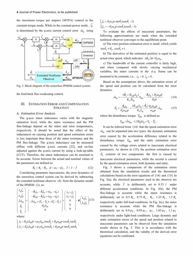
Fig. 2 shows the block diagram of the sensorless IPMSM control system based on the extended nonlinear observer, which consists of a speed PI (proportional-integral) regulator and two current PI regulators. The rotor speed and position are obtained through the extended nonlinear observer except for the startup period, where an open-loop sensorless starting
method is employed instead. The q-axis current reference *qi
is generated from the speed tracking error, and the d-axis
current reference *di is determined by *
qi , while employing
4 Journal of Power Electronics, to be published
the maximum torque per ampere (MTPA) control in the
constant-torque mode. While in the constant-power mode, *di
is determined by the q-axis current control error qi using
Fig. 2. Block diagram of the sensorless IPMSM control system.
the feed-back flux-weakening control.
III. ESTIMATION ERROR AND COMPENSATION STRATEGY
A. Estimation Error Analysis
The q-axis stator inductance varies with the magnetic saturation level, while the stator resistance and the PM flux-linkage depend on the stator and rotor temperatures, respectively. It should be noted that the effect of the inductances on causing position and speed estimation errors is less important than those of the stator resistance and the PM flux-linkage. The q-axis inductance can be measured offline with different q-axis currents [22], and on-line adjusted against the q-axis current by using a look-up-table (LUT). Therefore, the stator inductances can be assumed to be accurate. Errors between the actual and nominal values of the parameters are defined as:
s s s f fˆ ˆˆ, , R R R J J J (12)
Considering parameter inaccuracies, the error dynamics of the sensorless control system can be derived by subtracting the extended nonlinear observer (4) from the dynamic model of the IPMSM (3), as:
s s 1 1
2 2s s
m m e L e L
n me
L
ˆ ( )
ˆ ( )
ˆ 0ˆ( ) ( )0
00
q
q
L i R i R i u u
L i R i R i u uL i
J J T T T T L iP
T
K
(13)
where:
1 n m f m e n m e e
2 n m f m e n m e e
ˆ ˆˆ( )sin cos sin
ˆ ˆˆ( )cos sin sin
P P
P P
;
1 n m e e
2 n m e e
ˆsin (cos 1)
ˆcos (cos 1)
P
P
.
To evaluate the effects of inaccurate parameters, the following approximations are made when the extended nonlinear observer converges to the equilibrium point.
a) The rotor position estimation error is small, which yields
e e esin , cos 1 .
b) The derivative of the estimated position is equal to the
actual rotor speed, which indicates e n mˆ =d dt P .
c) The bandwidth of the current controller is fairly high, and when compared with slowly varying mechanical variables, the stator currents in the -d q frame can be
assumed to be constant, i.e., 0, 0d qi i .
Based on the assumptions above, the estimation errors of the speed and position can be calculated from the error dynamics.
s s n mm dis
nz
ˆ( )ˆ ˆ
q q
q
R K L R i PT
PK JL
(14)
ss n me m
n m z m
ˆ( ) ˆ ˆqd
q
K L RR i P
P K L
(15)
where the disturbance torque disT is defined as:
dis m n L L= 1.5 qT J P i T T .
It can be inferred from (14) that the speed estimation error
m can be separated into two types: the dynamic estimation
error caused by the acceleration difference related to the disturbance torque disT and the static estimation error
caused by the voltage errors related to inaccurate electrical parameters. As shown in (15), the position estimation error
e consists of two components: the first is caused by
inaccurate electrical parameters, while the second is caused by the speed estimation errors, both dynamic and static.
Fig. 3 shows a comparison of the estimation errors obtained from the simulation results and the theoretical calculations based on the error equations of (14) and (15). In Fig. 3(a), the electrical parameters used in the observer are
accurate, while J is deliberately set to 0.33 J under
different acceleration conditions. In Fig. 3(b), the PM flux-linkage is accurate while the stator resistance is deliberately set to 0.5 sR , 0.75 sR , sR , 1.25 sR , 1.5 sR
respectively under full-load conditions. In Fig. 3(c), the stator resistance is accurate while the PM flux-linkage is deliberately set to 0.9 f , 0.95 f , f , 1.05 f , 1.1 f
respectively under light-load conditions. Large dynamic and static estimation errors of the speed and position related to inaccurate parameters can be observed from the simulation results shown in Fig. 3. This is in accordance with the theoretical calculation, and the validity of the derived error equations can be confirmed.

Journal of Power Electronics, to be published 5
B. On-line Rotational Inertial Adjustment
As discussed in the previous section, dynamic estimation errors of the speed and position will arise during the acceleration and deceleration periods if the system
(a)
(b)
(c)
Fig. 3. Comparison of estimation errors obtained from simulation results and theoretical calculation considering the parameter inaccuracies: (a) the rotational inertia is inaccurate; (b) the stator resistance is inaccurate; (c) the PM flux-linkage is inaccurate.
rotational inertia and torque constant are inaccurate. To suppress the dynamic estimation errors, the rotational inertia must be on-line adjusted. The speed estimation error dynamics can be extracted from (13), and rewritten as:
m m e L e L z dˆ ˆ ˆ( ) ( )J J T T T T JK (16)
where the symbolic speed error d is defined as:
d e en
ˆ ˆ( sin cos )ˆ
qLi i
P
(17)
d reflects the speed dynamic estimation error caused by
the acceleration difference between m and m . To adjust
the rotational inertia by employing the gradient descent algorithm, the following objective function is defined.
2z d
1(
2ˆ )JF K (18)
As clearly shown, the objective function reaches its minimum only when d is zero. The gradient of F with
respect to J takes the form of:
dzJ d
ˆ( )ˆ zFF JK
J
K
J
J
(19)
According to (16), the partial derivative of z dJK with
respect to J is calculated as:
z dm
ˆ( )
J
JK
(20)
Substituting (20) into (19) yields:
z mJ dJKF (21)
According to the gradient descent algorithm, the rotational inertia should be adjusted towards the negative gradient of the objective function F , which leads to:

6 Journal of Power Electronics, to be published
J
z d
J
J mˆ ˆLPF )
ˆ
(ˆ
J J F K dt
J K K J dt
(22)
where J is the rotational inertia after adjustment, and
JK is the gain for the system rotational inertia
adjustment. In this application, JK is set to 0.2.
By considering the positive definite F as a Lyapunov function candidate, its derivative can be derived as:
2
J J J J J( ) ( ) 0
F dJF
J dtd
F F K dt K Fdt
(23)
This implies that the gradient descent based inertia estimator is stable. Given that m is unknown in practical
sensorless control systems, m is used instead to adjust the
rotational inertia, and a LPF (low pass filter) is supplemented
to eliminate the noise in m , with the cut-off frequency set
to 100 Hz. Fig. 4 shows the schematic diagram of the speed estimator with online rotational inertia adjustment.
Fig. 4. Schematic diagram of the rotor speed estimator.
As depicted in Fig. 4, the inputs of the speed estimator are
d , eT , LT , and J , with m as its output. Although the
inaccuracy of the PM flux-linkage causes the wrong
convergence of LT and J , the dynamic estimation error of
the speed corresponding to the first component of (14) is still effectively suppressed because J is adjusted to minimize
the objective function F .
C. Equivalent Flux Error Compensation
With the dynamic estimation errors of the speed and position already suppressed by on-line adjusting of the rotational inertia, the static estimation errors caused by inaccurate electrical parameters, still need to be eliminated.
In this study, the equivalent flux error equ is defined to
represent the effects of sR and .
s n mequ
n m
qR i P
P
(24)
By substituting the expression of equ into (14), the
static speed estimation error can be rewritten as:
equm mˆ
(25)
Considering that s dR i , in the first component of (15), is in
inverse proportion to the back-EMF, its effect is very small in the medium to high speed range and can be safely neglected.
Thus, e mainly comes from the speed estimation error.
Applying (25) into (15) and neglecting the first component of the position estimation error yields:
s n m eque
z
ˆ ˆ( )q
q
K L R P
K L
(26)
As indicated in (25) and (26), the static estimation errors of the speed and position are both proportional to the equivalent flux error. They can be eliminated by compensating equ in
the extended nonlinear observer. The position estimation error dynamics can be extracted
from (13) and rewritten as:
ze n m
n me eˆ ˆˆ ˆcos sinqK L
PP
i i
(27)
By substituting (25) into (27), the relationship between the equivalent flux error and the current estimation error under steady-state conditions can be derived as:
zequ 2 2
n me eˆ ˆˆ ˆcos sinq i i
K L
P
(28)
As clearly shown in (28), by considering the rotor speed to be constant for a very short time, the equivalent flux error is proportional to the current estimation error of the d-axis, and
can be compensated by forcing e eˆ ˆ( cos sin )i i to be
zero. Thus, an adaptive observer for the equivalent flux error estimation can be designed as:
eλ z
equ 2 2n m
eˆ ˆcˆ s
ˆos inq i i dt
K K L
P
(29)
where λK is the gain for the equivalent flux error
estimation. Recalling the definition of the equivalent flux error, the
stator resistance error and the PM flux error are the dominant components in the low and high speed regions, respectively. Although a large λK is beneficial in suppressing the
transient estimation errors caused by step-changes of qi , a
small λK is preferred in maintaining stable and low-noise
estimations. In this application, λK is set to 1.
To suppress the estimation errors of the speed and position caused by inaccurate electrical parameters, the estimated equivalent flux error is compensated in the proposed extended nonlinear observer. The resultant extended nonlinear observer with rotational inertia adjustment and equivalent flux error compensation is expressed as:

Journal of Power Electronics, to be published 7
n m equ es
n m equ es αm
β
e e L
n mL
ˆˆ ˆ ˆ ˆ( )sinˆˆ
ˆ ˆˆ ˆ ˆ ˆ( )cosˆ
ˆ
ˆ ˆ( )
ˆˆ0
q q q
q q q
PR uii L L L
i P uR iiL L L i
T T J
PT
K
(30)
IV. EXPERIMENTS AND ANALYSIS
The performance of the proposed sensorless control system is investigated on a testing platform based on a fixed-point DSP—TMS320F28234, as shown in Fig. 5 and Fig. 6.
The sampling frequency and the PWM frequency are both set to 10 kHz. The DC bus voltage is measured, and the
reference voltage *u is fed to the extended nonlinear
observer instead of the actual input voltage of the IPMSM. In addition, the dead time and the digital PWM delay are also compensated. A 2500-line incremental encoder is installed to measure the actual rotor position of the IPMSM. However,
N S N S
abi
dcU
Fig. 5. Testing platform setup.
Fig. 6. Photograph of the testing platform.
TABLE I
SPECIFICATIONS OF IPMSM IN EXPERIMENTAL TESTING
Parameter Value
Rated Power 1.0 (kW)
Rated Torque 4.8 (N·m)
Rated Current (peak) 4.0 (A)
PM flux-linkage 0.2 (Wb)
Stator Resistance 1.5 (Ω)
d-axis Inductance (id=0) 13.0 (mH)
q-axis Inductance (iq=0) 17.0 (mH)
Pole Pairs 4
Rated Speed 2000 (rpm)
System Rotational Inertia 3.0 (g·m2)
this is only done for reference purposes. The load torque imposed on the IPMSM is generated by a permanent magnet synchronous generator (PMSG) with a power resistor as its load. The IPMSM used in the experimental investigation has a skewed stator and an asymmetric air gap to optimize the sinusoidally distributed air-gap flux. Thus, the flux harmonics are negligible and the ideal motor model can be used. The specifications of the IPMSM are given in Table I. Fig. 7 shows the measured q-axis inductance of the prototype IPMSM under different q-axis currents.
Fig. 8 shows the speed step response of the sensorless IPMSM control system based on an extended nonlinear observer. The rotor speed steps from 100 rpm to –100 rpm and then back within 50 ms under light-load conditions. The experimental results demonstrate the stable operation of the sensorless control system through zero speed. The estimated speed tracks the actual speed smoothly except for the zero speed points.
Fig. 7. Measured q-axis inductance of the prototype IPMSM.

8 Journal of Power Electronics, to be published
Fig. 8. Experimental results of speed step response under light-load condition in the low speed region.
The maximum position estimation error during the transient periods is less than 30 , whereas the average position estimation error under the steady-state condition converges to zero despite the ripples.
Fig. 9 shows the dynamic performance of the sensorless control system against step load disturbances under low speed operation. The speed reference is fixed to 50 rpm (2.5% rated speed), and a 4 N·m (80% rated load) step load is applied and removed at 1.3 s and 4.8 s, respectively. Stable and good dynamic performance can be observed in the experimental results. Note that the load torque imposed on the IPMSM is proportional to the actual speed, and the estimated load torque tracks its actual value well. The speed and position estimation errors are well damped and rapidly converge to
zero, with the transient position estimation error below 20. Fig. 10 shows sensorless control results with and without
the rotational inertia adjustment in the extended nonlinear observer. The IPMSM steps from 500 rpm to 1000 rpm and back under light-load conditions. The electrical parameters
used in the observer a re accura te , whi le J i s
Fig. 9. Experimental results of dynamic performance against step load disturbance at 50 rpm.
Fig. 10. Experimental results with and without rotational inertia adjustment when inaccurate system rotational inertia is adopted.
deliberately set to 0.33 J . As shown in Fig. 10, large
dynamic estimation errors of the speed and position can be observed during the acceleration and deceleration periods. After the rotational inertia adjustment strategy is activated, the estimated rotational inertia J gradually converges to its
actual value, and the dynamic estimation errors are effectively suppressed. Additionally, the experimental results also indicate that a large JK results in a fast convergence
rate of J . However, it may cause remarkable estimation
overshoots as depicted in the estimation errors of the speed and position.
Fig. 11 shows the sensorless control results both with and without the equivalent flux error compensation against electrical parameter uncertainties accounting for the
(a)

Journal of Power Electronics, to be published 9
(b)
Fig. 11. Experimental results with and without the equivalent flux error compensation: (a) the stator resistance is inaccurate; (b) the PM flux-linkage is inaccurate.
temperature-rise and magnetic saturation effects. To simulate practical conditions, in Fig. 11(a), the PM flux-linkage is accurate and the stator resistance is deliberately set to 0.5 sR
with a full-load. Meanwhile, in Fig. 11(b), the stator resistance is accurate and the PM flux-linkage is deliberately set to 1.1 f with a light-load. Large static estimation errors
of the speed and position can be observed from these results, as shown on the left side of the dashed line in Fig. 11(a) and (b). After the equivalent flux error is compensated in the observer, the estimated speed and position gradually converge to their actual values in both cases, and the average static estimation errors tend to be zero. Although a large λK
is beneficial for fast convergence, the ripple content of the

10 Journal of Power Electronics, to be published
(a) (b)
(c) (d)
Fig. 12. Speed tracking performance with and without rotational inertia adjustment and equivalent flux error compensation, wheninaccurate system rotational inertia, stator resistance, and PM flux-linkage are adopted in the observer: (a) without rotational inertia adjustment and equivalent flux error compensation; (b) only with rotational inertia adjustment; (c) only with equivalent flux error compensation; (d) with rotational inertia adjustment and equivalent flux error compensation.

Journal of Power Electronics, to be published 11
(a)
(b)
Fig. 13. Steady-state performance under full-load condition with the q-axis inductance 20% larger than its actual value: (a) without the equivalent flux error compensation; (b) with the equivalent flux error compensation.
estimated equivalent flux error is relatively high, especially in the low speed region. In addition, significant oscillations can be found in the estimated speed and position.
Fig. 12 shows the speed tracking performance both with and without the rotational inertia adjustment and equivalent flux error compensation when inaccurate values for the system rotational inertia, stator resistance, and PM flux-linkage are adopted in the observer. The IPMSM is controlled to accelerate from 500 rpm to 1500 rpm and back within 0.1 s. The load torque imposed on the IPMSM is
approximately proportional to the actual speed. J is
deliberately set to 0.33 J , while sR and f are
deliberately set to 0.5 sR and 0.9 f to simulate the worst
case. In Fig. 12(a), large dynamic and static estimation errors of
the speed and position can be observed in both the transient and steady-state periods owing to inaccurate values of system rotational inertia and electrical parameters. In Fig. 12(b), only the rotational inertia adjustment strategy is activated, and the dynamic estimation errors are effectively suppressed, as
shown in parts ①–④. However, the static estimation errors
still need to be eliminated. In Fig. 12(c), only the equivalent flux error is compensated in the extended nonlinear observer, and the static estimation errors are effectively suppressed. However, dynamic estimation errors still exist during the acceleration and deceleration periods. Moreover, as depicted
in parts ② and ④, the performance of the equivalent flux
error compensation strategy deteriorates because of the speed estimation error during transient periods. In Fig. 12(d), the rotational inertia adjustment and the equivalent flux error compensation strategy are implemented in the extended nonlinear observer, and both the dynamic and static estimation errors are effectively suppressed.
Fig. 13 shows the steady-state performance of the sensorless control system under the full-load condition when the q-axis inductance is deliberately set 20% larger than its actual value. Accurate values for the system rotational inertia, stator resistance, and PM flux-linkage are adopted in the extended nonlinear observer. In Fig. 13(a), the equivalent flux error compensation strategy is disabled and considerable estimation errors of the speed and position can be observed. They are caused by the q-axis inductance error. In Fig. 13(b), the equivalent flux error compensation strategy is activated and the speed estimation error is effectively suppressed. However, a small position estimation error still exists. The experimental results indicate that exact inductance parameters are required for accurate position estimation and high efficiency sensorless control.
V. CONCLUSIONS
This paper proposed a sensorless control scheme for IPMSMs based on a full-order extended nonlinear observer with rotational inertia adjustment and equivalent flux error compensation. By taking parameter inaccuracies into account, explicit estimation errors of the speed and position have been derived, which can be separated into dynamic and static estimation errors. Furthermore, rotational inertia adjustment and equivalent flux error compensation approaches are proposed to improve the observer performance against parameter uncertainties, and the dynamic and static estimation errors of the speed and position have been effectively suppressed. Both experimental and analytical studies demonstrated that the proposed sensorless control strategy for IPMSM, not only has high performance on the estimation of the speed and position in both transient and steady-state periods, but also shows high robustness to parameter uncertainties over wide speed range.
ACKNOWLEDGMENT
This work was supported by the National Basic Research

12 Journal of Power Electronics, to be published
Program (973 Program) (2013CB035604), the Technology Application Research Program for Public Welfare of Zhejiang Province (2015C31125), and the Natural Science Foundation of Zhejiang Province (LY14E070004).
REFERENCES
[1] G. Pellegrino, P. Guglielmi, and A. Vagati, "Design tradeoffs between constant power speed range, uncontrolled generator operation, and rated current of IPM motor drives," IEEE Trans. Ind. Appl., Vol. 47, No. 5, pp. 1995-2003, Sep./Oct. 2011.
[2] D. Yin, S. Oh, and Y. Hori. "A Novel Traction Control for EV Based on Maximum Transmissible Torque Estimation," IEEE Trans. Ind. Electron., Vol. 56, No. 6, pp. 2086-2094, Jun. 2009.
[3] S. Kim, J. Ha, and S. Sul, "PWM switching frequency signal injection sensorless method in IPMSM," IEEE Trans. Ind. Appl., Vol. 48 No. 5, pp. 1576-1587, Sep./Oct. 2012.
[4] KG. Lee, JS. Lee, and KB. Lee, "Wide-range sensorless control for SPMSM using an improved full-order flux observer," Journal of Power Electronics, Vol. 15, No. 3, pp. 721-729, May 2015.
[5] Y. Inoue, Y. Kawaguchi, S. Morimoto, and M. Sanada, "Performance improvement of sensorless IPMSM drives in a low-speed region using online parameter identification," IEEE Trans. Ind. Appl., Vol. 47, No. 2, pp. 798-804, Mar./Apr. 2011.
[6] D. Paulus, J. Stumper, and R. Kennel, "Sensorless control of synchronous machines based on direct speed and position estimation in polar stator-current coordinates," IEEE Trans. Power Electron., Vol. 28 No. 5, pp. 2503-2513, May 2012.
[7] P. Kshirsagar, R. Burgos, J. Jang, A. Lidozzi, F. Wang, D. Boroyevich, and S. Sul, "Implementation and sensorless vector-control design and tuning strategy for SMPM machines in fan-type applications,". IEEE Trans. Ind. Appl., Vol. 48, No. 6, pp. 2402-2413, Nov./Dec. 2012.
[8] B. Nahid-Mobarakeh, F. Meibody-Tabar, and F. Sargos, "Back EMF estimation-based sensorless control of PMSM: robustness with respect to measurement errors and inverter irregularities," IEEE Trans. Ind. Appl., Vol. 43, No. 2 pp. 485-494, Mar./Apr. 2007.
[9] J. Dominguez, A. Navarrete, M. Meza, A. Loukianov, and J. Canedo, "Digital sliding-mode sensorless control for surface-mounted PMSM," IEEE Trans. Ind. Informat., Vol. 10, No. 1, pp. 137-151, Feb. 2014.
[10] T. Bernardes, V. Montagner, H. Grundling, and H. Pinheiro, "Discrete-time sliding mode observer for sensorless vector control of permanent magnet synchronous machine," IEEE Trans. Ind. Electron., Vol. 61, No. 4, pp. 1679-1691, Apr. 2014.
[11] G. Zhang, G. Wang, D. Xu, and N. Zhao, "ADALINE-network-based PLL for position sensorless interior permanent magnet synchronous motor drives." IEEE Trans. Ind. Electron., Vol. 31, No. 2, pp. 1450-1460, Feb. 2016.
[12] Y. Fan, L. Zhang, M. Cheng, and K. Chau, "Sensorless SVPWM-FADTC of a new flux-modulated permanent-magnet wheel motor based on a wide-speed sliding mode observer," IEEE Trans. Ind. Electron., Vol. 62, No. 5, pp. 3143-3151, May 2015.
[13] L. Idkhajine, E. Monmasson, and A. Maalouf, "Fully FPGA-based sensorless control for synchronous AC drive using an extended Kalman filter," IEEE Trans. Ind. Electron., Vol. 59, No. 10, pp. 3908-3918, Oct. 2012.
[14] S. Bolognani, L. Tubiana, and M. Zigliotto, "EKF-based sensorless IPM synchronous motor drive for flux-weakening applications," IEEE Trans. Ind. Appl., Vol. 39, No. 3 pp. 768-775, May/Jun. 2003.
[15] Y. Shi, K. Sun, L. Huang, and Y. Li, "Online identification of permanent magnet flux based on extended Kalman filter for IPMSM drive with position sensorless control," IEEE Trans. Ind. Electron., Vol. 59, No.11, pp. 4169-4178, Nov. 2012.
[16] M. Rashed, P. F. A. MacConnell, A. F. Stronach, and P. Acarnley, "Sensorless indirect-rotor-field-orientation speed control of a permanent-magnet synchronous motor with stator-resistance estimation," IEEE Trans. Ind. Electron., Vol. 54, No. 3, pp. 1664-1675, Jun. 2007.
[17] M. Hamida, J. Leon, A. Glumineau, and R. Boisliveau, "An adaptive interconnected observer for sensorless control of PM synchronous motors with online parameter identification." IEEE Trans. Ind. Electron., Vol. 60, No. 2, pp. 739-748, Feb. 2013.
[18] G. Zhu, A. Kaddouri, L. A. Dessaint, and O. Akhrif, "A nonlinear state observer for the sensorless control of a permanent-magnet AC machine," IEEE Trans. Ind. Electron., Vol. 48, No. 6, pp. 1098-1108, Dec. 2001.
[19] J. A. Solsona, M. I. Valla, and C. Muravchik, "Nonlinear control of a permanent magnet synchronous motor with disturbance torque estimation," IEEE Trans. Energy Convers., Vol. 15, No. 2, pp. 163-168, Jun. 2000.
[20] G. Bisheimer, M. O. Sonnaillon, C. H. De Angelo, J. A. Solsona, and G. O. Garcia, "Full speed range permanent magnet synchronous motor control without mechanical sensors," IET Electr. Power Appl., Vol. 4, No. 1, pp. 35-44, 2010.
[21] I. Boldea, M. C. Paicu, and G. D. Andreescu, "Active flux concept for motion-sensorless unified AC drives," IEEE Trans. Power Electron., Vol. 23, No. 5, pp. 2612-2618, Sep. 2008.
[22] S. Morimoto, M. Sanada, and Y. Takeda, "Effects and compensation of magnetic saturation in flux-weakening controlled permanent magnet synchronous motor drives," IEEE Trans. Ind. Appl., Vol. 30, No. 6, pp. 1632-1637, Nov./Dec. 1994.
Yongle Mao was born in China, in 1986. He received his B.S. and M.S. degrees in Electrical Engineering from the Harbin Institute of Technology (HIT), Harbin, China, in 2009 and 2011, respectively. He is presently working towards his Ph.D. degree in the College of Electrical Engineering, Zhejiang University, Hangzhou, China. His
current research interests include sensorless control and parameter identification in AC machines.
Jiaqiang Yang was born in China, in 1970. He received his Ph.D. degree in Electrical Engineering from Zhejiang University, Hangzhou, China, in 2004. He has been an Associate Professor in the College of Electrical Engineering, Zhejiang University, Hangzhou, China, since 2006. He was a

Journal of Power Electronics, to be published 13
research fellow at the National University of Singapore, Singapore, from March 2011 to April 2012. His current research interests include power electronics, electric machine drives, and control strategies.
Dejun Yin was born in China, in 1976. He received his B.S. and M.S. degrees in Electrical Engineering from the Harbin Institute of Technology (HIT), Harbin, China, in 1999 and 2001, respectively. He received another M.S. degree in Electronics Engineering from the Chiba Institute of Technology, Narashino, Japan, in 2002. He
received his Ph.D. degree in Electrical Engineering from the University of Tokyo, Tokyo, Japan, in 2009. He is presently working as a Professor in the Nanjing University of Science and Technology, Nanjing, China. His current research interests include vehicle control and drive/brake systems for next generation electric vehicles.
Yangsheng Chen was born in China, in 1969. He received his B.S. and M.S. degrees in Electrical Engineering from Zhejiang University, Hangzhou, China, in 1991 and 1994, respectively; and his Ph.D. degree in Department of Electric and Electrical Engineering from the University of Sheffield, Sheffield, England, UK, in 1999. He was a
Principal Engineer in CT and TRW, where he lead many significant projects, including high power density motors for industrial robots, aero electrical drive systems for flight control, the development of servo motors for the ABS/EPS/ABC systems in automobiles, and research on ECUs and sensors. He has been a Professor in the College of Electrical Engineering, Zhejiang University, Hangzhou, China, since 2005. His current research interests include permanent magnet synchronous control, the application of power electronics, motor designs for automobiles and related control systems, motor electromagnetism theory, and research on motor vibrations and noise.