senior design report table of contents
TRANSCRIPT

“Sub-Automatic”
EML 4905 Senior Design Project
A B.S. THESIS
PREPARED IN PARTIAL FULFILLMENT OF THE
REQUIREMENT FOR THE DEGREE OF
BACHELOR OF SCIENCE
IN
MECHANICAL ENGINEERING
“SUB-AUTOMATIC”
Final Report
Carlos Bonilla
Omar Tavarez
Daniel Pijeira
Advisor: Dr. Benjamin Boesl
April 11, 2014
This B.S. thesis is written in partial fulfillment of the requirements in EML 4551.
The contents represent the opinion of the authors and not the Department of
Mechanical and Materials Engineering.
P a g e | i
“Sub-Automatic”
Ethics Statement and Signatures
The work submitted in this B.S. thesis is solely prepared by a team consisting of Carlos Bonilla, Omar
Tavarez, and Daniel Pijeira and it is original. Excerpts from others’ work have been clearly identified,
their work acknowledged within the text and listed in the list of references. All of the engineering
drawings, computer programs, formulations, design work, prototype development and testing reported in
this document are also original and prepared by the same team of students.
Carlos Bonilla
Team Member
Omar Tavarez
Team Member
Daniel Pijeira
Team Member
Dr. Benjamin Boesl
Faculty Advisor

P a g e | ii
“Sub-Automatic”
Table of Contents
1. Introduction ...................................................................................................................................................... 1
2. Problem Statement ......................................................................................................................................... 2
3. Motivation ......................................................................................................................................................... 2
4. Literature Survey ............................................................................................................................................ 3
4.1 Machine Size Restrictions .............................................................................................................................................................................................. 3
4.2 Heat Sealing............................................................................................................................................................................................................................ 3
4.2.1 Constant Heat Sealing ........................................................................................................................... 3
4.2.2 Impulse Heat Sealing ............................................................................................................................. 4
4.2.3 Radio Frequency Sealing ...................................................................................................................... 4
4.2.3.1 Buffers .................................................................................................................................................................................................................................. 5
4.3 Vacuum Sealing .................................................................................................................................................................................................................... 5
4.3.1 External Sealer ........................................................................................................................................ 6
4.3.2 Vacuum Chamber Sealer ...................................................................................................................... 7
4.4 Plastics....................................................................................................................................................................................................................................... 8
4.4.1 Poly/Nylon COEX ................................................................................................................................. 8
4.5 Mechanism Selection ......................................................................................................................................................................................................... 8
4.5.1 Pneumatic ................................................................................................................................................. 9
4.5.2 Hydraulic .................................................................................................................................................. 9
4.5.3 Pure Mechanical ..................................................................................................................................... 9
4.5.4 Electro-Mechanical ................................................................................................................................ 9
5. Project Objectives .......................................................................................................................................... 10
6. Proposed Design ..............................................................................................................................................11
6.1 Process Flow Chart .......................................................................................................................................................................................................... 11
6.2 First Draft ............................................................................................................................................................................................................................. 12
6.3 Alternative Designs ......................................................................................................................................................................................................... 13
6.3.1 Wax Paper Folding .................................................................................................................................................................................................... 13
6.3.2 Plastic and Heat-Sealing Wrapper .....................................................................................................15
6.4 First Design Revision ...................................................................................................................................................................................................... 17
6.4.1 Second Design iteration: ......................................................................................................................................................................................... 19
6.4.2 Third Design Iteration: .......................................................................................................................................................................................... 20
6.4.3 Forth Design Iteration: .......................................................................................................................................................................................... 20
6.4.4 Fifth Design Iteration: ............................................................................................................................................................................................. 21
6.4.5 Sixth Design Iteration: ............................................................................................................................................................................................ 21
6.4.6 Seventh Design Iteration: ...................................................................................................................................................................................... 22
7. Project Management .................................................................................................................................... 23
7.1 Overview ................................................................................................................................................................................................................................ 23
7.2 Gantt Chart ......................................................................................................................................................................................................................... 23
7.3 Breakdown of Responsibilities ................................................................................................................................................................................. 24

P a g e | iii
“Sub-Automatic”
8. Miscelaneous Components ..................................................................................................................... 24
8.1 Shaft & Fasteners ............................................................................................................................................................................................................ 24
8.2 Material ................................................................................................................................................................................................................................. 27
9. Analytical Analysis and Structural Design......................................................................................... 30
9.1 Motor Specification ........................................................................................................................................................................................................ 30
9.2 Motor Circuit Design .................................................................................................................................................................................................... 37
9.3 Bearing Analysis ............................................................................................................................................................................................................... 39
9.4 Failure Mode & Effects Analysis (FMEA) ...................................................................................................................................................... 42
9.5 Structural Simulation ................................................................................................................................................................................................... 43
10. Cost Analysis............................................................................................................................................... 51
10.1 Component Estimates ..............................................................................................................................................................................................51
10.2 Funding and Sponsors ............................................................................................................................................................................................. 53
10.3 Man-Hour ...................................................................................................................................................................................................................... 53
11. Prototype System ...................................................................................................................................... 54
12. Testing ................................................................................................................................................................ 56
12.1 Folding Test ......................................................................................................................................................................................................................... 56
12.2 Motor Test ............................................................................................................................................................................................................................ 57
13. Conclusion .................................................................................................................................................. 58
14. Appendix A – FDA Regulations ............................................................................................................ 59
U.S. Department of Health and Human Services – Food and Drug Administration ................................................................................. 59
Multiuse 4-101.11 - Characteristics ................................................................................................................... 59
Multiuse 4-101.12 – Cast Iron Use Limitation ................................................................................................ 59
Multiuse 4-101.13 – Lead Use Limitation ........................................................................................................ 60
Multiuse 4-101.14 – Copper Use Limitation .................................................................................................... 60
Multiuse 4-101.15 – Galvanized Metal Use Limitation .................................................................................61
Multiuse 4-101.16 – Sponges Use Limitation ...................................................................................................61
Multiuse 4-101.17 – Wood Use Limitation .......................................................................................................61
Multiuse 4-101.18 – Nonstick Coatings Use Limitation ............................................................................... 62
Multiuse 4-101.19 – Nonfood-Contact Surfaces ............................................................................................. 62
Single-Service and Single-Use 4-102.11........................................................................................................... 62
Cleanability 4-202.11 Food-Contact Surfaces ................................................................................................. 63
Functionality 4-204.15 Bearings and Gear Boxes, Leakproof ..................................................................... 64
Appendix B – Quotes ............................................................................................................................................ 65
Appendix C – Time Log ....................................................................................................................................... 72
Appendix D – List of Tasks ................................................................................................................................. 73
Appendix E – 2D Drawings ................................................................................................................................. 74
Appendix F – Failure Mode & Effects Analysis (FMEA) ............................................................................. 81
16. References ......................................................................................................................................................... 82
P a g e | iv
“Sub-Automatic”
List of Figures Figure 1 - Constant Heat Sealer ................................................................................................................................................................................................................................... 3
Figure 2 - Impulse Heat Sealer ...................................................................................................................................................................................................................................... 4
Figure 3 – External Sealer ................................................................................................................................................................................................................................... 6
Figure 4 – External Vacuum Sealer ............................................................................................................................................................................................................. 7
Figure 5 – Internal Vacuum Sealer .............................................................................................................................................................................................................. 7
Figure 6 - Timeline for Fall and Spring ................................................................................................................................................................................................ 23
List of Tables Table 1: List of responsibilities for each team member 24
Table 2 - Stress Calculations based on rpm = 15.28 rpm (2:1 ratio) 36
Table 3 - Stress Calculations based on rpm = 15.28 (3:1 ratio) 37

P a g e | v
“Sub-Automatic”
Abstract
With the increase of fast food restaurants, particularly the sandwich style eateries, a
growing inefficiency in the preparation of the meal has become apparent. Our task is to design a
small, inexpensive, safe, efficient and practical machine that will significantly reduce the time it
takes to complete assembly of a sub. This type of approach has never been implemented in a
high output commercial setting, but with the FDA and ISO regulations.
By providing a machine to automate the folding process, our machine can free up
employees to focus on product preparation and increase revenue for the business. The cost of the
machine will be low enough when mass manufactured, making it appealing to business owners.
P a g e | 1
“Sub-Automatic”
1. Introduction
In today’s economy we are constantly finding ways to make processes faster and cheaper. As
engineers we can be approached with projects to do just that, whether they are analyzing and
optimizing data, machines, assembly lines etc. In our case, an investor, who is trying to optimize
a sandwich restaurant sub-assembly line, approached us.
The main issue was the amount of time employees devoting to wrapping, cutting and folding the
sub-sandwich when they could be assisting other customers with their food. By improving on the
wrapping step the amount of product made and the attention to the customers will increase.
The first sketch brought to our group was purely mechanical and it will still require an employee
to operate. As a group we are going to combine electro-mechanical concepts and a new design
for the machine so we would be able to take the tedious step of wrapping and folding the
product. Having done this, we are going to free the employee from taking time to wrap and fold
and instead they will be able to assist another customer and improve sells. In the process of
wrapping we will pack the product in a sealed bag to prolong freshness and flavor.

P a g e | 2
“Sub-Automatic”
2. Problem Statement
Design and build a sub folding machine that meets all governmental regulations and
requirements while being a safe, efficient, practical and cost effective solution.
3. Motivation
A good portion of machines that are fabricated in today’s society are generally created to
fulfill a need. This project is not an exception to this statement. One of the main purposes of
designing this system is to reduce a tedious, time consuming task that is nonetheless necessary in
the workplace today. In doing so, our hope is that this improvement will allow employees of
these various businesses to instead focus their attention to other tasks that could make them more
efficient. In addition to easing the process, we aim to utilize technology to expand the life of the
end product.
This project is multi-faceted in that it has business challenges in addition to the
engineering and governmental challenges presented. This added complexity is brought on by the
product’s marketability and interaction with the consumer public. Meaning, the ultimate design
and development of the solution must take into account aesthetics as well as ease-of-use, all the
while remaining compliant with governmental regulations. In completing this project, we are
also gaining valuable knowledge in how engineering problems are approached and how various
solutions are presented and ultimately marketed.

P a g e | 3
“Sub-Automatic”
4. Literature Survey
4.1 Machine Size Restrictions
The current space used for the wax paper at Subway is 16” x 16”, with this removed to make way for our
machine and with an extra space of 12” that we were able to determine was available, our machine had to
be confined to a length of 28” inches. The current length for our last iteration is 24” which is less than the
space available.
4.2 Heat Sealing
When sealing an object inside of two or more pieces of plastic, the method used to weld them
together is known as heat-sealing. This is achieved by pressing two sheets together using a punch press
machine that is equipped with a heating sealing die. This is accomplished by using a lower and upper
platen. Each platen normally consists of one or more bars, usually made of brass. Once the plastic sheet is
placed between the two platen, they are pressed together and the machine is turned on, causing the sheets
to fuse together. This fusion can occur from two sources: heat or radio
frequency energy.
4.2.1 Constant Heat Sealing
Constant heat sealing technique is the most straightforward and
commonly used method. The heat on the brass bars from the sealing die, in
conjunction with the pressure applied, will melt the plastics together. The
challenge found in this type of sealing is determining the amount of heat required to fuse the sheets of
plastic together without burning them. The disadvantages of this process are that its parts are constantly
hot and consume energy to maintain this temperature. In addition, the cooling process is not sped up in
any way, and is left to effects of natural convection.
Figure 1 - Constant Heat Sealer
P a g e | 4
“Sub-Automatic”
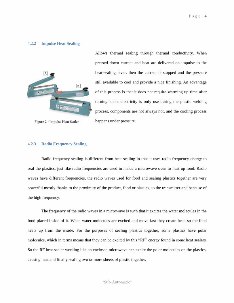
4.2.2 Impulse Heat Sealing
Allows thermal sealing through thermal conductivity. When
pressed down current and heat are delivered on impulse to the
heat-sealing lever, then the current is stopped and the pressure
still available to cool and provide a nice finishing. An advantage
of this process is that it does not require warming up time after
turning it on, electricity is only use during the plastic welding
process, components are not always hot, and the cooling process
happens under pressure.
4.2.3 Radio Frequency Sealing
Radio frequency sealing is different from heat sealing in that it uses radio frequency energy to
seal the plastics, just like radio frequencies are used in inside a microwave oven to heat up food. Radio
waves have different frequencies, the radio waves used for food and sealing plastics together are very
powerful mostly thanks to the proximity of the product, food or plastics, to the transmitter and because of
the high frequency.
The frequency of the radio waves in a microwave is such that it excites the water molecules in the
food placed inside of it. When water molecules are excited and move fast they create heat, so the food
heats up from the inside. For the purposes of sealing plastics together, some plastics have polar
molecules, which in terms means that they can be excited by this “RF” energy found in some heat sealers.
So the RF heat sealer working like an enclosed microwave can excite the polar molecules on the plastics,
causing heat and finally sealing two or more sheets of plastic together.
Figure 2 - Impulse Heat Sealer

P a g e | 5
“Sub-Automatic”
With RF energy sealing just like in microwaves the response is faster because it does not require
heating time, also the cooling down process is much faster. With a faster cooling process than regular
heating, the integrity of the seal is better, it is safer to handle, and the product turn over faster.
4.2.3.1 Buffers
Another factor to take into a count is the need of a buffer when using RF energy. The buffer you
should be used between the plastics and the lower platen. The purpose is to require the sealer to use more
RF energy to weld the plastics together. While the RF energy is melting the plastics its electrical field is
trying to complete a full circuit and the nearest place is the bottom of the sealing die, without a buffer the
thinnest part of the welded plastic will be the easiest way to complete a full circuit and the RF energy
would be flooded to the bottom platen and create a hole in your seal.
A buffer provides enough resistance to the RF energy and will keep it distributed through the seal
being put by the die. This way the seal will not be unevenly heated and the seal will be uniform. The
determination of what is too much power or too little is wider when the seal is being dealt evenly. Buffers
also help with sticking of the material and the releasing after the seal is done, the heat sealing die being
softer than the bottom plate usually made of steel, will use the buffer as landing place.
4.3 Vacuum Sealing
When food is exposed to the air, it ripens faster due to oxygen exposure than when food is
vacuumed sealed. Food is undesirable and/or uneatable as a result of the exposure to oxygen. This
exposure helps the growth of mold and bacteria. By removing the air from the bag we can effectively
impede some mold and some bacteria growth. The life of fresh foods packed inside a vacuum is elongated
and flavor and appeal conserved. This process is called vacuum sealing and is being investigated for our
design.

P a g e | 6
“Sub-Automatic”
This type of sealing refers to the process in which a product is introduced inside a plastic bag and
the air accumulated inside the bag is evacuated. There are different types of vacuum sealers, we would
research the different options available and determine which one could be used for our design. Some of
the machines being considered are explained as follows.
4.3.1 External Sealer
The sealing during an external sealing process describes when a vacuuming machine does the sealing and
vacuuming outside the actual machine. An example of this kind of machine is shown below in fig(3):
Figure 3 – External Sealer
This type of external vacuuming machine uses bags that have ridges, and it is mainly used for at
home vacuum sealing. The air is vacuumed out of the bag by the use of cavities; these cavities are present
where the machine, right at the bag’s open edges, is holding the plastic bag. Another type of external
sealing is used for commercial sealing, this machine uses a “snorkel” and smooth bags, as shown below in
fig (4).

P a g e | 7
“Sub-Automatic”
Figure 4 – External Vacuum Sealer
This external vacuuming machine evacuates the air from the smooth bag by means of a “snorkel”,
represented below as a probe inside the bag.
4.3.2 Vacuum Chamber Sealer
For this type of vacuuming smooth bags are used and the product is entirely inside the machine.
A pump inside the machine extracts all the air inside the chamber, and after that the open edges of the
plastic are heat sealed, closing in the bag and finishing the process. Some machines introduce inert gasses
like nitrogen after air evacuation and before sealing. This produces a seal that not tight like the one with
vacuuming alone, this is used for fragile products such as potato chips. Figure (5) shows a vacuum
chamber machine schematic:
Figure 5 – Internal Vacuum Sealer

P a g e | 8
“Sub-Automatic”
4.4 Plastics
Plastic wrapping can be made in different ways and depends on the type of machine used.
Individual bags can be used, these are usually better for in home use. Another way to use plastic wrapping
is to buy rolls of plastic and make your own pouches or bags. The latter one is more cost effective and
better for commercial use.
Plastic sheets are also different as far as materials and thickness. For the purpose of our project
we need only use FDA and USDA approved contact safe materials. TO determine if one ply or several
ply sheets could be used; we would need to take into consideration how well the plastics keep freshness,
the cost and their heat-sealing properties.
4.4.1 Poly/Nylon COEX
These types of bags for vacuuming are food contact safe and cost effective. They are a co-
extruded vacuum pouches meeting FDA and USDA guidelines for food products. It is made of a mixture
of polyethylene and nylon resins, and several layers allow it to be malleable and able to conform to
different product shapes.
This material also has a high impact resistance and an oxygen transfer rate that is low. It is in a
nutshell high in strength, clear, and flexible. It is resistant to oxygen transfer and vapor transmittance
while meeting FDA and USADA rules.
4.5 Mechanism Selection
For our machine we need to determine which medium to use to produce the mechanical motion that we
require to make the machine functional. To choose a way to produce this motion we investigated the
following mechanisms.

P a g e | 9
“Sub-Automatic”
4.5.1 Pneumatic
Pneumatics refers to the use of pressurized gas as the force to produce mechanical motion. By regulating
the pressure of the gases inside a chamber, like a cylinder, the system can drive a piston to produce
motion at the speed desired.
The use of compressed air is expensive, loud and not too practical. For our purposes we will discard this
system.
4.5.2 Hydraulic
Like the pneumatic system, the hydraulic system uses a pressurized medium to deliver force for
mechanical motion. In this system the medium used is hydraulic fluid; these fluids can be water or
mineral oil.
This system represents a problem for our design because these systems can leak the hydraulic fluid and
represent a health hazard.
4.5.3 Pure Mechanical
A mechanical system will deliver forces to cause the movement we need to operate our machine’s design
using power from a human operator and/or gravity.
As one of our main goals we want to limit the need of a human operator. The system could be mechanical
but it would have to draw its power from an electrical motor.
4.5.4 Electro-Mechanical
An electromechanical system is able to deliver the forces we need and it would be automated since the
power comes from electric motors. This would help us achieve one of our goals of freeing employees
from the wrapping process.

P a g e | 10
“Sub-Automatic”
5. Project Objectives
We have four main goals that we must meet in our final prototype. The paramount goal being
safety will be tackled by possibly automating some of this process, and our initial idea is to use some type
of conveyor system. Secondly, to make this final system efficient, we will look at incorporating two steps
into one simultaneously; folding the sub as it is being packaged. Lastly, we must design this system to be
practical and cost-effective. We tackle these two tasks by designing a system that is modular, expandable
and marketable. Moreover, we design the system to eliminate the tedious, yet necessary task of folding
and wrapping sandwiches. We have also decided to go one step further in our design, and look to
incorporate vacuum sealing technology to extend the lifespan of the sandwiches, adding value to the
product and marketability.

P a g e | 11
“Sub-Automatic”
6. Proposed Design
6.1 Process Flow Chart
The chart above explains the normal process from the moment a customer walks into the store, to the time
the customer receives the end product. In this process, the goal of our machine is to handle some of these
steps so the employee is able to help the next customer. In the flow chart above, the process would be
altered beginning at the first wrap, and would end in the final finished product.
The blue line path shows the current process followed by employees at a sub-shops, the red line shows
what would be the new process that employees would follow. The interaction time an employee would be
a part of in the completion of the sub making and is dramatically cut since the steps of wrapping, cutting
and bagging are eliminated from their routine. The green line process represents the steps the machine
would take over.

P a g e | 12
“Sub-Automatic”
6.2 First Draft
The initial design was brought forth to us by our investor. The preliminary idea is of a machine that will
achieve the ultimate goal of saving time by taking over the wrapping process of a sandwich in a
restaurant. The following sketch represents these ideas:
This machine would be purely mechanical and need to be operated by an employee. This employee would
need to use a crank or a foot pedal to allow the machine to fold and wrap the sandwich.
Pros:
Small design for ease of adaptation in an existing sub-shop line
Challenges:
Press bar and possible foot pedal represent high risk for the operator

P a g e | 13
“Sub-Automatic”
No automation
Added complexity in creating a functional design from scratch, rather than modifying an existing
one
Not easily disassembled for cleaning and sanitary reasons
The objective is to utilize existing technology and adapt it to a new design, while requiring the design of
the least amount of parts to accomplish this retrofit.
6.3 Alternative Designs
From the conducted research, it has been found that currently these types of machines are made for mass
production in factories and not intended for small scale application. One of the many challenges is
choosing a design that would be easiest to retrofit into a small scale application. The following represent
types of machines that can be utilized.
6.3.1 Wax Paper Folding
This design pushes the sandwich from a ‘ground’ level to a higher level while it is wrapped and folded in
this transition.
“ground”
level
Upper
level

P a g e | 14
“Sub-Automatic”
From the picture above, the wax paper is placed on top of the sandwich while the stainless steel cylinder
is oriented above it. The sandwich is then pushed through the opening, thus wrapping the paper around it
as shown by the following picture:
When the sandwich is pushed through the cylinder, the task then becomes to fold the loose ends that are
on the bottom of the sandwich. Also from the picture above, the use of a folding arm accomplishes this
task as the sandwich is pushed through. Once these tasks are accomplished, another arm is used to help
move the sandwich along the conveyor belt towards the packing section.
Stainless
Steel
cylinder
Paper wrap
Folding
Arms

P a g e | 15
“Sub-Automatic”
Pros:
Design already exists
Fully automated
Challenges:
Large design and multi-level movement is complicated
High risk if not fully enclosed
Expensive
6.3.2 Plastic and Heat-Sealing Wrapper
One that is currently available is the horizontal flow wrapper, which is used for vacuuming, wrapping and
sealing food. This technology currently exists on a mass production scale as well as a table top application
for the home
Pushing
arm

P a g e | 16
“Sub-Automatic”
.
In the picture above, the sandwich is placed on the beginning of the conveyor belt where a sheet of plastic
is oriented above it. It then undergoes a process where the air inside of the plastic is vacuumed out and
then it is hermetically sealed. This same process can be purchased for use in the home, as shown by the
following picture:
While this is a great alternative for personal use, it would take too much time operating the machine to be
efficient in a restaurant setting.
Pros:

P a g e | 17
“Sub-Automatic”
Vacuum sealing technology will increase the longevity and freshness of the product, in turn
increasing customer satisfaction and sales
A possible conveyor system would automate the wrapping and folding process, allowing the
employee to perform other tasks
Challenges:
Design the machine within a constrained amount of space
Keep design cost at a minimum
An agreement was made that a machine that could vacuum and seal the sandwich would be a great selling
point, since it would increase the freshness and hopefully increasing overall sales. It was then that another
decision was made to use existing table-top applications of this technology and retrofit it into a new
design.
The ultimate goal of designing this machine is to allow the employee to use their time elsewhere, rather
than wrapping and folding a sandwich.
6.4 First Design Revision

P a g e | 18
“Sub-Automatic”
The picture above represents the concept design, which acts as the starting point for the
prototype. The process incorporates all of the research and concept ideas that have been mentioned thus
far. The sandwich will be placed at the start of the conveyor system where it will be moved along through
the narrowing opening, folding the sandwich as it is pushed into a bag to be vacuum-sealed.

P a g e | 19
“Sub-Automatic”
6.4.1 Second Design iteration:
Our first iteration features a modular design. The different parts include: a conveyor belt, cutter,
and a folding tunnel.
Conveyor Belt: This feature is made up of rollers, bearings, railings, and belt. It is composed of
2 separate conveyors that can be disassembled to allow easy sanitation. The purpose of this part
is to take over the sub form the employee and carry it throughout the folding and wrapping
motions. The size of the railings will fit a regular restaurant dishwasher
Folding Tunnel: This feature will fold the sub while it is transported on the conveyor belt. It
will be attached to the railings with pins, to allow easy disassembling and cleaning. It will fit a
restaurant dishwasher
Cutter: The cutter will be optional; it will cut the sandwich in half before the wrapping happens.
Vacuum: After testing the vacuuming feature ruined the sandwich by squashing it, and it took a
long time to complete. Vacuuming of food is used for long term storing of foods and the purpose
of our packaging is meant to last for less than a day. After these discoveries we decided to go
with the heat-sealing alone.

P a g e | 20
“Sub-Automatic”
6.4.2 Third Design Iteration:
For this iteration we included the bag holder to be included in the design, instead of in a separate
attachable feature. This holder will simply hold the plastic sleeves in which the sub will be put
into. This part will also fit a dishwasher, the bags would be heat sealed to preserve the product.
6.4.3 Forth Design Iteration:
In this iteration the cutter was changed to a horizontal position, this cutter was meant to be
automated. After the cut the product would go into the bag holder.

P a g e | 21
“Sub-Automatic”
6.4.4 Fifth Design Iteration:
Moving forward with the design we decided to focus in the folding channel and conveyor belt,
these parts would automate the folding process. We also decided to leave the cutting to the
operator. This is why this new revision does not have an automated cutter added. In the future
one could be built and assembled easily through the use of screws to the cutting board.
6.4.5 Sixth Design Iteration:
This design changed in several ways. The first was the removal of vacuuming feature to a heat-
sealing alone one. Also the rails will extend from beginning to end of the machine instead of
them being separated into different parts.

P a g e | 22
“Sub-Automatic”
Railings: After reaching out to manufactures in the field, we decided to change our railing to one
that extends throughout the machine. This allows for more flexibility in the placing of the bag
holder and cutter; it is more cost effective while adding stability and less time for disassembling
of the machine. The new length of the railings will still be able to fit a dishwasher for sanitizing.
Bearings: For our bearing selection we found stainless steel, enclosed, FDA approved ones.
These bearings will facilitate the conveyor belt motion. By choosing enclosed bearings we
guarantee that the machine could keep operating even with food particles falling into them.
Motor: A DC motor is required to power the conveyor belt. We chose whose speed could be
adjusted. By doing this we can select an appropriate speed for the carrying of the sub through the
process.
6.4.6 Seventh Design Iteration:
In this design we added railings with multiple holes to optimize the location of the parts to find
the best position for the components. This also allowed us to position the motor in a way where
gears could be added to reduce the speed of it if needed. This new design was meant to allow
flexibility in the component positions since this machine is not in existence we had to be able to
try many different alternatives

P a g e | 23
“Sub-Automatic”
After using 3D printed parts for the prototyping, we finalized the location of the folding rails and
the motor. Also we were able to use the bearings and shafts we previously selected. A motor
cover was added to protect the user and the circuit needed to run the motor. Pins and screws
were also finalized; these hold the motor cover, bearings, folding channel and cutting board.
7. Project Management
7.1 Overview
The idea for this project was brought out by Mr. Norman Wartman. After meeting with him once
we learned that he expects us to select alternatives for the project, cost estimation, final designs
etc. For the fall semester we will have a 25% of the report ready in which we will have a
preferred design and be ready to start drafting and simulating on CAD. For the spring semester
starting on winter break we will construct and test and provide a final report including lessons
learned as requested by Mr. Wartman.
7.2 Gantt Chart
Figure 6 - Timeline for Fall and Spring

P a g e | 24
“Sub-Automatic”
7.3 Breakdown of Responsibilities
Table 1: List of responsibilities for each team member
8. Miscelaneous Components
8.1 Shaft & Fasteners
The design was made to fit type 316 Stainless Steel Socket Head Cap Screw.
10-32 Thread, 3/4" Length; these screws would be used to hold the motor cover and the front bearings in
place. The specifications are shown below:
Carlos
Current Facility Research
Danny
FDA Regulation
Patent Lookup Material Specification and Selection
Instruction Manual Production Data Analysis
Sealer Selection Motor Analysis
Omar
SolidWorks Design
All
Literature Survey
SolidWorks Simulation Conceptual Design
ISO 22000 Regulation Construction
ISO 9000 Facility Allocation Test Analysis

P a g e | 25
“Sub-Automatic”
To hold the rest of the bearings, non-marring flat point socket set screws Type 316 Stainless Steel, 10-32
Thread, 3/16" long, were used. These would not extend out of the railings allowing the channels and other
parts to be mounted on top of them. Their specifications are shown below:
A D-Profile Shaft Type 303 Stainless Steel, 1/4" OD, 48" length, was cut into 6 inch smaller shafts for the
conveyor belt. The specifications are shown below:

P a g e | 26
“Sub-Automatic”
Other parts used were the pins, (Quick-Release Pin Aluminum, 1/4" Diameter, 1.5" Usable Length), to
hold the channels and cutting board in place and we also needed. Their specifications are shown below:

P a g e | 27
“Sub-Automatic”
8.2 Material
There were many different types of resin available. The following guide was used to eliminate the
materials that were not food safe:
Mechanical properties
Resin generic name Some brand names Strength Impact
resistance
High temp.
strength
Polypropylene Maxxam, Profax Low High Low
High Density Polyethylene (HDPE) Dow HDPE,
Chevron HDPE Low High Low
Polystyrene Styron Medium-
Low Low Low
Acrylic Plexiglas, Acrylite Medium Low Low
Moldability Characteristics
Resin generic
name
Warp and
dimen-
sional
accuracy,
molded
Fills
small
features
Voids in
thick
sections
Sink in
thick
sections
Flash
High temp.
hard on
mold &
ejectors
Relati
ve
cost
Polypropylene Fair Excelle
nt Poor Poor Poor Good Low
High Density
Polyethylene
(HDPE)
Fair Excelle
nt Unknown Poor Poor Good Low
Polystyrene Good Good Unknown Fair Fair Good Low
Acrylic Good Fair Excellent Good Good Good Mediu
m

P a g e | 28
“Sub-Automatic”
We also eliminated materials that were too costly; after narrowing down to these materials, we used the
cost for one of the parts for comparison:
Resin Material Cost
Material Material Type Cost Half Moon at
25
Acetal Copolymer, Black (Celcon M90 CD3068) Resin Low 1989.50
Acetal Copolymer, Natural (Celcon M90 CF2001) Resin Low 1989.50
Acrylic (PMMA), Clear (Plexiglas V052-100) Resin Low 1989.25
HDPE, Natural (Marlex 9006 HID) Resin Low 1983.50
HDPE, Natural (Unipol DMDA 8007) Resin Low 1986.25
LDPE, Natural (Dow LDPE 722) Resin Low 1987.25
LLDPE, Cherry Red UN3788 (Dowlex 2517) Resin Low 1986.50
LLDPE, Natural (Dowlex 2517) Resin Low 1986.50
PET, Black 35% Glass Mica Low Warp (Rynite 935
BK505) Resin Low 1992.00
PP Homopolymer, Natural (Profax 6323) Resin Low 1984.75
PP Homopolymer, Natural (Profax 6523) Resin Low 1984.00
PP Homopolymer, Purple UN55094 (Profax 6523) Resin Low 1984.00
PP Random Copolymer, Natural (FHR PP P5M6K-048) Resin Low 1984.25
TPE, Black (Santoprene 111-35) Resin Low 1987.25
After eliminating the materials available for the parts that required CNC manufacturing, taking into
account which were not food safe and the ones that are too costly, we narrowed down to the following
materials and compared the cost for the same part as the resin:
CNC Material Cost
Material Type Cost Half Moon at
25
Aluminum - Gray (Aluminum 6061-T651)
Soft metal Low 1175.00
Aluminum - Gray (Aluminum 7075-T651) Soft metal Low 1225.00
Stainless Steel - Gray (Stainless Steel 316/316L) Hard metal Very
High 4700.00
HDPE - Natural (White) (High Density Polyethylene) Plastic Low 725.00
PMMA - Clear (Acrylic) Plastic Low 850.00
PP Homopolymer - Black (Polypropylene Homopoly) Plastic Low 950.00
PP Homopolymer - Natural (Polypropylene Homopoly) Plastic Low 950.00
PP Copolymer - Natural (Polypropylene Copoly) Plastic Low 925.00
PVC - Gray (PVC) Plastic Low 825.00
UHMW - Natural (UHMW) Plastic Low 775.00

P a g e | 29
“Sub-Automatic”
The material we decided to go with was 6061 aluminum for CNC machining. Aluminum is cheap and has
higher weight which would make the machine rigid and keep it in place. We chose 6061 aluminum over
7075 for cost, and 7075 is zinc based which could be detrimental to health if there is accidental
consumption. On the other hand 6061 is made partly of silicon, magnesium and iron, which would not be
detrimental if accidental ingestion, occurs.
For molding, Acrylic (PMMA), Clear (Plexiglas V052-100), Acetal Copolymer, Black (Celcon M90
CD3068), and Acetal Copolymer, Natural (Celcon M90 CF2001) were selected. Cost was not a factor
since the resin materials were about the same, but using the guide we showed above we took into account
what was the strength, impact resistance, the void in thick sections etc.

P a g e | 30
“Sub-Automatic”
9. Analytical Analysis and Structural Design
9.1 Motor Specification
To maintain simplicity of the machine, the decision was made to use a small DC gear motor to provide
the torque needed to move the conveyor belt. This motor would be mounted on the side of the aluminum
rails, perpendicular to the rollers of the conveyor belt. The use of bevel gears is necessary to allow the
transmission of power at a 90 degree angle.
In order to be able to specify a motor based on analysis, design specifications must be introduced. To
maintain the safety of the machine, it was decided to limit the pitch line velocity of the gear driving the
roller to 1 inch per second. In addition to limiting the velocity, a minimum torque of 7 lb·in will be
necessary to move the sandwich along the conveyor system and to be able to overcome the friction of the
sandwich passing through the narrowing channel. This torque was also selected to add a safety measure
so that in the motor is much less likely to stall during operation, causing possible permanent damage. The
following table summarizes the design specifications:
vt (pitch line velocity) 1 in/s
T (minimum torque) 7 lb·in
Design Factor (for stress analysis) 1.2
In addition to the design specifications from the table above, we will consider the use of a 2:1 and 3:1
gear ratio for the analysis. The following table summarizes the gear characteristics that will be used in the
calculations:

P a g e | 31
“Sub-Automatic”
2:1 Steel
Pinion 2:1 Steel Gear
3:1 Steel
Pinion 3:1 Steel Gear
Pd
(diametral pitch [teeth/in]) 16 16 16 16
N
[# of teeth] 20 40 20 60
F
(face width [in]) 0.312 0.312 0.312 0.312
dp
(pitch diameter [in]) 1.25 2.5 1.25 3.75
Pressure Angle
[°] 20 20 20 20
The following gear analysis will be conducted as per ANSI/AGMA 2003-B97 guidelines. According to
these guidelines, for bevel gears, the equations for contact stress and bending stress are as follows:
Contact Stress √
Contact Strength ( )
Bending Stress
Bending Strength
Since the process of specifying a motor to meet certain criteria is an iterative process, we will begin by
assuming the rpm and torque of a motor so calculations can be made. Once these calculations have been
made, we can compare the results of the assumed motor to the design specifications. From this point, we
are able to see what changes need to be made about the motor to satisfy the guidelines. Once the
guidelines are met, we compare the optimal findings of the motor to those that are readily available for

P a g e | 32
“Sub-Automatic”
purchase on the market. Further iterations may be necessary if a motor specification turns out to be a
special order, or should a different motor be found to satisfy cost requirements.
Since this process is an iterative one, the use of a spreadsheet will drastically reduce the calculation time.
Before proceeding, the following table summarizes the assumed initial performance of a certain DC gear
motor:
RPM 20
Torque (@ max rpm) 11.56 lb·in
Based on the performance of this motor, we can calculate the rpm and torque of the bevel gear using the
following relationship:
This relationship states that the power of a motor is equal to the product of torque and angular speed. To
further use this relationship, we further assume that the power loss from gear friction is negligible in this
case, allowing us to state that the input power is equivalent to the output power. Therefore:
This then leads to the relationship which allows us to calculate the output torque:
(
)
The following table summarizes the torque output for the 2:1 and 3:1 gear ratio:

P a g e | 33
“Sub-Automatic”
2:1 ratio 3:1 ratio
T [lb·in] 23.12 34.68
Based on the gear ratios, we can also calculate how the angular speed changes between each gear:
2:1 ratio 3:1 ratio
ω [rpm] 10 6.67
Now that the angular speed and torque are known for each gear, these will be the input factors for the
stress analysis that follows.
For the stress analysis, various terms in the stress equations need to be addressed before calculations can
be made. The following table summarizes all of the assumptions that were made when performing
calculations:
Qv Quality of the material. Since we are using steel gears, we have
assumed a value of 7.
R Gear reliability. Assumed value of 99% (or 0.99)
NL Number of cycles. An acceptable standard to use for this is 10
6
cycles, which is our assumed value.
Km
Load-Distribution factor. This value accounts for how the gears
are mounted: one, both or neither as straddle-mounted. We have
assumed neither (Km = 1.25)
Cxc Crowning factor. Accounts for wether the teeth are crowned or
not. We assume uncrowned teeth (Cxc = 2)
Cp Elastic Coefficient. For steel, this is a value of 2290.
Sat
Material Bending Strength. For steel, we assume flame or
induction hardened with unhardened roots, giving a strength of
15,000 psi.

P a g e | 34
“Sub-Automatic”
Sac Material Contact Strength. For steel, we assume flame or
induction hardened, giving a strength of 175,000 psi.
From the table of assumptions, we can now perform the required calculations. We begin by finding the
bending stresses, using the AGMA equation:
The transmitted loads have been calculated and are summarized in the following table:
2:1 Steel Pinion 2:1 Steel Gear 3:1 Steel Pinion 3:1 Steel Gear
Wt [lb] 20.82 21.13 20.08 13.45
Now that the transmitted loads are known, the remaining variables in the equation are taken from gear
specifications as well as the table of assumptions. The Bending stresses for both cases are as follows:
2:1 Pinion 2:1 Gear 3:1 Pinion 3:1 Gear
St [psi] 3,433 3,485 3,311 2,231
We now calculate the bending strength using the AGMA equation:
Using a design factor of 1.2, the material strength for both cases was calculated to be 15,020 psi.
Using the following relationship, we can calculate the bending factor of safety:

P a g e | 35
“Sub-Automatic”
It is important to note, that when calculating the factor of safety, the material strength must be
recalculated using SF = 1. Based on this, the bending factor of safety is summarized in the following table:
2:1 Pinion 2:1 Gear 3:1 Pinion 3:1 Gear
Bending Factor of
Safety 5.25 5.17 5.44 8.08
We can now calculate the contact stresses by using the AGMA equation:
√
Using the transmitted loads previously calculated, as well as the gear specifications and values from the
table of assumptions, the contact stresses are as follows:
2:1 Pinion 2:1 Gear 3:1 Pinion 3:1 Gear
Sc [psi] 65,084 46,366 63,918 30,295
Just as with the bending stress, to calculate the contact factor of safety, the material strength must be
recalculated using SH = 1. Based on this, the contact factor of safety is summarized in the following table:
2:1 Pinion 2:1 Gear 3:1 Pinion 3:1 Gear
Contact Factor of
Safety 4.08 5.72 4.15 8.76

P a g e | 36
“Sub-Automatic”
Since all of the gears are not in danger of failure, the iterations can now begin. We can calculate the
optimal rpm of the motor to satisfy our main design specification of 1 inch per second pitch line velocity.
We can do this using the following equation:
( ⁄ )
( )
From this we have determined that to meet the requirement of 1 inch per second pitch line velocity, the
input of the motor needs to be approximately 15.28 rpm. Since the original assumption of 20 rpm was
used to do initial calculations, we now go back and recalculate all of the values to reflect this new optimal
rpm. Since a spreadsheet was used for the iteration process, by changing one number we can perform all
calculations instantaneously. The following table summarized the stresses based on the optimal 15.28
rpm:
Gear 1 (pinion) Gear 2 (output gear)
St (bending stress, [psi]) 2,566 2,604
Swt (bending strength, [psi]) 15,020 15,020
Bending FoS 7.03 6.92
Sc (contact stress, [psi]) 56,266 40,084
Swc (contact strength, [psi]) 221,060 221,060
Contact Fos 4.71 6.62
Table 2 - Stress Calculations based on rpm = 15.28 rpm (2:1 ratio)

P a g e | 37
“Sub-Automatic”
Gear 1 (pinion) Gear 2 (output gear)
St (bending stress, [psi]) 2,475 1,666
Swt (bending strength, [psi]) 15,020 15,020
Bending FoS 7.28 10.82
Sc (contact stress, [psi]) 55,258 26,181
Swc (contact strength, [psi]) 221,060 221,060
Contact Fos 4.80 10.13
Table 3 - Stress Calculations based on rpm = 15.28 (3:1 ratio)
It is important to note that because of this iterative process, we have been able to increase the factor of
safety for all gears in both cases by optimizing the motor speed of operation. Based on the calculations,
the final recommended motor specs are as follows:
Motor Specifications
Operating RPM ~15.28
Torque [lb·in] 11.56
While those conditions represent the optimal motor specifications, it does not necessarily mean a cost
effective motor will be found to meet these requirements. The market must be searched to find motors
that closely meet these requirements while being cost effective. Should a different motor be found, stress
analysis must be performed once more since input criteria has been changed.
9.2 Motor Circuit Design
Now that the ideal motor has been chosen, initial testing must be performed before the design of the
circuit to connect the switch, power source and motor can begin.

P a g e | 38
“Sub-Automatic”
The first test was to determine the voltage that is output from the selected source. For our source, we
decided to use an old Netgear AC-to-DC power adapter that was formerly used to power a broadband
router. The end was spliced and fitted with a new interface to make attaching it to the motor cover safe
and easy. Once the splicing was done and fitted with the proper hardware, a multi-meter was used to
measure the output voltage of the adapter. According to the labeling on the adapter, the output should be
12V 1A. After measuring the actual output, it was determined to be 15.5V.
The second test was to effectively measure the amperage the motor used at maximum performance. To
do this, we attached a 1kg mass to the motor shaft at a distance of 6”. This mass was enough to be able to
test the motor’s maximum output without causing it to stall. Once the motor was fitted with the test mass,
the multi-meter was connected in series with the motor using the modified adapter and then turned on to
measure the amperage. Video was taken of this experiment, and from playback, the max amperage
measured was 340 mA. This amperage is under the 500 mA stall current according to the motor data
sheet, and well below the maximum output of the adapter of 1A.
Once these two tests were conducted, the circuit design could begin since all voltage and current sources
are known. The circuit design was to be simple: connect the motor to the modified power source and use
an LED switch to turn the motor on and off. The following diagram represents the circuit schematic:

P a g e | 39
“Sub-Automatic”
From the schematic, a physical circuit was soldered with all the mentioned components. The following
are pictures of the completed circuit:
9.3 Bearing Analysis
Our bearing selection was made based on the dimensions needed to fit the specifications of the design we
came up with. The design was to be small and made to fit on an existing sub shop to facilitate the
integration of the machine. The need for a conveyor belt meant that we needed bearings, a motor, and
shafts. After selecting the shafts to be ¼” in diameter, we went out and found bearings to fit them. Also
the bearings were flanged for easy assembling and dissembling for cleaning. The bearings we selected
were also sealed and food safe. They are shown below:

P a g e | 40
“Sub-Automatic”
The bearings selected were matched to fit the design; the next step was to conduct analysis to make sure
that they will last for the rated life of the machine. The first step was to check the catalog dynamic load
rating and comparing it to that of our design. This rating is calculated by using the equation below:
We collected the known values needed to complete this calculation; they are shown below:
Known Factors
af 1.2 Ld[hours] 27000
Xo 0.02 n[revs] 20
sigma 4.459 Fr 10
a 3 Fa 1
b 1.483 V 1.2
R 0.9 X 1
Lr 1000000 Y 0

P a g e | 41
“Sub-Automatic”
Where:
af = Application factor
R = reliability
x0 = guaranteed, or “minimum,’’ value of the variate
θ = characteristic parameter corresponding to the 63.2121 percentile value of the variate
b = shape parameter that controls the skewness
a = 3 for ball bearings
Lr = Rating Life
Ld = Guaranteed life hours
n = Revolutions per minute
Fr = Radial Load [lb]
Fa = Axial Load [lb]
V = Rotation factor (outer rings rotates)
X = Ordinate intercept
Y = Slope of the line
The calculated factors were acquired by using the following equations:
The final calculated factors needed are shown below:

P a g e | 42
“Sub-Automatic”
Fd = Equivalent load [lb]
Xd = Life measure dimensionless variate, L/L10
Most of these factors help take into account overload and uncertainty on the loads applied to the bearings.
The assumptions of the axial and radial load are also over estimated at 1lb and 10 lb respectively. For the
life of the machine we estimated the amount of hours a restaurant is open for 5 years, and for the
revolutions we used the maximum motor output without load (20 rpm).
After calculating the dynamic load rating of the bearing receiving the most force, we found the load
needed or to be exceed was 46.56 lbf. Since the bearings bought were rated at 255 lbf our factor of safety
was 5.48. This meant the selected bearings exceed the need load rating.
9.4 Failure Mode & Effects Analysis (FMEA)
This analysis is conducted to aid in finding faults in product design. This process involves identifying
components that can fail, and assess the severity if failure should occur. In addition to these steps, for the
components that have a high likelihood of failure, suggestions for maintenance and prevention are highly
recommended to ensure early detection. Based on the FMEA that we performed, the electrical
components are more likely to fail, mainly being the motor, switch and printed circuit board (PCB).
Please refer to Appendix F which contains the excel worksheet used to perform this analysis.
Calculated
Xd 32.4
Fd 12

P a g e | 43
“Sub-Automatic”
9.5 Structural Simulation
SolidWorks software was used for the analysis of the railings. With an applied load of 10 lbf per item, a
standard “fixed geometry” static fixture located at the bottom face of the railings, an h-adaptive
convergence study was applied, h-adaptive is a method of convergence study that caters the
meshing to each individual shape. This convergence method used 3 loops and a target accuracy
of 99% and maximum global accuracy biased. We were able to show definitively that the rail
could support the needed loads with a high safety factor. A screenshot of the parameters used
and graphs of the convergence graphs are shown below. These graphs further prove the accuracy
of the study because it eliminates divergence between the mesh studies.
The threshold lines show the minimal allowed convergence, while the color lines show a given system
specified parameter as it approaches the threshold line. Once the parameters intercept this line analysis

P a g e | 44
“Sub-Automatic”
convergence has been completed, this means that this is the most optimal mesh size. This signifies a
plateau region within the meshing parameters, which results in a more accurate simulation.
Aluminum 6061 was the material of choice for the railings and the shafts. The maximum yield strength of
this material is 275 Mpa. The displacement, maximum stress, and safety factor results are shown below:
The maximum displacement is located at the red area and it measures at 163 μm.

P a g e | 45
“Sub-Automatic”
The maximum strain measures in at 7.98 μ units
The maximum Von Mises stress measured at 678 Kpa.

P a g e | 46
“Sub-Automatic”
The factor of safety study yielded one of 408, which is extremely high and it boosts our confidence on the
design and material selection.
Following the same simulations we ran the studies for the shaft.
The maximum Von Mises stress was measured at 14 Mpa.

P a g e | 47
“Sub-Automatic”
For the strain study the maximum value was measured at 177 μ units. A value small enough that it could
be neglected.
The safety factor was one of 18.58, a very high value.

P a g e | 48
“Sub-Automatic”
The displacement could also be neglected since the value was very small, measured at 2.069 μm.
A curvature analysis was done for the folding channels. The channels needed to have curvature to show
that a sub sandwich can fit in and be folded, but too much curvature would be detrimental to the design.
Color coded and a zebra patterned studies are shown below:

P a g e | 49
“Sub-Automatic”
The green color shows where the curvature is more prominent. It is also important to notice that less
curvature will help simplify the manufacturing of the part.
Also by doing a zebra patterned curvature study we can visualize how difficult it would be to machine the
part, shown by where the lines are the closest.

P a g e | 50
“Sub-Automatic”
The study above shows deviation analysis of the folding channel. Maximum deviation is 157 degrees,
Average deviation is 77.16 degrees, and minimum deviation is 0 degrees. After prototyping with different
3D printed channels we found this deviation to be optimal for the folding motion.

P a g e | 51
“Sub-Automatic”
10. Cost Analysis
10.1 Component Estimates
The parts were separated into 2 different types of manufacturing, CNC machining and molding. The parts
that would be molded with their respective prices from “ProtoQuote” are shown in the table below:
ProtoQuote Quote
Part
Name:
Quantity: Material: Total Price: Price Per
Unit
Tooling
Cost
Cover
(Rev2)
100 HDPE, Natural (Marlex 9006 HID) $8,551.00 $2.91 $8,260
Guide
Plate (1)
100 Acrylic (PMMA), Clear (Plexiglas
V052-100)
$7,912.00 $5.17 $7,395
Guide
Plate (2)
100 Acrylic (PMMA), Clear (Plexiglas
V052-100)
$7,907.00 $5.17 $7,390
Cutting
Block
100 HDPE, Natural (Marlex 9006 HID) $9,104.00 $6.99 $8,405
Total $33,474.00 $20.24 $31,450
The parts that would be CNC machined are shown in the table below:
First Cut Quote
Part
Name:
Quantity:
Material: Total Price: Price Per
Additional Unit
Frame
(Rev3)
100 Aluminum - Gray
(Aluminum 6061-
T651)
$52,100.00 $521.00
Shaft 100 Aluminum - Gray
(Aluminum 6061-
T651)
$13,600.00 $136.00
Half
Moon
100 Aluminum - Gray
(Aluminum 6061-
T651)
$4,400.00 $44.00
Total $70,100.00 $701.00

P a g e | 52
“Sub-Automatic”
Chinese CNC machining:
Xiamen Xinchuanghui Industry & Trade Co., Ltd.
Part
Name:
Quantity
:
Material: Total Price: Price Per Additional
Unit
Frame
(Rev3)
100 Aluminum - Gray (Aluminum
6061-T651)
$11,210.00 $112.10
Shaft 100
Aluminum - Gray (Aluminum
6061-T651)
$3,110.00 $31.10
Half Moon 100 Aluminum - Gray (Aluminum
6061-T651)
$1,283.00 $12.38
Total $15,603.00 $155.58
Total price adding the other parts:
Item: Vendor: Country of Origin: Comment: Cost:
1 McMaster-Carr USA Misc Nuts and
Bolts
$12,269.28
2 First Cut USA Frame (Rev3) $52,100.00
3 First Cut USA Shaft $13,600.00
4 First Cut USA HalfMoon $4,400.00
5 First Quote USA Cover (Rev2) $8,551.00
6 First Quote USA Guide Plate (1) $7,912.00
7 First Quote USA Guide Plate (2) $7,907.00
8 First Quote USA Cutting Block $9,104.00
9 Warco Biltrite USA Belt $1,125.60
10 ServoCity USA Motor $2,499.00
11 ServoCity USA Coupler $499.00
Total $119,966.88
Price Per Unit $1,199.67
As seen, the price per unit is about $1,200. This price is true for when the parts are bought in a bulk of
100.

P a g e | 53
“Sub-Automatic”
10.2 Funding and Sponsors
Mr. Norman Wartman is our project sponsor. He estimates the cost to be about $5,000, broken
down in the following way: $1000 short term, $1,000 Mid Term, and $3,000 long term. A short-
term review will provide alternative designs, and options with pros and cons. A midterm review
will include preferred alternatives, final design, and cost to build. Finally out long term goal is to
build the machine, test it and provide a final report, including lessons learned
10.3 Man-Hour
The total hours spent by the group were about 500. The detailed log of these hours can be found in
appendix C.

P a g e | 54
“Sub-Automatic”
11. Prototype System
The first idea for the design was included vacuum sealing technology. After testing this technology we
soon discovered the pressure of the pumps to be too high, this translated into a ruined sandwich once the
bag was fully vacuumed. Another issue we encounter was that the vacuum took a long time, about 20 to
30 seconds to vacuum seal a small sample. A linear increase in time will be encountered if a sandwich the
size of the ones we are aiming to wrap was to be vacuumed. Also we were afraid that food would be
pulled by the pump and create cross contamination and difficulty in sanitation. The pictures below show
the result of a few tests ran.
We decided to consider heat sealing alone. Heat sealing is used for its simplicity and cost; the idea was to
automate the sealing actions and have a fully automated folding and wrapping machine that will free up
the employees to focus on other tasks.
A conscious decision was made to focus on construction of the primary folding mechanism. The railings
of the folding mechanism would permit the addition of the cutting and bagging mechanisms at a latter
time.

P a g e | 55
“Sub-Automatic”
To achieve the folding action new components were designed and because of time and money constraints
a rapid prototyping machine was selected, the MakerBot Replicator 2 was chosen for its size, affordability
and ease of use. Using the 3d printer we iterated the components until we had measurements that will
effectively fold the sub. Furthermore the use of the MakerBot was used to prototype other parts like a
motor cover and shaft attachments, that process would have traditionally taken months and thousands of
dollars to achieve. With the 3d printer it took hours to make iterations of the components, instead of
taking days and more money when done through a manufacturer.
An example of one of the parts that we prototype was the motor cover, a picture of it is shown below, we
had to printed a couple times before getting the right fit, a process that would have taken a lot longer
through a manufacturer.
When the parts were finalized through 3D printed, we were able to
send the dimensions to manufacturer to get the quotes found in
appendix B.
In the picture to the left the 3d printed folding channels, motor cover
and shaft attachments are shown. The railings, bearings, shafts,
screws motor, and circuit are the actual ones that would be used for
the machine in the market. But it is important to notice that the belt is
not food safe, it was also chosen to be cost effective since we would

P a g e | 56
“Sub-Automatic”
have to adjust different lengths for testing. These components were the result of multiple iterations and
the ones that gave us the dimensions used for the quotes in the appendix section.
12. Testing
12.1 Folding Test
During the testing phase of our design process, a nominal specimen was used. The specimen measured
roughly 6in in length and we added weight to simulate a real sandwich. We estimated the weight to be
about 1.5 lbs. Since the main goal was to fold the sandwich we measured the sub at its longest width and
ran it through the machine. The picture of it before it went into the machine is shown below:
The width of the pre-folded sub measured at 4.95 in. we then ran it
through the machine and measured again at the spot of the original
measurement.
The new measurement was 1.8 inches, meaning that we achieved a
reduction in size of 3.15 in. The after-folding picture is n the left.

P a g e | 57
“Sub-Automatic”
12.2 Motor Test
To test the motor’s capabilities and endurance a simple test was devised using a known weigh at a known
distance. A 3.59 pound Chromemoly at a distance of 5.1 in from the center which caused an 18.309 in-
lbs, while only drawing 340mA.
While the motor is rated for a stall current of 500mA. This means that if a linear current draw is assumed,
the motor selected would stall at a 26.925 lb-in or a 5.279 pound at a 5.1 in.
With this data the conclusion can be stated that the motor selection is more than accurate because at our
distance the motor can take a lot more than what we are working with.
y = 13.463x - 11.847
0
5
10
15
20
25
0 0.34 0.5
Lo
ad (
lb-i
n)
Load Versus Amperage

P a g e | 58
“Sub-Automatic”
13. Conclusion
This project was a multi-faceted assignment that challenged us in many different aspects. Challenges
From Mechanical design and components, to electrical wiring and circuit design were necessary in
addition to the various business components. Teamwork and time management were also essential to the
success of the project. Another Challenging aspect of this project was the fact that a product development
was to be performed in less than 6 months, as opposed to the normal minimum 18 months in industry
given a full team of engineers and a larger budget.
This project also helped us understand that engineering design is a highly iterative process. the use of
rapid prototyping drastically aids in making this process more efficient. The ability to 3D print parts
within a few hours is much more cost effective and more reliable than outsourcing the parts with a much
greater turnaround time.
For our prototype we iterated the components many times to optimize a working model. From this
working model, we were able to select materials that meet the criteria of our design. With this
information, we were able to further refine our design while maintaining our design criteria, mainly being
cost and safety.
After we achieved our first goal of folding the sub, we took the dimensions of the 3D printed components
and had them evaluated for cost and acquired estimates for manufacturing. These quotes are found in the
appendix section.
Our prototype achieves the task of folding a sub, and it remains modular for future additions.

P a g e | 59
“Sub-Automatic”
14. Appendix A – FDA Regulations
U.S. Department of Health and Human Services – Food and Drug Administration
When it comes to dealing with food, very strict guidelines and regulations must be followed to ensure the
health and safety of the consumer. For this reason, we deemed it paramount to research the Food and
Drug Administration (FDA) regarding food grade materials for our final design. The following represents
the expectations the FDA has for anyone or anything dealing with food, and contains direct quotations
from the U.S. Public Health Service Food Code.
Multiuse 4-101.11 - Characteristics
“Materials that are used in the construction of UTENSILS and FOOD-CONTACT SURFACES of
EQUIPMENT may not allow the migration of deleterious substances or impart colors, odors, or tastes
to FOOD and under normal use conditions shall be: P
(A) Safe; P
(B) Durable, CORROSION-RESISTANT, and nonabsorbent;
(C) Sufficient in weight and thickness to withstand repeated WAREWASHING;
(D) Finished to have a SMOOTH, EASILY CLEANABLE surface; and
(E) Resistant to pitting, chipping, crazing, scratching, scoring, distortion, and decomposition.” 1
Multiuse 4-101.12 – Cast Iron Use Limitation
“(A) Except as specified in ¶¶ (B) and (C) of this section, cast iron may not be used for UTENSILS or
FOOD-CONTACT SURFACES of EQUIPMENT.
(B) Cast iron may be used as a surface for cooking.

P a g e | 60
“Sub-Automatic”
(C) Cast iron may be used in UTENSILS for serving FOOD if the UTENSILS are used only as part
of an uninterrupted process from cooking through service.” 1
Multiuse 4-101.13 – Lead Use Limitation
“(A) Ceramic, china, and crystal UTENSILS, and decorative UTENSILS such as hand painted ceramic
or china that are used in contact with FOOD shall be lead-free or contain levels of lead not exceeding
the limits of the following UTENSIL categories:
UTENSiL
Category
Ceramic Article
Description
Maximum Lead
MG/L
Beverage Mugs, Cups,
Pitchers
Coffee Mugs 0.5
Large Hollowware
(excluding pitchers)
Bowls > 1.1 Liter
(1.16 Quart)
1
Small Hollowware
(excluding cups & mugs)
Bowls < 1.1 Liter
(1.16 Quart)
2.0
Flat TABLEWARE Plates, Saucers 3.0
(B) Pewter alloys containing lead in excess of 0.05% may not be used as a FOOD-CONTACT
SURFACE. P
(C) Solder and flux containing lead in excess of 0.2% may not be used as a FOOD-CONTACT
SURFACE.” 1
Multiuse 4-101.14 – Copper Use Limitation
“(A) Except as specified in ¶ (B) of this section, copper and copper alloys such as brass may not be used
in contact with a FOOD that has a pH below 6 such as vinegar, fruit JUICE, or wine or for a fitting or
tubing installed between a backflow prevention device and a carbonator. P

P a g e | 61
“Sub-Automatic”
(B) Copper and copper alloys may be used in contact with beer brewing ingredients that have a pH
below 6 in the prefermentation and fermentation steps of a beer brewing operation such as a brewpub
or microbrewery.” 1
Multiuse 4-101.15 – Galvanized Metal Use Limitation
“Galvanized metal may not be used for UTENSILS or FOOD- CONTACT SURFACES of
EQUIPMENT that are used in contact with acidic FOOD. P” 1
Multiuse 4-101.16 – Sponges Use Limitation
“Sponges may not be used in contact with cleaned and SANITIZED or in-use FOOD-CONTACT
SURFACES.” 1
Multiuse 4-101.17 – Wood Use Limitation
“(A) Except as specified in ¶¶ (B), (C), and (D) of this section, wood and wood wicker may not be used
as a FOOD-CONTACT SURFACE.
(B) Hard maple or an equivalently hard, close-grained wood may be used for:
(1) Cutting boards; cutting blocks; bakers' tables; and UTENSILS such as rolling pins,
doughnut dowels, salad bowls, and chopsticks; and
(2) Wooden paddles used in confectionery operations for pressure scraping kettles when
manually preparing confections at a temperature of 110oC (230oF) or above.
(C) Whole, uncut, raw fruits and vegetables, and nuts in the shell may be kept in the wood shipping
containers in which they were received, until the fruits, vegetables, or nuts are used.

P a g e | 62
“Sub-Automatic”
(D) If the nature of the FOOD requires removal of rinds, peels, husks, or shells before consumption,
the whole, uncut, raw FOOD may be kept in:
(1) Untreated wood containers; or
(2) Treated wood containers if the containers are treated with a preservative that meets the
requirements specified in 21 CFR 178.3800 Preservatives for wood.” 1
Multiuse 4-101.18 – Nonstick Coatings Use Limitation
“Multiuse KITCHENWARE such as frying pans, griddles, saucepans, cookie sheets, and waffle bakers
that have a perfluorocarbon resin coating shall be used with nonscoring or nonscratching UTENSILS
and cleaning aids.” 1
Multiuse 4-101.19 – Nonfood-Contact Surfaces
“NonFOOD-CONTACT SURFACES of EQUIPMENT that are exposed to splash, spillage, or other
FOOD soiling or that require frequent cleaning shall be constructed of a CORROSION-RESISTANT,
nonabsorbent, and SMOOTH material.” 1
Single-Service and Single-Use 4-102.11
“Materials that are used to make SINGLE-SERVICE and SINGLE-USE ARTICLES:
(A) May not:
(1) Allow the migration of deleterious substances, P or
(2) Impart colors, odors, or tastes to FOOD; and

P a g e | 63
“Sub-Automatic”
(B) Shall be:
(1) Safe, P and
(2) Clean.” 1
Cleanability 4-202.11 Food-Contact Surfaces
“(A) Multiuse FOOD-CONTACT SURFACES shall be: (1) SMOOTH; Pf
(2) Free of breaks, open seams, cracks, chips, inclusions, pits, and similar imperfections; Pf
(3) Free of sharp internal angles, corners, and crevices; Pf
(4) Finished to have SMOOTH welds and joints; Pf and
(5) Except as specified in ¶ (B) of this section, accessible for cleaning and inspection by one of
the following methods:
(a) Without being disassembled, Pf
(b) By disassembling without the use of tools, Pf or
(c) By easy disassembling with the use of handheld tools commonly available to
maintenance and cleaning personnel such as screwdrivers, pliers, open-end wrenches,
and Allen wrenches. Pf

P a g e | 64
“Sub-Automatic”
(B) Subparagraph (A)(5) of this section does not apply to cooking oil storage tanks, distribution
lines for cooking oils, or BEVERAGE syrup lines or tubes.” 1
Functionality 4-204.15 Bearings and Gear Boxes, Leakproof
“EQUIPMENT containing bearings and gears that require lubricants shall be designed and constructed
so that the lubricant cannot leak, drip, or be forced into FOOD or onto FOOD- CONTACT
SURFACES.” 1

P a g e | 65
“Sub-Automatic”
Appendix B – Quotes

P a g e | 66
“Sub-Automatic”
Xiamen Xinchuanghui Industry & Trade Co., Quotation215# TianFeng Road,
North of Jimei industrial ,Xiamen 0592-5236671
TO:
FIU Development Group INVOICE NUMBER 536524
10555 W Flagler St INVOICE DATE March 14, 2014
Miami, FL 33174 OUR ORDER NO. 726278
YOUR ORDER NO. 1
TERMS
SHIPPED TO: SALES REP Alice Huang
Same SHIPPED VIA DHL
F.O.B.
PREPAID or COLLECT
QUANTITY DESCRIPTION UNIT PRICE AMOUNT
100 Frame Rev3 112.10 $11,210.00
100 HalfMoon 12.38 1,238.00
100 Shaft 31.10 3,110.00
SUBTOTAL 15,558.00
PAY THIS
AMOUNT

P a g e | 67
“Sub-Automatic”

P a g e | 68
“Sub-Automatic”

P a g e | 69
“Sub-Automatic”

P a g e | 70
“Sub-Automatic”

P a g e | 71
“Sub-Automatic”
4/3/2014 Your Order
http://www.mcmaster.com/OrdPad/OrdPadPrt.aspx?ordid=9300983168857&time=1396528191865 1/1
Date
Purchase order
Order created by
April 3, 2014
()
Ship to
Shipping method
Ground
Send invoice to
Payment method
Line Quantity Product Ships Unit price Total
1 16 packs 92185A988 Type 316 Stainless Steel Socket Head Cap Screw,
10-32 Thread, 3/8" Length, packs of 25
today $3.98 pack 63.68
2 40 packs 92313A825 Type 316 Stainless Steel Cup Point Set Screw, 10-32
Thread, 1/4" Long, packs of 25
today $3.19 pack 127.60
3 200 packs 91833A132 18-8 Stainless Steel Round Knurled Thumb Nut, 10-
32 Thread Size, 1" Head Diameter, 7/16" Overall
Height
today $5.84 pack 1168.00
4 1000 each 6384K342 Steel Ball Bearing, Flanged Double Sealed for 1/4"
Shaft Diameter, 11/16" OD
200 today
800 in 2
weeks
$6.53 each 6530.00
5 1200 each 95255A256 Quick-Release Pin, Type 316 Stainless Steel, 1/4"
Diameter, 0.5" Usable Length
1 week $3.65 each 4380.00
Merchandise total $12269.28
Applicable shipping charges and tax will be added.
Phone (562) 692-5911 Fax (562) 695-2323 In ternet www.mcmaster.com Emai l [email protected]
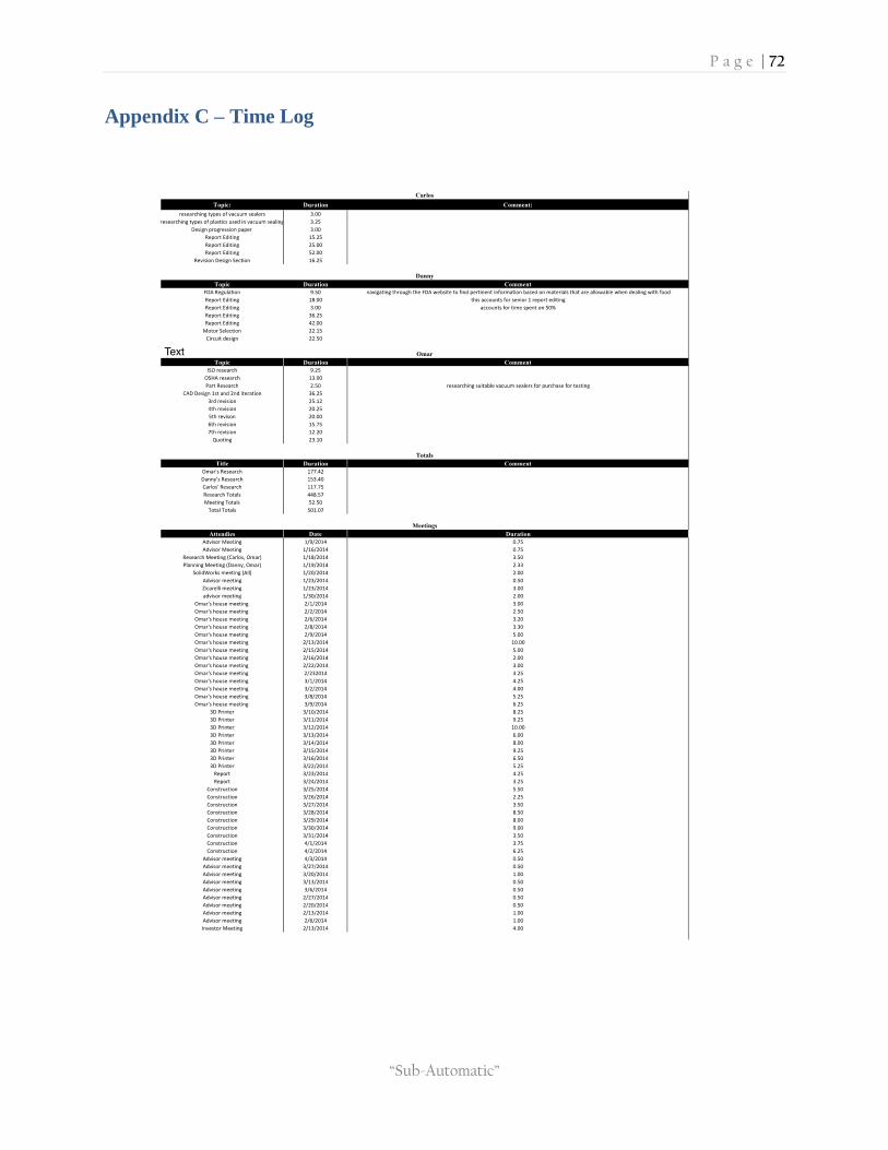
P a g e | 72
“Sub-Automatic”
Appendix C – Time Log

P a g e | 73
“Sub-Automatic”
Appendix D – List of Tasks
Task Person Date Initiated: Date Completed: Comment:
ISO 22,000 & 9,000 research Omar 11/25/2013 10/15/2013 (Danny) to add info to report
Concept Design Danny 11/25/2013 11/15/2013 update the conceptual design to most current
Poster: Timeline All 11/25/2013 11/30/2013 finalize the timeline which will show on poster and in report (choose dates correctly, e tc…)
Report Section (Cost Analysis)PPT All 11/25/2013 12/4/2013
Poster Danny 11/25/2013 12/4/2013 finalize poster information and figure out how this is going to be printed at FIU
Email Karla Danny 1/18/2014 1/19/2014
Contact Norman All 1/18/2014 1/18/2014
Contact Minions Danny 1/18/2014 1/19/2014
Vacuum Sealer Research Carlos 11/25/2013 1/26/2014 Work In Process: research on the various vacuum sealers as well as the plastics used
Group Work Breakdown All 11/25/2013 completed Work In Process
Report Section (Major Components) All 11/25/2013 completed need to add the components we expect to use, with a brief description
First iteration of design (SolidWorks) All 1/18/2014 1/20/2014 Work on Monday 1/20/2014
Design revision (50% Report) Carlos 1/18/2014 1/25/2014 Take from Norman's update
Material Selection (50% Report) Danny 1/18/2014 completed
Mechanism Selection (50%) Carlos 1/18/2014 1/25/2014
Review First Order 1/18/2014 All 1/18/2014 completed Tuesday 1/21/2014.Omar to take order
Cost Analysis (75% Report) Carlos 1/18/2014 completed
Mold CNC Omar 1/18/2014 completed
Research Silicone Belt Omar 1/18/2014 completed
Bearing Analysis (75%) Carlos 1/18/2014 completed
FMEA (100%) All 1/18/2014 completed
ULINE & McMaster Purchase Status Omar 1/18/2014 1/21/2014 Omar to ask if we can purchase from ULINE ( poly bags)
Email Karla Again Danny 1/19/2014 completed Our Decision for here help- received her advise
Stats From Subway All 1/19/2014 completed Weight of a fully loaded sub, avergae number of employed and wages
Find Task For minions All 1/19/2014 completed
alternative forms of manufacturing Omar 1/19/2014 completed
Bearing For Food All 1/20/2014 1/26/2014 FDA approved Mcmaster
order sheet ( 3D filament, Belt, bearings ) Omar 1/26/2014 completed
Second iteration of design (SolidWorks ) Omar 1/20/2014 1/24/2014
Third iteration of design (SolidWorks) Omar 1/20/2014 completed
finalize belt All 2/1/2014 completed
motor order All 2/3/2014 completed Calculations approximate velocity needed
heat sealer All 2/14/2014 completed
Velocity calculations Danny 3/5/2014 completed Determine with velocity
Work on roller diameter Omar 3/5/2014 completed
switch circuit Danny 3/6/2014 completed
Contruction All 3/6/2014 - 3/30/2014 completed
Refinement All 3/29/2014 - 4/3/2014 completed
Future Consideration All 4/2/2014 - 4/10/2014 completed
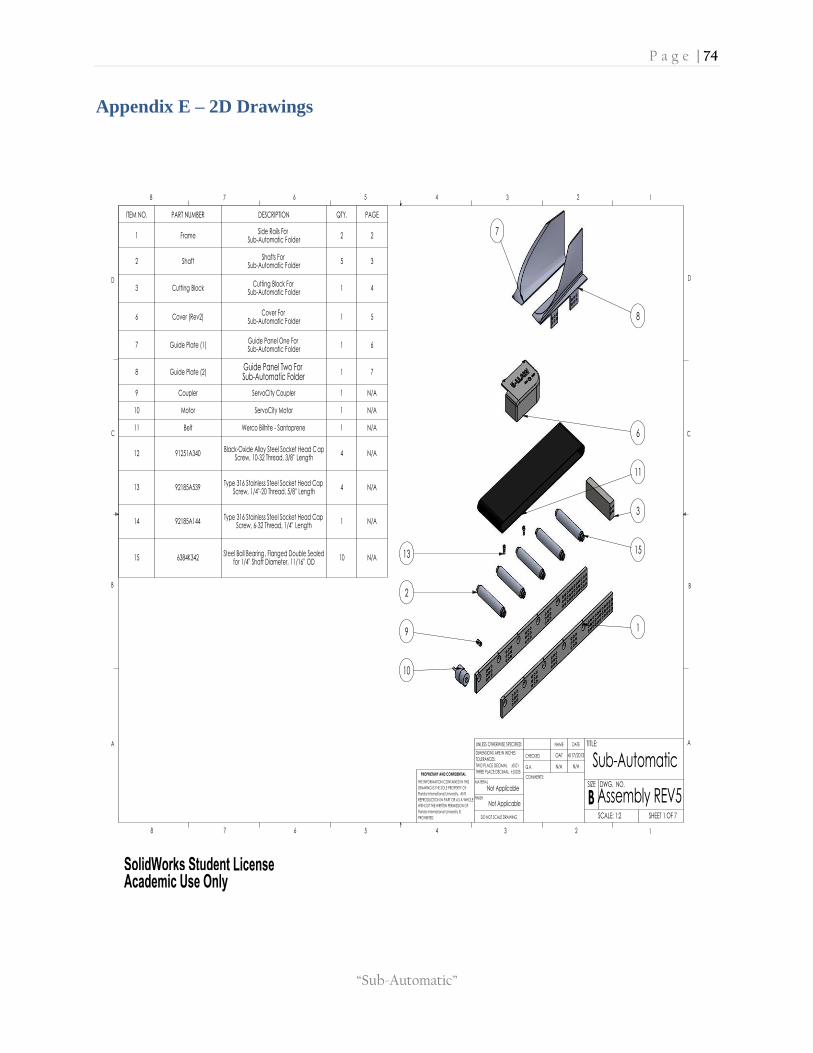
P a g e | 74
“Sub-Automatic”
Appendix E – 2D Drawings
Sub-Automatic
SHEET 1 OF 7
Assembly REV5
D
C
B
AA
B
C
D
12345678
8 7 6 5 4 3
4/17/2013
N/AN/A
OAT
UNLESS OTHERWISE SPECIFIED:
SCALE: 1:2
WITHOUT THE WRITTEN PERMISSION OF
Florida International University IS
THE INFORMATION CONTAINED IN THIS
12
REPRODUCTION IN PART OR AS A WHOLE
Florida International University. ANY
DWG. NO.
PROHIBITED.
PROPRIETARY AND CONFIDENTIAL
DRAWING IS THE SOLE PROPERTY OF
0.005
MATERIAL
FINISH
Not Applicable
Not Applicable
CHECKED
Q.A.
COMMENTS:
DATENAME TITLE:
SIZE
B
DIMENSIONS ARE IN INCHES
TOLERANCES:
TWO PLACE DECIMAL 0.01
THREE PLACE DECIMAL
DO NOT SCALE DRAWING
ITEM NO. PART NUMBER DESCRIPTION QTY. PAGE
1 FrameSide Rails For
Sub-Automatic Folder2 2
2 ShaftShafts For
Sub-Automatic Folder5 3
3 Cutting BlockCutting Block For
Sub-Automatic Folder1 4
6 Cover (Rev2)Cover For
Sub-Automatic Folder1 5
7 Guide Plate (1)Guide Panel One For Sub-Automatic Folder
1 6
8 Guide Plate (2)Guide Panel Two For Sub-Automatic Folder
1 7
9 Coupler ServoCity Coupler 1 N/A
10 Motor ServoCity Motor 1 N/A
11 Belt Werco Biltrite - Santoprene 1 N/A
12 91251A340Black-Oxide Alloy Steel Socket Head C ap
Screw, 10-32 Thread, 3/8" Length4 N/A
13 92185A539Type 316 Stainless Steel Socket Head Cap
Screw, 1/4"-20 Thread, 5/8" Length4 N/A
14 92185A144Type 316 Stainless Steel Socket Head Cap
Screw, 6-32 Thread, 1/4" Length1 N/A
15 6384K342Steel Ball Bearing, Flanged Double Sealed
for 1/4" Shaft Diameter, 11/16" OD10 N/A
1
10
9
2
7
8
6
11
3
1513
SolidWorks Student License Academic Use Only

P a g e | 75
“Sub-Automatic”
TAG X LOC Y LOC SIZE
A1 0.63 1.41 0.72 THRU ALL
A2 4.88 1.41 0.72 THRU ALL
A3 9.13 1.41 0.72 THRU ALL
A4 13.38 1.41 0.72 THRU ALL
A5 17.63 1.41 0.72 THRU ALL
B1 2.75 0.91 0.27 THRU ALL
B2 7.00 0.91 0.27 THRU ALL
B3 11.25 0.91 0.27 THRU ALL
B4 15.50 0.91 0.27 THRU ALL
B5 19.25 0.91 0.27 THRU ALL
TAG X LOC Y LOC SIZE
1 0.63 0.19 0.15 0.71
10-24 UNC 0.58
2 4.88 0.19 0.15 0.71
10-24 UNC 0.58
3 9.13 0.19 0.15 0.71
10-24 UNC 0.58
4 13.38 0.19 0.15 0.71
10-24 UNC 0.58
5 17.63 0.19 0.15 0.71
10-24 UNC 0.58
D
C
B
AA
B
C
D
12345678
8 7 6 5 4 3 2 1
THE INFORMATION CONTAINED IN THIS
DRAWING IS THE SOLE PROPERTY OF
Florida International University. ANY
REPRODUCTION IN PART OR AS A WHOLE
WITHOUT THE WRITTEN PERMISSION OF
Florida International University IS
PROHIBITED.
PROPRIETARY AND CONFIDENTIAL
DIMENSIONS ARE IN INCHES
TOLERANCES:
TWO PLACE DECIMAL 0.01
THREE PLACE DECIMAL 0.005
MATERIAL
FINISH
6061-T6 (SS)
As Machined
CHECKED
Q.A.
COMMENTS:
DATENAME TITLE:
SIZE
BDWG. NO.
SCALE: 1:2
UNLESS OTHERWISE SPECIFIED:
OAT
N/A N/A
4/17/2013
Sub-Automatic
SHEET 2 OF 7
Assembly REV5DO NOT SCALE DRAWING
51 2 3 4
X
Y
00
5 x 0.15in 3.80mm 0.71in 17.91mm
10-24 UNC 0.58in 14.73mm
9
.53
mm
0.3
8in
B5
A1
B1
A2
B2
A3
B3
A4
B4
A5
X
Y
00
431.80mm
17.00in
5
0.8
0m
m2
.00
in
609.60mm
24.00in
5
11
SolidWorks Student License Academic Use Only

P a g e | 76
“Sub-Automatic”
D
C
B
AA
B
C
D
12345678
8 7 6 5 4 3 2 1
THE INFORMATION CONTAINED IN THIS
DRAWING IS THE SOLE PROPERTY OF
Florida International University. ANY
REPRODUCTION IN PART OR AS A WHOLE
WITHOUT THE WRITTEN PERMISSION OF
Florida International University IS
PROHIBITED.
PROPRIETARY AND CONFIDENTIAL
DIMENSIONS ARE IN INCHES
TOLERANCES:
TWO PLACE DECIMAL 0.01
THREE PLACE DECIMAL 0.005
MATERIAL
FINISH
6061-T6 (SS)
Machined
CHECKED
Q.A.
COMMENTS:
DATENAME TITLE:
SIZE
BDWG. NO.
SCALE: 1:2
UNLESS OTHERWISE SPECIFIED:
OAT
N/A N/A
4/17/2013
Sub-Automatic
SHEET 3 OF 7
Assembly REV5DO NOT SCALE DRAWING
A
A
SECTION A-A SCALE 1 : 1
151.13mm
5.95in
124.46mm
4.90in
-0
.00
0
6.3
5m
m0
.25
in
+.0
01
2
25
.40
mm
1.0
0in
SolidWorks Student License Academic Use Only

P a g e | 77
“Sub-Automatic”
D
C
B
AA
B
C
D
12345678
8 7 6 5 4 3 2 1
THE INFORMATION CONTAINED IN THIS
DRAWING IS THE SOLE PROPERTY OF
Florida International University. ANY
REPRODUCTION IN PART OR AS A WHOLE
WITHOUT THE WRITTEN PERMISSION OF
Florida International University IS
PROHIBITED.
PROPRIETARY AND CONFIDENTIAL
DIMENSIONS ARE IN INCHES
TOLERANCES:
TWO PLACE DECIMAL 0.01
THREE PLACE DECIMAL 0.005
MATERIAL
FINISH
N/A
N/A
CHECKED
Q.A.
COMMENTS:
DATENAME TITLE:
SIZE
BDWG. NO.
SCALE: 1:2
UNLESS OTHERWISE SPECIFIED:
OAT
N/A N/A
4/17/2013
Sub-Automatic
SHEET 5 OF 7
Assembly REV5DO NOT SCALE DRAWING
4
8.2
6m
m1
.90
in
1
8.5
9m
m0
.73
in
39mm1.54in
107.95mm
4.25in
9
5.2
5m
m3
.75
in
88.90mm3.50in
12.95mm
0.51in
3mmR0.12in
9.50mm0.37in
2
0.7
5m
m0
.8
2in
SolidWorks Student License Academic Use Only

P a g e | 78
“Sub-Automatic”
D
C
B
AA
B
C
D
12345678
8 7 6 5 4 3 2 1
THE INFORMATION CONTAINED IN THIS
DRAWING IS THE SOLE PROPERTY OF
Florida International University. ANY
REPRODUCTION IN PART OR AS A WHOLE
WITHOUT THE WRITTEN PERMISSION OF
Florida International University IS
PROHIBITED.
PROPRIETARY AND CONFIDENTIAL
DIMENSIONS ARE IN INCHES
TOLERANCES:
TWO PLACE DECIMAL 0.01
THREE PLACE DECIMAL 0.005
MATERIAL
FINISH
Acrylic (Medium-high impact)
Machined
CHECKED
Q.A.
COMMENTS:
DATENAME TITLE:
SIZE
BDWG. NO.
SCALE: 1:2
UNLESS OTHERWISE SPECIFIED:
OAT
N/A N/A
4/17/2013
Sub-Automatic
SHEET 6 OF 7
Assembly REV5DO NOT SCALE DRAWING
1
30
.81
mm
5.1
5in
1
71
.45
mm
6.75
in
254mm
10.00in
107.95
4.25
SolidWorks Student License Academic Use Only

P a g e | 79
“Sub-Automatic”
D
C
B
AA
B
C
D
12345678
8 7 6 5 4 3 2 1
THE INFORMATION CONTAINED IN THIS
DRAWING IS THE SOLE PROPERTY OF
Florida International University. ANY
REPRODUCTION IN PART OR AS A WHOLE
WITHOUT THE WRITTEN PERMISSION OF
Florida International University IS
PROHIBITED.
PROPRIETARY AND CONFIDENTIAL
DIMENSIONS ARE IN INCHES
TOLERANCES:
TWO PLACE DECIMAL 0.01
THREE PLACE DECIMAL 0.005
MATERIAL
FINISH
Acrylic (Medium-high impact)
Machined
CHECKED
Q.A.
COMMENTS:
DATENAME TITLE:
SIZE
BDWG. NO.
SCALE: 1:2
UNLESS OTHERWISE SPECIFIED:
OAT
N/A N/A
4/17/2013
Sub-Automatic
SHEET 7 OF 7
Assembly REV5DO NOT SCALE DRAWING
1
30
.81
mm
5.1
5in
1
71
.45
mm
6.75
in
73.87mm
2.91in
259.21mm
10.21in
107.95
4.25
SolidWorks Student License Academic Use Only

P a g e | 80
“Sub-Automatic”
SECTION B-B SCALE 1 : 1
132.08mm 5.20in
4
6.7
1m
m1
.84
in
A2
B1
B2
A1
X
Y
00
22.23mm
0.88in
B
B
TAG X LOC Y LOC SIZE
A1 0.19 0.75 0.25 THRU ALL
A2 0.19 1.25 0.25 THRU ALL
B1 0.69 0.75 0.25 THRU
B2 0.69 1.25 0.25 THRU
Sub-Automatic
Assembly REV5
D
C
B
AA
B
C
D
12345678
8 7 6 5 4 3 2
4/17/2013
B
N/AN/A
OAT
UNLESS OTHERWISE SPECIFIED:
Florida International University IS
PROHIBITED.
WITHOUT THE WRITTEN PERMISSION OF
THE INFORMATION CONTAINED IN THIS
1
REPRODUCTION IN PART OR AS A WHOLE
Florida International University. ANY
SCALE: 1:2
PROPRIETARY AND CONFIDENTIAL
DRAWING IS THE SOLE PROPERTY OF
0.005
SHEET 4 OF 7
MATERIAL
PBT General Purpose
Machined
CHECKED
Q.A.
COMMENTS:
DATENAME TITLE:
SIZE
FINISH
DWG. NO.
DIMENSIONS ARE IN INCHES
TOLERANCES:
TWO PLACE DECIMAL 0.01
THREE PLACE DECIMAL
DO NOT SCALE DRAWING
SolidWorks Student License Academic Use Only

P a g e | 81
“Sub-Automatic”
Appendix F – Failure Mode & Effects Analysis (FMEA)
Pro
cess
ste
pP
ote
nti
al
fail
ure
mo
de
Po
ten
tia
l fa
ilu
re e
ffe
cts
S E V
Po
ten
tia
l ca
use
s
O C C
Cu
rre
nt
pro
cess
co
ntr
ols
D E T
R P N
Act
ion
s
reco
mm
en
de
d
Re
spo
nsi
bil
ity
(ta
rge
t
da
te)
Act
ion
s ta
ken
N e w
S E V
N e w
O C C
N e w
D E T
N e w
R P N
Wha
t is
the
step
?
In w
hat
way
s ca
n th
e st
ep
go w
rong
?
Wha
t is
the
impa
ct o
n th
e
cust
omer
if t
he fa
ilure
mod
e
is n
ot p
reve
nted
or
corr
ecte
d?
10
Wha
t ca
uses
the
ste
p to
go
wro
ng?
(i.e
., H
ow c
ould
the
failu
re m
ode
occu
r?)
10
Wha
t ar
e th
e ex
istin
g co
ntro
ls
that
eith
er p
reve
nt t
he fa
ilure
mod
e fro
m o
ccur
ring
or d
etec
t it
shou
ld it
occ
ur?
1010
00
Wha
t ar
e th
e ac
tions
for
redu
cing
the
occu
rren
ce o
f the
caus
e or
for
impr
ovin
g
its d
etec
tion?
You
shou
ld p
rovi
de a
ctio
ns
on a
ll hi
gh R
PN
s an
d
on s
ever
ity r
atin
gs o
f 9
or 1
0.
Who
is r
espo
nsib
le fo
r
the
reco
mm
ende
d
actio
n? W
hat
date
shou
ld it
be
com
plet
ed
by?
Wha
t w
ere
the
actio
ns
impl
emen
ted?
Incl
ude
com
plet
ion
mon
th/y
ear
(the
n re
calc
ulat
e
resu
lting
RP
N).
1010
1010
00
2B
earin
g F
ailu
re
Dep
endi
ng o
n th
e nu
mbe
r of
bear
ings
tha
t fa
il, t
he im
pact
is d
iffer
ent.
Mac
hine
has
10
bear
ings
tot
al.
Sho
uld
one
or
two
fail,
the
mac
hine
wou
ld
still
be
able
to
func
tion;
how
ever
any
mor
e th
an t
hat
the
inte
grity
of t
he m
achi
ne
may
be
com
prom
ised
6E
xcee
d th
e ca
talo
g ra
ting
of
the
bear
ings
1V
isua
l Ins
pect
ion
212
Ens
urin
g th
at o
nly
sand
wic
hes
are
plac
ed
on t
he m
achi
ne
Em
ploy
ees/
Man
ager
N
/A6
11
6
1DS
witc
h F
ailu
re
Sho
uld
the
switc
h fa
il, t
he
mot
or w
ill n
ot h
ave
pow
er
rout
ed t
o it
and
ther
efor
wou
ld n
ot d
eliv
er p
ower
to
the
conv
eyor
bel
t
8
Pos
sibl
e el
ectr
ical
failu
re;
the
switc
h co
uld
have
bee
n po
orly
sold
ered
dur
ing
man
ufac
turin
g
and
asse
mbl
y; p
ossi
bilit
y of
a
defe
ctiv
e sw
itch
1N
one
18
Pos
sibi
lity
of
incr
easi
ng q
ualit
y
cont
rol o
n m
otor
mod
ules
bef
ore
asse
mbl
ing
with
the
final
mac
hine
Man
ufac
ture
r/A
ssem
bl
erN
/A8
11
8
1CM
otor
Fai
lure
Mot
or d
oes
not
wor
k an
d th
e
conv
eyor
bel
t do
es n
ot h
ave
pow
er b
eing
del
iver
ed t
o it
8
Che
ck t
hat
the
pow
er is
prop
erly
con
nect
ed;
that
the
switc
h is
tur
ned
'on'
. If
the
prev
ious
tw
o m
etho
ds d
o no
t
prod
uce
wor
king
res
ults
,
repl
acem
ent
of t
he m
otor
mod
ule
may
be
nece
ssar
y
4N
one
264
Usi
ng q
ualit
y bu
ilt D
C
mot
ors
coul
d re
duce
the
poss
ibili
ty o
f a
mec
hani
cal f
ailu
re.
Alth
ough
the
mot
or is
encl
osed
, en
sure
no
debr
is is
abl
e to
affe
ct
the
mot
or
Em
ploy
ees/
Man
ager
N
/A8
41
32
1BS
andw
ich
gets
fold
ed
inco
rrec
tly
The
sand
wic
h m
ay n
ot e
nter
the
narr
owin
g ch
anne
l
corr
ectly
or
get
caug
ht,
caus
ing
it to
not
be
fold
ed
corr
ectly
4
Pla
cing
the
san
dwic
h
inco
rrec
tly o
n th
e co
nvey
or
belt;
pla
cing
the
cut
end
firs
t
coul
d po
tent
ially
cau
se t
he
sand
wic
h to
cat
ch o
n th
e ed
ge
of t
he fo
ldin
g ch
anne
l.
9P
rope
rly in
stru
ct t
he o
pera
tor
136
Inst
ruct
the
ope
rato
r to
plac
e th
e sa
ndw
ich
'but
t-en
d' fi
rst
inst
ead
of t
he c
ut e
nd,
to
prev
ent
this
from
occu
ring
Em
ploy
ees/
Man
ager
N
/A4
71
28
1AC
onve
yor
Bel
t m
alfu
nctio
n
The
mac
hine
will
not
be
able
to p
erfo
rm t
he d
esig
ned
func
tion
of fo
ldin
g th
e
sand
wic
h
7
Pos
sibl
e fra
ying
of t
he a
ctua
l
belt;
a s
mal
l cut
cou
ld
prop
agat
e al
ong
the
belt
caus
ing
the
entir
e be
lt to
sepa
rate
3D
aily
vis
ual i
nspe
ctio
n1
21
Incr
ease
the
num
ber
of
insp
ectio
ns fr
om
wee
kly
to d
aily
, or
daily
to
twic
e a
day
(bef
ore
open
ing
and
afte
r cl
osin
g)
Em
ploy
ees/
Man
ager
N
/A7
21
14

P a g e | 82
“Sub-Automatic”
16. References
1Fda.gov.
Food Code 2009
In-text: (Fda.gov, 2013)
Bibliography: Fda.gov. 2013. Food Code 2009. [online] Available at:
http://www.fda.gov/Food/GuidanceRegulation/RetailFoodProtection/FoodCode/UCM2019396.htm [Accessed: 5 Nov 2013].
Vacuum Schematics
http://www.pleasanthillgrain.com/vacuum_packaging_machine_food_sealer_packing_machines.aspx
Heat Sealers
http://www.industrialsupplies.com/displayproductdetail.do?skuSearch=Q52634&mr:referralID=NA&ite
mGroupOID=165408&origin=pla&cid=pla_goog&9gtype=search&mr:filter=51436252777&baseItemOI
D=165408&mr:ad=25000371577&mr:trackingCode=F1763EA3-02AF-E011-87D9-
001B21A69EB8&source=google_pla&sku=199730&mr:device=c&mr:adType=pla
Shigley's Mechanical Engineering Design, Richard G. Budynas, J. Keith Nisbett, Ninth edition, January 29 2010.