self-stabilization of an optical frequency comb using … of an optical frequency comb using a...
TRANSCRIPT

Self-stabilization of an optical frequency combusing a short-path-length interferometerJAMES P. CAHILL,1,* WEIMIN ZHOU,1 AND CURTIS R. MENYUK2
1U.S. Army Research Laboratory, 2800 Powder Mill Road, Adelphi, Maryland 20783, USA2Department of Computer Science and Electrical Engineering, University of Maryland: Baltimore County, 1000 Hilltop Circle, Baltimore,Maryland 21250, USA*Corresponding author: [email protected]
Received 20 February 2017; revised 30 March 2017; accepted 31 March 2017; posted 31 March 2017 (Doc. ID 286730); published 20 April 2017
We stabilized the repetition rate of an optical frequencycomb using a self-referenced phase-locked loop. Thephase-locked loop generated its error signal with a fiber-optic delay-line interferometer that had a path-lengthdifference of 8 m. We used the stabilized repetition rateto generate a 10 GHz signal with a single-sideband phasenoise that was limited by environmental noise to−120 dBc∕Hz at an offset frequency of 1 kHz. Modelingresults indicate that thermoconductive noise sets a funda-mental phase noise limit for an 8 m interferometer of−152 dBc∕Hz at a 1 kHz offset frequency. The short lengthof the interferometer indicates that it could be realized as aphotonic integrated circuit, which may lead to a chip-scalestabilized optical frequency comb with an ultralow-phase-noise repetition rate. © 2017 Optical Society of America
OCIS codes: (140.3425) Laser stabilization; (060.5625) Radio
frequency photonics; (140.7090) Ultrafast lasers; (140.4050)
Mode-locked lasers.
https://doi.org/10.1364/OL.42.001680
A multitude of systems, including radar, remote sensing, very-long-baseline interferometry, and quantum information sys-tems, require microwave frequency sources that generate signalsat 10 GHz and higher with ultralow phase noise. These systemswill benefit from ultralow-phase-noise frequency sources thatare compact, inexpensive, and scalable to mass production.Optical cavities, such as ultralow expansion glass Fabry–Perot cavities or crystalline whispering gallery mode resonators,have been used to generate optical frequencies that are exceed-ingly stable over short time scales [1,2], reaching Allan devia-tions, for example, of approximately 1 × 10⁻¹⁶ at 1 s. Whenthese optical frequencies are coherently divided, they produceultralow-phase-noise microwave signals. Optical frequencycombs (OFCs) have emerged as an elegant way to perform thiscoherent frequency division [3]. This technique has led to thegeneration of signals at numerous frequencies from 5 MHz to10 GHz with record-breaking low-phase-noise levels [4,5].However, the Fabry–Perot cavities and whispering gallery moderesonators that achieve the lowest phase noise typically require
extensive environmental isolation, are hand-manufactured, andcannot be monolithically integrated. These factors result in afrequency source that is necessarily large and expensive.
An alternative approach is to use an optical delay-line inter-ferometer, such as an asymmetric Mach–Zehnder interferom-eter (AMZI) or Michelson interferometer, to measure the phasenoise of the OFC’s repetition rate and cancel it in real timeusing a phase-locked loop (PLL). This technique has been usedto narrow the linewidth of continuous-wave lasers to less than1 Hz [6–9] and ultimately achieved a frequency stability of 7 ×10⁻¹⁵ at 1 s using a fiber-optic interferometer with a path-length difference of 500 m [9]. The technique has also beenapplied to an OFC in order to generate a 10 GHz signal witha phase noise of −130 dBc∕Hz at 1 kHz offset frequencyusing a fiber-optic interferometer with a 2 km path-lengthdifference [10]. Because of their simple architecture, delay-lineinterferometers with short-path-length imbalances can bemonolithically integrated using a straightforward and scalablemanufacturing process. However, the delay lengths used in theexisting literature are too long to be achieved on anintegrated platform.
In the work reported in this Letter, we investigated the phasenoise limits of the repetition rate of an OFC that was stabilizedusing a short-path-length AMZI. We used an AMZI with an8 m path imbalance to generate a 10 GHz signal with a phasenoise of −120 dBc∕Hz at a 1 kHz offset frequency. In addition,we developed a model that accounts for environmental, ther-moconductive, RF-component, and shot noise. We found thatthe thermoconductive and RF noise contributions rise as thedelay length is decreased, while the environmental and shotnoise contributions remain constant. Thus, when using anAMZI-stabilized OFC to generate a low-phase-noise micro-wave, the phase noise requirements will set a minimum lengthfor the AMZI path imbalance. We compared the model andexperimental results and found that the phase noise of the10 GHz signal was dominated by environmental noise at offsetfrequencies below 10 kHz and by shot noise at offset frequen-cies above 10 kHz. Both of these noise sources could be mi-tigated in future work. The model further indicated that ifthe environmental and shot noise contributions were mitigated,the ultimate phase noise limitation when using an 8 m long
1680 Vol. 42, No. 9 / May 1 2017 / Optics Letters Letter
0146-9592/17/091680-04 Journal © 2017 Optical Society of America
delay would be the thermoconductive noise. We estimatedthis limitation to be −152 dBc∕Hz at a 1 kHz offset. A pathdifference of less than 10 m indicates that this stabilizationscheme could be realized as a photonic integrated circuit.Low-loss optical delay lines as long as 29 m have been demon-strated using monolithic integrated Si3N4 waveguides [11]. Incombination with the development of integrated Kerr-combOFCs [12,13], this technology may provide a small-scale,fully integrated method to generate ultralow-phase-noisemicrowaves.
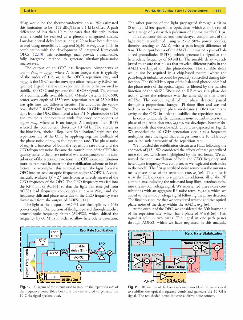
The output of an OFC has frequency components atωN � Nωr � ωCEO, where N is an integer that is typicallyof the order of 105, ωr is the OFC’s repetition rate, andωCEO is the OFC’s carrier-envelope offset frequency (CEO fre-quency). Figure 1 shows the experimental setup that we used tostabilize the OFC and generate the 10 GHz signal. The outputof a commercially available OFC (Menlo Systems FC-1500,center wavelength of 1550 nm, repetition rate of 250 MHz)was split into two different circuits. The circuit in the yellowbox, labeled “10 GHz Out,” generated the 10 GHz signal. Thelight from the OFC illuminated a fast P-I-N photodiode (PD)and excited a photocurrent with frequency components atωm � mωr, where m is an integer. A bandpass filter (BPF)selected the component closest to 10 GHz. The circuit inthe blue box, labeled “Rep. Rate Stabilization,” stabilized therepetition rate of the OFC by applying negative feedback ofthe phase noise of ωN to the repetition rate. The phase noiseof ωN is a function of both the repetition rate noise and theCEO-frequency noise. Because the contribution of the CEO-fre-quency noise to the phase noise of ωN is comparable to the con-tribution of the repetition rate noise, the CEO noise contributionmust be removed in order for the stabilization scheme to be ef-fective. To accomplish this removal, we sent the light from theOFC into an acousto-optic frequency shifter (AOFS1). A com-mercially available 1f − 2f interferometer directly measured theCEO frequency of the OFC. The CEO frequency was fed intothe RF input of AOFS1, so that the light that emerged fromAOFS1 had frequency components at ωN � Nωr, and thefrequency shift and phase noise due to the CEO frequency wereeliminated from the output of AOFS1 [14].
The light at the output of AOFS1 was then split by a 50%power coupler. One portion of the light passed through anotheracousto-optic frequency shifter (AOFS2), which shifted thefrequency by 60 MHz in order to allow heterodyne detection.
The other portion of the light propagated through a 40 ns(8 m) hybrid free-space/fiber-optic delay, which could be tunedover a range of 3 ns with a precision of approximately 0.1 ps.
The frequency-shifted and time-delayed components of thelight were recombined using a 2 × 2 50% power coupler,thereby creating an AMZI with a path-length difference of8 m. The output beams of the AMZI illuminated a pair of bal-anced photodiodes (BPDs), which generated a signal at theheterodyne frequency of 60 MHz. The tunable delay was ad-justed to ensure that pulses that traveled different paths in theAMZI overlapped on the photodiodes. The tunable delaywould not be required in a chip-based system, where thepath-length imbalance could be precisely controlled during fab-rication. The 60 MHz output of the balanced photodiodes hadthe phase noise of the optical signal, as filtered by the transferfunction of the AMZI. We used an RF mixer as a phase de-tector, where the reference was the same signal that droveAOFS2. The output signal of the phase detector passedthrough a proportional-integral (PI-)loop filter and was fedback to an electro-optic phase modulator (EOM) within thecavity of the OFC in order to stabilize the repetition rate.
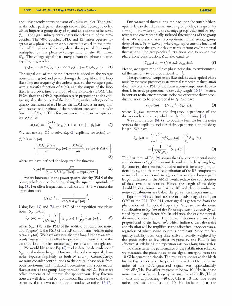
In order to identify the dominant noise contributions to thephase of the repetition rate, ϕr�ω�, we developed Fourier-do-main models that describe each circuit, as depicted in Fig. 2.We modeled the 10 GHz generation circuit as a frequencymultiplier since the signal that emerges from the 10 GHz out-put is the mth harmonic of the repetition rate.
We modeled the stabilization circuit as a PLL, following theapproach of [15]. We considered the effects of three generalizednoise sources, which are highlighted by the red boxes. We as-sumed that the cancellation of both the CEO frequency andheterodyne frequency was complete, so we neglected their noisein the model. The first generalized noise source was the instanta-neous phase noise of the repetition rate, ϕ0�ω�. This noise iswhat the PLL operates to suppress. In addition, all of the RFcomponents, including the mixer and loop filter, introduce noiseinto the in-loop voltage signal. We represented these noise con-tributions with an aggregate RF noise term, vRF�ω�, which weadded to the in-loop voltage signal following the phase detector.The final noise source that we considered was the additive opticalphase noise of the delay within the AMZI, ϕopt�ω�.
At the output of the OFC, we considered theN th harmonicof the repetition rate, which has a phase of N × ϕr�ω�. Thissignal is split in two paths. The signal in one path passesthrough AOFS2, which we have neglected in this analysis,
Fig. 1. Diagram of the circuit used to stabilize the repetition rate ofthe frequency comb (blue box) and the circuit used to generate the10 GHz signal (yellow box).
Fig. 2. Illustration of the Fourier-domain model of the circuits usedto stabilize the optical frequency comb and generate the 10 GHzsignal. The red-shaded boxes indicate additive noise sources.
Letter Vol. 42, No. 9 / May 1 2017 / Optics Letters 1681
and subsequently enters one arm of a 50% coupler. The signalin the other path passes through the tunable fiber-optic delay,which imparts a group delay of τ0 and an additive noise term,ϕopt. The signal subsequently enters the other arm of the 50%coupler. The 50% coupler, BPD, and RF mixer operate to-gether as a phase detector whose output is equal to the differ-ence of the phases of the signals at the input of the couplermultiplied by the phase-to-voltage ratio of the RF mixer,K D. The voltage signal that emerges from the phase detector,vPD�ω�, is given by
vPD�ω� � NK D�ϕr�ω� − e−jωτ0ϕr�ω�� � K Dϕopt�ω�: (1)
The signal out of the phase detector is added to the voltagenoise term vRF�ω� and passes through the loop filter. The loopfilter imparts frequency-dependent gain to the voltage signalwith a transfer function of F �ω�, and the output of the loopfilter is fed back into the input of the intracavity EOM. TheEOM alters the OFC’s repetition rate in proportion to the volt-age signal at the output of the loop filter, with a voltage-to-fre-quency coefficient of K . Hence, the EOM acts as an integratorwith respect to the phase of the repetition rate, with a transferfunction of K ∕jω. Therefore, we can write a recursive equationfor ϕr�ω� as
ϕr�ω� �F�ω�Kjω
�vPD�ω� � vRF�ω�� � ϕ0�ω�: (2)
We can use Eq. (1) to solve Eq. (2) explicitly for ϕr�ω� asϕr�ω� � H �ω�
×�K K DF�ω�
jωϕopt�ω� �
K F�ω�jω
vRF�ω� � ϕ0�ω��;
(3)where we have defined the loop transfer function
H �ω� ≡ jωjω − NKK DF �ω��1 − exp�−jωτ0��
: (4)
We are interested in the power spectral density (PSD) of thephase, which can be found by taking the square magnitude ofEq. (3). For offset frequencies for which ωτ0 ≪ 1, we make theapproximation
jH �ω�j2 ≈���� 1
N τ0K K DF �ω�
����2
: (5)
Using Eqs. (3) and (5), the PSD of the repetition rate phasenoise, Sϕ;r�ω�, is
Sϕ;r�ω� ��
1
N τ0ω
�2�Sϕ;opt�ω� �
1
K 2D
Sv;RF�ω��; (6)
where Sϕ;opt�ω� is the PSD of the additive optical phase noise,and Sv;RF�ω� is the PSD of the RF components’ voltage noiseterm, vRF�ω�. We have assumed that the loop filter has an arbi-trarily large gain for the offset frequencies of interest, so that thecontribution of the instantaneous phase noise can be neglected.
We would like to use Eq. (6) to elucidate the dependence ofSϕ;r on the delay length. However, the additive optical phasenoise depends implicitly on both N and τ0. Consequently,we must consider contributions to the optical phase noise fromboth environmentally induced fluctuations and spontaneousfluctuations of the group delay through the AMZI. For mostoffset frequencies of interest, the spontaneous delay fluctua-tions are well described by spontaneous fluctuations of the tem-perature, also known as the thermoconductive noise [16,17].
Environmental fluctuations impinge upon the tunable fiber-optic delay, so that the instantaneous group delay, τ, is given byτ � τ0 � δτ, where τ0 is the average group delay and δτ rep-resents the environmentally induced fluctuations of the groupdelay. We assumed that δτ is proportional to the average groupdelay. Hence, δτ � τ0δxenv, where xenv represents the fractionalfluctuations of the group delay that result from environmentalfluctuations. The group-delay fluctuations lead to an additivephase noise contribution, ϕenv�ω�, equal to
Sϕ;env�ω� � �Nωrτ0�2Sx;env�ω�: (7)
Hence, we expect the additive phase noise due to environmen-tal fluctuations to be proportional to τ20.
The spontaneous temperature fluctuations cause optical phasenoise by the same processes as an external temperature fluctuationdoes; however, the PSD of the spontaneous temperature fluctua-tions is inversely proportional to the delay length [16,17]. Hence,in contrast to the environmental noise, we expect the thermocon-ductive noise to be proportional to τ0. We have
Sϕ;TC�ω� � �Nωr�2τ0STC�ω�; (8)
where STC�ω� represents the frequency dependence of thethermoconductive noise, which can be found using [17].
We combine Eqs. (6)–(8) to obtain a formula for the noisesources that explicitly includes their dependencies on the delaylength. We have
Sϕ;r�ω� ��1
ω
�2�ω2r Sx;env�ω� �
ω2r
τ0STC�ω�
��
1
NK Dτ0
�2
Sv;RF�ω��: (9)
The first term of Eq. (9) shows that the environmental noisecontribution to Sϕ;r�ω� does not depend on the delay length τ0.By contrast, the thermoconductive noise is inversely propor-tional to τ0, and the noise contribution of the RF componentsis inversely proportional to τ20, so that using a longer path-length difference in the AMZI would reduce the contributionof these two noise sources. Hence, the length of the delayshould be determined, so that the RF and thermoconductivenoise contributions are below the phase noise requirement.
Equation (9) also elucidates the main advantage of using anOFC in the PLL. The PLL error signal is generated from thephase noise of the optical frequency, Nωr, so that the noisecontribution to Sϕ;r�ω� of the RF components is effectively di-vided by the large factor N 2. In addition, the environmental,thermoconductive, and RF noise contributions are inverselyproportional to the factor ω2, which indicates that the noisecontribution will be amplified as the offset frequency decreases,regardless of which noise source is dominant. Since the fre-quency stability over long time scales is heavily weighted bythe phase noise at low offset frequencies, the PLL is lesseffective at stabilizing the repetition rate over long time scales.
To characterize the performance of the stabilization scheme,we measured the phase noise of the signal emerging from the10 GHz generation circuit. The results are shown as the blackline in Fig. 3. For offset frequencies above 10 kHz, the phasenoise of the OFC-generated signal was approximately−144 dBc∕Hz. For offset frequencies below 10 kHz, its phasenoise rose sharply, reaching approximately −120 dBc∕Hz at1 kHz and approaching −40 dBc∕Hz at 10 Hz. The phasenoise level at an offset of 10 Hz indicates that the
1682 Vol. 42, No. 9 / May 1 2017 / Optics Letters Letter
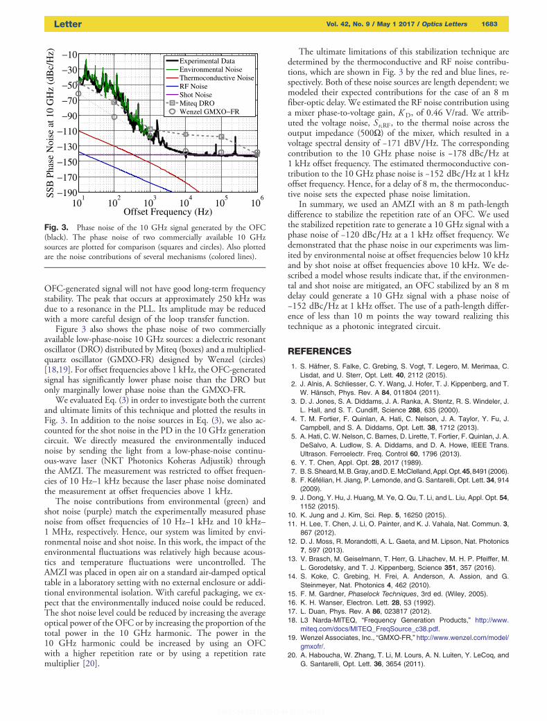
OFC-generated signal will not have good long-term frequencystability. The peak that occurs at approximately 250 kHz wasdue to a resonance in the PLL. Its amplitude may be reducedwith a more careful design of the loop transfer function.
Figure 3 also shows the phase noise of two commerciallyavailable low-phase-noise 10 GHz sources: a dielectric resonantoscillator (DRO) distributed by Miteq (boxes) and a multiplied-quartz oscillator (GMXO-FR) designed by Wenzel (circles)[18,19]. For offset frequencies above 1 kHz, the OFC-generatedsignal has significantly lower phase noise than the DRO butonly marginally lower phase noise than the GMXO-FR.
We evaluated Eq. (3) in order to investigate both the currentand ultimate limits of this technique and plotted the results inFig. 3. In addition to the noise sources in Eq. (3), we also ac-counted for the shot noise in the PD in the 10 GHz generationcircuit. We directly measured the environmentally inducednoise by sending the light from a low-phase-noise continu-ous-wave laser (NKT Photonics Koheras Adjustik) throughthe AMZI. The measurement was restricted to offset frequen-cies of 10 Hz–1 kHz because the laser phase noise dominatedthe measurement at offset frequencies above 1 kHz.
The noise contributions from environmental (green) andshot noise (purple) match the experimentally measured phasenoise from offset frequencies of 10 Hz–1 kHz and 10 kHz–1 MHz, respectively. Hence, our system was limited by envi-ronmental noise and shot noise. In this work, the impact of theenvironmental fluctuations was relatively high because acous-tics and temperature fluctuations were uncontrolled. TheAMZI was placed in open air on a standard air-damped opticaltable in a laboratory setting with no external enclosure or addi-tional environmental isolation. With careful packaging, we ex-pect that the environmentally induced noise could be reduced.The shot noise level could be reduced by increasing the averageoptical power of the OFC or by increasing the proportion of thetotal power in the 10 GHz harmonic. The power in the10 GHz harmonic could be increased by using an OFCwith a higher repetition rate or by using a repetition ratemultiplier [20].
The ultimate limitations of this stabilization technique aredetermined by the thermoconductive and RF noise contribu-tions, which are shown in Fig. 3 by the red and blue lines, re-spectively. Both of these noise sources are length dependent; wemodeled their expected contributions for the case of an 8 mfiber-optic delay. We estimated the RF noise contribution usinga mixer phase-to-voltage gain, K D, of 0.46 V/rad. We attrib-uted the voltage noise, Sv;RF, to the thermal noise across theoutput impedance (500Ω) of the mixer, which resulted in avoltage spectral density of −171 dBV∕Hz. The correspondingcontribution to the 10 GHz phase noise is −178 dBc∕Hz at1 kHz offset frequency. The estimated thermoconductive con-tribution to the 10 GHz phase noise is −152 dBc∕Hz at 1 kHzoffset frequency. Hence, for a delay of 8 m, the thermoconduc-tive noise sets the expected phase noise limitation.
In summary, we used an AMZI with an 8 m path-lengthdifference to stabilize the repetition rate of an OFC. We usedthe stabilized repetition rate to generate a 10 GHz signal with aphase noise of −120 dBc∕Hz at a 1 kHz offset frequency. Wedemonstrated that the phase noise in our experiments was lim-ited by environmental noise at offset frequencies below 10 kHzand by shot noise at offset frequencies above 10 kHz. We de-scribed a model whose results indicate that, if the environmen-tal and shot noise are mitigated, an OFC stabilized by an 8 mdelay could generate a 10 GHz signal with a phase noise of−152 dBc∕Hz at 1 kHz offset. The use of a path-length differ-ence of less than 10 m points the way toward realizing thistechnique as a photonic integrated circuit.
REFERENCES
1. S. Häfner, S. Falke, C. Grebing, S. Vogt, T. Legero, M. Merimaa, C.Lisdat, and U. Sterr, Opt. Lett. 40, 2112 (2015).
2. J. Alnis, A. Schliesser, C. Y. Wang, J. Hofer, T. J. Kippenberg, and T.W. Hänsch, Phys. Rev. A 84, 011804 (2011).
3. D. J. Jones, S. A. Diddams, J. A. Ranka, A. Stentz, R. S. Windeler, J.L. Hall, and S. T. Cundiff, Science 288, 635 (2000).
4. T. M. Fortier, F. Quinlan, A. Hati, C. Nelson, J. A. Taylor, Y. Fu, J.Campbell, and S. A. Diddams, Opt. Lett. 38, 1712 (2013).
5. A. Hati, C. W. Nelson, C. Barnes, D. Lirette, T. Fortier, F. Quinlan, J. A.DeSalvo, A. Ludlow, S. A. Diddams, and D. A. Howe, IEEE Trans.Ultrason. Ferroelectr. Freq. Control 60, 1796 (2013).
6. Y. T. Chen, Appl. Opt. 28, 2017 (1989).7. B.S.Sheard,M.B.Gray,andD.E.McClelland,Appl.Opt.45,8491(2006).8. F. Kéfélian, H. Jiang, P. Lemonde, and G. Santarelli, Opt. Lett. 34, 914
(2009).9. J. Dong, Y. Hu, J. Huang, M. Ye, Q. Qu, T. Li, and L. Liu, Appl. Opt. 54,
1152 (2015).10. K. Jung and J. Kim, Sci. Rep. 5, 16250 (2015).11. H. Lee, T. Chen, J. Li, O. Painter, and K. J. Vahala, Nat. Commun. 3,
867 (2012).12. D. J. Moss, R. Morandotti, A. L. Gaeta, and M. Lipson, Nat. Photonics
7, 597 (2013).13. V. Brasch, M. Geiselmann, T. Herr, G. Lihachev, M. H. P. Pfeiffer, M.
L. Gorodetsky, and T. J. Kippenberg, Science 351, 357 (2016).14. S. Koke, C. Grebing, H. Frei, A. Anderson, A. Assion, and G.
Steinmeyer, Nat. Photonics 4, 462 (2010).15. F. M. Gardner, Phaselock Techniques, 3rd ed. (Wiley, 2005).16. K. H. Wanser, Electron. Lett. 28, 53 (1992).17. L. Duan, Phys. Rev. A 86, 023817 (2012).18. L3 Narda-MITEQ, “Frequency Generation Products,” http://www.
miteq.com/docs/MITEQ_FreqSource_c38.pdf.19. Wenzel Associates, Inc., “GMXO-FR,” http://www.wenzel.com/model/
gmxofr/.20. A. Haboucha, W. Zhang, T. Li, M. Lours, A. N. Luiten, Y. LeCoq, and
G. Santarelli, Opt. Lett. 36, 3654 (2011).
101
102
103
104
105
106−190
−170−150−130−110−90−70−50−30−10
Offset Frequency (Hz)
SSB
Pha
se N
oise
at 1
0 G
Hz
(dB
c/H
z)Experimental DataEnvironmental NoiseThermoconductive NoiseRF NoiseShot NoiseMiteq DROWenzel GMXO−FR
Fig. 3. Phase noise of the 10 GHz signal generated by the OFC(black). The phase noise of two commercially available 10 GHzsources are plotted for comparison (squares and circles). Also plottedare the noise contributions of several mechanisms (colored lines).
Letter Vol. 42, No. 9 / May 1 2017 / Optics Letters 1683