self-propelled platform ha16px / ha18px
TRANSCRIPT

OPERATING ANDMAINTENANCE MANUAL
SELF-PROPELLED PLATFORMHA16PX / HA18PX
242 032 0720 - E 01.07 GB


Distribué par / Distributed by/ Distribuito da
Haulotte FranceTél / Phone +33 (0)4 72 88 05 70Fax / Fax +33 (0)4 72 88 01 43
Centre Mondial Pièces de RechangeSpare Parts International CentreTél / Phone +33 (0)4 77 29 24 51Fax / Fax +33 (0)4 77 29 98 88
Haulotte HubarbeitsbühnenTél / Phone + 49 76 33 806 920Fax / Fax + 49 76 33 806 82 18
Haulotte PortugalTél / Phone + 351 21 955 98 10Fax / Fax + 351 21 995 98 19
Haulotte UKTél / Phone + 44 (0) 1952 292753Fax / Fax + 44 (0) 1952 292758
Haulotte U.S. Inc.Main tool free 1-877-HAULOTTEService tool free 1-877-HAULOT-S
Haulotte Singapore Pte LtdTél / Phone + 65 6536 3989Fax / Fax + 65 6536 3969
Haulotte Netherlands BVTél / Phone + 31 162 670 707Fax / Fax + 31 162 670 710
Haulotte Australia PTY LtdTél / Phone + 61 3 9706 6787Fax / Fax + 61 3 9706 6797
Haulotte ItaliaTél / Phone + 39 05 17 80 813Fax / Fax + 39 05 16 05 33 28
Haulotte Do BrazilTél / Phone + 55 11 3026 9177Fax / Fax + 55 3026 9178
Haulotte Scandinavia AB u.b.Tél / Phone + 46 31 744 32 90Fax / Fax + 46 31 744 32 99
Haulotte Iberica - MadridTél / Phone + 34 91 656 97 77Fax / Fax + 34 91 656 97 81
Haulotte Iberica - SevillaTél / Phone + 34 95 493 44 75Fax / Fax + 34 95 463 69 44


Why use only Haulotte original spare-parts ?
1. RECALLING THE EEC DECLARATION OF CONFORMITY IN QUESTION
Components, substitutions, or modifications other than the ones recommended byHaulotte may recall in question the initial security conditions of our Haulotte equipment.The person who would have intervened for any operation of this kind will take responsibilityand recall in question the EEC marking validity granted by Haulotte. The EEC declarationwill become null and void and Haulotte will disclaim regulation responsibility.
2. END OF THE WARRANTY
The contractual warranty offered by Haulotte for its equipment will no longer be appliedafter spare-parts other than original ones are used.
3. PUBLIC AND PENAL LIABILITY
The manufacture and unfair competition of fake spare-parts will be sentenced by public andpenal law. The usage of fake spare-parts will invoke the civil and penal liability of themanufacturer, of the retailer, and, in some cases, of the person who used the fake spare-parts.Unfair competition invokes the civil liability of the manufacturer and the retailer of a “slavishcopy” which, taking unjustified advantage of this operation, distorts the normal rules ofcompetition and creates a “parasitism” act by diverting efforts of design, perfection,research of best suitability, and the know-how of Haulotte.
FOR YOUR SECURITY, REQUIRE HAULOTTE ORIGINAL SPARE-PARTS

4. QUALITY
Using Haulotte original spare-parts means guarantee of : • High quality partsl• The latest technological evolution• Perfect security• Peak performance• The best service life of your Haulotte equipment• The Haulotte warranty• Haulotte technicians’ and repair agents’ technical support
5. AVAILABILITY
Using Haulotte original spare-parts allows you to take advantage of 40 000 referencesavailable in our permanent stock and a 98% service rate.
WHY NOT TAKE ADVANTAGE ?

Operation and maintenance
i
Caution!
GENERAL
You have just taken delivery of your mobile elevating work platform
It will give you complete satisfaction if you follow the operating and maintenanceinstructions exactly.
The purpose of this instruction manual is to help you in this.
We stress the importance:• of complying with the safety instructions relating to the machine itself, its use
and its environment,• of using it within the limits of its performances,• of proper maintenance upon which its service life depends.
During and beyond the warranty period, our After-Sales Department is at yourdisposal for any service you might need.
Contact in this case our Local Agent or our Factory After-Sales Department,specifying the exact type of machine and its serial number.
When ordering consumables or spares, use this documentation, together with the«Spares» catalogue so as to receive original parts, the only guarantee ofinterchangeability and perfect operation.
This manual is supplied with the machine and is included on the deliverynote.
REMINDER:You are reminded that our machines comply with the provisions ofthe «Machines Directive» 89/392/EEC of June 14th 1989 asamended by the directives 91/368/EEC of June 21st 1991, 93/44/EEC of June 14th 1993, 93/68/EEC of July 22nd 1993 and 89/336/EEC of May 3rd 1989, directive 2000/14/CE and directive EMC/89/336/CE.
The technical data contained in this manual cannot involve
our responsibility and we reserve the right to proceed
with improvements or modifications without amending this manual.

Operation and maintenance
ii

Operation and maintenance - HA16PX / HA18PX
iii
CONTENTS
1 - GENERAL RECOMMENDATIONS - SAFETY ....................................................................................... 1
1.1 - GENERAL WARNING ............................................................................................................................ 1
1.1.1 - Manual .................................................................................................................................................... 1
1.1.2 - Labels ..................................................................................................................................................... 1
1.1.3 - Safety...................................................................................................................................................... 1
1.2 - GENERAL SAFETY INSTRUCTIONS.................................................................................................... 2
1.2.1 - Operators................................................................................................................................................ 2
1.2.2 - Work environment................................................................................................................................... 2
1.2.3 - Using the machine .................................................................................................................................. 2
1.3 - RESIDUAL RISKS .................................................................................................................................. 4
1.3.1 - Risks of jerky movements and tipping over ............................................................................................ 4
1.3.2 - Electrical risk........................................................................................................................................... 4
1.3.3 - Risk of explosion or burning ................................................................................................................... 4
1.3.4 - Risks of collision ..................................................................................................................................... 4
1.4 - INSPECTIONS ....................................................................................................................................... 5
1.4.1 - Periodic inspections................................................................................................................................ 5
1.4.2 - Examination of machine suitability.......................................................................................................... 5
1.4.3 - State of conservation .............................................................................................................................. 5
1.5 - REPAIRS AND ADJUSTMENTS............................................................................................................ 6
1.6 - VERIFICATIONS WHEN RETURNING TO SERVICE ........................................................................... 6
1.7 - BEAUFORT SCALE ............................................................................................................................... 6
1.8 - MINIMAL DISTANCES OF SAFETY ...................................................................................................... 7
2 - PRESENTATION..................................................................................................................................... 9
2.1 - IDENTIFICATION ................................................................................................................................... 9
2.2 - MAIN COMPONENTS .......................................................................................................................... 10
2.3 - WORKING AREA ................................................................................................................................ 11
2.3.1 - HA 16P working area........................................................................................................................... 11
2.3.2 - HA 18P working area............................................................................................................................ 12
2.4 - TECHNICAL CHARACTERISTICS ..................................................................................................... 13
2.4.1 - HA 16PX TECHNICAL CHARACTERISTICS ...................................................................................... 13
2.4.2 - HA 18PX TECHNICAL CHARACTERISTICS....................................................................................... 14
2.5 - DIMENSIONS ....................................................................................................................................... 16

Operation and maintenance - HA16PX / HA18PX
iv
2.5.1 - HA 16PX dimensions ........................................................................................................................... 16
2.5.2 - HA 18PX dimensions .......................................................................................................................... 17
2.6 - LABELLING ......................................................................................................................................... 18
2.6.1 - Position of labels................................................................................................................................... 18
2.6.2 - Common labels .................................................................................................................................... 21
2.6.3 - Labels specific to models...................................................................................................................... 23
2.6.4 - Labels specific to options...................................................................................................................... 23
2.6.5 - Labels specific to Holland ..................................................................................................................... 24
2.6.6 - Labels specific to Australia ................................................................................................................... 24
3 - OPERATING PRINCIPLE .................................................................................................................... 25
3.1 - HYDRAULIC CIRCUIT.......................................................................................................................... 25
3.1.1 - Movement control ................................................................................................................................. 25
3.1.2 - Actuators............................................................................................................................................... 25
3.1.3 - Manual emergency system ................................................................................................................... 26
3.1.4 - Emergency and rescue ........................................................................................................................ 26
3.2 - ELECTRICAL CIRCUIT ........................................................................................................................ 26
3.2.1 - Control of the load in the platform......................................................................................................... 26
3.2.2 - Tilt check............................................................................................................................................... 26
3.2.3 - High travel speed ................................................................................................................................. 27
3.2.4 - Hour counter ......................................................................................................................................... 27
4 - OPERATION.......................................................................................................................................... 29
4.1 - OPERATING SAFETY MECHANISMS ................................................................................................ 29
4.1.1 - Travel (controlled from "platform" station)............................................................................................. 29
4.1.2 - Emergency or rescue procedure........................................................................................................... 29
4.2 - UNLOADING - LOADING - MOVING THE MACHINE - PRECAUTIONS ............................................ 30
4.2.1 - Unloading by lifting................................................................................................................................ 30
4.2.2 - Unloading using ramps ......................................................................................................................... 31
4.2.3 - Loading ................................................................................................................................................. 31
4.2.4 - Moving the machine.............................................................................................................................. 31
4.2.5 - Filling the fuel tank ................................................................................................................................ 32
4.3 - OPERATIONS PRIOR TO FIRST USE OF THE MACHINE ................................................................ 33
4.3.1 - "Turntable" control panel....................................................................................................................... 33
4.3.2 - "Platform" control panel ........................................................................................................................ 34
4.3.3 - Checks before using the machine......................................................................................................... 34
4.4 - STARTING WORK................................................................................................................................ 36
4.4.1 - Operations from the ground .................................................................................................................. 36
4.4.2 - Operations from the platform (Photo 3, page 34) ................................................................................. 37

Operation and maintenance - HA16PX / HA18PX
v
4.5 - BUILT-IN GENERATOR (OPTION)...................................................................................................... 38
4.6 - EMERGENCY OPERATION WITH THE STANDBY ELECTROPUMP UNIT ...................................... 39
4.7 - RESCUE OPERATION......................................................................................................................... 39
4.7 - UNCOUPLING...................................................................................................................................... 40
5 - MAINTENANCE ................................................................................................................................... 41
5.1 - GENERAL RECOMMENDATIONS ...................................................................................................... 41
5.2 - MAINTENANCE PLAN ......................................................................................................................... 42
5.3 - OPERATIONS ...................................................................................................................................... 44
5.3.1 - Summary table..................................................................................................................................... 44
5.3.2 - Tightening torques of the screws of crowns of orientation.................................................................... 45
5.3.3 - Operating Instructions........................................................................................................................... 46
5.3.4 - List of consumables .............................................................................................................................. 47
6 - OPERATING INCIDENTS ..................................................................................................................... 49
7 - SAFETY SYSTEMS .............................................................................................................................. 53
7.1 - FUNCTION OF RELAYS AND FUSES IN THE TURNTABLE BOX..................................................... 53
7.2 - FUNCTION OF SAFETY CONTACTS ................................................................................................ 53
8 - WIRING DIAGRAMS............................................................................................................................. 55
8.1 - DIAGRAM E 598 - FOLIO 01/05.......................................................................................................... 55
9 - HYDRAULIC DIAGRAMS .................................................................................................................... 61
9.1 - DIAGRAM HA16/18PX REFERENCE P22513 ................................................................................... 61

Operation and maintenance - HA16PX / HA18PX
vi

Operating and maintenance instructions
1
Caution !
1 - GENERAL RECOMMENDATIONS - SAFETY
1.1 - GENERAL WARNING
1.1.1 - ManualThis manual is designed to familiarise the operator with HAULOTTE self-propelled platforms in order to ensure efficient and safe use. However, itcannot replace the basic training required by any user of site equipment.The site manager is bound to inform the operators of the instructionscontained in the manual. He is also responsible for applying the «userregulations» in force in the country of use. Before using the machine, it is essential to understand all these instructionsin order to ensure safe and efficient operation. This manual must be kept available for all operators. Additional copies canbe supplied by the manufacturer on request
1.1.2 - LabelsPotential dangers and machine instructions are indicated on labels andplates. All instructions on such plates must be read.All labels conform to the following colour code:
• Red indicates a potentially fatal danger.• Orange indicates a danger of causing serious injury.• Yellow indicates a danger that may cause material damage or slight
injury.The site manager must ensure that these labels are in good condition andremain legible. Additional copies can be supplied by the manufacturer onrequest.
1.1.3 - SafetyEnsure that any persons entrusted with the machine are fit to meet thesafety requirements that its use imposes.Avoid any working method that may jeopardise safety. Any use notcompliant with the instructions may cause risk and damage to persons andproperty.
To attract the reader's attention instructions are signalled by this
sign.
This manual must be kept by the user throughout the machine’s servicelife, including in the case of loan, lease and resale.Ensure that all plates or labels relative to safety and hazards are completeand legible.

Operating and maintenance instructions
2
Caution !
1.2 - GENERAL SAFETY INSTRUCTIONS
1.2.1 - OperatorsOperators must be aged over 18, and hold an operating license in thecountry of use issued by their appropriate autority to prove that they are aptto operate the machine.
Only trained operators can use Haulotte self-propelled platforms.
There must always be one person at ground level who is familiar with theemergency control to:
• Take fast action if necessary.• Take over the controls in case of accident or malfunction.• Monitor and prevent movement of vehicles and people near the plat-
form.• Guide the platform operator if required.
1.2.2 - Work environmentNever use the machine:
• On ground that is soft, unstable, congested.• On ground that has a slope greater than permissible limit.• In winds greater than the permissible limit. If used outside, use an an-
emometer to ensure that the wind speed does not exceed the permis-sible limit (see Chap 1.7, page 6).
• Near power lines (check minimum safe approach distances accordingto voltage carried) (see Chap 1.8, page 7).
• In temperatures less than -15°C (especially in refrigerated chambers).Consult us if it is necessary to work below -15°C.
• In explosive atmospheres.• In poorly-ventilated areas, since the exhaust fumes are toxic.• During storms (risk of lightning).• In the dark, unless the optional floodlight is fitted.• In the presence of intense electromagnetic fields (radar, moving and
high currents).DRIVING ON PUBLIC ROADS IS PROHIBITED.
1.2.3 - Using the machineIn normal service (i.e. operating from the platform), the platform/turntablecontrol select key must be removed and kept at ground level by a personwho is present and trained in rescue/emergency assistance manoeuvres.
Do not use the machine:• with a load greater than allowed load,• if wind speed exceeds the maximum• with more than maximum authorised number of occupants in platform,• with a side load in the platform greater than permissible limit.
X km/h
Y km/h Y>X
-15
0
˚C
Operating and maintenance instructions
3
Caution !
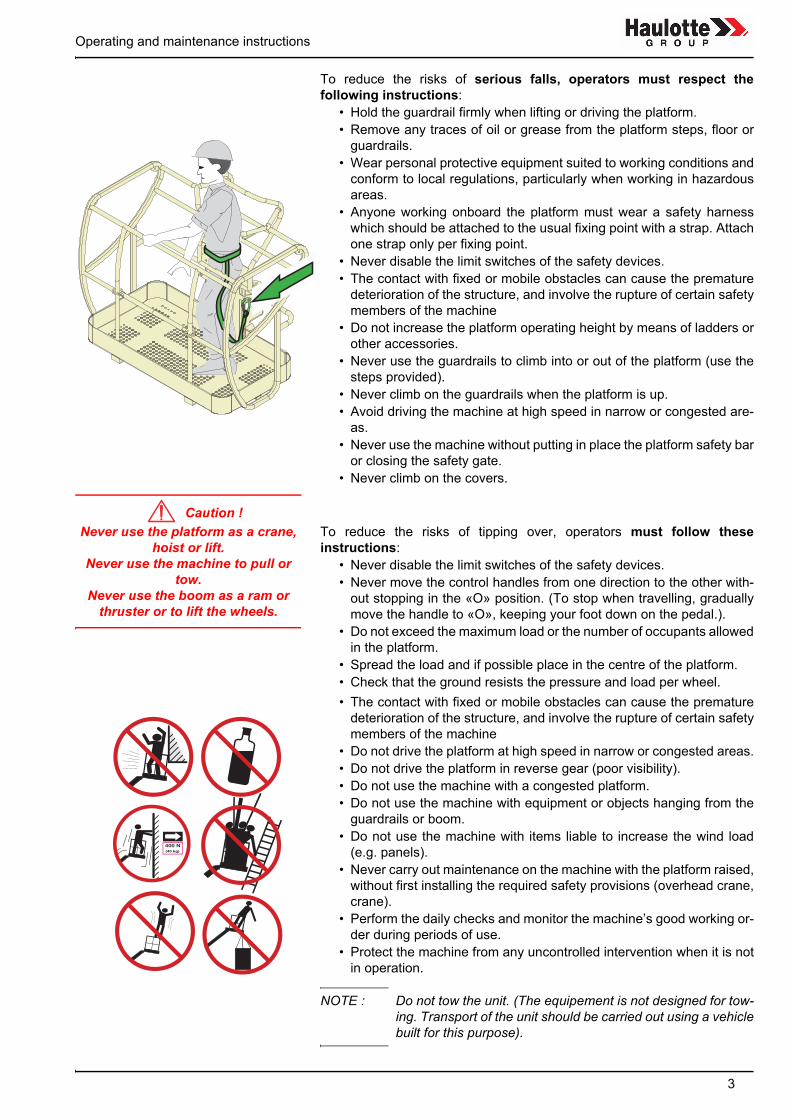
To reduce the risks of serious falls, operators must respect thefollowing instructions:
• Hold the guardrail firmly when lifting or driving the platform.• Remove any traces of oil or grease from the platform steps, floor or
guardrails.• Wear personal protective equipment suited to working conditions and
conform to local regulations, particularly when working in hazardousareas.
• Anyone working onboard the platform must wear a safety harnesswhich should be attached to the usual fixing point with a strap. Attachone strap only per fixing point.
• Never disable the limit switches of the safety devices.• The contact with fixed or mobile obstacles can cause the premature
deterioration of the structure, and involve the rupture of certain safetymembers of the machine
• Do not increase the platform operating height by means of ladders orother accessories.
• Never use the guardrails to climb into or out of the platform (use thesteps provided).
• Never climb on the guardrails when the platform is up.• Avoid driving the machine at high speed in narrow or congested are-
as.• Never use the machine without putting in place the platform safety bar
or closing the safety gate.• Never climb on the covers.
Never use the platform as a crane, hoist or lift.
Never use the machine to pull or tow.
Never use the boom as a ram or thruster or to lift the wheels.
To reduce the risks of tipping over, operators must follow theseinstructions:
• Never disable the limit switches of the safety devices.• Never move the control handles from one direction to the other with-
out stopping in the «O» position. (To stop when travelling, graduallymove the handle to «O», keeping your foot down on the pedal.).
• Do not exceed the maximum load or the number of occupants allowedin the platform.
• Spread the load and if possible place in the centre of the platform.• Check that the ground resists the pressure and load per wheel.• The contact with fixed or mobile obstacles can cause the premature
deterioration of the structure, and involve the rupture of certain safetymembers of the machine
• Do not drive the platform at high speed in narrow or congested areas.• Do not drive the platform in reverse gear (poor visibility).• Do not use the machine with a congested platform.• Do not use the machine with equipment or objects hanging from the
guardrails or boom.• Do not use the machine with items liable to increase the wind load
(e.g. panels).• Never carry out maintenance on the machine with the platform raised,
without first installing the required safety provisions (overhead crane,crane).
• Perform the daily checks and monitor the machine’s good working or-der during periods of use.
• Protect the machine from any uncontrolled intervention when it is notin operation.
NOTE : Do not tow the unit. (The equipement is not designed for tow-ing. Transport of the unit should be carried out using a vehiclebuilt for this purpose).

Operating and maintenance instructions
4
Caution !
Caution !
1.3 - RESIDUAL RISKS
1.3.1 - Risks of jerky movements and tipping over
The direction of travel can be reversed after a 180° turntable
rotation. Take account of the colour of the arrows on the chassis
compared with the direction of travel (green = forward, red =
reverse)Thus, moving the manipulator in the direction of the green arrow on the control panel will move the machine according to the direction indicated by the green arrow on the chassis. Similarly, moving a manipulator in
the direction of the red arrow on the control panel, will move the
machine in the direction of the red arrow on the chassis
Risks of jerky movement and tipping over are high in the followingsituations:
- Sudden action on the controls.- Overloading of the platform.- Uneven ground (Be careful during thaw periods in winter).- Gusts of wind.- Contact with an obstacle on the ground or at a height.- Working on platforms, pavements, etc.
Allow sufficient stopping distances: - 3 meters at high speed,- 1 meter at low speed.
Allow sufficient stopping distances: 3 metres at high speed and 1 metre atlow speed.Do not alter or override any components connected in any way to themachine’s safety or stability. Do not place or fasten a load so that it overhangs the machine’s parts.Do not touch adjacent structures with the elevator arm.
1.3.2 - Electrical risk
If the machine has a 220 V 16A max. plug, the extension must be connected to a mains socket
protected by a 30 mA differential circuit breaker.
Electrical risks are high in the following situations:- Contact with a live line (check safety distances before operation
near electricity lines) (see Chap 1.8, page 7).- Use during storms.
1.3.3 - Risk of explosion or burningThe risks of explosion or burning are high in the following situations:
- Working in explosive or inflammable atmosphere.- Filling the fuel tank near naked flames.- Contact with the hot parts of the motor.- Use of a machine causes hydraulic leakage.
1.3.4 - Risks of collision- Risk of crushing people in the machine operation zone (when
travelling or manoeuvring equipment).- The operator must assess the risks above him before using the
machine.- Pay attention to the position of the arms during turntable rotation.- Adapt movement speed to conditions related to the ground, traffic,
slope and movement of people, or any other factor that may causea collision.
- When driving down the ramp of a truck, ensure sufficient space isavailable for safe unloading.
- Check brake pad wear regularly to avoid all risk of collision. - Always use a winch line connected to the unit when loading and
unloading off tilt tray vehicules.

Operating and maintenance instructions
5
1.4 - INSPECTIONSComply with the national regulations in force in the country of machine use.For AUSTRALIA: ie.AS2550.10.For FRANCE: Order dated 1st March 2004 + circular DRT 93 dated 22September 1993 which specify:
1.4.1 - Periodic inspectionsThe machine must be inspected every 6 months in order to detect anydefects liable to cause an accident.These inspections are performed by an organisation or personnel speciallydesignated by the site manager and under his responsibility (whether or notthey belong to the company) Articles R 233-5 and R 233-11 of the FrenchLabour Code.The results of these inspections are recorded in a safety register kept bythe site manager and constantly available to the labour inspector and thesite safety committee (if one exists) and the list of specially designatedpersonnel (Article R 233-5 of the French Labour Code). Moreover, before each use, check the following:
• the operator’s manual is in the storage compartment on the platform,• the stickers are placed according to the section concerning «Labels
and their positions»,• oil level and any elements in the maintenance operation table • look out for any damaged, incorrectly installed, modified or missing
parts.
NOTE : This register can be obtained from trade organisations, and insome cases from the OPPBTP or private prevention agen-cies.
The designated persons must be experienced in risk prevention (Articles R233-11 or order n° 93-41).No member of personnel is allowed to perform any check whatsoeverduring machine operation (Article R 233-11 of the French Labour Code).
1.4.2 - Examination of machine suitabilityThe manager of the site where the machine is operated must ensure themachine is suitable, i.e. capable of performing the work in complete safety,and in compliance with the operating manual. Furthermore, the Frenchorder of 1st March 2004 addresses problems relative to leasing,examination of the state of conservation, checking upon operation afterrepairs, and test conditions (static test coefficient 1.25; dynamic testcoefficient 1.1). All users must consult this order’s requirements andcomply with them.
1.4.3 - State of conservationDetect any deterioration liable to cause hazardous situations (concerningsafety devices, load limiters, tilt sensor, cylinder leaks, deformation, welds,bolt tightness, hoses, electrical connections, tyre state, excessivemechanical gaps).
NOTE : If the machine is rented/leased, the user responsible for themachine must examine its state of conservation and suitabili-ty. He must obtain assurance from the leaser that general pe-riodic inspections and pre-operation inspections have beenperformed.

Operating and maintenance instructions
6
Caution !
1.5 - REPAIRS AND ADJUSTMENTSThese cover major repairs, and work on or adjustments to safety systemsor devices (of a mechanical, hydraulic or electrical nature).These must be performed by personnel from or working for PINGUELY-HAULOTTE who will use only original parts.Any modification not controlled by PINGUELY-HAULOTTE isunauthorised.The manufacturer cannot be held responsible if non-original parts are usedor if the work specified above is not performed by PINGUELY-HAULOTTE-approved personnel.
1.6 - VERIFICATIONS WHEN RETURNING TO SERVICETo be performed after:
• extensive disassembly-reassembly operation,• repair affecting the essential components of the machine,• any accident caused by the failure of an essential component.
It is necessary to perform a suitability examination, a state of conservationexamination, a static test, a dynamic test (see coefficient in paragraph (seeChap 1.4.2, page 5).
These test must be performed by a competent person.
1.7 - BEAUFORT SCALEThe Beaufort Scale of wind force is accepted internationally and is usedwhen communicating weather conditions. It consists of number 0 - 17, eachrepresenting a certain strength or velocity of wind at 10m (33 ft) aboveground level in the open.
Description of Wind Specifications for use on land MPH m/s0 Calm Calm; smoke rises vertically 0-1 0-0.21 Light Air Direction of wind shown by smoke 1-5 0.3-1.52 Light Breeze Wind felt on face; leaves rustle; ordinary vanes moved by
wind6-11 1.6-3.3
3 Gentle Breeze Leaves and small twigs in constant motion; wind extends light flag
12-19 3.4-5.4
4 Moderate Breeze Raises dust and loose paper; small Branches are moved 20-28 5.5-7.95 Fresh Breeze Small trees in leaf begin to sway; crested wavelets form
on inland waterways29-38 8.0-10.7
6 Strong Breeze Large branches in motion; whistling heard in telephone wires; umbrellas used with difficulty
39-49 10.8-13.8
7 Near Gale Whole trees in motion; inconvenience felt when walking against wind
50-61 13.9-17.1
8 Gale Breaks twigs off trees; generally impedes progress 62-74 17.2-20.79 Strong Gale Slight structural damage occurs (chimney pots and slates
removed)75-88 20.8-24.4

Operating and maintenance instructions
7
1.8 - MINIMAL DISTANCES OF SAFETY• It is important to hold the machine far away from the lines and equip-
ment of electrical current according to the applicable governmental ré-glements and the following diagram
Voltage distance minimum safety in meters
from 0 to 300 V Avoid contact
from 300 V to 50 kV 3.05
from 50 kV to 200 kV 4.60
from 200 kV to 350 kV 6.10
from 350 kV to 500 kV 7.62
from 500 kV to 750 kV 10.67
from 750 kV to 1000 kV 13.72

Operating and maintenance instructions
8

Operation and Maintenance - HA16PX / HA18PX
9
2 - PRESENTATION
The self-propelled elevating work platforms, models HA 16 PX and HA 18PX, are designed to carry out all kinds of overhead work within the limitsimposed by their characteristics (see Chap. 2.3, page 11, and Chap. 2.4,page 13) and provided that all safety instructions relating to the equipmentand environment of use are respected.The main control panel is situated in the platform.The control panel situated on the turntable is to be used in emergencies orcases of machine failure.
2.1 - IDENTIFICATIONA plate attached to the rear, right-hand side of the chassis, is engraved withall the necessary information for identification of the machine.
REMINDER:When requesting information, intervention or spare parts, youwill need to specify the machine type and serial number.

Operation and Maintenance - HA16PX / HA18PX
10
2.2 - MAIN COMPONENTS
11
3
7
4
16
1
26
13
15
14
5
8
9
10
12
1 - Rolling chassis 9 - Boom2 - Steering wheels 10 - Document holder3 - Drive and steering wheels 11 - Platform4 - Top control panel 12 - Turntable5 - Bottom control panel 13 - Counterweight6 - Anchoring lugs 14 - Right compartment 7 - Jib 15 - Left compartment 8 - Slew ring 16 - Arm

Operation and Maintenance - HA16PX / HA18PX
11
2.3 - WORKING AREA
2.3.1 - HA 16P working area
-70∞
+70∞

Operation and Maintenance - HA16PX / HA18PX
12
2.3.2 - HA 18P working area.
-70∞
+70∞

Operation and Maintenance - HA16PX / HA18PX
13
2.4 - TECHNICAL CHARACTERISTICS
2.4.1 - HA 16PX TECHNICAL CHARACTERISTICS DESCRIPTION HA 16PX Unit
Standard basket 1800x800
Basket option 2300x800
Load 230 230 KgMax. lateral manual force 400 400 NMax. wind speed 60 45 Km/hOverall platform length in idle position 6.95 mOverall platform length in transport position 5.25 mHeight under basket floor in idle position 0.235 mHeight under basket floor in work position mOverall width of the platform 2.3 (standard tyres) 2.38 (wide tyres) mOverall height of the platform 2.2 mFloor clearance, chassis edge 0.4 mFloor clearance of the basket in the idle posi-tion 0.235 m
Floor clearance of the basket in the transport position m
Platform height in the transport position 2.15 mPlatform height in the idle position 2.20 mPlatform width at tyre level 2.3 (standard tyres) 2.38 (wide tyres) mMax. height of floor rise 14 mMax. height of floor lowering mMax. height of articulation point 6.60 mMax. reach of the basket above the ground 8.70 mTurntable rotation angle 360 (continuous) °Positive boom range 74 °Negative boom range -3 °Overall length of the basket 1.80 2.3 mOverall width of the basket 0.80 0.8 mOverall height of the basket, platform 1.10 mBasket rotation angle -90° /+ 90° °External turning radius 4 mInternal turning radius 1.9 mTyre width 0.385 mLateral distance between the wheels 2.00 mTyre diameter 1.080 mMax. slope in travel 50 %Authorised tilt 5 °Hydraulic tank 100 lFuel tank 72 lTotal weight 7240 KgDifferential blocking yesHydraulic brakes 2Freewheel yes DEUTZ motor- Power- Power at slow speed - Consumption
F3L1011F38CH/28.33hp/28Kw at 2400 rpm
20.4 CH/15.21 hp/15Kw at 1250 rpm2309 Kwh

Operation and Maintenance - HA16PX / HA18PX
14
2.4.2 - HA 18PX TECHNICAL CHARACTERISTICS
Travel speed - micro speed:- low speed:- medium speed:- high speed:
0.220.380.771.52
m/s
Hydraulic pressure - general- travel - steering - orientation
24242410
MPa
Max. force on one wheel 3610 KgMax. pressure on the ground - hard ground (concrete)- soft ground (earth)
83.2
daN/cm²
Starter battery 12V-95Ah-450ASupply voltage 12 VAccoustic power 104 dB(A)Accoustic pressure at 10 metres 75 dB(A)
DESCRIPTION HA 16PX Unit
DESCRIPTION HA 16PX UnitStandard basket
1800x800Basket option
2300x800Load 230 230 KgMax. lateral manual force 400 400 NMax. wind speed 60 45 Km/hOverall platform length in idle position 7.60 mOverall platform length in transport position 5.90 mHeight under basket floor in idle position 0.235 mHeight under basket floor in work position mOverall width of the platform 2.3 (standard tyres) 2.38 (wide tyres) mOverall height of the platform 2.2 mFloor clearance, chassis edge 0.4 mFloor clearance of the basket in the idle posi-tion 0.235 m
Floor clearance of the basket in the transport position m
Platform height in the transport position 2.15 mPlatform height in the idle position 2.20 mPlatform width at tyre level 2.3 (standard tyres) 2.38 (wide tyres) mMax. height of floor rise 15.3 mMax. height of floor lowering mMax. height of articulation point 6.60 mMax. reach of the basket above the ground 10.07 mTurntable rotation angle 360 (continuous) °Positive boom range 74 °Negative boom range -3 °Overall length of the basket 1.80 2.3 mOverall width of the basket 0.80 0.8 mOverall height of the basket, platform 1.10 mBasket rotation angle -90° /+ 90° °

Operation and Maintenance - HA16PX / HA18PX
15
External turning radius 4 mInternal turning radius 1.9 mTyre width 0.385 mLateral distance between the wheels 2.00 mTyre diameter 1.080 mMax. slope in travel 50 %Authorised tilt 5 °Hydraulic tank 100 lFuel tank 72 lTotal weight 8120 KgDifferential blocking yesHydraulic brakes 2Freewheel yes DEUTZ motor- Power- Power at slow speed - Consumption
F3L1011F38CH/28.33hp/28Kw at 2400 rpm
20.4 CH/15.21 hp/15Kw at 1250 rpm2309 Kwh
Travel speed - micro speed:- low speed:- medium speed:- high speed:
0.220.380.771.52
m/s
Hydraulic pressure - general- travel - steering - orientation
24242410
MPa
Max. force on one wheel 3960 KgMax. pressure on the ground - hard ground (concrete)- soft ground (earth)
8.23.6
daN/cm²
Starter battery 12V-95Ah-450ASupply voltage 12 VAccoustic power 104 dB(A)Accoustic pressure at 10 metres 75 dB(A)
DESCRIPTION HA 16PX Unit

Operation and Maintenance - HA16PX / HA18PX
16
2.5 - DIMENSIONS
2.5.1 - HA 16PX dimensions
2000 mm - 6ft 6in
2200 mm
- 7ft 2in
6950 mm - 22ft 9in
2300 mm - 7
ft 6in
(2380 mm - 7
ft 9in)

Operation and Maintenance - HA16PX / HA18PX
17
2.5.2 - HA 18PX dimensions
2000 mm - 6ft 6in
2200 mm
- 7ft 2in
7600 - 24ft 11in
2300 mm - 7
ft 6in
(2380 mm - 7
ft 9in)

Operation and Maintenance - HA16PX / HA18PX
18
2.6 - LABELLING
2.6.1 - Position of labels
Ref Code Qty Description
2 307P218190307P218220
11
HA16PX logo HA18PX logo
5 30781437103078143690
22
Floor height + load (HA18P/PX)Floor height + load (HA16P/PX)
7
30781434203078143430307814344030781434503078143460307814347030781449403078143540307814583030781459403078144560
1
Operating instructions (French)Operating instructions (Spanish)Operating instructions (German)Operating instructions (English)Operating instructions (Italian)Operating instructions (Dutch)Operating instructions (Danish)Operating instructions (Finnish)Operating instructions (Portuguese)Operating instructions (SwedishOperating instructions (Australia)
8
307P218070307P218110307P218090307P218080307P218100307P218120307P218130307P218160307P218150307P218140
1
Manufacturer’s plate (French)Manufacturer’s plate (Spanish)Manufacturer’s plate (German)Manufacturer’s plate (English)Manufacturer’s plate (Italian)Manufacturer’s plate (Dutch)Manufacturer’s plate (Danish)Manufacturer’s plate (Finnish)Manufacturer’s plate (SwedishManufacturer’s plate (Portuguese)
9 3078173550 1 Do not stop in the work area
10 30781434903078144430 1 Machine uninsulated
Danger of electrocution (Australia)11 3078143520 1 "Hydraulic oil" label 12 3078145070 1 Travel direction danger13 3078143590 1 High and low hydraulic oil 14 3078143620 2 Risk of hand crushing 15 3078143510 1 Battery check plate 16 3078143610 1 Wear protective gear 17 3078143640 2 Do not stand on the cover 19 3078143600 1 Caution: do not use as a welding earth
20 3078143540a3078144570 1 The part must be connected
The part must be connected (Australia)21 3078143680 b 1 Read CE user manual 23 307P217920 1 Chassis control panel 24 307P217930 1 Platform control panel 26 3078143560 1 Do not use the machine during charging 29 3078145730 1 240V socket position (Holland)30 2420505950 1 Guarantee activation31 3078145180 1 Do not interchange33 3078144490 4 Handling lugs (Australia)34 3078144510 1 Fuel filling with gun only (Australia)35 3078144390 1 Charger connection (Australia)40 2421808660 Yellow and black reflective adhesive marking (Holland)41 3078143570 1 ring lubrication 42 3078143530 2 Remove the pin

Operation and Maintenance - HA16PX / HA18PX
19
43178B153230178B153240178B153140
1 "E" logo "N" logo X logo
44 3078143630 2 Risk of body crushing
45178C143900178C143910178C143920
1 "X" logo "E" logo "N" logo
46 307P218310 1 hand pump plate3078146150 1 Z1 - Z2 - Z3
48 3078137440 a 1 Green arrow49 3078137430 a 1 Red arrow50 307P217770 3 "HAULOTTE" logo52 3078144930 a 1 Emergency operation (Australia)53 3078144520 1 Wear harness (Australia)54 3078148700 1 Acoustic power58 307P216290 2 Fixing point of harness.60 7815351 1 Safety
100 30781515303078151540
44 Load for wheel
Ref Code Qty Description

Operation and Maintenance - HA16PX / HA18PX
20
23
719
5 17
42
14
9
50
44
30
48
49
8 54
100
41
51
44
14
50
951
17
2
50
21
58
60
10
24
512
20
47
51
19
31
46
13
11
27
28
29
53
40
40
100
55
57
Holla
nde
Aust
ralia
33
33
34
35
52
P2
01
25
b

Operation and Maintenance - HA16PX / HA18PX
21
2.6.2 - Common labels
a
9 14 44 11
13
20
21
42 41
1917
7
60

Operation and Maintenance - HA16PX / HA18PX
22
.F
.GB
.D
7814 518
Composant spÈcifique ‡ cette machine.
NE PAS INTERCHANGER.
Component specificto this machine.
DO NOT INTERCHANGE.
Komponenten nur f¸rdiese maschine geeignet. BITTE AUF EINE ANDERE
MASCHINE NIGHT MONTIEREN.
N∞ MACHINE - MASCHINE N∞
7813 743 a7813 744 a
10 31 12
23
24
48 49
46
58
54

Operation and Maintenance - HA16PX / HA18PX
23
2.6.3 - Labels specific to models
2.6.4 - Labels specific to optionsBi-energy option
HA 16PX HA 18PX
5 5
100 100
+
26 15 16

Operation and Maintenance - HA16PX / HA18PX
24
2.6.5 - Labels specific to Holland
2.6.6 - Labels specific to Australia
7814 573 a
29
20 33
34
a
35
52
53

Operation and Maintenance - HA16PX / HA18PX
25
Caution!
3 - OPERATING PRINCIPLE
3.1 - HYDRAULIC CIRCUITAll the machine’s movements are powered by hydraulic energy from a self-regulatiung, open circuit, piston pump, equipped with a "LOAD SENSING"compensator.
3.1.1 - Movement control
3.1.1.1 -Travel, slewing, arm lifting and boom lifting movements These movements are controlled in proportional distribution (compensatedin pressure). Pump flow is automatically adapted to the demand by the"LOAD SENSING" channel. In neutral, there is no pump flow.
3.1.1.2 -Telescoping, jib, basket rotation, compensation and steering movements These movements are controlled by 4-channel electrovalves, with on/offflow. A proportional distributor valve provides the flow required for thesemovements.
3.1.1.3 -Telescoping, boom lifting, arm lifting and jib cylinders These are equipped with sealed, flanged, balancing valves.
3.1.2 - ActuatorsThe type of actuator varies depending on the movement.
Adjustments can only be made by specialised personnel.
3.1.2.1 -Platform rotationPlatform rotation uses a hydraulic motor. Rotation speed can be adjustedby flow limiters.
3.1.2.2 -Platform compensationCompensation works by oil transfer between 2 cylinders with similarcharacteristics.The cylinder being compensated is fitted with a double flanged controlledvalve.
3.1.2.3 -Travel (moving the machine)Hydraulic motors mounted in the wheels drive the wheels via epicycloidalreducing gears. The motors are mounted on the four steering wheels.The motor pressure supply eliminates the brake’s action on the wheels. Assoon as movement stops, the brake returns to its place by spring action. A hydraulic differential blocking system is provided on each axle.The three speeds (high, medium and low) are controlled by a switch.
Speed 4x4 version principleHigh speed The steering axle is switched to freewhel and the flow from the pump goes through
the motors mounted in series on the front wheels.Medium speed The steering axle is switched to freewhel and the flow from the pump goes through
the two motors mounted in parallel on the front wheels.Low speed Pump flow is divided between the front and rear axles. The flow to each axle
supplies the axle’s hydraulic motors mounted in parallel.

Operation and Maintenance - HA16PX / HA18PX
26
Caution!
Caution!
3.1.3 - Manual emergency system If the diesel motor works, but a failure occurs preventing use of arm lifting,boom lifting, turntable orientation, jib, basket rotation, compensationmovements from the platform and turntable control panels, thesemovements can be controlled using the mechanical levers and pushing themanual control of the electrovalve located at the top on the maindistribution block.
3.1.4 - Emergency and rescue
Only a skilled operator can perform emergency or rescue operations.
3.1.4.1 -RescueIf the operator in the platform becomes unable to control the movementsinspite of the machine working normally, a skilled operator on the groundcan use the turntable control panel with the main diesel power source tobring the platform operator back down to the ground.
3.1.4.2 -Emergency operation
Use of the emergency unit is exclusively reserved for rescuing personnel if the main hydraulic
power supply fails. Any other use may cause damage
A standby electropump unit controlled from either the platform or theturntable can be used if the main pump fails. If an operating incident occurs preventing the operator in the platform toreturn to the ground, a skilled operator can bring him down using theelectric pump and the electric controls on the turntable control panel. Instructions:
• Turn the key to the "turntable station" position (Ref 13 , Photo :, page33)
• Activate the switch (Ref 9, Photo :, page 33) controlling the standbyunit.
• Activate the switches corresponding to the movements required (Ref5-6-7-8, Photo :, page 33).
3.2 - ELECTRICAL CIRCUITThe electrical power used for the controls and to start the heat motor is supplied by a 12v battery.
3.2.1 - Control of the load in the platformIf the load in the platform exceeds the maximum authorised load, nomovements are possible from the platform control station. The overloadlight indicator on the platform panel and the buzzer alert the operator. Loadmust be removed to reset the assembly.
3.2.2 - Tilt checkThe fault light indicator on the platform control panel flashes and the tiltsensor emits an audible signal when maximum permitted tilt is reached . Ifthe situation persists, after a delay of 1 to 2 sec., the controls for lifting theboom (up), lifting the arms (up), telescope out, are cut off together with thetravel movement as long as the machine is extended.To restore the travel movements, all lifting parts of the machine must becompletely lowered.
NB: While the machine is extended, the tilt detector issues anaudible signal as long as the slope remains greater than theauthorised limit, indicating to the operator that the platformcannot be extended

Operation and Maintenance - HA16PX / HA18PX
27
3.2.3 - High travel speed High travel speed is only authorised when the platform is completelyfolded. When the boom is lifted or the arms extended, only low speed is possible.
3.2.4 - Hour counterThe operating time of the heat motor is recorded by an hour counter.

Operation and Maintenance - HA16PX / HA18PX
28

Operation and Maintenance - HA16PX / HA18PX
29
Caution!
4 - OPERATION
4.1 - OPERATING SAFETY MECHANISMSTo prevent the machine from being used in excess of its capabilities, safetymechanisms have been integrated to protect personnel and the machine.These mechanisms immobilise the machine or disable movements.In either case, if knowledge of the characteristics and operation of themachine is insufficient, a machine failure may be diagnosed, when in factthe safety mechanisms are operating correctly.It is therefore necessary to fully understand the instructions in the followingchapters.
Do not make any movements before studying the instructions Chap. 4.3,
page 33.
4.1.1 - Travel (controlled from "platform" station)To move the machine, activate the "fail-safe" by holding down themanipulator button. Releasing the "fail-safe" pedal stops the travel movement. Travel is possible up to a maximum slope of 5° (approx. 9%).
CAUTION: At high and medium speed (4x4 model), it is not possible to raise theboom or to carry out telescoping and rotation movements.
THE COMPENSATION COMMAND IS ACTIVE BELOW A THRESHOLDOF 8.2 FT ONLY
4.1.2 - Emergency or rescue procedure
CAUTION:If a rescue or emergency manual procedure is necessary, the safetymechanisms are neutralised and only qualified operators can carryout the required operations.

Operation and Maintenance - HA16PX / HA18PX
30
Caution!
Caution!
Caution!
4.2 - UNLOADING - LOADING - MOVING THE MACHINE - PRECAUTIONS
When transporting the machine, it is vital to block the turntable using the rotation locking pin located under
the turntable (Photo 6, page 36)
IMPORTANT: Before moving or using the machine check it over tomake sure it has not been damaged during transport. If any damageis apparent, express your reservations in writing to the transporter.
A mistake could cause the machine to fall, potentially causing very serious injuries and material
damage.
Unload the machine on a stable, flat and sufficiently resistant surface (seeground pressure - Chap. 2.4, page 13), free of any obstacles.
4.2.1 - Unloading by lifting• Use a lifting beam with 4 slings. • Take the following precautions:
- the lifting equipment is in good condition and of sufficient capacity,- the slinging accessories can bear the load and show no signs of
abnormal wear,- the slinging lugs are clean and in good condition,- the personnel is qualified to use lifting equipment.
• Unloading:- hook the 4 slings to the 4 slinging lugs,- lift slowly, ensuring the load is evenly distributed and slowly put the
machine down.
Never stand underneath or too close to the machine during
operation.

Operation and Maintenance - HA16PX / HA18PX
31
4.2.2 - Unloading using rampsPrecautions: ensure that the ramps can bear the load and that the surfaceoffers sufficient grip to avoid any risk of the machine slipping during theprocedure. Make sure the ramps are firmly secured in position.
NB: This method requires the machine to be in operation (seeChap. 4.4, page 36), therefore, to avoid all risk of incorrectoperation, select low travel speed.
NB: The slope of the ramp is nearly always greater than the maxi-mum authorised working tilt (5°). Therefore, the boom andarms must be lowered or travel will be impossible.
In this case, the buzzer sounds but travel movement is possible.If the slope is greater than the maximum authorised tilt during travel, use awinch to add traction (see Chap. 2.4, page 13).
4.2.3 - LoadingThe same precautions must be taken as for unloading.The machine must be secured as shown in the diagram below.Select high speed to mount lorry ramps.
4.2.4 - Moving the machineClosely follow traffic rules or instructions for the area in which the machineis to be moved:
• If moving over rough terrain, inspect the route carefully before begin-ning overhead work.
• When moving the machine, always keep a sufficient distance awayfrom unstable areas or banks.
• Ensure that nobody is standing too close to the machine beforecarrying out any movement of the whole machine or the elevatingparts.

Operation and Maintenance - HA16PX / HA18PX
32
REMINDER: the machine may not be driven on public highways.
4.2.5 - Filling the fuel tank• Before filling, ensure that the fuel is the type recommended and that
it is stored in clean conditions with no risk of being polluted.• Do not take fuel from a barrel without decanting and never use fuel
from the bottom.Due to the risk of fire, take the following precautions when filling the tank:
• do not smoke• stop the heat motor if it is operating• stand with the wind behind you to avoid being sprayed with fuel• touch the outside of the filling hole with the pump nozzle before star-
ting to fill with fuel to avoid the risk of sparks due to static electricity.• close the tank cap tightly and clean up any fuel that has spilled out of
the tank.

Operation and Maintenance - HA16PX / HA18PX
33
Caution!
4.3 - OPERATIONS PRIOR TO FIRST USE OF THE MACHINE
REMINDER:Before carrying out any operation, ensure that you are familiarwith the machine by reading this manual and the instructionson the various plates.
4.3.1 - "Turntable" control panelPhoto 1Photo 2
During high pressure cleaning, do not aim the jet directly towards the electrical boxes and cabinets.
18
19
1
2
1 2 3 4
7
56
8
917
11
13
1415
16
12
20
1 - Motor oil pressure light 2 - Motor temperature light3 - Battery charge indicator4 - Filter clogging indicator5 - Boom telescope control 6 - Raising control7 - Jib control 8 - Lifting control9 - Turntable rotation control
11 - Turntable / platform control panel selector12 - Emergency stop button13 - Motor acceleration control 14 - Motor start button15 - Emergency control 16 - Hour counter17 - Optional flashing light control18 - Buzzer 19 - Tilt detector 20- Compensation switch

Operation and Maintenance - HA16PX / HA18PX
34
4.3.2 - "Platform" control panelPhoto 3 and 4
NB: The manipulators are equipped with a "fail-safe" safety con-tact.
4.3.3 - Checks before using the machine
• Ensure that the ground under the machine is flat, stable and can bearthe weight of the machine (see Chap. 2.4, page 13 - ground pressu-re)
NB: See WORKING AREA diagram (Chap. 2.3, page 11) for maxi-mum authorised tilt.
• Ensure that no obstacles can obstruct machine movements:- travel (movement of the whole machine).- turntable rotation- telescoping and lifting: see the WORKING AREA diagram (Chap.
2.3, page 11). • Carry out a visual inspection of the machine: pay particular attention
to flaking paint or acid leaking from the battery. • Check that all bolts, screws, connections and hoses fit tightly, that the-
re are no oil leaks, and that no electrical connections have becomedamaged or disconnected.
• Check the arms, boom, jib and platform: there should be no visible da-mage, no traces of wear or deformation.
1 2 3
7
8 9 10 12 1314
45
615
16
17
3 4
18
11
1- Orientation and boom lifting manipulator 2- Arm lifting manipulator 3- Travel and BACK steering manipulator 4- Power light indicator 5- Starter switch 6- Horn 7- Low, medium, high selector switch 8- FRONT steering switch 9- Differential blocking switch
10- Jib switch 11- Platform rotation switch 12- Telescope switch 13- Compensation switch14- Emergency stop button 15- Fault light indicator 16- Backup pump 17- 220 V single phase - 16 A plug18- Platform overload indicator

Operation and Maintenance - HA16PX / HA18PX
35
Caution!
Caution!
Caution!
• Check that there are no leaks, traces of wear, blows or scratches, rustor foreign bodies on the cylinder rods.
• Check that there are no leaks from the wheel reducing gears.• Pump and hydraulic unit: no leaks, all components tight.• Check that the reducing gears have not become disconnected.• Check the tightness of the wheel nuts and the extent of tyre wear.• Check that the battery terminals are clean and tight: if they become
loose or corroded, power may be lost.• Check the electrolyte level in the batteries: the level should be ap-
proximately 10 mm above the plates; add distilled water if necessary.
Follow the safety instructions supplied by the battery manufacturer
• Check that the main control panel power cable is in good condition.• Check that the emergency stops work correctly.
This type of machine is not insulated and must not be used close to
electricity lines.
• Check that the air filter is clean - see motor manual.• Check levels of:
- motor oil: gauge (Ref.1 Photo 4, page 35), top up if necessary(see motor manual).
- hydraulic oil (boom Photo 5, page 35) top up if necessary by fillingvia the cap (1). (see Chap. 5.3.3.1, page 46).
- diesel level: the min. and max. levels can be checked when thecover is closed, using the two light indicators. Top up if necessary(cap Ref.2 Photo 5, page 35).
To top up fluid levels, use only the products recommended in the
consumables chapter.
• Check the hydraulic filter clogging indicator (Ref. 2 Photo 4, page 35).If the red indicator is visible, replace the filter cartridge ref. 3 (seeChap. 5.3.3, page 46).
• Check that the tilt detector (Ref.19 Photo 2, page 33) is working cor-rectly by angling the support plate. Beyond an angle of 5°, an alarmshould sound.
Photo 4
Photo 5
54
2
1
1
3
2

Operation and Maintenance - HA16PX / HA18PX
36
Caution!
Caution!
• Turntable locking pin:- Ensure that the locking pin (Ref. 1 Photo 6, page 36) for turntable
rotation is removed.
When transporting the machine, it is vital to block the turntable using the
rotation locking pin situated under the turntable (Photo 6, page 36)
Photo 6c
4.4 - STARTING WORKIMPORTANT: WORK MAY ONLY BEGIN WHEN ALL OF THEINSTRUCTIONS GIVEN IN THE PREVIOUS SECTION HAVE BEENFOLLOWED SCRUPULOUSLY.TO BECOME FAMILIAR WITH THE MACHINE CARRY OUT THEFIRST FEW OPERATIONS AT GROUND LEVEL, KEEPING THEMACHINE IN ITS TRANSPORT CONFIGURATION: COUNTER-WEIGHT FORWARD, BOOM LOWERED.
When the counterweight is placed above the steering wheels, the
travel and steering controls act in the opposite directions.
REMINDER:The main control panel is on the platform.
In normal operating conditions, the "turntable" control panel is anemergency or rescue control station, and only used if absolutelynecessary.
4.4.1 - Operations from the groundOnly the heat motor version of the machine can be used from this controlstation.Motor starting: (Photo 1, page 33)
• Ensure that the emergency stop button (Ref 16) is pulled out.• Put the operating station selection key switch (Ref 15) in the "ground
control" position (pictograms). In this position, the "platform" panelcontrols are cancelled.
• Motor oil pressure (Ref 1) and battery charge (Ref 3) light indicatorsare on. The air filter clogging light indicator (Ref 4) is off.
• Press the start button (Ref 14), the motor starts, the light indicators(Ref 1 and 3) go out.
NB: If the motor does not start, switch off the ignition by pressingthe emergency stop button and start the operation over again.
6
1

Operation and Maintenance - HA16PX / HA18PX
37
Caution!
Caution!
• Leave the motor to warm up and in the meantime check that the hourcounter (Ref 12), motor and pump are working correctly.
Testing the various movements (Photo 1, page 33)
REMINDER:Always make sure that no obstacles can cause an obstructionbefore any operation.
• Test the lifting movement in the up and then down direction (controlRef.8).
• Test the raising movement in the up then down direction (controlRef.6 )
• Stop boom lowering in the horizontal position.• Then test the turntable rotation movements in both directions (control
Ref.9) and telescoping in/out (control Ref. 5) then lower the boomcompletely.
• Switch to "platform" control.• Put the key selector (Ref.15 Photo 1, page 33) in the "platform" posi-
tion (green rectangle).• Check that the tilt detector works properly (Ref.19 Photo 2, page 33).
THE COMPENSATION COMMAND IS ACTIVE BELOW A THRESHOLDOF 8.2 FT ONLY
4.4.2 - Operations from the platform (Photo 3, page 34)• Climb into the basket, respecting the maximum load instructions. If
necessary, distribute the load evenly over the whole platform.
MAXIMUM LOAD: 230 KG. NB: If the load in the platform exceeds the maximum authorisedload, no movements are possible from the platform controlstation. The overload light indicator on the platform panel andthe buzzer alert the operator. Load must be removed to re-en-able the machine. There is no load restriction on the reach.
Control station test• Before any operation, ensure that the green light indicator (Ref. 4) is
on, indicating that machine power is on and that the selector is in the"platform" position
• Check that the emergency stop button (Ref.14) is unlocked.• Check that the horn works.
High speed is only availble if the machine is folded. Even if only
slightly extended, only micro speed is available.
Work may now begin.
Testing the movements• To make a movement, choose the corresponding manipulator or se-
lector.• Press the "fail-safe" contact and activate the required manipulator.• The speed and angle of tilt of the manipulators enable gradual mvoe-
ment.• If the ground is not horizontal, correct the platform position using the
corresponding selector.• Test telescoping, jib, basket rotation movements with the relevant se-
lector.• Test the rear axle steering movement using the selector placed on the
handle of the travel manipulator. Test front axle steering movementusing the selector on the platform control panel.

Operation and Maintenance - HA16PX / HA18PX
38
Caution!
• Test the 2 travel speeds (in 4x2x4 version) or the 3 speeds (in 4x4x4version) by activating the low or high speed selector in 4x2x4 versionor the low, medium or high speed selector in 4x4x4 version.
• Movement direction is indicated by the blue arrows.
4.5 - BUILT-IN GENERATOR (OPTION)
Do not expose the built-in generator to direct contact with a jet of water or a high pressure cleaner.
(See photo Built-in generator and socket in the basketr, page 38)The built-in generator enables voltage supply (220V or 110V depending onthe option chosen) in the platform to enable connection of a tool, withmaximum power 3 KW.
Photo 7:Built-in generator and socket in the basketr
4.5.0.1 -Instructions:
• Switching on the built-in generator:
- Activate the circuit breaker (Ref 2 , Photo :Built-in generator andsocket in the basketr, page 38)
- Put the selector is in the "platform" position (green circle)- Put the button above the power socket in the ON position and the
button's green light indicator comes on (Ref. 1, See photo Built-ingenerator and socket in the basketr, page 38).
- Connect the tool to the socket.- At any time, you can change the tool.
NOTA: When using the built-in generator, you cannot make any ma-chine movements. To make a movement, you must switch offthe built-in generator (see instructions below).
• Switching off the built-in generator:
- Disconnect the tool from the socket.- Put the button above the power socket in the OFF position and the
green light indicator goes out (Ref. 1, See photo Built-in generatorand socket in the basketr, page 38).
- Movement is active once again, you can make any movements.
1
2

Operation and Maintenance - HA16PX / HA18PX
39
Caution!Use of the emergency unit is
exclusively reserved for rescuing personnel if the main hydraulic
power supply fails. Any other use may cause damage
4.6 - EMERGENCY OPERATION WITH THE STANDBY ELECTROPUMP UNIT Photo 8:Emergency control
Movements can be controlled when the main energy source malfunctions.There is an electropump unit powered by the starter battery. This unit canbe controlled from either the turntable control panel or the platform controlpanel.The emergency standby electropump control operates in the same wayfrom both control panels.
• Instructions:- Select the control panel you want to validated (orange or green),
(Ref 1, Photo :Emergency control, page 39)- Activate and hold down the emergency control switch (Ref 2,
Photo :Emergency control, page 39)- Actvate and hold down the switch corresponding to the
movements required (Ref 3, Photo :Emergency control, page 39).
4.7 - RESCUE OPERATIONIf the machine is working normally, but the operator in the platformbecomes unable to return the platform to the ground, an operator at groundlevel may do so:
• Switch the selection key (ref. 13 , Photo :, page 33) to the "turntable"position.
• Control the movements required using the controls corresponding tonormal operation.
1
2
3

Operation and Maintenance - HA16PX / HA18PX
40
Caution!
Caution!
Caution!
Caution!
Caution!
4.7 - UNCOUPLINGIt is possible to uncouple the reducing gears on the drive wheels to be ableto tow the machine if it breaks down.
In this configuration, the machine is no longer braked.
Uncoupling procedure:• Unscrew the 2 screws with a 11 wrench (Photo 14, page 40).
To tow the machine, it is essential to use a rigid bar and not to exceed
5 kph.
Photo 14
• Turn over the part and screw up again. The reducer is on free wheel(Photo 15, page 40).
Photo 15
The coupling of gear motors must be carried out by competent
operators.
Coupling procedure:Proceed in the opposite order from the uncoupling procedure.
This operation is to be carried out on even ground.
NOTA : Handling is facilitated when it is carried out with 2 people
As long as the 4 gear clutches are not in place, the machine does not
slow down properly.

Operation and Maintenance - HA16PX / HA18PX
41
5 - MAINTENANCE
5.1 - GENERAL RECOMMENDATIONS The maintenance operations described in this manual apply when themachineis used in ordinary conditions.Under difficult conditions: extreme temperatures, high humidity, a pollutedatmosphere, high altitude, etc., some of these operations should be carriedout more frequently and special precautions should be taken. For more details check the motor manufacturer's manual and consult yourlocal PINGUELY-HAULOTTE agent.Only qualified and competent personnel may carry out interventions on themachine and safety instructions relating to personnel and environmentprotection must be respected.As far as the motor is concerned, refer to the manufacturer's manual andinstructions.
Regularly check proper operation of the safety mechanisms:• Tilt detector: buzzer + stop (travel, boom lifting, arm lifting and teles-
cope out movements disabled).• Platform overload : The overload system is set so that it trips before
120% permitted load.• High speed unavailable (or medium speed for the 4x4 model) if the
boom is raised, arm is lifted, telescope is out.
CAUTION:• Do not use the machine as a welding earth. • Do not weld without disconnecting the (+) and (-) terminals of the
batteries. • Do not use to jumpstart other vehicles.

Operation and Maintenance - HA16PX / HA18PX
42
5.2 - MAINTENANCE PLAN The plan (following page) shows the frequency and area of maintenanceand the consumables to be used.The reference shown in the symbol shows the area maintained based onthe frequency.The symbol represents the consumable to use (or the operation to becarried out).
Consumable Specification Symbol Lubricants used by Pinguely-Haulotte
ELF TOTAL
Motor oil SAE 15W40 SHELL / RIMULA
Gearbox oil SAE 90 ESSO EP 80 W 90
TranselfEP 80 W 90 TM 80 W/90
Hydraulic oil AFNOR 48602ISO VG 46
BP SHF ZS 46
HYDRELFDS 46
EQUIVISZS 46
Optional bio-degrada-ble hydraulic oil Bio ISO 46
Lithium grease KP 2 K ESSOBeacon EP2 Epaxa 2
Lithium grease NLGI 2 EP ESSO MolyMulti-Purpose Grease
Cadrexa GR1 AL
Lead-free grease Grade 2 or 3 ESSOGP GREASE Multimotive 2 Multis
EP 2
Exchange or specific operation

Operation and Maintenance - HA16PX / HA18PX
43
HOURS
50
50028
19 11 12
1 000
2 000
10
50
250
500
10
7
17
23
1818
25
5
16
25
9
4
14
9
6
24
31
22
1
10
50
250
500
1 000
2 000
20
1816 9
25
10
15
12
2
189
29
4 8 3
28
13
30
27
14
25

Operation and Maintenance - HA16PX / HA18PX
44
5.3 - OPERATIONS
5.3.1 - Summary table
FREQUENCY OPERATIONS REF
Every day or before each use
• Check the levels:- motor oil- hydraulic oil- diesel
• Check cleanliness:- diesel pre-filter, replace if water or impurities are found- motor air filter- machine (particularly check the tightness of connectors and
hoses), also check the condition of tyres, cables and allaccessories and equipment.
• Check hydraulic oil filter clogging. If the clogging indicator is vi-sible, change the cartridge.
123
856
7
Every 50 hours
Motor: see manufacturer’s manual• Grease:
- wheel pivot axles: 2 x 2 points- turntable rotation locking pin
• Check the diesel pre-filter, replace if water or impurities arefound
• Check the level of the drive wheel reducing gears (see Chap.5.3.3.2, page 46)
CAUTION: after the first 50 hours: • Change the hydraulic filter cartridge
(see 250 hour freqeuncy)• Empty the drive wheel reducers
(see 500 hour frequency)- 2 points for the 4x2 model - 4 points for the 4x4 model
• Check the tightness:- of slew ring screws (torque 21,5 daNm)- of wheel nuts (torque 32 daNm)
22
1011169
17
18
1912
Every 250 hours
Motor: see manufacturer’s manual• Change the hydraulic filter cartridge• Grease:
- bearings of the steering wheels 4x2 (remove the cap)- slew ring bearing path (rotate during the operation) 2 points- friction parts of the telescope (spatula)- teeth of the slew ring (using a brush)
• Check condition of rings (condition and positioning) and ex-change them if damaged or broken.
• Check 'wear and tear' indicator of the telescope feet; to be re-placed if indicator not visible.
2423
14132015
Every 500 hours
Motor: see manufacturer’s manual• Empty wheel reducing gears• Refill with oil: capacity 2 x 0.7 l for the 4x2 - 4 x 0.7 l for the 4x4• Ring screws: check tightness and tighten if necessary
2528
Every 1000 hours or every year
Motor: see manufacturer’s manual • Empty: hydraulic oil tank 27
Every 2000 hours
Motor: see manufacturer’s manual• Empty: hydraulic oil tank and whole circuit
• Empty and clean the diesel tank • Grease: rotation reducing gear: 1 point
31282930
Every 3000 hours or every 4 years
• Check:- the state of telescoping friction pads- the state of electric cables, hydraulic hoses, etc

Operation and Maintenance - HA16PX / HA18PX
45
REMINDER:The above frequencies should be reduced if work is carriedout in difficult conditions (consult After Sales Service ifnecessary).
5.3.2 - Tightening torques of the screws of crowns of orientation
Operation and Maintenance - HA16PX / HA18PX
46
Caution!
5.3.3 - Operating InstructionsIMPORTANT:ONLY USE THE LUBRICANTS RECOMMENDED IN THE TABLEIN CHAP. 5.2, PAGE 42 FOR FILLING AND GREASINGOPERATIONS.COLLECT THE WASTE OIL AFTER DRAINAGE TO PREVENTPOLLUTION.
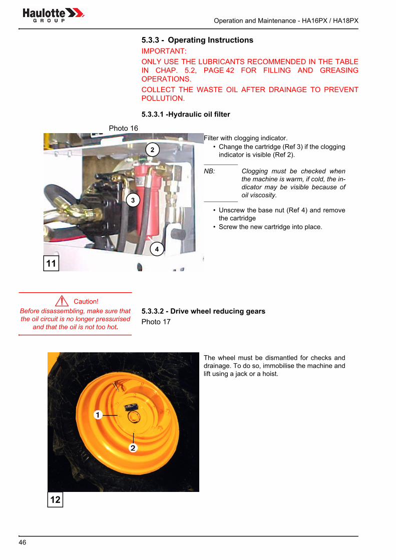
5.3.3.1 -Hydraulic oil filter
Before disassembling, make sure that the oil circuit is no longer pressurised
and that the oil is not too hot.
5.3.3.2 - Drive wheel reducing gearsPhoto 17
Photo 16Filter with clogging indicator.
• Change the cartridge (Ref 3) if the cloggingindicator is visible (Ref 2).
NB: Clogging must be checked whenthe machine is warm, if cold, the in-dicator may be visible because ofoil viscosity.
• Unscrew the base nut (Ref 4) and removethe cartridge
• Screw the new cartridge into place.
11
3
2
4
The wheel must be dismantled for checks anddrainage. To do so, immobilise the machine andlift using a jack or a hoist.
12

Operation and Maintenance - HA16PX / HA18PX
47
Caution!Check that the machine is correctly
secured and that the lifting equipment is of sufficient capacity
and in good condition.
Fluid level check:• turn the wheel so that one cap is on a horizontal line (1) and one cap
(2) is on a vertical line• unscrew the cap (1) and check the fluid level which should reach the
hole, add more if necessary.• screw the cap back on.• Draining:
- In the same position, unscrew both caps and let the oil drain out.- Fill as described above.- Screw the caps back on.
5.3.4 - List of consumables• Hydraulic filter cartridge• Air filter element• Diesel pre-filter• Diesel filter - motor oil filter.

Operation and Maintenance - HA16PX / HA18PX
48

Operation and Maintenance - HA16PX / HA18PX
49
6 - OPERATING INCIDENTS
REMINDER:Following the safety and maintenance instructions shouldenable you to avoid most of these incidents. Nevertheless, ifan incident does occur, it is vital to check if it is listed in tablebelow before carrying out any intervention. If so, simply followthe instructions. If it is not listed, contact the PINGUELY-HAULOTTE agent or the plant’s PINGUELY-HAULOTTEAfter Sales department.
Before diagnosing a failure, check that:• the fuel tank is not empty,• the batteries are properly charged,• the turntable and platform "palm button" emergency stop buttons are
unlocked,• the relays (platform control panel - turntable box) are correctly pushed
into their compartments.

Operation and Maintenance - HA16PX / HA18PX
50
INCIDENTS PROBABLE CAUSE SOLUTION
The motor does not start or stops
• Empty diesel tank • Defective fuse on printed circuit (in elec-tric box)• "Palm button" pushed in • Motor in "safety" mode: oil pressure, overheating, alternator charging, air filter clogged• Charging light indicator bulb blown• Air filter clogging light indicator on • Defective motor safety relay • Loose contact between battery cables and terminal
• Fill the tank • Replace defective fuses
• Reset• See manufacturer’s manual or contact After-sales
• Change the bulb• Change the cartridge• Replace the relay • Unscrew and clean the terminals
Insufficient pres-sure or power at the pump
• Clogged air filter • Motor regime insufficient • Oil leak on connector, hose, component • Clogged oil filter
• Change the filter.• Adjust the speed (contact After-sales)• Repair or replace (contact After-sales)• Replace the oil filter cartridge
No movement from the plat-form
•Turntable key selector in the wrong posi-tion• Overload in the platform • "Fail-safe" safety system not activated
• Manipulator operating fault • Selected movement electrovalve fault• Insufficient hydraulic oil • Tilt or slope > 5° up lifting movement disabled
• Put in the platform position
• Remove load• Press the "fail-safe" contact and hold down during movement • Replace manipulator (see After-sales)• Replace the electrovalve or its coil • Top up • Lower the arms and boom to reset
No high speed • Platform slightly extended • Lower the arms and boom completely
No steering movement
• Insufficient hydraulic oil • "Fail-safe" safety system not activated
• Top up • Press the "fail-safe" contact and hold down during movement
No travel, teles-cope out, boom lifting, arm lif-ting + buzzer sounding
• Slope or tilt >5° • First retract the telescope then lower the boom to reset
The turntable does not turn
• The locking pin is engaged in the chassis • Remove the pin
Noisy hydraulic pump
• Insufficient oil in the tank • Top up
Hydraulic pump cavitation
• Oil viscosity too high • Empty the circuit and replace with the recommended oil
No adhesion on one drive wheel
• Insufficient load on one wheel • Act on the blocking button

Operation and Maintenance - HA16PX / HA18PX
51
NB: In the turntable box, LEDS indicate the state of each outputto check that it is activated.
INCIDENTS PROBABLE CAUSE SOLUTION
Buzzer sounding • Tilt or slope > 5°
• Platform load close to limit • Hydraulic oil temperature too high
• Reset by retracting the telesco-ping and lowering the boom • Remove load• Leave to cool
The electropump does not work • Open battery circuit breaker • Defective fuses
• Close the battery circuit breaker • Replace the fuses

Operation and Maintenance - HA16PX / HA18PX
52
SQ1
SQ4
SQ5/SQ20
SQ6/SQ21
SQ2SQ3

Operation and Maintenance - HA16PX / HA18PX
53
7 - SAFETY SYSTEMS
7.1 - FUNCTION OF RELAYS AND FUSES IN THE TURNTABLE BOX (see wiring diagram)
7.2 - FUNCTION OF SAFETY CONTACTS(see wiring diagram)
KA2 Heat motor start FU3–80 A Accelerator circuit fuse
KP1 Heat motor stop FU4–30 A Main circuit fuse (motor)
KT2 Movement acceleration (electromo-tor) FU5–3 A Turntable movement control circuit
fuseKMG Mains power FU6–3 A Platform movement control circuit KA32 Battery-converter switching FU7–20 A Electrovalve supply circuit fuse
KA37 Converter supply FU8–5 A Turntable / platform control circuit fuse
KM1 Motorpump unit no. 1 control (bi-energy) FU9–20 A Accessory circuit fuse
KM2 Motorpump unit no. 2 control FU10–3 A Circuit fuse
FU1–10 A Motor stop circuit fuse FU11–250 AFU12–125 A
Electropump no. 1 circuit fuse Electropump no. 2 circuit fuse
QS1 Battery circuit breaker SQ3 Tilt reset if machine folded (boom)SB1 Palm button emergency stop (turntable) B1 Air filter contact. Motor cut off if clogged air filter
SB2 Palm button emergency stop (platform) B2 Motor temperature contact. Motor cut off if tem-perature too high
SQ1Tilt detector, disables arm lifting, boom lif-ting, telescoping, jib lifting and travel movements by breaking
B3 Oil pressure contact.Motor cut off if insufficient pressure
SQ4 Tilt reset if machine folded (arms) B4 Hydraulic oil temperature contact.Audible alert if temperature too high
SQ5 overload. SQ20 basket rotation
SQ6 overload - break Disables all movements from the platform SQ21 basket rotation
SQ2 Jib contactor >0°

Operation and Maintenance - HA16PX / HA18PX
54
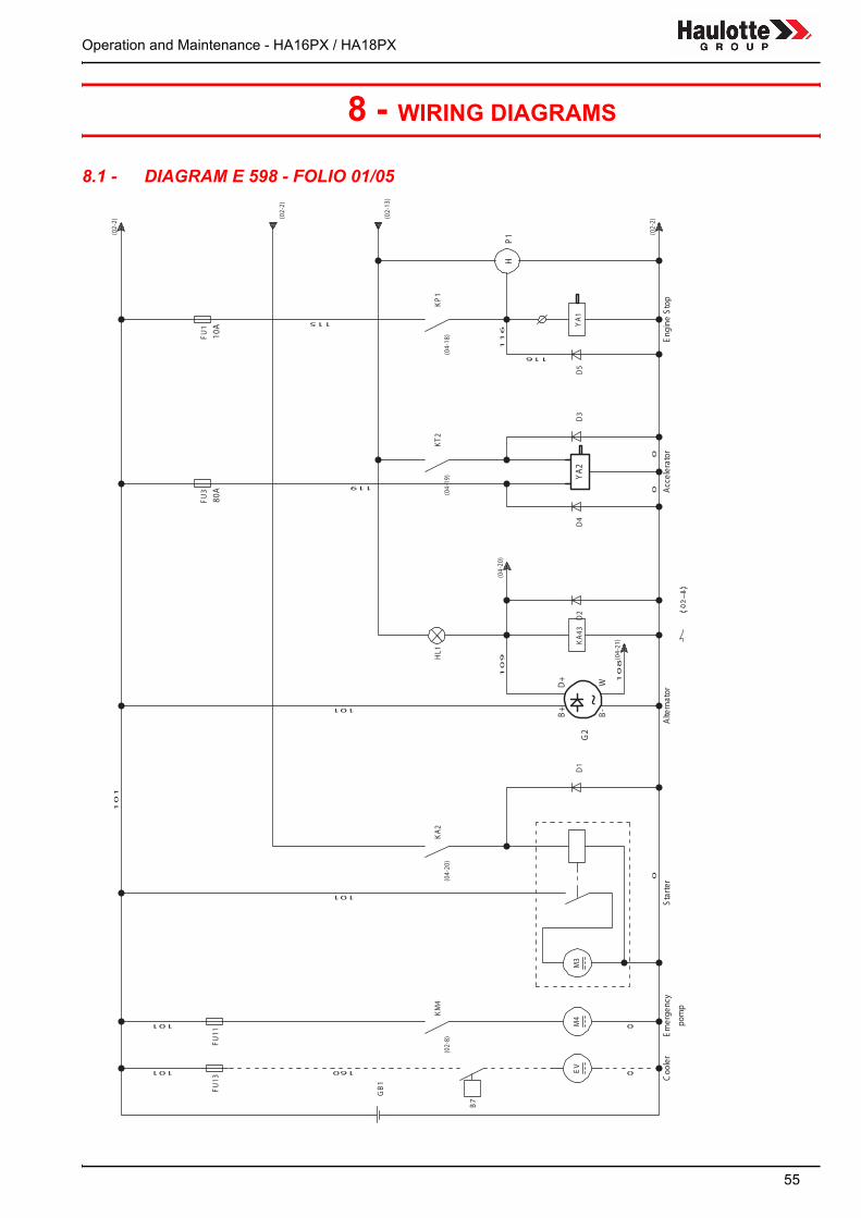
Operation and Maintenance - HA16PX / HA18PX
55
8 - WIRING DIAGRAMS
8.1 - DIAGRAM E 598 - FOLIO 01/05
H
D+ W
B-
B+
~
P1
YA2
G2
80A
10A
Coo
ler
St arte
rAlte
rnator
Accelerator
Eng
ineStop
Emerge
ncy
pomp
101
101
108
101 160
119
115
00
116
116
0
109
0
0
101
101
B7
GB1
EV
M4
M3
D1
D2
FU13
(02-2)
KM4
KA2
(02-2)
(02-2)
KA43
D4
HL1
FU3
(02-8)
D3
D5
KT2
FU1 Y
A1
KP1
( 04-20
)
(04-21
)
(04-20
)
(04-19
)(04-18
)
(02-13
)
FU11
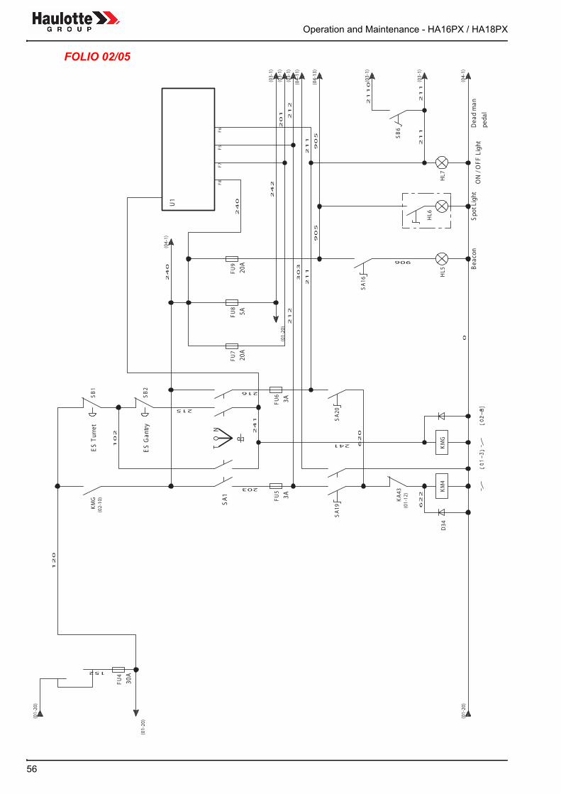
Operation and Maintenance - HA16PX / HA18PX
56
FOLIO 02/05
TO
NSA1
U1
F8F 7
F5F6
3 0A
3A3A
20A
5A20
A
ESTu
rret
ESGan
t ry
Bea
con
Spo
tLi ght
ON
/ OFF
Ligh
tDe a
dman
ped a
l
152
240
211
102
216
215
303
203
240
620
120
241
905
905
201
241
2110
242
212
212
906
622
0
211
211
211
FU4
KA43
D34
FU5
KMG
KM4
KMG
SB2
SB1
SA1 9
FU6
FU7
F U8
(04-1)
(03-1)
HL5FU
9
( 03-1)
(03-1)
SA20
SA16
(01-20
)
( 01-20
)
HL6
(01-20
)
(01-12
)
( 03-1)
( 02-10
)
( 03-1)
(01-20
)
(04-13
)
(04-1)
(04-11
)
HL7
SB6

Operation and Maintenance - HA16PX / HA18PX
57
FOLIO 03/05
U1
28.7
29.11
30.4
30.3
30.6
30. 5
4.6
4.9
30.9
3 0.8
4.14
4.15
30.11
30.10
29.10
29.9
29.8
29.7
4.12
3.2
29.12
1 710
1 819
3 53 4
15.8
1 5. 7
15. 3
15.6
3332
8.3
8 .12
8.6
8.9
8.11
1113Accelerator
DifferentialLock
GantryRotation
Compensation
Gantry
Pendular
Turret
Pendular
Gantry
Telescope
Turret
Telescope
Gantry
LSMSHS
FrontStearing
Startup
Turret
Statup
Gantry
Horn
Pendular
Compensation
GantryRotation
RearSteering
FrontSteering
MSHS
HS
MSHS
MSHS
Unbracking
8.10
MSHS
Compensation
Turret
407A
308
3110
402
419
401
306
418
412
411
406
405
410
409
708
707
804
805
807
117A
117B
901
408A
402A
401A
310A
311A
304
304A
814C
306A
814B
605
307
814B
399
813
814A
903A
401
310
814A
311
402
3100
SA2
SA3
YV18
A
(05-2)
YV11
SA8
SA9
SA11
SA4
SA5
SA6
SA7
YV18
BYV1 7
(05-2)
YV15
AYV15
BYV19
A
(02-20
)
( 02-20
)
YV19
B
(02-20
)
(02-20
)
(02-20
)
YV2 1
AYV21
BYV22
AYV22
BYV23
SA12
SB3
YV10
SB4
YV12
SB5
YV8
(04-1)
(05-2)
(04-1)
SA17
SQ21
SQ20

Operation and Maintenance - HA16PX / HA18PX
58
FOLIO 04/05
B4
B3
B2
B1
260
261
U1
30.2
39.3
3.3
41.2
4 2.2
46.2
47.2
40.2
27.4
27.3
27.2
27.1
27.7
3121
1 5.9
1 5. 4
205 2
.252
.314
4.1
4.2
4.3
Weighing
TiltDetector
Pendular
Boom
Arm
OilTemperature
OilPressure
MotorOil
Temperature
AirFilter
Dplus
W
DifferentialLock
LSValve
Horn
Buzzer
OilPressure
OilTemperature
AirFilter
EngineStop
Accélérator
Startup
3A
38.2
U1
HS
Orientation
206
109
214A
807B
807A
205
207
232
904
112
111
110
222
250
251
214
414A
417A
242
112A
210
108
201
111A
110A
242
150
605A
146
M M
SQ1
SQ5
HA1
(05-2)
(01-11
)(01-13
)
(02-15
)(02-20
)
(02-20
)
(02-20
)
(03-21
)
(05-2)
(03-20
)SQ6
VY14
AYV14
BYV13
SQ2
YV9
SQ3
SQ4
YV1
FU10
HA4
HL4
HL3
HL2
KP1
KT2
KA2

Operation and Maintenance - HA16PX / HA18PX
59
FOLIO 05/05
YX
Y
SM3 1
SM2
BA
U12 9
.130
.730
.15
30.12
3 0.14
3 0.13
29.15
2 9.2
29.3
29.5
29.6
28.9
28. 4
28.6
28. 3
28. 2
28.1
24.3
23.3
22.3
12.3
12.1
Orientation
Boom
NullPosition
NullPosition
NullPosition
DeadMan
DirectionAR
Arm
Translation
Orientation
Arm
Boom
Arm
Boom
U1
Proportional
Valve
Alarm
49.2
Y
SM4
28.15
Overload
29.4
26.3
Translation
Telescope
611C
420A
611B
403
512
420B
506
612
705
612A
211
212
517
516
511
510
0
512A
506A
403A
305
505
504
0
201
0
606
253
611A
2110 703
914
415
HL9
SA15
HA2
(03-21
)
(04-21
)
( 03-21
)
YV5
SA14
SA13
(03-21
)
( 04-10
)
YV2T O
RYV4
YV3
YV6
HL1
3

Operation and Maintenance - HA16PX / HA18PX
60

Operation and Maintenance - HA16PX / HA18PX
61
9 - HYDRAULIC DIAGRAMS
9.1 - DIAGRAM HA16/18PX REFERENCE P22513
10l/mn
5l/mn
6230
9524 10l/mn-5l/mn
GM/PSI
23 KW
MINI 1200T/MN
MAXI 2400T/MN
ou
7-8-14UNF
240b
L2
L1
38CM3
X
20b
1"1/2
SAE 3000
S
7-16-20UNF
X
1"
SAE 6000
B
1/2"G
240b
4734
PVEA
3191
11
3191
1/2"G
0 12
A
1/2"G
B
YV6
4734
PVEA
4734
PVEA
X1670
9655-85L/MN
10
270b
5PVG32 4256
210b
90b
8
YV1
YV6
YV8
YV10YV11YV12
PV
MV
GV
YV18a
100b
YV18b
TP
YV14a
YV14b
YV15a
YV15b
COMPENSATION
2
2
2
2
100/60 C510
80/40 C275
RECEPTEUR
PENDULAIRE
70/40 C675
EMETTEUR
TELESCOPAGE
65/50 C2285
V2
V1
3/8"G
3/8"G
22
43
35
54
5952
5113
AB
1/2"G
1/2"G
AB
100/50 C180
1/2"G
A
1/2"G
B
4734
PVEA
2000
1/2"G
AB
1/2"G
1/2"G
1/2"G
AB
70b
210b
TAILLE 75
7
2
17
3/8"G
3/8"G
1/4"G
1/4"G
3/8"G
V1
V2
3/8"G
YV2
YV3
YV4
YV5
YV13YV17
14
YV23
100b
M
GROUPE SECOURS
145b
3/8"G
3/8"G
Bxx
3193
1/4"G
P
3/4"G
LS
T
3/4"G
M
3193
100b
110/60 C1015
210b
3/8"G
V1
V2
3/8"G
CBCA-LHN
110/60 C510
CBBA-LHN
60/50 C2285
15
57
3/4"G
3/4"G
6 1/2"G
8 1/2"G
11
2 3/4"G
4
1/2"G
1 3/8"G
YV19a
YV19b
0 1
AB
PT
YV22a
YV22b
A BPT
65/50 C2975
ROTATION PANIER
13
3/8"G
3/8"G
1/2"G
1/2"G
12
A B
210b
3173
4216
PVEO
CBCA-LHN
CBBA-LHN
80/35 C92
3193
0 1
3193
YV21a
YV21b
T P
0 1
0 1
80/35 C92
DEUTZ
F3L2011F
30,9 KW
2300T/MN
MINI 850T/MN
MAXI 2400T/MN
3
9
10b
11
11
11
11
16
YV1
1"1/2
1/2"
1"
1
20
19
18
23
22
21
AB
PT
AB
PT
DR1
3/8"G
DR2
3/8"G
M1
3/4"G
M2
3/4"G
M3
3/4"G
M4
3/4"G
A
3/4"G
B
3/4"G
DR
1/2"G
DR3
3/8"G
DR4
3/8"G
TBR
3/4"G
M8
3/4"G
M7
3/4"G
M6
3/4"G
M5
3/4"G
YV17
YV23
YV13
YV11
YV9
YV12
YV8
YV10
1/4"G
1/4"G
1/4"G
1/4"G
LEVAGE
BRAS
AVANT
DROIT
AVANT
GAUCHE
ARRIERE
GAUCHE
ARRIERE
DROIT
ORIENTATION
TOURELLE
6230
7101 - 25L/MN
ORIENTATION
TOURELLE
T
3/8"G
P
1/4"G
FR AR
1/4"G
FR AV
1/4"G
B2
1/4"G
A2
1/4"G
A1
1/4"G
B1
1/4"G
FR 4/2
1/4"G
DIRECTION
AVANT
DIRECTION
ARRIERE
RELEVAGE
FLECHE
ROTATION
PANIER
BRAS
PENDULAIRE
6200
7101 - 25L/MN
6200
7000 - 10L/MN
A 1/2"G
A 1/2"G
B 1/2"G
B 1/2"G
B 1/2"G
B 1/2"G
A 1/2"G
A 1/2"G
P22513 e

Operation and Maintenance - HA16PX / HA18PX
62