self compensating eef.6 - rick.sparber.orgrick.sparber.org/sceef.pdf · a self compensating...
TRANSCRIPT

R. G. Sparber July 8, 2012 Page 1 of 66
A Self Compensating Electronic Edge
Finder, version 6.0
By R. G. Sparber
Copyleft protects this document.1
Purpose This article
describes an
Electronic Edge
Finder which
connects
directly to the
cutter and
spindle on a
lathe without
any
modifications to
the machine. It
can detect when
the cutter comes
in contact with
the work piece.
While the
common EEF can tell the difference between an open circuit and a resistance less
than around 500 ohms, this new EEF can tell when the resistance changes from
0.01 ohm down to 0.0098 ohms. In this way it deals with the low resistance of the
machine rather than being insulated from it2.
A test current of 20 milliamps, comparable to what is used with commonly
available EEFs, is employed.
1 You are free to copy and distribute this document but not change it.
2 If you own a lathe with a spindle to cutter resistance of greater than 2 ohms or a mill with a spindle to table
resistance of greater than 2 ohms, then a simpler EEF circuit is available at http://rick.sparber.org/rctf.pdf.
R. G. Sparber July 8, 2012 Page 2 of 66
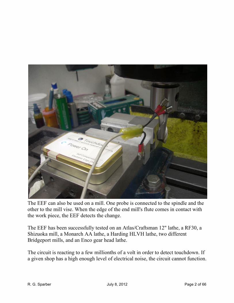
The EEF can also be used on a mill. One probe is connected to the spindle and the
other to the mill vise. When the edge of the end mill's flute comes in contact with
the work piece, the EEF detects the change.
The EEF has been successfully tested on an Atlas/Craftsman 12" lathe, a RF30, a
Shizuoka mill, a Monarch AA lathe, a Harding HLVH lathe, two different
Bridgeport mills, and an Enco gear head lathe.
The circuit is reacting to a few millionths of a volt in order to detect touchdown. If
a given shop has a high enough level of electrical noise, the circuit cannot function.

R. G. Sparber July 8, 2012 Page 3 of 66
Contents Purpose ....................................................................................................................... 1
YouTube Video .......................................................................................................... 4
Background ................................................................................................................ 5
The Self Compensating EEF ...................................................................................... 8
EFF Operation on a Lathe .......................................................................................... 9
Shop Experience ......................................................................................................10
Schematic .................................................................................................................14
Interfacing with a CNC System ...............................................................................15
Parts Placement ........................................................................................................16
Parts List...................................................................................................................18
Trim Pot Adjustment Procedure ..............................................................................20
On a Lathe ............................................................................................................20
On a Mill ..............................................................................................................20
The Magnetic Probes ...............................................................................................21
Theory of Operation .................................................................................................23
A Common Electronic Edge Finder .....................................................................23
The New Electronic Edge Finder .........................................................................23
System Block Diagram ............................................................................................24
Test Current Generator ........................................................................................25
Power Control ......................................................................................................26
Cutter to Spindle Resistance ................................................................................27
Voltage Amplifier ................................................................................................28
Touchdown Amplifier ..........................................................................................29
Automatic Threshold Generator ..........................................................................31
Touchdown LED ..................................................................................................36
Offset Adjustment ....................................................................................................37
The Calibration Phase ..............................................................................................42
The Touchdown Phase .............................................................................................44
The Effect of Unwanted Electrical Noise ................................................................46

R. G. Sparber July 8, 2012 Page 4 of 66
Circuit Behavior As Rx Varies .................................................................................49
A Peak Into the Design Process ...............................................................................52
Scope Pictures ..........................................................................................................56
PSpice 9.1 Simulation ..............................................................................................59
The Test Bed ............................................................................................................60
Magnified Schematic ...............................................................................................63
Acknowledgements ..................................................................................................66
YouTube Video
You can see a YouTube video of this device being used on a lathe at
http://www.youtube.com/watch?v=XgFRIsJrA0s&list=UUQowQlSfFxybveyBDV
OHXxw&index=1&feature=plcp
R. G. Sparber July 8, 2012 Page 5 of 66
Background
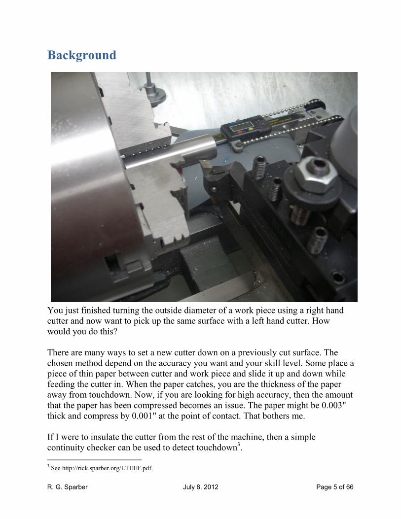
You just finished turning the outside diameter of a work piece using a right hand
cutter and now want to pick up the same surface with a left hand cutter. How
would you do this?
There are many ways to set a new cutter down on a previously cut surface. The
chosen method depend on the accuracy you want and your skill level. Some place a
piece of thin paper between cutter and work piece and slide it up and down while
feeding the cutter in. When the paper catches, you are the thickness of the paper
away from touchdown. Now, if you are looking for high accuracy, then the amount
that the paper has been compressed becomes an issue. The paper might be 0.003"
thick and compress by 0.001" at the point of contact. That bothers me.
If I were to insulate the cutter from the rest of the machine, then a simple
continuity checker can be used to detect touchdown3.
3 See http://rick.sparber.org/LTEEF.pdf.
R. G. Sparber
the cutter that will cause a current to flow at touchdown. Although I was unable to
find the proper components to try out this idea, I have no doubt that it would work.
4 of the atlas_craftsman Yahoo group.
5 See http://rick.sparber.org/ueef.pdf
6 of the atlas_craftsman Yahoo group.
July 8, 2012
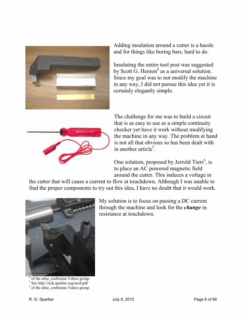
Adding insulation around a cutter is a hassle
and for things like boring bars, hard to do
Insulating the entire tool post was suggested
by Scott G. Henion4 as a universal solution.
Since my goal was to not modify the machine
in any way, I did not pursue this idea yet it is
certainly elegantly simple.
The challenge for me was to build a circuit
that is as easy to use as a simple continuity
checker yet have it work without
the machine in any way. The problem at hand
is not all that obvious so has been dealt with
in another article5.
One solution, proposed by Jerrold Tiers
to place an AC powered magnetic field
around the cutter. This induces a voltage in
the cutter that will cause a current to flow at touchdown. Although I was unable to
find the proper components to try out this idea, I have no doubt that it would work.
My solution is to focus on passing a DC current
through the machine and look for the change
resistance at touchdown.
Page 6 of 66
Adding insulation around a cutter is a hassle
, hard to do.
the entire tool post was suggested
as a universal solution.
Since my goal was to not modify the machine
in any way, I did not pursue this idea yet it is
to build a circuit
as easy to use as a simple continuity
checker yet have it work without modifying
. The problem at hand
is not all that obvious so has been dealt with
One solution, proposed by Jerrold Tiers6, is
powered magnetic field
around the cutter. This induces a voltage in
the cutter that will cause a current to flow at touchdown. Although I was unable to
find the proper components to try out this idea, I have no doubt that it would work.
focus on passing a DC current
change in

R. G. Sparber July 8, 2012 Page 7 of 66
The controversy started when I discovered
that the task was easy to do if I used 1 amp
as my test current. Some felt that this
could cause arcing inside the bearings and
lead to pitting of the surface. Since it is
impossible to prove that this is not the case
even when the applied voltage is only
0.01V, I decided to develop another circuit
that used only 0.15 amps. It works well
but required the turning of a knob to
compensate for variations in resistance. That bothers me.
So this time around I have developed a circuit that passes only 20 mA at no more
than 0.7V through the machine and automatically compensates for resistance.
Since Electronic Edge Finders bought at
Enco® put out about this much current and
more voltage, I think I can safely say that
any concerns about damaging the bearings
can now be put to rest.
Some have suggested methods involving touchdown with the machine running.
There is a "Catch-227" here. The instant the cutter touches the reference surface, it
will slice away the surface. So you will never touch down for more than an instant
and then the reference surface has been damaged.
7 See http://en.wikipedia.org/wiki/Catch-22_(logic)
R. G. Sparber July 8, 2012 Page 8 of 66
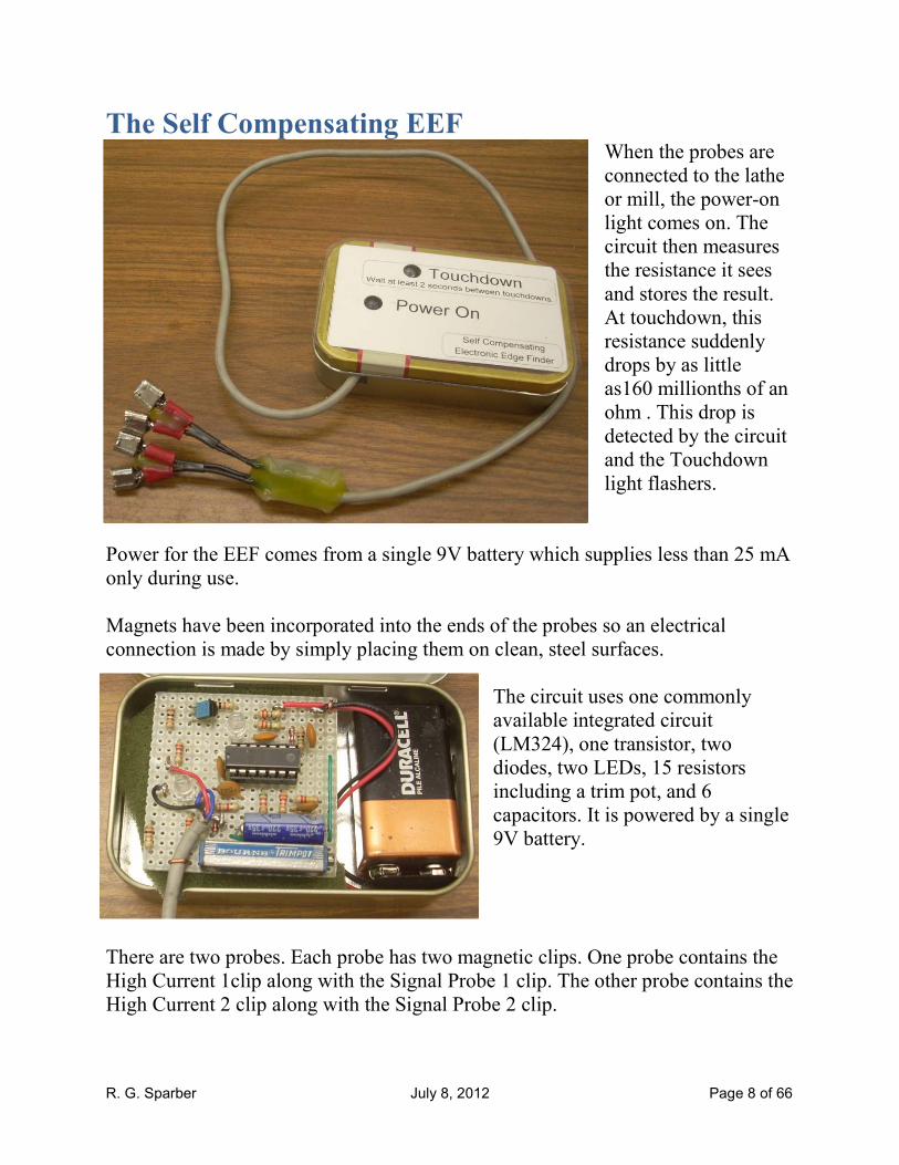
The Self Compensating EEF When the probes are
connected to the lathe
or mill, the power-on
light comes on. The
circuit then measures
the resistance it sees
and stores the result.
At touchdown, this
resistance suddenly
drops by as little
as160 millionths of an
ohm . This drop is
detected by the circuit
and the Touchdown
light flashers.
Power for the EEF comes from a single 9V battery which supplies less than 25 mA
only during use.
Magnets have been incorporated into the ends of the probes so an electrical
connection is made by simply placing them on clean, steel surfaces.
The circuit uses one commonly
available integrated circuit
(LM324), one transistor, two
diodes, two LEDs, 15 resistors
including a trim pot, and 6
capacitors. It is powered by a single
9V battery.
There are two probes. Each probe has two magnetic clips. One probe contains the
High Current 1clip along with the Signal Probe 1 clip. The other probe contains the
High Current 2 clip along with the Signal Probe 2 clip.
R. G. Sparber July 8, 2012 Page 9 of 66
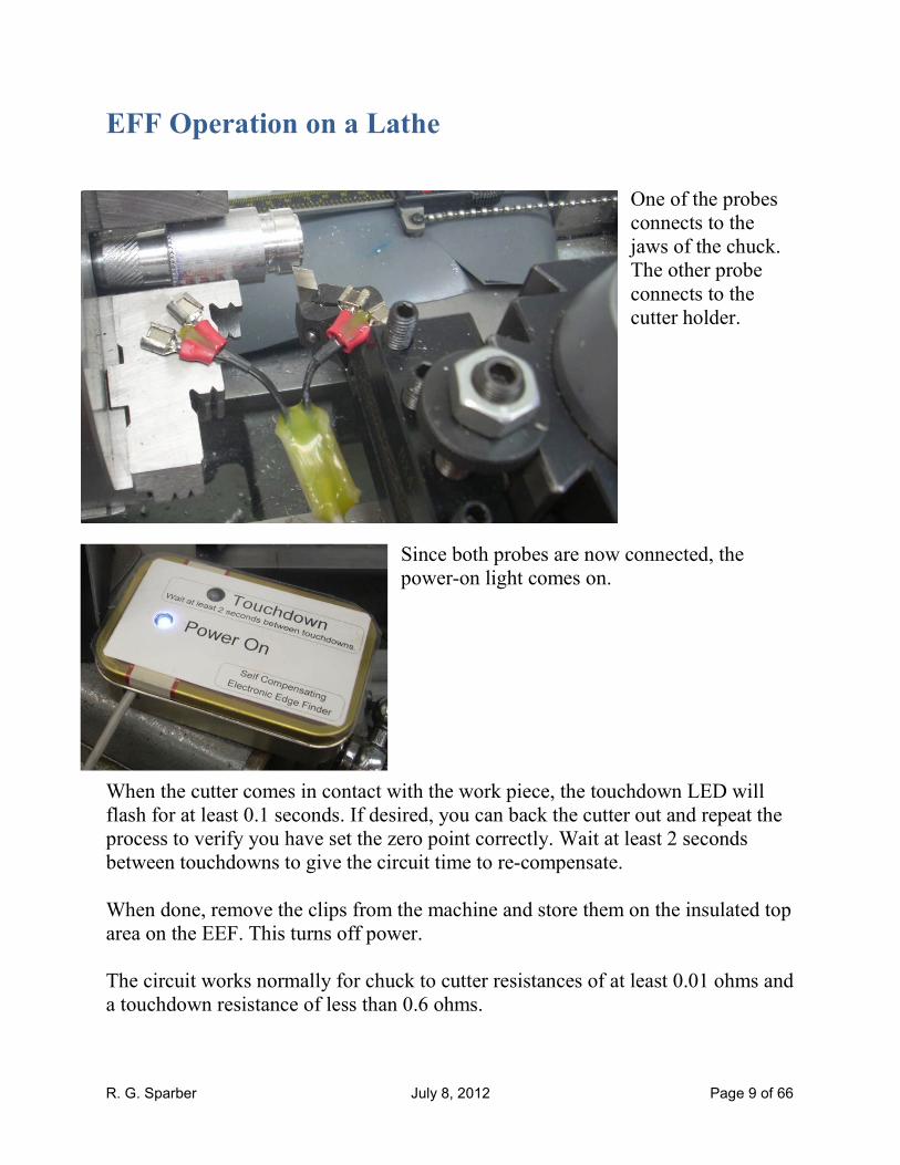
EFF Operation on a Lathe
One of the probes
connects to the
jaws of the chuck.
The other probe
connects to the
cutter holder.
Since both probes are now connected, the
power-on light comes on.
When the cutter comes in contact with the work piece, the touchdown LED will
flash for at least 0.1 seconds. If desired, you can back the cutter out and repeat the
process to verify you have set the zero point correctly. Wait at least 2 seconds
between touchdowns to give the circuit time to re-compensate.
When done, remove the clips from the machine and store them on the insulated top
area on the EEF. This turns off power.
The circuit works normally for chuck to cutter resistances of at least 0.01 ohms and
a touchdown resistance of less than 0.6 ohms.

R. G. Sparber July 8, 2012 Page 10 of 66
Shop Experience
Normally I would take two or more cuts of equal in-feed, measure the result, take
an average, and have a correction factor that will get me the desired Depth Of Cut.
Then the next cut would use this correction factor at the same in-feed and the
resulting finish cut would be as close as possible to idea. This procedure
compensates for time invariant error but nothing can compensate for time variant
error which is random.
I see the EEF being used in a different situation. To start, I would make one or
more calibration cuts which begin at touchdown each time. These cuts would tell
me the average DOC for a given in-feed.
Notice that in the first case my cut includes the initial and final spring of the cutter.
In the second case, using the EEF, my cut only includes the spring at the end of the
cut. Initially there is no spring because the cutter is just barely touching the
surface.
I'm now ready to start machining. I touchdown using the EEF and set my zero.
When I feed in by the calibrated in-feed, I should be able to predict the actual DOC
to within the accuracy of the lathe.
The calibration must be done under the same conditions as the cut just performed.
I started by turning a test
piece out of 6061
aluminum. The lathe is a
12" Atlas/Craftsman in
very good shape (IMHO).
The corners of the test
piece have been deburred
and then cleaned with
alcohol.
The cutter was also cleaned
with alcohol. All surfaces
are then dried.

R. G. Sparber July 8, 2012 Page 11 of 66
Then I used my EEF to set my in-feed dial to zero at touchdown. With the EEF a
safe distance away, I fed in 0.005" on my cross feed dial.
R. G. Sparber July 8, 2012 Page 12 of 66
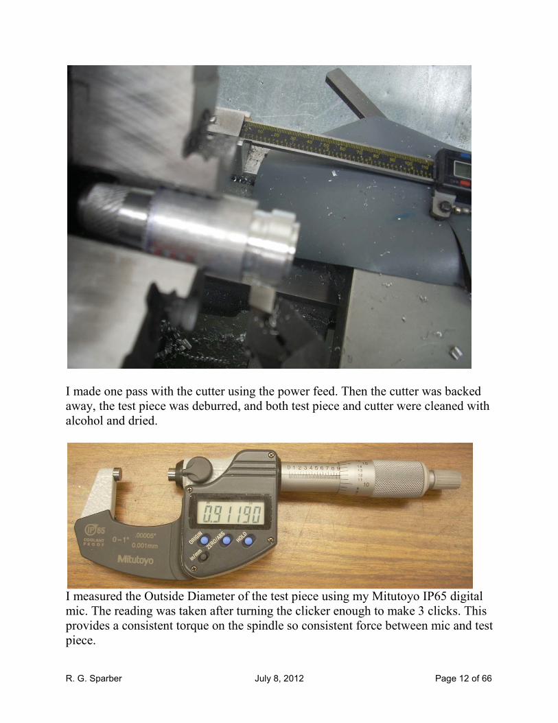
I made one pass with the cutter using the power feed. Then the cutter was backed
away, the test piece was deburred, and both test piece and cutter were cleaned with
alcohol and dried.
I measured the Outside Diameter of the test piece using my Mitutoyo IP65 digital
mic. The reading was taken after turning the clicker enough to make 3 clicks. This
provides a consistent torque on the spindle so consistent force between mic and test
piece.

R. G. Sparber July 8, 2012 Page 13 of 66
I then repeated the process by first establishing a new zero on my in-feed dial.
Then feeding in 0.005", taking a cut, and measuring the resulting diameter.
Here is the raw data plus reduction to average and deviation:
Pass mic'd diameter, inches
change in radius,
inches
1st ref 0.91940 n/a
1 0.91190 0.00375
2 0.90445 0.00373
3 0.89815 0.00315
4 0.89070 0.00372
5 0.88290 0.00390
6 0.87675 0.00307
average = 0.0036
deviation (+/-) = 0.0003
In each case I fed in 0.005" and got a Depth Of Cut of 0.0036" ± 0.0003.
Now, the challenge during machining is to get as close to a final DOC of 0.0036"
as possible. Then the correction factor will be as accurate as possible.
Note that if you calibrate all of the cutters you plan to use, you can change cutters
and maintain the same accuracy. It is important to understand that this correction
factor depends on all parameters of the cut being the same. It also depends on the
cutter not dulling "too much". At some point you will have to at least recalibrate
and later sharpen the cutter.
The above procedure does not replace the standard method of taking repeated cuts
to get to a given diameter. It is just another "tool in the box" to solve the sticky
problem of starting with a finished reference surface.
R. G. Sparber July 8, 2012 Page 14 of 66
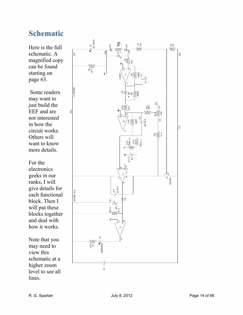
Schematic
Here is the full
schematic. A
magnified copy
can be found
starting on
page 63.
Some readers
may want to
just build the
EEF and are
not interested
in how the
circuit works.
Others will
want to know
more details.
For the
electronics
geeks in our
ranks, I will
give details for
each functional
block. Then I
will put these
blocks together
and deal with
how it works.
Note that you
may need to
view this
schematic at a
higher zoom
level to see all
lines.

R. G. Sparber July 8, 2012 Page 15 of 66
Interfacing with a CNC System
You can substitute an opto isolator for D4 so
the EEF can safely interface with a CNC
system. At touchdown, you would get
conduction through the opto.
If your computer needs to see a high to
low transition at touchdown, connect
the - lead of the opto to the computer's
ground. Connect the + lead to a 1K
resistor. The other end of the resistor
goes to +5 provided by the computer.
Then connect the + lead to the input
port so the software can see it.
If your computer needs to see a low to
high transition at touchdown, connect
the + lead of the opto to the
computer's +5V. connect the - lead to
a 1K resistor. The other end of the
resistor connects to ground. Connect
the - lead to the input port so the
software can see it. This may not
work if interfacing to TTL but should
be fine for CMOS. See your interface
specs.

R. G. Sparber July 8, 2012 Page 16 of 66
Parts Placement This is not the ideal placement of parts but is how I did it in my first prototype. It
shows you what the various parts look like.
My R6 is larger than the trim pots commonly found today. You will see that the
circuit board artwork uses the more compact style.

R. G. Sparber July 8, 2012 Page 17 of 66
This layout can be done as a circuit board with copper on only the bottom side.
The purple areas are ground and are designed to quiet the most sensitive nodes. If
you wish to go double sided copper, make the top layer all ground. Thermal
breaks8 around all connections to ground would help during the soldering process.
To avoid problems, I suggest you measure each resistor before soldering it in
place.
8 A thermal break looks like a miniature 4 spoke wheel. It provides an electrical
connection while reducing the amount of heat needed during soldering.
R. G. Sparber July 8, 2012 Page 18 of 66
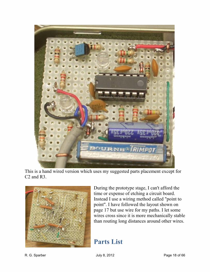
This is a hand wired version which uses my suggested parts placement except for
C2 and R3.
During the prototype stage, I can't afford the
time or expense of etching a circuit board.
Instead I use a wiring method called "point to
point". I have followed the layout shown on
page 17 but use wire for my paths. I let some
wires cross since it is more mechanically stable
than routing long distances around other wires.
Parts List
R. G. Sparber July 8, 2012 Page 19 of 66
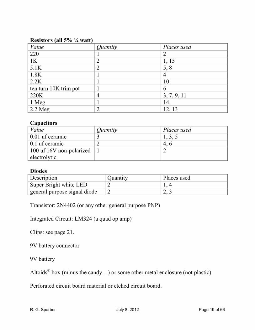
Resistors (all 5% ¼ watt)
Value Quantity Places used
220 1 2
1K 2 1, 15
5.1K 2 5, 8
1.8K 1 4
2.2K 1 10
ten turn 10K trim pot 1 6
220K 4 3, 7, 9, 11
1 Meg 1 14
2.2 Meg 2 12, 13
Capacitors
Value Quantity Places used
0.01 uf ceramic 3 1, 3, 5
0.1 uf ceramic 2 4, 6
100 uf 16V non-polarized
electrolytic
1 2
Diodes
Description Quantity Places used
Super Bright white LED 2 1, 4
general purpose signal diode 2 2, 3
Transistor: 2N4402 (or any other general purpose PNP)
Integrated Circuit: LM324 (a quad op amp)
Clips: see page 21.
9V battery connector
9V battery
Altoids® box (minus the candy…) or some other metal enclosure (not plastic)
Perforated circuit board material or etched circuit board.

R. G. Sparber July 8, 2012 Page 20 of 66
Trim Pot Adjustment Procedure
In order to maximize sensitivity to touchdown while minimizing sensitivity to
electrical noise, we need to connect the circuit up to the lathe or mill.
On a Lathe
Degrease a small patch of the ways. Then place all connectors on this patch. Adjust
R6, the trim pot, until the touchdown LED just stops flickering.
Move the probes so one is on the cutter or tool post while the other is on the chuck.
Put a metal bar in the chuck. Wait a few seconds and then do a trial touchdown.
The touchdown LED should flash for at least 0.1 seconds. If the touchdown LED
flickers, slightly adjust the trim pot until it remains dark.
On a Mill
Degrease a small patch of the table. Then place all connectors on this patch. Adjust
R6, the trim pot, until the touchdown LED just stops flickering.
Move the probes so one is on the spindle while the other is on the vise. Put a metal
block in the vise. Wait a few seconds and then do a trial touchdown. If the
touchdown LED flickers, slightly adjust the trim pot until it remains dark. The
touchdown LED should flash for at least 0.1 seconds.
This adjustment should not be needed again unless the EEF is moved to a different
shop that has significantly different electrical noise.
It is possible that the electrical noise level around the machine is so high that the
circuit cannot operate correctly. Keeping the test leads short will minimize this
effect. Some detective work may be needed to find the source of the noise. I
welcome you to contact me at [email protected] if you have problems.
R. G. Sparber July 8, 2012 Page 21 of 66
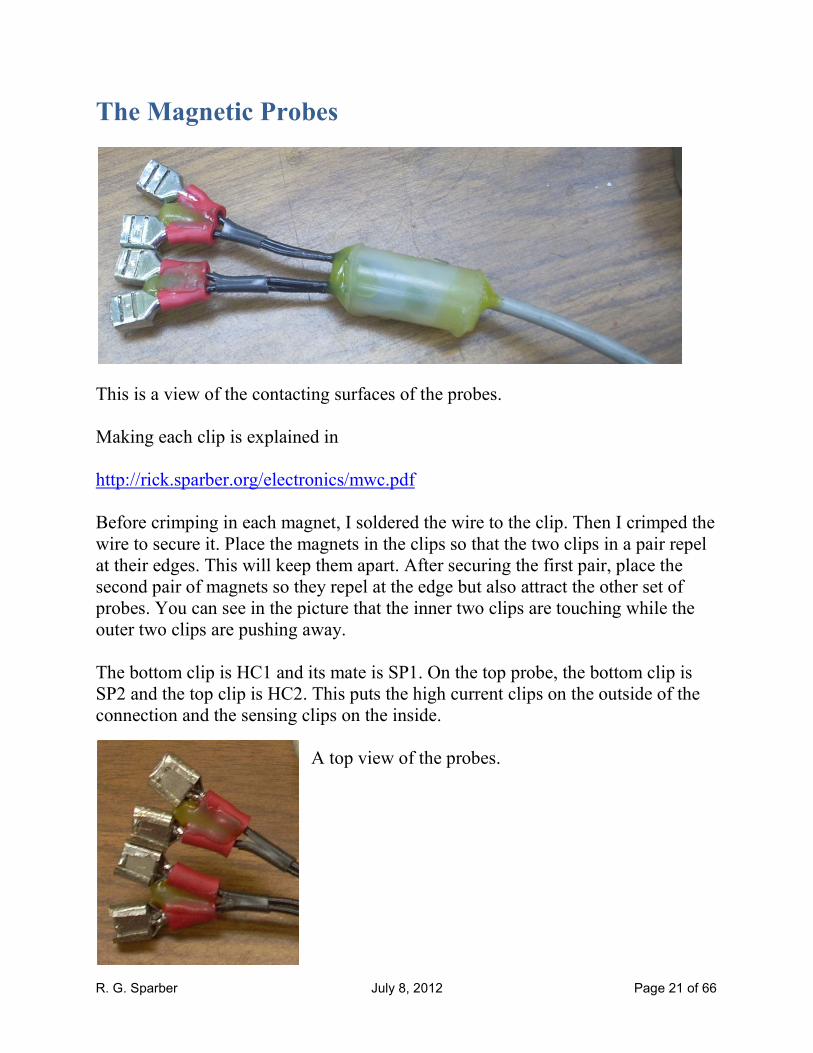
The Magnetic Probes
This is a view of the contacting surfaces of the probes.
Making each clip is explained in
http://rick.sparber.org/electronics/mwc.pdf
Before crimping in each magnet, I soldered the wire to the clip. Then I crimped the
wire to secure it. Place the magnets in the clips so that the two clips in a pair repel
at their edges. This will keep them apart. After securing the first pair, place the
second pair of magnets so they repel at the edge but also attract the other set of
probes. You can see in the picture that the inner two clips are touching while the
outer two clips are pushing away.
The bottom clip is HC1 and its mate is SP1. On the top probe, the bottom clip is
SP2 and the top clip is HC2. This puts the high current clips on the outside of the
connection and the sensing clips on the inside.
A top view of the probes.

R. G. Sparber July 8, 2012 Page 22 of 66
Of critical importance
is the cable that
connects between the
circuit and these
probes. It is a coaxial
cable with 3
conductors inside9.
This cable insures that
noise cannot enter the
circuit via the cable.
The ground shield of
the cable connects to
SP2.
Heat glue was used to pot the splice between coaxial cable and probe wires.
The coaxial cable is about 12" long and the probe wires are about 1" long.
Minimize the area defined by the probe cables and clips since it is where much of
the electrical noise comes from.
Except around swarf, I do like the magnetic clip approach. Given that swarf
completely disrupts the finding of touchdown, it is reasonable to assume that the
area is free of the stuff. Shop experience may change my mind.
9 I scrounged this cable from an old Apple Computer system.

R. G. Sparber July 8, 2012 Page 23 of 66
Theory of Operation
A Common Electronic Edge Finder
Common EEFs are often used on manual10 mills
to find the exact point where the center of
rotation of the spindle is a known distance from a
reference surface. These EEFs consist of a
conductive body that is held in the spindle. A
conductive cylinder, the probe, extends out the
bottom which is insulated from the body. A
battery is connected to the conductive body. The
other end of the battery connects to an LED and
resistor in series. The LED lights when current
flows out the probe, through the work piece, into
the machine, and out the spindle. This works
very well because there is a large change in
resistance from essentially infinite to zero
resistance. I am not aware of a similar device
that is used on a manual lathe.
The New Electronic Edge Finder
The EEF presented here works in a different environment. No attachment similar
to a common EEF is used.
In the case of a lathe, one wire is connected to the spindle and the other wire
connects to the cutter. This resistance measures as a dead short using a commonly
available Volt-Ohm meter. But if you have the right equipment, you will find that
the resistance can be as small as 0.010 ohms. When the cutter comes in contact
with the work piece held in the spindle, this resistance falls by as little as 0.16 milli
ohms. The circuit is sensitive to this tiny drop in resistance. For more information,
please see http://rick.sparber.org/ueef.pdf .
The circuit uses the pre-touchdown resistance to calculate a threshold and then
monitors for a drop in this resistance that indicates touchdown has occurred.
10 Versus a CNC mill.

R. G. Sparber July 8, 2012 Page 24 of 66
System Block Diagram
Starting on the left, we have a test current generator. It applies 20 mA to the
resistance between cutter and spindle. It also signals the automatic power control
circuit. As long as the test current flows, power is applied to the rest of the circuit.
The cutter to spindle resistance can be as small as 10 milli ohms so the voltage
generated by the 20 mA test current is only 200 micro volts. The voltage picked up
by a TV antenna is on the order of tens of micro volts. So our test voltage is very
small.
Our drop in resistance at touchdown is on the order of 0.16 milli ohms which
generates a change in voltage of -3.2 micro volts. It is this tiny drop in voltage that
the circuit is able to detect.
The circuit has two phases. In the first phase it is constantly calibrating to the non-
touchdown resistance. In the second phase it is detecting the sudden drop in
resistance.
During calibration, the voltage generated across the cutter to spindle resistance is
amplified by a factor of -122 by the voltage amplifier. It then passes through the
touchdown amplifier which multiplies it by -1. The voltage is then applied to the
automatic threshold generator which computes and stores the proper threshold that
must be crossed in order to signal touchdown.
During the second phase, the circuit reacts to only the sudden drop in resistance. It
causes a tiny drop in the voltage generated across the cutter to spindle resistance.
This voltage drop is amplified by the voltage amplifier just like during the first
phase. But then it is further amplified by -100 in the touchdown amplifier. The
signal is then sent to the touchdown detector where the threshold has already been
set. The detector sends a signal to the touchdown LED driver which in turn lights
the touchdown LED.
R. G. Sparber July 8, 2012 Page 25 of 66
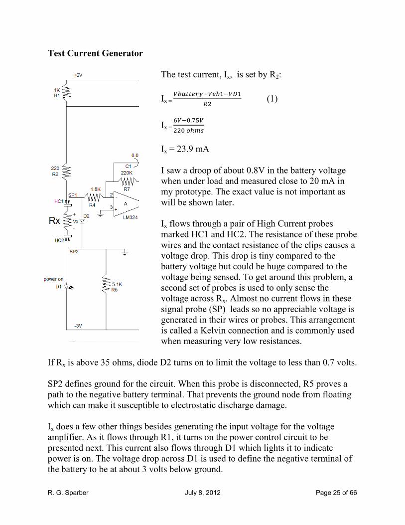
Test Current Generator
The test current, Ix, is set by R2:
Ix = ��������������
�� (1)
Ix = ���.����������
Ix = 23.9 mA
I saw a droop of about 0.8V in the battery voltage
when under load and measured close to 20 mA in
my prototype. The exact value is not important as
will be shown later.
Ix flows through a pair of High Current probes
marked HC1 and HC2. The resistance of these probe
wires and the contact resistance of the clips causes a
voltage drop. This drop is tiny compared to the
battery voltage but could be huge compared to the
voltage being sensed. To get around this problem, a
second set of probes is used to only sense the
voltage across Rx. Almost no current flows in these
signal probe (SP) leads so no appreciable voltage is
generated in their wires or probes. This arrangement
is called a Kelvin connection and is commonly used
when measuring very low resistances.
If Rx is above 35 ohms, diode D2 turns on to limit the voltage to less than 0.7 volts.
SP2 defines ground for the circuit. When this probe is disconnected, R5 proves a
path to the negative battery terminal. That prevents the ground node from floating
which can make it susceptible to electrostatic discharge damage.
Ix does a few other things besides generating the input voltage for the voltage
amplifier. As it flows through R1, it turns on the power control circuit to be
presented next. This current also flows through D1 which lights it to indicate
power is on. The voltage drop across D1 is used to define the negative terminal of
the battery to be at about 3 volts below ground.

R. G. Sparber July 8, 2012 Page 26 of 66
Power Control
The flow of Ix through R1 causes the emitter-base junction voltage of Q1 to rise.
When this voltage rises until Q1 turns on. Then the voltage is almost constant at
0.75V. This means that �.���� = 0.75 mA flows through R1 and the rest flows out of
the base of Q1. So my base drive is 20 mA - 0.75 mA = 19.3 mA. The collector
current on Q1 is far less than 20 mA so Q1 is driven deep into saturation. The quad
op amp integrated circuit is then essentially tied to Vcc, the positive terminal of the
battery.
When HC1 is disconnected from the lathe or mill, Ix drops to zero, Q1 turns off,
and power is removed from the circuit.
R. G. Sparber July 8, 2012 Page 27 of 66
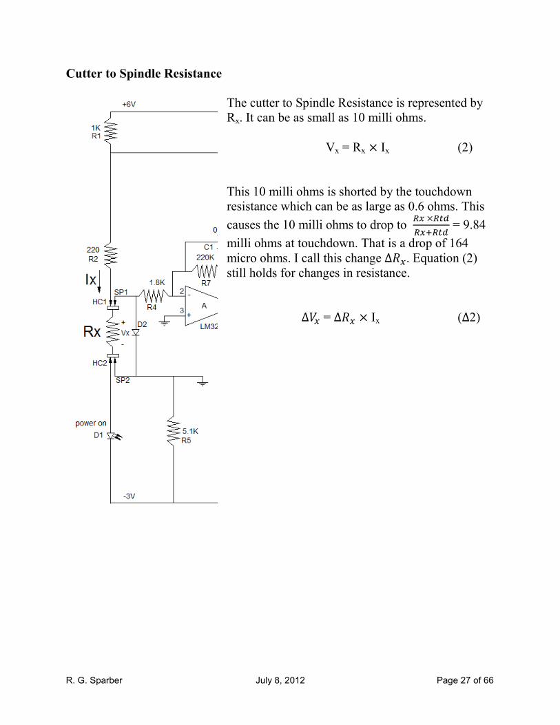
Cutter to Spindle Resistance
The cutter to Spindle Resistance is represented by
Rx. It can be as small as 10 milli ohms.
Vx = Rx × Ix (2)
This 10 milli ohms is shorted by the touchdown
resistance which can be as large as 0.6 ohms. This
causes the 10 milli ohms to drop to ����������� = 9.84
milli ohms at touchdown. That is a drop of 164
micro ohms. I call this change ∆��. Equation (2) still holds for changes in resistance.
∆�� = ∆�� × Ix (∆2)

R. G. Sparber July 8, 2012 Page 28 of 66
Voltage Amplifier
The voltage generated across Rx
is carried by probes SP1 and SP2
to the voltage amplifier. The
output voltage is at pin 1 and is
called V1:
V1 = GA × Vx
Where GA = - ���� (3)
V1 = - �����. � × �� = - 122 Vx
assuming there is no input offset
voltage. I will deal with this
subject later.
Capacitor C1 in conjunction with R7 causes the gain of this amplifier to drop as the
signal frequency rises. We want to pass some high frequencies in order to see
touchdown but at the same time we do not want to see electrical noise present in
the room. Given that we are trying to process micro volts of signal, it doesn't take
much noise to cause trouble.
The gain is cut to - ��√� = - 86 when the frequency equals
�×"×��×# = 72 Hz and
continues to fall as the noise's frequency rises.
In the time domain, the amplifier has a time constant of �7 × &1 = 2.2 milliseconds. This is the same time constant as the touchdown amplifier but 50
times smaller the next largest time constant. This fact will come in handy when
analyzing other functional blocks.
The amplifier will also operate on changes in voltage which I will designate as ∆:
∆V1 = GA × ∆Vx
Where GA = - ���� (∆3)
R. G. Sparber July 8, 2012 Page 29 of 66
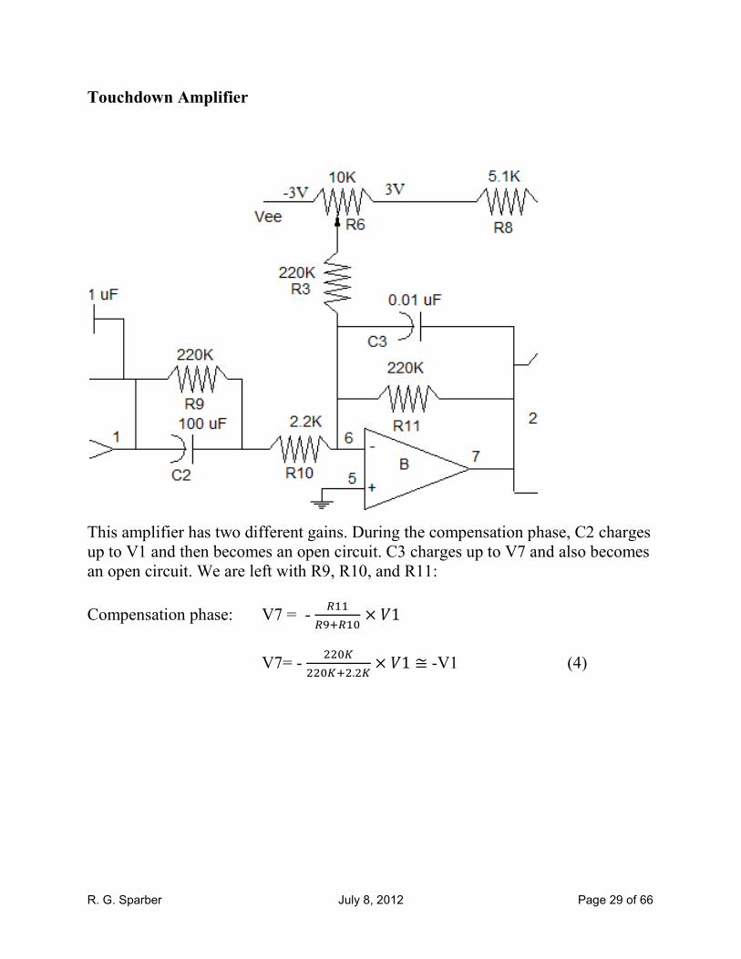
Touchdown Amplifier
This amplifier has two different gains. During the compensation phase, C2 charges
up to V1 and then becomes an open circuit. C3 charges up to V7 and also becomes
an open circuit. We are left with R9, R10, and R11:
Compensation phase: V7 = - �
�(��� × �1
V7= - ����
������.�� × �1 ≅ -V1 (4)
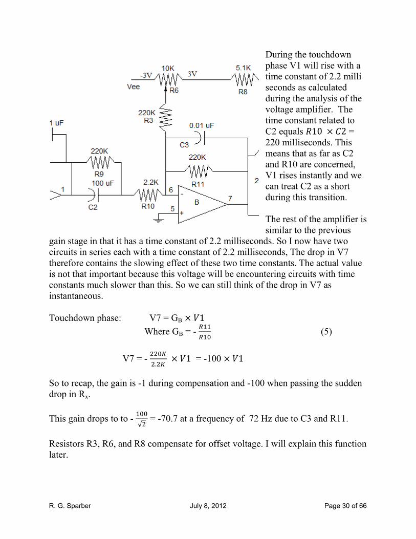
R. G. Sparber July 8, 2012 Page 30 of 66
During the touchdown
phase V1 will rise with a
time constant of 2.2 milli
seconds as calculated
during the analysis of the
voltage amplifier. The
time constant related to
C2 equals �10 × &2 = 220 milliseconds. This
means that as far as C2
and R10 are concerned,
V1 rises instantly and we
can treat C2 as a short
during this transition.
The rest of the amplifier is
similar to the previous
gain stage in that it has a time constant of 2.2 milliseconds. So I now have two
circuits in series each with a time constant of 2.2 milliseconds, The drop in V7
therefore contains the slowing effect of these two time constants. The actual value
is not that important because this voltage will be encountering circuits with time
constants much slower than this. So we can still think of the drop in V7 as
instantaneous.
Touchdown phase: V7 = GB × �1
Where GB = - ��� (5)
V7 = - �����.�� × �1 = -100 × �1
So to recap, the gain is -1 during compensation and -100 when passing the sudden
drop in Rx.
This gain drops to to - ��√� = -70.7 at a frequency of 72 Hz due to C3 and R11.
Resistors R3, R6, and R8 compensate for offset voltage. I will explain this function
later.
R. G. Sparber July 8, 2012 Page 31 of 66
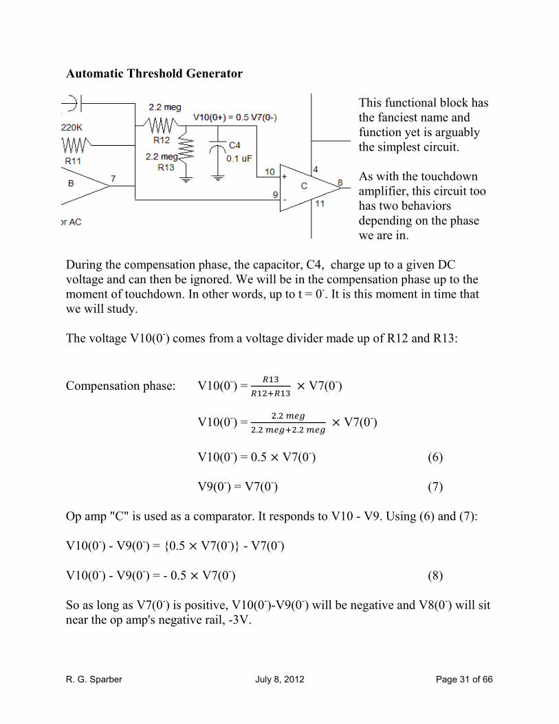
Automatic Threshold Generator
This functional block has
the fanciest name and
function yet is arguably
the simplest circuit.
As with the touchdown
amplifier, this circuit too
has two behaviors
depending on the phase
we are in.
During the compensation phase, the capacitor, C4, charge up to a given DC
voltage and can then be ignored. We will be in the compensation phase up to the
moment of touchdown. In other words, up to t = 0-. It is this moment in time that
we will study.
The voltage V10(0-) comes from a voltage divider made up of R12 and R13:
Compensation phase: V10(0-) =
�,����, × V7(0
-)
V10(0-) =
�.���-�.���-��.���- × V7(0
-)
V10(0-) = 0.5 × V7(0-) (6)
V9(0-) = V7(0
-) (7)
Op amp "C" is used as a comparator. It responds to V10 - V9. Using (6) and (7):
V10(0-) - V9(0
-) = {0.5 × V7(0-)} - V7(0-)
V10(0-) - V9(0
-) = - 0.5 × V7(0-) (8)
So as long as V7(0-) is positive, V10(0
-)-V9(0
-) will be negative and V8(0
-) will sit
near the op amp's negative rail, -3V.
R. G. Sparber July 8, 2012 Page 32 of 66
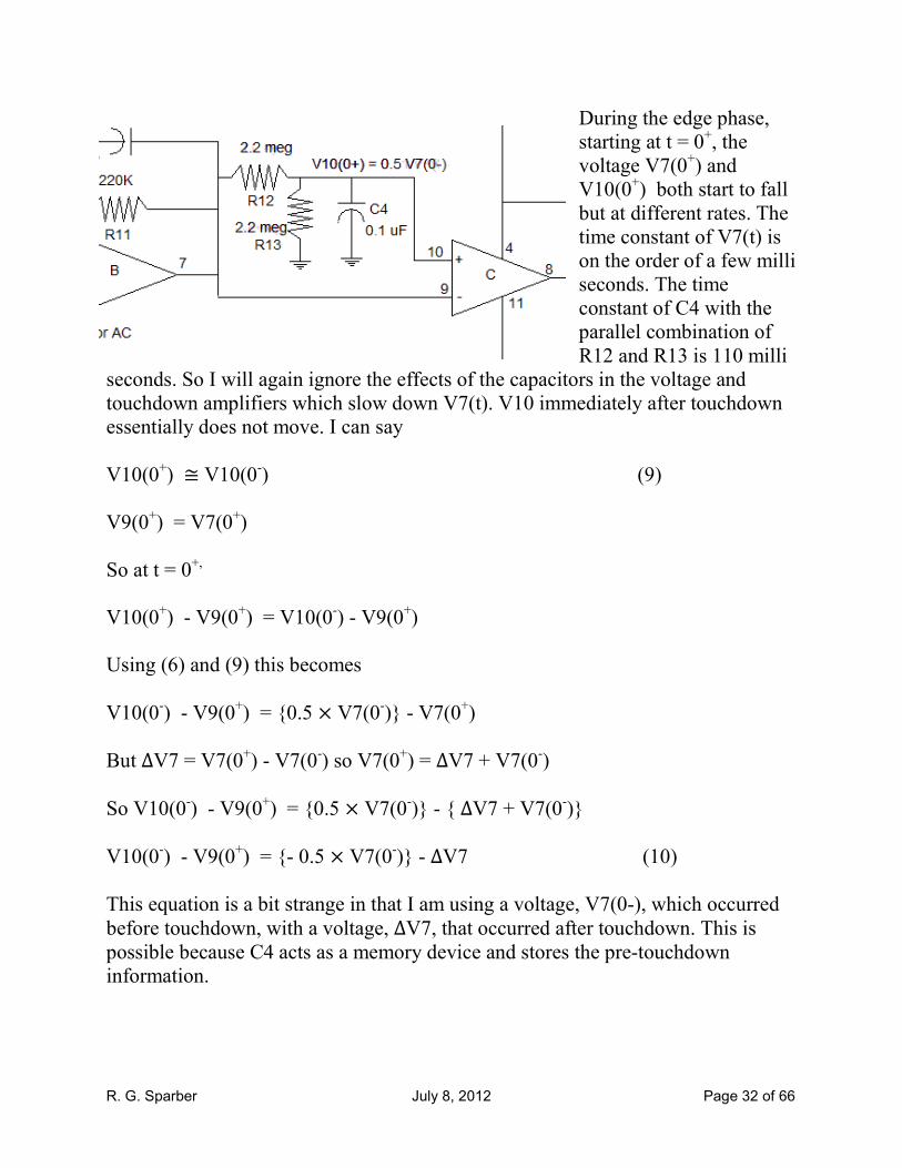
During the edge phase,
starting at t = 0+, the
voltage V7(0+) and
V10(0+) both start to fall
but at different rates. The
time constant of V7(t) is
on the order of a few milli
seconds. The time
constant of C4 with the
parallel combination of
R12 and R13 is 110 milli
seconds. So I will again ignore the effects of the capacitors in the voltage and
touchdown amplifiers which slow down V7(t). V10 immediately after touchdown
essentially does not move. I can say
V10(0+) ≅ V10(0-) (9)
V9(0+) = V7(0
+)
So at t = 0+,
V10(0+) - V9(0
+) = V10(0
-) - V9(0
+)
Using (6) and (9) this becomes
V10(0-) - V9(0
+) = {0.5 × V7(0-)} - V7(0+)
But ∆V7 = V7(0+) - V7(0-) so V7(0+) = ∆V7 + V7(0-)
So V10(0-) - V9(0
+) = {0.5 × V7(0-)} - { ∆V7 + V7(0-)}
V10(0-) - V9(0
+) = {- 0.5 × V7(0-)} - ∆V7 (10)
This equation is a bit strange in that I am using a voltage, V7(0-), which occurred
before touchdown, with a voltage, ∆V7, that occurred after touchdown. This is possible because C4 acts as a memory device and stores the pre-touchdown
information.
R. G. Sparber July 8, 2012 Page 33 of 66
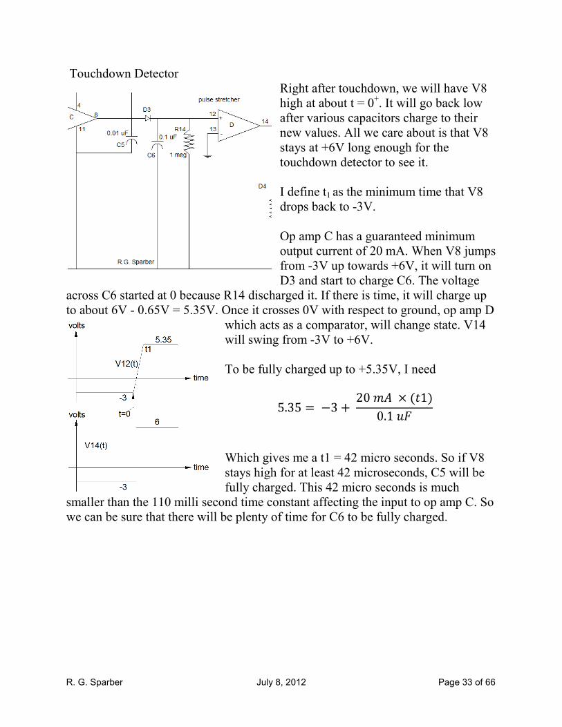
Touchdown Detector
Right after touchdown, we will have V8
high at about t = 0+. It will go back low
after various capacitors charge to their
new values. All we care about is that V8
stays at +6V long enough for the
touchdown detector to see it.
I define t1 as the minimum time that V8
drops back to -3V.
Op amp C has a guaranteed minimum
output current of 20 mA. When V8 jumps
from -3V up towards +6V, it will turn on
D3 and start to charge C6. The voltage
across C6 started at 0 because R14 discharged it. If there is time, it will charge up
to about 6V - 0.65V = 5.35V. Once it crosses 0V with respect to ground, op amp D
which acts as a comparator, will change state. V14
will swing from -3V to +6V.
To be fully charged up to +5.35V, I need
5.35 = −3 +2023 × (51)0.178
Which gives me a t1 = 42 micro seconds. So if V8
stays high for at least 42 microseconds, C5 will be
fully charged. This 42 micro seconds is much
smaller than the 110 milli second time constant affecting the input to op amp C. So
we can be sure that there will be plenty of time for C6 to be fully charged.
R. G. Sparber July 8, 2012 Page 34 of 66
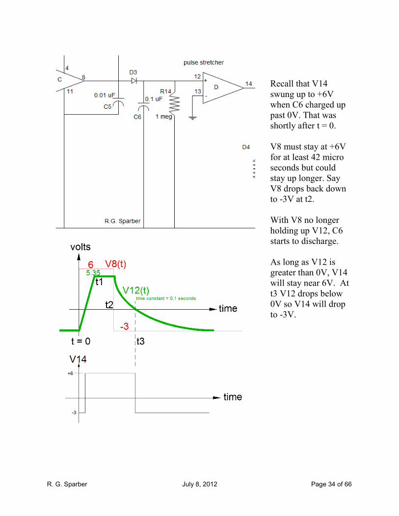
Recall that V14
swung up to +6V
when C6 charged up
past 0V. That was
shortly after t = 0.
V8 must stay at +6V
for at least 42 micro
seconds but could
stay up longer. Say
V8 drops back down
to -3V at t2.
With V8 no longer
holding up V12, C6
starts to discharge.
As long as V12 is
greater than 0V, V14
will stay near 6V. At
t3 V12 drops below
0V so V14 will drop
to -3V.
R. G. Sparber July 8, 2012 Page 35 of 66
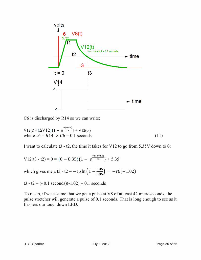
C6 is discharged by R14 so we can write:
V12(t) ={∆V12}{1 −:;(<;<=)>? } + V12(0-)
where @6 = �14 × &6 = 0.1 seconds (11)
I want to calculate t3 - t2, the time it takes for V12 to go from 5.35V down to 0:
V12(t3 - t2) = 0 = {0 − 8.35}{1 −:;(<D;<=)
>? } + 5.35
which gives me a t3 - t2 = −@6 ln G1 − �.,� .,�H = −@6(−1.02)
t3 - t2 = (- 0.1 seconds)(-1.02) = 0.1 seconds
To recap, if we assume that we get a pulse at V8 of at least 42 microseconds, the
pulse stretcher will generate a pulse of 0.1 seconds. That is long enough to see as it
flashers our touchdown LED.

R. G. Sparber July 8, 2012 Page 36 of 66
Touchdown LED
When the output of op amp D is at -3V, there is no voltage
across the touchdown LED or its current limiting resistor,
R15. But during the time from t2 to t3, V14 is at 6V so the
voltage across R15 is at 6V - VD4 - (-3). D4 drops
approximately 3V so R15 has about 6V across it. Since it is
1K, this means that the current through it is about 6 mA.
This current also flows through D4 which is a Super Bright
LED. The 0.1 second flash of light from D4 is easy to see.
R. G. Sparber July 8, 2012 Page 37 of 66
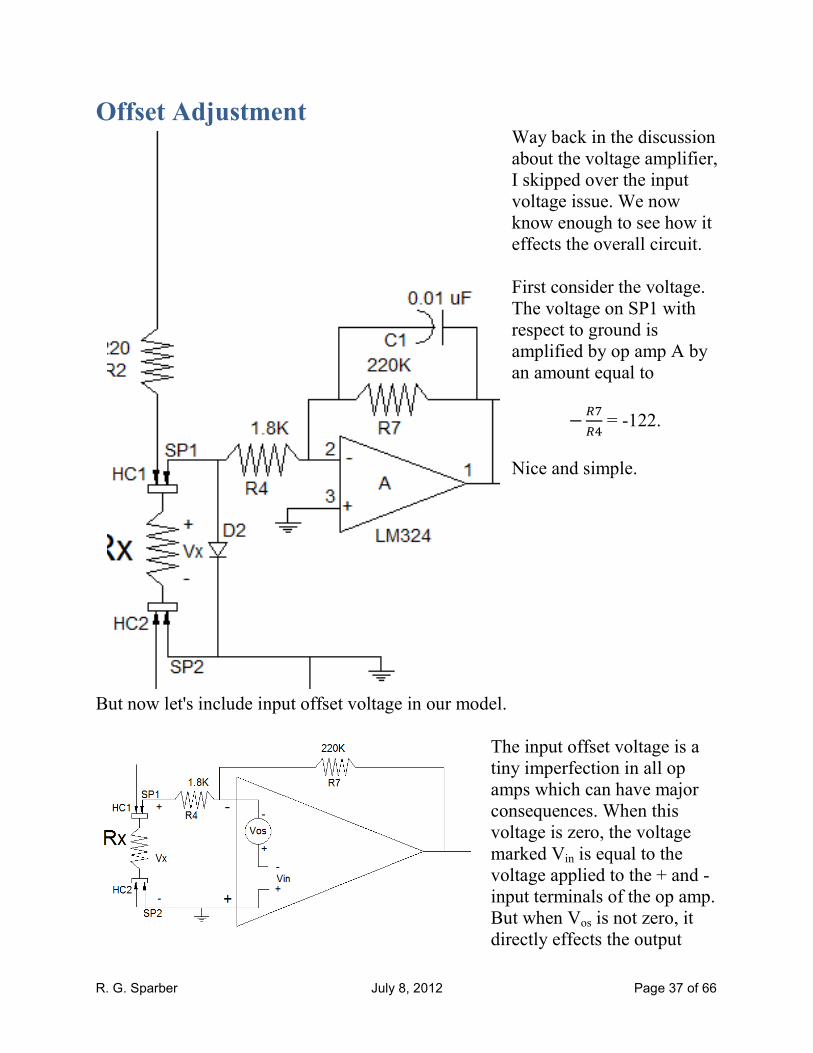
Offset Adjustment Way back in the discussion
about the voltage amplifier,
I skipped over the input
voltage issue. We now
know enough to see how it
effects the overall circuit.
First consider the voltage.
The voltage on SP1 with
respect to ground is
amplified by op amp A by
an amount equal to
− ���� = -122.
Nice and simple.
But now let's include input offset voltage in our model.
The input offset voltage is a
tiny imperfection in all op
amps which can have major
consequences. When this
voltage is zero, the voltage
marked Vin is equal to the
voltage applied to the + and -
input terminals of the op amp.
But when Vos is not zero, it
directly effects the output
R. G. Sparber July 8, 2012 Page 38 of 66
voltage. The polarity of Vos
cannot be controlled by the
manufacturer but they can
specify a maximum
magnitude. For the LM324, it
is 9 millivolts.
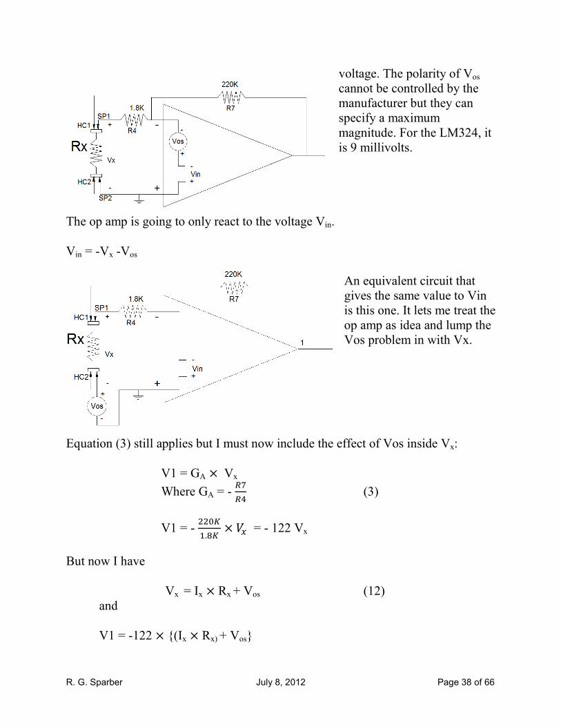
The op amp is going to only react to the voltage Vin.
Vin = -Vx -Vos
An equivalent circuit that
gives the same value to Vin
is this one. It lets me treat the
op amp as idea and lump the
Vos problem in with Vx.
Equation (3) still applies but I must now include the effect of Vos inside Vx:
V1 = GA × Vx
Where GA = - ���� (3)
V1 = - ����. � × �� = - 122 Vx
But now I have
Vx = Ix × Rx + Vos (12) and
V1 = -122 × {(Ix × Rx) + Vos}
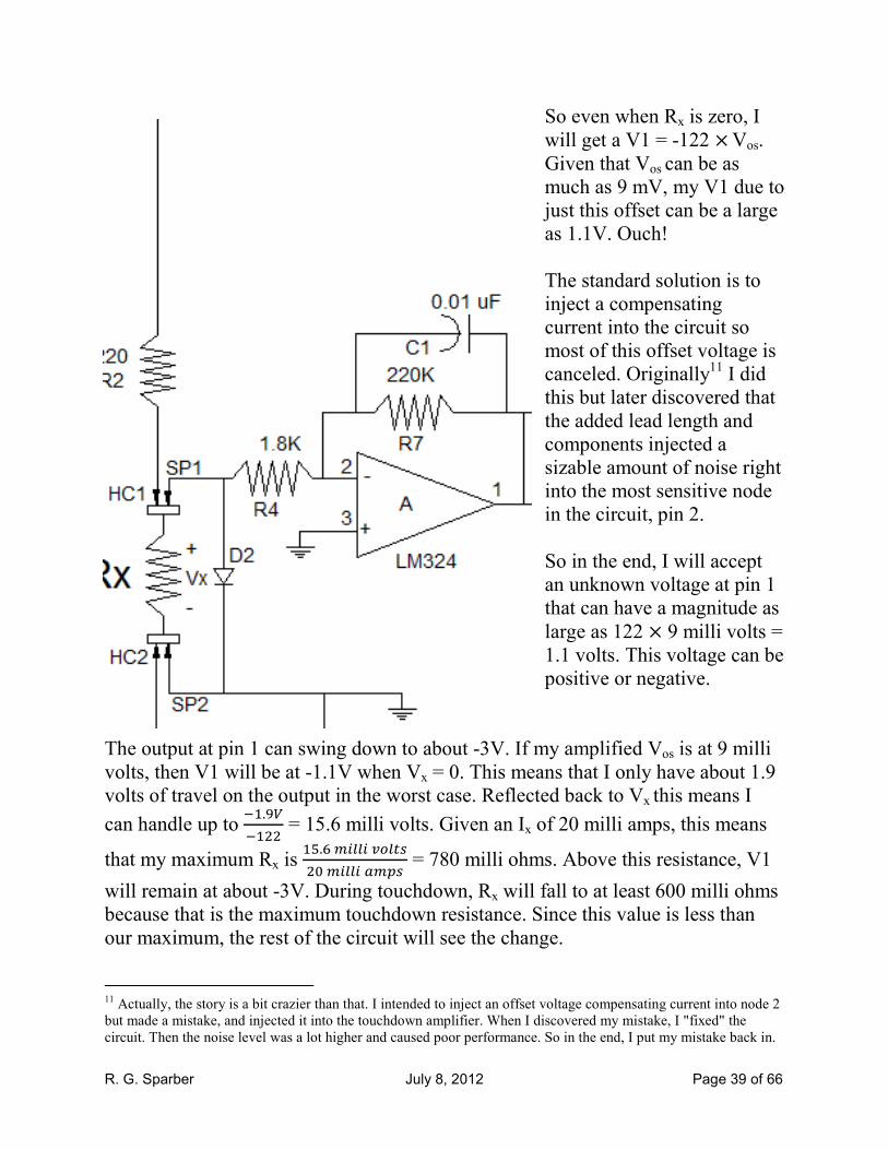
R. G. Sparber July 8, 2012 Page 39 of 66
So even when Rx is zero, I
will get a V1 = -122 × Vos.
Given that Vos can be as
much as 9 mV, my V1 due to
just this offset can be a large
as 1.1V. Ouch!
The standard solution is to
inject a compensating
current into the circuit so
most of this offset voltage is
canceled. Originally11 I did
this but later discovered that
the added lead length and
components injected a
sizable amount of noise right
into the most sensitive node
in the circuit, pin 2.
So in the end, I will accept
an unknown voltage at pin 1
that can have a magnitude as
large as 122 × 9 milli volts =
1.1 volts. This voltage can be
positive or negative.
The output at pin 1 can swing down to about -3V. If my amplified Vos is at 9 milli
volts, then V1 will be at -1.1V when Vx = 0. This means that I only have about 1.9
volts of travel on the output in the worst case. Reflected back to Vx this means I
can handle up to �.(���� = 15.6 milli volts. Given an Ix of 20 milli amps, this means
that my maximum Rx is �. �IJJIK�J�����IJJI��L� = 780 milli ohms. Above this resistance, V1
will remain at about -3V. During touchdown, Rx will fall to at least 600 milli ohms
because that is the maximum touchdown resistance. Since this value is less than
our maximum, the rest of the circuit will see the change.
11 Actually, the story is a bit crazier than that. I intended to inject an offset voltage compensating current into node 2
but made a mistake, and injected it into the touchdown amplifier. When I discovered my mistake, I "fixed" the
circuit. Then the noise level was a lot higher and caused poor performance. So in the end, I put my mistake back in.
R. G. Sparber July 8, 2012 Page 40 of 66
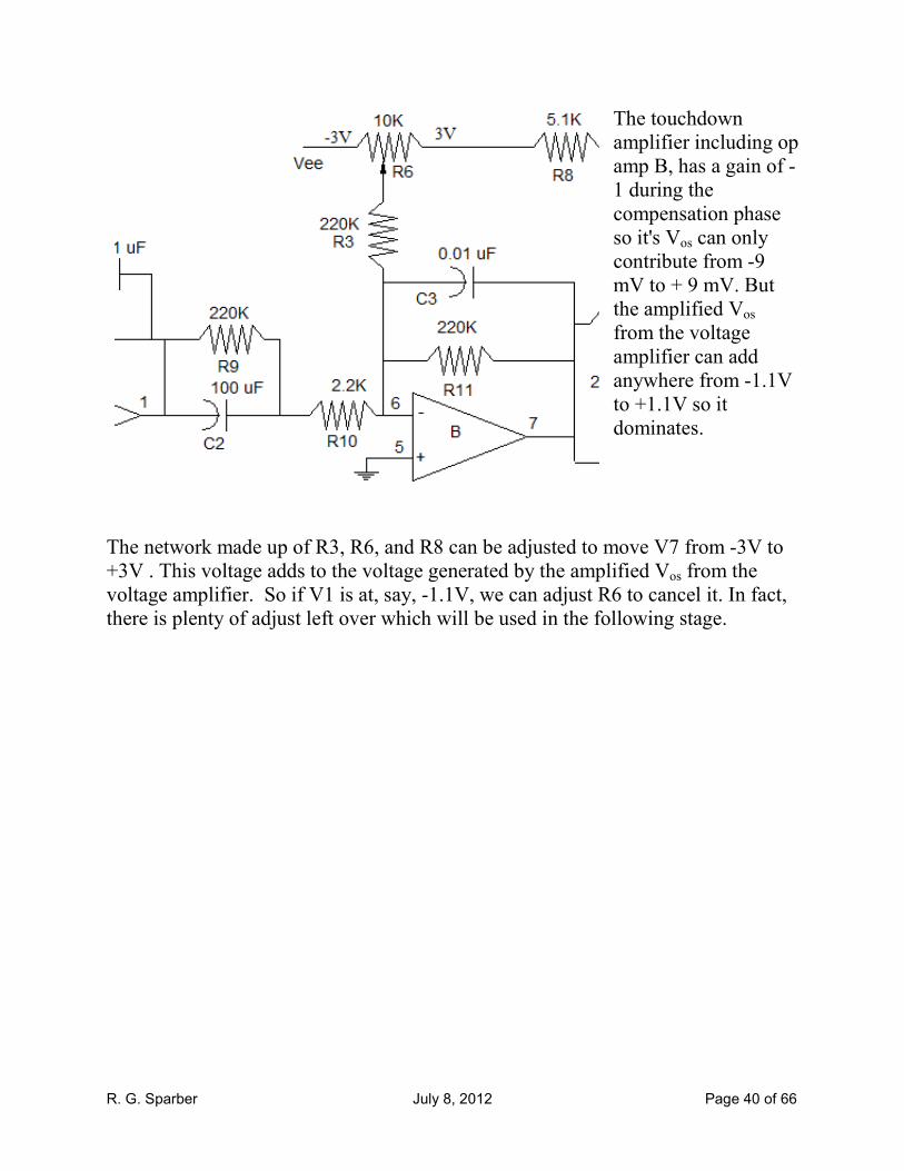
The touchdown
amplifier including op
amp B, has a gain of -
1 during the
compensation phase
so it's Vos can only
contribute from -9
mV to + 9 mV. But
the amplified Vos
from the voltage
amplifier can add
anywhere from -1.1V
to +1.1V so it
dominates.
The network made up of R3, R6, and R8 can be adjusted to move V7 from -3V to
+3V . This voltage adds to the voltage generated by the amplified Vos from the
voltage amplifier. So if V1 is at, say, -1.1V, we can adjust R6 to cancel it. In fact,
there is plenty of adjust left over which will be used in the following stage.
R. G. Sparber July 8, 2012 Page 41 of 66
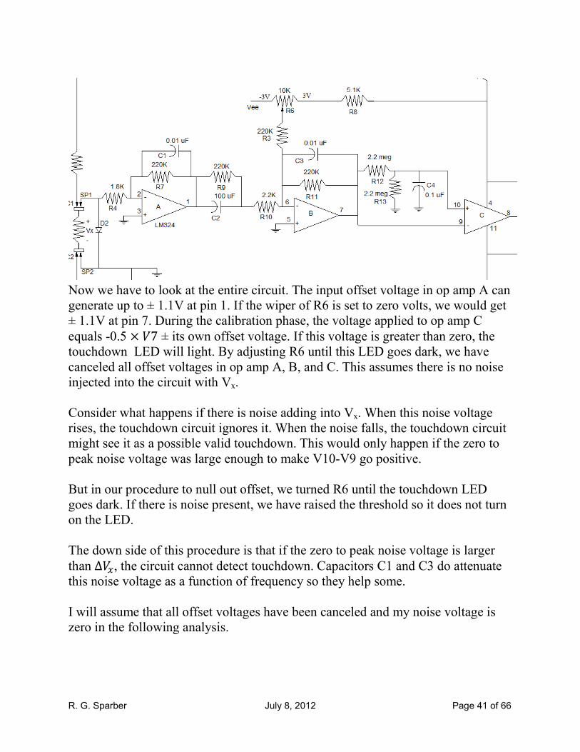
Now we have to look at the entire circuit. The input offset voltage in op amp A can
generate up to ± 1.1V at pin 1. If the wiper of R6 is set to zero volts, we would get
± 1.1V at pin 7. During the calibration phase, the voltage applied to op amp C
equals -0.5 × �7 ± its own offset voltage. If this voltage is greater than zero, the touchdown LED will light. By adjusting R6 until this LED goes dark, we have
canceled all offset voltages in op amp A, B, and C. This assumes there is no noise
injected into the circuit with Vx.
Consider what happens if there is noise adding into Vx. When this noise voltage
rises, the touchdown circuit ignores it. When the noise falls, the touchdown circuit
might see it as a possible valid touchdown. This would only happen if the zero to
peak noise voltage was large enough to make V10-V9 go positive.
But in our procedure to null out offset, we turned R6 until the touchdown LED
goes dark. If there is noise present, we have raised the threshold so it does not turn
on the LED.
The down side of this procedure is that if the zero to peak noise voltage is larger
than ∆��, the circuit cannot detect touchdown. Capacitors C1 and C3 do attenuate this noise voltage as a function of frequency so they help some.
I will assume that all offset voltages have been canceled and my noise voltage is
zero in the following analysis.

R. G. Sparber July 8, 2012 Page 42 of 66
The Calibration Phase We now have all of the equations necessary to define the calibration phase. This
assumes you have nulled out all input offset voltages via R6 and the procedure
defined in the last page plus that no electrical noise exists. Let me collect my
equations first.
Vx = Rx × Ix (2)
V1 = GA × Vx
Where GA = - ���� (3)
V1 = - ����. � × �� = - 122 Vx
V7 = - �
�(��� × �1
V7= - ����
������.�� × �1 ≅ -V1 (4)
Note that V7 during the calibration phase equals V7(0-) to be used during the
touchdown phase.
Next I will combine equations:
V7(0-) = V7
V7(0-) = -V1
V7(0-) = 122Vx
V7(0-) = 122 × Rx × Ix (13)
This equation tells us the voltage applied to the touchdown detector given Rx and
Ix. The limiting case is for the smallest Rx which is 0.01 ohms. Assuming an Ix of
20 mA,
V7(0-) = 122 × 0.01 ohms × 20 mA
V7(0-) = 24.4 milli volts
R. G. Sparber July 8, 2012 Page 43 of 66
We have
V10(0-) - V9(0
-) = - 0.5 × V7(0-) (8)
so
V10(0-) - V9(0
-) = - 0.5 × 24.4 milli volts
V10(0-) - V9(0
-) = - 12.2 milli volts
This says that at our smallest Rx, op amp C's input is sitting at -12.2 milli volts so
its output is at -3V.
For the selected resistor values,
V10(0-) - V9(0
-) = -61 × Rx × Ix
V10(0-) - V9(0
-) = -61 × Rx × 20 mA
V10(0-) - V9(0
-) = -1.22 amps × Rx (8a)
where Rx is in ohms.
In the general case,
V10(0-) - V9(0
-) = - (
���×��) × (1amp) × Rx (8b)
where Rx is in ohms.
R. G. Sparber July 8, 2012 Page 44 of 66
The Touchdown Phase I will again start by collecting equations.
∆Vx = ∆Rx × Ix (∆2)
∆V1 = GA × ∆Vx
Where GA = - ����
∆V1 = - ����. � × �� = - 122 ∆Vx (∆3)
∆V7 = - ��� × ∆�1
∆V7= - �����.�� × �1 = -100∆V1 (4)
V7(0-) = 122 × Rx × Ix (13)
V10(0-) - V9(0
+) = {- 0.5 × V7(0-)} - ∆V7 (10)
Next I will combine equations:
V10(0-) - V9(0
+) = {- 0.5 × V7(0-)} - ∆V7 (10)
V10(0-) - V9(0
+) = {-0.5 × [122 × Rx × Ix]} - {-100∆V1}
V10(0-) - V9(0
+) = {-0.5 × [122 × Rx × Ix]} - {-100 × (-122∆Vx)}
V10(0-) - V9(0
+) = {-0.5 × [122 × Rx × Ix]} - {-100 × (-122 × ∆Rx × Ix}
For the selected resistor values,
V10(0-) - V9(0
+) = Ix × {(-61 × Rx) - (12,200 × ∆Rx)} (14)
Where Ix is in amps and all resistance is in ohms.
R. G. Sparber July 8, 2012 Page 45 of 66
In the general case,
V10(0-) - V9(0
+) = -Ix × {[( ��
�×��) × Rx] + [(��×���×��) × ∆Rx]} (14a)
Where Ix is in amps and all resistance is in ohms.
This equation tells us the voltage change at op amp C given Rx and ∆Rx . The
limiting case is for the smallest Rx which is 0.01 ohms and the corresponding
smallest ∆Rx which is -164 micro ohms.
V10(0-) - V9(0
+) = Ix × {(- 61 × Rx) - (12,200 × ∆Rx)} (14)
V10(0-) - V9(0
+) = Ix × {(-61 × 0.01 ohms) - (12,200 × [−164microohms])}
V10(0-) - V9(0
+) = Ix × {-0.610 ohms + 2.00 ohms}
V10(0-) - V9(0
+) = Ix × {1.39 ohms}
Given an Ix of 20 mA,
V10(0-) - V9(0
+) = 27.8 milli volts
Let's stop and reflect on all of this math. Given the smallest expected Rx of 0.01
ohms and a ∆Rx of -164 micro ohms, op amp C's input will be at -12.2 milli volts
before touchdown and + 27.8 milli volts after touchdown. This transition will
easily cause op amp C to change from outputting -3V to +6V.

R. G. Sparber July 8, 2012 Page 46 of 66
The Effect of Unwanted Electrical Noise
All of the calculations so far have assumed that there is no electrical noise mixing
in with Vx. Although C1 and C3 tend to reduce this noise, some will still be there.
This noise will erode our overdrive margins.
Starting at the left, I have Vxac. I have assumed it is sinusoidal and at a frequency
that is far below the corner frequencies of the two voltage amplifiers. This is my
worst case.
Since this noise is AC, it will be multiplied by 122 in the voltage amplifier and by
100 in the touchdown amplifier.
The amplified noise then goes straight into
the inverting input of op amp C.
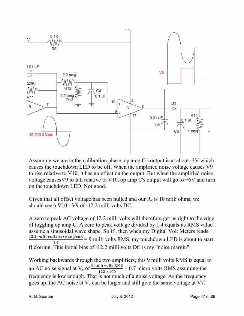
R. G. Sparber July 8, 2012 Page 47 of 66
Assuming we are in the calibration phase, op amp C's output is at about -3V which
causes the touchdown LED to be off. When the amplified noise voltage causes V9
to rise relative to V10, it has no effect on the output. But when the amplified noise
voltage causesV9 to fall relative to V10, op amp C's output will go to +6V and turn
on the touchdown LED. Not good.
Given that all offset voltage has been nulled and our Rx is 10 milli ohms, we
should see a V10 - V9 of -12.2 milli volts DC.
A zero to peak AC voltage of 12.2 milli volts will therefore get us right to the edge
of toggling op amp C. A zero to peak voltage divided by 1.4 equals its RMS value
assume a sinusoidal wave shape. So if , then when my Digital Volt Meters reads �.��IJJIK�J��V�����L��W
.� = 9 milli volts RMS, my touchdown LED is about to start
flickering. This initial bias of -12.2 milli volts DC is my "noise margin".
Working backwards through the two amplifiers, this 9 milli volts RMS is equal to
an AC noise signal at Vx of (XYZZY[\Z]^_`a
���� = 0.7 micro volts RMS assuming the
frequency is low enough. That is not much of a noise voltage. As the frequency
goes up, the AC noise at Vx can be larger and still give the same voltage at V7.
R. G. Sparber July 8, 2012 Page 48 of 66
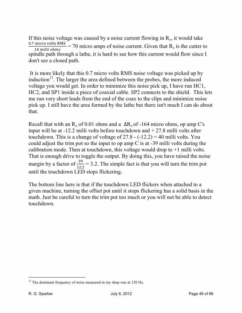
If this noise voltage was caused by a noise current flowing in Rx, it would take �.�XYbc\[\Z]^_`a
��IJJI���� = 70 micro amps of noise current. Given that Rx is the cutter to
spindle path through a lathe, it is hard to see how this current would flow since I
don't see a closed path.
It is more likely that this 0.7 micro volts RMS noise voltage was picked up by
induction12. The larger the area defined between the probes, the more induced
voltage you would get. In order to minimize this noise pick up, I have run HC1,
HC2, and SP1 inside a piece of coaxial cable. SP2 connects to the shield. This lets
me run very short leads from the end of the coax to the clips and minimize noise
pick up. I still have the area formed by the lathe but there isn't much I can do about
that.
Recall that with an Rx of 0.01 ohms and a ∆Rx of -164 micro ohms, op amp C's
input will be at -12.2 milli volts before touchdown and + 27.8 milli volts after
touchdown. This is a change of voltage of 27.8 - (-12.2) = 40 milli volts. You
could adjust the trim pot so the input to op amp C is at -39 milli volts during the
calibration mode. Then at touchdown, this voltage would drop to +1 milli volts.
That is enough drive to toggle the output. By doing this, you have raised the noise
margin by a factor of ,(�.� = 3.2. The simple fact is that you will turn the trim pot
until the touchdown LED stops flickering.
The bottom line here is that if the touchdown LED flickers when attached to a
given machine, turning the offset pot until it stops flickering has a solid basis in the
math. Just be careful to turn the trim pot too much or you will not be able to detect
touchdown.
12 The dominant frequency of noise measured in my shop was at 120 Hz.
R. G. Sparber July 8, 2012 Page 49 of 66
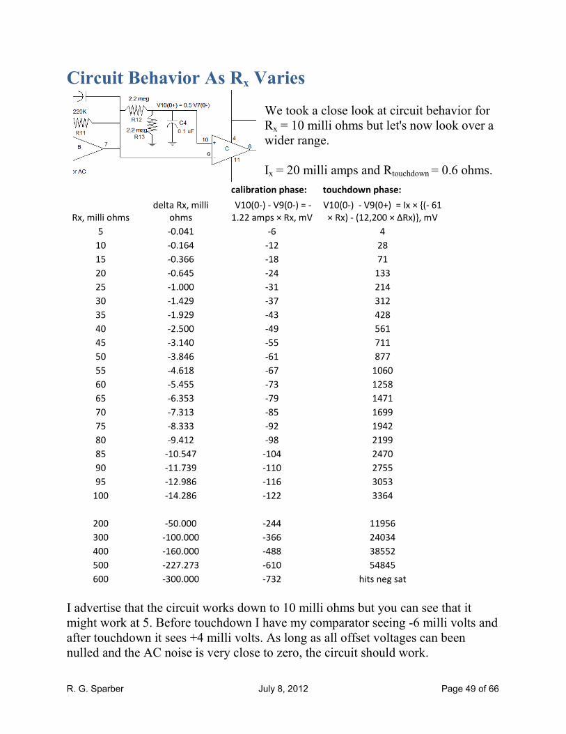
Circuit Behavior As Rx Varies
We took a close look at circuit behavior for
Rx = 10 milli ohms but let's now look over a
wider range.
Ix = 20 milli amps and Rtouchdown = 0.6 ohms.
calibration phase: touchdown phase:
Rx, milli ohms
delta Rx, milli
ohms
V10(0-) - V9(0-) = -
1.22 amps × Rx, mV
V10(0-) - V9(0+) = Ix × {(- 61
× Rx) - (12,200 × ∆Rx)}, mV
5 -0.041 -6 4
10 -0.164 -12 28
15 -0.366 -18 71
20 -0.645 -24 133
25 -1.000 -31 214
30 -1.429 -37 312
35 -1.929 -43 428
40 -2.500 -49 561
45 -3.140 -55 711
50 -3.846 -61 877
55 -4.618 -67 1060
60 -5.455 -73 1258
65 -6.353 -79 1471
70 -7.313 -85 1699
75 -8.333 -92 1942
80 -9.412 -98 2199
85 -10.547 -104 2470
90 -11.739 -110 2755
95 -12.986 -116 3053
100 -14.286 -122 3364
200 -50.000 -244 11956
300 -100.000 -366 24034
400 -160.000 -488 38552
500 -227.273 -610 54845
600 -300.000 -732 hits neg sat
I advertise that the circuit works down to 10 milli ohms but you can see that it
might work at 5. Before touchdown I have my comparator seeing -6 milli volts and
after touchdown it sees +4 milli volts. As long as all offset voltages can been
nulled and the AC noise is very close to zero, the circuit should work.
R. G. Sparber July 8, 2012 Page 50 of 66
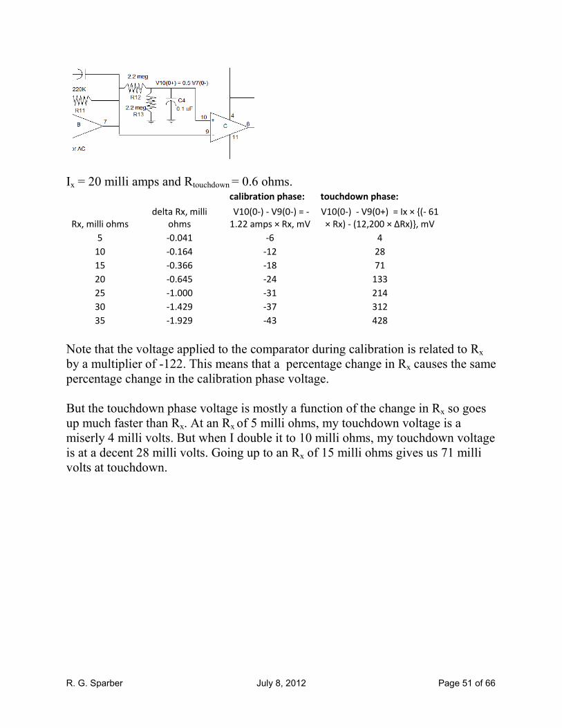
Ix = 20 milli amps and Rtouchdown = 0.6 ohms.
calibration phase: touchdown phase:
Rx, milli ohms delta Rx, milli ohms
V10(0-) - V9(0-) = -
1.22 amps × Rx, mV
V10(0-) - V9(0+) = Ix × {(- 61 ×
Rx) - (12,200 × ∆Rx)}, mV
5 -0.041 -6 4
This case has the smallest drive to the comparator13 but was not the point where the
circuit was designed. That was done at 10 milli ohms. At larger values of Rx, all
voltages are larger so the absolute values of the voltages is not as important.
I thought it was interesting to see that if I change Rtouchdown from 0.6 ohms down to
0.5 ohms, then the comparator sees -6 mV before touchdown and + 6 mV after
touchdown. Nice and symmetric but due to a very tiny change.
This tells me that it is not worth playing with the circuit just to get this symmetry.
Ix = 20 milli amps and Rtouchdown = 0.5 ohms.
calibration phase: touchdown phase:
Rx, milli ohms
delta Rx, milli
ohms
V10(0-) - V9(0-) = -
1.22 amps × Rx, mV
V10(0-) - V9(0+) = Ix × {(- 61
× Rx) - (12,200 × ∆Rx)}, mV
5 -0.050 -6 6
13 The op amp swings from about -3 to +6V. Typical gain is 100 dB which equals a voltage gain of 10
5. This means
that 90 micro volts at its input is enough to move the output from -3V to +6V. So even 4 milli volts is plenty of
drive.
R. G. Sparber July 8, 2012 Page 51 of 66
Ix = 20 milli amps and Rtouchdown = 0.6 ohms.
calibration phase: touchdown phase:
Rx, milli ohms
delta Rx, milli
ohms
V10(0-) - V9(0-) = -
1.22 amps × Rx, mV
V10(0-) - V9(0+) = Ix × {(- 61
× Rx) - (12,200 × ∆Rx)}, mV
5 -0.041 -6 4
10 -0.164 -12 28
15 -0.366 -18 71
20 -0.645 -24 133
25 -1.000 -31 214
30 -1.429 -37 312
35 -1.929 -43 428
Note that the voltage applied to the comparator during calibration is related to Rx
by a multiplier of -122. This means that a percentage change in Rx causes the same
percentage change in the calibration phase voltage.
But the touchdown phase voltage is mostly a function of the change in Rx so goes
up much faster than Rx. At an Rx of 5 milli ohms, my touchdown voltage is a
miserly 4 milli volts. But when I double it to 10 milli ohms, my touchdown voltage
is at a decent 28 milli volts. Going up to an Rx of 15 milli ohms gives us 71 milli
volts at touchdown.
R. G. Sparber July 8, 2012 Page 52 of 66
A Peak Into the Design Process
So far, you have seen just the answer. For some, this can be rather frustrating since
there is no hint as to how we got here. Why this topology? Why these values?
In this section, I hope to share some of the messy process. I will spare you most of
the false starts.
The brute force technique of applying a BIG current to a small resistance to
generate a reasonably large voltage generated a lot of concern over damaging
bearings inside the machine. Applying a small current to this small resistance
generated a voltage that was difficult to see given the unknown offset voltage of
each op amp. This offset voltage multiplied by the needed gain produced an output
voltage large enough to saturate the final gain stage. So that was a bust.
But then it occurred to me that I really only cared about the change in Rx and not
its absolute value. The change was abrupt so contained a lot of AC components.
Why not have a low gain for Rx and a high gain for the change in Rx?
I wanted to have a test current, Ix, of 10 mA because it seemed very safe for
bearings plus a minimum Rx of 5 milli ohms. I advertise a minimum of 10 milli
ohms but wanted so margin.
Given a touchdown resistance of 0.6 ohms, this gave me a ∆Rx of -41.3 micro
ohms. I assumed my comparator would need -10 milli volts of bias to stay in the
low state. I would then give it a 20 milli volts step to get it to a bias of +10 milli
volts. That would change its output to the high state and indicate touchdown.
So now I had all of the pieces: ∆Rx is -41.3 micro ohms, Ix = 10 milli amps, and
∆V at the comparator of 10 milli volts:
∆� = d�e × ∆�f × gf
So Gac = ���IJJIK�J��
(�.,XYbc\\hX^�XYZZYiXj^) = 48,430
Assuming two gain stages, this meant that each stage had to have a gain of 220.
That seemed kind of high. I doubled my test current to 20 milli amps and lowered
my comparator bias to 5 milli volts:
R. G. Sparber July 8, 2012 Page 53 of 66
So Gac = ��IJJIK�J��
(�.,XYbc\\hX^��XYZZYiXj^) = 12,110
This can be done by two stages, each with a gain of 110.
Assuming a simple inverting amplifier, I liked having a feedback resistor of 220K
which meant that the input resistor would need to be 2K. My junk box didn't have
any of those. I had 1.8K and 2.2K. Using 1.8K, my gain was -122. Using 2.2K my
gain was -100. Hmm. The overall gain came out to 12,200. So that worked OK.
So now I had the gain correct for amplifying the change in voltage related to a
change in Rx. At first I used a potentiometer to adjust the threshold of the
comparator but that was a real pain. Could I do this automatically?
After a bit of thought, I realized that Rx and ∆Rx are related. Could I use Rx to set
the threshold? This would be most critical at minimum Rx so that is where I
focused my design. After a few false starts, I came to the circuit I call my
automatic threshold generator (see page31). It takes the amplified voltage
generated across Rx before touchdown and stores it on a capacitor. Then when
touchdown comes, it lets the change in voltage pass through to the inverting input
of the comparator. I will not repeat the math here, but the result is that my
threshold is proportional to Rx and my transition is proportional to the change in
Rx. The calibration voltage out of my second gain stage had to be twice the needed
bias due to the voltage divider formed by R12 and R13.
By this time I had also decided to try and use a simple inverting voltage amplifier
for the first stage and a high pass amplifier for the second state. This second stage
would have a gain of -1 at DC and a higher gain at AC when the change in input
voltage came through at touchdown.
I still needed to decide how much of this gain to use to amplify the voltage across
Rx during calibration.
With an Rx of 5 milli ohms and a test current of 20 milli amps, I get a voltage of
100 micro volts. I have already decided that I wanted an initial bias on the
comparator of 5 milli volts which translates to a voltage out of the second gain
stage of 10 milli volts. Call this voltage V7. This told me that my DC gain had to
be
�7 = d�e × �f �7 = d�e × �f × gf
102kllkmnl5o = d�e × 52kllknℎ2o × 202kllkq2ro
R. G. Sparber July 8, 2012 Page 54 of 66
So Gdc = ��IJJIK�J��
��IJJI�������IJJI��L� = 100 . This is the gain of my first voltage
amplifier.
Gac = 12,110 which equals the gain of my first amplifier times the gain of my
second amplifier. But the first amplifier's gain is just Gdc so my second amplifier
must be �,��� = 121.
You may notice that I chose to have the first amplifier set to 122 and the second
amplifier set to 100. My Gac is about right but my Gdc is a bit high. I did this for
two reasons. I wanted the time constant formed from C2 and R10 to be as large as
possible. Using an R10 of 2.2K was therefore a little better than using the value of
1.8K. The second reason had to do with noise margin. The slightly higher DC gain
set my calibration phase bias of op amp C a little higher than if Gdc was 100. That
gives me a 22% increase in noise margin at my 5 milli ohm level.
After some testing in a shop with commercial grade machines, I decided to add
feedback capacitors to reduce the sensitivity to noise.
The pulse stretcher was added because I wanted to insure a minimum time the
touchdown LED would be on. I also had a spare op amp just screaming to be used.
I then turned to human factors concerns. In my shop, I really hate having to
remember to turn battery powered devices off. So the circuit had to automatically
power up when used and power down when put away. Well worth the single
resistor and single transistor to do this function. I also wanted a power on indicator
but didn't want to waste any current on it. By putting it in series with Rx, I got to
use an existing current. This LED also gave me a voltage, Vee, that was about 3V
below ground. That enabled the first gain stage output to swing below ground to
almost -3V.
Going with the Kelvin connection solved two problems. It eliminated
uncontrollable voltage drops in the probes which could obscure the voltage I was
trying to measure. It also let me completely disconnect HC1 from the rest of the
circuit to insure no leakage currents could flow. This current could partially turn on
power and run down the battery.
I have not fully explained why or how I chose this topology. It was not my first
choice but evolved as I saw trouble with the previous design. Parts, like the

R. G. Sparber July 8, 2012 Page 55 of 66
feedback capacitors, were added based on field experience. But most came from
just thinking about how it should work.
One word about component values. I tried my best to minimize the number of
different values. This should make buying parts a little easier.
R. G. Sparber July 8, 2012 Page 56 of 66
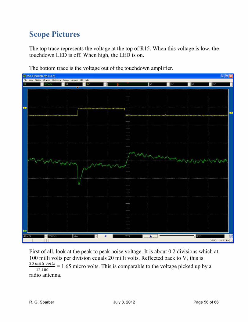
Scope Pictures
The top trace represents the voltage at the top of R15. When this voltage is low, the
touchdown LED is off. When high, the LED is on.
The bottom trace is the voltage out of the touchdown amplifier.
First of all, look at the peak to peak noise voltage. It is about 0.2 divisions which at
100 milli volts per division equals 20 milli volts. Reflected back to Vx this is ���IJJIK�J��
�,�� = 1.65 micro volts. This is comparable to the voltage picked up by a
radio antenna.
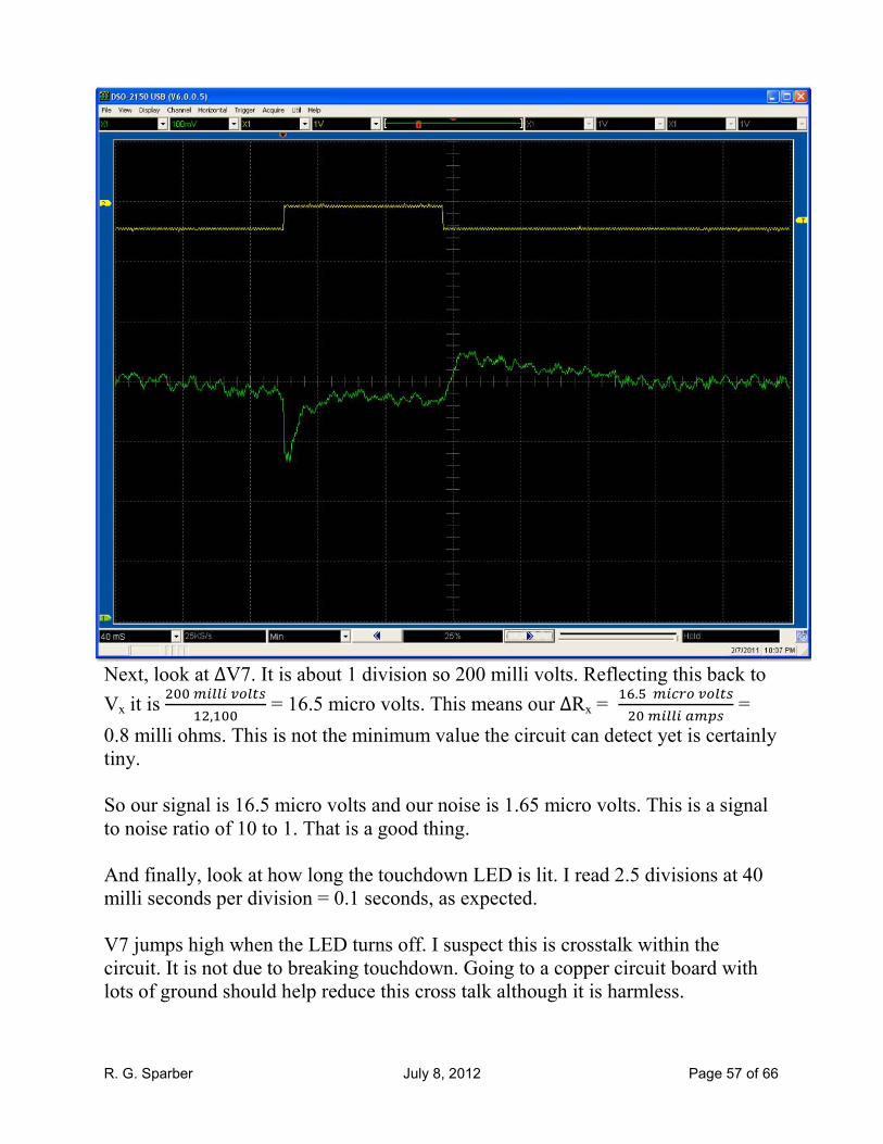
R. G. Sparber July 8, 2012 Page 57 of 66
Next, look at ∆V7. It is about 1 division so 200 milli volts. Reflecting this back to
Vx it is ����IJJIK�J��
�,�� = 16.5 micro volts. This means our ∆Rx = .��Ie��K�J�����IJJI��L� =
0.8 milli ohms. This is not the minimum value the circuit can detect yet is certainly
tiny.
So our signal is 16.5 micro volts and our noise is 1.65 micro volts. This is a signal
to noise ratio of 10 to 1. That is a good thing.
And finally, look at how long the touchdown LED is lit. I read 2.5 divisions at 40
milli seconds per division = 0.1 seconds, as expected.
V7 jumps high when the LED turns off. I suspect this is crosstalk within the
circuit. It is not due to breaking touchdown. Going to a copper circuit board with
lots of ground should help reduce this cross talk although it is harmless.

R. G. Sparber July 8, 2012 Page 58 of 66
My scope has the ability to do a Fast Fourier Transform of the signal. It shows that
most of the noise is the second harmonic of 60 Hz. Recall that both of the voltage
amplifiers have a corner frequency of 72 Hz so this 122.5 Hz has already been
attenuated by more than half.

R. G. Sparber July 8, 2012 Page 59 of 66
PSpice 9.1 Simulation
With the PSpice version 9.1 simulator I was able to see the minimum width of the
pulse out of the touchdown detector. I used the minimum Vx and ∆Vx. The time
that V10 - V9 is greater than 0V is more than 0.5 seconds. So we have no problem
meeting our need of having it high for more than 42 micro seconds as was assumed
on page 59.
Due to excessive input bias currents in the simulated op amps, I had to drop my
R12 and R13 values by a factor of 1000. I compensated by raising C4 by the same
factor.

R. G. Sparber July 8, 2012 Page 60 of 66
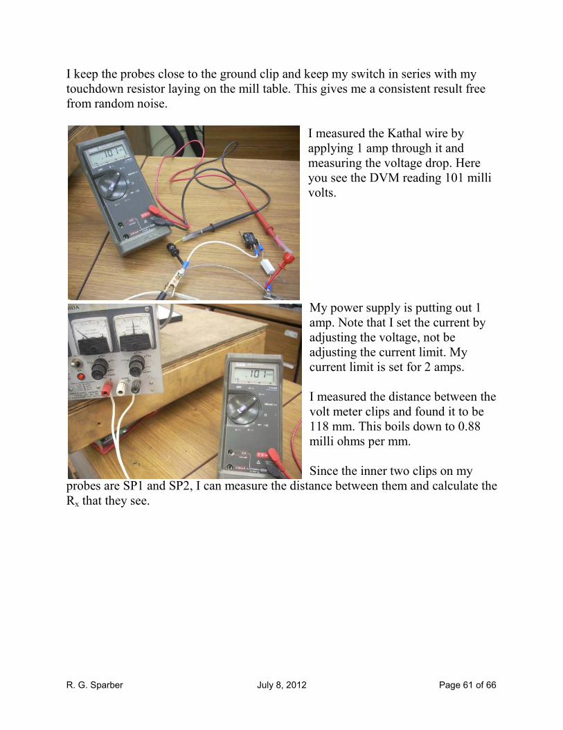
The Test Bed
Nothing will drive you crazy faster than inconsistent results. I learned early on to
set up a test bed for assessing the circuit's behavior that had minimum noise. I
chose the table of my mill.
I use a piece of Kathal
® wire as my variable Rx. One end is bolted to a steel plate
which is clamped to the table. This provides a minimal and consistent noise level. I
can't read the noise on the wire directly but by monitoring V7 with my meter set to
AC RMS, I do get a relative sense. You see here that the meter reads 4 milli volts
AC RMS. If I touch the grounded end of the wire, the reading does not change. If I
touch the far end of the Kathal wire, I see a jump of about 50 milli volts RMS and
the touchdown LED flashes.
If I take the meter reading as accurate, then this translates to a voltage at the probes
of ��IJJIK�J��t#�uv
�,��� = 0.3 micro volts. That 50 milli volts RMS reading translates
to a probe voltage of 4 micro volts. So it should not be a surprise that the circuit
has trouble in a noisy environment.
R. G. Sparber July 8, 2012 Page 61 of 66
I keep the probes close to the ground clip and keep my switch in series with my
touchdown resistor laying on the mill table. This gives me a consistent result free
from random noise.
I measured the Kathal wire by
applying 1 amp through it and
measuring the voltage drop. Here
you see the DVM reading 101 milli
volts.
My power supply is putting out 1
amp. Note that I set the current by
adjusting the voltage, not be
adjusting the current limit. My
current limit is set for 2 amps.
I measured the distance between the
volt meter clips and found it to be
118 mm. This boils down to 0.88
milli ohms per mm.
Since the inner two clips on my
probes are SP1 and SP2, I can measure the distance between them and calculate the
Rx that they see.
R. G. Sparber July 8, 2012 Page 62 of 66
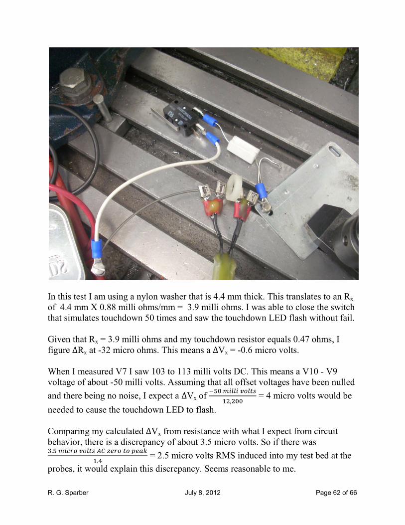
In this test I am using a nylon washer that is 4.4 mm thick. This translates to an Rx
of 4.4 mm X 0.88 milli ohms/mm = 3.9 milli ohms. I was able to close the switch
that simulates touchdown 50 times and saw the touchdown LED flash without fail.
Given that Rx = 3.9 milli ohms and my touchdown resistor equals 0.47 ohms, I
figure ∆Rx at -32 micro ohms. This means a ∆Vx = -0.6 micro volts.
When I measured V7 I saw 103 to 113 milli volts DC. This means a V10 - V9
voltage of about -50 milli volts. Assuming that all offset voltages have been nulled
and there being no noise, I expect a ∆Vx of ����IJJIK�J��
�,��� = 4 micro volts would be
needed to cause the touchdown LED to flash.
Comparing my calculated ∆Vx from resistance with what I expect from circuit
behavior, there is a discrepancy of about 3.5 micro volts. So if there was ,.��Ie��K�J��t#V�����L��W
.� = 2.5 micro volts RMS induced into my test bed at the
probes, it would explain this discrepancy. Seems reasonable to me.
R. G. Sparber July 8, 2012 Page 63 of 66
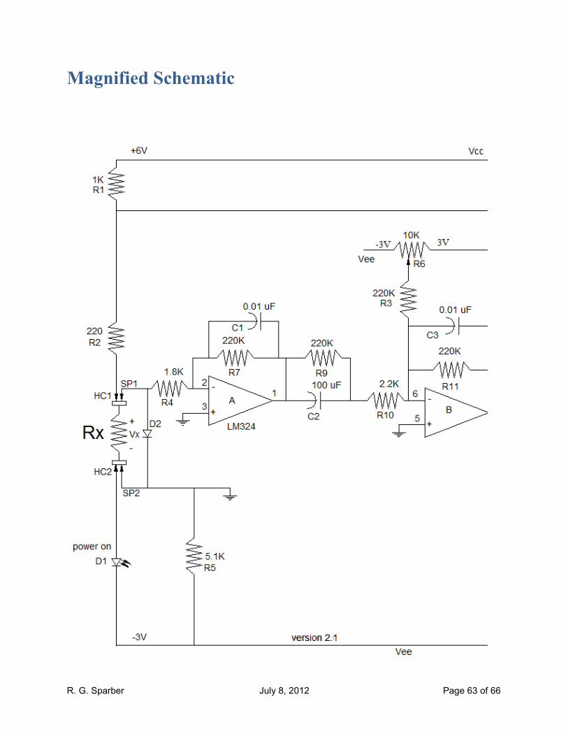
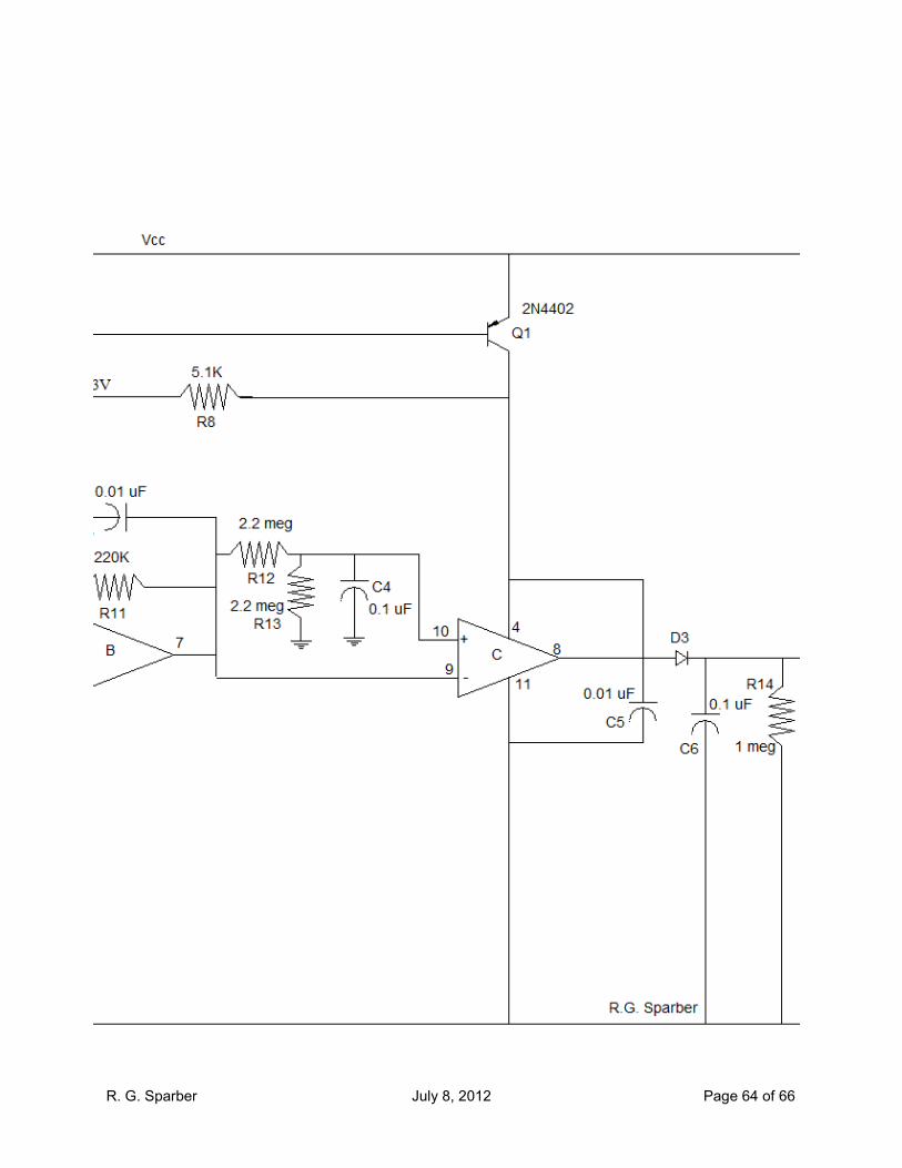
Magnified Schematic
R. G. Sparber July 8, 2012 Page 64 of 66

R. G. Sparber July 8, 2012 Page 65 of 66

R. G. Sparber July 8, 2012 Page 66 of 66
Acknowledgements
Thanks to Dan Benoit for both his encouragement and use of his shop to test out
this design. Thanks to Gregg Kricorissian who critiqued the circuit. Thanks to
Andy Wander for suggesting the coax cable between box and probes. Although I
took it out, it may still go back in at a later date. Thanks to Mark Cason for the
through hole artwork. And finally, thanks to all those on the Yahoo groups
valleymetal, mill_drill and atlas_craftsman for countless comments and
suggestions.
These generous people again demonstrate that “all of us are smarter than any one
of us”.
I welcome your comments and questions.
Rick Sparber
Rick.Sparber.org