selective buckling via states of self-stress in
TRANSCRIPT

Selective buckling via states of self-stress intopological metamaterialsJayson Paulose, Anne S. Meeussen, and Vincenzo Vitelli1
Instituut-Lorentz, Universiteit Leiden, 2300 RA Leiden, The Netherlands
Edited by David A. Weitz, Harvard University, Cambridge, MA, and approved May 11, 2015 (received for review February 13, 2015)
States of self-stress—tensions and compressions of structural ele-ments that result in zero net forces—play an important role in de-termining the load-bearing ability of structures ranging from bridgesto metamaterials with tunable mechanical properties. We exploit aclass of recently introduced states of self-stress analogous to topo-logical quantum states to sculpt localized buckling regions in theinterior of periodic cellular metamaterials. Although the topologicalstates of self-stress arise in the linear response of an idealized me-chanical frame of harmonic springs connected by freely hinged joints,they leave a distinct signature in the nonlinear buckling behavior of acellular material built out of elastic beams with rigid joints. The sa-lient feature of these localized buckling regions is that they areindistinguishable from their surroundings as far as materialparameters or connectivity of their constituent elements are con-cerned. Furthermore, they are robust against a wide range of struc-tural perturbations. We demonstrate the effectiveness of thistopological design through analytical and numerical calculationsas well as buckling experiments performed on two- and three-dimensional metamaterials built out of stacked kagome lattices.
isostatic lattices | topological modes | topological mechanics |tunable failure
Mechanical metamaterials are artificial structures with un-usual properties that originate in the geometry of their
constituents, rather than the specific material they are made of.Such structures can be designed to achieve a specific linear elasticresponse, like auxetic (negative Poisson ratio) (1) or pentamode(zero-shear modulus) (2) elasticity. However, it is often theirnonlinear behavior that is exploited to engineer highly responsivematerials, the properties of which change drastically under appliedstress or confinement (3–7). Coordinated buckling of the buildingblocks of a metamaterial is a classic example of nonlinear behaviorthat can be used to drive the auxetic response (4, 8), modify thephononic properties (5), or generate 3D micro/nanomaterialsfrom 2D templates (9).Buckling-like shape transitions in porous and cellular meta-
materials involve large deformations from the initial shape, typicallystudied through finite element simulations. However, many aspectsof the buckling behavior can be successfully captured in an ap-proximate description of the structure that is easier to analyze (5, 6,10, 11). Here, we connect the mechanics of a cellular metamaterial,a foamlike structure made out of slender flexible elements (12, 13),to that of a frame—a simpler, idealized assembly of rigid beamsconnected by free hinges—with the same beam geometry. We ex-ploit the linear response of a recently introduced class of periodicframes (14), inspired by topologically protected quantum materials,to induce a robust nonlinear buckling response in selected regionsof two- and three-dimensional cellular metamaterials.Frames, also known as trusses, are ubiquitous minimal models
of mechanical structures in civil engineering and materials science.Their static response to an external load is obtained by balancingthe forces exerted on the freely hinged nodes against internalstresses (tensions or compressions) of the beams. However, aunique set of equilibrium stresses may not always be found for anyload (15). First, the structure may have loads that cannot be carriedbecause they excite hinge motions called zero modes that leave all
beams unstressed. Second, the structure may support states of self-stress—combinations of tensions and compressions on the beamsthat result in zero net forces on each hinge. An arbitrary linearcombination of states of self-stress can be added to an internalstress configuration without disrupting static equilibrium, implyingthat degenerate stress solutions exist for any load that can be car-ried. The respective counts Nm and Nss of zero modes and states ofself-stress in a d-dimensional frame with nn nodes and nb beams arerelated to each other by the generalized Maxwell relation (16, 17):
dnn − nb =Nm −Nss. [1]
As Eq. 1 shows, states of self-stress count the excess constraintsimposed by the beams on the dnn degrees of freedom providedby the hinge positions.States of self-stress play a special role in the mechanical re-
sponse of repetitive frames analyzed under periodic boundaryconditions (18). Macroscopic stresses in such systems correspondto boundary loads, which can only be balanced by states of self-stress involving beams that cross the boundaries. If these statesspan the entire system, boundary loads are borne by tensions andcompressions of beams throughout the structure. Conversely, bylocalizing states of self-stress to a small portion of a frame, load-bearing ability is conferred only to that region. Our approachconsists of piling up states of self-stress in a specific region of arepetitive frame so that the beams participating in these states ofself-stress are singled out to be compressed under a uniform loadat the boundary. In a cellular material with the same beam ge-ometry, these beams buckle when the compression exceeds theirbuckling threshold.
Significance
An ongoing challenge in modern materials science is to createartificial structures, termed metamaterials, with an unconven-tional response that can be programmed by suitable design oftheir geometry or topology. We demonstrate a novel meta-material in which small structural variations single out regionsthat buckle selectively under external stresses. Surprisingly, theseregions are at first glance indistinguishable from the rest of thestructure. Our samples are examples of topological meta-materials that are the mechanical analogues of topologicallyprotected electronic systems. As a result, the buckling re-sponse is robust against structural perturbations yet tunablewithout affecting secondary physical properties in the buck-ling region. This feature is desirable for optomechanical orthermomechanical metamaterials in which multiple charac-teristics need to be tuned simultaneously.
Author contributions: J.P., A.S.M., and V.V. designed research; J.P. and A.S.M. performedresearch; J.P., A.S.M., and V.V. contributed new reagents/analytic tools; J.P. and A.S.M.analyzed data; and J.P., A.S.M., and V.V. wrote the paper.
The authors declare no conflict of interest.
This article is a PNAS Direct Submission.1To whom correspondence should be addressed. Email: [email protected].
This article contains supporting information online at www.pnas.org/lookup/suppl/doi:10.1073/pnas.1502939112/-/DCSupplemental.
www.pnas.org/cgi/doi/10.1073/pnas.1502939112 PNAS | June 23, 2015 | vol. 112 | no. 25 | 7639–7644
APP
LIED
PHYS
ICAL
SCIENCE
S
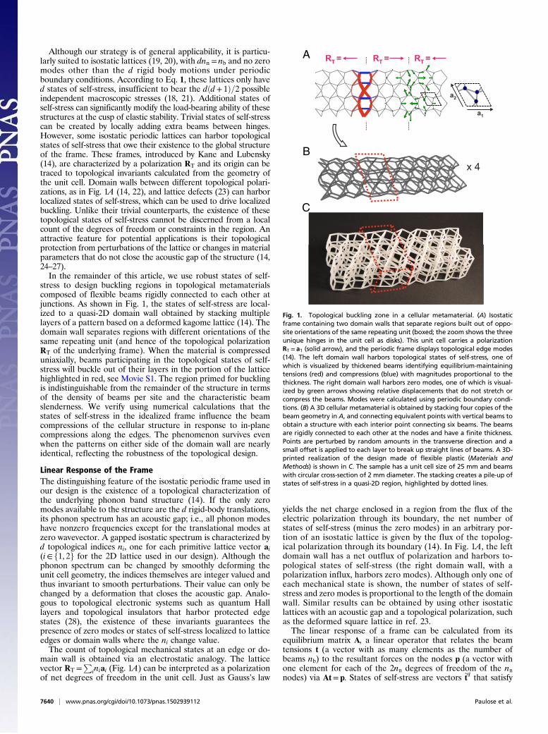
Although our strategy is of general applicability, it is particu-larly suited to isostatic lattices (19, 20), with dnn = nb and no zeromodes other than the d rigid body motions under periodicboundary conditions. According to Eq. 1, these lattices only haved states of self-stress, insufficient to bear the dðd+ 1Þ=2 possibleindependent macroscopic stresses (18, 21). Additional states ofself-stress can significantly modify the load-bearing ability of thesestructures at the cusp of elastic stability. Trivial states of self-stresscan be created by locally adding extra beams between hinges.However, some isostatic periodic lattices can harbor topologicalstates of self-stress that owe their existence to the global structureof the frame. These frames, introduced by Kane and Lubensky(14), are characterized by a polarization RT and its origin can betraced to topological invariants calculated from the geometry ofthe unit cell. Domain walls between different topological polari-zations, as in Fig. 1A (14, 22), and lattice defects (23) can harborlocalized states of self-stress, which can be used to drive localizedbuckling. Unlike their trivial counterparts, the existence of thesetopological states of self-stress cannot be discerned from a localcount of the degrees of freedom or constraints in the region. Anattractive feature for potential applications is their topologicalprotection from perturbations of the lattice or changes in materialparameters that do not close the acoustic gap of the structure (14,24–27).In the remainder of this article, we use robust states of self-
stress to design buckling regions in topological metamaterialscomposed of flexible beams rigidly connected to each other atjunctions. As shown in Fig. 1, the states of self-stress are local-ized to a quasi-2D domain wall obtained by stacking multiplelayers of a pattern based on a deformed kagome lattice (14). Thedomain wall separates regions with different orientations of thesame repeating unit (and hence of the topological polarizationRT of the underlying frame). When the material is compresseduniaxially, beams participating in the topological states of self-stress will buckle out of their layers in the portion of the latticehighlighted in red, see Movie S1. The region primed for bucklingis indistinguishable from the remainder of the structure in termsof the density of beams per site and the characteristic beamslenderness. We verify using numerical calculations that thestates of self-stress in the idealized frame influence the beamcompressions of the cellular structure in response to in-planecompressions along the edges. The phenomenon survives evenwhen the patterns on either side of the domain wall are nearlyidentical, reflecting the robustness of the topological design.
Linear Response of the FrameThe distinguishing feature of the isostatic periodic frame used inour design is the existence of a topological characterization ofthe underlying phonon band structure (14). If the only zeromodes available to the structure are the d rigid-body translations,its phonon spectrum has an acoustic gap; i.e., all phonon modeshave nonzero frequencies except for the translational modes atzero wavevector. A gapped isostatic spectrum is characterized byd topological indices ni, one for each primitive lattice vector ai(i∈ f1, 2g for the 2D lattice used in our design). Although thephonon spectrum can be changed by smoothly deforming theunit cell geometry, the indices themselves are integer valued andthus invariant to smooth perturbations. Their value can only bechanged by a deformation that closes the acoustic gap. Analo-gous to topological electronic systems such as quantum Halllayers and topological insulators that harbor protected edgestates (28), the existence of these invariants guarantees thepresence of zero modes or states of self-stress localized to latticeedges or domain walls where the ni change value.The count of topological mechanical states at an edge or do-
main wall is obtained via an electrostatic analogy. The latticevector RT =
Piniai (Fig. 1A) can be interpreted as a polarization
of net degrees of freedom in the unit cell. Just as Gauss’s law
yields the net charge enclosed in a region from the flux of theelectric polarization through its boundary, the net number ofstates of self-stress (minus the zero modes) in an arbitrary por-tion of an isostatic lattice is given by the flux of the topolog-ical polarization through its boundary (14). In Fig. 1A, the leftdomain wall has a net outflux of polarization and harbors to-pological states of self-stress (the right domain wall, with apolarization influx, harbors zero modes). Although only one ofeach mechanical state is shown, the number of states of self-stress and zero modes is proportional to the length of the domainwall. Similar results can be obtained by using other isostaticlattices with an acoustic gap and a topological polarization, suchas the deformed square lattice in ref. 23.The linear response of a frame can be calculated from its
equilibrium matrix A, a linear operator that relates the beamtensions t (a vector with as many elements as the number ofbeams nb) to the resultant forces on the nodes p (a vector withone element for each of the 2nn degrees of freedom of the nnnodes) via At= p. States of self-stress are vectors ~tq that satisfy
RT = RT = RT =A
x 4B
C
a1
a2
Fig. 1. Topological buckling zone in a cellular metamaterial. (A) Isostaticframe containing two domain walls that separate regions built out of oppo-site orientations of the same repeating unit (boxed; the zoom shows the threeunique hinges in the unit cell as disks). This unit cell carries a polarizationRT = a1 (solid arrow), and the periodic frame displays topological edge modes(14). The left domain wall harbors topological states of self-stress, one ofwhich is visualized by thickened beams identifying equilibrium-maintainingtensions (red) and compressions (blue) with magnitudes proportional to thethickness. The right domain wall harbors zero modes, one of which is visual-ized by green arrows showing relative displacements that do not stretch orcompress the beams. Modes were calculated using periodic boundary condi-tions. (B) A 3D cellular metamaterial is obtained by stacking four copies of thebeam geometry in A, and connecting equivalent points with vertical beams toobtain a structure with each interior point connecting six beams. The beamsare rigidly connected to each other at the nodes and have a finite thickness.Points are perturbed by random amounts in the transverse direction and asmall offset is applied to each layer to break up straight lines of beams. A 3D-printed realization of the design made of flexible plastic (Materials andMethods) is shown in C. The sample has a unit cell size of 25 mm and beamswith circular cross-section of 2 mm diameter. The stacking creates a pile-up ofstates of self-stress in a quasi-2D region, highlighted by dotted lines.
7640 | www.pnas.org/cgi/doi/10.1073/pnas.1502939112 Paulose et al.
A~tq= 0, i.e., they are beam stresses that do not result in net
forces on any nodes (the index q identifies independent nor-malized states of self-stress that span the null space of A). Thesame null vectors are also an orthogonal set of incompatiblestrains of the structure, i.e., beam extensions that cannot be re-alized through any set of point displacements (15).Because we are interested in triggering buckling through
uniform loads that do not pick out any specific region of thelattice, we focus on the response to affine strains, where affinebeam extensions ea are imposed geometrically by some uniformstrain «ij across the sample via
ea α = rαi «ijrαj . [2]
Here, α indexes the beams and rα is the end-to-end vector ofbeam α. To attain equilibrium, the beams take on additionalnonaffine extensions ena. Under periodic boundary conditions,affine strains are balanced by loads across the system boundaryrather than loads on specific nodes, which implies that the re-sultant beam tensions ta = kðea + enaÞ must be constructed solelyout of states of self-stress (18, 29) (we assume for simplicity thatall beams have identical spring constant k). Therefore, ta =P
qxq~tq ≡ ~Tx where ~T= ½~t1,~t2, . . . ,~tNss � and the xq are the weights
of the Nss states of self-stress. These weights are determined byrequiring that the nonaffine strains have zero overlap with the setof incompatible strains (15) (the affine strains are automaticallycompatible with the affine node displacements):
~TTena = ~T
T�1k~Tx− ea
�= 0, [3]
which gives the solution
x= k~TTea [4]
⇒ta = k~T~TTea = k
Xq
ð~tq · eaÞ~tq. [5]
Therefore, the beam tensions under an affine deformation areobtained by projecting the affine strains onto the space of statesof self-stress.Eq. 5 shows that the loading of beams under affine strains is
completely determined by the states of self-stress. In a frameconsisting of a single repeating unit cell, loads are borne uni-formly across the structure. However, if the structure also hasadditional states of self-stress with nonzero entries in ~t
q con-fined to a small region of the frame, it would locally enhancetensions and compressions in response to affine strains, providedthe ~t
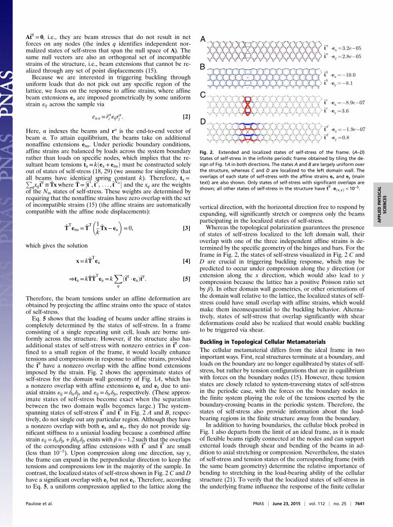
q have a nonzero overlap with the affine bond extensionsimposed by the strain. Fig. 2 shows the approximate states ofself-stress for the domain wall geometry of Fig. 1A, which hasa nonzero overlap with affine extensions ex and ey due to uni-axial strains «ij = δixδjx and «ij = δiyδjy, respectively. (These approx-imate states of self-stress become exact when the separationbetween the two domain walls becomes large.) The system-spanning states of self-stress ~ta and ~t
b in Fig. 2 A and B, respec-tively, do not single out any particular region. Although they havea nonzero overlap with both ex and ey, they do not provide sig-nificant stiffness to a uniaxial loading because a combined affinestrain «ij = δixδjx + βδiyδjy exists with β≈−1.2 such that the overlapsof the corresponding affine extensions with ~t
a and ~tb are small
(less than 10−5). Upon compression along one direction, say y,the frame can expand in the perpendicular direction to keep thetensions and compressions low in the majority of the sample. Incontrast, the localized states of self-stress shown in Fig. 2 C and Dhave a significant overlap with ey but not ex. Therefore, accordingto Eq. 5, a uniform compression applied to the lattice along the
vertical direction, with the horizontal direction free to respond byexpanding, will significantly stretch or compress only the beamsparticipating in the localized states of self-stress.Whereas the topological polarization guarantees the presence
of states of self-stress localized to the left domain wall, theiroverlap with one of the three independent affine strains is de-termined by the specific geometry of the hinges and bars. For theframe in Fig. 2, the states of self-stress visualized in Fig. 2 C andD are crucial in triggering buckling response, which may bepredicted to occur under compression along the y direction (orextension along the x direction, which would also lead to ycompression because the lattice has a positive Poisson ratio setby β). In other domain wall geometries, or other orientations ofthe domain wall relative to the lattice, the localized states of self-stress could have small overlap with affine strains, which wouldmake them inconsequential to the buckling behavior. Alterna-tively, states of self-stress that overlap significantly with sheardeformations could also be realized that would enable bucklingto be triggered via shear.
Buckling in Topological Cellular MetamaterialsThe cellular metamaterial differs from the ideal frame in twoimportant ways. First, real structures terminate at a boundary, andloads on the boundary are no longer equilibrated by states of self-stress, but rather by tension configurations that are in equilibriumwith forces on the boundary nodes (15). However, these tensionstates are closely related to system-traversing states of self-stressin the periodic case, with the forces on the boundary nodes inthe finite system playing the role of the tensions exerted by theboundary-crossing beams in the periodic system. Therefore, thestates of self-stress also provide information about the load-bearing regions in the finite structure away from the boundary.In addition to having boundaries, the cellular block probed in
Fig. 1 also departs from the limit of an ideal frame, as it is madeof flexible beams rigidly connected at the nodes and can supportexternal loads through shear and bending of the beams in ad-dition to axial stretching or compression. Nevertheless, the statesof self-stress and tension states of the corresponding frame (withthe same beam geometry) determine the relative importance ofbending to stretching in the load-bearing ability of the cellularstructure (21). To verify that the localized states of self-stress inthe underlying frame influence the response of the finite cellular
A
B
C
D
Fig. 2. Extended and localized states of self-stress of the frame. (A–D)States of self-stress in the infinite periodic frame obtained by tiling the de-sign of Fig. 1A in both directions. The states A and B are largely uniform overthe structure, whereas C and D are localized to the left domain wall. Theoverlaps of each state of self-stress with the affine strains ex and ey (maintext) are also shown. Only states of self-stress with significant overlaps areshown; all other states of self-stress in the structure have ~t
q·efx, yg < 10−5.
Paulose et al. PNAS | June 23, 2015 | vol. 112 | no. 25 | 7641
APP
LIED
PHYS
ICAL
SCIENCE
S

structure, we numerically calculate the in-plane response of eachlayer treated as an independent 2D cellular structure withloading confined to the 2D plane. Each beam provides not justaxial tension/compression resistance but also resistance to shearand bending. A beam of length L, cross-sectional area A, andarea moment of inertia I resists (i) axial extensions e with atension t= ðEA=LÞe, (ii) transverse deformations es with a re-storing shear force s= 12ðEI=L3Þes, and (iii) angular deflectionsof the end nodes θ with restoring moment m= ðEI=LÞθ (Fig. 3).Because A∼w2 and I ∼w4 for a beam of width w, the relativecontribution of the bending, shear and torsional components tothe total stiffness is set by the aspect ratio w=L of each beam; theframe limit with no bending or shear stiffness is recovered whenw=L→ 0. The physical sample has beams with aspect ratios in therange 0.1Kw=LK 0.2, indicating a small but appreciable con-tribution of shear and torsion to the response.The 2D linear response of such a structure is calculated by
augmenting the equilibrium matrix A to include an additionaldegree of freedom (a rigid rotation angle) at each node, and twoadditional restoring forces (shear and torsion) for each beam,see Materials and Methods. The resulting equilibrium matrix is ofsize 3nn × 3nb, which implies that cellular solids based on isostaticframes with nb ≈ dnn are severely overconstrained for d= 2, 3,and structurally stable even with free boundaries. In particular,they can support any loads exerted on the boundary nodes as longas the net forces and torques about the center of mass are zero.Once the equilibrium matrix is constructed, its singular valuedecomposition can be used to completely determine all stressesand torques experienced by the beams in response to forces
specified on the boundary nodes (15). Fig. 3 shows the linearresponse of each plane of the cellular pattern corresponding tothe domain wall geometry of Fig. 2 under uniform compressiveforce applied to the nodes on the top and bottom edges. Thebeams participating in the states of self-stress at the left domainwall are singled out by their high compression; in contrast, therest of the structure primarily supports the boundary loadthrough shear rather than compression or bending. Remarkably,the unique compression-dominated response of the left domainwall (originating from the topological invariant in the idealizedisostatic frame with freely hinged joints) survives in cellularstructures away from the isostatic condition.We expect a similar localized compression-dominated response
in each layer of the stacked structure (Fig. 1 B and C). The en-hanced compressions along the left domain wall trigger bucklingwhen the compression exceeds the Euler beam buckling threshold,ti <−cEI=L2
i , where c is a positive numerical factor determined bythe clamping conditions as well as cooperative buckling effects.Buckling is signified by a loss of ability to bear axial loads, as thebeam releases its compression by bending out of plane. Uponcompressing the 3D sample between two plates as shown in Fig.4A, we see a significant out-of-plane deflection for beams alongthe left domain wall (Fig. 4 B and C), consistent with buckling ofthe maximally stressed beams in Fig. 3A. The deflection in dif-ferent layers is coordinated by the vertical beams connectingequivalent points, so that beams within the same column buckleeither upwards (column 1) or downward (column 2) to produce adistinctive visual signature when viewed along the compressionaxis. Beams connecting different planes in the stacked patterncreate additional states of self-stress that traverse the samplevertically, but these do not single out any region of the material,and do not couple to the specific in-plane loading of Fig. 4A.We emphasize that having as many states of self-stress as there
are unit cells along the domain wall is crucial for the buckling tooccur throughout the domain wall. When a beam buckles, itscontribution to the constraints of distances between nodes es-sentially disappears, reducing the number of load-bearing con-figurations by one. If there were only a single localized state ofself-stress in the system, the buckling of a single beam wouldeliminate this state, and the compressions on the other beamswould be relaxed, preventing further buckling events. However,the presence of multiple states of self-stress, guaranteed in thiscase by the topological origin of the states, allows many bucklingevents along the domain wall. In the SI Text, we use an adaptivesimulation that sequentially removes highly compressed beamsto show that each repeating unit along the y direction experi-ences a unique buckling event even when the loss of constraintsdue to other buckling events is taken into account (Fig. S1).
Robustness of the Buckling RegionFinally, we show that the robustness of the topological states ofself-stress predicted within linear elastic theory carries over tothe buckling response in the nonlinear regime. There is a widerange of distortions of the deformed kagome unit cell which donot close the acoustic gap, leaving the topological invariants niand hence the polarization RT unchanged (14). These distortionsmay bring the unit cell arbitrarily close to the regular kagomelattice with equilateral triangles of beams (for which the gap isclosed and the polarization is undefined). The unit cell of the2D lattice shown in Fig. 5A is minimally distorted away fromthe regular kagome lattice, but this barely noticeable distor-tion (Fig. 5A, Inset) is sufficient to induce the same topologicalpolarization RT in the underlying frame as before. As a result,the domain wall on the left (characterized by a net outflux ofpolarization) localizes states of self-stress (shown in Fig. S2),even though the unit cells are nearly identical on either side.For ease of visualization, we tested this design in a 2D pro-
totype cellular metamaterial, obtained by laser-cutting voids in a
e
es
es
e
A
B
C
Fig. 3. Stretching, shear, and bending contributions to the linear in-planeresponse of the cellular metamaterial. Response of a planar cellular struc-ture, related to the lattice in Fig. 2 but with free edges, subject to a verticalcompressive force F (solid arrows) at each point highlighted along the topand bottom edges. The structure is modeled as a network of flexible beamsconnected by rigid joints at the nodes, and with each beam providing tor-sional stiffness in addition to axial stiffness. The beams are colored accordingto (A) axial compression; (B) shear load; and (C) bending moment.
7642 | www.pnas.org/cgi/doi/10.1073/pnas.1502939112 Paulose et al.

1.5-cm-thick slab of polyethylene foam (Materials and Methods),leaving behind beams 1–2 mm wide and 10–12 mm long (Fig.5A). The aspect ratio of the beams is comparable to that of the3D sample. Because the slab thickness is much larger than thebeam width, deformations are essentially planar and uniformthrough the sample thickness, and can be captured by an overheadimage of the selectively illuminated top surface. The sample wasconfined between rigid acrylic plates in free contact with the top
and bottom edges, and subjected to a uniaxial in-plane compres-sion along the vertical direction by reducing the distance betweenthe plates. Using image analysis (Materials and Methods) wecomputed the beams’ tortuosity, defined as the ratio of the con-tour length of each beam to its end-to-end distance. Buckledbeams have a tortuosity significantly above 1. Under a verticalcompression of 4%, only beams along the left domain wall show atortuosity above 1.05, consistent with a localized buckling response(Fig. 5B). However, under higher strains, the response of thelattice qualitatively changes. When beams have buckled along theentire domain wall, its response to further loading is no longercompression dominated (Fig. S1). Future buckling events, whichare triggered by coupling between torsional and compressionalforces on beams due to the stiff hinges, no longer single out theleft domain wall and happen uniformly throughout the sample(Fig. 5C and Movie S2).We have demonstrated that piling up localized states of self-
stress in a small portion of an otherwise bending-dominatedcellular metamaterial can induce a local propensity for buckling.Whereas this principle is of general applicability, our buckling re-gions exploit topological states of self-stress (14), which providetwo advantages. First, they are indistinguishable from the rest ofthe structure in terms of node connectivity and material parame-ters, allowing mechanical response to be locally modified withoutchanging the thermal, electromagnetic, or optical properties. Thisfeature could be useful for optomechanical (30) or thermo-mechanical (31) metamaterial design. Second, the buckling regionsare robust against structural perturbations, as long as the acousticbulk gap of the underlying frame is maintained. This gap is aproperty of the unit cell geometry. Large deformations that closethe gap could be induced through external actuation (32) or con-finement, potentially allowing a tunable response from localized toextended buckling in the same sample, reminiscent of electricallytunable band gaps in topological insulators (33).
Materials and MethodsDeformed Kagome Lattice Unit Cell. The deformed kagome lattices are ob-tained by decorating a regular hexagonal lattice, built from the primitivelattice vectors fa1 = ax, a2 =−ða=2Þx + ð ffiffiffi
3p
a=2Þyg, where a is the lattice con-stant, with a three-point unit cell that results in triangles with equal sizes. Theunit cells are described by a parameterization introduced in ref. 14, which usesthree numbers ðx1, x2, x3Þ to quantify the distortion of lines of bonds away froma regular kagome lattice (xi =0). The unit cell in Fig. 1A, which forms the basisfor the 3D cellular structure, is reproduced by ðx1, x2, x3Þ= ð−0.1, 0.06, 0.06Þ
A B
C
1
21
2Fig. 4. Buckling in the 3D topological cellular metamaterial. (A) Top view of the 3D sample (constructed as outlined in Fig. 1) showing the compressionapplied by confining the sample between transparent plates in contact with the front and back surfaces. The buckling zone is highlighted in red as in Fig. 1.Two vertical columns within this zone are labeled in yellow. Magenta arrows show the compression direction. (B and C) View along the compression axis atcompressions of 0 and 20%, respectively. The beams in the region with states of self-stress have buckled in the vertical direction, whereas other beams havelargely deformed within their stacking planes. (Scale bar, 25 mm.)
RT = RT = RT =A
B
C
Fig. 5. Buckling is robust under polarization-preserving changes of the unitcell. (A) A 2D foam cellular prototype, whose unit cell maintains the topo-logical polarization RT even though its distortion away from the regularkagome lattice is small (a zoom of the constituent triangles is shown withinthe yellow circle). The domain wall geometry is identical to that of the 3Dsample, with the left domain wall localizing states of self-stress. (Scale bar,2 cm.) (B) Response of the structure under a vertical compression of 4% withfree left and right edges. The beams are colored by the tortuosity, the ratioof the initial length of the beam to the end-to-end distance of the deformedsegment (color bar). (C) Response of the structure under 7% compression,with beams colored by tortuosity using the same color scale as in B.
Paulose et al. PNAS | June 23, 2015 | vol. 112 | no. 25 | 7643
APP
LIED
PHYS
ICAL
SCIENCE
S
for which the topological polarization is RT =−a1 (14). The unit cell for thedesign in Fig. 5A parameterized by ð−0.025, 0.025, 0.025Þ has the same po-larization. In all cases we describe the unit cell and polarization in the outerregion; the inner region between the domain walls rotates this unit cell byπ, which flips the polarization direction.
Construction of the Equilibrium/Compatibility Matrix. Analysis of the linearresponse of a frame or a cellular material begins with the construction of theequilibrium matrix A. Because it is more natural to relate node displacementsto beam length changes, we describe how to build the compatibility matrixC=AT, relating point displacements u to extensions e via Cu= e. We con-struct the compatibility matrix from the contributions of individual beams.Consider a single beam aligned to the x axis connecting hinge 1 at ð0, 0Þ tohinge 2 at ðL, 0Þ. There are six degrees of freedom potentially constrained bythe beam: the positions ðxi , yiÞ at each node i and the torsion angle θi. WithinEuler–Bernoulli beam theory, these values are sufficient to determine theshape of the beam along its length as well as the forces and torques at eachend needed to maintain equilibrium (34). Three independent combinationsof forces and torques can be identified and which are proportional togeneralized strains experienced by the beam: pure tension t ∝ x2 − x1, pureshear s∝ y2 − y1 − Lðθ1 + θ2Þ=2, and pure bending torque m∝ θ2 − θ1, as il-lustrated schematically in Fig. 3. In matrix form, this gives
e=
0@−1 0 0 1 0 0
0 −1 −L=2 0 1 −L=20 0 −1 0 0 1
1A ·
0BBBBBB@
x1y1θ1x2y2θ2
1CCCCCCA≡Cu. [6]
The forces and torque (generalized stresses) are obtained from the gener-alized strains e through the stiffness matrix K, which depends on the Young’smodulus E, the cross-sectional area A, the area moment of inertia I, and thebeam length L:
σ ≡
0@ t
sm
1A=
0@EA=L 0 0
0 12EI�L3 0
0 0 EI=L
1A· e≡Ke. [7]
The compatibility matrix for a beam with arbitrary orientation is obtained byprojecting the displacement vectors at the end of each beamonto the axial and
transverse directions using the appropriate rotation matrix, which depends onthe angle made by the beam with the x axis. Each beam in an assembly pro-vides three rows to the compatibility matrix, with additional columns set tozero for the degrees of freedom unassociated with that beam. In the simplerframe limit, each beam only resists axial extensions, and contributes one row(the first row of the C matrix in Eq. 6) to the compatibility matrix.
Once the equilibrium matrix is constructed, the approximate states of self-stress of the periodic frame (Fig. 2) as well as the linear response of thecellular material under loads (Fig. 3) are obtained from its singular valuedecomposition following the methods of ref. 15. More details of the com-putation are provided in the SI Text.
Construction and Characterization of 2D and 3D Prototypes. The 3D structureswere printed by Materialise N.V. through laser sintering of their proprietarythermoplastic polyurethane TPU 92A-1 (tensile strength 27 MPa, density 1.2g/cm3, Young’s modulus 27 MPa).
The 2D structures were cut using a VersaLaser 3.5 laser cutter (Laser & SignTechnology) from 1.5 cm thick sheets of closed-cell cross-linked polyethylenefoam EKI-1306 (EKI B.V.; tensile strength 176 kPa, density 0.03 g/cm3,Young’s modulus 1.7 MPa). A characteristic load-compression curve of a 2Dsample is shown in Fig. S3.
Image Analysis of 2D Experiment. Images of the 2D cellular prototype (Fig. 5)were obtained using a Nikon CoolPix P340 camera and stored as 3,000 ×4,000 px 24-bit JPEG images. To quantitatively identify the buckled beamsin the 2D prototype under confinement, we extracted the tortuosity τ of eachbeam, defined as the ratio of the length of the beam to the distance betweenits endpoints. Tortuosity was estimated from the sample images through aseries of morphological operations, as detailed in SI Text and Fig. S4. Straightbeams have τ= 1, whereas beams that buckle under axial compression haveτ> 1. Unlike other measures of curvature, tortuosity distinguishes buckledbeams from sheared beams (schematic, Fig. 3B), which have τJ 1.
ACKNOWLEDGMENTS. We thank Denis Bartolo, Bryan Chen, Martin vanHecke, Charlie Kane, and Tom Lubensky for useful discussions, and JeroenMesman at the Leiden University Fine Mechanics Department for designingand building the compression stage. This work was funded by the Foundationfor Fundamental Research onMatter and by the Delta Institute for TheoreticalPhysics, a program of The Netherlands Organization for Scientific Research,which is funded by the Dutch Ministry of Education, Culture, and Science.
1. Lakes R (1987) Foam structures with a negative Poisson’s ratio. Science 235(4792):1038–1040.
2. Kadic M, Buckmann T, Stenger N, Thiel M, Wegener M (2012) On the practicability ofpentamode mechanical metamaterials. Appl Phys Lett 100:191901.
3. Shim J, et al. (2013) Harnessing instabilities for design of soft reconfigurable auxetic/chiral materials. Soft Matter 9:8198–8202.
4. Babaee S, et al. (2013) 3D soft metamaterials with negative Poisson’s ratio. Adv Mater25(36):5044–5049.
5. Shan S, et al. (2014) Harnessing multiple folding mechanisms in soft periodic struc-tures for tunable control of elastic waves. Adv Funct Mater 24(31):4935–4942.
6. Florijn B, Coulais C, van Hecke M (2014) Programmable mechanical metamaterials.Phys Rev Lett 113(17):175503.
7. Driscoll MM, Chen BG-g, Beuman TH, Ulrich S, Nagel SR, Vitelli V (2015) Tunablefailure in marginally rigid matter. arXiv 1501.04227v1.
8. Bertoldi K, Reis PM, Willshaw S, Mullin T (2010) Negative Poisson’s ratio behaviorinduced by an elastic instability. Adv Mater 22(3):361–366.
9. Xu S, et al. (2015) Materials science. Assembly of micro/nanomaterials into complex,three-dimensional architectures by compressive buckling. Science 347(6218):154–159.
10. Matsumoto EA, Kamien RD (2009) Elastic-instability triggered pattern formation. PhysRev E Stat Nonlin Soft Matter Phys 80(2 Pt 1):021604.
11. Kang SH, et al. (2014) Complex ordered patterns in mechanical instability inducedgeometrically frustrated triangular cellular structures. Phys Rev Lett 112(9):098701.
12. Gibson L (1989) Modelling the mechanical behavior of cellular materials. Mater SciEng A 110:1–36.
13. Jang D, Meza LR, Greer F, Greer JR (2013) Fabrication and deformation of three-di-mensional hollow ceramic nanostructures. Nat Mater 12(10):893–898.
14. Kane CL, Lubensky TC (2014) Topological boundary modes in isostatic lattices. NatPhys 10:39–45.
15. Pellegrino S (1993) Structural computations with the singular value decomposition ofthe equilibrium matrix. Int J Solids Struct 30:3025–3035.
16. Maxwell JC (1864) On the calculation of the equilibrium and stiffness of frames. PhilosMag 27:294–299.
17. Calladine C (1978) Buckminster Fuller’s tensegrity structures and Clerk Maxwell’s rulesfor the construction of stiff frames. Int J Solids Struct 14:161–172.
18. Guest S, Hutchinson J (2003) On the determinacy of repetitive structures. J Mech PhysSolids 51:383–391.
19. Liu AJ, Nagel SR (2010) The jamming transition and the marginally jammed solid.Annu Rev Condens Matter Phys 1:347–369.
20. Lubensky TC, Kane CL, Mao X, Souslov A, Sun, K (2015) Phonons and elasticity incritically coordinated lattices. arXiv 1503.01324.
21. Deshpande VS, Ashby MF, Fleck NA (2001) Foam topology: Bending versus stretchingdominated architectures. Acta Mater 49:1035–1040.
22. Chen BG, Upadhyaya N, Vitelli V (2014) Nonlinear conduction via solitons in a topo-logical mechanical insulator. Proc Natl Acad Sci USA 111(36):13004–13009.
23. Paulose J, Chen BG-g, Vitelli V (2015) Topological modes bound to dislocations inmechanical metamaterials. Nat Phys 11:153–156.
24. Prodan E, Prodan C (2009) Topological phonon modes and their role in dynamic in-stability of microtubules. Phys Rev Lett 103(24):248101.
25. Vitelli V (2012) Topological soft matter: Kagome lattices with a twist. Proc Natl AcadSci USA 109(31):12266–12267.
26. Sun K, Souslov A, Mao X, Lubensky TC (2012) Surface phonons, elastic response, andconformal invariance in twisted kagome lattices. Proc Natl Acad Sci USA 109(31):12369–12374.
27. Vitelli V, Upadhyaya N, Chen BG-g (2014) Topological mechanisms as classical spinorfields. arXiv 1407.2890.
28. Franz M, Molenkamp L (2013) Topological Insulators. Contemporary Concepts ofCondensed Matter Science (Elsevier, Oxford).
29. Stenull O, Lubensky TC (2014) Penrose tilings as jammed solids. Phys Rev Lett 113(15):158301.
30. Eichenfield M, Chan J, Camacho RM, Vahala KJ, Painter O (2009) Optomechanicalcrystals. Nature 462(7269):78–82.
31. Guda Vishnu K, Strachan A (2013) Shape memory metamaterials with tunablethermo-mechanical response via hetero-epitaxial integration: A molecular dynamicsstudy. J Appl Phys 113:103503.
32. Leung A, Guest S (2007) Single member actuation of kagome lattice structures.J Mech Mat Struct 2:303–317.
33. Drummond ND, Zlyomi V, Fal’ko VI (2012) Electrically tunable band gap in silicene.Phys Rev B 85:075423.
34. Logan DL (2007) A First Course in the Finite Element Method (Thomson, Ontario).
7644 | www.pnas.org/cgi/doi/10.1073/pnas.1502939112 Paulose et al.
Supporting InformationPaulose et al. 10.1073/pnas.1502939112SI TextSVD Analysis of Equilibrium Matrix. The linear response of theframe as well as the cellular metamaterial are obtained using thesingular value decomposition (SVD) of the equilibrium matrix, asdetailed in ref. 15 and summarized below. The SVD analysissimultaneously handles the spaces of node forces as well as beamstresses, and properly takes into account states of self-stress in thestructure.The SVD of the equilibrium matrix A with nr rows and nc
columns expresses it as the product of three matrices:
A=UVWT, [S1]
where U= ½u1, . . . , unr � is a square matrix composed of nr inde-pendent column vectors ui, W= ½w1, . . . ,wnc � is a square matrixof nc independent column vectors wi, and V is a matrix with rnonnegative values vii on the leading diagonal and all other val-ues zero, r being the rank of A.The first r columns ui of U provide the finite-energy dis-
placement modes of the structure, whereas the remaining nr − rcolumn vectors are the zero modes. Similarly, the first r andremaining nc − r column vectors of W provide the finite-energybond tension configurations and the states of self-stress,respectively.For the frame in Fig. 2 under periodic boundary conditions, the
count of topological states of self-stress predicts eight localizedstates of self-stress if the left domain wall were isolated, in ad-dition to the two extended states of self-stress expected underperiodic boundary conditions. However, because the separationbetween the left and right domain walls is finite, the SVD pro-duces only two actual states of self-stress, and six approximatestates of self-stress with large vii. The corresponding tensionconfigurations ~tq ≡wnc−q are the last eight column vectors of W.For of these (wnc−7, wnc−6, wnc−1, and wnc) have a significantoverlap with «xx or «yy. These are displayed in Fig. 2 A–D,respectively.The response of the cellular network in Fig. 3 is calculated for
the finite block with free edges. Unlike the frame, this is highlyoverconstrained and has many generalized states of self-stress(now corresponding to mixtures of tensions, shears, and torquesthat maintain equilibrium). An external load l, corresponding to aforce specification on each point, is supportable by the structureprovided its overlap with the space of zero-energy motions iszero; i.e.,
½ur+ 1, . . . , unr �Tl= 0. [S2]
Because the cellular block only has three zero motions corre-sponding to the two translations and one rotation, any set offorces with no net force or torque on the structure, such as theforce configuration shown in Fig. 3A, satisfies this condition.The generalized stresses σ (three per beam) are then given by
σ =Xr
i=1
ui · lvii
wi +Wnc−rx, [S3]
where the second term is an arbitrary combination of the states ofself-stress given by the last nc − r columns ofW. The weights x aredetermined by requiring zero overlap of the generalized strainswith the incompatible strains (states of self-stress), which leadsto the equation
WTnc−rK
−1Wnc−rx=−WTnc−rK
−1Xr
i=1
ui · lvii
wi, [S4]
which can be solved for x to get the complete generalized stresses(three per beam, plotted separately in Fig. 3 A–C).
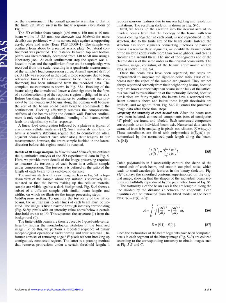
Sequential Removal of Beams. Fig. 3 showed that the axial com-pressions in the cellular material under uniaxial loading wereconcentrated along the left domain wall, matching the expecta-tion from the analysis of the frame with similar beam geometry.However, every time a beam buckles, its axial load-bearing abilityis lost. This fundamentally changes the load-bearing states of theunderlying frame, and there is no guarantee that the beams withthe highest compression continue to be along the left domain wall.However, the number of topological states of self-stress localizedto the left domain wall in the underlying periodic frame growslinearly with the length of the domain wall (14), suggesting thatthe load-bearing ability of the left domain wall may not vanishcompletely with just a single buckling event. Here, we numericallyshow using a sequential analysis of the finite cellular frame thatthe left domain wall can support as many buckling events as thereare repeating units along the y direction.To recap, Fig. 3A shows the compressions in a finite cellular
block, obtained by tiling the same pattern 3 times along the ydirection, under forces applied to undercoordinated points at thetop and bottom edge. Because the threshold for buckling undercompression scales as 1=L2
i for beam i of length Li, we expectthat the beam with the largest value of −tiL2
i will buckle first asthe compressive force F is increased. We examine the influenceof the buckling event on the compression response by removingthis beam from the cellular structure and recalculating the axialtensions t without changing the forces on the boundary points.This process can be repeated, sequentially removing the beamwith the largest value of −tiL2
i after the linear response of thecellular structure has been recalculated. The result is show inFig. S1, in which beams are colored by −tiL2
i =F, i.e., the beamwith the highest intensity in each iteration is removed in the next.For the first three iterations of the sequential process, the beamchosen for removal lies along the left domain wall (Fig. S1 A–C),showing that the multiplicity of load-bearing states localized tothe left domain wall is sufficient for at least one buckling event tooccur for each repeating unit of the domain wall.Furthermore, after each repeating unit along the y direction
has experienced buckling, the beams in the rest of the latticeexperience much lower compressions relative to the initialcompressions along the left domain wall (Fig. S1D), signifyingthat the lattice remains entirely bending/shear dominated awayfrom the domain wall.By performing simulations on different system sizes, we con-
firmed that upon increasing the sample size along the y direction,the number of buckling events localized to the left domain wallincreases proportionally.
Load-Compression Curve of a 2D Sample. A rudimentary measure-ment (Fig. S3) of the load-compression curve of a 2D cellularprototype has been performed to assess the effect of the lo-calized buckling events on the mechanical response. The pro-totype, shown in Fig. S3B, uses a unit cell characterized byðx1, x2, x3Þ= ð−0.085, 0.085, 0.085Þ in the parameterization of ref.14. This is geometrically similar to the unit cell used for the 3Dsample in the main text and has the same polarization. However,we use more unit cells in the 2D sample to reduce edge effects
Paulose et al. www.pnas.org/cgi/content/short/1502939112 1 of 6
on the measurement. The overall geometry is similar to that ofthe finite 2D lattice used in the linear response calculations ofFig. 3.The 2D cellular foam sample (460 mm × 150 mm × 15 mm;
beam widths 1.5–2.5 mm; see Materials and Methods for moredetails) was positioned with its narrow edge against a supportingacrylic plate and scale (Kern PCB 10000–1). The sample wasconfined from above by a second acrylic plate. No lateral con-finement was provided. The distance between top and bottomplates was incrementally decreased from 140 to 90 mm using alaboratory jack. At each confinement step the system was al-lowed to relax and the equilibrium force on the sample edge wasrecorded from the scale, resulting in a quasistatic measurementof the sample’s load-compression curve. A small upward drift ofca. 0.5 kN was recorded in the scale’s force response due to longrelaxation times. This drift (assumed to be linear in the con-finement) has been subtracted from the recorded data. Thecomplete measurement is shown in Fig. S3A. Buckling of thebeams along the domain wall leaves a clear signature in the formof a sudden softening of the response (region highlighted in red).Before buckling, the main resistance to confinement was pro-vided by the compressed beams along the domain wall becausethe rest of the beams could easily bend to accommodate theconfinement. Buckling effectively removes the compressionalstiffness of the beams along the domain wall. Further confine-ment is only resisted by additional bending of all beams, whichleads to a significantly softer response.A linear load compression followed by a plateau is typical of
elastomeric cellular materials (12). Such materials also tend tohave a secondary stiffening regime due to densification whenadjacent beams contact each other along their lengths. In ourmeasurement, however, the entire sample buckled in the lateraldirection before this regime could be reached.
Details of 2D Image Analysis. InMaterials and Methods, we outlinedthe quantitative analysis of the 2D experimental data in Fig. 5.Here, we provide more details of the image processing requiredto measure the tortuosity of each beam in a cellular sampleunder compression. The tortuosity is defined as the ratio of thelength of each beam to its end-to-end distance.The analysis starts with a raw image such as in Fig. 5A, a top–
down view of the sample whose top surface is selectively illu-minated so that the beams making up the cellular materialsample are visible against a dark background. Fig. S4A shows asubset of a different sample with similar beam lengths andwidths, on which we illustrate the image processing steps.Isolating beam sections. To quantify the tortuosity of the latticebeams, the neutral axis (center line) of each beam must be iso-lated. The image is first binarized through intensity thresholding(Fig. S4B): pixels with an intensity value above/below a certainthreshold are set to 1/0. This separates the structure (1) from thebackground (0).The finite-width beams are then reduced to 1-pixel-wide center
lines by finding the morphological skeleton of the binarizedimage. To do this, we perform a repeated sequence of binarymorphological operations: skeletonizing and spur removal. Theformer consists of removing edge “1” pixels without breaking upcontiguously connected regions. The latter is a pruning methodthat removes protrusions under a certain threshold length; it
reduces spurious features due to uneven lighting and resolutionlimitations. The resulting skeleton is shown in Fig. S4C.Next, we break up the skeleton into the neutral axes of in-
dividual beams. Note that the topology of the frame, with fourbeams coming together at each joint, is not reproduced in theskeleton, due to the finite size of the beam joints. Instead, theskeleton has short segments connecting junctions of pairs ofbeams. To remove these segments, we identify the branch pointsof the skeleton (pixels with more than two neighbors) and clear acircular area around them. The size of the segments and of thecleared disk is of the same order as the original beam width. Theresulting image, consisting of the beams’ approximate neutralaxes, is shown in Fig. S4.Once the beam axes have been separated, two steps are
implemented to improve the signal-to-noise ratio. First of all,beams near the edges of the sample are ignored. They are notalways separated correctly from their neighboring beams, becausethey have lower connectivity than beams in the bulk of the lattice;this can lead to overestimation of the tortuosity. Second, becauseour lattices are fairly regular, the beams have a restricted size.Beam elements above and below these length thresholds areartifacts, and we ignore them. Fig. S4E illustrates the processedimage data after these final steps.Computing the tortuosity of each neutral axis. After the beam axeshave been isolated, connected components (sets of contiguous“1” pixels) are found and labeled. Each connected componentcorresponds to an individual beam axis. Numerical data can beextracted from it by analyzing its pixels’ coordinates, rp!= ðxp, ypÞ.These coordinates are fitted with polynomials ðxðlÞ, yðlÞÞ pa-rameterized by the normalized path length along the beam,l∈ ½0,1�:
�xðlÞyðlÞ
�=
X3i=0
�aibi
�li. [S5]
Cubic polynomials in l successfully capture the shape of theneutral axis of each beam, and smooth out pixel noise, whichleads to small-wavelength features in the binary skeleton. Fig.S4F displays the smoothed contours superimposed on the orig-inal image, showing that the shapes of the individual beam sec-tions are faithfully reproduced by the parametric form of Eq. S5.The tortuosity τ of the beam axes is the arc length A along the
line divided by the distance D between the endpoints. Bothquantities can be extracted from the fitted model of the beamaxes,~rðlÞ= ðxðlÞ, yðlÞÞ:
A=Z1
0
ffiffiffiffiffiffiffiffiffiffiffiffiffiffiffiffiffiffiffiffiffiffiffiffiffiffiffiffiffiffiffiffi�dxdl
�2
+�dydl
�2s
dl, [S6]
D=��~rð1Þ−~rð0Þ��. [S7]
Once the tortuosities of the beam segments have been computed,pixels in each segment of the binary image (Fig. S4B) are coloredaccording to the corresponding tortuosity to obtain images suchas Fig. 5 B and C.
Paulose et al. www.pnas.org/cgi/content/short/1502939112 2 of 6
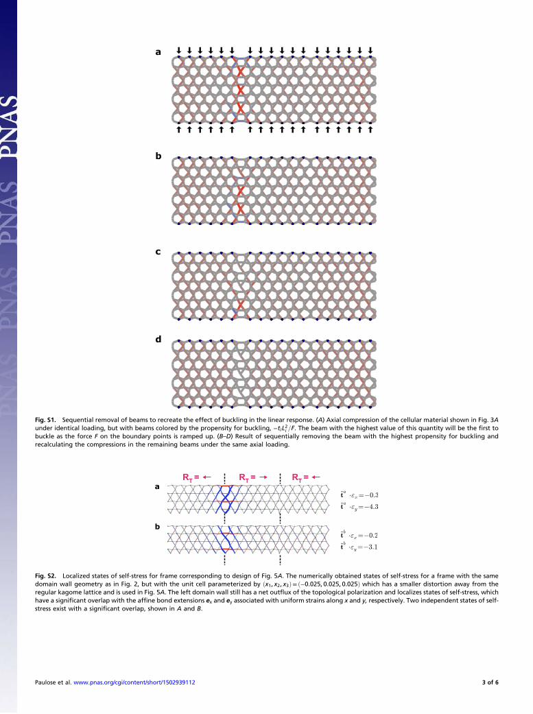
Fig. S1. Sequential removal of beams to recreate the effect of buckling in the linear response. (A) Axial compression of the cellular material shown in Fig. 3Aunder identical loading, but with beams colored by the propensity for buckling, −tiL2i =F. The beam with the highest value of this quantity will be the first tobuckle as the force F on the boundary points is ramped up. (B–D) Result of sequentially removing the beam with the highest propensity for buckling andrecalculating the compressions in the remaining beams under the same axial loading.
RT = RT = RT =
Fig. S2. Localized states of self-stress for frame corresponding to design of Fig. 5A. The numerically obtained states of self-stress for a frame with the samedomain wall geometry as in Fig. 2, but with the unit cell parameterized by ðx1, x2, x3Þ= ð−0.025, 0.025, 0.025Þ which has a smaller distortion away from theregular kagome lattice and is used in Fig. 5A. The left domain wall still has a net outflux of the topological polarization and localizes states of self-stress, whichhave a significant overlap with the affine bond extensions ex and ey associated with uniform strains along x and y, respectively. Two independent states of self-stress exist with a significant overlap, shown in A and B.
Paulose et al. www.pnas.org/cgi/content/short/1502939112 3 of 6

Fig. S3. Measurement of the total confining force as a function of imposed strain for a 2D cellular prototype sample (Fig. 5). (A) The measured data (blackcircles) and an estimate of the measurement error (dark gray contour) are shown. The red region indicates the strain regime in which the beams within thetopologically rigid domain wall buckle. In the light gray region, the sample response is dominated by out-of-plane buckling of the entire sample rather than byin-plane deformations of the cellular structure. The error was estimated at 0.2 kN based on uncertainties in the compression and force due to the rudimentarymeasurement apparatus; (B) the 2D cellular prototype for which the load-compression curve was measured. Its unit cell in the outer region is parameterized byðx1, x2, x3Þ= ð−0.085, 0.085, 0.085Þ.
Paulose et al. www.pnas.org/cgi/content/short/1502939112 4 of 6
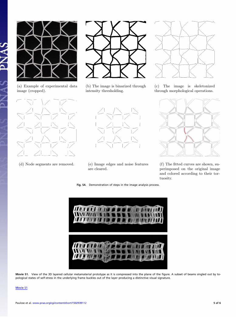
Fig. S4. Demonstration of steps in the image analysis process.
Movie S1. View of the 3D layered cellular metamaterial prototype as it is compressed into the plane of the figure. A subset of beams singled out by to-pological states of self-stress in the underlying frame buckles out of the layer producing a distinctive visual signature.
Movie S1
Paulose et al. www.pnas.org/cgi/content/short/1502939112 5 of 6
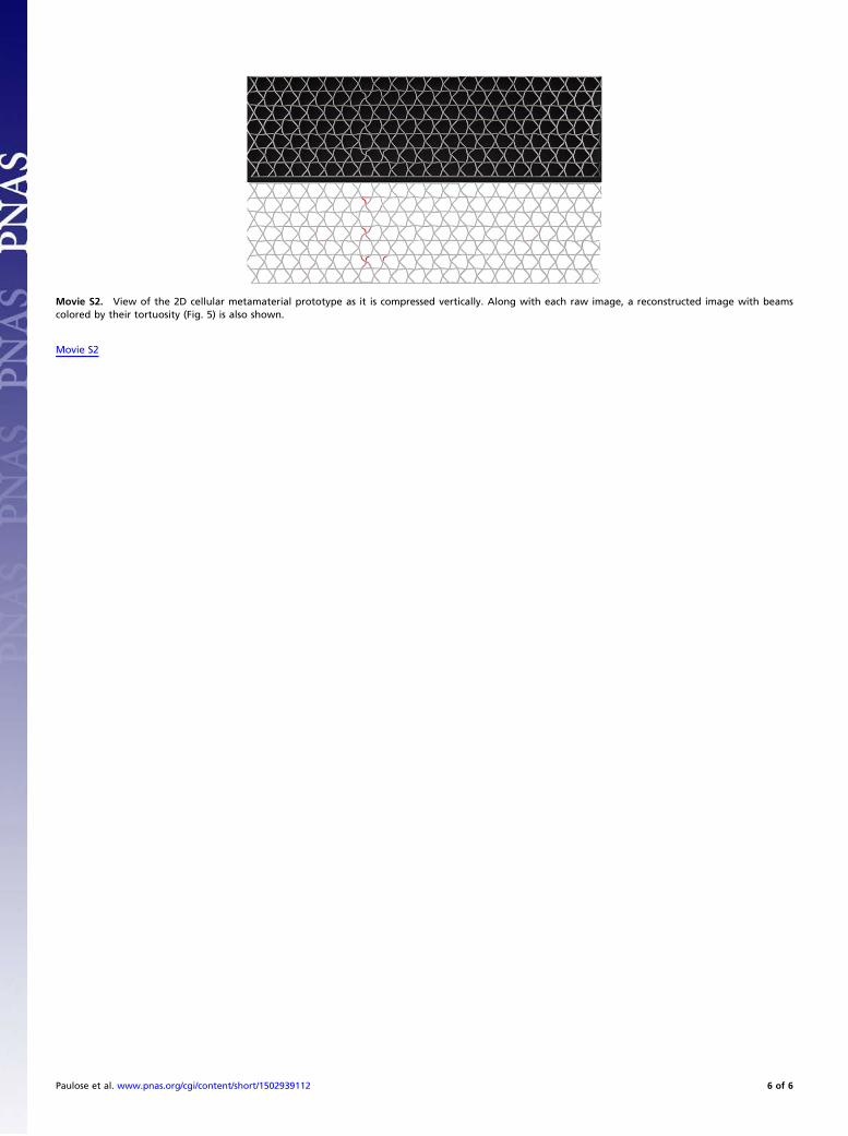
Movie S2. View of the 2D cellular metamaterial prototype as it is compressed vertically. Along with each raw image, a reconstructed image with beamscolored by their tortuosity (Fig. 5) is also shown.
Movie S2
Paulose et al. www.pnas.org/cgi/content/short/1502939112 6 of 6