selective area laser deposition joining of aluminum...
TRANSCRIPT

Selective Area Laser Deposition Joining of Aluminum Oxide
Clayton Weiss, Harris Marcus
Institute of Materials Science, University of Connecticut, Storrs, CT 06269 Accepted August 16th 2013
Abstract
Selective area laser deposition (SALD) is a chemical vapor deposition technique used to deposit ceramic material. The technique allows localized deposition in the area of the laser spot; complex depositions can be achieved through the use of a computer control program. It is possible to free form fabricate arbitrary shapes. In particular by defining the space between two work pieces as the envelope for deposition, it is possible to form a monolithic joint. The use of a trimethylaluminum and diethyl ether precursor system is explored as a means of depositing aluminum oxide. The alumina is used as joint fill material for alumina SALD joining.
Introduction
Selective area laser deposition (SALD) is a type of localized chemical vapor deposition
where the driving force for deposition comes from the heat of a laser spot. The process is pyrolytic, decomposing gas phase precursors to form solid deposits where the laser has heated a substrate. The process is computer controlled; laser power, spot position and velocity can be controlled. Arbitrary deposition patterns can be created allowing the process to be used as a means of solid freeform fabrication of ceramic materials [1]. If the shape of the deposit is programed to be the negative space between two work pieces, it is possible to form a joint between two substrates through additive manufacturing means. In a process analogous to welding two work pieces are joined with a filler material of the same chemical composition. Unlike welding, the fill material is deposited in-situ as a byproduct of a chemical reaction in the joint space, as apposed to being derived from melted external stock. This allows materials to be joined that have extremely high melting temperatures or that do not form a liquid phase. The solid freeform technique Selective Area Laser Deposition (SALD) has been used as a means of joining ceramic work pieces with a monolithic and chemically homogenous ceramic fill material. Silicon carbide and Silicon nitride have been demonstrated [2][3][4]. The deposition of an oxide material would further demonstrate the versatility of the process.
In order to deposit an oxide material such as aluminum oxide (Al2O3) it is first necessary to establish a viable precursor. The SALD process uses volatile liquids of gaseous precursors that are the source of the constituent elements of the ceramic deposit. For the case of alumina, sources of both aluminum and oxygen are necessary. As a chemical vapor deposition process, the SALD precursors have similar requirements to those used in conventional Chemical Vapor Deposition, CVD, volatility, gas state stability and the potential for controlled decomposition. As the SALD process is a laser driven process, the decomposition reaction environment can be more hostile. High temperature gradients can exist between the laser-induced thermal zone and the surrounding ambient temperature substrates. The laser interaction with the substrate also serves to create a reactive plasma. Since there is a high, localized, temperature and reactive plasma the reaction rate can occur more rapidly than conventional CVD if there is a high enough
514

reactant flux into the reaction zone. A SALD precursor must have a high enough vapor pressure to create bulk deposits on a feasible time scale.
Alumina CVD precursors exist that are suitable for conventional CVD but less so for SALD growth. Aluminum Chloride must be heated to a temperature >150° C to produce a workable vapor pressure, and must be kept at an elevated temperature for the duration of the experiment to prevent condensation [5]. The solid-state precursors also produce a vapor that is best delivered by carrier gas [6]. The SALD deposition system is not configured for this type of delivery. Other solid state aluminum precursors such as aluminum acetylacetonate, Al(C5H7O2)3, have the advantage of containing oxygen so have the potential of being single source precursors. The material is a solid so would have to be heated to >190° C for a usable vapor pressure [5].
Metal organic precursors, specifically aluminum alkyls such as trimethylaluminum or TMA, Al(CH3)3 are potential precursors. TMA is a volatile aluminum source that has been used as an aluminum source both for pure Al deposits and as the aluminum constituent of Al2O3[7]. TMA is a similar metal bearing alkyl to tetramethylsilane TMS, Si(CH3)4, which has been used with success for the SALD deposition of silicon carbide and other such compounds are frequently used in other CVD systems [6]. TMA is pyrophoric and highly reactive with a variety of oxygen sources so special handling apparatus’ are necessary as well as a carefully chosen oxygen source.
Alumina deposition with TMA requires an oxygen source. TMA is highly reactive with O2, and will react in the gas phase. Water vapor and hydrogen peroxide vapor have been used as oxygen sources for alumina but are too reactive for SALD type deposits, as previous studies have shown [8]. Low concentrations of the oxidizing gas could be used to form small amounts of alumina but the resulting reaction is too low yield for the SALD process and increased gas concentration results in spontaneous decomposition.
In order to find a precursor that would not cause spontaneous decomposition in the gas phase, different sources of oxygen were explored. There are organic gasses that are volatile, contain oxygen and have potentially high vapor pressures. Ethers contain oxygen centrally bonded to two alkyl or aryl groups. These chemicals are highly volatile and are stable in their gaseous state. Ethers have been used as oxygen sources for CVD reactions with metal organic gasses and have not resulted in spontaneous decomposition [9]. Ethers have the additional characteristic in the gas phase of potentially forming gas phase complexes with metal organic gasses [10]. Due to the availability and high vapor pressure of diethyl ether, it was chosen over a variety of other ethers and tert-butyl ethers for this study. Diethyl ether has a vapor pressure of 400 torr at room temperature. This vapor pressure is higher than necessary for the SALD process.
To make alumina Diethyl ether, C4H10O and TMA were chosen as the active precursors. A stoiciometrically-balanced equation for a potential decomposition reaction is shown below:
2(Al(CH3)3)g + 3(C4H10O)g +12(H2)g ⟹ Al2O3s + 18 (CH4)g
515

Hydrogen is added to provide the full conversion of the C and H to gaseous methane. This formula was the basis of the gas composition used for the deposition experiments.
The procedure normally followed for the SALD deposition had to be somewhat modified for the above precursor combination. The vacuum chamber used for the deposition experiments is evacuated and back filled with argon or helium 5 times and the whole system is pumped down to <100 mtorr. From this evacuated state, the chamber is filled with the reactive gasses, then inert gas, and the total pressure is kept as a partial vacuum. The gasses are introduced into the reaction chamber and the total chamber pressure is monitored by a diaphragm vacuum gauge. This pressure can normally be read as directly correlating with total gas quantity. This is a good measure of the added gas quantities as long as the gas does not react in the gas phase. The combination TMA and ether into a clean and evacuated reaction chamber does not result in spontaneous decomposition, which would be indicated by the formation of alumina powder appearing as white smoke. Instead, a pressure change is observed with no apparent decomposition. TMA has an equilibrium vapor pressure of 8.6 torr at 20° C found from the equation; Log P(mmHg) = 8.22-2134.8/T(K) [5]. In the deposition process it is important to prevent the pressure from exceeding this point with in the vacuum chamber because condensation will occur on the chamber walls. When 6 torr of TMA is added to the reaction chamber first, then ether is slowly added, there is an observed pressure drop to 3 torr at which point the pressure begins to rise. The effect is repeatable and potentially indicates the formation of a gas phase complex of the two reactants. The effect is observed when the first gas introduced is ether and the second gas is TMA. In this case a pressure drop is observed but without subsequent pressure increase and eventual visible condensation on the reaction window. The gas mixture is then used as a source of both aluminum and oxygen during the decomposition process.
The experimental deposition system is set up to perform SALD depositions. The system consists of a Labview computer control program that controls the power of the laser and the motion of an X-Y optics positioning stage. The optical train positions the beam above the desired section of substrate and a focusing lens converges the beam. The laser enters into the reaction chamber through a viewport and the focused beam hits the substrate and substrate holder. The substrates for these alumina depositions are titanium disks, alumina disks, and alumina beveled work pieces. The titanium disk is used as a deposition substrate so that the purity of the alumina can be confirmed independent of an alumina substrate. Alumina disk substrates were used to show the adherence of the deposited material to a like substrate. The flat beveled substrates were used to demonstrate the potential for joining alumina to alumina with an alumina joint fill.
Experimental Materials and Methods
The deposition and joining experiments were designed to test a variety of experimental
conditions. Each deposition uses a combination of laser power, scan speed, and spot size to create a localized heat zone that drives the decomposition reaction. The chemical composition the gas precursor mixture is also varied. The deposition pattern is varied with respect to the final desired shape, in the case of joining; the deposition pattern is customized according to the joint width and length.
516
Laser power variations include: 10, 15, 20, 30, 35, 45, 60 and 70 W. Depositions that occurred above 45 W were to energetic for controllable depositions and resulted in run away growth, gas phase decomposition, and window contamination. The scan speed variations include: 10, 15, 30, 45, 50, 90, 100, 150, 175, 360 micron/s. The scan speeds of ≤ 15 resulted in excess heating of the viewport resulting in contamination through decomposition or partial decomposition. Scan speeds above 170 µm/s resulted in uneven decomposition and would require excessively high laser power. Laser spot size was fixed at 150 microns achieved through a combination of fixed focal length lens, and a defocus of 10 mm below the work piece surface.
The precursors used in the deposition experiments are TMA, diethyl ether, H2 and inert argon. Due to the previously described pressure reduction effect it is not possible to fully define the ratio of TMA to ether. A method was devised for introducing these gasses into the vacuum chamber. TMA or ether is introduced first to one quarter the desired final pressure the other gas is then introduced allowing the pressure to drop then equalize. This process is repeated 4 times and the mixed gasses are brought to the desired pressure. In this way a slow gas phase mixing was allowed and the gas phase reaction remained stable. If the first gas introduced is TMA the mixing is terminated below the 8 torr mark. Additional ether can be added beyond this point to increase the availability of oxygen in the system. If the ether is added first the pressure can be incremented to 24 torr for the mixed gas final pressure. Beyond this point TMA addition does not increase the total pressure without resulting in condensation. Additional Hydrogen is added to the system in 25, 80, 96, 100, 120 and 200 torr quantities. And the concentrations of Ar used are 50, 80, 100, 120, 192 torr.
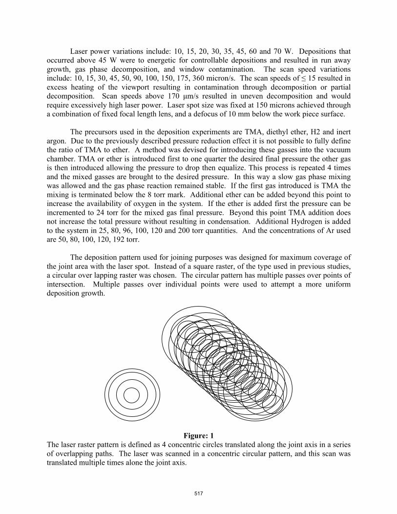
The deposition pattern used for joining purposes was designed for maximum coverage of the joint area with the laser spot. Instead of a square raster, of the type used in previous studies, a circular over lapping raster was chosen. The circular pattern has multiple passes over points of intersection. Multiple passes over individual points were used to attempt a more uniform deposition growth.
Figure: 1 The laser raster pattern is defined as 4 concentric circles translated along the joint axis in a series of overlapping paths. The laser was scanned in a concentric circular pattern, and this scan was translated multiple times alone the joint axis.
517

Joining experiments were performed on solid substrates with two beveled work pieces nearly abutting off set from the substrate below by carbon tape. The carbon tape affixed the work pieces during the joining process and allowed a small gap for reactive gasses to diffuse to the underside of the joint during deposition. Al2O3 deposits were made with the objective of joining two alumina substrates with an alumina joint fill. Utilizing a chemical precursor combination of TMA, ether, H2 and Ar, samples were tested with an aim of showing that alumina can be a deposition product. A typical, representative deposition was performed under the following conditions: TMA was introduced into an evacuated reaction chamber. 2 torr of TMA was added, then 2 torr of ether. The process was repeated until the total pressure remained stable after the last addition of TMA. An ether over-pressure was added bringing the pressure from 30 torr to 58 torr. 96 torr of H2 was added. The scan speed was 30 microns/s with a laser power of 15 W
518

Experimental Results . A SEM micrograph of a typical alumina deposit is shown below:
Figure: 2
The surface morphology of an alumina deposition test deposit is shown at two magnifications. The deposited material is polycrystalline, with several smaller grains coalescing to round grain clusters these clusters then forming a dense bulk structure. Shown below is Energy Dispersive X-ray Spectroscopy, EDS, elemental analysis of area approximately 50 microns across, which indicates the elemental constituents of oxygen and aluminum. Gold spectrum indicates the presence of a conductive sputter coating.
EDS chemical analysis indicates a 42 atomic percent Al, and 55 atomic percent Oxygen, which would be 40 and 60 % in the stoichiometric case.
Pure alumina is white and the deposited material resulting from the TMA-ether chemistry has a grey to black color. The black color most probably indicates a carbon contamination in the alumina; however, this carbon does not exist, as a measurable second phase so is likely a lattice scale defect or part of an amorphous constituent.
519

To test the theory of carbon contamination in the crystal lattice a sample joint was placed in a furnace for two days at 1000° C. It was predicted that the black deposit would turn white after the carbon had a chance to diffuse out.
Figure: 3 A joint fill was deposited between two beveled and abutting pieces of aluminum oxide. The joint material deposited was black during the experiment. A heat treatment was performed and the deposited material turned white. X-ray diffraction was performed before and after the heat treatment, shown below:
520
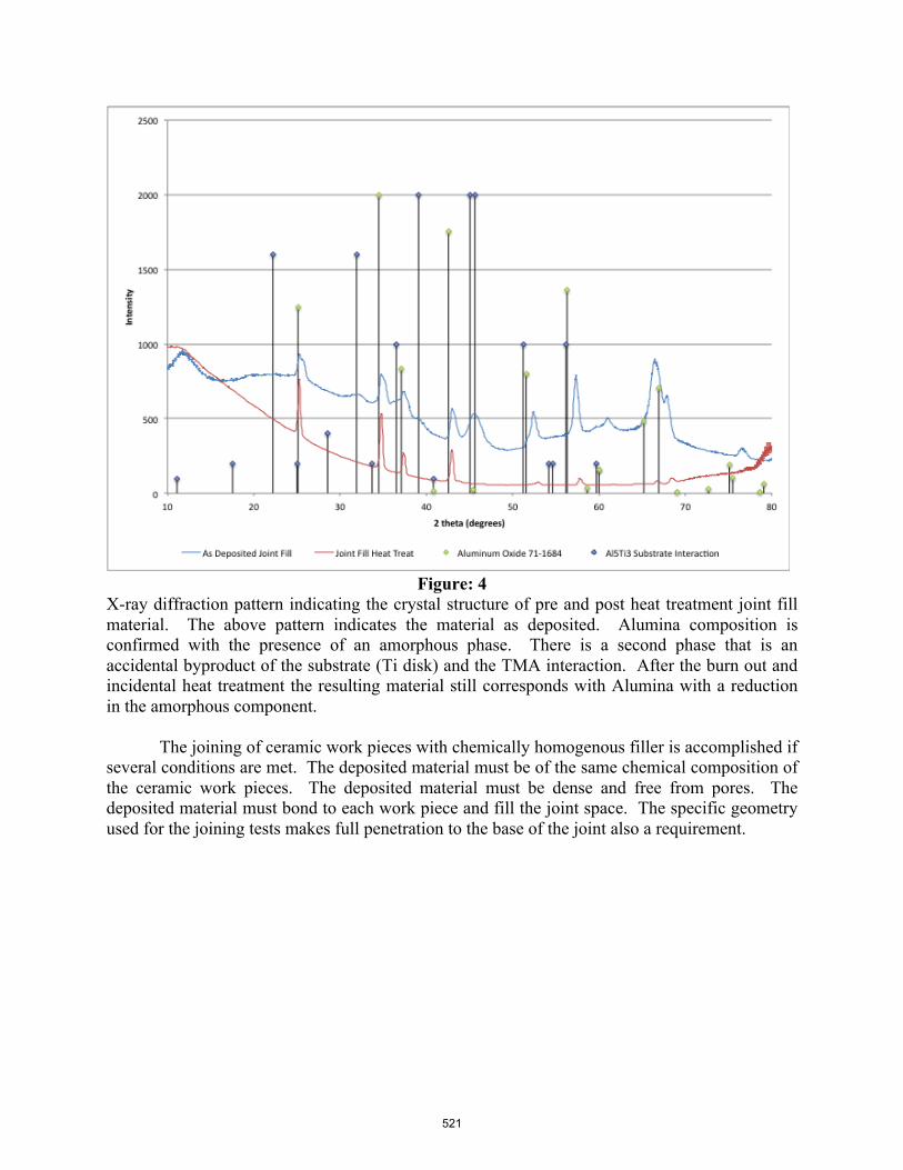
Figure: 4
X-ray diffraction pattern indicating the crystal structure of pre and post heat treatment joint fill material. The above pattern indicates the material as deposited. Alumina composition is confirmed with the presence of an amorphous phase. There is a second phase that is an accidental byproduct of the substrate (Ti disk) and the TMA interaction. After the burn out and incidental heat treatment the resulting material still corresponds with Alumina with a reduction in the amorphous component.
The joining of ceramic work pieces with chemically homogenous filler is accomplished if several conditions are met. The deposited material must be of the same chemical composition of the ceramic work pieces. The deposited material must be dense and free from pores. The deposited material must bond to each work piece and fill the joint space. The specific geometry used for the joining tests makes full penetration to the base of the joint also a requirement.
521

Figure: 5 The condition of adhesion between substrate and deposited material is shown. The left image shows the interface between material deposited at the top of a beveled joint and the substrate. A magnified image, right, indicates a pore free interface where the substrate is on the left and the deposited material is on the right. Grains of deposited material of the same order of magnitude as the substrate are seen growing from the substrate surface. Smaller grains are seen in the bulk deposit approximately 25 microns from the surface of the substrate. In all figures, A indicates the alumina substrate, B indicates laser deposited alumina, and C indicates mounting compound.
The geometry of the joint and the growth mechanisms of the deposited material resulted in difficulty achieving full joint penetration, and wall adhesion.
Figure: 6 A joint between two alumina semicircular disks with beveled edges is shown in the left micrograph. Growth has occurred from each work piece face. The deposited material grew toward the center but ultimately resulted in the closing off of the beam pathway. The partial penetration into the base of the joining work piece is shown to the right.
A
B C
A
B
A
B C
2.5 mm
A
B C
522

Figure: 7 The micrographs above indicate a joint between two alumina substrates joined with an alumina deposit. The top two micrographs represent the top and bottom of the joint at low magnification. A relatively full joint is observed with low porosity. The joint does suffer from delamination from the substrate walls potentially due to a thermal mismatch between the substrate and the bulk deposit. Shown below are examples of the deposition fill at the base of a joint. The left image indicates a deposit fully penetrating the joint. The right micrograph indicates full penetration with partial delamination.
A
A
A A
A
A
A
B
B
B
B
C
C
C C
C
523

Conclusion
The SALD process shows potential for joining ceramic oxides by using aluminum oxide as a test case. A precursor that consistently yields alumina on decomposition was chosen and chemical and crystal structure analyses were performed of the deposition product. Joints were formed between alumina substrates with an alumina joint fill. The quality of the deposit and the interface were examined. Deposits that initially appeared black as deposited were converted to a pure white alumina without large volumetric or porosity changes. Though the process could be improved, SALD has potential for joining of oxides and other classes of ceramic material if the correct precursors and experimental conditions are chosen. References [1] P. Calvert, R. Crockett, “Chemical Solid Free-Form Fabrication: Making Shapes without Molds,” Chem. Mater. 1997, 9, 650-663 [2] S.L. Harrison, H. L. Marcus, “Gas-phase Selective Area Laser Deposition SALD/ joining of SiC,” Materials and Design 20 ,1999. pp 147-152 [3] C. M. Weiss, M. Aindow, H. Marcus, “Ceramic Joining by Gas Phase Pulsed Laser Processing,” Solid Freeform Fabrication Proceedings, The University of Texas Austin, (2009) [4] Weiss, C.M., Marcus, H., “Selective Area Laser Deposition for Silicon Nitride Joining,” Solid Freeform Fabrication Proceedings, The University of Texas Austin, (2012) [5] Sigma Aldrich, http://www.sigmaaldrich.com/ and MSDS sheets [6] H.O. Pierson, Handbook of Chemical Vapor Deposition, Elsevier, 1999 [7] D.N. Goldstein , et al., “Al2O3 Atomic Layer Deposition with Trimethylaluminum and Ozone Studied by in Situ Transmission FTIR Spectroscopy and Quadrupole Mass Spectrometry,” Journal of Physical Chemistry. 112, 2008, pp. 19530-19539 [8] C. M. Weiss, H.L. Marcus, “Al2O3 Precursor Evaluation for SALD Joining," Proceedings of the Solid Freeform Fabrication Symposium, The University of Texas at Austin (2010) [9] Y. Hirose, Y. Terasawa, Synthesis of Diamond Thin Films by Thermal CVD Using Organic Compounds, Japanese Journal of Applied Physics, Vol. 25, No. 6, 1986 pp. L519-L521 [10] S. Maleknia J. Brodbelt, “Gas-Phase Selectivities of Crown Ethers for Alkali Metal Ion Complexation,” J. Am. Chem. SOC. 1992, 114, 4295-4298
524