selection guide for encoders - · pdf fileselection guide for encoders. ... entering the...
TRANSCRIPT
Selection Guide for Encoders
This document guides you to find the right encoder for your application.
SE
LE
CTI
ON
AID
We raise the relevant questions and give the appropriate answers.
Very often the differences between two encoders seem to be marginal. With the help of this document you are in the position to find these differences quickly and easily enabling you to choose the right encoder product family.
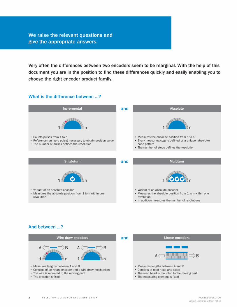
What is the difference between ...?
And between ...?
Incremental and Absolute
• Counts pulses from 1 to n• Reference run (zero pulse) necessary to obtain position value• The number of pulses defines the resolution
• Measures the absolute position from 1 to n• Every measuring step is defined by a unique (absolute)
code pattern• The number of steps defines the resolution
Singleturn and Multiturn
• Variant of an absolute encoder• Measures the absolute position from 1 to n within one
revolution
• Variant of an absolute encoder• Measures the absolute position from 1 to n within one
revolution• In addition measures the number of revolutions
Wire draw encoders and Linear encoders
• Measures lengths between A and B• Consists of an rotary encoder and a wire draw mechanism• The wire is mounted to the moving part• The encoder is fixed
• Measures lengths between A and B• Consists of read head and scale• The read head is mounted to the moving part• The measuring element is fixed
7028292/2013.07.26Subject to change without notice
2 S E L E C T I O N G u I D E f O r E N C O D E r S | S I C K
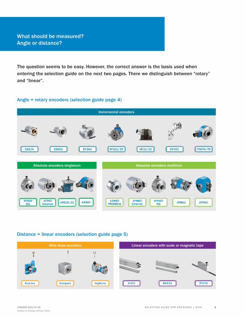
What should be measured?Angle or distance?
The question seems to be easy. However, the correct answer is the basis used when entering the selection guide on the next two pages. There we distinguish between “rotary” and “linear”.
Angle = rotary encoders (selection guide page 4)
Distance = linear encoders (selection guide page 5)
Absolute encoders singleturn
AFS60 SSI ARS60AFS60
Ethernet
Linear encoders with scale or magnetic tape
KH53 KH53A TTK70
Wire draw encoders
EcoLine Compact HighLine
DBS36 DBS50 DFS60 DFS20/25 HD32/52 DFV60 DGS34/35
Incremental encoders
A3M60 PROFIBUS
AFM60 SSI ATM60 ATM90
Absolute encoders multiturn
AFM60 EthernetARS20/25
S E L E C T I O N G u I D E f O r E N C O D E r S | S I C K7028292/2013.07.26Subject to change without notice
3
Incrementalencoders
Absolute encoders singleturn
Absolute encoders multiturn
DBS
36
DBS
50
DfS
60
DfV
60
DG
S34/
35
DfS
2x
HD
52
HD
32
AfS6
0
ArS6
0
ArS2
0/25
A3M
60
AfM
60
ATM
60
ATM
90
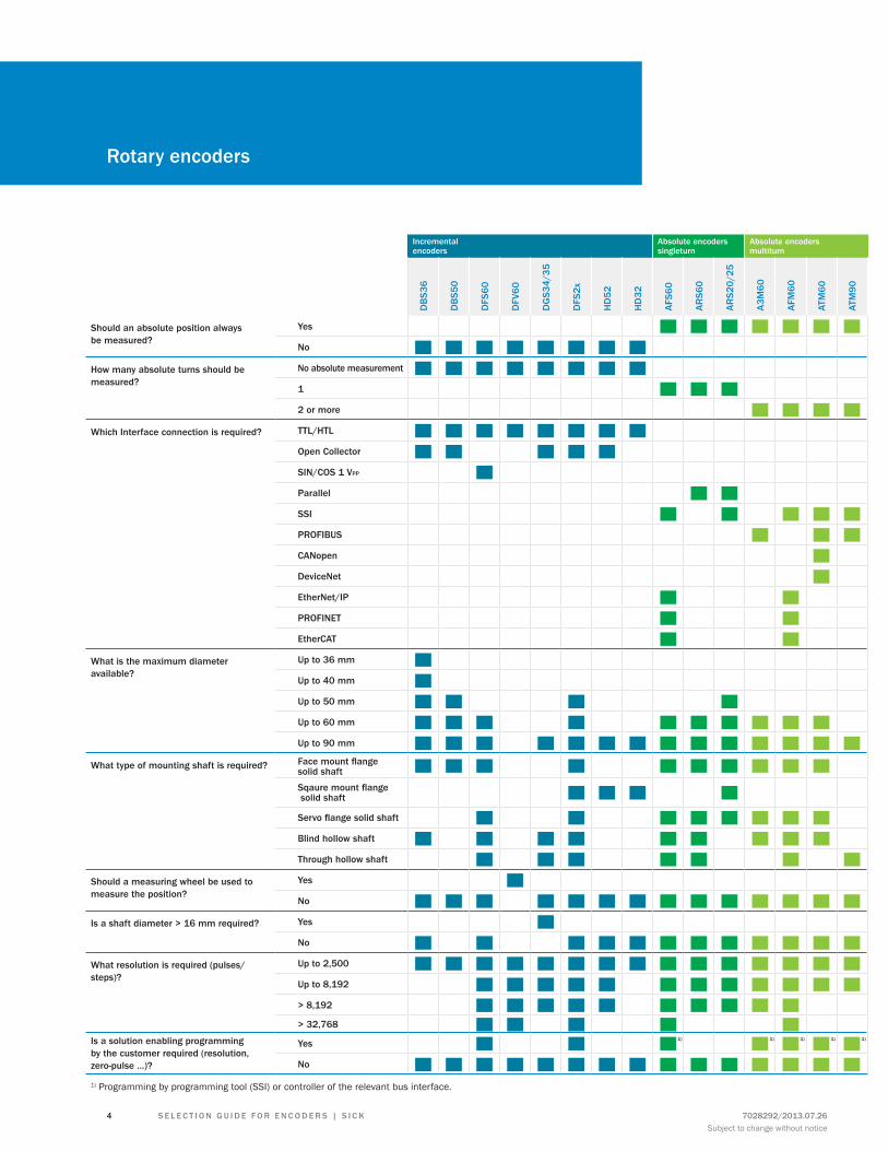
Should an absolute position always be measured?
Yes ■ ■ ■ ■ ■ ■ ■No ■ ■ ■ ■ ■ ■ ■ ■
How many absolute turns should be measured?
No absolute measurement ■ ■ ■ ■ ■ ■ ■ ■1 ■ ■ ■2 or more ■ ■ ■ ■
Which Interface connection is required? TTL/HTL ■ ■ ■ ■ ■ ■ ■ ■Open Collector ■ ■ ■ ■ ■SIN/COS 1 VPP ■Parallel ■ ■SSI ■ ■ ■ ■ ■PrOfIBuS ■ ■ ■CANopen ■DeviceNet ■EtherNet/IP ■ ■PrOfINET ■ ■EtherCAT ■ ■
What is the maximum diameter available?
up to 36 mm ■up to 40 mm ■up to 50 mm ■ ■ ■ ■up to 60 mm ■ ■ ■ ■ ■ ■ ■ ■ ■ ■up to 90 mm ■ ■ ■ ■ ■ ■ ■ ■ ■ ■ ■ ■ ■ ■
What type of mounting shaft is required? Face mount flange solid shaft ■ ■ ■ ■ ■ ■ ■ ■ ■ ■Sqaure mount flange solid shaft ■ ■ ■ ■Servo flange solid shaft ■ ■ ■ ■ ■ ■ ■ ■Blind hollow shaft ■ ■ ■ ■ ■ ■ ■ ■ ■Through hollow shaft ■ ■ ■ ■ ■ ■ ■
Should a measuring wheel be used to measure the position?
Yes ■No ■ ■ ■ ■ ■ ■ ■ ■ ■ ■ ■ ■ ■ ■
Is a shaft diameter > 16 mm required? Yes ■No ■ ■ ■ ■ ■ ■ ■ ■ ■ ■ ■ ■
What resolution is required (pulses/steps)?
up to 2,500 ■ ■ ■ ■ ■ ■ ■ ■ ■ ■ ■ ■ ■ ■ ■up to 8,192 ■ ■ ■ ■ ■ ■ ■ ■ ■ ■ ■ ■> 8,192 ■ ■ ■ ■ ■ ■ ■ ■ ■ ■> 32,768 ■ ■ ■ ■ ■
Is a solution enabling programming by the customer required (resolution, zero-pulse …)?
Yes ■ ■ ■1) ■1) ■1) ■1) ■1)
No ■ ■ ■ ■ ■ ■ ■ ■ ■ ■ ■ ■ ■ ■ ■1) Programming by programming tool (SSI) or controller of the relevant bus interface.
rotary encoders
7028292/2013.07.26Subject to change without notice
4 S E L E C T I O N G u I D E f O r E N C O D E r S | S I C K
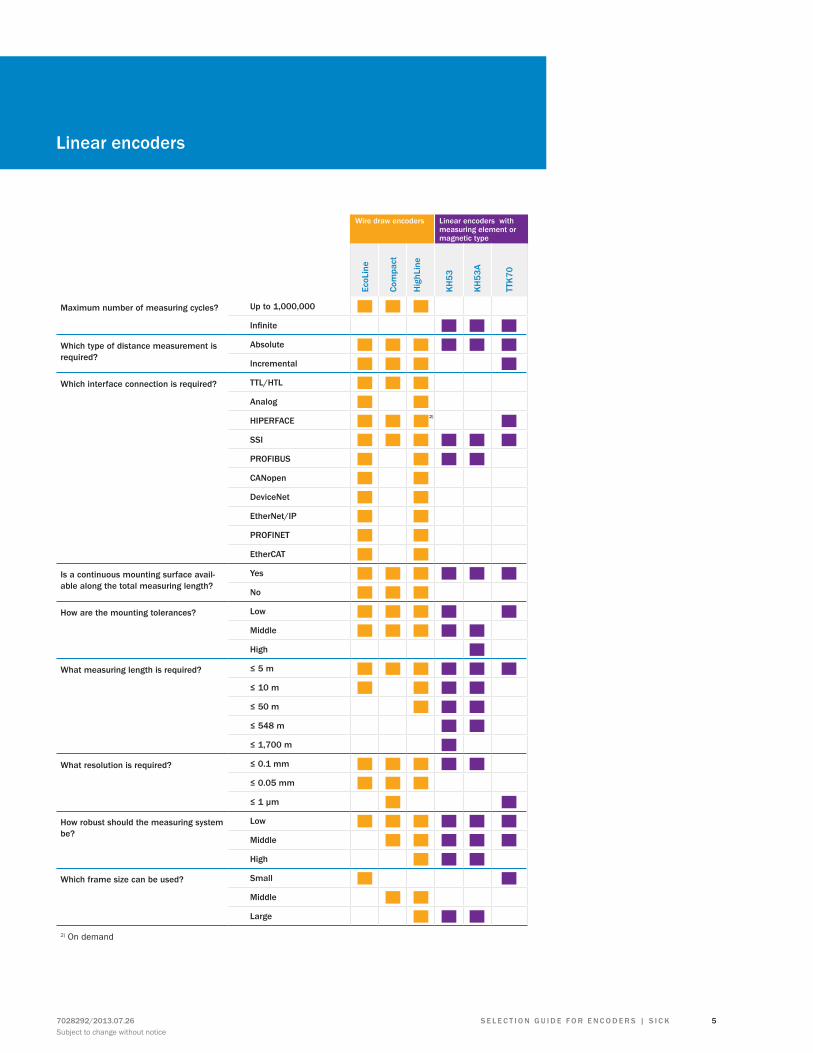
Wire draw encoders Linear encoders with measuring element or magnetic type
EcoL
ine
Com
pact
Hig
hLin
e
KH53
KH53
A
TTK7
0
Maximum number of measuring cycles? up to 1,000,000 ■ ■ ■Infinite ■ ■ ■
Which type of distance measurement is required?
Absolute ■ ■ ■ ■ ■ ■Incremental ■ ■ ■ ■
Which interface connection is required? TTL/HTL ■ ■ ■Analog ■ ■HIPErfACE ■ ■ ■2) ■SSI ■ ■ ■ ■ ■ ■PrOfIBuS ■ ■ ■ ■CANopen ■ ■DeviceNet ■ ■EtherNet/IP ■ ■PrOfINET ■ ■EtherCAT ■ ■
Is a continuous mounting surface avail-able along the total measuring length?
Yes ■ ■ ■ ■ ■ ■No ■ ■ ■
How are the mounting tolerances? Low ■ ■ ■ ■ ■Middle ■ ■ ■ ■ ■High ■
What measuring length is required? ≤ 5 m ■ ■ ■ ■ ■ ■≤ 10 m ■ ■ ■ ■≤ 50 m ■ ■ ■≤ 548 m ■ ■≤ 1,700 m ■
What resolution is required? ≤ 0.1 mm ■ ■ ■ ■ ■≤ 0.05 mm ■ ■ ■≤ 1 µm ■ ■
How robust should the measuring system be?
Low ■ ■ ■ ■ ■ ■Middle ■ ■ ■ ■ ■High ■ ■ ■
Which frame size can be used? Small ■ ■Middle ■ ■Large ■ ■ ■
2) On demand
Linear encoders
S E L E C T I O N G u I D E f O r E N C O D E r S | S I C K7028292/2013.07.26Subject to change without notice
5
A
Analog interfaceStandard analog interface: As required from 4 to 20 mA, or 0 to 10 V output signal.
B
Baud rateGives the signal rate and hence the speed of serial data trans-fer in bits per second.
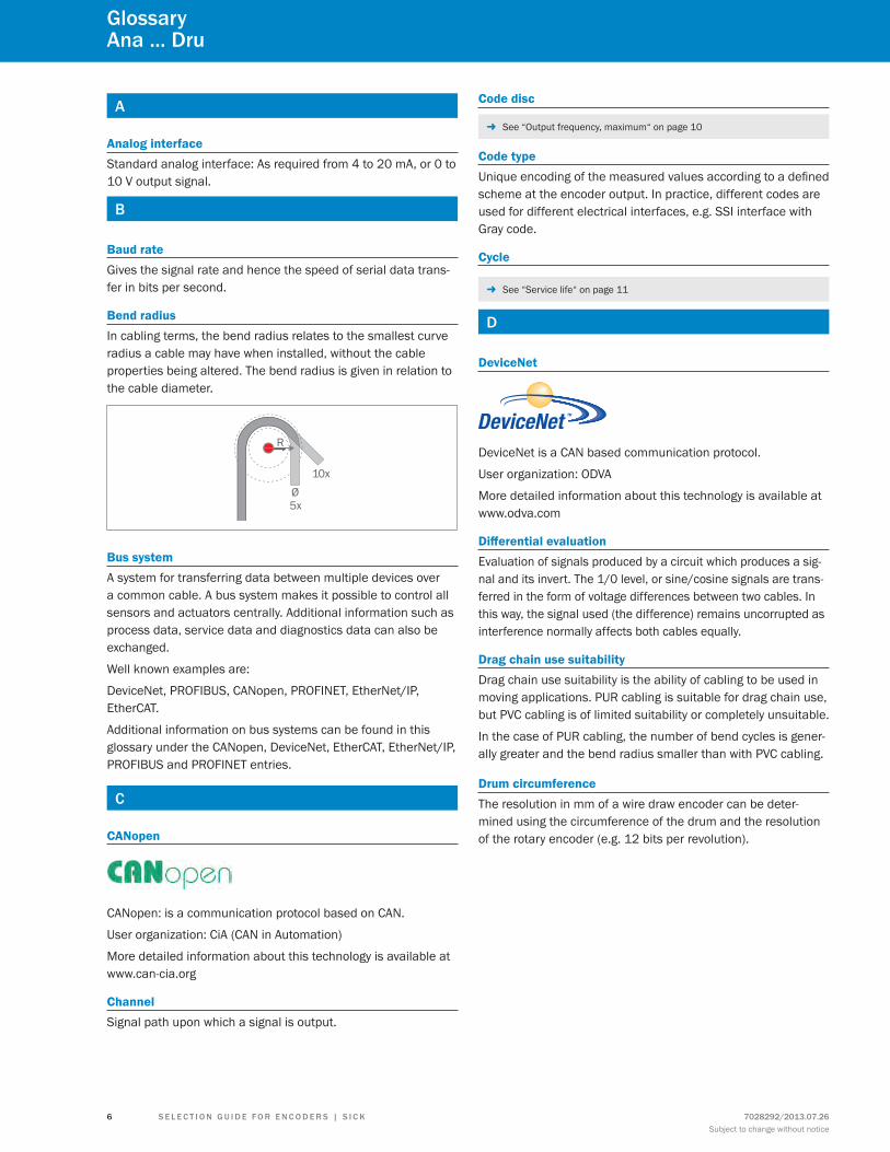
Bend radiusIn cabling terms, the bend radius relates to the smallest curve radius a cable may have when installed, without the cable properties being altered. The bend radius is given in relation to the cable diameter.
5x
10x
Bus systemA system for transferring data between multiple devices over a common cable. A bus system makes it possible to control all sensors and actuators centrally. Additional information such as process data, service data and diagnostics data can also be exchanged.
Well known examples are:
DeviceNet, PROFIBUS, CANopen, PROFINET, EtherNet/IP, EtherCAT.
Additional information on bus systems can be found in this glossary under the CANopen, DeviceNet, EtherCAT, EtherNet/IP, PROFIBUS and PROFINET entries.
C
CANopen
CANopen: is a communication protocol based on CAN.
User organization: CiA (CAN in Automation)
More detailed information about this technology is available at www.can-cia.org
ChannelSignal path upon which a signal is output.
Code disc
- See “Output frequency, maximum“ on page 10
Code typeUnique encoding of the measured values according to a defined scheme at the encoder output. In practice, different codes are used for different electrical interfaces, e.g. SSI interface with Gray code.
Cycle
- See “Service life“ on page 11
D
DeviceNet
DeviceNet is a CAN based communication protocol.
User organization: ODVA
More detailed information about this technology is available at www.odva.com
Differential evaluationEvaluation of signals produced by a circuit which produces a sig-nal and its invert. The 1/0 level, or sine/cosine signals are trans-ferred in the form of voltage differences between two cables. In this way, the signal used (the difference) remains uncorrupted as interference normally affects both cables equally.
Drag chain use suitabilityDrag chain use suitability is the ability of cabling to be used in moving applications. PUR cabling is suitable for drag chain use, but PVC cabling is of limited suitability or completely unsuitable.
In the case of PUR cabling, the number of bend cycles is gener-ally greater and the bend radius smaller than with PVC cabling.
Drum circumferenceThe resolution in mm of a wire draw encoder can be deter-mined using the circumference of the drum and the resolution of the rotary encoder (e.g. 12 bits per revolution).
GlossaryAna ... Dru
7028292/2013.07.26Subject to change without notice
6 S E L E C T I O N G u I D E f O r E N C O D E r S | S I C K
E
EMCElectromagnetic compatibility (EMC) means that technical equipment should not be affected by electromagnetic interfer-ence. This is achieved both by limiting sources of interference in devices and by devices being designed to be sufficiently resistant to interference. EMC is regulated by EU Directives and Standards.
Enclosure ratingThe enclosure rating indicates the degree of protection of a machine or sensor against contact and penetration by impuri-ties and water. The enclosure ratings begin with the letters IP, followed by the first digit, which indicates the degree of protec-tion provided against touch and particles. The second digit describes the protection against penetration by water.
EncodersEncoders are sensors for monitoring position, angle and speed. Essentially, encoders can be categorized as rotary or linear. Rotary encoders are sub-divided into incremental and absolute encoders. Linear encoders are further sub-divided into wire draw encoders and non-contact linear encoders.
Encoders, absoluteAbsolute encoders generate information relating to position, angle and rotation counts in type-specific angle steps. For this, a unique code pattern is assigned to each angle step. The num-ber of code patterns available per revolution determines the resolution. Each code pattern forms a unique reference, and is therefore absolute position information. There is therefore no need for a reference run after switching on. A singleturn encoder measures the absolute position within a revolution. A multiturn encoder not only provides the position within a revolution but also the number of revolutions.
Encoders, incrementalIncremental encoders generate information related to position, angle and number of rotations. The number of lines per revolu-tion determines the number of impulses that the encoder trans-mits to the control unit for each revolution. The current position can be determined by the control unit counting these impulses from a reference point. When the machine is switched on, a reference run to the reference point is required to determine the actual position of the encoder.
Error limitThe error limit is the largest positive or negative deviation of any angle position (absolute) or of a measured angle (incre-mental) from the true value.
EtherCAT
EtherCAT is an Ethernet based fieldbus.
User organization: EtherCAT Technology Group
More detailed information about this technology is available at www.ethercat.org
EtherNet / IP
EtherNet / IP is an Ethernet based fieldbus.
User organization: ODVA
More detailed information about this technology is available at www.odva.com
f
FieldbusBus system in the process area for direct connection of sensors and actuators that have their own intelligence. Data in digital form is transferred between sensors, actuators and control de-vices via a fieldbus. This transfer must be as rapid as possible, i.e. close to real time. For this, a fixed minimum and maximum response time must be guaranteed.
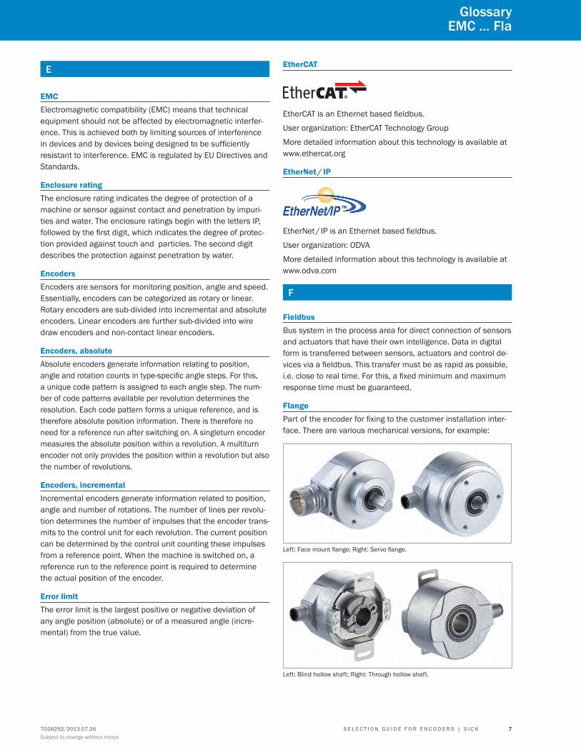
FlangePart of the encoder for fixing to the customer installation inter-face. There are various mechanical versions, for example:
Left: Face mount flange; Right: Servo flange.
Left: Blind hollow shaft; Right: Through hollow shaft.
GlossaryEMC ... fla
S E L E C T I O N G u I D E f O r E N C O D E r S | S I C K7028292/2013.07.26Subject to change without notice
7
G
Gray codeConstant code that is also used with the SSI interface. When the position value changes from one value to the next, only one data bit changes. This ensures reliable data transfer.
Gray excess codeIf a suitable section for encoder resolution is extracted from the middle of the complete Gray code, this results in the “Gray Ex-cess Code” (capped Gray code). The use of this Gray excess code allows only a single data bit to be altered even when the encoder crosses zero, although the number of steps is not 2 n where n is a whole number.
H
Halogen-free (wiring technique)Cables and wiring are said to be halogen-free if the materials used do not contain salt forming chlorine, fluorine, bromine or iodine. The insulation and sheath materials of these cables consist of polymers based on pure hydrocarbons. When such materials are burned, no corrosive or toxic gases are produced, but only water vapor and carbon dioxide.
HIPERFACE®
High Performance Interface (HIPERFACE®) is a hybrid interface developed by SICK that can transfer analog speed values and digital position values. Electrical compatibility is guaranteed by the use of HIPERFACE® as the obligatory interface for all physi-cal parameters.
The advantages of HIPERFACE® are that only one interface is required on the drive electronics for all applications, only one type of signal cabling is needed between the drive electronics and the signal encoder and manual configuration of the speed sensor is not necessary.
HIPERFACE® DSL
The High Performance Interface DSL is a pure Digital Servo Link interface developed by SICK that provides new servo drive system architecture for HIPERFACE® with a completely new range of options as it is not hybrid (analog/digital), but is completely digital.
Thanks to the innovative and interference-free HIPERFACE DSL® protocol, rugged and reliable communication can be achieved using just two wires that are integrated into the motor cable. In addition, the digital protocol requires a minimum of connection
cables between the frequency inverter and the motor feedback system.
The absence of motor feedback connections achieves signifi-cant cost savings and distinctly increased performance.
HTL push-pullHigh Voltage Transistor Logic functions with a voltage supply in the range 10 and 30 V DC, with 24 V DC being the most usual. “Low” is defined as an output of between 0 V and 3 V and “high” as between VCC and VCC - 3.5 V.
I
Interface, electricalConnection point between two devices or systems. The devices or systems on either side of an interface are connected to each other by interface cabling over which data, addresses and control signals are exchanged. The term interface embraces the complete functional, electrical and constructive conditions that make up the point of contact between the devices or systems. Depending on the type of data transfer, a distinction must be made between parallel (e.g. Centronics, IEEE 488) and serial interfaces (e.g. RS-422, RS-423, RS-485) that are designed for differing transfer speeds and distances.
Interface, mechanical
- See “Flange“ on page 7
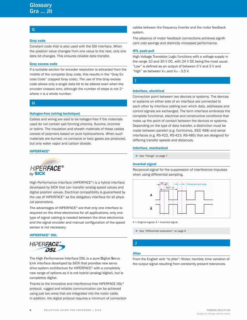
Inverted signalReciprocal signal for the suppression of interference impulses when using differential sampling.
A
A
90° el.
360° el.Measurement step
A = Original signal; Ā = Inverted signal.
- See “Differential evaluation“ on page 6
J
JitterFrom the English verb “to jitter”: flicker, tremble; time variation of the output signal resulting from constantly present tolerances.
GlossaryGra ... Jit
7028292/2013.07.26Subject to change without notice
8 S E L E C T I O N G u I D E f O r E N C O D E r S | S I C K
L
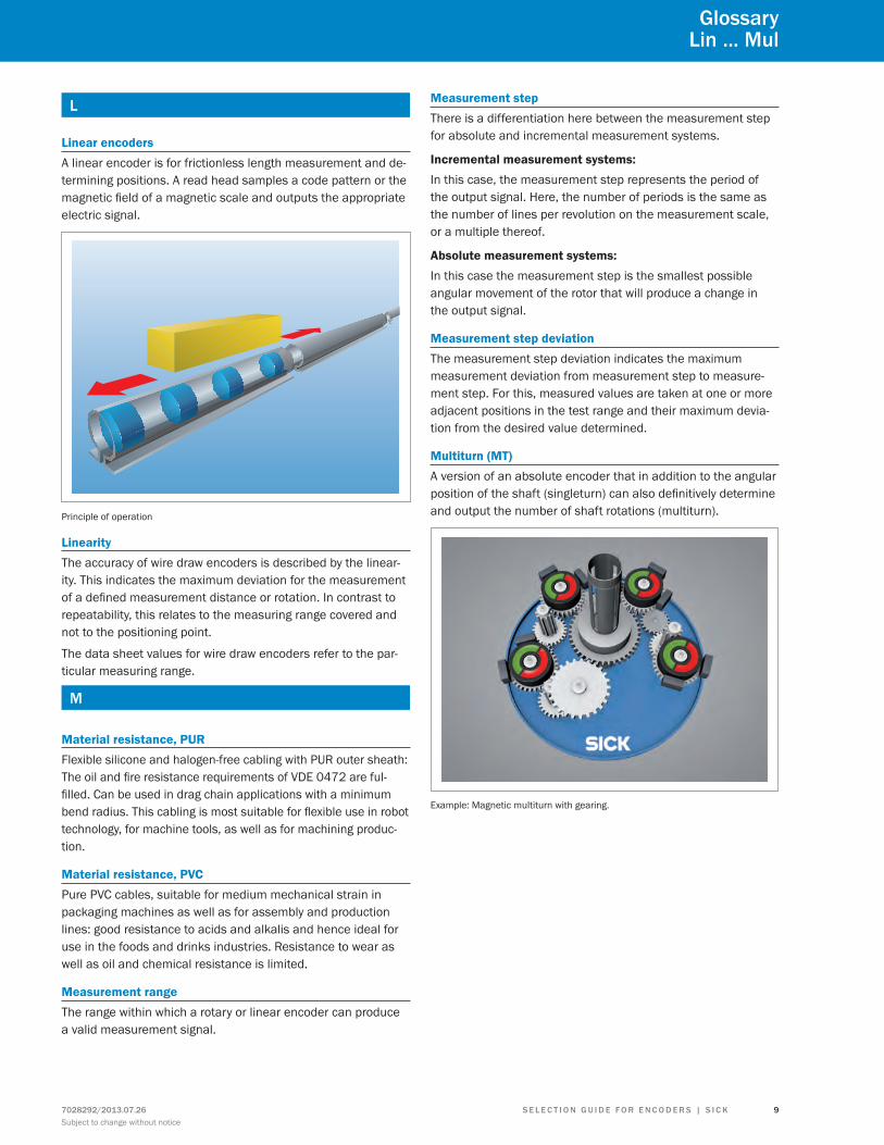
Linear encodersA linear encoder is for frictionless length measurement and de-termining positions. A read head samples a code pattern or the magnetic field of a magnetic scale and outputs the appropriate electric signal.
Principle of operation
LinearityThe accuracy of wire draw encoders is described by the linear-ity. This indicates the maximum deviation for the measurement of a defined measurement distance or rotation. In contrast to repeatability, this relates to the measuring range covered and not to the positioning point.
The data sheet values for wire draw encoders refer to the par-ticular measuring range.
M
Material resistance, PURFlexible silicone and halogen-free cabling with PUR outer sheath: The oil and fire resistance requirements of VDE 0472 are ful-filled. Can be used in drag chain applications with a minimum bend radius. This cabling is most suitable for flexible use in robot technology, for machine tools, as well as for machining produc-tion.
Material resistance, PVCPure PVC cables, suitable for medium mechanical strain in packaging machines as well as for assembly and production lines: good resistance to acids and alkalis and hence ideal for use in the foods and drinks industries. Resistance to wear as well as oil and chemical resistance is limited.
Measurement rangeThe range within which a rotary or linear encoder can produce a valid measurement signal.
Measurement stepThere is a differentiation here between the measurement step for absolute and incremental measurement systems.
Incremental measurement systems:In this case, the measurement step represents the period of the output signal. Here, the number of periods is the same as the number of lines per revolution on the measurement scale, or a multiple thereof.
Absolute measurement systems:In this case the measurement step is the smallest possible angular movement of the rotor that will produce a change in the output signal.
Measurement step deviationThe measurement step deviation indicates the maximum measurement deviation from measurement step to measure-ment step. For this, measured values are taken at one or more adjacent positions in the test range and their maximum devia-tion from the desired value determined.
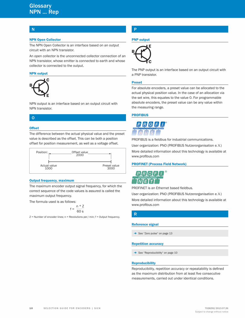
Multiturn (MT)A version of an absolute encoder that in addition to the angular position of the shaft (singleturn) can also definitively determine and output the number of shaft rotations (multiturn).
Example: Magnetic multiturn with gearing.
GlossaryLin ... Mul
S E L E C T I O N G u I D E f O r E N C O D E r S | S I C K7028292/2013.07.26Subject to change without notice
9
N
NPN Open CollectorThe NPN Open Collector is an interface based on an output circuit with an NPN transistor.
An open collector is the unconnected collector connection of an NPN transistor, whose emitter is connected to earth and whose collector is connected to the output.
NPN output
C
E
B
NPN output is an interface based on an output circuit with NPN transistor.
O
OffsetThe difference between the actual physical value and the preset value is described as the offset. This can be both a position offset for position measurement, as well as a voltage offset.
Offset value2000
Position:
Preset value3000
Actual value1000
Output frequency, maximumThe maximum encoder output signal frequency, for which the correct sequence of the code values is assured is called the maximum output frequency.
The formula used is as follows:n * Z60 sf =
Z = Number of encoder lines; n = Revolutions per / min; f = Output frequency.
P
PNP output
E
C
B
The PNP output is an interface based on an output circuit with a PNP transistor.
PresetFor absolute encoders, a preset value can be allocated to the actual physical position value. In the case of an allocation via the set wire, this equates to the value 0. For programmable absolute encoders, the preset value can be any value within the measuring range.
PROFIBUS
PROFIBUS is a fieldbus for industrial communications.
User organization: PNO (PROFIBUS Nutzerorganisation e. V.)
More detailed information about this technology is available at www.profibus.com
PROFINET (Process Field Network)
PROFINET is an Ethernet based fieldbus.
User organization: PNO (PROFIBUS Nutzerorganisation e. V.)
More detailed information about this technology is available at www.profibus.com
r
Reference signal
- See “Zero pulse“ on page 13
Repetition accuracy
- See “Reproducibility“ on page 10
ReproducibilityReproducibility, repetition accuracy or repeatability is defined as the maximum distribution from at least five consecutive measurements, carried out under identical conditions.
GlossaryNPN ... rep
7028292/2013.07.26Subject to change without notice
1 0 S E L E C T I O N G u I D E f O r E N C O D E r S | S I C K
ResolutionThe resolution is expressed as the number of impulses per revolution or path units.
Encoder type Resolution definitionRotary, incremental Resolution as number of impulsesRotary, absolute, singl-eturn
Resolution as number of steps per revolu-tion
Rotary, absolute, mul-titurn
The total resolution consists of the num-ber of steps per revolution and the num-ber of revolutions
Linear encoders Resolution in mm Special for cable pull:
Circumference of cable drumResolution for one revolution of the en-
coder
If, for example a rotary incremental encoder has a resolution of 12 bits, this means the number of impulses is 4096.
The formula for calculation is: Number of impulses = 2X, where x is the resolution in bits.
Rotation direction, clockwise (cw)Rotation to the right, when viewing the shaft.
Rotation direction, counterclockwise (ccw)Rotation to the left, when viewing the shaft.
S
Sampling frequencyThe frequency with which the signal periods of a sensor system are measured per second.
For incremental measuring systems, the speed is limited by the maximum sampling frequency.
Sampling, magneticalPosition, angle and speed determination for rotary or linear en-coders using permanent magnets and appropriate evaluation units to determine the magnetic field. Encoders with magnetic sampling are usually of lower resolution than optical ones.
φ
Permanent magnet
Hall sensor
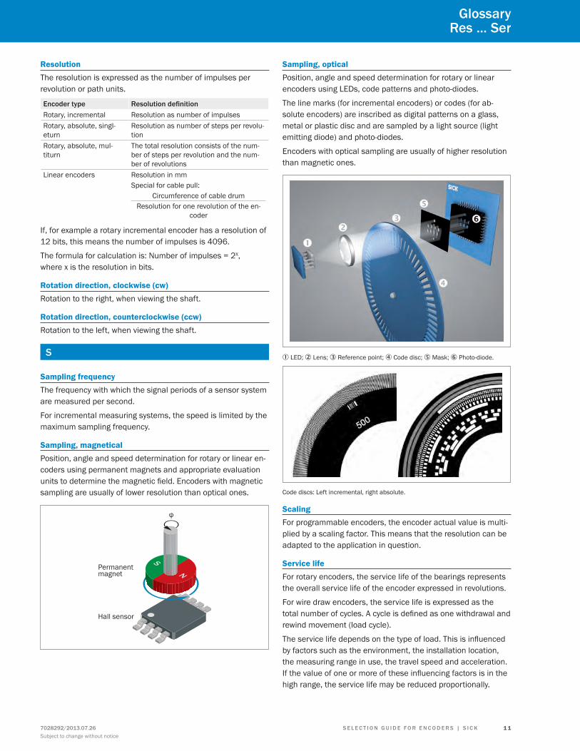
Sampling, opticalPosition, angle and speed determination for rotary or linear encoders using LEDs, code patterns and photo-diodes.
The line marks (for incremental encoders) or codes (for ab-solute encoders) are inscribed as digital patterns on a glass, metal or plastic disc and are sampled by a light source (light emitting diode) and photo-diodes.
Encoders with optical sampling are usually of higher resolution than magnetic ones.
1 LED; 2 Lens; 3 Reference point; 4 Code disc; 5 Mask; 6 Photo-diode.
Code discs: Left incremental, right absolute.
ScalingFor programmable encoders, the encoder actual value is multi-plied by a scaling factor. This means that the resolution can be adapted to the application in question.
Service lifeFor rotary encoders, the service life of the bearings represents the overall service life of the encoder expressed in revolutions.
For wire draw encoders, the service life is expressed as the total number of cycles. A cycle is defined as one withdrawal and rewind movement (load cycle).
The service life depends on the type of load. This is influenced by factors such as the environment, the installation location, the measuring range in use, the travel speed and acceleration. If the value of one or more of these influencing factors is in the high range, the service life may be reduced proportionally.
Glossaryres ... Ser
S E L E C T I O N G u I D E f O r E N C O D E r S | S I C K7028292/2013.07.26Subject to change without notice
1 1
ShaftThe component of a rotary encoder that transfers the rotation movement and torque from the application to the sensor unit of the encoder.
Shaft couplingA shaft coupling is for the indirect connection of two shafts to balance radial, axial or angular offset.
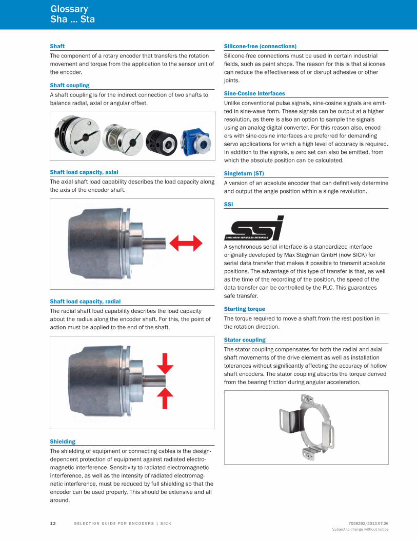
Shaft load capacity, axialThe axial shaft load capability describes the load capacity along the axis of the encoder shaft.
Shaft load capacity, radialThe radial shaft load capability describes the load capacity about the radius along the encoder shaft. For this, the point of action must be applied to the end of the shaft.
ShieldingThe shielding of equipment or connecting cables is the design-dependent protection of equipment against radiated electro-magnetic interference. Sensitivity to radiated electromagnetic interference, as well as the intensity of radiated electromag-netic interference, must be reduced by full shielding so that the encoder can be used properly. This should be extensive and all around.
Silicone-free (connections)Silicone-free connections must be used in certain industrial fields, such as paint shops. The reason for this is that silicones can reduce the effectiveness of or disrupt adhesive or other joints.
Sine-Cosine interfacesUnlike conventional pulse signals, sine-cosine signals are emit-ted in sine-wave form. These signals can be output at a higher resolution, as there is also an option to sample the signals using an analog-digital converter. For this reason also, encod-ers with sine-cosine interfaces are preferred for demanding servo applications for which a high level of accuracy is required. In addition to the signals, a zero set can also be emitted, from which the absolute position can be calculated.
Singleturn (ST)A version of an absolute encoder that can definitively determine and output the angle position within a single revolution.
SSI
A synchronous serial interface is a standardized interface originally developed by Max Stegman GmbH (now SICK) for serial data transfer that makes it possible to transmit absolute positions. The advantage of this type of transfer is that, as well as the time of the recording of the position, the speed of the data transfer can be controlled by the PLC. This guarantees safe transfer.
Starting torqueThe torque required to move a shaft from the rest position in the rotation direction.
Stator couplingThe stator coupling compensates for both the radial and axial shaft movements of the drive element as well as installation tolerances without significantly affecting the accuracy of hollow shaft encoders. The stator coupling absorbs the torque derived from the bearing friction during angular acceleration.
GlossarySha ... Sta
7028292/2013.07.26Subject to change without notice
1 2 S E L E C T I O N G u I D E f O r E N C O D E r S | S I C K
Surrounding field strengthThe surrounding field strength describes the maximum per-mitted influence of external magnetic fields. These external influences must be within the permitted limits to guarantee interference-free functioning of magnetic (linear) encoders.
T
Thermal expansion coefficientThis describes the behavior of a material in relation to changes of its dimensions as influenced by changes in temperature.
TTL RS-422In a transistor-transistor logic (TTL), both the logical status and the amplification are done by transistors, hence the name.
The TTL output is supplied with either a fixed 5 V voltage or a variable voltage of between 10 and 32 V. For this the low range is defined as the ≤ 0.4 V and the high range as ≥ 2.4 V.
W
Wire draw encoderWire draw encoders are position sensors that function according to the cable extension principle. The sensor system consists of a wire draw mechanism and a rotary encoder. The core component of a wire draw encoder is a drum around which a wire is wound in a single layer. Winding is achieved by means of a spring. The resolution of the wire draw encoder can be determined from the relationship between the circumference of the drum and the resolution of the rotary encoder.
Adapter
Encodersystem
Clutch
Measurementdrum
Measuringwire
Springdrive
Z
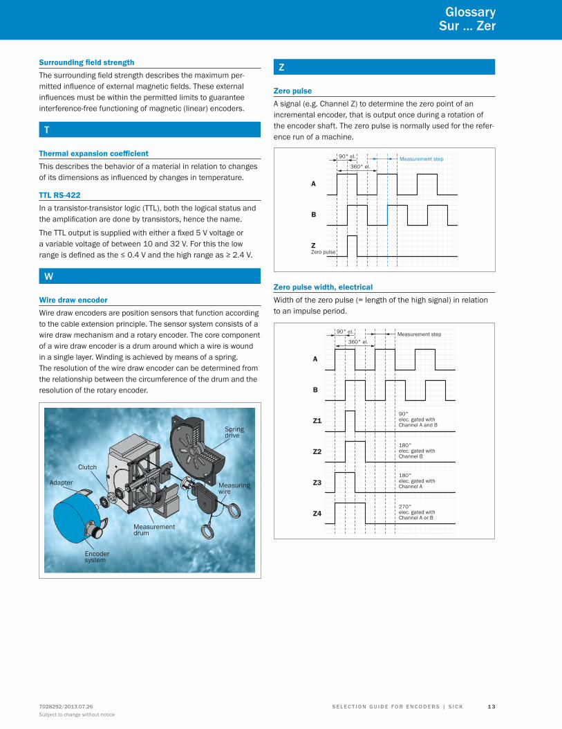
Zero pulseA signal (e.g. Channel Z) to determine the zero point of an incremental encoder, that is output once during a rotation of the encoder shaft. The zero pulse is normally used for the refer-ence run of a machine.
Measurement step
A
B
Z
90° el.
360° el.
Zero pulse
Zero pulse width, electricalWidth of the zero pulse (= length of the high signal) in relation to an impulse period.
A
B
Z1
Z2
Z3
Z4
90°elec. gated withChannel A and B
180°elec. gated withChannel B
180°elec. gated withChannel A
270°elec. gated withChannel A or B
90° el.
360° el.Measurement step
GlossarySur ... Zer
S E L E C T I O N G u I D E f O r E N C O D E r S | S I C K7028292/2013.07.26Subject to change without notice
1 3
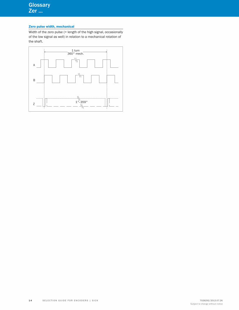
Zero pulse width, mechanicalWidth of the zero pulse (= length of the high signal, occasionally of the low signal as well) in relation to a mechanical rotation of the shaft.
A
B
1°–359°Z
1 turn360° mech.
GlossaryZer ...
7028292/2013.07.26Subject to change without notice
1 4 S E L E C T I O N G u I D E f O r E N C O D E r S | S I C K

Services
for safety and productivity: SICK LifeTime Services SICK LifeTime Services is a comprehensive set of high-quality services provided to support the entire life cycle of prod-ucts and applications from system design all the way to upgrades. These services increase the safety of people, boost the productivity of machines and serve as the basis for our customers’ sustainable business success.
Consulting & DesignGlobally available experts for cost-effective solutions
Training & EducationEmployee qualification for increased competitiveness
Upgrade & RetrofitsUncovers new potential for machines and systems
Verification & OptimizationChecks and recommendations for increased availability
Product & System SupportFast and reliable, by telephone or on location
www.mysick.com – search online and order
ProductApplicationsLiteratureServiceConnection diagramAccessoriesSpare partSoftware
Search online quickly and safely – with the SICK “Finders” Efficiency – with the e-commerce tools from SICK
Product finder: We can help you to quickly target the product that best matches your application.
Applications finder: Select the application description on the basis of the challenge posed, industrial sector, or product group.
Literature finder: Go directly to the operating instructions, technical information, and other literature on all aspects of SICK products.
find out prices and availability: Determine the price and possible delivery date of your desired product simply and quickly at any time.
request or view a quote: You can have a quote gener-ated online here. Every quote is confirmed to you via e-mail.
Order online: You can go through the ordering process in just a few steps.
SICKLifeTimeServices
RETROFIT
T
RA
IN
CONSULT SUP
PO
RT CHECK
Services
S E L E C T I O N G u I D E f O r E N C O D E r S | S I C K7028292/2013.07.26Subject to change without notice
1 5

7028
292/
2013
.07.
26 P
rinte
d in
the
US
S
ubje
ct to
cha
nge
with
out n
otic
e
SICK, Inc. | Minneapolis, MN | United States | www.sickusa.com
Leading technologies
With a staff of more than 5,800 and nearly 50 subsidiaries and represen-tations worldwide, SICK is one of the leading and most successful manufac-turers of sensor technology. The power of innovation and solution competency have made SICK the global market leader. No matter what the project and industry may be, talking with an expert from SICK will provide you with an ideal basis for your plans – there is no need to settle for anything less than the best.
Unique product range
• Non-contact detecting, counting, classifying, positioning and measur-ing of any type of object or media
• Accident and operator protection with sensors, safety software and services
• Automatic identification with bar code and RFID readers
• Laser measurement technology for detecting the volume, position and contour of people and objects
• Complete system solutions for analy-sis and flow measurement of gases and liquids
Comprehensive services
• SICK LifeTime Services – for safety and productivity
• Application centers in Europe, Asia and North America for the develop-ment of system solutions under real-world conditions
• E-Business Partner Portal www.mysick.com – price and availabi-lity of products, requests for quotation and online orders
SICK at a glance
Worldwide presence with subsidiaries in the following countries:
Australia Belgium/Luxembourg Brasil Ceská Republika Canada China Danmark Deutschland España france Great Britain India Israel Italia Japan
México Nederland Norge Österreich Polska românia russia Schweiz Singapore Slovenija South Africa South Korea Suomi Sverige Taiwan Türkiye united Arab Emirates uSA
Please find detailed addresses and additional representatives and agencies in all major industrial nations at www.sick.com