seismic rehabilitation of existing buildings · strategies and approaches for implementing a...
TRANSCRIPT

FEDERAL EMERGENCY MANAGEMENT AGENCY FEMA-1 72 / June 1992
NEHRP Handbook ofTechniques for theSeismic Rehabilitationof Existing Buildings
/
Issued by FEMA in furtherance of theDecade for Natural Disaster Reduction.
m
03
0
0
CD2H
CDC/)-o
CD
CD
C',CD
CD
m
co
-h
cn,
CD
-CO
CD ,
/
I
i

ProgramonImprovedSeismicSafetyProvisions
NEHRP HANDBOOK OF TECHNIQUES
FOR THE SEISMIC REHABILITATION OF
EXISTING BUILDINGS

THE BUILDING SEISMIC SAFETY COUNCIL AND ITS PURPOSE
The Building Seismic Safety Council (BSSC) was established in 1979 under the auspices of the National Instituteof Building Sciences (NIBS) as an entirely new type of instrument for dealing with the complex regulatory,technical, social, and economic issues involved in developing and promulgating building earthquake hazardmitigation regulatory provisions that are national in scope. By bringing together in the BSSC all of the neededexpertise and all relevant public and private interests, it was believed that issues related to the seismic safety ofthe built environment could be resolved and jurisdictional problems overcome through authoritative guidanceand assistance backed by a broad consensus.
The BSSC is an independent, voluntary membership body representing a wide variety of building com-munity interests. Its fundamental purpose is to enhance public safety by providing a national forum that fostersimproved seismic safety provisions for use by the building community in the planning, design, construction,regulation, and utilization of buildings. To fulfill its purpose, the BSSC:
* Promotes the development of seismic safety provisions suitable for use throughout the United States;
* Recommends, encourages, and promotes the adoption of appropriate seismic safety provisions in voluntarystandards and model codes;
* Assesses progress in the implementation of such provisions by federal, state, and local regulatory andconstruction agencies;
* Identifies opportunities for improving seismic safety regulations and practices and encourages public andprivate organizations to effect such improvements;
* Promotes the development of training and educational courses and materials for use by designprofessionals, builders, building regulatory officials, elected officials, industry representatives, othermembers of the building community, and the public;
* Advises government bodies on their programs of research, development, and implementation; and
* Periodically reviews and evaluates research findings, practices, and experience and makes recommenda-tions for incorporation into seismic design practices.
The BSSC's area of interest encompasses all building types, structures, and related facilities and includesexplicit consideration and assessment of the social, technical, administrative, political, legal, and economic impli-cations of its deliberations and recommendations. The BSSC believes that the achievement of its purpose is aconcern shared by all in the public and private sectors; therefore, its activities are structured to provide allinterested entities (i.e., government bodies at all levels, voluntary organizations, business, industry, the designprofession, the construction industry, the research community, and the general public) with the opportunity toparticipate. The BSSC also believes that the regional and local differences in the nature and magnitude of poten-tially hazardous earthquake events require a flexible approach to seismic safety that allows for consideration ofthe relative risk, resources, and capabilities of each community.
The BSSC is committed to continued technical improvement of seismic design provisions, assessment ofadvances in engineering knowledge and design experience, and evaluation of earthquake impacts. It recognizesthat appropriate earthquake hazard reduction measures and initiatives should be adopted by existingorganizations and institutions and incorporated, whenever possible, into their legislation, regulations, practices,rules, codes, relief procedures, and loan requirements so that these measures and initiatives become an integralpart of established activities, not additional burdens. The BSSC itself assumes no standards-making and -promul-gating role; rather, it advocates that code- and standards-formulation organizations consider BSSC recommenda-tions for inclusion into their documents and standards.

BSSC Program on Improved Seismic Safety Provisions
NEHRP HANDBOOK OF TECHNIQUES
FOR THE SEISMIC REHABILITATION OF
EXISTING BUILDINGS
Developed by theBuilding Seismic Safety Council
for theFederal Emergency Management Agency
Based on a Preliminary Version Prepared for FEMA bythe URS/John A. Blume and Associates, Engineers
BUILDING SEISMIC SAFETY COUNCILWashington, D.C.
1992

NOTICE: Any opinions, findings, conclusions, or recommendations expressed in this publication do not
necessarily reflect the views of the Federal Emergency Management Agency. Additionally, neither FEMA nor
any of its employees make any warranty, expressed or implied, nor assume any legal liability or responsibility for
the accuracy, completeness, or usefulness of any information, product, or process included in this publication.
This report was prepared under Contract EMW-88-C-2924 between the Federal Emergency Management Agency
and the National Institute of Building Sciences.
Building Seismic Safety Council reports include the documents listed below-, unless otherwise noted, single copies
are available at no charge from the Council:
AbatementofSeismic Hazards to Lifelines: Proceedings oftheBuilding Seismic Safety Council Workshop on Development of an ActionPlan, 6 volumes, 1987
Action Plan for the Abatement of Seismic Hazards to New and Existing Lifelines, 1987
Guide to Use of the NEHRP Recommended Provisions in Earthquake-Resistant Design of Buildings, 1990
NEHRP (National Earthquake Hazards Reduction Program) Recommended Provisions for the Development of Seismic Regulations
for New Buildings, 1988 and 1991 Editions, 2 volumes and maps, 1988 and 1991
NEHRP Handbook for the Seismic Evaluation of Edsting Buildings, 1992
NEHRP Handbook of Techniques for the Seismic Rehabilitation of Existing Buildings, 1992
Non-Technical Explanation of the NEHRP Recommended Provisions, Revised Edition, 1990
Seismic Considerations for Communities at Risk, 1990'
Seismic Considerations: Elementary and Secondary Schools, Revised Edition, 1990
Seismic Considerations: Health Care Facilities, Revised Edition, 1990
Seismic Considerations: Hotels and Motels, Revised Edition, 1990
Seismic Considerations: Apartment Buildings, 1988
Seismic Considerations: Office Buildings, 1988
Societal Implications: Selected Readings, 1986.
Strategies and Approaches for Implementing a Comprehensive Program to Mitigate the Risk to Lifelines from Earthquakes and Other
Natural Hazards, 1989 (available from the National Institute of Building Sciences for Sil)
For further information concerning any of these documents or the activities of the BSSC, contact the Executive
Director, Building Seismic Safety Council, 1201 L St., N.W., Suite 400, Washington, D.C. 20005.
An earlier version of this publication was entitled Societal Implications: A Community Handbook.
ii

FOREWORD
The Federal Emergency Management Agency (FEMA) is pleased to have sponsored the preparation of thispublication on seismic strengthening of existing buildings. The publication is one of a series that FEMA issponsoring to encourage local decision makers, design professionals, and other interested groups to undertakea program of mitigating the risks posed by existing hazardous buildings in the event of an earthquake.Publications in this series are being prepared under the National Earthquake Hazards Reduction Program(NEHRP) and examine both the engineering/architectural aspects and societal impacts of seismic rehabilitation.
FEMA's existing buildings activities are structured to result in a coherent, cohesive, carefully selected andplanned reinforcing set of documents designed for national applicability. The resulting publications (descriptivereports, handbooks, and supporting documentation) provide guidance primarily to local elected and appointedofficials and design professionals on how to deal not only with earthquake engineering problems but also withthe public policy issues and societal dislocations associated with major seismic events. It is a truly interdisciplin-ary set of documents that includes this handbook of techniques as Well as a companion volume presenting amethodology for conducting an evaluation of the seismic safety of existing buildings.
With respect to this handbook, FEMA gratefully acknowledges the expertise and efforts of the BuildingSeismic Safety Council's Retrofit of Existing Buildings Committee, Board of Direction, member organizations,and staff and of the members of the Technical Advisory Panel and URS/John A. Blume and Associatesmanagement and staff.
Federal Emergency Management Agency
iii

PREFACE
This handbook of techniques for solving a variety of seismic rehabilitation problems and its companionpublication on the seismic evaluation of existing buildings reflect basic input provided by two organizationsrecognized for their retrofit evaluation and design experience as well as the results of a consensus developmentactivity carried out by the Building Seismic Safety Council (BSSC). The preliminary version of this document,the NEHRP Handbook of Techniques for the Seismic Rehabilitation of Existing Buildings, was developed forFEMA by URS/John A. Blume and Associates, Engineers (URS/Blume). A companion volume, the NEHRPHandbook for the Seismic Evaluation of Existing Buildings, for which a preliminary version was developed forFEMA by the Applied Technology Council (ATC), provides a method for evaluating existing buildings to identifythose that are likely to be seismically hazardous. The BSSC project, initiated at the request of FEMA in October1988, has focused on identification and resolution of technical issues in and appropriate revision of the twohandbooks by a 22-member Retrofit of Existing Buildings (REB) Committee composed of individuals possessingexpertise in the various subjects needed to address seismic rehabilitation.
The balloting of the two handbooks was conducted on a chapter-by-chapter basis in September andOctober 1991. Although all parts of both handbooks passed the ballot by the required two-thirds majority, theBoard, after reviewing the ballot results in November 1991, concluded that many of the comments weresufficiently serious to warrant further consideration and that the REB Committee should have the opportunityto review the ballot comments and propose changes for reballoting in response to those considered persuasive.The REB Committee members then were asked to review the ballot comments and forward the results of theirreview to a member of the REB Executive Committee. In turn, the Executive Committee met in early January1992 to consider committee member suggestions and prepare responses to the ballot comments and proposalsfor revision of the handbooks. The Executive Committee recommendations for reballoting were presented toand accepted by the BSSC Board. The reballot proposals were developed and submitted to the BSSC memberorganizations for balloting in late January 1992. All the reballot proposals passed but several issues raised incomments were considered and resolved at a special meeting of the Council in February 1992.
The BSSC REB Committee and Board of Direction believe that these two handbooks will prove to bebeneficial to those who are involved in or who need to begin exploring the seismic evaluation and rehabilitationof existing buildings, a topic of growing importance especially in the eastern and midwestern parts of the nationwhere little such work has been done. It is hoped that experience with the application of these handbooks willgenerate feedback that can serve as the foundation for the enhancement of future documents dealing with theseismic rehabilitation of existing buildings. To this end, a User Comment Form is included in the handbooksto stimulate those who work with the handbooks to report their experiences. In addition, since some of theissues raised by BSSC member organizations during the balloting of the handbooks bear on the need for futureenhancement of the information presented, a summary of the results of the BSSC balloting including allcomments received and committee decisions/responses to those comments is available to interested readers uponrequest to the BSSC.
The Board wishes to emphasize that these documents are intended to serve as informational "points ofdeparture" for the professional involved in seismic evaluation and rehabilitation. They cannot yet be consideredall inclusive nor are they intended to serve as the basis for regulation. Rather, it is hoped that both will proveto be of sufficient value to warrant expansion and refinement.
Considerable effort has gone into the development of this handbook. On behalf of the BSSC Board, Iwish to acknowledge the organizations and individuals who have participated. The Board is particularly gratefulfor the extensive contribution of time and expertise from those serving on its Retrofit of Existing BuildingsCommittee of volunteer experts:
Daniel Shapiro, SOH and Associates, San Francisco, California (Committee Chairman)M. Agbabian, University of Southern California, Los Angeles, CaliforniaChristopher Arnold, Building Systems Development, San Mateo, CaliforniaMohammad Ayub, U.S. Departmene of Labor, Washington, D.C.John R. Battles, Southern Building Code Congress, International, Birmingham, Alabama
v

Pamalee Brady, U.S. Army Construction Engineering, Champaign, IllinoisVincent R. Bush, Consulting Structural Engineer, Walnut, CaliforniaJohn Canestro, City of Orinda, Pleasanton, CaliforniaArnaldo T. Derecho, Wiss, Janney, Elstner Associates, Incorporated, Northbrook, IllinoisEdward Diekmann, GFDS Structural Engineers, San Francisco, CaliforniaRonald P. Gallagher, R. P. Gallagher Associates, Incorporated, San Francisco, CaliforniaJames R. Harris, J. R. Harris and Company, Denver, ColoradoJohn Kariotis, Kariotis and Associates, South Pasadena, CaliforniaFranklin Lew, Contra Costa County, Martinez, CaliforniaFrank E. McClure, Consulting Structural Engineer, Orinda, CaliforniaAllan R. Porush, Dames and Moore, Los Angeles, CaliforniaNorton S. Remmer, Consulting Engineer, Worcester, MassachusettsRalph Rowland, Architectural Research, Cheshire, ConnecticutEarl Schwartz, Los Angeles City Department of Building and Safety, Los Angeles, CaliforniaWilliam W. Stewart, William Stewart and Associates, Clayton, MissouriRobert Voelz, Bentley Engineering Company, San Francisco, CaliforniaLoring A. Wyllie, H. J. Degenkolb Associates, San Francisco, California
Needless to say, the Council's project would not have been successful without the developmental work andcooperation of the URS/Blume project staff: R. Martin Czarnecki, Principal-in-Charge; John F. Silva, ProjectManager; David M. Bergman, Project Engineer; Joseph P. Nicoletti, Consultant; Walter N. Mestrovich; and KitWong.
Further, the BSSC Board wishes to acknowledge the contribution of URS/Blume's Technical Advisory Panel:Vitelmo V. Bertero, Robert D. Hanson, James 0 Jirsa, James M. Kelley, Stephen A. Mahin, Roger E. Scholl,and James K. Wight.
Finally, I would be remiss if I did not acknowledge the effort of the BSSC staff: James R. Smith, ExecutiveDirector; 0. Allen Israelsen, Professional Engineer and Project Manager; Claret M. Heider, Technical Writer-Editor; and Karen E, Smith, Administrative Assistant.
Gerald JonesChairman, BSSC Board of Direction
vi
*Corresponding member.

USER COMMENT FORMPlease fill out and return this form to the BSSC at 1201 L Street, N.W., 4 th Hor, Washington, D.C. 20005.Your cooperation is greatly appreciated.
1. Describe your experience in using this handbook.
What type of building was evaluated and proposed for rehabilitation?
How was the evaluation performed? Was the NEHRP Handbook for the Seismic Evaluation of ExistingBuildings used?
Which techniques in this handbook were considered? What technique was selected? Was therehabilitation completed?
Were problems encountered in using this handbook? If so, describe the problems and how they weresolved.
2. Prior to your use of this handbook, were you familiar with the NEHRP Recommended Provisions for theDevelopment of Seismic Regulations for New Buildings.
3. Do you have recommendations for improving this handbook.
Name Title
Organization
Address
Telephone and FAX Numbers
vii

CONTENTS
FOREWORD iii
PREFACE v
USER COMMENT FORM vii
GLOSSARY xv
1. INTRODUCTION 1
1.1 Background 11.2 Development of This Handbook 21.3 Purpose of This Handbook 21.4 Scope and Limitations 31.5 Organization of This Handbook 3
2. SEISMIC VULNERABILITY OF BUILDINGS S
2.0 Introduction 52.1 General Attributes of Structures 5
2.1.1 Strength 52.1.2 Stiffness 52.1.3 Ductility 62.1.4 Damping 6
2.2 Adverse Design and Construction Features 62.2.1 Lack of Direct Load Path 62.2.2 Irregularities 72.2.3 Lack of Redundancy 13.2.2.4 Lack of Toughness 132.2.5 Adjacent Buildings 14
23 Deteriorated Condition of Structural Materials 14
3. SEISMIC STRENGTHENING OF EXISTING BUILDINGS 17
3.0 Introduction 173.0.1 Cost Considerations 173.0.2 Functional Considerations 173.0.3 Aesthetic Considerations 183.0.4 Seismic Zonation 18
3.1 Vertical-resisting Elements--Moment Resisting Systems 183.1.1 Steel Moment Frames 183.1.2 Concrete Moment Frames 223.1.3 Moment Frames with Infil&s 263.1.4 Precast Concrete Moment Frames 28
3.2 Vertical-resisting Elements--Shear Walls 283.2.1 Reinforced Concrete or Reinforced Masonry Shear Walls 283.2.2 Precast Concrete Shear Walls 343.2.3 Unreinforced Masonry Shear Walls 343.2.4 Shear Walls in Wood Frame Buildings 37
ix

3.3 Vertical-resisting Elements--Braced Frames 383.3.1 Steel Concentric Braced Frames 383.3.2 Rod or Other Tension Bracing 413.3.3 Eccentric Bracing 42
3.4 Vertical-resisting Elements--Adding Supplemental Members 433.4.1 Relative Compatibility 443.4.2 Exterior Supplemental Elements 453.4.3 Interior Supplemental Elements 45
3.5 Diaphragms 46
3.5.1 Timber Diaphragms 473.5.2 Concrete Diaphragms 513.5.3 Poured Gypsum Diaphragms 563.5.4 Precast Concrete Diaphragms 563.5.5 Steel Deck Diaphragms 593.5.6 Horizontal Steel Bracing 64
3.6 Foundations 65
3.6.1 Continuous or Strip Wall Footings 663.6.2 Individual Pier or Column Footings 683.6.3 Piles or Drilled Piers 70
3.6.4 Mat Foundations 723.7 Diaphragm to Vertical Element Connections 72
3.7.1 Connections of Timber Diaphragms 723.7.2 Connections of Concrete Diaphragms 843.7.3 Connections of Poured Gypsum Diaphragms 863.7.4 Connections of Precast Concrete Diaphragms 863.7.5 Connections of Steel Deck Diaphragms Without Concrete Fill 873.7.6 Connections of Steel Deck Diaphragms with Concrete Fill 893.7.7 Connections of Horizontal Steel Bracing 90
3.8 Vertical Element to Foundation Connections 913.8.1 Connections of Wood Stud Shear Walls 913.8.2 Connections of Metal Stud Shear Walls 95
3.8.3 Connections of Precast Concrete Shear Walls 953.8.4 Connections of Braced Frames 973.8.5 Connections of Steel Moment Frames 98
3.9 Adding a New Supplemental System 983.9.1 Supplemental Braced Frame System 993.9.2 New Shear Wall System 993.9.3 Structural Additions 101
4. DECREASING DEMAND ON EXISTING SYSTEMS 103
4.0 Introduction 103
4.1 Reducing the Weight of the Building 1034.2 Increasing the Fundamental Period and the Energy Dissipating Capacity
of the Structural System 1044.3 Alternate Procedures 105
4.3.1 Seismic Isolation 105
4.3.2 Supplemental Damping 105
5. REHABILITATION OF NONSTRUCTURAL ARCHITECTURAL COMPONENTS 107
5.0 Introduction 107
5.1 Exterior Curtain Walls 1075.2 Appendages 108
5.3 Veneers 109
x

5.4 Partitions 1095.5 Ceilings 1135.6 Lighting Fixtures 1135.7 Glass Doors and Windows 1145.8 Raised Computer Access Floors 115
6. REHABILITATION OF NONSTRUCTURAL MECHANICAL AND ELECTRICAL COMPONENTS 117
6.0 Introduction 117
6,1 Mechanicai and Electrical Equipment 117t Ductwork and Piping 1266.3 Elevators 133
6.4 Emergency Power Systems 1336.5 Hazardous Material Storage Systems 1356.6 Communication Systems 1376.7 Computer Equipment 137
BIBLIOGRAPHY 143
APPENDICES
149165185
A Seismic-Force-Resisting Elements in BuildingsB Summary of Strengthening TechniquesC Rehabilitation Examples
MINORITY OPINION
BSSC BOARD OF DIRECTION AND MEMBER ORGANIZATIONS
FIGURES
LE(iFNf) FOR FIGURES: (E) = Existing, (L) = Left, (N) = New. (R) - Right
2.2.2.1 Vertical irregularities--examples of in-plane and out-of-plane discontinuities2.2.2.4a Horizontal and plan irregularities--rehabilitating a structure to reduce torsional loads2.2.2.4b Horizontal and plan irregularities--examples of rehabilitating buildings with re-entrant corners2.2.2.4c Horizontal and plan irregularities--example of strengthening a split level diaphragm2.2.2.4d Horizontal and plan irregularities--example of rehabilitating building with nonparallel systems
3.1.1.2a Modification of an existing simple beam to a moment connection3.1.1.2b Strengthening an existing column3.1.1.2c Strengthening an existing beam3.1.2.2a Encasing an existing beam in concrete3.1.2.2b Strengthening an existing concrete column3.1.2.2c Strengthening an existing concrete frame building with a reinforced concrete shear wall3.2.1.2a Strengthening an existing shear wall by filling in existing openings3.2.1.2b Example of details for enclosing. an existing opening in a reinforced concrete or masonry wall3.2.1.2c Strengthening an existing reinforced concrete or masonry wall3.2.1.4 Example of strengthening an existing coupling beam at an exterior wall3.2.3.2 Example of center coring technique3.3 Bracing types3.3.1.2 Addition to or replacement of an existing X-brace3.4 Examples of supplementary strengthening3.4.2 Example of supplemental in-plane strengthening by the addition of an external buttress3.4.3 Connection of a supplemental interior shear wall
0 : ~~~~~~~~~~~xi
193
195
81011
1212
19
2021
2324-25
262930,31
3235
3839
444546

3.5.1.3 Exterior sheathing and top plate chord in a wood frame building 493.5.1.4a Reinforcement of an opening in an existing timber diaphragm 503.5.1.4b New drag strut in an existing wood diaphragm 513.5.2.2 Strengthening an existing concrete diaphragm with a new topping slab and chord 523.5.2.3 Adding a new chord member to an existing concrete diaphragm (not recommended
for precast elements) 533.5.2.4a Reinforcement of an opening in an existing concrete diaphragm 543.5.2.4b Strengthening openings in overlaid diaphragms 553.5.4.2 Strengthening an existing precast concrete diaphragm with a concrete overlay 573.5.4.3 Adding a new steel member to an existing precast concrete diaphragm 583.5.5.2a Strengthening an existing steel deck diaphragm 603.5.5.2b Strengthening an existing steel deck diaphragm 613.5.5.2c Strengthening an existing building with steel decking and concrete or masonry walls 623.5.5.2d Strengthening an existing building with steel decking and concrete or masonry walls 633.6.1.2a Underpinning an existing footing 663.6.1.2b Strengthening an existing wall footing by the addition of drilled piers 673.6.2.3 Upgrading an existing pile foundation 713.7.1.2a Strengthening the connection of a diaphragm to an interior shear wall
(wall parallel to floor joist) 733.7.1.2b Strengthening the connection of a diaphragm to an interior shear wall
(wall perpendicular to floor joist) 743.7.1.3 Strengthening an existing wood stud shear wall with a large opening 763.7.1.4a Strengthening out-of-plane connections of a wood diaphragm 773.7.1.4b Strengthening out-of-plane connections of a wood diaphragm 783.7.1.4c Strengthening out-of-plane connections of a wood diaphragm 793.7.1.4d Strengthening out-of-plane connections of a wood diaphragm 803.7.1.4e Strengthening tensile capacity of an existing glulam beam connection 803.7.1.5a Strengthening the connection between shear walls using a metal strap 813.7.1.5b Strengthening the connection between shear walls using a hold-down 823.7.1.5c Strengthening shear wall uplift capacity at a discontinuity 833.7.2.2 Use of a collector member to improve shear transfer from a concrete diaphragm 853.7.5.2 Strengthening the connection of steel deck diaphragm to a concrete or masonry wall 883.8.1.2a Providing wall to foundation anchors 923.8.1.2b Alternate detail for providing wall to foundation anchors 933.8.1.3 Strengthening a cripple stud wall 943.8.1.4 Strengthening the uplift capacity of a wall to foundation connection 953.8.3.2 Strengthening a precast concrete wall to foundation connection 963.9.1 Strengthening using a supplemental braced frame system 993.9.2 Strengthening by providing a new shear wall system 1003.9.3 Strengthening with a new building addition 101
5.1a Flexible connection for precast concrete cladding 1075.1b Detail for flexible connection for precast concrete cladding 1085.2a Strengthening a masonry parapet with a new concrete overlay 1095.2b Strengthening a masonry parapet with steel braces 1095.4a Bracing an interior masonry partition 1115.4b Bracing an interior masonry partition 1125.5 Lateral bracing of a suspended ceiling 1135.6 Providing safety wires for suspended lighting fixtures 1145.8a Access floor pedestals 1155.8b Strengthening of access floor pedestals 116
xii

6.1a Typical detail of equipment anchorage 118
6.lb Alternate details for anchoring equipment 119-120
6.1c Prefabricated vibration isolation assembly with lateral seismic stops 121
6.1d Seismic restraints added to existing equipment with vibration isolation 122
6.1e Multidirectional seismic restraint 123
6.1f Typical bracing for suspended equipment 124
6.lg Strapping of domestic water heater 125
6.2a Lateral and longitudinal braces for large diameter ducting 127
6.2b Lateral and longitudinal braces for small diameter ducting 128
6 2c Lateral and longitudinal braces for rectangular ducting 129
6.2d Lateral braces for piping 130
6.2e Longitudinal pipe brace 131
6.2f Lateral brace for multiple pipes 132
6.2g Longitudinal brace for multiple pipes 132
6.4a Bracing of existing battery racks 133
6.4b Bracing of horizontal tank 134
6.5a Protective measures for hazardous materials 135
6.5b Anchorage detail for pressurized tanks 136
6.7a Rigid anchorage of computer equipment 138
6.7b Flexible anchorage of computer equipment 139
6.7c Tether and opening guards for protection of computer equipment 140
6.7d Strapping of electronic data processing units 141
xdii

GLOSSARY
BOUNDARY ELEMENT: An element at the edge of an opening or at the perimeter of a shear wall ordiaphragm.
BRACED FRAME: An essentially vertical truss, or its equivalent, of the concentric or eccentric type that isprovided in a building frame or dual system to resist lateral forces.
CHEVRON BRACING: Bracing where a pair of braces, located either both above or both below a beam,terminates at a single point within the clear beam span.
CHORD: See DIAPHRAGM CHORD.
COLLECTOR: A member or element provided to transfer lateral forces from a portion of a structure to verticalelements of the lateral-force-resisting system (also called a drag strut).
CONCENTRICALLY BRACED FRAME (CBF): A braced frame in which the members are subjected primarilyto axial forces.
CONTINUITY TIES: Structural members and connections that provide a load path between diaphragm chordsto distribute out-of-plane wall loads.
COUPLING BEAM: A structural element connecting adjacent shear walls.
DAMPING: The internal energy absorption characteristic of a structural system that acts to attenuate inducedfree vibration.
DEMAND: The prescribed design forces required to be resisted by a structural element, subsystem, or system.
DIAPHRAGM: A horizontal, or nearly horizontal, system designed to transmit lateral forces to the verticalelements of the lateral-force-resisting system. The term "diaphragm" includes horizontal bracing systems.
DIAPHRAGM CHORD: The boundary element of a diaphragm or shear wall that is assumed to take axialtension or compression.
DIAPHRAGM STRUT: The element of a diaphragm parallel to the applied load that collects and transfersdiaphragm shear to vertical-resisting elements or distributes loads within the diaphragm. Such members maytake axial tension or compression. Also refers to drag strut, tie, collector.
DRAG STRUT: See COLLECTOR.
DRIFT: See STORY DRIFT.
DUCTILITY: The ability of a structure or element to dissipate energy inelastically when displaced beyond itselastic limit without a significant loss in load carrying capacity.
ECCENTRICALLY BRACED FRAME (EBF): A diagonal braced frame in which at least one end of each braceframes into a beam a short distance from a beam-column joint or from another diagonal brace.
FUNDAMENTAL PERIOD OF VIBRATION: The time it takes the predominant mode of a structure to moveback and forth when vibrating freely.
xv

HOLD-DOWN: A prefabricated steel element consisting of a tension rod, end brackets and bolts or lags usedto transfer tension across wood connections.
HORIZONTAL BRACING SYSTEM: A horizontal truss system that serves the same function as a diaphragm.
K-BRACING: Bracing where a pair of braces located on one side of a column terminates at a single point withinthe clear column height.
LATERAL-FORCE-RESISTING SYSTEM: That part of the structural system assigned to resist lateral forces.
LINK BEAM: That part or segment of a beam in an eccentrically braced frame that is designed to yield in shearand/or bending so that buckling or tension failure of the diagonal brace is prevented.
MOMENT RESISTING SPACE FRAME: A structural system with an essentially complete space frameproviding support for vertical loads.
REDUNDANCY: A measure of the number of alternate load paths that exist for primary structural elementsand/or connections such that if one element or connection fails, the capacity of alternate elements or connectionsare available to satisfactorily resist the demand loads.
RE-ENTRANT CORNER: A corner on the exterior of a building that is directed inward such as the insidecorner of an L-shaped building.
SHEAR WALL: A wall, bearing or nonbearing, designed to resist lateral forces acting in the plane of the wall.
SHOTCRETE: Concrete that is pneumatically placed on vertical or near vertical surfaces typically with aminimum use of forms.
SOFT STORY: A story in which the lateral stiffness is less than 70 percent of the stiffness of the story above.
SOIL-STRUCTURE RESONANCE: The coincidence of the natural period of a structure with a dominantfrequency in the ground motion.
STORY DRIFT: The displacement of one level relative to the level above or below.
STRUCTURE: An assemblage of framing members designed to support gravity loads and resist lateral forces.Structures may be categorized as building structures or nonbuilding structures.
SUBSYSTEMS: One of the following three principle lateral-force-resisting systems in a building: vertical-resisting elements, diaphragms, and foundations.
SUPPLEMENTAL ELEMENT: A new member added to an existing lateral-force-resisting subsystem that sharesin resisting lateral loads with existing members of that subsystem.
V-BRACING: Chevron bracing that intersects a beam from above. Inverted V-bracing is that form of chevronbracing that intersects a beam from below.
VERTICAL-RESISTING ELEMENTS: That part of the structural system located in a vertical or near verticalplane that resists lateral loads (typically a moment frame, shear wall, or braced frame).
WEAK STORY: A story in which the lateral strength is less than 80 percent of that in the story above.
X-BRACING: Bracing where a pair of diagonal braces crosses near mid-length of the bracing members.
xvi

1
INTRODUCMION
The risks posed by buildings not designed for earthquake loads or by nonengineered buildings have beenrecognized for nearly a century. Advances in earthquake-related science and technology during the past fewdecades have led to a realization that earthquakes and the resulting risk to life are a national problem. Indeed,damaging earthquakes in the eastern United States, although occurring less frequently than in California, maypose an equal, if not greater, threat to the national economy and social fabric.
The benefits of applying earthquake-resistant design to reduce the hazards of new buildings wereacknowledged in California following the 1906 San Francisco earthquake but appropriate design practices werenot implemented to any degree until after the disastrous 1933 earthquake in Long Beach, California. Today,earthquake-resistant design in new construction is accepted practice in California but has been only recentlyachieved a significant degree of acceptance in other parts of the United States. Thus, a very large number ofexisting buildings in the country can be presumed to have inadequate earthquake resistance and to pose a seriousrisk.
Detailed post-earthquake investigations of building failures have provided engineers with considerableinformation concerning the details of building design and construction that enhance earthquake resistance. The1971 earthquake in San Fernando, California, was particularly revealing in this regard and engendered a newwave of concern for seismic rehabilitation of existing buildings. Notable among the earthquake rehabilitationprojects begun in the 1970s was the systematic seismic vulnerability evaluation, and strengthening as needed, ofall Veterans Administration (VA) hospitals in the United States. Concurrently, other federal agencies such asthe Department of Defense (DOD) and the General Services Administration (GSA) initiated programs toidentify and mitigate seismic hazards in public buildings under their authority. These and similar projects havegenerated a substantial body of knowledge regarding earthquake rehabilitation of buildings. The Loma Prietaearthquake seems to have added impetus to seismic rehabilitation in the private sector. (Note that the greatestexperience in seismic rehabilitation has been gained in high seismic zones; see Sec. 3.0.4 for guidance concerningthe application of seismic rehabilitation techniques in areas of lower seismicity.)
1.1 BACKGROUND
One of the objectives of the Earthquake Hazards Reduction Act of 1977 (P.L. 95-124 as amended) is . . . thedevelopment of methods for . . . rehabilitation and utilization of man-made works so as to effectively resist thehazards imposed by earthquakes... ." The National Earthquake Hazards Reduction Program submitted to theCongress by the President on June 22, 1978, stresses that absent a reliable capability to predict earthquakes, "itis important that hazards be reduced from those (substandard) structures presenting the greatest risks in termsof occupancy and potential secondary impact."
In Fiscal Year 1984, FEMA started an extensive program to encourage the reduction of seismic hazardsposed by existing buildings throughout the country. The first project in the program was the formulation of acomprehensive 5-year plan on what needed to be done and what the required resources would be. The plan wascompleted in Fiscal Year 1985. As resources have become available since that time, FEMA has used this planas a basis for developing a multi-volume, self-reinforcing, cohesive, coherent set of nationally applicablepublications on engineering measures and societal problems related to the seismic rehabilitation of existingbuildings. These publications include reports presenting a method for rapid visual screening of buildings, anengineering methodology for a seismic safety evaluation of different types of buildings that is a companion tothis document, seismic strengthening techniques for various types of buildings (this handbook), typical costs ofseismic rehabilitation of existing buildings, an approach to establishing programs and priorities for seismicrehabilitation of existing buildings, potential financial incentives for establishing such programs and instructions
1
on the conduct of workshops to encourage local initiatives in this field and conclusions from a number of applica-tions workshops held in various states, and a model to derive direct economic costs and benefits to owners andoccupants of buildings in the private sector. Further, the preparation of a comprehensive set of guidelines forseismic rehabilitation (with commentary) has been initiated.
1.2 DEVELOPMENT OF THIS HANDBOOK
Recognizing that a large number of techniques currently are being utilized to mitigate seismic hazards in existingvulnerable buildings, the FEMA contracted with URS/John A. Blume and Associates, Engineers, (referred toherein as URS/Blume) in 1987 to identify and describe generally accepted rehabilitation techniques. ThisURS/Blume effort resulted in the preliminary version of this handbook published by FEMA in March 1989.It was based primarily on a review of existing literature and input from a panel of project consultants. Theprimary source documents and sources reviewed included The Abstract Joumal of Earthquake Engineering, theEarthquake Engineering Research Center Library at the University of California at Berkeley, the proceedingsof the World, U.S. National, and European Conferences on Earthquake Engineering, the U.S./Japan Seminarson Repair and Retrofit of Structures, the Dialogue Compendex, and the National Technical Information Service(NTIS).
The Building Seismic Safety Council (BSSC) project, initiated at the request of FEMA in October 1988, wasstructured to focus on identification and resolution of technical issues in the preliminary version of the handbook(as well as in a companion publication presenting a methodology for conducting an evaluation of the seismicsafety of existing buildings) and appropriate revision by a 22-member Retrofit of Existing Buildings (REB)Committee composed of individuals possessing expertise in the various subjects needed to address seismicrehabilitation. Conduct of the BSSC project is discussed in the Preface (see page v).
1.3 PURPOSE OF THIS HANDBOOK
There is a variety of approaches to seismic rehabilitation, each with specific merits and limitations. Therehabilitation technique most appropriate for use with a particular building will depend on the uniquecharacteristics of the building. Thus, this handbook is to provide those interested or involved in seismicrehabilitation with:
c A general understanding of the common deficiencies in the structural and nonstructural components ofexisting buildings that cause seismic performance problems,
* Descriptions of some of the techniques that might be used to correct deficiencies for various constructiontypes, and
* Information on the relative merits of alternative techniques.
In short, this handbook is intended to stimulate understanding such that, when assessing the rehabilitationalternatives available, building owners and design professionals can make an informed decision concerning thebest solution for a specific building, location, and occupancy.
This handbook is designed to be compatible with the NEHRP Handbook for the Seismic Evaluation ofExisting Building (referred to herein as the NEHRP Evaluation Handbook), which provides a standardmethodology for evaluating buildings of different types and occupancies in areas of different seismicity throughoutthe United States. Seismic deficiencies of buildings identified using the NEHRP Evaluation Handbookmethodology can be further analyzed to determine the seismic resistance. The deficiencies identified then canbe mitigated using accepted rehabilitation techniques described in this handbook or other sources ofrehabilitation information.
2

1.4 SCOPE AND LIMITATIONS
The rehabilitation techniques identified and described in this handbook are intended to be consistent with therequirements for new construction prescribed in the 1988 Edition of the NEHRP Recommended Provisions forthe Development of Seismic Regulations for New Buildings (FEMA Publications 95, 96, and maps). The intentof the rehabilitation is to provide life safety but not necessarily to upgrade the structure to meet modernstandards of life safety and property protection.
Given the great number of potential seismic strength problems and, solutions, it is not now possible toprepare a compendium of all available techniques for all existing building types in all areas of the nation at riskfrom earthquakes. In recognition of the broad variation in the details of design and construction used over theyears, the design professional will need to consider a wide array of possible techniques for rehabilitation, andthis handbook is intended to serve as an informational "point of departure."
This handbook is organized to permit a component-by-component consideration of deficiencies andrehabilitation techniques. The reader, however, is cautioned against selecting specific rehabilitation techniqueswithout first identifying the overall deficiencies of the building and determining whether deficiencies are due toa combination of component deficiencies, inherent adverse design and construction features, or a weak link.
Furthermore, a building's design and construction characteristics as well as the condition of materials of itsconstruction 'affect seismic performance. Therefore, in order to make an informed decision concerningappropriate cost-effective techniques for seismic strengthening of an existing building, the engineer mustunderstand the structural system or combination of systems that resist the lateral loads; the advantages anddisadvantages associated with the physical attributes of the systems; and any constraints on the optimumperformance of the system due to adverse design or construction features or deteriorated materials.
It is hoped that experience with the application of this handbook and its companion document will generatefeedback that can serve as the foundation for the enhancement of future documents dealing with seismicrehabilitation.
1.5 ORGANIZATION OF THIS HANDBOOK
Chapter 2 describes the physical attributes that affect the seismic performance of all structures. The generalcharacteristics of all structural materials and- systems (i.e., strength, stiffness, ductility, and damping) areaddressed as are design and construction features that may impair a building's seismic performance. Techniquesfor strengthening vertical elements, diaphragms, foundations, and connections are addressed in Chapter 3.Techniques for decreasing the demand on existing structures are addressed in Chapter 4. Chapters 5 and 6present techniques to mitigate damage to nonstructural architectural and mechanical and electrical components,respectively. Appendices include a listing of the seismic-force-resisting elements commonly found in 15 commonbuilding types, a matrix summary of rehabilitation techniques, and examples of rehabilitation.
As indicated above, this handbook is structured to be used with the NEHRP Evaluation Handbook. Bothof these handbooks are organized to address the following building systems and components: vertical elementsresisting horizontal loads (i.e., moment-resisting frames, shear walls, and braced frames); horizontal elementsresisting lateral loads (i.e., diaphragms); foundations; and connections between subsystems. Table 1.5 shows therelationship between the handbooks.
The American Iron and Steel Institute has written a minority opinion concerning this statement; see page193.
3

TABLE 1i5Correlation of Contents Between the Evaluation and Techniques Handbooks
4
NEHRP Handbook of Techniques for the Seismic Rehabilitation NEHRP Handbook for the Seismic Evaluation ofof Existing Buildings Ewisng Buildngs
Chapter 2, Seismic Vulnerability of Buildings Chapter 3, Building SystemsSection 3.9, Adding a New Supplemental SystemChapter 4, Decreasing Demand on Existing System
Section 3.1, Moment Resisting Systems Chapter 4, Moment Resisting Systems
Section 3.2, Shear Walls Chapter 5, Shear Walls
Section 3.3, Braced Frames Chapter 6, Braced Frames
Section 3.5, Diaphragms Chapter 7, Diaphragms
Section 3.7, Diaphragm to Vertical Element Connections Chapter 8, Connections.Section 3.8, Vertical Element to Foundation Connections
Section 3.6, Foundations Chapter 9, Foundations and Geologic Site Hazards
Chapter 5, Rehabilitation of Nonstructural Architectural Com- Chapter 10, Elements Not a Part of theponents Lateral-Force-Resisting SystemChapter 6, Rehabilitation of NonstructuralMechanical and Electrical Components

2
SEISMIC VULNERABILITY OF BUILDINGS
2.0 INTRODUCTION
This chapter describes the general characteristics of all structural materials and systems (i.e., strength, stiffness,ductility, and damping) and the design and construction features that may adversely affect the seismicperformance of a structure. Since an informed decision regarding the most cost-effective techniques forrehabilitating an existing structure to resist seismic forces requires an understanding of the structural system orcombination of systems that resist the lateral loads, the advantages or disadvantages associated with the physicalattributes of the systems and the constraints on system performance due to adverse design or constructionfeatures, the emphasis here is on the complete structural system. Chapter 3 focuses on techniques to strengthenthe three principal lateral-force-resisting subsystems (vertical-resisting elements, diaphragms, and foundations)and the connections between these subsystems. Chapter 4 identifies methods to rehabilitate structures byreducing demand.
2.1 GENERAL AYIRIBUTES OF STRUCTURES
Strength, stiffness, ductility, and damping govern the dynamic response of a structure to ground motion. An idealstructure would rate highly with respect to all of these attributes; however, this is seldom the case even in newconstruction and may be impossible to achieve when strengthening an existing structure. Fortunately, theseattributes are interrelated, and it is usually possible to compensate for a deficiency in one by enhancing one ormore of the others (e.g., additional strength and stiffness may compensate for low ductility and damping, asubject discussed in Chapter 4).
2.1.1 STRENGTH
The most obvious, although not necessarily the most important, consideration in seismic rehabilitation is strength.A seismically weak structure can be rehabilitated by strengthening existing members or by adding new membersthat increase the overall strength of the structure. Many of the rehabilitation techniques presented in thishandbook are aimed at increasing strength, and informed identification of the building elements that should bestrengthened can lead to significant cost savings in an upgrading scheme.
2.1.2 STIFFNESS
As indicated by the base shear formula in the 1988 NEHRP Recommended Provisions, structural stiffening thatreduces the fundamental period of the building may result in higher seismic forces to be resisted by the building.Nonetheless, additional stiffening generally will reduce the potential for seismic damage. Drift limitationsspecified by most building codes are intended to provide for minimum structural stiffness.
Transfer of loads among the elements of a structure depends on the relative stiffness of those elements. Toselect the most appropriate technique for seismically rehabilitating a structure, it is important to evaluate thestiffness of both the existing elements and those to be added to ensure that the seismic load path is not alteredin a way that creates new problems. To contribute effectively, an added element must be stiff enough relativeto the existing lateral-force-resisting elements to attract sufficient load away from the existing system. Thelocation of an added member and, therefore, the added stiffness it contributes also is important. The engineer
5

should attempt to locate new elements in such a way as to minimize eccentricities in the building and limittorsional responses.
2.1.3 DUCTILITY
The ductility of a structure or element (i.e., the ability of the structure or element to dissipate energy inelastically
when displaced beyond its elastic limit without a significant loss in load carrying capacity) is an extremelyimportant consideration in seismic rehabilitation. The structural properties of some materials have a post-elastic
behavior that fits the classic definition of ductility (i.e., they have a near-plastic yield zone and this behavior is
reasonably maintained under cyclic loading). Other materials such as reinforced concrete and masonry, nailed
wood systems, braced frames, and floor diaphragms have stiffness degradation and may even exhibit a pinchedload-displacement relationship when subjected to cyclic loading. The hysteretic damping of these materials maynot increase as is common for the elastic-plastic behavior but the stiffness degradation has a beneficial influence
similar to an increase in damping in that the base shear of the system is reduced. However, the interstory and
total relative displacement of the stiffness degrading structure or element is significantly increased. Control ofrelative displacement of this class of structure or element is of prime importance.
2.1A DAMPING
During an earthquake, a structure will amplify the base ground motion. The ground motion at the base includes
the amplification caused by soil profile type through the inclusion of a soil profile coefficient in the base shear
formula. The degree of structural amplification of the ground motion at the base of the building is limited by
structural damping or the ability of the structural system to dissipate the energy of the earthquake ground-
shaking. The differences in the response modification coefficient (R) and the deflection amplification factor (Cd)
of Table 3-2 of the 1988 NEHRP Recommended Provisions are partially due to an estimation of probablestructural damping of greater than 5 percent of critical.
2.2 ADVERSE DESIGN AND CONSTRUCTION FEATURES
A number of design and construction features have an adverse impact on structural response by precluding the
effective development of the capacity of the various structural components.
2.2.1 LACK OF DIRECT LOAD PATH
An adequate load path is the most essential requirement for seismic resistance in a building. There must be a
lateral-force-resisting system that forms a direct load path between the foundation, the vertical elements, and
all diaphragm levels and that ties all portions of the building together. The load path must be complete and
sufficiently strong. The general path is as follows:
* Earthquake inertia forces, which originate in all elements of a building, are delivered through structuralconnections to horizontal diaphragms;
o The diaphragms distribute these forces to vertical components of the lateral-force-resisting system such as
shear walls and frames;
* The vertical elements transfer the forces into the foundation; and
. The foundation transfers the forces into the ground.
6

The load path therefore consists of elements within and between the following subsystems: vertical-resistingelements, diaphragms, and foundations.
2.2.2 IRREGULARITIES
Most building codes prescribe seismic design forces that are only a fraction of the forces that would be imposedon a linearly elastic structure by a severe earthquake. These codes therefore imply that the inelastic responseof the designed structures is required to fulfill the primary performance objective (i.e., preserve life safety byprecluding structural collapse). The equivalent static lateral loads and design coefficients prescribed by the codesare necessarily imperfect approximations of the nonlinear dynamic response of code-designed regular structures.Vertical and plan irregularities can result in loads and deformations significantly different from those assumedby the equivalent static procedures. It is most important for the engineer to understand that severe irregularitiescan create uncertainties in the ability of the structure to meet the stated performance objectives. Irregularconditions exist, to some degree, in most buildings. Minor irregularities have little or no detrimental XffccL oa
structural response. Guidelines for the evaluation of the significance of the vertical and horizontal or planirregularities are provided in the NEHRP Evaluation Handbook). If a significant irregular condition cannot beavoided or eliminated by design changes, the designer should both comply with any special provisions prescribedby the code and consider the ability of the structure to avoid collapse when subjected to relative displacementsthat may be several times greater than the anticipated nonlinear displacements.
2.2.2.1 Vertical Irregularities
The vertical irregularities that may adversely affect a building's seismic resistance are discussed briefly below.Stiffness irregularity results when one or more stories are significantly softer (i.e., will be subject to larger
deformations) than the stories directly above.Weight or mass irregularity occurs when the effective mass (i.e., weight divided by the acceleration due to
gravity) of any story is substantially greater than the effective mass of an adjacent story.Vertical geometric irregularity results from building setbacks or elevational discontinuities (i.e., when the upper
portions of a building are reduced in plan area with respect to the lower portions).Vertical discontinuity in capacity occurs when the story strength in a story is significantly less than that in the
story above. The story strength is defined as the total strength of all the seismic-resisting elements sharing thestory shear for the direction under consideration.
Vertical discontinuity in load path is a condition where the elements resisting lateral forces (i.e., momentframes, shear walls, or braced frames) are not continuous from one floor to the next. Figure 2.2.2.1 shows twocommon examples. The upper sketch shows an "out-of-plane" vertical discontinuity that causes the vertical loadpath to be discontinuous. In the upper sketch, the shear walls of the second and third stories are exterior shearwalls while the shear walls in the first floor are interior walls. The seismic forces from the top two stories mustbe transferred through the second floor diaphragm and then into the first floor shear wall. The discontinuityresults in very high forces on the diaphragm. The lower sketch in Figure 2.2.2.1 is an example of an in-planediscontinuity with a potential for overturning forces in excess of the capacity of the column.
The usual deficiency in the diaphragm is inadequate shear capacity. Unlike typical floor diaphragms thatneed only transfer tributary seismic floor shears, the diaphragm at the base of a discontinuous shear wall musttransfer the cumulative seismic shears in the shear wall from all of the levels above the discontinuity. A typicalcause of distress in concrete columns at the ends of discontinuous shear walls is inadequate capacity to resist theoverturning loads from the discontinuous wall above. For many years, seismic provisions in building codes haveprescribed factored design loads for shear walls that were in excess of those required for columns. Thus, in asevere earthquake, the discontinuous shear wall was capable of generating overturning forces in excess of thecapacity of the supporting columns. During the 1979 Imperial County Earthquake in California, the 6-storyCounty Services Building was irreparably damaged when a number of the first story columns under discontinuousshear walls collapsed due to excessive overturning forces. As a result of that earthquake, current code provisionsdiscourage vertical discontinuities and require special strengthening of columns if the discontinuities cannot beavoided.
7

2.2.2.2 Rehabilitation Techniques forVertical Irregularities
The obvious remedial technique for anyirregularity is to modify the existingstructural elements or add new structur-al elements to eliminate or significantlyreduce the irregularity. The engineermust take special care to avoid creatinggreater or new problems in the existingelements. For example, if vertical brac-ing is used to increase the strength of aweak story, it is important to determinethe effect that this modification will haveon the story stiffness (i.e., whether it will
out-of-plane create a soft story condition in thediscontinuity stories below), whether it will create
significant torsional eccentricity (see Sec.
shear walls 2.2.2.3), and/or whether the load path inthe diaphragms above and below will beadequate for the revised distribution andtransfer of the shear forces. If a newshear wall is added in a shear wallbuilding to increase story strength orstiffness, the same concerns must beinvestigated. Extending the new shearwall to the foundation level is one wayto avoid the vertical discontinuity. Ver-tical supports below the wall also shouldbe investigated to determine their capac-ity to resist realistic overturning forces.
It may not be feasible to eliminateor reduce some weight or mass irregu-
in-plane larities (e.g., a heavy boiler extendingdiscontinuity through several stories of an industrial
building) or elevational irregularities
FIGURE 2.22.1 Vertical irregularities--examples of in-plane and (e.g., building setbacks). If the irregu-
out-of-plane discontinuities. larity cannot be eliminated or sig-nificantly reduced, a dynamic analysis
that will better represent the structural response may be required to identify the appropriate location for needed
strengthening and its extent.A common technique for improving the seismic performance of structures with vertical discontinuities in load
path is to strengthen the columns below the discontinuity (with methods such as those discussed in Chapter 3)
so that they can resist the vertical forces that can be imposed by overturning moments of the above walls. The
diaphragm spanning between the discontinuous vertical-resisting elements also may require strengthening.Alternatively, the discontinuity can be eliminated of new vertical-resisting elements are built directly below the
existing vertical-resisting elements; however, the effect the new members will have on the functional space of the
building must be evaluated.
2.2.23 Horizontal or Plan Irregularities
Plan structural irregularities in buildings that may adversely affect a building's seismic resistance are discussed
briefly below.
8

Torsional irregularity occurs in buildings with rigid diaphragms when the center of mass in any story iseccentric with respect to the center of rigidity of the vertical lateral-load-resisting elements. Nominal eccentricity,or torsion, is common in most buildings and many building codes require that an accidental eccentricity (usuallyprescribed as 5 percent of the maximum plan dimension) be added to the actual computed eccentricity to deter-mine the torsional forces. An exception occurs when a floor or roof diaphragm is relatively flexible with respectto the vertical lateral-load-resisting elements (e.g., a nailed wood diaphragm in a building with concrete ormasonry shear walls). In this case, the vertical elements are assumed to resist only tributary seismic loads. Notethat by making this assumption the effects of torsion may be neglected. In some cases (e.g., steel floor or roofdecking in a building with steel moment frames), the relative rigidity of the diaphragm may be difficult to assessand the designer may elect to distribute the seismic loads on the basis of a rigid diaphragm and by tributary areaand then to use the more conservative results from the two methods.
Re-entrant corners in the plan configuration of an existing structure (and its lateral-force-resisting system)create excessive shear stresses at the corner.
Diaphragm discontinuity occurs when a diaphragm has abrupt discontinuities or variations in stiffness. Acommon diaphragm discontinuity is split level floors. Unless proper members exist either to transfer thediaphragm forces between the split levels or to independently transfer the forces via vertical members to thefoundation, damage is likely to occur at the interface. This condition also exists when diaphragms have largecutout or open areas or substantial changes in effective diaphragm stiffness from one story to the next.
Nonparallel systems is the condition that occurs when the vertical lateral-force-resisting elements are notparallel to or symmetric about the major orthogonal axes of the lateral-force-resisting system.
2.2.2.4 Rehabilitation Techniques for Horizontal Irregularities
The seismic rehabilitation of a structure with a large eccentricity, due either to the distribution of the vertical-resisting elements or the distribution of the mass in the building, is best accomplished by reducing the eccen-tricity. Locating stiff resisting elements that reduce the eccentricity (Figure 2.2.2.4a) reduces the forces andstresses due to torsion and increases the lateral-force-resisting capacity of the entire structure. The seismicdeformations of the entire structure also are significantly reduced by strategically locating the new walls tominimize torsion. The most direct rehabilitation technique for excessive shear stresses at a re-entrant corneris to provide drag struts to distribute the local concentrated forces into the diaphragm (Figure 2.2.2.4b). Otheralternatives include strengthening the diaphragm with overlays and reducing the loads on the diaphragm byproviding additional vertical-resisting elements.
Diaphragm discontinuities due to abrupt changes in stiffness can be improved by developing a gradualtransition through selective stiffening of the diaphragm segments adjacent to the stiff elements. Stressconcentrations in the diaphragm at the corners of large openings can be reduced by providing collector membersor drag struts to distribute the forces into the diaphragm.
Improving deficient conditions caused by diaphragm discontinuities (such as may be present in split levelframing) can be accomplished by providing an adequate load path for the lateral forces. Figure 2.2.2.4cillustrates strengthening techniques for a split level floor diaphragm in typical residential construction. The figureshows two existing diaphragms at an interior cripple stud wall. The deficiency is the lack of a direct force pathfor diaphragm shears normal to the plane of the figure. The new construction provides vertical sheathing, block-ing, and appropriate nailing to transfer the shears from both diaphragms to the foundation. For additionalinformation and connection details for addressing split level conditions in wood frame construction see The HomeBuilder's Guide for Earthquake Design by (Shapiro, Okino, Hom and Associates, 1980).
Structures with nonparallel systems can be strengthened by ensuring that there is an adequate load path forthe various force components resulting from the transfer of shears from the diaphragm to the verticallateral-load-resisting systems. A structure with a nonparallel system is shown in Figure 2.2.2.4d. Providing a dragstrut at the corner as indicated will distribute into the diaphragm the out-of-plane force component at theintersection of the two shear walls.
9

stiff resistingelements zJ)
(E) center of rigidity
(N) center of rigidity . +
existing eccentricbuilding(stiff diaphragm) .
add new stiffelement to reduceeccentricity
(E) center of rigidit y
(N) center of rigidity K
existing eccentricbuilding(stiff diaphragm)
stiff resistingelements
FIGURE 22.2.4a Horizontal or plan irregularities--rehabilitating a
structure to reduce torsional loads.
10

FIGURE 2.2.2.4b Horizontal or plan irregularities--rehabilitating buildings with re-entrant corners.
11
(E) stiff resistingelements
, (N) drag strut
(N) seismic joint andC shear resisting elements
(N) drag strut
-1 .I A -

(E) floor joistsand sheathing
(N) nailingas required
N, N
(E) blocking
(N)and
(N)
(E)
(N) foundation bolts / (E) continuousin drilled and grouted wall footingholes
cripple stud wall
FIGURE 2.2.2.4c Horizontal or plan irregularities-example of strengtheninga split level diaphragm.
FIGURE 2.2.2.4d Horizontal or plan irregularities--rehabilitating building.with nonparallel systems.
12
- (N) drag strutwall motion

222.5 Reduction of Irregularities and Re-Analysis
The irregularities discussed above will affect the dynamic response of a structure to seismic ground motion andmay invalidate the approximation made in the code-prescribed equivalent static lateral force analysis. TheNEHRP Evaluation Handbook presents thresholds at which these effects may be considered significant but theyare necessarily subjective and should be used with judgment, particularly when a structure has more than oneof the above irregularities. Although a linear elastic dynamic analysis will help to identify the location and extentof the irregular responses, any analysis is subject to the validity of the model and, for an existing structure, theremay be many uncertainties in the modeling assumptions. Also, as indicated above, the uncertainties associatedwith the extrapolation of results of linear elastic analyses to obtain estimates of nonlinear response increasegreatly when the structure is highly irregular or asymmetrical. For these reasons, structural modificationsassociated with seismic upgrading of an irregular building should aim primarily to eliminate or significantlyreduce the irregularity. The illustration in the lower portion of Figure 2.2.2.4b is an example of an irregularbuilding divided into two separate, regular structures by providing a seismic separation joint. This conceptrequires careful structural and architectural detailing at the separation joint and may not be cost-effective as aretrofit measure except in cases where extensive alterations are planned for other reasons (e.g., an industrialstructure being converted to light commercial or residential use).
Although the structural modifications described above to eliminate or reduce irregularities are intended toimprove a structure's dynamic response and to increase its capacity to resist seismic forces, in some cases themodifications may shorten the building's period thereby increasing the seismic demand on the structure. Forthis reason, and also to evaluate the redistribution effects of any significant modifications, it is recommended are-analysis be performed to identify the need for any additional modifications.
2.23 LACK OF REDUNDANCY
223.1 The Problem
Structures that feature multiple load paths are said to be redundant. Loads producing temporary seismicoverstress of individual members or connections in a redundant structure may be redistributed to alternate loadpaths with the capacity to resist these seismic loads. The seismic capacity of structures that lack redundancy isdependent on adequate nonlinear behavior of the lateral-load-resisting elements. Engineering judgment shouldbe used to ascertain the need for redundancy.
22.232 Rehabilitation Techniques for Lack of Redundancy
Rehabilitation techniques that enhance redundancy generally involve the addition of new lateral-load-resistingelements or new systems to supplement existing weak or brittle systems. For example, the addition of new steelbraced frames or reinforced concrete shear walls in an existing concrete frame building will provide redundancyto the existing system. The relative rigidity of the new systems probably will dictate that little or none of thedesign lateral loads be resisted by the existing concrete frame, but if the new braced frames or shear walls areproperly designed for ductile behavior as they yield in a severe earthquake, the lateral loads will be redistributedto take advantage of the capacity of the existing concrete frames. This example illustrates that ductility and anadequate load path are essential to the redistribution of loads in redundant systems.
2.2.4 LACK OF TOUGHNESS
2.2.4.1 The Problem
Toughness is defined here as the ability of a structure to maintain its integrity and preclude collapse during asevere earthquake that may cause significant structural damage.
13

2.2.42 Rehabilitation Techniques for Lack of Toughness
Existing connection details and those for new structural modifications should be evaluated for toughness.
Although Chapter 3 identifies some techniques for strengthening connection deficiencies, the engineer must
further evaluate these connections in terms of their performance under extreme structural loads and
deformations. Codes may prescribe that some precautions be taken (e.g., oversizing connection requirements
to avoid premature failure of bracing members and evaluating the deformation compatibility of vertical load-
resisting members that are not part of the tateral-load-resisting system); however, other considerations (e.g.,
avoiding weld configurations that could lead to prying action or other stress concentrations) require engineering
judgment. For some structural systems (e.g., steel moment frames), providing additional strength in the
connections will increase the toughness of the system; however, in other systems (e.g., concrete moment frames),
lack of toughness may require displacement control through the addition of stiffer elements or supplementaldamping to protect the existing system.
2.2.5 ADJACENT BUILDINGS
2.2.5.1 The Problem
When the gap between buildings is insufficient to accommodate the combined seismic deformations of the
buildings, both may be vulnerable to structural damage from the "pounding" action that results when the two
collide. This condition is particularly severe when the floor levels of the two buildings do not match and the stiff
floor framing of one building impacts on the more fragile walls or columns of the adjacent building.
2.2.5.2 Rehabilitation Techniques for Potential Impact from Adjacent Buildings
Since the gap between two buildings usually cannot be increased, increasing the stiffness of one or both buildingsmay reduce the seismic deformations to the point where impact is precluded with the existing gap. This
technique, however, may not be feasible for stiff shear wall buildings of concrete or masonry and, for those cases,
consideration should be given to providing alternative load paths for the vertical load-resisting members (i.e.,
bearing walls or columns) that may be damaged or destroyed by the impact. These alternative load paths would
include supplementary columns or vertical shoring to support the floor or roof systems. These supplementary
supports would be installed at sufficient distance from the vulnerable exterior walls or columns to be protected
when the existing elements are damaged.
2.3 DETERIORATED CONDITION OF STRUCTURAL MATERIALS
23.1 THE PROBLEM
Structural materials that are damaged or seriously deteriorated may have an adverse effect on the seismic
performance of an existing building during a severe earthquake. The significance of the damage or deterioration
must be evaluated with respect to both the existing condition and the proposed seismic strengthening of the
building.
23.1.1 Timber
Common problems with timber members that require rehabilitation include termite attack, fungus ("dry rot" or
"damp rot"), warping, splitting, checking due to shrinkage, strength degradation of fire-retardant plywood in areaswhere high temperatures exist, or other causes.
14

23.1.2 Unreinforced Masonry
The weakest element in older masonry usually is the mortar joint, particularly if significant amounts of lime wereused in the mortar and the lime was subsequently leached out by exposure to the weather. Thus, cracks inmasonry walls caused by differential settlement of the foundations or other causes generally will occur in thejoints; however, well-bonded masonry occasionally will crack through the masonry unit.
23.13 Unreinforced Concrete
Unreinforced concrete may be subject to cracking, spalling, and disintegration. Cracking may be due to excessivedrying shrinkage during the curing of the concrete or differential settlement of the foundations. Spalling can becaused by exposure to extreme temperatures or the reactive aggregates used in some western states.Disintegration or raveling of the concrete usually is caused by dirty or contaminated aggregates, old or defectivecement, or contaminated water (e.g., water with a high salt or mineral content).
23.1A Reinforced Concrete or Masonry
Reinforced concrete and masonry are subject to the same types of deterioration and damage as unreinforcedconcrete and masonry. In addition, poor or cracked concrete or masonry may allow moisture and oxygen topenetrate to the steel reinforcement and initiate corrosion. The expansive nature of the corrosion byproductscan fracture the concrete or masonry and extend and accelerate the corrosion process.
23.1.5 Structural Steel
Poorly designed structural steel members may trap moisture from rainfall or condensation under conditions thatpromote corrosion and subsequent loss of section for the steel member. Even well-designed steel membersexposed to a moist environment require periodic maintenance (i.e., painting or other corrosion protection) tomaintain their effective load-bearing capacity. Light structural steel members (e.g., small columns or bracingmembers) in some installations may be subject to damage from heavy equipment or vehicles. While suchdamage may have no apparent detrimental effect on the vertical-load-resisting capacity of the steel member, itsreserve capacity for resisting seismic forces may be seriously impaired.
23.2 REHABILITATION TECHNIQUES FOR DETERIORATED CONDITION OF STRUCTURALMATERIALS
Structural materials that exhibit evidence of damage or deterioration require careful evaluation. Even if affectedstructural elements are to be rehabilitated or replaced, it is important that the factors contributing to the damageor deterioration be eliminated or minimized. For example, vulnerable steel framing can be protected from heavyequipment or vehicles by concrete curbs or concrete encasement, poorly drained steel members and connectionscan be modified or replaced so as to provide positive drainage, and steel framing in moist environments can bepainted or covered with other corrosion-resistant coatings.
If the deterioration is not severe and the apparent causes have been mitigated, the engineer may decide toassign a reduced capacity to the structural member and to perform a revised evaluation of the need forrehabilitation and/or strengthening.
15

3
SEISMIC STRENGTHENINGOF EXISTING BUILDINGS
3.0 INTRODUCTION
The life-safety hazard posed a building found to be vulnerable to earthquake ground motion can be mitigatedin several ways: the building can be condemned and demolished or strengthened or otherwise modified toincrease its capacity or the seismic demand on the building can be reduced. Structural rehabilitation orstrengthening of a building can be accomplished in a variety of ways, each with specific merits and limitationsrelated to the unique characteristics of the building.
This chapter focuses on the structural considerations of seismic strengthening or upgrading; however, it mustbe remembered that other factors may influence or even dictate which technique is most appropriate for anindividual building. Recommendations for enhancing the seismic resistance of existing structures by eliminatingor reducing the adverse effects of design or construction features were presented in Chapter 2. Cost, function,aesthetic, and seismic zone considerations that also influence the selection of a strengthening technique arereviewed briefly below and are elaborated on in the remaining sections if this chapter. It should be noted,however, that seismic strengthening may trigger application of other building rehabilitation requirements suchas those related to handicap access, asbestos, fire sprinklers, fire resistance, and egress.
3.0.1 COST CONSIDERATIONS
Cost is very important and often may be the only criterion applied when choosing among equivalent strengt-hening options. When using relative costs to evaluate two or more feasible strengthening or rehabilitationalternatives, it is important to consider all applicable costs. For example, an existing steel frame building, withsteel floor and roof decking and vertical bracing in the exterior walls may have inadequate seismic shear capacityin the diaphragms and vertical bracing. Although it may be feasible to increase the capacity of the existingdiaphragms and the bracing, it may be more cost-effective to add bracing to the interior frames to reduce thediaphragm shears to an allowable level. If additional bracing can be installed without additional foundations andwithout adverse effects on the functional use of the building, it may be significantly more economical than anyof the diaphragm strengthening techniques.
3.0.2 FUNCTIONAL CONSIDERATIONS
Most buildings are intended to serve one or more functional purposes (e.g., to provide housing or to enclose acommercial or industrial activity). Since the functional requirements are essential to the effective use of thebuilding, extreme care must be exercised in the planning and design of structural modifications, to ensure thatthe modifications will not seriously impair the functional use. For example, if new shear walls or verticalconcentrically braced frames are required, they must be located to minimize any adverse effect on access, egress,or functional circulation within the building. When considering alternative structural modifications for an existingbuilding with an ongoing function, the degree to which construction of the proposed alternative will disrupt thatfunction also must be considered in assessing cost-effectiveness.
17

3.0.3 AESTHETIC CONSIDERATIONS
In some cases, the preservation of aesthetic features can significantly influence the selection of a strengtheningtechnique. Historical buildings, for example, may require inconspicuous strengthening designed to preservehistorical structural or nonstructural features. Other buildings may have attractive or architecturally significant
facades, entrances, fenestration, or ornamentation that require preservation.A decrease in natural light caused by the filling in of window or skylight openings or the installation of
bracing in front of these openings may have an adverse effect on the occupants of the building. Also, the need
for preservation of existing architectural features may dictate the location and configuration of the new bracing
system. In many such cases, the engineer may not be able to assign an appropriate value to these subjectiveconsiderations; however, any additional costs involved in preserving aesthetic features can be identified so thatthe building owner can make an informed decision.
3.0A SEISMIC RISK
The NEHRP Recommended Provisions contains seismic zonation maps that divide the United States into seven
seismic zones ranging from effective seismic accelerations of 0.05g to 0.40g. Seismic strengthening may be
required for older structures built before the advent of seismic codes or built under less stringent requirements
(i.e., seismic force levels in most codes have escalated and the seismic zoning in many areas has been revised
upward). However, since these structures were designed for and have been tested over time by vertical loads
and wind forces, it is safe to assume that they have some inherent capacity for resisting seismic forces.*
Obviously, older existing structures located in a lower seismic zone have a higher probability of requiring littleor no strengthening than do similar structures in a higher zone. Further, some strengthening techniques for
existing structures with moderate seismic deficiencies in the lower seismic zones are not appropriate for use inhigher zones.
In lower seismic zones it sometimes can be demonstrated that a building does not require seismic
strengthening because it can resist wind loads in excess of the code-prescribed seismic forces. For other
buildings in low seismicity zones, more detailed structural evaluations may be warranted if there is a probabilitythat the seismic adequacy of the structure can be demonstrated.
3.1 VERTICAL-RESISTING ELEMENTS--MOMENT RESISTING SYSTEMS*
Moment resisting systems are vertical elements that resist lateral loads primarily through flexure. There are four
principal types of moment resisting systems: steel moment frames, concrete moment frames, precast concretemoment frames; and moment frames with infill walls.
3.1.1 STEEL MOMENT FRAMES
3.1.1.1 Deficiencies
The principal seismic deficiencies in steel moment frames are:
• Inadequate moment/shear capacity of beams, columns, or their connections;
o Inadequate beam/column panel zone capacity; and
* Excessive drift.
The American Iron and Steel Institute has written a minority opinion concerning the footnoted sentence
in Sec. 3.0.4 and the organization of Sec. 3.1 and the American Institute of Steel Construction has written a
minority opinion concerning the first sentence in Sec. 3.1.1.1; see page 193.
18

3.1.12 Strengthening Techniques for Inadequate Moment/Shear Capacity of Beams, Columns, or TheirConnections
Techniques. Deficient moment/shear capacity of the beams, columns, or the connections of steel moment framescan be improved by:
1. Increasing the moment capacity of the members and connections by adding cover plates or other steelsections to the flanges (Figure 3.1.1.2a) or by boxing members (Figure 3.1.1.2b).
2. Increasing the moment/shear capacity of the members and connections by providing steel gusset plates orknee braces.
3. Reducing the stresses in the existing frames by providing supplemental vertical-resisting elements (i.e.,additional moment frames, braces, or shear walls) as discussed in Sec. 3.4.
4. Providing lateral bracing of unsupported flanges to increase capacity limited by tendency for lateral/torsionalbuckling.
5. Encasing the columns in concrete.
Relative Merits. If the existing steel frame members are inaccessible (e.g., they are covered with architecturalcladding), Techniques 1 and 2 usually are not cost-effective. The majority of the columns, beams, and connec-tions would need to be exposed; significant reinforcement of the connections and members would be required,and the architectural cladding would have to be repaired. Reducing the moment stresses by providingsupplemental resisting elements(Technique 3) usually will bethe most cost-effective ap-proach. Providing additionalmoment frames (e.g., in abuilding with moment frames //only at the perimeter, selectedinterior frames can be modifiedto become moment frames asindicated in Figure 3.1.1.2a)reduces stresses on the existingmoment frames. Providingsupplemental bracing or shearwalls also can reduce framestresses. Concentric framesand bracing may pose relativerigidity problems where a rigiddiaphragm is present. Shear (E) boltedwalls have the additional disad- connectionvantage of requiring additions N \ \l\to or modifications of the exis- cover plateting foundations. The addition N \of eccentric bracing may be anefficient and cost-effective tech- (N) stiffener platenique to increase the lateralload capacity of the deficientframe provided existing beamsizes are appropriate. In addi-tion to being compatible with FIGURE 3.1.1.2a Modification of an existing simple beam to a momentthe rigidity of the moment connection.
19

frames, eccentric bracing has the advantage of being more adaptable than concentric bracing or shear walls inavoiding the obstruction of existing door and window openings.
If architectural cladding is not a concern, reinforcement of existing members (Technique 1) may be practical.The addition of cover plates to beam flanges (Figure 3.1.1.2a) can increase the moment capacity of the existingconnection, and the capacity of columns can be increased by boxing (Figure 3.1.1.2b). Since the capacity of acolumn is determined by the interaction of axial plus bending stresses, the addition of box plates increases theaxial capacity, thus permitting the column a greater bending capacity. Cover or box plates also may increase themoment capacity of the columns at the base and thereby require that the foundation capacity also be increased.
Increasing the moment capacityof columns with cover plates atthe beam/column connectionusually is not feasible becauseof the interference of the con-necting beams. The addition offlanged gussets to form haunch-es below and/or above thebeam or the use of knee braces(Technique 2) may be effectivefor increasing the moment
(N) weld capacity of a deficient momentframe. The effects of the haun-
(N) cover plate ches or knee braces will requirea re-analysis of the frame and
(E) column the designer must investigatethe stresses and the need forlateral bracing at the interfacebetween the gusset or braceand the beam or column.
In many cases, it may notbe feasible to increase the ca-pacity of existing beams byproviding cover plates on thetop flange because of interfer-ence with the floor beams,slabs, or metal decking. (Notethat for a bare steel beam, acover plate on only the lowerflange may not significantlyreduce the stress in the upperflange.) However, if an existingconcrete slab is adequatelyreinforced and detailed for
FIGURE 3.1.1.2b Strengthening an existing column. composite action at the end ofthe beam, it may be economi-
cally feasible to increase the moment capacity by providing cover plates on the lower flanges at each end of thebeam. Cover plates should be tapered as shown in Figure 3.1.1.2c to avoid an abrupt change in section modulusbeyond the point where the additional section modulus is required. Where composite action is not an alternative,increasing the top flange thickness can be achieved by adding tapered plates to the sides of the top flange andbutt-welding these plates to the beam and column flanges.
In some cases the capacity of steel beams in rigid frames may be governed by lateral stability considerations.Although the upper flange may be supported for positive moments by the floor or roof system, the lower flangemust be checked for compression stability in regions of negative moments. If required, the necessary lateralsupport may be provided by diagonal braces to the floor system.
20

Encasing the columns in concrete (Technique 5) can increase column shear capacity in addition to increasing
stiffness. This alternative may be cost-effective when both excessive drift and inadequate column shear capacity
need to be addressed.
FIGURE 3.1.1.2c Strengthening an existing beam.
3.1.1.3 Strengthening Techniques for Inadequate Panel Zone Capacity
Techniques. Beam/column panel zones can be overstressed due to seismic forces if the tensile capacity in the
column web opposite the beam flange connection is inadequate (i.e., tearing of the column web), if the stiffness
of the column flange where beam flange or moment plate weld occurs is inadequate (i.e., lateral bowing of the
column flange), if the capacity for compressive forces in the column web is inadequate (i.e., web crippling or
buckling of the column web opposite the compression flange of the connecting beam), or if there is inadequate
shear capacity in the column flange (i.e., shear yielding or buckling of the column web). Deficient panel zones
can be improved by.
1. Providing welded continuity plates between the column flanges.
2. Providing stiffener plates welded to the column flanges and web.
3. Providing web doubler plates at the column web.
4. Reducing the stresses in the panel zone by providing supplemental vertical-resisting elements (i.e., additionalmoment frames, braces, or shear walls) as discussed in Sec. 3.4.
21
(E) continuous steelreinforcementacross column -
(N) cover plate,welded to existingbeam above

Relative Ments. Technique 2 (i.e., adding stiffener plates to the panel zone) usually is the most cost-effectivealternative. It should be noted that this technique corrects three of the four deficiencies identified above. Also,by confining the column web in the panel zone, shear buckling is precluded and shear yielding in the confinedzone may be beneficial by providing supplemental damping. The cost for removal and replacement of existingarchitectural cladding and fireproofing associated with these alternatives needs to be considered in assessing cost-effectiveness.
3.1.1.4 Techniques for Reducing Drift
Techniques. Drift of steel moment frames can be reduced by-
1. Increasing the capacity and, hence, the stiffness of the existing moment frame by cover plates or boxing.
2. Increasing the stiffness of the beams and columns at their connections by providing steel gusset plates toform haunches.
3. Reducing the drift by providing supplemental vertical-resisting elements (i.e., additional moment frames,braces, or shear walls) as discussed in Sec. 3.4.
4. Increasing the stiffness by encasing columns in reinforced concrete.
5. Reducing the drift by adding supplemental damping as discussed in Sec. 4.
Relative Merits. Excessive drift generally is a concern in the control of seismic damage; however, for steel frames,there also may be cause for concern regarding overall frame stability. If the concern is excessive drift and notframe capacity, the most cost-effective alternative typically is increasing the rigidity of the frame by the additionof bracing or shear walls. However, increasing the rigidity of the frame also may increase the demand load bylowering the fundamental period of vibration of the structure, and this potential adverse effect must be assessed.
Providing steel gusset plates (Technique 2) to increase stiffness and reduce drift may be cost-effective insome cases. This technique however, must be used with caution since new members may increase columnbending stresses and increase the chance for a nonductile failure. Thus, column and beam stresses must bechecked where beams and columns interface with gussets and column stability under a lateral displacementassociated with the design earthquake should be verified.
Increasing the stiffness of steel columns by encasement in concrete (Technique 4) may be an alternative forreducing drift in certain cases. The principal contributing element to excessive story drift typically is beamflexibility-, hence, column concrete encasement will be only partially effective and is therefore only cost-effectivewhen a building has relatively stiff beams and flexible columns.
Reducing drift by adding supplemental damping is an alternative that is now being considered in someseismic rehabilitation projects. Typically, bracing elements need to be installed in the moment frame so thatdiscrete dampers can be located between the flexible moment frame elements and the stiff bracing elements.This alternative is further discussed in Sec. 4.3.2.
3.1.2 CONCRETE MOMENT FRAMES
3.1.2.1 Deficiency
The principal deficiency in concrete moment frames is inadequate ductile bending or shear capacity in the beamsor columns and lack of confinement, frequently in the joints.
22

3.1.2.2 Strengthening Techniques for Deficiency in Concrete Moment Frames
Techniques. Deficient bending and shear capacity of concrete moment frames can be improved by.
1. Increasing the ductility and capacity by jacketing the beam and column joints or increasing the beam orcolumn capacities (Figures 3.1.2.2a and 3.1.2.2b).
2. Reducing the seismic stresses in the existing frames by providing supplemental vertical-resisting elements(i.e., additional moment frames, braces, or shear walls) as discussed in Sec. 3.4.
3. Changing the system to a shear wall system by infilling the reinforced concrete frames with reinforcedconcrete (Figure 3.1.2.2c).
Relative Merits. Improving theductility and strength of con- (N) reinforcementcrete frames by jacketing and concrete(Technique 1) generally is notcost-effective because of thedifficulty associated with provid-ing the necessary confinementand shear reinforcement in thebeams, columns, and beam-col-umn connection zones. Whendeficiencies are identified inthese frames, it will probably bemore cost-effective to consideradding reinforced concreteshear walls (Technique 2) orfilling in the frames with rein-forced concrete (Technique 3).Either of these alternatives willtend to make the frames inef-fective for lateral loads. This isbecause the greater rigidity ofthe walls will increase the per-centage of the lateral load to be (E) concrete beamresisted by the walls, (i.e., later- . longitudinalal forces will be attracted away (Nfore nt.from the relatively flexible reinforcementmoment frames and into the (N) tiemore rigid walls). This is es- reinforcementpecially true for buildings with /rigid diaphragms. These alter- (N) concretenatives also typically will re- (E) concrete slabquire upgrading of the founda-tions, which may be costly. The FIGURE 3-122a Encasing an existing beam in concrete.decision regarding whether thenew walls should be in the interior of the building or at its perimeter or exterior buttresses usually will dependon nonstructural considerations such as aesthetics and disruption or obstruction of the functional use of thebuilding.
23
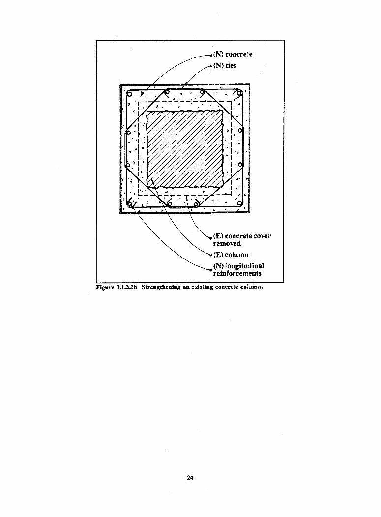
Figure 3.12.2b Strengthening an existing concrete column.
24
(N) concrete
(N) ties
(E) concrete coverremoved
(E) column
(N) longitudinalreinforcements

FIGURE 3.1.22b contlnued.
25

- 'A- ~~~~~(N) reinforcementI~~
I If 1_ (I 1 41' (N) footing tied to I 1 1 -F! existing footings - H 1 1
FIGURE 3.1.2.2c Strengthening an existing concrete frame buildingwith a reinforced concrete shear wall.
3.13 MOMENT FRAMES WITH INFILLS
3.13.1 Deficiencies
When reinforced concrete or steel moment frames are completely infilled, the frame action may be inhibited by
the rigidity of the infill wall. Rigid infill walls (e.g., reinforced concrete, reinforced masonry, or clay tile) will
resist lateral forces predominantly as shear walls and the frames will be relatively ineffective. Reinforced
concrete or steel frames completely infilled with less rigid walls (e.g., unreinforced masonry) will tend to resist
lateral forces as braced frames with a diagonal compression "strut" forming in the infill. The principal
deficiencies in moment frames with intfill walls are:
* Crushing of the infill at the upper and lower corners due to the diagonal compression strut type action ofthe infill wall,
* Shear failure of the beam/column connection in the steel frames or direct shear transfer failure of the beam
or column in concrete frames,
26

* Tensile failure of the columns or their connections due to the uplift forces resulting from the braced frameaction induced by the infill,
* Splitting of the infill due to the orthogonal tensile stresses developed in the diagonal compressive strut, and
* Loss of infill by out-of-plane forces due to loss of anchorage or excessive slenderness of the infill wall.
If the infill walls have inadequate capacity to resist the prescribed forces, the deficiencies may be correctedas described below for shear walls.
Partial height infills or infills with door or window openings also will tend to brace concrete or steel frames,but the system will resist lateral forces in a manner similar to that of a knee-braced frame. The lateral stiffnessof the shortened columns is increased so that, for a given lateral displacement, a larger shear force is developedin the shortened column compared to that in a full height column. If the column is not designed for thiscondition, shear or flexural failure of the column could occur in addition to the other potential deficienciesindicated above for completely infilled frames.
Falling debris resulting from the failure of an existing infill wall also poses a life-safety hazard. Frames maybe infilled with concrete or various types of masonry such as solid masonry, hollow clay tile, or gypsum masonry.These infills may be reinforced, partially reinforced, or unreinforced. Infills (particularly brittle unreinforcedinfills such as hollow clay tile or gypsum masonry) often become dislodged upon failure of the wall in shear.Once dislodged, the broken infill may fall and become a life-safety hazard. Mitigation of this hazard can beaccomplished by removing the infill and replacing it with a nonstructural wall as described above. The infill canalso be "basketed" by adding a constraining member such as a wire mesh. Basketing will not prevent the infillfrom failing but will prevent debris from falling.
In some cases, the exterior face of the infill may extend beyond the edge of the concrete or steel framecolumns or beams. For example, an unreinforced brick infill in a steel frame may have one wythe of brickbeyond the edge of the column or beam flange to form a uniform exterior surface. This exterior wythe isparticularly vulnerable to delamination or splitting at the collar joint (i.e., the vertical mortar joint between thewythes of brick) as the infilled frame deforms in response to lateral loads. Because the in-plane deformationof completely infilled frames is very small, the potential for delamination, is greater for partial infills or those withsignificant openings. The potential life-safety hazard for this condition should be evaluated and may be mitigatedas described in the preceding paragraph.
3.13.2 Rehabilitation Techniques for the Infill Walls of Moment Frames
Techniques. Inadequate shear transfer of the infill walls of moment frames can be improved by:
1. Eliminating the hazardous effects of the infill by providing a gap between the infill and the frame andproviding out-of-plane support.
2. Treating the infill frame as a shear wall and correcting the deficiencies as described in Sec. 3.2.
Relative Merits. If the frame, without the infill wall, has adequate capacity for the prescribed forces, the mostexpedient correction is to provide a resilient joint between the column, upper beam, and wall to allow the elasticdeformation of the column to take place without restraint (Technique 1). This may be accomplished by cuttinga gap between the wall and the column and the upper beam and filling it with resilient material (out-of-planerestraint of the infill still must be provided) or by removing the infill wall and replacing it with a nonstructuralwall that will not restrain the column.
If the frame has insufficient capacity for the prescribed forces without the infill, then proper connection ofthe infill to the frame may result in an adequate shear wall. The relative rigidities of the shear wall and momentframes in other bays must be considered when distributing the lateral loads and evaluating the wall and framestresses.
27

3.1.4 PRECAST CONCRETE MOMENT FRAMES
3.1.4.1 Deficiency
The principal deficiency of precast concrete moment frames is inadequate capacity and/or ductility of the jointsbetween the precast units.
3.1.4.2 Strengthening Techniques for the Precast Concrete Moment Frames
Techniques. Deficient capacity and ductility of the precast concrete moment frame connections can be improvedby:
1. Removing existing concrete in the precast elements to expose the existing reinforcing steel, providingadditional reinforcing steel welded to the existing steel (or drilled and grouted), and replacing the removedconcrete with cast-in-place concrete.
2. Reducing the forces on the connections by providing supplemental vertical-resisting elements (i.e., additionalmoment frames, braces, or shear walls) as discussed in Sec. 3.4.
Relative Merits. Reinforcing the existing connections as indicated in Technique 1 generally is not cost-effectivebecause of the difficulty associated with providing the necessary confinement and shear reinforcement in theconnections. Providing supplemental frames or shear walls (Technique 2) generally is more cost-effective;however, the two alternatives may be utilized in combination.
3.2 VERTICAL-RESISTING ELEMENTS--SHEAR WALLS
Shear walls are structural walls designed to resist lateral forces parallel to the plane of the wall. There are fourprincipal types of shear walls: cast-in-place reinforced concrete or masonry shear walls; precast concrete shearwalls; unreinforced masonry shear walls; and shear walls in wood frame buildings.
3.2.1 REINFORCED CONCRETE OR REINFORCED MASONRY SHEAR WALLS
3.2.1.1 Deficiencies
The principal deficiencies of reinforced concrete or masonry shear walls are:
• Inadequate shear capacity,
• Inadequate flexural capacity, and
o Inadequate shear or flexural capacity in the coupling beams between shear walls or piers.
32.12 Strengthening Techniques for Shear Capacity
Techniques. Deficient shear capacity of existing reinforced concrete or reinforced masonry shear walls can beimproved by:
1. Increasing the effectiveness of the existing walls by filling in door or window openings with reinforcedconcrete or masonry (Figures 3.2.1.2a and 3.2.1.2b).
28

2. Providing additional thickness to the existing walls with a poured-in-place or pneumatically applied (i.e.,shotcrete) reinforced concrete overlay anchored to the inside or outside face of the existing walls (Figure3.2.1.2c).
3. Reducing the shear or flexural stresses in the existing walls by providing supplemental vertical-resistingelements (i.e., shear walls, bracing, or external buttresses) as discussed in Sec. 3.4.
Relative Merits. Techniques 1 and 2 generally will be more economical than Technique 3, particularly if they canbe accomplished without increasing existing foundations. If adequate additional capacity can be obtained byfilling in selected window or door openings without impairing the functional or aesthetic aspects of the building,this alternative probably will the most economical. If this is not feasible, Technique 3 should be considered.
The optimum applicationof this alternative would be close existingwhen adequate additional ca- opening withpacity could be obtained by a reinforced concrete orreinforced concrete overlay on reinforced masonrya selected portion of the out-side face of the perimeter wallswithout unduly impairing thefunctional or aesthetic qualitiesof the building and without theneed to increase the footing. Insome cases, restrictions maypreclude any change in theexterior appearance of thebuilding (e.g., a building withhistorical significance). Inthese cases, it will be necessaryto consider overlays to theinside face of the exterior shearwalls or to either face of interi-or shear walls. Obviously thisis more disruptive and, thus, \ s wallmore costly than restricting the (N) shearwallwork to the exterior of the foundation to bebuilding. However, if the func- strengthened astional activities within the build- requireding are to be temporarily relo-cated because of other interioralterations, the cost differencebetween the concrete overlay to (E) reinforcedthe inside face and the outsideface of the building walls is concrete orreduced. In some cases, for reinforcedexample, when deficiencies exist masonry wallin the capacity of the diaphra-gm chords or in the shear tran- FIGURE 3.2.1.2a Strengthening an existing shear wall by filling in existingsfer from the diaphragm to the openings.shear walls, there may be com-pelling reasons to place the overlay on the inside face and concurrently solve other problems.
Technique 3 (i.e., providing supplemental vertical-resisting elements) usually involves construction of addi-tional interior shear walls or exterior buttresses. This alternative generally is more expensive than the other twobecause of the need for new foundations and for new drag struts or other connections to collect the diaphragmshears for transfer to the new shear walls or buttresses. The foundation required to resist overturning forces
29

for an exterior buttress usually is significant because the dead weight of the building cannot be mobilized to resistthe overturning forces. Piles or drilled piers may be required to provide tensile hold-down capacity for thefootings. Buttresses located on both ends of the wall can be designed to take compression only, minimizing thefoundation problems. Buttresses frequently are not feasible due to adjacent buildings or property lines. Theadvantages of the buttress over a new interior shear wall is that the work can be accomplished with minimalinterference to ongoing building functions.
-' - *. . .� ..-. \D �. \,\ \ 0' -
'�. \ �N" \X
'�N '� N''
(N) dowel, epoxygrouted in drilledholes
if steel lintel exist,weld (N) dowelsto lintel 41
ELEVATION
FIGURE 3.2.112b Example of details for enclosing an existing opening in areinforced concrete or masonry wall.
30
SECTION

FIGURE 3.2.m2c Strengthening an existingconcrete or masonry wall.
3.2.1.3 Strengthening Technique For Flexural Capacity
Deficient flexural capacity of existing reinforced concrete or masonry shear walls can be improved using the sametechniques identified to improve shear capacity, ensuring that flexural steel has adequate connection capacitiesinto existing walls and foundations. Shear walls that yield in flexure are more ductile than those that yield inshear. Shear walls that are heavily reinforced (i.e., with a reinforcement ratio greater than about 0.005) also aremore susceptible to brittle failure; therefore, care must be taken not to overdesign the flexural capacity ofrehabilitated shear walls.
3.2.1.4 Rehabilitation Technique for Coupling Beams
Deficient shear or flexural capacity in coupling beams of reinforced concrete or reinforced masonry shear wallscan be improved by:
1. Eliminating the coupling beams by filling in openings with reinforced concrete (Figure 3.2.1.2b).
2. Removing the existing beams and replacing with new stronger reinforced beams (Figure 3.2.1.4).
3. Adding reinforced concrete to one or both faces of the wall and providing an additional thickness to theexisting wall (Figure 3.2.1.2c).
4. Reducing the shear or flexural stresses in the connecting beams by providing additional vertical-resistingelements (i.e., shear walls, bracing, or external buttresses) as discussed in Sec. 3.4.
Relative Merits. If the deficiency is in both the piers and the connecting beams, the most economical solutionis likely to be the Technique 3 (i.e., adding reinforced concrete on one or both sides of the existing wall).Shallow, highly stressed connecting beams may have to be replaced with properly reinforced concrete as part of
31

the additional wall section. The new concrete may be formed and poured in place or may be placed by thepneumatic method.
If the identified deficiencyexists only in the connectingbeams, consideration should begiven to acceptance of someminor damage in the form ofcracking or spalling by repeat-ing the structural evaluationwith the deficient beams mod-eled as pin-ended links betweenthe piers. If this condition isunacceptable, Technique 2 maybe the most economical and thebeams should be removed andreplaced with properly designedreinforced concrete.
Depending on functionaland architectural as well asstructural considerations, Tech-nique 1 (i.e., filling in selected
openings) may be practical. IfTechniques 1 through 3 are notfeasible or adequate to ensurethe proper performance of thewall, reducing the stresses byadding supplemental new struc-tural elements (Technique 4)should be considered. Thisalternative is likely to be themost costly because of the needfor new foundations, verticalmembers, and collectors.
3.2.2 PRECAST CONCRETESHEAR WALLS
concrete floor
stirrup ties
reinforcedcrete couplingrm, tied to existingi and wall
(E) concrete wall FEN
(E) opening
(E) concrete slabbeyond )
ELEVATIONFIGURE 3.2.1.4 Example of strengthening an existing coupling beam at anexterior wall.
(E)
I~ ~ , co NeSECTION b j sab
I
322.1 Deficiencies
The principal deficiencies of precast concrete shear walls are:
* Inadequate shear or flexural capacity in the wall panels,
* Inadequate interpanel shear or flexural capacity,
o Inadequate out-of-plane flexural capacity, and
* Inadequate shear or flexural capacity in coupling beams.
32

3.2.22 Strengthening Techniques for Inadequate Shear or Flexural Capacity
Techniques. Deficient in-plane shear or flexural capacity of precast concrete panel walls can be improved by:
1. Increasing the shear and flexural capacity of walls with significant openings for doors or windows by infihlingthe existing openings with reinforced concrete.
2. Increasing the shear or flexural capacity by adding reinforced concrete (poured-in-place or shotcrete) at theinside or outside face of the existing walls.
3. Adding interior shear walls to reduce the flexural or shear stress in the existing precast panels.
Relative Merits. Precast concrete shear walls generally only have high in-plane shear or flexure stress when thereare large openings in the wall and the entire shear force tributary to the wall is carried by a few panels. Themost cost-effective solution generally is to infill some of the openings with reinforced concrete (Technique 1).In the case of inadequate interpanel shear capacity, the panels will act independently and can have inadequateflexural capacity. Improving the connection capacity between panels can improve the overall wall capacity.Techniques 2 and 3 generally not cost-effective unless a significant overstress condition exists.
3.2.2.3 Strengthening Techniques for Inadequate Interpanel Capacity
Techniques. Deficient interpanel shear connection capacity of precast concrete wall panels can be improved by:
1. Making each panel act as a cantilever to resist in-plane forces (this may be accomplished by adding orstrengthening tie-downs, edge reinforcement, footings, etc.).
2. Providing a continuous wall by exposing the reinforcing steel in the edges of adjacent units, adding ties, andrepairing with concrete.
Relative Merits. The two techniques can be equally effective. Where operational and aesthetic requirements forthe space can accommodate the installation of tie-downs and possibly surface-mounted wall edge reinforcementthat will make each panel act as a cantilever is a cost-effective way to compensate for inadequate interpanelcapacity. Where this is not acceptable, creating a continuous wall by exposing horizontal reinforcing steel andweld-splicing them across panel joints is a viable, although more costly, option. A commonly used technique toincrease interpanel capacity is to bolt steel plates across panel joints; however, observations of earthquakedamage indicate this technique may not perform acceptably due to insufficient ductility and its use is notrecommended.
3.2.2.4 Strengthening Techniques for Inadequate Out-of-Plane Flexural Capacity
Techniques. Deficient out-of-plane flexural capacity of precast concrete shear walls can be by:
1. Providing pilasters at and/or in-between the interpanel joints.
2. Adding horizontal beams between the columns or pilasters at mid-height of the wall.
Relative Merits. The reinforcing in some precast concrete wall panels may be placed to handle lifting stresseswithout concern for seismic out-of-plane flexural stresses. A single layer of reinforcing steel, for example, maybe placed adjacent to one face of the wall. If this condition exists, new and/or additional pilasters can beprovided between the diaphragm and the foundation at a spacing such that the wall will adequately spanhorizontally between pilasters. Also, horizontal beams can be provided between the pilasters at a vertical spacingsuch that the wall spans vertically between the diaphragm and the horizontal beam or between the horizontal
33

beam and the foundation. It should be noted that the problem of inadequate out-of-plane flexural capacity oftenis caused by wind design, particularly in the lower seismic zones.
32.2.S Strengthening Techniques for Inadequate Shear or Flexural Capacity in Coupling Beams
Techniques. Deficient shear or flexural capacity in coupling beams in precast concrete walls can be improvedusing the techniques identified for correcting the same condition in concrete shear walls.
Relative Merits. The relative merits of the alternatives for improving the shear or flexural capacity of connectingbeams in precast concrete coupling beams are similar to those discussed in Sec. 3.2.1.4 for concrete shear walls.
3.2.3 UNREINFORCED MASONRY SHEAR WALLS
3.2.3.1 Deficiencies
Masonry walls include those constructed of solid or hollow units of brick or concrete. Hollow clay tile also istypically classified as masonry. The use of hollow tile generally has been limited to nonstructural partitions andis discussed in Sec. 5.4. Unreinforced concrete, although not classified as masonry, may be strengthened bytechniques similar to those described below for masonry.
The principal deficiencies of unreinforced masonry shear walls are:
o Inadequate in-plane shear and
* Inadequate out-of-plane flexural capacity of the walls.
A secondary deficiency is inadequate shear or flexural capacity of the coupling beam.
3.23.2 Strengthening Techniques for Inadequate In-plane Shear and Out-of-Plane Flexural Capacity of theWalls
Techniques. Deficient in-plane shear and out-of-plane flexural capacity of unreinforced masonry walls can beimproved by:
1. Providing additional shear capacity by placing reinforcing steel on the inside or outside face of the wall andapplying new reinforced concrete (Figure 3.2.1.2c).
2. Providing additional capacity for only out-of-plane lateral forces by adding reinforcing steel to the wallutilizing the center coring technique (Figure 3.2.3.2).
3. Providing additional capacity for out-of-plane lateral forces by adding thin surface treatments (e.g., plasterwith wire mesh and portland cement mortar) at the inside and outside face of existing walls.
4. Filling in existing window or door openings with reinforced concrete or masonry (Figures 3.2.1.2a and3.2.1.2b).
5. Providing additional shear walls at the interior or perimeter of the building or providing external buttresses.
Relative Merits. Strengthening techniques for inadequate in-plane shear capacity are similar to those discussedabove for reinforced concrete or masonry walls, but there is an important difference because of the very lowallowable stresses normally permitted for unreinforced masonry. These stresses generally are based on the
34
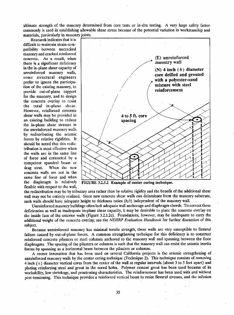
ultimate strength of the masonry determined from core tests or in-situ testing. A very large safety factorcommonly is used in establishing allowable shear stress because of the potential variation in workmanship andmaterials, particularly in masonry joints.
Research indicates that it isdifficult to maintain strain com-patibility between uncrackedmasonry and cracked reinforcedconcrete. As a result, when (E) unreinforcedthere is a significant deficiency masonry wallin the in-plane shear capacity of (unreinforced masonry walls, / (N) 4 inch (±) diametersome structural engineers core drilled and groutedprefer to ignore the participa- / with a polyester-sandtion of the existing masonry, to mixture with steelprovide out-of-plane support reinforcementfor the masonry, and to design /the concrete overlay to resist /the total in-plane shear. /However, reinforced concrete ,\shear walls may be provided in / 4 to 5 ft. corean existing building to reduce spacingthe in-plane shear stresses inthe unreinforced masonry wallsby redistributing the seismicforces by relative rigidities. Itshould be noted that this redis-Itribution is most effective whenthe walls are in the same lineof force and connected by acompetent spandrel beam ordrag strut. When the newconcrete walls are not in thesame line of force and whenthe diaphragm is relatively FIGURE 323.2 Example of center coring technique.flexible with respect to the wall,the redistribution may be by tributary area rather than by relative rigidity and the benefit of the additional shearwall may not be entirely realized. Since new concrete shear walls can delaminate from the masonry substrate,such walls should have adequate height to thickness ratios (h/t) independent of the masonry wall. -
Unreinforced masonry buildings often lack adequate wall anchorage and diaphragm chords. To correct thesedeficiencies as well as inadequate in-plane shear capacity, it may be desirable to place the concrete overlay on
the inside face of the exterior walls (Figure 3.2.1.2c). Foundations, however, may be inadequate to carry theadditional weight of the concrete overlay; see the NEHRP Evaluation Handbook for further discussion of thissubject.
Because unreinforced masonry has minimal tensile strength, these walls are very susceptible to flexuralfailure caused by out-of-plane forces. A common strengthening technique for this deficiency is to constructreinforced concrete pilasters or steel columns anchored to the masonry wall and spanning between the floordiaphragms. The spacing of the pilasters or columns is such that the masonry wall can resist the seismic inertiaforces by spanning as a horizontal beam between the pilasters or columns.
A recent innovation that has been used on several California projects is the seismic strengthening ofunreinforced masonry walls by the center coring technique (Technique 2). This technique consists of removing4 inch (±) diameter vertical cores from the center of the wall at regular intervals (about 3 to 5 feet apart) andplacing reinforcing steel and grout in the cored holes. Polymer cement grout has been used because of itsworkability, low shrinkage, and penetrating characteristics. The reinforcement has been used with and withoutpost-tensioning. This technique provides a reinforced vertical beam to resist flexural stresses, and the infusion
35

of the polymer grout strengthens the mortar joint in the existing masonry, particularly in the vertical collar jointsthat generally have been found to be inadequate. This method is a developing technology and designerscontemplating its use should obtain the most current information on materials and installation techniques.
Technique 3 for strengthening the out-of-plane capacity of existing walls is to apply thin surface treatmentsof plaster or portland cement over welded wire mesh. These treatments should be applied on both faces ofexisting walls.
Filling in existing window and/or door openings (Technique 4) can be a cost-effective means of increasingin-plane shear capacity if the architectural and functional aspects of the building can be accommodated. Tomaintain strain compatibility around the perimeter of the opening, it is desirable. that the infill material havephysical properties similar to those of the masonry wall.
3.2.3.3 Alternative Methodology for Evaluation and Design of Unreinforced Masonry Bearing Wall Buildings
An alternative methodology has been developed for the evaluation and design of unreinforced masonry bearingwall buildings with flexible wood diaphragms. Initially designated as the "ABK Methodology," it is based onresearch funded by the National Science Foundation and performed by Agbabian Associates, S. B. Barnes andAssociates, and Kariotis and Associates. The ABK methodology was the basis for the City of Los Angeles' Ruleof General Application (RGA) that was developed in cooperation with the Hazardous Buildings Committee ofthe Structural Engineers Association of Southern California and approved in 1987 as an alternate to theconventional design method in Division 88 of the Los Angeles City Building Code. Code provisions for the "ABKMethodology" now have been developed jointly by the Structural Engineers Association of California (SEAOC)and the California Building Officials (CALBO) and are published in the 1991 Edition of the Uniform Code forBuilding Conservation (available from the International Conference of Building Officials). The procedure forevaluation of unreinforced masonry (URM) bearing wall buildings presented in Appendix C of the NEHRPEvaluation Handbook is based on this methodology.
Some of the principal differences between the new methodology and conventional code provisions are asfollows:
1. The in-plane masonry walls are assumed to be rigid (i.e., there is no dynamic amplification of the groundmotion in walls above ground level).
2. The diaphragms and the tributary masses of the out-of-plane walls respond to ground motion through theirattachments to the in-plane walls.
3. The maximum seismic force transmitted to the in-plane walls by the diaphragm is limited by the shearstrength of the diaphragms.
4. The diaphragm response is controlled within prescribed limits by cross walls (i.e., existing or new woodsheathed stud walls) or shear walls.
5. Maximum height to thickness (hit) ratios are specified in lieu of flexural calculations for the out-of-planeresponse of the walls.
The ABK Methodology and the more conventional evaluation and design methods, prescribed in buildingcodes such as the City of Los Angeles' Division 88 for unreinforced masonry have been prescribed in Californiawith the objective of preservation of life safety rather than prevention of damage. Several moderate earthquakesin Southern California have provided limited testing of the methodology and, although the results are notconclusive, very few of the retrofitted buildings suffered total or partial collapse and the degree of structuraldamage was less than occurred in nonretrofitted buildings.
36

3.2.4 SHEAR WALLS IN WOOD FRAME BUILDINGS
3.2.4.1 Deficiencies
The principal deficiencies of wood or metal stud shear wall buildings are:
* Inadequate shear capacity of the wall and
* Inadequate uplift or hold-down capacity of the wall.
3.2.42 Strengthening Techniques for Inadequate Shear Capacity
Techniques. Deficient shear capacity of the wood or metal stud walls can be improved by:
1. Increasing the shear capacity by providing additional nailing to the existing finish material.
2. Increasing the shear capacity by adding plywood sheathing to one or both sides of the wall.
3. Reducing the loads on the wall by providing supplemental shear walls to the interior or perimeter of thebuilding.
Relative Merits. Seismic forces in existing wood frame buildings generally are moderate and, in many cases, theexisting walls may be adequate. Tabulated allowable shear values are available for existing finishes such as lathand plaster and gypsum wallboard. In the latter case, existing nailing may dictate the allowable shear value andhigher allowable values may be obtained by additional nailing. Similarly, the allowable shear value for walls withexisting plywood sheathing may be increased within limits by additional nailing. New plywood sheathing maybe nailed onto existing gypsum wallboard. Longer nails are required and the allowable shear values arecomparable to plywood nailed directly to the studs, but the existing finish need not be removed.
Existing metal stud shear walls may be evaluated like wood stud walls. The fasteners generally are self-threading sheet metal screws and corresponding allowable shear values are available for the finishes discussedin the preceding paragraph.
Where the shear capacity of an existing wall is increased, the shear transfer capacity at the foundation andthe capacity of the foundation connection to resist overturning forces must be checked. Techniques forincreasing the foundation shear connection and overturning capacities are discussed in Sec. 3.8.1.
As with other shear wall strengthening techniques, the most economical scheme will be the one thatminimizes the total cost, including removal and replacement of finishes and other nonstructural items, disruptionof the functional use of the building, and any necessary strengthening of foundations or other structural supports.Under normal circumstances, sheathing the exterior face of the perimeter walls should have the lowest cost, butin some circumstances (e.g., if extensive interior alterations are planned) strengthening existing interior shearwalls or adding new interior shear walls will be more economical.
If the loads are so large that the above alternatives are not practical, it may be possible to reduce the forceson the wall by strengthening other existing shear walls or by adding supplemental walls (Technique 3).
3.2.43 Strengthening Techniques for Inadequate Uplift or Hold-Down Capacity
Techniques. Strengthening techniques for inadequate uplift or hold-down capacity are discussed in Sec. 3.7.1.5and are illustrated in Figures 3.7.1.5 (a, b, c, and d).
37
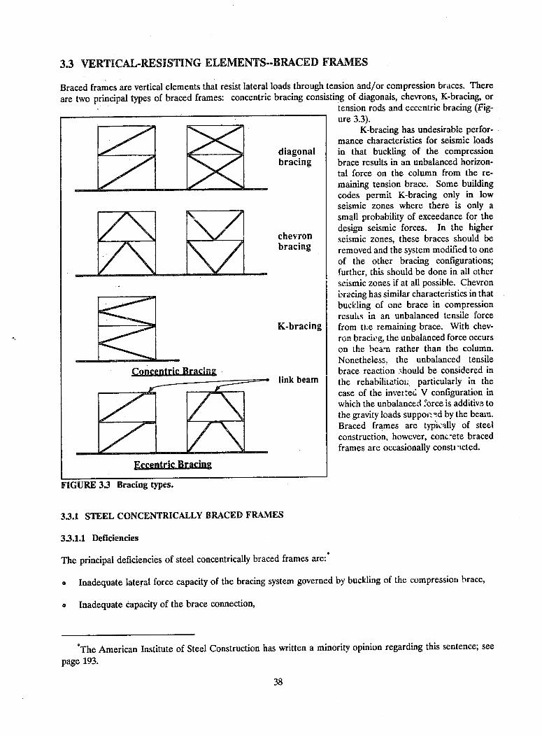
3.3 VERTICAL-RESISTING ELEMENTS--BRACED FRAMES
Braced frames are vertical elements that resist lateral loads through tension and/or compression braces. There
are two principal types of braced frames: concentric bracing consisting of diagonals, chevrons, K-bracing, ortension rods and eccentric bracing (Fig-ure 3.3).
K-bracing has undesirable perfor-mance characteristics for seismic loads
diagonal in that buckling of the compressionbracing brace results in an unbalanced horizon-
tal force on the column from the re-- _ maining tension brace. Some building
codes permit K-bracing only in lowseismic zones where there is only asmall probability of exceedance for thedesign seismic forces. In the higher
chevron seismic zones, these braces should beD\ D bracing removed and the system modified to one
of the other bracing configurations;___________ - _further, this should be done in all other
seismic zones if at all possible. Chevronbracing has similar characteristics in thatbuckling of one brace in compressionresults in an unbalanced tensile force
K-bracing from tMe remaining brace. With chev-ron bracing, the unbalanced force occurson the beam rather than the column.Nonetheless. the unbalanced tensile
ConcentricBracing brace reaction Should be considered inlink beam the rehabilitatioi.. particularly in the
case of the inverted V configuration inwhich the unbalanced force is additive tothe gravity loads suppornad by the beam.Braced frames are typically of steelconstruction, however, conc.ete bracedframes are occasionally consti icted.
Eccntric Bracing
FIGURE 33 Bracing types.
3.3.1 STEEL CONCENTRICALLY BRACED FRAMES
3.3.1.1 Deficiencies
The principal deficiencies of steel concentrically braced frames are:
* Inadequate lateral force capacity of the bracing system governed by buckling of the compression brace,
* Inadequate capacity of the brace connection,
*The American Institute of Steel Construction has written a minority opinion regarding this sentence; see
page 193.
38

o Inadequate axial load capacity in the columns or beams of the bracing system, and
* Brace configuration that results in unbalanced tensile forces, causing bending in the beam or column whenthe compression brace buckles.
33.12 Strengthening Techniques for Inadequate Brace Capacity
Techniques. Deficient brace compression capacity can be improved by:
1. Increasing the capacity of the braces by adding new members thus increasing the area and reducing theradius of gyration of the braces.
2. Increasing the capacity of the member by reducing the unbraced length of the existing member by providingsecondary bracing.
3. Providing greater capacity by removing and replacing the existing members with new members of greatercapacity (Figure 3.3.1.2).
4. Reducing the loads on the braces by providing supplemental vertical-resisting elements (i.e., shear walls,bracing, or eccentric bracing) as discussed in Sec. 3.4.
FIGURE 33.12 Addition to or replacement of an existing X-brace.
39
(N) weld
(N) connection plate,-b'
- -
A

Relative Merits. A brace member is designed to resist both tension and compression forces, but its capacity forcompression stresses is limited by potential buckling and is therefore less than the capacity for tensile stresses.Since the design of the system generally is based on the compression capacity of the brace, some additionalcapacity may be obtained by simply reducing the unsupported length of the brace by means of secondary bracing(Technique 3) provided the connections have adequate reserve capacity or can be strengthened for the additionalloads.
If significant additional bracing capacity is required, it will be necessary to consider strengthening (Technique1) or replacement (Technique 3) of the brace. Single-angle bracing can be doubled; double-angle bracing canbe "starred"; channels can be doubled; and other rolled sections can be cover plated. New sections should bedesigned to be compact if possible since they will perform with significantly more ductility than noncompactsections. These modifications probably will require strengthening or redesign of the connections. The othermembers of the bracing system (i.e., columns and beams) must be checked for adequacy with the new bracingloads. Strengthening of existing K- or chevron bracing should be undertaken only after careful evaluation of theadditional bending forces following the buckling of the compression bracing. Where the existing bracing in thesesystems is found to have inadequate capacity, the preferred solution is to replace it with a diagonal or cross-brac-ing configuration.
It usually is a good idea to limit the strengthening of the existing bracing to the capacity of the othermembers of the bracing system and the foundations and to provide additional bracing if required. An alternativewould be to provide new shear walls or eccentric bracing. Construction of supplemental shear walls may bedisruptive and probably will require new foundations. The greater rigidity of the shear walls as compared withthat of the bracing also may tend to make the existing bracing relatively ineffective. The rigidity of eccentricbracing, however, can be "tuned" to be compatible with that of the existing concentric bracing, but the advantagesof the eccentric bracing may be offset by its greater construction cost. Thus, strengthening the existing bracingor providing additional concentric bracing are considered to be the most cost-effective alternatives.
3.3.1.3 Strengthening Techniques for Inadequate Capacity of the Brace Connection
Techniques. Deficient brace connection capacity can be improved by:
1. Increasing the capacity of the connections by additional bolting or welding.
2. Increasing the capacity of the connections by removing and replacing the connection with members ofgreater capacity.
3. Reducing the loads on the braces and their connections by providing supplemental vertical-resisting elements(i.e., shear walls, bracing, or eccentric bracing) as discussed in Sec. 3.4.
Relative Merits. Adequate capacity of brace connections is essential to the proper performance of the brace.The capacity of the brace is limited by its compression capacity and the connection may have been designed forthis load. When the brace is loaded in tension, however, the brace may transmit significantly higher forces tothe connection. If the existing connection members (e.g., gusset plates) have sufficient capacity, the mosteconomical alternative may be to increase the existing connection capacity by providing additional welding orbolts. If the existing gusset plates have inadequate capacity, the existing configuration and accessibility need tobe assessed to determine whether adding supplemental connecting members or replacing the existing connectingmembers with members of greater capacity (Technique 3) is more economical. If the existing brace membersrequire strengthening or replacement with members of greater capacity, it is probable that new connectionswould bethe most cost-effective alternative.
Whether Technique 1 (reducing loads by adding supplemental members) is a cost-effective alternative ismost likely to be a consideration when assessing the capacities of the braces, not the brace connections. Themerits of this alternative are discussed above.
40
33.1A Strengthening Techniques for Inadequate Axial Load Capacity In the Columns or Beams of the BracingSystem
Techniques. Deficient axial load capacity of existing bracing system columns and beams can be improved by.
1. Providing additional axial load capacity by adding cover plates to the member flanges or by boxing theflanges.
2. Providing additional axial load capacity by jacketing the existing members with reinforced concrete.
3. Reducing the loads on the beams and columns by providing supplemental vertical-resisting elements (i.e.,shear walls, bracing, or eccentric bracing) as discussed in Sec. 3.4.
Relative Merits. The most cost-effective alternative for increasing the capacity of the existing beams and columnsin a concentrically braced frame system is to add cover plates to or box the flanges (Technique 1). The effortinvolved in adding cover and box plates includes removing the existing fireproofing and nonstructural obstruc-tions. Jacketing of existing members with reinforced concrete (Technique 2) would seldom be cost-effective dueto the significant forming effort required. The relative merits of reducing the loads by providing supplementalmembers is discussed in Sec. 3.3.1.2.
33.2 ROD OR OTHER TENSION BRACING
33.2.1 Deficiencies
The principal deficiencies of rod or other tension bracing systems are:
* Inadequate tension capacity of the rod, tensile member, or its connection and
* Inadequate axial capacity of the beams or columns in the bracing system.
33.2.2 Strengthening Techniques for Tension Capacity
Techniques. Deficient tension capacity of the rod or other tension member and its connection can be improvedby.
1. Increasing the capacity by strengthening the existing tension members.
2. Increasing the capacity by removing the existing tension members and replacing with new members ofgreater capacity.
3. Increasing the capacity by removing the existing tension member and replacing it with diagonal or X-bracingcapable of resisting compression as well as tension forces.
4. Reducing the forces on the existing tension members by providing supplemental vertical-resisting elements(i.e., additional tension rods) as discussed in Sec. 3.4.
Relative Merits. Tension bracing is commonly found in light industrial steel frame buildings including somedesigned for prefabrication. The most common deficiency is inadequate tensile capacity in the tension rods.These rods generally are furnished with upset ends so that the effective area is in the body of the rod rather thanat the root of the threads in the connection. It therefore is rarely feasible to strengthen a deficient rod(Technique 1); hence, correction of the deficiency likely will require removal and replacement with larger rods(Technique 2), removal of existing tension bracing and replacement with new bracing capable of resisting tension
41
and compression (Technique 3), or installation of additional bracing (Technique 4). When replacing existingtension braces with new braces capable of resisting tension and compression it is good practice to balance themembers (i.e., design the system such that approximately the same number of members act in tension as incompression). Increasing the size of the bracing probably will require strengthening of the existing connectiondetails and also will be limited by the capacity of the other members of the bracing system or the foundationsas discussed above for ordinary concentric bracing. The effectiveness of replacing the tension bracing withmembers capable of resisting compression forces depends on the length of the members and the need forsecondary members to reduce the unbraced lengths. Secondary members may interfere with existing windowor door openings. The most cost-effective technique for correction of the deficiency probably will be to provideadditional bracing (Technique 4) unless functional or other nonstructural considerations (e.g., obstruction ofexisting window or door openings) preclude the addition of new bracing.
3.3.2.3 Strengthening Techniques for Beam or Column Capacity
Techniques. Deficient axial capacity of the beams or columns of the bracing systems can be improved by:
1. Increasing the axial capacity by adding cover plates to or by boxing the existing flanges.
2. Reducing the forces on the existing columns or beams by providing supplemental vertical-resisting elements(i.e., braced frames or shear walls) as discussed in Sec. 3.4.
Relative Merits. Reinforcing the existing beams or columns with cover plates or boxing the flanges generally isthe most cost-effective alternative. If supplemental braces or shear walls are required to reduce stresses in otherstructural components such as the tension rods or the diaphragm, the addition of supplemental vertical-resistingelements may be a viable alternative.
3.33 ECCENTRIC BRACING
333.1 Deficiency
The primary deficiency of an eccentrically braced frame system is likely to be nonconformance with currentdesign standards because design standards for such elements did not exist earlier than about 1980. Eccentricbracing in older buildings may not have the desired degree of ductility.
33.3.2 Strengthening Techniques for Eccentric Braced Frames
Techniques. An existing eccentrically braced frame system can be brought into conformance with current designstandards by ensuring that the system is balanced (i.e., there is a link beam at one end of each brace), the braceand the connections are designed to develop shear or flexural yielding in the link, the connection is a full momentconnection where the link beam has an end at a column, and lateral bracing is provided to prevent out-of-planebeam displacements that would compromise the intended action. Alternatively, the loads on the existingeccentrically braced frame can be reduced by providing supplemental vertical-resisting elements such asadditional eccentrically braced frames.
Relative Mefits. The use of engineered eccentric bracing is a relatively recent innovation (within about 10 years)that can provide the rigidity associated with concentric bracing as well as the ductility associated with momentframes. The recommended design of these frames precludes compressive buckling of the brace members byshear yielding of a short portion of the horizontal beam (the link beam). If the brace is in a diagonalconfiguration, the yielding occurs in the horizontal beam between the brace connection and the adjacent column;if it is in a chevron configuration, the yielding occurs in the beam between the two brace connections.
42

Because this system is relatively new, a deficiency in the lateral load capacity reflects either improper designor upgraded design criteria. A properly designed eccentric bracing system balances the yield capacity of thehorizontal link beam against the buckling capacity of the brace beam. It usually is not cost-effective to strengthenthe members of this bracing system unless it is necessary to correct a design defect (e.g, if the brace has beenover designed, the shear capacity of the horizontal beam can be increased by adding doubler plates to the beamweb provided other members of the system have adequate additional capacity). Usually it will be necessary toadd additional bracing. It should be noted, however, that although eccentric bracing is a desirable supplementto an existing concentric bracing system, concentric bracing is not desirable as a supplement to an existingeccentric bracing system. The proper functioning of an eccentric bracing system requires inelastic deformationsthat are not compatible with concentric bracing; the introduction of a ductile element (eccentric bracing) intoan existing "brittle" system (concentric bracing) is beneficial, but the reverse procedure is not the case. Theaddition of shear walls to an existing eccentric bracing system also is usually not effective because of their greaterrigidity. Thus, the most cost-effective procedure for increasing the capacity of an existing eccentric bracingsystem probably will be to provide additional eccentric bracing.
3A VERTICAL-RESISTING ELEMENTS--ADDING SUPPLEMENTAL MEMBERS
The lateral seismic inertial forces of an existing building are transferred from the floors and roofs through thevertical-resisting elements (i.e., shear walls, braced frames and moment frames) to the foundations and into theground. The forces in the individual shear walls, braced frames, and moment frames are a function of the weightand height of the building plus the number, size, and location of the elements. By adding new vertical elementsto resist lateral forces, the forces in the existing elements will be modified and generally will be reduced. Thus,the addition of supplemental vertical elements that will resist lateral loads can be a means to correct existingelements that are overstressed. The purpose of this section is to discuss the benefits and the problems associatedwith adding supplemental vertical-resisting elements to an existing building so that comparisons with otherrehabilitation techniques such as strengthening overstressed members or reducing demand can be placed inperspective. The two general categories of supplemental vertical-resisting elements are in-plane supplementalelements and new bay supplemental elements. The two categories are schematically portrayed in Figure 3.4.
The introduction of new in-plane supplemental elements into a building will primarily reduce the forces onthe existing vertical elements in the plane where the new element is added. Forces on other vertical-resistingelements, diaphragms, and the connections between them will be modified to a lesser degree depending on therelative rigidities of the vertical elements and the diaphragms. All wood and some steel deck diaphragms maybe considered "flexible" when used with masonry or concrete shear walls. Straight laid sheathing may be "flexible"with any type of construction, but plywood sheathed diaphragms may be considered rigid with wood frame wallsor light steel frame construction. Where diaphragms are flexible, the addition of a supplemental vertical elementin the plane of existing vertical elements will have essentially no effect on the forces in vertical elements locatedin other bays or on the diaphragms or the connections between the diaphragms and the vertical-resistingelements.
On the other hand, the introduction of new vertical bay supplemental elements, will reduce the forces onall the elements--existing vertical elements, diaphragms, foundations, and the connections between them. Thereduction in forces will be proportional to the relative rigidity of the vertical elements when the building has arigid diaphragm and will be proportional to the tributary areas associated with the vertical-resisting elementswhen the building has a flexible diaphragm.
The effect of adding in-plane supplemental elements or new bay supplemental elements on the lateral-forcedistribution of an existing building needs to be evaluated when considering whether to add new vertical elementsor to strengthen existing members to reduce demand on bracing elements.
43
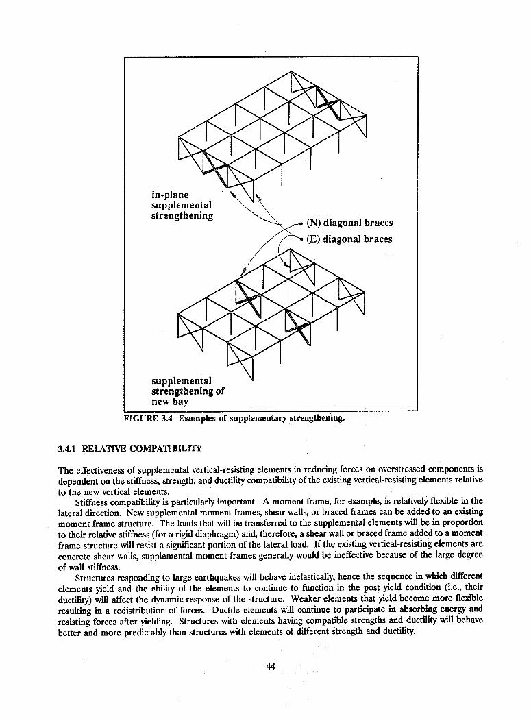
in-planesupplementalstrengthening (N) diagonal braces
(E) diagonal braces
supplementalstrengthening ofnew bay
FIGURE 3.4 Examples of supplementary strengthening.
3.4.1 RELATIVE COMPATIBILITY
The effectiveness of supplemental vertical-resisting elements in reducing forces on overstressed components is
dependent on the stiffness, strength, and ductility compatibility of the existing vertical-resisting elements relativeto the new vertical elements.
Stiffness compatibility is particularly important. A moment frame, for example, is relatively flexible in thelateral direction. New supplemental moment frames, shear walls, or braced frames can be added to an existing
moment frame structure. The loads that will be transferred to the supplemental elements will be in proportionto their relative stiffness (for a rigid diaphragm) and, therefore, a shear wall or braced frame added to a momentframe structure will resist a significant portion of the lateral load. If the existing vertical-resisting elements are
concrete shear walls, supplemental moment frames generally would be ineffective because of the large degreeof wall stiffness.
Structures responding to large earthquakes will behave inelastically, hence the sequence in which differentelements yield and the ability of the elements to continue to function in the post yield condition (i.e., their
ductility) will affect the dynamic response of the structure. Weaker elements that yield become more flexibleresulting in a redistribution of forces. Ductile elements will continue to participate in absorbing energy and
resisting forces after yielding. Structures with elements having compatible strengths and ductility will behave
better and more predictably than structures with elements of different strength and ductility.
44

3A.X EXTERIOR SUPPLEMENTAL ELEMENTS
The construction of exterior supplemental moment frames, shear walls, or braced frames has many advantages.Exterior elements can be as effective in reducing loads on other elements as interior elements; yet, constructionmay be significantly less costlyand access for equipment andmaterials will be significantlyeasier than for interior con-struction. Perhaps the singlebiggest advantage of exteriorsupplemental elements is that (N) collectordisruption of the functional useof the interior of the buildingwill be minimized both duringand after construction. Figure3.4.2 shows the addition of anexterior supplemental concreteshear wall to an existing con-crete or masonry building.Steel structures also can beused as buttresses.
There are, however, inher-ent problems in constructing (E) reinforcedsupplemental exterior shear concrete orwalls, braced frames, and mo- unreinforcedment frames. Many buildings masonry walldo not have the necessary space / , (N) tension tie toto accommodate exterior struc- building each sidetures due to the location of ' I of buttressadjacent buildings or propertylines. New exterior elements (N) concrete, masonryalso may significantly affect the or1 L ()steel buttress wallarchitectural aesthetics of the I (N) piles or caissonsexterior of the building. if required
Supplemental elementsgenerally will require a signifi- FIGURE 3.4.2 Example of supplemental in-plane strengthening by thecant capacity to resist overturn- addition of an external buttress.ing forces. Elements awayfrom the building (e.g., the end of a buttress wall) will not be able to mobilize the dead weight of the buildingto resist the overturning forces, and significant uplift capacity therefore may be required in the new foundation.
The construction of exterior elements also does not preclude the need for interior construction. A load pathmust be provided to transfer forces from the existing building elements to the new external vertical-resistingelements. This usually necessitates the construction of collectors on the interior of the building.
3.4.3 INTERIOR SUPPLEMENTAL ELEMENTS
The construction of interior supplemental moment frames, shear walls, or braced frames will involve significantdisruption of the functional operation of the building. Existing architectural coverings will need to be removedand new foundations constructed along with the new frame or wall and necessary collectors. It usually isdesirable to locate new walls or frames along existing framing lines (i.e., framing into existing columns andbeams) in order to provide boundary members, collectors, and dead load to help resist overturning forces whiletaking advantage of existing column foundations. Figure 3.4.3 shows the addition of a supplemental reinforcedconcrete shear wall on the interior of an existing concrete building. It should be noted that all concrete poursare subject to consolidation and shrinkage and, in this detail, the concrete may sag away from the underside of
45

the concrete slab. This condition may be improved with proper mix design for low shrinkage or, alternatively,
the lower wall can be made in two pours 48 hours apart. The initial pour would be up to about 18 inches from
the slab soffit to allow sufficient space to form shear keys and to clean and prepare the surface for the followingpour to the top of the slab.
Functional considerations likely will dictate the location of interior supplemental elements. This is
particularly the case with shear walls or braced frames that will significantly break up the interior space.
FIGURE 3A.3 Connection of a supplemental interior shear wall.
3.5 DIAPHRAGMS
Diaphragms are horizontal subsystems that transmit lateral forces to the vertical-resisting elements. Diaphragms
typically consist of the floors and roofs of a building. In this handbook, the term "diaphragm" also includeshorizontal bracing systems. There are five principal types of diaphragms: timber diaphragms, concrete
diaphragms, precast concrete diaphragms, steel decking diaphragms, and horizontal steel bracing.Inadequate chord capacity is listed as a deficiency for most types of diaphragms. Theoretical studies, testing
of diaphragms, and observation of earthquake-caused building damage and failures provide evidence that the
commonly used method of determining diaphragm chord force (i.e., comparing the diaphragm to a flanged beam
46
(N) reinforcemente i * .' through drilled
'~ holes, drypack holes
(N) access hole inexisting slab for
. % . . placing concrete
. e . 0
. .. lroughen surface ofexisting slab
4u'.* .40
(N) shear wall
'- :, : (N) optional pour; - joint and shear
* key to reduceshrinkage effects
*.'.
II!,-'_r
I / 'I/.

and dividing the diaphragm moment by its depth) may lead to exaggerated chord forces and, thus, overemphasizethe need for providing an "adequate" boundary chord. Before embarking on the repair of existing chordmembers or the addition of new ones, the need for such action should be considered carefully with particularattention to whether the beam analogy is valid for calculating chord forces in the diaphragm under consideration.
Since few diaphragms have span-depth ratios such that bending theory is applicable, the capacity of thediaphragm to resist the tensile component of shear stress could be compared with tensile stresses derived fromdeep beam theory. In analyzing diaphragms by beam theory, chords provided by members outside of thediaphragms but connected to their edges may be considered and may satisfy the chord requirement.
3.5.1 TIMBER DIAPHRAGMS
3.5.1.1 Deficiencies
Timber diaphragms can be composed of straight laid or diagonal sheathing or plywood. The principaldeficiencies in the seismic capacities of timber diaphragms are:
* Inadequate shear capacity of the diaphragm,
* Inadequate chord capacity of the diaphragm,
* Excessive shear stresses at diaphragm openings or at plan irregularities, and
* Inadequate stiffness of the diaphragm resulting in excessive diaphragm deformations.
3.5.12 Strengthening Techniques ror Inadequate Shear Capacity
Techniques. Deficient shear capacity of existing timber diaphragms can be improved by:
1. Increasing the capacity of the existing timber diaphragm by providing additional nails or staples with dueregard for wood splitting problems.
2. Increasing the capacity of the existing timber diaphragm by means of a new plywood overlay.
3. Reducing the diaphragm span through the addition of supplemental vertical-resisting elements (i.e., shearwall or braced frames) as discussed in Sec. 3.4.
Relative Merits. Adding nails and applying a plywood overlay (Techniques 1 and 2) require removal andreplacement of the existing floor or roof finishes as well as removal of existing partitioning, but they generallyare less expensive than adding new walls or vertical bracing (Technique 3). If the existing system consists ofstraight laid or diagonal sheathing, the most effective alternative is to add a new layer of plywood since additionalnailing typically is not feasible because of limited spacing and edge distance. Additional nailing usually is theleast expensive alternative, but the additional capacity is still limited to the number and capacity of the additionalnails that can be driven (i.e., with minimum allowable end distance, edge distance, and spacing).
The additional capacity that can be developed by plywood overlays usually depends on the capacity of theunderlying boards or plywood sheets to develop the capacity of the nails from the new overlay. Higher shearvalues are allowed for plywood overlay when adequate nailing and blocking (i.e., members with at least 2 inchesof nominal thickness) can be provided at all edges where the plywood sheets abut. Adequate additional capacityfor most timber diaphragms can be developed using this technique unless unusually large shears need to beresisted. When nailing into existing boards, care must be taken to avoid splitting. If boards are prone tosplitting, pre-drilling may be necessary.
The addition of shear walls or vertical bracing in the interior of a building may be an economical alternativeto strengthening the diaphragms particularly if the additional elements can be added without the need to
47

strengthen the existing foundation. The alternative methodology described in Sec. 3.2.3.3 emphasizes control of
the existing diaphragm response by cross walls or shear walls rather than by strengthening and, in thatmethodology, the shear transmitted to the in-plane walls is limited by the strength of the diaphragm. Although
the methodology was developed for buildings with unreinforced masonry walls and flexible timber diaphragms,the above diaphragm provisions are considered to be generally applicable for timber diaphragms in buildings withother relatively rigid wall systems. When additional bracing or interior shear walls are required, relative economydepends on the degree to which ongoing operations can be isolated by dust .nd noise barriers and on the needfor additional foundations.
3.5.1.3 Strengthening Techniques for Inadequate Chord Capacity
Techniques. Deficient diaphragm chord capacity can be improved by
1. Providing adequately nailed or bolted continuity splices along joists or fascia parallel to the chord (Figure
3.5.1.3).
2. Providing a new continuous steel chord member along the top of the diaphragm.
3. Reducing the stresses on the existing chords by reducing the diaphragm's span through the addition of newshear walls or braced frames as discussed in Sec. 3.4.
Relative Merits. Wood diaphragms typically are constructed with minimal capacity to resist chord forces. Bottomwall plates nailed into the plywood are not spliced but butted; hence, the chord capacity provided at the bottomplate joints will be minimal. If the nailing between the bottom plate and the plywood is sufficient to transferchord forces, splicing the top plate can be a means to provide this chord capacity. Steel straps can be nailedacross the butted joint to provide this splice capacity, but notching of the bottom of some of the wood studs maybe necessary to install the splice plates.
Another alternative is to utilize the double top plates on the wall below the diaphragm as the chord member.
The double top plates typically are lapped and nailed. With sufficient lap nailing, the chord capacity of one plate
can be developed if an adequate path for shear transfer is provided between the diaphragm and the top plates.This load path can be provided by nailing such as that shown in Figure 3.5.1.3. New or existing nailing needs
to be verified or provided between the diaphragm sheathing, the edge blocking, the exterior sheathing, and thetop plates.
Simplified calculations to determine stresses in diaphragm chords conservatively consider the diaphragm asa horizontal beam and ignore the flexural capacity of the web of the diaphragm as well as the effect of the out-
of-plane shear walls that reduce the chord stresses. However, even though the chord requirements in somebuildings may be overstated, in most buildings a continuous structural element is required at diaphragmboundaries to collect the diaphragm shears and transfer them to the individual resisting shear walls along eachboundary (see Sec. 3.7.1).
A continuous steel member along the top of the diaphragm may be provided to function as a chord or
collector member. For existing timber diaphragms at masonry or concrete walls, the new steel members may
be used to provide wall anchorage as indicated in Figure 3.7.1.4b as wall as a chord or collector member for thediaphragm shear forces.
The lack of adequate chord capacity is seldom the reason why new shear walls or braced frames (Technique
3) would be considered to reduce the diaphragm loads. Reducing the diaphragm span and loads through theintroduction of new vertical-resisting elements, however, may be considered to address other member deficienciesand, if so, the chord inadequacy problem also may be resolved.
48

building.
3.5.1A Strengthening Techniques for Excessive Shear Stresses at Openings or Plan Irregularities
Techniques. Excessive shear stresses at diaphragm openings or other plan irregularities can be improved by:
1. Reducing the local stresses by distributing the forces along the diaphragm by means of drag struts (Figures3.5.1.4a and 3.5.1.4b).
2. Increasing the capacity of the diaphragm by overlaying the existing diaphragm with plywood and nailing theplywood through the sheathing at the perimeter of the sheets adjacent to the opening or irregularity.
3. Reducing the diaphragm stresses by reducing the diaphragm spans through the addition of supplementalshear walls or braced frames as discussed in Sec. 3.4.
Relative Merits. The most cost-effective way to reduce large local stresses at diaphragm openings or planirregularities is to install drag struts (Figures 3.5.1.4a and 3.5.1.4b), to distribute the forces into the diaphragm
49
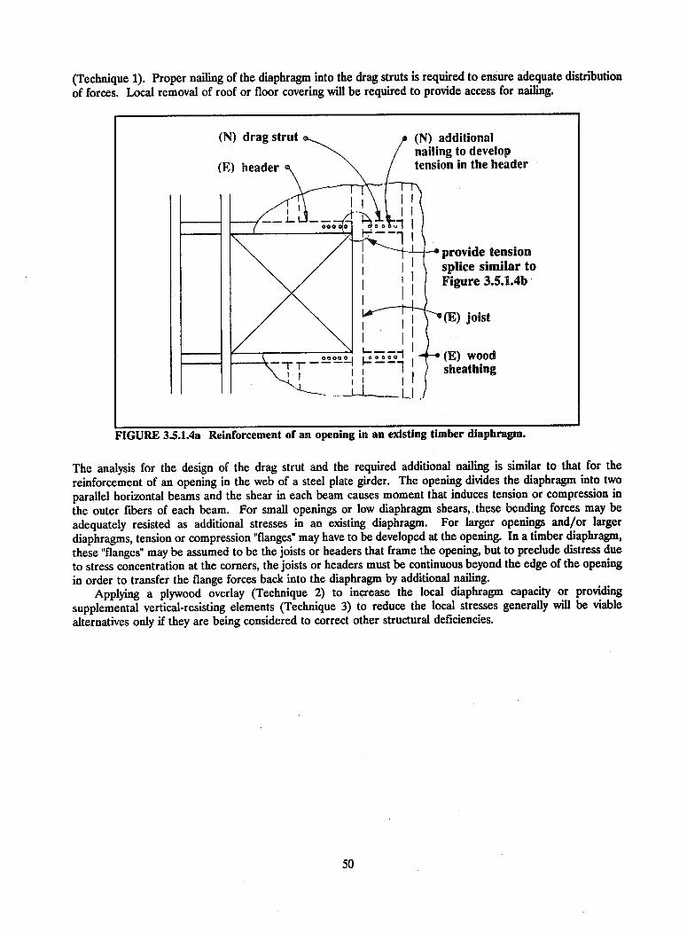
(Technique 1). Proper nailing of the diaphragm into the drag struts is required to ensure adequate distribution
of forces. Local removal of roof or floor covering will be required to provide access for nailing.
FIGURE 3.5.1.4a Reinforcement of an opening in an existing timber diaphragm.
The analysis for the design of the drag strut and the required additional nailing is similar to that for the
reinforcement of an opening in the web of a steel plate girder. The opening divides the diaphragm into two
parallel horizontal beams and the shear in each beam causes moment that induces tension or compression in
the outer fibers of each beam. For small openings or low diaphragm shears, these bending forces may be
adequately resisted as additional stresses in an existing diaphragm. For larger openings and/or larger
diaphragms, tension or compression "flanges" may have to be developed at the opening. In a timber diaphragm,
these "flanges" may be assumed to be the joists or headers that frame the opening, but to preclude distress due
to stress concentration at the corners, the joists or headers must be continuous beyond the edge of the openingin order to transfer the flange forces back into the diaphragm by additional nailing.
Applying a plywood overlay (Technique 2) to increase the local diaphragm capacity or providing
supplemental vertical-resisting elements (Technique 3) to reduce the local stresses generally will be viable
alternatives only if they are being considered to correct other structural deficiencies.
50
(N) dragstrut (N) additionalnailing to develop
(E) header tension in the header
000 0 - 1 I
\ / I j~ -provide tension\ / splice similar to
I igure 3.5.1.4b
_ < ; _ _ > ~~~~~(E) jroij3st14
(E) wood1, / sheathing
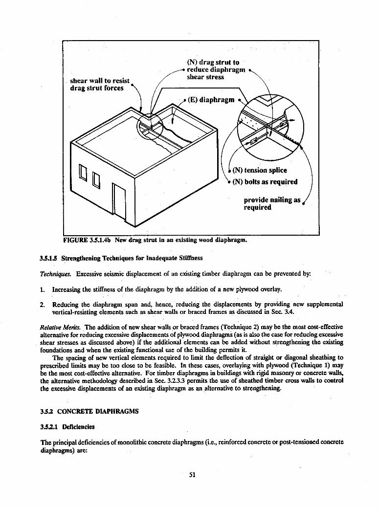
FIGURE 3.5.1.4b New drag strut in an existing wood diaphragm.
3.5.1.5 Strengthening Techniques for Inadequate Stiffness
Techniques. Excessive seismic displacement of an existing timber diaphragm can be prevented by:
1. Increasing the stiffness of the diaphragm by the addition of a new plywood overlay.
2. Reducing the diaphragm span and, hence, reducing the displacements by providing new supplementalvertical-resisting elements such as shear walls or braced frames as discussed in Sec. 3A.
Relative Merits. The addition of new shear walls or braced frames (Technique 2) may be the most cost-effectivealternative for reducing excessive displacements of plywood diaphragms (as is also the case for reducing excessiveshear stresses as discussed above) if the additional elements can be added without strengthening the existingfoundations and when the existing functional use of the building permits it.
The spacing of new vertical elements required to limit the deflection of straight or diagonal sheathing toprescribed limits may be too close to be feasible. In these cases, overlaying with plywood (Technique 1) maybe the most cost-effective alternative. For timber diaphragms in buildings with rigid masonry or concrete walls,the alternative methodology described in Sec. 3.2.3.3 permits the use of sheathed timber cross walls to controlthe excessive displacements of an existing diaphragm as an alternative to strengthening.
3.5.2 CONCRETE DIAPHRAGMS
3.5.2.1 Deficiencies
The principal deficiencies of monolithic concrete diaphragms (i.e., reinforced concrete or post-tensioned concretediaphragms) are:
51
(N) drag strut toreduce diaphragmshear stressshear wall to resist
drag strut forces
(N) bolts as required

e Inadequate in-plane shear capacity of the concrete diaphragm,
e Inadequate diaphragm chord capacity, and
o Excessive shear stresses at the diaphragm openings or plan irregularities.
3.5.2.2 Strengthening Techniques for Inadequate Shear Capacity
Techniques. Deficient in-plane shear capacity of monolithic concrete diaphragms can be improved by:
1. Increasing the shear capacity by overlaying the existing concrete diaphragm with a new reinforced concretetopping slab (Figure 3.5.2.2).
2. Reducing the shear in the existing concrete diaphragm by providing supplemental vertical-resisting elements(i.e., shear walls or braced frames) as discussed in Sec. 3.4.
Relative Merits. Con-crete diaphragms usu-ally are strengthenedwith a concrete over-
~ (E) wall lay. This will require
removal and replace-, (N) concrete chord reinforcement ment of the existing
partitions and floorfinishes and will be
(N) concrete topping disruptive to ongoingoperations even thoughthe work can be limit-
< clean and (E) concrete slab ed to one floor or a
., .F //~ roughen portion of a floor at a,_______________________________________ surface tim e. A dding the
concrete overlay also.-- will increase the dead3. .. . \weight of the structure;
therefore, existingmembers, connections,and foundations mustbe checked to ensure
(N) dowel that they are capableof resisting these add-ed loads.
/ / a' / It may be possible~"' ./. to avoid strengthening
a concrete diaphragmFIGURE 3.5.2.2 Strengthening an existing concrete diaphragm with a new topping by providing additionalslab and chord. shear walls or vertical
bracing that will re-duce the diaphragm shears. This alternative generally is more costly than the overlay, but it may be competitivewhen it can be restricted to the perimeter of the building and when minimal work is required on the foundations.For shear transfer, new reinforced concrete or masonry shear walls will require dowels grouted in holes drilledin the concrete diaphragms. When the concrete diaphragm is supported on steel framing, shear walls or vertical-bracing may be located under a supporting beam. Dowels or other connections for shear walls or bracing maybe welded to the steel beam, but it also may be necessary to provide additional shear studs, welded to the steel
52

beam, in holes drilled in the diaphragm slab to facilitate the shear transfer from the concrete slab to the steelbeam.
3.5.2.3 Strengthening Techniques for Inadequate Flexural Capacity
Techniques. Deficient flexural capacity in monolithic concrete diaphragms can be improved by
1. Increasing the flexural capacity by removing the edge of the diaphragm slab and casting a new chordmember integral with the slab (Figure 3.5.2.3).
2. Adding a new chord member by providing a new reinforced concrete or steel member above or below theslab and connecting the new member to the existing slab with drilled and grouted dowels or bolts asdiscussed in Sec. 3.5.4.3.
3. Reducing the existing flexural stresses by providing supplemental vertical-resisting elements (i.e., shear wallsor braced frames) as discussed in Sec. 3.4.
Relative Merits. If the existingconcrete slab is supported onsteel framing, the most cost-effective means of providing -, / /
sufficient diaphragm chord ca- // (N) concrete chordpacity is to ensure adequateshear transfer of the diaphragm ///(E) concrete slabto the perimeter steel beam byadding drilled and grouted bolts / / /and to ensure adequate / /strength and stiffness capacityof the perimeter beam connec-tions. If a new chord is beingsecured with drilled andgrouted anchors to an existingdiaphragm containing prestress- / /ing strands, drilling must be / (N) dowel to wall--may
done very carefully to ensure need (N) dowel in slab alsothat the strands are not cut. / after proper
Figure 3.5.2.3 shows the shoring, removeprovision of a new diaphragm existing concretechord and/or collector member slab, exposeas well as new dowels for wall reinforcement andanchorage or shear transfer cast new concretefrom the existing concrete dia-phragm. Because of the poten-tial risk of gravity load failure (E) wallat the interface with the existing FIGURE 3.5.23 Adding a new chord member to an existing concreteslab, this detail is recommended diaphragm (not recommended for precast elements).only for one-way slabs in thedirection parallel to the slab span. For other conditions, a detail using new concrete above or below the slabis recommended. Steel plates or shapes (as shown in Sec. 3.5.4.3) could be used with through bolts tightenedto transfer load by friction.
Providing new structural steel or reinforced concrete elements to reinforce the existing diaphragm at theopenings is similar to the analysis described in Sec. 3.5.1.4. The tensile or compressive stresses in the newelements at the opening must be developed by shear forces in the connection to the existing slab. The new ele-
53

meats also must be extended beyond the opening a sufficient distance to transfer the tensile or compressivechord forces back into the existing slab in the same manner. Removing the stress concentration by filling in theopening (Technique 3) may be a feasible alternative provided that the functional requirements for the opening(e.g., stair or elevator shaft or utility trunk) no longer exist or it has been relocated.
3.5.2A Strengthening Techniques for Excessive Shear Stresses at Openings
Techniques. Deficient shear stress at diaphragm openings or plan irregularities in monolithic concrete slabs canbe improved by:
1. Reducing the local stresses by distributing the forces along the diaphragm by means of structural steel(Figure 3.5.2.4a), or reinforced concrete elements cast beneath the slab and made integral through the useof drilled and grouted dowels.
FIGURE 3.S.2.4adiaphragm.
Reinforcement of an opening In an existing concrete
2. Increasing the capacity of the concrete by providing a new concrete topping slab in the vicinity of theopening and reinforcing with trim bars (Figure 3.5.2.4b).
54
(N) steel trim member
Section a-a
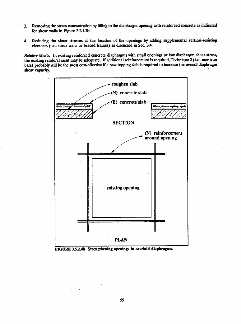
3. Removing the stress concentration by filling in the diaphragm opening with reinforced concrete as indicatedfor shear walls in Figure 3.2.1.2b.
4. Reducing the shear stresses at the location of the openings by adding supplemental vertical-resistingelements (i.e., shear walls or braced frames) as discussed in Sec. 3.4.
Relative Meits. In existing reinforced concrete diaphragms with small openings or low diaphragm shear stress,the existing reinforcement may be adequate. If additional reinforcement is required, Technique 2 (i.e., new trimbars) probably will be the most cost-effective if a new topping slab is required to increase the overall diaphragmshear capacity.
55
3.5.3 POURED GYPSUM DIAPHRAGMS
3.53.1 Deficiencies
Poured gypsum diaphragms may be reinforced or unreinforced and may have the same deficiencies as monolithicconcrete diaphragms (see Sec. 3.5.2.1.).
3.532 Strengthening Techniques for Poured Gypsum Diaphragms
Techniques. Strengthening techniques for deficiencies in poured gypsum diaphragms are similar to those listedfor concrete diaphragms (see Sec. 3.5.2.2, 3.5.2.3, and 3.5.2.4); however, the addition of a new horizontal bracingsystem may be the most effective strengthening alternative.
Relative Merits. Poured gypsum has physical properties similar to those of very weak concrete. Tables ofallowable structural properties (i.e., shear, bond, etc.) are published in various building codes and engineeringmanuals. A typical installation is for roof construction using steel joists. Steel bulb tees, welded or clipped tothe joists, span over several joists and support rigid board insulation on the tee flanges. Reinforced orunreinforced gypsum is poured on the insulation board to a depth of 2 or 3 inches, embedding the bulbed stemsof the tees. While use of the strengthening techniques discussed for reinforced concrete diaphragms (i.e.,reinforced overlays, additional chord reinforcement, etc.) is technically possible, application of these techniquesgenerally is not practical because of the additional weight or low allowable stresses of gypsum. Since dead loadsnormally constitute a significant portion of the design loads for roof framing members, the addition of severalinches of gypsum for a reinforced overlay probably will overstress the existing light steel framing. Similarly, thelow allowable stresses for dowels and bolts will allow strengthening of only marginally deficient diaphragms. Forthese reasons, gypsum diaphragms found to have significant deficiencies may have to be removed and replacedwith steel decking or may be strengthened with a new horizontal bracing system (see Figure 3.5.5.2b).
3.S.4 PRECAST CONCRETE DIAPHRAGMS
3.5A.1 Deficiencies
The principal deficiencies of precast or post-tensioned concrete planks, tees, or cored slabs are:
o Inadequate in-plane shear capacity of the connections between the adjacent units,
* Inadequate diaphragm chord capacity, and
* Excessive in-plane shear stresses at diaphragm openings or plan irregularities.
3.5A.2 Strengthening Techniques for Inadequate Connection Shear Capacity
Techniques. Deficient in-plane shear capacity of connections between adjacent precast concrete planks, tees, orcored slabs can be improved byr
1. Replacing and increasing the capacity of the existing connections by overlaying the existing diaphragm witha new reinforced concrete topping slab (Figure 3.5.4.2).
2. Reducing the shear forces on the diaphragm by providing supplemental vertical-resisting elements (i.e., shearwalls or braced frames) as discussed in Sec. 3.4.
56

Relative Merits. The capacity of an existing diaphragm composed of precast concrete elements (i.e., cored slabs,
tees, planks, etc.) generally is limited by the capacity of the field connections between the precast elements. Itmay be possible to modify these connections for a moderate increase in diaphragm capacity-, however, it usuallyis not feasible to develop the full shear capacity of the precast units except with an adequately doweled and
complete poured-in-place connection. This usually is very costly. Overlaying the existing precast system with
a new reinforced concrete topping (Technique 1) is an effective procedure for increasing the shear capacity of
the existing diaphragm. Because of the relatively low rigidity of the existing connections, the new topping shouldbe designed to resist the entire design shear. Existing floor diaphragms with precast concrete elements may havea 2- or 3-inch poured-in-place topping with mesh reinforcement to compensate for the irregularities in precast
elements. Applying an additional topping slab over the existing slab may be prohibitive because of the additionalgravity and seismic loads that must be resisted by the structure. Where mechanical connections between units
exist along with a topping slab, the topping slab generally will resist the entire load (until it fails) because of therelative rigidities; therefore, the addition of mechanical fasteners generally is ineffective. For the above reasons
the most cost-effective alternative may be reducing the diaphragm shear forces through the addition ofsupplemental shear walls or braced frames.
a concrete overlay.
57

35.4.3 Strengthening Techniques for Inadequate Chord Capacity
Techniques. Deficient diaphragm chord capacity of precast concrete planks, tees, or cored slabs can be improvedby.
1. Providing a new continuous steel member above or below the steel slab and connecting the new memberto the existing slab with bolts (Figure 3.5.4.3).
2. Removing the edge of the diaphragm and casting a new chord member integral with the slab (Figure3.5.2.3).
3. Reducing the diaphragm chord forces by providing supplemental vertical-resisting elements (i.e., shear wallsor braced frames) as discussed in Sec. 3.4.
FIGURE 3.5A.3 Adding a new steel member to an existing precast concretediaphragm.
Relative Merits. Providing a new steel chord member (Technique 1) generally is the most cost-effective approachto rehabilitating a deficient diaphragm chord for precast concrete elements. When this approach is used;adequate shear transfer between the existing planks or slabs and the new chord member must be provided.Grouting under the new steel chord member may be necessary to accommodate uneven surfaces. Althoughtypically more costly, casting a new chord into the diaphragm (Technique 2) may be considered a viable alterna-tive where the projection caused by a new steel chord member is unacceptable for architectural reasons. If Tech-nique 2 is considered, shoring of the planks or slabs will be necessary during construction. Technique 3 generallywould be viable only if it is being considered to improve other deficient conditions.
58

3.5.4.4 Strengthening Techniques for Excessive Shear Stresses at Openings
Deficient diaphragm shear capacity at diaphragm openings or plan irregularities can be improved by
1. Reducing the local stresses by distributing the forces along the diaphragm by means of concrete drag strutscast beneath the slab and made integral with the existing slab with drilled and grouted dowels.
2. Increasing the capacity by overlaying the existing slab with a new reinforced concrete topping slab withreinforcing trim bars in the vicinity of the opening (Figure 3.5.4.2).
3. Removing the stress concentration by filling in the diaphragm opening with reinforced concrete (Figure3.2.1.2b).
4. Reducing the shear stresses at the location of the openings by providing supplemental vertical-resisting
elements (i.e., shear walls or braced frames) as discussed in Sec. 3.4.
Relative Merits. The relative merits for rehabilitating excessive shear stresses at openings in precast concreteplanks, tees, or core slabs are similar to those discussed in Sec. 3.5.2.4 for cast-in-place concrete diaphragms.
3.5.5 STEEL DECK DIAPHRAGMS
3.5.5.1 Deficiencies
The principal deficiencies in steel deck diaphragms are inadequate in-plane shear capacity which may be
governed by the capacity of the welding to the supports or the capacity of the seam welds between the deck units,inadequate diaphragm chord capacity, and excessive in-plane shear stresses at diaphragm openings or plan
irregularities.
3.5.5.2 Strengthening Techniques for Inadequate Shear Capacity
Deficient in-plane shear capacity of steel deck diaphragms can be improved by:
1. Increasing the steel deck shear capacity by providing additional welding.
2. Increasing the deck shear capacity of unfilled steel decks by adding a reinforced concrete fill (Figure
3.5.5.2a) or overlaying with concrete filled steel decks a new topping slab.
3. Increasing the diaphragm shear capacity by providing a new horizontal steel bracing system under theexisting diaphragm (Figures 3.5.5.2b and 3.5.5.2d).
4. Reducing the diaphragm shear stresses by providing supplemental vertical-resisting elements to reduce thediaphragm span as discussed in Sec. 3.4.
Relative Mefits. Steel decking, with or without an insulation fill (e.g., vermiculite or perlite), may be used as a
diaphragm whose capacity is limited by the welding to the supporting steel framing and crimping or seam weldingof the longitudinal joints of the deck units. The shear capacity of this type of diaphragm may be increasedmodestly by additional welding (Technique 1) if the shear capacity of the existing welds is less than the allowableshear of the steel deck itself. Significant increases in capacity may be obtained by adding a reinforced concretefill (Technique 2) and shear studs welded to the steel framing through the decking. This procedure will require
the removal of any insulation fill and the removal and replacement of any partitions and floor or roof finishes.The shear capacity of steel deck diaphragms in open web joists often is limited by the lack of adequate con-
nection from deck to shear wall or other vertical element. The lack of intermediate connectors between joists
59

is common. Frequently, the joist bearing ends themselves are not well connected to transfer diaphragm shear.Addition of an edge support connected to wall and diaphragm often is feasible.
FIGURE 3.5.5.2a Strengthening an existing steel deck diaphragm.
The capacity of steel deck-ing with an existing reinforcedconcrete fill may be increasedby adding a reinforced concreteoverlay (Technique 2). Al-though this is an expedientalternative for increasing theshear capacity of an existingcomposite steel deck, providingadequate shear transfer to thevertical-resisting members orchord elements through theexisting composite decking mayrequire special details (e.g.,additional shear studs). Sincethe addition of a concrete over-lay will increase the deadweight of the structure, theexisting members, connections,and foundation must bechecked to determine whetherthey are capable of resisting theadded loads.
The above alternativesprovide positive, direct methodsfor strengthening an existingsteel deck diaphragm. Bothalternatives require completeaccess to the top of the dia-
phragm and the removal and replacement of partitions and floor finishes. Technique 2 (i.e., topping over anexisting concrete fill) will change the finished floor elevation by several inches and will therefore require anumber of nonstructural adjustments to the new elevation (e.g., to stairs, elevators, floor electrical outlets, etc.).
An additional alternative for strengthening steel decking without concrete fill is to add new horizontalbracing under the decking (Technique 3). Since steel decking generally is supported on structural steel framing,the existing framing with new diagonal members forms the horizontal bracing system. The diaphragm shearsare shared with the existing decking in proportion to the relative rigidity of the two systems. This alternativerequires access to the underside of the floor or roof framing and may require relocation of piping, ducts, orelectrical conduit as well as difficult and awkward connections to the existing framing. These costs must beweighed against the costs for a concrete overlay. It should be noted that this alternative may not be feasible forsteel decking with a composite concrete fill because of the much greater rigidity of the existing compositediaphragm compared with that of the bracing system. For the bracing system to be effective in this case, thediaphragm shears would be distributed on the basis of the bracing system and the steel decking without theconcrete fill (i.e., failure of the concrete fill in shear would be assumed to be acceptable). The new horizontalbracing system will require continuous chord or collector members (Figure 3.5.5.2d) to receive the bracing forcesand transfer them to shear walls or other vertical-resisting elements. In Figure 3.5.5.2d, a tubular steel memberis a preferred section for the new bracing members as is the tee section in Section a-a for the chord or collectormembers. Where existing construction does not permit the use of the tee section, an angle may be used asshown in Section b-b. In the latter case, bending of the angle and prying action on the anchor bolts may needto be investigated.
Reduction of the existing diaphragm stresses to acceptable levels by providing additional shear walls orvertical bracing (Technique 4) also may be a feasible alternative. The choice between shear walls or bracing willdepend on compatibility with the existing vertical-resisting elements (i.e., additional shear walls should beconsidered for an existing shear wall system and additional bracing for an existing bracing system). The
60
(N) reinforcement
(N) concrete fill,reinforce as required
(N) shear studs, asrequired, welded tobeam
(E) steel beam
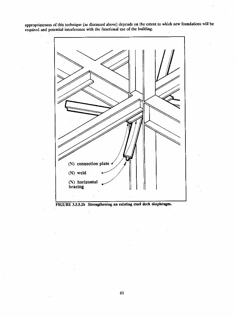
appropriateness of this technique (as discussed above) depends on the extent to which new foundations will be
required and potential interference with the functional use of the building.
FIGURE 3.5.5.2b Strengthening an existing steel deck diaphragm.
61
I
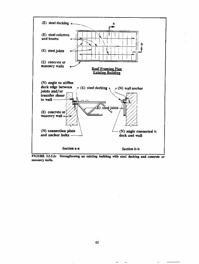
Eig uiild
(N) angle to stiffendeck edge betweenjoists and/ortransfer shearto wail t
masonry wall
(N) connection plateand anchor bolts -
Section a-a
I (E) steel decking (N) wall anchor
(N) angle connected tUdeck and wall
Section b-b
FIGURE
3.5.S.2c
Strengthening
an existing
building
with steel
decking
and concrete
or
FIGURE 3.5.5.c Strengthening an existing building with steel decking and concrete ormasonry walls.
62

(N) continuous chordor collector member .. a
(N) horizontal II I _| bbracing system L J
Roof Framing PlanRetrofitted Building
(N) continuous chordor collector bolted toexisting wall
a[ I
W (N)horionta bracing \_.welded to steel joistsand continuous member iat wall
Section a-a Section b-b
FIGURE 3S.5.2d Strengthening an existing building with steel decking andconcrete or masonry walls.
3.5.5.3 Strengthening Techniques for Inadequate Chord Capacity
Techniques. Deficient chord capacity of steel deck diaphragms can be improved by:
1. Increasing the chord capacity by providing welded or bolted continuity splices in the perimeter chord steelframing members.
2. Increasing the chord capacity by providing a new continuous steel member on top or bottom of thediaphragm (Figure 3.5.4.3).
3. Reducing the diaphragm chord stresses by providing supplemental vertical-resisting elements (i.e., shearwalls or braced frames) such that the diaphragm span is reduced as discussed in Sec. 3.4.
Relative Merits. Steel decking generally is constructed on steel framing. The perimeter members of the steelframing typically will have sufficient capacity to resist the diaphragm chord stresses provided the shear capacityof the connections between the decking and the chord member and the tensile capacity of the steel framingconnections are adequate to transfer the prescribed loads. Increasing the capacity of these connections by
63

providing additional plug welds to the decking or adding steel shear studs in the case of concrete-filled metaldecking may be required. Technique 1 generally is the most cost-effective.
Increasing the chord capacity by providing a new steel chord member to the perimeter of the diaphragm(Technique 2) would be appropriate only if it was impractical to use an existing member (Technique 1).
Reducing the diaphragm chord stresses by providing supplemental shear walls or braced frames (Technique3) generally would not be cost-effective to correct a chord capacity problem unless it is being seriously consideredto improve other component deficiencies as well.
3.5.5.4 Strengthening Techniques for Excessive Shear Stresses at Openings
Techniques. Excessive shear stresses at diaphragm openings or plan irregularities can be improved by:
1. Reducing the local stress concentrations by distributing the forces into the diaphragm by means of steel dragstruts.
2. Increasing the capacity of the diaphragm by reinforcing the edge of the opening with a steel angle framewelded to the decking.
3. Reducing the diaphragm stresses by providing supplemental vertical-resisting elements (i.e., shear walls,braced frames or new moment frames) such that the diaphragm span is reduced as discussed in Sec. 3.4.
Relative Merits. Openings and plan irregularities in steel deck diaphragms generally are supported along theperimeter by steel beams. If continuous past the corners of the openings or irregularities, these beams candistribute the concentrated stresses into the diaphragm provided the capacity of the connections between thedecking and the steel beams is adequate to transfer the prescribed loads. If inadequate, the connections can bereinforced by adding plug welds or shear studs.
If beams are not continuous beyond an opening or irregularity, new beams to act as drag struts can beprovided (Technique 1). Adequate connection of the beams to the diaphragm and to the existing beams will berequired to distribute loads.
Correcting the diaphragm deficiency by providing a steel frame around the perimeter of the opening or alongthe sides of the irregularity (Technique 2) is similar to providing drag struts. The connection between the newsteel members and the diaphragm must be sufficient to adequately distribute the local stresses into thediaphragm. The dimensions of the opening or irregularity will dictate whether this can be achieved solely withthe use of a perimeter steel frame.
Reducing the diaphragm stresses by providing supplemental shear walls or braced frames (Technique 3)generally would not be cost-effective to correct a diaphragm opening deficiency unless it also was beingconsidered to improve other component deficiencies.
3.5.6 HORIZONTAL STEEL BRACING
3.5.6.1 Deficiency
The principal deficiency in horizontal steel bracing systems is inadequate force capacity of the members (i.e.,bracing and floor or roof beams) and/or the connections.
3.5.6.2 Strengthening Techniques for Braces or Beams
Techniques. Deficient horizontal steel bracing system capacity can be improved by:
1. Increasing the capacity of the existing bracing members or removing and replacing them with new membersand connections of greater capacity.
64

2. Increasing the capacity of the existing members by reducing unbraced lengths.
3. Increasing the capacity of the bracing system by adding new horizontal bracing members to previouslyunbraced panels (if feasible).
4. Increasing the capacity of the bracing system by adding a steel deck diaphragm to the floor system abovethe steel bracing.
5. Reducing the stresses in the horizontal bracing system by providing supplemental vertical-resisting elements(i.e., shear walls or braced frames) as discussed in Sec. 3.4.
Relative Merits. Horizontal bracing systems to resist wind or earthquake forces have been in common use formany years in steel-framed industrial buildings. These bracing systems generally are integrated with the existingfloor or roof framing systems, and the capacity of the bracing system should be governed by the diagonal bracesand their connections. If the structural analysis indicates that the existing floor or roof framing members in thebracing systems do not have adequate capacity for the seismic loads, providing additional bracing or other lateral-load-resisting elements may be a cost-effective alternative to strengthening these members.
Simple strengthening techniques include increasing the capacity of the existing braces and their connections(e.g., single-angle bracing could be doubled, double-angle bracing could be "starred") as well as removing existingbraces and replacing them with stronger braces and connections (Technique 1). If the compressive capacity ofthe elements is the primary deficiency, providing a system of secondary braces that reduces the unbraced lengths(Technique 2) of the members may be cost-effective. The existing connections must be investigated and, if foundto be inadequate, the connections will need to be strengthened. Technique 3 (providing horizontal braces inadjacent unbraced panels if present) may be a very cost-effective approach to increasing the horizontal loadcapacity.
Existing horizontal bracing systems often do not have an effective floor diaphragm and new floor or roofdiaphragm consisting of a reinforced concrete slab or steel decking with or without concrete fill can be providedto augment or replace the horizontal bracing systems (Technique 4). A steel deck diaphragm may be designedto augment the horizontal bracing, but a concrete slab probably would make the bracing ineffective because ofthe large difference in rigidities. The concrete slab therefore would need to be designed to withstand the entirelateral load.
As with other diaphragms, it may be possible to reduce diaphragm stresses to acceptable limits by providingadditional shear walls or vertical bracing (Technique 5). However, unlike true diaphragm systems, a horizontalbracing system may not have the same shear capacity at any section (e.g., a simple bracing system between twoend walls may have increasing shear capacity from the center towards each end). In some cases, additionalvertical-resisting elements can increase the stresses in some of the elements of the existing bracing systems.
3.6 FOUNDATIONS
Deficient foundations occasionally are a cause for concern with respect to the seismic capacity of existingbuildings. Because the foundation loads associated with seismic forces are transitory and of very short duration,allowable soil stresses for these loads, combined with the normal gravity loads, may be permitted to approachultimate stress levels. Where preliminary analysis indicates that there may be significant foundation problems,recommendations from a qualified geotechnical engineer should be required to establish rational criteria for thefoundation analysis.
65

3.6.1 CONTINUOUS OR STRIP WALL FOOTINGS
3.6.1.1 Deficiencies
The principal deficiencies in the seismic capacity of existing continuous or strip wall footings are:
o Excessive soil bearing pressure due to overturning forces and
o Excessive uplift conditions due to overturning forces.
3.6.12 Strengthening Techniques for Excessive Soil Bearing Pressure
Techniques. The problem of excessive soil bearing pressure caused by seismic overturning forces can bemitigated by:
1. Increasing the bearing capacity of the footing by underpinning the footing ends and providing additionalfooting area (Figure 3.6.1.2a).
2. Increasing the vertical capacity of the footing by adding new drilled piers adjacent and connected to theexisting footing (Figure 3.6.1.2b).
3. Increasing the soil bearing capacity by modifying the existing soil properties.
4. Reducing the overturning forces by providing supplemental vertical-resisting elements (i.e., shear walls orbraced frames).
FIGURE 3.6.1.2a Underpinning an existing footing.
66
=* ":=. f Excavate underfooting and underpin
-'_: . . *- : . \ig in spaced increments
Drypack between Provide pocket in l I l i(E) and (N) footings new footing for .;
I after jacking _ 1 { jacking

FIGURE 3.6.1.2b Strengthening an existing wall footing by theaddition of drilled piers.
Relative Merits. The most effective procedure for correcting excessive soil pressure due to seismic overturningforces generally is to underpin the ends of the footing and to construct a larger footing under each end of theexisting footing (Technique 1). The new footing should be constructed in staggered increments, and each incre-ment should be preloaded by jacking prior to transfer of the load from the existing footing. An alternativeprocedure is to provide a drilled pier on each side and at each end of the wall (Technique 2). The reinforcedconcrete piers should be cast-in-place in uncased holes so as to develop both tension and compression. Eachpier should extend above the bottom of the footing and be connected by a reinforced concrete beam throughthe existing wall above the footing (Figure 3.6.1.2.b).
Techniques 1 and 2 are costly and disruptive. For this reason, when seismic upgrading results in increasedforces that require foundation strengthening, it may be cost-effective to consider other seismic upgradingschemes. Soil conditions may be such that modifying the capacity of existing soils is the most viable alternative.The soil beneath structures founded on clean sand can be strengthened through the injection of chemical grouts.The bearing capacity of other types of soils can be strengthened by compaction grouting. With chemical grout-ing, chemical grout is injected into clean sand in a regular pattern beneath the foundation. The grout mixes withthe sand to form a composite material with a significantly higher bearing capacity. With compaction grouting,grout also is injected in a regular pattern beneath the foundation but it displaces the soil away from the pocketsof injected grout rather than dispersing into the soil. The result of the soil displacement is a densification of thesoil and, hence, increased bearing capacity. Some disruption of existing floors adjacent to the subject foundationsmay be required in order to cut holes needed for uniform grout injection. Alternatively, seismic forces on thefooting can be reduced by adding other vertical-resisting elements such as bracing, shear walls, or buttresses.
67
(E) wall andstrip footing
(N) reinforcedconcrete needleIteam >>
(N) drilled concretepiers
3.6.1.3 Strengthening Techniques for Excessive Uplift Conditions
Techniques. Deficient capacity of existing foundations to resist prescribed uplift forces caused by seismic over-turning moments can be improved by:
1. Increasing the uplift capacity of the existing footing by adding drilled piers or soil anchors.
2. Increasing the size of the existing footing by underpinning to mobilize additional foundation and soil weight.
3. Reducing the uplift forces by providing supplemental vertical-resisting elements (i.e., shear walls or bracedframes) as discussed in Sec. 3.4.
Relative Merits. Any seismic rehabilitation alternative that requires significant foundation work will be costly.Access for heavy equipment (e.g., drilling rigs, backhoes, and pile drivers), ease of material handling, and theneed to minimize the disruption of the functional use of the building are a few of the reasons why exteriorfoundation rehabilitation work will be significantly less costly than interior work.
Providing a significant increase in the uplift capacity of an existing foundation generally is most effectivelyachieved by adding drilled piers or soil anchors (Technique 1). Reinforced concrete piers can be providedadjacent to the footing and connected to the existing footing with steel or concrete beams (Figure 3.6.1.2b).Locating the piers symmetrically on both sides of the footing will minimize connections that must transfereccentric loads. The details for eccentric connections may not always be feasible. However, providing concentricdrilled piers almost ensures that interior foundation work will be needed.
Soil anchors similar to those used to tie-back retaining walls also can be used instead of drilled piers.Hollow core drill bits from 6 inches to 2 feet in diameter can be used to drill the needed deep holes. Afterdrilling, a deformed steel tension rod is placed into the hole through the center of the bit. As the bit iswithdrawn, cement grout is pumped through the stem of the bit bonding to the tension rod and the soil. Thesetypes of soil anchors can provide a significant tensile capacity. Drilling rigs are available that can drill in theinterior of buildings even with low headroom; however, this is more costly.
Underpinning the ends of the footing to create a wider bearing area at each end has the beneficial effectof reducing the uplift by increasing the area, the moment of inertia, and the dead load of the existing footing.Although this may be a feasible alternative, it is usually less cost-effective than adding drilled piers or soilanchors. The size of the necessary footing addition becomes prohibitive if substantial uplift forces need to beresisted.
As with other rehabilitation techniques, reducing the overturning forces by providing additional vertical-resisting elements (Technique 3) such as braced frames, shear walls, or buttresses may be viable. The additionof buttresses may transfer loads to the exterior of the building where foundation work may not be so costly.
Some engineers believe that uplifting of the ends of rigid shear walls is not a deficiency and may actually
be beneficial in providing a limit to the seismic base shear. Others design the structure for the overturning forcesbut ignore the tendency of the foundation to uplift. If the foundations are permitted to uplift, the engineer mustinvestigate the redistribution of forces in the wall and in the soil due to the shift in the resultant of the soilpressure and also the potential distortion of structural and nonstructural elements framing into the wall.
3.6.2 INDIVIDUAL PIER OR COLUMN FOOTINGS
3.6.2.1 Deficiencies
The principal deficiencies in the seismic capacity of existing individual pier or column footings are:
* Excessive soil bearing pressure due to overturning forces,
o Excessive uplift conditions due to overturning forces, and
• Inadequate passive soil pressure to resist lateral loads.
68

3.62.2 Strengthening Techniques for Excessive Soil Bearing Pressure
Techniques. The problem of excessive soil bearing pressure due to overturning forces can be mitigated by:
1. Increasing the bearing capacity of the footing by underpinning the footing ends and/or providing additionalfooting area (Figure 3.6.1.2a).
2. Increasing the vertical capacity of the footing by adding new drilled piers adjacent and connected to theexisting footing (Figure 3.6.1.2b).
3. Reducing the bearing pressure on the existing footings by connecting adjacent footings with deep reinforcedconcrete tie beams.
4. Increasing the soil bearing capacity by modifying the existing soil properties.
5. Reducing the overturning forces by providing supplemental vertical-resisting elements (i.e., shear walls orbraced frames).
Relative Merits. The considerations in selecting alternatives to correcting excessive soil bearing pressure due tooverturning forces in individual pier or column footings are similar to those discussed above for continuous orstrip footings. There is, however, the additional alternative of tying adjacent footings together with a deepreinforced concrete beam (Technique 3), which may be a feasible means of distributing the forces resulting fromthe overturning moment to adjacent footings.
3.6.23 Strengthening Techniques for Excessive Uplift Conditions
Techniques. Deficient capacity of existing foundations to resist the prescribed uplift forces caused by seismicoverturning moments can be improved by:
1. Increasing the uplift capacity of the existing footing by adding drilled piers or soil anchors.
2. Increasing the size of the existing footing to mobilize additional foundation and soil weight.
3. Increasing the uplift capacity by providing a new deep reinforced concrete beam to mobilize the dead loadon an adjacent footing.
4. Reducing the uplift forces by providing supplemental vertical-resisting elements (i.e., shear walls or bracedframes).
Relative Merits. The considerations in selecting techniques to correct excessive uplift conditions due tooverturning forces in individual pier or column footings are similar to those discussed above for continuous orstrip footings. Technique 2 is appropriate only when, excessive uplift results from combined vertical loads andmoments on the footing. There is, however, the additional alternative of tying adjacent footings together witha deep reinforced concrete beam (Technique 3), which may be a feasible means for mobilizing the existing masssupported by an adjacent footing.
69

3.6.2A Strengthening Techniques for Inadequate Passive Soil Pressure
Techniques. The problem of excessive passive soil pressure caused by seismic loads can be mitigated by:
1. Providing an increase in bearing area by enlarging the footing.
2. Providing an increase in bearing area by adding new tie beams between existing footings.
3. Improving the existing soil conditions adjacent to the footing to increase the allowable passive pressure.
4. Reducing the bearing pressure at overstressed locations by providing supplemental vertical-resisting elements
such as shear walls or braced frames as discussed in Sec. 3.4.
Relative Mefits. As noted above, foundation rework generally is relatively costly. The foundation strengthening
technique that is the most cost-effective generally is the technique that can resolve more than one concern. The
addition of a new deep tie beam between adjacent footings if required to resist overturning forces will likely
address inadequate passive soil pressure concerns. As the above discussion indicates, the most cost-effective
alternative to the strengthening of an existing foundation usually is not readily apparent. Several alternative
schemes may have to be developed to the point where reasonable cost estimates can be made to evaluate the
tangible costs (i.e., the total actual work that needs to be accomplished) as well as the disruption or relocationof an ongoing function and the architectural considerations.
3.6.3 PILES OR DRILLED PIERS
3.63.1 Deficiencies
The principal deficiencies in the seismic capacity of piles or drilled piers are:
* Excessive tensile or compressive loads on the piles or piers due to the seismic forces combined with thegravity loads and
o Inadequate lateral force capacity to transfer the seismic shears from the pile caps and the piles to the soil.
3.63.2 Strengthening Techniques for Excessive Tensile or Compressive Loads
Techniques. Deficient tensile or compressive capacity of piles or piers can be improved by:
1. Increasing the capacity of the foundation by driving additional piles and replacing or enlarging the existingpile cap (Figure 3.6.3.2).
2. Reducing the loads on overstressed pile caps by adding tie beams to adjacent pile caps and distributing the
loads.
Relative Merits. Although it may be possible to drive additional piles to correct the deficiency, it usually is very
difficult to utilize the existing pile cap to distribute the loads effectively to both old and new piles. It then may
be necessary to consider temporary shoring of the column or other structural members supported by the pilecaps so that the pile caps can be removed and replaced with a new pile cap that will include the new piles.
As discussed above for individual footings, it may be more cost-effective to provide deep tie beams to
distribute some of the pile load to adjacent pile caps that may have excess capacity than to drive new piles.
70

(E) pile cap to bereplaced or enlarged
3.63.2 Upgrading an existing pile foundation.
3.633 Strengthening Techniques for Excessive Lateral Forces
Techniques. Deficient lateral force capacity of piles or piers can be improved by:
1. Reducing the loads on overstressed pile caps by adding tie beams to adjacent pile caps and distributing theloads.
2. Increasing the allowable passive pressure of the soil by improving the soil adjacent to the pile cap.
3. Increasing the capacity of the foundation by driving additional piles and replacing or enlarging existing pilecap.
4. Reducing loads on the piles or piers by providing supplemental vertical-resisting elements (i.e., bracedframes or shear walls) and transferring forces to other foundation members with reserve capacity asdiscussed in Sec. 3.4.
Relative Merits. The most cost-effective approach may be to provide tie beams between piers or pile caps(Technique 1). The tie beams will distribute loads between foundation elements as well as provide additionalsurface area to mobilize additional passive pressure. In specific situations, the other alternatives may be more
71

cost-effective depending upon accessibility as well as the impact each alternative may have on the ongoing
functional use of the building.
3.6.4 MAT FOUNDATIONS
3.6.4.1 Deficiencies
Seismic deficiencies in mat foundations are not common; however, the following two deficiencies can occur:
o Inadequate moment capacity to resist combined gravity plus seismic overturning forces and
* Inadequate passive soil pressure to resist sliding.
3.6.4.2 Strengthening Technique for Inadequate Moment Capacity
Deficient mat foundation moment capacity can be corrected by increasing the mat capacity locally by providing
additional reinforced concrete (i.e., an inverted column capital) doweled and bonded to the existing mat to act
as a monolithic section. If the inadequacy is due to concentrated seismic overturning loads, it may be possible
to provide new shear walls above the mat to distribute the overturning loads and also to locally increase thesection modulus of the mat.
3.6.43 Strengthening Technique for Inadequate Lateral Resistance
Deficient mat foundation lateral resistance (e.g., the possibility of a mat founded at shallow depth in the soil)
can be corrected by the construction of properly spaced shear keys at the mat perimeter. The shear keys would
be constructed by trenching under the mat, installing dowels on the underside of the mat, and placing reinforced
concrete in the trench.
3.7 DIAPHRAGM TO VERTICAL ELEMENT CONNECTIONS
Seismic inertial forces originate in all elements of buildings and are delivered through structural connections to
horizontal diaphragms. The diaphragms distribute these forces to vertical elements that transfer the forces to
the foundation.An adequate connection between the diaphragm and the vertical elements is essential to the satisfactory
performance of any structure. The connections must be capable of transferring the in-plane shear stress from
the diaphragms to the vertical elements and of providing support for out-of-plane forces on the vertical elements.
The following types of diaphragms are discussed below: timber, concrete, precast concrete, steel deck
without concrete fill, steel deck with concrete fill, and horizontal steel bracing.
3.7.1 CONNECTIONS IN TIMBER DIAPHRAGMS
3.7.1.1 Deficiencies
The principal connection deficiencies in timber diaphragms are:
Inadequate capacity to transfer in-plane shear at the connection of the diaphragm to interior shear walls or
vertical bracing,
72

* Inadequate capacity to transfer in-plane shear at the connection of the diaphragm to exterior shear wallsor vertical bracing, and
* Inadequate out-of-plane anchorage at the connection of the diaphragm to exterior concrete or masonry walls.
3.7.1.2 Strengthening Techniques for Interior Shear Wall Connections
Deficient shear transfer capacity of a diaphragm at the connection to an interior shear wall or braced frame canbe improved by:
1. Increasing the shear transfer capacity of the diaphragm local to the connection by providing additionalnailing to existing or new blocking (Figure 3.7.1.2a).
2. Reducing the local shear transfer stresses by distributing the forces from the diaphragm by providing acollector member to transfer the diaphragm forces to the shear wall (Figure 3.7.1.2b).
3. Reducing the shear transfer stress in the existing connection by providing supplemental vertical-resistingelements as discussed in Sec. 3.4.
(E) wood floor-E diaphragm
_ i _ . A .r 1
I I
l (N) framing anchorl l as an alternate
LX
,/1/
(E) floor joist /
(N) deep joist nailedto floor sheathingand top plate ofexisting shear wall(extend beyond wallas collector ifrequired)
(N) additional deepjoist if required
(E) plywoodsheathing
FIGURE 3.7.1.2a Strengthening the connection of a diaphragm to an interiorshear wall (wall parallel to floor joist).
73
il�1i! ii ,
-i
I
V
II
I
III
- -

Relative Merits. If the shear transfer deficiency is governed by the existing nailing, the most cost-effective alterna-
tive most likely is to provide additional nailing (Technique 1); however, stripping of the flooring or roofing
surface is required. If it is not feasible to provide adequate additional nailing within the length of the shear wall,
the installation of a collector (Technique 2) probably will be the most cost-effective alternative. As indicated
in the detail on the left of Figure 3.7.1.2b, if the nailing of the diaphragm to the new blocking is inadequate to
transfer the desired shear force over the length of the shear wall, a drag strut or collector member should be
provided and the new blocking extended as required beyond the end of the shear wall. The shear force is
collected in the drag strut and transferred to the shear wall with more effective nailing or bolting. The new
lumber must be dimensionally stable and cut to size.
Technique 3 (i.e., providing additional vertical-resisting elements) usually involves construction of additional
interior shear walls or exterior buttresses. This alternative generally is more expensive than the other two
because of the need for new foundations and for drag struts or other connections to collect the diaphragm shears
for transfer to the new shear walls or buttresses.
(N) deep blockingnailed to floorsheathing and dragstrut
extend blocking andrag strut beyondend of shear wall arequired to distrib'the force to the dia
W " , ~~
d
Is
uteiphragm
(N) deep blockingnailed to floorsheathing and topplate of existingshear wall
(N) blocking andanchor as alternato deep blocking
-I--~_-
:P
(N) drag strutnailed to top plate ofexisting shear wall
,0L.
FIGURE 3.7.1.2b Strengthening the connection of a diaphragm to an interior shear wall
(wall perpendicular to floor joist).
74
framingte
e5
1111
.
h1iT-~~~~~~~~~~~~

3.7.1.3 Strengthening Techniques for In-Plane Shear Transfer Capacity to Exterior Walls
Techniques. Deficient in-plane shear transfer capacity of a diaphragm to exterior shear walls or braced framescan be improved by.
1. Increasing the capacity of existing connections by providing additional nailing and/or bolting.
2. Reducing the local shear transfer stresses by distributing the forces from the diaphragm by providing chordsor collector members to collect and distribute shear from the diaphragm to the shear wall or bracing (Figure3.7.1.3).
3. Reducing the shear stress in the existing connection by providing supplemental vertical-resisting elementsas discussed in Sec. 3.4.
Relative Metis. Inadequate in-plane shear transfer capacity at an exterior shear wall typically is a deficiency whenlarge openings along the line of the wall exist. In this case, the shear force to be resisted per unit length of wallmay be significantly greater than the shear force per unit length transferred from the diaphragm by the existingnailing or bolting. If the diaphragm and the shear walls have adequate shear capacity (as described for interiorshear walls in Sec. 3.7.1.2), the solution requires transfer of the diaphragm shear to a collector member fordistribution to the discontinuous shear walls. For timber shear walls parallel to the joists, the exterior joistusually is doubled up at the exterior wall and extended as a header over openings. This doubled joist can bespliced for continuity and used as a drag strut with shear transfer to the wall by means of metal clip anchors andnails or lag screws. Figure 3.7;1.3 shows an elevation of an existing wood stud shear wall with a large opening.If the resulting unit shears in the walls on either side of the opening are larger than the existing shear transfercapacity of the roof diaphragm (e.g., in this case, the capacity is governed by the existing nailing to the perimeterblocking or double joists), a collector member is required to collect the diaphragm shears and transfer them, ata higher shear stress, to the shear walls. In Figure 3.7.1.3, it is assumed that additional capacity is required forthe existing shear walls and provided by new sheathing on the inside face. The assumed force path is from theroof sheathing to the blocking or double joists, from the blocking or joists to the exterior sheathing, from theexterior sheathing to the double plates at the top of the stud wall, and from the double plates to the collectormembers and the new sheathing. Adequate new or existing nailing must be provided at each of the aboveinterfaces. The shear walls also must be checked for shear transfer at the foundation and the need for hold-down provisions to resist uplift from the additional forces. Note that, in the detail parallel to the joists, theexisting double joists, if adequately spliced, can be utilized as a collector member. Similarly, if the existingdouble plates had been continuous over the opening, the collector member normal to the joists would not berequired.
For steel frame buildings with discontinuous braced panels, the spandrel supporting the floor or roof framingmay be used as a chord or collector member.
For discontinuous masonry, concrete or precast concrete shear walls parallel to the joists, the sheathingtypically is nailed to a joist or ledger bolted to the wall. The joist or ledger can be spliced for continuity andsupplementary bolting to the shear wall provided as required. For shear walls perpendicular to the joists, thesheathing may be nailed to discontinuous blocking between the ends of the joists. In this case, the chord orcollector member may have to be provided on top of the diaphragm. This new member may be a continuoussteel member bolted to the wall and nailed or lag screwed, with proper edge distance, to the diaphragm and alsocould be designed to provide out-of-plane anchorage as indicated in Figure 3.7.1.2b.
As discussed above with respect to interior wall connection deficiencies, providing additional vertical-resistingelements (Technique 3) is likely to be the most costly alternative unless it is being considered to correct othercomponent deficiencies.
75

(E) woodsheathing v (E) header beam r
(E) stud wall
Elevation
(E) joists androof sheathing
(E) woodsheathing 'N.
(E) double joists --if not lap-spliced,provide (N) collectormember as shown at left 4
(E)
(N) continous collectormember (splice by nailingto header beam)
Normal to Joists Parallel to Joists
Section a-a
FIGURE 3.7.13 Strengthening an existing wood stud shear wall with a large opening.
76

3.7.1.4 Strengthening Techniques for Inadequate Out-of-Plane Anchorage
Techniques. Deficient out-of-plane anchorage capacity of wood diaphragms connected to concrete or masonrywalls with wood ledgers can be improved by:
1. Increasing the capacity of the connection by providing steel straps connected to the wall (using drilled andgrouted bolts or through bolts for masonry walls) and bolted or lagged to the diaphragm or roof or floorjoists (Figures 3.7.1.4a, b, and c).
2. Increasing the capacity of the connections by providing a steel anchor to connect the roof or floor joists tothe walls (Figure 3.7.1.4d).
3. Increasing the redundancy of the connection by providing continuity ties into the diaphragm (Figure 3.7.1.4a-d).
Relative Merits. An important condition to be addressed in retrofitting any existing heavy walled structure witha wood diaphragm is the anchorage of the walls for out-of-plane forces. Prior to the mid-1970s, it was commonconstruction practice to bolt a 3x ledger to a concrete or masonry wall, install metal joist hangers to the ledger,drop in 2x joists, and sheath with plywood. The plywood that lapped the ledger would be nailed into the ledgerproviding both in-plane and out-of-plane shear transfer. The 1971 San Fernando earthquake caused many ofthese connections to fail. Out-of-plane forces stressed the ledgers in their weak cross-grain axis and caused manyof them to split, allowing the walls to fall out and the roof to fall in. When retrofitting a masonry or concretestructure, this condition should be remedied by providing a positive connection between the concrete or masonrywall and wood diaphragm. Techniques 1 and 2 are, in general, equally cost-effective. In addition to correctingthe ledger concerns, continuity ties need to be provided between diaphragm chords in order to distribute theanchorage forces well into the diaphragm. Joist hangers and glulam connections frequently have no tensilecapacity, but this tensile capacity can be provided by installing tie rods bolted to adjacent joist or glulam framing(Figure 3.7.1.4e). These continuity ties provide a necessary redundancy in the connection of heavy walledstructures to timber diaphragms.
FIGURE 3.7.1Aa Strengthening out-of-plane connections of a wood diaphragm.
77
-. (E) wall_- .- (E) floor or roof
(N) blocking/(E) joist
(N) metal strap anchor lagbolted to new blocking

out-of-plane connections of a wood dia-phragm.
778

FIGURE 3.7.1.4c Strengthening out-of-plane connections of a wooddiaphragm.
79
I--~ (E) wall- ~ *- (N) blocking
, A-- e (E) floor or roof
(E) joist(N) metal strap anchor(N) through rod

(N) anchorbolted to joist
(N) torque nut
FIGURE 3.7.1Ad Strengthening out-of-plane connections of a wooddiaphragm.
FIGURE 3.7.1.4e Strengthening tensile capacity of an existing
glulam beam connection.
80
(E) flooring
(E) glulamconnection
(E) glulam beam
(N) tie rodtension splice

3.7.15 Strengthening Techniques for Interfloor Tensile Capacity
Techniques. Deficient tensile capacity of the connections of wood stud shear walls through diaphragms can beimproved by.
1. Increasing the tensile capacity of the connections at the edge of the shear walls by providing metalconnectors.
2. Reducing the overturning moments by providing supplemental vertical-resisting elements as discussed in Sec.3.4.
81
FIGURE 3.7.L5a Strengthening the connection between shear walls using ametal strap.

FIGURE 3.7.1.5b Strengthening the connection between shear walls using a
hold-down.
Relative Merits. Typical wood stud framing has minimal capacity to transfer uplift forces from one shear wall
to the shear wall below. At exterior walls, plywood sheathing generally is provided with a horizontal joint below
the diaphragm to provide for "settling' shrinkage of the framing. Hence, minimal resistance to transfer uplift
forces is provided unless continuity in the sheathing is provided by nailing top and bottom pieces to a common
member (e.g., horizontal blocking or fascia as shown in Figure 3.5.1.3). The only resistance to uplift loads at
exterior or interior shear walls may be the withdrawal capacity of the nails.Metal straps or tie rods that tie the shear wall edge framing between floors (Figure 3.7.1.5c) are an eco-
nomical approach to providing the prescribed tensile capacity. The wall finishes would be removed, a hole drilled
or cut in the diaphragm or wall plates, and the connectors installed. Plywood shear walls should be adequately
edge nailed to the double studs that are connected with the metal straps. For light timber structures, the metal
straps may be of sheet metal and the sheathing can be nailed through the straps. When the straps are required
to be of greater thickness, they may be recessed and drilled for nailing of the sheathing or, alternatively, the
straps may be placed on the outside of the sheathing. See Figure 3.5.1.3 for typical splicing of sheathing and
development of double top plates as chord or collector members. Figures 3.7.1.5a and b present two connection
details where the shear wall on the upper floor does not align with the shear wall on a lower floor.
Technique 2 would be a viable alternative only if it is being considered to correct other component
deficiencies (e.g., inadequate shear capacity in the existing walls).
82
(N) steel angle(hold-down) thrubolted into (E or N)studs or 4X4 -
(N) steel rodhold-donwn bolted tosteel angle andanchor plate v
. I B y 7 boltdiameters
\I' (E) blocking
\~ (E) double top plate

(E or N) doublestud or 4X4(N) metal straphold-down(can be placed on topof existing sheathing)
(E) beam or header
(E) floor framing
(N) steel angle(hold-down) thrubolted into (E or N)studs or 4X4 -
(N) steel rodhold-down bolted tosteel angle andanchor plate
(E) beam or header
83
FIGURE 3.7.1.Sc Strengthening shear wall uplift capacity at a discontinuity.

3.7.2 CONNECTIONS OF CONCRETE DIAPHRAGMS
3.7.2.1 Deficiencies
The principal deficiencies of the connections of concrete diaphragms to vertical-resisting elements such as shearwalls or braced frames are:
* Inadequate in-plane shear transfer capacity and
* Inadequate anchorage capacity for out-of-plane forces in the connecting walls.
3.7.2.2 Strengthening Techniques for In-Plane Shear Wall Connections
Techniques. Deficient in-plane shear transfer capacity of a diaphragm to an interior shear wall or braced framecan be improved by:
1. Reducing the local stresses at the diaphragm-to-wall interface by providing collector members or drag strutsunder the diaphragm and connecting them to the diaphragm and the wall.
2. Increasing the capacity of the existing diaphragm-to-wall connection by providing additional dowels groutedinto drilled holes.
3. Reducing the shear stresses in the existing connection by providing supplemental vertical-resisting elementsas discussed in Sec. 3.4.
Relative Merits. Inadequate in-plane shear capacity of connections between concrete diaphragms and vertical-resisting elements usually occurs where large openings in the diaphragm exist adjacent to the shear wall (e.g.,at stair wells) or where the shear force distributed to interior shear walls or braced frames exceeds the capacityof the connection to the diaphragm. If the walls and the diaphragm have sufficient capacity to resist theprescribed loads, the most cost-effective alternative to increase the connection capacity is likely to be providingadditional dowels grouted into drilled holes (Technique 2). If the required connection capacity cannot bedeveloped within the length of the shear wall, the addition of collector members (Technique 1) as indicated inFigure 3.7.2.2 is likely to be the most cost-effective alternative.
As previously discussed, reducing the forces in the deficient connection by providing supplemental vertical-resisting elements (Technique 3) is not likely to be the most cost-effective alternative (due to the probable needfor new foundations and drag struts) unless it is being considered to correct other component deficiencies.
84

FIGURE 3.7.2.2 Use of a collector member to improve shear transfer from a concretediaphragm.
3.723 Strengthening Techniques for Out-of-Plane Capacity
Techniques. Deficient out-of-plane anchorage capacity of connections of concrete diaphragms to concrete ormasonry walls can be improved using one or both of the following techniques:
1. Increasing the capacity of the connection by providing additional dowels grouted into drilled holes.
2. Increasing the capacity of the connection by providing a new member above or below the slab connectedto the slab with drilled and grouted bolts similar to that indicated in Figure 3.5.4.3 for providing a newdiaphragm chord.
Relative Merits. The most cost-effective alternative generally is to provide additional dowels grouted into drilledholes (Technique 1). The holes are most efficiently drilled from the exterior through the wall and into the slab.Access to the exterior face of the wall is obviously required. When the exterior face is not accessible (e.g., whenit abuts an adjacent building), providing a new member connected to the existing wall and slab (Technique 2)is likely to be preferred.
85
(E) reinforced Ad (N) steel collectorconcrete shearwalls member
(E) reinforced _concrete slab
(N) collector member with(E) reinforced through bolts in drilledconcrete slabs holes; also could use
A ~ ~ /~reinforced concrete member/ 7' / ' "' with grouted dowels
/ =
c tNote: Bolts to slab are designed in(E) reinforced accordance with shear capacityconcrete shear slab and to wall in accordance withwall wall shear capacity. Consider
possible unequal loading of bolts."__vsan

3.7.3 CONNECTIONS OF POURED GYPSUM DIAPHRAGMS
3.7.3.1 Deficiencies
The principal deficiencies of poured gypsum diaphragms are similar to those for concrete diaphragms:
• Inadequate in-plane shear transfer capacity and
e Inadequate anchorage capacity for out-of-plane forces in the connecting walls.
3.73.2 Strengthening Techniques
Techniques. If the gypsum diaphragm is in direct contact with the shear wall, it will be possible to improve thein-plane shear transfer by providing new dowels from the diaphragm into the shear wall similar to the detailsindicated in Figures 3.5.2.2 and 3.5.2.3. Alternative strengthening techniques for the deficiencies also includeremoval of the gypsum diaphragm and replacement with steel decking or the addition of a new horizontal bracingsystem designed to resist all of the seismic forces.
Relative Merits. As indicated in Sec. 3.5.3.2, allowable structural stresses for gypsum are very low and theadditional strengthening that can be achieved is very limited. Further, the typical framing details (e.g., steel joist,bulb tee, and insulation board) are such that it is difficult to make direct and effective connections to the gypsumslab. For these reasons, the techniques involving removal and replacement or a new horizontal bracing systemare likely to be the most cost-effective solutions except when the existing diaphragm is only marginally deficient.
3.7A CONNECTIONS OF PRECAST CONCRETE DIAPHRAGMS
3.7.4.1 Deficiencies
The principal deficiencies of the connections of precast concrete diaphragms to the vertical-resisting elementsare:
* Inadequate in-plane shear transfer capacity and
* Inadequate anchorage capacity at the exterior walls for out-of-plane forces.
3.7.42 Strengthening Techniques for Precast Concrete Diaphragm Connections
Techniques. Deficient shear transfer or anchorage capacity of a connection of a precast concrete diaphragm toa concrete or masonry wall or a steel frame can be improved by.
1. Increasing the capacity of the connection by providing additional welded inserts or dowels placed in drilledor grouted holes.
2. Increasing the capacity of the connection by providing a reinforced concrete overlay that is bonded to theprecast units and anchored to the wall with additional dowels placed in drilled and grouted holes (Figure3.5.2.2).
3. Reducing the forces at the connection by providing supplemental vertical-resisting elements as discussed inSec. 3.4.
86
Relative Merits. Precast concrete plank or tee floors that have inadequate connection capacity for transferringin-plane shear to vertical elements such as shear walls or braced frames can be strengthened by drillingintermittent holes in the precast units at the vertical element. When the floors are supported on steel framing,welded inserts (or studs) can be added and the holes grouted (Technique 1). When the floors are supportedon concrete or masonry units, dowels can be inserted and grouted into the drilled holes. If the diaphragmcontains prestressing strands, extreme care must be taken prior to drilling to avoid cutting the strands. A morecostly alternative is to provide a reinforced concrete overlay that is bonded to the precast units and additionaldowels grouted into holes drilled into the wall (Technique 2). This will require the stripping of the existing floorsurface and raising the floor level by 2 to 3 inches, which will necessitate adjusting of nonstructural elements tothe new floor elevation (e.g., stairs, doors, electrical outlets, etc.).
As previously discussed, reducing the shear forces in the deficient connection by providing supplementalvertical-resisting elements (Technique 3) is not likely to be the most cost-effective alternative (due to theprobable need of new foundations and drag struts) unless it is being considered to correct other componentdeficiencies. This. alternative also is not effective in reducing the out-of-plane forces unless the new vertical-resisting elements can be constructed so as to form effective buttresses for the existing walls.
3.7.5 CONNECTIONS OF STEEL DECK DIAPHRAGMS WITHOUT CONCRETE FILL
3.7.5.1 Deficiencies
For steel deck diaphragms without concrete fill, the principal deficiencies of their connections to the vertical-resisting elements such as shear walls, braced frames, or moment frames are:
* Inadequate in-plane shear capacity and
* Inadequate anchorage capacity for out-of-plane forces in walls.
3.7.52 Strengthening Techniques for Steel Deck Connections
Techniques. Deficient shear transfer or anchorage capacity of a connection of a steel deck diaphragm to a shearwall, braced frame, or moment frame can be improved by:
1. Increasing the capacity of the connection by providing additional welding at the vertical element.
2. Increasing the capacity of the connection by providing additional anchor bolts.
3. Increasing the capacity of the connection by providing concrete fill over the deck with dowels grouted intoholes drilled into the wall.
4. Increasing the capacity of the connection by providing new steel members (Figure 3.7.5.2a) to effect a directtransfer of diaphragm shears to a shear wall.
5. Reducing the local stresses by providing additional vertical-resisting elements such as shear walls, bracedframes, or moment frames as discussed in Sec. 3.4.
Relative Merits. Steel decking typically is supported by metal framing, by steel angle, or by channel ledgers boltedto concrete or masonry walls. If the deficiency is in the connection and not the diaphragm, the most cost-effective alternative is to increase the welding of the decking to the steel member or ledger to at least thecapacity of the diaphragm. If supported by a ledger, the capacity of the ledger connections to the concrete ormasonry wall also may have to be improved; this is most effectively done by providing additional bolts in drilledand grouted holes.
87

(E) steel deckdiaphragm
- (E) open websteel joists
,'.-~- J'
(E) concrete ormasonry wall
(N) bent steel platesbetween joists, weldto steel deck
(N) continuous chord orcollector spliced bybolts to bend plates andanchored to masonry wall
(a)
(a (N) steel strap weldedto decking and new angle
(E) concreteor masonry wall <
(E) ledger angleand bolting
(N) bolts groutedin drilled holes o
(E) steel deck withreinforced concretefill by
(N) provide additionalwelding at deck to ledgerangle as required
(N) steel angle as requiredwelded to (E) ledger angle
(b)
FIGURE 3.7.5.2 Strengthening the connection of a steel deck diaphragm to aconcrete or masonry wall.
88
/

If the decking is being reinforced by filling with reinforced concrete, the most effective alternative will beto drill and grout dowels into the adjacent concrete or masonry wall and lap with reinforcing steel in the newslab. In some cases it may be feasible to use the existing steel support member at the wall as a collector asshown in Figure 3.7.5.2b. In this figure the capacity of the existing decking has been increased by additionalwelding to the ledger angle and the addition of a reinforced concrete fill. Reinforcement dowels are welded tothe angle that functions as a collector member and the shear forces are transferred to the wall by the existingand new anchor bolts, as required.
Steel deck roof diaphragms may be supported on open web steel joists that rest on steel bearing plates atthe top of concrete or masonry walls. In existing buildings that have not been properly designed for resistinglateral loads, there may not be a direct path for the transfer of diaphragm shears to the vertical walls, particularlywhen the decking span is parallel to the wall. As shown in Figure 3.7.5.2a, new steel elements (i.e., bent plates)can be provided between the joists for direct connection to the decking. A continuous member also can beprovided to function as a chord or collector member. As noted above, strengthening a steel deck diaphragmconnection to the vertical-resisting elements is effective only if the body of the diaphragm has adequate capacityto resist the design lateral forces. If the diaphragm does not have adequate capacity it needs to be strengthenedas discussed in Sec. 3.5.5.
As previously discussed, reducing the shear transfer forces in the deficient connection by providingsupplemental vertical-resisting elements (Technique 4) is not likely to be the most cost-effective alternative (dueto the probable need of new foundations and drag struts) unless it is being considered to correct othercomponent deficiencies. Further, in order to reduce out-of-plane wall forces, the new vertical elements wouldbe required to act as buttresses to the existing walls.
3.7.6 CONNECTIONS OF STEEL DECK DIAPHRAGMS WITH CONCRETE FILL
3.7.6.1 Deficiency
The principal deficiency of a connection of a steel deck diaphragm with concrete fill to the vertical-resistingelements such as shear walls, braced frames, or moment frames is the in-plane shear capacity or anchoragecapacity for out-of-plane forces in walls.
3.7.6.2 Strengthening Techniques for Steel Deck Connections
Techniques. Deficient shear capacity or anchorage of a connection of a steel deck diaphragm to a shear wall,braced frame, or moment frame can be improved by:
1. Increasing the shear capacity by drilling holes through the concrete fill, and providing additional shear studswelded to the vertical elements through the decking (Figure 3.5.5.2a).
2. Increasing the capacity of the connection by providing additional anchor bolts (drilled and grouted)connecting the steel support to the wall.
3. Increasing the capacity of the connection by placing dowels between the existing wall and diaphragm slab.
4. Reducing the local stresses by providing additional vertical-resisting elements such as shear walls, bracedframes, or moment frames as discussed in Sec. 3.4.
Relative Merits. If the deficiency is in both the connection of the diaphragm to the ledger and the ledger to theshear wall, the most cost-effective alternative may be to provide a direct force transfer from the slab to the wallby installing dowels (Technique 3). This is accomplished by removing the concrete to expose the diaphragm slabreinforcement, drilling holes in the wall, laying in dowels, and grouting and reconstructing the diaphragm slab.If the deficiency is in the slab-to-supporting steel member connection, Technique 1 is preferred. If the deficiencyis in the steel ledger to the wall connection, Technique 2 is preferred. Figure 3.7.5.2b illustrates a technique for
89

strengthening a steel deck diaphragm connection to a concrete or masonry wall. In this figure, it is assumed thatthe existing decking with concrete fill has adequate capacity for the design loads, but the connection to the wallis deficient for in-plane shear and out-of-plane anchorage forces. In the figure, the in-plane shear is assumedto be transferred from the decking to the existing ledger angle with additional welding (if required). The newangles, bolted to the wall and welded to the ledger angle, provide the necessary additional shear transfer capacity.The new steel straps, welded to the new angles and to the underside of the decking, provide the additional out-of-plane anchorage capacity. When the new dowels or anchor bolts are to be attached to existing thin concretewalls (e.g., precast tees or other thin ribbed concrete sections), through bolts or threaded rods are required toprovide adequate anchorage or doweling to the diaphragm. If the vertical-resisting elements are steel bracedframes or steel moment frames, the increase in connection capacity obviously would be achieved throughadditional welding and supplemental reinforcing members as required.
As previously discussed, reducing the forces in the deficient connection by providing supplemental vertical-resisting elements (Technique 4) is unlikely to be the most cost-effective alternative (due to the probable needof new foundations and drag struts) unless it is being considered to correct other component deficiencies.Further, in order to reduce out-of-plane wall forces, the new vertical elements would be required to act asbuttresses to the existing walls.
3.7.7 CONNECTIONS OF HORIZONTAL STEEL BRACING
3.7.7.1 Deficiencies
The two primary deficiencies in the connection capacity of horizontal steel braces to vertical-resisting elementssuch as shear walls or braced frames are:
• Inadequate in-plane shear transfer capacity and
* Inadequate anchorage capacity when supporting concrete or masonry wails for out-of-plane forces.
3.7.7.2 Strengthening Techniques for In-Plane Shear Transfer Capacity
Techniques. Deficient shear transfer capacity of connections of horizontal steel bracing systems to shear wallsor braced frames can be improved by.
1. Increasing the capacity by providing larger or more bolts or by welding.
2. Reducing the stresses by providing supplemental vertical-resisting elements such as shear walls or bracedframes as discussed in Sec. 3.4.
Relative Merits. The first alternative of providing larger or more bolts between the horizontal brace membersand the concrete or masonry shear wall or providing additional welding when connecting to a steel braced framegenerally will be the most cost-effective. Collectors along the wall may be required to distribute the concentratedbrace shear along the wall to allow for adequate bolt spacing.
As previously discussed, reducing the forces in the deficient connection by providing supplemental vertical-resisting elements (Technique 2) is not likely to be the most cost-effective alternative unless it is being consideredto correct other component deficiencies.
90

3.7.7.3 Strengthening Technique for Out-Of-Plane Anchorage
Technique. Deficient out-of-plane anchorage capacity of connections between horizontal steel bracing systems
and concrete or masonry shear walls can be improved by increasing the capacity of the connection by providingadditional anchor bolts grouted in drilled holes and by providing more bolts or welding to the bracing members.
3.8 VERTICAL ELEMENT TO FOUNDATION CONNECTIONS
Seismic inertial forces originate in all elements of buildings and are delivered through structural connections tohorizontal diaphragms. The diaphragms distribute these forces to vertical elements that transfer the forces to
the foundation and the foundation transfers the forces into the ground.An adequate connection between the vertical elements and the foundation is essential to the satisfactory
performance of a strengthened structure. The connections must be capable of transferring the in-plane lateralinertia forces from the vertical elements to the foundations and of providing adequate capacity for resisting upliftforces caused by overturning moments.
3.8.1 CONNECTIONS OF WOOD STUD SHEAR WALLS
3.8.1.1 Deficiencies
The principal deficiencies in the connection of wood stud shear walls to their foundations are:
* Inadequate shear capacity of the anchorage,
* Inadequate shear capacity of cripple stud walls, and
* Inadequate uplift capacity.
3.8.1.2 Strengthening Techniques for Inadequate Anchorage Shear Capacity
Techniques. Deficient shear capacity of the connection of a wood stud wall to its foundation can be improvedusing one or both of the following alternatives:
1. Increasing the shear capacity by providing new or additional anchor bolts between the sill plate and the
foundation (Figure 3.8.1.2a).
2. Increasing the shear capacity by providing steel angles or plates with anchor bolts connecting them to the
foundation and bolts or lag screws connecting them to the sill plate or wall (Figure 3.8.1.2b).
Relative Ments. Lack of adequate anchorage of the walls to the foundation can cause poor seismic performanceof wood frame structures. Although most older wood frame structures were not designed for seismic loads, theyhave performed extremely well in past earthquakes provided they were bolted to their foundation. This goodperformance may be attributed to their light weight, ductile connections, and redundant load paths provided theyare bolted to the foundations.
If the walls are not bolted to the foundation it is relatively simple to provide adequate anchorage. Providingbolts through the sill plates in the foundation (Technique 1) is typically the best approach. If a crawl space
exists, the bolts can be installed easily at regular intervals. If the walls sit directly on the foundation without floor
joists (e.g., a slab on grade), access through the wall covering (e.g., gypsum board) is required and the wall
surface subsequently must be patched. If the crawl space is not deep enough for vertical holes to be drilledthrough the sill plate, the addition of connection plates or angles (Technique 2) may be a more viable alternative.
91

I .' *l ' I l -
Providing wall to foundation anchors.
92

3.8.1.3 Strengthening Techniques for Cripple Stud Walls
Techniques. Weak cripple stud walls also are a significant reason for damage to wood frame structures. Cripple
stud perimeter walls are a frequent construction technique used to support the first floor of a wood structure
a short distance above the ground on sloping sites or to provide a crawl space under the floor framing. Theexterior face may be finished with wood or metal siding or plaster while the studs on the inside usually remainexposed.
Strengthening of the cripple stud walls is relatively simple. Plywood sheathing is nailed to the cripple studs
(usually on the inside). The top edge of the plywood is nailed into the floor framing and the bottom edge is
nailed into the sill plate (Figure 3.8.1.3). The sill plate also must be anchored to the foundation.
93

FIGURE 3.8.1.3 Strengthening a cripple stud wall.
3.8.1A Strengthening Techniques for Uplift Capacity
Deficient uplift capacity of the connections of wood shear walls to their foundations can be improved by:
1. Increasing the capacity by providing steel hold-downs bolted to the wall and anchored to the concrete(Figure 3.8.1.4).
2. Reducing the uplift requirement by providing supplemental shear walls (as discussed in Sec. 3.4.).
94
floor sheathingnailed to blocking(N) blocking nailedto top plate
(E) cripple wall stud
(N) plywoodsheathing
(N) vent holes
plywood nailed tonew blocking ifexisting sill is widerthan studF * | ~~~~~~(E) sill(N) concrete sill
6 2 ~~~~ anchor
, X-L l : 4 ( 2 1 1, (N) blocking nailed= I I T I _ j 1=<= ~~to existing sill
lllT~hI I '1(I hr{-1-
I

FIGURE 3.8.1.4 Strengthening the uplift capacity of wall to foundationconnection.
3.8.2 CONNECTIONS OF METAL STUD SHEAR WALLS
The connections of metal stud walls to the foundations can be strengthened in the same way as discussed abovefor wood stud walls (e.g., by adding welding, bolting, and screws where appropriate).
3.8.3 CONNECTIONS OF PRECAST CONCRETE SHEAR WALLS
3.83.1 Deficiencies
The principal deficiencies of the connections of precast concrete shear walls to the foundation are:
* Inadequate capacity to resist in-plane or out-of-plane shear forces and
* Inadequate hold-down capacity to resist seismic overturning forces.
95
(E) stud
(E) plywoodsheathing
(N) metalhold-down
(N) lag bolt or thrubolt
(N) expansionanchor tofoundation \(E) mud sill a\ j
(N) expansion sillanchor

3..3.2 Strengthening Techniques for Shear Capacity
Techniques. Deficient shear capacity of the connections of precast concrete shear walls to the foundation canbe improved by-
1. Increasing the capacity of the connection by providing a new steel member connecting the wall to thefoundation or the ground floor slab (Figure 3.8.3.2).
2. Increasing the capacity of the connection by adding a new thickness of concrete (either cast-in-place orshotcrete) placed against the precast wall doweling into the existing foundation or ground floor slab.
10__/ (N) steel an
(N) anchor
(E) foundal
(E) precastconcrete wall
- 11 . glgie
ion slab
f- -- - -_
, 3,
I i
C |I | I jff ! 1 'F7-7_-i 151W I } >
_~~~~~~~~~~~~~~~~) I -I -:1-_
Li I In_ I rS
I.
.j . -0 'a
o3 I
[I
-- 0.e
.,, ,'1 sLA ° s . j I6 L I , , , . * . .. . . a
FIGURE 3.83.2 Strengthening of a precast concrete wall to foundationconnection.
Relative Merits. Early precastconcrete wall construction fre-quently had minimal lateralconnection capacity at the foun-dation. These connectionsusually can be strengthenedmost economically by attachinga steel member to the wall andthe floor slab or foundationwith drilled and grouted an-chors or expansion bolts (Tech-nique 1). Care must be takento place bolts and/or dowels asufficient distance away fromconcrete edges to prevent spall-ing under load. A more costlyalternative involves thickeningthe precast wall with a mini-mum of 4 inches of new rein-forced concrete, either cast-in-place or shotcrete. The newconcrete must be anchored tothe precast wall and must ex-tend above the base of the wallhigh enough to develop newdowels drilled into the founda-tion. The existing foundationthen must be checked for theadditional load.
3.833 Strengthening Techniques for Hold-down Capacity
Techniques. Deficient hold-down capacity of the connections of precast concrete shear walls to the foundationcan be improved by:
1. Increase the hold-down capacity by removing concrete at the edge of the precast unit to expose the rein-forcement, provide new drilled and grouted dowels into the foundation, and pour a new concrete pilaster.
2. Reduce the uplift forces by providing supplemental vertical-resisting elements such as shear walls or bracedframes as discussed in Sec. 3.4.
96
. 1
, . I . I
I

Relative Merits. Deficient hold-down capacity of precast units usually will occur when one unit or a part of oneunit is required to resist a significant share of the seismic load. If the wall has sufficient bending and shearcapacity, then increasing the hold-down capacity using Technique 1 is usually the most cost-effective. When awall is comprised of a number of solid (i.e., nd significant openings) precast panels, the overturning forcesgenerally will be minimal provided there is adequate vertical shear capacity in the connection between the edgesof adjacent panels. In this case, the connections must be checked and, if necessary, strengthened as describedin Sec. 3.2.2.
Technique 2 usually is a viable approach only if it is being considered to correct other componentdeficiencies. When excessive uplift forces are due to inadequate vertical shear capacity in the vertical connectionsbetween adjacent precast units, strengthening of those connections (see Sec. 3.2.2) will reduce the uplift forces.
3.8A CONNECTION OF BRACED FRAMES
3.8A.1 Deficiencies
The principal deficiencies of the connections of steel braced frames to the foundation are:
* Inadequate shear capacity and
* Inadequate uplift resistance.
3.8A.2 Strengthening Techniques for Shear Capacity
Techniques. Deficient shear capacity of the connections of steel braced frames to the foundations can beimproved by:
1. Increasing the capacity by providing new steel members welded to the braced frame base plates andanchored to the slab or foundation with drilled and grouted anchor bolts.
2. Reducing the shear loads by providing supplemental steel braced frames as discussed in Sec. 3.4.
Relative Merits. The first alternative generally will be the most cost-effective provided the existing slab orfoundation can adequately resist the prescribed shear. Steel collectors welded to the existing steel base platesmay be necessary to distribute the shear forces into the slab or foundation. If the existing foundation requiresstrengthening to provide adequate shear capacity, determining the most cost-effective alternative requirescomparing the effort necessary to construct a reinforced concrete foundation to the effort and disruption offunctional space required to install supplementary shear walls and their associated foundations and collectors.
3.8.43 Strengthening Techniques for Uplift Resistance
Techniques. Deficient uplift resistance capacity of the connections of steel braced frames to the foundations canbe improved by:
1. Increasing the capacity by providing new steel members welded to the base plate and anchored to theexisting foundation.
2. Reducing the uplift loads by providing supplemental steel braced frames as discussed in Sec. 3.4.
Relative Merits. Inadequate uplift resistance capacity of a steel braced frame seldom results just because ofdeficient connection to the foundation but is typically a concern reflecting the uplift capacity of the foundationitself. If the foundation is the concern, the techniques discussed in Sec. 3.6 can be considered to correct the
97

problem. If, in fact, the deficiency is the connection, Technique 1 (providing new connecting members) will bethe most economical.
3.8.5 CONNECTIONS OF STEEL MOMENT FRAMES
3.8.5.1 Deficiencies
The principal deficiencies of the connection of a moment frame column to the foundation are:
* Inadequate shear capacity,
e Inadequate flexural capacity, and
o Inadequate uplift capacity.
3.8.5.2 Strengthening Techniques for Shear, Flexural, and Uplift Capacity
Techniques. The techniques for strengthening steel moment frame column base connections to improve shearand flexural capacity also will likely improve the uplift capacity. For this reason a combination of the followingalternatives may be utilized to correct a deficient column base connection:
1. Increasing the shear capacity by providing steel shear lugs welded to the base plate and embedded in thefoundation.
2. Increasing the shear and tensile capacity by installing additional anchor bolts into the foundation.
3. Increasing the shear capacity by embedding the column in a reinforced concrete pedestal that is bonded orembedded into the existing slab or foundation.
Relative Merits. While it may be possible to strengthen the column and to stiffen the base plate against localbending, it usually is not practical to increase the size of the base plate or the number of anchor bolts withoutremoval and replacement of the base plate. The horizontal column shears may be transferred to the columnfooting by shear lugs between the base plate and the footing and/or shear in the anchor bolts (Technique 1) andto the ground by passive pressure against the side of the footing. If the column base connection is embeddedin a monolithic concrete slab, the slab may be considered for distribution of the shear to the ground by meansof any additional existing footings that are connected to the slab. If the column is not embedded in the slab, thesame affect can be achieved by adding a concrete pedestal (Technique 3). The interference of this pedestal withthe function and operations of the area is an obvious drawback.
3.9 ADDING A NEW SUPPLEMENTAL SYSTEM
Consideration of a new lateral-force-resisting system may be a cost-effective alternative for some seismicallydeficient structures. The extent of overstress of an existing structure may be such that strengthening the existingelements is very costly and adding supplemental vertical-resisting elements (as discussed in Sec. 3.4) becomesso extensive that an entirely new supplemental lateral-force-resisting system is the best way to resist theprescribed forces.
Adding a new supplemental lateral-force-resisting system also may be the most cost-effective alternativewhen preservation of architectural features is of utmost importance, (e.g., in a historical monument).
98

39.1 SUPPLEMENTAL BRACED FRAME SYSTEM
Moment frame buildings that have insufficient lateral resistance can be converted to a braced frame system. This retrofit can add substantial lateral capacity with a minimum of additional weight. Changing a moment frame to a braced frame also will significantly reduce drifts and, hence, architectural damage. Buildings with weak shear walls (either wood or unreinforced masonry) also have been strengthened using steel braced frames. Figure 3.9.1 shows the central storeroom at Lawrence Berkeley Laboratory in Berkeley, California, in which an X-braced steel frame was used to strengthen the structure. The principal disadvantages of adding braced frames are the potential change in the architectural character and the potential obstruction of accessways and window views. Additionally, the conversion of moment frames to braced frames may increase demand on and consequently necessitate an upgrade of the existing foundation.
FIGURE 3.9.1 Seismic strengthening using a supplemental braced frame system.
3.92 NEW SHEAR WALL SYSTEM
The addition of a new reinforced concrete shear wall system to an unreinforced masonry structure can meet the requirements for a seismic upgrade in certain cases. Margaret Jacks Hall on the Stanford University campus (Figure 3.923) is an example of a building for which preservation of the architectural character was a prime consideration. The existing unreinforced masonry was determined through testing to provide little lateral capacity. The exterior sandstone masonry was retained, and the interior was gutted. New concrete walls were pneumatically applied to the old masonry, and new floors, columns, and a roof were constructed. Another example of the need to preserve the historically significant architectural character of a building is the California State Capitol (Figure 3.9.2b). In essence, the existing stone facade was retained while new lateral- and (in large part) vertical-force-resisting systems were constructed.
99

FIGURE 3.92 Seismic strengthening by providing a new shear wall system.
100

3.93 STRUCTURAL ADDITIONS
A deficient building may be strengthened by a structural building addition that is designed to resist the seismic forces generated within the addition as well as all or a portion of the forces from the existing building. This alternative has the obvious advantage of generating additional useful space while upgrading the existing building. IBM Building 12 in San Jose, California, is an example of an existing building bracketed by two new additions designed to carry the entire load (Figure 3.9.3). Few modifications to the interior of the existing building were required in this approach.
FIGURE 3.93 Seismic strengthening with a new building addition.
101

4
DECREASING DEMAND ON EXISTING SYSTEMS
4.0 INTRODUCTION
The design seismic forces (or demand forces) prescribed by most building codes generally are proportional tobuilding weight and inversely proportional to the two-thirds power of the fundamental period of vibration of thebuilding and to a response reduction factor that represents the capability of the structural system to absorbenergy in the inelastic range of the building response. Within this context, the earthquake demand of a buildingmay be reduced by reducing the weight of the building, increasing the fundamental period and the energydissipating capacity of the structural system, or using alternate procedures.
4.1 REDUCING THE WEIGHT OF THE BUILDING
In relatively low buildings (i.e., below 3 to 5 stories), reducing the weight of the building will result in a reductionof the seismic forces on the structural elements. Although a reduction in weight will decrease the fundamentalperiod of vibration, the code-prescribed seismic force coefficient remains constant (i.e., is not affected by achange in fundamental period) for these buildings, so the reduction in the seismic forces is directly proportionalto the weight reduction.
For taller buildings (i.e., 6 to 10 stories), the reduction in the fundamental period resulting from a reductionin weight (i.e., the period is proportional to the square root of the weight) also will result in an increase in theseismic force coefficient. This increase will tend to offset the decrease associated with the reduction in weight.For very tall buildings (i.e., 20 stories or more), the effect of the fundamental period is minimal and the seismicforces are essentially proportional to the reduced weight.
Techniques. Techniques that have been utilized to reduce weight include:
1. Removing the upper stories of a building.
2. Changing the use of the building (e.g., converting from heavy warehouse loading to office or residential use).
3. Removing a heavy roof system and replacing it with a lighter assembly.
4. Removing heavy appurtenances (i.e., parapets, balconies, water towers, or equipment).
Relative Merits. Removal of the upper stories is an effective technique for decreasing the earthquake demandon a building. As indicated above, this technique may be less effective for buildings of moderate height than itis for low or very tall buildings. An additional benefit associated with this technique is the reduction in gravityloads. Use of this technique will result in reduced forces on the existing vertical-load-resisting elements in theremaining stories and foundations thereby providing additional capacity for seismic forces. The primarydisadvantage of this technique is the loss of usable space and the associated loss of rental income and resalevalue.
The American Iron and Steel Institute has written a minority opinion concerning this section; seepage 193.
103

Changing the use of the building in order to eliminate heavy floor loads that contribute to the seismic forcealso is an effective technique to reduce the seismic demand. Since the ground floor and its tributary loads donot contribute to the building seismic forces, reducing the floor loads in the upper floors of a multi story buildingis most effective. This technique also reduces the forces on the vertical-load-resisting elements and, thus,increases the capacity of these elements for seismic forces. The elimination of heavy floor loads that areregarded as dead loads in seismic provisions will affect the fundamental period of the building in a mannersimilar to that discussed above for the removal of upper stories. Also as discussed above, the advantage ofweight reduction may be partly offset for moderate height buildings by an increase in the seismic force level dueto the period changes. An additional factor to be considered for this technique is whether the change in use oroccupancy will trigger other building code requirements (e.g., fire protection, egress) that may be costly to meet.
Removal and replacement of a heavy roof system is particularly effective in reducing the seismic demandson an existing one-story building. As the number of stories is increased, this technique becomes less effectiveand it is also subject to the limitations for moderate height buildings discussed above.
Removal of heavy appurtenances has the same effects on seismic demand as discussed above for the removalof stories or the elimination of heavy floor loads.
4.2 INCREASING THE FUNDAMENTAL PERIOD AND THE ENERGY DISSIPATINGCAPACITY OF THE STRUCT L SYSTEM
By increasing the fundamental period of vibration of some structures, the seismic demand can be decreased.The most effective method for increasing the fundamental period of the building system without modificationof the structural system of the building is by introduction of seismic isolators at the base of the building. Theseismic isolators can increase the effective fundamental period of the system, thus reducing the base shear of thestructural system of the building; energy dissipation also can be included within the isolator system.
In addition to seismic isolation, energy dissipation devices may be added to the structural system. Theenergy dissipation system increases the system damping and modifies the building response and provides theequivalent of increasing the value of the response modification factor, R.
Techniques. The response reduction factor (i.e., energy dissipating capacity) applicable to an existing buildingcan be increased by:
1. Modifying the existing structural systems,
2. Supplementing the existing structural systems, or
3. Replacing the existing structural systems.
Relative Merits. Modification of an existing structural system to improve its energy absorbing capacity is seldomfeasible except in the case of an ordinary steel moment frame. In this case, it may be possible to upgrade theframe to a special moment frame or to the minimum frame requirements for a dual system in conjunction withexisting shear walls. Similarly, removal and replacement of an existing structural system seldom will beeconomically feasible unless dictated by other than engineering considerations (e.g., complete architecturalretrofit of the exterior of the building). A possible exception to this statement could occur in existing steel framebuildings with concentric steel bracing or unreinforced masonry infill walls. In these cases, it may be feasibleto remove the bracing or the infill walls and install eccentric bracing or reinforced concrete shear walls.Supplementing the existing structural system is, by far, the most common technique for seismic strengtheningand, in many cases, it is possible to reduce the seismic demand by improving the energy absorption characteristicsof the combined system.
104
4.3 ALTERNATE PROCEDURES
The NEHRP Recommended Provisions as well as model building codes provide for approval of alternativeprocedures that can be demonstrated to be equivalent to code-prescribed procedures concerning strength,durability, and seismic resistance. In recent years, several innovative alternative procedures for the reductionof seismic demand have been subjected to analytical and experimental research and have seen limited applicationin both new and existing buildings. These procedures include:
* Seismic isolation techniques and
* Supplemental damping techniques.
43.1 SEISMIC ISOLATION
Techniques. Base isolation is a generic term for procedures whereby the response characteristics of a buildingare altered by the introduction of devices or special construction at the base of the building. The discussion hereis confined to the use of base isolation to reduce seismic demand by lengthening the fundamental period ofvibration of an existing building.
Relative Mefits. Most base isolation devices are capable of developing a fundamental period of about 2 seconds.This can effectively reduce the seismic demand for buildings founded on rock or firm soils that have a naturalfundamental period of about 1 second or less ( i.e., buildings less than about 10 stories). Base isolation may bedetrimental to buildings founded on very soft soils where a 2 second period base-isolated building may be inresonance with similar periods in the ground motion transmitted by the soft soils.
Implementation of base isolation for existing buildings usually will require that the building be underpinnedfor the installation of base isolation pads. A competent diaphragm also is required above the isolation pads todistribute the lateral forces and, for existing buildings, a new concrete slab generally has been provided to servethis purpose. Finally, provision must be made to accommodate the large displacement of the isolation pad; thisusually is done by providing both adequate clearance around the building to accommodate this displacement andsliding or flexible connections for all utilities and services to the building.
43.2 SUPPLEMENTAL DAMPING
Techniques. Structural damping may be defined as an internal energy absorption characteristic of a structuralsystem that acts to attenuate induced free vibration. Damping is commonly expressed as a percentage of criticaldamping. A zero damped elastic system, when displaced, theoretically would vibrate continuously at its naturalperiod and at the same amplitude. A critically damped structure when displaced would return to its originalposition without vibration. Damping also tends to reduce the dynamic amplification of vibration particularlywhen the period of the building is in resonance with the ground motion. The seismic provisions in most buildingcodes are based on 5 percent of critical damping as being representative of most building structures. The upperlimit of the required seismic forces, before division by the response reduction factor, assumes dynamicamplification of the ground motion by a factor of 2 to 2.5 depending on the soil conditions. If the structure candevelop 20 percent damping, the above amplification (and the displacements) would be reduced by one-half.The various concepts that have been proposed for providing supplementary damping are:
* Viscous damping,
* Friction damping, and
* Natural yield damping.
105

Viscous damping involves taking advantage of the high flow resistance of viscous fluids. A simple shock
absorber like that on an automobile is one example. Other devices such as a pair of flat plates with viscous fluid
between them have been proposed. Shock absorbers have been implemented in connection with nuclear power
plant piping systems but they have proved to be very high maintenance cost items.
Friction between dry surfaces produces a constant force, always opposed to the direction of motion, that is
proportional to the contact force between the surfaces and the coefficient of friction of the materials. A number
of friction damping devices usually associated with diagonal bracing in buildings, have been proposed. Major
concerns with friction dampers in connection with the long-term periods between earthquakes are ensuring that
the contact forces between the sliding surfaces do not change and ensuring that the coefficient of friction does
not change.Natural yield damping of structural elements in buildings (e.g., beams) has long been recognized as providing
added damping to structures. Material yielding is very commonly used in earthquake engineering in conjunction
with the ductility, seismic isolation, and supplemental damping concepts of design. In recent years, a variety of
mechanical devices that incorporate the yielding deformation of mild steel to provide supplemental damping have
been implemented in earthquake-resistant designs of buildings and other structures. Mild steel bars in torsion
and cantilevers in flexure have been developed, tested, and installed in buildings and bridges. Similarly, lead
shear and lead extrusion devices also have been developed.
Relative Merits. The application of supplemental damping in the seismic rehabilitation of existing buildings is
in its infancy; hence, the benefits and problems of the various alternatives have not been thoroughly investigated.
In general, devices that involve material yielding as the means for increasing energy dissipation or damping can
be regarded as being very reliable. Mild steel and lead are very stable materials with predictable yield
deformation characteristics.Irrespective of the type of damping involved, the installation in buildings of devices commonly proposed thus
far in connection with supplemental damping involves distributing the devices throughout a structure. The
seismic response of a damped building would be similar to that of a conventional building. This is in contrast
to the seismic isolation concept where virtually all of the relative displacement occurs at the isolation level.
Change in period of vibration and stiffness associated with material yield damping can be significant
depending on the ground motion demand and the elastic strength of the damper. Practical supplemental
damping devices that involve material yielding generally result in a reduction of stiffness during earthquake
-response and, thus, periods lengthen. Although the change in period may be of little importance, the change
may result in decreased demand forces. The seismic analysis of buildings using supplemental dampers requires
sophisticated nonlinear time-history analytical tools because of the yielding (i.e., inelastic) response requirements.
106

5
REHABILITATION OFNONSTRUCTURAL ARCIUTECTURAL COMPONENTS
5.0 INTRODUCTION
Nonstructural architectural elements can be damaged in an earthquake, and some of this damage may result inlife-threatening hazards. The two principal causes of architectural damage are differential motion and lack ofcomponent capacity: For example, the differential seismic displacement between stories (i.e., drift) can causewindow breakage. Architectural cladding, such as a granite veneer, with insufficient anchorage capacity is anexample of a component with a lack of capacity.
5.1 EXTERIOR CURTAIN WALLS
Rigid nonductile curtain wall panels, (e.g., those constructed of precast concrete) attached to the exterior of aflexible structure (e.g., a steel moment frame) may have insufficient flexibility in their connections to the frameand insufficient spacing between panels to prevent damage due to racking. The connection details therefore mayhave to be modified to allowflexibility, and Figure 5.1a showsa typical connection detail that precast panelprovides ductility and rotational : flocapacity. The panel is rigidlyattached at the base and held ; beamwith a flexible rod at the top. It ,nse/t/usually is desirable to provide a Inser trigid support at one end of eachpanel and to allow the other endto translate to accommodate theinterstory deflection of the framewithout racking of the panels.
Another common deficiency gap weld (t p)is that the existing connectionsmay not provide adequate free-dom for accommodating thecalculated horizontal and verticalstory distortions. A feasible I tremedy may be to remove the nser roexisting connections at one end .r
of the panels and replace themwith flexible rods (as indicated inFigure 5.1b) or with other con-necting devices provided withadequate oversized and slotted FIGURE 5.1a Flexible connection for precast concrete cladding.holes. In implementing thesetechniques, the capacity of the modified connection for gravity loads and for out-of-plane seismic loads must bechecked and strengthened if necessary.
107

IFIGURE 5.1b Detail for flexible connection for precast concrete cladding.
5.2 APPENDAGES
Cornices, parapets, spandrels, and other architectural appendages that have insufficient anchorage capacity must
be retrofitted to prevent damage and, most important, falling debris. Cornice anchorages can be strengthened
by removing the cornice material, adding anchorages, and reinstalling the material. A technique that has been
used in rehabilitating heavy and ornate cornice work is to remove the cornice and reconstruct it with adequate
anchorage and new lighter material such as lightweight concrete or plaster. Parapets can be reduced in height
so that the parapet dead load will resist uplift from out-of-plane seismic forces or they can be strengthened with
shotcrete (Figure 5.2a) or braced back to roof framing (Figure 5.2b). All elements must be checked for their
ability to sustain new forces imposed by the corrective measures.
108
Inserts or attachments securedto panel reinforcing
Z-11X , fi
I

FIGURE 5.2b Strengthening a masonry parapet with steel braces.
109
(E) masonry
(N) shotcrete
(E) concrete floor
FIGURE 5.2a Strengthening a masonry parapet with a new concrete overlay.
(N) drilled andgrouted bolt
(E) masonry parapet
(N) channel
(N) brace
(E) roof

5.3 VENEERS
Stone and masonry veneers with inadequate anchorage should be strengthened by adding new anchors. Veneers
typically must be removed and replaced for this process. Typical details for approved anchorage of masonry
veneers are published by the Brick Institute of America.
5A PARTITIONS
Heavy partitions such as those of concrete block may fail from excessive flexural stresses or excessive in-plane
shear stress caused by interstory drifts. Such partitions should be retrofitted with connections like those shown
in Figure 5.4a that restrain out-of-plane displacement and allow in-plane displacement. Alternatively,
unreinforced masonry partitions can be removed and replaced with drywall partitions. Partitions that cross
seismic joints should be reconstructed to allow for longitudinal and transverse movement at joints. Plaster or
drywall partitions in office buildings generally need lateral support from ceilings or from the floor or roof framing
above the partition. Steel channels are sometimes provided at the top of the partitions. The channels are
attached to the ceiling or floor framing, they provide lateral support to the partition but allow vertical and
longitudinal displacement of the floor or ceiling without imposing any loads to the partition. Partitions that do
not extend to the floor or roof framing and are not laterally supported by a braced ceiling should be braced to
the framing above (as indicated in Figure 5.4b) at a maximum of 12 foot spacing between braces.
Hollow clay tile partitions occur in many existing buildings as corridor walls or as nonstructural enclosures
for elevator shafts or stairwells. Hollow clay tile is a very strong but brittle material and it is very susceptible
to shattering into fragments that could be hazardous to building occupants. In many cases it is not possible to
isolate these partitions from the lateral displacements of the structural framing and, in those cases, it is advisable
to consider either removal of these partitions and replacement with drywall construction or "basketing" of the
potential clay tile fragments with wire mesh.
110

FIGURE 5.4a Bracing an Interior masonry partition.
111

.SAb Bracing an interior masonry partition.
112

5.5 CEILINGS
Unbraced suspended ceilings can swing independently of the supporting floor and cause damage to the ceilings,particularly at the perimeters. Providing four-way (12-gage wire) diagonals and a compression strut between theceiling grid and the supporting floor at no more than 12 feet on center and within 6 feet of partition walls willsignificantly improve the seismic performance of the suspended ceiling. Figure 5.5 shows a typical detail of thefour-way diagonals and the compression strut. In addition to the braces, the connections between the mainrunners and cross runners should be capable of transferring tension loads. Lay-in ceilings are particularlyvulnerable to the relative displacement of the supporting grid members. Splices and connections of the T-barsections that comprise the grid may have to be stiffened or strengthened with new metal clips and self-threadingscrews.
(N) 12 gage wires
(N) adjustablecompression strutsto prevent verticalmovement
(E) main runner
FIGURE 5.5 Lateral bracing of a suspended ceiling.
5.6 LIGHTING FIXTURES
Suspended fluorescent fixtures are susceptible to several types of seismic damage. Fixtures that are supportedby suspended ceiling grids can lose their vertical support when the suspended ceiling sways and distorts underseismic shaking. Independent wire ties connected directly from each of the fixture corners (or at least diagonallyopposite corners) to the structural floor above can be added to prevent the fixture from falling (Figure 5.6).
Pendant-mounted fixtures often are supported by electrical wires. Wire splices can pull apart and allow thefixtures to fall. The fixtures also may swing and impact adjacent objects resulting in breakage and fallen fixtures.
113

Safety wires can be installed to prevent the fixtures from falling and diagonal wires can prevent them from
swaying. Some fixture manufacturers also provide threaded metal conduit to protect the wiring and to support
the fixture as well as wire straps or cages that can be added to prevent the fluorescent tubes from falling away
from the fixture if they become dislodged.
5.7 GLASS DOORS AND WINDOWS
Seismic rehabilitation of glass windows and doors to prevent breakage may be a significant effort. Inadequate
edge clearances around the glass to allow the building and, hence, the window frame to rack in an earthquake
without bearing on the glass is the principal cause of breakage. Redesign (along with close installation
inspection) of the frame and/or glazing to provide sufficient clearance is necessary to prevent seismic breakage.
A technique suggested by Reiterman (1985) to reduce life-safety hazards from falling glass is to apply adhesive
solar film to the windows. The film will hold together the glass fragments while also reducing heat and glare.
The application of solar film to insulating glass may cause heat build-up inside the glass and the possible adverse
effects of this build-up need to be considered since damage can result.
114

5.8 RAISED COMPUTER ACCESS FLOORS
Access floors typically are constructed of 2-foot by 2-foot wood, aluminum, or steel panels supported onadjustable column pedestals. The column pedestals frequently are fastened to the subfloors with mastic. Someassemblies have stringers that connect the top of the pedestals (Figure 5.8a) and others have lateral braces.When subjected to lateral loads, access floors typically are very flexible unless they are specifically designed tobe rigid. This flexibility may amplify the ground motions such that equipment supported on the floor mayexperience significantly high displacements and forces. The high displacements also may cause connectionfailures that could precipitate a significant collapse of the floor. Existing floors can be rehabilitated by securingthe pedestals to the subfloor with expansion anchors or by adding diagonal bracing to pedestals in a regularpattern (Figure 5.8b). Rehabilitated floors should be designed and tested to meet both a stiffness and a strengthcriterion.
115

FIGURE 5.8b Strengthening of access floor
116
6
REHABILITATION OF NONSTRUCUURALMECHANICAL AND ELECTRICAL COMPONENTS
6.0 INTRODUCTION
Nonstructural mechanical and electrical components are often vulnerable to seismic damage in moderate to largeearthquakes. Damage to mechanical and electrical components can impair building functions that may beessential to life safety. This chapter presents common techniques for mitigating seismic damage of the followingtypical mechanical and electrical components:
* Mechanical and electrical equipment
* Ductwork and piping
* Elevators
* Emergency power systems
* Hazardous material storage systems
* Communication systems
* Computer equipment
6.1 MECHANICAL AND ELECTRICAL EQUIPMENT
Large equipment that is unanchored or inadequately anchored can slide during an earthquake and damage utilityconnections. Tall, narrow units may also be vulnerable to overturning. Positive mechanical anchorages (Figure6.1a) will prevent seismic damage.
Electrical equipment frequently is tall and narrow and may overturn and slide, causing damage to internalinstruments and utility connections. This type of equipment can be secured against sliding or rocking in manyways depending on the location of the units relative to adjacent walls, ceilings, and floors (Figure 6.1b). In allcases, the capacity of the wall to resist the seismic loads imposed by the connected equipment must be verified.
Mechanical or electrical equipment located on vibration isolators may be particularly vulnerable to beingshaken off the isolator supports. Rehabilitation to mitigate the potential for damage involves either replacingthe vibration isolation units or installing rigid stops. Vibration isolation units that also provide lateral seismicresistance are available from isolator manufacturers and these units (Figure 6.1c) can be installed in place of theexisting isolators. Alternatively, rigid stops designed to prevent excessive lateral movement of the equipment canbe installed on the existing foundation (Figure 6.1d and e). A sufficient gap needs to be provided between thestop and the equipment to prevent the transmission of vibrations through the stops. Where equipment is tallrelative to its width, stops in the vertical direction are required to prevent overturning. The equipment itself,its attachments to the isolators or support rails, and the rails themselves can be points of weakness that need tobe assessed and strengthened where required.
117

\-., V(N) typical angleclips
(N) weld
(E) transformer
FIGURE 6.1a Typical detail of equipment anchorage.
118

FIGURE 6.Ib Alternate details for anchoring equipment.
119
Q

FIGURE 6.1b continued.
120

FIGURE 6.1c Prefabricated vibrationlateral seismic stops.
isolation assembly with
121

FIGURE 6.1d Seismic restraints added to eidstng equipment with vibrationIsolation.
122
(N) provide gapas required
(E) vibrationisolation assembly
(N) angles withresilient pads
(N) anchor bolt

FIGURE 6.1e Multidirectional seismic restraint.
123
I
(E) vibrationisolation assembly
(N) bar stock
(N) channel withresilient pads
~ (N) weld. .
. I
f a
<1

Suspended mechanical or electrical equipment may sway during an earthquake, damaging utility connectionsand the vertical support components. This equipment should be braced to prevent swaying (Figure 6.10.
FIGURE 6.1f Typical bracing for suspended equipment.
124
(N) diagonal bracing(E) vertical support
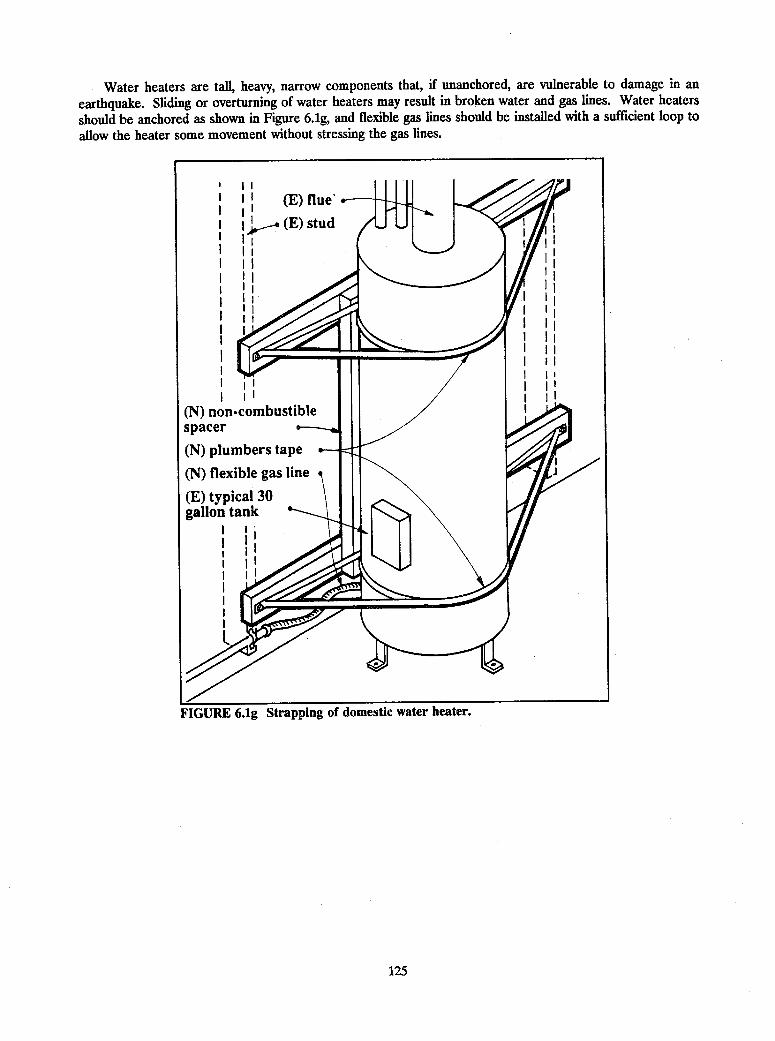
Water heaters are tall, heavy, narrow components that, if unanchored, are vulnerable to damage in an
earthquake. Sliding or overturning of water heaters may result in broken water and gas lines. Water heaters
should be anchored as shown in Figure 6.1g, and flexible gas lines should be installed with a sufficient loop to
allow the heater some movement without stressing the gas lines.
of domestic water heater.
125

6.2 DUC'IWORK AND PIPING
Seismic retrofit of ductwork and piping primarily consists of providing lateral sway braces. The Sheet Metal andAir-Conditioning Contractors National Association (SMACNA) has published guidelines for the design of seismicrestraints of new mechanical systems and plumbing piping systems (September 1982) that can also be used forrehabilitation of existing systems. These guidelines were developed for use in areas of relatively high seismicityand engineering judgment should be utilized in their application elsewhere. The SMACNA guidelines for seismicbracing of ductwork recommend that:
1. All rectangular ducts 6 square feet in area and greater and round ducts 28 inches in diameter and largershould be seismically braced.
2. Transverse braces should be installed at a maximum of 30 feet on center, at each duct turn, and at each endof a duct run.
3. Longitudinal braces should be installed at a maximum of 60 feet on center.
4. No bracing is required if the top of a duct is suspended 12 inches or less from the supporting structuralmember and the suspension straps are attached to the top of the duct.
The SMACNA guidelines for seismic bracing of piping recommend that:
1. Braces for all pipes 2-1/2 inches in diameter and larger (and also for smaller piping used for fuel gas, oil,medical gas, and compressed air and smaller piping located in boiler rooms, mechanical equipment rooms,and refrigeration machinery rooms).
2. Transverse braces should be installed at a maximum of 40 feet on center.
3. Longitudinal braces should be installed at a maximum of 80 feet on center.
4. Thermal expansion and contraction forces, where present, must be considered in the layout of transverseand longitudinal braces.
5. Flexibility should be provided where pipes pass through seismic or expansion joints.
Figures 6.2a through 6.2c show typical seismic brace details for ducting. Duct diffusers also should be positivelyattached with mechanical anchors to rigid ducts or secured with wires to the floor above when connected toflexible ducts. Figures 6.2d through 6.2g show typical details for installing seismic braces for piping.
126

I I
l~~~~~~~~~~~~~~~~~~~~~~~~~(N) angle brace
.0(N) straparound duct
FIGURE 6.2a Lateral and longitudinal braces for large-diameter ducting.
127

FIGURE 62b Lateral and longitudinal braces
128
-for small-diameter ducting.

FIGURE 6.2c Lateral and longitudinal braces for rectangular ducting.
129
(N) angle brace
(E) duct

(N) pipe clamp
FIGURE 6.2d Lateral braces for piping.
130
(N) channel
(N) straparound pipe

(N) angle brace
(E) pipe
(N) pipe clamp
(N) angle brace
(E) pipe
FIGURE 6.2e Longitudinal pipe brace.
131

FIGURE 6.2f Lateral brace for multiple pipes.
FIGURE 6.2g Longitadinal brace for multiple pipes.
1132
(N) angle brace
(E) pipe
(N) straparound pipe
(N) angle brace
(E) pipe
(N) straparound pipe

6.3 ELEVATORS
Elevator machinery and controller units should be anchored like other mechanical and electrical equipment toprevent the units from sliding or toppling. Rope retainer guards should be provided on sheaves to inhibitdisplacement of wire ropes. Snag points created by rail brackets should be provided with guards so thatcompensating ropes or chains, governor ropes, suspension ropes, and traveling cables will not snag. Retainerplates should be added to the top and bottom of the cars and counterweights to prevent them from becomingdislodged from the rails. Seismic switches should be installed to provide an electrical alert or command for thesafe automatic emergency operation of the elevator system and to detect lateral motion of the counterweight.For more information on the requirements for elevator seismic safety refer to ANSI 17.1, Safety Codes forElevators and Escalators.
6.4 EMERGENCY POWER SYSTEMS
Although emergency power systems typically containing batteries, motor generators, fuel tanks, transformers,switchgear, and control panels are designed to be activated in the event of an emergency, many are inadequatelyprotected from earthquake forces.
Batteries are frequently stored in racks as shown in Figure 6.4a, and structural members should be installedto restrain the batteries to theracks, the racks should be
(N) foam spacers A d G braced, and adequate anchorag-( foam spacers e es should be provided to carry
(N) restraining the lateral loads. Foam spacersmembers also should be fitted snugly
between the batteries to pre-vent them from impacting eachother.
Motor generators typicallyare mounted on vibration isola-tors, and these units shouldhave seismic stops installed asshown in Figures 6.1d or 6.1e.Fuel tanks frequently aremounted on legs to facilitategravity feed of the fuel, andthese tanks should be braced asshown in Figure 6.4b and pro-vided with adequate anchorage.Flexible fuel piping with ade-quate loops also should beinstalled both at the fuel tankand at the motor generator,
oo k v \ (/ [ ~transformers, switchgear, andcontrol panels should be an-chored as shown in Figure 6.1b.
FIGURE 6Aa Bracing of existing battery racks.
133

(N) brace
(E) leg
(N) anchor bolt
FIGURE 6Ab Bracing of horizontal tank.
134

6.5 HAZARDOUS MATERIAL STORAGE SYSTEMS
Seismic-activated shutoff valves should be installed on hazardous materials supply lines. These lines also shouldbe adequately braced as shown in Figures 6.2e and 6.2f and should be provided with flexible connections atstorage tanks. Bottles of laboratory chemicals should be prevented from falling by using elastic straps or shelflips as shown in Figure 6.5a. Liquid oxygen and similar pressurized tanks also should be restrained as indicatedin Figure 6.5b.
FIGURE 6.5a Protective measures for hazardous materials.
135

(E) gas cylinder
(N) chain restraint
FIGURE 6.5b Anchorage detail for pressurized tanks.
136

6.6 COMMUNICATIONS SYSTEMS
The operation of communication systems following an earthquake is of vital importance to individuals,communities, federal agencies, and private businesses that depend on them to aid in assessing damage andresponding to problems.
Telephone communications equipment consists of input and output data processing units, disk drives, centralcomputers, and remote regional and central switching units, much of which is located on raised access floors;this computer type equipment is discussed in Sec. 6.7. Remote switching units not located on raised floors shouldbe secured like other mechanical and electrical equipment as discussed in Sec. 6.1.
Essential facilities such as hospitals and fire and police stations that must have communication capabilitiesin the event of an earthquake should have backup external and internal communication systems. Radioequipment should be secured to prevent sliding or toppling. Desk top equipment also should be secured ortethered to prevent falling.
6.7 COMPUTER EQUIPMENT
Computer equipment vulnerable to seismic damage includes electronic data processing equipment such as main-frames, peripherals, telecommunications cabinets, and tape and disk storage units. Seismic rehabilitation toprotect computer equipment is different from that required for other mechanical and electrical equipment forseveral reasons: (1) computer equipment typically is located on raised access floors that complicate traditionalanchorage techniques and may amplify seismic loads, (2) computer equipment design is rapidly evolving andadvancing, units frequently are replaced or rearranged, and (3) some computer equipment may be sensitive tohigh-frequency vibrations such as those that may be caused by ground shaking.
The remainder of this section briefly identifies rehabilitation techniques for data processing equipment andtape and disk storage racks. For more information on the subject, refer to Data Processing Facilities: GuidelinesforEarthquake Hazard Mitigation (Olson, 1987), which provides detailed seismic design recommendations for newcomputer facilities and the rehabilitation of existing facilities.
Electronic data processing (EDP) equipment typically is located on raised access floors; hence, thetraditional techniques of anchoring electrical equipment to the floor are complicated by the fact that theanchorage needs to pass through the access floor to the subfloor. This reduces the access to the space beneaththe raised floor and greatly reduces the flexibility to rearrange and replace equipment. Some dynamic tests ofEDP equipment also have shown that certain vibration-sensitive equipment may be more prone to seismicdamage if it is rigidly anchored to the building and is subjected to high-frequency seismic ground motions thanif the equipment is free to slide on the access floor. However, if EDP units are unrestrained, they may slide intostructural walls or adjacent equipment or their support feet may slide into an access floor penetration, and theunit will topple.
Two general solutions may be used to reduce the potential for seismic damage of EDP equipment: rigidlyrestraining the equipment or allowing the equipment to slide. Rigid restraints (Figure 6.7a) may be appropriatefor equipment that is not vibration-sensitive, is not likely to be relocated, or is tall and narrow (and, hence,susceptible to toppling). Air-handling units, modem cabinets, and power distribution units fall into this category.Tall, flexible equipment such as modem cabinets may require stiffening or bracing near the top. If anchored onlyat the base, the seismic motions at the top of the units may be significantly amplified and may result inequipment damage. Figure 6.7b shows a detail that will prevent toppling but does not transmit high-frequencyground shaking to the unit.
Equipment that is vibration sensitive or is likely to require frequent relocation can be isolated to reduce thepotential for seismic damage. Some of the considerations necessary for isolating equipment include protectingthe equipment from sliding to prevent a supporting foot or caster from falling into an opening in the access floor(provided for cable penetrations). This can be prevented by tethering the equipment to the subfloor (Figure6.7c) so that the equipment cannot slide far enough to impact other equipment or walls or to fall into apenetration. Precautions should be considered for tall equipment restrained with a tether to prevent theequipment from reaching the end of the tether, which may cause the equipment to overturn. Floor penetrationsalso can be provided with guards (Figure 6.7c) that will prevent the equipment feet from entering. Adjacent
137

equipment either should be separated by about 1 foot to prevent potential pounding or should be strapped
together (Figure 6.7d) so that the separate pieces move as a unit.
FIGURE 6.7a Rigid anchorage of computer equipment.
138
(N) anchor11 -b
I ': aI . - _.
.
. 6

FIGURE 6.7b Flexible anchorage of computer equipment.
139
(E) computerequipment
(E) leveling pads
(N) tension rods
(N) turnbuckle
(N) expansionanchor

FIGURE 6.7c Tether andequipment.
140

FIGURE 6.7d Strapping of electronic data processing units.
141

BIBLIOGRAPHY
ABK. 1981. Methodology for Mitigation of Seismic Hazards in Existing Unreinforced Masonry Buildings:Categorization of Buildings. Washington, D.C.: National Science Foundation.
American National Standards Institute. 1987. Safety Code for Elevators, "Appendix F - Recommended ElevatorSafety Requirements for Seismic Risk Zone 3 or Greater," ANSI 17.1.
Applied Technology Council. 1986. Base Isolation and Passive Energy Dissipation: Proceedings of a Seminarand Workshop, ATC-17. Redwood City, California: Applied Technology Council.
Applied Technology Council. 1987. Evaluating the Seismic Resistance of Existing Buildings, ATC-14. RedwoodCity, California: ATC.
Applied Technology Council. 1988. Rapid Jsual Screening of Buildings for Potential Seismic Hazards, ATC-21.Redwood City, California: ATC.
Applied Technology Council. 1989. Seismic Evaluation of Existing Buildings: (Preliminary), ATC-22, FEMA 178.Washington, D.C.: FEMA.
Applied Technology Council. 1989. Seismic Evaluation of Existing Buildings: Supporting Documentation,ATC-22-1, FEMA 175. Washington, D.C.: FEMA.
Arioclu, Ersin, K. Anadol, E. Gunol, E. Akar, and A. Candogan. 1978. "Aseismic Design and Construction ofa Precast Concrete Industrial Center with Some Test Results." In the Proceedings of the Sixth EuropeanConference on Earthquake Engineering.
Arnold, Christopher, and Robert Reitherman. 1982. Building Configuration and Seismic Design. New York:John Wiley and Sons, 1982.
Ayres, J. Marx, and Tseng-Yao Sun. 1972. Earthquake Resistive Construction for Mechanical Systems, LightFixtures and Ceilings, Report of the Los Angeles Unified School District. Los Angeles, California, Los AngelesUnified School District.
Battey, Jr., George E. 1982. "Materials Evaluation," in FIX'EM: Identification and Correction of Deficienciesin Earthquake Resistance of Existing Buildings, Earthquake Engineering Research Institute Seminar. Oakland,California: Earthquake Engineering Research Institute.
Benedetti, D., and E. Vitiello. 1978. "Strengthening of Masonry Buildings." In Proceedings of the Seminar onConstructions in Seismic Zones, Bergamo-Udine, Italy, International Association for Bridge and StructuralEngineering.
Boardman, P., B. Wood, and A. Carr. 1986. "Union House--A Cross Braced Structure with Energy Dissipators."In Proceedings of a Seminar and Workshop on Base Isolation and Passive Energy Dissipation, ATC-17. RedwoodCity, California: Applied Technology Council.
Bolong, Zhu, Jiang Zhixian, and Wu Mingshun. 1982. "A Study on Aseismic Capacity of Brick MasonryBuildings Strengthened with Reinforced Concrete Columns and Tie Bars." In Proceedings of U.S. -- People'sRepublic of China Bilateral Workshop on Earthquake Engineering, Vol. 1.
143

Breiholz, David C. 1987. "Centercore Strengthening System for Seismic Hazard Reduction of UnreinforcedMasonry Bearing Wall Buildings." Paper prepared for the Structural Engineering Association of California 56thAnnual Convention.
Building Seismic Safety Council. 1988 and 1991. NEHRP Recommended Provisions for the Development ofSeismic Regulations for New Buildings, 2 vols. and maps. Washington, D.C.: Federal Emergency ManagementAgency.
Building Seismic Safety Council. 1992. NEHRP Handbook for the Seismic Evaluation of Existing Buildings.Washington, D.C.: Federal Emergency Management Agency.
Cagley, James R. 1978. Seismic Hardening of Unreinforced Masonry Walls through a Surface Treatment.Washington, D.C.: National Science Foundation.
Clark, W. D., and 0. A. Glogau. 1979. "Suspended Ceilings: The Seismic Hazard and Damage Problem andSome Practical Solutions." In Proceedings of the South Pacific Regional Conference on Earthquake Engineering,Vol. 3.
Clough, R., and J. Penzien. 1975. Dynamics of Structures. New York: McGraw-Hill.
Davis, Harold A. 1978. "The Center for Educational Development, a Medium Scale Seismic Upgrading." InProceedings of the North American Masonry Conference.
Departments of the Army, the Navy and the Air Force. 1982. Seismic Design for Buildings, Army TM 5-809-10,Navy NAVFAC P-355, AFM 88-3, Chap. 13. Washington, D.C.: U.S. Government Printing Office.
Departments of the Army, the Navy, and the Air Force. 1988. Seismic Design Guidelines for Upgrading ExistingBuildings," Army TM 5-809-10-2, Navy NAVFAC P-355.2, AFM 88-3, Chap. 13, Sec. B. Washington, D.C.: U.S.Government Printing Office.
Departments of the Army, the Air Force, and the Navy. 1986. Seismic Design Guidelines for Essential Buildings,Army TM 5-809-10.1, Navy NAVFAC P355.1, AFM 88-3, Chap. 13.1. Washington, D.C.: U.S. GovernmentPrinting Office.
Dynamic Isolation Systems. 1988. Seismic Isolation of Buildings, Workshop Proceedings. Berkeley, California:Dynamic Isolation Systems, Inc.
Earthquake Engineering Research Institute. 1984. Nonstructural Issues of Seismic Design and Construction,"Technical Evaluation Based on a Workshop of the National Science Foundation. Oakland, California:Earthquake Engineering Research Institute.
ED2 International. 1985. Suspended Ceiling System Survey and Seismic Bracing Recommendations. Survey ofthe Lawrence Livermore National Laboratory.
Endo, T., A. Okifuji, S. Sugano, T. Hayashi, T. Shimizu, K. Takahara, H. Saito, and Y. Yoneyama. 1984."Practices of Seismic Retrofit of Existing Concrete Structures in Japan." In Proceedings of the Eighth WorldConference on Earthquake Engineering.
Forell, Nicholas F. 1983. "Structural Engineering Considerations." In Workshop Proceedings of the EarthquakeDamage Mitigation for Computer Systems for the Finance, Insurance and Monetary Services Committee, Califomia.
Gates, William E., and Charles Scawthorn. 1983. 'Mitigation of Earthquake Effects on Data Processing andTelecommunications Equipment." In Workshop Proceedings of the Earthquake Damage Mitigation for ComputerSystems for the Finance, Insurance and Monetary Services Committee, Califomia.
144

Georgescu, Emil Saver. 1982. "Seismic Risk Mitigation of Rural Houses Using Performance CoefficientsSelections." In Proceedings of the Seventh European Conference on Earthquake Engineering Athens, Greece.
Giuliani, Hugo. 1980. "Supporting, Recovery, and Strengthening of Southeastern Block of School, "ENET No.2" Affected by Caucete Earthquake of November 1977." Bulletin of the Intemational Institute of Seismology andEarthquake Engineering 18.
Goodno, B. J., J. I. Craig, M. Mayyappa, and H. Palsson. 1983. Cladding-Structure Interaction in HighriseBuildings, Report of the National Science Foundation Civil and Environmental Engineering Earthquake HazardsMitigation. Washington, D.C.: National Science Foundation.
Graff, Edward D., and Edwin G. Zacher. 1979. "Sand to Sandstone: Foundation Strengthening with ChemicalGrout." Civil Engineering (January).
Hanson, R. 1988. "Energy Dissipation Systems." In Proceedings of the 1988 Structural Engineers Associationof California Convention, Kona, Hawaii.
Hanson, Robert D. 1977. "Repair, Strengthening, and Rehabilitation of Buildings." In Workshop Proceedings,National Science Foundation Report. Washington, D.C.: National Science Foundation.
Hawkins, Neil M., and J. F. Stanton. 1982. "Building Rehabilitation Strategies in Seattle, Washington." InProceedings of U.S.-People's Republic of China Bilateral Workshop on Earthquake Engineering, Vol. 1.
Higashi, Yoichi, and Seiji Kokusho. 1975. "The Strengthening Methods of Existing Reinforced ConcreteBuildings." In Proceedings of the U.S.-Japan Cooperative Research Program.
Holmes, William T. 1979. "The Rehabilitation of History Corner of the Stanford University Main Quad." InProceedings of the 2nd U.S. National Conference on Earthquake Engineering.
Holmes, William T. 1982. "Nonstructural Components." In FLX'EM: Identification and Correction of Deftcienciesin Earthquake Resistance of Existing Buildings, Earthquake Engineering Research Institute Seminar. Oakland,California: Earthquake Engineering Research Institute.
Hom, Stephen, Raymond Kincaid, and Peter I. Yanev. 1986. Practical Equipment Seismic Upgrade andStrengthening Guidelines, Report of Lawrence Livermore National Laboratory.
Hopkins, David C. 1987. "Recommendations for Strengthening Earthquake Risk Buildings in New Zealand."In Proceedings of the Pacific Conference on Earthquake Engineering, New Zealand.
Iwan, Wilfred D. 1983. "Mitigating Seismic Losses to Computer Facilities." In Workshop Proceedings of theEarthquake Damage Mitigation for Computer Systems for the Finance, Insurance and Monetary Services Committee,California.
Jacobsen, L. 1930. "Steady State Forced Vibration as Influenced by Damping." Transactions, ASME, Vol. 52,Part 1, pp. APM 169-181.
Jordan, Carl H. 1977. "Seismic Restraint of Mechanical and Electrical Equipment in Buildings." In Report fromthe American Society of Civil Engineers Meeting in San Francisco.
Kariotis, Kesler, and Allys. 1978. "Mitigation of Seismic Hazards in Existing Unreinforced Masonry WallBuildings: Performance of Undesigned and Modified Elements. Evaluation of Modification Method." Bulletinof The New Zealand National Society for Earthquake Engineering 11(4).
145

Kawamata, Shigeya, Mamoru Yoneda, and Yasuhiko Hangai. 1973. Development of a Vibration Control System
for Structures by Means of "Mass Pumps, " Bulletin No. 7 of the Earthquake Resistance Structure Research Center.
Kay, Donald R. 1982. "Correction of Deficiencies in Reinforced Concrete Buildings." In FIX'EM:
Identification and Correction of Deficiencies in EarthquakeResistance of EtistingBuildings, EarthquakeEngineeringResearch Institute Seminar. Oakland, California: Earthquake Engineering Research Institute.
Kelly, James M. and Douglas Way. 1982. "The Seismic Rehabilitation of Existing Buildings Using Natural
Rubber Bearings." In Proceedi -k of the 51st Annual Convention of the Structural Engineers Association of
California.
Kelly, James M. 1979. "Aseismic Base Isolation: A Review." In Proceedings of the 2nd U.S. National
Conference on Earthquake Engineering.
Knoll, Franz. 1983. "Upgrading Seismic Resistance of Buildings for Moderate Earthquake Risk." The Journal
of Earthquake Wind and Ocean Engineering, Eng. Struc. 5(2).
Korenev, B. G., and V. S. Poliakov. 1978. "Reduction of Seismic Structural Response Using the Vibration
Absorber." In Proceedings of the Sixth European Conference on Earthquake Engineering.
Lagorio, Henry J., Howard Friedman, and Kit M. Wong. 1986. Issues for Seismic Strengthening of Existing
Buildings: A Practical Guide forArchitects. Berkeley: University of California Center for Environmental Design
Research.
Lybas, J. M. 1978. Methods for Seismic Strengthening of Buildings," Report M249 of the Construction
Engineering Research Laboratory.
Marinakis, Kleon. 1978. "A Way to Increase the Resistance of Supporting Structures that are Already Built
Against Seismic Forces." Paper for the Hellenic Institute for the Application of Science, Athens, Greece,
Seminar on Constructions in Seismic Zones, Bergamo-Udine, Italy, International Association for Bridge and
Structural Engineering, May.
Martin, Ignacio. 1987. "Seismic Rehabilitation: Why, When, and How." In Mexico Earthquakes-1985,
Proceedings of the International Conference. New York: American Society of Civil Engineers.
McGavin, Gary L. 1981. Earthquake Protection of Essential BuildingEquipment: Design Engineering Installation.
New York: John Wiley & Sons.
Mihlailescu, M, I. Olariu, and N. Poienar. 1990. "Strengthen By Porestressing of a Multistory Frame Building."
In Proceedings of the Symposia on Partial Prestressing and Practical Construction in Prestressed and Reinforced
Concrete.
Mullins, Peter J., and Colin O'Connor. 1987. "Reinforcement of Brick Walls Spanning Vertically." Journal of
Structural Engineering 113(2).
New Zealand National Society for Earthquake Engineering. 1985. Recommendations and Guidelines for
Classifying, Interim Securing and Strengthening Earthquake Risk Buildings.
Newmark, N., and W. Hall. 1982. Earthquake Spectra and Design. Oakland, California: Earthquake
Engineering Research Institute.
Niu, Zezhen. 1982. "Calculating Methods of Strengthened and Repaired Brick Masonry Structures for
Earthquake Resistance." In Proceedings of U.S.-People's Republic of China Bilateral Workshop on Earthquake
Engineering, Vol. 1.
146

Okada, T., M. Murakami, M. Seki, and A. Ando. 1983. "Repair and Strengthening of Reinforced ConcreteBuildings." In Proceedings of the Intemational Association for Bridge and Structural Engineering Symposium,Vienna, Vol. 46.
Oliveira, Carlos S., and Artur Ravara. 1978. "Methodology for Strengthened Existing Structures Built withoutthe Required Earthquake Resistance." In Proceedings of the Sixth European Conference on EarthquakeEngineering.
Olson, RA. 1987. Data Processing Facilities: Guidelines for Earthquake Hazard Mitigation. California:Financial Insurance and Monetary Services Committee.
Ozmen, Gunay. 1982. "Redesign Considerations." In Proceedings of the Ninth Regional Seminar on EarthquakeEngineering, Vol. 1, Turkish National Committee for Earthquake Engineering Publication 2.
Plecnik, Joseph, Thomas Cousins, and Edward O'Conner. 1986. "Strengthening of Unreinforced MasonryBuildings." Journal of Structural Engineering 112 (5).
Popov, E., and M. Engelhardt. 1987. "Seismic Eccentrically Braced Frames." Journal of Constructional SteelResearch (United Kingdom).
Prawal, S. P., and A. M. Reinhorn. 1985. "Seismic Retrofit of Structural Masonry Using a FerrocementOverlay." In Proceedings of the Third North American Masonry Conference.
Rea, D. 1968. Discussion on "Equivalent Viscous Damping for Yielding Structures." Journal of the StructuralDivision 94(EM6).
Reitherman, R. 1985. Reducing the Risks of Nonstructural Earthquake Damage: A Practical Guide. Oakland,California: Bay Area Regional Earthquake Preparedness Project.
San Bernadino County Department of Economic and Community Development. 1987. Seismic Strengthening,Final Report and Handbooks. San Bernadino, California: County Department of Economic and CommunityDevelopment.
Scalzi, John B. 1983 "Strengthening of Masonry Buildings in the United States." In Proceedings of the ABSESymposium, Vienna, Vol. 46.
Schmid, Ben L. 1982. "Special Problems Related to Masonry Structures." In FIX'EM: Identification andCorrection of Deficiencies in EarthquakeResistance of ExistingBuildings, Earthquake EngineeringResearch InstituteSeminar. Oakland, California: Earthquake Engineering Research Institute.
Scholl, R. E. In press. Earthquake Resistant Design Using Added Damping and Stiffness Elements.
Shapiro, Okino, Hom and Associates for the Applied Technology Council. 1980. The Home Builder's Guide forEarthquake Design. Prepared for the Department of Housing and Urban Development, Office of PolicyDevelopment and Research. Washington, D.C.: U.S. Government Printing Office.
Sheet Metal and Air Conditioning Contractors National Association. 1982. Guidelines for Seismic Restraints ofMechanical Systems and Plumbing Piping Systems. Place: Sheet Metal and Air Conditioning ContractorsNational Association.
Stone, Marraccini and Patterson. 1976. Study to Establish Seismic Protection Provisions for Fumiture, Equipmentand Supplies for VA Hospitals. Washington, D.C.: Veterans Administration.
147

Structural Engineers Association of California. 1986. "Earthquake Hazard Mitigation of Unreinforced Pre-1933Masonry Buildings." In Technical Manual Containing Papers on the Use of the Proposed Rule of GeneralApplication and Alternate Design Approach to the Reduction of Earthquake Hazards Seminar, Structural EngineersAssociation of Southern California.
Sugano, Shunsuke. 1982. "An Overview of the State-of-the-Art In Seismic Strengthening of Existing ReinforcedConcrete Buildings in Japan." In Proceedings of the Third Seminar of Repair and Retrofit of Structures.
Sugano, S. 1981. "Guideline for Seismic Retrofitting (Strengthening, Toughening and/or Stiffening) Design ofExisting Reinforced Concrete Building." In Proceedings of the Second Seminar of Repair and Retrofit ofStructures.
Thomson, W. 1972. Theory of Vibration. Englewood Cliffs, New Jersey: Prentice-Hall.
United Nations Industrial Development Organization. 1983. Building Construction Under Seismic Conditionsin the Balkan Region, Vol. 5.
URS/John A. Blume and Associates. 1989. Techniques for Seismically Rehabilitating Existing Buildings(Preliminary). Washington, D.C.: FEMA.
Warner, James. 1980. "Repair and Retrofit of Buildings Overview of U.S. Experiences -- Current Practice andWeaknesses." In Proceedings of the First Seminar of Repair and Retrofit of Structures.
Warner, James. 1976. "Ventura City Hall Restoration." Joumal of the Construction Division 102(March).
Wong, Kit M. 1987. Seismic Strengthening of Unreinforced Masonry Buildings. Berkeley, California: Center forEnvironmental Design Research.
Woodhead, Roger, and D. R. Morgan. 1983. "Block 15 Heritage Redevelopment Seismic Upgrading." InProceedings Fourth Canadian Conference on Earthquake Engineering, Vancouver.
Wyllie, Jr., Loring A. 1983. "Seismic Strengthening Procedures for Existing Structures." In Proceedings of theInternational Association of Bridge and Structural Engineering Symposium, ienna, Vol. 46.
Wyllie, Jr., Loring A. 1981. "Strengthening Existing Concrete and Masonry Buildings for Seismic Resistance."In Proceedings of- the Second Seminar of Repair and Retrofit of Structures, Structural Engineers Association ofNorthern California.
Yanev, Peter I. 1983. "Earthquake Risk-Reduction and Control for Computer Systems." In Proceedings of theWorkshop on Earthquake Damage Mitigation for Computer Systems for the Finance, Insurance and MonetaryServices Committee.
Yongsong, Gong. 1982. "Aseismic Evaluation of Brick Structures." In Proceedings of U.S. - People's Republicof China Bilateral Workshop on Earthquake Engineering, Vol. 1.
Zarnic, Roko, Miha Tomazevic, and Tomaz Velechovsky. 1986. "Experimental Study of Methods for Repairand Strengthening of Masonry Infilled Reinforced Concrete Frames." In Proceedings of the 8th EuropeanConference on Earthquake Engineering.
Zarnic, Roko, and Miha Tomazevic. 1986. "Aseismic Strengthening of an Historical XVII-Century UrbanBuilding--A Case Study." In Proceedings of the 8th European Conference on Earthquake Engineering.
148

APPENDIX A
SEISMIC-FORCE-RESISTING ELEMENTSIN BUILDINGS
This handbook discusses techniques for rehabilitating the seismic resistance of the following 15 common buildingtypes:
1. Wood Light Frame2. Wood, Commercial and Industrial3. Steel Moment Frame4. Steel Braced Frame5. Steel Light Frame6. Steel Frame with Concrete Shear Walls7. Steel with Infill Masonry Shear Walls8. Concrete Moment Frame9. Concrete Shear Walls10. Concrete Frame with Infill Walls11. Precast/Tilt-Up Concrete Walls with Lightweight Flexible Diaphragm12. Precast Concrete Frames with Concrete Shear Walls13. Reinforced Masonry Bearing Walls with Wood/Metal Deck Diaphragms14. Reinforced Masonry Bearing Walls with Precast Concrete Diaphragms15. Unreinforced Masonry Bearing Wall Buildings
The lateral-force-resisting elements of buildings can be categorized into the following subsystems: verticalelements resisting lateral forces, diaphragms, foundations, and the connections between the subsystems. The 15common building types considered in this report can be composed of various subsystem types. The constructionof each subsystem can vary. For example, diaphragms can be constructed of timber, steel or concrete. Thetechnique to rehabilitate a deficient subsystem and hence a deficient building depends upon the type ofconstruction of that subsystem. The following tables present common construction of the lateral-force-resistingsubsystems for the 15 common building types. These tables are provided to aid the reader in determining thetypes of subsystems likely to be present in a building of a given type. With an understanding of the subsystemconstruction and the subsystem deficiencies, the techniques presented in Chapter 3 can be investigated todetermine effective ways to rehabilitate the seismic resistance of a given existing building.
149

TABLE AlSTRUCTURAL ELEMENTS OF COMMON BUILDING TYPE 1--WOOD, LIGHT FRAME
150
Floor or Roof Vertical-ResistingDiaphragm Elements Foundations Connections
Timber framing with Wood stud walls with Spread footings, piles, Diagonal wire or strutplywood, straight-laid, let-in or cut-in timber or drilled piers. bracing of ceilings fromor diagonal sheathing. bracing or plywood, floor or roof diaphragms.
straight-laid, or diago-nal sheathing. Bracing or lateral support
of walls and partitions fromceilings or diaphragms.
Nailing and blocking for di-rect shear transfer fromhorizontal diaphragms toshear walls or vertical brac-ing.
Drag struts to collect shearfrom horizontal diaphragmsfor transfer to shear wallsor vertical bracing.
Bolting of shear walls andvertical bracing to concreteslabs or foundation walls.
Tension ties or hold-downsfor shear walls and verticalbracing.
Nailing or bolting of verti-cal bracing.

TABLE A2STRUCTURAL ELEMENTS OF COMMON BUILDING TYPE 2--WOOD, COMMERCIAL AND
INDUSTRIAL
151
Floor or Roof Vertical-ResistingDiaphragm Elements Foundations Connections
Timber framing with Wood stud walls with Spread footings, piles, Diagonal wire or strut brac-plywood, straight-laid, let-in or cut-in timber or drilled piers. ing of ceilings from floor oror diagonal sheathing. bracing or plywood, roof diaphragms.(Floor or roof deck- straight-laid, or diag-ing may be 2-inch onal sheathing. Bracing or lateral support ofmaterial). walls and partitions from
Knee bracing or diag- ceilings or diaphragms.onal bracing of timbercolumns. Nailing and blocking for di-
rect shear transfer fromhorizontal diaphragms toshear walls or vertical brac-ing.
Drag struts to collect shearfrom horizontal diaphragmsfor transfer to shear walls orvertical bracing.
Bolting of shear walls andvertical bracing to concreteslabs or foundation walls.
Tension ties or hold-downsfor shear walls and verticalbracing.
Nailing or'bolting of verticalbracing.

TABLE A3
STRUCTURAL ELEMENTS OF COMMON BUILDING TYPE 3--STEEL MOMENT FRAME
Floor or Roof Vertical-ResistingDiaphragm Elements Foundations Connections
Timber framing withplywood, straight-laid,or diagonal sheathing.
Reinforced concreteslab supported onstructural steel floorframing members.
Steel decking with orwithout concrete fill.
_____________ J.
Moment resisting*structural steel frames.
Spread footings, piles,or drilled piers.
Diagonal wire or strut brac-ing of ceilings from floor orroof diaphragms.
Bracing or lateral supportwalls and partitions fromceilings or diaphragms.
of I
Nailing and blocking for di-rect shear transfer fromhorizontal diaphragms toshear walls or vertical brac-ing.
Drag struts to collect shearfrom horizontal diaphragmsfor transfer to shear walls orvertical bracing.
Shear studs or other connec-tions of concrete diaphragmto steel chord members.
Welding, shear studs, orother connections of steeldeck diaphragms to struc-tural steel framing.
Splice detail of steel chordmembers.
Beam/column connections.
Beam/column panel jointdetails.
Column splice details.
Column base details.
152
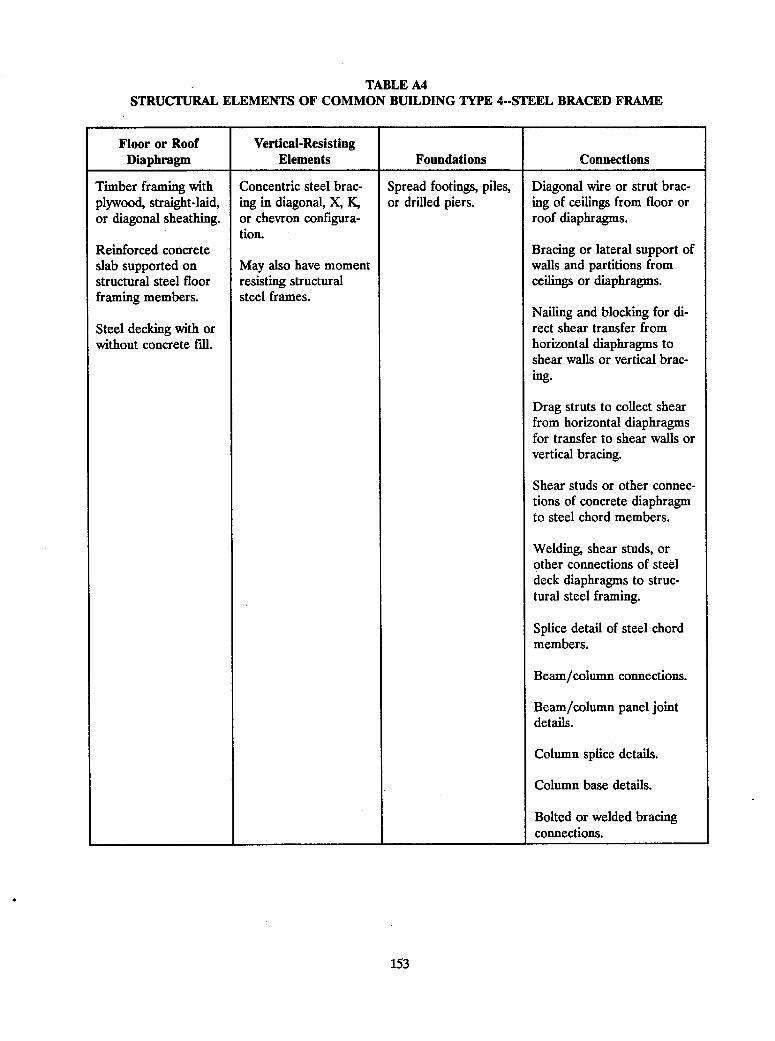
TABLE A4STRUCTURAL ELEMENTS OF COMMON BUILDING TYPE 4--STEEL BRACED FRAME
Floor or Roof Vertical-ResistingDiaphragm Elements Foundations Connections
Timber framing withplywood, straight-laid,or diagonal sheathing.
Reinforced concreteslab supported onstructural steel floorframing members.
Steel decking with orwithout concrete fill.
Concentric steel brac-ing in diagonal, X, K,or chevron configura-tion.
May also have momentresisting structuralsteel frames.
Spread footings, piles,or drilled piers.
Diagonal wire or strut brac-ing of ceilings from floor orroof diaphragms.
Bracing or lateral support ofwalls and partitions fromceilings or diaphragms.
Nailing and blocking for di-rect shear transfer fromhorizontal diaphragms toshear walls or vertical brac-ing.
Drag struts to collect shearfrom horizontal diaphragmsfor transfer to shear walls orvertical bracing.
Shear studs or other connec-tions of concrete diaphragmto steel chord members.
Welding, shear studs, orother connections of steeldeck diaphragms to struc-tural steel framing.
Splice detail of steel chordmembers.
Beam/column connections.
Beam/column panel jointdetails.
Column splice details.
Column base details.
Bolted or welded bracingconnections.
153

TABLE ASSTRUCTURAL ELEMENTS OF COMMON BUILDING TYPE 5--STEEL, LIGHT FRAME
Floor or Roof Vertical-ResistingDiaphragm Elements Foundations Connections
Timber framing withplywood, straight-laid,or diagonal sheathing.
Reinforced concreteslab supported onstructural steel floorframing members.
Steel decking with orwithout concrete fill.
Moment resistingstructural steel frames.
Concentric light steelbracing in diagonal orX configuration.
Spread footings, piles,or drilled piers.
Diagonal wire or strut brac-ing of ceilings from floor orroof diaphragms.
Bracing or lateral support ofwalls and partitions fromceilings or diaphragms.
Nailing and blocking for di-rect shear transfer fromhorizontal diaphragms toshear walls or vertical brac-ing.
Drag struts to collect shearfrom horizontal diaphragmsfor transfer to shear walls orvertical bracing.
Shear studs or other connec-tions of concrete diaphragmto steel chord members.
Welding, shear studs, orother connections of steeldeck diaphragms to struc-tural steel framing.
Splice detail of steel chordmembers.
Beam/column connections.
Beam/column panel jointdetails.
Column splice details.
Column base details.
Bolted or welded bracingconnections.
154
.1I
L I

TABLE A6STRUCTURAL ELEMENTS OF COMMON BUILDING TYPE 6--STEEL FRAME WITH CONCRETE
SHEAR WALLS
Floor or Roof Vertical-ResistingDiaphragm Elements Foundations Connections
Reinforced concreteslab supported onstructural steel floorframing members.
Steel decking with orwithout concrete fill.
Nomnoment-resistingsteel frames.
Reinforced concreteshear walls.
May also have momentresisting structuralsteel frames.
Spread footings, piles,or drilled piers.
Diagonal wire or strut brac-ing of ceilings from floor orroof diaphragms.
Bracing or lateral support ofwalls and partitions fromceilings or diaphragms.
Shear studs or other connec-tions of concrete diaphragmto steel chord members.
Welding, shear studs, orother connections of steeldeck diaphragms to struc-tural steel framing.
Splice detail of steel chordmembers.
Beam/column connections.
Beam/column panel jointdetails.
Column splice details.
Column base details.
Connection of concreteshear walls to floor or roofdiaphragms.
Development of boundarymembers for concrete shearwalls.
155

TABLE A7
STRUCTURAL ELEMENTS OF COMMON BUILDING TYPE 7--STEEL WITH INFILL MASONRYSHEAR WALLS
Floor or Roof Vertical-Resisting 1Diaphragm Elements Foundations Connections
Timber framing withplywood, straight-laid,or diagonal sheathing.
Reinforced concreteslab supported onstructural steel floorframing members.
Steel decking with orwithout concrete fill.
Nonmoment-resistingsteel frames.
Unreinforced masonrywalls.
May also have momentresisting structuralsteel frames.
Spread footings, piles,or drilled piers.
_______________ A _______________ A. -
Diagonal wire or strut brac-ing of ceilings from floor orroof diaphragms.
Bracing or lateral support ofwalls and partitions fromceilings or diaphragms.
Nailing and blocking for di-rect shear transfer fromhorizontal diaphragms toshear walls or vertical brac-ing.
Drag struts to collect shearfrom horizontal diaphragmsfor transfer to shear walls orvertical bracing.
Shear studs or other connec-tions of concrete diaphragmto steel chord members.
Welding, shear studs, orother connections of steeldeck diaphragms to struc-tural steel framing.
Splice detail of steel chordmembers.
Beam/column connections.
Beam/column panel jointdetails.
Column splice details.
Column base details.
Connection of masonry wallsto steel framing.
156

TABLE A&
STRUCTURAL ELEMENTS OF COMMON BUILDING TYPE 8--CONCRETE MOMENT FRAME
157
Floor or Roof Vertical-ResistingDiaphragm Elements Foundations Connections
Reinforced concrete Reinforced concrete Spread footings, piles, Diagonal wire or strut brac-
slab monolithic with frames. or drilled piers. ing of ceilings from floor or
reinforced concrete roof diaphragms.beams and girders.
Bracing or lateral support ofwalls and partitions fromceilings or diaphragms.
Beam/column panel jointdetails.
Column shear reinforcementand confinement.

TABLE A9STRUCTURAL ELEMENTS OF COMMON BUILDING TYPE 9--CONCRETE SHEAR WALLS
158
Floor or Roof Vertical-ResistingDiaphragm Elements Foundations Connections
Reinforced concrete Reinforced concrete Spread footings, piles, Diagonal wire or strut brac-slab monolithic with shear walls. or drilled piers. ing of ceilings from floor orreinforced concrete roof diaphragms.beams and girders.
Bracing or lateral support ofwalls and partitions fromceilings or diaphragms.
Connection of concreteshear walls to floor or roofdiaphragms.
Development of boundarymembers for concrete shearwalls.
Concrete diaphragm chorddetails.
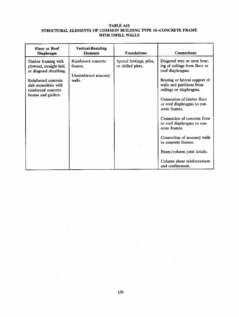
TABLE A10
STRUCTURAL ELEMENTS OF COMMON BUILDING TYPE 10--CONCRETE FRAMEWITH INFILL WALLS
159
Floor or Roof Vertical-ResistingDiaphragm Elements Foundations Connections
Timber framing with Reinforced concrete Spread footings, piles, Diagonal wire or strut brac-plywood, straight-laid, frames. or drilled piers. ing of ceilings from floor oror diagonal sheathing. roof diaphragms.
Unreinforced masonryReinforced concrete walls. Bracing or lateral support ofslab monolithic with walls and partitions fromreinforced concrete ceilings or diaphragms.beams and girders.
Connection of timber flooror roof diaphragms to con-crete frames.
Connection of concrete flooror roof diaphragms to con-crete frames.
Connection of masonry wallsto concrete frames.
Beam/column joint details.
Column shear reinforcementand confinement.

TABLE AllSTRUCTURAL ELEMENTS OF COMMON BUILDING TYPE 11--PRECAST/TILT-UP CONCRETE
WALLS WITH LIGHTWEIGHT FLEXIBLE DIAPHRAGM
Floor or Roof Vertical-ResistingDiaphragm Elements Foundations Connections
Timber framing withplywood, straight-laid,or diagonal sheathing.
Reinforced concreteslab monolithic withreinforced concretebeams and girders.
Steel decking with orwithout concrete fill.
Precast concrete walls. Spread footings, piles,or drilled piers.
Diagonal wire or strut brac-ing of ceilings from floor orroof diaphragms.
Bracing or lateral. support ofwalls and partitions fromceilings or diaphragms.
Welding, shear studs, orother connections of steeldeck diaphragms to struc-tural steel framing.
Connection of timber flooror roof diaphragms andprecast walls.
Connection of concrete flooror roof diaphragms to pre-cast walls.
Connection of steel deckfloor or roof diaphragms toprecast walls.
Vertical precast panel con-nections.
Tension ties or hold-downconnections for precast pan-els.
Diaphragm chord details fortimber, steel decking, andconcrete diaphragm.
Base detail for precast pan-els.
]
160

TABLE A12
STRUCTURAL ELEMENTS OF COMMON BUILDING TYPE 12--PRECAST CONCRETE FRAMESWITH CONCRETE SHEAR WALLS
161
Floor or Roof Vertical-ResistingDiaphragm Elements Foundations Connections
Reinforced concrete Precast concrete Spread footings, piles, Diagonal wire or strut brac-slab monolithic with frames. or drilled piers. ing of ceilings from floor orreinforced concrete roof diaphragms.beams and girders. Reinforced concrete
shear walls. Bracing or lateral support ofwalls and partitions fromceilings or diaphragms.
Connection of concrete flooror roof diaphragms to pre-cast frames or shear walls.
Development of boundarymembers for concrete shearwalls.
Beam/column joint details.
Column shear reinforcementand confinement.
Concrete frame splice de-tails.

TABLE A13STRUCTURAL ELEMENTS OF COMMON BUILDING TYPE 13--REINFORCED MASONRY WALLS
WITH WOOD/METAL DECK
162
Floor or Roof Vertical-ResistingDiaphragm Elements Foundations Connections
Timber framing with Unreinforced masonry Spread footings, piles, Diagonal wire or strut brac-plywood, straight-laid, bearing walls. or drilled piers. ing of ceilings from floor oror diagonal sheathing. roof diaphragms.
Steel decking with or Bracing or lateral support ofwithout concrete fill. walls and partitions from
ceilings or diaphragms.
Welding, shear studs, orother connections of steeldeck diaphragms to struc-tural steel framing.
Connection of timber orsteel decking floor or roofdiaphragms to masonrywalls.
Tension ties or hold-downsfor masonry walls.

TABLE A14
STRUCTURAL ELEMENTS OF COMMON BUILDING TYPE 14--REINFORCED MASONRY WALLSWITH PRECAST CONCRETE DECK
163
Floor or Roof Vertical-ResistingDiaphragm Elements Foundations Connections
Precast concrete units Reinforced masonry Spread footings, piles, Diagonal wire or strut brac-(planks, cored slabs, walls. or drilled piers. ing of ceilings from floor ortees, etc.) roof diaphragms.
Bracing or lateral support ofwalls and partitions fromceilings or diaphragms.
Connection of precast flooror roof units to shear walls.
Connections between adja-cent precast floor or roofunits.
Tension ties or hold-downsfor masonry walls.

TABLE A15STRUCTURAL ELEMENTS OF COMMON BUILDING TYPE 15-UNREINFORCED
MASONRY BEARING WALLS
164
Floor or Roof Vertical-ResistingDiaphragm Elements Foundations Connections
Timber framing with Unreinforced masonry Spread footings, piles, Diagonal wire or strut brac-plywood, straight-laid, walls. or drilled piers. ing of ceilings from floor oror diagonal sheathing. roof diaphragms.
Reinforced concrete Bracing or lateral support ofslab supported on walls and partitions fromstructural steel floor ceilings or diaphragms.framing members.
Connection of timber orReinforced concrete concrete floor or roof dia-slab monolithic with phragms to masonry walls.reinforced concretebeams and girders. Development of diaphragm
chords in timber or concretefloor or roof diaphragms.
Tension ties or hold-downsfor masonry walls.

APPENDIX B
SUMMARY OF STRENGTHENING TECHNIQUES
The deficiencies and alternative strengthening techniques discussed in Chapter 3 are summarized here as follows:
Table Bi Moment Resisting SystemsSteel Moment FramesConcrete Moment FramesMoment Frames with Infill WallsPrecast Concrete Moment Frames
Table B2 Shear WallsReinforced Concrete or Reinforced MasonryPrecast ConcreteUnreinforced MasonryShear Walls in Wood Frame Buildings
Table B3 Braced Frames
Table B4 Diaphragms
Table B5 Foundations
Table B6 Diaphragm to Vertical Element Connections
Table B7 Vertical Element to Foundation Connections
165

TABLE BiMOMENT RESISTING SYSTEMS
STEEL MOMENT FRAMES
DeficiencyI-
Inadequate moment/shear capacityof beams, columns, or their connec-tions
Strengthening Techniques
1. Increasing the moment capacity of the members and con-nections by adding cover plates or other steel sections to theflanges Or by boxing members.
2. Increasing the moment and shear capacity of the membersand connections by providing steel gusset plates or kneebraces.
3. Reducing the stresses in the existing frames by providingsupplemental vertical-resisting elements (i.e., additional mo-ment frames, braces, or shear walls) as discussed in Sec. 3.4.
4. Providing lateral bracing of unsupported flanges to increasecapacity limited by tendency for lateral/torsional buckling.
5. Encasing the columns in concrete.
Inadequate beam/column panel zone 1. Providing welded continuity plates between the column flang-
capacity es.2. Providing stiffener plates welded to the column flanges and
web.3. Providing web doubler plates at the column web.4. Reducing the stresses in the panel zone by providing sup-
plemental vertical-resisting elements (i.e., additional momentframes, braces, or shear walls) as discussed in Sec. 3.4.
Excessive drift 1. Increasing the capacity and, hence, the stiffness of the exist-ing moment frame by cover plates or boxing.
2. Increasing the stiffness of the beams and columns at theirconnections by providing steel gusset plates to form haunch-es.
3. Reducing the drift by providing supplemental vertical-resist-ing elements (i.e., additional moment frames, braces, orshear walls) as discussed in Sec. 3.4.
4. Increasing the stiffness by encasing columns in reinforcedconcrete.
5. Reducing the drift by adding supplemental damping as dis-cussed in Sec. 4.
CONCRETE MOMENT FRAMES
Inadequate ductile bending or shear 1. Increasing the ductility and capacity by jacketing the beam
capacity in the beams or columns and column joints or increasing the beam or column capaci-and lack of confinement, frequently ties.in the joints 2. Reducing the seismic stresses in the existing frames by pro-
viding supplemental vertical-resisting elements (i.e., addition-al moment frames, braces, or shear walls) as discussed inSec. 3.4.
3. Changing the system to a shear wall system by infilling thereinforced concrete frames with reinforced concrete.
166

TABLE Bl--continued
MOMENT FRAMES WITH INFILL WALLS
Crushing of the infill at the upperand lower corners due to the di-agonal compression strut type actionof the infill wall
Shear failure of the beam/columnconnection in the steel frames ordirect shear transfer failure of thebeam or column in concrete frames
Tensile failure of the columns ortheir connections due to the upliftforces resulting from the bracedframe action induced by the infill
Splitting of the infill due to the orth-ogonal tensile stresses developed inthe diagonal compressive strut
Loss of infill by out-of-plane forcesdue to loss of anchorage or excessiveslenderness of the infill wall
1. Eliminating the hazardous effects of the infill by providing agap between the infill and the frame and providing out-of-plane support.
2. * Treating the infihl frame as a shear wall and correcting thedeficiencies as described in Sec. 3.2.
PRECAST CONCRETE MOMENT FRAMES
Inadequate capacity and/or ductility 1. Removing existing concrete in the precast elements to exposeof the joints between the precast the existing reinforcing steel, providing additional reinforcingunits steel welded to the existing steel (or drilled and grouted),
and replacing the removed concrete with cast-in-place con-crete.
2. Reducing the forces on the connections by providing supple-mental vertical-resisting elements (i.e., additional momentframes, braces, or shear walls) as discussed in Sec. 3.4.
167

TABLE B2SHEAR WALLS
REINFORCED CONCRETE OR REINFORCED MASONRY SHEAR WALLS
Deficiency Strengthening Techniques
Inadequate shear capacity 1. Increasing the effectiveness of the existing walls by filling indoor or window openings with reinforced concrete or mason-ry.
2. Providing additional thickness to the existing walls with apoured-in-place or pneumatically applied (i.e., shotcrete)reinforced concrete overlay anchored to the inside or outsideface of the existing walls.
3. Reducing the shear or flexural stresses in the existing wallsby providing supplemental vertical-resisting elements (i.e.,shear walls, braces, or external buttresses) as discussed inSec. 3.4.
Inadequate flexural capacity 1. Increasing the effectiveness of the existing walls by filling indoor or window openings with reinforced concrete or mason-ry.
2. Providing additional thickness to the existing walls with apoured-in-place or pneumatically applied (i.e., shotcrete)reinforced concrete overlay anchored to the inside or outsideface of the existing walls.
3. Reducing the shear or flexural stresses in the existing wallsby providing supplemental vertical-resisting elements (i.e.,shear walls, braces, or external buttresses). as discussed inSec. 3.4.
Inadequate shear or flexural capacity 1. Eliminating the coupling beams by filling in openings within the coupling beams between shear reinforced concrete.walls or piers 2. Removing the existing beams and replacing with new stron-
ger reinforced beams.3. Adding reinforced concrete to one or both faces of the wall
and providing an additional thickness to the existing wall.4. Reducing the shear or flexural stresses in the connecting
beams by providing additional vertical-resisting elements (i.e.,shear walls, braces, or external buttresses) as discussed inSec. 3.4.
PRECAST CONCRETE SHEAR WALLS
Inadequate shear or flexural capacityin the wall panels
1. Increasing the shear and flexural capacity of walls with signif-icant openings for doors or windows by infilling the existingopenings with reinforced concrete.
2. Increasing the shear or flexural capacity by adding reinforcedconcrete (poured-in-place or shotcrete) at the inside or out-side face of the existing walls.
3. Adding interior shear walls to reduce the flexural or shearstress in the existing precast panels.
168

TABLE B2--continued
PRECAST CONCRETE SHEAR WALLS-continued
Inadequate interpanel shear or flex- 1. Making each panel act as a cantilever to resist in-planeural capacity forces (by adding or strengthening tie-downs, edge reinforce-
ment, footings).2. Providing a continuous wall by exposing the reinforcing steel
in the edges of adjacent units, adding ties, and repairing withconcrete.
Inadequate out-of-plane flexural 1. Providing pilasters at and/or between the interpanel joints.capacity 2. Adding horizontal beams between the columns or pilasters at
mid-height of the wall.
Inadequate shear or flexural capacity 1. Eliminating the coupling beams by filling in openings within coupling beams reinforced concrete.
2. Removing the existing beams and replacing with new stron-ger reinforced beams.
3. Adding reinforced concrete to one or both faces of the walland providing an additional thickness to the existing wall.
4. Reducing the shear or flexural stresses in the connectingbeams by providing additional vertical-resisting elements (i.e.,shear walls, braces, or external buttresses) as discussed inSec. 3.4.2
UNREINFORCED MASONRY SHEAR WALLS
Inadequate in-plane shear and out- 1. Providing additional shear capacity by placing reinforcingof-plane flexural capacity of the walls steel on the inside or outside face of the wall and applying
new reinforced concrete.2. Providing additional capacity for out-of-plane lateral forces
by adding reinforcing steel to the wall utilizing the centercoring technique.
3. Providing additional capacity for out-of-plane lateral forcesby adding thin surface treatments (e.g., plaster with wiremesh and portland cement mortar) at the inside and outsidefaces of existing walls.
4. Filling in existing window or door openings with reinforcedconcrete.
5. Providing additional shear walls at the interior or perimeterof the building or providing external buttresses.
Inadequate shear capacity of the 1. Filling in openings with reinforced concrete.coupling beam 2. Removing existing connecting beams and replacing them
with properly designed new reinforced concrete beams.3. Providing additional shear walls at interior or perimeter of
building or external buttresses.
169
)

TABLE B2--continued
SHEAR WALIS IN WOOD FRAME BUILDINGS
'W
170
Inadequate shear capacity of the wall 1. Increasing the shear capacity by providing additional nailingto the existing finish material.
2. Increasing the shear capacity by adding plywood sheathing to
* one or both sides of the wall.3. Reducing the loads on the wall by providing supplemental
shear walls to the interior or perimeter of the building.
Inadequate uplift or hold-down ca- 1. Increasing the tensile capacity of the connections at the edge
pacity of the wall of the shear walls by providing metal connectors.2. Reducing the overturning moments by providing supplemen-
tal vertical-resisting elements as discussed in Sec. 3.4.

TABLE B3BRACED FRAMES
171
STEEL CONCENTRICALLY BRACED FRAMES(including chevron or K-bracing)
Deficiency Strengthening Techniques
Inadequate lateral force capacity of 1. Increasing the capacity of the braces by adding new membersthe bracing system governed by buck- thus increasing the area and reducing the radius of gyrationling of the compression brace of the braces.
2. Increasing the capacity of the member by reducing the un-braced length of the existing member by providing secondarybraces.
3. Providing greater capacity by removing and replacing theexisting members with new members of greater capacity.
4. Reducing the loads on the braces by providing supplementalvertical-resisting elements (i.e., shear walls, braces, or eccen-tric bracing) as discussed in Sec. 3.4.
Inadequate capacity of the brace 1. Increasing the capacity of the connections by additional bolt-connection ing or welding.
2. Increasing the capacity of the connections by removing andreplacing the connection with members of greater capacity.
3. Reducing the loads on the braces and their connections byproviding supplemental vertical-resisting elements (i.e., shearwalls, braces, or eccentric bracing) as discussed in Sec. 3.4.
Inadequate axial load capacity in the 1. Providing additional axial load capacity by adding covercolumns or beams of the bracing plates to the member flanges or by boxing the flanges.system 2. Providing additional axial load capacity by jacketing the exist-
ing members with reinforced concrete.3. Reducing the loads on the beams and columns by providing
supplemental vertical-resisting elements (i.e., shear walls,braces, or eccentric bracing) as discussed in Sec. 3.4.

TABLE B3-continued
ROD OR OTHER TENSION BRACING
172
Inadequate tension capacity of the 1. Increasing the capacity by strengthening the existing tension
rod, tensile member, or its connec- members.tion 2. Increasing the capacity by rumoving the existing tension
members and replacing with new members of greater capaci-ty.
3. Increasing the capacity by removing the existing tensionmember and replacing it with diagonal or X-bracing capableof resisting compression as well as tension forces.
4. Reducing the forces on the existing tension members byproviding supplemental vertical-resisting elements (i.e., addi-tional tension rods) as discussed in Sec. 3.4.
Inadequate axial capacity of the 1. Increasing the axial capacity by adding cover plates to the
beams or columns in the bracing existing flanges or by boxing the existing flanges.
system 2. Reducing the forces on the existing columns or beams byproviding supplemental vertical-resisting elements (i.e.,
braced frames or shear walls) as discussed in Sec. 3.4.
ECCENTRIC BRACING
Nonconformance with current design 1. Ensuring that the system is balanced (i.e., there is a link
standards beam at one end of each brace), the brace and the connec-tions are designed to develop shear or flexural yielding in thelink, the connection is a full moment connection, where thelink beam has an end at a column, and lateral bracing isprovided to prevent out-of-plane beam displacements thatwould compromise the intended action.
2. Providing supplemental vertical-resisting elements such asadditional eccentric braced frames.

TABLE B4DIAPHRAGMS
TIMBER DIAPHRAGMS(straight-laid or diagonal sheathing or plywood)
Deficiency Strengthening Techniques
Inadequate shear capacity of the 1. Increasing the capacity of the existing timber diaphragm bydiaphragm providing additional nails or staples with due regard for
wood splitting problems.2. Increasing the capacity of the existing timber diaphragm by
means of a new plywood overlay.3. Reducing the diaphragm span through the addition of sup-
plemental vertical-resisting elements (i.e., shear wall orbraced frames) as discussed in Sec. 3.4.
Inadequate chord capacity of the 1. Providing adequate nailed or bolted continuity splices alongdiaphragm joists or fascia parallel to the chord.
2. Providing a new continuous steel chord member along thetop of the diaphragm.
3. Reducing the stresses on the existing chords by reducing thediaphragms, span through the addition of new shear walls orbraced frames as discussed in Sec. 3.4.
Excessive shear stresses at diaphr- 1. Reducing the local stresses by distributing the forces alongagm openings or at plan irregularities the diaphragm by means of drag struts.
2. Increasing the capacity of the diaphragm by overlaying theexisting diaphragm with plywood and nailing the plywoodthrough the sheathing at the perimeter of the sheets adjacentto the opening or irregularity.
3. Reducing the diaphragm stresses by reducing the diaphragmspans through the addition of supplemental shear walls orbraced frames as discussed in Sec. 3.4.
Inadequate stiffness of the diaphr- 1. Increasing the stiffness of the diaphragm by the addition of aagm resulting in excessive diaphragm new plywood overlay.deformations 2. Reducing the diaphragm span and hence reducing the dis-
placements by providing new supplemental vertical-resistingelements such as shear walls or braced frames as discussedin Sec. 3.4.
CONCRETE DIAPHRAGMS(monolithic concrete diaphragms--i.e., reinforced concrete or post-tensioned concrete)
Inadequate in-plane shear capacity ofthe concrete diaphragm
1. Increasing the shear capacity by overlaying the existing con-crete diaphragm with a new reinforced concrete topping slab.
2. Reducing the shear in the existing concrete diaphragm byproviding supplemental vertical-resisting elements (i.e., shearwalls or braced frames) as discussed in Sec. 3.4.
173
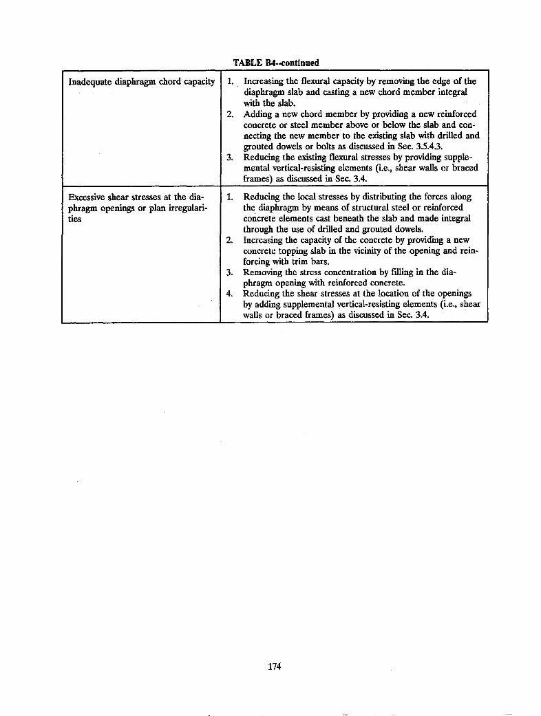
TABLE B4--continued
Inadequate diaphragm chord capacity 1. Increasing the flexural capacity by removing the edge of thediaphragm slab and casting a new chord member integralwith the slab.
2. Adding a new chord member by providing a new reinforcedconcrete or steel member above or below the slab and con-necting the new member to the existing slab with drilled andgrouted dowels or bolts as discussed in Sec. 3.5.4.3.
3. Reducing the existing flexural stresses by providing supple-mental vertical-resisting elements (i.e., shear walls or bracedframes) as discussed in Sec. 3.4.
Excessive shear stresses at the dia- 1. Reducing the local stresses by distributing the forces alongphragm openings or plan irregulari- the diaphragm by means of structural steel or reinforcedties concrete elements cast beneath the slab and made integral
through the use of drilled and grouted dowels.2. Increasing the capacity of the concrete by providing a new
concrete topping slab in the vicinity of the opening and rein-forcing with trim bars.
3. Removing the stress concentration by filling in the dia-phragm opening with reinforced concrete.
4. Reducing the shear stresses at the location of the openingsby adding supplemental vertical-resisting elements (i.e., shearwalls or braced frames) as discussed in Sec. 3.4.
174

TABLE B4--continued
POURED GYPSUM DIAPHRAGMS
Inadequate in-plane shear capacity ofthe concrete diaphragm
Inadequate diaphragm chord capacity
Excessive shear stresses at the dia-phragm openings or plan irregulari-ties
1. Increasing the shear capacity by overlaying the existing con-crete diaphragm with a new reinforced concrete topping slab.
2. Reducing the shear in the existing concrete diaphragm byproviding supplemental vertical-resisting elements (i.e., shearwalls or braced frames) as discussed in Sec. 3.4.
3. Increasing the flexural capacity by removing the edge of thediaphragm slab and casting a new chord member integralwith the slab.
4. Adding a new chord member by providing a new reinforcedconcrete or steel member above or below the slab and con-necting the new member to the existing slab with drilled andgrouted dowels or bolts as discussed in Sec. 3.5.4.3.
5. Reducing the existing flexural stresses by providing supple-mental vertical-resisting elements (i.e., shear walls or bracedframes) as discussed in Sec. 3.4.
6. Reducing the local stresses by distributing the forces alongthe diaphragm by means of structural steel or reinforcedconcrete elements cast beneath the slab and made integralthrough the use of drilled and grouted dowels.
7. Increasing the capacity of the concrete by providing a newconcrete topping slab in the vicinity of the opening and rein-forcing with trim bars.
8. Removing the stress concentration by filling in the dia-phragm opening with reinforced concrete.
9. Reducing the shear stresses at the location of the openingsby adding supplemental vertical-resisting elements (i.e., shearwalls or braced frames) as discussed in Sec. 3.4.
10. Adding a new horizontal bracing system may be the mosteffective strengthening alternative.
PRECAST CONCRETE DIAPHRAGMS(precast or post-tensioned concrete planks, tees, or cored slabs)
Inadequate in-plane shear capacity of 1. Replacing and increasing the capacity of the existing connec-the connections between the adjacent tions by overlaying the existing diaphragm with a new rein-units forced concrete topping slab.
2. Reducing the shear forces on the diaphragm by providingsupplemental vertical-resisting elements (i.e., shear walls orbraced frames) as discussed in Sec. 3.4.
Inadequate diaphragm chord capacity 1. Providing a new continuous steel member above or belowthe steel slab and connecting the new member to the existingslab with bolts.
2. Removing the edge of the diaphragm and casting a newchord member integral with the slab.
3. Reducing the diaphragm chord forces by providing supple-mental vertical-resisting elements (i.e., shear walls or bracedframes) as discussed in Sec. 3.4.
175

TABLE B4--continued
PRECAST CONCRETE DLAPHRAGMS--continued
Excessive in-plane shear stresses atdiaphragm openings or plan irreg-ularities
______________________________________________ &
1. Reducing the local stresses by distributing the forces along
the diaphragm by means of concrete drag struts cast beneaththe slab and made integral with the existing slab with drilled
and grouted dowels.2. Increasing the capacity by overlaying the existing slab with a
new reinforced concrete topping slab with reinforcing trimbars in the vicinity of the opening.
3. Removing the stress concentration by filling in the dia-phragm opening with reinforced concrete.
4. Reducing the shear stresses at the location of the openingsby providing supplemental vertical-resisting elements (i.e.,shear walls or braced frames) as discussed in Sec. 3.4.
STEEL DECK DIAPHRAGMS(steel decking on steel framing)
Inadequate in-plane shear capacity 1. Increasing the steel deck shear capacity by providing addi-
which may be governed by the capac- tional welding.
ity of the welding to the supports or 2. Increasing the deck shear capacity of unfilled steel decks by
the capacity of the seam welds be- adding a reinforced concrete fill or overlaying with concrete
tween the deck units filled steel decks a new topping slab.3. Increasing the diaphragm shear capacity by providing a new
horizontal steel bracing system under the existing diaphragm.
4. Reducing the diaphragm shear stresses by providing supple-mental vertical-resisting elements to reduce the diaphragmspan as discussed in Sec. 3.4.
Inadequate diaphragm chord capacity 1. Increasing the chord capacity by providing welded or boltedcontinuity splices in the perimeter chord steel framing mem-bers.
2. Increasing the chord capacity by providing a new continuoussteel member on top or bottom of the diaphragm.
3. Reducing the diaphragm chord stresses by providing supple-mental vertical-resisting elements (i.e., shear walls or bracedframes) such that the diaphragm span is reduced as dis-cussed in Sec. 3.4.
Excessive in-plane shear stresses at 1. Reducing the local stress concentrations by distributing the
diaphragm openings or plan irregu- forces into the diaphragm by means of steel drag struts.
larities 2. Increasing the capacity of the diaphragm by reinforcing theedge of the opening with a steel angle frame welded to thedecking.
3. Reducing the diaphragm stresses by providing supplementalvertical-resisting elements (i.e., shear walls, braced frames or
new moment frames) such that the diaphragm span is re-
duced as discussed in Sec. 3.4.
176

TABLE B4-continued
HORIZONTAL STEEL BRACING
Inadequate force capacity of themembers (i.e., bracing and floor orroof beams) and/or the connections
*1
1. Increasing the capacity of the existing bracing members orremoving and replacing them with new members and con-nections of greater capacity.
2. Increasing the capacity of the existing members by reducingunbraced lengths.
3. Increasing the capacity of the bracing system by adding newhorizontal bracing members to previously unbraced panels (iffeasible).
4. Increasing the capacity of the bracing system by adding asteel deck diaphragm to the floor system above the steelbracing.
5. Reducing the stresses in the horizontal bracing system byproviding supplemental vertical-resisting elements (i.e., shearwalls or braced frames) as discussed in Sec. 3.4.
177
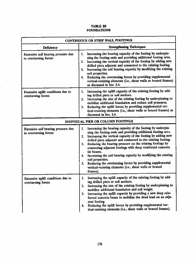
TABLE BSFOUNDATIONS
CONTINUOUS OR STRIP WALL FOOTINGS
Deficiency Strengthening Techniques
Excessive soil bearing pressure due 1. Increasing the bearing capacity of the footing by underpin-
to overturning forces ning the footing ends and providing additional footing area.2. Increasing the vertical capacity of the footing by adding new
drilled piers adjacent and connected to the existing footing.3. Increasing the soil bearing capacity by modifying the existing
soil properties.4. Reducing the overturning forces by providing supplemental
vertical-resisting elements (i.e., shear walls or braced frames)
as discussed in Sec. 3.4.
Excessive uplift conditions due to 1. Increasing the uplift capacity of the existing footing by add-
overturning forces ing drilled piers or soil anchors.2. Increasing the size of the existing footing by underpinning to
mobilize additional foundation and reduce soil pressures.3. Reducing the uplift forces by providing supplemental ver-
tical-resisting elements (i.e., shear walls or braced frames) asdiscussed in Sec. 3.4.
INDIVIDUAL PIER OR COLUMN FOOTINGS
Excessive soil bearing pressure due 1. Increasing the bearing capacity of the footing by underpin-
to overturning forces ning the footing ends and providing additional footing area.2. Increasing the vertical capacity of the footing by adding new
drilled piers adjacent and connected to the existing footing.3. Reducing the bearing pressure on the existing footings by
connecting adjacent footings with deep reinforced concretetie beams.
4. Increasing the soil bearing capacity by modifying the existingsoil properties.
5. Reducing the overturning forces by providing supplementalvertical-resisting elements (i.e., shear walls or bracedframes).
Excessive uplift conditions due tooverturning forces
1. Increasing the uplift capacity of the existing footing by add-ing drilled piers or soil anchors.
2. Increasing the size of the existing footing by underpinning tomobilize additional foundation and soil weight.
3. Increasing the uplift capacity by providing a new deep rein-forced concrete beam to mobilize the dead load on an adja-
cent footing.4. Reducing the uplift forces by providing supplemental ver-
tical-resisting elements (i.e., shear walls or braced frames).
178
I

TABLE BS--continued
INDIVIDUAL PIER OR COLUMN FOOTINGS--continued
Inadequate passive soil pressure to 1. Providing an increase in bearing area by underpinning andresist lateral loads enlarging the footing.
2. Providing an increase in bearing area by adding new tiebeams between existing footings.
3. Improving the existing soil conditions adjacent to the footingto increase the allowable passive pressure.
4. Reducing the bearing pressure at overstressed locations byproviding supplemental vertical-resisting elements such asshear walls or braced frames as discussed in Sec. 3.4.
PILES OR DRILLED PIERS
Excessive tensile or compressive 1. Increasing the capacity of the foundation by removing theloads on the piles or piers due to the existing pile cap, driving additional piles and providing newseismic forces combined with the pile caps of larger size.gravity loads 2. Reducing the loads on overstressed pile caps by adding tie
beams to adjacent pile caps and distributing the loads.
Inadequate lateral force capacity to 1. Reducing the loads on overstressed pile caps by adding tietransfer the seismic shears from the beams to adjacent pile caps and distributing the loads.pile caps and the piles to the soil 2. Increasing the allowable passive pressure of the soil by im-
proving the soil adjacent to the pile cap.3. Increasing the capacity of the foundation by removing the
existing pile cap, driving additional piles, and providing newpile caps of larger size.
4. Reducing loads on the piles or piers by providing supplemen-tal vertical-resisting elements (i.e., braced frames or shearwalls) and transferring forces to other foundation memberswith reserve capacity as discussed in Sec. 3.4.
MAT
Inadequate moment capacity to resist 1. Increasing the mat capacity locally by providing additionalcombined gravity plus seismic over- reinforced concrete (i.e., an inverted column capital) doweledturning forces and bonded to the existing mat to act as a monolithic sec-
tion.2. Providing new shear walls above the mat to distribute the
overturning loads and also to locally increase the sectionmodulus of the mat.
Inadequate passive soil pressure to 1. Constructing properly spaced shear keys at the mat perime-resist sliding ter.
179

TABLE B6
DIAPHRAGM TO VERTICAL ELEMENT CONNECTIONS
180
CONNECTIONS OF TIMBER DIAPHRAGMS
Deficiency Strengthening Techniques
Inadequate capacity to transfer 1. Increasing the shear transfer capacity of the diaphragm local
in-plane shear at the connection of to the connection by providing additional nailing to existing
the diaphragm to interior shear walls or new blocking.or vertical bracing 2. Reducing the local shear transfer stresses by distributing the
forces from the diaphragm by providing a collector memberto transfer the diaphragm forces to the shear wall.
3. Reducing the shear transfer stress in the existing connectionby providing supplemental vertical-resisting elements as dis-cussed in Sec. 3.4.
Inadequate capacity to transfer 1. Increasing the capacity of existing connections by providing
in-plane shear at the connection of additional nailing and/or bolting.
the diaphragm to exterior shear walls 2. Reducing the local shear transfer stresses by distributing the
or vertical bracing forces from the diaphragm by providing chords or collectormembers to collect and distribute shear from the diaphragmto the shear wall or bracing.
3. Reducing the shear stress in the existing connection by pro-viding supplemental vertical-resisting elements as discussedin Sec. 3.4.
Inadequate out-of-plane anchorage at 1. Increasing the capacity of the connection by providing steel
the connection of the diaphragm to straps connected to the wall (using drilled and grouted bolts
exterior concrete or masonry walls or through bolts for masonry walls) and bolted or lagged tothe diaphragm or roof or floor joists.
2. Increasing the capacity of the connections by providing asteel anchor to connect the roof or floor joists to the walls.
3. Increasing the redundancy of the connection by providingcontinuity ties into the diaphragm.
Inadequate tensile capacity between 1. Increasing the tensile capacity of the connections at the edge
floors due to overturning moments of the shear walls by providing metal connectors.2. Reducing the overturning moments by providing supplemen-
tal vertical-resisting elements as discussed in Sec. 3A.

TABLE B6--continued
CONNECTIONS OF CONCRETE DIAPHRAGMS
Inadequate in-plane shear transfer 1. Reducing the local stresses at the diaphragm-to-wall inter-capacity face by providing collector members or drag struts under the
diaphragm and connecting them to the diaphragm and thewall.
2. Increasing the capacity of the existing diaphragm-to-wallconnection by providing additional dowels grouted intodrilled holes.
3. Reducing the shear stresses in the existing connection byproviding supplemental vertical-resisting elements as dis-cussed in Sec. 3.4.
Inadequate anchorage capacity for 1. Increasing the capacity of the connection by providing addi-out-of-plane forces in the connecting tional dowels grouted into drilled holes.walls 2. Increasing the capacity of the connection by providing a new
member above or below the slab connected to the slab withdrilled and grouted bolts similar to that for providing a newdiaphragm chord.
CONNECTIONS OF POURED GYPSUM DIAPHRAGMS
Inadequate in-plane shear transfer 1. Providing new dowels from the diaphragm into the shearwall.
2. Removing the gypsum diaphragm and replacing it with steeldecking.
Inadequate anchorage capacity for 3. Adding a new horizontal bracing system designed to resist allout-of-plane forces in the connecting of the seismic forces.walls
CONNECTIONS OF PRECAST CONCRETE DIAPHRAGMS
Inadequate in-plane shear transfer 1. Increasing the capacity of the connection by providing addi-capacity tional welded inserts or dowels placed in drilled or grouted
holes.2. Increasing the capacity of the connection by providing a
reinforced concrete overlay that is bonded to the precastInadequate anchorage capacity at the units and anchored to the wall with additional dowels placedexterior walls for out-of-plane forces in drilled and grouted holes.
3. Reducing the forces at the connection by providing supple-mental vertical-resisting elements as discussed in Sec. 3.4.
181

TABLE B6--continued
CONNECTIONS OF STEEL DECK DIAPHRAGMS WITHOUT CONCRETE FILL
Inadequate in-plane shear capacity oranchorage capacity for out-of-planeforces in walls
_____________________________________________________________________________________I
1. Increasing the capacity of the connection by providing addi-tional welding at the vertical element.
2. Increasing the capacity of the connection by providing addi-tional anchor bolts.
3. Increasing the capacity of the connection by providing con-crete fill over the deck with dowels grouted into holes drilledinto the wall.
4. Increasing the capacity of the connection by providing newsteel members to effect a direct transfer of diaphragm shearsto a shear wall.
5. Reducing the local stresses by providing additional vertical-resisting elements such as shear walls, braced frames, ormoment frames as discussed in Sec. 3.4.
CONNECTIONS OF STEEL DECK DIAPHRAGMS WITH CONCRETE FILL
Inadequate in-plane shear capacity or 1. Increasing the shear capacity by drilling holes through theanchorage capacity for out-of-plane concrete fill, and providing additional shear studs welded toforces in walls the vertical elements through the decking.
2. Increasing the capacity of the connection by providing addi-tional anchor bolts (drilled and grouted) connecting the steelsupport to the wall.
3. Increasing the capacity of the connection by placing dowelsbetween the existing wall and diaphragm slab.
4. Reducing the local stresses by providing additional vertical-resisting elements such as shear walls, braced frames, ormoment frames as discussed in Sec. 3.4.
CONNECTIONS OF HORIZONTAL STEEL BRACING
Inadequate in-plane shear transfer 1. Increasing the capacity by providing larger or more bolts orcapacity by welding.
2. Reducing the stresses by providing supplemental vertical-resisting elements such as shear walls or braced frames asdiscussed in Sec. 3.4.
Inadequate anchorage capacity when 1. Increasing the capacity of the connection by providing addi-
supporting concrete or masonry walls tional anchor bolts grouted in drilled holes and by providing
for out-of-plane forces more bolts or welding to the bracing members.
182

TABLE B7VERTICAL ELEMENT TO FOUNDATION CONNECTIONS
CONNECTIONS OF WOOD STUD SHEAR WALLS
Deficiency Strengthening Techniques
Inadequate shear capacity of the 1. Increasing the shear capacity by providing new or additionalanchorage anchor bolts between the sill plate and the foundation.
2. Increasing the shear capacity by providing steel angles orplates with anchor bolts connecting them to the foundationand bolts or lag screws connecting them to the sill plate orwall.
Inadequate shear capacity of cripple 1. Adding plywood sheathing over the cripple studs (usually onstud walls the inside) by nailing into the floor framing and the sill plate.
Anchorage of the sill plate to the foundation also must beprovided.
Inadequate uplift capacity 1. Increasing the capacity by providing steel hold-downs boltedto the wall and anchored to the concrete.
2. Reducing the uplift requirement by providing supplementalshear walls as discussed in Sec. 3.4.
CONNECTIONS OF METAL STUD SHEAR WALLS
Inadequate shear capacity of the 1. Provide anchor bolts, grouted in drilled holes, through sillanchorage plate of wall.
2. Provide steel angles with anchor bolts to concrete and boltsor screws to wall.
Inadequate shear capacity of cripple 1. Provide plywood sheathing, nailing into cripple studs, sillstud walls plate, and first floor framing; anchor sill plate to foundation.
Inadequate uplift capacity 1. Provide steel hold-down with bolts or screws to wall andanchor bolts to concrete at ends of shear wall.
2. Provide additional shear walls or vertical bracing.
CONNECTIONS OF PRECAST CONCRETE SHEAR WALLS
Inadequate capacity to resist in-planeor out-of-plane shear forces
1. Increasing the capacity of the connection by providing a newsteel member connecting the wall to the foundation or theground floor slab.
2. Increasing the capacity of the connection by adding a newthickness of concrete (either cast-in-place or shotcrete)placed against the precast wall doweling into the existingfoundation or ground floor slab.
183

TABLE B7-continued
CONNECTIONS OF PRECAST CONCRETE SHEAR WALLS--continued
184
Inadequate hold-down capacity to 1. Increase the hold-down capacity by removing concrete at the
resist seismic overturning forces edge of the precast unit to expose the reinforcement provide,new drilled and grouted dowels into the foundation, andpour a new concrete pilaster.
2. Reduce the uplift forces by providing supplemental vertical-resisting elements such as shear walls or braced frames asdiscussed in Sec. 3.4.
CONNECTIONS OF BRACED FRAMES
Inadequate shear capacity 1. Increasing the capacity by providing new steel memberswelded to the braced frame base plates and anchored to theslab or foundation with drilled and grouted anchor bolts.
2. Reducing the shear loads by providing supplemental steelbraced frames as discussed in Sec. 3.4.
Inadequate uplift resistance 1. Increasing the capacity by providing new steel memberswelded to the base plate and anchored to the existing foun-dation.
2. Reducing the uplift loads by providing supplemental steelbraced frames as discussed in Sec. 3.4.
CONNECTIONS OF STEEL MOMENT FRAMES
Inadequate shear capacity 1. Increasing the shear capacity by providing steel shear lugswelded to the base plate and embedded in the foundation.
2. Increasing the shear and tensile capacity by installing addi-Inadequate flexural capacity tional anchor bolts into the foundation.
3. Increasing the shear capacity by embedding the column in a
Inadequate uplift capacity reinforced concrete pedestal that is bonded or embeddedinto the existing slab or foundation.

APPENDIX C
REHABILITATION EXAMPLES*
Two examples are included in this appendix to demonstrate the process of selecting appropriate seismic rehabili-tation techniques: a two-story steel frame building and a two story unreinforced masonry building. Bothbuildings were evaluated to determine their seismic deficiencies in accordance with the NEHRP Handbookforthe Seismic Evaluation of Existing Buildings (which includes the evaluations as Examples D1 and D6 in AppendixD).
C1 T'WO-STORY STEEL FRAME BUILDING EXAMPLE
C1.1 DESCRIPTION OF BUILDING
The building is 200 ft by 340 ft in plan with 20 ft by 20 ft bays. The girders in the transverse direction areconnected to the column flanges with top and bottom clip angles. The beams in the longitudinal direction areconnected to the column webs with beam web connections. The floor and roof diaphragms consists of steeldecking with concrete fill.
C1.2 DEFICIENCIES
Inadequate moment capacity in both directions.
C13 STRENGTHENING ALTERNATIVES
This building could be strengthened by providing adequate moment capacity to the existing frames, by providingnew diagonal bracing, and/or by providing new shear walls
C13.1 Providing Adequate Moment Capacity
Assuming that the first story shear of 2,970 kips can be equally distributed to all columns, it is calculated thatthere is excess capacity for the columns in the transverse direction (i.e., the strong axis of the columns) butgrossly inadequate capacity for the columns in the longitudinal direction (i.e., the weak axis of the columns).This indicates that it is not feasible to develop adequate frame action to resist the seismic forces in thelongitudinal direction, but it is feasible in the transverse direction. The structural modifications (Figure C1.3.1)required to develop moment frame action will involve:
1. Removal of the concrete fill and steel decking over the ends of the transverse girders at the columns. (Itis assumed that the steel decking is supported on secondary floor beams that frame into the transverseframe girders so that there are no adverse effects associated with removal of the decking over top flangesof these girders adjacent to the columns.)
The American Iron and Steel Institute has written a minority opinion concerning this appendix; see page193.
185

2. Addition of new vertical shear connections between the girder webs and the column flanges.
3. Removal of existing clip angles at the top and bottom flanges of the girders.
4. Addition of new moment plates welded at the top and bottom flanges of the girders.
FIGURE C1.3.1 Providing moment capacity to an existing steel frame.
The design of these modifications should provide moment plates that are sized so as to yield prior to
inducing yield stress in the columns. The new girder web shear connections should be sized for the gravity load
shears (i.e., dead and live load) plus the shears associated with the formation of yield hinges in the moment
plates. The column section of the new frame joint must be checked to determine the possible need for
horizontal stiffeners opposite the girder flanges. The column web also should be checked to determine the need
for doubler plates. Stiffeners probably can be fitted above or below the existing longitudinal beam-, at the
column, but if doubler plates are required, this alternative may not be feasible because of interference with the
exsting longitudinal beam connection.
C1.3.2 Providing New Diagonal Bracing
Assume that diagonal bracing is to be considered for the longitudinal direction of the building. If the existing
diaphragms have adequate capacity, the new bracing can be located in the exterior walls to avoid possible inter-
ference with the internal circulation within the building. If the diaphragm has inadequate capacity to transfer
186
(E) transverse0 _ =girder
(N) web shearconnection
(E) clip angles, to beremoved.\ removed (E) longitudinal
beamSECTION a-a
(E) transverse girder (N) moment plate
(E) longitudinal Remove (E) concretebeam fill and steel decking
PLAN
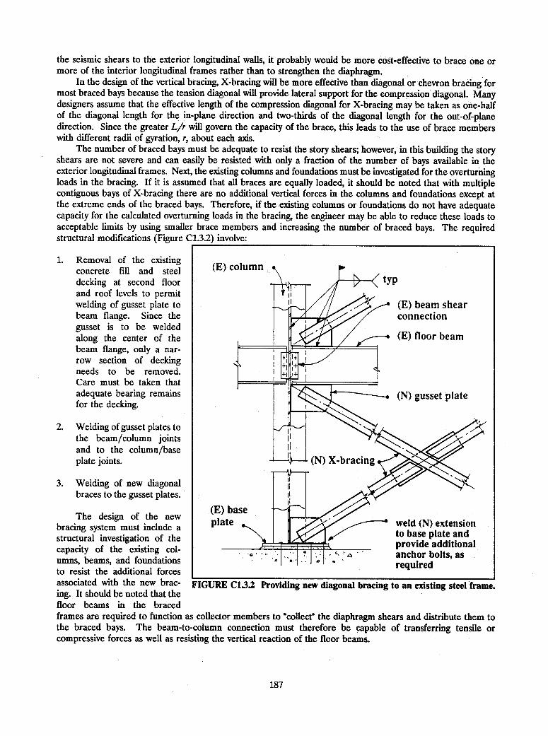
the seismic shears to the exterior longitudinal walls, it probably would be more cost-effective to brace one ormore of the interior longitudinal frames rather than to strengthen the diaphragm.
In the design of the vertical bracing, X-bracing will be more effective than diagonal or chevron bracing formost braced bays because the tension diagonal will provide lateral support for the compression diagonal. Manydesigners assume that the effective length of the compression diagonal for X-bracing may be taken as one-halfof the diagonal length for the in-plane direction and two-thirds of the diagonal length for the out-of-planedirection. Since the greater Lir will govern the capacity of the brace, this leads to the use of brace memberswith different radii of gyration, r, about each axis.
The number of braced bays must be adequate to resist the story shears; however, in this building the storyshears are not severe and can easily be resisted with only a fraction of the number of bays available in theexterior longitudinal frames. Next, the existing columns and foundations must be investigated for the overturningloads in the bracing. If it is assumed that all braces are equally loaded, it should be noted that with multiplecontiguous bays of X-bracing there are no additional vertical forces in the columns and foundations except atthe extreme ends of the braced bays. Therefore, if the existing columns or foundations do not have adequatecapacity for the calculated overturning loads in the bracing, the engineer may be able to reduce these loads toacceptable limits by using smaller brace members and increasing the number of braced bays. The requiredstructural modifications (Figure C1.3.2) involve:
1. Removal of the existingconcrete fill and steel (E) columndecking at second floor VPand roof levels to permitwelding of gusset plate to (E) beam shearbeam flange. Since the connectiongusset is to be weldedalong the center of the (E) floor beambeam flange, only a nar-row section of deckingneeds to be removed.Care must be taken thatadequate bearing remains (N) gusset platefor the decking.
2. Welding of gusset plates tothe beam/column jointsand to the column/base ing plate joints. (N) X-bracing
3. Welding of new diagonalbraces to the gusset plates.
The design of the new plate w A' e nbracing system must include a platebw e ()te nsionstructural investigation of the to base plate adof the existing I ~~~~~~~~provide additionalcapacity of the existing co- ' anchor bolts, asumns, beams, and foundations A v J ' requiredto resist the additional forcesassociated with the new brac- FIGURE C1.3.2 Providing new diagonal bracing to an existing steel frame.ing. It should be noted that thefloor beams in the bracedframes are required to function as collector members to "collect" the diaphragm shears and distribute them tothe braced bays. The beam-to-column connection must therefore be capable of transferring tensile orcompressive forces as well as resisting the vertical reaction of the floor beams.
187

C133 Providing New Shear Walls
New shear walls of reinforced concrete or reinforced masonry may be provided in lieu of bracing or frame actionin either direction of the building. If shear walls are provided, they should be infilled bays on a column line andpreferably in a location where window or door openings are not required. With infill walls, the columns canfunction as boundary members for overturning loads and the beams or girders as collector members for the shearwalls. The shear walls probably will require new foundations and also will add significantly to the building mass,which will increase the seismic story shears.
CIA RELATIVE MERITS OF THE ALTERNATIVE STRENGTHENING TECHNIQUES
As indicated above, the frame columns have inadequate capacity to resist the seismic story shears in thelongitudinal direction; therefore, new vertical bracing or shear walls are the available options. It appears thatthe bracing could be installed in the exterior longitudinal frames without strengthening the columns or thefoundations whereas the shear walls probably would need new foundations and be more disruptive as well asrequiring more time for construction.
In the transverse direction, providing moment capacity to the existing frames (Figure C1.3.1) appears to befeasible. It appears that this would be required for about two-thirds of the frames in the transverse directionat the second floor level and only about one-half of the frames at the roof level.
Preliminary design of the structural strengthening concepts should be performed to define the location andextent of the modifications and to size the new structural members. Relative costs for the various alternativesalso should be developed and attention should be given to the other considerations described at the beginningof Chapter 3. With this information, the most appropriate seismic strengthening technique for the building canbe selected.
C2 UNREINFORCED MASONRY BUILDING EXAMPLE
C2.1 DESCRIPFTION OF BUILDING
This building is a two-story structure, 30 ft by 100 ft in plan. The first level has an open front at the east endand a longitudinal bearing wall on the centerline of the building. There are no crosswalls in the first level, butthe second level contains apartments with many crosswalls. The roof diaphragm is constructed of diagonaltimber sheathing. The floor contains finished wood flooring over timber diagonal sheathing. The existingconditions are shown in Figure C2.1.
C22 DEFICIENCIES
The building's deficiencies involve:
1. Torsion--The east end of the building has negligible resistance to lateral loads at the first level and consti-tutes a severe seismic hazard.
2. Adjacent Building--The adjacent building on the south side is not separated from the south wall and wouldact as a buttress for the diaphragms of the subject building. This could result in damage to both buildings.
3. Wall Stability--The gabled east and west walls at the second level are too slender (i.e., 9 in.) for thecalculated out-of-plane seismic response imparted by the roof diaphragm.
4. Wall Anchorage--There is a serious inadequacy in the anchorage of all walls to the floor and roof dia-phragms.
188

5. In-Plane Shear Strength of Walls--In addition to the obvious deficiency in the open east wall at the firstlevel, there also are potential deficiencies in the remaining east and west walls at both levels.
6. Parapet--The 9-in. unreinforced masonry walls in the second level terminate in an unsupported 18-in. highparapet above the roof level that may be a hazard to life safety in a severe earthquake.
SECOND LEVEL'-. 13-inch masonryexterior walls
9-inch masonrypartition
Ii.
I,
A._;
FIRST LEVEL
FIGURE C2.1 Exdsting two-story unreinforced masonry building.
C23 STRENGTHENING TECHNIQUES
The structural evaluation of this building was conducted using the ABK Methodology for unreinforced masonrybracing wall buildings with wood diaphragms. The recommended strengthening techniques (Figure C2.3) alsofollow that methodology.
C23.1 Torsion
The east wall of the building is deficient in both strength and stiffness. In addition, extensive wall anchors arerequired at both the first and second levels. Although the open front condition at the first level could beimproved with either a concrete or steel moment frame, the extensive additional work required for this wall andits foundation combine to make replacement an attractive alternative.
189
fN
U'.
: t-

Replacement of the existing east wall with a two-story reinforced concrete frame is the recommendedstrengthening alternative. Since the roof and second floor joists are supported on the longitudinal walls, shoringwill not be required as the east wall is removed. Temporary lateral bracing in the north-south direction should
-___________________ _ be utilized during the replace-ment of the east wall. The new
(N) 4-inchl reinforced n (N) wall anchorages second level wall would be aconcrete overlay at second and roof metal stud wall with windowon (E) wall levels e openings similar to the existing
on (E) wall o-~. levels @> ones and with brick veneer toI[II fill I I1 I match the other brick walls, if
F~~ --JN-Y Ndesired.
]LILir I iLL__ iLa I[(N) reinforced concrete |frame with brick veneer>/on steel studs --
SECOND LEVEL
(N) plywood sheathedcrosswalls ,-*
reinforced concreteshear wall
FIRST LEVEL
FIGURE C2.3 Proposed structural modifications.
C2.3.2 Adjacent Building
The proposed solution to theproblem with the adjacentbuilding is to provide a newreinforced concrete shear wallin the first level of the subjectbuilding. The wall would be inline with the west wall of theadjacent building. In additionto the new shear wall, threenew timber cross walls will beprovided in the first level (Fig-ure C2.3) to reduce the dia-phragm deflection. The shearwall, the cross walls, and theirconnections to the floor dia-phragm will be designed inaccordance with the ABKMethodology. This strengthen-ing may not completely solvethe adjacent building problem,but the new shear wall and thecross walls will significantlyreduce the inertia forces trans-mitted to the adjacent building.
(N) reinforcedconcrete frame .
C233 Wall Stability
The height to thickness ratio, h/t, of an unreinforced masonry wall is used as an index of the stability of the wallfor the out-of-plane seismic response induced by the diaphragm. The east wall is to be replaced with areinforced concrete wall so that the west wall in the second level is the only remaining wall with an excessive h/tratio. The deficiency can be corrected by providing anchors at the ceiling level and bracing this anchorage upto the wood diaphragm or by designing vertical wall braces that span from the floor to the roof anchorage level.
190
I
C23A Wall Anchorage
All anchorages of masonry walls to diaphragms were found to be inadequate at both levels of the building.Supplementary anchors must be provided for the calculated anchorage. The anchors should be similar to thoseindicated in Figure 3.7.1.4a or b. Significantly greater allowable loads are permitted for anchors that extendthrough the masonry wall with a large metal washer on the outside of the wall. This type of anchor should beused in all locations where access is available to the outside face of the wall.
C2.3.5 In-Plane Shear Stress
The new reinforced concrete frame at the east wall, the new shear wall, and the new concrete overlay for thewest wall at second level have eliminated the calculated in-plane overstress in the east and west walls.
C2.3.6 Parapet
The unreinforced and unbraced paraet is a life safety hazard because of its h/t ratio. It is recommended thatthe parapet be reduced in height by the removal of several courses of brick (i.e., 8 to 10 in.). This should bepreceded by a horizontal saw cut at a mortar joint on both sides of the wall to avoid damage to the remainingbrickwork. The top of the reduced parapet then should be sealed with a mortar cap to prevent intrusions ofmoisture into the wall.
191

MINORITY OPINIONS
The comments concerning this handbook presented below are included at the request of the representative ofthe American Iron and Steel Institute.
• Concerning Chapter 1, Sec. 1.4:
It is questioned if rehabilitation techniques need to be fully consistent with the NEHRPRecommended Provisions for new buildings. The NEHRP Recommended Provisions weredeveloped with modern buildings as the underlying basis. Force fitting detailing provisionsdeveloped for modern structures onto older structures may overlook adequate details builtinto many older buildings which can provide adequate toughness.
* Concerning Chapter 3, Sec. 3.0.4:
In the 5th line of the first paragraph the word "tested" should be changed. A test impliesthat a structural system has been subjected to known loading conditions which is typically notthe case with existing buildings.
* Concerning Chapter 3, Sec. 3.1:
We strongly object to the organization of this section. Typically when several subjects arepresented the most significant is placed first. Since we are dealing with techniques of rehab-ilitating seismically deficient structures this section should be organized with the mostsignificant (deficient) structures first. The scope of the section should then explain thereason for the organization of the section. For whatever reason this section has beenorganized with steel moment frames placed first. Steel moment frames have been observedto be one of the most reliable seismic resisting systems worldwide, the majority of whichwere not designed to modern seismic detailing practices.
* Concerning Chapter 4, Sec. 4.1:
Additional techniques such as reducing the weight by eliminating hollow clay tile partitionsand substituting with lightweight partitions should be included.
* Concerning Appendix C:
Where a limited number of examples are to be presented they should be based upon thehighest risk structural systems. Certainly steel moment frames do not fall into that category.The two most common types of seismically deficient structural systems observed in pastearthquakes are unreinforced masonry and poorly detailed concrete frames. The inclusionof steel moment frames as one of two examples does not serve justice to the potential riskof the various structural systems.
The comments concerning this handbook presented below are included at the request of the representative ofthe American Institute of Steel Construction:
* Concerning Chapter 3:
In Sec. 3.1.1.1, modify the first sentence to read: "The principal deficiencies of ordinary steelmoment frames in high seismic areas are:"
193

In Sec. 3.3.1.1, modify the first sentence to read: 'The principal deficiencies of steel
concentrically braced frames in high seismic areas are:"
Users of this document may not read the Introduction and/or Sec. 3.0.4 for a proper
orientation on seismic zonation.- Thus, explicit reminders in the actual design chapters are
needed.
194

BUILDING SEISMIC SAFETY COUNCILBOARD OF DIREMION -- 1992
Chairman Gerald H. Jones, Director of Codes Administration, Kansas City, Missouri
Vice Chairman Allan Porush, Dames and Moore, Los Angeles, California (representing Structural EngineersAssociation of California)
Secretary Harry W. Martin, American Iron and Steel Institute, Newcastle, California
Ex-Officio Warner Howe, Gardner and Howe, Memphis, Tennessee
Members John C. Canestro, PE, City of Orinda, Pleasanton, California (representing the NationalInstitute of Building Sciences)
S. K. Ghosh, Portland Cement Association, Skokie, Illinois
Mark B. Hogan, National Concrete Masonry Association, Herndon, Virginia
Nestor Iwankiw, American Institute of Steel Construction, Chicago, Illinois
H. S. "Pete" Kellam, Graham and Kellam, San Francisco, California (representing theAmerican Society of Civil Engineers)
Les Murphy, International Association of Fire Fighters, (representing AFL/CIO Building andConstruction Trades Department)
F. Robert Preece, Preece/Goudie & Associates, San Francisco, California, (representingEarthquake Engineering Research Institute
Blair Tulloch, Tulloch Construction, Inc., Oakland, California (representing the AssociatedGeneral Contractors of America)
David Tyree, National Forest Products Association, Georgetown, California
Martin Walsh, City of St. Louis, Missouri (representing the Building Officials and CodeAdministrators International)
Richard Wright, National Institute of Standards and Technology, Gaithersburg, Maryland(representing the Interagency Committee for Seismic Safety in Construction)
Staff James R. Smith, Executive Director0. Allen Israelsen, Project ManagerClaret M. Heider, Technical Writer-EditorKaren E. Smith, Administrative Assistant
195

BSSC MEMBER ORGANIZATIONS
AFL-CIO Building and Construction TradesDepartment
AISC Marketing, Inc.American Concrete InstituteAmerican Consulting Engineers CouncilAmerican Institute of ArchitectsAmerican Institute of Steel ConstructionAmerican Insurance Services Group, Inc.American Iron and Steel InstituteAmerican Plywood AssociationAmerican Society of Civil EngineersApplied Technology CouncilAssociated General Contractors of AmericaAssociation of Engineering GeologistsAssociation of Major City Building OfficialsBay Area Structural, Inc.Brick Institute of AmericaBuilding Officials and Code Administrators
InternationalBuilding Owners and Managers Association
InternationalBuilding Technology, IncorporatedCalifornia Geotechnical Engineers AssociationCanadian National Committee on Earthquake
EngineeringConcrete Masonry Association of California and
NevadaConcrete Reinforcing Steel InstituteEarthquake Engineering Research InstituteGeneral Reinsurance Corporation*Interagency Committee on Seismic Safety in
ConstructionInternational Conference of Building OfficialsMasonry Institute of AmericaMetal Building Manufacturers Association
National Association of Home BuildersNational Concrete Masonry AssociationNational Conference of States on Building Codes and
StandardsNational Elevator Industry, Inc.National Fire Sprinkler AssociationNational Forest Products AssociationNational Institute of Building SciencesNational Ready Mixed Concrete AssociationPermanent Commission for Structural Safety of
Buildings'Portland Cement AssociationPrecast/Prestressed Concrete InstituteRack Manufacturers InstituteSeismic Safety Commission (California)Southern Building Code Congress InternationalSteel Deck Institute, Inc.Steel Joist Institute*Steven Winter Associates, Inc.Structural Engineers Association of ArizonaStructural Engineers Association of CaliforniaStructural Engineers Association of Central
CaliforniaStructural Engineers Association of IllinoisStructural Engineers Association of Northern CaliforniaStructural Engineers Association of OregonStructural Engineers Association of San DiegoStructural Engineers Association of Southern CaliforniaStructural Engineers Association of UtahStructural Engineers Association of WashingtonThe Masonry SocietyWestern States Clay Products AssociationWestern States Council Structural Engineers
AssociationWestinghouse Electric Corporation
'Affiliate (non-voting) members.
197
* U.S. G.P.O. 1999 -722-072 / 94347