seismic design considerations for precast concrete ... · provisions which control the design -+,...
TRANSCRIPT

Robert E. Englekirk Ph.D., P.E. Adjunct Professor Department of Civil Engineering University of California at Los Angeles; and Chief Executive Officer Englekirk & Hart, Inc. Los Angeles, California
The precast concrete industry is perceived by the author to be at a crossroads - one path leading to an uncertain future, the other to a new industry with ever-expanding horizons. The evolution of the precast concrete industry in seismically active regions of the United States and other parts of the world are discussed. Current innovative system concepts are presented and the technological needs of the industry are identified. A program for insuring that the industry expands its horizons is outlined.
40
Seismic Design Considerations for Precast Concrete Multistory Buildings
Twenty-five years ago, the use of precast concrete in buildings located in regions of high seis
micity was more prevalent than it is today. (Reasons for this decline, together with ideas to alleviate this situation, are given in Refs. 1 and 2.)
Currently, most precast concrete used in buildings in high seismic zones, particularly on the West Coast, is confmed to: • Cladding • Topped floor slab systems
• Beams and girders (supporting nonseismic loads only)
• Columns (posts) Today, earthquake bracing systems
composed of precast concrete elements are seldom attempted. This exclusion of precast concrete elements from seismic load paths has not always been the case. In the early 1970s, a few precast concrete bracing systems were attempted. Two basic building systems were built: • Ductile frames using precast con-
CONCRETE COLUMN
Fig. 1. Precast concrete shell for a ductile frame beam.
PCI JOURNAL
POUR SOLID POCK AFTER WELDING
ANGLE 2X2X3/16 FIELD WELDED TO
GRO
w: r-
ET "'
BARS-1-
c
~
1-
Ill Ill Ill Ill :u lfl Ill Ill Ill Ill I I
=--
v
~ f:: ~'-r--- f5 I 16'
PANEL REINFORCING
I~
~ I 2-f5 I! BOTTOM OF PANEL
I UT~ t: :::: . . ..~ ... ~ , .. , . ... . .......
c~
(}
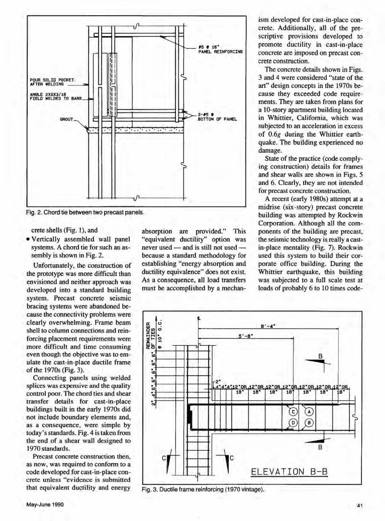
Fig. 2. Chord tie between two precast panels.
crete shells (Fig. 1), and • Vertically assembled wall panel
systems. A chord tie for such an assembly is shown in Fig. 2.
Unfortunately, the construction of the prototype was more difficult than envisioned and neither approach was developed into a standard building system. Precast concrete seismic bracing systems were abandoned be-
absorption are provided." This "equivalent ductility" option was never used - and is still not used -because a standard methodology for establishing "energy absorption and ductility equivalence" does not exist. As a consequence, all load transfers must be accomplished by a mechan-
u 0
ism developed for cast-in-place concrete. Additionally, all of the prescriptive provisions developed to promote ductility in cast-in-place concrete are imposed on precast concrete construction.
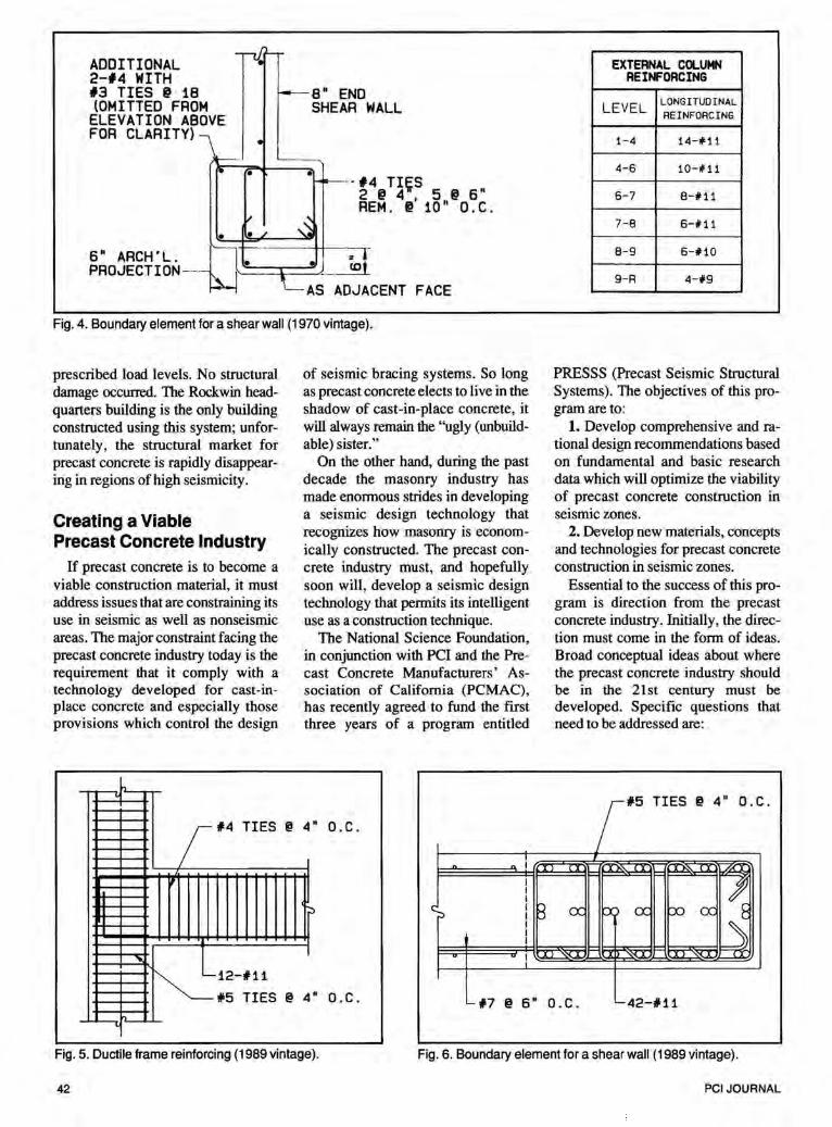
The concrete details shown in Figs. 3 and 4 were considered "state of the art" design concepts in the 1970s because they exceeded code requirements. They are taken from plans for a 10-story apartment building located in Whittier, California, which was subjected to an acceleration in excess of 0.6g during the Whittier earthquake. The building experienced no damage.
State of the practice (code complying construction) details for frames and shear walls are shown in Figs. 5 and 6. Clearly, they are not intended for precast concrete construction.
A recent (early 1980s) attempt at a midrise (six-story) precast concrete building was attempted by Rockwin Corporation. Although all the components of the building are precast, the seismic technology is really a castin-place mentality (Fig. 7). Rockwin used this system to build their corporate office building. During the Whittier earthquake, this building was subjected to a full scale test at loads of probably 6 to 10 times code-
B'-4'
cause the connectivity problems were clearly overwhelming. Frame beam shell to column connections and reinforcing placement requirements were more difficult and time consuming even though the objective was to emulate the cast-in-place ductile frame of the 1970s (Fig. 3).
a: ~Ul ZIIJ HH <1-::E 11.111.. a:o
. 5'-B' 0
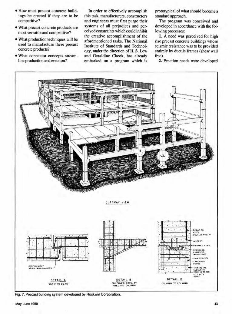
Connecting panels using welded splices was expensive and the quality control poor. The chord ties and shear transfer details for cast-in-place buildings built in the early 1970s did not include boundary elements and, as a consequence, were simple by today' s standards. Fig. 4 is taken from the end of a shear wall designed to 1970 standards.
Precast concrete construction then, as now, was required to conform to a code developed for cast-in-place concrete unless "evidence is submitted
. CD . CD . CD . CD . ., . C\1
.. Ill
ct 1--
'J....._r
8 I --,-
2' 4'4'4~12'0R .12'0R .12'0R .12' IR .12'0R .12"0R .1 "OR
1B" 18' 18' 18 18" 18' a· I
'0 '0 ~ fffJ ji) I
__.......J- I
lc 8
h.__ ELEVATION B-B -
that equivalent ductility and energy Fig. 3. Ductile frame reinforcing (1970 vintage).
May-June 1990 41
-ru. '-ADDITIONAL 2-#4 WITH #3 TIES @ 18 f---8" END (OMITTED FROM SHEAR WALL
ELEVATION ABOVE FOR CLARITY) •
r---r- • • ----#4 TI~S
2 @ 4 5 @ 6" REM . @' 10 " 0 . C .
" ~ • •L
6" ARCH'L. . = PROJECTION--· • _ ~ l ta {Jh- ::hl
\__AS ADJACENT FACE
Fig. 4. Boundary element for a shear wall (1970 vintage).
prescribed load levels. No structural damage occurred. The Rockwin headquarters building is the only building constructed using this system; unfortunately, the structural market for precast concrete is rapidly disappearing in regions of high seismicity.
Creating a Viable Precast Concrete Industry
If precast concrete is to become a viable construction material, it must address issues that are constraining its use in seismic as well as nonseismic areas. The major constraint facing the precast concrete industry today is the requirement that it comply with a technology developed for cast-inplace concrete and especially those provisions which control the design
-+,
of seismic bracing systems. So long as precast concrete elects to live in the shadow of cast-in-place concrete, it will always remain the ''ugly (unbuildable) sister."
On the other hand, during the past decade the masonry industry has made enormous strides in developing a seismic design technology that recognizes how masonry is economically constructed. The precast concrete industry must, and hopefully soon will, develop a seismic design technology that permits its intelligent use as a construction technique.
The National Science Foundation, in conjunction with PCI and the Precast Concrete Manufacturers' Association of California (PCMAC), has recently agreed to fund the first three years of a program entitled
rf4 TIES@ 4 • o.c.
";::>
"
EXTERNAL COLUMN REI~ORCING
LEVEL LONGITUDINAL REINFORCING
1-4 14-#11
4-6 10-#11
6-7 8-#11
7-8 6-#11
8-9 6-#10
9-R 4-#9
PRESSS (Precast Seismic Structural Systems). The objectives of this program are to:
1. Develop comprehensive and rational design recommendations based on fundamental and basic research data which will optimize the viability of precast concrete construction in seismic zones.
2. Develop new materials, concepts and technologies for precast concrete construction in seismic zones.
Essential to the success of this program is direction from the precast concrete industry. Initially, the direction must come in the form of ideas. Broad conceptual ideas about where the precast concrete industry should be in the 21st century must be developed. Specific questions that need to be addressed are:
15 TIES @ 4" O.C .
~12-#11 #5 TIES @ 4 • o.c. 17 @ 6" o.c. 42-111
- ~ fl-'-
Fig. 5. Ductile frame reinforcing (1989 vintage). Fig. 6. Boundary element for a shear wall (1989 vintage).
42 PCI JOURNAL
• How must precast concrete buildings be erected if they are to be competitive?
• What precast concrete products are most versatile and competitive?
• What production techniques will be used to manufacture these precast concrete products?
• What connector concepts streamline production and erection?
I·
CONFINEMENT ANGLE WITH ANCHORS
DETAIL A BEAM TO BEAM
In order to effectively accomplish this task, manufacturers, constructors and engineers must first purge their systems of all prejudices and perceived constraints which could inhibit the creative accomplishment of the aforementioned tasks. The National Institute of Standards and Technology, under the direction of H. S. Lew and Geraldine Cheok, has already embarked on a program which is
CUTAWAY VIEW
..
OETAI L B CONFINED AREA AT PRECAST COLUMN
Fig. 7. Precast building system developed by Rockwin Corporation.
May-June 1990
prototypical of what should become a standard approach.
The program was conceived and developed in accordance with the following processes:
1. A need was perceived for high rise precast concrete buildings whose seismic resistance was to be provided entirely by ductile frames (shear wall free).
2. Erection needs were developed
. ... . . ~ ...
• A·,
-!f+!'""-:.,.;jt~~- ~-.--. ':tttt· f"-1 N S ER T S
f~l: n~j··~· ~~·~~-- ~~+GROUTED JOINT r -STANDARD
tt-tt.,..· ·.-:-''tf:-:"""~h::tttt~ ~~~~~~~~ s .. :· tt-tt,:-..:-,~-'--..,1\'-.....;-tfii-'_ +-- SHIM AS REQ'D.
itft.~~~...:...;--ttlt:· ._____THREAOE 0 .. DOWEL
*lt:--""'--":-: . ..-,~':-ittt~ r-THIN METAL
-'--~-r----~· _• _. ,·,_ ~· ·-~· ~~~~~~VEE T~EBAR FILL WITH GR OUT
DETAIL C
COLUMN TO COLUMN
43
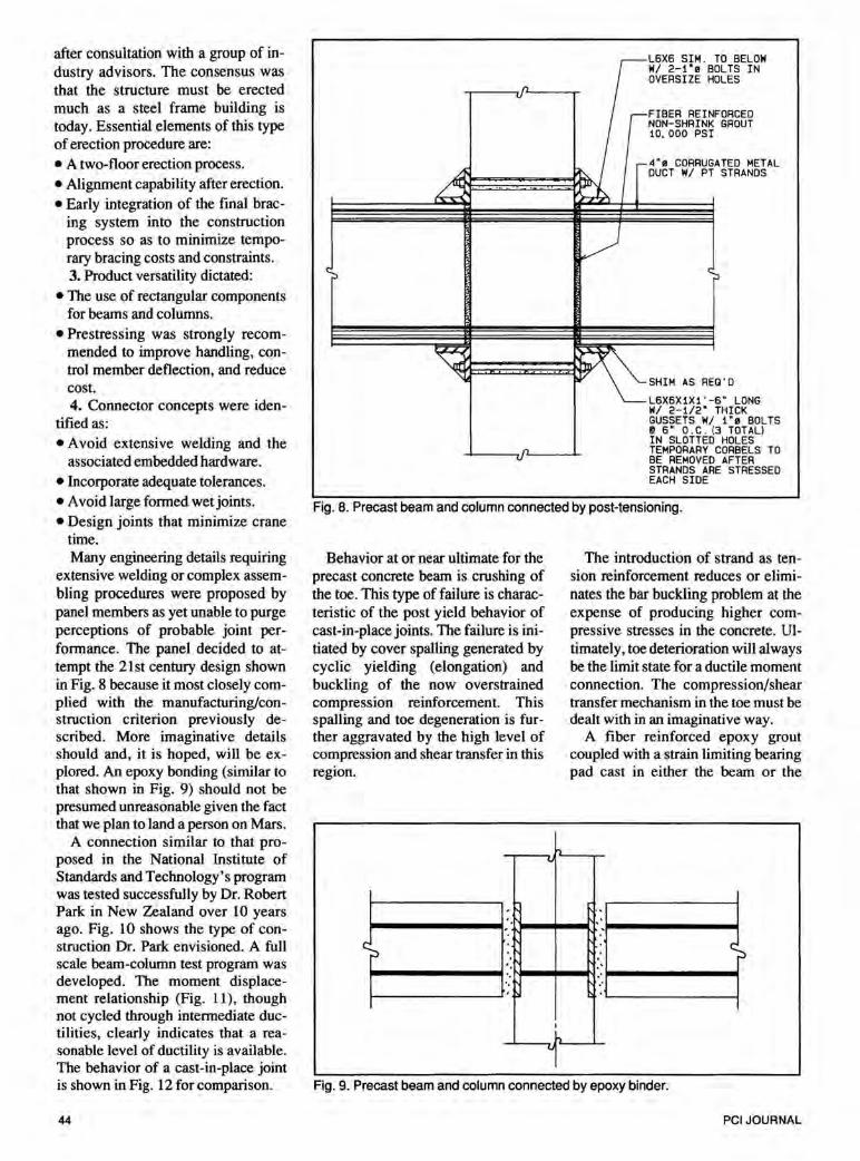
after consultation with a group of industry advisors. The consensus was that the structure must be erected much as a steel frame building is today. Essential elements of this type of erection procedure are: • A two-floor erection process. • Alignment capability after erection. • Early integration of the final brac
ing system into the construction process so as to minimize temporary bracing costs and constraints. 3. Product versatility dictated:
• The use of rectangular components for beams and columns.
• Prestressing was strongly recommended to improve handling, control member deflection, and reduce cost. 4. Connector concepts were iden
tified as: • A void extensive welding and the
associated embedded hardware. • Incorporate adequate tolerances. • A void large formed wet joints. • Design joints that minimize crane
time. Many engineering details requiring
extensive welding or complex assembling procedures were proposed by panel members as yet unable to purge perceptions of probable joint performance. The panel decided to attempt the 21st century design shown in Fig. 8 because it most closely complied with the manufacturing/construction criterion previously described. More imaginative details should and, it is hoped, will be explored. An epoxy bonding (similar to that shown in Fig. 9) should not be presumed unreasonable given the fact that we plan to land a person on Mars.
A connection similar to that proposed in the National Institute of Standards and Technology's program was tested successfully by Dr. Robert Park in New Zealand over 10 years ago. Fig. 10 shows the type of construction Dr. Park envisioned. A full scale beam-column test program was developed. The moment displacement relationship (Fig. 11), though not cycled through intermediate ductilities, clearly indicates that a reasonable level of ductility is available. The behavior of a cast-in-place joint is shown in Fig. 12 for comparison.
44
L6X6 SIM . TO BELOW W/ 2-1"e BOLTS IN OVERSIZE HOLES
FIBER REINFORCED NON-SHRINK GROUT 10, 000 PSI
4"e CORRUGATED METAL DUCT W/ PT STRANDS
SHIM AS REQ'D
L6X6X1X1'-6" LONG W/ 2-112" THICK GUSSETS W/ 1"e BOLTS @ 6" D.C. (3 TOTAL) IN SLOTTED HOLES TEMPORARY CORBELS TO BE REMOVED AFTER STRANDS ARE STRESSED EACH SIDE
Fig. 8. Precast beam and column connected by post-tensioning.
Behavior at or near ultimate for the precast concrete beam is crushing of the toe. This type of failure is characteristic of the post yield behavior of cast-in-place joints. The failure is initiated by cover spalling generated by cyclic yielding (elongation) and buckling of the now overstrained compression reinforcement. This spalling and toe degeneration is further aggravated by the high level of compression and shear transfer in this region.
v
The introduction of strand as tension reinforcement reduces or eliminates the bar buckling problem at the expense of producing higher compressive stresses in the concrete. Ultimately, toe deterioration will always be the limit state for a ductile moment connection. The compression/shear transfer mechanism in the toe must be dealt with in an imaginative way.
A fiber reinforced epoxy grout coupled with a strain limiting bearing pad cast in either the beam or the
~--------~-11-~--~-~--------~
Fig. 9. Precast beam and column connected by epoxy binder.
PC! JOURNAL
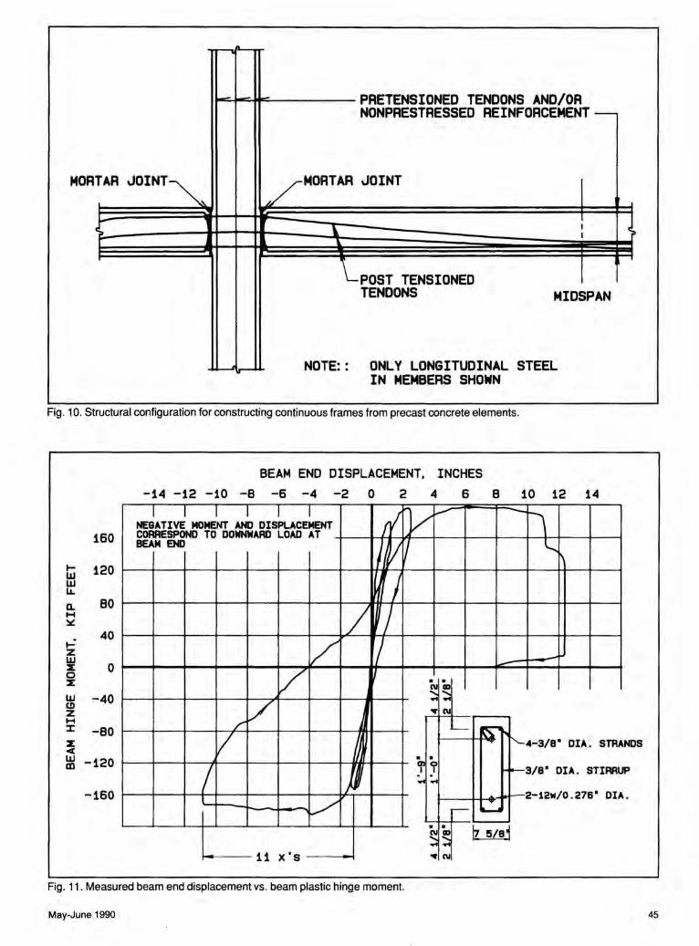
- .... - PRETENSIONED TENDONS AND/OR NONPRESTRESSED REINFORCEMENT---
MOR TAR JOINT~' /~MORTAR JOINT
~ I c \. I ~
~ ..
\_POST TENSIONED TENDONS MIDSPAN
NOTE:: ONLY LONGITUDINAL STEEL IN MEMBERS SHOWN
Fig. 10. Structural configuration for constructing continuous frames from precast concrete elements.
BEAM END DISPLACEMENT, INCHES -14 -12 -10 -8 -6 -4 -2 0 2 4 6 8 10 12 14
160
1- 120 UJ UJ LL.
a. 80 1-1 ~
....: 40 z w
0 2: 0 2:
w -40 (!) z .... :I: -eo 2: ~
I I I I I I ,; v ~ -~ NEGATIVE MOMENT AND DISPLACEMENT
CORRESPOND TO DOWNWARD LOAD AT BEAM END /jVI l.._
I / )
L v v v . .
~ I~
v .. .. .,-N
/ .___ ~ I ~4-3/8" DIA. STRA NOS
w -120 m
-160
.. 0!0
~3/8" DIA. STIRR ) I I .. ..
l ~2-12w/0 . 276" DIA v ....- ..........
UP
.. luL!j ~ I~ .. .. 11 x 's .,-N
Fig. 11. Measured beam end displacement vs. beam plastic hinge moment.
May-June 1990 45

U) Q. H ~
u.i u a: 0 I.J...
60
30
0
-30
-60 -1.0
td+l
-.5 0
STROKE, IN.
Fig. 12. Measured beam displacement vs. applied load.
column would better distribute the strain and thereby control concrete deterioration (Fig. 13). The development of imaginative cures must take precedence over determining the limit state of unimaginative load transfer concepts.
World Experience Precast concrete construction is not
only being used, but it is also being promoted in Japan on high rise buildings. The Japanese counterpart to the U.S. PRESSS program is charged with developing a national design standard for precast concrete construction by 1992. This lack of a national standard has not kept Japanese contractors from using precast concrete. Taisei Construction Company uses what they call "layered construction" to reduce construction time.
This system consists of precast columns, and a column joint shell developed so that it can receive a solid beam which in turn supports
46
form slabs. Seismic bracing is provided by a ductile frame. All beams contribute to the seismic bracing of the building. This bracing system is designed to emulate cast-inplace construction. Features that are significantly different from U.S. practice include the splicing of all column bars immediately above the floor with mechanical splices.
The technical justification for precast systems in Japan is provided by test. Japanese contractors test full scale subassemblies to a prescribed loading sequence in order to establish that the level of component ductility exceeds that which is required by the design criterion used. The ultimate design strength for precast systems is essentially the same as comparable cast-in-place systems.
The design criterion in Japan appears to accept a prescribed level of subassembly ductility as proof that sufficient building ductility exists. The equivalence of building "ductility and energy absorption" current-
5 x's
8/d -2.31
p •1.031
s •3.25"
d •13"
VELOCITY •0 . 1 IN. /SEC .
.5 1.0
ly required by U.S. codes must be reduced to a subassembly behavior criterion as it is in Japan. Comparative subassembly tests are the only logical way to determine whether the yield level prescribed for cast-inplace concrete is appropriate for precast concrete construction.
New Zealand codes, for example, require certain precast concrete bracing systems to be designed to a higher yield (1.25x) level than comparable cast-in-place systems. Clearly, there has been more focus abroad on the development of precast concrete building systems and design criteria than has occurred in the U.S.
The U.S. precast concrete industry must promote a performance type design philosophy if it is at all interested in the structural system market in regions where seismicity is a consideration. Boston, Massachusetts, and St. Louis, Missouri, are only two examples of places which now require seismic considerations. It is expected that many other areas of the
PCIJOURNAL
ELASTOMERIC BEARING PAD
_ ~FIBRE REINFORCED L_GROUT
BONDED P/T STRAND
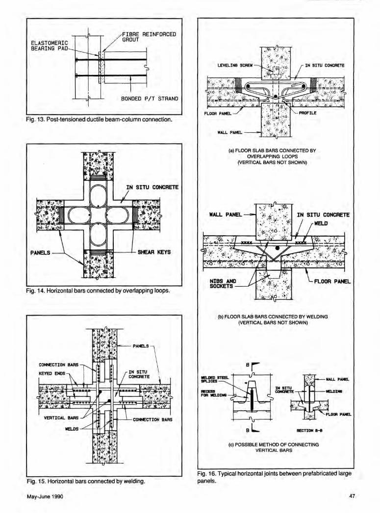
Fig. 13. Post-tensioned ductile beam-column connection.
IN SITU CONCRETE
Fig. 14. Horizontal bars connected by overlapping loops.
Fig. 15. Horizontal bars connected by welding.
May-June 1990
IN SITU CONCRETE
(a) FLOOR SLAB BARS CONNECTED BY OVERLAPPING LOOPS
(VERTICAL BAAS NOT SHOWN)
(b) FLOOR SLAB BAAS CONNECTED BY WELDING (VERTICAL BAAS NOT SHOWN)
aL !IECTIOII IHI
(c) POSSIBLE METHOD OF CONNECTING VERTICAL BAAS
Fig. 16. Typical horizontal joints between prefabricated large panels.
47
HiiH STRENGTH GROUT
FOAM PLASTIC COLLAR DRY PACK MORT
(a)
OUTLET TUBE
INLET TUBE
PLASTIC BEARING STRIP
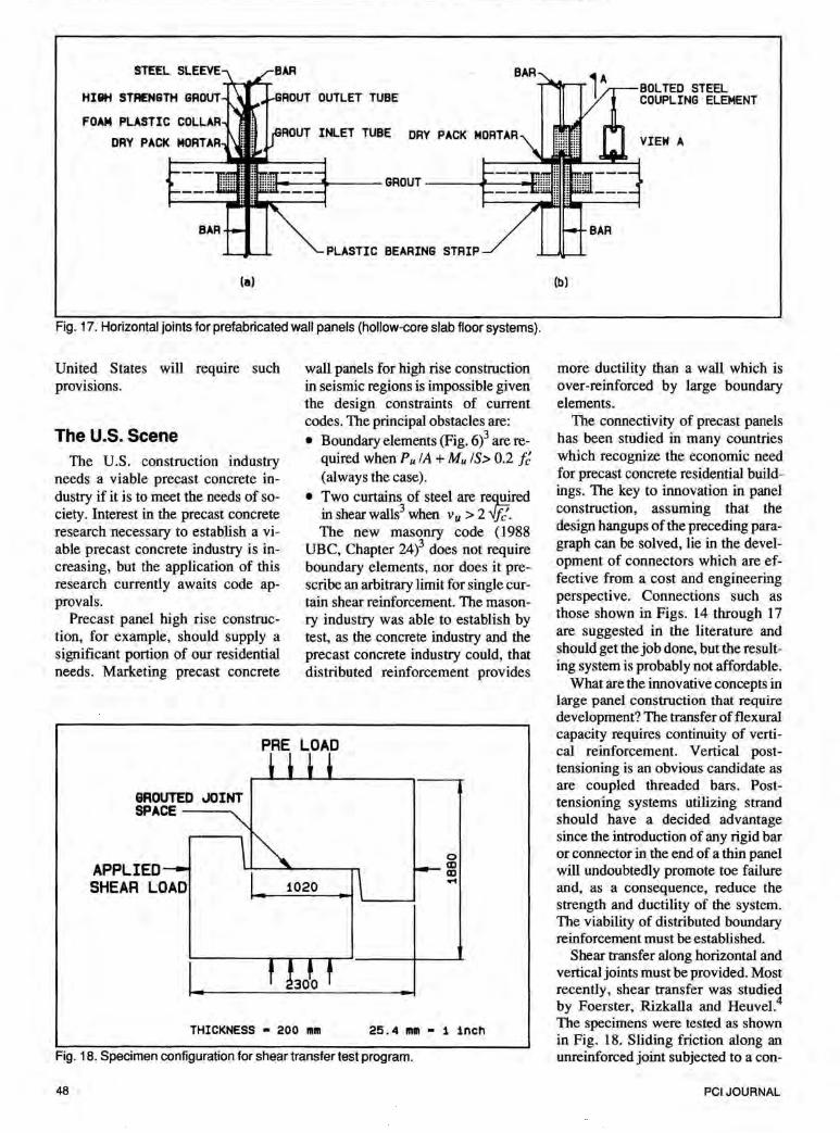
Fig. 17. Horizontal joints for prefabricated wall panels (hollow-core slab floor systems).
United States will require such provisions.
The U.S. Scene The U.S. construction industry
needs a viable precast concrete industry if it is to meet the needs of society. Interest in the precast concrete research necessary to establish a viable precast concrete industry is increasing, but the application of this research currently awaits code approvals.
Precast panel high rise construction, for example, should supply a significant portion of our residential needs. Marketing precast concrete
wall panels for high rise construction in seismic regions is impossible given the design constraints of current codes. The principal obstacles are: • Boundary elements (Fig. 6)3 are re
quired when PulA+ Mu IS> 0.2 f~ (always the case).
• Two curtains of steel are re~red in shear walls3 when Vu > 2 --Jj(. The new masonry code ( 1988
UBC, Chapter 24)3 does not require boundary elements, nor does it prescribe an arbitrary limit for single curtain shear reinforcement. The masonry industry was able to establish by test, as the concrete industry and the precast concrete industry could, that distributed reinforcement provides
PRE LOAD
&ROUTED JOINT SPACE---...
APPLIED SHEAR LOAD
THICKNESS • 200 mm
0 CD ([) ....
25.4 mm • 1 inch
Fig. 18. Specimen configuration for shear transfer test program.
48
(b)
BOLTED STEEL COUPLING ELEMENT
more ductility than a wall which is over-reinforced by large boundary elements.
The connectivity of precast panels has been studied in many countries which recognize the economic need for precast concrete residential buildings. The key to innovation in panel construction, assuming that the design hangups of the preceding paragraph can be solved, lie in the development of connectors which are effective from a cost and engineering perspective. Connections such as those shown in Figs. 14 through 17 are suggested in the literature and should get the job done, but the resulting system is probably not affordable.
What are the innovative concepts in large panel construction that require development? The transfer of flexural capacity requires continuity of vertical reinforcement. Vertical posttensioning is an obvious candidate as are coupled threaded bars. Posttensioning systems utilizing strand should have a decided advantage since the introduction of any rigid bar or connector in the end of a thin panel will undoubtedly promote toe failure and, as a consequence, reduce the strength and ductility of the system. The viability of distributed boundary reinforcement must be established.
Shear transfer along horizontal and vertical joints must be provided. Most recently, shear transfer was studied by Foerster, Rizkalla and Heuvel.4
The specimens were tested as shown in Fig. 18. Sliding friction along an unreinforced joint subjected to a con-
PCI JOURNAL
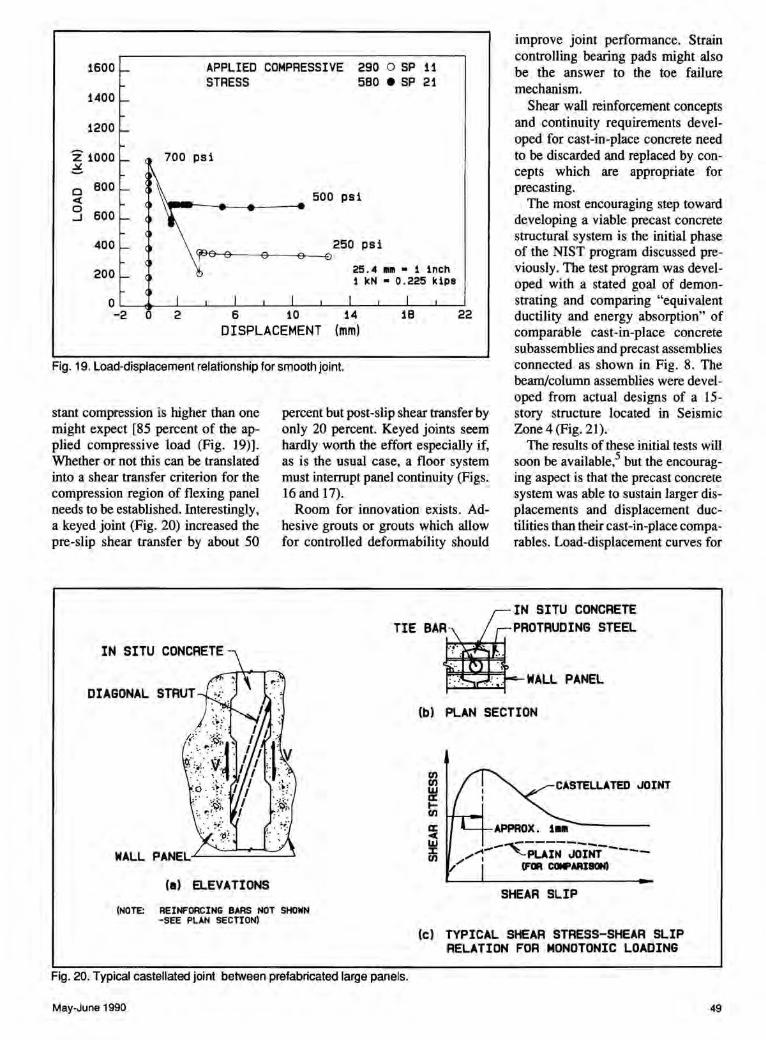
1600 APPLIED COMPRESSIVE 290 0 SP 11 STRESS 580 e SP 21
1400
1200
z 1000 ~
0 800 < 0 600 ...J
400
200
0
700 psi
500 psi
25.4 1111 • 1 inch 1 kN • 0 . 225 kips
-2 2 6 10 14 22 DISPLACEMENT (mm)
Fig. 19. Load-displacement relationship for smooth joint.
stant compression is higher than one might expect [85 percent of the applied compressive load (Fig. 19)]. Whether or not this can be translated into a shear transfer criterion for the compression region of flexing panel needs to be established. Interestingly, a keyed joint (Fig. 20) increased the pre-slip shear transfer by about 50
DIAGONAL STRUT
percent but post-slip shear transfer by only 20 percent. Keyed joints seem hardly worth the effort especially if, as is the usual case, a floor system must interrupt panel continuity (Figs. 16 and 17).
Room for innovation exists. Adhesive grouts or grouts which allow for controlled deformability should
improve joint performance. Strain controlling bearing pads might also be the answer to the toe failure mechanism.
Shear wall reinforcement concepts and continuity requirements developed for cast-in-place concrete need to be discarded and replaced by concepts which are appropriate for precasting.
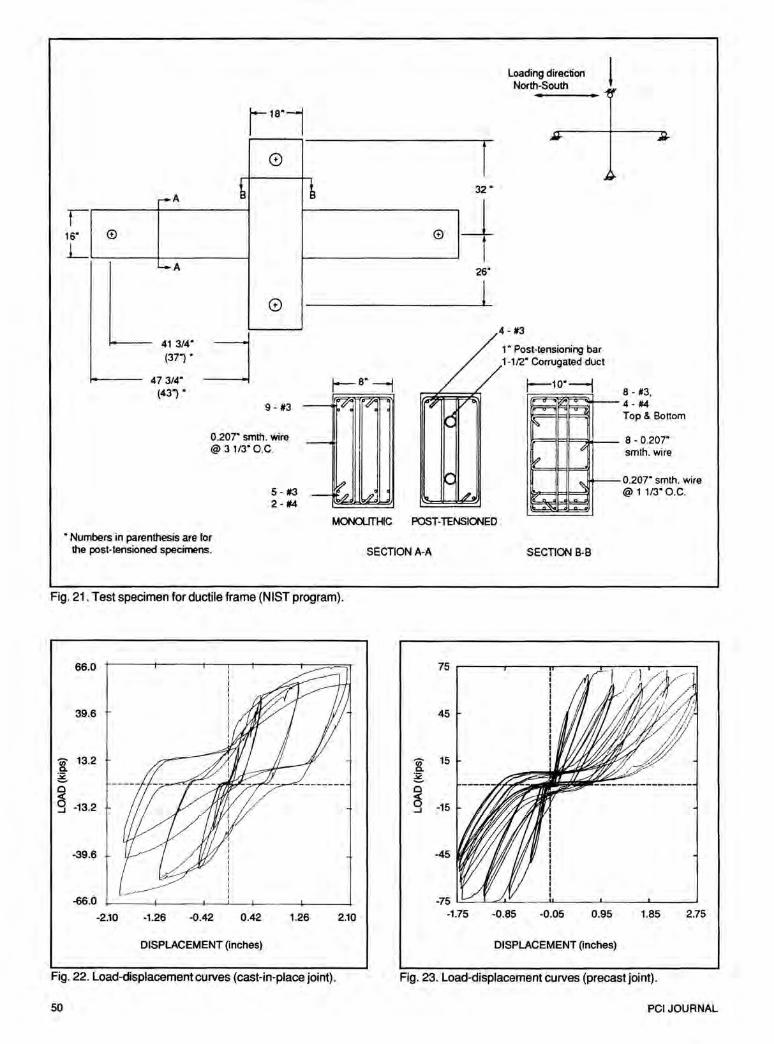
The most encouraging step toward developing a viable precast concrete structural system is the initial phase of the NIST program discussed previously. The test program was developed with a stated goal of demonstrating and comparing "equivalent ductility and energy absorption" of comparable cast-in-place concrete subassemblies and precast assemblies connected as shown in Fig. 8. The beam/column assemblies were developed from actual designs of a 15-story structure located in Seismic Zone 4 (Fig. 21).
The results of these initial tests will soon be available,5 but the encouraging aspect is that the precast concrete system was able to sustain larger displacements and displacement ductilities than their cast-in-place comparables. Load-displacement curves for
IN SITU CONCRETE PROTRUDING STEEL
WALL PANEL
(b) PLAN SECTION
(a) ELEVATIONS
(NOTE: REINFORCING BARS NOT SHOWN -SEE PLAN SECTION)
Fig. 20. Typical castellated joint between prefabricated large panels.
May-June 1990
en en ~ len
~ UJ :I: en
CASTELLATED JOINT
SHEAR SLIP
(c) TYPICAL SHEAR STRESS-SHEAR SLIP RELATION FOR MONOTONIC LOADING
49
r-A
16" ® L
-A
41 3/4" (37") •
47 3/4" (43").
8
L ~
®
8
_j . 9-13 -V'"i w
r 32.
j_ t
26"
l
Loading direction l North-South
1" Post-tensioning bar 1-112" Corrugated duct
8- #3, [0 ·--4-#4
Top & Bottom
0.207" smih. wire 8 - 0.207" ~
@ 3 1/3" O.C. smth. wire
~-0.207" smth. wire
- ,.,?, 5- 13 @ 1 1/3" O.C. 2- #4
MONOUTHIC POST-TENSIONED
• Numbers in parenthesis are for the post-tensioned specimens.
Fig. 21. Test specimen for ductile frame (NIST program).
66.0
39.6
'[ 13.2 ;g, 0 c(
g -13.2
-39.6
-66.0
-2.10 -1.26 -0.42 0.42 1.26
DISPLACEMENT (inches)
Fig. 22. Load-displacement curves (cast-in-place joint).
50
2.10
SECTION A-A SECTION B-B
45
Cii' 15 a. ;g. 0
~ -15 ...J
-45
-75 '-=.._......jl......<:..L.:.... __ ....u.... __ __. ___ ..__ __ __.
-1.75 -0.85 -0.05 0.95 1.85 2.75
DISPLACEMENT (inches)
Fig. 23. Load-displacement curves (precast joint).
PCIJOURNAL
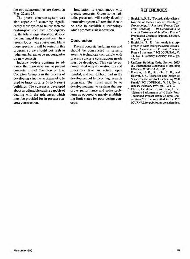
the two subassemblies are shown in Figs. 22 and 23.
The precast concrete system was also capable of sustaining significantly more cycles to failure than the cast-in-place specimen. Consequently, the total energy absorbed, despite the pinching of the precast beam hysteresis loops, was equivalent. Many more specimens will be tested in this program so we should not rush to judgment, but rather be encouraged to try new concepts.
Industry leaders continue to advance the innovative use of precast concrete. Lloyd Compton of L.A. Compton Group is in the process of developing a ductile fascia panel to be used to brace midrise (4 to 6 story) buildings. The concept is developed about an adjustable casting capable of dealing with the tolerances which must be provided for in precast concrete construction.
May-June 1990
Innovation is synonymous with precast concrete. Given some latitude, precasters will surely develop innovative systems. It remains then to be able to establish a technology which promotes this innovation.
Conclusion Precast concrete buildings can and
should be constructed in seismic areas. A technology compatible with precast concrete construction needs must be developed. This can be accomplished only if constructors and precasters take an active, open minded, and yet stubborn part in the development of forthcoming research programs. The thrust must be to develop imaginative systems that improve performance and solve problems as opposed to merely establishing limit states for poor design concepts.
REFERENCES
1. Englekirk, R. E., "Towards a More Effective Use of Precast Concrete Cladding," Proceedings, Architectural Precast Concrete Cladding - Its Contribution to Lateral Resistance of Buildings, Precast/ Prestressed Concrete Institute, Chicago, IL, 1990,pp. 4-13.
2. Englekirk, R. E., "An Analytical Approach to Establishing the Seismic Resistance Available in Precast Concrete Frame Structures," PCI JOURNAL, V. 34, No. l, January-February 1989, pp. 92-101.
3. Uniform Building Code, Section 2625 (f), International Conference of Building Officials, Whittier, CA, 1985.
4. Foerster, H. R., Rizkalla, S. H., and Heuvel, J. S., "Behavior and Design of Shear Connections for Loadbearing Wall Panels" PCI JOURNAL, V. 34, No. 1, January-February 1989, pp. 102-119.
5. Cheok, Geraldine S., and Lew, H. S., "Seismic Performance of 1;3 Scale PostTensioned Precast Beam-Column Connections;· : to be submitted to the PCI JOURNAL for publication consideration.
51