seismic behaviour of rc building resting … behaviour of rc building resting on plain and sloping...
TRANSCRIPT

International Research Journal of Engineering and Technology (IRJET) e-ISSN: 2395 -0056
p-ISSN: 2395-0072 Volume: 04 Issue: 06 | June -2017 www.irjet.net
© 2017, IRJET | Impact Factor value: 5.181 | ISO 9001:2008 Certified Journal | Page 1793
SEISMIC BEHAVIOUR OF RC BUILDING RESTING ON PLAIN AND
SLOPING GROUND WITH BRACINGS AND SHEAR WALL
Yashaswini R1, Dr. Mahesh Kumar G2
1M.Tech Student, CAD Structures, Shridevi Institute of Engineering and Technology, Karnataka, India 2Professor, Dept. of Civil Engineering, Shridevi Institute of Engineering and Technology, Karnataka, India
---------------------------------------------------------------------------***------------------------------------------------------------------------
Abstract - Due to the sloping ground the column height differs as short and long column. Hence the large amount of lateral force is attracted by short column due to its higher stiffness. It leads to severe damage to structure and causes loss of human life. The introduction of lateral force resisting systems such as shear wall, bracings performs better during earthquake. In this present study, 10 storey RC building resting on plain and sloping ground of different slope angles 10°, 20°, 30° with the horizontal situated in seismic zone 5 and on medium type soil is considered. The analysis is carried out by using ETABS V9.7 software, to study the effect of shear wall and bracings on plain and sloping ground. The results are analysed for seismic parameters such as base shear, Storey displacement, Storey drift and Fundamental time period. By this analysis, the configuration of building structure suitable for resisting lateral loads on plain and sloping ground is suggested.
Key words : Building on sloping ground, building on plain ground, bracings, shear wall, response spectrum analysis.
1. INTRODUCTION: In hilly areas the availability of flat or levelled ground is very less, the terrain condi tion has almost sloping ground. So that centre of rigidity and centre of mass on various floors does not coincides. Also the building on sloping ground is torsionally coupled and in both vertical and horizontal planes, they are unsymmetrical and irregular. Due to this the structural capacity of building will decreases. For the economic development of hilly areas, urbanization plays a very important role, so that there has been a great demand for the improvement of these areas by multi-storey building construction.
1.1 Shear wall : Shear wall is a vertical reinforced concrete member or an element provided to ensure resistance against lateral loads and as well as vertical loads. It has greater strength and stiffness and high lateral load resistance capacity. Usually shear wall is considered for complete height of building with columns and beams from the level of foundation. Its thickness varying from 150 to 400 mm. Up to 30 storeys shear wall is economical.
1.2 Braced frames: These are the members, used to resist compression and tension forces, which are provided in wall panels. It prevents the sway of structure by transferring the lateral forces sideways down to the ground by holding the structure stable. For effectively carrying of tension and compression forces bracings can be arranged in many forms, cross bracings is one of the common arrangement.
1.3 Objectives:
To model the 10 storey building resting on plain ground and sloping ground having slope of 10°, 20°, 30° with the horizontal situated in zone 5 and on medium soil type, for bare frame, with X bracings and shear wall using ETABS software.
To analyse the building with various lateral load analysis method. To perform analysis and to compare results of seismic parameters.
2. BUILDING DESCRIPTION: Model consists of 10 storey RC building having 4 bays in both directions, each bay width is 5m, storey height 3.2 m. The RC frame consists of beam and column size is 0.45 x 0.45 m. slab thickness 120 mm, shear wall thickness 150 mm, grade of concrete M30 for beam, slab, shear wall, M40 for column, grade of steel Fe 500.

International Research Journal of Engineering and Technology (IRJET) e-ISSN: 2395 -0056
p-ISSN: 2395-0072 Volume: 04 Issue: 06 | June -2017 www.irjet.net
© 2017, IRJET | Impact Factor value: 5.181 | ISO 9001:2008 Certified Journal | Page 1793
3. LOADS CONSIDERED
Live load = 3 kN/m2
Floor finishes = 1.5 kN/m2
Wall load on floor and roof = 12.65 kN/m2 and 3 kN/m2 respectively.
4. METHOD OF ANALYSIS AND MODELLING OF BUILDING
Response spectrum method is used for analysis of the given building. As per from IS 1893 part 1 2002 by multiplying base shear ratio Vb/VB the results of dynamic responses can be obtained. Where Vb base shear can be obtained from equation, VB obtained from dynamic analysis. In both x and y directions dynamic responses of structure can be found. The ratio of Vb/VB should be greater than one. Zone V, Zone factor is 0.36 Importance factor is 1, Response reduction factor is 5, Medium Soil condition, damping ratio is 5%.
Table 1: Calculation of length of column according to slope angle
Slope angle Length of column from plinth (m)
10° 0.88 1.76 2.64 3.52 4.4 20° 1.81 3.62 5.43 7.24 9.05 30° 2.88 5.76 8.64 11.52 14.4
4.1 Models considered
Model 1 : Bare frame on plain ground Model
2 : With X bracings on plain ground Model 3
: With Shear wall on plain ground Model 4 :
Bare frame on 10° sloping ground
Model 5 : With X bracings on 10° sloping ground
Model 6 : With Shear wall on 10° sloping ground
Model 7 : Bare frame on 20° sloping ground
Model 8: With X bracings on 20° sloping ground
Model 9 : With Shear wall on 20° sloping ground
Model 10 : Bare frame on 30° sloping ground
Model 11 : With X bracings on 30° sloping ground
Model 12 : With Shear wall on 30° sloping ground
International Research Journal of Engineering and Technology (IRJET) e-ISSN: 2395 -0056
p-ISSN: 2395-0072 Volume: 04 Issue: 06 | June -2017 www.irjet.net
© 2017, IRJET | Impact Factor value: 5.181 | ISO 9001:2008 Certified Journal | Page 1793
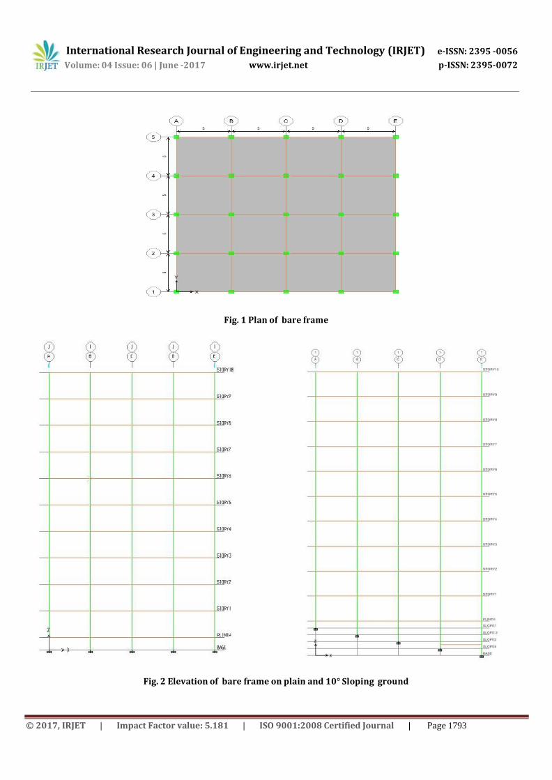
Fig. 1 Plan of bare frame
Fig. 2 Elevation of bare frame on plain and 10° Sloping ground

International Research Journal of Engineering and Technology (IRJET) e-ISSN: 2395 -0056
p-ISSN: 2395-0072 Volume: 04 Issue: 06 | June -2017 www.irjet.net
© 2017, IRJET | Impact Factor value: 5.181 | ISO 9001:2008 Certified Journal | Page 1793
Ba
se S
he
ar
(kN
)
Fig. 3 Elevation of bare frame on 20° and 30° Sloping ground
5. RESULTS AND DISCUSSION
5.1 Base Shear
3600
3200
2800
2400
2000
1600
1200
800
400
0
Base shear in X direction (kN)
Bare frame
With X bracings
With Shear wall
Plain ground
10° Sloping ground
20° Sloping ground
30° Sloping ground

International Research Journal of Engineering and Technology (IRJET) e-ISSN: 2395 -0056
p-ISSN: 2395-0072 Volume: 04 Issue: 06 | June -2017 www.irjet.net
© 2017, IRJET | Impact Factor value: 5.181 | ISO 9001:2008 Certified Journal | Page 1793
Sto
rey
dis
pla
cem
en
t (m
m)
Sto
rey
dis
pla
cem
en
t (m
m)
Ba
se S
he
ar
(kN
)
3600
3200
2800
2400
2000
1600
1200
800
400
0
Plain
10° Sloping 20° Sloping 30° Sloping
Bare frame
With X bracings
With Shear wall
ground
ground
ground
ground
Fig. 4 Variation of base shear in X and Y direction on plain and sloping ground
5.2 Storey displacement
Maximum Storey displacement in X direction (mm)
45
40
35
30
25 Bare frame 20
With X bracings 15 10 With Shear wall
5 0
Plain ground 10° Sloping ground
20° Sloping ground
30° Sloping ground
Maximum Storey displacement in Y direction (mm)
45 40 35 30
25 20 15 10
5 0
Bare frame
With Shear wall
Plain ground 10° Sloping ground
20° Sloping ground
30° Sloping ground
Base shear in Y direction (kN)
With X bracings

International Research Journal of Engineering and Technology (IRJET) e-ISSN: 2395 -0056
p-ISSN: 2395-0072 Volume: 04 Issue: 06 | June -2017 www.irjet.net
© 2017, IRJET | Impact Factor value: 5.181 | ISO 9001:2008 Certified Journal | Page 1793
No
. of
Sto
rey
s F
un
da
me
nta
l tim
e p
eri
od
(se
c)
Fig. 5 Variation of maximum storey displacement in X and Y direction on plain and sloping ground
5.3 Fundamental time period
2
1.8
1.6
1.4
1.2
1
0.8
0.6
0.4
0.2 0
Maximum Fundamental time period (sec)
Bare frame
With X bracings
With Shear wall
Plain ground 10° Sloping ground
20° Sloping ground
30° Sloping ground
Fig. 6 Variation of maximum fundamental time period on plain and sloping ground
5.4 Storey drift
Storey drift in X direction for plain ground (mm)
10
9
8
7
6
5
4
3
2
1
0 0.0003 0.0006 0.0009 0.0012 0.0015 0.0018
Storey drift (mm)
Bare frame
With X bracings
With Shear wall

International Research Journal of Engineering and Technology (IRJET) e-ISSN: 2395 -0056
p-ISSN: 2395-0072 Volume: 04 Issue: 06 | June -2017 www.irjet.net
© 2017, IRJET | Impact Factor value: 5.181 | ISO 9001:2008 Certified Journal | Page 1793
No
. of
Sto
rey
s
Storey drift in Y direction for plain ground (mm)
10
9
8
7
6
5
4
3
2
1
0 0.0003 0.0006 0.0009 0.0012 0.0015 0.0018
Storey drift (mm)
Bare frame
With X bracings
With Shear wall
Fig. 7 Variation of Storey drift in X and Y direction on plain ground
6. CONCLUSIONS
1. The introduction of Shear wall and X bracings to the structure increases base shear and decreases fundamental time
period, storey drift and storey displacement for plain ground and sloping ground.
2. For the better performance of a structure on plain and sloping ground shear wall will gives better performa nce for
resisting lateral force during earthquake compared to other configurations.
REFERENCES
1. Raghavendra et al. (2016) “Seismic Evaluation with Shear walls and Braces for Buildings on Sloping Ground.” International Journal of Innovative Research in Science, Engineering and Technology (IJIRSET). Volume 5, Issue 6.
2. D. J. Misal1 and M. A. Bagade2 (2016) “Study of Seismic Behaviour of Multi Storied RCC buildings Resting on Sloping Ground and Considering Bracing System.” International Journal of Engineering Research. Volume 5, Issue 3.
3. S.P. Pawar et al. (2016) “Effect of Positioning of RC Shear walls of Different Shapes on Seismic Performance of Buildings Resting on Sloping Ground.” International Journal of Civil Engineering and Technology (IJC IET). Volume 7, Issue 3.
4. Manjunath C S1 and Siddu Karthik C S2 (2016) “Seismic Performance of RC Buildings on Sloping Grounds with Different Types of Bracings.” International Journal of Research in Engineering and Technology (IJRET). Volume 5, Issue 2.
5. Reshma H K1 and Dr. B Shivakumara Swamy2 (2016) “Seismic Evaluation of RC Frame Building with Bracings Resting on Varying ground Profile.” International Research Journal of Engineering and Technology (IRJET). Volume 3, Issue 11.
CODES:
1. IS 1893 (Part1) 2002 Criteria for Earthquake Resistant Design of Structures.