seismic analysis and design of a multi-storey building located in haql...
TRANSCRIPT
Journal of Soft Computing in Civil Engineering 1-2 (2017) 35-51
journal homepage: http://www.jsoftcivil.com/
Seismic Analysis and Design of a Multi-Storey
Building Located in Haql City, KSA
M. Ismaeil1*
, Kh. Elhadi2, Y. Alashker
2 and I. Eldin Yousef
3
1. Assistant Professor, Department of Civil Engineering, King Khalid University, KSA. On leave from Sudan
University for Science and Technology, Khartoum, Sudan.
2. Assistant Professor, Department of Civil Engineering, King Khalid University, KSA. On leave from Structural
Engineering Department, Zagazig University, Zagazige, Egypt.
3. Lecturer, Department of Civil Engineering, King Khalid University, KSA.
Corresponding author: [email protected]
ARTICLE INFO
ABSTRACT
Article history:
Received: 29 July 2017
Accepted: 02 August 2017
Recently the design of RC building to mitigate seismic loads
has received a great attention. Since Saudi Arabia has low to
moderate seismicity, most of buildings were designed only
for gravity load. The objective of this paper is to analysis
design RC building located in the most active seismic zone
region in Saudi Arabia to mitigate seismic loads. A multi-
storey reinforced concrete building, in Haql city, was
seismically analyzed and designed using the Equivalent
Lateral Force Procedure with the aid of SAP200 software.
The chosen buildings which was Ordinary Moment Resisting
Frame (OMR), was analyzed and designed by using SBC
301 (2007) Saudi Building Code [1], SAP2000 (structural
analysis software) [2] and ISACOL "Information Systems
Application on Reinforced Concrete Columns" [3]. The
results showed that the current design of RC buildings
located in the most active seismic zone region in Saudi
Arabia, Haql city was found unsafe, inadequate and
unsatisfied to mitigate seismic loads.
Keywords:
SAP2000,
SBC 301 (2007),
Active Seismic Zone Region,
Saudi Arabia,
Equivalent Static Method,
Seismic Loads.
1. Introduction
Haql is a town in the northwest of Saudi Arabia near the head of the Gulf of Aqaba, adjacent to
Aqaba across the Jordanian border. The coasts of Egypt, Israel and Jordan can be seen from
Haql. Haql city is located in the most active seismic zone region of the Kingdom of Saudi Arabia
where there is a complicated geological structures and tectonics. This paper is an attempt to
study the effect of seismic loads on RC residential buildings located in the most active seismic
zone region of the Kingdom of Saudi Arabia. Saudi Arabia is not free from earthquakes. It has
36 M. Ismaeil et al./ Journal of Soft Computing in Civil Engineering 1-2 (2017) 35-51
experienced many earthquakes during the recent history, and the previous studies in this field
demonstrated this argument. Most of existing buildings in Saudi Arabia do not meet the current
design standards due to design shortage or construction shortcomings.
The last major event was the 1995 Haql earthquake in the Gulf of Aqaba (magnitude 7.3) which
caused significant damage on both sides of the Gulf and was felt hundreds of kilometres away.
As far as Saudi Arabia is concerned, the most active area is along the Gulf of Aqaba (Dead Sea
transform fault). On 19 May, 2009, 19 earthquakes of M4.0 or greater took place in the volcanic
area of Harrat Lunayyir to the north of Yanbu, including a M5.4 event that caused minor damage
to structures [4]. The 1995 Gulf of Aqaba earthquake (also known as Nuweiba earthquake)
occurred in November 22 at 06:15 local time (04:15 UTC) and registered 7.3 on the moment
magnitude scale. The epicentre was located in the central segment of the Gulf of Aqaba. The
earthquake occurred along the Dead Sea Transform (DST) fault system, an active tectonic plate
boundary with seismicity that is characterized by long-running quiescent periods with occasional
large and damaging earthquakes, along with intermittent earthquake swarms. It was the strongest
tectonic event in the area for many decades and caused injuries, damage, and deaths throughout
the Levant and is also thought to have remotely triggered a series of small to moderate
earthquakes 500 kilometres (310 miles) to the north of the epicentre. In the aftermath of the
quake, several field investigations set out to determine the extent of any surface faulting, and the
distribution of aftershocks was analyzed. Areas affected: Egypt, Israel, Jordan and Saudi Arabia
as shown in Figure 1[4]. Recent studies, historical evidences, geological and geophysical
observations indicate that parts of the Kingdom fall within seismic risk regions. In western Saudi
Arabia, a design peak ground acceleration (PGA) ranging from 0.03g to 0.26g for an economic
life of 50 years was suggested. Seismic zonation was established with zone numbers 0, 1, 2A,
and 2B [5]. Saudi Arabia is not free from earthquakes. It has experienced many earthquakes
during the recent history, and the previous studies in this field demonstrated this argument. Most
of existing buildings in Saudi Arabia do not meet the current design standards due to design
shortage or construction shortcomings. Therefore, buildings should be designed regarding their
capacity for resisting expected seismic effects. The seismic hazard analysis for the Kingdom was
performed [6, 7]. Seismograph stations of the Saudi National Seismic Network as shown in
Figure 2 [8], was developed for the Kingdom based on the peak ground acceleration, PGA,
values calculated for 50 years service lifetime with 10% probability of being exceeded.

M. Ismaeil et al./ Journal of Soft Computing in Civil Engineering 1-2 (2017) 1-2 (2017) 35-51 37
Figure 1: 1995 Gulf of Aqaba earthquake [4]
Figure 2: Seismograph stations of the Saudi National Seismic Network [8]
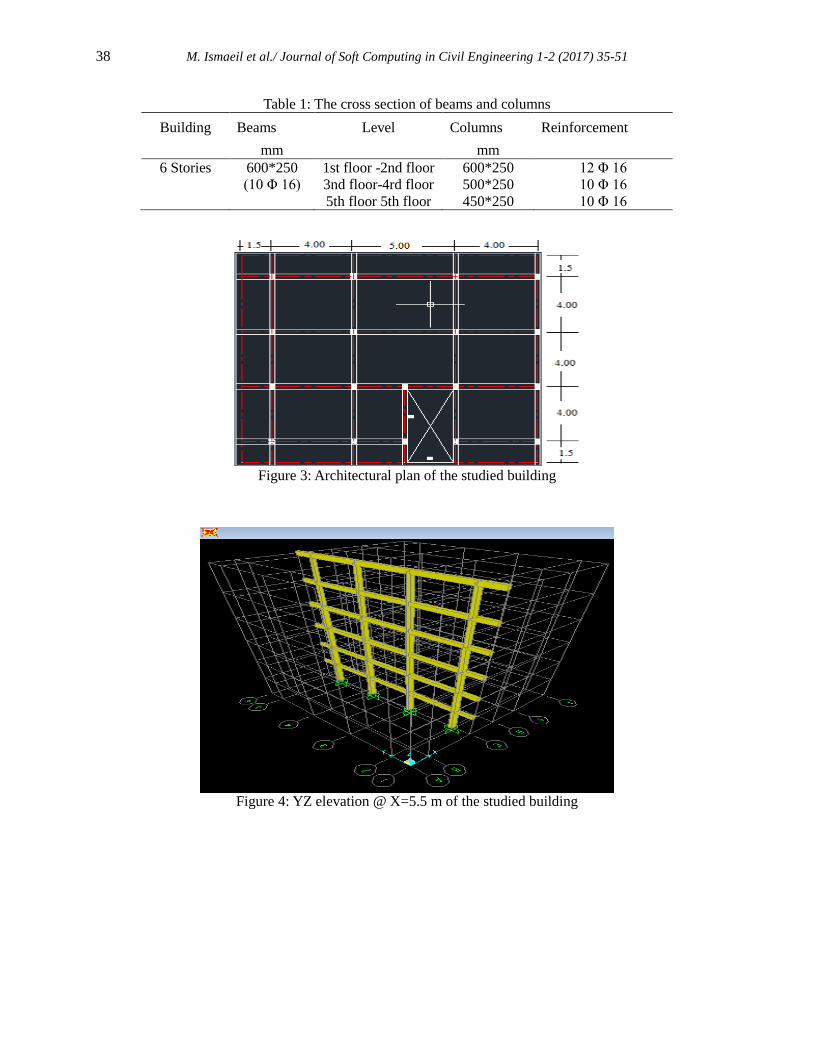
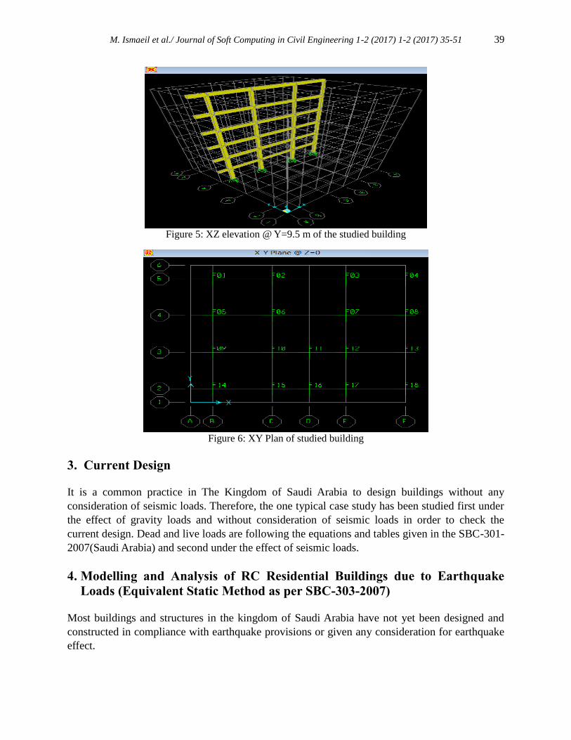
2. Description and Model of the Building
A six-storey residential buildings with plan and elevations as shown in Figures 3 to 6 is
considered for study. The building is composed of moment resisting RC frame with solid slab,
140mm thickness, situated in the most active seismic zone region of the Kingdom of Saudi
Arabia. The structure members are made of in-situ reinforced concrete .The overall plan of
building is square with dimensions 14.5x15m as shown in Figure 3. Height of the building is 16
m and storey height for each floor is 3.2 m. Columns and beams sizes are shown in Table 1. The
building is approximately symmetric in both directions. The plan and some frames of the studied
building as shown in Figures 3 to 5. Beams and columns have been modelled as frame elements
while in-plane rigidity of the slab is simulated using rigid diaphragm action. The columns are
assumed to be fixed at the base. The building is analyzed.
as per seismic provisions provided by SBC 301-2007.
38 M. Ismaeil et al./ Journal of Soft Computing in Civil Engineering 1-2 (2017) 35-51
Table 1: The cross section of beams and columns
Building Beams Level Columns Reinforcement
mm
mm
6 Stories 600*250 1st floor -2nd floor 600*250 12 Φ 16
(10 Φ 16) 3nd floor-4rd floor 500*250 10 Φ 16
5th floor 5th floor 450*250 10 Φ 16
Figure 3: Architectural plan of the studied building
Figure 4: YZ elevation @ X=5.5 m of the studied building
M. Ismaeil et al./ Journal of Soft Computing in Civil Engineering 1-2 (2017) 1-2 (2017) 35-51 39
Figure 5: XZ elevation @ Y=9.5 m of the studied building
Figure 6: XY Plan of studied building
3. Current Design
It is a common practice in The Kingdom of Saudi Arabia to design buildings without any
consideration of seismic loads. Therefore, the one typical case study has been studied first under
the effect of gravity loads and without consideration of seismic loads in order to check the
current design. Dead and live loads are following the equations and tables given in the SBC-301-
2007(Saudi Arabia) and second under the effect of seismic loads.
4. Modelling and Analysis of RC Residential Buildings due to Earthquake
Loads (Equivalent Static Method as per SBC-303-2007)
Most buildings and structures in the kingdom of Saudi Arabia have not yet been designed and
constructed in compliance with earthquake provisions or given any consideration for earthquake
effect.
40 M. Ismaeil et al./ Journal of Soft Computing in Civil Engineering 1-2 (2017) 35-51
The horizontal seismic loads are defined according to Saudi Buildings Code (SBC-303-2007).
The lateral force effect on the structure can be translated to equivalent lateral force at the base of
the structure which can be distributed to different stories. According to Saudi Buildings Code
(SBC-303-2007), the total seismic base shear force V is determined as follows:
V = Cs*W )1(
Where: Cs is the seismic coefficient, W is the total weight and V is the base shear. The seismic
design coefficient (Cs) shall be determined in accordance with the following equation:
Cs = SDS / (R / I) )2(
Where, SDS = Design spectral response acceleration in the short period range
R = Response modification factor
I = Occupancy importance factor determined
The value of the seismic response coefficient, (Cs), need not be greater than the following
equation:
Cs = SD1 / [T. (R / I)] )3(
But shall not be taken less than.
T = 0.1N )4(
Where N = Number of stories
Cs = 0.044SDS I )5(
Where, SDS = Design spectral response acceleration at a period of 1 sec
T = Fundamental period of the structure (sec)
Design earthquake spectral response acceleration at short periods, SDS, and at 1-sec period,
SD1, shall be as follows.
SMS= Fa*SS )6(
SM1= Fv*S1 )7(
SDS= 2/3*SMS )8(
SD1= 2/3*SM1 )9(
Where:
SS: the maximum spectral response acceleration at short periods
S1: the maximum spectral response acceleration at a period of 1 sec
Fa: acceleration-based site coefficient
M. Ismaeil et al./ Journal of Soft Computing in Civil Engineering 1-2 (2017) 1-2 (2017) 35-51 41
Fv: velocity-based site coefficient
SMS: the maximum spectral response acceleration at short periods adjusted for site class
SM1: the maximum spectral response acceleration at a period of 1 sec adjusted for site class
SDS: the design spectral response acceleration at short periods
SD1: the design spectral response acceleration at a period of 1 sec
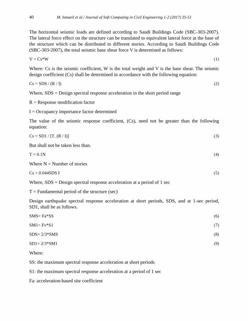
5. Vertical Distribution of Base Force
The buildings are subjected to a lateral load distributed across the height of the buildings
based on the following formula specified by Saudi Buildings Code (SBC-303-2007):
Where, Fx is the applied lateral force at level ‘x’, W is the storey weight, h is the storey height
and V is the design base shear, and N is the number of stories. The summation in the denominator
is carried through all storey levels. This results in an inverted triangular distribution when k is set
equal to unity. A uniform lateral load distribution consisting of forces that are proportional to the
storey masses at each storey level.
k = an exponent related to the structure period as follows:
For structures having a period of 0.5 sec or less, k = 1
For structures having a period of 2.5 sec or more, k= 2
6. LOAD COMBINATIONS AS PER SBC-303-2007
As per SBC-301 section 2.3, following load combinations should be considered for design of
structures, components, and foundations.
1.4 (D + F)
1.2 (D + F + T) + 1.6 (L + H) + 0.5 (Lr or R)
1.2 D + 1.6 (Lr) + (f1L)
1.2D + f1L + 0.5 (Lr)
1.2D + 1.0 E + f1L
0.9D ± 1.0E
Where:
E = ρQE + 0.2SDSD
1.0 ≤ ρ ≤ 1.5
f1 = 1.0 for areas occupied as places of public assembly, for live loads in excess of 5.0
kN/m2, and for parking garage live load.
42 M. Ismaeil et al./ Journal of Soft Computing in Civil Engineering 1-2 (2017) 35-51
f1 = 0.5 for other live loads.
SDS = the design spectral response acceleration in the short period range as determined from
Section.
QE = the effect of horizontal seismic (earthquake-induced) forces.
Table 6.1 shows the design parameters taken from both codes for analysis of buildings.
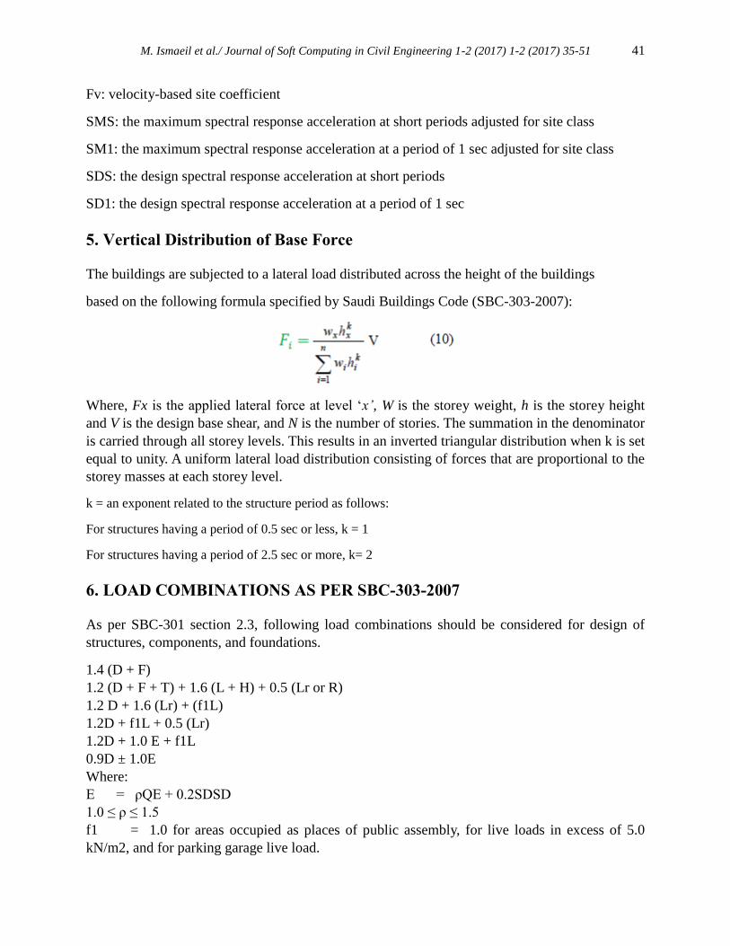
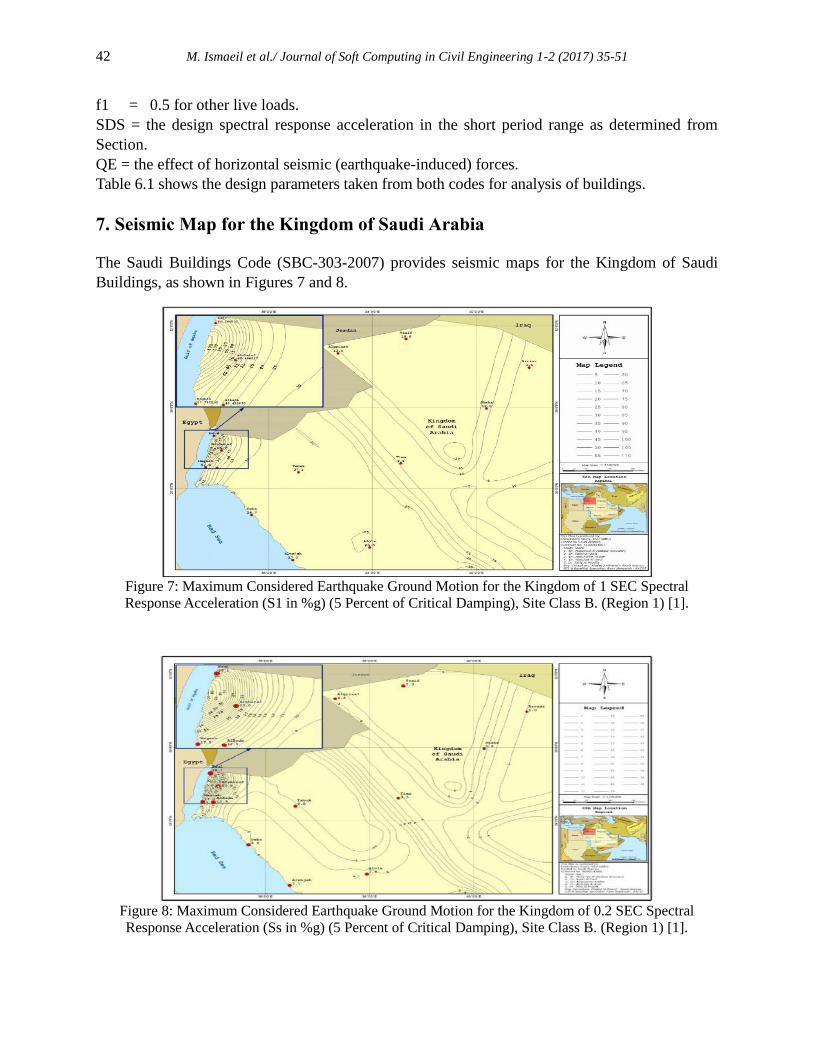
7. Seismic Map for the Kingdom of Saudi Arabia
The Saudi Buildings Code (SBC-303-2007) provides seismic maps for the Kingdom of Saudi
Buildings, as shown in Figures 7 and 8.
Figure 7: Maximum Considered Earthquake Ground Motion for the Kingdom of 1 SEC Spectral
Response Acceleration (S1 in %g) (5 Percent of Critical Damping), Site Class B. (Region 1) [1].
Figure 8: Maximum Considered Earthquake Ground Motion for the Kingdom of 0.2 SEC Spectral
Response Acceleration (Ss in %g) (5 Percent of Critical Damping), Site Class B. (Region 1) [1].
M. Ismaeil et al./ Journal of Soft Computing in Civil Engineering 1-2 (2017) 1-2 (2017) 35-51 43
8. Mapped acceleration parameters
The design parameters that are used in the equivalent static method are illustrated as following:
The parameters Ss and S1 shall be determined from the 0.2 and 1 second spectral response
accelerations shown on country maps
Where S1 is less than or equal to 0.04 and Ss is less than or equal 0.15, the structure is permitted
to be assigned to seismic design category A So,
S1= the mapped spectral accelerations for a 1- second period
Ss= the mapped spectral accelerations for short period.
On lack of a map of spectral accelerations of S1 and SS, the following can be assumed:
S1= 1.25 Z, Ss= 2.5 Z (amendment no. 3 to SI 413 (2009)) or from maps as shown in
Figures 7 and 8.
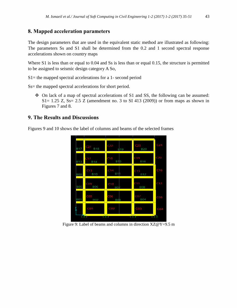
9. The Results and Discussions
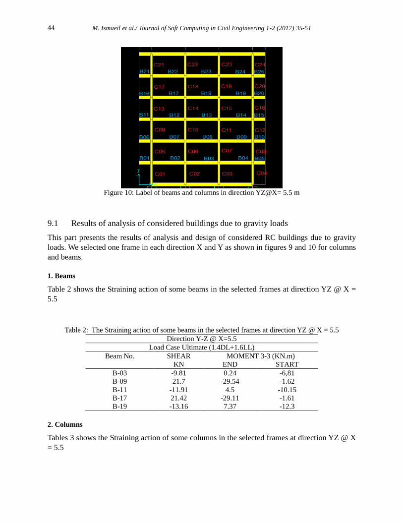
Figures 9 and 10 shows the label of columns and beams of the selected frames
Figure 9: Label of beams and columns in direction XZ@Y=9.5 m
44 M. Ismaeil et al./ Journal of Soft Computing in Civil Engineering 1-2 (2017) 35-51
Figure 10: Label of beams and columns in direction YZ@X= 5.5 m
9.1 Results of analysis of considered buildings due to gravity loads
This part presents the results of analysis and design of considered RC buildings due to gravity
loads. We selected one frame in each direction X and Y as shown in figures 9 and 10 for columns
and beams.
1. Beams
Table 2 shows the Straining action of some beams in the selected frames at direction YZ @ X =
5.5
Table 2: The Straining action of some beams in the selected frames at direction YZ @ X = 5.5
Direction Y-Z @ X=5.5
Load Case Ultimate (1.4DL+1.6LL)
Beam No. SHEAR MOMENT 3-3 (KN.m)
KN END START
B-03 -9.81 0.24 -6,81
B-09 21.7 -29.54 -1.62
B-11 -11.91 4.5 -10.15
B-17 21.42 -29.11 -1.61
B-19 -13.16 7.37 -12.3
2. Columns
Tables 3 shows the Straining action of some columns in the selected frames at direction YZ @ X
= 5.5
M. Ismaeil et al./ Journal of Soft Computing in Civil Engineering 1-2 (2017) 1-2 (2017) 35-51 45
Table 3: The Straining action of some columns in the selected frames at direction YZ @ X = 5.5
Direction Y-Z @ X=5.5
Load Case Ultimate (1.4DL+1.6LL)
Column No. AXIAL SHEAR MOMENT 3-3 (KN.m)
KN END START
C-01 -907.8 -0.61 -0.62 -2.57
C-03 -1307.75 -10.94 21.51 -13.51
C-09 -586.33 0.56 -1.46 -0.33
C-11 -855.93 -15.98 26.44 -24.68
C-17 -285.18 0.63 -1.17 0.84
C-19 -421.77 -11.1 18.29 -17.22
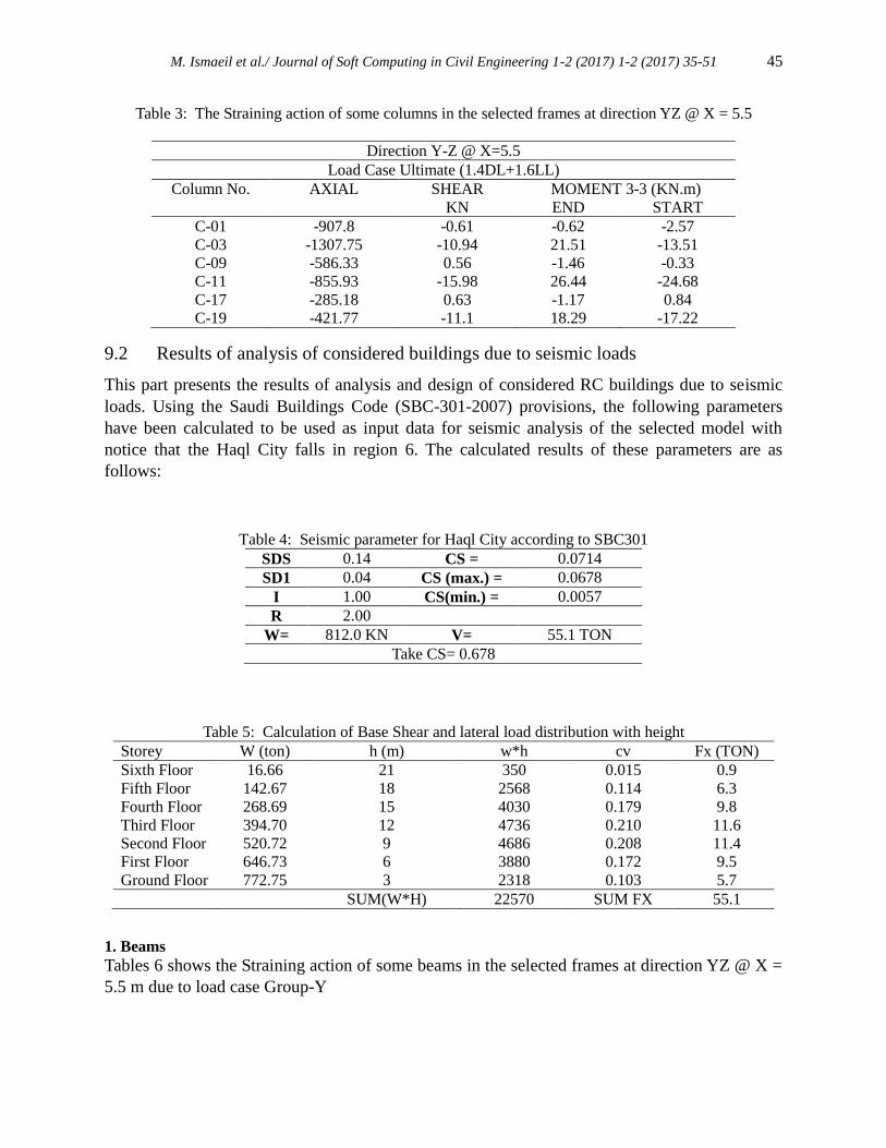
9.2 Results of analysis of considered buildings due to seismic loads
This part presents the results of analysis and design of considered RC buildings due to seismic
loads. Using the Saudi Buildings Code (SBC-301-2007) provisions, the following parameters
have been calculated to be used as input data for seismic analysis of the selected model with
notice that the Haql City falls in region 6. The calculated results of these parameters are as
follows:
Table 4: Seismic parameter for Haql City according to SBC301
SDS 0.14 CS = 0.0714
SD1 0.04 CS (max.) = 0.0678
I 1.00 CS(min.) = 0.0057
R 2.00
W= 812.0 KN V= 55.1 TON
Take CS= 0.678
Table 5: Calculation of Base Shear and lateral load distribution with height
Storey W (ton) h (m) w*h cv Fx (TON)
Sixth Floor 16.66 21 350 0.015 0.9
Fifth Floor 142.67 18 2568 0.114 6.3
Fourth Floor 268.69 15 4030 0.179 9.8
Third Floor 394.70 12 4736 0.210 11.6
Second Floor 520.72 9 4686 0.208 11.4
First Floor 646.73 6 3880 0.172 9.5
Ground Floor 772.75 3 2318 0.103 5.7
SUM(W*H) 22570 SUM FX 55.1
1. Beams
Tables 6 shows the Straining action of some beams in the selected frames at direction YZ @ X =
5.5 m due to load case Group-Y

46 M. Ismaeil et al./ Journal of Soft Computing in Civil Engineering 1-2 (2017) 35-51
Table 6: The Straining action of some beams in the selected frames at direction YZ @ X = 5.5 m due to
load case Group-Y
Direction Y-Z @ X=5.5 m
Load case: GroupY
Beam No. SHEAR MOMENT 3-3 (KN.m)
KN END START
B-03 53.39 -93.73 90.13
B-09 22.07 -30.12 -1.65
B-11 49.02 -86.03 82.88
B-17 21.78 -29.68 -1.64
B-19 32.05 -52.51 49.84
Where:
Load Case Group-Y is load combination included seismic loads at Y direction.
Load Case Ultimate is load combination included dead and live loads only
2. Columns
Tables 7 shows the Straining action of some columns in the selected frames at direction YZ @ X
= 5.5 m
Table 7: The Straining action of some Columns in the selected frames at direction YZ @ X = 5.5 m due to
load case Group-Y
Direction Y-Z @ X=5.5
Load Case: GroupY
Column No. AXIAL SHEAR MOMENT 3-3 (KN.m)
KN END START
C-01 -922.95 1.23 -2.68 -2.62
C-03 -1331.32 -11.18 21.93 -13.8
C-09 -596.12 1.74 -3.28 2.3
C-11 -871.43 -18.32 27.01 -25.21
C-17 -289.96 0.74 -1.33 1.04
C-19 -429.44 -11.33 18.68 -17.59
10. Design of structural elements against gravity loads
The reinforced concrete sections were designed according to the BSI 8110 [9] using the limit
state design method (Mosley and Bungey, 1997) [10].
10.1. Design of columns
(a) Calculation of internal forces in columns
The columns were designed to resist axial compression forces and bending moment due to
gravity load. The design forces in columns obtained from the computer analysis program
SAP2000 are shown in Table 8.
*Direction YZ@X=5.5
M. Ismaeil et al./ Journal of Soft Computing in Civil Engineering 1-2 (2017) 1-2 (2017) 35-51 47
Table 8: Internal forces in columns due to gravity loads.
Column No. Output Case Shear Force (KN) Bending Moment (KN.m) Axial Force (KN)
C04 1.4DL+1.6LL 11.26 13.99 1372.02
C03 1.4DL+1.6LL 10.94 13.51 1307.75
C02 1.4DL+1.6LL 1.64 3.78 997.52
C01 1.4DL+1.6LL -0.61 2.57 907.80
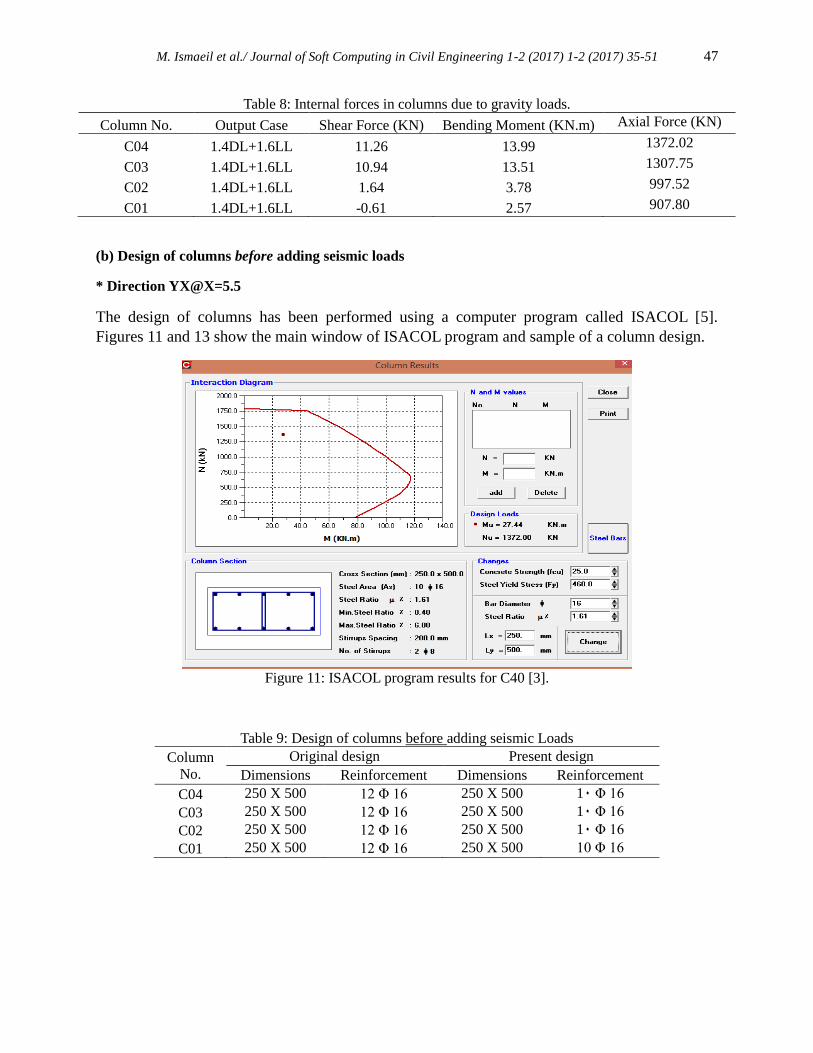
(b) Design of columns before adding seismic loads
* Direction YX@X=5.5
The design of columns has been performed using a computer program called ISACOL [5].
Figures 11 and 13 show the main window of ISACOL program and sample of a column design.
Figure 11: ISACOL program results for C40 [3].
Table 9: Design of columns before adding seismic Loads
Column
No.
Original design Present design
Dimensions Reinforcement Dimensions Reinforcement
C04 250 X 500 12 Φ 16 250 X 500 10 Φ 16
C03 250 X 500 12 Φ 16 250 X 500 10 Φ 16
C02 250 X 500 12 Φ 16 250 X 500 10 Φ 16
C01 250 X 500 12 Φ 16 250 X 500 10 Φ 16
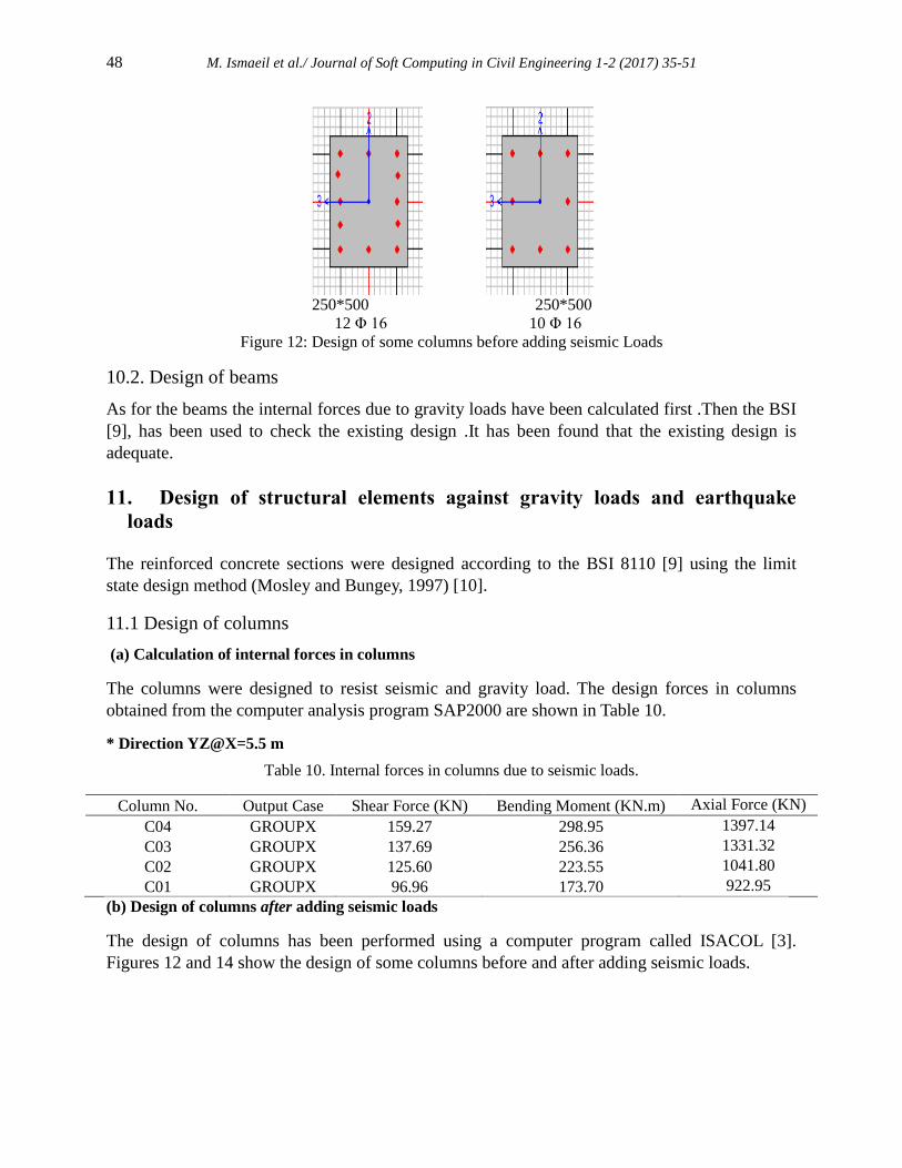
48 M. Ismaeil et al./ Journal of Soft Computing in Civil Engineering 1-2 (2017) 35-51
250*500 250*500
12 Φ 16 10 Φ 16
Figure 12: Design of some columns before adding seismic Loads
10.2. Design of beams
As for the beams the internal forces due to gravity loads have been calculated first .Then the BSI
[9], has been used to check the existing design .It has been found that the existing design is
adequate.
11. Design of structural elements against gravity loads and earthquake
loads
The reinforced concrete sections were designed according to the BSI 8110 [9] using the limit
state design method (Mosley and Bungey, 1997) [10].
11.1 Design of columns
(a) Calculation of internal forces in columns
The columns were designed to resist seismic and gravity load. The design forces in columns
obtained from the computer analysis program SAP2000 are shown in Table 10.
* Direction YZ@X=5.5 m
Table 10. Internal forces in columns due to seismic loads.
Column No. Output Case Shear Force (KN) Bending Moment (KN.m) Axial Force (KN)
C04 GROUPX 159.27 298.95 1397.14
C03 GROUPX 137.69 256.36 1331.32
C02 GROUPX 125.60 223.55 1041.80
C01 GROUPX 96.96 173.70 922.95
(b) Design of columns after adding seismic loads
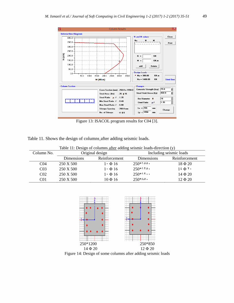
The design of columns has been performed using a computer program called ISACOL [3].
Figures 12 and 14 show the design of some columns before and after adding seismic loads.
M. Ismaeil et al./ Journal of Soft Computing in Civil Engineering 1-2 (2017) 1-2 (2017) 35-51 49
Figure 13: ISACOL program results for C04 [3].
Table 11. Shows the design of columns after adding seismic loads.
Table 11: Design of columns after adding seismic loads-direction (y)
Column No. Original design Including seismic loads
Dimensions Reinforcement Dimensions Reinforcement
C04 250 X 500 10 Φ 16 250*1550 18 Φ 20
C03 250 X 500 10 Φ 16 250*1250 14 Φ 20
C02 250 X 500 10 Φ 16 250*1200 14 Φ 20
C01 250 X 500 10 Φ 16 250*850 12 Φ 20
250*1200 250*850
14 Φ 20 12 Φ 20
Figure 14: Design of some columns after adding seismic loads
50 M. Ismaeil et al./ Journal of Soft Computing in Civil Engineering 1-2 (2017) 35-51
12. Conclusion
This paper provides set of seismic analysis and design of RC buildings located in the most active
seismic zone region in Saudi Arabia. The building was analyzed and designed before and after
considering earthquake loads applied in two directions; XX and YY. From the results obtained it
can be clearly seen that:
1. There are slight changes in the values of the bending moments and shear forces on the beams
before and after considering earthquake loads as shown in Tables 2 and 6. There is increase in
some internal beams, such as B-3, B-11 and B-19.
2. The values of the bending moments and shear forces on the columns due to seismic loads are
nearly five times that due to gravity loads as shown in Tables 8 and 10.
3. The values of the axial forces on the columns due to seismic loads are approximately similar
to gravity loads as shown in Tables 8 and 10.
4.As an overall trend the results showed that the current design of RC buildings located in the
most active seismic zone region of the Kingdom of Saudi Arabia, Haql city were found unsafe,
inadequate and unsatisfied to mitigate seismic loads.
The present study represents the first attempt to investigate the seismic resistance of residual
buildings in Haql city in Saudi Arabia. Due to the lack of knowledge about the seismic activity in
this country some buildings are designed and constructed without any seismic load
consideration. Seismicity of The Saudi Arabia may be considered as moderate. Hence, all
buildings should be checked against earthquake resistance. The present paper proposes a simple
procedure to check the seismic resistance of such buildings.
The obtained results emphasize the following conclusions:
1- Current design of some residual buildings in the Saudi Arabia does not consider earthquake loads.
2- It has been found that the current design of residual buildings in the Haql city is unsafe for the
current seismicity of the Haql city.
Acknowledgements
The author would like to express his gratitude to King Khalid University, Saudi Arabia for
providing administrative and technical support.
REFERENCES
[1] Saudi Building Code SBC-301-2007: Loads and Forces Requirements, Saudi Buildings Code National
Committee (2007).
[2] Computers and Structures. (2001). SAP2000: Three Dimensional Static and Dynamic Finite
ElementAnalysisand Design of Structures, Computers and Structures Inc., Berkeley, California,
U.S.A
M. Ismaeil et al./ Journal of Soft Computing in Civil Engineering 1-2 (2017) 1-2 (2017) 35-51 51
[3] Shehata , A .Y. "Information Systems Application On Reinforced Concrete Columns", M.Sc. Thesis,
Faculty of Engineering , Department of Structural Engineering , Cairo University , Giza , Egypt ,
1999 .
[4] https://en.wikipedia.org/wiki/1995_Gulf_of_Aqaba_earthquake
[5] Saleh Mahmoud A. Attar ‘Evaluation of the seismic performance of a typical school building’, Thesis
(M.Sc.), King Abdul-Aziz University, 2003.
[6] AL-Haddad, M., Siddiqi, G.S., Al-Zaid, R., Arafah, A., Necioglu, A., and Turkelli, N., " A Study
Leading to a Preliminary Seismic Design Criteria, for the Kingdom," Final Report, KACST project
No. AR-9-31, Riyadh, 1992.
[7] Al-Haddad, M., Siddiqi, G.S., Al-Zaid, R., Arafah, A., Necioglu, A., and Turkelli, N., “A Basis for
Evaluation of Seismic Hazard and Design Criteria for Saudi Arabia”, Journal of Earthquake
Engineering Research Institute, EERI, Spectra, Vol. 10, No. 2, May 1994, Okland, California.
[8] M. A. Ismaiel et.al. (2017) Seismic Analysis of a Ten-Storey Reinforced Concrete Building in Jazan
Area, KSA. Open Journal of Civil Engineering, 7, PP. 252-266. http://www.scirp.org/journal/ojce/.
DOI: 10.4236/ojce.2017.72016
[9] BS 8110. (1997). the Structural Use of Concrete, British Standard Institution, London..
[10] Mosley, W. H. and Bungey, J. H. (1997): Reinforced Concrete Design; BS 8110:Part 1, 2nd Ed.
Macmillan , London.