sediment extraction and flow structure of vortex...
TRANSCRIPT
6th National Congress on Civil Engineering, April 26-27, 2011, Semnan University, Semnan, Iran
Sediment Extraction and Flow Structure of Vortex Settling Basin
J. Chapokpour 1, J. Farhoudi 2
1- Post Graduate Student, Hyd. Structures, Dept. of Irrigation Eng., Faculty of agricultural technology and engineering, UTCAN, University of Tehran, Iran, Email: [email protected]
2- Professor, Hyd. Structures, Dept. of Irrigation Eng., Faculty of agricultural technology and engineering., UTCAN, University of Tehran, Iran, E-mail: [email protected]
Corresponding Author’s E-mail:[email protected]
Abstract
The paper presents the results of an investigation conducted in a vortex chamber and the flow structure along with sediment extraction efficiency were observed. During the experiments, various flow discharges were employed. Three sizes of sediment were fed at three different rates. It was observed that the increase in the flow and sediment feeding rates result in the increase of sediment extraction efficiency of the settling basin. An ADV velocity measuring equipment was utilized to determine flow structure inside the settling basin. It was also found that various types of flow patterns were developed in radial sections which may play a positive or negative role in sediment trapping process. Keywords: Sediment extraction; vortex chamber; extraction efficiency; flow structure.
1. INTRODUCTION Sediment deposition in diversion canals is one of the most severe problems which the designers and operators are often faced with. Sediment laden flows are capable to transport and deposit a considerable rate of sediment loads in the conveyance channels which results in reduction of conveyance capacity of the system. Different types of sediment extractors/excluders, such as tunnel type, vortex tubes, rectangular settling basins and vortex type settling basins are often employed for this purpose. The vortex settling basin (VSB), is a continuous device which applies a certain fraction of flow for flushing the sediment particles out of the diverted stream (Gard and Ranga raju, 2000). Classical settling basins generally suffer from two main disadvantages: (i) requirement of large dimensions of basin compared with other types, and (ii) longer settling time for sediment particles. Sediment extractors of vortex type would overcome the mentioned disadvantages (Keshavarzi and Gheisi, 2006). VSB utilizes centrifugal forces to generate a vortex motion around its central axis to remove sediment particles from the incoming flow by means of secondary currents in the chamber through the central flushing orifice (Ziaei, 2000). In this device the high velocity flow is introduced tangentially into cylindrical basin having an orifice at the center of its bottom. This gives rise to the combined vortex conditions (Rankine type) having a forced vortex near the orifice and a free vortex at the outer region towards the periphery of the basin. As a result, sediment concentration gradient builds up across the vortex and a diffusive flux, proportional but opposite to the centrifugal flux, is induced (Athar et al., 2002). Resulting secondary flow causes the flow layers adjacent to the floor of the basin moving towards the central outlet orifice. Therefore, the sediment particles reaching the center of the chamber could be flushed out continuously through the orifice and a relatively sediment free water would leave the basin through its overflow weir crest (Mashuri, 1986). The vortex settling basins have been investigated principally by Vokes and Jenkines (1943), Velioglu (1972), Salakhov (1975), Cecen and Bayazit (1975), Sulivan et al. (1978), Curi et al. (1979), Mashuri (1981,1986), Svarovski (1981), Ogihara and Sakagouchi (1984), Sanmogantan (1985), Zhou et al. (1989, 1997), Paul et al. (1991), Ziaei (2000, 2001), Athar et al. (2002, 2003), Keshavarz and Gheisi (2006). In the present study, the diaphragm and the deflector were eliminated to solve the problem of sediment deposition on their top surfaces. Despite the other investigators, the height of the entrance orifice was decreased by 30% which resulted in a high velocity of entrance flow jet. A strip type sediment feeder was employed throughout the experiments to overcome the disadvantages of unsteady feeding and point feeding of sediments recommended by the previous researches.
6th National Congress on Civil Engineering, April 26-27, 2011, Semnan University, Semnan, Iran
2
To understand the flow structure, in horizontal and radial sections of the basin, a series of flow measurement readings were recorded.
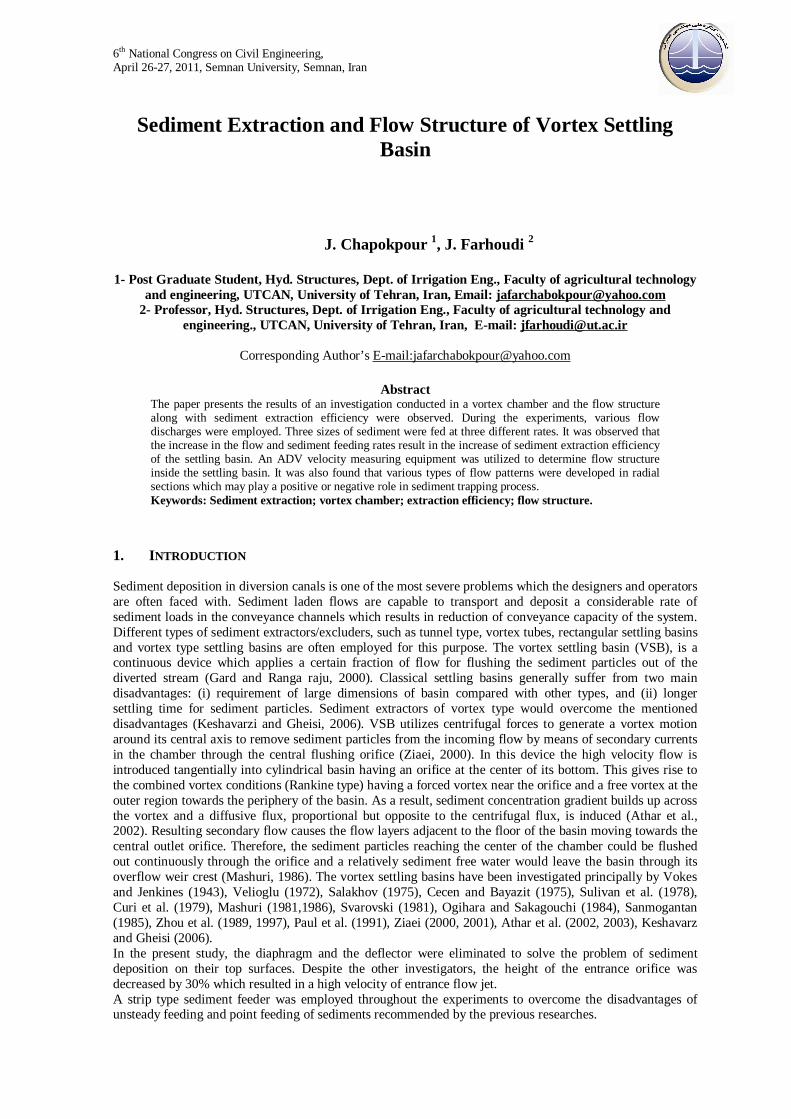
1. EXPERIMENTAL LAYOUT AND METHODOLOGY The experiments were carried out in a physical model of the vortex settling basin with the characteristics shown in Table 1 and schematically depicted in Fig. 1.
Figure 1. Schematic layout and parameters of vortex settling basin, used in the research.
Table 1. Characteristics of settling basin Height of chamber
H(m)
Diameter of central orifice do(m)
Type of overflow
weir L1 (m)
Diameter of chamber
d (m)
Basin depth at periphery
h2 (m)
Width of inlet channel
B(m)
Length of inlet
channel (m)
Slope of inlet channel
S %
0.7 0.075 circular overflow weir with
crest length of 0.8
1.5 0.06 0.3 6 0.045
6th National Congress on Civil Engineering, April 26-27, 2011, Semnan University, Semnan, Iran
3
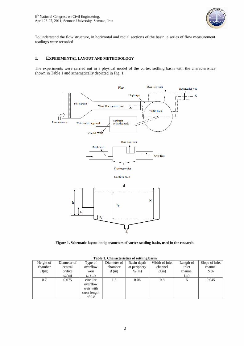
The tests were performed in a configuration in which the angular distance of inlet and overflow outlet was 0 degree as recommended by Paul et al. (1991). To maintain a tangential inlet flow jet in the vortex basin, a diaphragm was installed across the entrance channel at a level of 0.12m from the canal bed. Water was then supplied from a constant head tank connected through upstream stilling tank to the circulating water supply system of the laboratory where the incoming flow was regulated by means of a turning valve. Precautions were made to avoid large eddies and disturbances at the free surface of water in upstream stilling tank. Also some fiber bags were used for collection of the sediment particles as proposed by Keshavarzi and Gheisi (2006). The discharge from overflow weir and flushing orifice were measured by means of a pre-calibrated sharp crested rectangular weir and a V-notch respectively. An Acoustic Doppler Velocity Meter (ADV) was used to measure the flow velocities in three dimensions to determine the dominant secondary currents inside of the vortex basin. The velocities were measured in eight radial sections at intervals of 45° from the origin. At each radial section 56 points were selected in a grid of velocity measurement, as demonstrated in Fig. 2, resulting in a total of 448 measuring points inside the chamber.
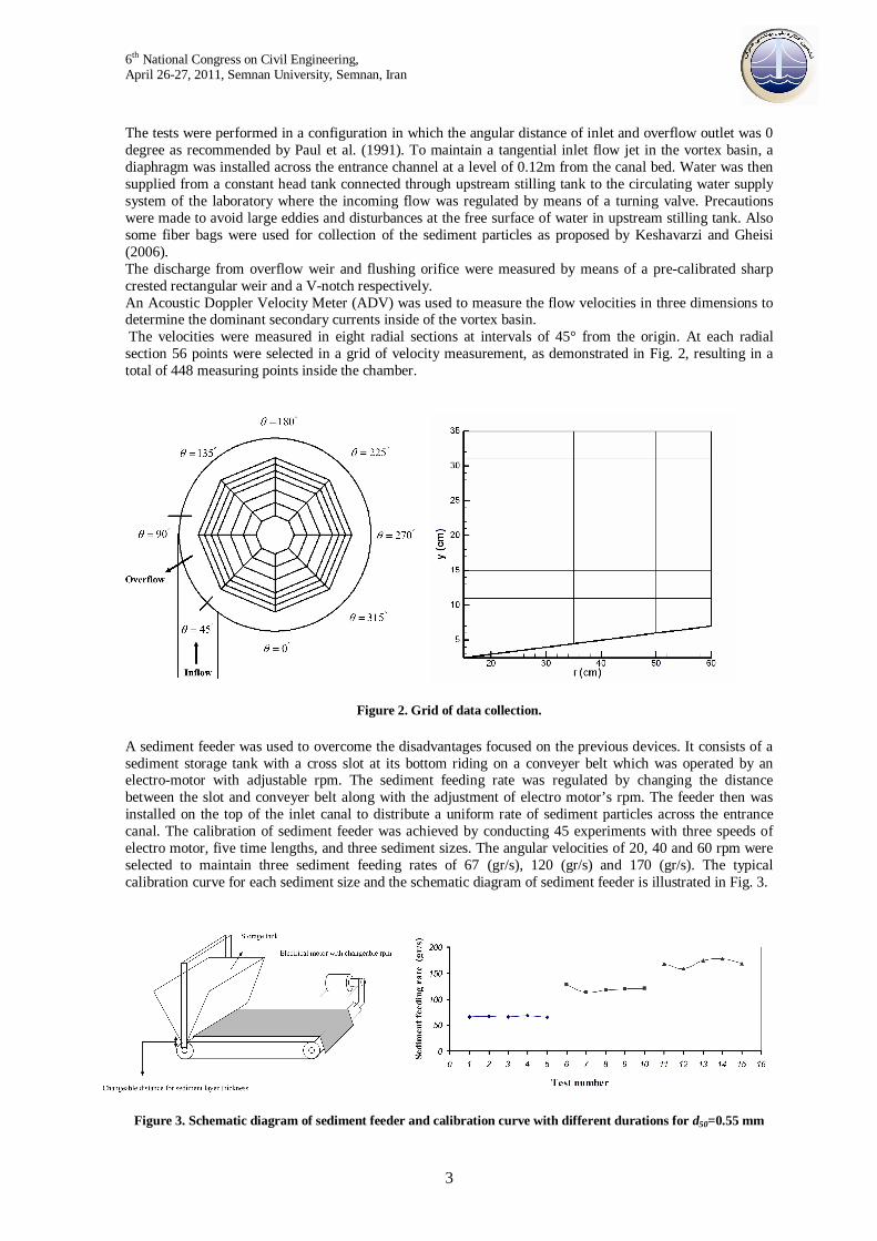
Figure 2. Grid of data collection. A sediment feeder was used to overcome the disadvantages focused on the previous devices. It consists of a sediment storage tank with a cross slot at its bottom riding on a conveyer belt which was operated by an electro-motor with adjustable rpm. The sediment feeding rate was regulated by changing the distance between the slot and conveyer belt along with the adjustment of electro motor’s rpm. The feeder then was installed on the top of the inlet canal to distribute a uniform rate of sediment particles across the entrance canal. The calibration of sediment feeder was achieved by conducting 45 experiments with three speeds of electro motor, five time lengths, and three sediment sizes. The angular velocities of 20, 40 and 60 rpm were selected to maintain three sediment feeding rates of 67 (gr/s), 120 (gr/s) and 170 (gr/s). The typical calibration curve for each sediment size and the schematic diagram of sediment feeder is illustrated in Fig. 3.
Figure 3. Schematic diagram of sediment feeder and calibration curve with different durations for d50=0.55 mm
6th National Congress on Civil Engineering, April 26-27, 2011, Semnan University, Semnan, Iran
4
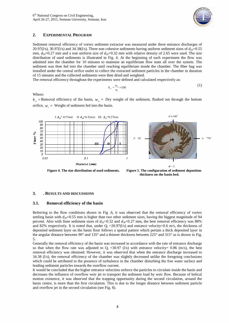
2. EXPERIMENTAL PROGRAM Sediment removal efficiency of vortex sediment extractor was measured under three entrance discharges of 20.97(l/s), 30.97(l/s) and 34.38(l/s). Three non cohesive sediments having uniform sediment sizes of d50=0.55 mm, d50=0.27 mm and a non uniform size of d50=0.32 mm with relative density of 2.65 were used. The size distribution of used sediments is illustrated in Fig. 4. At the beginning of each experiment the flow was admitted into the chamber for 10 minutes to maintain an equilibrium flow state all over the system. The sediment was then fed into the chamber until reaching equilibrium inside the chamber. The fiber bag was installed under the central orifice outlet to collect the extracted sediment particles in the chamber in duration of 15 minutes and the collected sediments were then dried and weighted. The removal efficiency throughout the experiments were defined and calculated respectively as:
100×=i
oo ω
ωη
(1)
Where: =oη Removal efficiency of the basin, =oω Dry weight of the sediment, flushed out through the bottom
orifice, =iω Weight of sediment fed into the basin.
Figure 4. The size distribution of used sediments. Figure 5. The configuration of sediment deposition
thickness on the basin bed. 3. . RESULTS AND DISCUSSIONS 3.1. Removal efficiency of the basin
Referring to the flow conditions shown in Fig .6, it was observed that the removal efficiency of vortex settling basin with d50=0.55 mm is higher than two other sediment sizes, having the biggest magnitude of 94 percent. Also with finer sediment sizes of d50=0.32 and d50=0.27 mm, the best removal efficiency was 88% and 82% respectively. It is noted that, under Qi =20.97(l/s) and entrance velocity=0.6 m/s, the thickness of deposited sediment layer on the basin floor follows a spatial pattern which pertain a thick deposited layer in the angular distance between 90° and 135° and a thinner thickness between 225° and 315° as is shown in Fig. 5. Generally the removal efficiency of the basin was increased in accordance with the rate of entrance discharge so that when the flow rate was adjusted to Qi =30.97 (l/s) with entrance velocity= 0.86 (m/s), the best removal efficiency was obtained. However, it was observed that when the entrance discharge increased to 34.38 (l/s), the removal efficiency of the chamber was slightly decreased unlike the foregoing conclusions which could be attributed to the presence of turbulence in the chamber disturbing the free water surface and leading sediment particles towards the overflow current. It would be concluded that the higher entrance velocities enforce the particles to circulate inside the basin and decreases the influence of overflow weir jet to transport the sediment load by weir flow. Because of helical motion existence, it was observed that the trapping opportunity during the second circulation, around the basin centre, is more than the first circulation. This is due to the longer distance between sediment particle and overflow jet in the second circulation (see Fig. 8).

6th National Congress on Civil Engineering, April 26-27, 2011, Semnan University, Semnan, Iran
5
It was also observed that, the removal efficiency of the basin was increased as the sediment feeding rates increased from 67 to 170 (gr/s).
3.2. Flow characteristics
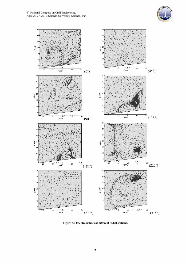
Secondary currents were generated in the vortex settling basin as a consequences of the effects raised from (i) entering water jet, (ii) over fall water jet from the curved weir crest and (iii) the bed slope of the basin towards the central orifice. To realize the characteristics of secondary currents in radial sections and its influences on removal efficiency, the velocity measurements in radial sections were analyzed and streamlines depicted in Fig. 7 from which the followings outlines could be mentioned:
• At the radial section of 0°, the dominant vortex is in clockwise direction mood and located between radial distances of 0 to 50cm from the center of basin. This vortex, with a circulation tendency towards the central air core and flushing pipe, had a great influence on the sediment movement near the bed floor trapping nearly all sediment particles there. On the other hands, in the regions near to sidewall a weak tendency for anticlockwise (vortex) was observed.
Figure 6. Removal efficiency of vortex settling basin under three sediment feeding rates and three flow discharges.(a) uniform grain size with d50 =0.55mm. (b) non uniform grain size with d50 =0.32mm.
(c) uniform grain size with d50 =0.27mm.

6th National Congress on Civil Engineering, April 26-27, 2011, Semnan University, Semnan, Iran
6
• In the radial section of 45°, clockwise vortex was disappeared. • In the radial section of 90°, anticlockwise vortex is generated. In this section the streamlines
followed by the anticlockwise vortex with its direction from center to the sidewall. Consequently, the sediment particles were moved from the centre of basin towards the sidewall depositing denser sediment layer adjacent to the wall.
• In the radial section of 135°, the powerful center of anticlockwise vortex is located at the lower depths having a dominant propagation of currents towards the central air core.
• In the radial section of the 180°, the secondary currents generally were extended towards the central air core showing the circulation of weak anticlockwise vortex and a sink near the basin bed.
• At the radial section of 225°, propagation of currents in the direction of water surface was noted where a circulating anticlockwise vortex core existed between radial distance of 45 to 55cm.
• At the radial section of 270°, it was found that the anticlockwise vortex diminished and currents were dominantly extended towards the central air core.
• At the radial section of 315°, the generation of a sink-vortex was observed, having clockwise circulation absorbing most of the streamlines with a positive role in trapping of sediments particles.
Based on the above mentioned analyzes in considering the generation, extension ,weakening and directions of flow patterns it was found that at the region of 225° to 315°, the highest trapping action was performed which falls in a good agreement with experimental observations for sediment deposition in the basin. The tangential and radial velocities were measured and analyzed from which the velocity vectors and flow streamlines were constructed at superimposed horizontal sections as is depicted in Fig. 8 (4 typical sections are showed), where the vertical distance between two consecutive sections was 4 cm. Generally it was found that the direction of streamlines are towards the side wall of basin in lower sections which tends the sediment particles travel a longer path towards the central orifice as bed load. Whereas, in the upper sections, the sediment particles take a shorter paths towards the central air core as suspended load. Two dimensional velocity vector analysis in the horizontal sections, showed that the velocity adjacent to zones of central air core is higher than those on other zones maintain a constant magnitude near the side walls of the chamber. Despite to this observation, at the radial line of 90° from origin and zones near the entrance flow jet, velocity vectors were influenced by entrance flow jet showing an increasing magnitude by nearing to the sidewall. 4. CONCLUSIONS In general, by increasing the entering discharge and sediment feeding rate the removal efficiency of the basin becomes larger. Therefore, unlike classical settling basins the vortex settling basin needs for higher inlet velocity to maintain a higher efficiency. Decreasing the level of entrance orifice by 30% from that of proposed by Paul et al. (1991), increases the entrance velocity, without having a deflector, which would result in a solution for the problem of sediment deposition on the top surface of deflector. An increase in the incoming velocity generates a powerful centrifugal forced vortex causing a better formation of central air core with smaller flushing ring diameter which results in higher hydraulic efficiencies of the basin. Based on velocity analysis, it was noted that in the lower flow layers the sediment particles take a longer helical path towards flushing orifice with a higher concentration of sediment around flushing orifice, rather than upper flow layers. The secondary currents in radial sections have various flow patterns in the basin which may impose either positive or negative role in sediment trapping. Comparing the magnitude of velocity and streamlines path in horizontal sections with occurrence of secondary currants in radial sections, it was revealed that the flow in the main spiral direction plays a higher role on removal efficiency.
6th National Congress on Civil Engineering, April 26-27, 2011, Semnan University, Semnan, Iran
7
Figure 7. Flow streamlines at different radial sections.

6th National Congress on Civil Engineering, April 26-27, 2011, Semnan University, Semnan, Iran
8
Figure 8. Velocity vectors and flow streamlines at different superimposed horizontal sections (distance from central orifice are underlined).
5. REFERENCES
1. Athar, M., Kothyari, U.C. & Garde, R.J. (2002). Sediment removal efficiency of vortex chamber type sediment extractor. J. Hyd. Engng, ASCE 128, No. 2, pp. 1051-1059.
2. Cecen, K. & Bayazit, M. Some laboratory studies of sediment controlling structures calculation of load-controlling water intake structures for Mountain Rivers. Proceedings of the Ninth Congress of the ICID, Moscow, Soviet Union, 1975, pp. 107-110.
3. Keshavarzi, A.R. & Gheisi, A.R. (2006). Trap efficiency of vortex settling basin for exclusion of fine suspended particles in irrigation canals. J. Irrig. Drain. Engng. 55, No. 4, pp. 419-434.
4. Mashauri, D.A. Selection of settling basin for sediment removal. M.Sc. Engng. thesis, Tampere University of Technology, Tampere, Finland, 1981.
5. Ogihara, K. & Sakaguchi, S. New system to separate the sediment from the water flow by using the rotating flow. In Proceedings of Fourth Congress of the Asia and Pacific Division, International Association of Hydrological Research, Chiang Mai, Thailand, 1984, pp. 753-766.
6. Paul, T.C., Sayal, S.K., Sakhanja, V.S. & Dhillon, G.S. (1991). Vortex settling chamber design considerations. J. Hyd. Engng, 117, No. 2, pp. 172-189.
7. Salakhov, F.S. (1975). Rotational design and methods of hydraulic calculation of load-controlling water intake structures for mountain rivers. Proceedings of Ninth Congress of the ICID, Moscow, Soviet Union, pp. 151-161.
8. Velioglu, S.G .Vortex type sedimentation tank. M.Sc Engng. thesis, Bogasiqi University, Turkey, 1972.
9. Zhou, Z., Wang, C. and Hou, J. Model study on flushing cone with strong spiral flow. In Proceedings, 4th International Symposium on River Sedimentation, Beijing, 1989, pp. 1213–1219.
10. Ziaei, A.N., Javan, M. and Keshavarzi, A.L. A new feature of vortex settling basin (VSB). In Proceedings of International Conference on Hydraulic Structures, Kerman, Iran, 2001, vol. 3, pp. 41-54.