sediment and stormwater current technical practices current technical... · sediment and stormwater...
TRANSCRIPT

Sediment and Stormwater Current Technical Practices Maryland Department of Transportation State Highway Administration June 7, 2018
This document details the current technical practices that are used to review Maryland
Department of Transportation State Highway Administration (MDOT SHA) projects
submitted to the MDOT SHA Plan Review Division (PRD). Some of these practices may be
modified or supplemented when the MDOT SHA Sediment and Stormwater Technical
Procedures are approved by the Maryland Department of the Environment (MDE).

Sediment and Stormwater
Current Technical Practices
June 7, 2018
2
Erosion & Sediment Control The intent of this section is to provide a supplement to the “2011 Maryland Standards and
Specifications for Soil Erosion and Sediment Control” in support of design efforts for MDOT SHA
projects. Future revisions and modifications to the Standards and Specifications may result in a
conflict between this supplement and the current Standards and Specifications. The designer is
reminded that the Standards and Specifications are the overriding design document and sound
engineering judgment should be applied to all designs.
The supplemental information listed below is referenced by the section number in the Standards
and Specifications that it refers to:
Add the following to Section A-5.I, Content of the Erosion and Sediment Control Plan:
Design Data on Plans
Some erosion and sediment control (ESC) measures (e.g. temporary gabion outlet structures,
temporary stone outlet structures, traps, basins, etc.) require design data on the plans. For
temporary stone outlet structures (TSOS) and temporary gabion outlet structures (TGOS),
include: location and/or identification number (ID #), weir elevation, drainage area (DA) size,
required storage, and actual storage. The ESC plan should include grading contours for
sediment traps and basins. When excavation or additional grading is needed to achieve the
required storage volume behind a TGOS or TSOS, show the temporary contours or provide
enough information during plan review to demonstrate sufficient storage availability.
Standard Stabilization Note
All disturbed areas with slopes flatter than 2:1 must be stabilized with 4 inches of topsoil,
seed, and mulch. For slopes 2:1 or steeper, refer to the “MDOT SHA Landscape Design
Guide.”
Same Day Stabilization:
Same Day Stabilization (SDS) is not a standard ESC measure. It should be limited to small
areas where the ESC filtering practices provided in the “2011 Maryland Standards and
Specifications for Soil Erosion and Sediment Control” are not feasible or practical. The SDS
provision should also be limited to areas where the proposed work can be completed in a
single working day, including application of the permanent stabilization. In some instances,
temporary plastic sheeting may be used to protect multi-day SDS areas. Seed, straw, and/or
SSM are not acceptable methods to temporary stabilize an SDS work area that will be
disturbed the next day.
When a plan has an area that calls for same day stabilization, but the rest of the disturbance
has ESC measures, the limits of SDS need to be clearly identified on the plans. This can be
done with a bubble, shading, or hatching. If shading or hatching is used, the pattern should be
identified in the legend.
MDOT SHA projects that include limited amounts of disturbances, such as sidewalk
replacement or guard rail installation, often include a provision for same day stabilization in
lieu of installation and removal of sediment control devices. A note detailing the requirements
Sediment and Stormwater
Current Technical Practices
June 7, 2018
3
should be provided on the plans and referred to in the Sequence of Construction (SOC). If the
note allows for either same day stabilization or the installation of sediment control devices,
then the sediment control devices should be shown on the plan.
Removal (pulling) and resetting of W-Beam post and panel that does not require grading or
earth disturbance may be excluded from the Limit of Disturbance (LOD). Most end treatment
installation includes safety grading and should be included within the LOD. New installation
of guard rail and associated safety grading should be included within LOD. The LOD may be
shown on a typical section or detail and included in the SOC. If a typical LOD detail is used,
any LOD located within environmentally sensitive areas should still be shown individually on
the plans.
Add the following after Section A-5.I, Content of the Erosion and Sediment Control Plan, Item
H.6 (e):
(f) Details that deviate from the “2011 Maryland Standards and Specifications for Erosion and
Sediment Control” must be shown on the plans.
Add the following to Section B-1:
Stabilized Construction Entrance
In certain situations, a stabilized construction entrance (SCE) may not be required. This
special allowance is made for areas where it is either infeasible or inapplicable to provide an
SCE. A typical example would be when the work area is smaller than the disturbance that
would be created by an SCE. Where no SCE is provided, the contractor shall designate the
construction equipment that shall be allowed within the LOD. This equipment shall be kept
within the LOD until the proposed work is complete and shall have treads/tires cleaned prior
to leaving the LOD. The method of cleaning shall be specified by the contractor. Washing of
treads/tires requires an appropriate sediment filtering practice or capturing devise.
Rumble Pad
Pre-constructed rumble pads may be used instead of stabilized construction entrances
provided they are installed according to manufacturer’s recommendations and a sufficient
number of pads are installed to allow a minimum of four tire revolutions while on the pad.
More pads may be needed depending on site conditions. The plan shall specify that
accumulated materials be cleaned from the pads daily (or more often if necessary) and an
acceptable disposed method be specified on the plan or in the specification.
Add the following to Section B-4-4:
Temporary Stabilization
Disturbed areas that are to be paved shall be stabilized with graded aggregate base (GAB). All
other areas shall be stabilized according to MDOT SHA specification section 704.

Sediment and Stormwater
Current Technical Practices
June 7, 2018
4
Add the following to Section B-4-8:
Staging, storage and stockpile areas
Staging, storage and stockpile areas are typically identified and located by the contractor, but
in some cases, may be shown on the plans. The contractor is responsible for obtaining
approvals for off-site borrow or waste sites. Off-site borrow or waste sites require local,
county, and Soil Conservation District approvals if they are located on private property, PRD
approval if on MDOT SHA property, or MDE approval if on federal property or other State
property.
Add the following to Section D-4, Conditions Where Practice Applies:
The exit slope must be flat. If the slope exceeds 0%, then use “NRCS Design Guide MD #6
Riprap Design Methods” on riprap channel design and Isbasch equation.
http://www.nrcs.usda.gov/Internet/FSE_DOCUMENTS/nrcs144p2_025594.pdf
Other Supplemental Information:
Notice of Intent (NOI)
For projects with an earth disturbance of 1.0 acre or greater, a National Pollutant Discharge
Elimination System (NPDES) Individual Application or a Notice of Intent (NOI) to comply
with General Permit to Discharge Stormwater Associated with Construction Activities must
be completed online and approved by MDE prior to any earth disturbance.
Notice of Termination (NOT)
The online Notice of Termination must be completed by MDOT SHA Compliance personnel
or MDOT SHA responsible construction personnel before a project can be closed out.
Stormwater facility as-builts should be accepted by the Highway Hydraulics Division and the
Plan Review Division prior to the project closeout.
Material Removal by Pressure Washing
If a high-pressure water jet is to be used to remove concrete from existing structures, the
plans or specifications should direct the contractor to submit a plan for effluent collection,
removal, and off-site treatment. This activity may require an Industrial Discharge Permit
from MDE.
Scarifying Soils
Existing in-situ soils should be scarified below stormwater management best management
practices (BMPs). Suggested language for this note to the contractor is as follows: “Scarify
the soil surface with a backhoe, skid-steer, or tractor with ripping teeth, cultivator, disk
harrow, or other agricultural machinery. Scarify to a depth that will result in soil that is easy
to dig for at least the top 12”. Do not scarify within the drip line of existing trees to prevent
damage to surface feeder roots.”

Sediment and Stormwater
Current Technical Practices
June 7, 2018
5
Three Day Dry NOAA forecast
Three Day NOAA weather forecasts are “Dry” when the probability of precipitation during
each of the three consecutive days is less than 20%. National Weather Service precipitation
forecasts for a project location can be found on www.weather.gov. Follow the steps below:
1) Enter the city/state or the zip code into the top-left blank.
2) Scroll down the page to see the detailed forecast.
3) Obtain the numerical probability of precipitation (0-100%) by clicking on “Hourly
Weather Graph”.
4) The brown line on the third section of the graph shows the hourly probability of
precipitation.
5) To see this in a tabular form, instead of a graph, click "Tabular Forecast" near the
bottom right of the web page.

Sediment and Stormwater
Current Technical Practices
June 7, 2018
6
Stormwater Management The intent of this section is to provide clarifications to the current version of the 2000 Maryland
Stormwater Design Manual, Volumes I & II (Design Manual) for MDOT SHA projects. Sound
engineering judgment should be applied to all designs. The information listed below is referenced
by the section number in the Design Manual that it refers to:
Chapter 2, Section 2.1:
Based on the 2007 Stormwater Management Act and the revisions to Chapter 5 of the Design
Manual, the criterion for calculating Environmental Site Design Volume (ESDv) is now the
same statewide. Therefore, P=1.0 inch should be used statewide for water quality and Tables
5.3 should be used to determine statewide ESDv.
Chapter 2, Section 2.3 page 2.8, Clarification on Cpv requirements for Eastern Shore:
Based on the 2007 SWM Act and the revisions to Chapter 5 of the Design Manual, ESDv, and
therefore Channel Protection Volume (Cpv), is required for the Eastern Shore. There are
multiple Cpv waivers that Eastern Shore projects may qualify for due to the prevalence of
tidal water. However, Chesapeake Bay Critical Area Regulations may require full ESDv on
Eastern Shore. Critical Area required management cannot be waived by PRD.
Chapter 2, Section 2.4 and 2.5, The following is a clarification to information provided on page
2.12, and 2.13 of the manual:
Existing agricultural land uses within the project LOD should be modeled as meadow in good
condition in the existing condition.
Existing agricultural land uses that are outside the LOD should be modeled as the present land
use in both the existing and proposed conditions.
Downstream impacts should be identified and addressed when culverts are enlarged as part of
a development project. See Sections 4.1.C and 4.2.C in the “MDOT SHA Sediment and
Stormwater Guidelines and Procedures – Part A” (Guidelines).
Chapter 3, Section 3.1.1 page 3.8, Additional guidance on feasibility:
Dry detention facilities may be used to provide quantity management (Qp2, Qp10, or Qf100).
Wet ponds are not permitted in Use III and IV Waters, or within 4 miles of airports.
Watershed and Stream Use information can be obtained from the following web sites:
Interactive 6 and 8 Digit Watershed Map:
https://data.maryland.gov/Energy-and-Environment/Maryland-s-8-Digit-Sub-
Watersheds/e9j9-vuxg/data

Sediment and Stormwater
Current Technical Practices
June 7, 2018
7
Interactive Stream Use Map:
http://mde.maryland.gov/programs/Water/TMDL/WaterQualityStandards/Pages/Designat
edUsesMaps.aspx
Chapter 5, Section 5.1.3.1:
Loss of water quality applies to both new development and redevelopment projects when an
existing system that provides water quality is altered. It should be evaluated throughout the
design development process. Changing a roadway from open section to closed section is only
considered to be a loss of water quality (LOWQ) if the existing roadside swale has an MDOT
SHA BMP number.
If the area to be developed was providing stormwater management (SWM) in existing
conditions for an adjacent drainage area within MDOT SHA right-of-way (ROW) or through
an agreement where MDOT SHA accepted responsibility for providing management, then the
management being lost must be replaced. If a new BMP replaces an existing BMP or other
SWM feature, such as a grass channel or disconnection, the new BMP must be designed to
replace the existing management in addition to satisfying the proposed management
requirements.
Chapter 5, Section 5.1.3.1:
A discussion of the erosion & sediment control approach should be included in the Concept
SWM narrative.
Chapter 5, Section 5.2, page 5.17:
The manual refers to and encourages the use of “treatment trains” as part of an overall system
for meeting the project’s stormwater water requirements. A minimum PE of 1 inch needs to
be treated by ESD, but it does not have to be attained in a single facility. It is acceptable to
provide practices in parallel or in series. For example, a treatment train of three bioswales is
essentially the same as a single bioswale with three separate segments or units for ESDv. The
facilities are connected, and one drains to the other, but each individual unit has a sub-drainage
area that drains directly to it.
For ESDv design purposes, the drainage area is the portion that drains directly to the individual
unit. If each unit in the treatment train is designed to treat the same level of PE from its
individual sub drainage area, there should be no overflow into the downhill unit during the
ESDv design storm, except for grass swales. However, if the PE treated varies from unit to
unit, the downhill facility will have to include overflow from the uphill facility for the ESDv
design storm. For quantity analysis (Qp), the drainage area is cumulative and gets
progressively larger for each downhill practice, as it does with a storm drain system. See the
Design Manual for design constraints for swales.

Sediment and Stormwater
Current Technical Practices
June 7, 2018
8
If the cumulative ESDv provided meets the target Pe and ESDv, then the ESDv treatment
provided by the treatment train is satisfactory. Water quality credit is not given for the portion
of PE above 1.0 inch, except for TMDL projects.
Add the following to Chapter 5, Section 5.2:
5.2.6: Impervious Area Requiring Treatment
The following procedure should be used for identifying, evaluating, and classifying POI/LOI
for MDOT SHA projects and calculating treatment requirements:
A. Identify the points of investigation (POIs) and lines of investigation (LOIs)
A POI must be identified at every location where concentrated runoff leaves the ROW. A
line of investigation (LOI) must be identified at every location where sheet flow leaves the
ROW. In some cases, it may be acceptable to place the POI where runoff leaves the LOD,
but this is unusual. If new points of concentrated flow are created or if there is a proposed
increase in peak flow, the applicant must obtain a letter from the adjacent property owner
acknowledging and accepting the impact(s) to his/her property. POIs with shifted drainage
area divides may result in increases in runoff and may have additional quantity
management requirements.
B. Determine Waiver Applicability
Areas that qualify for a 3.3.A waiver are not required to provide stormwater management.
If the entire POI qualifies for a 3.3.A waiver, there is no need to proceed with this process
for that POI, other than identifying the POI location.
C. Evaluate POIs
Provide a drainage area map delineating the drainage area to each POI for both existing
and proposed conditions. The drainage area, impervious area, time of concentration (Tc)
flow path, and runoff curve number (RCN) are required for each POI unless it qualifies for
a 3.3.A waiver.
D. Classify POIs
Calculate the percentage of existing impervious area (%I) for each POI. The area used for
calculating %I is the Stormwater Study Area (SSA) and will correspond to either the LOD
or ROW within the drainage area to the POI. The same method of calculating %I (LOD or
ROW) must be used for all POIs in the project. The designer should check the POI
classifications using both methods to determine the best choice for the project.
a. If I>40%, the POI is classified “redevelopment” and reconstructed areas require
50% WQ treatment and no Cpv is required. New impervious cover requires 100%
ESDv (WQv and Cpv).
b. If I≤40%, the POI is classified “new development”. Both reconstructed areas and
new impervious cover requires 100% ESDv (WQ and Cpv).

Sediment and Stormwater
Current Technical Practices
June 7, 2018
9
E. Calculate IART
LOD = Limit of Disturbance (acres)
Ai = Impervious area (acres)
Existing Ai = The total impervious area in the existing condition within the LOD(1)
Proposed Ai = The total impervious area in the proposed condition within the LOD(1)
ΔAi = Net change in Ai within the LOD (Proposed Ai – Existing Ai)(2)
I = Impervious cover (%)
(1) Exclude impervious area that is maintenance and qualifies for a 3.3.A waiver. Impervious areas associated
with isolated small foundations or posts for signs and lighting structures are considered de minimis and
should also be excluded from IART computations. Large structures and areas or concrete pads should be
included in IART calculations.
(2) This value will be negative when there is a net decrease in impervious area.
For Redevelopment POIs (I>40%):
IART = (Proposed Ai – Existing Ai) + 50% (Existing Ai), therefore:
IART = ΔAi + 50% (Existing Ai)
For New Development POIs (I≤40%):
IART = (Proposed Ai – Existing Ai) + (Existing Ai), therefore:
IART = Proposed Ai
The sum of impervious areas treated by all ESD facilities for water quality (PE=1.0”) must
equal or exceed IART. ESD facilities must be sized for the area draining to them. If the
project has excess WQv from ESD facilities or Chapter 3 bioretention facilities with a total
drainage area of less than 3 acres, it will be credited to the MDOT SHA Water Quality
Bank. Other Chapter 3 facilities may be used to treat project IART but may not be credited
to the WQ Bank.
Generally, when using the IART method, if IART ≤ 0 for a POI then stormwater management
treatment is not required for that POI. There are a few exceptions to this such as
improvements that generate no additional impervious area, but the disturbed area is expected
to be heavily compacted, or when the RCN is expected to increase in post development
condition. For those situations, the designer is expected to address SWM requirements using
the method of DA to POI (Table 5.3 in the SWM Manual).
Loss of water quality treatment (LOWQ) must be replaced or otherwise addressed.
F. Provide ESD to the MEP
ESDv
=(Pe)(Rv)(A)/12
Where: Pe = 2.6 for A or B soils
Pe = 2.2 for C soils
Pe = 2.0 for D soils
Rv = 0.95
A = ΔAi, for redevelopment POIs (I>40%)
A = Proposed Ai, for new development POIs (I≤40%)

Sediment and Stormwater
Current Technical Practices
June 7, 2018
10
ESDv is comprised of a water quality component (WQv and Rev) equivalent to the first
1.0 inch of PE and a channel protection component (Cpv) equivalent to the full target PE.
When the project includes redevelopment POI’s that have a combination of new
impervious and reconstructed impervious, it is necessary to calculate these components
separately.
Water Quality Volume (WQv)
ESD practices (Chapter 5 of the Design Manual) must be used to treat the WQv (Pe=1”).
Quality management does not have to be provided within the drainage area of the POI but
must be provided within the same six-digit watershed. WQv provided by a facility is
limited to the impervious area within the drainage area to the facility. For example, if the
impervious area draining to the facility is 0.3 acres, physically sizing the facility to treat
0.5 acres will not result in additional water quality credit.
If Chapter 5 practices are demonstrated to be impracticable, Chapter 3 facilities may be
used. However, a variance from providing ESD treatment for new development impervious
surfaces must be justified and approved by PRD for Chapter 3 facilities to be used. If both
Chapter 5 and Chapter 3 facilities are impracticable, a debit from the MDOT SHA Water
Quality bank may be used if there is sufficient credit for the watershed and the Highway
Hydraulics Division (HHD) approves the transaction. A debit from the WQ Bank satisfies
both WQv and Rev requirements for the debited acreage. Typically, WQ Bank debits are
intended for projects with a limited scope where IART requirements are minimal and there
are circumstances that preclude the use of SWM facilities, such as limited ROW, wooded
areas, karst, steep slopes, or urbanized corridors. Examples include Americans with
Disabilities Act (ADA) sidewalk projects, safety and resurfacing projects, and projects of
a similar nature.
Channel Protection Volume (Cpv)
This is the portion of ESDv that comes from “new” impervious area. It represents the
minimum volume that must be provided in the POI to satisfy the Cpv requirement. The
channel protection volume storage requirement must be met at each POI.
a. For POI’s that are classified as redevelopment (I>40%), Cpv is required for the
increase in impervious cover (ΔAi).
b. For POI’s that are classified as new development (I≤40%), Cpv is required for all
impervious area within the LOD (Proposed Ai).
Cpv requirements are calculated using the ESDv equation and are inclusive of the first 1”
for WQv. If the WQ Bank will be used to address the WQv requirements at a POI or the
WQ obligations will be satisfied elsewhere on the project, the required ESDv to satisfy
Cpv requirements at an individual POI is still the full target Pe and resulting ESDv for all
new development pavement (not the target Pe minus 1”). Additional treatment flexibility
can be granted if the WQv portion of the ESDv is satisfied elsewhere, since the selected
BMP would then not be required to have a WQ component. The total ESDv provided within
a POI should equal or exceed the required ESDv for that POI. It is allowable to provide
excess ESDv in one facility to compensate for a shortage of ESDv in another within the

Sediment and Stormwater
Current Technical Practices
June 7, 2018
11
same POI DA. The maximum ESDv is limited to the 1-year storm (2.6 inches). Criteria for
Cpv waivers is included in Section 3.3.B of the Guidelines.
ESD practices should be used to the maximum extent practicable to meet the Cpv portion
of the ESDv requirements. If ESD practices are provided for the first 1” Pe and Cpv cannot
be provided within an ESD facility, sufficient information shall be provided to demonstrate
why ESD practices are not feasible for providing Cpv. With sufficient justification and
PRD approval, structural practices (Chapter 3) may be used to meet the Cpv requirement.
When structural practices are used to address Cpv requirements, the Soil Conservation
Service (SCS) curve number methodology from Appendix D.11 should be used to calculate
the runoff volume that must be captured and managed by the structural practice. The reduce
curve number from Table 5.3 should be used in this methodology to include the quantity
management provided any ESDv treatment that partially treats the target Pe. The runoff
curve number (RCN) may be reduced for the 2-year peak discharge based on the amount
of rainfall treated by ESD practices within the POI.
Recharge Volume (Rev)
Rev requirements are determined based on the classification of the POI. If the POI is
classified as redevelopment (I>40%), recharge is required for the increase in impervious
area (ΔAi,) within the LOD. If the POI is classified as new development (I≤40%), recharge
is required for the entire impervious area within the LOD (Proposed Ai). If an ESD practice
has an underdrain and recharge is required for the contributing area, a storage reservoir
must be provided below the invert of the underdrain. If the WQ Bank is used to satisfy the
WQv requirements for a POI, the WQ Bank debit also satisfies the Rev requirement.
Impervious Area Shifts
If drainage areas are shifted as part of the project, include a description of the shifts in the
SWM report narrative. The MDOT SHA Impervious Area Shift Matrix table should be
used to present the impervious area shifts in a clear and concise manner. Quality and
quantity requirements for the shifted drainage area should be addressed as follows:
a. Quantity management requirements (Cpv/Qp/Qf) must be addressed at the POI
that area is being shifted to. This applies to shifted areas both inside and outside
the LOD.
b. Quality Management is also required if impervious area within the LOD is being
shifted.
i. The shifted impervious must be treated as new impervious in the POI it is
shifted to (Receiving POI).
ii. There may be a water quality credit in the POI it is shifting from (Giving
POI), depending on the development classification of that POI:
▪ New Development Giving POI’s receive no credit for the shifted
impervious area.
▪ Redevelopment Giving POI’s receive 50% credit for the shifted
impervious area.
Sediment and Stormwater
Current Technical Practices
June 7, 2018
12
G. Provide Qp and Qf
County requirements for Overbank Flood Protection Volume (Qp) and Extreme Flood
Protection Volume (Qf) are shown on Table 2 of the Guidelines. If peak management is
required, the proposed peak discharge rate must be equal to or lower than the existing peak
discharge rate for the applicable design storm. If the project proposes to remove an existing
quantity management BMP, the existing quantity management must be replaced. Peak
management of the 100-year storm event is required for POIs located in Inter-Jurisdictional
Flood Hazard Watersheds.
The Reduced Runoff Curve Number method is permitted for the 2-year analysis only. As
an alternative, HydroCAD or Haestad software may be used to route the 2-year or 10-year
storm through the SWM BMPs to demonstrate peak flow reduction for those storms.
Refer to Section 3.3.B of the Guidelines for a classification of POIs that are eligible for Qp
or Qf waivers. When a 3.3.B.3 waiver is applicable, a concurrence letter from the county
must be provided prior to Final Approval. If the POI discharges to private property,
concurrence from downstream property owner may be required. See Sections 4.1.C and
4.2.C of the Guidelines.
H. Stormwater Management Report
The Stormwater Management report and calculations should address the following:
a. Demonstrate that the impervious area treated (IAT) ≥ IART. This should be
evaluated for each watershed. WQv can be provided anywhere in the project as long
as it is in the same six-digit watershed.
b. Demonstrate that IART is treated for a PE of at least 1.0 inch in ESD facilities.
c. Demonstrate that the provided ESDv ≥ the required ESDv for each POI. If not,
discuss how the shortfall is being addressed.
d. Demonstrate that Cpv requirements have been addressed at each POI.
e. Demonstrate that Qp and Qf requirements been addressed at each POI.
f. Address the following for each outfall:
i. Discuss where each POI outfalls and what is downstream (open channel, pipe,
pond, dam, structure, etc.). If it flows to an open channel, demonstrate that it
is stable under existing conditions and the proposed velocities are non-
erosive. If it is not stable in existing conditions, discuss how this will be
addressed and whether proposed velocities have been designed to be at or
below existing velocities.
ii. If a new point of concentrated discharge is being created, discuss what
measures have been taken to prevent future erosion (level spreader, BMP,
etc.).
iii. Demonstrate that adequate outfall protection is provided.
iv. If the POI outfalls into a closed storm drain system, demonstrate, at a
minimum, there is available capacity in the system for the 10-year design
storm. Capacity for larger storm events may be required in cases where
ponding water may create an unsafe condition.

Sediment and Stormwater
Current Technical Practices
June 7, 2018
13
v. Outfall assessment is required for all outfalls at concept stage. Unstable
outfalls must be stabilized as part of the project. Exceptions can be requested
when the project scope is limited in nature, the POI qualifies for 3.3.A waiver,
and/or the project is classified as redevelopment or maintenance. If the
unstable outfall is not stabilized as part of the project, confirm that the outfall
will be added to the HHD, TMDL, or district list of outfalls to be monitored
and stabilized when warranted.
vi. Outfall stabilization is required as part of the project for POI’s with Cpv
variances.
Chapter 5, Section 5.4.1, Page 5.55, the following are additional ESD practices:
Innovative Technology and Proprietary Devices
PRD recognizes the need for and encourages the development of innovative practices where
site constraints are exceptionally limiting. If these devices are proposed, provide the MDE
approval letter for the practice and MDOT SHA material acceptance letter in the stormwater
management report.
Equations 5.1, 5.2, and 5.3, Chapter 5, Pages: 5.83, 5.98 and 5.105:
Equations 5.1, 5.2, and 5.3 in Chapter 5 are regarded as planning tools to be used for site
layout during concept design. These equations provide a two-dimensional approximation of
the respective three-dimensional ESD practice. However, in the case of grass swales, the
practice is two-dimensional, and Equation 5.3 provides an accurate assessment of the Pe.
Equation 5.1 should not be used for M-1 Rainwater Harvesting, M-2 Submerged Gravel
Wetlands, M-3 Landscape Infiltration, other than for very rudimentary planning.
Equation 5.2 should not be used for: M-4 Infiltration Berms, M-5, Dry Wells, M-6 Micro-
Bioretention, and M-8 Bioswales other than for very rudimentary planning.
Equation 5.3 should not be used for M-7 Rain Gardens, other than for very rudimentary
planning.
M-8 Swales, Chapter 5, Page 5.108:
The Design Manual states that the drainage area contributing to all the design variants for
swales should be less than one acre. However, this may not apply when a swale drainage area
includes off-site lawn or wooded areas and the flow does not reach the swale until after the
runoff from the impervious areas. If the flow velocity and depth requirements are met for the
1-year storm, the drainage area limitations may be exceeded, since the Design Manual allows
swales to be used for conveyance.
Grass Swales, Chapter 5, Page 5.109:
Grass swales are included in the Design Manual to encourage the use of open section
Sediment and Stormwater
Current Technical Practices
June 7, 2018
14
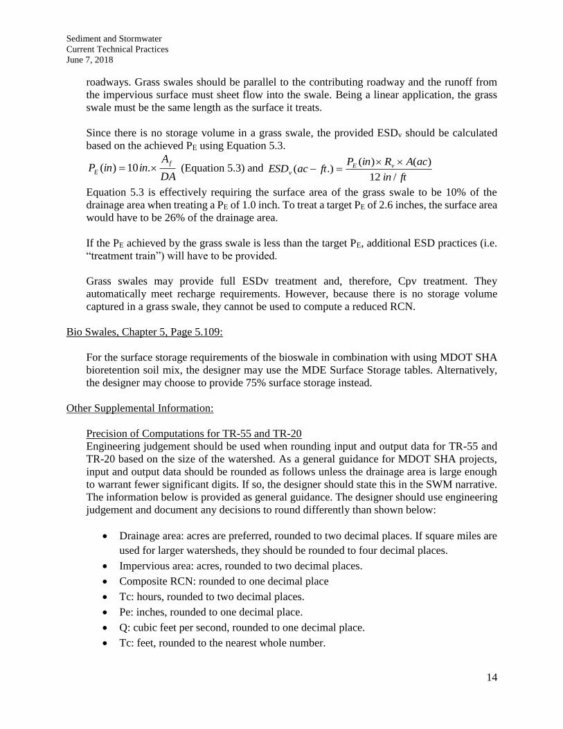
roadways. Grass swales should be parallel to the contributing roadway and the runoff from
the impervious surface must sheet flow into the swale. Being a linear application, the grass
swale must be the same length as the surface it treats.
Since there is no storage volume in a grass swale, the provided ESDv should be calculated
based on the achieved PE using Equation 5.3.
DA
AininP
f
E .10)( (Equation 5.3) and ftin
acARinPftacESD vE
v/12
)()(.)(
Equation 5.3 is effectively requiring the surface area of the grass swale to be 10% of the
drainage area when treating a PE of 1.0 inch. To treat a target PE of 2.6 inches, the surface area
would have to be 26% of the drainage area.
If the PE achieved by the grass swale is less than the target PE, additional ESD practices (i.e.
“treatment train”) will have to be provided.
Grass swales may provide full ESDv treatment and, therefore, Cpv treatment. They
automatically meet recharge requirements. However, because there is no storage volume
captured in a grass swale, they cannot be used to compute a reduced RCN.
Bio Swales, Chapter 5, Page 5.109:
For the surface storage requirements of the bioswale in combination with using MDOT SHA
bioretention soil mix, the designer may use the MDE Surface Storage tables. Alternatively,
the designer may choose to provide 75% surface storage instead.
Other Supplemental Information:
Precision of Computations for TR-55 and TR-20
Engineering judgement should be used when rounding input and output data for TR-55 and
TR-20 based on the size of the watershed. As a general guidance for MDOT SHA projects,
input and output data should be rounded as follows unless the drainage area is large enough
to warrant fewer significant digits. If so, the designer should state this in the SWM narrative.
The information below is provided as general guidance. The designer should use engineering
judgement and document any decisions to round differently than shown below:
• Drainage area: acres are preferred, rounded to two decimal places. If square miles are
used for larger watersheds, they should be rounded to four decimal places.
• Impervious area: acres, rounded to two decimal places.
• Composite RCN: rounded to one decimal place
• Tc: hours, rounded to two decimal places.
• Pe: inches, rounded to one decimal place.
• Q: cubic feet per second, rounded to one decimal place.
• Tc: feet, rounded to the nearest whole number.

Sediment and Stormwater
Current Technical Practices
June 7, 2018
15
• Slope: feet/feet, rounded to two decimal places for ground surfaces and three decimal
places for hard surfaces.
Dividing Drainage Areas
Roadways (and particularly highways) are not hydrologically homogeneous to the rest of the
area draining to the point of investigation, so the roadway should be subdivided as a separate
sub-drainage area. The time of concentration for the sub-drainage area with the roadway will
be much shorter and the RCN will be higher than the adjoining drainage area. When
determining Tc or flow to a BMP, similar considerations may be applicable.
Bridge Deck and Bridge Replacement
Bridge decks are impervious surfaces that collect pollutants regardless of whether they span
pervious areas, pavement, or water. Water quality control must be provided for this surface,
and the area must be included in computations for IART, unless the work meets the criteria to
be classified as maintenance.
Bridge deck replacement is maintenance and qualifies for a 3.3.A waiver. When an existing
bridge is fully or partially reconstructed to the original footprint, elevation, and design without
any widening, the work is also considered to be maintenance and qualifies for a 3.3.A waiver.
In either case, full depth replacement of the roadway approaches is typical for proper transition
of slopes. PRD will consider 50 feet on each side of the bridge of the pavement replacement
to be maintenance.
When a bridge is widened, or the design otherwise altered, an area equal to the original
impervious surface area will be considered reconstruction. Any additional surface area will
be considered new impervious cover and requires both WQv and Cpv. County quantity
management requirements, if applicable, must be addressed. Replacement of bridge
approaches will be considered reconstruction within the existing footprint and new impervious
outside the existing footprint.
When bridge scuppers are relocated, the extent of relocation shall be reviewed in determining
its impact on stormwater management. It is preferred that scuppers not discharge directly into
bodies of water. Water quality opportunities should be sought at the new discharge point.
Water quantity and channel protection needs should be evaluated.
Pedestrian Bridges
Pedestrian bridges that cross existing impervious areas do not need to provide stormwater
management. If a pedestrian bridge crosses new impervious area, either the pedestrian bridge
or the impervious surface area below will have to be treated, dependent upon how the runoff
from the bridge is collected and where it discharges. If the pedestrian bridge crosses pervious
areas and the runoff from the pedestrian bridge reaches the pervious area below in a manner
that disperses the flow (e.g. a wood plank pedestrian bridge where water runs off in the gaps
between planks), then no SWM treatment is required. If that is not the case, then it is like a
sidewalk and SWM is required.
Sediment and Stormwater
Current Technical Practices
June 7, 2018
16
Pervious Pavement
Pervious pavements are designed to allow rainfall to pass through pavement surface to
infiltrate into the soils below that surface. In the SWM calculations, pervious pavements
should be included in the IART calculations, but the surface area of the pervious pavements
should also be included in the IAT. Care must be taken during the plan review and construction
process to ensure that the in-situ soils below proposed pervious pavement areas are not
compacted.
It is typical for drive aisles in permeable pavement parking lots to be constructed of traditional
non-permeable pavement. It is acceptable for these pavement drive aisles to drain to the
pervious pavement if the impervious run-on is limited, and the discharge onto the pervious
pavement is evenly distributed and sheet flow. To consider these impervious pavement areas
as treated, the pervious pavement section must provide storage for the ESDv required to treat
those impervious areas in addition to the ESDv required to treat the pervious pavement itself.
The drainage area to permeable pavements should not include vegetated pervious areas such
as lawn or landscape areas because of the potential for clogging the surface of the pervious
pavement.
Gravel and Ballast
Stone surfaces that are used for vehicular traffic, such as GAB or CR-6, are considered
impervious because vehicles compact the surface over time, causing the surface to have the
same hydrologic characteristics as a paved surface.
Stone used with a cellular confinement system or riprap used for erosion control or infiltration
systems should not compact if it is properly installed. It is therefore considered a pervious or
alternative surface.
Stone that is not used for vehicular traffic purpose is considered pervious. Examples of such
use are: in stormwater management facilities, on pedestrian walkways, or as pads around
electrical utilities and outlet protections.
A 50/50 mixture, by volume, of stone and topsoil, seed, and mulch utilized for shoulder edge
drop off is considered pervious. Use of CR-6 or millings for the shoulder edge drop off is
considered impervious.
Railroad ballast is generally considered to be pervious. Some railroad beds, however, are
constructed atop compacted areas, thereby making the ballast impervious.
Reconstruction
If an impervious area that has existing water quality treatment (from a Chapter 3 or Chapter 5
water quality practice/credit or an acceptable innovative technology) is being reconstructed,
additional water quality treatment is generally not required if it is demonstrated that the
existing treatment has been maintained and is functioning as originally designed. An
exception to this is when reconstruction is considered “new development” due to the existing
I≤40% but the existing WQ treatment is only 50%. In this case, WQv treatment will have to
be provided for 100% of the impervious (i.e. an additional 50%).

Sediment and Stormwater
Current Technical Practices
June 7, 2018
17
Soils Investigation
Refer to MDE Technical Memorandum 7 for required soils investigation information.
Stormwater Management BMP Recharge Volume
When a SWM facility has an underdrain, storage for the recharge volume must be provided
in the facility if there is a recharge requirement. Typically, this is provided below the invert
of the underdrain. When this is not feasible, it may be provided in a separate facility. If the
recharge volume is provided upstream of the WQ or ESD facility, the required quality
treatment volume may be reduced by the provided Rev. If the Rev is provided below the
underdrain, it does not contribute additional volume to the provided WQv or ESDv by the
treatment facility. This is consistent with page 2.5 of the Design Manual which says “Rev and
WQv are inclusive. When treated separately, the Rev may be subtracted from the WQv when
sizing the water quality BMP.”