security through technology - rohde & schwarz€¦ · we want to ensure that the rohde &...
TRANSCRIPT

Test systems for V2X communi-cations check transmitters and receivers
The best even better: TV transmitters now more compact and more efficient
Drone monitoring system to counter the misuse of commer-cial drones
A new body scanner ensures greater airport security without compromising passenger convenience.
Security through technology
Wireless technologies Broadcast and media Radiomonitoring / radiolocation
NEWS 216/16

NEWS
Published by Rohde & Schwarz GmbH&Co. KG Mühldorfstrasse 15 · 81671 Münchenwww.rohde-schwarz.com
Regional contact ❙ Europe, Africa, Middle East | +49 89 4129 12345 [email protected]
❙ North America | 1 888 TEST RSA (1 888 837 87 72) [email protected]
❙ Latin America | +1 410 910 79 88 [email protected]
❙ Asia Pacific | +65 65 13 04 88 [email protected]
❙ China | +86 800 810 8228 | +86 400 650 5896 [email protected]
Emails to the editor: [email protected]
Chief editor: Volker Bach, Rohde & Schwarz Editor and layout: Redaktion Drexl&Knobloch GmbH (German) English translation: Dept. 5MS2 Photos: Rohde & Schwarz Printed in Germany Volume 56 Circulation (German, English, French, Spanish and Japanese) approx. 60 000 approx. three times a year ISSN 0028-9108 Supply free of charge through your nearest Rohde & Schwarz representative Reproduction of extracts permitted if source is stated and copy sent to Rohde & Schwarz München. PD 3606.9656.72
R&S® is a registered trademark of Rohde & Schwarz GmbH&Co. KG. Trade names are trademarks of the owners. CDMA2000® is a registered trademark of the Telecommunica tions Industry Association (TIA-USA). The Bluetooth® word mark and logos are registered trademarks owned by the Bluetooth SIG, Inc. and any use of such marks by Rohde & Schwarz is under license. All other trademarks are the properties of their respective owners.
The NEWS appThe R&S®News app for iPad, Android tablets and Amazon Kindle devices can be downloaded free of charge from the respective pro-vider’s app store. The app’s language can be set internally to English, German, French or Spanish.
Besides the texts in the current print edition, all articles published in the last three years, sorted by topic, are accessible in seconds. The content is enriched by videos. Graphical signs mark which new arti-cles have appeared since the app was last opened, guiding you selec-tively to the innovations.
You can find the app in the respective app stores, under the key words R&S News or Rohde & Schwarz.

When it comes to whether or not something that is technically
feasible should be done, opinions vary. The debate becomes partic-
ularly emotional when individual liberties clash with public security
interests. For instance, is it necessary to have full camera surveil-
lance of certain areas, perhaps even with automatic face recog-
nition, in the slight hope that it might record criminal activity or
contain a picture of a person who is sought? Should we ease
restrictions on the privacy of correspondence and telecommu-
nications (protected in the EU by the European Convention on
Human Rights) so that authorities could then track down crim-
inal activities more easily? When it comes to aviation safety, this
issue is less controversial, as the results of a representative survey
recently conducted by the Federal Association for Information Tech-
nology, Telecommunications and New Media (Bitkom) show. The
vast majority of those surveyed approved the use of state-of-the-
art control technology at airports, which is understandable given
the incidents that have occurred around the world in recent years.
Of course we would like security controls to be as unobtrusive as
possible, preferably not even noticeable. Body scanning technology
has not come quite that far yet, but it’s heading that way. The
R&S®QPS from Rohde & Schwarz marks a milestone in this direction.
Its technology, which is capable of detecting potentially dangerous
objects, has broken new ground. The result is welcome news for
passengers: a slight arm movement from a comfortable position in
an open scanning area and you’re done. People will come to appre-
ciate this convenience at many airports in the future (page 40). In
another area, the need for security is less obvious. Small drones
are currently making headlines as delivery trucks of the future.
However, since anyone can buy and fly one, they increasingly wind
up in places where they are unwanted for reasons of confidentiality
or safety – such as at airports, events and private areas. But there
is a solution. Drone detection systems can alert you to these pests
and even keep them at bay, if necessary. R&S®ARDRONIS from
Rohde & Schwarz is such a system, and US President Obama is not
the only one who has been protected by it (page 58).
Cover feature

4
Wireless technologies General purpose
Test systemsR&S®TS8980 and R&S®TS-ITS100Test systems for V2X communications .......................... 8
R&S®NRPMFirst over-the-air power measurement solution for 5G and wireless gigabit components ...................................... 35
TestersR&S®CMW test platformRF and audio testing of Bluetooth® components with just one T&M instrument................... 14
Signal generation and analysisR&S®SMW200AFirst vector signal generator with 2 GHz bandwidth ....................... 20
Testing WLAN 802.11ad up to 65 GHz ..................................... 23
OscilloscopesR&S®RTOTesting MIPI® interfaces with the R&S®RTO oscilloscope ....................... 26
Network analysisR&S®ZNBT20 network analyzerTrue multiport vector network analysis up to 20 GHz ..................................... 32
Signal generation and analysisR&S®FSWP phase noise analyzer and VCO testerVCO measurement at the push of a button ................................ 36
R&S®FSW signal and spectrum analyzerReal-time spectrum analysis of frequency hoppers and ultrashort interference signals ........................... 38
Dear NEWS Readers,
We want to ensure that the Rohde & Schwarz technology magazine addresses your needs and interests even better in the future and to do so, we need your help.
We would appreciate it if you could take a few minutes to answer a few questions and let us know how you rate NEWs, how you use it and what topics interest you.
You can quickly fill out the short survey here: www.rohde-schwarz.com/news/survey
Youris importantto us!opinion
OverviewNEWS 216/16

Broadcast and mediaFocus Radiomonitoring / radiolocation
Miscellaneous
Body scannersR&S®QPSSecurity through technology, without compromising passenger convenience ...................................... 40
Particle acceleratorsR&S®THx9 / R&S®BBxRF amplifiers for particle accelerators .......................... 48
Transmitter systemsR&S®THU9evo, R&S®TMU9compact and R&S®TLU9 TV transmittersThe best even better .......................... 53
Drone radiolocationR&S®ARDRONIS monitoring systemDrone monitoring system to counter the misuse of commercial drones ........... 58
Masthead ............................................2 NEWS compact................................. 6 Newsgrams ..................................... 66
Particle accelerators
such as the MAX IV
in Lund, Sweden,
use solid-state high-
power amplifiers from
Rohde & Schwarz
(page 48).
The new
R&S®THU9evo,
R&S®TMU9compact
and R&S®TLU9 TV
transmitters are
unique on the world
market (page 53).
R&S®ARDRONIS helps prevent the misuse of
commercial drones (page 58).
© R
oger
Erik
sson
/ E
SS
NEWS 216/16 5

6
R&S®Scope Rider decodes and triggers CAN / LIN signalsThe new R&S®RTH-K3 software option converts the R&S®Scope Rider into the first handheld oscilloscope on the mar-ket that can decode CAN and LIN bus signals. Easy debugging of these buses is therefore possible directly in the field. The R&S®Scope Rider offers the comfort features of a laboratory oscilloscope, in-cluding convenient triggering on sym-bolic data in CAN DBC file format (air-bag status, engine data, etc.). Decoding is possible through both digital and ana-log channels. Thanks to a separate mem-ory for the bus data, the ongoing sig-
nal acquisition is not impaired by decod-ing. The sampling rate for triggering and decoding is a high 1.25 Gsample/s inde-pendently of the timebase setting and therefore ensures secure data acquisition under all operating conditions. In con-nection with the history function, up to 5000 waveforms can be saved and an-alyzed later. In addition to the CAN / LIN option, triggering and decoding options are already available for the I2C, SPI and UART / RS-232 / RS-422 / RS-485 serial bus systems.
First mid-range four-port network analyzer up to 40 GHzMany DUTs in RF engineering, such as mixers, have more than two ports, which means that a network analyzer with a corresponding number of ports is re-quired for an efficient characterization of these DUTs. Until now, only high-end an-alyzers for the microwave range up to 40 GHz, such as the R&S®ZVA, have met this requirement. In many cases, how-ever, their extensive functionality is not necessary at all. For this reason, many users will find the new R&S®ZNB40 four-port analyzer highly interesting. The in-strument features excellent RF perfor-mance data at an attractive price and outperforms top-class instruments in
terms of everyday practicality. It is quiet, easy to transport and has a small foot-print. The large, high-resolution touch-screen ensures non-fatiguing work. Thanks to the bridges used for the di-rectional element (directional couplers are usually deployed in the upper micro-wave range), the lower frequency limit is 100 kHz instead of the otherwise com-mon 10 MHz, which means that low-fre-quency measurements are possible with-out additional T&M equipment. Last but not least, the R&S®ZNB40 has a modern, future-ready computer platform as a pre-requisite for long-term product sustain-ing engineering.
Compact DOCSIS® generator for tests on cable network components The data over cable service interface specification (DOCSIS) has established itself worldwide as the leading broad-cast standard for cable (TV) networks. DOCSIS allows the networks to be used for a large variety of applications, e. g. to create high-performance service pack-ages consisting of TV, telephony and fast Internet in order to challenge the DSL networks of the telecommunica-tions providers. With the latest evolu-tionary stage 3.1 published at the end of 2013, DOCSIS was catapulted into a completely new performance class, with downstream speeds of up to 10 Gbit/s, making it suitable for UHD TV and other data-hungry applications. Dedicated T&M equipment for DOCSIS 3.1 was long scarce, which meant that compo-
nent manufacturers and network opera-tors had to rely on broadcast equipment to generate signals. The R&S®CLGD ca-ble load generator put things right in 2015. This multichannel device for sim-ulating complex DOCSIS scenarios is now complemented by the single-chan-nel R&S®SFD. The R&S®SFD gener-ates a high-quality upstream or down-stream signal in line with DOCSIS 3.1, 3.0 or J.83 / A / B / C in real time. It also handles analog TV signals (PAL, NTSC). Level, frequency, FEC and constellation can be set. The user data is received via the Ethernet interface or generated us-ing an internal ARB. By adding noise, AC hum, tilt and bit errors, the signals can be modeled realistically. The device is operated using a web browser.
DOCSIS® is a trademark of CableLabs.
NEWS compact

Compact IoT test system for carrier acceptance testsHousehold appliances such as the often mentioned refrigerator that automatically ensures that it remains filled will forge ahead in the foreseeable future. They will be connected to the Internet through the home WLAN. This is not possible in the case of mobile devices, machines, sen-sors and equipment distributed over a wide area. Networking such devices re-quires the use of the cellular infrastruc-ture. The applications involved are often low-end with low data rates, but special requirements in terms of power con-sumption and range. Cellular networks must be prepared for the sheer number
of expected IoT radio modules. It is therefore necessary to test the terminal device radio properties. Some network operators, however, place special de-mands on user devices in their network. The new R&S®TS290 test system can be used to test compliance with these de-mands. It offers provider-dependent test cases for RF characteristics, protocol and performance. These test cases can be run automatically, controlled by the R&S®Contest test sequencer. As a result, terminal device manufacturers and sys-tem integrators can economically verify their IoT products.
Managing complex multicamera recordingsThe R&S®VENICE ingest and playout platform acts as a data hub for broad-casters, TV studios and OB van provid-ers. All recordings are collected and / or played out for transmission. The new R&S®VENICE Control ingest software considerably increases workflow effi-ciency. It enables the simultaneous re-cording of up to 16 independent chan-nels in all common formats and resolu-tions. As a result, major events that in-volve the use of a large number of cam-eras can be broadcast with minimal re-sources. The channels can be bundled into groups and controlled jointly or sep-arately. All settings used for a recording can be saved as scenarios – a time-sav-ing feature for the recording of repeti-
tive events, such as regularly produced shows. Automatic file and folder nam-ing is another time saver. The user cre-ates a single set of wildcard parameters such as the date or channel name, which is automatically filled with values during the recording. The client-server architec-ture also contributes to the high flexibility of an R&S®VENICE Control based work-flow. The software can be installed on any number of clients and enables a re-dundant control of all ingest procedures. In case of a client breakdown, another software instance continues control without interruption. R&S®VENICE Con-trol is available for Windows, Mac OS and Linux.
Automatic DUT monitoring during EMC measurementsThe rules for electromagnetic compatibil-ity (EMC) require that electrical products not emit any electromagnetic interfer-ence (EMI) and that they not react to ex-ternal interference (electromagnetic sus-ceptibility, EMS). These reactions can be completely different depending on the product under consideration. Insofar as such problems are indicated optically, e.g. by warning lamps or status display, a solution is now available for automatic detection: the R&S®AdVISE visual moni-toring system. It consists of software, an R&S®AtomixLT video board and one to two video cameras and requires a work-station with NVIDIA GPU. R&S®AdVISE is typically run as an expansion of the
R&S®EMC32 EMC software. It performs a real time analysis of the camera im-ages of the DUT with up to 60 frames/s, for example, with views of the dash-board in the case of automotive mea-surements. For each camera image, the user can define up to 32 fields referred to as regions of interest (ROI), whose be-havior is monitored and linked to event messages. Changes in the brightness, color and color intensity of an ROI are detected, as well as the length of bar di-agrams. Each ROI is individually configu-rable. Even DUTS with complex reaction behavior can be measured automatically. R&S®AdVISE is available in three models from Lite to High Performance.
NEWS 216/16 7

8
Wireless technologies | Test systems

Test systems for V2X communicationsFuture automated vehicles will be wirelessly networked with their environment and will therefore be able to
preventively respond to dangerous situations. To ensure that the safety-related information is received even
under poor transmission conditions, the transmitter and receiver must comply with minimum standards. The
R&S®TS-ITS100 and R&S®TS8980 RF test systems check whether this is the case.
Automated vehicles can safely navi-gate the road only if they have precise knowledge of their environment and the traffic situation. A wide variety of sen-sors and cameras already provide some of this information. New technologies are needed to further reduce the risk of accidents. Critical traffic situations can be detected before they occur thanks to the wireless exchange of informa-tion between vehicles (V2V commu-nications), as well as between vehi-cles and the traffic infrastructure and all road users (V2X communications). If, for example, all vehicles approaching an intersection exchange information about speed and direction, potential col-lisions can be detected, warnings can be issued, and autonomous counter-measures can be initiated early on. For this reason, the exchange of informa-tion between the vehicles must be reli-able even under poor transmission con-ditions and without line of sight.
Distortions compromise safetyWireless links are prone to failure due to physical effects. Fading includes
shadowing and interferences due to scattering, diffraction, refraction and reflection, which cause multi path prop-agation of the signal. This means that multiple versions of the same signal arrive at the receiving antenna at differ-ent times and with different signal lev-els and distortions. This superposition can distort, attenuate or even cancel the signal.
Another complication is that road users are also continuously moving, which results in time-variant fading scenarios. If a receiver cannot handle time- variant fading, then it might not be able to detect and process the signal. This loss cannot be compensated for by strong coding or a special protocol, creating a considerable risk, especially when drivers rely on the warnings by V2X systems.
Test of physical transmissionTo minimize the safety risk arising from poor transmission conditions, the RF transmitters and receivers in the on-board units (OBU) and roadside units
Fig. 1: OSI layer
model.
Layer Name
7 Application
6 Presentation
5 Session
4 Transport
3 Network
2 Data link Logical link control (LLC)
Medium access control (MAC)
1 Physical
(RSU) of the communications sys-tem must exhibit certain characteris-tics. Developers and users integrating V2X components into their systems can use RF tests to verify these character-istics. The two lowest layers of the OSI model (Fig. 1) are relevant to these tests because they are responsible for the physical transmission of the message: ❙ The physical layer handles the physical transport of the data via a transmission medium. In the case of V2X communi-cations, this transport is wireless. This layer uses specific modulation modes, carrier frequencies and bit rates. Often the quality of the transmission channel is also taken into consideration.
❙ The data link layer is divided into an RF section (MAC) and a protocol sec-tion (LLC). The medium access con-trol (MAC) layer controls the access to the transmission medium for multi-ple users. This is relevant to RF mea-surements. The logical link control (LLC) layer handles tasks such as error detection and correction at the proto-col level.
In contrast to RF tests, tests at the pro-tocol level, i. e. from the LLC layer up to the application layer, are not suitable for verifying RF characteristics. These tests check that the bitstream, which is gen-erated in the LLC layer from the received signal, is processed correctly. Therefore, the success of all tests at the protocol level depends essentially on whether the signal can be safely received and converted into a correct bitstream that will not contain more bit errors than the channel decoder can correct.
NEWS 216/16 9

10
The RF module in the OBU (i. e. the MAC layer and the physical layer) must meet certain minimum requirements, e. g. with respect to power and fre-quency accuracy and packet error rate (PER). In addition, the transmitted sig-nal may not interfere with any of the transmission technologies on adjacent frequencies.
How are the requirements for the RF module checked, and how can it be ensured that a transmitted mes-sage / action is actually received? A look at the wireless communications
industry shows that three different types of RF tests are used to validate and cer-tify smartphones: ❙ Regulatory tests check, for example, whether the transmit signal stays within power limits defined for other frequencies. The regulatory author-ity of a country usually specifies these values, and compliance with them is required by law. These types of specifi-cations are now available for V2X units.
❙ Conformity tests ascertain whether a smartphone meets the RF specifica-tions of the respective wireless stan-dard. For example, smartphones must
Fig. 2: The
R&S®TS8980
(left, for LTE) and
R&S®TS-ITS100 (for
WLAN 802.11p)
RF test systems per-
form all required con-
ducted tests in the
development stage.
not exceed a specified maximum packet error rate or maximum transmit power. A separate test specification often describes how to perform and evaluate these tests.
❙ Stricter or additional tests as required by some wireless service provid-ers help them to differentiate them-selves from the competition by pro-viding better transmission quality and higher network reliability. Only mobile devices that meet these specific requirements are approved for the net-work of this provider.
Wireless technologies | Test systems

Radio signals over cableThe automotive industry tests automo-tive components and electronic con-trol units not only in the lab, but also on testing grounds or on roads. For wire-less communications, this is the equiv-alent of field tests, offering a realis-tic environment for RF tests. However, external influences such as the weather may unpredictably change the RF char-acteristics of the radio link. The test setup and test sequence also depend on the vehicles involved and the antenna locations, and often they can only be changed with considerable effort.
This is not practicable for testing in the development stage. That is why con-ducted tests are performed as an alter-native to field tests, where RF test sys-tems such as the R&S®TS-ITS100 or R&S®TS8980 (Fig. 2) simulate the sig-nals in the radio channel and transmit them to the device under test (DUT) via cable. These RF tests can be performed for each prototype and each software or hardware modification. They provide a large number of advantages: ❙ The tests can be performed at any time and at relatively low cost.
❙ The test conditions are clearly defined and can be changed time and again irrespective of outside influences.
❙ Defined test sequences under identical conditions lead to comparable results, making troubleshooting easier.
❙ Unlike field tests, parameters such as the fading profile can be easily mod-ified.
❙ Several tests can be combined into series and automated, e. g. as endur-ance tests to check the reliability of a prototype.
❙ RF tests such as error vector magni-tude (EVM) or RX sensitivity tests only make sense as conducted tests, since uncontrollable noise and interference from external sources falsify the mea-surement results in field tests.
Depending on the selected scenario, channel simulation exactly simulates the physical characteristics of the radio link. The R&S®TS-ITS100 RF test system
Fig. 3: Examples of RF tests for checking
OBU and RSU characteristics.
Transmit characteristics ❙ Frequency accuracy ❙ Modulation accuracy ❙ Out-of-band emissions ❙ Transmission power level ❙ Spectrum emission mask ❙ Spurious emissions
Receive characteristics ❙ Adjacent channel rejection ❙ Nonadjacent channel rejection ❙ Decentralized congestion control ❙ Out-of-band emissions when transmitter is off
❙ Performance with fading (packet error rate)
❙ Sensitivity
can also simulate the special V2X fading profiles in real time.
Field tests are useful nonetheless, espe-cially for antenna measurements, e. g. for determining the antenna pattern or for beamforming tests. Conducted tests therefore cannot completely replace the field tests.
Detecting RF problemsTo be able to compare the test results for the various hardware and soft-ware versions of a V2X unit, all test sequences must be clearly defined. Some countries have therefore laid down test specifications for V2X sys-tems that include test cases in four cat-egories (Fig. 3): ❙ TX in-band: The test cases in this group test the transmitter (TX) charac-teristics, such as maximum and mini-mum transmit power, frequency accu-racy and modulation accuracy.
❙ TX out-of-band: The unwanted trans-mit power outside of the allowed fre-quency band must not disrupt other technologies. TX out-of-band test cases measure this transmit power and compare it against the permissible limit value.
❙ RX in-band: This category tests the receiver (RX), for example by mea-suring the lowest receive power at which the received signal can still be decoded or using performance
measurements with fading. Fig. 4 shows a configured V2X fading pro-file on the R&S®SMW200A vector sig-nal generator.
❙ RX out-of-band: Specialized test cases measure whether an OBU or RSU unintentionally emits power into other frequency bands when the transmitter is switched off.
Various V2X plugtests* have shown that especially the TX out-of-band and fading tests are problematic for many DUTs (Fig. 5). The R&S®TS-ITS100 can detect such RF problems as early as the development phase.
At present, various wireless technol-ogies are under discussion for imple-menting V2X communications, in par-ticular WLAN 802.11p, LTE and 5G, which will be available in a few years. Regardless of which technology is used, Rohde & Schwarz already offers the test solutions needed for V2X mea-surements. LTE-based solutions can be tested using the R&S®TS8980 RF test system family. The test scope is con-tinually being adapted to the evolution of LTE, making it also suitable for V2X measurements.
* Events where products from different manufac-turers are tested for compatibility based on a spe-cific standard
NEWS 216/16 11

Power spectrum
5780
–30
–35
–40
–45
–50
–55
–60
–65
–70
–75
5800 5820 5840 5860
Frequency in MHz
Leve
l in
dBm
5880 5900 5920 5940 5960 5980
12
Fig. 6: R&S®Contest
software for the
R&S®TS-ITS100 and
R&S®TS8980 RF test sys-
tems. The small window
on the right shows some
of the parameter settings
that users can configure
themselves.
Fig. 4: Fading profile for V2X at 5.9 GHz on the R&S®SMW200A vector signal generator.
Fig. 5: TX out-of-band test: The transmit power (blue) of a WLAN 802.11p unit exceeds the permissible limit at
multiple points (red line). The frequency range between 5855 MHz and 5925 MHz is reserved for V2X in Europe
and in the US.
Wireless technologies | Test systems

For WLAN 802.11p, the R&S®TS-ITS100 RF test system contains the complete package of test cases for ❙ Europe at 5.9 GHz (ETSI EN 302 571), ❙ USA at 5.9 GHz (IEEE 802.11-2012) and
❙ Japan at 760 MHz (TELEC T257 and ARIB STD-T109).
For out-of-band tests, the test system permits measurements up to 18 GHz and can use a variety of filters as needed for various regions. The system hardware is already set up to handle diversity and multiple input multiple out-put (MIMO). WLAN 802.11p tests pose a special challenge because there is no defined uniform interface to 802.11p units. In order to configure a unit for
a test case, the test software must address the unit with individual com-mands. For this reason, the test system already contains ready-made plug-ins for many units to make fully automated testing possible.
Both test systems are controlled fully automatically using the R&S®Contest software (Fig. 6). It provides a graphical interface for selecting the RF tests, as well as for compiling the test plans and evaluating the results. This software, which has been widely used in the wire-less communications industry for many years, can also test WLAN 802.11p test cases. The R&S®Contest reports can be used for validation and certification.
SummaryIn order to improve road safety, vehi-cles will be wirelessly connected to each other and to the traffic infrastruc-ture in the future. The safety-related information exchanged must be reliably received under all external conditions. Only RF tests, such as those offered by the R&S®TS-ITS100 test system for 802.11p and the R&S®TS8980 test sys-tem for LTE, can ensure that the OBUs and RSUs meet minimum physical requirements, so that lives can be saved in case of emergency.
Dr. Thomas Brüggen
NEWS 216/16 13

14
Wireless technologies | Testers
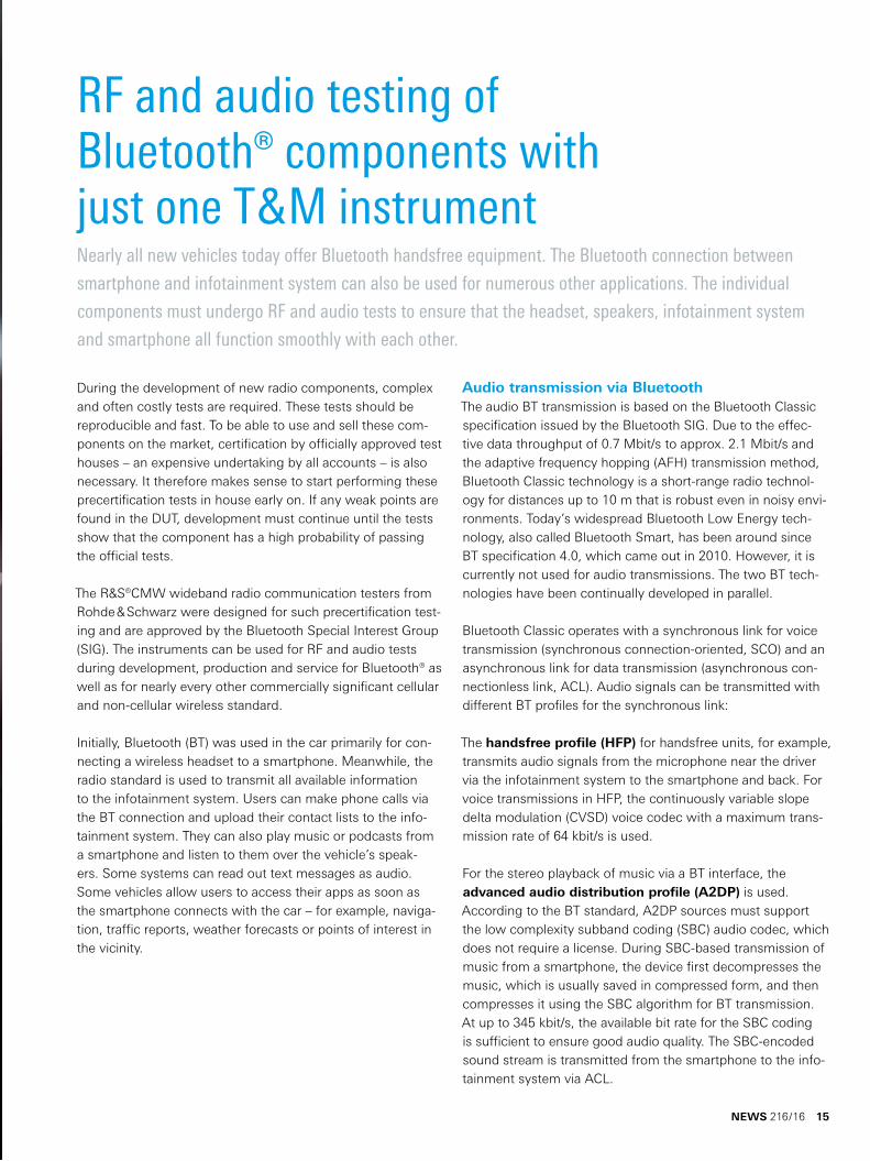
RF and audio testing of Bluetooth® components with just one T&M instrumentNearly all new vehicles today offer Bluetooth handsfree equipment. The Bluetooth connection between
smartphone and infotainment system can also be used for numerous other applications. The individual
components must undergo RF and audio tests to ensure that the headset, speakers, infotainment system
and smartphone all function smoothly with each other.
During the development of new radio components, complex and often costly tests are required. These tests should be reproducible and fast. To be able to use and sell these com-ponents on the market, certification by officially approved test houses – an expensive undertaking by all accounts – is also necessary. It therefore makes sense to start performing these precertification tests in house early on. If any weak points are found in the DUT, development must continue until the tests show that the component has a high probability of passing the official tests.
The R&S®CMW wideband radio communication testers from Rohde & Schwarz were designed for such precertification test-ing and are approved by the Bluetooth Special Interest Group (SIG). The instruments can be used for RF and audio tests during development, production and service for Bluetooth® as well as for nearly every other commercially significant cellular and non-cellular wireless standard.
Initially, Bluetooth (BT) was used in the car primarily for con-necting a wireless headset to a smartphone. Meanwhile, the radio standard is used to transmit all available information to the infotainment system. Users can make phone calls via the BT connection and upload their contact lists to the info-tainment system. They can also play music or podcasts from a smartphone and listen to them over the vehicle’s speak-ers. Some systems can read out text messages as audio. Some vehicles allow users to access their apps as soon as the smartphone connects with the car – for example, naviga-tion, traffic reports, weather forecasts or points of interest in the vicinity.
Audio transmission via BluetoothThe audio BT transmission is based on the Bluetooth Classic specification issued by the Bluetooth SIG. Due to the effec-tive data throughput of 0.7 Mbit/s to approx. 2.1 Mbit/s and the adaptive frequency hopping (AFH) transmission method, Bluetooth Classic technology is a short-range radio technol-ogy for distances up to 10 m that is robust even in noisy envi-ronments. Today’s widespread Bluetooth Low Energy tech-nology, also called Bluetooth Smart, has been around since BT specification 4.0, which came out in 2010. However, it is currently not used for audio transmissions. The two BT tech-nologies have been continually developed in parallel.
Bluetooth Classic operates with a synchronous link for voice transmission (synchronous connection-oriented, SCO) and an asynchronous link for data transmission (asynchronous con-nectionless link, ACL). Audio signals can be transmitted with different BT profiles for the synchronous link:
The handsfree profile (HFP) for handsfree units, for example, transmits audio signals from the microphone near the driver via the infotainment system to the smartphone and back. For voice transmissions in HFP, the continuously variable slope delta modulation (CVSD) voice codec with a maximum trans-mission rate of 64 kbit/s is used.
For the stereo playback of music via a BT interface, the advanced audio distribution profile (A2DP) is used. According to the BT standard, A2DP sources must support the low complexity subband coding (SBC) audio codec, which does not require a license. During SBC-based transmission of music from a smartphone, the device first decompresses the music, which is usually saved in compressed form, and then compresses it using the SBC algorithm for BT transmission. At up to 345 kbit/s, the available bit rate for the SBC coding is sufficient to ensure good audio quality. The SBC-encoded sound stream is transmitted from the smartphone to the info-tainment system via ACL.
NEWS 216/16 15

Microphone test
R&S®CMW500To BT voice codec and digital analyzer
From analog generator
DUT
Bluetooth®
16
Criteria for audio measurementsFor BT transmission of sound information, it is crucial that the tone is reproduced with as high a quality as possible, without noise or dropouts. This is ensured by separately testing all of the components in the transmission chain, i. e. both the radio link as a whole and the individual audio components.
The quality of the audio signal can be determined on the basis of criteria such as frequency response, total harmonic distor-tion and signal-to-noise ratio. Due to the low frequencies in the audio range, the settling times of filters play a role. There-fore, the T&M instrument should be able to adjust to the fre-quency of the test signal so that measurements can be per-formed as quickly as possible. This applies to level measure-ments as well as to complex analyses such as total harmonic distortion plus noise (THD+N).
A BT T&M instrument must be able to establish a complete BT connection to the DUT via the SCO link or ACL link. The tester should also support the relevant codecs and profiles for all audio transmissions. At present, these are the nar-rowband CVSD codec and the wideband mSBC codec with
the handsfree profile and the wideband SBC codec with the A2DP profile. For precise audio analysis, the tester should also be able to send commands to set the level of the micro-phone and speakers. These level settings are specified in the Bluetooth SIG audio video remote control profile (AVRCP). All of these can be verified by using a T&M instrument that has been approved by the Bluetooth SIG.
Relevant audio tests for developersThe R&S®CMW500 uses an integrated two-channel audio generator to check the BT audio quality. It offers various mea-surement procedures: in multitone mode, a developer can define up to 20 sounds for each audio channel (level and fre-quency) and measure the associated frequency responses.
In single-tone mode, the following parameters can be spec-ified for a sine signal: audio level, frequency, signal-to-noise and distortion (SINAD) ratio, total harmonic distortion (THD) and THD plus noise (THD+N). There are also several filters that can be selected for the audio measurement.
Testing the microphone of a Bluetooth headset also involves testing the headset’s audio input amplifier and A/D converter. The BT tester’s audio genera-
tor produces the audio signal, which is transmitted to the microphone under test via a reference speaker. The microphone then transmits this audio sig-
nal via a Bluetooth link to the tester’s audio analyzer, where the signal is measured and compared against the originally transmitted signal.
Wireless technologies | Testers

Speaker and stereo test
From digital generator to BT voice codec
To analog analyzer
Streaming
DUT
Stereo
Bluetooth®
R&S®CMW500
Stereo transmission of musicStereo transmission of music is carried out via the A2DP pro-file with SBC coding and uses the wideband asynchronous link (ACL) for data transmission. BT devices that support A2DP must correctly process signals from SBC codecs. Tests with SBC-coded signals based on ACL also show whether the DUT correctly transmits lengthy packets. It is also practi-cal if the BT tester can analyze and play all of the SBC codec modes such as dual, mono, stereo and joint stereo (dual mode for high-quality transmissions).
Relevant RF tests for developersWhen developing a device with a BT interface, functional tests, interoperability tests and the range are relevant. The receiver sensitivity and transmit characteristics of the components are crucial for the range. In order to measure the transmit char-acteristics of a BT component, the developer must be able to reproducibly determine characteristic values such as power, spectrum, frequency accuracy, frequency drift, frequency deviation and the modulation index calculated from these val-ues. This receiver sensitivity is measured using an artificially impaired signal generated by the BT tester (dirty transmitter).
Testing of headset speakers also involves the D/A converter and the output amplifier in the headset. The BT tester’s audio generator produces an audio
signal and transmits it via a BT link to the headset. There it is amplified and converted to an acoustic signal via a sound converter. This signal is picked
up by a reference microphone and sent via a reference amplifier to the tester’s audio analyzer, where it is displayed and evaluated. Audio tests on the
BT module of an infotainment system are performed in the same way.
Bluetooth module receiver tests are performed by sending, with high accuracy, data from a precise generator to the receiver. The data is analyzed either by having the receiver return the bit sequence or by using an external control PC for analysis.
Numerous other RF signaling tests as well as spectrum mea-surements on newly developed BT components will be required until they receive certification from the Bluetooth SIG. The R&S®CMW testers support these audio tests, plus all 38 currently defined RF signaling tests, with all test cases. For the time-consuming spectrum measurements that are also part of Bluetooth qualification tests, the R&S®CMW provides first test results in less than one second, something no other BT tester on the market can do. The parametric test concept allows users to set all parameters themselves. They now have a compact solution for performing automated prequal-ification tests for Bluetooth Basic Rate, Enhanced Data Rate and Low Energy in line with Bluetooth core specifications 2.0, 2.1+EDR, 3.0+HS, 4.0, 4.1, 4.2 and 5. The easy-to-use R&S®CMWrun sequencer software also helps.
NEWS 216/16 17
18
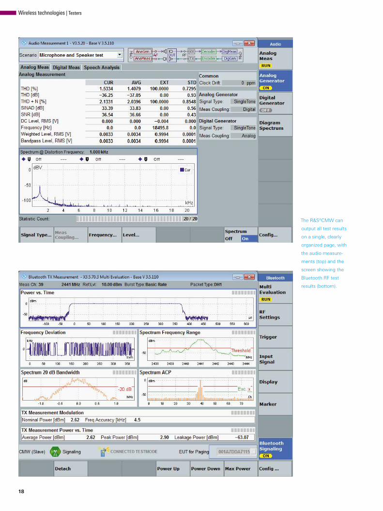
The R&S®CMW can
output all test results
on a single, clearly
organized page, with
the audio measure-
ments (top) and the
screen showing the
Bluetooth RF test
results (bottom).
Wireless technologies | Testers

R&S®CMW500 applications
LTE / LTE-A GSM
RFRF Audio
Classic
WCDMA
WCDMA
Bluetooth®
Low Energy
WLANa/b/g/nac, p
Especially for production use, the R&S®CMW platform offers numerous hardware and software options so that the tester can be customized to the measurement requirements on site. The R&S®CMWrun sequencer software can be used to auto-mate production tests. The software also makes it possible to integrate the tester into a comprehensive test system. The platform offers all essential measurements at an excellent price/performance ratio.
Bluetooth plus other radio technologiesThe user can expand testing with the R&S®CMW to include other radio technologies. Many devices support more than just Bluetooth. They also support WLAN, GPS and various cellular technologies such as LTE, WCDMA and GSM. When WLAN and BT components use the same antenna, the devel-oper can test both radio technologies with one test configura-tion. If the R&S®CMW is equipped with the appropriate hard-ware and software options, it is possible to test all of the inte-grated radio modules in a component up to precertification. This permits the developer to also check whether and to what extent the individual radio modules influence one another (coexistence testing).
SummaryBluetooth has established itself as the short-range radio stan-dard for communications between smartphones and info-tainment systems in automobiles. Error-free functionality of BT components as well as their certification in line with the Bluetooth SIG specifications make standard- compliant RF tests necessary. Reliable audio frequency testing of BT products that use audio profiles is also a sensible idea. Both test tasks can be easily performed using the R&S®CMW family of testers. These are the only testers on the market with the capability of testing all cellular and non-cellular stan-dards using just one instrument and one test setup.
Dieter Mahnken; Ute Philipp
The R&S®CMW test platform
supports a number of different
radio technologies. The modular
approach enables individual con-
figurations for the development,
production and servicing of radio
components.
NEWS 216/16 19
20
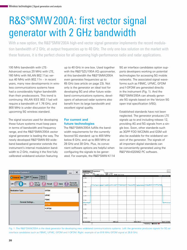
Fig. 1: The R&S®SWM200A is the ideal generator for developing new wideband communications systems. Left: the generator produces signals for 5G air
interface candidates such as FBMC, UFMC, GFDM and f-OFDM. Right: example of an 816 MHz GFDM signal at 26.8 GHz.
R&S®SMW200A: first vector signal generator with 2 GHz bandwidthWith a new option, the R&S®SMW200A high-end vector signal generator implements the record modula-
tion bandwidth of 2 GHz, at output frequencies up to 40 GHz. The only one-box solution on the market with
these features, it is the perfect choice for all upcoming high-performance radio and radar applications.
100 MHz bandwidth with LTE-Advanced versus 20 MHz with LTE, 160 MHz with WLAN 802.11ac ver-sus 40 MHz with 802.11n – in recent years, many new developments in wire-less communications systems have had a considerably higher bandwidth than their predecessors. This trend is continuing: WLAN IEEE 802.11ad will require a bandwidth of 1.76 GHz, and 800 MHz is under discussion for the upcoming 5G wireless standard.
The signal sources used for developing these future systems must keep pace in terms of bandwidth and frequency range, and the R&S®SMW200A vector signal generator is leading the way. The newly developed R&S®SMW-B9 wide-band baseband generator extends the instrument’s internal modulation band-width to 2 GHz, making it the first fully calibrated wideband solution featuring
up to 40 GHz in one box. Used together with the R&S®SZU100A I/Q upconverter, at this bandwidth the R&S®SMW200A even generates frequencies up to 65 GHz (see article on page 23). Not only is the generator an ideal tool for developing 5G and other future wide-band communications systems, devel-opers of advanced radar systems also benefit from its large bandwidth and excellent signal quality.
For current and future technologiesThe R&S®SMW200A fulfills the band-width requirements for the currently favored 5G standard: up to 400 MHz below 6 GHz, and up to 800 MHz at 28 GHz and 39 GHz. Plus, its conve-nient software options are helpful when configuring the signals to be gener-ated. For example, the R&S®SMW-K114
5G air interface candidates option sup-ports developers working on potential technologies for accessing 5G mobile networks. The associated signal wave-forms such as FBMC, UFMC, GFDM and f-OFDM are generated directly in the instrument (Fig. 1). And the R&S®SMW200A can already gener-ate 5G signals based on the Verizon 5G open trial specification (V5G).
Established standards have not been neglected. The generator produces LTE signals up to and including release 12, providing 4G and 5G signals from a sin-gle box. Soon, other standards such as 3GPP FDD WCDMA and GSM will also be available for the wideband ver-sion of the generator. The signals of all important digital standards can be conveniently generated using the R&S®WinIQSIM2 PC software.
Wireless technologies | Signal generation and analysis

Outstanding modulation characteristicsA fully calibrated one-box solution, the R&S®SMW200A generates wideband signals with outstanding modulation characteristics, for example 1.76 GHz WLAN 802.11ad signals (MCS 12 at an IF of 15 GHz) with a measured EVM of –34 dB. Due to the very large band-widths of the new communications standards, frequency response effects are considerably more noticeable than is the case with narrowband systems. In order to minimize unwanted signal distortions, a vector signal generator
must exhibit a modulation frequency response that is as flat as possible (see box). The R&S®SMW200A attains val-ues of < 0.4 dB over the entire band-width of 2 GHz (Fig. 4). To achieve any-where near this kind of performance, existing multibox solutions require addi-tional, time-consuming calibrations.
The core of the new baseband section is the R&S®SMW-B9 baseband generator. It includes an arbitrary waveform gener-ator as well as a coder for real time sig-nal generation and can be configured with different software options to match
Why a flat I/Q modulation frequency response is importantTo generate signal scenarios of several 100 MHz up to 2 GHz, the I/Q modulation frequency response should be as flat as possible. Otherwise signal distortions will occur that could significantly impair the measurements. Some examples: ❙ A flat modulation frequency response leads to a low fre-quency response and better image suppression in the case of multicarrier CW signals, which are often used in component tests (Figs. 2 and 3). With measurements of this type, the signal distortions caused by the DUT are analyzed, which is why the signals provided by the gen-erator should be as ideal as possible.
❙ With wideband, digitally modulated signals as occur in 5G or IEEE 802.11ad, the I/Q modulation frequency response directly influences EVM performance.
❙ Wideband chirp signals are often used in radar tests. A flat modulation frequency response results in better lin-earity.
❙ If modulated multicarrier scenarios with a large overall bandwidth are generated, a large modulation frequency response can considerably distort the relative level ratios of the carriers.
Fig. 2: The R&S®SMW200A generates high-quality wideband sig-
nals, even signals that are asymmetrical to the center frequency.
The diagram shows an asymmetrical multicarrier CW scenario
spanning 2 GHz (the right half of the carriers is switched off).
the specific requirements. The maxi-mum signal bandwidth is 500 MHz in the base version, and 2 GHz in the fully configured instrument. There are also two configurations for the ARB mem-ory depth: 256 Msample and 2 Gsam-ple. Besides the aforementioned digital standards, the new baseband generator can generate user-defined digital mod-ulation signals in real time with symbol rates up to 600 Msymbol/s. It supports many formats, including the higher-order quadrature amplitude modulation (QAM) formats that are often needed for simple receiver tests in satellite systems.
Fig. 3: This is what the scenario shown in Fig. 2 looks like when it is
generated with a conventional generator that does not feature the
excellent modulation frequency response of the R&S®SMW200A.
The frequency response of the generated carriers and the unwanted
images on the right side are clearly seen.
NEWS 216/16 21

I/Q modulation frequency response
5 GHz
15 GHz
18 GHz
28 GHz
35 GHz
–1000 –800 –600 –400 –200 0 200 400 600 800 1000
Frequency offset in MHz
Freq
uenc
y re
spon
se in
dB
0.6
0.4
0.2
0
–0.2
–0.4
–0.6
–0.8
One R&S®SMW200A can replace four instruments
22
Fig. 4: Measured I/Q modulation frequency response with the R&S®SMW-B9 baseband generator option. The R&S®SMW200A attains values of < 0.4 dB
over the entire bandwidth of 2 GHz.
There is room for up to two R&S®SMW-B9 baseband generators in a single instrument, allowing the R&S®SMW200A to generate two inde-pendent wideband signals up to 20 GHz with any desired modulation type. A setup of this kind previously required a vector signal generator and a sep-arate wideband arbitrary waveform generator per signal source, i. e. an R&S®SMW200A replaces four instru-ments (Fig. 5). Now compact test set-ups are possible for sophisticated appli-cations in A&D and wireless communi-cations, for example to simulate com-plex radar scenarios or wanted / interfer-ing signal configurations.
Fig. 5: Equipped with
two built-in base-
band generators, the
R&S®SMW200A can
generate two inde-
pendent wideband
signals up to 20 GHz
with any desired
modulation type. Pre-
viously, this required
four instruments.
SummaryThe new R&S®SMW-B9 wideband baseband generator upgrades the R&S®SMW200A, making it the first vec-tor signal generator to feature an inter-nal modulation bandwidth of 2 GHz in the frequency range up to 40 GHz. It is
ideal for demanding applications that require top-quality, large-bandwidth sig-nals, especially for developing advanced radar systems and new communica-tions standards such as 5G and WLAN IEEE 802.11ad.
Dr. René Desquiotz
Wireless technologies | Signal generation and analysis

Generating wideband signals up to 65 GHz for testing WLAN 802.11ad receivers is a major challenge.
The R&S®SMW200A vector signal generator in combination with the new R&S®SZU100A IQ upconverter
masters this task and allows objective evaluation of the receivers’ performance.
R&S®SMW200A vector signal generator: testing WLAN 802.11ad up to 65 GHz
Modern wireless communications sce-narios require ever higher information data rates up to the Gbit range. Large amounts of data are managed in cloud storage and must be available quickly at any time. Wireless devices are the future: mobile phones that are quickly synchronized with multimedia libraries or laptops that exchange high video data volumes in 4K quality using wire-less docks with external hard disks, servers, TV sets or projectors.
Signal generators for developing such applications must reach beyond con-ventional modulation bandwidths and frequency ranges. Requirement speci-fications include generating wideband signals up to the 60 GHz range as well as an RF bandwidth of 2 GHz – with high output power and excellent sig-nal quality. This article describes how the new R&S®SZU100A IQ upconverter now expands the capabilities of the R&S®SMW200A vector signal genera-tor up to 65 GHz, especially for WLAN 802.11ad applications.
65 GHz – a T&M challenge Up to now, reproducible tests on mil-limeterwave receivers have been very complex. For some time, wideband test signals up to the 40 GHz range have been easily generated directly with vector signal generators such as the R&S®SMW200A. Signals up to the 60 GHz range (e. g. for receiver tests for WLAN 802.11ad) however, required an additional RF mixer in order to achieve the target frequencies from 57.32 GHz to 65.80 GHz. But these conventional
mixer setups have some disadvantages. For example, for practical reasons, upconversion into the 60 GHz band often takes place in several stages. This typically results in local oscillator (LO) mixing products that lie in the operating band. Moreover, additional filters must be used to suppress unwanted side-bands that occur during mixing.
Conventional mixing concepts are also subject to fluctuating RF characteristics. Depending on frequency and level, the setup typically has a different frequency response. To cope with this, the actual frequency response must be recorded and tediously corrected using external measuring equipment. However, this compensation is only valid for one level and one frequency, which in practice requires a recalibration before each measurement, resulting in considerably longer measurement times.
The significantly stronger attenuation of the propagation of millimeterwaves compared to frequencies below 6 GHz complicates matters even more. In a conducted test setup, an attenua-tion of 7 dB to 10 dB per meter can be expected. However, due to the tight integration of the antenna array and RF frontend, WLAN 802.11ad receiv-ers usually do not allow a wired con-nection. Consequently, tests for WLAN 802.11ad are generally only possible via the air interface.
In a typical over-the-air test setup, the generator signal is passed on to a trans-mitting horn antenna (e. g. with 23 dBi gain), and the receiver under test is
placed at a distance of one meter, for example. At 60 GHz the free-field atten-uation is 68 dB/m which means that these tests require a relatively high out-put power of the signal generator. To meet the WLAN 802.11ad receiver sen-sitivity limit of –53 dBm for an MCS 12 signal, the signal generator must pro-duce a signal with at least –8 dBm transmit power. Losses in the test setup caused by switches, adapters or feed cables increase the required power to 0 dBm or more. If a WLAN receiver is to be tested up to its limits, very low levels with the same modulation quality and, in particular, good signal-to-noise ratio must also be generated – a major chal-lenge for conventional test setups.
Vector signal generator for 65 GHzA unique solution for these measure-ments is the new R&S®SZU100A IQ upconverter, which expands the R&S®SMW200A vector signal generator to the range of 57.32 GHz to 65.80 GHz (Figs. 1 and 2). The generator’s wide-band baseband option (R&S®SMW-B9) creates internal WLAN 802.11ad sig-nals with the required symbol rates of 1.76 GHz. All WLAN-specific parame-ters such as modulation, coding, packet size and MAC header can be configured as required. This approx. 2 GHz base-band signal is fed to the R&S®SZU100A via the analog I/Q input, where it is upconverted to the 60 GHz band using an LO signal from the high-perfor-mance RF synthesis module of the R&S®SMW 200A. The IQ upconverter is controlled via USB and integrates
NEWS 216/16 23

Test setup for WLAN 802.11ad measurements
fLO
USB control
Analog I/Q(unsymmetrical or differential)
Waveguide connector with level detector
R&S®SMW200A vector signal generator3 GHz RF, 2 GHz bandwidth
R&S®SZU100A IQ upconverter57.32 to 65.80 GHz
Shielded box with horn antenna
DUT
24
seamlessly into the R&S®SMW 200A operating concept. Frequency and level are adjusted, as usual, via the sig-nal generator’s graphical user interface. Users can easily and conveniently oper-ate the setup as with standalone vector signal generators from Rohde & Schwarz.
High output powerThe R&S®SZU100A is designed as a remote millimeterwave head. It can be placed close to the DUT and flexi-bly positioned with its adjustable feet and variety of mounting points. A horn antenna can be directly mounted to its waveguide output (WR15) with-out requiring an additional adapter. The I/Q upconverter features its own out-put amplifier, an attenuator and, directly on the waveguide output, an integrated level detector. This makes it possible to precisely set levels from –80 dBm to +5 dBm with excellent linearity over the entire dynamic range as well as with vir-tually constant signal-to-noise ratio. Typ-ically, an output level of even more than +10 dBm is available. The sophisticated
synthesis concept ensures that spurs and mirror images are suppressed, eliminating the need for external filters with their undesired insertion losses. All of these measures minimize loss in the test setup and ensure high output power to test the DUT.
Frequency response correction in real timeRohde & Schwarz fully characterizes the IQ upconverter in production and stores the frequency response correction data in its EEPROM. The R&S®SMW200A uses these values during operation to
Fig. 1: The R&S®SZU100A IQ upconverter expands the R&S®SMW 200A to the range of 57.32 GHz
to 65.80 GHz for WLAN 802.11ad receiver measurements.
Wireless technologies | Signal generation and analysis
Frequency response
–1000 –800 –600 –400 –200 0 200 400 600 800 1000
RF frequency response in MHz
Leve
l in
dBm
2.01.51.00.5
0–0.5–1.0–1.5–2.0
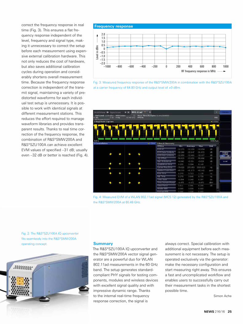
correct the frequency response in real time (Fig. 3). This ensures a flat fre-quency response independent of the level, frequency and signal type, mak-ing it unnecessary to correct the setup before each measurement using expen-sive external calibration hardware. This not only reduces the cost of hardware, but also saves additional calibration cycles during operation and consid-erably shortens overall measurement time. Because the frequency response correction is independent of the trans-mit signal, maintaining a variety of pre-distorted waveforms for each individ-ual test setup is unnecessary. It is pos-sible to work with identical signals at different measurement stations. This reduces the effort required to manage waveform libraries and provides trans-parent results. Thanks to real time cor-rection of the frequency response, the combination of R&S®SMW200A and R&S®SZU100A can achieve excellent EVM values of specified –31 dB; usually even –32 dB or better is reached (Fig. 4).
SummaryThe R&S®SZU100A IQ upconverter and the R&S®SMW200A vector signal gen-erator are a powerful duo for WLAN 802.11ad measurements in the 60 GHz band. The setup generates standard-compliant PHY signals for testing com-ponents, modules and wireless devices with excellent signal quality and with impressive dynamic range. Thanks to the internal real-time frequency response correction, the signal is
Fig. 4: Measured EVM of a WLAN 802.11ad signal (MCS 12) generated by the R&S®SZU100A and
the R&S®SMW200A at 60.48 GHz.
Fig. 3: Measured frequency response of the R&S®SMW200A in combination with the R&S®SZU100A
at a carrier frequency of 64.80 GHz and output level of +0 dBm.
Fig. 2: The R&S®SZU100A IQ upconverter
fits seamlessly into the R&S®SMW200A
operating concept. always correct. Special calibration with additional equipment before each mea-surement is not necessary. The setup is operated exclusively via the generator: make the necessary configuration and start measuring right away. This ensures a fast and uncomplicated workflow and enables users to successfully carry out their measurement tasks in the shortest possible time.
Simon Ache
NEWS 216/16 25

26
Testing MIPI® interfaces with the R&S®RTO oscilloscope Many components in modern smartphones communicate with each other via interfaces standardized by the
MIPI® Alliance. R&S®RTO oscilloscopes can analyze these interfaces’ signal integrity and data content with
maximum efficiency to quickly locate errors.
The MIPI® standards’ ecosystemEach new generation of modern mobile phones enters the market with new features such as additional sensors, higher display resolutions and an extended range of equipment. The numerous components inside these devices communicate quickly and efficiently via common interfaces to offer smooth functionality. The most widely used standards for hardware and software interfaces in mobile phones are from the non-profit MIPI® Alliance, which consists of more than 280 mem-ber companies. According to the MIPI® Alliance, at least one of their standards is implemented in every modern smart-phone and in about 90 % of all classic mobile phones. The MIPI® standards, which are constantly evolving, are also used
in tablets and digital cameras as well as products for the auto-motive and health care sector. Fig. 2 shows the current status.
The standard framework defines three physical layers: D-PHY, C-PHY and M-PHY® (Fig. 3). These physical layers are opti-mized for high-speed (HS) data transmission while maintain-ing low power (LP) consumption. This optimization places special demands on test equipment during development. This article describes the interplay with oscilloscope parame-ters, as well as the variety of debugging capabilities offered by the R&S®RTO oscilloscopes (Fig. 1) for MIPI® protocol implementations.
Fig. 1: The R&S®RTO oscilloscopes’ outstanding RF char-
acteristics and their numerous debugging functions for
MIPI® interfaces save time during development.
General purpose | Oscilloscopes

MIPI® specifications for a mobile device
M-PHY® / D-PHY / C-PHY Chip-to-chip / IPC Multimedia Control and data
M-PHY®D-PHYC-PHY Debug and trace
Power amplifier
Switch
Antenna tuner
Microphone(s)
Speaker(s)
Audio bridge
Audio bridge
Bluetooth®, GNSS,FM radio, NFC
DSI
CSI
UFS
VGI
RFFE
eTrak
SoundWire
SLIMbus®
SoundWire XL
DigRF
Dedicated debug andtrace connector(s)
SD connector
Application processor (host)
Mass storage
Camera(s) /imaging
Audio codec
Sensor hub
Sensors
Companion orbridge chip
Cellularmodem
ETPS
I3C
VGI
LLI/M-PCIeUniPort-M/SSIC
IoT connectivitymodem
Wireless LANmodem
RFICPower management
Battery
SPMI
BIF
USB-C / USB2 / USB3connector
HTI,IEEE 1149.7
MIPI NIDnT: PHY / Pin overlay
SD, HDMI or DP connector
HTI, PTI, IEEE 1149.7
PTI, IEEE 1149.7
HTI
Network connections(TCP, UDP; wired / wireless)
GbD for IP sockets(GbT, SPP)
Functional interface with native protocol
USB-C / USB2 / USB3connector
GdD for USB(GbT, SPP)
Display(s)
MIPI, DigRF, M-PHY, SLIMbus and SoundWire are registered service marks of MIPI® Alliance. Other designations for MIPI® specifications are service marks of MIPI® Alliance. All other trademarks are the property of their respective owners.
The physical layers – specifications and useD-PHY, the most commonly used specification, supports cam-era and display applications. The recently published specifi-cation for C-PHY describes an efficient unidirectional stream-ing interface with low-speed, in-band reverse channel, which should replace D-PHY for higher speed requirements in the future. The third specification, M-PHY®, supports a broader range of applications, including interfaces for display, cam-era, audio, video, memory, power management and interchip
Fig. 2: Overview of the MIPI® specifications’ ecosystem (source: MIPI® Alliance).
communications, for example, between baseband chips and those for RF. In addition, it was adopted as a physical layer for protocols outside of the MIPI® ecosystem such as Mobile PCIe (M-PCIe) and SuperSpeed Inter-Chip (SSIC) USB.
Several higher-level protocols are specified for each phys-ical layer (Fig. 3). Presently, the variants based on C-PHY are barely used. The Unified Protocol (UniPro) specifica-tion makes it possible to use the similarities for higher-layer
NEWS 216/16 27

MIPI® Alliance specifications
Multimedia Chip-to-chip
Protocol layersApplication
Physical layer
DSIdisplayserialinterface
CSI-3camera serial interface
CSI-2camera serial interface
Universalflashstorage(JEDEC)
Seriallow powerinterchipmedia bus
SoundWireSM DigRFSM Superspeedinter chip
(USB)
Mobile PCIe
(PCI / SIG)
Lowlatencyinterface
DisplayDSI
StorageUFS
CameraCSI
D-PHY
C-PHY
M-PHY®
D-PHY
C-PHY
M-PHY®
UniPort-M
UniProSM
UniPort-M
UniProSM
Audio / VoiceSLIMbusSM
RFDigRFSM
Internet-processor communicationsUniPort-M
UniProSM
SoundWireSM LLI SSIC M-PCIe
CMOSI/O
CMOSI/O
M-PHY®
UniPort-M
M-PHY® M-PHY® M-PHY® M-PHY®
Standard D-PHY
HS signaling level (200 mV)
HS common mode level (200 mV)
LP signaling level (1.2 V)
Mass
28
Fig. 3: Applications, protocols and physical layers of the MIPI® standards (source: MIPI® Alliance).
Physical layerTriggering and decoding Compliance tests
CMOS I/O R&S®RTO-K40 ❙ RFFE (V. 1.1)
D-PHY R&S®RTO-K42 ❙ D-PHY (V. 1.2) ❙ CSI-2 (V. 1.2) ❙ DSI (V. 1.3)
R&S®RTO-K26(MIPI CTS for D-PHY V1.1)
M-PHY® R&S®RTO-K44 ❙ M-PHY 4.0 ❙ UniPro 1.6
Fig. 4: Overview of MIPI® standards covered by the R&S®RTO oscillo-
scopes’ analysis options.
protocols based on M-PHY® for interconnecting components within mobile devices. The specification is suitable for a wide range of components including application processors, co-processors and modems, as well as different types of data traffic including control signals, user data transfer and pack-etized streaming.
The R&S®RTO offers different software options for analyz-ing MIPI®-based protocols and their respective physical lay-ers (Fig. 4). The following sections describe how the R&S®RTO effectively handles all T&M requirements of the MIPI® stan-dards. Although both the D-PHY and M-PHY® MIPI® stan-dards serve as examples, the arguments also apply to the other MIPI® options offered by the R&S®RTO.
Fig. 5: Voltage levels of the MIPI® D-PHY signal.
General purpose | Oscilloscopes

Sensitivity versus bandwidth
¸RTO (600 MHz to 4 GHz)
Vertical input sensitivity in mV/div
Band
wid
th in
MHz
4500
4000
3500
3000
2500
2000
1500
1000
500
0
Other oscilloscopes (2.5 GHz, 3.5 GHz, 4 GHz)
54321 1510 20
Detailed analysis of the physical layer increases the tolerance range for the DUTWhen analyzing the physical layer, it is essential to differen-tiate between the DUT’s signal integrity and the signal fidel-ity of the test equipment. Critical oscilloscope parameters include noise, jitter, DC accuracy and bandwidth limitations at high amplification factors. The acquisition of consecutive LP and HS sequences, which have very different signaling levels, is particularly challenging. They require a high signal integ-rity in order to determine signal quality – especially for the HS components. Fig. 5 shows the respective voltage levels.
The better the characteristics of the T&M instrument at hand, the greater the tolerance range for the DUT, resulting in cost savings, lower scrap rates and more efficient measurements. Thanks to its excellent features, this is where the R&S®RTO excels – as shown in the following examples.
Simultaneous acquisition of 200 mV and 1.2 V voltagesWhen characterizing the physical layer, a full scale of 1.4 V is used to acquire the LP signal. 8-bit A/D converters as used in most oscilloscopes provide a full-scale resolution of 5.5 mV/bit. While this is theoretically sufficient for measure-ments on the 200 mV signal (assuming an ideal A/D con-verter), additional influences might render it insufficient. In practice, the A/D converter’s effective number of bits (ENOB) is reduced by several influences such as offset error, gain error, nonlinearity error and static noise. The R&S®RTO oscil-loscopes benefit from their low-noise frontend and pre-cise A/D converters. The converters provide an unmatched dynamic range of > 7 bit (ENOB) that can be fully utilized over the full instrument bandwidth of 4 GHz.
In addition, the R&S®RTO oscilloscope’s low noise reduces the influence of noise floor on the measurement. For exam-ple, actual RMS noise at the selected full scale of 1.4 V (i. e. 140 mV/div), is only about 5.0 mV. This value can be signifi-cantly higher on other oscilloscopes. The high dynamic range of the R&S®RTO and its low inherent noise increase measure-ment accuracy, thereby reducing the rate of rejected DUTs.
Overloading the frontend: a suitable workaround?One workaround to reduce the oscilloscope’s influence on HS signal measurements is to use higher amplification. Using a full scale of 300 mV, for example, increases the resolution to 1.2 mV/bit and reduces RMS noise to 1.1 mV. The disad-vantage to this approach is that the amplifier in front of the A/D converter needs recovery time if operated outside its specified range. During this period, the energy stored in the amplifier causes signal distortions and makes results use-less. Using this approach would only make sense if the signal of interest occurs much later than the transition from the LP to the HS state. The exact time needed for this is usually not
specified by manufacturers but is typically in the range of sev-eral nanoseconds.
Even if an overloaded amplifier does not affect the area of interest, problems may still arise because many oscilloscopes limit the bandwidth for high amplifications in order to reduce noise. These limitations are often drastic and can go down to 500 MHz for the highest amplifications. Since the D-PHY standard requires rise and fall time measurements in the range of 100 ps, oscilloscopes with a bandwidth of at least 3.5 GHz are necessary. With an input sensitivity of 30 mV/div and a typical active probe with an attenuation factor of 10:1, the frontend must be set to 3 mV/div in order to capture the full range of the 200 mV differential signal. The bandwidth of most oscilloscopes is insufficient when set to this value. Thanks to its low-noise frontend and powerful A/D converters, the R&S®RTO oscilloscope’s full instrument bandwidth down to 1 mV/div is available, offering the highest dynamic range for compliance measurements (Fig. 6).
Fig. 6: The R&S®RTO oscilloscope offers full measurement bandwidth at
every input sensitivity, even at 1 mV/div.
NEWS 216/16 29

30
Fig. 7: The main screen of the R&S®ScopeSuite shows the available com-
pliance tests.
In addition to these technical details, an intui-tive workflow quickly leading to results is cru-cial when performing compliance measurements. The R&S®ScopeSuite (Fig. 7) and the respective R&S®RTO-K26 compliance test option offer quick results. Step-by-step instructions and descriptive pictures ensure that measurements succeed on the first try. In addition, the R&S®RTO-K26 compli-ance test option uses the numerous possibilities of the oscilloscope’s digital trigger system’s numer-ous possibilities to quickly isolate the right signals and reduce measurement time.
Analyzing data communications between componentsAfter verifying signal integrity, the next step in design development is to analyze and debug com-munications between different components. Oscil-loscopes with MIPI® triggering and decoding options for serial communications protocols, such as those available for the R&S®RTO (Fig. 4), greatly simplify these measurements.
The R&S®RTO-K44 option, for example, supports debugging directly on the lowest physical M-PHY® layer as well as on the higher UniPro based pro-tocol layers. The 4 GHz R&S®RTO2044 covers UniPro 1.6 up to HS transmission mode gear 2 (HS-G2, 2.9 Gbit/s), making it possible to debug protocols such as CSI-3, UFS and UniPort-M.
To setup the decoding of a two-lane M-PHY® signal, two differential probes (R&S®RT-ZD40) are con-nected to channel 1 and 2. A dialog box guides the user through the configuration (Fig. 8). Users sim-ply need to select either M-PHY® or UniPro and set the number of lanes (up to four lanes are sup-ported). Both coupled and individual threshold val-ues can be used.
The data format and the layer to be decoded is set in a second step. Being able to choose layers is useful for debugging errors on different proto-col levels, starting from the edge transitions, to the bits and symbols, up to the upper UniPro protocol layers (Fig. 9).
In Fig. 10, the setup and activated decoding illus-trate the different bursts for data and markers (MK0, MK1, MK2). The decoding table provides an overview of the bursts. A second table pro-vides details of the data (decode results details 1) for an in-depth analysis of individual bursts.
Fig. 8: Configuration of M-PHY® / UniPro protocol decoding.
Fig. 9: Selection of the decoded layer.
General purpose | Oscilloscopes

Fig. 10: M-PHY® layer
decoding results with
zoom and table dis-
play the details of the
frames and bursts.
Fig. 11: M-PHY® /
UniPro protocol
decoding setup.
Protocol-dependent triggering of the R&S®RTO-K44 option separates the respective data telegrams from one another (Fig. 11). Use of the fast and pre-cise digital triggers, in combination with additional software selection, results in an extremely high-performance workflow.
SummaryThanks to the triggering and decoding as well as compliance test options, the R&S®RTO oscillo-scopes cover all measurements in line with the MIPI® standards. Their outstanding RF characteris-tics and convenient operation enable development engineers to achieve better results in a shorter time.
Dr. Philipp Weigell
NEWS 216/16 31

32
True multiport vector network analysis up to 20 GHzThe new R&S®ZNBT20 multiport network analyzer permits parallel measurements up to 20 GHz on up
to 16 integrated test ports. It offers high speed and accuracy, which provides numerous advantages for
measurements on complex multiport DUTs in development and production.
Fig. 1: With up to 16 test ports and an upper frequency limit of 20 GHz,
the R&S®ZNBT20 supplements the vector network analyzer product range.
The multiport vector network analyzer portfolio has been expanded to meet the growing requirements for multi-port measurements. In addition to the R&S®ZNBT8 (up to 24 ports / 8.5 GHz) and the R&S®ZN-Z84 and R&S®ZN-Z85 switch matrices, the R&S®ZNBT20 vector network analyzer is now available for the frequency range from 100 kHz to 20 GHz (Fig. 1). With eight test ports that can be expanded later to 12 or 16 ports, it can be used universally for applications in devel-opment and production. The many ports are also ideal for sig-nal integrity measurements such as on data cables.
Best multiport performance on the marketIn contrast to solutions based on switch matrix technology, the R&S®ZNBT20 features one measurement receiver and one reference receiver on every test port (Fig. 2). In the parallel mode, it can therefore measure on all ports at the same time, a decisive speed advantage compared with matrix-based mul-tiport solutions (Fig. 3). Even when equipped with 16 ports, the network analyzer offers the excellent performance data of a comparable two-port device at every port because the switches to be provided in switch matrices between the test port and the receivers of the base unit are not required. With up to 130 dB dynamic range between all ports and the out-put level range from –60 dBm to +12 dBm, the R&S®ZNBT20 offers the best multiport performance on the market in the frequency range up to 20 GHz.
General purpose | Network analysis

¸ZNBT20
Meas. receiver
Ref. receiver
Port 16
Reflectometer 16
Meas. receiver
Ref. receiver
Meas. receiver
Ref. receiver
Port 2
Port 1
Reflectometer 2
Reflectometer 1
Generator
Generator
Generator
Generator
24
20
16
12
8
4
Number of sweeps for an N-port measurement5004003002001000
Measurement time comparison
¸ZNBT8 with 24 ports¸ZNBT20 with 16 portsVector network analyzer and 4 × N-port matrixVector network analyzer and 2 × N-port matrix
4412
824
56
1260
132
16
112240
20180
380
24264
552
16
12
8
Num
ber o
f DUT
por
ts
Automated measurements and high throughputAn external monitor and keyboard or an external touchscreen can be connected for operation. Using the intuitive user inter-face already known from the R&S®ZNB vector network ana-lyzer, the R&S®ZNBT20 is easy to configure. Numerous wiz-ards provide support for measuring tasks.
Remote controllability is a key factor for production applica-tions. The R&S®ZNBT20 can be controlled via GPIB, USB or LAN. Using the handler I/O interface, it interacts directly with automated test systems. It controls an external part handler and the test sequence and automatically selects DUTs based on defined criteria.
Automatic calibration units help save time and achieve high measurement accuracy in a cost-efficient manner. They mini-mize the number of required screw connections and the sys-tematic measurement errors since each test port has to be connected to the calibration unit only once. The R&S®ZNBT20 firmware supports all Rohde & Schwarz calibration units and guides the user step by step through the calibration.
Fig. 2: The R&S®ZNBT20 network analyzer’s multiport architecture ensures
excellent RF characteristics.
Fig. 3: Measure-
ment time com-
parison between
R&S®ZNBT8 /
R&S®ZNBT20 and
switch matrix based
multiport solutions.
NEWS 216/16 33

34
Example: time-optimized signal integrity measurements on data cablesData cables generally consist of several twisted wire pairs that have to be tested simultaneously and whose parame-ters, such as crosstalk, skew or rise time, have to be deter-mined. With its multiport architecture and possibility of mea-suring differential systems, the R&S®ZNBT20 is ideal for these tasks. Together with the R&S®ZNBT-K2 and R&S®ZNBT-K20 software options for time domain analysis, such DUTs can be characterized comprehensively. For this purpose, the data measured by the network analyzer in the frequency domain is transformed to the time domain and displayed as an eye dia-gram (Fig. 4). As a result, the transmission characteristics of the DUT can be conveniently analyzed, similar to the method known from time domain measurements. High-performance trace analysis functions complete the functional range. The simultaneous display of frequency and time domain measure-ments and eye diagram prevents complicated switching back and forth between different test setups and delivers all rele-vant analysis parameters at a glance – making configuration quick and easy.
The deembedding / embedding function of the R&S®ZNBT20 also makes it possible to remove the characteristics of test fixtures mathematically from the test setup so that only the characteristics of the DUT are obtained. Extensive network models and touchstone data are available for this purpose. This is vital for measurements of twisted wire pairs since the network analyzer only provides coaxial test ports. These mea-suring options have proven themselves, for example, in the measurement of cables for the USB, HDMI or DVI standards.
SummaryThe R&S®ZNBT20 is a true multiport vector network ana-lyzer up to 20 GHz with up to 16 integrated ports. Due to its sophisticated architecture, it simultaneously measures all test ports, which drastically reduces measurement time com-pared with switch matrix based solutions. Due to its excellent performance data, it can be used for applications in develop-ment and production. The large number of ports is advanta-geous for signal integrity measurements on cables since sev-eral wires can be measured at the same time. Eye diagrams are also available for the comprehensive analysis of DUTs in addition to time domain display.
Anja Paula
Fig. 4: Eye diagrams
as well as frequency
domain and time
domain measure-
ments are displayed
simultaneously.
General purpose | Network analysis

In brief
First over-the-air power measurement solution for 5G and wireless gigabit componentsThe R&S®NRPM is a new solution for direction-dependent measurements of the power of radio signals
directly on the antenna. It enables users in development and production to calibrate the output power of
a DUT in the high microwave range and to test the DUT’s beamforming function.
Next generation mobile communications and WLAN base stations, access points, wireless devices and radio modules will use phased array antennas. Beamforming is used to con-trol the direction of radiation of the trans-mit antenna in order to maximize the power level at the receiver. Due to their high inte-gration, these antennas cannot be connected directly via cables. Therefore, measurements are performed using over-the-air (OTA) inter-faces. The R&S®NRPM sensor system was developed for these measurements. It works in the frequency range from 27.5 GHz to 75 GHz, covering the 28 GHz band currently being discussed for 5G as well as the 55 GHz to 66 GHz band used by IEEE 802.11ad and IEEE 802.11ay gigabit WLAN systems.
The extremely low power levels to below –70 dBm that are to be measured do not allow the power sensor to be connected to the antenna via cable, since the line losses would be too high. The R&S®NRPM sys-
tem is therefore distributed in two parts: the RF frontend, or diode detector, is integrated directly into the antenna module, while the signal processing electronics is accommo-dated in a separate module that has the form of a conventional power sensor. The sensor module has three channels for connecting up to three single-polarized Vivaldi anten-nas (dual-polarized antennas are in prepa-ration). In addition to avoiding power loss, the integration of the diode detector in the antenna also has the advantage that the fre-quency response of the antenna module with the diode detector can be calibrated in the plant. This increases precision and simplifies the measurement procedure so that the user does not need to worry about this aspect.
With a single antenna module, the user can calibrate a DUT’s output power, for example. Multiple, spatially distributed antenna mod-ules make it possible to test a DUT’s beam-forming function. If more than three anten-
nas are needed for a test setup, users can operate any number of sensor modules in parallel. The additional measurement points thus obtained increase the resolution during beamforming tests and allow the setup of 2D matrices for swiveling the antenna beam about two axes.
The free R&S®Power Viewer Plus PC software is available for evaluating and processing measured data. At present, the software can be used to monitor and display measured data from up to twelve channels and to determine the average power, for example.
Users who wish to acquire signals in a shielded test environment in order to obtain reproducible results can use the R&S®TS7124 19" shielded RF test box. For this solution, a shielded and filtered cable feedthrough is available as well as a dielec-trically neutral plastic structure for flexible mounting of the antennas.
The R&S®NRPM consists of at least one antenna
with an integrated diode detector, plus a spa-
tially offset electronics module (sensor mod-
ule). Measurement accessories for operation in
a shielded chamber are also available.
NEWS 216/16 35

36
VCO measurement at the push of a buttonVoltage-controlled oscillators (VCO) can be found in almost all RF applications, and their technical param-
eters significantly influence the quality of the components in which they are used. The R&S®FSWP phase
noise analyzer and VCO tester can comprehensively test VCOs at the push of a button.
The core components in almost all RF applications are volt-age-controlled oscillators (VCO), as in mobile communica-tions, for example. These oscillators change their oscillating frequency as the applied voltage changes. The available volt-age range must be sufficient for a VCO to cover the target fre-quency band. The important quality characteristics of a VCO that need to be measured are its spectral quality, the fre-quency range that it covers, the output power and the current consumption (particularly for mobile applications) and also the tuning slope, which is responsible for smooth settling.
All of these VCO measurements can now be performed by a single measuring instrument at the push of a button: the R&S®FSWP phase noise analyzer and VCO tester (Fig. 1). With
firmware release 1.30, the R&S®FSWP can measure VCOs without the need for an additional option. The user simply adjusts the supply voltage, the tuning voltage range and the number of measuring points. The R&S®FSWP then quickly determines all of the required characteristics. It only needs a few milliseconds for each measuring point. Consequently, the total measuring time primarily depends on the settling time of the VCO. Settling times can also be specified, so that the R&S®FSWP waits accordingly before it starts to measure.
A typical measurement can be seen in Fig. 2, in which all characteristics are shown in parallel. The markers can be coupled via different windows in order to collect all of the important parameters for a certain tuning voltage in a table.
Fig. 1: The R&S®FSWP delivers VCO and phase noise measurements at a
glance: the top pane displays the VCO characteristics, the bottom pane
shows the phase noise measurement at 2 GHz.
General purpose | Signal generation and analysis

External voltage sources are not required. The R&S®FSWP has low-noise sources on board (Fig. 3). The tuning voltage can vary from –10 V to 28 V, with a maximum noise voltage of 1 nV/√Hz (at 10 kHz). An operating voltage source of 16 V – more than sufficient for any oscillator on the market – with a maximum current consumption of 2000 mA is also available. It can also be operated as a current source. The third volt-age source in the R&S®FSWP is useful for measurements on VCOs that require an additional (even negative) voltage. The R&S®FSWP can also tune the operating voltage. This is use-ful for checking the behavior of a transmitter with a weaken-ing battery.
Phase noise is also important for a transmitter’s transmission quality and adjacent channel power, and must be measured. Here the R&S®FSWP excels as the fastest and most sensitive phase noise tester on the market today (see NEWS 214, page 37). For such measurements, the multichannel concept of the R&S®FSWP makes it possible to simultaneously display the phase noise at a certain operating voltage together with the VCO’s characteristics (Fig. 1). A screenshot therefore fully documents all of the main parameters.
Fig. 2: A typical VCO measurement. Key parameters such as frequency, power, sensitivity (tuning slope) and current consumption are measured relative
to the tuning voltage.
Fig. 3: Setting menu for the internal R&S®FSWP voltage sources.
SummaryWith the new capability to comprehensively characterize VCOs at the push of a button, the R&S®FSWP phase noise analyzer and VCO tester more than lives up to its name. Exter-nal voltage sources are not needed for the measurements since the tester comes with internal low-noise sources.
Dr. Wolfgang Wendler
NEWS 216/16 37

38
Real-time spectrum analysis of frequency hoppers and ultrashort interference signalsWith a new option, the R&S®FSW signal and spectrum analyzer characterizes frequency agile systems at
a real-time bandwidth of 512 MHz and reliably detects even extremely short interference signals.
Cordless communications systems such as headsets or handsfree equipment in vehicles often use frequency hopping in order to be less susceptible to interference signals or other applications in the same frequency range. In tactical commu-nications systems and in radar applications, frequency hop-ping is used to increase protection against eavesdropping and to minimize the influence of wanted interferences. To analyze frequency agile systems of this type, the signals must be dis-played accurately, quickly and seamlessly in real time. This is the only way to analyze short unwanted signals in detail.
Up to now, the R&S®FSW signal and spectrum analyzer was equipped with the R&S®FSW-B160R option for these tasks. The new R&S®FSW-B512R option makes it possible to mea-sure at a real-time bandwidth of 512 MHz and to calculate up to 1.1 million spectra per second. It covers the real-time bandwidth more than three times and doubles measurement speed (Fig. 1). With a probability of intercept (POI) of 100 %, the analyzer accurately detects signals with a duration of only 0.91 µs and even captures those with a duration of only a few nanoseconds – although with reduced level accuracy. Because the human eye can only process approx. 30 images per second, the options offer different display modes and features to investigate the events in the frequency and time domain in detail and provide access to the information con-tained in the many spectra. With a conventional real-time dis-play, a detector analyzes many thousands of traces to form a spectrum of maximum values. The display shows if a sig-nal or interferer is present, even if the event lasted only a few
nanoseconds. Thanks to the spectrogram display that pres-ents all spectra with color-coded signal levels in horizontal lines, users are able to resolve the behavior in the frequency domain over time. Frequency hoppers are shown without any interruptions. Fig. 2 shows hop sequences of a Bluetooth® transmitter as well as a WLAN signal that is also found in the ISM band (bottom right). The minimum time resolution is 55 µs. If the user stops continuous recording, a time reso-lution of 20 ns can be achieved via the zoom function during postprocessing of the spectral display. This makes it possible to easily resolve the preamble as well as modulation details of WLAN signals (Fig. 3).
In the persistence spectrum, the analyzer writes all available traces on top of each other and color-codes them according to their probability of occurrence: frequently occurring signals in red, and sporadic ones in blue, for example. If a signal no longer occurs, it disappears from the persistence spectrum after a certain time (Fig. 2, top). The persistence spectrum provides an overview of the dynamic range of frequency agile systems. Frequency hops, such as those occurring in the ISM band where Bluetooth® and WLAN signals collide, reducing data rates, can be accurately analyzed and better frequency hopping algorithms can be found. The analyzer also helps detect extremely short interferers or hidden signals that are hardly detected by conventional spectrum analyzers.
Frequency mask trigger (FMT)The frequency mask trigger should be used if only one spe-cific signal, perhaps one that has been discovered in the spectrogram or the persistence display, or whose frequency is known, is of interest. The user defines a mask in the fre-quency domain and the analyzer compares this mask with up to 1.1 million spectra per second. If a signal violates the mask, the analyzer stops real-time analysis and records it. The time before (pre-trigger) and after (post-trigger) the signal to be recorded can be set. The user can also select whether the analysis should automatically continue after recording. Con-tinuing the analysis provides an overview of how often certain signals occur and whether they behave similarly each time.
Key parameters in real-time analysis
R&S®FSW-B512R R&S®FSW-B160R
FFT length 1024 to 32k 1024 to 16k
Maximum real-time analysis bandwidth 512 MHz 160 MHz
Maximum FFT rate 1,171,875 585,938
POI 0.91 µs 1.87 µs
User-configurable resolution bandwidth (RBW) for span/RBW ratio
6.25 to 6400 6.35 to 3200
Fig. 1: Comparison of the real-time analysis options for the R&S®FSW
signal and spectrum analyzer.
General purpose | Signal generation and analysis

ISM band at 2.4 GHz
Bluetooth® signals
WLAN signal
3G signals at 2.1 GHz
Thanks to multistandard real-time (MSRT) analysis, the recorded data can also be used for other applications such as analog modulation analysis or vector signal anal-ysis (R&S®FSW-K7 / R&S®FSW-K70 options), in order to find out for example, how interference affects the modula-tion characteristics of a wanted signal. The R&S®FSW-K6 option is used for extensive analysis of pulsed signals and the R&S®FSW-K60 / -K60H options are used for automatic analy-sis of hop sequences.
SummaryWith the new option, the R&S®FSW high-end signal and spec-trum analyzer characterizes frequency agile systems at a large real-time bandwidth. This makes it possible to detect extremely short interferers – a valuable additional feature for developers of radar or communications applications, who can also use the instrument to accurately measure all RF parame-ters of an application.
Dr. Wolfgang Wendler
Fig. 2: 3G signals
at 2.1 GHz and
Bluetooth® / WLAN
signals in the ISM
band can be simulta-
neously analyzed with
the R&S®FSW-B512R
option (top: persis-
tence spectrum, bot-
tom: spectrogram).
Fig. 3: The time res-
olution in postpro-
cessing can be sig-
nificantly increased
via the zoom function.
This makes it possible
to quickly analyze fre-
quency hopping sys-
tems or detect modu-
lation details.
NEWS 216/16 39

40
Focus | Body scanners

Security through technologyHow can air traffic security be improved without bothering passengers with yet
more checks? An innovative body scanner shows the way.
The typical air traveler has conflicting feelings about security. According to a representative survey by the German Federal Association for Information Technology, Telecommunications and New Media (Bitkom), most passengers favor the exten-sive use of security technology, including body scanners, at airports. At the same time, they are annoyed about a variety of inconveniences, ranging from the restrictions on carry-on luggage and having to take off various items of clothing at the security checks, to the unnatural posture required by conven-tional body scanners and the pat-downs by security officers. And these are only compounded by the long waits at secu-rity checkpoints. Because it is unlikely that security standards will be relaxed any time soon, it is up to technology to find answers to this dilemma in the face of even tighter security.
The goal is to maintain the highest level of security while pre-serving the greatest degree of convenience possible for pas-sengers. The new R&S®QPS body scanner (Fig. 1) is a signifi-cant step in this direction.
A product category takes shapeThe first body scanners were developed in the early 1990s, even before an appreciable market for them existed. These backscatter devices operating in the X-ray range were sel-dom used at airports. These were followed several years later by devices operating in the microwave range, even though demand remained limited. After the dramatic events of 9/11, it became clear that the market for security equipment would
Fig. 1: The R&S®QPS200 scanner with two panels is primarily intended for use at airports. It can be integrated without barriers into virtually any gate
architecture. The R&S®QPS100 model (not shown) has only one panel; the test person turns 180° for a complete scan.
NEWS 216/16 41
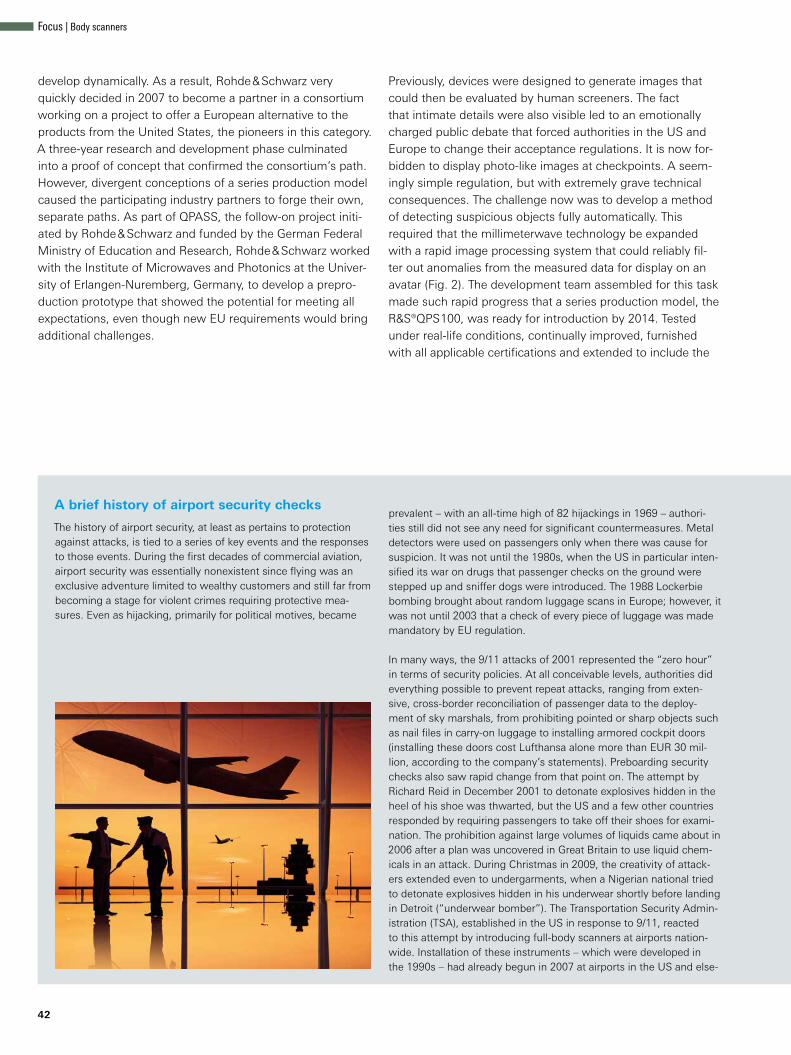
42
develop dynamically. As a result, Rohde & Schwarz very quickly decided in 2007 to become a partner in a consortium working on a project to offer a European alternative to the products from the United States, the pioneers in this category. A three-year research and development phase culminated into a proof of concept that confirmed the consortium’s path. However, divergent conceptions of a series production model caused the participating industry partners to forge their own, separate paths. As part of QPASS, the follow-on project initi-ated by Rohde & Schwarz and funded by the German Federal Ministry of Education and Research, Rohde & Schwarz worked with the Institute of Microwaves and Photonics at the Univer-sity of Erlangen-Nuremberg, Germany, to develop a prepro-duction prototype that showed the potential for meeting all expectations, even though new EU requirements would bring additional challenges.
Previously, devices were designed to generate images that could then be evaluated by human screeners. The fact that intimate details were also visible led to an emotionally charged public debate that forced authorities in the US and Europe to change their acceptance regulations. It is now for-bidden to display photo-like images at checkpoints. A seem-ingly simple regulation, but with extremely grave technical consequences. The challenge now was to develop a method of detecting suspicious objects fully automatically. This required that the millimeterwave technology be expanded with a rapid image processing system that could reliably fil-ter out anomalies from the measured data for display on an avatar (Fig. 2). The development team assembled for this task made such rapid progress that a series production model, the R&S®QPS100, was ready for introduction by 2014. Tested under real-life conditions, continually improved, furnished with all applicable certifications and extended to include the
The history of airport security, at least as pertains to protection against attacks, is tied to a series of key events and the responses to those events. During the first decades of commercial aviation, airport security was essentially nonexistent since flying was an exclusive adventure limited to wealthy customers and still far from becoming a stage for violent crimes requiring protective mea-sures. Even as hijacking, primarily for political motives, became
prevalent – with an all-time high of 82 hijackings in 1969 – authori-ties still did not see any need for significant countermeasures. Metal detectors were used on passengers only when there was cause for suspicion. It was not until the 1980s, when the US in particular inten-sified its war on drugs that passenger checks on the ground were stepped up and sniffer dogs were introduced. The 1988 Lockerbie bombing brought about random luggage scans in Europe; however, it was not until 2003 that a check of every piece of luggage was made mandatory by EU regulation.
In many ways, the 9/11 attacks of 2001 represented the “zero hour” in terms of security policies. At all conceivable levels, authorities did everything possible to prevent repeat attacks, ranging from exten-sive, cross-border reconciliation of passenger data to the deploy-ment of sky marshals, from prohibiting pointed or sharp objects such as nail files in carry-on luggage to installing armored cockpit doors (installing these doors cost Lufthansa alone more than EUR 30 mil-lion, according to the company’s statements). Preboarding security checks also saw rapid change from that point on. The attempt by Richard Reid in December 2001 to detonate explosives hidden in the heel of his shoe was thwarted, but the US and a few other countries responded by requiring passengers to take off their shoes for exami-nation. The prohibition against large volumes of liquids came about in 2006 after a plan was uncovered in Great Britain to use liquid chem-icals in an attack. During Christmas in 2009, the creativity of attack-ers extended even to undergarments, when a Nigerian national tried to detonate explosives hidden in his underwear shortly before landing in Detroit (“underwear bomber”). The Transportation Security Admin-istration (TSA), established in the US in response to 9/11, reacted to this attempt by introducing full-body scanners at airports nation-wide. Installation of these instruments – which were developed in the 1990s – had already begun in 2007 at airports in the US and else-
A brief history of airport security checks
Focus | Body scanners

Fig. 2: The scan result is displayed on a neu-
tral graphic (avatar). No personal details are dis-
played and no personal data is stored.
where, such as Amsterdam, but their widespread use did not start until 2010. This first generation of scanners was based on X-ray tech-nology that made not only potentially dangerous objects visible, but also intimate body details, leading to heavy public criticism. X-rays additionally have an ionizing effect and are therefore damaging to cells, even though authorities ruled out any jeopardy to health due to the low level of radiation from the devices (measurements show that the level is approximately equivalent to what passengers are exposed to during just a few minutes of cosmic radiation). Nevertheless, these backscatter devices have largely disappeared from the market and are now banned in many countries. Even the TSA made an about-face when it removed all first generation devices between the fall of 2012 and May 2013, replacing them with the alternative technology of millimeterwave devices. However, that move was not made out of concerns for public health, but rather because the device manufac-turer had not been able to implement a software update on sched-ule that would depersonalize scan results. In response to the public outcry, US authorities had included a clause in the FAA Moderniza-tion and Reform Act of 2012 to the effect that the naked images gen-erated by body scanners should be replaced with a symbolic body graphic identical for all test persons.
Out of health concerns, the European Union banned X-ray scanners (and all technologies using ionizing radiation) in a regulation issued in November 2011. The preservation of personal and data protec-tion rights is also mandatory. Germany conducted its first field trial of a first generation millimeterwave scanner in 2010 at the Hamburg airport. The field tests were carried out and scientifically assisted by the research center of the German Federal Police. 800,000 volun-teers, including German Federal Minister of the Interior de Maizière, allowed themselves to be scanned. The objectives of the large-scale trial were to determine how the devices would hold up under real-life
conditions, to uncover any trouble spots, and to find out how to optimally implement common test methods. National authorities work directly with the European Civil Aviation Conference (ECAC), which is responsible for certifications related to air transporta-tion, and the Hamburg trial played a pioneering role here. The test results (which included a high percentage of false alarms) led the German Federal Government to conclude that the devices cur-rently available on the market were not yet suited for general use. Manufacturers have since stepped up efforts to improve reliability.
Latest generation scanners, such as the R&S®QPS from Rohde & Schwarz, are considerably more mature than their prede-cessors and are suitable for unrestricted, widespread use. Regu-latory agencies are also demanding that the scanners speed up security checks rather than slowing them down. The fast devices now available make this possible. The increased use of automated security equipment brings justifiable hope that the perceived bur-den on passengers will be reduced to a bearable extent in the foreseeable future. A first step in this direction was the EU-wide elimination of the ban on large volumes of liquids in carry-on lug-gage in 2014 (although limited to medications, special foods, and products obtained from the airport duty-free zone). This was made possible by new technology capable of detecting liquid explo-sives. Advances in scan technology will soon make it possible to screen through thick layers of clothing, so that passengers will no longer be required to take off their coats and jackets. Solutions are already visible on the horizon that will work behind the scenes, i. e. passengers will be subjected to security checks without even noticing it. The hope is that air travelers will be able to board with-out challenge, unlike the woman who had her Christmas cake confiscated in Las Vegas because the security guard thought the icing looked a little too much like explosives.
NEWS 216/16 43

44
R&S®QPS200 model, the R&S®QPS platform today serves as an innovative security solution not only for airports, but for all environments requiring high-security, restricted access. The demand is high. Countries like Germany are following the example of the US, which began in 2010 to successively out-fit all airports with scanners. With the July 2016 signing of a framework agreement between the German Federal Min-istry of the Interior and Rohde & Schwarz for the delivery of 300 units, the R&S®QPS200 is on its way to becoming a familiar sight at German airports.
New pathsThe R&S®QPS differs from competitive products in how it looks, how it operates and how scans are performed. The tight spaces common with booth solutions are a thing of the past. The visually appealing, space-saving flat panels can be integrated without barriers into the checkpoint area (Fig. 1). The open design gives security personnel an unob-structed view of the entire checkpoint. The scan procedure
– considered to be unpleasant with traditional equipment because passengers are required to hold their hands up in the air as if being stopped by police – is now significantly more comfortable for passengers. Arms are slightly spread in a nat-ural pose that is possible even for physically impaired individ-uals and is considered to be ethically correct across cultures.
The R&S®QPS is a fully electronic, low-noise solution with no moving parts. It is the only device on the market that relies on the multistatic principle familiar from radar technology, where the reflected transmit signal is applied to a large number of receive antennas simultaneously (Fig. 3). This provides better illumination of the scanned individual, leading to an improved quality of detection.
Aside from a six-monthly calibration check, the system is vir-tually maintenance-free. These checks are provided on site, of course. Setup and commissioning take under an hour because all time-intensive preliminary work is performed at the plant.
Fig. 3: Multistatic
principle of operation:
While only one of the
3008 transmitters is
active at a time in a
panel, all 3008 receiv-
ing antennas receive
the reflected signal.
Since every transmit-
ter also rapidly steps
through 128 frequen-
cies before the next
one starts transmit-
ting, each scan cycle
delivers more than a
billion (!) complex val-
ues per panel (mag-
nitude and phase), all
within only 32 ms.
Focus | Body scanners

Structure of an R&S®QPS panel
Cluster with transmit (vertical) and receive (horizontal) rows of 47 antennas each
IF module
Centralized board
Central processor (IPC)
PC adapter
Cluster
Fig. 4: The R&S®QPS has a modular design. The RF frontend is distributed
into 32 clusters in a checkerboard pattern.
The technology behind the R&S®QPSTraditional microwave scanners illuminate objects at frequen-cies below 30 GHz. In contrast, the R&S®QPS achieves higher spatial resolution as it operates in the millimeterwave fre-quency band between 70 GHz and 80 GHz, the band also used by vehicle parking sensors. At about 1 mW, the peak transmit power is approximately three orders of magnitude lower than that of cellphone emissions and is almost unde-tectable in the spot where the scanned person stands.
The scan volume is resolved in finely granulated, 1.9 mm × 1.9 mm × 5.7 mm voxels, which is achieved not only due to the high frequency band, but also through the multi-static operating principle. Implementing this in a high-resolu-tion, close-range scanner was anything but a trivial task. To make a multistatic millimeterwave scanner workable, its sur-face would have to be fully covered with antennas – which translates into a quarter million antennas per panel for a scan-ner the size of the R&S®QPS. The effort to reduce the num-ber of antennas to a reasonable level took years of fundamen-tal research and was the basis for more than one doctoral the-sis. The result was a structure consisting of 3008 transmitters and 3008 receivers distributed in 32 clusters over each panel in a checkerboard pattern (Fig. 4). In addition to transmitters and receivers, the clusters contain the electronics required for frequency processing and conversion. The receive signals are downconverted to a 25 MHz IF, and the signals from four clusters each are taken to one of a total of eight IF modules located behind them. In the IF modules, they undergo analog-to-digital conversion and are processed into raw “image” data. In a final step, the data is routed via two centralized boards and a PC adapter to an integrated interprocess communi-cations (IPC) module, where final data analysis takes place. Potentially dangerous objects are automatically detected, and their precise location is calculated and displayed. Each panel also houses a synthesis generator for signal generation as well as auxiliary components such as the power supply, signal distribution, interface ports and display elements.
The R&S®QPS200 is designed to perform a full scan in just 32 ms per panel. Computer analysis at present takes several seconds, a time that will be significantly reduced in the future through more powerful data processing technologies. High-performance graphics processing units (GPU) optimized by the graphics cards industry for massively parallel processing introduce new options on the way toward implementing real-time analysis, an essential prerequisite also for future walk-through solutions.
The challenge of automated detectionOn the surface, a body scanner works much the same as a classic passport photo booth. The person is illuminated, the reflected light is replicated onto a medium (in the case of the scanner to data instead of paper), and the image is devel-oped – by means of scanner software. However, a fully auto-matic scanner is not intended to generate photographs for human viewing. Instead, its purpose is to deliver an image interpretation, an assessment – which is a significantly more demanding task.
The task is as simple and challenging as this: detect all poten-tially dangerous objects that are carried on the body or in clothing, regardless of type, size, location and material com-position.1) The all-encompassing scope of this task quickly leads to the conclusion that obtaining a positive validation, i.e. detecting concrete objects by way of comparison against patterns, is predestined to failure. There are simply too many materials and shapes that can be used for firearms or knives, for example. A scanner would have to be capable of recog-nizing a “thing in itself”, based on its characteristics and pur-pose, irrespective of shape, material or form – a hopeless endeavor. The goal of the scan, therefore, is not to identify objects but to identify areas on the body that, in the estima-tion of the analysis software, significantly deviate from the
NEWS 216/16 45

Mapping of measured data to object characteristics by means of classifiers
Attribute 1: double reflection
Attribute 2: local mean value
Attribute m: amplitude distribution
•••
Classifier 1 Classifier 2 Classifier n
•••Fusion
E•••
d
3D image volume (phase)
3D image volume (amplitude)
46
unsuspicious canonical form. The developers' task thus was to teach the software what is considered unsuspicious. How-ever, any attempt to do this based on a “white list” of harm-less combinations is likewise a futile task, and for the same reason as stated above. There are too many possible varia-tions, even with a seemingly easy example such as men’s clothing. Is the test person wearing a pullover or a shirt, is it made from wool or synthetics and does it close with zipper or buttons, which in turn might be large or small, made of plas-tic, metal or mother-of-pearl and placed in a placket down the middle or the side, is there a lanky youth standing in front of the scanner or a burly man of six and a half feet – the scan-ner must assess all of these and more without error and allow them to pass as normal. It was clear that solving this awk-ward problem would require a completely new approach, one that brought together methodologies from image processing, machine learning and, most especially, deep learning, a state-of-the-art method for creating artificial intelligence.
Each scan cycle produces a huge data set of amplitude and phase values from the 3D scan volume that can be used as the basis for analysis. The scanner operates in a similar way as a vector network analyzer. Received signals are compared against transmitted signals in amplitude and phase, and the differential value contains all necessary information about the test subject. The challenge lies in interpreting this information
through appropriate modeling, i. e. by mapping the physical data into concrete object characteristics and attributes. Exam-ples of these attributes include signal intensity, surface rough-ness, and the strength of multiple reflections. In fact, more than a thousand different attributes can be defined and com-bined into a high-dimensional attribute space. Suspicious objects or materials leave behind characteristic “fingerprints” in this space in that they manifest in specific subsets of attri-butes (= attribute combinations) in specific ways. Classifiers are used to model these subsets (Fig. 5).
Fig. 6 demonstrates this principle based on a classifier that uses the attributes signal intensity and surface roughness. In this two-dimensional attribute space, an unsuspicious body region can well be distinguished from a region in which, for example, a black powder substitute was concealed under the clothing. Clear decision boundaries are an essential criterion for the usability of a classifier.
At the time that development of the R&S®QPS was started, suitable attributes and classifiers still had to be defined and parameterized manually (feature engineering). During the past few years, however, enormous advances have been made in the area of machine learning, in particular deep learning. The latest version of the R&S®QPS detection software has also been trained using deep learning algorithms.
Fig. 5: From the basic physical information (amplitude and phase), attributes are extracted and combined into n-dimensional classifiers, each of which
responds to a specific object characteristic or object class. In this example, there are three classifiers, each with two attributes. The superposition (fusion)
of all classifiers yields the final detection result.
Focus | Body scanners

Principle of a classifier
Sample from suspicious region
Surfa
ce ro
ughn
ess
Intensity
Decisio
n bou
ndary
Decisio
n bounda
ry
Intensity
Surfa
ce ro
ughn
ess
Sample from normal region
Fig. 6: Example classifier with two attributes for detecting a specific object
characteristic. The attributes must be selected so that a clear decision
boundary can be defined; two possible boundaries are shown here.
1) Millimeterwave scanners cannot see under the skin, i. e. inside the body, since their waves reflect off the surface – or, more accurately, off the water stored in the skin – one of the reasons for their negligible effect on health.
2) The networks are trained with prequalified data, so this type of machine learning is also called supervised learning.
3) These scans are performed under Rohde & Schwarz control at the plant. Data obtained during normal operation at an installation site must never be used.
Deep learning methods have replaced conventional machine learning algorithms in many fields of application. Google‘s Android voice recognition, Facebook’s face recognition and Skype’s voice translation are based on deep learning. In early 2016, Google’s AlphaGo computer program attracted global attention by defeating multiple worldclass Go players, a feat previously considered impossible. The software’s playing strength lay in algorithms and analysis rules generated from neural networks using deep learning.
Neural networks are capable of delivering astonishing results when it comes to pattern recognition. For example, networks especially appropriate for image processing – referred to as convolutional neural networks – now surpass even humans in tasks such as traffic sign recognition. For a neural network to complete a task, its topology and neuron switching functions must be perfectly attuned. The networks behind the R&S®QPS software were therefore developed in-house at great effort and expense. To find out whether a network will function as intended, it must first be sufficiently trained with high-quality data2). In this case, the software was fed a large set of labeled training data obtained by scanning many thousand test sub-jects3). Labels are used to mark any problem zones if exist-ing on a test subject. The type of problem (knife, explosives, etc.) is irrelevant. From the huge number of samples it pro-cesses, the software learns on its own what patterns call-ing for an alarm look like. In an extremely processor-intensive optimization process in which millions of parameters are var-ied, the deep learning algorithm works its way through the database, finding those attributes and classifiers that are best suited for identifying critical cases. The solution thus obtained is implemented in the R&S®QPS firmware. The overall cycle of learning and application is extremely unbalanced in terms of the time required. An extended learning phase (long com-putational runs on a GPU cluster) produces a program that in actual use can make decisions in seconds.
Deep learning offers crucial advantages in the development of scanner software. This method not only makes it possible to achieve high detection quality, but is also especially attractive because solutions are automatically generated. The software becomes a partner in development, relieving engineers from monotonous routine tasks. Engineers can instead invest their time into perfecting neural networks and deep learning algo-rithms, leading to even better detection results.
Summary and future developmentsWith the R&S®QPS family of body scanners, Rohde & Schwarz opens a new chapter both for this device category and for flight security. Innovative hardware and software solutions satisfy the requirements of operators responsible for air-port security while meeting passenger expectations to the greatest extent possible. Operators can integrate the space-saving devices into the checkpoint area without barriers to ensure high passenger throughput. Passengers experience a comfortable and completely non-discriminatory scan proce-dure. The technical design of the R&S®QPS leaves leeway for developing new models to meet future requirements. In the medium term, rapid progress in the field of massively paral-lel computing in particular will bring walk-through scanners to the market that will not even be perceived as security equip-ment and will not impede passenger handling.
Volker Bach
References ❙ QPASS Project. Info flyer “Quick Personnel Automatic Safe Screening (QPASS)” from the German Federal Ministry of Education and Research. http://www.sifo.de/de/qpass-quick-personnel-automatic-safe-screening-1847.html.
❙ A detailed description of the principles and technology behind the R&S®QPS is available at: http://ieeexplore.ieee.org/document/6305002/ and in:
❙ “A Novel Fully Electronic Active Real-Time Imager Based on a Planar Multi-static Sparse Array,” IEEE Microwave Theory Tech., vol. 59, pp. 3567–3576, December 2011 https://www.mtt.org/sites/default/files/content/AWARDS_media/Microwave_Prize_Papers/microwave_prize_2013.pdf.
❙ “Electronic Microwave Imaging with Planar Multistatic Arrays”. Dissertation by Sherif S. Ahmed, University of Erlangen-Nuremberg, Erlangen, Germany, 2013.
NEWS 216/16 47

48
RF amplifiers for particle acceleratorsRF high-power amplifiers are required in order for particles in particle
accelerators to reach their final velocity. In the past, tube amplifiers
were used. These can now be replaced by solid-state amplifiers, which
has many advantages.
How do particle accelerators work?Particle accelerators are used worldwide in R&D and in medical and industrial applications. The accelerators typically accelerate electrons to gen-erate photons, i. e. light (UV light or X-rays), or protons and other ions. Neutrons can be gener-ated by colliding protons against a suitable tar-get. For detailed information on particle accelera-tors, see [1].
All accelerators produce the particles in a particle source (Q). The particles are propelled up to speed in a linear accelerator (LINAC) (W). Depending on the facility, an experiment or application is carried out at the output of the LINAC, or the particles are injected into a booster ring (E) to be accelerated further. The particle beams then enter the storage ring (R), which maintains their speed. Depending on requirements, the accelerated particles are then diverted into the beamline (T) in order to perform the experiment or application in the end station (Z).
R
Focus | Particle accelerators

Narrowband high-power amplifiers in particle acceleratorsNarrowband high-power amplifiers accelerate the particles in the LINAC or in the booster or storage rings (Fig. 1). This requires RF powers ranging from several 10 kW to the megawatt range. This RF energy is fed into cavities where it accelerates the particle beams passing through by giving them an energy kick with the appropriate phase.
Traditionally, these high-power amplifiers used tubes, e. g. tetrodes, klystrons or traveling wave tubes. Advances in semiconductor technology led to successful construction of solid-state high-power amplifiers that supply 100 kW and more output power and can therefore replace tube-based solutions. Solid-state amplifiers have an effi-ciency comparable to that of tube amplifiers, but without their disadvantages. If a tube is defective,
the entire amplifier fails, making an expensive repair necessary. Power transistors in solid-state amplifiers are simple and inexpensive to replace. When operating these amplifiers at reduced power, high efficiency can be achieved by adjusting the voltages on the semiconductor, which is not pos-sible with tube-based solutions. As a result, solid-state amplifiers operating at low power consume significantly less energy than tube amplifiers in the same mode. Solid-state amplifiers are safer to ser-vice and maintain since their operation does not require high voltage.
Rohde & Schwarz broadcast transmitters use solid-state amplifiers with different output powers and frequency ranges. These standard broadcast prod-ucts are based on the R&S®THx9 transmitter fam-ily (Figs. 2 and 7) and only need to be slightly modified for optimal use in particle accelerators.
Rohde & Schwarz has been developing and producing RF amplifiers for more than 60 years.Rohde & Schwarz has a long-standing tradi-tion in the development and manufacture of high-power RF amplifiers. Rohde & Schwarz built Europe’s first FM transmitter, which went into operation in 1949. In 1956, TV trans-mitters were added to the product portfolio. Rohde & Schwarz products always were and still are at the technological forefront and in tune with the times. The first broadcast ampli-fiers were based on tubes, and transistor amplifiers followed in the 1980s – initially air-cooled. In 1999, Rohde & Schwarz was the first manufacturer to introduce liquid cooling for its high-power broadcast amplifiers. As a result, the company could offer transmitters that were more efficient and more compact.
Q
W
E
Z
T
Q SourceW Linear accelerator (LINAC)E Booster ringR Storage ringT BeamlineZ End station
Fig.1: Basic struc-
ture of a particle
accelerator.
NEWS 216/16 49

50
The operators of the MAX IV particle accelerator (Fig. 3) were impressed by the advantages offered by this generation of transmitters. They ordered eight liquid-cooled high-power solid-state ampli-fiers, each with 60 kW output power at 100 MHz. They enjoy the benefits of the robust and rigorously tested design of the broadcast amplifiers and the automated series production in one of Europe’s most cutting-edge production facilities [2]. These high-power amplifiers are designed to keep deliv-ering output power even if transistors and power supplies fail, and the amplifier units can be hot swapped. This feature, which has been adopted from the broadcasting world, facilitates uninter-rupted operation of the particle accelerator in case a transistor or power supply fails.
Fig. 2: The robust
R&S®THx9 broad-
cast transmitters only
need to be slightly
modified for use in
particle accelerators.
Fig. 3: MAX IV,
currently the most
powerful synchro-
tron radiation facil-
ity worldwide, uses
Rohde & Schwarz
RF high-power
amplifiers.
3 GeV storage ring 1.5 GeV storage ring
© R
oger
Erik
sson
/ E
SS
Focus | Particle accelerators

Defective componentOutput power with a failed component
Number of failed com-ponents for a power loss of 1 dB
Total number of these components in the system
Amplifier unit 97.2 kW / –0.120 dB 8 72Power supply 99.1 kW / –0.039 dB 24 216Transistor 99.8 kW / –0.015 dB 63 576
Fig. 4: Solid-state
RF high-power ampli-
fiers ensure uninter-
rupted operation even
if multiple compo-
nents fail.
Fig. 4 shows how little a component failure in a 100 kW R&S®THx9 solid-state amplifier impacts the output power. If the maximum amplifier power is set somewhat higher than is required for the application, it is even possible to compensate for the power loss due to a component failure by uti-lizing the power reserves of the amplifier. Work can continue as usual and the defective component does not have to be replaced until the scheduled maintenance date.
Also in demand: broadband RF power amplifiersBroadband power amplifiers are also employed in particle accelerators – in the feedback loops of the storage rings (Fig. 5). A signal picked up on a ring can be amplified using a broadband ampli-fier and fed back in on the opposite side of the ring at a dedicated phase angle. The feedback loop helps to reduce the size and energy distribution
Amplifier for the MAX IV particle acceleratorOn June 21, 2016, the Prime Minister of Sweden, Stefan Löfven, inaugurated the MAX IV particle accelerator in the presence of Carl XVI Gustav, the King of Sweden. MAX IV, currently the most pow-erful synchrotron radiation facility* worldwide [3] [4], consists of a linear accelerator with two storage rings. The smaller storage ring, which has a circumference of 96 m, is optimized for gener-ating UV light and operates at 1.5 GeV. The larger
ring, which has a circumference of 528 m, pro-duces high-quality X-rays and operates at 3 GeV. For these two storage rings, Rohde & Schwarz has supplied a total of eight liquid-cooled high-power solid-state amplifiers, each with 60 kW output power at 100 MHz.
* If electrons are diverted at speeds close to the speed of light, they “counteract” the change of direction by emitting part of the energy as synchrotron radiation in the form of electromag-netic waves.
NEWS 216/16 51

Storage ring with feedback loop
Storage ring
Kicker
Pick-up
– +
+ –
Particle beam optimization
52
of a particle beam within the storage ring (Fig. 6). Rohde & Schwarz offers a wide range of proprietary broadband amplifiers that cover several frequency ranges from 9 kHz to 6 GHz and produce powers up to 10 kW (Fig. 7).
SummaryBoth narrow and wideband power amplifiers are required for particle accelerator applications. Thanks to advances in semiconductor technology, transistors replace expensive tubes in RF power amplifiers. A component failure in a solid-state amplifier will result in only a minor power loss, increasing the availability of the particle beam in accelerator systems.
Based on its range of broadcast amplifiers, Rohde & Schwarz offers efficient and robust solid-state high-power amplifiers. The portfolio of broadband amplifiers is also ideal for accelerator applications.
Dr. Wolfram Titze
Fig. 5: Example of
using a broadband
RF power amplifier in
the feedback loop.
Fig. 6: Distribution of
the particle packets
before (left) and after
the feedback loop.
Fig. 7: All
Rohde & Schwarz
RF power amplifiers
at a glance.
Amplifier family Frequency range
Max. CW output power
R&S®BBA150 9 kHz to 1 GHz 2.5 kW / 3 kW
R&S®BBA150 0.8 GHz to 6 GHz 800 W / 400 W
R&S®BBL200 9 kHz to 225 MHz 10 kW
R&S®THR9 87.5 MHz to 108 MHz 80 kW
R&S®THV9 170 MHz to 254 MHz 60 kW
R&S®THU9 470 MHz to 862 MHz 100 kW
References[1] Committee for Accelerator Physics (KfB):
“Beschleuniger für Teilchen, Wissen und Gesellschaft” [Accel-erator for Particles, Knowledge and Society] from August 4, 2016 (only in German). Download: www.beschleunigerphysik.de
[2] Awards received by the Rohde & Schwarz Teisnach plant include: – 2010, 2014 “Factory of the Year”, Germany – 2013 “Best Factory”, award winner of European industrial excellence competition – 2014 “Bavarian Quality Award”
[3] Website: https://www.maxiv.lu.se/[4] Eriksson, Mikael and Einfeld, Dieter: “MAX IV paves the way
for ultimate X-ray microscope”. CERN Courier, Volume 56 Issue. 7, September 2016.
Other Rohde & Schwarz solutions for particle accelerator applications Other Rohde & Schwarz products, such as oscilloscopes with special fea-tures for accelerator applications and the R&S®FSWP phase noise analyzer and VCO tester, also offer advantages for operators of particle accelerators. Two flyers, which are available for download, provide an overview of suit-able products (search term “particle accelerator”):
“Excellence in precision solutions
for particle accelerators”
“RF amplifiers from Rohde & Schwarz
in accelerator physics”
Focus | Particle accelerators

TV transmitters: the best even betterThanks to their combined features, TV transmitters
from Rohde & Schwarz already had a leading posi-
tion worldwide, but now they have been improved
even more.
Radical change in the broadcast industryTerrestrial broadcast network opera-tors are undergoing major changes since their main task of providing qual-ity broadcast signals to as many house-holds as possible is becoming increas-ingly demanding. Rising cost pressure, not least caused by competing trans-mission paths such as satellite, cable and IPTV, is forcing them to reduce costs and operate with minimal staff. In addition, conventional television is now competing with customized video offers from providers such as YouTube, Netflix and Amazon Prime for viewers and advertising revenue. These costs must be saved in other areas. For network operators this means finding the right balance between network reliability and signal quality expenses on the one hand, and reduced personnel and minimum operating costs on the other.
Successful in competitionTo succeed in this difficult market, net-work operators must use TV transmit-ters capable of exploiting the full cost savings potential. Rohde & Schwarz now offers such cost-effective trans-mitters since it was able to further improve on its already leading terrestrial TV transmitters. Thanks to numerous innovations, the new R&S®THU9evo, R&S®TMU9compact and R&S®TLU9 transmitters (Figs. 1 and 5) combine
outstanding signal quality with maxi-mum availability and are easy to operate and maintain. Their high efficiency min-imizes operating costs and their easy upgradeability, to accommodate new TV transmission standards for example, makes them future-ready. In addition, remote frequency changes at the push of a button are possible – without need-ing to make hardware modifications. This is what makes them the only ter-restrial TV transmitters on the market to combine major operating efficiency and maximum flexibility.
Reduction of operating costsLow energy costsEnergy costs are one of the big-gest expenses for network opera-tors. Therefore, savings in this area have the biggest impact. For this rea-son, Rohde & Schwarz introduced R&S®Multiband Doherty technology in the R&S®Tx9 transmitter genera-tion in 2012. This highly efficient ampli-fier technology has become synony-mous with energy cost savings for net-work operators worldwide. Today, thou-sands of amplifier modules employ-ing R&S®Multiband Doherty technology are in use worldwide. Compared with conventional amplifier technology, they save more than 400,000 kWh of power every day – the daily consumption of a medium-sized European town.
NEWS 216/16 53
Broadcast and media | Transmitter systems

54
The R&S®THU9evo, R&S®TMU9compact and R&S®TLU9 terrestrial TV transmit-ters are unrivaled in terms of energy efficiency and power density. They achieve energy efficiency of up to 40 % (COFDM) and 43 % (ATSC) in the UHF bands IV / V at the transmitter end, including the cooling system*. In addi-tion, the transmitters also provide excel-lent efficiency values with outstand-ing performance and signal quality even with significantly reduced output power.
Low infrastructure costsApart from energy costs, infrastruc-ture accounts for the majority of costs incurred during the lifecycle of a transmitter system. These costs are reduced thanks to the small footprint of Rohde & Schwarz transmitters which have the highest power density on the market for solid-state transmitters. The R&S®THU9evo, for example, gener-ates output power of up to 17.4 kW (COFDM) and up to 19 kW (ATSC) from a single 19" rack. In comparison to the high power density of its predeces-sor, the R&S®THU9, this corresponds to a further 30 % improvement. The R&S®TMU9compact and R&S®TLU9 transmitters also reduce space require-ments by at least 30 % in comparison to their predecessors.
Highly integrated components for sig-nal generation and system control push the new transmitter’s compactness to extremes. The new shared R&S®TCE901 exciter platform provides signal pro-cessing as well as transmitter and sys-tem control functionality at the same time. In addition, the exciter offers numerous functions and options such as a built-in satellite receiver or inte-grated system components for N+1 configurations, which make additional equipment unnecessary. This reduces space requirements for R&S®Tx9 sys-tems by more than 50 % compared with conventional transmitters in this power class.
Fig. 1: Top – the R&S®TLU9 UHF low-power TV transmitter with output power levels from 5 W to 200 W. Bottom – the air-cooled R&S®TMU9compact
UHF medium-power TV transmitter with output power levels from 400 W to 600 W in 3 HU or 6 HU, consisting of an R&S®TCE901 exciter and an
R&S®PMU905 amplifier (400 W in this case).
* Before the introduction of Doherty technology by Rohde & Schwarz in 2012, a maximum COFDM efficiency level of 25 % was the norm.
Broadcast and media | Transmitter systems

Redundancy configurations for maximum availability
Amplifier B
TS 1
TS 2
RF 1
RF 2
Compact N+1
DVB-T / DVB-T2
Exciter B
Amplifier A 1
DVB-T
Exciter A 1
Amplifier A 2
DVB-T2
Exciter A 2
TS 1
TS 2 RF
BackupTx system
Amplifier A
Exciter A
Amplifier B
Exciter B
Efficient service conceptService intervals and maintenance sig-nificantly influence a transmitter net-work’s operation. This is why the new transmitters were developed with long service intervals and easy maintenance in mind. Thanks to their modular design, most modules can be replaced directly on site which minimizes technical and logistical complexity during servicing (Fig. 2). Individual components can also be used across models in the entire R&S®Tx9 transmitter family, simplifying spare parts handling and cutting spare parts stocking expenses.
An absolute innovation is the ePaper display of the R&S®PMU905 amplifier, which displays the selected Doherty range even if the amplifier is without power – simplifying spare part inven-tory management because there is no need to switch on the amplifier or open its housing.
Maximum on-air timeThe widely used R&S®Tx9 transmit-ter generation from 2011 featured extremely low failure rates. The new TV transmitters follow the same design principles, are partially based on their tried and tested components, and ensure reliability and high signal qual-ity. The R&S®TCE901 exciter, for exam-ple, directly generates the digital TV sig-nal using FPGA and TX-DAC, which dis-penses with the need for the analog I/Q modulator and avoids its potential amount of errors.
Thanks to a new integrated monitor-ing feature for temperature and humid-ity, network operators are able to con-trol their transmitters’ operating condi-tions and maximize their lifetime – keep-ing downtime to a minimum.
In addition to maximum robustness, the new transmitters offer a unique fea-ture that minimizes the negative effects of mains voltage interruptions. An inte-grated exciter backup battery pow-ers the CPU and the signal processing
Fig. 2: Modules that
are easy to replace
on site speed up and
simplify service and
repair.
Fig. 3: Sophisticated
redundancy concepts
– the blue standby
components simul-
taneously take over
function of the sys-
tem control.
NEWS 216/16 55

56
components during voltage interrup-tions, ensuring that interruptions of up to 10 seconds do not result in a com-plete reboot of the transmitter. This reduces off-the-air time, without requir-ing a full-featured uninterruptible power supply (UPS).
With the Compact N+1 and BackupTx systems (Fig. 3), the transmitters offer sophisticated redundancy concepts
at system level. Compact N+1 is the enhanced version of the well-known N+1 configuration. In a BackupTx sys-tem, two R&S®TLU9 transmitters oper-ate in a fully symmetrical 1+1 configura-tion. The two transmitters monitor each other, making extra hardware for sys-tem monitoring and control unneces-sary. Doing away with a separate, gov-erning control unit eliminates the risk of a single point of failure.
Transmitter network operation – as simple as possibleThe new terrestrial TV transmitters offer the same ease and convenience as the R&S®Tx9 transmitter family via a 7" touchscreen (Fig. 4) or web interface which reduces training effort for oper-ating personnel if multiple transmitter families are used in the same network. The straightforward GUI displays the structure and system status at a glance
Fig. 4: The R&S®TLU9
low-power TV trans-
mitter is easy to
operate and config-
ure via the touch-
screen of the optional
R&S®TDU901 trans-
mitter display unit.
The new transmitters at a glance
R&S®THU9evoLiquid-cooled UHF high-power TV trans-mitter with output power levels from 1 kW to 106 kW in one to six racks: ❙ Minimized operating costs for every appli-cation
❙ Low space require-ments
❙ Highest output power in this class
R&S®TMU9compactAir-cooled UHF medium-power TV transmitter with output power levels from 400 W to 600 W in 3 HU or 6 HU: ❙ 50 % lower operating costs than the predecessor model
❙ Smooth integration ❙ Minimum service costs ❙ Very high availability
R&S®TLU9UHF low-power TV transmit-ter with output power levels from 5 W to 200 W in 1 HU or 2 HU: ❙ 25 % lower operating costs than the predecessor model
❙ Very high availability ❙ Future-ready design ❙ Minimum service costs
Broadcast and media | Transmitter systems

and offers network operators the conve-nience they want and need when install-ing, commissioning and operating trans-mitters. Touching the transmitter com-ponents on the touchscreen provides direct access to the related parameters.
Moreover, the R&S®THU9evo, R&S®TMU9compact and R&S®TLU9 transmitters offer intelligent technolo-gies to optimize transmission. They fea-ture power agile efficiency, i. e. trans-mitter efficiency remains optimal even at reduced power. Previously, this opti-mization required specialist know-how and could only be performed by Rohde & Schwarz transmitter production at the Teisnach plant.
The newly developed intelligent R&S®Efficiency Optimization feature ensures the potential to maximize energy economy under all transmit-ter operating conditions. It optimizes the parameters of the amplifier for max-imum efficiency at the push of a but-ton, whether changing channels, signal quality or the transmitter output power.
Challenge: digital dividend IIThe release of the 700 MHz band for mobile radio (digital dividend II) requires TV transmitter network operators to switch parts of their networks to new frequencies. Usually, this should be achieved without procurement of new transmitters. Often, conversion must take place by a certain deadline, when all transmitters of a single-frequency network (SFN) along with subsequent RF components such as filters, combin-ers and antennas have to be switched over to a different frequency or replaced – a lot of work within a relatively short period of time. In such situations, strate-gies to minimize the effort to switchover are appreciated.
The R&S®Tx9 transmitters can be very easily adapted by a single switchover command in the GUI. The implemen-tation of the intelligent R&S®Multiband Doherty technology allows Doherty configurations to be operated over the entire frequency range without mod-ifications. Adjusting the Doherty fre-quency range at the amplifier is only required to achieve maximum effi-ciency. Thus, it can be planned as a sub-sequent measure with lower resource costs over a longer period of time. In addition, Doherty transmitters from Rohde & Schwarz are the only transmit-ters on the market to offer the high-est efficiency over the entire frequency range. Even with a switch to the lower channels in the UHF band at system level, efficiency levels of 38 % or more can be achieved. No other competitor products on the market can offer this combination of maximum efficiency in all channels and simultaneous flexibility.
SummaryThe new R&S®THU9evo, R&S®TMU9compact and R&S®TLU9 TV transmitters are uniquely compact and energy-efficient, which ensures minimized operating costs. Outstanding product quality and innovative redun-dancy concepts allow network oper-ators to benefit from a high degree of availability. In addition, the transmitters can be easily integrated into existing infrastructures and are identical to oper-ate thanks to their systemwide concept. Thus, the new transmitters are unique on the world market.
Maurice Uhlmann; Johannes Sinnhuber
Fig. 5: Liquid-cooled R&S®THU9evo UHF high-
power TV transmitter with output power levels
from 1 kW to 106 kW in one to six racks.
NEWS 216/16 57

58
Drone alert!
Radiomonitoring / radiolocation | Drone radiolocation

The market for small commercial drones is booming. However, these inexpensive
and easy-to-fly devices also pose security problems. The R&S®ARDRONIS drone
monitoring system helps businesses, government authorities and critical infra-
structures to protect personnel and goods.
Commercial drones: the next big thingIncidents with commercially available drones appear almost daily in the media: drones in the vicinity of airports or even in the flight paths of aircraft (e. g. Heathrow, Munich, Warsaw, Taipei), drones above power plants and governmental build-ings (the Japanese Prime Minister’s office, the White House South Lawn), drones at political events (German Chancellor Dr. Angela Merkel’s election rally in Dresden), drones above automotive test tracks or in the skies over Paris.
Currently, more than 300,000 drones are sold per month through online shops or brick-and-mortar stores around the world. In the USA alone, about one million devices were sold in the weeks leading up to Christmas 2015. It is estimated that by 2025 the commercial drone market will reach a vol-ume of more than 8.5 billion euros. The explosion of relatively inexpensive and easily operated flying drones represents a new type of challenge for the protection of public and private spaces. The devices – which are both readily available and easy to fly – provide ample opportunity for misuse. Difficult to detect and capable of carrying payloads up to a few kilo-grams, drones increasingly represent a threat to critical infra-structures and public figures and at public events. Security agencies, government authorities as well as private organiza-tions and facilities that require protection must have the tech-nological approach to counter this threat.
The first challenge is to detect these small flying objects, and a number of methods are available to accomplish this. Once detected, the intruder must be classified in order to deter-mine whether countermeasures are necessary. Instead of visual detection or radar monitoring, the Rohde & Schwarz solution identifies, finds the direction of and disrupts radio control links to and from the drone. The R&S®ARDRONIS
automatic radio-controlled drone identification solution from Rohde & Schwarz has already proven itself in operations requiring the highest level of security, such as the June 2015 G7 summit held at Elmau Castle in Bavaria, Germany, and US President Barack Obama’s trip to Germany for the Hanover Trade Fair in 2016 (Fig. 2).
A few facts about commercial dronesUnmanned aerial vehicles (UAV) – alternately known as small drones, minidrones or micro UAVs – are remotely controlled from the ground, although higher-end models often addi-tionally provide navigation technology so that they can inde-pendently fly predefined routes. UAVs are typically grouped into the following categories: drones for private use (toy and hobby), drones for commercial applications (aerial views, logistics, etc.) and drones for military applications (artifi-cial targets, reconnaissance, combat). R&S®ARDRONIS is intended exclusively for commercial use. The rapid increase in the intelligence of commercial drones, (e. g. automated tar-get recognition by logistic drones), the cost savings achieved through the use of drones in general and the intense interest from the private sector have all combined to cause the num-ber of commercial drones to skyrocket exponentially. There are two basic types of drones: multicopters and fixed-wing drones. Fixed-wing drones are used in only limited numbers. Their greater range and altitude make them primarily suited to special tasks such as cartography and ground mapping. Reports in the media about drones almost always refer to multicopters. Additional criteria for the classification of drones include size, payload, speed, endurance, range, altitude – and the type of control. The last criterion is of particular interest for R&S®ARDRONIS, which is designed to detect the control signals.
Proprietary FHSS / DHSS control systems WLAN Bluetooth® ❙ Most common (> 80 %) ❙ Range: < 1 km at up to 100 mW transmit power 3 km with power amplifier
❙ Some standards include telemetry data in the down-link (e. g. Jeti, Graupner)
❙ Range: up to 100 m (standard) up to 2 km with power amplifier
❙ Some models can be controlled via first person view (FPV) and / or GPS navigation
❙ Low-cost models ❙ Range up to 60 m
Fig. 1: Typical drone remote control systems.
NEWS 216/16 59

60
Fig. 1 provides an overview of the various types of controls available on the market. More than 90 % of all drones com-municate over the commercially available industrial, science and medical (ISM) bands, which are also used for telecom-munications, e. g. for WLAN and Bluetooth® radio systems. The 2.4 GHz and 5.8 GHz bands see the most use, while use of the 433 MHz band is rare.
By far the most commonly used (> 80 %) radio technolo-gies for remote drone control are proprietary implementa-tions of frequency hopping spread spectrum (FHSS) and direct sequence spread spectrum (DSSS). In order to increase immunity to interference, both methods use a broader spec-trum than is actually required to transmit the wanted signal. FHSS alternates the carrier frequency in a pseudorandom hopping sequence. The transmitter and receiver must be synchronized and use the same hopping algorithm in order to maintain the connection. In contrast, DSSS occupies a
fixed, very large bandwidth, although it decreases the spec-tral power density to such an extent that the wanted signal is barely above the noise floor and can only be retrieved by using a precisely matching demodulator. The two meth-ods, which are sometimes also used in combination, are perfect for the heavily used ISM bands, where many users and radio technologies must coexist. FHSS / DSSS is there-fore considered to be a quasi-standard for drone control and is used by most manufacturers. However, the game of hide and seek being played with FHSS / DSSS radio links within the spectrum make them difficult to detect and dis-rupt. R&S®ARDRONIS is up to the challenge with its powerful online hopper analysis. It analyzes the technical radio param-eters such as hop lengths, symbol rate and modulation type and is able to unerringly classify the transmission system, e. g. HOTT (Graupner), FASST (Futaba), M-Link (Multiplex) or DSMX (Spektrum) (Fig. 4).
Fig. 2: Typical applications for drone monitoring and countermeasure systems: high-ranking events (for example, R&S®ARDRONIS guarded the
G7 governmental heads in 2015 at Elmau Castle), test tracks for secret prototypes, critical infrastructures, sporting events, public rallies.
© S
chlo
ss E
lmau
Radiomonitoring / radiolocation | Drone radiolocation

R&S®ARDRONIS key features and capabilities Po
stpr
oces
sing
Arch
ival
Countermeasures
Open interface, extendable drone library
Situational awareness Early warning
Cust
omiz
able
Inte
rope
rabe
l
Signal disruption
Detection, identification, direction finding / position fixing
Data recording
Fig. 3: R&S®ARDRONIS is a reliable, comprehensive system.
Advantages of a radiomonitoring solutionThe interception of drone control signals provides certain advantages over alternative methods such as radar, optical or acoustical detection. ❙ Reliable detection without false alarms
The system is not confused by other flying objects, such as birds, balloons or kites.
❙ Earliest possible detectionR&S®ARDRONIS issues an alert as soon as a remote control unit begins transmitting, i.e. even before the drone takes off. This allows countermeasures to be deployed without delay.
❙ Direction finding / position fixing of drone operatorsBecause R&S®ARDRONIS detects both the drone via its downlink signals and the remote control unit via its uplink sig-nals, it can immediately determine the bearing of the drone
NEWS 216/16 61

62
operator. By using multiple direction finders, it is even possi-ble to fix the operator’s precise position (in preparation).
❙ Situational awarenessR&S®ARDRONIS not only detects all drones over a large mon-itored area, but in many cases can also indicate the type of drone by analyzing its radio signature, thus allowing an assessment of its threat potential. The downlink activities of the drones are additionally registered, for example whether video transmissions are taking place.
❙ Signal disruptionThe R&S®ARDRONIS system can be upgraded with a jam-mer that can effectively disrupt the radio link to a drone. This forces the drone into failsafe mode so that it will either land immediately or return to its point of origin. The jamming is so selective that it does not affect other radio activities. R&S®ARDRONIS creates radio parameter sets for all detected drones, making it possible to intercede at any time, e. g. to respond automatically when a protected area is breached. The setting speed of the R&S®WSE follower jammer is so fast that even rapid FHSS frequency hoppers do not pose any problem.
Reliable protection, easy operationR&S®ARDRONIS uses antennas, direction finders and sig-nal analysis solutions from Rohde & Schwarz. These tried and tested high-tech components, combined with a powerful detection algorithm, permit reliable interception of short-dura-tion signals with a signal duration as low as 350 microsec-onds, even – and most especially – in the densely occupied ISM frequency bands. Under optimal conditions, the range is from one to three kilometers, depending on the drone and remote control transmit power and on the environment. To prevent unnecessary alarms, the alerts can be linked to an intrusion into a protected area (Fig. 5). The technical parame-ters for each transmission are compared against defined pro-files and the matching drones are sorted into three categories: black list (e. g. potential threats), white list (e. g. own drones) and unnamed (e. g. unknown drones). A user-friendly opera-tor interface lists the detected drones and their critical param-eters (Fig. 4). If direction finding or position fixing functionality is implemented (R&S®ARDRONIS-D/P), DF beams or location markers are used to display the detection results on a map. An expert view with detailed information about detected sig-nals is available for radio analysts (Fig. 6).
Fig. 4: Speed is of the
essence in critical sit-
uations. The standard
user interface there-
fore offers only the
most important infor-
mation and control
buttons.
Radiomonitoring / radiolocation | Drone radiolocation

Protected area and detection range of R&S®ARDRONIS
Detection area
Protected area
Jammer
~ 600 m
~ 900 m
Fig. 5: R&S®ARDRONIS permits the definition of protected areas. If a drone flies into the defined area, the remote control radio link is automatically
disrupted.
Fig. 6: The expert view is a treasure trove for radio experts. The uplink and downlink signals of the detected drones can be analyzed in full detail.
NEWS 216/16 63

64
Fig. 7: R&S®ARDRONIS
is made up of only a few
components and can be
easily transported to dif-
ferent sites. The photo
at the bottom shows
R&S®ARDRONIS-D;
all others show
R&S®ARDRONIS-I.
Radiomonitoring / radiolocation | Drone radiolocation

Package Designation
Functionality
Identification Direction finding / position fixing Countermeasures
R&S®ARDRONIS Detection R&S®ARDRONIS-I • – –
R&S®ARDRONIS Direction R&S®ARDRONIS-D • • –
R&S®ARDRONIS Disruption R&S®ARDRONIS-R • – •
R&S®ARDRONIS Protection R&S®ARDRONIS-P • • •
Fig. 8: R&S®ARDRONIS – the right configuration for every application (contact us for availability).
As a reliable, comprehensive automated monitoring system, R&S®ARDRONIS also permits data recording. Everything that the system “sees” can be archived, both individual detection results and entire RF scenarios.
R&S®ARDRONIS is suited to stationary or mobile applications. Security agencies in particular must provide protection for events at a variety of venues. The turnkey system is there-fore preconfigured as an easily transported plug & play solu-tion (Fig. 7).
The right configuration for every applicationFour different R&S®ARDRONIS packages with differing func-tionality are available for ordering (Fig. 8). R&S®ARDRONIS-I is the right solution for customers wanting to detect drone activ-ity within a defined area, for example over a sports stadium or a commercial facility. R&S®ARDRONIS-R is suited for perma-nent monitoring and protection of an entire zone, such as a government district. Countermeasures are deployed automat-ically when an intrusion is detected within the protected area. If there is a valid need to track down or even apprehend the drone operator, the R&S®ARDRONIS-D or R&S®ARDRONIS-P packages should be used.
Inclusion in integrated drone monitoring and countermeasure systemsAs described above, a drone identification system based on radio signal interception has several advantages and even unique selling points over other methods, most particularly the ability to provide very early alerts, to prevent false alarms and to identify the perpetrator. However, there are situations in which R&S®ARDRONIS will not show the way to the target
in the truest sense of the word. If a drone remains “mute” and does not emit any radio signals, it will not be detectable. Nor will disruption of radiocommunications force the drone to turn back or land if it has been programmed with a fixed flight path. Customers requiring comprehensive protection, includ-ing these types of situations, can integrate R&S®ARDRONIS into a system that includes other position fixing and protec-tion components, such as radar. R&S®ARDRONIS includes an open interface for this purpose. The product is continually updated with new functions. Regular maintenance includes a refresh of the profile database to add new drone models. One planned new capability is position fixing by means of a cross-bearing fix.
SummaryThe rapid proliferation of commercial drones is equally prob-lematic for both security agencies and private organizations. The possibilities for misuse of drones range from invasion of privacy to white-collar crimes such as corporate espionage all the way to the endangerment of public personalities and cap-ital offenses such as terrorist attacks. With R&S®ARDRONIS, Rohde & Schwarz is introducing a system that provides early detection of threats. R&S®ARDRONIS intercepts radio links between a remote control unit and a drone and uses it to find both the drone and its pilot, something no other method can do. Detection occurs immediately after the remote control is turned on, before the drone is in the air, making early coun-termeasures possible. An open interface allows integration of R&S®ARDRONIS into complex drone defense systems that can include other position fixing methods such as radar as well as effective countermeasures.
YingSin Phuan
NEWS 216/16 65

66
On behalf of the Peruvian Ministry of Trans-portation and Communications (MTC), Rohde & Schwarz has installed a countrywide system for monitoring the frequency spec-trum. One stationary and one mobile mea-surement and direction finding system from Rohde & Schwarz were put into operation in 15 different cities. The MTC uses the equip-ment to monitor the frequency spectrum, specifically to ensure interference-free recep-tion of radiocommunications services. The system is suitable for use in Peru’s different climate zones, from the desert regions on the Pacific to the Andean highlands.
Oman TV, the country’s national broadcaster, is converting its transmitter network, which currently has four programs, to digital TV. For this purpose, Rohde & Schwarz is supplying a turnkey countrywide DVB-T2 network. With 69 transmitter sites, it is one of the biggest in the Middle East. Key components such as high-power transmitters, gap fillers, head-ends, monitoring equipment, satellite receiv-ers, multiviewers and network management systems, as well as various T&M instruments are from Rohde & Schwarz. In addition, the Rohde & Schwarz project team integrated numerous components and devices from other manufacturers. The new network will be put into operation step by step between January 2017 and September 2018.
In September 2016, the Seoul Broadcast-ing System (SBS) transmitter network oper-ator commissioned Rohde & Schwarz to build a next generation transmitter network for Seoul. It will be based on a single-fre-quency network (SFN) and comply with the new ATSC 3.0 TV broadcast standard. SBS wants to broadcast the 2018 Winter Olym-
The European Cyber Security Organisation (ECSO) was founded in June 2016 to pro-tect the European domestic market against IT security incidents. As a founding mem-ber, Rohde & Schwarz Cybersecurity supports ECSO in developing innovative European security technology. EU institutions, research centers and universities, associate countries and IT security companies cooperate with each other through ECSO. The organization advises the EU with regard to the allocation of EUR 450 million in research funds. EU Com-missioner Günther Oettinger and EU Com-mission Vice President Andrus Ansip hosted the signing ceremony, which took place in Strasbourg on July 5, 2016. Oettinger empha-sized the importance of ECSO for creating a worldwide major digital EU domestic market.
Peruvian regulatory authority relies on Rohde & Schwarz DVB-T2 network for Oman
First ATSC 3.0 SFN transmitter network worldwide in South Korea
Rohde & Schwarz Cybersecurity is founding member of ECSO
At the signing cer-
emony, from left:
Harald Reisinger
(RadarServices),
Günther Oettinger
(EU Commissioner)
and Peter Rost
(Rohde & Schwarz
Cybersecurity).
The core of the system installed in Peru is the
compact R&S®UMS300 monitoring and radiolo-
cation system.
The transmitter site in Ruwi, a district of Oman’s
capital Muscat, is the main station of the Public
Authority for Radio and Television.
pics in Pyongyang in ultra high definition (UHD) with the first worldwide terrestrial TV network of this kind. The Rohde & Schwarz solution includes R&S®THU9 liquid-cooled transmitters with output power of 5 kW and 2 kW. Today, Rohde & Schwarz already offers ATSC 3.0 upgrades for these and other exist-ing TV transmitters.
Newsgrams | International

In September 2016, the 1000th broadband amplifier of the R&S®BBA family left the Teisnach plant. Rohde & Schwarz has been producing the successful family of amplifiers for seven years and is continually enhanc-ing them. They remain among the most advanced on the market. In the near future, a high output power model will be added to the family. Broadband amplifiers are needed to test the electromagnetic compatibility (EMC) of electronic components, devices or systems. The R&S®BBA amplifies signals that act as simulated spurious emissions on the DUT. Instruments for the frequency range from 9 kHz to 6 GHz and for output power of 15 W to 3 kW have been produced so far.
In July 2016, the Procurement Office of the German Federal Ministry of the Inte-rior signed a three-year framework agree-ment with Rohde & Schwarz. The agreement includes delivery and maintenance of 300 R&S®QPS200 security scanners. The German Federal Police will use the security scanners for passenger screening at airports through-out Germany. The scanners can also be used for security access control in other places, such as ministries. This framework agree-ment represents the largest order for secu-rity scanners to date for Rohde & Schwarz. Additional orders from other countries have already been received. The scanner is pre-sented in an article on page 40.
The readers of the German trade mag-azine “funkschau” have voted the R&S®Scope Rider digital handheld oscil-loscope the top 2016 ICT Product of the Year in the T&M instruments category. The rugged, battery-operated instrument with the performance and capabilities of a lab oscilloscope received nearly 1000 reader votes. The “funkschau” read-ers’ choice award is one of the largest B2B surveys in the ICT sector – a total of more than 113,000 votes were cast in 20 categories.
The Rohde & Schwarz production plant in Teisnach has been crowned the over-all winner of the “Global Excellence in Operations” (GEO) prize in 2016. The German business magazine “Produk-tion”, together with the consulting firm A.T. Kearney, have been presenting the award since 1992 to recognize top perfor-mance by innovative companies. The jury was particularly impressed by the opti-mization of value streams across all pro-cesses and the shorter turnaround times at the plant that were achieved as a result. It also paid tribute to the gradual intro-duction of new production technologies and the extremely high level of in-house manufacturing. Teisnach also scored extra points thanks to its extremely flexi-ble employees, low absence rates and a staff turnover rate that is close to zero.
The IEEE Microwave Theory and Tech-niques Society (MTT-S) has awarded Prof. Dr.-Ing. habil. Dr. h.c. mult. Ulrich L. Rohde the 2016 Microwave Applica-tion Award for his significant contribu-tions to the development of low-noise oscillator performance. The award recog-nizes an individual, or a team, for an out-standing application of microwave theory and techniques, which has been reduced to practice nominally 10 years before the award. The award ceremony took place in May 2016 during the annual IEEE International Microwave Symposium in San Francisco.
In the summer of 2016, Rohde & Schwarz won the Lean & Green Management Award in the “General Manufacturing Industry OEM / Group” category. The Memmingen plant scored points above all with its inte-grated approaches to lean and resource management. The Growtth Consulting Europe and Quadriga Consult consulting companies conduct the annual benchmark in Germany. The evaluation was based on various factors such as workplace quality, infrastructure, planning and control as well as supply chain management. The jury was impressed by how Memmingen con-nects lean and green elements and contin-uously develops them as part of the pro-duction model.
1000 broadband amplifiers sold in seven years
300 security scanners for Germany
R&S®Scope Rider is 2016 ICT Product of the Year
Award for Teisnach plant
Award for Professor Rohde Award for Memmingen plant
Signals from the R&S®BBA test whether and to
what extent DUTs withstand the spurious sig-
nals or whether they need to be better shielded.
NEWS 216/16 67

Cybersecurity
Trust is good. Made in Germany is better.Our products are developed in Germany. They are secure by design and proactively prevent even complex attacks. The award-winning IT security solutions from Rohde & Schwarz Cybersecurity protect companies and public institutions worldwide against espionage and cyberattacks.
From compact, all-in-one products to customized solutions for criticalinfrastructures, we provide:
❙ Securenetworks❙ Tap-proofcommunications❙ Endpointsecurityandtrustedmanagement❙ Networkanalysis
Sirrix.gateprotect.ipoque.WeareRohde&SchwarzCybersecurity.
cybersecurity.rohde-schwarz.com