sector installation manual - centurion systems sector installation manual... · centurion systems...
TRANSCRIPT

SECTOR installation manual
HIGH-VOLUMEINDUSTRIAL
TRAFFICBARRIER
TM

CENTURION SYSTEMS (Pty) Ltd reserves the right to make changes to the products described in this manual without notice and without obligation of CENTURION SYSTEMS (Pty) Ltd to notify any persons of any such revisions or changes. Additionally, CENTURION SYSTEMS (Pty) Ltd makes no representations or warranties with respect to this manual.No part of this document may be copied, stored in a retrieval system or transmitted in any form or by any means electronic, mechanical, optical or photographic, without the express prior written consent of CENTURION SYSTEMS (Pty) Ltd
Sales and technical support to over 50 countries
worldwide
100% testing tospecifications
In-houseR & Ddevelopmentteam
Manufacture tointernational
quality standardISO 9001:2008
1986 1990 1995 1999
Competent after-sales
technical support
Centurion Systemstoday
IMPORTANT SAFETY INSTRUCTIONS page 3
page 1page 2page 2
Mechanical Setup
Electrical Setup Commissioning and Handover
1. Declaration of conformity
2. General description
Lightning protection
3. Specifications
Physical dimensions
Technical specifications
Barrier housing specifications
Barrier pole specifications
Fuse protection
4. Icons used in this booklet
5. Product identification
6. Required tools and equipment
7. Preparation of site
General considerations for the installations
8. Loop detectors and associated functionality
FLUX OB features
FLUX OB diagnostics
9. Selecting Operating Mode
Simplex Mode
Complex Mode
PLC Mode
10. Cabling requirements
Simplex Mode
Complex Mode (basic)
Free-exit for uni-directional traffic
Free-exit for bi-directional traffic
11. Orientation
Left hand
Right hand
12. Conversion from right hand to left hand
Remove the coupler
Fit the coupler
13. SECTOR installation
Enclosure positioning
page 5
page 6
page 6
page 7
page 7
page 7
page 8
page 8
page 8
page 9
page 10
page 11
page 12
page 12
page 13
page 13
page 15
page 17
page 17
page 17
page 18
page 19
page 19
page 19
page 19
page 20
page 21
page 21
page 22
page 23
page 24
page 25
page 26
page 26
Concrete plinth/foundation
Fitting the pole
Levelling the boom pole
Balancing the spring
Failsafe/Lock Mode
Manual release
14. Electrical setup
Connecting all wiring
15. Simple Mode: Option 1 (recommended) electrical connections
16. Simple Mode: Option 2 - electrical connections
17. Complex Mode: Option 1 (basic) electrical connections
18. Complex Mode: Option 1 (Tickect vend) electrical connections
19. Free-exit loop - electrical connections
20. Setting up the limits and features for the SECTOR barrier
Setting up the limits
21. SECTOR menu navigation
22. SECTOR controller features
23. Diagnostics
Diagnostic LEDs
LCD display
Buzzer feedback
24. Factory defaults schedule
25. Description of terminal functions
26. Faultfinders guide
Procedure A - Low battery voltage condition
Procedure B - False collision detection
27. Peripheral equipment
28. Installation handover
page 26
page 27
page 28
page 28
page 29
page 29
page 30
page 30
page 31
page 33
page 35
page 37
page 38
page 39
page 39
page 41
page 44
page 50
page 50
page 51
page 52
page 53
page 55
page 57
page 57
page 58
page 59
page 61

Mechanical setup
Heed necessary site considerations Page 12
Check cabling requirements Page 19
Gather required tools and equipment Page 11
Set the concrete foundation Page 26
SECTOR enclosure positioning Page 26
Page 27
Fit the pole Page 28
Page 28
These abbreviated instructions are for the experienced installer who needs a checklist to get a standard installation up and running in the minimum of time.
Detailed installation features and functions are referred to later in this manual.

Connect all wiring Page 30
Page 39
Page 41
Page 61
step9
Electrical setup
Page 2
step10 Set the limits and features
step12
Carry out professional handover to client
Commissioning and handover
step11
Set additional features via the menus, if required

Warnings for the installerCAREFULLY READ AND FOLLOW ALL INSTRUCTIONS before beginning to install the product. All installation, repair, and service work to this product must
be carried out by a suitably qualified person Do not activate your barrier unless you can see it and can
determine that its area of travel is clear of people, pets, or other obstructions
NO ONE MAY CROSS THE PATH OF A MOVING BARRIER Always keep people and objects away from the barrier and its area of travel
NEVER LET CHILDREN OPERATE OR PLAY WITH THE BARRIER CONTROLS
Secure all easily accessed barrier controls in order to prevent unauthorized use of the barrier
Do not in any way modify the components of the automated system
Do not install the equipment in an explosive atmosphere: the presence of flammable gasses or fumes is a serious danger to safety
Before attempting any work on the system, cut electrical power to the operator and disconnect the batteries
The mains power supply of the automated system must be fitted with an all-pole switch with contact opening distance of 3mm or greater. Use of a 5A thermal breaker with all-pole circuit break is recommended
Make sure that an earth leakage circuit breaker with a threshold of 30mA is fitted upstream of the system
Never short circuit the battery and do not try to recharge the batteries with power supply units other than that supplied with the product, or by Centurion Systems
IMPORTANTSafety Instructions
ATTENTIONTo ensure the safety of people, it is important that you read all the following instructions. Incorrect installation or incorrect use of the product could cause serious harm to people.
The installer, being either professional or DIY, is the last person on the site who can ensure that the operator is safely installed, and that the whole system can be operated safely.
Page 3

Make sure that the earthing system is correctly constructed, and that all metal parts of the system are suitably earthed
Safety devices must be fitted to the installation to guard against mechanical movement risks, such as crushing, dragging and shearing
It is recommended that at least one warning indicator light be fitted to every system
Always fit the warning signs visibly to the inside and outside of the barrier
The installer must explain and demonstrate the manual operation of the barrier in case of an emergency, and must hand the User Guide over to the user
Explain these safety instructions to all persons authorized to use this barrier, and be sure that they understand the hazards associated with automated gates
Do not leave packing materials (plastic, polystyrene, etc.) within reach of children as such materials are potential sources of danger
Dispose of all waste products like packaging materials, worn out batteries, etc. according to local regulations
Always check the obstruction detection system, and safety devices for correct operation
Centurion Systems does not accept any liability caused by improper use of the product, or for use other than that for which the automated system was intended
This product was designed and built strictly for the use indicated in this documentation. Any other use, not expressly indicated here, could compromise the service life/operation of the product and/or be a source of danger
Everything not expressly specified in these instructions is not permitted.

Page 5
1. Declaration of conformity
Manufacturer:
Centurion Systems (Pty) Ltd
Unit 13 Production Park
Intersection Newmarket Road & Epsom Avenue
North Riding
Gauteng
South Africa
Declares that the product:
Product name: SECTOR Traffic barrier
Product options: All variants
Conforms with the following specifications:
Safety: IEC 61010-1:2001
Emissions: CISPR 22 CLASS B: Radiated emissions – 150MHz to 1GHz
CISPR 22 CLASS B: Conducted emissions – 150 KHz to 1GHz
Immunity: IEC 61000-4-2 – Electrostatic discharge
IEC 61000-4-3 – Radiated immunity – 80MHz to 1000MHz
IEC 61000-4-4 – Electrical fast transients/burst
IEC 61000-4-5 – Surge immunity test
IEC 61000-4-6 – Conducted immunity – 150KHz to 80MHz
IEC 61000-4-8 – Power frequency magnetic field
IEC 61000-4-11– Voltage dips and interruption
Standard to which conformity is declared:
IEC 61010-1:2001 Safety
IEC 61000-6-3:2006 Emissions
IEC 61000-6-1:2005 Immunity
Signed at North Riding, South Africa on December 1, 2010
Ian Rozowsky
Research & Development Director.
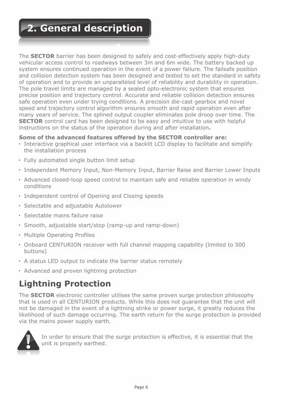
The SECTOR barrier has been designed to safely and cost-effectively apply high-duty vehicular access control to roadways between 3m and 6m wide. The battery backed up system ensures continued operation in the event of a power failure. The failsafe position and collision detection system has been designed and tested to set the standard in safety of operation and to provide an unparalleled level of reliability and durability in operation. The pole travel limits are managed by a sealed opto-electronic system that ensures precise position and trajectory control. Accurate and reliable collision detection ensures safe operation even under trying conditions. A precision die-cast gearbox and novel speed and trajectory control algorithm ensures smooth and rapid operation even after many years of service. The splined output coupler eliminates pole droop over time. The SECTOR control card has been designed to be easy and intuitive to use with helpful instructions on the status of the operation during and after installation.
Some of the advanced features offered by the SECTOR controller are: Interactive graphical user interface via a backlit LCD display to facilitate and simplify
the installation process
Fully automated single button limit setup
Independent Memory Input, Non-Memory Input, Barrier Raise and Barrier Lower Inputs
Advanced closed-loop speed control to maintain safe and reliable operation in windy conditions
Independent control of Opening and Closing speeds
Selectable and adjustable Autolower
Selectable mains failure raise
Smooth, adjustable start/stop (ramp-up and ramp-down)
Multiple Operating Profiles
Onboard CENTURION receiver with full channel mapping capability (limited to 500 buttons)
A status LED output to indicate the barrier status remotely
Advanced and proven lightning protection
Lightning Protection
The SECTOR electronic controller utilises the same proven surge protection philosophy that is used in all CENTURION products. While this does not guarantee that the unit will not be damaged in the event of a lightning strike or power surge, it greatly reduces the likelihood of such damage occurring. The earth return for the surge protection is provided via the mains power supply earth.
2. General description
Page 6
In order to ensure that the surge protection is effective, it is essential that the unit is properly earthed.

3. Specifications
FIGURE 1. OVERALL DIMENSIONS
Technical specifications
Physical dimensions
Page 7
11
67
mm
285mm437mm
304mm
20
mm
89
0m
m
Ø76mm
Input voltage
Motor voltage
Motor power supply
Battery charger
Current consumption (mains)
Boom pole length
Boom pole raise time (adjustable)
Manual override
Maximum number of operations per day
Duty cycle - mains present
Operations in standby with 7Ah battery
Half day
Full day
Collision sensing
Operating temperature range
Onboard receiver type
Receiver code storage capacity
Receiver frequency
220-240V AC ± 10%, 50Hz
12V DC
Battery driven (standard capacity - 7Ah)
CP84SM - 2A @ 13.8V
170mA
Allan key operated from outside unit
3000
80%
3000
3000
Electronic
-15°C to +65°C
CENTURION code-hopping multichannel
500 transmitter buttons
433MHz
SECTOR 3 SECTOR 4.5 SECTOR 6
3.0m
1.2 sec 3 sec3 sec
4.5m 6.0m
Can operate off a solar supply, consult Centurion Systems for assistance
Can increase battery capacity for longer standby times
Boom pole raise and lower times are both individually configurable to suit individual installation requirements
Based on 25°C ambient temperature and unit not in direct sunlight
Based on an output torque of less than 50% of rated
Based on basic operator excluding closing loop detector Limited by daily usage
Page 8
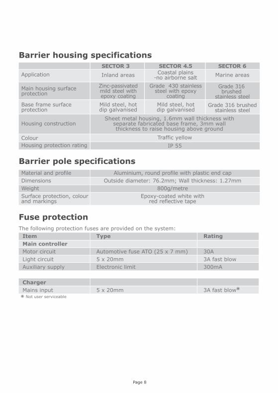
Fuse protection
The following protection fuses are provided on the system:
Item Type Rating
Main controller
Motor circuit Automotive fuse ATO (25 x 7 mm) 30A
Light circuit 5 x 20mm 3A fast blow
Auxiliary supply Electronic limit 300mA
Charger
Mains input 5 x 20mm 3A fast blow Not user serviceable
SECTOR 3
SECTOR 4.5 SECTOR 6
Barrier housing specifications
Application
Main housing surface protection
Inland areas Coastal plains-no airborne salt
Marine areas
Zinc-passivatedmild steel withepoxy coating
Grade 430 stainless steel with epoxy
coating
Grade 316brushed
stainless steel
SECTOR 3
Base frame surface protection
Mild steel, hot dip galvanised
Grade 316 brushedstainless steel
Mild steel, hot dip galvanised
Housing constructionSheet metal housing, 1.6mm wall thickness with
separate fabricated base frame, 3mm wall thickness to raise housing above ground
Traffic yellowColour
IP 55Housing protection rating
Barrier pole specifications
Material and profile
Dimensions
Weight
Surface protection, colour and markings
Aluminium, round profile with plastic end cap
Outside diameter: 76.2mm; Wall thickness: 1.27mm
800g/metre
Epoxy-coated white with red reflective tape

4. Icons used in this manual
This icon indicates tips and other information that could be useful during the installation
This icon indicates warning, caution or attention! Please take special note of critical aspects that MUST be adhered to in order to prevent injury
This icon denotes variations and other aspects that should be considered during installation
Page 9
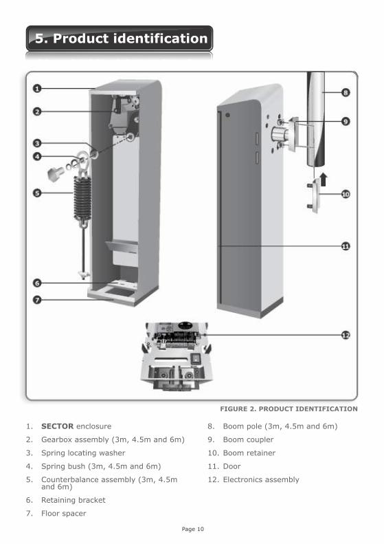
5. Product identification
FIGURE 2. PRODUCT IDENTIFICATION
Page 10
1. SECTOR enclosure
2. Gearbox assembly (3m, 4.5m and 6m)
3. Spring locating washer
4. Spring bush (3m, 4.5m and 6m)
5. Counterbalance assembly (3m, 4.5m and 6m)
6. Retaining bracket
7. Floor spacer
8. Boom pole (3m, 4.5m and 6m)
9. Boom coupler
10. Boom retainer
11. Door
12. Electronics assembly

6. Required tools and equipment
Spanner – 17mm; 13mm
Screwdriver – 3.5mm flat and 6mm Philips
Hammer
Electric drilling machine
G-clamp x 2
Pick
Crimping tool and pin lugs
Self-locking pliers (vice-grip)
Pliers
Side cutters
Masonry bits – 6mm; 20mm; (for sites with rawlbolt foundation plates)
Steel bits – 8.5mm; 5.0mm; 4.0mm
Spade
Spirit level
Measuring tape
Welding machine, including safety equipment and consumables
Angle grinder
Extension cord
Marking pen/pencil and chalk
Safety equipment, gloves, goggles, etc.
Page 11

7. Preparation of site
General considerations for the installation Consider the following checklist when determining the safety and suitability of the site:
Check that all local authority requirements will be met Check that the usage (duty cycle) of the site and the length of the boom pole
required, are within the barrier specifications Check that there is sufficient clearance on the side of the roadway to mount the
barrier Check that a suitable foundation has been prepared for the barrier Check that the fitment of additional safety equipment has been catered for Check that no pipes or electrical cables are in the way of the intended installation
Page 12
Page 13
8. Loop detectors and associated functionality
FLUX OB onboard vehicle loop detector
Description
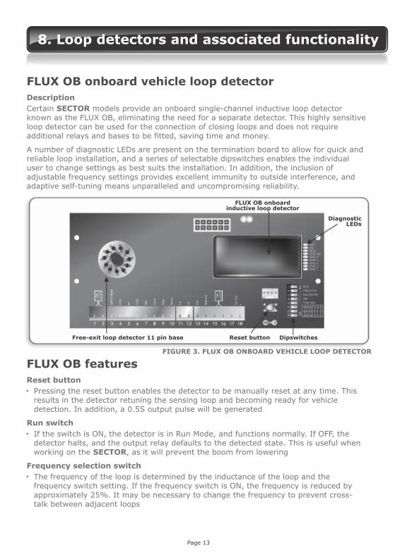
Certain SECTOR models provide an onboard single-channel inductive loop detector known as the FLUX OB, eliminating the need for a separate detector. This highly sensitive loop detector can be used for the connection of closing loops and does not require additional relays and bases to be fitted, saving time and money.
A number of diagnostic LEDs are present on the termination board to allow for quick and reliable loop installation, and a series of selectable dipswitches enables the individual user to change settings as best suits the installation. In addition, the inclusion of adjustable frequency settings provides excellent immunity to outside interference, and adaptive self-tuning means unparalleled and uncompromising reliability.
Free-exit loop detector 11 pin base Reset button Dipswitches
DiagnosticLEDs
FLUX OB onboardinductive loop detector
FLUX OB features
Reset button Pressing the reset button enables the detector to be manually reset at any time. This
results in the detector retuning the sensing loop and becoming ready for vehicle detection. In addition, a 0.5S output pulse will be generated
Run switch If the switch is ON, the detector is in Run Mode, and functions normally. If OFF, the
detector halts, and the output relay defaults to the detected state. This is useful when working on the SECTOR, as it will prevent the boom from lowering
Frequency selection switch The frequency of the loop is determined by the inductance of the loop and the
frequency switch setting. If the frequency switch is ON, the frequency is reduced by approximately 25%. It may be necessary to change the frequency to prevent cross-talk between adjacent loops
FIGURE 3. FLUX OB ONBOARD VEHICLE LOOP DETECTOR

Page 14
Uni-directional Free-exit switch
The switch is used to select between uni- and bi-directional traffic. If the switch is in the ON position, the loop detector will generate a “raise” pulse whenever a vehicle is detected on the Free-exit loop. If, however, the switch is in the OFF position, a raise pulse will only be generated if a detect signal is received from the Free-exit loop only, and never when a signal is received from the Free-exit loop and the closing loop simultaneously (bi-directional traffic)
It is very important that the distance between the free-exit loop and the closing loop is less than the length of one car
Automatic Sensitivity Boost (ASB) switch This option increases the sensitivity of the detector after initial detection of a vehicle.
This is useful to reliably detect vehicle and trailer combinations. Sensitivity returns to the selected value once the vehicle has been undetected
Permanent presence switch If this switch is set to the ON position, detection will be maintained as long as a vehicle
remains on the loop. The danger in using this setting is that any change in the environment (for example the introduction of metal into the vicinity of the loop) will not automatically be tuned out without pressing the reset button. If not selected, the loop will automatically tune out any permanent detection after five minutes
Adjustable loop sensitivity settings
Eight sensitivity settings are available
Sensitivity SENS1 SENS2 SENS3
High (0.03%) ON ON ON
0.06% ON ON OFF
0.1% ON OFF ON
0.2% ON OFF OFF
0.5% OFF ON ON
1% OFF ON OFF
2% OFF OFF ON
Low (4%) OFF OFF OFF
Power indicator LED This red LED is on when power is present, and the controller is functioning
Loop fault indicator LED This red LED is illuminated when there is a loop fault. If the loop is open circuit, the
Fault LED will flash continuously. If the loop is short circuit, it will remain on
Detection level indicator LEDs These five RED LEDs provide a visual indication of the Detection Level. Once all five
LEDs are on, the detection threshold is almost reached. This is a very useful feature to determine if the loop is going to perform reliably. With no vehicle in the vicinity, all the LEDs should be off

Page 15
FLUX OB diagnostics
The sense level LEDs flash erratically
The detector randomly detects, even though there is no vehicle present
The Loop Fault LED is flashing
The Loop Fault LED is permanently illuminated
There may be a poor connection in the loop or loop feeder
The detector may be experiencing crosstalk with the loop of an adjacent detector
Faulty loop or loop feeder wiring
Movement of the loop in the ground
The loop inductance is too large, or the loop is open circuit
The loop inductance is too small, or the loop is short circuited
Check all wiring. Tighten screw terminals. Check for broken wires
Try changing frequencies using the frequency switch. Put the detector with the larger loop onto low frequency and the detector with the smaller loop onto high frequency
Check the wiring. Tighten screw terminals. Check for pinched or bent wires. Is the feeder wire twisted?
Check for cracks in the road surface near the loop
Check that there is electrical continuity on the loop. If the inductance is too large then try reducing the number of turns
Check that there is no short circuit on the loop feeder wiring of the loop. If there is no short circuit then the inductance is too small and more turns of wire should be added to the loop
Symptom Possible cause Solution
Detect indicator LED This green LED indicator is illuminated when there is a vehicle detected. This LED can
also be used to determine the loop frequency. Reset or power up, count the number of times the Detect LED flashes. Multiply this number by 10KHz. For example: if the LED flashes eight times, then the loop frequency is approximately 80KHz
Commissioning the FLUX OB
1. With the loop connected, apply power to the SECTOR controller.
2. The green Power LED on the termination board will light up, and the green Detect LED will flash until the loop has stabilised, and then turn off.
3. Once the loop has stabilised, only the green power LED should be on.
4. Bring a metal object towards the loop, and the Sense level LEDs will begin to light up, indicating the detection range of the loop.
5. Once all five lights have lit up, the unit will enter detect, with the green detect LED lit.
6. Configure the desired operational settings using the dipswitches.
7. Test the FLUX OB using a metallic object, or a vehicle.

Page 16
Separate loop detector module If your SECTOR vehicle traffic barrier has not been fitted with an onboard inductive
loop detector, it is possible to install an external detector using one or both of the bases provided on the SECTOR termination board. Bases are provided for both Free-exit and closing loop connections. Setup will be as per the individual detector. For more information on the different configurations and Modes of Operation as well as connecting closing and Free-exit loops, please refer to section 15, Electrical Setup
12V loop detectors MUST be used.
Tips for successful loop installation The loop and feeder should be constructed from XLPE (cross-linked polyethylene)
insulated multi-stranded copper wire with a minimum cross-sectional area of 1.5mm². The feeder should be twisted at a rate of at least 20 turns per metre to improve reliability (Remember that twisting the feeder will shorten its length, so ensure a long enough feeder wire is used). Feeders which may pick up electrical noise should use screened cable, with the screen earthed at the detector
Joints in the wire are not recommended, but where required must be soldered and made waterproof
Faulty joints will lead to unreliable operation
The loop should be either square or rectangular in shape with a minimum distance of 1m between opposite sides
Two to six turns of wire are typically used in the loop – See table below:
Loop perimeter (metres)
3-4
4-6
6-10
10-20
>20
Number of turns
6
5
4
3
2
When two loops are laid in close proximity to each other, it is recommended that different numbers of turns are used in each loop to prevent cross-talk
Cross-talk describes the interference between two adjacent loops, and can cause reliability issues
To minimise cross-talk, adjacent loops should be at least two metres apart, and different frequency settings
The most reliable form of loop is preformed and enclosed in conduit. This prevents water ingress, and minimises the effects of vibration
Where a pre-formed loop is not practical, slots should be cut into the road using a masonry cutting tool. A 45° cut should be made across the corners to prevent damage to the wire on the corners. The slot should be about 4mm wide and 30mm to 50mm deep. Remember to extend the slot from one of the corners to the roadside to accommodate the feeder. After the loop and feeder wires have been placed in the slot, the slot must be filled with an epoxy compound or bitumen filler

Page 17
9. Select Operating Mode
There are four Modes of Operation which can be selected, namely Simplex, Complex, PLC and Spike
1. Simplex Mode Typical application would be the entrance to premises, which is controlled by a guard
Raising and lowering of the boom pole is done via pushbutton or remote control connected to the memory input (MI). The Autolower feature can be used to automatically lower the boom pole after an adjustable Autolower Time
In Simplex Mode, the MI input will have the following characteristics:
The input activates (the barrier responds) on the leading edge of the signal; in other words, the moment the button is pressed
From the fully lowered position, pressing the button once will cause the boom pole to raise. A second button press will result in the boom reversing direction. In other words, the action is: press to raise, press to lower and, if the barrier is in a semi- raised position, press to reverse - NB -The barrier cannot be stopped in a midway position.
The NMI input operates exactly in the same way as MI when the SECTOR is in Simplex Mode, but the input activates on the trailing edge of the signal, i.e. when the button is released
In Simplex Mode you can use standard infrared safety beams or a loop detector to prevent the barrier pole from being lowered onto a vehicle moving past the barrier. However, the closing loop is always recommended in preference to beams as it operates more reliably when used with barriers.
In this Mode of Operation, it will act purely as a safety loop and will not influence the closing of the barrier. However, the loop can be made to function as a closing loop if ILAC Mode is enabled.
ILAC Mode, which is comparable to PIRAC Mode as found on CENTURION gate motors, causes the boom to auto-lower as soon as the inductive loop is cleared, i.e. the vehicle moves off. This is a desirable action in high-security applications and is an effective deterrent to tailgating.
2. Complex Mode Typical application is any unmanned entrance, which makes use of any number of different access control devices to raise the boom pole
In Complex Mode, the boom pole lowers the moment the vehicle has driven over and cleared the closing loop, which is mounted below the boom pole
Access control devices, including proximity or card readers, keypads, remote controls, etc., are connected to the memory input (MI). In this instance, more than in Simplex Mode, the MI input can be seen as a “memory input” since it counts and stores the p ulses received and the barrier will only close once the corresponding number of activations and deactivations of the closing loop are received.
For example, say that someone presses the pushbutton three times to raise the boom, then it will be necessary for a vehicle to clear the closing loop three times before the boom will lower.

Page 18
If no closing signals are received, the boom will lower once the auto-lower time has expired. As with Simplex Mode described above, the input activates the moment that the button is pressed.
CENTURION recommends that an inductive loop detector, such as the one provided onboard, is used as the closing loop. This also acts as a safety loop while the vehicle is present on the loop detector. As an alternative, but not recommended is to use a set of infrared safety beams. It is recommended that two sets of safety beams are used, which are spaced about 500 millimetres apart.
There is a Non-Memory Input (NMI) to raise the boom pole when activated by a ticket vending machine, pay parking system, etc. In Complex Mode, the boom will always lower the first time that a closing signal is received, irrespective of how many trigger impulses were received on the NMI input. For example, even if the button is pressed twice, the closing loop will only need to be cleared once for the pole to lower. As with Simplex Mode, the input is activated once the button is released.
A ticket vend interlock is available via a potential-free contact to prevent the issuing of tickets if the boom pole is raising or raised. These contacts can also be used as a potential-free contact for courtesy or security lights that illuminate automatically when the barrier is operated and remain illuminated for an adjustable period of time afterwards.
2a. Free-exit (typically applicable to Complex Mode) It is possible to use the free-exit facility on the controller to automatically raise the barrier for vehicles exiting the parking area or premises
It is recommended to use an Inductive Loop Detector to activate the free-exit facility. Alternatively, a set of infrared safety beams may be used, but this is not recommended
The system can be configured for uni-directional traffic with the barrier dedicated as a free-exit barrier. The closing loop will be used to lower the barrier the moment the vehicle has exited
It can also be configured for bi-directional traffic with the same barrier providing access control for vehicles entering and free-exit for vehicles exiting. The free-exit loop must be mounted close enough to the closing loop so that the vehicle exiting is still present on this loop when it reaches the closing loop. However, these must not be too close together, or magnetic interference will be caused
3. PLC mode In this Mode of Operation, separate inputs are controlled via pushbutton or directly from a third-party programmable logic controller or PC to raise, lower and stop the barrier
There is one safety input for use with an Inductive Loop Detector or infrared safety beams to prevent the boom pole from lowering onto a vehicle
4. Spike mode The Mode of Operation will only be enabled if the controller is used as a CLAWS controller and will never be used on a stand alone SECTOR.
The purpose of Spike Mode is simply to switch controller functionality to drive CLAWS

Page 19
The cable requirements differ according to the mode that you have selected.
10. Cabling requirements
All cables must be routed in conduit unless underground cable is being used
For the detection of vehicles, CENTURION recommends installing Inductive Loop Detectors in preference to infrared beams
1. Simplex Mode
Guard hut
Courtesy light
To mains supply
Direction of travel
Direction of travel
3a. Free-exit for uni-directional traffic
2. Complex Mode (basic)
Direction of travel
FIGURE 4. SIMPLEX MODE CABLING
FIGURE 5. COMPLEX MODE CABLING
FIGURE 6. FREE-EXIT FOR UNI-DIRECTIONAL TRAFFIC CABLING
Page 20
Legend
2 1. 220-240V AC mains cable (three core LNE 1.5mm SWA ) 22. Pushbutton control (two core 0.5mm multi-stranded)
23. Infrared safety beams (three core 0.5mm multi-stranded)
4. Optional Pillar Lights (three core LNE SWA , size according to power requirements) 25. Inductive loop Detector for closing or safety (one core 0.5mm multi-stranded
silicone-coated)26. Access control device (two core 0.5mm multi-stranded )
7. Inductive Loop Detector for free-exit (one core 0.5mm multi-stranded - silicone coated)
Type of cable must adhere to municipal bylaws but typically SWA (steel wire armoured) cable is recommended. The armouring provides excellent screening, which gives better protection against lightning – earth one end of the screening
Consult manufacturer of loop detector for specific details, or refer to page nine for information on the FLUX OB onboard inductive loop detector
Number of cores and type of cable could vary depending on brand of access control system being used
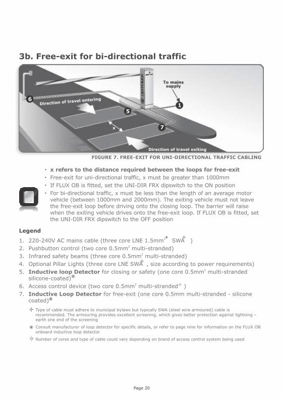
3b. Free-exit for bi-directional traffic
x refers to the distance required between the loops for free-exit Free-exit for uni-directional traffic, x must be greater than 1000mm If FLUX OB is fitted, set the UNI-DIR FRX dipswitch to the ON position For bi-directional traffic, x must be less than the length of an average motor
vehicle (between 1000mm and 2000mm). The exiting vehicle must not leave the free-exit loop before driving onto the closing loop. The barrier will raise when the exiting vehicle drives onto the free-exit loop. If FLUX OB is fitted, set the UNI-DIR FRX dipswitch to the OFF position
Direction of travel exiting
Direction of travel entering
7
5
6
x
FIGURE 7. FREE-EXIT FOR UNI-DIRECTIONAL TRAFFIC CABLING

Page 21
It is always recommended to mount the barrier with its access door facing the oncoming traffic. This ensures that if a vehicle accidentally hits the pole, the pole is knocked away from the barrier housing, not back onto the barrier housing, potentially damaging the housing.
11. Orientation
Left Hand A Left Hand barrier is defined as a unit installed on the left hand side of the road from
which the vehicle approaches. The door always faces oncoming traffic.
Changed orientationLeft hand orientation
It is possible to change to left hand orientation allowing the barrier to be mounted on the left hand side of the roadway with the pole pointing to the right. See Section 12 for details
Internal view of barrier
Lefthand configuration when the pole is in the raised position
Boom pole
Boom pole
FIGURE 8. LEFT HAND ORIENTATION
FIGURE 9. LEFT HAND ORIENTATION
FIGURE 10. INTERNAL VIEW

Page 22
Right Hand A Right Hand barrier is defined as a unit installed on the right hand side of the road
from which the traffic approaches. The door always faces oncoming traffic.
Internal view of barrier
Right hand configuration when the pole is raised at up-right position
The default orientation is the operator on the right hand side of the roadway, with the pole pointing to the left - also referred to as right hand orientation
Accessdoor
FIGURE 11. RIGHT HAND ORIENTATION
FIGURE 12. RIGHT HAND ORIENTATION
FIGURE 13. INTERNAL VIEW
Boom pole
Boom pole

Page 23
12. Conversion from right hand to left hand
Remove the counterbalance spring1. Remove the boom pole.
2. With the door and electronics assembly removed, make sure the spring is under minimum tension. To achieve this, it is advisable to have the boom pole in the raised position.
3. Loosen the tension bar nut until the taper bush can rotate freely below the cross beam.
4. Remove the counterbalance spring.
Convert6. Remove the counterbalance spring pivot.
7. Fit the pivot and related parts to the hole in the output plate designated for the LH configuration.
Fit the counterbalance spring9. Push the taper bush through the slot in the cross beam and rotate it 90° so that it sits perpendicularly across the beam.
10. Fit the counterbalance assembly.
11. Tighten the tension bar nut.
Remove the boom coupler12. When changing the configuration of the barrier from right hand to left hand or vice versa, the boom coupler will be out of sequence and needs to be removed, rotated and then refitted.
150mm
55mm 55mm
10(X3)
Steel angle25 x 25 x 4
13. Use the coupler puller shown in Figure 14 to remove the coupler
FIGURE 14. COUPLER PULLER
Page 24
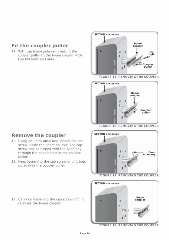
Remove the coupler15. Using an 8mm Allan Key, loosen the cap screw inside the boom coupler. The cap screw can be turned with the Allan Key through the middle hole in the coupler puller.
16. Keep loosening the cap screw until it buts up against the coupler puller.
17. Carry on loosening the cap screw until it releases the boom coupler.
FIGURE 15. REMOVING THE COUPLER
FIGURE 16. REMOVING THE COUPLER
FIGURE 17. REMOVING THE COUPLER
FIGURE 18. REMOVING THE COUPLER
SECTOR enclosure
Couplerpuller
M8bolt
Couplerpuller
8mm Allan key
Boom coupler
Boom coupler
SECTOR enclosure
SECTOR enclosure
SECTOR enclosure
Boom couplerFit the coupler puller
14. With the boom pole removed, fit the coupler puller to the boom coupler with two M8 bolts and nuts.

Page 25
Fit the coupler
18. With the counterbalance assembly under minimum tension – i.e. with the boom pole in the raised position – fit the boom coupler.
19. Engage the boom coupler/output shaft splines so that the boom coupler is in its closest vertical position.
20. Fit the washer and cap screw and then tighten using an 8mm Allen Key.
Boom coupler
Boom coupler
SECTOR enclosure
SECTOR enclosure
Boom coupler
8mm Allan key
Washer
Cap screw
FIGURE 20. FITTING THE COUPLER
FIGURE 21. FITTING THE COUPLER
FIGURE 22. FITTING THE COUPLER

Page 26
13. SECTOR installation
The dotted line denotes recommended dimensions of the concrete foundation
Enclosure positioning
Check orientation of the door
Concrete plinth/foundation
1. Determine correct position for the barrier to be installed.
Cable entry
Holdingdownbar
Accessdoor
2. Prepare hole for concrete foundation.
3. Install cable conduits, making sure that the conduits exit in cable entry area, leaving approximately 50mm of conduit protruding above the concrete
4. Concrete in anchor bolts or fit shield anchor rawl bolts later (size M12 x 70).
SECTOR barrier
Concretefoundation
FIGURE 23. CONCRETE FOUNDATION
FIGURE 24. ORIENTATION
FIGURE 25. CONCRETE FOUNDATION
FIGURE 26. ANCHOR BOLTS

The enclosure is clamped down between the holding down bar and the concrete plinth
Page 27
Holding down bar
Cableconduits
5. Align the enclosure and make sure the two anchor bolts go through the holes on the holding down bar as shown in Figure 27.
Fitting the boom pole
6. Use the boom pole retainer piece as a ruler to mark a straight line on the boom pole.
Boom pole
Boomretainer
Spring washer
and nuts
Boom coupler
7. Mark and drill the 8.5mm holes in the boom pole according to the measurements.
8. Slide the boom pole retainer piece into the boom pole and push the mounting bolts through the drilled holes.
9. While holding the boom pole retainer piece in position, fit the boom pole onto the boom coupler.
10. Fit the M8 spring washers and nuts onto the bolts and tighten.
It is recommended that the Boom Pole is fitted when the Boom Coupler is in the vertical (raised) position.
Concrete plinth
FIGURE 27. CLAMPING THE ENCLOSURE
Anchor bolt
FIGURE 28. MARKING THE POLE
FIGURE 29. DRILLING HOLES
FIGURE 30. FITTING THE POLE

Page 28
Levelling the boom pole1. Using a 17 spanner, loosen the lock nuts on the adjustment link.
2. Turn the adjustment link to level the boom pole.
3. Tighten the lock nuts.
1. Should the spring not be properly balanced, the onboard buzzer will alert the user to this fault condition.
2. A handy diagnostic screen, complete with graphic representation, can be found by simply pressing the down arrow once while in normal operating mode.
3. This screen will show the user exactly how many turns of the tensioning nut are needed to obtain optimum balancing of the counterbalance spring and in which direction.
4. The barrier must be operated at least three times before the new adjustments will be registered by the controller.
5. It is much easier to perform the tensioning operation while the boom pole is in the vertical (raised) position, as the spring will be under significantly less tension.
Both of the lock nuts will loosen/tighten in the same direction. This might not be the expected direction - if the lock nut does not loosen/tighten try the other direction
Balancing the Spring
As the adjustment link is turned, the boom pole moves up or down. It is helpful to hold the adjustment link with a second spanner during this process
On the 6m and 4.5m SECTOR variants, a 24mm socket must be used on the tensioning nut, and a 19mm socket must be used for the 3m SECTOR
FIGURE 31. GEARBOX ASSEMBLY
FIGURE 31. BALANCING
FIGURE 32. BALANCING THE SPRING
Boom pole
SECTOR enclosure
Spring
Gearbox assembly

Page 29
Failsafe/Lock mode Top locking stop
Bottomlocking
stop
1. When the barrier is in Failsafe mode, the boom pole can be manually moved by hand.
2. In Lock mode, the boom pole is locked in the raised or lowered position and cannot be moved by hand.
3. These configurations are implemented by setting the top and bottom locking stops on the gearbox in different positions.
In the event of a system failure the boom pole can be raised or lowered by hand
When the barrier is in Lock Mode it can be manually released as follows:
1. Insert the 8mm Allen Key (provided) into the release socket.
2. Turn the Allen Key to release the barrier, and then move the boom pole to the raised position by hand.
3. To lock the boom pole in the raised position, rotate the release socket (using the Allen Key)in the same direction as above until it stops.
Manual release
FIGURE 33. LOCKING
FIGURE 34. HAND OPERATION
FIGURE 35. HAND OPERATION
8mmAllen key
SECTOR enclosure
Boom pole

14. Electrical setup
1. Always check that the circuit breaker in the electrical panel is in the OFF position, and that all high voltage circuits (more than 42.4V) are completely isolated from the mains supply before doing any work. The pole must be raised before isolating system.
2. Ensure that all low voltage systems (less than 42.4V) are suitably protected from damage, by disconnecting all sources of power such as chargers and batteries before doing any work.
3. All electrical work must be carried out according to the requirements of all applicable local electrical codes. (It is recommended that a licensed electrical contractor perform such work).
Page 30
Connect all wiring
1. Connect all cables as required for the specific installation.
2. Ensure all interconnecting cables are securely in place.
3. Ensure single phase mains power is connected to the system.
4. Switch on the mains (isolator and circuit breaker), make sure that the battery is connected and check that the polarity is correct.
The wiring diagrams on page 11 begin connection at the termination board, and not the controller
SECTORcontroller
Free-exit loop detector base
SECTOR termination board
incorporating FLUX OB
FIGURE 36. ELECTRONICS ASSEMBLY

15. Simplex Mode: Option 1 (Recommended) - electrical connections
OPTION 1
SOLO or Latticeproximity accesscontrol system
COM
N/O
OPTION 2
CENTURION transmitter with onboard receiver
SMARTGUARDkeypad
COM
N/O
External CENTURION
receiver
COM
N/O
Normally-openPushbutton
COM
N/O
Page 31
12V+
OPTION 3
12V-
OPTION 4
OPTION 5
Safetyloop
FIGURE 37. SIMPLEX MODE ELECTRICAL WIRING
12V+
12V-
12V+
12V-

Page 32
Option 1
All connections are made to the termination board and NOT the controller (Refer to page 8)
The different inputs to and outputs from the termination board, react according to the following when Simplex Mode is selected:
MI: In this mode, the memory input acts simply to raise and lower the boom pole with sequential activations
Lower: A dedicated input to only lower the boom pole
Raise: A dedicated input to only raise the boom pole
TVI: Potential-free contact that can be used for a courtesy or security light. The light illuminates when the barrier is operated and remains switched on for an adjustable period of time after the boom pole has lowered
Close (closing loop): The FLUX OB onboard loop detector can be used or a closing loop detector must be fitted. In addition to sensing when the vehicle has passed the barrier for closing purposes, it will act as a safety loop preventing the boom pole from being lowered onto a vehicle present on the loop

Page 33
Safe
ty
Bea
m
FR
X
CO
M
MI
CO
M
2 3 41 5N
MI
Low
er
Rais
e
Sta
tus
TVI
TVI
LCK
-12
V O
ut
+1
2V
Out
AU
X O
ut
Clo
se
7 8 9 10 13 1411 126 15 16 17 18
OPTION 1
SOLO or Latticeproximity accesscontrol system
COM
N/O
1 2abc
3abc
3Efg
4Hij
5klm
6nop
7qrs
8tuv
9wxvz
10* #
OPTION 2
CENTURION transmitter with onboard receiver
SMARTGUARDkeypad
COM
N/O
External CENTURION
receiver
COM
N/O
Normally-openPushbutton
COM
N/O
12V+
12V-
+_
12V+
12V-
12V+
OPTION 3
12V-
OPTION 4
OPTION 5
Safetyloop
NL
Courtesylight
Earth
L N E
Two pole mains
isolator
L N
AC supply220V AC 50HZ
ON
OFF
16. Simplex Mode: Option 2 - electrical connections
Tra
nsm
itte
r
Rece
iver
12
V+
12
V+
12
V-
12
V-
Infraredbeams
Rx Tx
FIGURE 37. SIMPLEX MODE ELECTRICAL WIRING
CO
M
N/C

Page 34
Option 2
All connections are made to the termination board and NOT the controller (Refer to page 8)
The different inputs to and outputs from the termination board, react according to the following when Simplex Mode is selected:
Safety Beam: Infrared safety beams can be used as an alternative to an inductive loop, but not recommended
MI: In this mode, the memory input acts simply to raise and lower the boom pole with sequential activations
Lower: A dedicated input to only lower the boom pole
Raise: A dedicated input to only raise the boom pole
TVI: Potential-free contact that can be used for a courtesy or security light. The light Illuminates when the barrier is operated and remains switched on for an adjustable period of time after the boom pole has lowered

Page 35
17. Complex Mode: Option 1 (Basic) - electrical connections
Safe
ty
Bea
m
FR
X
CO
M
MI
CO
M
2 3 41 5N
MI
Low
er
Rais
e
Sta
tus
TVI
TVI
LCK
-12
V O
ut
+1
2V
Out
AU
X O
ut
Clo
se
7 8 9 10 13 1411 126 15 16 17 18
OPTION 1
COM
N/O
COM
N/O
COM
N/O
12V+
OPTION 2
12V-
OPTION 3
Safetyloop
NL
Courtesylight
Earth
L N E
Two pole mains
isolator
L N
AC supply220V AC 50HZ
ON
OFF
Magnetic card reader
Memory input
SOLO or Latticeproximity accesscontrol system
1 2abc
3abc
3Efg
4Hij
5klm
6nop
7qrs
8tuv
9wxvz
10* #SMARTGUARD
keypad
FIGURE 38. ELECTRICAL WIRING
12V+
12V-
12V+
12V-

Page 36
Option 1: Basic
All connections are made to the termination board and NOT the controller (Refer to page 8)
The different inputs to and outputs from the termination board, react according to the following when Complex Mode is selected:
Safety Beam: Although not recommended, this input can be used if a closing loop detector is not fitted. It is recommended that two safety beams are used, which are spaced about 500 millimetres, horizontally apart
MI: The memory input counts and stores each trigger impulse. The boom pole will stay raised until the same number of closing signals are applied to the closing input , or the Autolower time expires
NMI: Typically used with ticket vending machines – refer to Option 2
Lower: A dedicated input to only lower the boom pole
Raise: A dedicated input to only raise the boom pole
TVI: Potential-free contact that can be used for a courtesy or security light. The light illuminates when the barrier is operated and remains switched on for an adjustable period of time after the boom pole has lowered
Close (closing loop): The FLUX OB onboard loop detector can be used or a closing loop detector must be fitted. In addition to sensing when the vehicle has passed the barrier for closing purposes, it will act as a safety loop preventing the boom pole from being lowered onto a vehicle present on the loop

Page 37
18. Complex Mode: Option 2 (Ticket vend) - electrical connections
Safetyloop
Ticket Vend
Option 2: Ticket vending entry points
All connections are made to the termination board and NOT the controller (Refer to page 8)
The different inputs to and outputs from the termination board, react according to the following when Complex Mode is selected:
Safety Beam: Although not recommended, this input can be used if a closing loop detector is not fitted. It is recommended that two safety beams are used, which are spaced approximately 500 millimetres, horizontally apart
MI: Typically not used
NMI: Non-memory input responds only when the trigger signal to the input is removed. It does not react when the signal is given. Connect to the trigger output from the ticket vending machines
Lower: A dedicated input to only lower the boom pole
Raise: A dedicated input to only raise the boom pole
TVI: Ticket Vend Interlock is a potential-free output that prevents the ticket vending machine from issuing another ticket until the boom pole is closing or is closed
Close (closing loop): The FLUX OB onboard loop detector can be used or a closing loop detector must be fitted. In addition to sensing when the vehicle has passed the barrier for closing purposes, it will act as a safety loop preventing the boom pole from being lowered onto a vehicle present on the loop
FIGURE 39. ELECTRICAL WIRING

Page 38
19. Free-exit loop - electrical connections
Option A: Free-exit single lane, unidirectional traffic (Refer to page 19)
All connections are made to the termination board and NOT the controller (Refer to page 30)
Please note the following:
FRX: The free-exit loop detector must be fitted. The free-exit loop can be positioned any distance away from the closing loop, typically no less than 1000 millimeters, otherwise it may cause magnetic interference
Proceed to Menu level 6.3 and set the free-exit loop direction to UNI
Safety Beam: Although not recommended, this input can be used if a closing loop detector is not fitted. It is recommended that two safety beams are used, which are spaced approximately 500 millimeters horizontally apart
Close (closing loop): The FLUX OB onboard loop detector can be used or a closing loop detector must be fitted. In addition to raising the boom and sensing when the vehicle has passed the barrier for closing purposes, it will act as a safety loop preventing the boom pole from being lowered onto a vehicle present on the loop
If FLUX OB is fitted, set the UNI-DIR FRX dipswitch to the ON position
FIGURE 37. ELECTRICAL WIRING

Page 39
20. Setting up the limits and features for the SECTOR barrier
Menu levelMenu levelMenu level
Setting up the limits
When setting up the SECTOR barrier system via the LCD display, all the steps that have to be followed are clearly provided via the display. It is only necessary to note the following:
Press and hold the oblong enter ( ) button for two seconds to enter Setup Mode
If powering up for the first time (ex-factory), select the required profile that will suit the specific region (ZA - for South Africa, CE - for Europe and UL325 - for North America/Canada )
With this set, the system will automatically proceed to the limit setup menu. Follow the on-screen instructions to complete the setup procedure
If powering up at any stage after this, press and hold the oblong enter ( ) button for two seconds
Select the Limits Menu by pressing the oblong enter ( ) button. Follow the onscreen instructions to complete the setup procedure
The profile is compliant with UL325, but the barrier is not certified
Setting up additional features for the SECTOR barrier
The SECTOR navigation map that follows, provides the full menu of features that can be set up on the system.
A brief explanation of each feature is provided in the section, ‘Controller features’.
When setting up additional features, all the steps that have to be followed are clearly provided via the display. It is only necessary to note the following:
To get into Setup Mode, press the oblong enter ( ) button for two seconds and follow the onscreen instructions
The buttons provided on the controller for navigating the system, are not marked because at each step during the setup, the function given to each button is provided on a new or defaulted controller, the LCD will display the default on the display
FIGURE 38. SECTOR CONTROLLER

Page 40
When not in Setup Mode, ie Normal Mode, the round ( ) button is used as a test button for operating the system. The up/down buttons are not used unless the diagnostic screens have been selected to appear in normal mode, in which case these buttons allow switching from one screen to the next
For each feature a Factory Default setting has been programmed into the controller. Referred to as an Operating Standard or Profile, these defaults have been determined to suit the requirements of the specific region where the installation is being carried out. It is only necessary to change a feature where the default does not suit the installation. When selecting any feature in the menu, details of the current setting stored in the controller are displayed
When selecting any of the features on a new or defaulted controller, the LCD will display the default value

Page 41
1.1. Setup wizard1. Setting limits
2.1.1. Raise collision force
2.1.2. Lower collision force
2.5.1. Indicator output
2.5.2. Lowered indication
2.5.3. Partly lowered indication
2.5.4. Lowering indication
2.5.5. Partly raised indication
2.5.6. Raising indication
2.5.7. Raised indication
2.5.8. Unknown indication
3. Autolower
3.1. Autolower status
3.2. Autolower timer
3.3. Autolower override
3.4. Autolower advanced 3.4.1. Autolower fully raised
3.4.2. Autolower partly raised
3.4.3. Autolower partly lowered
2. Safety
2.1. Collision force
2.2. Collision count
2.3. Alarm output
2.4. LCK input as ESTOP
2.5. External boom status indication
4. Modes of Operation
4.1. Operating mode
5. Run profile
5.1. Lock boom at endpoints
5.2. Raise when mains fail
5.3 Spike Interface
5.4 Pre-raising delay
5.5 Pre-lowering delay
5.6 Raising speed
5.7 Lowering speed
5.8 Ramp-up distance
5.9 Ramp-down distance
5.10 TRG stop distance
5.11 Loop stop distance
5.12 Crawl distance
5.13 Torque limit
5.1.1. Lock when raised
5.1.2. Lock when lowered
5.1.3 Holding force
21. SECTOR menu navigation map

Page 42
6. Loop detector
6.1. ILAC control
6.2 ILD input to Aux Out
6.3. Rollback time
6.4. FRX loop direction
6.5. Inductive loop alarms 6.5.1.1.Presence alarm
status
6.5.1.2.Presence time function
6.5.1. Presence alarm
6.5.2. Break-in alarm
6.5.3. Alarm output
6.4.1. Presence alarm
6.4.2. Break-in alarm
6.4.3. Alarm output
7. TVI output
7.1. TVI output function
7.2. TVI output polarity
7.3. Light timer
7.4. Light profile
8. ChronoGuard
8.1. Time and date
8.2. Time-periods
8.3. Exclusions
8.4. Delete all Time- periods and exclusions
8.2.1. Add Time-period
8.2.2. Delete Time-period
8.2.3. Edit review Time- period
8.3.1. Add exclusion
8.3.2. Delete exclusion
8.3.3. Edit review exclusion
8.2.1.1.Auto-function
8.2.1.2.Time-bar function
8.3.1.1.Auto-function
8.3.1.2.Time-bar function
9. General settings
9.1. Operating standard
9.2. Reset options
9.3. Diagnostic screen status
9.4. Round test button status
9.5. Backup eeprom
9.6. Restore eeprom
9.2.1. Factory defaults
9.2.2. Delete all remotes
9.2.3. Delete all Time Periods and exclusions
9.2.4. Reset all

Page 43
10. Remote controls
Press button of valid transmitter (if menu locked)
10.1. Add remotes
10.2. Delete remotes
10.3. Edit remote button
10.4. Autolearn remotes
10.5. Tx menu locked
10.6. Onboard receiver enable/disable
10.2.1.Delete by ID
10.2.2.Delete button
10.2.3.Delete by button
10.2.4.Delete-Not-Present
10.2.5.Delete all remotes

Page 44
22. SECTOR controller features
Menu 2 - Safety (collision force) Collision force
The collision force can be set independently for raising or lowering from minimum to maximum in five discrete steps. A sixth step will disable collision sensing entirely, allowing maximum force to be achieved. The motor will only shut down when its stall point is reached. Stall level is adjustable, refer to Torque Limit under Menu 5.
The response of the system to a collision will vary, depending on the Operating Standard (eg. CE, UL325 ) selected Collision force setting satisfies UL325, but the SECTOR barrier itself is not certified
Menu 3 - Autolower Autolower Status
If enabled, the boom pole will automatically lower after a preset Autolower time
Autolower Time The Autolower time can be set anywhere from 1 to 240 seconds (four minutes)
Autolower OverrideTemporarily turn off Autolower. Activate and maintain the memory input for longer than the Autolower Override Time. Activate Memory input to clear the override.
Autolower Advanced OptionsSet the conditions under which the boom pole will automatically lower. More than one condition can be selected:
Autolower on Raised - automatically lower the boom if boom pole is fully raised
Autolower on Partly Raised - automatically lower the boom pole if it has been stopped partially raised
The maximum force setting should only be used if additional safety measures are taken, for example, inductive loops, etc.
Collision count The number of sequential collisions that the system will allow, before shutting down the controller, if the boom pole does not reach the lowered position. Counter resets each time the boom pole reaches lowered position. A valid trigger input will clear the shutdown
Alarm outputAn alarm is activated if the multiple collision shutdown is triggered. This menu item configures the different alarm outputs
LCK as ESTOPAllows the Lck (Holiday Lockout) input to be configured as an emergency stop input
External boom statusGenerates an output indicating specific states of the boom

Page 45
Autolower on Partly Lowered - automatically lower the boom pole if it has been stopped partially lowered
Menu 4 - Modes of Operation
Refer to “Select Operating Mode” on page 17 for an explanation of the four different Modes of Operation available: Simplex, Complex, PLC and Spike.
Menu 5 - Run profile
Refer to “Select Operating Mode” on page 17 for an explanation of the four different Modes of Operation available: Simplex, Complex, PLC and Spike.
Lock boom pole at endpoints:
Lock When Raised - mechanically lock boom pole in raised position. Use manual override key to override
Lock When Lowered - as per above for lowered position
The locking endstops must be accordingly set for locking to take effect. Refer to installation manual
Holding Force - force used to automatically hold the boom pole in the raised or lowered position if “lock at endpoints” is not selected
Raise When Mains FailIf enabled, the boom pole will raise in event of a mains power failure. Boom pole will remain raised until mains power is restored
Spike Interface If enabled, this facility allows the SECTOR controller to communicate with co-installed roadway spikes, such as CLAWS.
Pre-raising DelayAllows a delay between a valid trigger signal and the boom pole raising. Can activate warning light during delay if TVI is not selected. (Refer to pre-flash modes of the Courtesy Light feature, for more details.)
Pre-lowering DelayIdentical to above, except for boom pole lowering
Raising SpeedSets the maximum raising speed in degrees per second
Ramp-up DistanceSets the ramp-up distance in degrees
Ramp-down DistanceSets the ramp-down distance in degrees of travel of the boom pole when stopping
TRG Stop DistanceSets the distance over which a moving boom pole will stop after a trigger signal is received

Page 46
Menu 6 - Loop detector ILAC (Inductive Loop Autoclose) Control
Causes the boom to Autolower as soon as the closing inductive loop is cleared, ie. the vehicle moves off
FRX (Free-exit) Loop DirectionAllows a single access point with bi-directional traffic to make use of a free-exit loop. Due consideration must be given to closing and free-exit loop positioning
Loop Alarms While the boom pole is lowered, this feature allows the following alarms.
Presence Alarm - Activates an alarm if the closing loop has been continuously activated for a predefined time. The alarm will remain activated while the closing loop is activated
Presence Time - The time for which the closing loop must be continuously activated before the alarm is activated
Break-in Alarm - Activates an alarm if the closing loop is activated while the boom is lowered. The alarm remains active while the closing loop is activated, and for a period of 30 seconds thereafter. This time is fixed
Alarm Output - This menu item configures the different alarm outputs
Crawl DistanceSets the final crawl distance in degrees of travel of the boom pole when reaching an endpoint
Torque LimitSets the maximum torque delivered by the motor. This is useful in cases where limited push force is required
Loop Stop DistanceSets the distance over which a moving boom pole will stop after a safety input is triggered
Menu 7 - TVI (Ticket Vend Interlock) output
Configure TVI output for the specific purpose or as a Courtesy Light. If configured as a Courtesy Light, light will switch on for a timed period every time the boom is activated.
TVI Output PolarityConfigure output as a normally-closed (NC) or normally- open (NO) contact
The TVI output when configured to Courtesy Light timeThe Courtesy Light time can be set from four seconds to ten hours
The TVI output when configured to light profileSelect operation of Courtesy Light according to four different modes

Page 47
Menu 8 - ChronoGuard (Time-periods)(a world first)
ChronoGuard allows automatic activation or time-barring (prevented operation) of specific controller inputs, and the time-barring of specified remote control buttons used together with the onboard receiver. The Real Time Clock and Calendar will keep time for a minimum of one hour without any power.
Time-periodsA Time-period is defined by a start and end date and time. Up to 100 Time-periods can be defined. A Time-period can be set as a once-off event, repeated on a weekly or annual basis. The weekly repeat can be chosen to occur on every day of the week, weekdays only, weekends only, or any specific day. The minimum duration of a Time-period is one minute. Once-off Time-periods have the highest precedence, followed by annual and then weekly. Auto-functions (Auto-activations)
Activate automatically any of the following inputs/outputs during a Time-period
Inputs Barrier Raise Barrier Lower Barrier Disable (Lck) - also referred to as Holiday Lockout Closing Loop (ILD)
Outputs Aux Out - this is a switching negative that can be used to drive an external
relay for operating any eternal device Aux IO - this is a switching negative that can be used to drive an external
relay for operating any eternal device
Time-barring Time-barring of inputs is divided into physical inputs and inputs mapped to a
remote control button. The following physical inputs can be time-barred (prevented from operating)
during a Time-period: Barrier Raise Barrier Lower Memory Input (MI) Non-memory Input (NMI) Barrier Disable (LCK)
The following physical outputs can be time-barred (prevented from operating) during a Time- period:
TVI (configured as a Courtesy Light Relay)
The following remote control inputs can be time-barred (prevented from operating ) during a Time-period: Barrier Raise Barrier Lower Memory Input (MI) Non-memory Input (NMI) Barrier disable (LCK)

Page 48
Time-barring of a CENTURION NOVA code-hopping transmitter is specified at the time of coding the transmitter into the system. Once an RF input is defined as time-barred, any time-barred transmitter associated with that input will be time-barred during the relevant Time-period. If a physical or RF input is currently time-barred, any attempt to activate it will be acknowledged by a short beep of the onboard buzzer. The input, however, will not activate
Exclusions Exclusions are used to prevent scheduled Time-periods from occurring at
specific times (eg. public holidays). While time-barring can be used to achieve a similar end, exclusions can also be used to exclude time-barring itself. Each exclusion consumes one Time-period. Exclusions have the highest precedence, followed by time-barring and then Auto-functions
Menu 9 - General settings Operating Standard
Configure the controller to conform to the specific region’s standard - e.g. UL325 or CE.
Reset options
Factory Defaults - Restore only defaults for the operating standard / profile chosen, no other settings affected
Delete All Remotes - Delete all the remotes stored in the system; no other settings affected
Reset All – Clears the controller completely as per an off-the-production-line unit
Boom pole end-of-travel limits are not affected by any reset
Diagnostic Screen Allows a diagnostic screen to be displayed.
Round Test Button Disables operation of the round test button on the controller
Menu 10: Remote controls
Learn up to 500 CENTURION NOVA remote control transmitter buttons. Using one button as a shift button, each transmitter can operate up to six functions. Each transmitter learned into the system is assigned a unique transmitter ID. When adding transmitters, it is recommended that a record be kept of the ID number allocated by the system to each respective transmitter and the person to whom the transmitter is given. This is necessary should selective deletion be required at a later stage. Press button of valid transmitter If the remote controls menu has been locked as discussed later, only by pressing a button of a transmitter learned into the system, can this remote controls menu be accessed

Page 49
Add RemoteAny button can be set to control the memory, non-memory, raise boom pole, lower boom pole and Holiday Lockout inputs
Delete RemoteTransmitters can be deleted at any stage according to one of the following:
Delete Remote by ID – Where a record of the unique ID has been kept, delete transmitter according to this
Delete Remote Button – Clear operation of a button on a particular transmitter
Delete Remote by Button - Delete a transmitter that is present
Delete-Not-Present - Allows a Time-period to be set in hours. Any remotes which have not been used in the Time-period will be deleted
Delete All Remotes – Clear the entire remote memory
Edit Remote ButtonMove the function from one button to another. The transmitter must be present
Autolearn
Allows a Time-period to be set, during which any specific button will be learned to a specific function when it is pressed. The function will also be activated when the button is pressed. After the Time-period has expired, Autolearn is disabled, and no further buttons will be learned.
Tx Menu LockedLock the “Remote controls” menu and prevent unauthorized addition of new transmitters. Once enabled, the “Remote controls” menu can only be accessed by pressing a valid transmitter button
It is possible to artificially increase the number of buttons of a multi-button transmitter by using a two button combination
One of the buttons is used as a shift button to allow the other buttons to be used again in combination with this button. In other words the user will press and hold the shift button, before pressing one of the other buttons to create a new button
The shift button cannot be used as a button on its own, it must always be used in combination with the other buttons
Benefits of the shift button system: Use of the shift button system allows a three button transmitter to
gain an extra button and operate four functions and likewise a four button transmitter gains two extra buttons and can operate six functions
Another benefit of using the shift button system is that it requires both hands to operate the two button combination. This prevents the user from accidentally enabling sensitive functions such as Holiday Lockout on the controller
Each transmitter learned into the system is assigned a unique transmitter ID.

Diagnostic LEDs
The SECTOR controller has a series of diagnostic LEDs which indicate the state of the inputs. Normally-open inputs are indicated by a red LED, and normally-closed inputs by a green LED. An illuminated red LED indicates that the signal is present (e.g. barrier raise pressed), while a non-illuminated green LED indicates that the signal is absent (i.e. IRB broken)
ILD - green: On when the Inductive Loop Detector output is not activated
Aux input - green: On when the Aux input is not activated
Lck/Stp - green: On when the Lck/Stp input is not activated
MI - red: On when the memory input signal is present
NMI - red: On when the non-memory input signal is present
Raise - red: On when a Barrier Raise signal is present
Lower - red: On when a Barrier Lower signal is present
Status- red: This LED indicates the status of the barrier as per the table below
SECTOR barrier status LEDOff Barrier is lowered
On Barrier is partially or fully raised
Continuous slow flash Barrier is raising
Continuous fast flash Barrier is lowering
One flash every two seconds Pillar Light override is activated
Two flashes every two seconds No mains present
Three flashes every two seconds Battery voltage is low
Four flashes every two seconds Multiple collisions have occurred
FLUX OB (SECTOR termination board) diagnostic LEDs
Power indicator LED This green LED is on when power is present, and the controller is functioning
Loop fault indicator LED This red LED is illuminated when there is a loop fault. If the loop is open circuit, the
Fault LED will flash continuously. If the loop is short circuit, it will remain on
Detection level indicator LEDs These five red LEDs provide a visual indication of the Detection Level. Once all five
LEDs are on, the detection threshold is almost reached. This is a very useful feature to determine if the loop is going to perform reliably. With no vehicle in the vicinity, all the LEDs should be off
Detect indicator LED This green LED indicator is illuminated when there is a vehicle detected. This LED can
also be used to determine the loop frequency. Reset or power up, count the number of times the Detect LED flashes. Multiply the number by 10KHz. For example: if the LED flashes eight times, then the loop frequency is approximately 80KHz
23. Diagnostics
Page 50
FIGURE 39

1. Battery iconIndicates the state of charge of the battery. Four solid bars = full capacity Two solid bars = 50% capacity No solid bars, with the icon flashing = battery
empty
2. Mains iconDisplays the presence/absence of mains voltage: Plug solid = mains present and battery charging Plug hollow and flashing = No mains present
and battery not charging
LCD display
The SECTOR controller’s LCD display shows valuable information regarding the status of the system.
3. Autolower information Displays the state of the Autolower function Displays off if Autolower is not selected OVR if Autolower is overridden, and the remaining Autolower Time if Autolower is
active
4. Pillar Light/TVI information Displays the remaining light time if Courtesy Light Mode is selected Pre-flashing Mode is displayed if Pre-flash is selected LIT will be indicated if the Pillar Light has been turned on permanently TVI will be indicated if the TVI output has been configured
5. Onboard receiver informationDisplays the current input being activated by the onboard receiver.
6. Status informationDisplays useful information regarding the status of the barrier.
Page 51
FIGURE 40. SECTOR CONTROLLER LCD

Buzzer feedback
A warning buzzer will sound (where applicable) as per the table below:
Inhibitor name
Break-in alarm
Presence alarm
Auxiliary overload
Holiday Lockout
Emergency stop
Fuse blown
Motordisconnected
Bridge damaged
Barrier stalled
Multiple collision
Battery low
Number of beeps
Continuous tone for 30 seconds
Continuous tone until ILD is cleared
5 beeps periodicallyfor 30 seconds
1 beep periodicallyfor 30 seconds
1 beep periodicallyfor 30 seconds
3 short beeps for5 seconds
2 beeps periodically for 30 seconds
1 beep periodically for 30 seconds
5 beeps periodically for 30 seconds
5 beeps periodically for 30 seconds
5 beeps periodically for 30 seconds
5 beeps periodically for 30 seconds
4 beeps periodically for 10 seconds
Periodic until conditionis cleared by user
(500/500ms)
3 beeps periodically for 30 seconds
Priority
1
2
5
6
7
9
10
11
12
14
15
16
8
3
4
Faulttype
Alarm
Alarm
Hardware
User
User
Lost
Power system fault
User
Hardware
Hardware
Hardware
Hardware
Collision
Collision
Power systemfault
Gatecontinuesto operate
N/A
N/A
No
No
No
No
Yes
No
No
No
No
No
No
No
Yes
User can correct error
N/A
N/A
Yes
Yes
No
Yes
Yes
Yes
Yes
Yes
No
Yes
Yes
No
Yes
Gate will close fully and then shut down for two minutes*
Time-barring
No limits set
Mains failure
ILD broken
DOSS disconnected
13
1 beep periodicallyfor 5 seconds User No Yes
Page 52

Page 53
24. Factory defaults schedule
Unit
Level
Level
Collisions
B, T, A, X, L
Yes or No
On/Off
Mm:ss
Mm:ss
On/Off
On/Off
On/Off
S, C, P, SP
Yes/No
Yes/No
%
On/Off
Mm:ss
Mm:ss
Deg/sec
Deg/sec
Deg
Deg
Deg
Deg
Deg
A
Default
3
3
4
Buzz
No
Off
00:30
00:01
On
On
Off
CMX
No
No
50%
On
00:00
00:00
37 deg/sec
37 deg/sec
7 deg
7 deg
10 deg
10 deg
1 deg
15A
Maximum
Max
Max
255
4:00
00:15
100%
01:05
01:05
Max
Max
15 deg
15 deg
30 deg
30 deg
5 deg
15A
Minimum
1
1
1
00:00
00:00
10%
00:00
00:00
10 deg/sec
10 deg/sec
3 deg
3 deg
5 deg
5 deg
1 deg
5A
Parameter Description
Menu 1 - not applicable
Menu 2
Raising collision force
Lowering collision force
Collision count
Alarm output
LCK as ESTOP
Menu 3
Autolower status
Autolower time
Autolower override time
Autolower on raised
Autolower on partly raised
Autolower on partly lowered
Menu 4
Modes of Operation
Menu 5
Lock when raised
Lock when lowered
Holding force
Raise when mains fail
Pre-raising delay time
Pre-lowering delay time
Raising speed
Lowering speed
Ramp-up distance
Ramp-down distance
TRG stop distance
Loop stop distance
Crawl distance
Torque limit
South African standard profile - ZA

Page 54
Unit
On/Off
Mm:ss
Uni/bi
On/Off
Mm:ss
On/Off
L, X, A, T, B
TVI or CUR
N/O or N/C
Hh:mm:ss
On/Off
On/Off
On/Off
On/Off
On/Off
On/Off
Default
Off
00:10
Uni
Off
01:00
Off
LED
TVI
N/C
00:02:00
Off
On
Off
Off
Off
On
Maximum
00:15
04:00
09:59:59
Minimum
00:01
01:00
00:02:00
Parameter Description
Menu 6
ILAC control
Rollback time
FRX loop direction
Presence alarm status
Presence time
Break-in Alarm
Alarm output
Menu 7
TVI output function
TVI output polarity
Light timer
Menu 8 – Not applicable
Menu 9
Diagnostic screen status
Round test button
Menu 10
Delete not present
Autolearn
Tx menu lock
Onboard receiver
South African standard profile - ZA

Motor Motor output – connects to the thick blue motor wire
Motor Motor output – connects to the thick black motor wire
Aux IO The Aux IO terminal provides an open collector output which can be used for alarm or auto function purposes. If the collision alarm output or the Presence Alarm output has been configured to Aux IO, then the negative of the alarm device must be connected to this terminal. The positive of the alarm device must be connected to the Aux 12V Out terminal. Similarly, if Aux IO is auto-activated via a ChronoGuard auto-activation Time-period, the device being switched (typically a 12V relay) must be powered from the Aux 12V Out terminal, and have its negative switched by Aux IO. If the Aux IO has not been selected as either an alarm indicator output or auto-activated output, the Aux IO terminal will behave as a Com termination point. All trigger signals, etc., have their return path to one of the Com terminals
Com The common termination point. All trigger signals, etc., have their return path to one of the Com terminals
Status External boom status indication. (A low current output signal). An output terminal which provides a low current drive (approximately 4,5V DC, 20mA) to a LED which can be used to indicate the boom status remotely. If more than three LEDs are required it is necessary to fit the CP78 multi-LED driver card
Aux The lowering input. (A normally-open potential-free input). Momentarily connecting this input to Com will cause the boom pole to immediately lower regardless of which position it is in, unless it is already fully lowered
FRX The raising input. (A normally-open potential-free input). Momentarily connecting this input to Com will cause the boom pole to immediately raise regardless of which position it is in, unless it is already fully raised
Com The common termination point. All trigger signals, etc.; have their return path to one of the Com terminals
NMI The non-memory input. (A normally-open potential-free input). This input is used to obtain a trigger signal. Momentarily connecting the input to Com will cause the boom pole to raise, stop or lower depending on the operating mode selected. Each trigger impulse received will cause the barrier to react accordingly
24V + Positive battery connection.
Page 55
25. Description of terminal functions
Battery terminal normally indicated as + or red (right hand)
24V - Negative battery connection.
Battery terminal normally indicated as - or black (left hand)
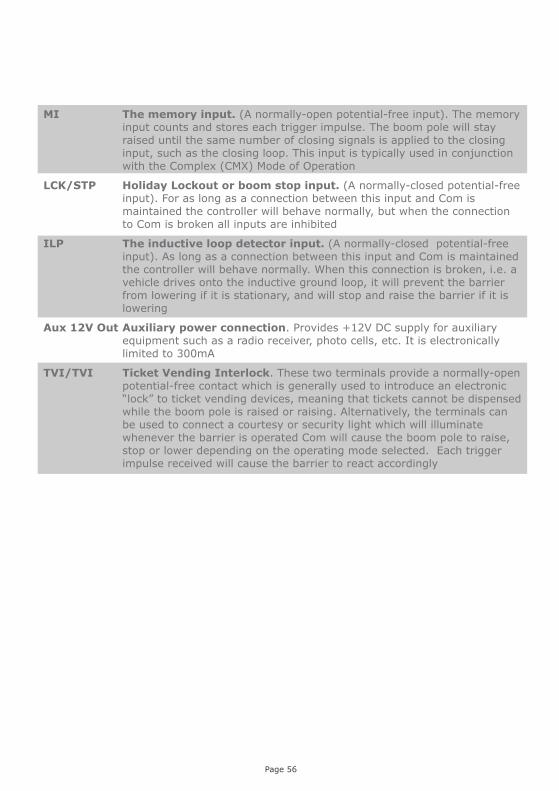
MI The memory input. (A normally-open potential-free input). The memory input counts and stores each trigger impulse. The boom pole will stay raised until the same number of closing signals is applied to the closing input, such as the closing loop. This input is typically used in conjunction with the Complex (CMX) Mode of Operation
LCK/STP Holiday Lockout or boom stop input. (A normally-closed potential-free input). For as long as a connection between this input and Com is maintained the controller will behave normally, but when the connection to Com is broken all inputs are inhibited
ILP The inductive loop detector input. (A normally-closed potential-free input). As long as a connection between this input and Com is maintained the controller will behave normally. When this connection is broken, i.e. a vehicle drives onto the inductive ground loop, it will prevent the barrier from lowering if it is stationary, and will stop and raise the barrier if it is lowering
Aux 12V Out Auxiliary power connection. Provides +12V DC supply for auxiliary equipment such as a radio receiver, photo cells, etc. It is electronically limited to 300mA
TVI/TVI Ticket Vending Interlock. These two terminals provide a normally-open potential-free contact which is generally used to introduce an electronic “lock” to ticket vending devices, meaning that tickets cannot be dispensed while the boom pole is raised or raising. Alternatively, the terminals can be used to connect a courtesy or security light which will illuminate whenever the barrier is operated Com will cause the boom pole to raise, stop or lower depending on the operating mode selected. Each trigger impulse received will cause the barrier to react accordingly
Page 56

Page 57
Symptom Possible cause Solution
Barrier does not move
Blown fuse Battery low, faulty or
disconnected Latched input on
MI/NMI/Raise/Lower Incorrect spring tension
26. Faultfinders guide
Replace the 30A ATO fuse Refer to the battery charge level on
the diagnostic screen – replace if necessary. See Procedure A.
Ensure that there are no auto-activations set for these inputs that are still in effect. Refer to the matrix in the diagnostic screen showing auto-activations
The diagnostic screen will display how many turns is necessary to achieve optimum spring tension and in which direction the nut must be turned. When the ideal spring tension is reached, a zero will be displayed
Boom pole moves a short distance and stops
Battery low condition False collision condition Faulty or disconnected
DOSS Excessive play on the
gearbox Primary drive-arm is loose
on the output shaft
Check physical condition of battery and terminals; check battery charge state and charging voltage on diagnostic screen. See procedure A.
Ensure that nothing is hindering the trajectory of the boom pole
Replace faulty DOSS or reconnect unplugged DOSS connections
Tighten drive-arm or contact local CENTURION agent
Contact local CENTURION agent to service gearbox
Boom pole starts lowering, then abruptly stops and raises again
Collision sensitivity set too high
False collision condition
Adjust collision sensitivity to a MEDIUM or LOW setting
Check for physical obstructions
Controller cannot be set to Auto-lower, the Auto-lower status automatically reverts back to “Off”
Controller is set to “Complex” mode
Depending on the application, set the controller to “Simplex” mode
Procedure A - Low battery voltage condition
Status light flashes three times – LCD indicates battery lowIf the battery voltage is less than 13.5V DC, the barrier will not operate at all. For any other voltage, the battery could still be the cause of the problem. Is the battery being properly charged?

With the operator in manual mode, check the following and correct if necessary: That the boom pole can be easily raised or lowered by hand and does not stick or jam at
any stage That the spring tension is correct. A handy diagnostic screen, complete with graphic
representation, can be found by scrolling upwards. This will tell you exactly how many turns of the spring tensioner are needed and in which direction, be it clockwise or counter-clockwise
That there is not excessive play on the gearbox That the primary drive-arm is not loose on the output shaft Check the DC motor wires for any loose connections Ensure that the DOSS sensor wire harness is securely plugged into the controller Ensure that the DOSS sensor is securely clipped into the housing If the problem is not solved, replace the DOSS sensor and main controller
Page 58
Procedure B - False collision detectionStatus light flashes four times to indicate that number of collisions have exceeded the Collision Counter feature value. LCD screen indicates “Max Collisions”
Check the “Mains Present” icon on the main diagnostic screen or switch to the battery charger diagnostic screen and check the charging voltage – right hand voltage. This should indicate XV
Check that the mains power is turned on (check 220-240V AC on the mains connector) Check that the red LED on the side of the charger is lit Check the charger’s supply fuse Check that the white battery charger connector is making proper contact Check the condition of the battery leads, terminals and connectors. Look for and correct
all loose connections and signs of corrosion The battery might be discharged. Measure the battery voltage with the charger
connected, if the voltage is below 13.5V then the battery is discharged. The number of raising cycles per hour may be excessive, thus discharging the battery
The charger may be faulty. Disconnect the battery and measure the voltage on the battery leads. It must be between 13.6V and 13.8V. If not, replace the charger
The battery might be old, and might have to be replaced. If in doubt test as follows: Check that the battery is charged, by ensuring that the battery voltage is above 13.5V
with the charger connected. (If the battery is in a good condition it would probably pass the test without being fully charged) Disconnect the charger from the battery Remove the DC Motor leads from the DC Controller Apply the DC motor leads directly to the battery, while measuring the battery voltage If the problem is not solved replace the DOSS sensor and main controller

27. Ancillary equipment
A number of additional devices are available which can be interfaced with the SECTOR traffic barrier to increase security or otherwise enhance the installation.
SECTOR breakaway coupling
The SECTOR breakaway coupling is a handy boom coupling that minimises damage to the boom pole by causing it to swing away to the side if struck by a vehicle. The breakaway coupler incorporates a micro-switch which is connected to the emergency stop input, meaning that the SECTOR will be barred from operating the moment that the micro-switch is unclipped. This significantly reduces the chance of further damage to the barrier.
TRAPEX
TRAPEX is a barrier fence that can be fitted to the SECTOR barrier boom pole (3m and 4.5m poles only) to facilitate pedestrian access control. The fence consists of a series of vertical poles which not only cover the area beneath the boom pole but also extends past the boom pole, meaning that the boom cannot be skirted. A link arm assembly prevents the boom from being pushed aside.
SECTOR jack-knife assembly
Some installations may require – due to a particularly low ceiling or similar hindrance which has diminished overhead space as a consequence – that the boom pole bend at an angle to allow for sufficient clearance when raising. A jack-knife assembly can be fitted to an existing boom pole which will allow the boom bole to bend at an angle by means of a metallic “knuckle”, and to become level again when in the lowered position.
Page 59
FIGURE 41. BREAKAWAY COUPLING
FIGURE 42. JACK-NIFE ASSEMBLY
FIGURE 43. TRAPEX
FIGURE 44. SECTOR fan
SECTOR fan
This kit – which consists of a 12V DC fan and sturdy mounting bracket – is highly effective in combating condensation in the barrier housing. The bracket connects effortlessly to the gearbox assembly and the fan can be powered using the barrier’s existing supply, so there is no need for any additional equipment.

CLAWS
CLAWS are modular barrier spikes designed to significantly enhance the security of an entry or exit. The CLAWS can be interfaced with the SECTOR traffic barrier in a direct drive configuration via the barrier’s external status output, i.e. the spikes will raise when the boom pole lowers etc. An independent drive configuration is also available, meaning that the CLAWS will operate independently from the co-installed SECTOR barrier. Also note that flush and surface mount variants of CLAWS are available.
CLAWS are highly effective in cases where optimum security and access control are required.
FLUX 11
In addition to the onboard inductive vehicle loop detector that is supplied with the SECTOR controller, a stand-alone 11 pin detector can also be installed to add an extra level of safety to any installation. The FLUX 11 is a single-channel, stand-alone highly sensitive inductive loop detector designed for vehicle access applications. The unit can be integrated into an existing SECTOR installation by plugging it into one of the 11 pin connectors, and used in conjunction with either a closing (safety) loop or a free-exit loop.
For more information on the SECTOR breakaway coupler, TRAPEX, CLAWS, FLUX 11 or any other CENTURION-supported products, please refer to the documentation included with the respective products or contact Centurion Systems directly.
Page 60
FIGURE 45. SURFACE AND FLUSH 3MOUNT CLAWS
FIGURE 46. FLUX 11
Midi Traffic Light
The CENTURION Midi Traffic Light enables you to visually indicate when it is safe for a vehicle to proceed into or out of an access controlled area, allowing for an added element of safety and control
FIGURE 47. Midi Traffic Light

Page 61
28. Installation handover
Once the installation has been successfully completed and tested, it is important for the installer to explain the operation and safety requirements of the system.
NEVER ASSUME THE USER KNOWS HOW TO SAFELY OPERATE AN AUTOMATED BARRIER!
Even if the user has used one before, it does not mean he knows how to SAFELY operate it. Make sure that the user fully understands the following safety requirements before finally handing over the site.
The following needs to be understood by the user: How to operate the manual release mechanism. (Show them how by
demonstration) How the safety loops and all other safety features work. (Show them how by
demonstration) All the features and benefits of the operator, i.e. Safety loops, etc. All the safety considerations associated with operating an automated barrier.
The user should be able to pass this knowledge on to all other users of the automated system and must be made aware of this responsibility.
Do not activate the barrier unless you can see it and can determine that its area of travel is clear of people, pets, or other obstructions
NO ONE MAY GO UNDER A MOVING BARRIER. Always keep people and objects away from the barrier
NEVER LET CHILDREN OPERATE OR PLAY WITH THE BARRIER CONTROLS, and do not allow children or pets near the barrier area
Be careful with moving parts and avoid close proximity to areas where fingers or hands could be pinched
Secure all easily accessed barrier operator controls in order to prevent its unauthorized use
Keep the automated barrier system properly maintained, and ensure that all working areas are free of d objects that could affect the its operation and safety
On a monthly basis, check the obstruction detection system and safety devices for correct operation
All repair and service work to this product must be done by a suitably qualified person
This product was designed and built strictly for the use indicated in this documentation. Any other use, not expressly indicated here, could compromise the good condition/operation of the product and/or be a source of danger!
Centurion Systems (Pty) Ltd does not accept any liability caused by improper use, of the product, or for use other than that for which the automated system was designed.
Ensure that the customer is in possession of the User Guide and that you have completed the installation details in the back of the manual.

Notes

Notes

0.07.A.0018_23072013
www.centsys.com
Sharecall 0860-CENTURION (0860 236 887)Head Office: +27 11 699 2400
Sharecall Technical Support 0861 003 123 or +27 11 699 2481from 07h00 to 18h00 (GMT+2)
(Sharecall numbers applicable when dialed from within South Africa only)