section v. special conditions of contract -...
TRANSCRIPT

71
Section V. Special Conditions of Contract

72
Special Conditions of Contract
GCC Clause
1.16 The Intended Completion Date is Two Hundred Forty (240)
calendar days.
1.21 The Procuring Entity is the Department of Transportation and
Communications (DOTC).
1.22 The Procuring Entity’s Representative is the DOTC Project Manager
concerned.
1.23 The Site is located at Brgy. Burgos, Daram, Samar.
1.27 The Start Date is the 7th
calendar day after the date of the receipt of
the Notice to Proceed.
1.30 The Works consist of Widening of Existing Causeway and
Construction of Wharf.
2.2 No further instructions.
5.1 The DOTC shall give possession of all parts of the Site to the
Contractor beginning on the date of effectivity of contract until the date
of its termination and/or project completion.
6.5 The Contractor shall employ the following Key Personnel:
Project Manager
Civil Engineer (licensed)
1 Materials Engineer (accredited by DPWH)
1 Safety Officer
7.4(c) No further instructions.
7.7 No further instructions.
8.1 No further instructions.
10 The site investigation reports are: Not Applicable.
12.3 No further instructions.
12.5 In case of permanent structures, such as buildings of types 4 and 5 as
classified under the National Building Code of the Philippines and other
structures made of steel, iron, or concrete which comply with relevant
structural codes (e.g., DPWH Standard Specifications), such as, but not
limited to, steel/concrete bridges, flyovers, aircraft movement areas,
ports, dams, tunnels, filtration and treatment plants, sewerage systems,
power plants, transmission and communication towers, railway system,
73
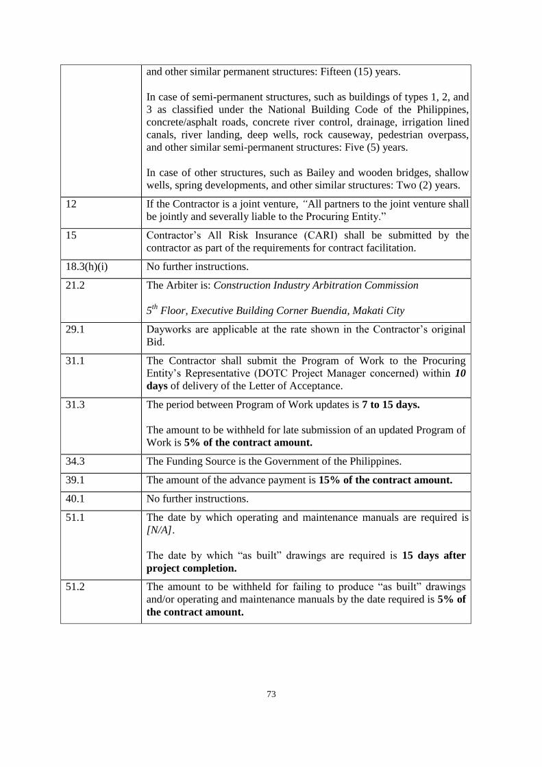
and other similar permanent structures: Fifteen (15) years.
In case of semi-permanent structures, such as buildings of types 1, 2, and
3 as classified under the National Building Code of the Philippines,
concrete/asphalt roads, concrete river control, drainage, irrigation lined
canals, river landing, deep wells, rock causeway, pedestrian overpass,
and other similar semi-permanent structures: Five (5) years.
In case of other structures, such as Bailey and wooden bridges, shallow
wells, spring developments, and other similar structures: Two (2) years.
12 If the Contractor is a joint venture, “All partners to the joint venture shall
be jointly and severally liable to the Procuring Entity.”
15 Contractor’s All Risk Insurance (CARI) shall be submitted by the
contractor as part of the requirements for contract facilitation.
18.3(h)(i) No further instructions.
21.2 The Arbiter is: Construction Industry Arbitration Commission
5th
Floor, Executive Building Corner Buendia, Makati City
29.1 Dayworks are applicable at the rate shown in the Contractor’s original
Bid.
31.1 The Contractor shall submit the Program of Work to the Procuring
Entity’s Representative (DOTC Project Manager concerned) within 10
days of delivery of the Letter of Acceptance.
31.3 The period between Program of Work updates is 7 to 15 days.
The amount to be withheld for late submission of an updated Program of
Work is 5% of the contract amount.
34.3 The Funding Source is the Government of the Philippines.
39.1 The amount of the advance payment is 15% of the contract amount.
40.1 No further instructions.
51.1 The date by which operating and maintenance manuals are required is
[N/A].
The date by which “as built” drawings are required is 15 days after
project completion.
51.2 The amount to be withheld for failing to produce “as built” drawings
and/or operating and maintenance manuals by the date required is 5% of
the contract amount.

74
Section VI. Specifications

75
Name of Project : CONSTRUCTION OF BRGY. BURGOS WHARF Location : Brgy. Burgos, Daram, Samar Duration : Two Hundred Forty (240) Calendar Days Source of Fund : C.Y. 2014
SCOPE OF WORK
The project covers the construction of causeway, back-up area from Sta. 0+029 to Sta. 0+037 and widening of wharf, which shall be done in accordance with the approved plans, specifications and provisions of contract under the following scope of works, to wit; 201 Aggregate Base Course. This item covers the supply of materials, labor and equipment
necessary in the laying of 0.30m. thick aggregate base course and should be spread and compacted prior to the pouring of Portland Cement Concrete Pavement. (Please refer to plans).
311 Portland Cement Concrete Pavement. This item covers the supply of materials, labor
and equipment required to construct the 0.15m thick concrete pavement along the proposed sea-landing with design strength for concrete of fc'= 3,500psi, all in accordance with the approved design grade, dimensions and cross-section. This is also include the supply and installation of all reinforcing steel bars required in paving joints as called for in the approved plans and specifications, and all formwork requirements. (Please refer to plans).
405 Concrete Works. This item covers the supply of materials, labor and equipment
necessary for the construction of footing, concrete facing, curb and stair with a minimum concrete strength of 3,500psi. All works shall be done in accordance with the approved plans and specifications. Provision of reinforcing steel bars and formworks shall also be included under this item. This item also includes the supply and installation of six (6) pieces stainless steel mooring cleat and its accessories. All shall be done in accordance with approved plans and specifications. (Please refer to plans)
511 Gabions (1.0 x 2.0 x 0.50m.). This item covers the supply of materials, labor and
equipment necessary for the formation of 1.0 x 2.0 x 0.50 meter Gabions, in accordance with the approved plans and design grade. (Please refer to plans)
508 Class III Rocks (For Gabions). This item covers the supply of labor, materials and equipment necessary for the formation of 5 to 15 kgs./pc Class III Rocks on a 1.0 x 2.0 x 0.50 gabions. This item shall be done as indicated and in accordance with the approved plans and specifications. (Pls. refer to plans)
SPL-1 Temporary Facilities.
The contractor shall supply the following provisions within ten (10) calendar days upon receipt of the Notice to Proceed (NTP).
A. DOTC Staff House
This includes the rental of a fully furnished staff house for the exclusive use of the Project Engineer. Payment of water and electric bill shall be the responsibility of contractor for the entire duration of the project.

76
B. Service Vehicle This covers the provision of service vehicle of at least 2009 model pick-up, air-con, in good running condition and updated registration, owned or leased, including driver and twelve (12) liters of fuel per day for the exclusive use of the DOTC Engineer supervising the project for the period of fifteen (15) calendar days. Maintenance and fuel cost for the service vehicle shall be included under this item.
This also covers the provision of at least 7-hp Motorized Boat, in good running condition
and on a rental basis including driver and twelve (12) liters of fuel per day for the exclusive use of the DOTC Engineer supervising the project for fifteen (15) Calendar Days.
The contractor shall be responsible for all laboratory, material testing and survey instruments necessary in the project implementation. Expenses for the said testing shall be incorporated in the contractor’s overhead cost and shall not be considered as pay item.

77
ITEM 201 – AGGREGATE BASE COURSE
201.1 Description This Item shall consist of furnishing, placing and compacting an aggregate base course on a prepared subgrade/subbase in accordance with this Specificaton and the lines, grades, thickness and typical cross-sections shown on the Plans, or as established by the Engineer.
201.2 Material Requirements Aggregate for base course shall consist of hard, durable particles or fragments of crushed stone, crushed slag or crushed or natural gravel and filler of natural or crushed sand or other finely divided mineral matter. The composite material shall be free from vegetable matter and lumps or balls of clay, and shall be of such nature that it can be compacted readily to form a firm, stable base. In some areas where the conventional base course materials are scarce or non-available, the use of 40% weathered limestone blended with 60% crushed stones or gravel shall be allowed, provided that the blended materials meet the requirements of this Item. The base course material shall conform to Table 201.1, whichever is called for in the Bill of Quantities
Table 201.1 – Grading Requirements
Sieve Designation Mass Percent Passing
Standard, mm
Alternate US Standard
Grading A Grading B
50 2” 100
37.5 1-1/2” - 100
25.0 1” 60 – 85 -
19.0 ¾” - 60 – 85
12.5 ½” 35 – 65 -
4.75 No. 4 20 – 50 30 – 55
0.425 No. 40 5 – 20 8 – 25
0.075 No. 200 0 – 12 2 – 14
The fraction passing the 0.075 mm (No. 200) sieve shall not be greater than 0.66 (two thirds) of the fraction passing the 0.425 mm (No. 40) sieve. The fraction passing the 0.425 mm (No. 40) sieve shall have a liquid limit not greater than 25 and plasticity index not greater than 6 as determined by AASHTO T 89 and T 90, respectively. The coarse portion, retained on a 2.00 mm (No. 10) sieve shall have a mass percent of wear not exceeding 50 by the Los Angeles Abrasion test determined by AASHTO T 96. The material passing the 19 mm (3/4 inch) sieve shall have a soaked CBR value of not less than 80% as determined by AASHTO T 193. The CBR value shall be obtained at the maximum dry density (MDD) as determined by AASHTO T 180, Method D.

78
If filler, in addition to that naturally present, is necessary for meeting the grading requirements or for satisfactory bonding, it shall be uniformly blended with the base course material on the road or in a pugmill unless otherwise specified or approved. Filler shall be taken from sources approved by the Engineer, shall be free from hard lumps and shall not contain more than 15 percent of material retained on the 4.75 mm (No. 4) sieve.
201.3 Construction Requirements 201.3.1 Preparation of Existing Surface
The existing surface shall be graded and finished as provided under Item 105, Subgrade Preparation, before placing the base material. 201.3.2 Placing It shall be in accordance with all the requirements of Subsection 200.3.2, Placing.
201.3.3 Spreading and Compacting It shall be in accordance with all the requirements of Subsection 200.3.3, Spreading and Compacting. 201.3.4 Trial Sections Trial sections shall conform in all respects to the requirements specified in Subsection 200.3.4. 201.3.5 Tolerances The aggregate base course shall be laid to the designed level and transverse slopes shown on the Plans. The allowable tolerances shall be in accordance with following:
Permitted variation from design THICKNESS OF LAYER
± 10 mm
Permitted variation from design LEVEL OF SURFACE
+ 5 mm -10 mm
Permitted SURFACE IRREGULARITY Measured by 3-m straight-edge
5 mm
Permitted variation from design CROSSFALL OR CAMBER
± 0.2%
Permitted variation from design LONGITUDINAL GRADE over 25 m in length
± 0.1%
201.4 Method of Measurement Aggregate Base Course will be measured by the cubic meter (m3). The quantity to be paid for shall be the design volume compacted in-place as shown on the Plans, and accepted in the

79
completed base course. No allowance shall be given for materials placed outside the design limits shown on the cross-sections. Trial sections shall not be measured separately but shall be included in the quantity of aggregate base course. 201.5 Basis of Payment The accepted quantities, measured as prescribed in Section 201.4, shall be paid for at the contract unit price for Aggregate Base Course which price and payment shall be full compensation for furnishing and placing all materials, including all labor, equipment, tools and incidentals necessary to complete the work prescribed in this Item. Payment will be made under:
Pay Item Number Description Unit of Measurement
201 Aggregate Base Course Cubic Meter

80
ITEM 311 – PORTLAND CEMENT CONCRETE PAVEMENT
311.1 Description This Item shall consist of pavement of Portland Cement Concrete, with or without
reinforcement, constructed on the prepared base in accordance with this Specification and in conformity with lines, grades, thickness and typical cross-section shown on the Plans.
311.2 Material Requirements
311.2.1 Portland Cement
It shall conform to the applicable requirements of Item 700, Hydraulic Cement. Only Type I
Portland Cement shall be used unless otherwise provided for in the Special Provisions. Different brands or the same brands from different mills shall not be mixed nor shall they be used alternately unless the mix is approved by the Engineer. However, the use of Portland Pozzolan Cement Type IP meeting the requirements of AASHTO M 240/ASTM C 695, Specifications for Blended Hydraulic Cement shall be allowed, provided that trial mixes shall be done and that the mixes meet the concrete strength requirements, the AASHTO/ASTM provisions pertinent to the use of Portland Pozzolan Type IP shall be adopted.
Cement which for any reason has become partially set or which contains lumps of caked
cement will be rejected. Cement salvaged from discarded or used bags shall not be used. Samples of Cement shall be obtained in accordance with AASHTO T 127.
311.2.2 Fine Aggregate
It shall consist of natural sand, stone screenings or other inert materials with similar
characteristics, or combinations thereof, having hard, strong and durable particles. Fine aggregate from different sources of supply shall not be mixed or stored in the same pile nor used alternately in the same class of concrete without the approval of the Engineer.
It shall not contain more than three (3) mass percent of material passing the 0.075 mm (No.
200 sieve) by washing nor more than one (1) mass percent each of clay lumps or shale. The use of beach sand will not be allowed without the approval of the Engineer.
If the fine aggregate is subjected to five (5) cycles of the sodium sulfate soundness test, the
weighted loss shall not exceed 10 mass percent.
The fine aggregate shall be free from injurious amounts of organic impurities. If subjected to the colorimatic test for organic impurities and a color darker than the standard is produced, it shall be rejected. However, when tested for the effect of organic impurities of strength of mortar by AASHTO T 71, the fine aggregate may be used if the relative strength at 7 and 28 days is not less than 95 mass percent.

81
The fine aggregate shall be well-graded from course to fine and shall conform to Table 311.1
Table 311.1 – Grading Requirements for Fine Aggregate
Sieve Designation Mass Percent Passing
9.5 mm (3/8 in) 100
4.75 mm (No. 4) 95 – 100
2.36 mm (No. 8) -
1.18 mm (No. 16) 45 – 80
0.600 mm (No. 30)
-
0.300 mm (No. 50)
5 – 30
0.150 mm (No. 100)
0 – 10
311.2.3 Coarse Aggregate
It shall consist of crushed stone, gravel, blast furnace slag, or other approved inert materials
of similar characteristics, or combinations thereof, having hard, strong, durable pieces and free from any adherent coatings.
It shall contain not more than one (1) mass percent of material passing the 0.075 mm (No.
200) sieve, not more than 0.25 mass percent of clay lumps, nor more than 3.5 mass percent of soft fragments.
If the coarse aggregate is subjected to five (5) cycles of the sodium sulfate soundness test,
the weighted loss shall not exceed 12 mass percent.
It shall have a mass percent of wear not exceeding 40 when tested by AASHTO T 96. If the slag is used, its density shall not be less than 1120 kg/m3 (70 lb./cu. ft.). The gradation
of the coarse aggregate shall conform to Table 311.2.
Only one grading specification shall be used from any one source.
Table 311.2 – Grading Requirement for Coarse Aggregate
Sieve Designation Mass Percent Passing
Standard Mm
Alternate U. S.
Standard
Grading A
Grading B
Grading C
75.00 3 in. 100 - -
63.00 2-1/2 in. 90-100 100 100
50.00 2 in. - 90-100 95-100
37.5 1-1/2 in. 25-60 35-70 -

82
25.0 1 in. - 0-15 35-70
19.0 ¾ in. 0-10 - -
12.5 ½ in. 0-5 0-5 10-30
4.75 No. 4 - - 0-5
311.2.4 Water Water used in mixing, curing or other designated application shall be reasonably clean and free of oil, salt, acid, alkali, grass or other substances injurious to the finished product. Water will be tested in accordance with and shall meet the requirements of Item 714, Water. Water which is drinkable may be used without test. Where the source of water is shallow, the intake shall be so enclosed as to exclude silt, mud, grass or other foreign materials. 311.2.5 Reinforcing Steel It shall conform to the requirements of Item 404, Reinforcing Steel. Dowels and tie bars shall conform to the requirements of AASHTO M 31 or M 42, except that rail steel shall not be used for tie bars that are to be bent and restraightened during construction. Tie bars shall be deformed bars. Dowels shall be plain round bars. Before delivery to the site of work, one-half of the length of each dowel shall be painted with one coat of approved lead or tar paint. The sleeves for dowel bars shall be metal of approved design to cover 50 mm ( 2 inches), plus or minus 5 mm (1/4 inch) of the dowel, with a closed end, and with a suitable stop to hold the end of the sleeve at least 25 mm (1 inch) from the end of the dowel. Sleeves shall be of such design that they do not collapse during construction. 311.2.6 Joint Fillers
Poured joint fillers shall be mixed asphalt and mineral or rubber filler conforming to the
applicable requirements of Item 705, Joint Materials. Preformed joint filler shall conform to the applicable requirements of Item 705. It shall be
punched to admit the dowels where called for in the Plans. The filler for each joint shall be furnished in a single piece for the full depth and width required for the joint.
311.2.7 Admixtures
Air-entraining admixture shall conform to the requirements of AASHTO M 154. Chemical admixtures, if specified or permitted, shall conform to the requirements of
AASHTO M 194.
Fly Ash, if specified or permitted as a mineral admixture and as 20% partial replacement of Portland Cement in concrete mix shall conform to the requirements of ASTM C 618.
Admixture should be added only to the concrete mix to produce some desired modifications to the properties of concrete where necessary, but not as partial replacement of cement.

83
311.2.8 Curing Materials Curing materials shall conform to the following requirements as specified;
a) Burlap cloth - AASHTO M 182 b) Liquid membrane forming compounds
- AASHTO M 148
c) Sheeting (film) materials - AASHTO M 171 Cotton mats and water-proof paper can be used. 311.2.9 Calcium Chloride/Calcium Nitrate
It shall conform to AASHTO M 144, if specified or permitted by the Engineer, as accelerator.
311.2.10 Storage of Cement and Aggregate
All cement shall be stored, immediately upon delivery at the Site, in weatherproof building which will protect the cement from dampness. The floor shall be raised from the ground. The buildings shall be placed in locations approved by the Engineer. Provisions for storage shall be ample, and the shipments of cement as received shall be separately stored in such a manner as to allow the earliest deliveries to be used first and to provide easy access for identification and inspection of each shipment. Storage buildings shall have capacity for storage of a sufficient quantity of cement to allow sampling at least twelve (12) days before the cement is to be used. Bulk cement, if used, shall be transferred to elevated air tight and weatherproof bins. Stored cement shall meet the test requirements at any time after storage when retest is ordered by the Engineer. At the time of use, all cement shall be free-flowing and free of lumps.
The handling and storing of concrete aggregates shall be such as to prevent segregation or the inclusion of foreign materials. The Engineer may require that aggregates be stored on separate platforms at satisfactory locations.
In order to secure greater uniformity of concrete mix, the Engineer may require that the coarse aggregate be separated into two or more sizes. Different sizes of aggregate shall be stored in separate bins or in separate stockpiles sufficiently removed from each other to prevent the material at the edges of the piles from becoming intermixed. 311.2.11 Proportioning, Consistency and Strength of Concrete
The Contractor shall prepare the design mix based on the absolute volume method as outlined in the American Concrete Institute (ACI) Standard 211.1, “Recommended Practice for Selecting Proportions for Normal and Heavyweight Concrete”. It is the intent of this Specification to require at least 364 kg of cement per cubic meter of concrete to meet the minimum strength requirements. The Engineer shall determine from laboratory tests of the materials to be used, the cement content and the proportions of aggregate and water that will produce workable concrete having a slump of between 40 and 75 mm (1-1/2 and 3 inches) if not vibrated or between 10 and 40 mm (1/2 and 1-1/2 inches) if vibrated, and a flexural strength of not less than 3.8 MPa (550 psi) when tested by the third-point method or 4.5 MPa (650 psi) when tested by the mid-point method at fourteen (14) days

84
in accordance with AASHTO T97 and T177, respectively; or a compressive strength of 24.1 MPa (3500 psi) for cores taken at fourteen (14) days and tested in accordance with AASHTO T24. Slump shall be determined using AASHTO T 119. The designer shall consider the use of lean concrete (econocrete) mixtures using local materials or specifically modified conventional concrete mixes in base course and in the lower course composite, monolithic concrete pavements using a minimum of 75 mm (3 inches) of conventional concrete as the surface course. The mix design shall be submitted to the Engineer for approval and shall be accompanied with certified test data from an approved laboratory demonstrating the adequacy of the mix design. A change in the source of materials during the progress of work may necessitate a new design mix.
311.3 Construction Requirements 311.3.1 Quality Control of Concrete
1. General
The Contractor shall be responsible for the quality control of all materials during the handling, blending, and mixing and placement operations.
2. Quality Control Plan
The Contractor shall furnish the Engineer a Quality Control Plan detailing his production control procedures and the type and frequency of sampling and testing to insure that the concrete produces complies with the Specifications. The Engineer shall be provided free access to recent plant production records, and if requested, informational copies of mix design, materials certifications and sampling and testing reports.
3. Qualification of Workmen
Experienced and qualified personnel shall perform all batching or mixing operation for the concrete mix, and shall be present at the plant and job site to control the concrete productions whenever the plant is in operation. They shall be identified and duties defined as follows: a. Concrete Batcher. The person performing the batching or mixing operation
shall be capable of accurately conducting aggregate surface moisture determination and establishing correct scale weights for concrete materials. He shall be capable of assuring that the proportioned batch weights of materials are in accordance with the mix design.
b. Concrete Technician. The person responsible for concrete production control
and sampling and testing for quality control shall be proficient in concrete technology and shall have a sound knowledge of the Specifications as they relate to concrete production. He shall be capable of conducting tests on concrete

85
and concrete materials in accordance with these Specifications. He shall be capable of adjusting concrete mix designs for improving workability and Specification compliance and preparing trial mix designs. He shall be qualified to act as the concrete batcher in the batcher’s absence.
4. Quality Control Testing
The Contractor shall perform all sampling, testing and inspection necessary to assure quality control of the component materials and the concrete. The Contractor shall be responsible for determining the gradation of fine and coarse aggregates and for testing the concrete mixture for slump, air content, water-cement ratio and temperature. He shall conduct his operations so as to produce a mix conforming to the approved mix design.
5. Documentation
The Contractor shall maintain adequate records of all inspections and tests. The records shall indicate the nature and number of observations made, the number and type of deficiencies found, the quantities approved and rejected, and nature of any corrective action taken.
The Engineer may take independent assurance samples at random location for acceptance purposes as he deems necessary.
311.3.2 Equipment
Equipment and tools necessary for handling materials and performing all parts of the work shall be approved by the Engineer as to design, capacity and mechanical condition. The equipment shall be at the jobsite sufficiently ahead of the start of construction operations to be examined thoroughly and approved.
1. Batching Plant and Equipment
a. General. The batching shall include bins, weighing hoppers, and scales for the fine aggregate and for each size of coarse aggregate. If cement is used in bulk, a bin, a hopper, and separate scale for cement shall be included. The weighing hopper shall be properly sealed and vented to preclude dusting operation. The batch plant shall be equipped with a suitable non-resettable batch counter which will correctly indicate the number of batches proportioned.
b. Bins and Hoppers. Bins with adequate separate compartments for fine
aggregate and for each size of coarse aggregate shall be provided in the batching plant.
c. Scales. Scales for weighing aggregates and cement shall be of either the beam
type or the springless-dial type. They shall be accurate within one-half percent (0.5%) throughout the range of use. Poises shall be designed to be locked in any position and to prevent unauthorized change.

86
Scales shall be inspected and sealed as often as the Engineer may deem necessary to assure their continued accuracy.
d. Automatic Weighing Devices. Unless otherwise allowed on the Contract, batching
plants shall be equipped with automatic weighing devices of an approved type to proportion aggregates and bulk cement.
2. Mixers.
a. General. Concrete may be mixed at the Site of construction or at a central plant,
or wholly or in part in truck mixers. Each mixer shall have a manufacturer’s plate attached in a prominent place showing the capacity of the drum in terms of volume of mixed concrete and the speed of rotation of the mixing drum or blades.
b. Mixers at Site of Construction. Mixing shall be done in an approved mixer
capable of combining the aggregates, cement and water into a thoroughly mixed and uniform mass within the specified mixing period and discharging and distributing the mixture without segregation on the prepared grade. The mixer shall be equipped with an approved timing device which will automatically lock the discharge lever when the drum has been charged and released it at the end of the mixing period. In case of failure of the timing device, the mixer may be used for the balance of the day while it is being repaired, provided that each batch is mixed 90 seconds. The mixer shall be equipped with a suitable nonresettable batch counter which shall correctly indicate the number of the batches mixed.
c. Truck Mixer and Truck Agitators. Truck mixers used for mixing and hauling
concrete, and truck agitators used for hauling central-mixed concrete, shall conform to the requirements of AASHTO M 157.
d. Non-Agitator Truck. Bodies of non-agitating hauling equipment for concrete
shall be smooth, mortar-tight metal containers and shall be capable of discharging the concrete at a satisfactory controlled rate without segregation.
3. Paving and Finishing Equipment
The concrete shall be placed with an approved paver designed to spread, consolidate, screed and float finish the freshly placed concrete in one complete pass of the machine in such a manner that a minimum of hand finishing will be necessary to provide a dense and homogeneous pavement in conformance with the Plans and Specifications. The finishing machine shall be equipped with at least two (2) oscillating type transverse screed. Vibrators shall operate at a frequency of 8,300 to 9,600 impulses per minute under load at a maximum spacing of 60 cm.
4. Concrete Saw

87
The Contractor shall provide sawing equipment in adequate number of units and power to complete the sawing with a water-cooled diamond edge saw blade or an abrasive wheel to the required dimensions and at the required rate. He shall provide at least one (1) stand-by saw in good working condition and with an ample supply of saw blades.
5. Forms
Forms shall be of steel, of an approved section, and of depth equal to the thickness of the pavement at the edge. The base of the forms shall be of sufficient width to provide necessary stability in all directions. The flange braces must extend outward on the base to not less than 2/3 the height of the form. All forms shall be rigidly supported on bed of thoroughly compacted material during the entire operation of placing and finishing the concrete. Forms shall be provided with adequate devices for secure setting so that when in place, they will withstand, without visible spring or settlement, the impact and vibration of the consolidation and finishing or paving equipment.
311.3.3 Preparation of Grade
After the subgrade of base has been placed and compacted to the required density, the areas which will support the paving machine and the grade on which the pavement is to be constructed shall be trimmed to the proper elevation by means of a properly designed machine extending the prepared work areas compacted at least 60 cm beyond each edge of the proposed concrete pavement. If loss of density results from the trimming operations, it shall be restored by additional compaction before concrete is placed. If any traffic is allowed to use the prepared subgrade or base, the surface shall be checked and corrected immediately ahead of the placing concrete.
The subgrade or base shall be uniformly moist when the concrete is placed.
311.3.4 Setting Forms
1. Base Support.
The foundation under the forms shall be hard and true to grade so that the form when set will be firmly in contact for its whole length and at the specified grade. (Any roadbed, which at the form line is found below established grade, shall be filled with approved granular materials to grade in lifts of three (3) cm or less, and thoroughly rerolled or tamped.) Imperfections or variations above grade shall be corrected by tamping or by cutting as necessary.
2. Form Setting
Forms shall be set sufficiently in advance of the point where concrete is being placed. After the forms have been set to correct grade, the grade shall be thoroughly tamped, mechanically or by hand, at both the inside and outside edges of the base of

88
the forms. The forms shall not deviate from true line bv more than one (1) cm at any point.
3. Grade and Alignment
The alignment and grade elevations of the forms shall be checked and corrections made by the Contractor immediately before placing the concrete. Testing as to crown and elevation, prior to placing of concrete can be made by means of holding an approved template in a vertical position and moved backward and forward on the forms. When any form has been disturbed or any grade has become unstable, the form shall be reset and rechecked.
311.3.5 Conditioning of Subgrade or Base Course
When side forms have been securely set to grade, the subgrade or base course shall be brought to proper cross-section. High areas shall be trimmed to proper elevation. Low areas shall be filled and compacted to a condition similar to that of surrounding grade. The finished grade shall be maintained in a smooth and compacted condition until the pavement is placed.
Unless waterproof subgrade or base course cover material is specified, the subgrade or base
course shall be uniformly moist when the concrete is placed. If it subsequently becomes too dry, the subgrade or base course shall be sprinkled, but the method of sprinkling shall not be such as to form mud or pools of water.
311.3.6 Handling, Measuring and Batching Materials
The batch plant site, layout, equipment and provisions for transporting material shall be such as to assure a continuous supply of material to the work. Stockpiles shall be built up in layers of not more than one (1) meter in thickness. Each layer shall be completely in place before beginning the next which shall not be allowed to “cone” down over the next lower layer. Aggregates from different sources and of different grading shall not be stockpiled together. All washed aggregates and aggregates produced or handled by hydraulic methods, shall be stockpiled or binned for draining at least twelve (12) hours before being batched. When mixing is done at the side of the work, aggregates shall be transported from the batching plant to the mixer in batch boxes, vehicle bodies, or other containers of adequate capacity and construction to properly carry the volume required. Partitions separating batches shall be adequate and effective to prevent spilling from one compartment to another while in transit or being dumped. When bulk cement is used, the Contractor shall use a suitable method of handling the cement from weighing hopper to transporting container or into the batch itself for transportation to the mixer, with chute, boot or other approved device, to prevent loss of cement, and to provide positive assurance of the actual presence in each batch of the entire cement content specified.

89
Bulk cement shall be transported to the mixer in tight compartments carrying the full amount of cement required for the batch. However, if allowed in the Special Provisions, it may be transported between the fine and coarse aggregate. When cement is placed in contact with the aggregates, batches may be rejected unless mixed within 1-1/2 hours of such contact. Cement in original shipping packages may be transported on top of the aggregates, each batch containing the number of sacks required by the job mix. The mixer shall be charged without loss of cement. Batching shall be so conducted as to result in the weight to each material required within a tolerance of one (1) percent for the cement and two (2) percent for aggregates. Water may be measured either by volume or by weight. The accuracy of measuring the water shall be within a range of error of not over than one (1) percent. Unless the water is to be weighed, the water-measuring equipment shall include an auxiliary tank from which the measuring tank shall be equipped with an outside tap and valve to provide checking the setting, unless other means are provided for readily and accurately determining the amount of water in the tank. The volume of the auxiliary tank shall be at least equal to that of the measuring tank.
311.3.7 Mixing Concrete
The concrete may be mixed at the site of the work in a central-mix plant, or in truck mixers. The mixer shall be of an approved type and capacity. Mixing time will be measured from the time all materials, except water, are in the drum. Ready-mixed concrete shall be mixed and delivered in accordance with requirements of AASHTO M 157, except that the minimum required revolutions at the mixing speed for transit-mixed concrete may be reduced to not less than that recommended by the mixer manufacturer. The number of revolutions recommended by the mixer manufacturer shall be indicated on the manufacturer’s serial plate attached to the mixer. The Contractor shall furnish test data acceptable to the Engineer verifying that the make and model of the mixer will produce uniform concrete conforming to the provision of AASHTO M 157 at the reduced number of revolutions shown on the serial plate.
When mixed at the site or in a central mixing plant, the mixing time shall not be less than
fifty (50) seconds nor more than ninety (90) seconds, unless mixer performance tests prove adequate mixing of the concrete is a shorter time period.
Four (4) seconds shall be added to the specified mixing time if timing starts at the instant the
skip reaches its maximum raised positions. Mixing time ends when the discharge chute opens. Transfer time in multiple drum mixers is included in mixing time. The contents of an individual mixer drum shall be removed before a succeeding batch is emptied therein.
The mixer shall be operated at the drum speed as shown on the manufacturer’s name plate
attached on the mixer. Any concrete mixed less than the specified time shall be discarded and disposed off by the Contractor at his expense. The volume of concrete mixed per batch shall not exceed the mixer’s nominal capacity in cubic metre, as shown on the manufacturer’s standard rating plate on the mixer, except that an overload up to ten (10) percent above the mixer’s nominal capacity may be permitted provided concrete test data for strength, segregation, and uniform consistency are satisfactory, and provided no spillage of concrete takes place.
The batches shall be so charged into the drum that a portion of the mixing water shall be
entered in advance of the cement and aggregates. The flow of water shall be uniform and all water

90
shall be in the drum by the end of the first fifteen (15) seconds of the mixing period. The throat of the drum shall be kept free of such accumulations as may restrict the free flow of materials into the drum.
Mixed concrete from the central mixing plant shall be transported in truck mixers, truck
agitators or non-agitating truck specified in Subsection 311.3.2, Equipment. The time elapsed from the time water is added to the mix until the concrete is deposited in place at the Site shall not exceed forty five (45) minutes when the concrete is hauled in non-agitating trucks, nor ninety (90) minutes when hauled in truck mixers or truck agitators, except that in hot weather or under other conditions contributing to quick hardening of the concrete, the maximum allowable time may be reduced by the Engineer.
In exceptional cases and when volumetric measurements are authorized for small project
requiring less than 75 cu.m. of concrete per day of pouring, the weight proportions shall be converted to equivalent volumetric proportions. In such cases, suitable allowance shall be made for variations in the moisture condition of the aggregates, including the bulking effect in the fine aggregate. Batching and mixing shall be in accordance with ASTM C 685, Section 6 through 9.
Concrete mixing by chute is allowed provided that a weighing scales for determining the batch weight will be used.
Retempering concrete by adding water or by other means shall not be permitted, except
that when concrete is delivered in truck mixers, additional water may be added to the batch materials and additional mixing performed to increase the slump to meet the specified requirements, if permitted by the Engineer, provided all these operations are performed within forty-five (45) minutes after the initial mixing operation and the water-cement ratio is not exceeded. Concrete that is not within the specified slump limits at the time of placement shall not be used. Admixtures for increasing the workability or for accelerating the setting of the concrete will be permitted only when specifically approved by the Engineer.
311.3.8 Limitation of Mixing
No concrete shall be mixed, placed or finished when natural light is insufficient, unless an adequate and approved artificial lighting system is operated. During hot weather, the Engineer shall require that steps be taken to prevent the temperature of mixed concrete from exceeding a maximum temperature of 900F ( 320C) Concrete not in place within ninety (90) minutes from the time the ingredients were charged into the mixing drum or that has developed initial set shall not be used. Retempering of concrete or mortar which has partially hardened, that is remixing with or without additional cement, aggregate, or water, shall not be permitted. In order that the concrete may be properly protected against the effects of rain before the concrete is sufficiently hardened, the Contractor will be required to have available at all times materials for the protection of the edges and surface of the unhardened concrete.

91
311.3.9 Placing Concrete
Concrete shall be deposited in such a manner to require minimal rehandling. Unless truck mixers or non-agitating hauling equipment are equipped with means to discharge concrete without segregation of the materials, the concrete shall be unloaded into an approved spreading device and mechanically spread on the grade in such a manner as to prevent segregation. Placing shall be continuous between transverse joints without the use of intermediate bulkheads. Necessary hand spreading shall be done with shovels, not rakes. Workmen shall not be allowed to walk in the freshly mixed concrete with boots or shoes coated with earth or foreign substances.
When concrete is to be placed adjoining a previously constructed lane and mechanical
equipment will be operated upon the existing lane, that previously constructed lane shall have attained the strength for fourteen (14) day concrete. If only finishing equipment is carried on the existing lane, paving in adjoining lanes may be permitted after three (3) days.
Concrete shall be thoroughly consolidated against and along the faces of all forms and along
the full length and on both sides of all joint assemblies, by means of vibrators inserted in the concrete. Vibrators shall not be permitted to come in contact with a joint assembly, the grade, or a side form. In no case shall the vibrator be operated longer than fifteen (15) seconds in any one location.
Concrete shall be deposited as near as possible to the expansion and contraction joints
without disturbing them, but shall not be dumped from the discharge bucket or hopper into a joint assembly unless the hopper is well centered on the joint assembly. Should any concrete material fall on or be worked into the surface of a complete slab, it shall be removed immediately.
311.3.10 Test Specimens
As work progresses, at least one (1) set consisting of three (3) concrete beam test specimens, 150 mm x 150 mm x 525 mm or 900 mm shall be taken from each 330 m2 of pavement, 230 mm depth, or fraction thereof placed each day. Test specimens shall be made under the supervision of the Engineer, and the Contractor shall provide all concrete and other facilities necessary in making the test specimens and shall protect them from damage by construction operations. Cylinder samples shall not be used as substitute for determining the adequacy of the strength of concrete. The beams shall be made, cured, and tested in accordance with AASHTO T 23 and T 97.
311.3.11 Strike-off of Concrete and Placement of Reinforcement Following the placing of the concrete, it shall be struck off to conform to the cross-section shown on the Plans and to an elevation such that when the concrete is properly consolidated and finished, the surface of the pavement will be at the elevation shown on the Plans. When reinforced concrete pavement is placed in two (2) layers, the bottom layer shall be struck off and consolidated to such length and depth that the sheet of fabric or bar mat may be laid full length on the concrete in its final position without further manipulation. The reinforcement shall then be placed directly upon the concrete, after which the top layer of the concrete shall be placed, struck off and screeded. Any portion of the bottom layer of concrete which has been placed more then 30 minutes without being covered with the top layer shall be removed and replaced with freshly mixed concrete at the Contractor’s expense. When reinforced concrete is placed in one layer, the reinforcement may be

92
firmly positioned in advance of concrete placement or it may be placed at the depth shown on the Plans in plastic concrete, after spreading by mechanical or vibratory means. Reinforcing steel shall be free from dirt, oil, paint, grease, mill scale and loose or thick rust which could impair bond of the steel with the concrete.
311.3.12 Joints
Joints shall be constructed of the type and dimensions, and at the locations required by the Plans or Special Provisions. All joints shall be protected from the intrusion of injurious foreign material until sealed.
1. Longitudinal Joint
Deformed steel tie bars of specified length, size, spacing and materials shall be placed perpendicular to the longitudinal joints, they shall be placed by approved mechanical equipment or rigidly secured by chair or other approved supports to prevent displacement. Tie bars shall not be painted or coated with asphalt or other materials or enclosed in tubes or sleeves. When shown on the Plans and when adjacent lanes of pavement are constructed separately, steel side forms shall be used which will form a keyway along the construction joint. Tie bars, except those made of rail steel, may be bent at right angles against the form of the first lane constructed and straightened into final position before the concrete of the adjacent lane is placed, or in lieu of bent tie bars, approved two-piece connectors may be used. Longitudinal formed joints shall consist of a groove or cleft, extending downward from and normal to, the surface of the pavement. These joints shall be effected or formed by an approved mechanically or manually operated device to the dimensions and line indicated on the Plans and while the concrete is in a plastic state. The groove or cleft shall be filled with either a premolded strip or poured material as required. The longitudinal joints shall be continuous, there shall be no gaps in either transverse or longitudinal joints at the intersection of the joints. Longitudinal sawed joints shall be cut by means of approved concrete saws to the depth, width and line shown on the Plans. Suitable guide lines or devices shall be used to assure cutting the longitudinal joint on the true line. The longitudinal joint shall be sawed before the end of the curing period or shortly thereafter and before any equipment or vehicles are allowed on the pavement. The sawed area shall be thoroughly cleaned and, if required, the joint shall immediately be filled with sealer. Longitudinal pavement insert type joints shall be formed by placing a continuous strip of plastic materials which will not react adversely with the chemical constituent of the concrete.
2. Transverse Expansion Joint
The expansion joint filler shall be continuous from form to form, shaped to subgrade and to the keyway along the form. Preformed joint filler shall be furnished in lengths equal to the pavement width or equal to the width of one lane. Damaged or repaired joint filler shall not be used.

93
The expansion joint filler shall be held in a vertical position. An approved installing bar, or other device, shall be used if required to secure preformed expansion joint filler at the proper grade and alignment during placing and finishing of the concrete. Finished joint shall not deviate more than 6 mm from a straight line. If joint fillers are assembled in sections, there shall be no offsets between adjacent units. No plugs of concrete shall be permitted anywhere within the expansion space.
3. Transverse Contraction Joint/Weakened Joint
When shown on the Plans, it shall consist of planes of weakness created by forming or cutting grooves in the surface of the pavement and shall include load transfer assemblies. The depth of the weakened plane joint should at all times not be less than 50 mm, while the width should not be more than 6 mm. a. Transverse Strip Contraction Joint. It shall be formed by installing a parting strip
to be left in place as shown on the Plans. b. Formed Groove. It shall be made by depressing an approved tool or device into
the plastic concrete. The tool or device shall remain in place at least until the concrete has attained its initial set and shall then be removed without disturbing the adjacent concrete, unless the device is designed to remain in the joint.
c. Sawed Contraction Joint. It shall be created by sawing grooves in the surface of
the pavement of the width not more than 6 mm, depth should at all times not be less than 50 mm, and at the spacing and lines shown on the Plans, with an approved concrete saw. After each joint is sawed, it shall be thoroughly cleaned including the adjacent concrete surface.
Sawing of the joint shall commence as soon as the concrete has hardened sufficiently to permit sawing without excessive ravelling, usually 4 to 24 hours. All joints shall be sawed before uncontrolled shrinkage cracking takes place. If necessary, the sawing operations shall be carried on during the day or night, regardless of weather conditions. The sawing of any joint shall be omitted if crack occurs at or near the joint location prior to the time of sawing. Sawing shall be discounted when a crack develops ahead of the saw. In general, all joints should be sawed in sequence. If extreme condition exist which make it impractical to prevent erratic cracking by early sawing, the contraction joint groove shall be formed prior to initial set of concrete as provided above.
4. Transverse Construction Joint
It shall be constructed when there is an interruption of more than 30 minutes in the concreting operations. No transverse joint shall be constructed within 1.50 m of an expansion joint, contraction joint, or plane of weakness. If sufficient concrete has been mixed at the time of interruption to form a slab of at least 1.5 m long, the excess concrete from the last preceding joint shall be removed and disposed off as directed.

94
5. Load Transfer Device
Dowel, when used, shall be held in position parallel to the surface and center line of the slab by a metal device that is left in the pavement. The portion of each dowel painted with one coat of lead or tar, in conformance with the requirements of Item 404, Reinforcing Steel, shall be thoroughly coated with approved bituminous materials, e.g., MC-70, or an approved lubricant, to prevent the concrete from binding to that portion of the dowel. The sleeves for dowels shall be metal designed to cover 50 mm plus or minus 5 mm (1/4 inch), of the dowel, with a watertight closed end and with a suitable stop to hold the end of the sleeves at least 25 mm (1 inch) from the end of the dowel. In lieu of using dowel assemblies at contraction joints, dowel may be placed in the full thickness of pavement by a mechanical device approved by the Engineer.
311.3.13 Final Strike-off (Consolidation and Finishing)
1. Sequence
The sequence of operations shall be the strike-off and consolidation, floating and removal of laitance, straight-edging and final surface finish. Work bridges or other devices necessary to provide access to the pavement surface for the purpose of finishing straight-edging, and make corrections as hereinafter specified, shall be provided by the Contractor. In general, the addition of water to the surface of the concrete to assist in finishing operations will not be permitted. If the application of water to the surface is permitted, it shall be applied as fog spray by means of an approved spray equipment.
2. Finishing Joints
The concrete adjacent to joints shall be compacted or firmly placed without voids or segregation against the joint material assembly, also under and around all load transfer devices, joint assembly units, and other features designed to extend into the pavement. Concrete adjacent to joints shall be mechanically vibrated as required in Subsection 311.3.9, Placing Concrete. After the concrete has been placed and vibrated adjacent to the joints as required in Subsection 311.3.9, the finishing machine shall be brought forward, operating in a manner to avoid damage or misalignment of joints. If uninterrupted operation of the finishing machine, to over and beyond the joints causes segregation of concrete, damage to, or misalignment of the joints, the finishing machine shall be stopped when the front screed is approximately 20 cm (8 inches) from the joint. Segregated concrete shall be removed from in front of and off the joint. The front screed shall be lifted and set directly on top of the joint and the forward motion of the finishing machine resumed. When the second screed is close enough to permit the excess mortar in front of it to flow over the joint, it shall be lifted and carried over the joint. Thereafter, the finishing machine may be run over the joint without lifting the screeds,
95
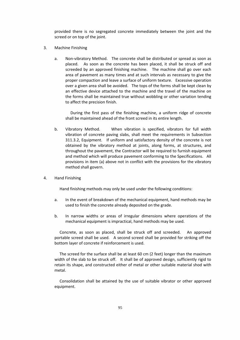
provided there is no segregated concrete immediately between the joint and the screed or on top of the joint.
3. Machine Finishing
a. Non-vibratory Method. The concrete shall be distributed or spread as soon as placed. As soon as the concrete has been placed, it shall be struck off and screeded by an approved finishing machine. The machine shall go over each area of pavement as many times and at such intervals as necessary to give the proper compaction and leave a surface of uniform texture. Excessive operation over a given area shall be avoided. The tops of the forms shall be kept clean by an effective device attached to the machine and the travel of the machine on the forms shall be maintained true without wobbling or other variation tending to affect the precision finish.
During the first pass of the finishing machine, a uniform ridge of concrete shall be maintained ahead of the front screed in its entire length.
b. Vibratory Method. When vibration is specified, vibrators for full width
vibration of concrete paving slabs, shall meet the requirements in Subsection 311.3.2, Equipment. If uniform and satisfactory density of the concrete is not obtained by the vibratory method at joints, along forms, at structures, and throughout the pavement, the Contractor will be required to furnish equipment and method which will produce pavement conforming to the Specifications. All provisions in item (a) above not in conflict with the provisions for the vibratory method shall govern.
4. Hand Finishing
Hand finishing methods may only be used under the following conditions:
a. In the event of breakdown of the mechanical equipment, hand methods may be used to finish the concrete already deposited on the grade.
b. In narrow widths or areas of irregular dimensions where operations of the
mechanical equipment is impractical, hand methods may be used.
Concrete, as soon as placed, shall be struck off and screeded. An approved portable screed shall be used. A second screed shall be provided for striking off the bottom layer of concrete if reinforcement is used. The screed for the surface shall be at least 60 cm (2 feet) longer than the maximum width of the slab to be struck off. It shall be of approved design, sufficiently rigid to retain its shape, and constructed either of metal or other suitable material shod with metal. Consolidation shall be attained by the use of suitable vibrator or other approved equipment.

96
In operation, the screed shall be moved forward on the forms with a combined longitudinal and transverse shearing motion, moving always in the direction in which the work is progressing and so manipulated that neither end is raised from the side forms during the striking off process. If necessary, this shall be repeated until the surface is of uniform texture, true to grade and cross-section, and free from porous areas.
5. Floating
After the concrete has been struck off and consolidated, it shall be further smoothed, trued, and consolidated by means of a longitudinal float, either by hand or mechanical method.
a. Hand Method. The hand-operated longitudinal float shall be not less than 365
cm (12 feet) in length and 15 cm (6 inches) in width, properly stiffened to prevent flexibility and warping. The longitudinal float, operated from foot bridges resting on the side forms and spanning but not touching the concrete, shall be worked with a sawing motion while held in a floating position parallel to the road center line, and moving gradually from one side of the pavement to the other. Movement ahead along the center line of the pavement shall be in successive advances of not more than one-half the length of the float. Any excess water or soupy material shall be wasted over the side forms on each pass.
b. Mechanical Method. The mechanical longitudinal float shall be of a design
approved by the Engineer, and shall be in good working condition. The tracks from which the float operates shall be accurately adjusted to the required crown. The float shall be accurately adjusted and coordinated with the adjustment of the transverse finishing machine so that a small amount of mortar is carried ahead of the float at all times. The forward screed shall be adjusted so that the float will lap the distance specified by the Engineer on each transverse trip. The float shall pass over each areas of pavement at least two times, but excessive operation over a given area will not be permitted. Any excess water or soupy material shall be wasted over the side forms on each pass.
c. Alternative Mechanical Method. As an alternative, the Contractor may use a
machine composed of a cutting and smoothing float or floats suspended from and guided by a rigid frame. The frame shall be carried by four or more visible wheels riding on, and constantly in contact with the side forms. If necessary, following one of the preceding method of floating, long handled floats having blades not less than 150 cm (5 feet) in length and 15 cm (6 inches) in width may be used to smooth and fill in open-textured areas in the pavement. Long-handled floats shall not be used to float the entire surface of the pavement in lieu of, or supplementing, one of the preceding methods of floating. When strike off and consolidation are done by the hand method and the crown of the pavement will not permit the use of the longitudinal float, the surface shall be floated transversely by means of the long-handled float. Care shall be taken not to work the crown out of the pavement during the operation. After floating, any excess water and laitance shall be removed from the surface of the

97
pavement by a 3-m straight-edge or more in length. Successive drags shall be lapped one-half the length of the blade.
6. Straight-edge Testing and Surface Correction
After the floating has been completed and the excess water removed, but while the concrete is still plastic, the surface of the concrete shall be tested for trueness with a 300 cm long straight-edge. For this purpose, the Contractor shall furnish and use an accurate 300-cm straight-edge swung from handles 100 cm (3 feet) longer than one-half the width of the slab. The straight-edge shall be held in contact with the surface in successive positions parallel to the road center line and the whole area gone over from one side of the slab to the other as necessary. Advances along the road shall be in successive stages of not more than one-half the length of the straight-edge. Any depressions found shall be immediately filled with freshly mixed concrete, struck off, consolidated and refinished. High areas shall be cut down and refinished. Special attention shall be given to assure that the surface across joints meets the requirements for smoothness. Straight-edge testing and surface corrections shall continue until the entire surface is found to be free from observable departures from the straight-edge and the slab conforms to the required grade and cross-section.
7. Final Finish
If the surface texture is broom finished, it shall applied when the water sheen has practically disappeared. The broom shall be drawn from the center to the edge of the pavement with adjacent strokes slightly overlapping. The brooming operation should be so executed that the corrugations produced in the surface shall be uniform in appearance and not more than 1.5 mm in depth. Brooming shall be completed before the concrete is in such condition that the surface will be unduly roughened by the operation. The surface thus finished shall be free from rough and porous areas, irregularities, and depressions resulting from improper handling of the broom. Brooms shall be of the quality size and construction and be operated so as to produce a surface finish meeting the approval of the Engineer. Subject to satisfactory results being obtained and approval of the Engineer, the Contractor will be permitted to substitute mechanical brooming in lieu of the manual brooming herein described. If the surface texture is belt finished, when straight-edging is complete and water sheen has practically disappeared and just before the concrete becomes non-plastic, the surface shall be belted with 2-ply canvass belt not less than 20 cm wide and at least 100 cm longer than the pavement width. Hand belts shall have suitable handles to permit controlled, uniform manipulation. The belt shall be operated with short strokes transverse to the center line and with a rapid advances parallel to the center line. If the surface texture is drag finished, a drag shall be used which consists of a seamless strip of damp burlap or cotton fabric, which shall produce a uniform of gritty texture after dragging it longitudinally along the full width of pavement. For pavement 5 m or more in width, the drag shall be mounted on a bridge which travels on the forms. The dimensions of the drag shall be such that a strip of burlap or fabric at least 100 cm wide is in contact with the full width of pavement surface while the drag is used. The drag shall consist of not less than 2 layers of burlap with the bottom layer

98
approximately 15 cm wider than the layer. The drag shall be maintained in such condition that the resultant surface is of uniform appearance and reasonably free from grooves over 1.5 mm in depth. Drag shall be maintained clean and free from encrusted mortar. Drags that cannot be cleaned shall be discarded and new drags be substituted. Regardless of the method used for final finish, the hardened surface of pavement shall have a coefficient of friction of 0.25 or more. Completed pavement that is found to have a coefficient of friction less than 0.25 shall be grounded or scored by the Contractor at his expense to provide the required coefficient of friction.
8. Edging at Forms and Joints
After the final finish, but before the concrete has taken its initial set, the edges of the pavement along each side of each slab, and on each side of transverse expansion joints, formed joints, transverse construction joints, and emergency construction joints, shall be worked with an approved tool and rounded to the radius required by the Plans. A well – defined and continuous radius shall be produced and a smooth, dense mortar finish obtained. The surface of the slab shall not be unduly disturbed by tilting the tool during the use. At all joints, any tool marks appearing on the slab adjacent to the joints shall be eliminated by brooming the surface. In doing this, the rounding of the corner of the slab shall not be disturbed. All concrete on top of the joint filler shall be completely removed. All joints shall be tested with a straight-edge before the concrete has set and correction made if one edge of the joint is higher than the other.
311.3.14 Surface Test
As soon as the concrete has hardened sufficiently, the pavement surface shall be tested with a 3-m straight-edge or other specified device. Areas showing high spots of more than 3 mm but not exceeding 12 mm in 3 m shall be marked and immediately ground down with an approved grinding tool to an elevation where the area or spot will not show surface deviations in excess of 3 mm when tested with 3 m straight-edge. Where the departure from correct cross-section exceeds 12 mm, the pavement shall be removed and replaced by and at the expense of the Contractor. Any area or section so removed shall be not less than 1.5 m in length and not less than the full width of the lane involved. When it is necessary to remove and replace a section of pavement, any remaining portion of the slab adjacent to the joints that is less than 1.5 m in length, shall also be removed and replaced.
311.3.15 Curing
Immediately after the finishing operations have been completed and the concrete has sufficiently set, the entire surface of the newly placed concrete shall be cured in accordance with either one of the methods described herein. Failure to provide sufficient cover material of whatever kind the Contractor may elect to use, or the lack of water to adequately take care of

99
both curing and other requirements, shall be a cause for immediate suspension of concreting operations. The concrete shall not be left exposed for more than ½ hour between stages of curing or during the curing period. In all congested places, concrete works should be designed so that the designed strength is attained.
1. Cotton of Burlap Mats
The surface of the pavement shall be entirely covered with mats. The mats used shall be of such length (or width) that as laid they will extend at least twice the thickness of the pavement beyond the edges of the slab. The mat shall be placed so that the entire surface and the edges of the slab are completely covered. Prior to being placed, the mats shall be saturated thoroughly with water. The mat shall be so placed and weighted down so as to cause them to remain in intimate contact with the covered surface. The mat shall be maintained fully wetted and in position for 72 hours after the concrete has been placed unless otherwise specified.
2. Waterproof Paper
The top surface and sides of the pavement shall be entirely covered with waterproof paper, the units shall be lapped at least 45 cm. The paper shall be so placed and weighted down so as to cause it to remain in intimate contact with the surface covered. The paper shall have such dimension but each unit as laid will extend beyond the edges of the slab at least twice the thickness of the pavement, or at pavement width and 60 cm strips of paper for the edges. If laid longitudinally, paper not manufactured in sizes which will provide this width shall be securely sewed or cemented together, the joints being securely sealed in such a manner that they do not open up or separate during the curing period. Unless otherwise specified, the covering shall be maintained in place for 72 hours after the concrete has been placed. The surface of the pavement shall be thoroughly wetted prior to the placing of the paper.
3. Straw Curing
When this type of curing is used, the pavement shall be cured initially with burlap or cotton mats, until after final set of the concrete or, in any case, for 12 hours after placing the concrete. As soon as the mats are removed, the surface and sides of the pavement shall be thoroughly wetted and covered with at least 20 cm of straw or hay, thickness of which is to be measured after wetting. If the straw or hay covering becomes displaced during the curing period, it shall be replaced to the original depth and saturated. It shall be kept thoroughly saturated with water for 72 hours and thoroughly wetted down during the morning of the fourth day, and the cover shall remain in place until the concrete has attained the required strength.
4. Impervious Membrane Method
The entire surface of the pavement shall be sprayed uniformly with white pigmented curing compound immediately after the finishing of the surface and before the set of the concrete has taken place, or if the pavement is cured initially with jute

100
or cotton mats, it may be applied upon removal of the mass. The curing compound shall not be applied during rain. Curing compound shall be applied under pressure at the rate 4 L to not more than 14 m2 by mechanical sprayers. The spraying equipment shall be equipped with a wind guard. At the time of use, the compound shall be in a thoroughly mixed condition with the pigment uniformly dispersed throughout the vehicle. During application, the compound shall be stirred continuously by effective mechanical means. Hand spraying of odd widths or shapes and concrete surface exposed by the removal of forms will be permitted. Curing compound shall not be applied to the inside faces of joints to be sealed, but approved means shall be used to insure proper curing at least 72 hours and to prevent the intrusion of foreign material into the joint before sealing has been completed. The curing compound shall be of such character that the film will harden within 30 minutes after application. Should the film be damaged from any cause within the 72 hour curing period, the damaged portions shall be repaired immediately with additional compound.
5. White Polyethylene Sheet
The top surface and sides of the pavement shall be entirely covered with polyethylene sheeting. The units used shall be lapped at least 45 cm. The sheeting shall be so placed and weighted down so as to cause it to remain intimate contact with the surface covered. The sheeting as prepared for use shall have such dimension that each unit as laid will extend beyond the edges of the slab at least twice the thickness of the pavement. Unless otherwise specified, the covering shall be maintained in place for 72 hours after the concrete has been placed.
311.3.16 Removal of Forms
After forms for concrete shall remain in place undisturbed for not less than twenty four (24) hours after concrete pouring. In the removal of forms, crowbars should be used in pulling out nails and pins. Care should be taken so as not to break the edges of the pavement. In case portions of the concrete are spalled, they shall be immediately repaired with fresh mortar mixed in the proportion of one part of Portland Cement and two parts fine aggregates. Major honeycomb areas will be considered as defective work and shall be removed and replaced at the expense of the Contractor. Any area or section so removed shall not be less than the distance between weakened plane joint nor less than the full width of the lane involved.
311.3.17 Sealing Joints
Joints shall be sealed with asphalt sealant soon after completion of the curing period and before the pavement is opened to traffic, including the Contractor’s equipment. Just prior to sealing, each joint shall be thoroughly cleaned of all foreign materials including membrane curing compound and the joint faces shall be clean and surface dry when the seal is applied. The sealing material shall be applied to each joint opening to conform to the details shown on the Plans or as directed by the Engineer. Material for seal applied hot shall be stirred during heating so that localized overheating does not occur. The pouring shall be done in such a manner that the material will not be spilled on the exposed surfaces of the concrete. The use of sand or similar material as a cover for the seal will not be permitted.

101
Preformed elastomeric gaskets for sealing joints shall be of the cross-sectional dimensions shown on the Plans. Seals shall be installed by suitable tools, without elongation and secured in placed with an approved lubricant adhesive which shall cover both sides of the concrete joints. The seals shall be installed in a compressive condition and shall at time of placement be below the level of the pavement surface by approximately 6 mm. The seals shall be in one piece for the full width of each transverse joint.
311.3.18 Protection of Pavement
The Contractor shall protect the pavement and its appurtenances against both public traffic and traffic caused by his own employees and agents. This shall include watchmen to direct traffic and the erection of and maintenance of warning signs, lights, pavement bridges or cross-overs, etc. The Plans or Special Provisions will indicate the location and type of device or facility required to protect the work and provide adequately for traffic. All boreholes after thickness and/or strength determinations of newly constructed asphalt and concrete pavements shall be immediately filled/restored with the prescribed concrete/asphalt mix after completion of the drilling works. Any damage to the pavement, occurring prior to final acceptance, shall be repaired or the pavement be replaced.
311.3.19 Concrete Pavement – Slip Form Method
If the Contract calls for the construction of pavement without the use of fixed forms, the following provisions shall apply:
1. Grade
After the grade or base has been placed and compacted to the required density, the areas which will support the paving machine shall be cut to the proper elevation by means of a properly designed machine. The grade on which the pavement is to be constructed shall then be brought to the proper profile by means of properly designed machine. If the density of the base is disturbed by the grading operation, it shall be corrected by additional compaction before concrete is placed. The grade should be constructed sufficiently in advance of the placing of the concrete. If any traffic is allowed to use the prepared grade, the grade shall be checked and corrected immediately before the placing of concrete.
2. Placing Concrete
The concrete shall be placed with an approved slip-form paver designed to spread, consolidate, screed and float-finish the freshly placed concrete in one complete pass of the machine in such a manner that a minimum of hand finish will be necessary to provide a dense and homogenous pavement in conformance with the Plans and Specifications. The machine shall vibrate the concrete for the full width and depth of the strip of pavement being placed. Such vibration shall be accompanied with vibrating tubes or arms working in the concrete or with a vibrating screed or pan

102
operating on the surface of the concrete. The sliding forms shall be rigidly held together laterally to prevent spreading of the forms. The forms shall trail behind the paver for such a distance that no appreciable slumping of the concrete will occur, and that necessary final finishing can be accomplished while the concrete is still within the forms. Any edge slump of the pavement, exclusive of edge rounding, in excess of 6 mm shall be corrected before the concrete has hardened. The concrete shall be held at a uniform consistency, having a slump of not more than 40 mm (1-12/ inches). The slip form paver shall be operated with as nearly as possible a continuous forward movement and that all operations of mixing, delivering and spreading concrete shall be coordinated so as to provide uniform progress with stopping and starting of the paver held to a minimum. If, for any reason, it is necessary to stop the forward movement of the paver the vibratory and tamping elements shall also be stopped immediately. No tractive force shall be applied to the machine, except that which is controlled from the machine.
3. Finishing
The surface smoothness and texture shall meet the requirements of Subsections 311.3.13 and 311.3.14.
4. Curing
Unless otherwise specified, curing shall be done in accordance with one of the methods included in Subsection 311.3.15. The curing media shall be applied at the appropriate time and shall be applied uniformly and completely to all surfaces and edges of the pavement.
5. Joints
All joints shall be constructed in accordance with Subsection 311.3.12.
6. Protection Against Rain
In order that the concrete may be properly protected against rain before the concrete is sufficiently hardened, the Contractor will be required to have available at all times, materials for the protection of the edges and surface of the unhardened concrete. Such protective materials shall consist of standard metal forms or wood planks having a nominal thickness of not less than 50 mm (2 inches) and a nominal width of not less than the thickness of the pavement at its edge for the protection of the pavement edges, and covering material such as burlap or cotton mats, curing paper or plastic sheeting materials for the protection of the surface of the pavement. When rain appears imminent, all paving operations shall stop and all available personnel shall begin placing forms against the sides of the pavement and covering the surface of the unhardened concrete with the protective covering.
311.3.22 Acceptance of Concrete
The strength level of the concrete will be considered satisfactory if the averages of all sets of three (3) consecutive strength test results equal or exceed the specified strength, fc’ and no individual strength test result is deficient by more than 15% of the specified strength, fc’.

103
Concrete deemed to be not acceptable using the above criteria may be rejected unless the Contractor can provide evidence, by means of core tests, that the quality of concrete represented by failed test results is acceptable in place. At least three (3) representative cores shall be taken from each member or area of concrete in place that is considered deficient. The location of cores shall be determined by the Engineer so that there will be at least impairment of strength of the structure. The obtaining and testing of drilled cores shall be in accordance with AASHTO T 24. Concrete in the area represented by the cores will be considered adequate if the average strength of the cores is equal to at least 85% of, and if no single core is less than 75% of, the specified strength, fc’. If the strength of control specimens does not meet the requirements of this Subsection, and it is not feasible or not advisable to obtain cores from the structure due to structural considerations, payment of the concrete will be made at an adjusted price due to strength deficiency of concrete specimens as specified hereunder:
Deficiency in Strength of Concrete Specimens,
Percent (%)
Percent (%) of Contract
Price Allowed
Less than 5 100
5 to less than 10 80
10 to less than 15 70
15 to less than 20 60
20 to less than 25 50
25 or more 0
311.3.23 Opening to Traffic
The Engineer will decide when the pavement may be opened to traffic. The road will not be opened to traffic until test specimens molded and cured in accordance with AASHTO T 23 have attained the minimum strength requirements in Subsection 311.2.11. If such tests are not conducted prior to the specified age the pavement shall not be operated to traffic until 14 days after the concrete was placed. Before opening to traffic, the pavement shall be cleaned and joint sealing completed.
311.3.24 Tolerance and Pavement thickness 1. General
The thickness of the pavement will be determined by measurement of cores from the completed pavement in accordance with AASHTO T 148. The completed pavement shall be accepted on a lot basis. A lot shall be considered as 1000 linear meters of pavement when a single traffic lane is poured or 500 linear meters when two lanes are poured concurrently. The last unit in each slab constitutes

104
a lot in itself when its length is at least ½ of the normal lot length. If the length of the last unit is shorter than ½ of the normal lot length, it shall be included in the previous lot. Other areas such as intersections, entrances, crossovers, ramp, etc., will be grouped together to form a lot. Small irregular areas may be included with other unit areas to form a lot.
Each lot will be divided into five (5) equal segments and one core will be obtained from each segment in accordance with AASHTO T 24.
2. Pavement Thickness
It is the intent of this Specification that the pavement has a uniform thickness as called for on the Plans for the average of each lot as defined. After the pavement has met all surface smoothness requirements, cores for thickness measurements will be taken. In calculating the average thickness of the pavement, individual measurements which are in excess of the specified thickness by more than 5 mm will be considered as the specified thickness plus 5 mm and measurement which are less than the specified thickness by more than 25 mm shall not be included in the average. When the average thickness for the lot is deficient, the contract unit price will be adjusted for thickness in accordance with paragraph (3 below). Individual areas within a segment found deficient in thickness by more than 25 mm shall be evaluated by the Engineer, and if in his judgment, the deficient areas warrant removal, they shall be removed and replaced by the Contractor with pavement of the specified thickness at his entire expense. However, if the evaluation of the Engineer is that the deficient area should not be removed and replaced; such area will not be paid. When the measurement of any core is less than the specified thickness by more than 25 mm, the actual thickness of the pavement in this area will be determined by taking additional cores at no less than 5 m intervals parallel to the center line in each direction from the affected location until a core is found in each direction, which is not deficient in thickness by more than 25 mm. The area of slab for which no payment will be made shall be the product of the paving width multiplied by the distance along the center line of the road between transverse sections found not deficient in thickness by more than 25 mm. The thickness of the remainder of the segment to be used to get the average thickness of each lot shall be determined by taking the average thickness of additional cores which are not deficient by more than 25 mm.
3. Adjustment for Thickness
When the average thickness of the pavement per lot is deficient, payment for the lot shall be adjusted as follows:

105
Deficiency in the Average
Thickness per lot (mm)
Percent (%) of Contract Price Per Lot
0 – 5 100% payment
6 – 10 95% payment
11 – 15 85% payment
16 – 20 70% payment
21 – 25 50% payment
More than 25
Remove and replace/ No payment
No acceptance and final payment shall be made on completed pavement unless core test for thickness determination is conducted, except for Barangay Roads where the implementing office is allowed to waive such test.
311.4 Method of Measurement
The area to be paid for under this Item shall be the number of square meters (m2) of concrete pavement placed and accepted in the completed pavement. The width for measurements will be the width from outside edge to outside edge of completed pavement as placed in accordance with the Plans or as otherwise required by the Engineer in writing. The length will be measured horizontally along the center line of each roadway or ramp. Any curb and gutter placed shall not be included in the area of concrete pavement measured.
311.5 Basis of Payment The accepted quantity, measured as prescribed in Section 311.4, shall be paid for at the contract unit price for Portland Cement Concrete Pavement, which price and payment shall be full compensation for preparation of roadbed and finishing of shoulders, unless otherwise provided by the Special Provisions, furnishing all materials, for mixing, placing, finishing and curing all concrete, for furnishing and placing all joint materials, for sawing weakened plane joints, for fitting the prefabricated center metal joint, for facilitating and controlling traffic, and for furnishing all labor, equipment, tools and incidentals necessary to complete the Item.
Payment will be made under:
Pay Item Number
Description Unit of Measurement
311 (1) PCC Pavement (Plain)
Square meter
311 (2) PCC Pavement (Reinforced)
Square meter

106
ITEM 405 – STRUCTURAL CONCRETE
405.1 Description 405.1.1 Scope
This Item shall consist of furnishing, bending, placing and finishing concrete in all structures except pavements in accordance with this Specification and conforming to the lines, grades, and dimensions shown on the Plans. Concrete shall consist of a mixture of Portland Cement, fine aggregate, coarse aggregate, admixture when specified, and water mixed in the proportions specified or approved by the Engineer.
405.1.2 Classes and Uses of Concrete
Five classes of concrete are provided for in this Item, namely: A, B, C, P and Seal. Each class shall be used in that part of the structure as called for on the Plans. The classes of concrete will generally be used as follows: Class A – All superstructures and heavily reinforced substructures. The important parts of the structure included are slabs, beams, girders, columns, arch ribs, box culverts, reinforced abutments, retaining walls, and reinforced footings. Class B – Footings, pedestals, massive pier shafts, pipe bedding, and gravity walls, unreinforced or with only a small amount of reinforcement. Class C – Thin reinforced sections, railings, precast R.C. piles and cribbing and for filler in steel grid floors. Class P – Prestressed concrete structures and members. Seal – Concrete deposited in water.
405.2 Material Requirements 405.2.1 Portland Cement
It shall conform to all the requirements of Subsection 311.2.1.
405.2.2 Fine Aggregate
It shall conform to all the requirements of Subsection 311.2.2.

107
405.2.3 Coarse Aggregate
It shall conform all the requirements of Subsection 311.2.3 except that gradation shall conform to Table 405.1.
Table 405.1 – Grading Requirements for Coarse Aggregate
Sieve Designation Mass Percent Passing
Standard Mm
Alternate US Standard
Class A
Class B
Class C
Class P
Class Seal
63 50 37.5 25 19.0 12.5 9.5 4.75
2-1/2” 2” 1-1/2” 1” ¾” ½” 3/8” No.4
100 95 – 100 - 35 – 70 - 10 – 30
0 - 5
100 95 – 100 - 35 – 70 - 10 – 30 - 0 - 5
100 90 – 100 40 – 70
0 – 15*
100 95 – 100 - 20 – 55 0 – 10*
100 95 – 100 - 25 – 60 - 0 – 10*
* The measured cement content shall be within plus (+) or minus (-) 2 mass percent of the
design cement content. 405.2.4 Water
It shall conform to the requirements of Subsection 311.2.4 405.2.5 Reinforcing Steel
It shall conform to the requirements of Item 710, Reinforcing Steel and Wire Rope.
405.2.6 Admixtures
Admixtures shall conform to the requirements of Subsection 311.2.7
405.2.7 Curing Materials
Curing materials shall conform to the requirements of Subsection 311.2.8.
405.2.8 Expansion Joint Materials
Expansion joint materials shall be: 1. Preformed Sponge Rubber and Cork, conforming to AASHTO M 153. 2. Hot-Poured Elastic Type, conforming to AASHTO M 173.
3. Preformed Fillers, conforming to AASHTO M 213.

108
405.2.9 Elastomeric Compression Joint Seals
These shall conform to AASHTO M 220.
405.2.10 Elastomeric Bearing Pads
These shall conform to AASHTO M 251 or Item 412 – Elastomeric Bearing Pads.
405.2.11 Storage of Cement and Aggregates
Storage of cement and aggregates shall conform to all the requirements of Subsection 311.2.10. 405.3 Sampling and Testing of Structural Concrete
As work progresses, at least one (1) sample consisting of three (3) concrete cylinder test specimens, 150 x 300mm (6 x 12 inches), shall be taken from each seventy five (75) cubic meters of each class of concrete or fraction thereof placed each day.
Compliance with the requirements of this Section shall be determined in accordance with
the following standard methods of AASHTO:
Sampling of fresh concrete Weight per cubic metre and air content (gravi- Metric) of concrete Sieve analysis of fine and coarse aggregates Slump of Portland Cement Concrete Specific gravity and absorption of fine aggregate
T 141 T 121 T 27 T 119 T 84
Tests for strength shall be made in accordance with the following:
Making and curing concrete compressive and flexural tests specimens in the field Compressive strength of molded concrete Cylinders
T 23 T 22
405.4 Production Requirements 405.4.1 Proportioning and Strength of Structural Concrete
The concrete materials shall be proportioned in accordance with the requirements for each class of concrete as specified in Table 405.2, using the absolute volume method as outlined in the American Concrete Institute (ACI) Standard 211.1. “Recommended Practice for Selecting Proportions for Normal and Heavyweight Concrete”. Other methods of proportioning may be employed in the mix design with prior approval of the Engineer. The mix shall either be designed or approved by the Engineer. A change in the source of materials during the progress of work may necessitate a new mix design.
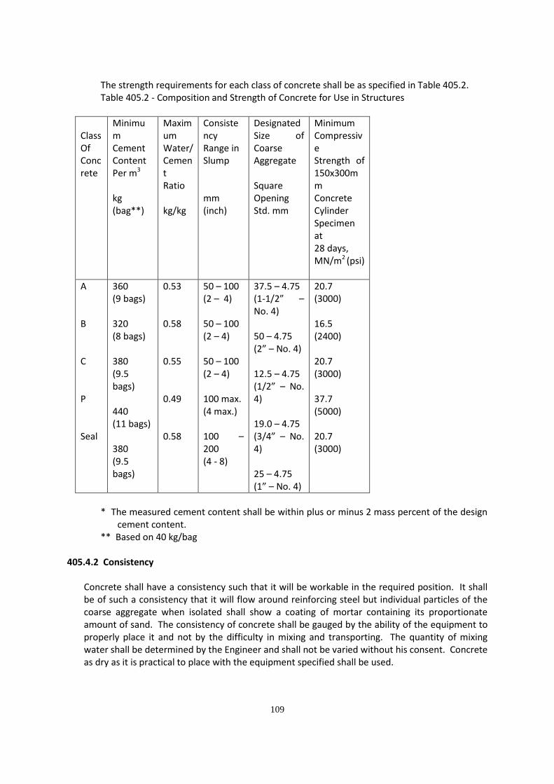
109
The strength requirements for each class of concrete shall be as specified in Table 405.2. Table 405.2 - Composition and Strength of Concrete for Use in Structures
Class Of Concrete
Minimum Cement Content Per m3 kg (bag**)
Maximum Water/ Cement Ratio kg/kg
Consistency Range in Slump mm (inch)
Designated Size of Coarse Aggregate Square Opening Std. mm
Minimum Compressive Strength of 150x300mm Concrete Cylinder Specimen at 28 days, MN/m2 (psi)
A B C P Seal
360 (9 bags) 320 (8 bags) 380 (9.5 bags) 440 (11 bags) 380 (9.5 bags)
0.53 0.58 0.55 0.49 0.58
50 – 100 (2 – 4) 50 – 100 (2 – 4) 50 – 100 (2 – 4) 100 max. (4 max.) 100 – 200 (4 - 8)
37.5 – 4.75 (1-1/2” – No. 4) 50 – 4.75 (2” – No. 4) 12.5 – 4.75 (1/2” – No. 4) 19.0 – 4.75 (3/4” – No. 4) 25 – 4.75 (1” – No. 4)
20.7 (3000) 16.5 (2400) 20.7 (3000) 37.7 (5000) 20.7 (3000)
* The measured cement content shall be within plus or minus 2 mass percent of the design
cement content. ** Based on 40 kg/bag
405.4.2 Consistency
Concrete shall have a consistency such that it will be workable in the required position. It shall be of such a consistency that it will flow around reinforcing steel but individual particles of the coarse aggregate when isolated shall show a coating of mortar containing its proportionate amount of sand. The consistency of concrete shall be gauged by the ability of the equipment to properly place it and not by the difficulty in mixing and transporting. The quantity of mixing water shall be determined by the Engineer and shall not be varied without his consent. Concrete as dry as it is practical to place with the equipment specified shall be used.

110
405.4.3 Batching
Measuring and batching of materials shall be done at a batching plant. 1. Portland Cement
Either sacked or bulk cement may be used. No fraction of a sack of cement shall be used in a batch of concrete unless the cement is weighed. All bulk cement shall be weighed on an approved weighing device. The bulk cement weighing hopper shall be properly sealed and vented to preclude dusting operation. The discharge chute shall not be suspended from the weighing hopper and shall be so arranged that cement will neither be lodged in it nor leak from it.
Accuracy of batching shall be within plus (+) or minus (-) 1 mass percent.
2. Water
Water may be measured either by volume or by weight. The accuracy of measuring the water shall be within a range of error of not more than 1 percent.
3. Aggregates
Stockpiling of aggregates shall be in accordance with Subsection 311.2.10. All aggregates whether produced or handled by hydraulic methods or washed, shall be stockpiled or binned for draining for at least 12 hours prior to batching. Rail shipment requiring more than12 hours will be accepted as adequate binning only if the car bodies permit free drainage. If the aggregates contain high or non-uniform moisture content, storage or stockpile period in excess of 12 hours may be required by the Engineer.
Batching shall be conducted as to result in a 2 mass percent maximum tolerance for
the required materials.
4. Bins and Scales
The batching plant shall include separate bins for bulk cement, fine aggregate and for each size of coarse aggregate, a weighing hopper, and scales capable of determining accurately the mass of each component of the batch.
Scales shall be accurate to one-half (0.5) percent throughout the range used.
5. Batching When batches are hauled to the mixer, bulk cement shall be transported either in
waterproof compartments or between the fine and coarse aggregate. When cement is placed in contact with moist aggregates, batches will be rejected unless mixed within 1-1/2 hours of such contact. Sacked cement may be transported on top of the aggregates.
Batches shall be delivered to the mixer separate and intact. Each batch shall be
dumped cleanly into the mixer without loss, and, when more than one batch is carried on the truck, without spilling of material from one batch compartment into another.

111
6. Admixtures
The Contractor shall follow an approved procedure for adding the specified amount of admixture to each batch and will be responsible for its uniform operation during the progress of the work. He shall provide separate scales for the admixtures which are to be proportioned by weight, and accurate measures for those to be proportioned by volume. Admixtures shall be measured into the mixer with an accuracy of plus or minus three (3) percent.
The use of Calcium Chloride as an admixture will not be permitted.
405.4.4 Mixing and Delivery Concrete may be mixed at the site of construction, at a central point or by a combination of central point and truck mixing or by a combination of central point mixing and truck agitating. Mixing and delivery of concrete shall be in accordance with the appropriate requirements of AASHTO M 157 except as modified in the following paragraphs of this section, for truck mixing or a combination of central point and truck mixing or truck agitating. Delivery of concrete shall be regulated so that placing is at a continuous rate unless delayed by the placing operations. The intervals between delivery of batches shall not be so great as to allow the concrete inplace to harden partially, and in no case shall such an interval exceed 30 minutes. In exceptional cases and when volumetric measurements are authorized, for small project requiring less than 75 cu.m. per day of pouring, the weight proportions shall be converted to equivalent volumetric proportions. In such cases, suitable allowance shall be made for variations in the moisture condition of the aggregates, including the bulking effect in the fine aggregate. Batching and mixing shall be in accordance with ASTM C 685, Section 6 through 9. Concrete mixing, by chute is allowed provided that a weighing scales for determining the batch weight will be used. For batch mixing at the site of construction or at a central point, a batch mixer of an approved type shall be used. Mixer having a rated capacity of less than a one-bag batch shall not be used. The volume of concrete mixed per batch shall not exceed the mixer’s nominal capacity as shown on the manufacturer’s standard rating plate on the mixer except that an overload up to 10 percent above the mixer’s nominal capacity may be permitted, provided concrete test data for strength, segregation, and uniform consistency are satisfactory and provided no spillage of concrete takes place. The batch shall be so charge into the drum that a portion of the water shall enter in advance of the cement and aggregates. The flow of water shall be uniform and all water shall be in the drum by the end of the first 15 seconds of the mixing period. Mixing time shall be measured from the time all materials, except water, are in the drum. Mixing time shall not be less than 60 seconds for mixers having a capacity of 1.5m3 or less. For mixers having a capacity greater than 1.5m3, the mixing time shall not be less than 90 seconds. If timing starts, the instant the skip reaches its maximum raised position, 4 seconds shall be added to the specified mixing time. Mixing time ends when the discharge chute opens. The mixer shall be operated at the drum speed as shown on the manufacturer’s name plate on the mixer. Any concrete mixed less than the specified time shall be discarded and disposed off by the Contractor at his own expenses.

112
The timing device on stationary mixers shall be equipped with a bell or other suitable warning device adjusted to give a clearly audible signal each time the lock is released. In case of failure of the timing device, the Contractor will be permitted to continue operations while it is being repaired, provided he furnishes an approved timepiece equipped with minute and second hands. If the timing device is not placed in good working order within 24 hours, further use of the mixer will be prohibited until repairs are made. Retempering concrete will not be permitted. Admixtures for increasing the workability, for retarding the set, or for accelerating the set or improving the pumping characteristics of the concrete will be permitted only when specifically provided for in the Contract, or authorized in writing by the Engineer.
1. Mixing Concrete: General
Concrete shall be thoroughly mixed in a mixer of an approved size and type that will insure a uniform distribution of the materials throughout the mass.
All concrete shall be mixed in mechanically operated mixers. Mixing plant and
equipment for transporting and placing concrete shall be arranged with an ample auxiliary installation to provide a minimum supply of concrete in case of breakdown of machinery or in case the normal supply of concrete is disrupted. The auxiliary supply of concrete shall be sufficient to complete the casting of a section up to a construction joint that will meet the approval of the Engineer.
Equipment having components made of aluminum or magnesium alloys, which
would have contact with plastic concrete during mixing, transporting or pumping of Portland Cement concrete, shall not be used.
Concrete mixers shall be equipped with adequate water storage and a device of
accurately measuring and automatically controlling the amount of water used. Materials shall be measured by weighing. The apparatus provided for weighing the
aggregates and cement shall be suitably designed and constructed for this purpose. The accuracy of all weighing devices except that for water shall be such that successive quantities can be measured to within one percent of the desired amounts. The water measuring device shall be accurate to plus or minus 0.5 mass percent. All measuring devices shall be subject to the approval of the Engineer. Scales and measuring devices shall be tested at the expense of the Contractor as frequently as the Engineer may deem necessary to insure their accuracy.
Weighing equipment shall be insulated against vibration or movement of other
operating equipment in the plant. When the entire plant is running, the scale reading at cut-off shall not vary from the weight designated by the Engineer more than one mass percent for cement, 1-1/2 mass percent for any size of aggregate, or one (1) mass percent for the total aggregate in any batch.

113
2. Mixing Concrete at Site Concrete mixers may be of the revolving drum or the revolving blade type and the
mixing drum or blades shall be operated uniformly at the mixing speed recommended by the manufacturer. The pick-up and throw-over blades of mixers shall be restored or replaced when any part or section is worn 20mm or more below the original height of the manufacturer’s design. Mixers and agitators which have an accumulation of hard concrete or mortar shall not be used.
When bulk cement is used and volume of the batch is 0.5m3 or more, the scale and
weigh hopper for Portland Cement shall be separate and distinct from the aggregate hopper or hoppers. The discharge mechanism of the bulk cement weigh hopper shall be interlocked against opening before the full amount of cement is in the hopper. The discharging mechanism shall also be interlocked against opening when the amount of cement in the hopper is underweight by more than one (1) mass percent or overweight by more than 3 mass percent of the amount specified.
When the aggregate contains more water than the quantity necessary to produce a
saturated surface dry condition, representative samples shall be taken and the moisture content determined for each kind of aggregate.
The batch shall be so charged into the mixer that some water will enter in advance
of cement and aggregate. All water shall be in the drum by the end of the first quarter of the specified mixing time.
Cement shall be batched and charged into the mixer so that it will not result in loss
of cement due to the effect of wind, or in accumulation of cement on surface of conveyors or hoppers, or in other conditions which reduce or vary the required quantity of cement in the concrete mixture.
The entire content of a batch mixer shall be removed from the drum before
materials for a succeeding batch are placed therein. The materials composing a batch except water shall be deposited simultaneously into the mixer.
All concrete shall be mixed for a period of not less than 1-1/2 minutes after all
materials, including water, are in the mixer. During the period of mixing, the mixer shall operate at the speed for which it has been designed.
Mixers shall be operated with an automatic timing device that can be locked by the
Engineer. The time device and discharge mechanics shall be so interlocked that during normal operation no part of the batch will be charged until the specified mixing time has elapsed.
The first batch of concrete materials placed in the mixer shall contain a sufficient
excess of cement, sand, and water to coat inside of the drum without reducing the required mortar content of the mix. When mixing is to cease for a period of one hour or more, the mixer shall be thoroughly cleaned.

114
3. Mixing Concrete at Central Plant
Mixing at central plant shall conform to the requirements for mixing at the site. 4. Mixing Concrete in Truck
Truck mixers, unless otherwise authorized by the Engineer, shall be of the revolving drum type, water-tight, and so constructed that the concrete can be mixed to insure a uniform distribution of materials throughout the mass. All solid materials for the concrete shall be accurately measured and charged into the drum at the proportioning plant. Except as subsequently provided, the truck mixer shall be equipped with a device by which the quantity of water added can be readily verified. The mixing water may be added directly to the batch, in which case a tank is not required. Truck mixers may be required to be provided with a means of which the mixing time can be readily verified by the Engineer.
The maximum size of batch in truck mixers shall not exceed the minimum rated
capacity of the mixer as stated by the manufacturer and stamped in metal on the mixer. Truck mixing, shall, unless other-wise directed be continued for not less than 100 revolutions after all ingredients, including water, are in the drum. The mixing speed shall not be less than 4 rpm, nor more than 6 rpm.
Mixing shall begin within 30 minutes after the cement has been added either to the
water or aggregate, but when cement is charged into a mixer drum containing water or surface wet aggregate and when the temperature is above 32oC, this limit shall be reduced to 15 minutes. The limitation in time between the introduction of the cement to the aggregate and the beginning of the mixing may be waived when, in the judgement of the Engineer, the aggregate is sufficiently free from moisture, so that there will be no harmful effects on the cement.
When a truck mixer is used for transportation, the mixing time specified in
Subsection 405.4.4 (3) at a stationary mixer may be reduced to 30 seconds and the mixing completed in a truck mixer. The mixing time in the truck mixer shall be as specified for truck mixing.
5. Transporting Mixed Concrete
Mixed concrete may only be transported to the delivery point in truck agitators or truck mixers operating at the speed designated by the manufacturers of the equipment as agitating speed, or in non-agitating hauling equipment, provided the consistency and workability of the mixed concrete upon discharge at the delivery point is suitable point for adequate placement and consolidation in place.
Truck agitators shall be loaded not to exceed the manufacturer’s guaranteed
capacity. They shall maintain the mixed concrete in a thoroughly mixed and uniform mass during hauling.
No additional mixing water shall be incorporated into the concrete during hauling or
after arrival at the delivery point.

115
The rate of discharge of mixed concrete from truck mixers or agitators shall be controlled by the speed of rotation of the drum in the discharge direction with the discharge gate fully open.
When a truck mixer or agitator is used for transporting concrete to the delivery
point, discharge shall be completed within one hour, or before 250 revolutions of the drum or blades, whichever comes first, after the introduction of the cement to the aggregates. Under conditions contributing to quick stiffening of the concrete or when the temperature of the concrete is 30oC, or above, a time less than one hour will be required.
6. Delivery of Mixed Concrete
The Contractor shall have sufficient plant capacity and transportation apparatus to
insure continuous delivery at the rate required. The rate of delivery of concrete during concreting operations shall be such as to provide for the proper handling, placing and finishing of the concrete. The rate shall be such that the interval between batches shall not exceed 20 minutes. The methods of delivering and handling the concrete shall be such as will facilitate placing of the minimum handling.
405.5 Method of Measurement The quantity of structural concrete to be paid for will be the final quantity placed and accepted in the completed structure. No deduction will be made for the volume occupied by pipe less than 100mm (4 inches) in diameter or by reinforcing steel, anchors, conduits, weep holes or expansion joint materials.
405.6 Basis of Payment The accepted quantities, measured as prescribed in Section 405.5, shall be paid for at the contract unit price for each of the Pay Item listed below that is included in the Bill of Quantities. Payment shall constitute full compensation for furnishing, placing and finishing concrete including all labor, equipment, tools and incidentals necessary to complete the work prescribed in the item.
Payment will be made under:
Pay Item Number Description Unit of Measurement
405 (1) 405 (2) 405 (3) 405 (4) 405 (5)
Structural Concrete, Class A Structural Concrete, Class B Structural Concrete, Class C Structural Concrete, Class P
Seal Concrete
Cubic Meter Cubic Meter Cubic Meter Cubic Meter Cubic Meter

116
ITEM 511 – GABIONS AND MATTRESSES
511.1 Description This Item shall consist of furnishing, forming wire mesh baskets, and placing rocks installed at the locations designated, in accordance with this Specification and in conformity with the lines, grades, dimensions, and arrangements shown on the Plans or as directed by the Engineer. 511.2 Material Requirements
511.2.1 General Gabions shall be constructed of wire mesh and shall be supplied in various lengths and heights. A double twisted wire mesh container of variable sizes, uniformly partitioned into internal cells, interconnected with other similar units, and filled with stones at the project site to form flexible, permeable, monolithic structures such as retaining walls, sea walls, channel linings, revetments and weirs for erosion control. The lengths shall be multiples of 2, 3 or 4 times the width of the gabion and heights shall be 0.50 m to 1.00 m or as shown on the plans. The horizontal width shall not be less than one meter. Gabion furnished shall be of uniform width.
The width, height and length of the gabion as manufactured shall not differ more than 5% from the ordered size prior to filling. Mattresses are double twisted wire mesh container uniformly partitioned into internal cells with relatively small height in relation to other dimensions, having smaller mesh openings than the mesh used for gabions. Mattresses are generally used for riverbank protection and channel linings. The length shall be 3.00 m to 6.00 m, the width shall be 2.00 m and the height shall be 0.17 m, 0.23 m or 0.30 m or as shown on the Plans.
The width and length of the revet mattress as manufactured shall not differ more than 5%, and
the height shall not differ more than 10% from the ordered size prior to filling.
511.2.2 Wire The wire used in the manufactured of double-twisted mesh for use in gabions and mattresses shall conform to the specifications as shown below as appropriate for the style ordered.
511.2.2.1 Style 1 double-twisted mesh shall be manufactured from zinc-coated steel wire conforming to Specification ASTM A 641, Class 3 coating, soft temper.
511.2.2.2 Style 2 double-twisted mesh shall be manufactured from Zn-5A1-MM-coated steel wire
conforming to Specification ASTM A 856/A 856 M, Class 3 coating, soft temper.
511.2.2.3 Style 3 double-twisted mesh shall be manufactured from the same type of metallic-coated steel wire as style 1 with an additional PVC coating extruded into the metallic-coated steel wire. The PVC coating shall conform to the following requirements:
Test
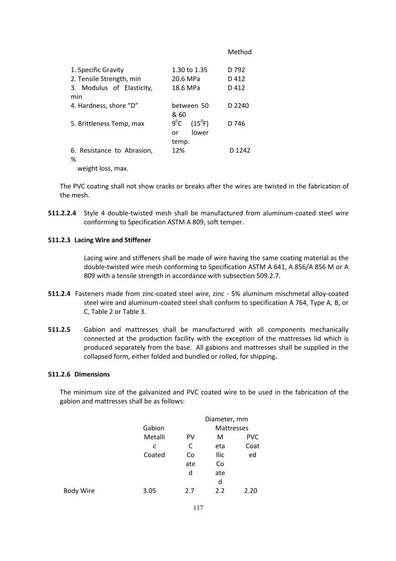
117
Method 1. Specific Gravity 1.30 to 1.35 D 792 2. Tensile Strength, min 20.6 MPa D 412 3. Modulus of Elasticity, min
18.6 MPa D 412
4. Hardness, shore “D” between 50 & 60
D 2240
5. Brittleness Temp, max 90C (150F) or lower temp.
D 746
6. Resistance to Abrasion, % weight loss, max.
12% D 1242
The PVC coating shall not show cracks or breaks after the wires are twisted in the fabrication of the mesh.
511.2.2.4 Style 4 double-twisted mesh shall be manufactured from aluminum-coated steel wire conforming to Specification ASTM A 809, soft temper.
511.2.3 Lacing Wire and Stiffener
Lacing wire and stiffeners shall be made of wire having the same coating material as the double-twisted wire mesh conforming to Specification ASTM A 641, A 856/A 856 M or A 809 with a tensile strength in accordance with subsection 509.2.7.
511.2.4 Fasteners made from zinc-coated steel wire, zinc - 5% aluminum mischmetal alloy-coated
steel wire and aluminum-coated steel shall conform to specification A 764, Type A, B, or C, Table 2 or Table 3.
511.2.5 Gabion and mattresses shall be manufactured with all components mechanically
connected at the production facility with the exception of the mattresses lid which is produced separately from the base. All gabions and mattresses shall be supplied in the collapsed form, either folded and bundled or rolled, for shipping.
511.2.6 Dimensions
The minimum size of the galvanized and PVC coated wire to be used in the fabrication of the gabion and mattresses shall be as follows: Diameter, mm
Gabion Mattresses Metalli
c Coated
PVC
Coated
Metallic Coated
PVC Coated
Body Wire 3.05 2.7 2.2 2.20

118
Selvedge or Perimeter Wire Tying and Connecting Wire
3.80 2.20
0 3.40 2.20
0 2.70 2.20
2.70 2.20
Diameter Tolerances for Galvanized Wire to be used in the fabrication of gabion and mattress
shall be .10. The nominal and the minimum thickness of PVC coating shall be 0.50 mm and 0.38 mm, respectively.
511.2.7 Mechanical Properties
Tensile Strength – The tensile strength of Zinc-coated wire used in the fabrication of gabion and mattresses when tested in accordance with Test Methods ASTM A 370, shall be as follows:
Strength, max, Mpa Gabion Mattresses Body Wire 485 515 Selvedge or Perimeter Wire
485 485
Tying and Connecting Wire
515 515
511.2.8 Weight of Coating The minimum weight of zinc per unit area of uncoated wire surface shall be in accordance with ASTM A 975 or as follows:
Wire Diameter, mm Class 3 or A Coating, g/m2, ASTM A 641
Over 1.90 to 2.30 220 Over 2.30 to 2.70 230 Over 2.70 to 3.10 240 Over 3.10 to 3.50 260 Over 3.50 to 3.90 270
511.2. 9 Rock Fill Rock used in the gabions and mattresses shall consist of hard, durable rock pieces that will not deteriorate when submerged in water or exposed to severe weather conditions. Rock pieces shall be generally uniformly graded in sizes ranging from 100 mm to 200 mm. Filled gabions shall have a minimum density of 1,400 kg/m3. Voids shall be evenly distributed. No rock size shall exceed 2/3 the mattress depth and at least 85% by weight of the stone shall have a size greater than 80 mm. No stones shall be able to pass through the mesh. The rock shall meet the requirements of AASHTO M 63 except that the sodium sulphate soundness loss shall not exceed 9% after 5 cycles.

119
511.2.10 Filter Fabric Filter cloth shall consist of 70% polypropylene and 30% polyethylene.
511.3 Construction Requirements
511.3.1 Fabrication
1. Gabions and mattresses shall be in the form of rectangular baskets of the required dimensions and shall be manufactured from wire as specified in Subsection 509.2.2. Gabions shall be made of steel wire double twisted forming a uniform hexagonal mesh type 8 x 10 having a nominal mesh openings of 83 by 114 mm. Mattresses shall be made of steel wire double twisted forming a uniform hexagonal mesh type 6 x 8 having a nominal mesh openings of 64 by 83 mm. Tolerances on the hexagonal, double-
twisted wire mesh opening shall not exceed 10% on the nominal dimension D values, 64 mm for mattresses and 83 mm for gabions. The edges shall be formed into a securely connected selvedge adequate to prevent raveling.
Individual basket ties and connections shall be made by using a quantity of wire not less than 8% of the weight of each basket.
2. When the gabion length exceeds its width, it shall have securely tied diaphragms
connected at all edges to form individual cells of equal length and width. Gabions shall be fabricated in such a manner that the sides, ends, lids and diaphragms can be assembled at the construction site into rectangular baskets of the specified sizes. Gabions shall be of single unit construction, base, lids, ends and sides shall be either woven into a single unit or one edge of these members connected to the base section of the gabion in such a manner that the strength and flexibility at the point of connection is at least equal to that of the mesh. The gabion shall be equally divided by diaphragms, placed at not more than 1.0 m intervals, and of the same mesh and gauge as the body of the gabions, into cells the length of which does not exceed the horizontal width. The gabion shall be furnished with the necessary diaphragms secured in proper position on the base in such a manner that no additional tying at this junction will be necessary.
3. Four cross-connecting wires shall be provided in each cell having a height of one half
the width or less, and eight cross-connecting wires shall be provided in each cell having a height greater than one half the width.
All perimeter edge of the mesh forming the gabion shall be securely selvedged so that the joints, by tying the selvedges, have at least the same strength as the body of the mesh. Selvedge wire used through all the edges (perimeter wire) shall not be less than 3.80 mm diameter and shall meet the same specifications as the wire mesh.

120
511.3.2 Assembly and Construction:
1. Gabions shall be installed in a workmanlike manner. The gabions shall be placed on a smooth foundation. Final line and grade shall be approved by the Engineer.
Each gabion unit shall be assembled by binding together all vertical edges with wire ties on approximately 152 mm (6 inches) spacing or by a continuous piece of connecting wire stitched around the vertical edges with a coil every 102 mm ( 4 inches). Empty gabion units shall be set to line and grade as shown on the Plans or as described by the Engineer. Wire ties or connecting wires shall be used to join the units together in the same manner as described above for assembling. Internal tie wires shall be uniformly spaced and securely fastened in each cell of the structure.
A standard fence stretcher, chain fall, or iron rod may be used to stretch the wire
baskets and hold alignment. 2. When possible the subgrade of the mattress and gabion shall be properly compacted
to a depth of 150 mm. The Contractor shall consider the cost of subgrade preparation in the unit prices. Filter fabric as beds of gabions and mattresses forming the structure shall be suitably leveled and shall be securely connected along the complete length of all contact edges by means of the above specified tying and connecting wire.
3. Before the filling material is placed, the gabions and mattresses shall be carefully
selected for uniformity of size, and the pieces shall be handplaced to provide a neat appearance as approved by the Engineer. The gabions shall be filled with stone carefully placed by hand or machine to assure alignment and avoid bulges with a minimum voids. Alternate placing of rock and connection wires shall be performed until the gabion is filled. After a gabion has been filled, the lid shall be bent over until it meets the sides and edges. The lid shall then be secured to the sides, ends and diaphragms with the wire ties or connecting wire in the manner described for assembling. The vertical joints of gabions and mattress baskets shall be staggered as in running bond in brickwork.
4. The cells in any row shall be filled in stage so that local deformation may be avoided. That is at no time shall the cell be filled to a depth exceeding 30 cm more than the adjoining cell.
5. Filter fabric shall be placed between earth surface and gabion or mattress structures.
Filter fabric shall be rolled out into a flat non-rutted surface free from sharp objects, weighing down the edges. Construction equipment shall not be allowed into unprotected fabric. Jointing is normally affected by overlapping not less than 300 mm, but it is preferable to joint by sewing or industrial stapling. Joint edges should be facing downwards to avoid protruding through the surface material.

121
511.4 Method of Measurement The quantities to be paid for shall be the number of cubic meter of gabions and mattresses and the area of filter cloth completed and accepted.
511.5 Basis of Payment Quantities determined as provided above shall be paid for at the appropriate contract unit price per unit of measurement for the Pay Item shown in the Bid Schedule, which price and payment shall constitute full compensation for all necessary excavation, subgrade preparation, for furnishing, placing wire baskets and fill materials and for all labor, equipment accessories, tools, and incidentals necessary to complete the Item.
Payment will be made under:
Pay Item Number
Description Unit of Measurement
511 (1) Gabions Cubic Meter 511 (2) Mattresses Cubic Meter 511 (3) Filter Cloth Square Meter

122
ITEM 508 – HAND-LAID ROCK EMBANKMENT
508.1 Description
This Item shall consist of hand-laid rock embankment, as designated in the Bid Schedule, constructed in accordance with this Specification and in conformity with the lines and grades shown on the Plans or established by the Engineer.
508.2 Material Requirements Stones shall be sound and durable and furnished in a well-balanced ranged of sizes meeting the requirements herein. Unless otherwise provided by the Plans or Special provisions, all stones shall be more than 0.015 cubic meter in volume and not less than 75 percent of the total volume of rock embankment and shall consist of stones 0.03 cubic meter in volume. Stones obtained from excavation performed under this contract may be used. Adobe stone shall not be used, unless otherwise specified.
508.3 Construction Requirements Sufficient excavation shall be made to expose a foundation bed that is satisfactory to the Engineer. The stones shall be founded on this bed and laid to the lines and dimensions required. Stones shall be laid flat and securely placed with broken joint lines. The larger stones shall generally be located in the lower part of the structure and voids shall be eliminated to the extent possible. Spalls smaller than the minimum stone size specified in Section 506.2, Material Requirements, shall be used to check the larger stones solidly in position and to substantially fill voids between the major stones as laid in the embankment. The exposed face of the rock mass shall be reasonably uniform, with no projections of more than 150 mm, beyond the neat lines shown on the Plans or as directed by the Engineer. Backfill adjacent to the hand-laid rock embankment shall be filled entirely with acceptable material coming from excavation items and compacted.
508.4 Method of Measurement The quantity to be paid for will be the number of cubic meter of hand-laid rock embankment measured in place, completed and accepted.
508.5 Basis of Payment The quantity determined, as provided in Section 508.4, Method of Measurement , will be paid for at the contract price per cubic meter for Hand-Laid Rock Embankment, which price and payment shall constitute full compensation for furnishing, selecting, and transporting stones, for placing stones by hand, for backfilling, and for all labor, equipment, tools and incidentals necessary to complete the Item including foundation excavation.

123
Payment will be made under:
Pay Item Number
Description Unit of Measurement
508 Hand-Laid Rock
Embankment Cubic Meter

124
Section VII. Drawings

1 : 100 mtrs
SCALE:
L A Y O U T P L A N
CENTERLINE PROFIIE OF SEA PORTSCALE:
1 : 100 mtrs
5.00
1 : 30 mtrs
SCALE:
CROSS SECTION/DETAIL OF STAIRS
WITH 10mmØ TEMP. BAR SPACED @ 0.30m O.C.12mmØ LONG. DRSB SPACED @ 0.30m O.C.
0.50
0.55
0.15
0.30
2.10
0.30
1 : 40 mtrs
SCALE:
TYPICAL SECTION OF WHARF
4.00
0.15 m. THK. PCCP
Sea Bed
EXIS
TING
WHA
RF
PROP
OSED
0.15
m. T
HK. P
CCP
5.00
0.30 m. THK. AGGREGATE BASE COURSE0.15 m. THK. PCCP
N.G.L.
G A B I O N
PROPOSED STAIRLANDINGSEE DETAIL
G A B I O N
ISOMETRIC DETAIL OF GABION WIRE CAGESCALE:
1 : 25 mtrs
1 : 3 mtrs
SCALE:
DETAIL OF MESH
0.08
0.10
SEA BED
-
JMG/YAAC
JCC
--/--/--PROJECT SCOPE:
Total Sheet No.:
Sheet No.:
LOCATION :
PROJECT NAME :
BURGOS PORT DEVELOPMENT PROJECT (C.Y. 2014)
/
A S S H O W N
Sheet Content: Revisions:
Director, Project Development Service
Checked by:
DEO LEO N. MANALO
Approved by:
Reviewed by:
Assistant Secretary for Project DevelopmentJAIME RAPHAEL C. FELICIANO
Undersecretary for PlanningRENE K. LIMCAOCO
PRC NO. VALID UNTIL
PTR NO. ISSUED ON
ISSUED AT TIN
REPUBLIC OF THE PHILIPPINES
DEPARTMENT OF TRANSPORTATION AND
COMMUNICATIONS
PROJECT DEVELOPMENT SERVICE
UNIT 83, THE COLUMBIA TOWER, BRGY. WACK WACK,
ORTIGAS AVENUE, MANDALUYONG CITY 1555
P
S
R
A
F
N
A
R
T
M
T
O
T
N
E
O
O
C
D
N
A
T
R
A
N
O
I
T
P
C
I
N
U
A
E
DS
N
O
I
T
M
M
The copyright of this drawing remains the property of the Department of Transportation and Communications whose permission must be obtained before any use of it can be made.
DRAWN BY:
CHECKED BY:
DATE DRAWN:
DATE PRINTED:
DATE APPROVED:SCALE : AS SHOWN
Construction of Causeway and Back-up Area
Brgy. Burgos, Daram, Leyte
--/--/--
ELEV
. +2.8
0. m.
MLLW = +0.35 meters
GABIONS
CLASS III ROCKS (5-15KGS/PC)
VICINITY MAPSITE

126
Section VIII. Bill of Quantities

127
BID ANNEX 5
PROPOSAL SCHEDULE
PROJECT TITLE : CONSTRUCTION OF BRGY. BURGOS WHARF
Widening of Existing Causeway and Construction of Wharf
LOCATION : Brgy. Burgos, Daram, Samar
(14.1) (14.2) (14.3) (14.4) (14.5) (14.6)
ITEM ITEM OF WORK UNIT QUANTITY UNIT BID AMOUNT
NO. COST
201 Aggregate base Course (0.30m. thick) cu.m. 71.00
311 P.C.C.P (0.15m. thick) sq.m 234.00
405 Concrete Works - 3,500 psi cu.m 42.00
511 Gabions pcs. 738.00
508 Class III Rocks cu.m 1,708.00
SPL-1 Demolition and Clearing for Gabions l.s. 1.00
SPL-2 TEMPORARY FACILITIES l.s. 1.00
***nothing follows***
TOTAL PROJECT COST
AMOUNT IN WORDS:
Submitted By :
(Name of Firm)
Signing Authority :
(Printed Name and Signature)
Designation :
Date :

128
Section IX. Bidding Forms
TABLE OF CONTENTS
Bid Form .............................................................................................................................................. 129
Form of Contract Agreement .............................................................................................................. 131
Omnibus Sworn Statement ................................................................................................................. 133
Bid Securing Declaration ..................................................................................................................... 135

129
Bid Form
Date: _________________________
IAEB1 No: ______________________
To: [name and address of PROCURING ENTITY]
Address: [insert address]
We, the undersigned, declare that:
(a) We have examined and have no reservation to the Bidding Documents, including Addenda, for the Contract [insert name of contract];
(b) We offer to execute the Works for this Contract in accordance with the Bid and Bid Data Sheet, General and Special Conditions of Contract accompanying this Bid;
The total price of our Bid, excluding any discounts offered in item (d) below is: [insert information];
The discounts offered and the methodology for their application are: [insert information];
(c) Our Bid shall be valid for a period of [insert number] days from the date fixed for the Bid submission deadline in accordance with the Bidding Documents, and it shall remain binding upon us and may be accepted at any time before the expiration of that period;
(d) If our Bid is accepted, we commit to obtain a Performance Security in the amount of [insert percentage amount] percent of the Contract Price for the due performance of the Contract;
(e) Our firm, including any subcontractors or suppliers for any part of the Contract, have nationalities from the following eligible countries: [insert information];
(f) We are not participating, as Bidders, in more than one Bid in this bidding process, other than alternative offers in accordance with the Bidding Documents;
(g) Our firm, its affiliates or subsidiaries, including any subcontractors or suppliers for any part of the Contract, has not been declared ineligible by the Funding Source;
(h) We understand that this Bid, together with your written acceptance thereof included in your notification of award, shall constitute a binding contract between us, until a formal Contract is prepared and executed; and
(i) We understand that you are not bound to accept the Lowest Evaluated Bid or any other Bid that you may receive.
1 If ADB, JICA and WB funded projects, use IFB.

130
Name:
In the capacity of:
Signed:
Duly authorized to sign the Bid for and on behalf of:
Date: ___________

131
Form of Contract Agreement
THIS AGREEMENT, made this [insert date] day of [insert month], [insert year] between [name and address of PROCURING ENTITY] (hereinafter called the“Entity”) and [name and address of Contractor] (hereinafter called the “Contractor”).
WHEREAS, the Entity is desirous that the Contractor execute [name and identification number of contract] (hereinafter called “the Works”) and the Entity has accepted the Bid for [insert the amount in specified currency in numbers and words] by the Contractor for the execution and completion of such Works and the remedying of any defects therein.
NOW THIS AGREEMENT WITNESSETH AS FOLLOWS:
1. In this Agreement, words and expressions shall have the same meanings as are respectively assigned to them in the Conditions of Contract hereinafter referred to.
2. The following documents shall be attached, deemed to form, and be read and construed as part of this Agreement, to wit:
(a) General and Special Conditions of Contract;
(b) Drawings/Plans;
(c) Specifications;
(d) Invitation to Apply for Eligibility and to Bid;
(e) Instructions to Bidders;
(f) Bid Data Sheet;
(g) Addenda and/or Supplemental/Bid Bulletins, if any;
(h) Bid form, including all the documents/statements contained in the Bidder’s bidding envelopes, as annexes;
(i) Eligibility requirements, documents and/or statements;
(j) Performance Security;
(k) Credit line issued by a licensed bank, if any;
(l) Notice of Award of Contract and the Bidder’s conforme thereto;
(m) Other contract documents that may be required by existing laws and/or the Entity.
3. In consideration of the payments to be made by the Entity to the Contractor as hereinafter mentioned, the Contractor hereby covenants with the Entity to execute and complete the Works and remedy any defects therein in conformity with the provisions of this Contract in all respects.
4. The Entity hereby covenants to pay the Contractor in consideration of the execution and completion of the Works and the remedying of defects wherein, the Contract Price or such other sum as may become payable under the provisions of this Contract at the times and in the manner prescribed by this Contract.

132
IN WITNESS whereof the parties thereto have caused this Agreement to be executed the day and year first before written.
Signed, sealed, delivered by the (for the Entity)
Signed, sealed, delivered by the (for the Contractor).
Binding Signature of PROCURING ENTITY
________________________________________________
Binding Signature of Contractor
_____________________________________________
[Addendum showing the corrections, if any, made during the Bid evaluation should be attached with this agreement]

133
Omnibus Sworn Statement
REPUBLIC OF THE PHILIPPINES ) CITY/MUNICIPALITY OF ______ ) S.S.
A F F I D A V I T
I, [Name of Affiant], of legal age, [Civil Status], [Nationality], and residing at [Address of Affiant], after having been duly sworn in accordance with law, do hereby depose and state that:
1. Select one, delete the other: If a sole proprietorship: I am the sole proprietor of [Name of Bidder] with office address at [address of Bidder]; If a partnership, corporation, cooperative, or joint venture: I am the duly authorized and designated representative of [Name of Bidder] with office address at [address of Bidder];
2. Select one, delete the other: If a sole proprietorship: As the owner and sole proprietor of [Name of Bidder], I have full power and authority to do, execute and perform any and all acts necessary to represent it in the bidding for [Name of the Project] of the [Name of the Procuring Entity]; If a partnership, corporation, cooperative, or joint venture: I am granted full power and authority to do, execute and perform any and all acts necessary and/or to represent the [Name of Bidder] in the bidding as shown in the attached [state title of attached document showing proof of authorization (e.g., duly notarized Secretary’s Certificate issued by the corporation or the members of the joint venture)];
3. [Name of Bidder] is not “blacklisted” or barred from bidding by the Government of the Philippines or any of its agencies, offices, corporations, or Local Government Units, foreign government/foreign or international financing institution whose blacklisting rules have been recognized by the Government Procurement Policy Board;
4. Each of the documents submitted in satisfaction of the bidding requirements is an authentic copy of the original, complete, and all statements and information provided therein are true and correct;
5. [Name of Bidder] is authorizing the Head of the Procuring Entity or its duly authorized representative(s) to verify all the documents submitted;
6. Select one, delete the rest:

134
If a sole proprietorship: I am not related to the Head of the Procuring Entity, members of the Bids and Awards Committee (BAC), the Technical Working Group, and the BAC Secretariat, the head of the Project Management Office or the end-user unit, and the project consultants by consanguinity or affinity up to the third civil degree; If a partnership or cooperative: None of the officers and members of [Name of Bidder] is related to the Head of the Procuring Entity, members of the Bids and Awards Committee (BAC), the Technical Working Group, and the BAC Secretariat, the head of the Project Management Office or the end-user unit, and the project consultants by consanguinity or affinity up to the third civil degree; If a corporation or joint venture: None of the officers, directors, and controlling stockholders of [Name of Bidder] is related to the Head of the Procuring Entity, members of the Bids and Awards Committee (BAC), the Technical Working Group, and the BAC Secretariat, the head of the Project Management Office or the end-user unit, and the project consultants by consanguinity or affinity up to the third civil degree;
7. [Name of Bidder] complies with existing labor laws and standards; and
8. [Name of Bidder] is aware of and has undertaken the following responsibilities as a Bidder: a) Carefully examine all of the Bidding Documents;
b) Acknowledge all conditions, local or otherwise, affecting the implementation of the
Contract;
c) Made an estimate of the facilities available and needed for the contract to be bid, if any; and
d) Inquire or secure Supplemental/Bid Bulletin(s) issued for the [Name of the Project].
9. [Name of Bidder] did not give or pay directly or indirectly, any commission, amount, fee, or any form of consideration, pecuniary or otherwise, to any person or official, personnel or representative of the government in relation to any procurement project or activity.
IN WITNESS WHEREOF, I have hereunto set my hand this __ day of ___, 20__ at ____________,
Philippines. _____________________________________ Bidder’s Representative/Authorized Signatory
[JURAT]
* This form will not apply for WB funded projects.

135
Bid-Securing Declaration
REPUBLIC OF THE PHILIPPINES ) CITY OF __________________ ) S.S. x-----------------------------------------------x BID-SECURING DECLARATION
Invitation to Bid/Request for Expression of Interest No.6 : [Insert reference number]
To: [Insert name and address of the Procuring Entity]
I/We7, the undersigned, declare that:
1. I/We understand that, according to your conditions, bids must be supported by a Bid
Security, which may be in the form of a Bid-Securing Declaration.
2. I/We accept that: (a) I/we will be automatically disqualified from bidding for any contract with any procuring entity for a period of two (2) years upon receipt of your Blacklisting Order; and, (b) I/we will pay the applicable fine provided under Section 6
of the Guidelines on the Use of Bid Securing Declaration8, if I/we have committed
any of the following actions:
i. Withdrawn my/our Bid during the period of bid validity required in the Bidding Documents; or
ii. Fail of refuse to accept the award and enter into contract or perform any and all acts necessary to the execution of the Contract, in accordance with the Bidding Documents after having been notified of your acceptance of our Bid during the period of bid validity.
3. I/We understand that this Bid-Securing Declaration shall cease to be valid on the
following circumstances:
(a) Upon expiration of the bid validity period, or any extension thereof pursuant to your request;
(b) I am/we are declared ineligible or post-disqualified upon receipt of your notice to such effect, and (i) I/we failed to timely file a request for reconsideration or (ii) I/we filed a waiver to avail of said right;
_________________________

136
6 Select one and delete the other.
7 Select one and delete the other. Adopt same instruction for similar terms throughout the document.
8 Issued by the GPPB through GPPB Resolution 03-2012 on 27 January 2012
(c) I am/we are declared as the bidder with the Lowest Calculated and
Responsive Bid/Highest Rated and Responsive Bid9, and I/we have furnished
the performance security and signed the Contract.
IN WITNESS WHEREOF, I/We have hereunto set my/our hand/s this _____ day of [month] [year] at [place of execution].
[Insert NAME OF BIDDER’S AUTHORIZED REPRESENTATIVE] [Insert signatory’s legal capacity]
Affiant
SUBSCRIBED AND SWORN to before me this _____ day of [month] [year] at
[place of execution], Philippines. Affiant’s is/are personally known to me and was/were identified by me through competent evidence of identity as defined in the 2004 Rules on Notarial Practice (A.M. No. 02-8-13-SC). Affiant/s exhibited to me his/her [insert type of government identification card used], with his/her photograph and signature appearing thereon, with no. _________ and his/her Community Tax Certificate No. ______________ issued on ______________ at ___________.
Witness my hand and seal this ________ day of [month] [year].
NAME OF NOTARY PUBLIC Serial No. of Commission
_____________ Notary Public for _______ until
_______ Roll of Attorneys No. ____
PTR No. ___[date issued], [place issued] IBP No. ___[date issued], [place
issued]
Doc. No. __________
Page No. __________
Book No. __________
Series of __________

137
_________________________ 9
Select one and delete the other.

138

139

140

141

142
