section page no. introduction 1 purpose of · pdf filechassis jacking point 12 ... warranty...
TRANSCRIPT
CONTENTSSection Page No.INTRODUCTION 1PURPOSE OF MACHINE 2MACHINE DIMENSIONS & SPECIFICATIONS 2PARTS LOCATION DIAGRAMS 3 & 4SAFE WORKING 5
Operator’s Personal Protective Equipment Required 5Basic Woodchipping Safety 5General Safety Matters - Do’s and Don’ts 6Noise Test 7
OPERATING INSTRUCTIONS 8Delivery 8Operator’s Personal Protective Equipment Required 8Manual Controls 8Crawler Track Controls 9Auto Controls 9Emergency Stopping 9Daily Checks Before Starting 10Engine Controls 10Starting the Engine 10Controlling the Engine Speed 10Stopping the Engine 10Fuel Level Indicator 10Before Using the Chipper 11Starting to Chip 11Chipping 11Discharge Controls 12Blockages 12Removing the Funnel 12Chassis Jacking Point 12
SERVICE INSTRUCTIONS 13Service Schedule 14Safe Maintenance 15Engine Manufacturer’s Handbook 15Spares 15Battery Removal and Maintenance 15Greasing Rotor Bearings 16Safe Lifting & Securing down of the Chipper 16Copper Ease Safety Information 17Battery Safety Information 17Change Hydraulic Oil and Filter 19Check Fittings 19Check Hoses 19Change Blades 20Tension Belts 21Grease the Roller Spline and Bearing 21Grease the Roller Box Slides 22Track Base Maintenance 22Lubricate Variable Track Base Slides 22Replace Oil in Track Drive Unit 23Draining the Oil in the Track Drive Unit 23Reduction Unit Oil Types 23Checking the Rubber Tracks 23Checking Track Tension 24Track Loosening / Tightening Procedures 24Removing the Rubber Tracks 25Installing the Rubber Tracks 25Checking Sprocket Wear 25
WARRANTY STATEMENT 26EC DECLARATION OF CONFORMITY CERTIFICATE 27IDENTIFICATION PLATES 28DECALS 29 & 30ELECTRICAL DETAILS 31CIRCUIT DIAGRAM 32HYDRAULIC LAYOUT 33PARTS LISTS 34 - 56
30th Aug 2011

TIMBERWOLF TW 150VTR 1
Thank you for choosing this Timberwolf brushwood chipper. Timberwolf chippers are
designed to give safe and dependable service if operated according to the instructions.
Before using your new chipper, please take time to
read this manual which contains
IMPORTANT HEALTH AND SAFETY INFORMATION
and explains the chipper controls. Failure to do so could result in:
- personal injury
- equipment damage
- damage to property
- a member of the general public becoming injured
This manual covers the operation and maintenance of the Timberwolf TW 150VTR. All
information in this manual is based on the latest product information available at the
time.
All the information you need to operate the machine safely and effectively is contained
within pages 3 to 12. Ensure that all operators are properly trained for operating this
machine, especially with regard to safe working practices.
Timberwolf's policy of constantly improving their products may involve major or minor
changes to the chippers or their accessories. Timberwolf reserves the right to make
changes at any time without notice and without incurring any obligation.
Due to improvements in design and performance during production there may be, in
some cases, minor discrepancies between the actual chipper and the text in this
manual.
The manual should be considered a permanent part of the
machine and should remain with it if the machine is resold.
CAUTION or WARNINGBe aware of this symbol and where shown,
carefully follow the instructions.
This caution symbol indicates important safety messages in this manual. When
you see this symbol, be alert to the possibility of injury to yourself or others, and
carefully read the message that follows.
Always follow safe operating and maintenance practices
INTRODUCTION
!

The Timberwolf TW 150VTR brushwood chipper is designed to chip solid wood material up to 150
mm in diameter. It is capable of chipping up to 4 tonnes of brushwood per hour.
PURPOSE OF MACHINE
TIMBERWOLF TW 150VTR SPECIFICATION
TIMBERWOLF TW 150VTR 2
Serial No. LocationThe serial number can be
found on the information
plate fixed to the chassis
beam.
1575 m
m
DIMENSIONS
2300 m
m
2775 mm
Width w
ith
funnel
1265 mm
TIMBERWOLF
Width w
ith
funnel
1265 mm
1588 m
m2300 m
m
3122 mm (2479 with feed tray folded).
TW 150VTR WITH
LOW FUNNEL
TW 150VTR WITH
HIGH FUNNEL
Engine type Kubota 4-cylinder dieselMaximum power 26kW (35hp)Cooling method Water cooledOverall weight 1080kg Starting method ElectricRoller feed Twin series hydraulic motors
Maximum diameter material 150 mm (6")Fuel capacity 18 litresHydraulic oil capacity 15 litresMaterial processing capacity 4 tonnes/hrFuel type Diesel
TIMBERWOLF
Variable
Track Width
700-1100 mm
Variable
Track Width
700-1100 mm
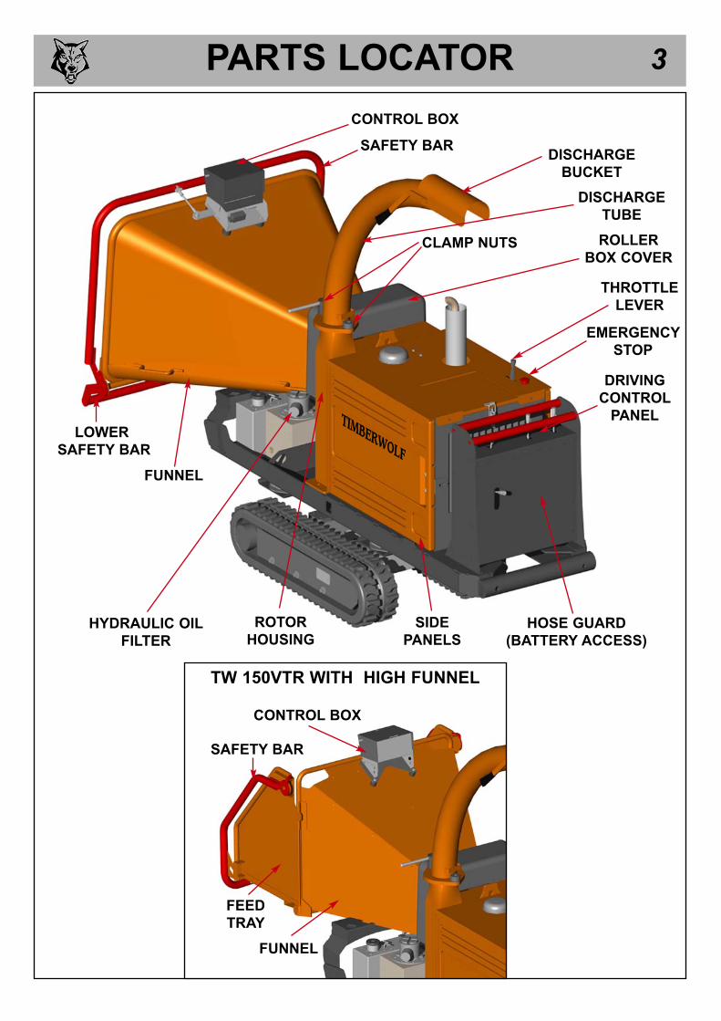
PARTS LOCATOR 3
SAFETY BAR
FUNNEL
DISCHARGE
BUCKET
DISCHARGE
TUBE
CLAMP NUTS
CONTROL BOX
HOSE GUARD
(BATTERY ACCESS)
ROLLER
BOX COVER
SIDE
PANELSHYDRAULIC OIL
FILTER
ROTOR
HOUSING
THROTTLE
LEVER
EMERGENCY
STOP
DRIVING
CONTROL
PANELTIMBERWOLF
TW 150VTR WITH HIGH FUNNEL
FUNNEL
FEED
TRAY
SAFETY BAR
CONTROL BOX
LOWER
SAFETY BAR

PARTS LOCATOR 4
BATTERY
FUEL TANK
ENGINE
BLOCK
ROTOR
FAN
ROTOR PULLEY
DRIVE
PULLEY
BELT
TENSION
ADJUSTER
FUEL PUMP
EXHAUST
FUEL
FILTER
DIP STICK
OIL
FILTER
ALTERNATOR
CONTROL
PANEL
STARTER
MOTOR
RADIATOR
AIR FILTER
HYDRAULIC
PUMP
DIRECTIONAL
CONTROL VALVE
HYDRAULIC
OIL TANK
ROLLER BOX
TOP SLIDE
RESERVETANK

SAFE WORKING 5
BASIC WOODCHIPPING SAFETY
The operator should be aware of the following points:
MAINTAIN A SAFETY EXCLUSION ZONE around the chipper of at least 10 metres for the
general public or employees without adequate protection. Use hazard tape to identify this
working area and keep it clear from debris build up. Chips should be ejected away from any
area the general public have access to.
HAZARDOUS MATERIAL - Some species of trees and bushes are poisonous. The chipping
action can produce vapour, spray and dust that can irritate the skin. This may lead to
respiratory problems or even cause serious poisoning. Check the material to be chipped before
you start. Avoid confined spaces and use a facemask if necessary.
BE AWARE when the chipper is processing material that is an awkward shape. The material
can move from side to side in the funnel with great force. If the material extends beyond the
funnel, the brash may push you to one side causing danger. Badly twisted brash should be
trimmed before being chipped to avoid thrashing in the feed funnel.
BE AWARE that the chipper can eject chips out of the feed funnel with considerable force.
Always wear full head and face protection.
ALWAYS work on the side of the machine furthest from any local danger, e.g. not road side.
WARNING
The chipper will feed material through on its own. To do this, it relies on sharpblades on the chipper rotor. To keep the blades sharp, only feed the machinewith clean brushwood. DO NOT put muddy/dirty wood, roots, potted plants,bricks, stones or metal into the chipper.
!!
OPERATOR'S PERSONAL PROTECTIVE EQUIPMENT REQUIRED
Chainsaw safety helmet
fitted with mesh visor and
recommended ear defenders
to the appropriate
specifications.
Work gloves with
elasticated wrist.
Close fitting heavy-duty
non-snag clothing.
Face mask if
appropriate.
DO NOTwear rings, bracelets,watches, jewellery or anyother items that could becaught in the material anddraw you into the chipper.
Steel toe cap safety boots.

SAFE WORKING 6
WARNINGNEVER LEAVE CHIPPER ON A SLOPE UNATTENDED.! !
GENERAL SAFETY MATTERS
DO NOT operate chipper unless available light issufficient to see clearly.
DO NOT use or attempt to start the chipperwithout the feed funnel, guards and dischargeunit securely in place.
DO NOT stand directly in front of the feed funnelwhen using the chipper. Stand to one side.
DO NOT allow -
DO NOT smoke when refuelling.
DO NOT let anyone who has not receivedinstruction operate the machine.
DO NOT climb or ride on the machine at any time.
DO NOT handle material that is partially engagedin the machine.
DO NOT touch any exposed wiring whilemachine is running.
DO NOT use the chipper inside buildings.
- to enter the machine, as damage is likely.
ALWAYS stop the chipper engine before makingany adjustments, refuelling or cleaning.
ALWAYS check rotor has stopped rotating andremove chipper ignition key before maintenanceof any kind, or whenever the machine is to be leftunattended.
ALWAYS check the machine is well supportedand cannot move.
ALWAYS operate the chipper with the engine setto maximum speed when chipping.
ALWAYS check (visually) for fluid leaks.
ALWAYS take regular breaks. Wearing personalprotective equipment for long periods can betiring and hot.
ALWAYS keep hands, feet and clothing out offeed opening, discharge and moving parts.
ALWAYS use the next piece of material or a pushstick to push in short pieces. Under nocircumstances should you reach into the funnel.
ALWAYS keep the operating area clear of people,animals and children.
ALWAYS keep the operating area clear fromdebris build up.
ALWAYS keep clear of the chip discharge tube.Foreign objects may be ejected with great force.
ALWAYS ensure protective guarding is in placebefore commencing work. Failure to do so mayresult in personal injury or loss of life.
ALWAYS operate the chipper in a well ventilatedarea - exhaust fumes are dangerous.
!D O ’ S A N D D O N ’ T S
BRICKS STRING CLOTH PLASTIC STONES
METAL GLASS RUBBER ROOTS BEDDINGPLANTS
�
�

SAFE WORKING
MACHINE:
NOTES:
TW 150VTR
Tested Chipping 120 mm x 120 mm Corsican Pine
1.5m in length
NOISE TEST
7
Noise levels above 80dB (A) will be experienced at the working position. Wear ear protectionat all times to prevent possible damage to hearing. All persons within a 4 metre radius mustalso wear good quality ear protection.
93.8 dB95.3 dB
97.9 dB96.3 dB
R= 4 metres
Guaranteed Sound Power: 119dB (A)
102.6 dB
96.8 dB
As required by Supply of Machinery (safety) regulations of 2008.
R= 10 metres
90.2
dB
Calc
ula
ted
90.2dBCalculated
90.2dBCalc
ulate
d

OPERATING INSTRUCTIONS 8DELIVERY
All Timberwolf 150VTR machines have a full pre - delivery inspection before leaving the factory and areready to use. Read and understand this instruction manual before attempting to operate the chipper. Inparticular, read pages 5-7 which contain important health and safety information and advice.
OPERATOR’S PERSONAL PROTECTIVE EQUIPMENT REQUIRED
CHAINSAW safety helmet fitted with visor and
recommended ear defenders to an appropriate
specification.
HEAVY-DUTY Work gloves with elasticated wrist.
CLOSE - FITTING heavy-duty non-snag clothing.
SAFETY footwear.
FACE MASK (if appropriate).
MANUAL CONTROLS
GREEN
FORWARD
FEED
PANEL
BLUE
REVERSE
FEED
PANEL
RED STOP FEED -
EMERGENCY STOP BUTTON
RED SAFETY BAR
See page 5 for more detailed information.
PU
SH TO STOP
PU
LLTO RES
ET
Roller control box - is the control box above the feed opening of the chipper funnel. Its function is to controlthe feed rollers. The feed rollers draw material into the machine. It does not control the main rotor.
RED SAFETY BAR = This is the large red bar that surrounds the sides and top of the feed funnel(sides and bottom on high funnel). The bar is spring loaded and connected to a switch that willinterrupt the power to the rollers. The switch is designed so that it only activates if the bar is pushed(pushed or pulled...low funnel only) to the limit of its travel. The rollers stop instantly, but can be madeto turn again by pressing either the GREEN FEED or BLUE REVERSE control buttons.
LOW SAFETY BAR = An additional safety bar is located along the bottom of the low funnel. This islinked directly to the main bar, and will stop the rollers if pushed only. Pulling this bar will only moveit into its ‘stowed’ (up) position.
GREEN BUTTON = Forward feed - Push the button once - this activates the rollers and will allow youto start chipping (if the rotor speed is high enough).
RED BUTTON = Emergency stop - This button stops the rollers from feeding. It overrides all otherbuttons or bars and will not allow the other buttons to function until it has been reset. Pull the button out toreset, the forward and reverse buttons will now function.
BLUE BUTTON = Reverse feed - allows you to back material out of the rollers. The rollers will onlyturn in reverse as long as you keep pressing the button. You do not have to press the STOP buttonbefore pressing the GREEN FEED button to recommence feeding. NOTE: This reverse function willwork even if the safety bar is pushed or pulled.
Do not rely on the red bar to keep the rollers stationary if it is
necessary to clear or touch the rollers. Always switch off the
machine and remove ignition key before approaching the rollers.
Control Panel Diagram

OPERATING INSTRUCTIONS 9CRAWLER TRACK CONTROLS
The chipper is designed to operate in either chipper or crawler mode, but not both at the same time.
CHIPPING MODEPower is available to the feed rollers. The cutting disc is rotating but the unit is stationary.
CRAWLER TRACK MODE Power is available to the crawler tracks. The cutting disc is rotating but the feed rollers are stationary.
To switch between modes, a lever is operated (see diagram below). This is locatedon the driving control panel (see parts locator on page 3). It is clearly marked.
When Track mode is selected the two track control valves may be operated. Thesehave direct control over the track relevant to each side of the machine. They areproportional valves, so increased movement will result in increased track speed.
Tracking may be done at either high or low engine speed. Manoeuvring themachine in tight spaces and while loading and unloading should be done with theengine on low speed.
For machines fitted with variable tracks, track width adjustment is only possible withthe track/chip control in the chip position. Track adjust handle is spring loaded to themiddle (see diagram, right). The more you move the handle, the more the tracksadjust. To move the tracks outward, move the track adjust handle up. To bringtracks inward, move the track adjust handle down.
TRACK
CHIP
AUTO CONTROLS
The engine management unit controls the feed rate of the material going into the chipping chamber. If theengine speed is below the predetermined level, the engine management unit will not allow the feed rollersto work in the forward feed direction, until the rotor speed rises above the predetermined level. At thispoint the feed rollers will start turning without warning. The reverse function will work at any speed.
There are three ways of stopping the TW 150VTR chipper in the event of an emergency.
STOPPING THE ROLLERS-Activating the red safety bar will stop the rollers immediately. To restart the rollers, just push thegreen forward button or blue reverse button.
-Pushing the red Emergency button on the roller control box will also stop the rollers immediately. Thebutton will stay in the “pushed in” position, and will require resetting (pulling out) before being able torestart the roller functions.
STOPPING THE ENGINEShould the entire machine need to be stopped in an emergency, the red button on top of the engineguard should be pushed. This will shut down the engine in the shortest possible time. The enginecannot be restarted until the button is pulled out and the main ignition switch is turned off to reset themachine.
EMERGENCY STOPPING
OUT
IN
3015
WARNINGNEVER LEAVE CHIPPER ON A SLOPE UNATTENDED.! !
NOTE: Ensure low safety bar onlow funnel is rotated into the‘stowed’ (up) position prior totracking to avoid damage to the bar.

OPERATING INSTRUCTIONS 10
LOCATE the machine on firm level ground.
CHECK machine is well supported and cannot move.
CHECK all guards are fitted and secure.
CHECK the discharge unit is in place and fastened securely.
CHECK discharge tube is pointing in a safe direction.
CHECK the feed funnel to ensure no objects are inside.
CHECK controls as described below.
CHECK (visually) for fluid leaks.
CHECK fuel and hydraulic oil levels.
For parts location see diagrams on pages 3 & 4.
DAILY CHECKS BEFORE STARTING
FUEL LEVEL INDICATOR
The fuel level can be seen through the wall of the fuel tank.
ENGINE CONTROLS
The engine controls are in two locations. The engine ignition is on the control panel in the centre ofthe machine, and the throttle lever is on the bonnet next to the engine emergency stop switch (seeparts locator on page 4).
ENSURE throttle lever is in the slow (tortoise) position.
INSERT key. Turn to heat.
HEATER LED comes on.
WAIT FOR HEATER LED TO GO OUT.
TURN key to engage starter motor.
RELEASE key once engine starts.
STARTING THE ENGINE
CONTROLLING ENGINE SPEED
The engine has two throttle settings, idle and fast. These are controlled by the
throttle lever on the bonnet. Moving the lever towards the ‘Hare’ on the pictogram
will increase engine speed while moving it towards the ‘Tortoise’ will decrease the
engine speed.
STOPPING THE ENGINE
MOVE the throttle lever to the ‘Tortoise’ to reduce the engine speed to idle.
LEAVE the engine running for 1 minute.
TURN the power switch to position 0. The engine should stop after a few seconds.
REMOVE the ignition key.
01
2
HOURS
0 0 0 0 0 0 0
HOURS COUNTER
STARTHEATOFF ON
01
2
Do not engage starter motor for more than 20seconds - allow one minute before attempting to start.Investigate reasons for failure to start.
When the emergency stop button is pressed it must be pulled out again and the ignition switchturned off to reset the machine before attempting to restart.

OPERATING INSTRUCTIONS 11
STARTING TO CHIP
WARNINGDo not use or attempt to start the chipper without the protective guardingand discharge unit securely in place. Failure to do so may result inpersonal injury or loss of life.
! !
CHIPPING
Wood up to 150 mm diameter can be fed into the feed funnel. Put the butt end in first and engage itwith the feed roller. The hydraulic feed rollers will pull the branch into the machine quite quickly. Largediameter material will have its feed rate automatically controlled by the engine management unit.
Sometimes a piece of wood that is a particularly awkward shape is too strong for the feed rollers tobreak. This will cause the top roller to either bounce up and down on the wood or both rollers to stall.If this occurs press the BLUE REVERSE button until the material has been released. Pull the materialout of the feed funnel and trim it so the chipper can handle it.
Both feed rollers should always turn at the same speed. If one or both rollers stop or suddenly slowdown it may be that a piece of wood has become stuck behind one of the rollers. If this occurs pressthe BLUE REVERSE button and hold for 2 seconds - then repress GREEN FEED button. This shouldenable the rollers to free the offending piece of material and continue rotation at the correct speed. Ifthe rollers continue to stall in the 'forward feed' or 'reverse feed' position push the RED STOPBUTTON, turn engine off, remove ignition key and investigate.
BEFORE USING THE CHIPPER
IT IS ESSENTIAL TO CARRY OUT THE FOLLOWING TESTS to check safety equipment - thissequence of tests will only take a few seconds to carry out. We recommend that these tests are carriedout daily. Observing the function as described will confirm that the safety circuits are working correctly.This is also a good opportunity to remind all operators of the control and emergency stop systems.
5
86 7 9
1 2PRESS THE GREEN
BUTTON
THE ROLLERS SHOULDTURN FORWARDS
PRESS THE REDSAFETY BAR
THE ROLLERSSHOULD STOP
PRESS THE BLUE BUTTON
THE ROLLERS SHOULD TURNBACKWARDS ONLY WHILETHE BUTTON IS PRESSED
PRESS THE GREEN
BUTTON AGAIN
THE ROLLERS SHOULD
TURN FORWARDS
PRESS THE EMERGENCYRED BUTTON
THE ROLLERS SHOULD STOP
PRESS THE BLUEBUTTON
THE ROLLERS SHOULDNOT TURN
PULL TO RESETTHE RED BUTTON
THE MACHINE ISREADY TO USE
WITH THE ENGINE RUNNING AT FULL SPEED
CHECK that chipper is running smoothly.PULL to release the red emergency stop button.PRESS the green control button. The rollers will commence turning. STAND to one side of the feed funnel.PROCEED to feed material into the feed funnel.
3PRESS THE GREEN
BUTTON
THE ROLLERS SHOULDTURN FORWARDS
4PULL THE REDSAFETY BAR
THE ROLLERSSHOULD STOP
Low funnel only

OPERATING INSTRUCTIONS 12
BLOCKAGES
DISCHARGE CONTROLS
Controlling the discharge is an essential part of safe working.
BUCKET ANGLE
4. Adjust the bucket to the desired angle using the handle provided.
ROTATION
1. Slacken nut using integral handle.
2. Rotate tube.
3. Retighten nut.
1
CHASSIS JACKING POINT
1. LOOSEN the cover plate bolt on the appropriate side of the chipper.
2. ROTATE cover plate, allowing it to remain attached to the chassis.
3. PULL the jacking beam from the access hole to its fullest extent (approx 300 mm).
4. AFTER use, push beam back into access hole and secure cover plate.
JACKINGPOINT
1. DISCONNECT the control box loom from the engine loom at the connection point location under the near side of the funnel.
2a. ON the high funnel / tray, ensure tray is closed and catches are latched.2b. ON the low funnel, rotate low safety bar into its ‘stowed’ (up) position.
3. RELEASE the two catches that secure the funnel to the chassis, located underneath funnel. (Only one catch on high funnel).
4. WITH two people in position, lift the funnel by the handles (if fitted), ensure the wide end is lifted first then release the narrow end from the roller box assembly.
STOP the engine and remove the ignition keys. REMOVE the discharge tube. Check that it isclear.WEARING gloves, reach into the rotor housingand scoop out the majority of the debris causingthe blockage.REPLACE the discharge tube.RESTART the engine and increase to full speed.
ALLOW machine time to clear excess chipsstill remaining in rotor housing before youcontinue feeding brushwood. Feed in a smallpiece of wood whilst watching to make surethat it comes out of the discharge. If this doesnot clear it, repeat the process and carefullyinspect the discharge tube to find anyobstruction.
Always be aware that what you are putting into the chipper must come out. If the chips stop comingout of the discharge tube but the chipper is taking material in - STOP IMMEDIATELY. Continuing tofeed material into a blocked machine may cause damage and will make it difficult to clear.
WARNING
NOTE: Continuing to feed the chipper with brushwood once it has become blocked will cause the
chipper to compact the chips in the rotor housing and it will be difficult and time consuming to clear.
AVOID THIS SITUATION - WATCH THE DISCHARGE TUBE AT ALL TIMES.
! !
1 3
Do not reach into the rotor housing with unprotected hands. There are
sharp blades and any small movement of the rotor may cause serious injury.
REMOVING THE FUNNEL

SERVICE INSTRUCTIONS 13
THE FOLLOWING PAGES DETAIL ONLY
BASIC MAINTENANCE GUIDELINES SPECIFIC
TO YOUR CHIPPER.
THIS IS NOT A WORKSHOP MANUAL.
THE FOLLOWING GUIDELINES ARE NOT EXHAUSTIVE AND DO NOT EXTEND
TO GENERALLY ACCEPTED STANDARDS OF ENGINEERING/MECHANICAL
MAINTENANCE THAT SHOULD BE APPLIED TO ANY PIECE OF MECHANICAL
EQUIPMENT AND THE CHASSIS TO WHICH IT IS MOUNTED.
AUTHORISED TIMBERWOLF SERVICE AGENTS ARE FULLY TRAINED IN ALL
ASPECTS OF TOTAL SERVICE AND MAINTENANCE OF TIMBERWOLF
WOODCHIPPERS. YOU ARE STRONGLY ADVISED TO TAKE YOUR CHIPPER TO
AN AUTHORISED AGENT FOR ALL BUT THE MOST ROUTINE MAINTENANCE
AND CHECKS.
TIMBERWOLF ACCEPTS NO RESPONSIBILITY FOR THE FAILURE OF THE
OWNER/USER OF TIMBERWOLF CHIPPERS TO RECOGNISE GENERALLY
ACCEPTED STANDARDS OF ENGINEERING/MECHANICAL MAINTENANCE
AND APPLY THEM THROUGHOUT THE MACHINE.
THE FAILURE TO APPLY GENERALLY ACCEPTED
STANDARDS OF MAINTENANCE, OR THE PERFORMANCE
OF INAPPROPRIATE MAINTENANCE, MAY INVALIDATE
WARRANTY IN WHOLE OR IN PART.
PLEASE REFER TO YOUR AUTHORISED
TIMBERWOLF SERVICE AGENT FOR
SERVICE AND MAINTENANCE.
! !
! !

SERVICE SCHEDULE
Check water �Check engine oil - top up if necessary (10W-30). �Check for engine oil / hydraulic oil leaks. �Check fuel level. �Check feed funnel, feed roller cover, access covers,
engine covers and discharge unit are securely fitted. �Check blades. �Check radiator is clear. �Check air intake is clear. �Clean air filter element.
Lubricate variable track base slides (VTR only).
Check for tightness all nuts, bolts and fastenings
making sure nothing has worked loose. �Grease discharge flange. �Check tension of main drive belts
(and tension if necessary). �Grease the roller box slides. �Grease the roller spline and bearing. �Check safety bar mechanism. �Check fuel pipes and clamp bands. �Check battery electrolyte level. �Check for loose electrical wiring. �Replace track drive unit oil. � � �Replace hydraulic oil filter - every year or 100 hours
after service or repair work to the hydraulic system. � �Replace hydraulic oil. � �Replace fuel pipes and clamp bands.
Check coolant.
Change engine oil.
Replace engine oil filter cartridge.
Check valve clearance.
Turn / replace anvils. �Grease tandem pump spline drive. �
DailyCheck
50Hours
100Hours
500Hours
1Year
DEPENDING ON WORKING ENVIRONMENT
RETURN TO DEALER
SERVICE INSTRUCTIONS 14
WARNINGAlways immobilise the machine by stopping the engine, removing the ignitionkey and disconnecting the battery before undertaking any maintenance work.
SERVICE SCHEDULE
!!
NOTE: Your Timberwolf woodchipper is covered by a full 12 months parts and labour warranty.Subject to correct maintenance and proper machine usage, the bearings are guaranteed for 12months regardless of hours worked by the machine. In conditions of 'heavy usage' - i.e. in excess of500 hours per year - it is recommended that the bearings are changed annually to ensure that themachine retains optimum working performance.
OR
OR
WEEKLY, DEPENDING ON WORKING ENVIRONMENT
OR(1ST TIME) THEN
REFER TO YOUR ENGINE
SUPPLIERS MANUAL
OR AS REQUIRED - SEE PAGE 22
OR AS REQUIRED - SEE PAGE 21
SERVICE INSTRUCTIONS 15
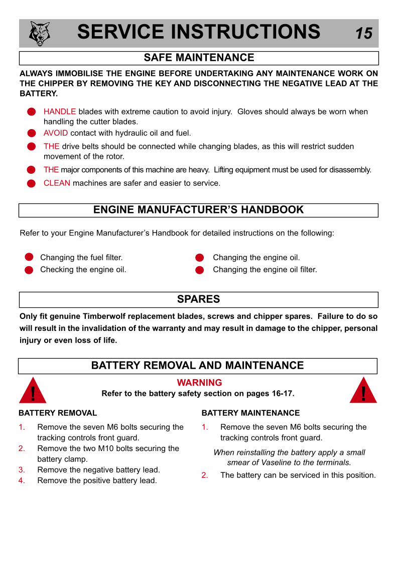
ALWAYS IMMOBILISE THE ENGINE BEFORE UNDERTAKING ANY MAINTENANCE WORK ON
THE CHIPPER BY REMOVING THE KEY AND DISCONNECTING THE NEGATIVE LEAD AT THE
BATTERY.
HANDLE blades with extreme caution to avoid injury. Gloves should always be worn when
handling the cutter blades.
AVOID contact with hydraulic oil and fuel.
THE drive belts should be connected while changing blades, as this will restrict sudden
movement of the rotor.
THE major components of this machine are heavy. Lifting equipment must be used for disassembly.
CLEAN machines are safer and easier to service.
SAFE MAINTENANCE
Only fit genuine Timberwolf replacement blades, screws and chipper spares. Failure to do so
will result in the invalidation of the warranty and may result in damage to the chipper, personal
injury or even loss of life.
SPARES
BATTERY REMOVAL AND MAINTENANCE
WARNINGRefer to the battery safety section on pages 16-17. !!
BATTERY REMOVAL
1. Remove the seven M6 bolts securing the
tracking controls front guard.
2. Remove the two M10 bolts securing the
battery clamp.
3. Remove the negative battery lead.
4. Remove the positive battery lead.
BATTERY MAINTENANCE
1. Remove the seven M6 bolts securing the
tracking controls front guard.
2. The battery can be serviced in this position.
When reinstalling the battery apply a smallsmear of Vaseline to the terminals.
Refer to your Engine Manufacturer’s Handbook for detailed instructions on the following:
Changing the fuel filter.
Checking the engine oil.
Changing the engine oil.
Changing the engine oil filter.
ENGINE MANUFACTURER’S HANDBOOK

SERVICE INSTRUCTIONS 16
SAFE LIFTING & SECURING DOWN OF THE CHIPPER
The lifting eye is designed to lift the machine’s weight only. Do not use
hoist hook directly on the lifting eye, use a correctly rated safety shackle.
Inspect the lifting eye prior to each use - DO NOT USE LIFTING EYE IF
DAMAGED.
The Timberwolf TW 150VTR has 2 identical tie down points incorporated into their chassis frames for
the purpose of securing them to trailers or flat bed carriers. These points are located at the front and
back of the machine on the longitudinal chassis ‘track adaptor’ frame, and are in the form of a 16mm
solid rod. It is essential that at a minimum, the load rating of the straps used are 5000kg, and the
straps themselves are at least 50mm wide.
GREASING ROTOR BEARINGS
Both front and rear bearings are sealed and do not need greasing.
Tie down points located at front and back of chipper
The method of securing the chipper can vary depending on the type of carrier, and the
positions of the tie-down points available on the carrier. Securing aTimberwolf chipper for
transport should only be done by qualified personnel.

SERVICE INSTRUCTIONS 17
WARNING NOTES AND SAFETY REGULATIONS FOR FILLED LEAD-ACID BATTERIES
For safety reasons, wear eye protection when handling a battery.
Keep children away from acid and batteries.
Fires, sparks, naked flames and smoking are prohibited.-Avoid causing sparks when dealing with cables and electrical equipment, and beware of electrostatic discharges.-Avoid short circuits, otherwise:
Explosion hazard:-A highly explosive oxyhydrogen gas mixture is produced when batteries are charged.
Corrosive hazard:-Battery acid is highly corrosive, therefore:-Wear protective gloves and eye protection.-Do not tilt the battery, acid may escapefrom the vent openings.
First aid:-Rinse off acid splashed in the eyes immediatelyfor several minutes with clear water! Then consult a doctor immediately.
-Neutralise acid splashes on the skin or clothes immediately with acid neutraliser (soda) or soapsuds, and rinse with plenty of water.
-If acid is swallowed, consult a doctor immediately.
Warning notes: The battery case can become brittle, toavoid this:
-Do not store batteries in direct sunlight.-Discharged batteries may freeze up, therefore store in an area free from frost.
Disposal:-Dispose of old batteries at an authorised collection point.
-The notes listed under item 1 are to be followedfor transport.
-Never dispose of old batteries in household waste.
BATTERY SAFETY INFORMATION
Product name: Copper Ease.
Copper Ease contains no hazardous ingredients at or above regulatory disclosure limits, however,
safety precautions should be taken when handling (use of oil-resistant gloves and saftey glasses are
recommended - respiratory protection is not required). Avoid direct contact with the substance and
store in a cool, well ventilated area avoiding sources of ignition, strong oxidising agents and strong
acids. Dispose of as normal industial waste (be aware of the possible existance of regional or national
regulations regarding disposal), do not discharge into drains or rivers.
In case of fire: in combustion the product emits toxic fumes, extinguish with alcohol or polymer foam,
carbon dioxide or dry chemical powder. Wear self-contained breathing apparatus and protective clothing
to prevent contact with skin and eyes.
FIRST AID
Skin contact: there may be mild irritation at the site of contact, wash immediately with plenty of soap
and water.
Eye contact: there may be irritation and redness, bathe the eye with running water for 15 minutes.
Ingestion: there may be irritation of the throat, do not induce vomiting, wash out mouth with water.
A safety data sheet for this product can be obtained by writing to the manufacturer at the
following address: Comma Oil and Chemicals Ltd., Deering Way, Gravesend, Kent DA12 2QX.
Tel: 01474 564311, Fax: 01474 333000.
COPPER EASE SAFETY INFORMATION

SERVICE INSTRUCTIONS 18
1. Storage and transport- Batteries are filled with acid.- Always store and transport batteries upright
and prevent from tilting so that no acid can escape.
- Store in a cool and dry place.- Do not remove the protective cap from the
positive terminal.- Run a FIFO (first in-first out)warehouse
management system.
2. Initial operation- The batteries are filled with acid at a density of
1.28g/ml during the manufacturing process andare ready for use.
- Recharge in case of insufficient starting power (cf. section 4).
3. Installation in the vehicle and removal fromthe vehicle
- Switch off the engine and all electrical equipment.
- When removing, disconnect the negative terminal first.
- Avoid short circuits caused by tools, for example.- Remove any foreign body from the battery tray,
and clamp battery tightly after installation.- Clean the terminals and clamps, and lubricate
slightly with battery grease.- When installing, first connect the positive
terminal, and check the terminal clamps for tight fit.
- After having fitted the battery in the vehicle, remove the protective cap from the positive terminal, and place it on the terminal of the replaced battery in order to prevent short circuits and possible sparks.
- Use parts from the replaced battery, such as the terminal covers, elbows, vent pipe connection and terminal holders (where applicable); use available or supplied filler caps.
- Leave at least one vent open, otherwise there is a danger of explosion. This also applies when old batteries are returned.
4. Charging- Remove the battery from the vehicle;
disconnect the lead of the negative terminal first.- Ensure good ventilation.- Use suitable direct current chargers only.- Connect the positive terminal of the battery to
the positive output of the charger. Connect thenegative terminal accordingly.
- Switch on the charger only after the battery hasbeenconnected, and switch off the charger firstafter charging has been completed.
- Charging current-recommendation: 1/10 ampere of the battery capacity Ah.
- Use a charger with a constant charging voltageof 14.4V for re-charging.
- If the acid temperature rises above 55o Celsuis,stop charging.
- The battery is fully charged when the charging voltage has stopped rising for two hours.
5. Maintenance- Keep the battery clean and dry.- Use a moist anti-static cloth only to wipe the
battery, otherwise there is a danger of explosion.
- Do not open the battery.- Recharge in case of insufficient starting power
(cf. section 4).
6. Jump Starting- Use the standardised jumper cable in
compliance with DIN 72553 only, and follow theoperating instructions.
- Use batteries of the same nominal voltage only.- Switch off the engines of both vehicles.- First connect the two positive terminals (1) and
(2), then connect the negative terminal of the charged battery (3) to a metal part (4) of the vehicle requiring assistance away from the battery.
- Start the engine of the vehicle providing assistance, then start the engine of the vehicle requiring assistance for a maximum of 15 seconds.
- Disconnect the cables in reverse sequence (4-3-2-1).
7. Taking the battery out of service- Charge the battery; store in a cool place or in
the vehicle with the negative terminal disconnected.
- Check the battery state of charge at regular intervals, and correct by recharging when necessary (cf. section 4).
(1)(2)
(3) (4)
12V 12V
BATTERY SAFETY INFORMATION...cont.

SERVICE INSTRUCTIONS 19
WARNINGUse plastic gloves to keep oil off skin and dispose of the used oil and filter
in an ecologically sound way. The oil and filter should be changed once a
year or at any time it becomes contaminated. Before starting check that the
chipper is standing level and brush away loose chips.
CHANGE HYDRAULIC OIL AND FILTER
! !
2
1
4
1. Remove the black screw cap from the top of
the filter housing.
2. Partially remove filter element from inner cup.
Leave filter to drain for 15 minutes.
3. Remove filter element from cup when clear of
hydraulic oil.
4. Remove drain plug and drain oil into a suitable
container.
5. Replace drain plug.
6. Refill with VG 32 hydraulic oil until the level is
between the min and max marks (about 15
litres).NOTE: This is a non-adjustable air breather filter.
CHECK FITTINGS
All the hydraulic hoses should be regularly inspected for chafing and leaks. The hydraulic system is
pressurized to over 150 Bar (2175 PSI) and thus the equipment containing it must be kept in good condition.
Identify the hoses that run to the top motor. These have the highest chance of damage as they are
constantly moving. If any hydraulic components are changed new seals should be installed during
reassembly. Fittings should then be retightened.
The Timberwolf TW 150VTR is subject to large vibrations during the normal course of operation.
Consequently there is always a possibility that nuts and bolts will work themselves loose. It is
important that periodic checks are made to ensure the security of all fasteners. Fasteners should be
tightened using a torque wrench to the required torque (see below). Uncalibrated torque wrenchescan be inaccurate by as much as 25%. It is therefore essential that a calibrated torque wrenchis used to achieve the tightening torques listed below.
CHECK HOSES
Size Pitch Head Torque Ibft Torque Nm
Blade Bolts M10 Standard T50 Torx 45 61
Hyd Motor Retaining Bolts M10 Standard 17mm Hex 34 46
Funnel Retaining Nuts M12 Standard 17mm Hex 38 51
General M8 Standard 13 mm Hex 17 23
General M10 Standard 17 mm Hex 34 46
General M12 Standard 19 mm Hex 60 80Drain Bung in Fuel Tank 3/8” BSP - 22 mm Hex 25 33.8
7. Refit the filter cup, install a new filter element and refit the black screw cap to the filter housing,
ensuring o-ring remains in place.

SERVICE INSTRUCTIONS 20
1. Turn the chipper off and remove the ignition keys.
2. Remove battery leads.
3. Remove bolt and washer retaining roller box guard and lift guard.
4. Remove the two springs on the roller box slide.
5. NOTE: Rollerbox slide weighs in excess of 20kg. Lift the roller box slide and wedge a suitably sized piece of wood to hold in place.
6. Remove blade access cover.
7. Remove discharge tube. Turn the rotor by handby grasping fan section on rear of rotor disc untilblade is visible through aperture.
8. Use a small screwdriver to remove sap and debris from Torx socket in screw - be particularly careful to ensure every last piecehas been removed.
9. Undo blade screws using Torx socket driveprovided. Rotor will turn until Torx socket has located on machine.
10. Before fitting replacement blades carefullyclean blade recess in rotor so that no debrisis trapped between blade and rotor.
11. When fitting blades replace any damaged screws with new and coat each screw with copperslip over the whole of the thread.
12. Retighten each screw to 60Nm (45lbs ft).
NOTE: This torque setting is vitally important to ensure your bolts come out at a later date,Timberwolf recommend you purchase a torque wrench for this and other jobs on the chipper.
13. Grease all surfaces of the roller box slidingmechanism (see diagram on page 21).
14. Replace blade access cover.
15. NOTE: Rollerbox slide weighs in excess of 20kg.Remove wedge, lower roller box slide and replace springs.
16. Close roller box guard making sure that it is located over the retaining bracket, and ensure bolt and washer (as note 3) are tightened.
17. Refit battery leads.
WARNINGWear riggers gloves for the blade changing operation.
CHANGE BLADES
!!
4
5
6
8
9
10
3
7
WARNINGAlways sharpen blades on a regular basis. Failure to do so willcause the machine to under perform and will overload engine andbearings causing machine breakdown. Blades must not besharpened beyond the wear mark (see diagram). Failure to complywith this could result in machine damage, injury or loss of life.
!!WEARMARK

SERVICE INSTRUCTIONS 21TENSION BELTS
2
3
NOTE: This should be done regularly. In dirty and dustyconditions or during periods of hard work it should be weekly.If the bearings and splines are allowed to run dry prematurewear will occur resulting in a breakdown and the need forreplacement parts. This failure is not warranty. Early signs ofinsufficient grease includes squeaking or knocking rollers.
1. Remove bolt and washer retaining roller box guard and lift guard (see diagram on page 19).
2. Locate two grease nipples; one in the centre of each roller shaft.
3. Use a pump action grease gun to apply a generous amount of grease to each roller drive. DO NOT USE GRAPHITE BASED GREASE. After applying grease, to penetrate all the bearing surfaces thoroughly, start the machine and operate the rollers for 20 seconds. Switch off the machine. Repeat this greasing/running procedure a further 3 times.
4. Close roller box guard making sure that it is located over the retaining bracket, and ensure bolt and washer are tightened.
2
1. Loosen the three outermost M8 nuts and bolts.
2. Pivot pump assembly up or down to achieve the correct belt
tension. For instructions on checking belt tension & correct
belt tension values, please refer to the Timberwolf V-Belt
Tensioning Data Table (pg. 58).
3. Hold assembly at this position while tightening the three M8
nuts and bolts.
1
1. Remove side panel.
2. Loosen bolt in centre of tensioner pulley with a 19 mm spanner
so that pulley is able to slide with minimal wobble.
3. Turn nut in end of tensioner pulley slider until correct belt
tension is achieved. For instructions on checking belt tension
& correct belt tension values, please refer to the Timberwolf
V-Belt Tensioning Data Table (pg. 58).
5. Re-tighten bolt in centre of tensioner pulley.
6. Run machine and test, recheck belt tension.
7. NOTE: Slack drive belts will cause poor performance and excess
belt and pulley wear.
TENSION HYDRAULIC PUMP BELT
NOTE: There will normally be a rapid drop in tension during run-in period for new belts. When newbelts are fitted, check the tension every 2 - 3 hours and adjust until the tension remains constant.
Belt failures due to lack of correct tensioning will not be covered under your Timberwolf warranty.TENSION DRIVE BELTS
GREASE THE ROLLER SPLINE AND BEARINGS
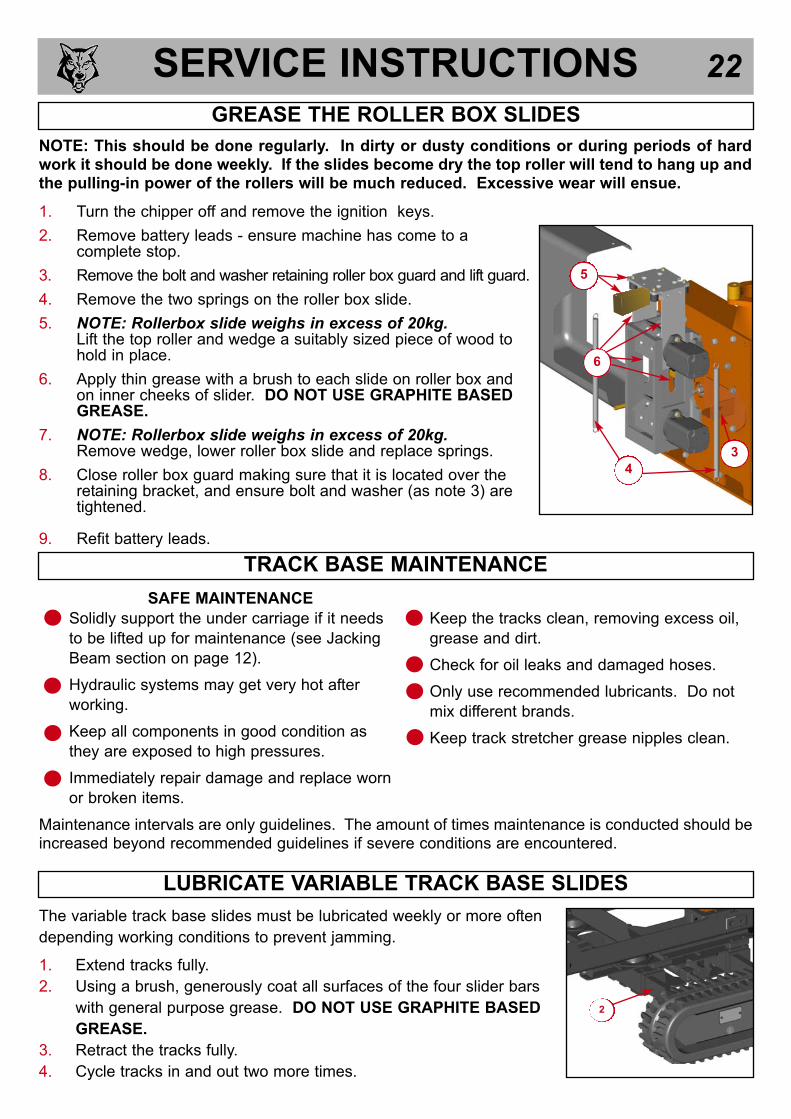
SERVICE INSTRUCTIONS 22GREASE THE ROLLER BOX SLIDES
NOTE: This should be done regularly. In dirty or dusty conditions or during periods of hardwork it should be done weekly. If the slides become dry the top roller will tend to hang up andthe pulling-in power of the rollers will be much reduced. Excessive wear will ensue.
1. Turn the chipper off and remove the ignition keys.
2. Remove battery leads - ensure machine has come to a complete stop.
3. Remove the bolt and washer retaining roller box guard and lift guard.
4. Remove the two springs on the roller box slide.
5. NOTE: Rollerbox slide weighs in excess of 20kg.Lift the top roller and wedge a suitably sized piece of wood to hold in place.
6. Apply thin grease with a brush to each slide on roller box and on inner cheeks of slider. DO NOT USE GRAPHITE BASED GREASE.
7. NOTE: Rollerbox slide weighs in excess of 20kg.Remove wedge, lower roller box slide and replace springs.
8. Close roller box guard making sure that it is located over the retaining bracket, and ensure bolt and washer (as note 3) are tightened.
9. Refit battery leads.
6
3
5
4
SAFE MAINTENANCE
Solidly support the under carriage if it needs
to be lifted up for maintenance (see Jacking
Beam section on page 12).
Hydraulic systems may get very hot after
working.
Keep all components in good condition as
they are exposed to high pressures.
Immediately repair damage and replace worn
or broken items.
Keep the tracks clean, removing excess oil,
grease and dirt.
Check for oil leaks and damaged hoses.
Only use recommended lubricants. Do not
mix different brands.
Keep track stretcher grease nipples clean.
TRACK BASE MAINTENANCE
Maintenance intervals are only guidelines. The amount of times maintenance is conducted should beincreased beyond recommended guidelines if severe conditions are encountered.
The variable track base slides must be lubricated weekly or more often
depending working conditions to prevent jamming.
1. Extend tracks fully.
2. Using a brush, generously coat all surfaces of the four slider bars
with general purpose grease. DO NOT USE GRAPHITE BASED
GREASE.
3. Retract the tracks fully.
4. Cycle tracks in and out two more times.
LUBRICATE VARIABLE TRACK BASE SLIDES
2

SERVICE INSTRUCTIONS 23
To drain the oil, track the machine until a plug is at 6 o’clock as shown.
Unscrew both plugs and allow oil to discharge into a suitable container.
Dispose of waste oil in a safe and approved way.
DRAINING THE OIL IN THE TRACK DRIVE UNIT
REDUCTION UNIT OIL TYPES
We recommend, for track drive gearboxes, using gear oils with E>P. additives and viscosity to SAE
80W/90 or ISO VG 150. Continuous duty temperature must not exceed 90oC.
The structure of the rubber track is shown in this diagram.The steel cables (1) and metal core (2) are embedded in therubber.
There are many ways in which rubber tracks may bedamaged. Some of these are terminal for the tracks, othersare only cosmetic.
CHECKING THE RUBBER TRACKS
BREAKAGES OF STEEL CABLES AND METAL CORES.
Excess track tension can cause steel cables to break. Excess tension may be caused by;
Stones or foreign matter accumulating between the track and the undercarriage frame.
The track slipping off its guide system.
Extreme friction such as rapid changes in direction.
Improper contact between track and sprocket.
Operation on sandy terrain.
FATIGUE CRACKS AND ABRASION.
Cracks at the base of tile carved profiles are caused by rubber fatigue due to bending.
Cracks and bends on the edge of the rubber are caused by manoeuvring the track on concrete edgesand curbs.
Cracks and abrasions in the rubber on the guide roller paths are caused by compression fatigue ofthe rubber due to the weight of the wheel combined with operation on sandy terrain or repeatedsudden changes in direction.
Abrasion of the carved profile may be caused, in particular, by rotation on concrete or gravel surfacesor hard surfaces.
Cracks on the outside surface of the track are often due to contact with gravel, sharp stones and sharpmaterials such as sheet metal, nails and glass.
Cracks on the inside surface of the circumference and on the edge of the rubber are caused bycontact between track and the undercarriage structure or with sharp concrete edges.
These methods of damage are progressive. The track can continue to be used until wear exposesthe metal cores. If this exposure extends for more than half of the circumference of the track then itis time to replace the track, even though it can still be used.
SPROCKET HOLE
CARVED
PROFILE
1
2
REPLACE OIL IN THE TRACK DRIVE UNIT
To fill with oil, track the machine until the gearbox casing is level with a
plug positioned at 12 o’clock as shown. Unscrew the two plugs and fill
from the upper hole until oil reaches the level of the lower hole.
NOTE - Ensure the correct grade of oil is used: Gear Oil EP80W-90 GL5
OIL FILL
MAXIMUM LEVEL
DRAIN PORT
VENTING

SERVICE INSTRUCTIONS 24CHECKING TRACK TENSION
1. Stop your machine on a flat
and solid surface.
2. Lift it in safe conditions and
put stable supports under
the undercarriage frame to
properly support it.
3. Measure distance A at the
central roller of the undercarriage from the bottom of the roller to the rigid inside surface of the
rubber track. Track tension is normal if dimension A is between 70 and 75 mm.
4. Adjust tension as described in the following paragraph if track tension does not comply with
these dimensions (loose or too tight).
A
TRACK LOOSENING/TIGHTENING PROCEDURES
Track tension is maintained by grease in the adjuster unit. Adding more grease will increase tracktension, removing grease will decrease it.
The grease contained in the hydraulic track tensioner ram is pressurized. Never release grease nipple(No. 1, Fig. 1) for more than necessary to slowly release grease to a maximum of five turns. If thevalve is loosened too much you risk expelling grease under pressure and possible injury to themachine operator. Remove gravel or mud when they are jammed between the sprocket and the tracklink before loosening the track.
1. Locate access hole in side frame (fig. 1) to access the adjustment system.
2. To loosen the track turn the grease nipple counter-clockwise slowly, the grease should begin tobe expelled after approximately two turns.
3. If grease does not start to drain out then slowly rotate the track forward and reverse to free adjuster mechanism - grease may then be expelled under pressure as track tension is relieved.
WARNINGIt is not normal for the track to remain too tight after turning the grease nipple
counter-clockwise or for it to remain loose after introducing grease into the
grease nipple. Never try to remove the tracks or disassemble the track-
stretching cylinder since pressure of the grease inside the track is dangerous.
! !
1
4. When you have obtained correct track tension then turn valve clockwise and tighten it. Clean all traces of extruded grease.
5. To stretch the track connect a grease gun to grease nipple and add grease until track tension falls within specified values.
Fig. 1
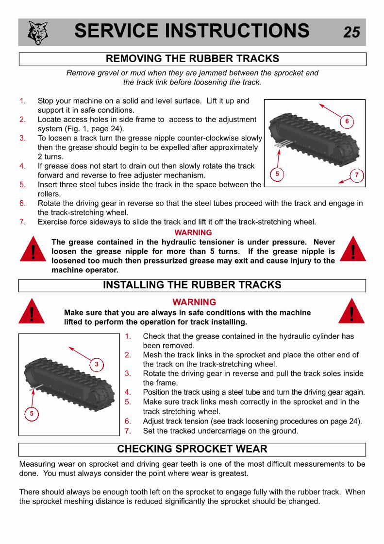
SERVICE INSTRUCTIONS 25
1. Check that the grease contained in the hydraulic cylinder has
been removed.
2. Mesh the track links in the sprocket and place the other end of
the track on the track-stretching wheel.
3. Rotate the driving gear in reverse and pull the track soles inside
the frame.
4. Position the track using a steel tube and turn the driving gear again.
5. Make sure track links mesh correctly in the sprocket and in the
track stretching wheel.
6. Adjust track tension (see track loosening procedures on page 24).
7. Set the tracked undercarriage on the ground.
! !WARNING
Make sure that you are always in safe conditions with the machine
lifted to perform the operation for track installing.
INSTALLING THE RUBBER TRACKS
Measuring wear on sprocket and driving gear teeth is one of the most difficult measurements to be
done. You must always consider the point where wear is greatest.
There should always be enough tooth left on the sprocket to engage fully with the rubber track. When
the sprocket meshing distance is reduced significantly the sprocket should be changed.
CHECKING SPROCKET WEAR
3
5
Remove gravel or mud when they are jammed between the sprocket and the track link before loosening the track.
1. Stop your machine on a solid and level surface. Lift it up and
support it in safe conditions.
2. Locate access holes in side frame to access to the adjustment
system (Fig. 1, page 24).
3. To loosen a track turn the grease nipple counter-clockwise slowly
then the grease should begin to be expelled after approximately
2 turns.
4. If grease does not start to drain out then slowly rotate the track
forward and reverse to free adjuster mechanism.
5. Insert three steel tubes inside the track in the space between the
rollers.
6. Rotate the driving gear in reverse so that the steel tubes proceed with the track and engage in
the track-stretching wheel.
7. Exercise force sideways to slide the track and lift it off the track-stretching wheel.
REMOVING THE RUBBER TRACKS
WARNING
The grease contained in the hydraulic tensioner is under pressure. Never
loosen the grease nipple for more than 5 turns. If the grease nipple is
loosened too much then pressurized grease may exit and cause injury to the
machine operator.
! !
5
6
7

WARRANTY STATEMENT 26
WARRANTY PERIOD
The warranty period for the woodchipper commences on the date of sale to the first end user and continues for
a period of 12 months. This guarantee is to the first end user only and is not transferable except when an
authorised Timberwolf Dealer has a woodchipper registered with Environmental Manufacturing LLP as a hire
chipper or long term demonstrator – in these situations they are duly authorised to transfer any remaining
warranty period to their first end user. Any warranty offered by the Timberwolf Dealer beyond the original 12
month period will be wholly covered by said Dealer.
LIABILITY
Our obligation under this warranty is limited to repair at Environmental Manufacturing LLP premises or at our
option an Environmental Manufacturing LLP approved Timberwolf dealer. No liability will be accepted for
special, indirect, incidental, or consequential loss or damages of any kind.
WARRANTY STATEMENT
Environmental Manufacturing LLP warrants to the first end user that;
-Your woodchipper shall be designed, built and equipped, at the point of sale, to meet all current applicable
regulations.
-Your chipper shall be free from manufacturing defects both in materials and workmanship in normal service for
the period mentioned above.
Warranty will not apply to a failure where normal use has exhausted the life of a component.
Engine units are covered independently by their respective manufacturer warranties.
OWNERS WARRANTY RESPONSIBILITIES
As the owner of an Environmental Manufacturing LLP woodchipper you are responsible for the following;
-Operation of the woodchipper in accordance with the Environmental Manufacturing LLP instruction manual.
-Performance of the required maintenance listed in your Environmental Manufacturing LLP instruction manual.
-In the event of a failure the Environmental Manufacturing LLP authorised Timberwolf dealer is to be notified
within 10 days of failure and the equipment is to be made available for unmolested inspection by the dealer
technician.
WARRANTY RESTRICTIONS
The Environmental Manufacturing LLP warranty is restricted to the first end user only and is not transferable
except when an authorised Timberwolf Dealer has a woodchipper registered with Environmental Manufacturing
LLP as a hire chipper or long term demonstrator – in these situations they are duly authorised to transfer any
remaining warranty period to their first end user.
The Environmental Manufacturing LLP warranty may be invalidated if any of the following apply;
-The failed parts or assembly is interfered with in any way.
-Normal maintenance has not been performed.
-Incorrect reassembly of components.
-The machine has undergone modifications not approved in writing by Environmental Manufacturing LLP.
-In the case of tractor driven equipment, use has been on an unapproved tractor.
-Conditions of use can be deemed abnormal.
-The machine has been used to perform tasks contrary to those stated in the Environmental Manufacturing LLP
instruction manual.
WARRANTY SERVICE
To obtain warranty service please contact your nearest Environmental Manufacturing LLP approved Timberwolf
dealer. To obtain details of the nearest facility please contact Environmental Manufacturing LLP at the address
on the front of this manual.
These warranty terms are in addition to and not in substitution for and do not affect any right and remedies which
an owner might have under statute or at common law against the seller of the goods under the contract by which
the owner acquired the goods.
ENVIRONMENTAL MANUFACTURING LLP 12 MONTH CHIPPER WARRANTY

CERTIFICATE OF CONFORMITY27

IDENTIFICATION PLATE 28
E X A MP L E

DECALS 29
WARNING
DO NOT RIDE ON
THIS MACHINE AT
ANY TIME
TR
AC
K
CH
IP
PUSH PULL TO STOPORJACKING
POINT
SEE MANUAL FOR
INSTRUCTIONS
3059
Low Funnel Only
High Funnel Only
Low Funnel Only
PUSH TO STOP
1200KGMAX
TW 150VTR SELECT
CHIP MODEWHEN ADJUSTING
TRACK WIDTH
119 dB
LWA
Last Updated 1st Dec 2010
616 617 670 671 1136 x 2
!HOT
EXHAUST
HIGH
VELOCITY
DISCHARGE
KEEP CLEAR!
TIMBERWOLF
OPERATING INSTRUCTIONS
READ THE INSTRUCTION MANUAL.
THE INSTRUCTION MANUAL WITH THIS MACHINE
CONTAINS IMPORTANT OPERATING, MAINTENANCE AND
HEALTH AND SAFETY INFORMATION.
FAILURE TO FOLLOW THE INFORMATION CONTAINED IN
THE INSTRUCTION MANUAL MAY LEAD TO DEATH OR
SERIOUS INJURY.
GREASE ROLLER
SPINDLE AND
SLIDES
! SAFETY NOTE !LIFTING EYE IS DESIGNED TO LIFT THE
MACHINE’S WEIGHT ONLY.
DO NOT USE HOIST HOOK DIRECTLY ON LIFTING EYE.
USE CORRECTLY RATED SAFETY SHACKLE
ONLY THROUGH LIFTING EYE.
LIFTING EYE TO BE INSPECTED EVERY 6 MONTHS
OR BEFORE EACH USE.
ALWAYS VISUALLY INSPECT LIFTING EYE PRIOR TO
EACH USE. DO NOT USE LIFTING EYE IF DAMAGED.
!! ATTENTION !!CLEAN UNDER BLADES BEFORE
REFITTING OR TURNING
FAILURE TO DO SO MAY RESULT IN
BLADE(S) COMING LOOSE AND DAMAGE
BEING CAUSED TO THE ROTOR HOUSING
PU
SH TO STOP
PU
LLTO RES
ET
92 dB
!! ATTENTION !!NEW DRIVE BELTS NEED
RE-TENSIONING
WHEN NEW BELTS ARE FITTED CHECK
TENSION EVERY 2-3 HOURS & ADJUST
UNTIL TENSION REMAINS CONSTANT.
!
!
!!
!
!
DANGER
DANGER
DANGER DANGER DANGER
DANGER
SEE NEXT PAGE FOR D
ETAIL
1363 1399 1661 1662
1745 1746 1747 2800 2801 2802 X 2 2854
2949 2950 2998 3004 3015 3022
3059 x 2 3054 4099 X 2 4114
X 2 onlow funnel
4276 X 2 4284 17450 18393 18438
PUSH TO STOP
DO NOT PULL HERE
OUT
Variable
tracks
only
IN
!! ATTENTION !!WHEN RE-FITTING THS GUARD ENSURE THAT STEEL RETAININGBRACKET IS ON THE INSIDEDAMAGED GUARDS DUE TO INCORRECT
ASSEMBLY WILL NOT BE COVERED BY
YOUR TIMBERWOLF WARRANTY
LAeq
19517 19518
WARNINGDO NOT ENGAGE STARTER MOTOR
FOR MORE THAN
20 SECONDSALLOW ONE MINUTE BEFORE ATTEMPTING TO START
INVESTIGATE REASONS FOR FAILURE TO START
EXCESSIVE CRANKING WILL RESULT IN STARTER MOTOR FAILURE. THIS WILL NOT BE COVERED UNDER WARRANTY.
WARNING
WHEN THE EMERGENCY STOP BUTTON
IS PRESSED IT MUST BE PULLED OUT
AGAIN AND THE IGNITION SWITCH
TURNED OFF TO RESET THE MACHINE
BEFORE ATTEMPTING TO RESTART.
SEE THE 20 SECOND DECAL SITUATED NEAR THE IGNITION SWITCH

DECALS 30
!!
!!!!!
!
DA
NG
ER
DA
NG
ER
DA
NG
ER
DA
NG
ER
DA
NG
ER
DA
NG
ER
DA
NG
ER
DA
NG
ER
DO
NO
T O
PE
RA
TE
WIT
HO
UT
TH
IS
CO
VE
R I
N P
LA
CE
DO
NO
T O
PE
RA
TE
WIT
HO
UT
TH
IS
CO
VE
R I
N P
LA
CE
DO
NO
T O
PE
RA
TE
WIT
HO
UT
TH
IS
CO
VE
R I
N P
LA
CE
DO
NO
T O
PE
RA
TE
WIT
HO
UT
TH
IS
CO
VE
R I
N P
LA
CE
FU
EL H
ER
E
RIS
K O
F F
IRE
CA
UT
ION
RO
TA
TIN
G
BL
AD
ES
CA
UT
ION
CA
UT
ION
WH
EN
TR
AN
SP
OR
TIN
GD
ISC
HA
RG
E C
LA
MP
S M
AY
WO
RK
LO
OS
E.
C
HE
CK
FR
EQ
UE
NT
LY
AV
OID
STA
ND
ING
DIR
EC
TLY
IN
FR
ON
T O
F F
EE
D F
UN
NE
L T
OR
ED
UC
E E
XP
OS
UR
E T
O N
OIS
E,
DU
ST A
ND
RIS
K F
RO
M E
JE
CTE
DPA
RTIC
LE
S
DO
NO
T U
SE
TH
IS M
AC
HIN
E
WIT
HO
UT T
HE
DIS
CH
AR
GE
UN
IT
FIT
TE
D F
AIL
UR
E T
O C
OM
PLY
MA
Y R
ES
ULT IN
SE
RIO
US
INJU
RY
OR
DA
MA
GE
STO
P E
NG
INE
AN
D R
EM
OV
E
KE
Y B
EFO
RE
RE
MO
VIN
G
DIS
CH
AR
GE
UN
IT. R
OTA
TIN
G
BLA
DE
S IN
SID
E.
DO
NO
T P
UT
RO
AD
SW
EE
PIN
GS
IN
MA
CH
INE
AS
GR
IT W
ILL D
AM
AG
EB
LA
DE
S
AL
LO
W E
NG
INE
TO
CO
OL
FO
R1 M
INU
TE
BE
FO
RE
RE
FU
EL
ING
.U
SE
UN
LE
AD
ED
PE
TR
OL
AU
TO
FE
ED
SY
STE
M F
ITTE
D.
RO
LLE
RS
MA
Y T
UR
N W
ITH
OU
TW
AR
NIN
G!
WH
EN
EN
GIN
E IS
SW
ITC
HE
D O
FTH
E R
OLLE
RS
WIL
L T
UR
ND
UR
ING
TH
E R
UN
DO
WN
PE
RIO
D
671 - these individual decals are supplied as a set, they may not all apply to your machine.

ELECTRICAL DETAILS 31
Date Last Modified: 11th Nov 05
High funnel
versions only
Low funnel
versions only

CIRCUIT DIAGRAM 32
DO
CU
ME
NT
No.
ISS
UE
CIR
CU
IT D
IAG
RA
M F
OR
: 15
0 (W
ITH
H-B
OX
) H
IGH
AN
D L
OW
FU
NN
EL
VE
RS
ION
S1
150-
CD
CO
MP
ON
EN
T L
IST
(LO
W F
UN
NE
L -
TR
AC
KE
D):
MA
IN L
OO
M: 1
7277
/2, L
OW
FU
NN
EL
LOO
M: 3
019/
1, S
AF
ET
Y S
WIT
CH
LO
OM
: 401
7/1
CO
NF
IGU
RA
TIO
N T
.B.A
.
FD ECBA
SP
LIT
TO
FU
NN
EL
LO
OM
TAC
HO
SIG
/ A
LT
FU
NN
EL
SA
FE
TY
SW
ITC
H
PA
RT
No
. 401
7
PA
RT
No
. 301
9 (L
OW
FU
NN
EL
)
SP
LIT
TO
FU
NN
EL
SA
FE
TY
SW
ITC
H
SP
LIT
TO
FU
NN
EL
SA
FE
TY
SW
ITC
H
FUS
E 1
IGP
FUS
E 2
AU
X
AU
X P
OW
ER
CO
NN
B
21
BLG G
BL/
W
1-A
C3m
m
411m
m12
.5m
m
1mm
40 151m
m
1.5m
m16
1mm
2mm
155
BLU
ES
P#4
.5m
m8
1mm
40
3mm
48182m
m
1mm
20401m
m
391m
m
401m
m
80.
5
50E
1mm
40401m
m
1mm
1mm
33 281m
m
GR
EEN
SP
#2
BLA
CK
SP
#1
LA
TC
H R
EL
AY
FW
D S
OL
8530
87a 8687
BL/
G
B
SO
LE
NO
IDF
WD
RE
VE
RS
ES
OL
EN
OID
23
12
31
BR
B/B
R
WB
R
LE
D
HE
AT
ER
SO
N L
ED
BB
R/R
NO
-ST
RE
SS
B
SA
FETY
SW
N.O
./N.C
.
BL/
R
REV
STO
P
N.C
./N.C
.
FWD
B
B
LAC
K
BL
B
LUE
BR
B
RO
WN
R
R
ED
G
G
RE
EN
Y
Y
ELL
OW
P
P
UR
PLE
W
W
HIT
E
B/G
B
LAC
K W
ITH
GR
EE
N T
RA
CE
R
BL/
R
BLU
E W
ITH
RE
D T
RA
CE
R
BL/
G
BLU
E W
ITH
GR
EE
N T
RA
CE
R
KE
Y T
O W
IRIN
G 1
50T
R
O
OR
AN
GE
B/R
B
LAC
K W
ITH
RE
D T
RA
CE
R
BL/
W
BLU
E W
ITH
WH
ITE
TR
AC
ER
P/W
P
UR
PLE
WIT
H W
HIT
E T
RA
CE
R
B/B
R
BLA
CK
WIT
H B
RO
WN
TR
AC
ER
BL/
B B
LUE
WIT
H B
LAC
K T
RA
CE
R
W/R
WH
ITE
WIT
H R
ED
TR
AC
ER
Y/B
YE
LLO
W W
ITH
BLU
ET
RA
CE
R
O/W
OR
AN
GE
WIT
H W
HIT
E T
RA
CE
R
O/Y
OR
AN
GE
WIT
H Y
ELL
OW
TR
AC
ER
AL
TE
RN
AT
OR
RO
TOR
O/P
ST
AR
TE
R
BA
TT
ER
Y
ST
AR
TE
RS
OL
TE
RM
GL
OW
PL
UG
SEN
G G
ND
PO
INT
BA
TT
25m
m
BA
TT
25m
m RR
BL
R
BL/
B
AC
C
OFF
RU
N
STA
RT
HO
UR
FU
EL
E
NG
INE
GR
OU
ND
PO
INT
R
PU
MP
ME
TE
R
B
BL
B
FU
EL
S
OL
EN
OID
PU
LL
HO
LD
21 P/W
P
KE
Y S
WIT
CH
EM
ER
GE
NC
Y
SW
ITC
H
CD
B
GR
OU
ND
SE
CU
RIT
Y
EN
GIN
E
B
pt
WA
TE
R T
EM
PS
WIT
CH
OIL
PR
ES
S
SW
ITC
H
Y/B
L
Y/R
B BL
BR
/B
BR
/R
BR
/R
BR
OW
N W
ITH
RE
D T
RA
CE
R
Y/R
Y
ELL
OW
WIT
H R
ED
TR
AC
ER
Y/R
Y/B
L
B/R
BR O
R/W
BR
BR
G
R
P/W O
WBL
OBL/
G
B/G
BL/
G
P/W
P/W
WBL
B/G
BL
P/W P/W
B/G
351m
m
N.O
./N.C
.
N.O
./N.C
.
AB
MA
IN T
ER
M
ST
AR
TE
RM
OT
OR
OV
ER
RID
E
SP 1
SP 1
SP 1
SP 1
SP 1
SP 1
SP 1
SP 1
SP 1
SP 4
SP 4
SP 4
SP 4
SP 4SP 2 SP 2
SP 2
SP 5
AB
CD
CD
AB
OB
L/R
N.O
./N.C
.
1314
2122
N.O
.
1314
AB
C
PO
SIT
IVE
BA
TT
ER
Y C
AB
LE: 1
375/
2, N
EG
AT
IVE
BA
TT
ER
Y C
AB
LE: 1
376/
2
150
RO
AD
MA
CH
INE
WO
UL
D N
OT
HA
VE
TH
IS S
WIT
CH
.C
ON
NE
CT
ON
LY
TH
E T
WO
WH
ITE
/PU
RP
LE
WIR
ES
.
TH
IS L
OO
M O
NL
Y U
SE
D W
ITH
TR
AC
KE
D M
AC
HIN
ES
.
SW
ITC
H W
IRE
S T
OG
ET
HE
R.
MA
IN L
OO
M 1
8481
PA
RT
No
. 197
5 (H
IGH
FU
NN
EL
)
FO
R R
OA
D M
AC
HIN
ES
CO
NN
EC
T F
UN
NE
L S
AF
ET
YL
OW
FU
NN
EL
HA
S N
O
PL
UG
SO
CK
ET
PA
RT
No
. 140
6 (H
IGH
FU
NN
EL
)
CO
MP
ON
EN
T L
IST
(H
IGH
FU
NN
EL
- T
RA
CK
ED
):M
AIN
LO
OM
: 172
77/2
, HIG
H F
UN
NE
L LO
OM
: 197
5/3,
SA
FE
TY
SW
ITC
H L
OO
M: 4
017/
1S
AF
ET
Y B
AR
LO
OM
: 140
6/1,
PO
SIT
IVE
BA
TT
ER
Y C
AB
LE: 1
375/
2, N
EG
AT
IVE
BA
TT
ER
Y C
AB
LE: 1
376/
2
CO
MP
ON
EN
T L
IST
(H
IGH
FU
NN
EL
- R
OA
D):
MA
IN L
OO
M: 1
7277
/2, H
IGH
FU
NN
EL
LOO
M: 1
975/
3, S
AF
ET
Y B
AR
LO
OM
: 140
6/1
PO
SIT
IVE
BA
TT
ER
Y C
AB
LE: 1
375/
2, N
EG
AT
IVE
BA
TT
ER
Y C
AB
LE: 1
376/
2
PA
RT
No
. 137
6
PA
RT
No
. 137
5
B/W
M
BL
SP 4
SP 1B
B
GL
OW
PL
UG
LA
MP
OU
T 3
BA
T
OU
T 5
OU
T 1
OU
T 2
15 16 17 18141312
FU
EL
HO
LD
SO
LE
NO
ID
BA
T 1
2 V
IGP
SO
L G
ND
SP
EE
D C
ON
TR
OL
LE
D
EM
ER
GE
NC
Y/R
OT
OR
SW
ITC
H
RE
SE
T R
EV
ER
T T
O R
ES
ET
MO
DE
ST
T
RS
T
AX
1
AX
2
GN
D
EP
C
8 9 10 1175 6
GN
D 0
v
GL
OW
PL
UG
I/P
IN-
EP
A
IN+
EP
B
1 32 4
SP
EE
D S
IG -
SP
EE
D S
IG +
OIL
PR
ES
SU
RE
SW
WA
TE
R T
EM
P S
W
CO
NT
RO
LL
ER
H-B
OX
PC
U
FR
OM
SA
FE
TY
SW
ITC
H
AX
2
AX
1
OU
T 4
AU
TO
RE
VE
RS
E P
UL
SE
OU
TP
UT
P
GL
OW
PL
UG
LA
MP
OU
T 3
BA
T
OU
T 5
OU
T 1
OU
T 2
15 16 17 18141312
FU
EL
HO
LD
SO
LE
NO
ID
BA
T 1
2 V
IGP
SO
L G
ND
SP
EE
D C
ON
TR
OL
LE
D
EM
ER
GE
NC
Y/R
OT
OR
SW
ITC
H
RE
SE
T R
EV
ER
T T
O R
ES
ET
MO
DE
ST
T
RS
T
AX
1
AX
2
GN
D
EP
C
8 9 10 1175 6
GN
D 0
v
GL
OW
PL
UG
I/P
IN-
EP
A
IN+
EP
B
1 32 4
SP
EE
D S
IG -
SP
EE
D S
IG +
OIL
PR
ES
SU
RE
SW
WA
TE
R T
EM
P S
W
CO
NT
RO
LL
ER
H-B
OX
PC
U
FR
OM
SA
FE
TY
SW
ITC
H
U/B
AX
2
AX
1
OU
T 4
AU
TO
RE
VE
RS
E P
UL
SE
OU
TP
UT
P
Date Last Modified: 11th March 08
HYDRAULIC LAYOUT 33
3092
17309
3094
M
4247
4240
4303
3099
4000
4258
TANK
NEARSIDE
PUMPOFFSIDE
PUMP
6 WAY
DIVERTER
ROLLER
MOTORS
MANIFOLD
TRACK WIDTH
DCV
TRACK
WIDTH
ACTUATORS
ROLLER
MOTOR
DCV
3097
3084
3082
3083
3081
4031
3080
4032
Date Last Modified: 31st Aug 05
3086
30963090
3091
3089 30873088
3095
OFF SIDE
PROPORTIONAL
DCV
NEAR SIDE
PROPORTIONAL
DCV
NEARSIDE
MOTOROFFSIDE
MOTORTRACK
MOTORS
A B
T P(T)
A B
T P(T)
KIT NO: 18816

Page No.
BELT TENSIONER 35
CHASSIS 36
CHASSIS - VARIABLE TRACK BASE 37
CONTROL BOX (UPPER SECTION) 38
CONTROL BOX (LOWER SECTION) 39
CONTROL TOWER 40
DECALS See pages 29 - 30
DISCHARGE 41
DRIVE TRAIN 42
ELECTRICAL / CONTROL PANELS 43
ELECTRICAL LAYOUT 44
ENGINE 45
ENGINE BAY 46
FUEL TANK 47
FUNNEL (HIGH) 48
FUNNEL (LOW) 49
HYDRAULICS (1) 50
HYDRAULICS (2) 51
HYDRAULICS (3) 52
ROLLER BOX 53
ROTOR 54
ROTOR HOUSING 55
V-BELT TENSIONING TABLE 56
The following illustrations are for parts identification only. Theremoval or fitting of these parts may cause a hazard and shouldonly be carried out by trained personnel.
TIMBERWOLF150VTR
PARTS LISTS

BELT TENSIONER 35
Item Part No Part Name Q’ty
1 0313 M12/100 Bolt 1
2 0415 Heavy Washer 1
3 0491 Bearing 6205 2
4 0411M Pulley 1
5 0472M Pulley Boss 1
6 N/A to purchase Slider 1
7 0469MS Slider Block 1
8 1342PS End Plate 1
9 made in production Washer 1
10 0476 Plain M8 Nut 1
11 2988 M8/90 Bolt 1Date Last Modified: 17th Aug 05
1
2
3
4
3
5 6
7
8
9
10
11

CHASSIS 36
Item Part No Part Name Q’ty1 1721 M8/10 Bolt 22 0711 M8 A Washer 23 1868 M8 AV Mount 24 1691FS Switch Back Plate 15 1692 Limit Switch 16 1006 M4/30 Pan Pozi 27 4210 Battery 18 3042FB Chassis Bridge 19 0360 M10/25 Bolt 210 0701 M10 A Washer 2011 0479 M8 P Nyloc Nut 412 0052 M10 T Nyloc Nut 413 18040FS Battery Clamp 114 0256 M5/16 Csk Socket Screw 6*15 0708 M5 C Washer 6*16 4092 Draw Latch High Funnel 1, Low Funnel 217 3010FB Funnel Support 118 18102 M5 T Nyloc Nut 6*19 1812 M10/35 Bolt 1220 2990FB Near Side Beam 121 2991FB Off Side Beam 122 0839 M10 C Washer 1023 4008B Jacking Beam Cover 124 4007FB Jacking Beam 125 0354 M8/60 Bolt 1
Item Part No Part Name Q’ty26 0481 M8 T Nyloc Nut 127 0321 M12/30 Bolt 828 0704 M12 C Washer 1629 0644 M12 P Nyloc Nut 830 1628 M16/35 Bolt 431 1143 M16 A Washer 432 1796 M16 AV Mount 433 0360 M10/25 Bolt 834 1869FB Track Mount Adapter Bracket 135 4106FB Tank Stop Bar 136 2930 Rubber Buffer 137 4067S D Rubber Fixing Plate 138 0702 M12 A Washer 239 0431 M12/40 Bolt 240 18037 M8/12 Bolt 441 0712 M8 C Washer 1242 4105 Chain 40 x 16 x 3.8 243 4094 R Clip 5 mm x 85 244 18041 M8 x 170 Hook Bolt 245 18039FB Battery Tray 146 0350 M8/25 Bolt 247 1644 AV Mount 448 18038FS Battery Base Plate 149 0347 M8/20 Button Head 150 0382 M10/30 Bolt 2
Date Last Modified: 14th Feb 08
14
16
x3
5
1
6
78
10
11
9
13
17
15
101912
x4
18
19 10
x8 low funnelx6 high funnel
20
21
24232250
25
26
12
29
28
27
30
31
32
x833
22
34
4
2
40
3
x2
41
36
37
38
39
35
High funnel models onlyLow funnel models only
43
42
49
* 3 for high funnel
See next page
for track base 28
x2
x4
x2
46
41
41
44
4045
11
4748

CHASSIS - VARIABLE TRACK BASE 37
Item Part No Part Name Q’ty
1 18952 Crawler Track Assy 2
2 3077FB Slip Retainer 4
3 3074FB Variable Track Bridge 1
4 18014MS Cylinder Pin 4
5 1276 Split Pin 4
6 4045 Plastic Strip 8
7 4044 Plastic Strip 8
8 18105 M5/20 Bolt 16
9 4046 Hydraulic Cylinders 2
10 0708 M5 C Washer 16
11 18955 VTR Track Frame (handed pair) 1
12 1629 M10/25 Caphead 14
Item Part No Part Name Q’ty
13 18951 Motor Gear Box 2
14 19035 Sprocket 2
15 0373 M10/20 Caphead 16
16 19033 Rubber Track 2
17 19034 Bottom Roller 6
18 0704 M12 C Washer 12
19 0321 M12/30 Bolt 12
20 19036 Adjuster/Tensioner 2
21 0382 M10/30 Bolt 4
22 0701 M10 A Washer 4
23 19037 Idler Wheel 2
24 4068 M10/40 Bolt 2
1
Date Last Modified: 7th Jan 10
3
x4
7
6
45
4
59
108
2
1211
1314
15
17
18 19
19
20
2122
23
16
2224

CONTROL BOX (UPPER SECTION) 38
Item Part No Part Name Q’ty
1 2794FB Control Box Cover 1
2 2803 M10/240 Bolt 1
3 0839 M10 C Washer 2
4 4345 M10 P Nyloc Nut 1
5 2795FB Control Box Base 1
6 0709 M6 C Washer 4
7 1658 M6/12 Bolt 4
8 2853 Stop Switch 1
9 2796FS Finger Plate 2
10 2834 AV Mount 2
11 2804 Bush M10 Top Hat 4
12 2807 AV Mount 20 x 16 2
Item Part No Part Name Q’ty
13 0857 M5 A Washer 2
14 18103 M5/8 Pan Pozi 2
15 18168 M4/35 Pan Pozi 4
16 1348 Limit Switch 2
17 18100 M4 Washer 6
18 18235 M4 P Nyloc Nut 6
19 made in production 65mm Spacer 1
20 2793FB Bracket Mounting Control Box 1
21 0712 M8 C Washer 2
22 0344 M8/16 Bolt 4
23 0711 M8 A Washer 2
2
1
8
11
9
10
15
1314
2021
22
3
45
12
67
16
17
18
Date Last Modified: 21st July 05
19
23
This section only fitted
on models with high
funnel/tray.

CONTROL BOX (LOWER SECTION) 39
Date Last Modified: 15th Dec 06
Item Part No Part Name Q’ty
1 18168 M4/35 Pan Pozi 2
2 18100 M4 A Washer 2
3 1692 Limit Switch 1
4 18235 M4 P Nyloc Nut 2
5 0481 M8 T Nyloc Nut 2
6 0711 M8 A Washer 13
7 0351 M8/30 Bolt 1
8 made in production M8 Threaded Rod 1
9 0476 M8 Plain Nut 2
10 0925 Rose Joint Rod End 2
11 18117 M8/35 Bolt 1
12 0712 M8 C Washer 12
Item Part No Part Name Q’ty
13 1603 Spring 2
14 18119 M8/70 Bolt 2
15 3055FB Link Mechanism Casing 1
16 0431 M12/40 Bolt 1
17 0045 M12 T Nyloc Nut 1
18 0702 M12 A Washer 2
19 3058PS Link Mechanism Arm 1
20 1868 AV Mount 4
21 18037 M8/12 Bolt 4
22 1721 M8/10 Bolt 8
23 0479 M8 P Nyloc Nut 2
4
1
2
11
6
5
21
1220
22
16
15
236
12
14
13
19
3
18
17
6
7
1098
5
x2 x2
x2
18
6
21
x4
LOW FUNNEL ONLY

CONTROL TOWER 40
Item Part No Part Name Q’ty
1 1802FR Cross Bar 2
2 1879FB Control Panel Tracked 1
3 0437 M6/16 Bolt 13
4 0709 M6 C Washer 17
5 0360 M10/25 Bolt 4
6 0701 M10 A Washer 4
7 1803P End Plug 4
8 1883FB Control Tower Tracked 1
9 0382 M10/30 Bolt 4
10 0839 M10 C Washer 8
11 0052 M10 T Nyloc Nut 4
12 1860 M8 Lever 1
Item Part No Part Name Q’ty
13 1737 M8 Lever 3
14 1738 Six Way Diverter Valve 1
15 3005 Four Port Valve 1
16 4261 Proportional Crossover Valve 2
17 0142 M6 P Nyloc Nut 2
18 0481 M8 T Nyloc Nut 8
19 0712 M8 C Washer 8
20 0711 M8 A Washer 8
21 0341 M6/50 Bolt 2
22 0354 M8/60 Bolt 6
23 1319 M8/50 Bolt 2
24 1882FB Hose Guard 1
2
1
4
Date Last Modified: 24th Jan 07
7
11
3
3
5
x7
x6
8
6
9
10
x4
x4
4
x3
x3
x3x3
21
2219
4
2319
20
1315
18
1820
16
12
13
174
14
24

DISCHARGE 41
Item Part No Part Name Q’ty
1 0904FO Discharge Tube 1
2 0523FO Discharge Bucket 1
3 0045 M12 T Nyloc Nut 2
4 0702 M12 A Washer 2
5 0320 M12/25 Cup Square 1
6 0430 M12/35 Cup Square 1
7 0134 Black Handle Grip 1
8 1649MS Discharge Clamp Handle 1
9 4109M M16 Clamp Nut 1
10 4131 Roll Pin 1
11 0434 M16/70 Hex Bolt 1
12 1354 M16 C Washer 1
13 2837M Clamp Nut Small 1
14 1511 M16 P Nyloc Nut 1
15 0832 M24 Washer 1
16 0333 M16/60 Hex Bolt 1
1
11
6
3
7
2
Date Last Modified: 19th Dec 07
9
1513
8
4
5
4
3
10
16
12
14

DRIVE TRAIN 42
Item Part No Part Name Q’ty
1 1175 Rotor Pulley 1
2 18961M Key 1
3 1410 Taper Lock Bush 2517 1
4 0310 Belt SPA 1060 3
Item Part No Part Name Q’ty
5 1170M Engine Pulley 1
6 1533 Vee Belt SPA 900 1
7 2975 Taper Lock Bush 1610 18 mm 1
8 2974 Pulley 140 x 1 SPA 1
Date Last Modified: 10th Sept 09
1
2
3
4
5
6
7 8

ELECTRICAL / CONTROL PANELS 43
Date Last Modified: 11th March 08
3
18
10
Item Part No Part Name Q’ty
1 1758S Control Panel 1
2 1757 Amber LED 1
3 Supp’d with engine Ignition Switch 1
4 0327 Hours Counter 1
5 18008 Control Panel Decal 1
6 3038FS Electrical Panel 1
7 18405 H-Box 1
8 0857 M5 A Washer 8
9 0435 M5/16 Pan Pozi 4
10 2725 Electrical Cover Stand Off 2
11 1930 Electrical Cover 1
12 18107 M6 Wing Nut 2
Item Part No Part Name Q’ty
13 18106 M6 Spring Washer 2
14 0709 M6 C Washer 4
15 Supp’d with loom Relay 1
16 0391 M6 T Nyloc Nut 2
17 4033 M5 AV Mount 4
18 Supp’d with loom Fuse 2
19 0236 M5 P Nyloc Nut 4
20 0438 M6/16 Pan Pozi 1
21 1151 Countersunk Pop Rivet 1
22 3024 M5 Spring Washer 4
23 1470 Rubber Protector 1
24 18398 Mounting Bracket 4
21
1213
9
8
7
4
1
2
6
11
14
x4x4
x2
17
8
19
16 14
15
01
2
5
20
22
23
24

ELECTRICAL LAYOUT 44
Item Part No Part Name Q’ty
1 3019 Control Box Loom 1
2 18481 Engine Loom 1
3 2627 Emergency Stop Switch 1
4 4017 Safety Switch Loom 1
Item Part No Part Name Q’ty
5 1376 -VE Battery Cable 1
6 1375 +VE Battery Cable 1
7 1406 Safety Bar Loom 1
8 1975 Control Box Loom 1
1
2
Date Last Modified: 11th March 08
3
5 6
2
8
7
LOW FUNNEL
HIGH FUNNEL4
4
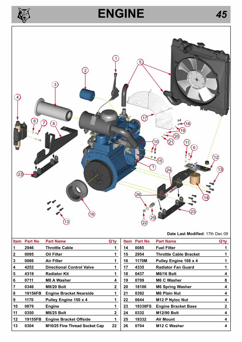
ENGINE 45
Date Last Modified: 17th Dec 09
Item Part No Part Name Q’ty
1 2946 Throttle Cable 1
2 0095 Oil Filter 1
3 0086 Air Filter 1
4 4252 Directional Control Valve 1
5 4319 Radiator Kit 1
6 0711 M8 A Washer 4
7 0346 M8/20 Bolt 2
8 19156FB Engine Bracket Nearside 1
9 1170 Pulley Engine 150 x 4 1
10 0879 Engine 1
11 0350 M8/25 Bolt 2
12 19155FB Engine Bracket Offside 1
13 0304 M10/25 Fine Thread Socket Cap 22
Item Part No Part Name Q’ty
14 0085 Fuel Filter 1
15 2954 Throttle Cable Bracket 1
16 1170M Pulley Engine 168 x 4 1
17 4335 Radiator Fan Guard 1
18 0437 M6/16 Bolt 4
19 0709 M6 C Washer 8
20 18106 M6 Spring Washer 4
21 0392 M6 Plain Nut 4
22 0644 M12 P Nyloc Nut 4
23 18338FS Engine Bracket Base 2
24 0332 M12/90 Bolt 4
25 18332 AV Mount 4
26 0704 M12 C Washer 4
3
4
1
12
11
6
13
5
14
16
67 8
10
15
1
2
13
17
18
19
20
21
x4
23
23
24
26
25
22

ENGINE BAY 46
Date Last Modified: 12th Nov 09
Item Part No Part Name Q’ty
1 2950 Throttle Decal 1
2 18915F Exhaust Muffler Complete 1
3 4320 Reserve Tank 1
4 0344 M8/16 Bolt 2
5 0438 M6/16 Pan Pozi 3
6 0709 M6 C Washer 5
7 0142 M6 P Nyloc Nut 3
8 0066 Pop Rivet 5 x 6 2
9 4088 Catch Plate 1
10 0607FO Access Cover 1
11 17292FO Top Bonnet 1
12 0807 Fuel Pump 1
13 0711 M8 A Washer 14
14 0765O Side Panel 2
15 2836FO Engine Guard Retainer 2
16 4315 In-Line Fuel Filter 1
17 0704 M12 C Washer 14
18 0318 M12/20 Bolt 2
Item Part No Part Name Q’ty
19 0346 M8/20 Bolt 10
20 18580FO Front Engine Bay Guard 1
21 0235 Catch 1
22 0350 M8/25 Bolt 2
23 0712 M8 C Washer 12
24 1757 M8 P Nyloc Nut 6
25 0431 M12/40 Bolt 6
26 1008 Spring Washer 4
27 0476 M8 Plain Nut 4
28 17988 Gasket 3
29 0644 M12 P Nyloc Nut 6
30 0437 M6/16 Bolt 2
31 18581FO Shroud Radiator with Grille 1
32 0067 Pop Rivet 4.8 x 12 2
33 18117 M8/35 Bolt 4
34 18851 Muffler Plate 1
35 19092 Flexi Adaptor 1
15 17 1822
23
26
27
x3 each side
1612
20
24
1
8
9
10
11
2
5
6
7
x3
4
13
314
33
13
34
19
23
13
24
x4
x4
35
13
3637
21 32
19
23
x2
x2
31
30
6
28
19
23
x4
28

FUEL TANK 47
Item Part No Part Name Q’ty
1 1374 Locking Tank Cap 1
2 1658 M6/12 Bolt 10
3 0709 M6 C Washer 10
4 1576FS Tank Top 1
5 18391K Fuel Tank Kit (inc. parts 6 & 7) 1
6 0396 3/8” Dowty Washer 1
7 0211 3/8” Drain Plug 1
Item Part No Part Name Q’ty
8 4087F Tank Strap 1
9 1757 M8 P Nyloc Nut 4
10 0712 M8 C Washer 4
11 0346 M8/20 Bolt 1
12 0351 M8/30 Bolt 1
13 0347 M8/20 Button Head 1
14 18042F Tank Strap (short) 1
1
2
4
5
6
7
Date Last Modified: 5th Dec 07
3
8
910
11
9
10
12
models
with low
funnel only
13
9
models
with high
funnel only
14

FUNNEL (HIGH) 481
7
35
13
9
20
18
19
21
24
23
17
22
10
27
28
11
2
16
12
16
30
31
Date
Last
Mo
dif
ied
: 9th
Oct
08
31
32
3334
25
8
2
14
33
34
15
29
Ite
mP
art
No
Part
Nam
eQ
’ty
12809F
Co
ntr
ol
Bo
x (
deta
il o
n p
ag
es 3
9/4
0)
1
21721
M8/1
0 B
olt
6
34282M
SQ
uic
k R
ele
ase P
ivo
t B
ar
1
40045
M12 T
Nylo
c4
518173
M12/5
5 B
olt
2
64283F
Qu
ick R
ele
ase M
ech
an
ism
1
74238F
OF
un
nel
1
81644
M8 A
nti
-Vib
rati
on
Mo
un
t3
90429
M12/3
5 B
olt
2
10
2919F
OF
eed
Tra
y1
11
2922F
SH
ing
e P
in2
12
0178
Ru
bb
er
En
d S
top
1
13
1600
Nylo
n P
isto
ns
2
14
4342
M8/3
0 C
sk S
oc.
1
Item
Part
No
Part
Nam
eQ
’ty
15
4018S
Pin
Bra
cket
2
16
0712
M8 C
Wash
er
8
17
1603
Die
Sp
rin
gs
2
18
1605M
Sta
inle
ss S
pacer
2
19
1599
Beari
ng
Wash
er
2
20
1570F
RS
afe
ty B
ar
1
21
1348
Lim
it S
wit
ch
1
22
1520
M10/4
5 B
olt
2
23
1591
Nylo
n S
pacer
2
24
0479
M8 P
Nylo
c N
ut
1
25
2727F
SB
racket
Actu
ato
r1
26
4345
M10 P
Nylo
c N
ut
2
27
2986
1/2
” S
pri
ng
Bo
lt2
28
0391
M6 T
Nylo
c N
ut
8
Item
Part
No
Part
Nam
eQ
’ty
29
1236
M6/2
0 B
olt
2
30
0321
M12/3
0 B
olt
4
31
0704
M12 C
Wash
er
12
32
4344
M10 R
ep
air
Wash
er
2
33
0709
M6 C
Wash
er
12
34
0437
M6/1
6 B
olt
10
35
4206
Nylo
n B
ush
1
36
1006
M4/3
0 P
an
Po
zi
2
37
4107F
OR
etr
o H
igh
Fu
nn
el
Bra
cket
1
38
17421
AV
Mo
un
t1
39
M6 A
Wash
er
4
40
0439
M6/2
0 H
ex S
cre
w4
41
2493
Ru
bb
er
Cap
2
42
0481
M8 T
Nylo
c N
ut
1
4
53
6
31
4
36
33
26
16
42
37
38
39 4
0
31
41

FUNNEL (LOW) 49
1
Date Last Modified: 21st May 10
Item Part No Part Name Q’ty
1 See pages 38/39 Control Box 1
2 3008FO Funnel 1
3 18506FR Safety Bar 1
4 0431 M12/40 Bolt 2
5 0704 M12 C Washer 8
6 4116M Spacer Tube 2
7 1599 Bearing Washer 2
Item Part No Part Name Q’ty
8 18173 M12/55 Bolt 2
9 4282MS Quick Release Pivot Bar 1
10 0277 M12/25 Bolt 4
11 4283FO Quick Release Mechanism 1
12 17421 AV Mount 1
13 18507FR Underslung Safety Bar 1
2
3
76
5
4
8
5
9
105
11
12
13

HYDRAULICS (1) 50
Item Part No Part Name Q’ty
1 0161 3/8” - 3/8” Adapter 5
2 0828 3/8” Bulk Head Adapter 2
3 0396 3/8” Dowty Washer 18
4 0026 3/8” - 1/2” Adapter 9
5 0033 1/4” - 3/8” Adapter 2
6 3097 1/2” Hose, 6-way to 4-way valve 1
7 3095 1/2” Hose, 6-way to prop. valve 1
8 3099 1/2” Hose to pump front 1
9 3082 1/4” Hose, cylinder feed 1
10 3083 1/4” Hose, cylinder return 1
Item Part No Part Name Q’ty
11 3084 3/8” Hose to manifold rear 1
12 4000 1/2” Hose to pump rear connection 1
13 3091 3/8” Hose to manifold 1
14 3089 3/8” Hose to bottom of track motor 1
15 3088 3/8” Hose to top of track motor 1
16 4240 1/2” Hose to DCV port ‘P’ 1
17 3096 1/2” Hose, 6-way to prop. valve 1
18 3087 3/8” Hose to top of track motor 1
19 3086 3/8” Hose to bottom of track motor 1
20 3090 3/8” Hose to manifold 1
Date Last Modified: 3rd May 05
1 3
4 3
5 3
3
4
3
3
4
1
3
1
2
2
4
11
9
10
1612
14
15
18
19
20
8
1317
6
7

HYDRAULICS (2) 51
30
2931
32
37
33
27
28
3635
34
Item Part No Part Name Q’ty
1 1913FS Pump Bracket 1
2 0711 M8 A Washer 8
3 2988 M8/90 Bolt 4
4 0429 M12/35 Bolt 2
5 0702 M12 A Washer 4
6 0479 M12 P Nyloc Nut 2
7 0027 1/2” - 1/2” Adapter 2
8 0398 1/2” Dowty Seal 7
9 18893 Hydraulic Pump 1
10 0028 1/2”- 3/4” Adapter 2
11 0479 M8 P Nyloc Nut 4
12 0396 3/8” Dowty Seal 4
13 0026 3/8” - 1/2” Adapter 5
14 0161 3/8” - 3/8” Adapter 3
15 0225 3/4” - 3/8” Adapter 4
16 0152 3/4” Dowty Seal 7
17 1839MA Manifold 1
18 1954 Tank Top Filter 1
19 0100 Filter Element 1
20 0350 M8/25 Bolt 2
21 0712 M8 C Washer 6
Item Part No Part Name Q’ty
22 1658 M6/12 Bolt 8
23 0709 M6 C Washer 8
24 1702FS Tank Top Plate 1
25 2694 3/4” - 1” Adapter 2
26 1703 Hydraulic Tank 1
27 17309 3/8” Hose, DCV to upper motor 1
28 3092 3/8” Hose, motor to motor 1
29 4000 1/2” Hose, pump rear to 6-way valve 1
30 3099 1/2” Hose, pump front to 6-way valve 1
31 3091 3/8” Hose, manifold to LH valve 1
32 3084 3/8” Hose, manifold to 4-port valve 1
33 4258 1” Hose, tank to pump front 1
34 4247 3/8” Hose, manifold to DCV 1
35 3090 3/8” Hose, manifold to RH valve 1
36 3094 3/8” Hose, DCV to lower motor 1
37 4303 1/2” Hose, manifold to hyd filter 1
38 18508 Pump Spline 1
39 0354 M8/60 Bolt 2
40 0479 M8 P Nyloc Nut 2
Date Last Modified: 8th April 10
18
20
21
19
18
22
23
24
10
16
8 13
16
2526
7
8
98
25
1
21
3
4
5
6
112
1213
14
15
10
x4
x2
161712
15
x4
38
39
402

HYDRAULICS (3) 52
Item Part No Part Name Q’ty
1 4059 1/4” Banjo Bolt 4
2 0395 1/4” Dowty Washer 8
3 4046 Hydraulic Cylinders 2
4 4058 1/4” Tee Adapter 2
5 0396 3/8” Dowty Washer 10
6 0033 1/4” - 3/8” Adapter 2
7 4060 3/8” Banjo Bolt 2
8 3086 3/8” Hose, RH lower trk motor - valve 1
9 3081 1/4” Hose, LH track retract 1
Item Part No Part Name Q’ty
10 4031 1/4” Hose, LH track extend 1
11 3080 1/4” Hose, RH track retract 1
12 4032 1/4” Hose, RH track extend 1
13 3083 1/4” Hose, trk extend feed 1
14 3082 1/4” Hose, trk retract feed - valve 1
15 3088 3/8” Hose, LH upper trk motor - valve 1
16 3089 3/8” Hose, LH lower trk motor - valve 1
17 3087 3/8” Hose, RH upper trk motor - valve 1
Date Last Modified: 21st Nov 05
1
2
3
4
56
12
9 10
11
13
14
16
15
8
177
5

ROLLER BOX 53
Item Part No Part Name Q’ty
1 0672 Rollerbox Cover 1
2 18316 M12/50 Csk Bolt 4
3 0481 M8 T Nyloc Nut 3
4 18027M Plate Top Damper Carrier 1
5 0348 M8/20 Csk Socket 1
6 1962FMS Block Top Damped 1
7 18024M Drive Side Plate 1
8 0429 M12/35 Bolt 4
9 0702 M12 A Washer 10
10 18025 Non Drive Side Plate 1
11 1162 Motor Studs 2
12 18028FS Bracket Spring Hanger 2
13 18070 Roller Box Spring 2
14 0305 M10/25 Caphead 2
15 1768 AV Mount 30x30 4
16 0701 M10 A Washer 2
17 0382 M10/30 Bolt 4
18 1361M Drive Spline 1
19 4345 M10 P Nyloc Nut 2
20 2757 Bush Bearing Spline 1
21 0103MH Anvil 1
22 0228M Roller Box 1
Item Part No Part Name Q’ty
23 0985 Straight Grease Nipple 1
24 0986 45o Grease Nipple 1
25 0055 Bearing Boss 2
26 0788 Plastic Bush 2
27 1362M Roller Body 2
28 0325M Roller Blade 12
29 0428 M12/30 Csk Soc. 24
30 4100M Spline 6B Retro Bottom 1
31 4013 Rotor Guard 1
32 0350 M8/25 Bolt 2
33 4068 M10/40 Cap Head Bolt 8
34 0839 M10 C Washer 3
35 0534FS Cover Bracket 1
36 0045 M12 T Nyloc Nut 5
37 0319 M12/220 Bolt 1
38 0356 Funnel Studs M12/50 4
39 2982B Motor 2
40 0476 M8 Plain Nut 2
41 1985 M12/30 Caphead 2
42 0711 M8 A Washer 5
43 0360 M10/25 Bolt 1
Date Last Modified: 16th Sept 10
27
2928
1
8
9
10
2
7
9 8
14
11
16
4
12
15
34
43
9
42
32
19
16
41
21
22
17
23
24
3334
35
37
36
2526
2526
2038
27
18
33
13
28
29
33
13
3
42
6
3039
40
x6
x6
5
x4
9
36
31

ROTOR 54
Item Part No Part Name Q’ty
1 0959 Plastic Cap 1
2 0884MS Bearing Housing Front 1
3 18479K Rotor Nose Shaft Kit 1
4 0880M Rotor 1
5 0491 Bearing 6205 2
6 0883MCB Bearing Cup 1
7 0796 20 Thou Shim As Req’d
8 0701 M10 A Washer 6
9 0900 M10/20 Star Cap Screw 6
Item Part No Part Name Q’ty
10 083MH Cutter Blade 4” 2
11 18275M Blade Pocket 2
12 0386 M10/30 Cap Screw 6
13 1571 Fan Section 2
14 0386 M10/30 Caphead 6
15 18912M Rear Shaft 1
16 4063MCB Bearing Housing Rear 1
17 0495 Bearing 6208 1
Date Last Modified: 10th Sept 09
1
2
3
910
11
12
5
6
4
13
15
16
14
13
17
9
10
12
11
14
7
8
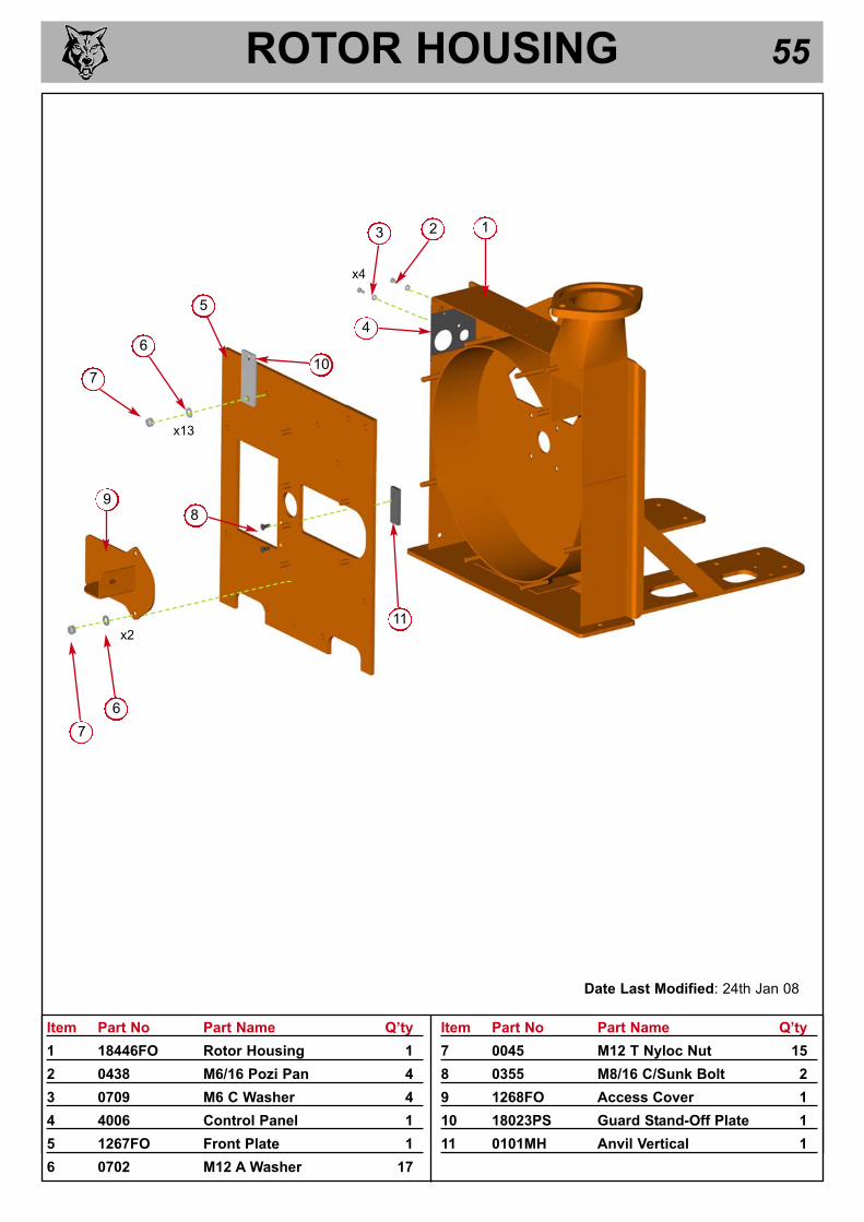
ROTOR HOUSING 55
Item Part No Part Name Q’ty
1 18446FO Rotor Housing 1
2 0438 M6/16 Pozi Pan 4
3 0709 M6 C Washer 4
4 4006 Control Panel 1
5 1267FO Front Plate 1
6 0702 M12 A Washer 17
Item Part No Part Name Q’ty
7 0045 M12 T Nyloc Nut 15
8 0355 M8/16 C/Sunk Bolt 2
9 1268FO Access Cover 1
10 18023PS Guard Stand-Off Plate 1
11 0101MH Anvil Vertical 1
Date Last Modified: 24th Jan 08
5
123
4
6
7
89
7
6
11
x13
x2
x4
10

V-BELT TENSIONING TABLE 56
MET
HO
D:
TIPS
ON
BEL
T TI
GH
TEN
ING
:
13/7
5G18
/100
G12
5PH
150D
H/D
HB
150F
TR15
0VTR
190D
H19
0FTR
190T
DH
190T
FTR
19
0TVG
TR23
0TR
250D
HPT
O10
0PT
O15
0PT
O30
0S4
25/S
426
SHR
EDD
ER
Bel
t Mfr
/ Typ
eG
ates
Sup
er
HC
-MN
Gat
es S
uper
H
C-M
NG
ates
Sup
er
HC
-MN
Gat
es S
uper
H
C-M
NG
ates
Sup
er
HC
-MN
Gat
es S
uper
H
C-M
NG
ates
Sup
er
HC
-MN
Gat
es S
uper
H
C-M
NG
ates
Sup
er
HC
-MN
Gat
es S
uper
H
C-M
NG
ates
Sup
er
HC
-MN
Gat
es Q
uad
Pow
er II
Gat
es S
uper
H
C-M
NG
ates
Sup
er
HC
-MN
N/A
Gat
es S
uper
H
C-M
N
Bel
t Pitc
h D
esig
natio
nS
PA
SP
AS
PA
SP
AS
PA
SP
AS
PA
SP
AS
PA
SP
AS
PB
XP
BS
PA
SP
AS
PB
Bel
t Len
gth
900.
010
60.0
1060
.010
60.0
1060
.010
60.0
1232
.012
32.0
1232
.012
32.0
1950
.033
50.0
900.
090
0.0
2120
.0
Bel
t def
lect
ion
=h
4.0
4.0
4.0
4.0
4.0
4.0
4.0
4.0
4.0
4.0
6.0
10.0
4.0
4.0
8.0
3.4
- 3.6
3.1
- 3.3
3.0
- 3.2
4.3
- 4.5
4.3
- 4.5
4.3
- 4.5
3.3
- 3.5
3.3
- 3.5
3.9
- 4.1
3.9
- 4.1
3.4
- 3.6
3.5
- 3.7
*3.
3 - 3
.53.
8 - 4
.03.
3 - 3
.5*
3.0
- 3.2
2.8
- 3.0
2.7
- 2.9
3.7
- 4.0
3.7
- 4.0
3.7
- 4.0
2.8
- 3.0
2.8
- 3.0
3.4
- 3.6
3.4
- 3.6
3.0
- 3.2
3.1
- 3.3
*2.
9 - 3
.03.
3 - 3
.52.
9 - 3
.1*
Bel
t Mfr
/ Typ
eN
/AN
/AG
ates
Sup
er
HC
-MN
N/A
Gat
es S
uper
H
C-M
NG
ates
Sup
er
HC
-MN
N/A
Gat
es S
uper
H
C-M
NN
/AG
ates
Sup
er
HC
-MN
Gat
es S
uper
H
C-M
NN
/AN
/AG
ates
Sup
er
HC
-MN
Gat
es S
uper
H
C-M
NN
/A
Bel
t Pitc
h D
esig
natio
nS
PA
SP
AS
PA
SP
AS
PA
SP
AS
PA
SP
A
Bel
t Len
gth
950.
090
0.0
900.
092
5.0
925.
095
0.0
950.
010
00.0
Bel
t def
lect
ion
=h
4.0
4.0
4.0
4.0
4.0
4.0
4.0
4.0
1.9
- 2.0
2.3
- 2.4
2.3
- 2.4
2.3
- 2.4
2.3
- 2.4
1.5
- 1.6
2.0
- 2.2
1.9
- 2.0
1.7
- 1.8
2.0
- 2.1
2.0
- 2.1
2.0
- 2.2
2.0
- 2.2
1.3
- 1.4
1.8
- 2.0
1.7
- 1.8
* D
UE
TO
TH
E E
XTE
ND
ED
BE
LT S
PA
N L
EN
GTH
S O
N T
HE
250
DH
& S
425/
S42
6 S
HR
ED
DE
R, T
HE
FO
RC
E R
EA
DIN
GS
AR
E IN
CR
EA
SE
D B
Y 0
.5K
gf O
VE
R T
HE
DE
SIG
N IQ
OU
TPU
TS
Forc
e re
adin
g (K
gf)
New
bel
t
Use
d be
lt
TW M
OD
EL N
o.:
PUMP BELT
Use
d be
lt
Forc
e re
adin
g (K
gf)
ROTOR BELTS
TIM
BER
WO
LF V
-BEL
T TE
NSI
ON
ING
DA
TA T
AB
LE
1. S
ET T
HE
DEF
LEC
TIO
N D
ISTA
NC
E O
N T
HE
LOW
ER S
CA
LE O
F TH
E TE
NSI
ON
GU
AG
E
SO
TH
AT
THE
UN
DER
SID
E O
F TH
E 'O
'-RIN
G E
QU
ALS
TH
E 'h
' VA
LUE
GIV
EN IN
TH
E
TA
BLE
BEL
OW
2. E
NSU
RE
THA
T TH
E D
EFLE
CTI
ON
FO
RC
E SC
ALE
IS Z
ERO
'D B
Y PU
SHIN
G T
HE
UPP
ER
'O'-R
ING
ALL
TH
E W
AY
DO
WN
3. P
LAC
E TH
E TE
NSI
ON
GU
AG
E IN
TH
E C
ENTR
E O
F TH
E B
ELT
SPA
N A
S SH
OW
N IN
T
HE
DIA
GR
AM
LEF
T
4. P
RES
S D
OW
NW
AR
DS
ON
TH
E R
UB
BER
BU
FFER
, DEF
LEC
TIN
G T
HE
BEL
T U
NTI
L TH
E
UN
DER
SID
E O
F TH
E LO
WER
O'-R
ING
IS L
EVEL
WIT
H T
HE
BEL
T B
EHIN
D (U
SE A
S
TRA
IGH
T ED
GE
IF T
HER
E IS
ON
LY 1
BEL
T)
5. T
AK
E TH
E R
EAD
ING
FR
OM
TH
E D
EFLE
CTI
ON
SC
ALE
OF
THE
TEN
SIO
N M
ETER
(R
EAD
AT
THE
LOW
ER E
DG
E O
F TH
E 'O
'-RIN
G) &
CO
MPA
RE
THIS
VA
LUE
WIT
H
TH
AT
GIV
EN IN
TH
E TA
BLE
BEL
OW
6. T
IGH
TEN
OR
LO
OSE
N B
ELTS
AS
REQ
UIR
ED F
OLL
OW
ING
PR
OC
EDU
RE
GIV
EN IN
TH
E
OPE
RA
TOR
'S M
AN
UA
L
TEN
SIO
N G
UA
GES
AR
E A
VAIL
AB
LE F
RO
M T
IMB
ERW
OLF
SPA
RES
, QU
OTI
NG
PA
RT
No.
180
91
New
bel
t
A) T
HER
E W
ILL
NO
RM
ALL
Y B
E A
RA
PID
DR
OP
IN T
ENSI
ON
DU
RIN
G T
HE
R
UN
-IN P
ERIO
D F
OR
NEW
BEL
TS. W
HEN
NEW
BEL
TS A
RE
FITT
ED, C
HEC
K T
HE
T
ENSI
ON
EVE
RY
2-3
HO
UR
S &
AD
JUST
UN
TIL
THE
TEN
SIO
N R
EMA
INS
C
ON
STA
NT
B) T
HE
BES
T TE
NSI
ON
FO
R V
-BEL
T D
RIV
ES IS
TH
E LO
WES
T TE
NSI
ON
AT
W
HIC
H T
HE
BEL
TS D
O N
OT
SLIP
OR
RA
TCH
ET U
ND
ER T
HE
HIG
HES
T LO
AD
C
ON
DIT
ION
C) T
OO
MU
CH
TEN
SIO
N S
HO
RTE
NS
BEL
T &
BEA
RIN
G L
IFE
D) T
OO
LIT
TLE
TEN
SIO
N W
ILL
AFF
ECT
THE
PER
FOR
MA
NC
E O
F YO
UR
MA
CH
INE
E
SPEC
IALL
Y IN
RES
PEC
T O
F N
O-S
TRES
S D
EVIC
ES
E) E
NSU
RE
THA
T B
ELT
DR
IVES
AR
E K
EPT
FREE
OF
AN
Y FO
REI
GN
MA
TER
IALS
F) IF
A B
ELT
SLIP
S - T
IGH
TEN
IT!
=
=
h
Ver
2.0
- 12
-10-
07