section 8.0 – streets table of contents
TRANSCRIPT

SECTION 8.0 – STREETS TABLE OF CONTENTS
SECTION 8.0 STREETS................................................................................................ 2 8.1 INTRODUCTION.................................................................................................. 2 8.2 FUNCTION OF STREETS IN THE DRAINAGE SYSTEM ................................... 2 8.3 STREET CLASSIFICATIONS AND CAPACITY LIMITATIONS .......................... 2
8.3.1 STREET CLASSIFICATIONS .......................................................................................2 Table 8.3.1 – City of Greeley Street Classifications ..............................................................2
8.3.2 STREET CAPACITY - INITIAL STORM........................................................................3 Table 8.3.2 – Street Capacity – Initial Storm -- Minor Storm .................................................3
8.3.3 STREET CAPACITY - MAJOR STORM .......................................................................4 Table 8.3.3 – Street Capacity for Major Storm Runoff ...........................................................4
8.4 HYDRAULIC EVALUATION FOR STREET CAPACITY ..................................... 4 8.4.1 ALLOWABLE STREET CAPACITY - INITIAL STORMS...............................................4 8.4.2 ALLOWABLE STREET CAPACITY - MAJOR STORMS ..............................................5 8.4.3 RURAL STREETS (LOCAL, LOW-VOLUME STREETS WITHOUT CURB AND GUTTER) ..................................................................................................................................6
8.5 ALLOWABLE STREET CROSS-FLOW CONDITIONS....................................... 6 8.5.1 CROSS STREET FLOW AT INTERSECTIONS ...........................................................6
Table 8.5.1 – Allowable Cross-Street Flow at Intersections ..................................................6 8.5.2 STREET OVERTOPPING.............................................................................................6
Table 8.5.2 – Allowable Culvert Overtopping ........................................................................7 8.6 DESIGN EXAMPLE – Determination of street capacity ................................... 7 8.7 CHECKLIST......................................................................................................... 8
Section 8 – Page 1

SECTION 8.0 STREETS
8.1 INTRODUCTION The criteria presented in this section shall be used in the evaluation of the allowable drainage encroachment within public streets. The review of all submittals shall be based on the criteria herein.
8.2 FUNCTION OF STREETS IN THE DRAINAGE SYSTEMUrban and rural streets, specifically the curb and gutter or the roadside ditches, are part of the storm drainage system. When the drainage in the street exceeds allowable limits, a storm drain system or an open channel is required to convey the excess flows. However, the primary func-tion of the urban street system is for traffic movement, and, therefore, the drainage function is secondary and must not interfere with the traffic function of the street.
Design criteria for collecting and moving runoff water on public streets are based on a reason-able frequency and magnitude of traffic interference. Depending on the character of the street, certain traffic lanes can be inundated during specific design storm runoff events. The primary function of the streets during the initial storm runoff event is to convey the nuisance flows quickly and efficiently to the storm drain or open channel drainage without interference with traf-fic movement. During the major storm runoff event the function of the streets is to provide a passageway for the flood flows with minimal damage to the urban environment, and passage of emergency vehicles.
8.3 STREET CLASSIFICATIONS AND CAPACITY LIMITATIONS8.3.1 STREET CLASSIFICATIONS The streets in the City are classified for drainage use according to the average daily traffic (ADT) for which the street is designed and the adopted City classifications. The larger the ADT, the more restrictive the allowable drainage encroachment into the driving lanes is. Re-fer to the City of Greeley Standard Details and "Street Design Criteria" for specific dimen-sions and cross sections of each street classification. The adopted City classifications are summarized in the following table:
TABLE 8.3.1 – CITY OF GREELEY STREET CLASSIFICATIONS
CITY OF GREELEY STREET CLASSIFICATIONS
Classification
Width (Flow line to Flow line)
City of Greeley Standard Detail
No.*
Local - Low Volume*
No Curb & Gutter Shoulder Only w/Ditch
S-1
Local – Commercial / Industrial &
Residential
40'
S-2
Local – Performance
Option 14
34'
S-2-14
Section 8 – Page 2

Minor Collector
52'
S-3
Major Collector
64'
S-4
Minor Arterial
64'
S-5
Major Arterial
(with Raised Median)
2 Lanes at 33' each
S-6
* Reference: See City of Greeley Street Design Criteria Manual for Standard Detail Nos. S-1 to S-6 plus street options.
8.3.2 STREET CAPACITY - INITIAL STORM The street capacity for initial storm runoff events is determined by the limitations set forth be-low:
TABLE 8.3.2 – STREET CAPACITY – INITIAL STORM -- MINOR STORM
STREET CAPACITY FOR INITIAL STORM or MINOR STORM RUNOFF
Street Classification
Curb Overtop-ping Allowed
Maximum Pavement Encroach-ment
Local1 Low Volume
No
Flow may spread to crown of street
Local Commercial / Industrial &
Residential & Performance Option 14 w/ vertical curb
No
Flow may spread to crown of street
Local Commercial / Industrial &
Residential & Performance Option 14 w/ rollover curb
Yes
5” max above gut-ter FL
Flow may spread to crown of street
Minor Collector
No
Flow must leave a minimum 10' wide center lane open
Major Collector
No
Flow must leave a minimum 10' wide center lane open
Minor Arterial
No
Flow must leave a minimum of one traffic lane open each direction
Section 8 – Page 3

Major Arterial
No
Flow must leave a minimum of one traffic lane open each direction
*Note:
1For Local - Low Volume Streets see Section 5.4 of these Criteria for the design and capacity of roadside ditches.
8.3.3 STREET CAPACITY - MAJOR STORM The street capacity during major storm events is determined by the limitations set forth be-low:
TABLE 8.3.3 – STREET CAPACITY FOR MAJOR STORM RUNOFF
STREET CAPACITY FOR MAJOR STORM RUNOFF1
Street Classification
Maximum Depth At
Gutter Flow line
Maximum Depth at Crown
Allowable Inunda-
tion Local2, Local Commer-cial / Industrial / Resi-
dential / Option 14
18"
N/A
No inundation at
groundline3
Collector
18”
N/A
No inundation at groundline3
Arterial
18"
6"
No inundation at
groundline3
Notes:
1Most restrictive condition shall control design 2For Local - Low Volume Streets see Section 5.4 of these Criteria for the design and capacity of roadside ditches. 3Includes inundation of residential dwellings, public, commercial and industrial build-ings
8.4 HYDRAULIC EVALUATION FOR STREET CAPACITY 8.4.1 ALLOWABLE STREET CAPACITY - INITIAL STORMS The determination of the Allowable Street Capacity shall be based on the following proce-dure: determine the Theoretical Capacity based on the street cross section; compute the street flow; then, apply the appropriate reduction factor to calculate the Allowable Street Ca-pacity.
Based on the Maximum Pavement Encroachment for the various street classifications pre-sented in Section 8.3, the Theoretical Capacity of each street section is calculated using the Modified Manning's formula shown below:
Section 8 – Page 4

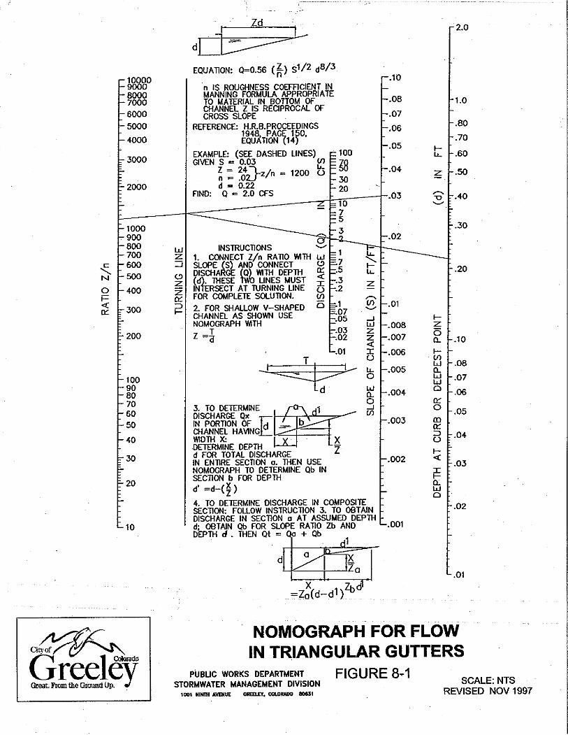
Q = (0.56) (Z/n)S1/2d8/3 Equation 8.4.1 Where: Q = discharge in cfs
Z = 1/Sx, where Sx is the cross slope of the pavement (ft/ft) d = depth of water at face of curb (feet) S = longitudinal grade of street (ft/ft) n = Manning's roughness coefficient
Note: This equation does not pertain to streets with borrow ditches. Also, the solution to the above equation can be obtained through the use of the nomograph (Figure 8-1 and included for information only).
The Allowable Capacity of a Street Section is then calculated by multiplying the Theoretical Capacity by the appropriate reduction factor found in Figure 8-2. The purpose of the reduc-tion factor is to account for various street conditions, which decrease the street capacity. These conditions may include street overlays, parked vehicles, debris and hail accumula-tion, and deteriorated pavement.
The Designer will find the Allowable Street Capacity already calculated in Table 8-1 for sev-eral of the standard, symmetrical street sections. The calculations were performed for vari-ous allowable flow depths and street slopes. A Manning’s n-value of 0.016 was used for the calculations at all street slopes.
Other accepted street options used within the City are not included in the Figures and Ta-bles. The Designer shall calculate the Theoretical Capacity using equation 8.4.1, then calcu-late the Allowable Street Capacity by multiplying the Theoretical Capacity obtained, by the appropriate reduction factor found in Figure 8-2. These street options shall meet the re-quirements specified in the Street Capacity for Initial Storm Runoff depending on ADT and Street Classification (Contact Traffic Division for this information). These calculations shall be included in the Drainage Report.
The Allowable Street Capacity will also need to be reduced if non-symmetrical street sec-tions are encountered. Street capacity calculations at critical locations of non-symmetrical street sections shall be submitted in the Drainage Report.
8.4.2 ALLOWABLE STREET CAPACITY - MAJOR STORMS The street capacity for the major storm is determined by the depth and inundation limits set forth in Section 8.3.3. The Allowable Street Capacity is found by using the same procedure outlined in Section 8.4.1 with one exception due to the addition of grass areas. A weighted Manning’s n for the entire roadway cross-section will be used in Equation 8.4.1 to find the maximum theoretical flowrate – Q.
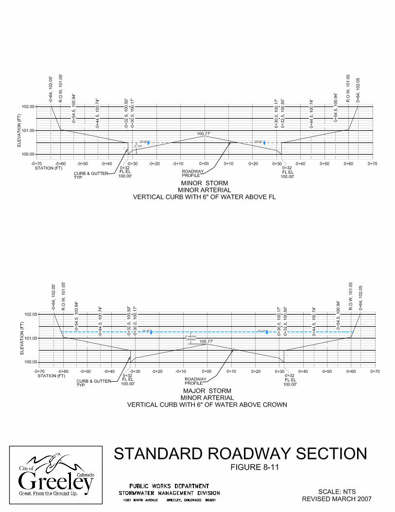
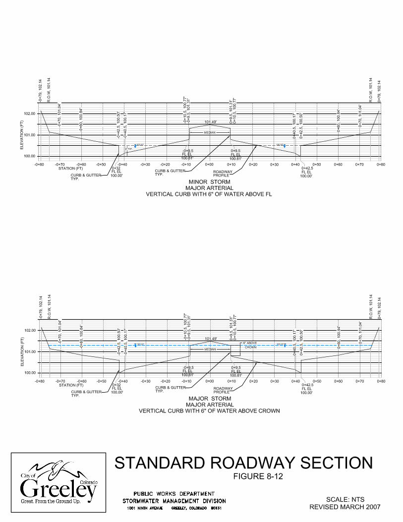
Again, the Designer will find the Allowable Street Capacity already calculated in Table 8-1 for several of the City’s standard, symmetrical street sections. A Manning’s value of 0.016 for the pavement and sidewalk areas and 0.033 for the grass area was used to determine capacity. The maximum allowable depth at the gutter flowline is 18 inches. The street ca-pacity criteria for both the initial and major storms are graphically displayed by Figures 8-3 and 8-4.
Section 8 – Page 5
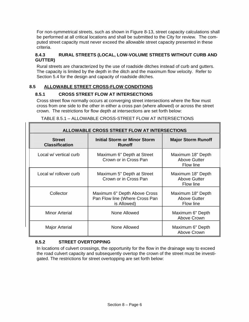
For non-symmetrical streets, such as shown in Figure 8-13, street capacity calculations shall be performed at all critical locations and shall be submitted to the City for review. The com-puted street capacity must never exceed the allowable street capacity presented in these criteria.
8.4.3 RURAL STREETS (LOCAL, LOW-VOLUME STREETS WITHOUT CURB AND GUTTER) Rural streets are characterized by the use of roadside ditches instead of curb and gutters. The capacity is limited by the depth in the ditch and the maximum flow velocity. Refer to Section 5.4 for the design and capacity of roadside ditches.
8.5 ALLOWABLE STREET CROSS-FLOW CONDITIONS8.5.1 CROSS STREET FLOW AT INTERSECTIONS Cross street flow normally occurs at converging street intersections where the flow must cross from one side to the other in either a cross pan (where allowed) or across the street crown. The restrictions for flow depth at intersections are set forth below:
TABLE 8.5.1 – ALLOWABLE CROSS-STREET FLOW AT INTERSECTIONS
ALLOWABLE CROSS STREET FLOW AT INTERSECTIONS
Street Classification
Initial Storm or Minor Storm
Runoff
Major Storm Runoff
Local w/ vertical curb
Maximum 6" Depth at Street
Crown or in Cross Pan
Maximum 18" Depth
Above Gutter Flow line
Local w/ rollover curb
Maximum 5" Depth at Street
Crown or in Cross Pan
Maximum 18" Depth
Above Gutter Flow line
Collector
Maximum 6" Depth Above Cross Pan Flow line (Where Cross Pan
is Allowed)
Maximum 18" Depth
Above Gutter Flow line
Minor Arterial
None Allowed
Maximum 6" Depth
Above Crown
Major Arterial
None Allowed
Maximum 6" Depth Above Crown
8.5.2 STREET OVERTOPPING In locations of culvert crossings, the opportunity for the flow in the drainage way to exceed the road culvert capacity and subsequently overtop the crown of the street must be investi-gated. The restrictions for street overtopping are set forth below:
Section 8 – Page 6

TABLE 8.5.2 – ALLOWABLE CULVERT OVERTOPPING
ALLOWABLE CULVERT OVERTOPPING
Street Classifica-tion
10-Year Storm
Maximum Depth
Major Storm Maximum Depth1.
Local
None
18" At The Gutter Flow line
Local w/Roadside
Ditch
None
6" At The Street Crown
Collector & Minor Arterial
None
6" At The Street Crown
Major Arterial
None
No Overtopping Allowed
For bridges the minimum clearance be-tween the low chord and the EGL shall be
6". 1. The maximum headwater for the 100-year design flows shall be 1.5 times the culvert diameter or 1.5
times the rise dimension for pipe shapes other than round.
8.6 DESIGN EXAMPLE – DETERMINATION OF STREET CAPACITYGIVEN:
Street with a traffic classification of "Minor Collector" and a slope of 1.0 percent.
FIND:
Maximum allowable capacity for initial and major storm.
SOLUTION:
STEP 1: Determine the allowable depth: From Section 8.3, for a Minor Collector, the maximum depth at the curb (without overtop-ping) would be 6" for the initial storm.
STEP 2: Determine the allowable initial storm gutter capacity:
From Table 8-1, for a "Minor Collector" with an allowable depth of 0.50 feet and a slope of 1.0 percent, read the allowable gutter capacity of 8.6 cfs.
STEP 3: Determine the allowable major storm street capacity: From Table 8-1, for a "Minor Collector" with a slope of 1.0 percent, read the allowable ca-pacity of 610 cfs for the full street section, assuming the street is symmetrical.
Section 8 – Page 7
8.7 CHECKLISTTo aid the Designer and Reviewer, the following checklist has been prepared:
1. Determine the street classification first and then the allowable flow depth and gutter capac-ity.
2. Use the flattest street slope to determine the gutter capacity.
3. To calculate the allowable street flow, use the appropriate reduction factor (F) to calculate the allowable gutter capacity.
4. Check for non-symmetrical street evaluation.
5. Check for cross-flow conditions at intersections and allowable culvert overtopping depths.
6. Storm drains required when gutter capacity is exceeded.
7. Check adequacy of downstream facilities.
Section 8 – Page 8

Local-Residential w/ 3-3/8" tall rollover curbReduction Factors Initial Storm (half street) Major Storm (full street)
Gutter (from Figure 8-2) Theoretical Allowable Theoretical AllowableSlope Initial Storm Major Storm Capacity Capacity Capacity Capacity
w/ 5" of water w/ 5" of waterabove flow above flow
line line(ft/ft) (cfs) (cfs) (cfs) (cfs)0.004 0.500 0.500 5.8 2.9 459 2300.005 0.650 0.650 6.5 4.2 514 3340.006 0.800 0.800 7.1 5.7 563 4500.008 0.800 0.800 8.2 6.6 650 5200.009 0.800 0.800 8.7 7.0 689 5510.010 0.800 0.800 9.2 7.4 726 5810.020 0.800 0.700 13.0 10.4 1027 7190.040 0.610 0.500 18.4 11.2 1453 7270.060 0.410 0.375 22.6 9.3 1779 6670.080 0.280 0.270 26.1 7.3 2054 555
Local-Commercial / Industrial & Residential w/ vertical curbReduction Factors Initial Storm (half street) Major Storm (full street)
Gutter (from Figure 8-2) Theoretical Allowable Theoretical AllowableSlope Initial Storm Major Storm Capacity Capacity Capacity Capacity(ft/ft) (cfs) (cfs) (cfs) (cfs)0.004 0.500 0.500 6.9 3.5 386 1930.005 0.650 0.650 7.7 5.0 432 2810.006 0.800 0.800 8.4 6.7 473 3780.008 0.800 0.800 9.7 7.8 547 4380.009 0.800 0.800 10.3 8.2 580 4640.010 0.800 0.800 10.8 8.6 611 4890.020 0.800 0.700 15.3 12.2 864 6050.040 0.610 0.500 21.7 13.2 1222 6110.060 0.410 0.375 26.6 10.9 1497 5610.080 0.280 0.270 30.7 8.6 1728 467
Minor CollectorReduction Factors Initial Storm (half street) Major Storm (full street)
Gutter (from Figure 8-2) Theoretical Allowable Theoretical AllowableSlope Initial Storm Major Storm Capacity Capacity Capacity Capacity(ft/ft) (cfs) (cfs) (cfs) (cfs)0.004 0.500 0.500 6.8 3.4 482 2410.005 0.650 0.650 7.6 4.9 539 3500.006 0.800 0.800 8.4 6.7 591 4730.008 0.800 0.800 9.7 7.8 682 5460.009 0.800 0.800 10.2 8.2 724 5790.010 0.800 0.800 10.8 8.6 763 6100.020 0.800 0.700 15.3 12.2 1079 7550.040 0.610 0.500 21.6 13.2 1525 7630.060 0.410 0.375 26.4 10.8 1868 7010.080 0.280 0.270 30.5 8.5 2157 582
TABLE 8-1City of Greeley - Standard Street Section Capacities Revised March 2007

Major CollectorReduction Factors Initial Storm (half street) Major Storm (full street)
Gutter (from Figure 8-2) Theoretical Allowable Theoretical AllowableSlope Initial Storm Major Storm Capacity Capacity Capacity Capacity(ft/ft) (cfs) (cfs) (cfs) (cfs)0.004 0.500 0.500 6.8 3.4 527 2640.005 0.650 0.650 7.6 4.9 589 3830.006 0.800 0.800 8.4 6.7 646 5170.008 0.800 0.800 9.7 7.8 745 5960.009 0.800 0.800 10.2 8.2 791 6330.010 0.800 0.800 10.8 8.6 833 6660.020 0.800 0.700 15.3 12.2 1179 8250.040 0.610 0.500 21.6 13.2 1667 8340.060 0.410 0.375 26.4 10.8 2041 7650.080 0.280 0.270 30.5 8.5 2357 636
Minor ArterialReduction Factors Initial Storm (half street) Major Storm (full street)
Gutter (from Figure 8-2) Theoretical Allowable Theoretical AllowableSlope Initial Storm Major Storm Capacity Capacity Capacity Capacity(ft/ft) (cfs) (cfs) (cfs) (cfs)0.004 0.500 0.500 6.8 3.4 339 1700.005 0.650 0.650 7.6 4.9 379 2460.006 0.800 0.800 8.4 6.7 416 3330.008 0.800 0.800 9.7 7.8 480 3840.009 0.800 0.800 10.2 8.2 509 4070.010 0.800 0.800 10.8 8.6 537 4300.020 0.800 0.700 15.3 12.2 759 5310.040 0.450 0.450 21.6 9.7 1073 4830.060 0.275 0.275 26.4 7.3 1315 3620.080 0.175 0.175 30.5 5.3 1518 266
Major ArterialReduction Factors Initial Storm (half street) Major Storm (full street)
Gutter (from Figure 8-2) Theoretical Allowable Theoretical AllowableSlope Initial Storm Major Storm Capacity Capacity Capacity Capacity(ft/ft) (cfs) (cfs) (cfs) (cfs)0.004 0.500 0.500 6.8 3.4 367 1840.005 0.650 0.650 7.6 4.9 410 2670.006 0.800 0.800 8.4 6.7 450 3600.008 0.800 0.800 9.7 7.8 519 4150.009 0.800 0.800 10.2 8.2 551 4410.010 0.800 0.800 10.8 8.6 581 4650.020 0.800 0.700 15.3 12.2 821 5750.040 0.450 0.450 21.6 9.7 1161 5220.060 0.275 0.275 26.4 7.3 1422 3910.080 0.175 0.175 30.5 5.3 1642 287
TABLE 8-1ACity of Greeley - Standard Street Section Capacities Revised March 2007
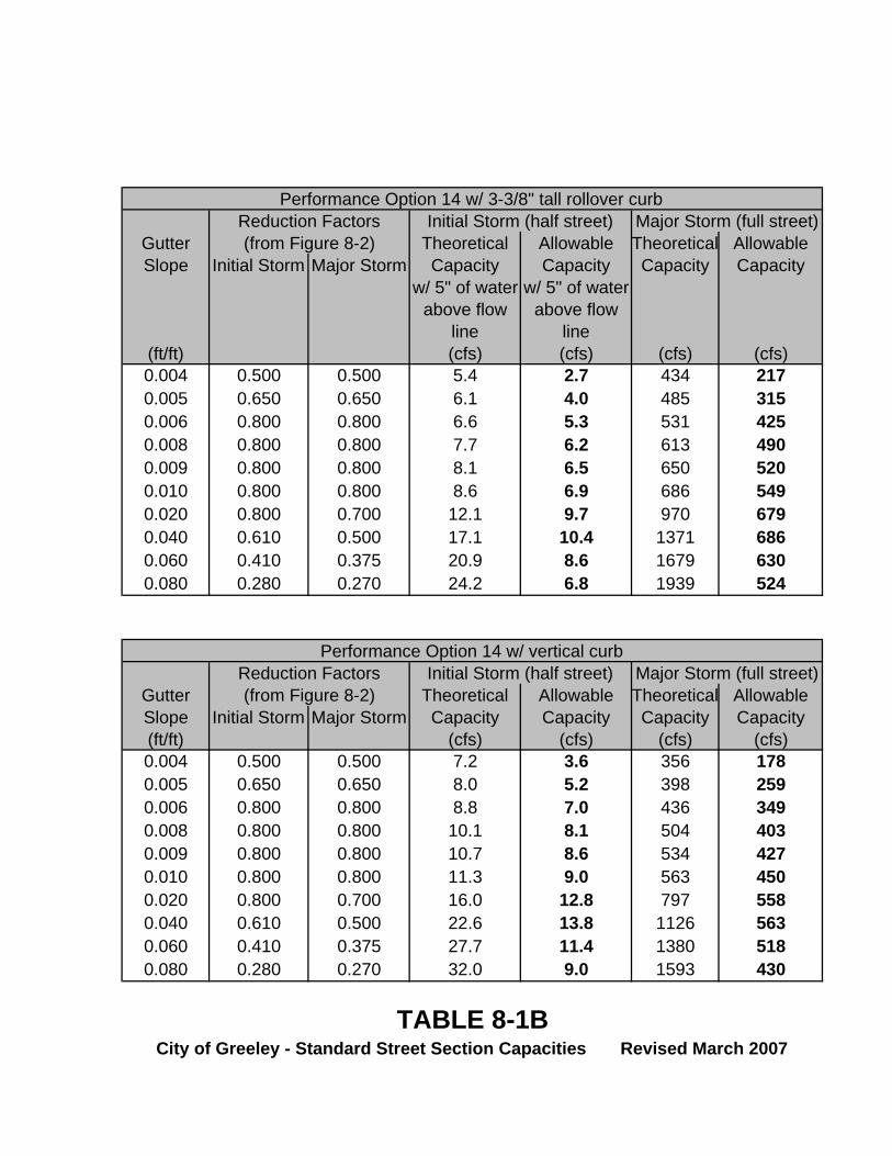
Performance Option 14 w/ 3-3/8" tall rollover curbReduction Factors Initial Storm (half street) Major Storm (full street)
Gutter (from Figure 8-2) Theoretical Allowable Theoretical AllowableSlope Initial Storm Major Storm Capacity Capacity Capacity Capacity
w/ 5" of water w/ 5" of waterabove flow above flow
line line(ft/ft) (cfs) (cfs) (cfs) (cfs)0.004 0.500 0.500 5.4 2.7 434 2170.005 0.650 0.650 6.1 4.0 485 3150.006 0.800 0.800 6.6 5.3 531 4250.008 0.800 0.800 7.7 6.2 613 4900.009 0.800 0.800 8.1 6.5 650 5200.010 0.800 0.800 8.6 6.9 686 5490.020 0.800 0.700 12.1 9.7 970 6790.040 0.610 0.500 17.1 10.4 1371 6860.060 0.410 0.375 20.9 8.6 1679 6300.080 0.280 0.270 24.2 6.8 1939 524
Performance Option 14 w/ vertical curbReduction Factors Initial Storm (half street) Major Storm (full street)
Gutter (from Figure 8-2) Theoretical Allowable Theoretical AllowableSlope Initial Storm Major Storm Capacity Capacity Capacity Capacity(ft/ft) (cfs) (cfs) (cfs) (cfs)0.004 0.500 0.500 7.2 3.6 356 1780.005 0.650 0.650 8.0 5.2 398 2590.006 0.800 0.800 8.8 7.0 436 3490.008 0.800 0.800 10.1 8.1 504 4030.009 0.800 0.800 10.7 8.6 534 4270.010 0.800 0.800 11.3 9.0 563 4500.020 0.800 0.700 16.0 12.8 797 5580.040 0.610 0.500 22.6 13.8 1126 5630.060 0.410 0.375 27.7 11.4 1380 5180.080 0.280 0.270 32.0 9.0 1593 430
TABLE 8-1BCity of Greeley - Standard Street Section Capacities Revised March 2007