section 7 - timberpro inctimberpro.com/operator/830aops/014.pdfwheel drive circuit - tests &...
TRANSCRIPT
Wheel Drive Circuit - Tests & Adjustments7.2.1Form T014
Section 7.2
Wheel Drive Circuit - Tests & Adjustments
Safety Information. . . . . . . . . . . . . . . . . . . . . . . . . . . . . . . . . . . . . . . . . 7.2.2
Tools Required . . . . . . . . . . . . . . . . . . . . . . . . . . . . . . . . . . . . . . . . . . . 7.2.2
Wheel Drive Pump: Wheel Drive Charge Pressure . . . . . . . . . . . . . . . . . . . . . . . . . . . . 7.2.3 Wheel Drive Pump Directional Relief Pressure . . . . . . . . . . . . . . . 7.2.4 Wheel Drive Pump POR Pressure . . . . . . . . . . . . . . . . . . . . . . . . . 7.2.6 Wheel Drive Pump Null . . . . . . . . . . . . . . . . . . . . . . . . . . . . . . . . . . 7.2.8 Wheel Drive Pump Case Drain Pressure . . . . . . . . . . . . . . . . . . . . 7.2.10
Wheel Drive Motor: Wheel Drive Motor Begin Of Stroke . . . . . . . . . . . . . . . . . . . . . . . . 7.2.11 Wheel Drive Motor Case Drain Pressure . . . . . . . . . . . . . . . . . . . . 7.2.14 Wheel Drive Motor Case Drain Flow. . . . . . . . . . . . . . . . . . . . . . . . 7.2.15

Wheel Drive Circuit - Tests & Adjustments 7.2.2 Form T014
Safety information
You must read and understand the warnings and basic safety rules, found in Group-1 of the Operation & Maintenance manual, before performing any operation, test or adjustment procedures.
Tools Required• Tachometer • 0 - 60 psi (0 - 1000 kPa) pressure gauge • 0 - 600 psi (0 - 5 Mpa) pressure gauge • 0 - 6000 psi (0 - 50 Mpa) pressure gauge • 0 - 10,000 psi (0 - 80 Mpa) pressure gauge • 9/16”, 5/8”, 11/16”, 3/4”, 7/8”, 13/16”, 15/16”, 1-1/4”, & 1-3/8” wrenches • 5/32” & 1/4” allen wrenches • 10mm, 13mm, 17mm, 24mm wrenches • 3mm, 4mm, 5mm, 8mm allen wrenches • (2) PN# 15869, TIMBCO quick-couple adapter • PN# 16031, #4 ORS plug • PN# 16032, #8 ORS plug • PN# 15176, #4 ORS run tee • Gauge test hose • (2) Gauge test hose w/#4 JICF ends • #8 test hose w/#8 ORSF ends • 24” (61cm) jumper hose w/#4 JICM ends • (2) #6 ORBM - #4 JICM adapter • #12 ORBM - #4 JICM adapter • Calibrated container - 10 gallons (38 litres) • Stop watch
• The operator or another mechanic may be required to operate a control while a pressure reading is being taken.
NOTE: Each machine is shipped from the factory with at least one 600 psi and one 10,000 psi gauge with quick-couple adapters. The gauges can be found in the machine Up-Time Kit.
At operating temperature, the engine, exhaust system components, cooling system components and hydraulic system components are HOT. Any contact can cause severe burns.
00017
Diesel exhaust fumes contain elements that are hazardous to your health. Always run engine in a well ventilated area. If in an enclosed space, vent exhaust to the outside.
00015

Wheel Drive Circuit - Tests & Adjustments7.2.3Form T014
Wheel Drive Charge Pressure Specification:
DO NOT set charge pressure above 450 psig (31 bar). Overheating of the circuit and damage to the system can result.
425 psig (29.3 bar)
Test Standards:
• Hydraulics at operating temperature of 140°F (60°C) or greater.
• Engine operating at high idle (approx. 1500 RPM).
Procedure:
1. Ensure the hydraulics are at correct operating temperature.
2. Start the engine and run at low idle.
3. Connect the 600 psi pressure gauge, with the quick-couple adapter attached, to the gauge port tap provided on the centralized pressure check manifold. See Figure 1.
NOTE: Only install a 600 psi pressure gauge after the engine is running. If the gauge is installed before the engine is started it can be damaged.
6. Increase engine throttle to high idle (approx. 1500 RPM).
7. Read the pressure gauge, the wheel drive charge pressure should be set at 425 psig (29.3 bar).
If wheel drive charge pressure setting is correct, go to step #10. If adjustment is required, continue with step #8.
8. Open the rear engine guard and locate the wheel drive charge pressure manifold assembly. See Figure 2.
9. Locate the large charge pressure relief cartridge. See Figure 2. Use the 9/16” wrench and 5/32” allen wrench to loosen the jam nut.
Turning the adjustment setscrew CLOCKWISE increases the pressure setting. Turning the setscrew COUNTER-CLOCKWISE decreases the pressure setting.
10. Read the pressure gauge, re-adjust pressure setting as required. After the correct pressure setting is made, tighten the jam nut to lock adjustment setting.
11. Shut down the engine. Remove the pressure gauge and secure the rear engine guard.
Figure 2: Wheel Drive Charge Pressure Manifold (Shown With Optional Charge Heater Installed)
T00026
Figure 1: Wheel Drive Charge Pressure Gauge Port Tap
T00026

Wheel Drive Circuit - Tests & Adjustments 7.2.4 Form T014
Wheel Drive Pump Directional Relief Pressure Specification:
6400 psi (441 bar)
Test Standards:
• Hydraulics at operating temperature of 140°F (60°C) or greater.
• Engine operating at high idle (approx. 1500 RPM).
Procedure:
Operating the wheel drives over relief produces extreme heat that can damage hydraulic system components. Make all readings and adjustments as quickly as possible.
1. Ensure the hydraulics are at correct operating temperature.
2. Locate and disconnect the parking brake solenoid coil harness at the lower solenoid manifold. See Figure 3. This will prevent the parking brake from releasing.
NOTE: Lower solenoid manifold location varies by machine configuration.
3. Connect the 10,000 psi pressure gauge, with the quick-couple adapter attached, to the gauge port tap provided on the centralized pressure check manifold. See Figure 4.
4. Access the wheel drive pump behind the operator’s cab in front of the hydraulic tank.
5. Before the directional reliefs can be set the wheel drive POR relief must be cancelled. Locate the POR relief on the wheel drive pump. See Figure 5.
Figure 4: Wheel Drive Pump Pressure Gauge Port Tap
00582
Figure 5: Wheel Drive PRO Relief
00675
Figure 3: Lower Solenoid Manifold (TF 830 installation shown)
00565

Wheel Drive Circuit - Tests & Adjustments7.2.5Form T014
6. Use the 13mm wrench and 4mm allen wrench to loosen the jam nut on the POR relief adjustment setscrew.
7. Very carefully, turn the POR adjustment screw in CLOCKWISE until it just touches bottom then back it off 1/4 turn. This cancels the POR relief and allows the gauge to read the directional relief settings.
NOTE: Do not turn the POR adjustment setscrew in too far or it will damage the relief valve when it bottoms out.
8. Instruct the operator or another mechanic to start the engine and run at high idle (approx. 1500 RPM).
9. On your signal, have the operator or another mechanic apply the travel brake and activate the FORWARD travel function while you take a pressure reading. Then activate the REVERSE travel function and take a reading. Wheel drive directional relief pressure should be set at 6,400 psi (441 bar) in both directions.
If wheel drive directional relief pressure settings are correct, go to step #15. If an adjustment is required, continue with step #10.
10. Locate the directional relief for the direction of travel that requires adjustment. See Figure 6.
11. Use the 17mm wrench and 5mm allen wrench to loosen the jam nut on the directional relief adjustment setscrew.
13. On your signal, have the operator or another mechanic apply the travel brake and activate the required direction of travel while you set the directional relief to 6,400 psi (441 bar).
Turning the adjustment setscrew CLOCKWISE increases the pressure setting. Turning the setscrew COUNTER-CLOCKWISE decreases the pressure setting.
14. After the correct pressure setting is made, hold the adjustment setscrew stationary and tighten the jamnut to hold the pressure setting.
15. After testing or making adjustments to the wheel drive reliefs, re-adjust the wheel drive POR pressure setting to specification.
16. Shut down the engine and remove the pressure gauge.
17. Re-connect the parking brake solenoid coil harness. Close and secure the swing-out pump guard.
18. If possible, start the engine and operate the wheel drives to help cool the circuit down.
19. Shut down the engine.
Figure 6: Wheel Drive POR Relief
00675REVERSE
Travel Relief
FORWARD Travel Relief
Wheel Drive Circuit - Tests & Adjustments 7.2.6 Form T014
Wheel Drive Pump POR Pressure Specification:
6000 psig (413.7 bar)
Test Standards:
• Hydraulics at operating temperature of 140°F (60°C) or greater.
• Engine at high idle (approx. 1500 RPM).
• Wheel drive pump charge pressure and charge spike relief set to specification.
Procedure:
Operating the wheel drives over relief produces extreme heat that can damage hydraulic system components. Expedite all pressure readings and adjustments.
1. Ensure the hydraulics are at correct operating temperature.
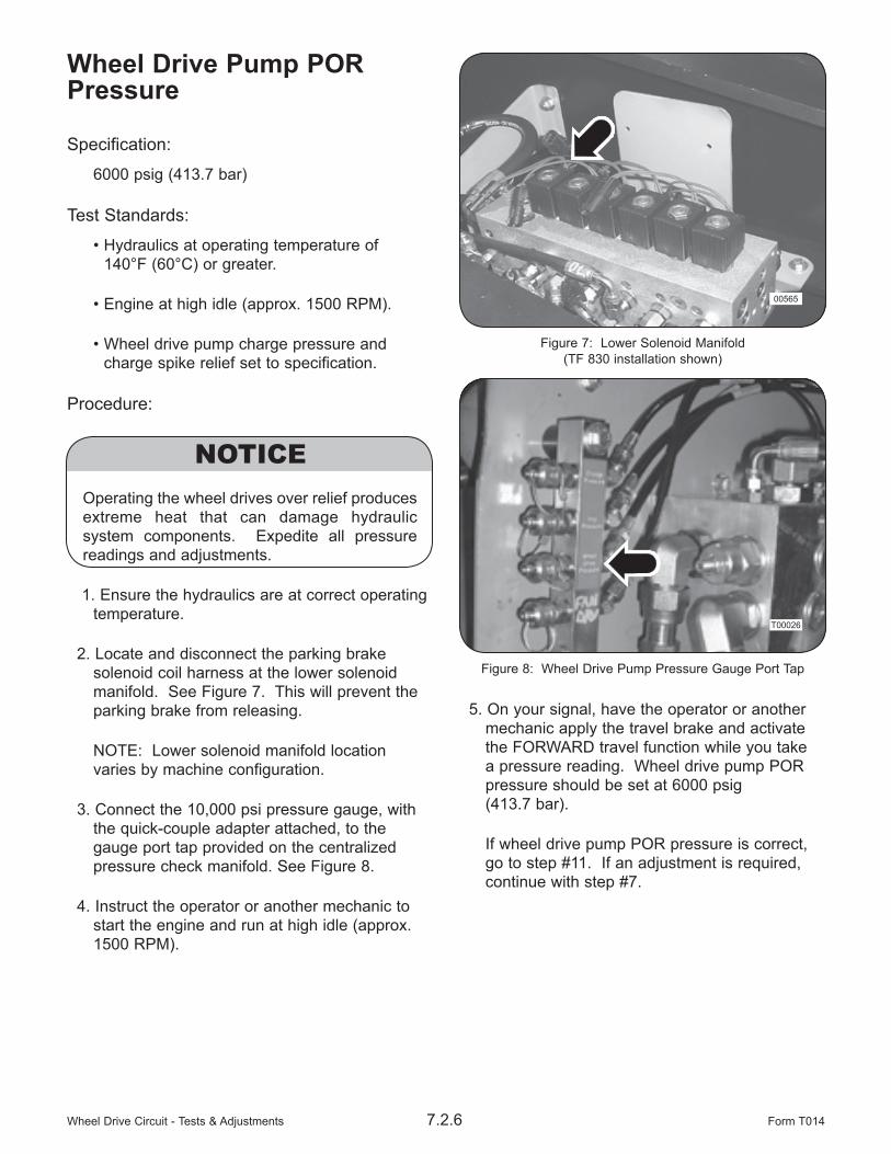
2. Locate and disconnect the parking brake solenoid coil harness at the lower solenoid manifold. See Figure 7. This will prevent the parking brake from releasing.
NOTE: Lower solenoid manifold location varies by machine configuration.
3. Connect the 10,000 psi pressure gauge, with the quick-couple adapter attached, to the gauge port tap provided on the centralized pressure check manifold. See Figure 8.
4. Instruct the operator or another mechanic to start the engine and run at high idle (approx. 1500 RPM).
5. On your signal, have the operator or another mechanic apply the travel brake and activate the FORWARD travel function while you take a pressure reading. Wheel drive pump POR pressure should be set at 6000 psig (413.7 bar).
If wheel drive pump POR pressure is correct, go to step #11. If an adjustment is required, continue with step #7.
Figure 7: Lower Solenoid Manifold (TF 830 installation shown)
00565
Figure 8: Wheel Drive Pump Pressure Gauge Port Tap
T00026

Wheel Drive Circuit - Tests & Adjustments7.2.7Form T014
6. Locate the POR relief on the wheel drive pump. See Figure 9. Use the 13mm wrench and 4mm allen wrench to loosen the jam nut on the POR relief adjustment setscrew.
7. On your signal, have the operator or another mechanic apply the travel brake and activate the FORWARD travel function while you set the POR relief to 6000 psig (41,38 Mpa).
Turning the adjustment setscrew CLOCKWISE increases the pressure setting. Turning the setscrew COUNTER-CLOCKWISE decreases the pressure setting.
8. After the correct pressure setting is made, hold the adjustment setscrew stationary and tighten the jamnut to hold the pressure setting.
9. Shut down the engine and remove the pressure gauge.
10. Re-connect the parking brake solenoid coil harness. Close and secure the swing-out pump guard.
11. If possible, start the engine and operate the wheel drives to help cool the circuit down.
12. Shut down the engine.
Figure 9: Wheel Drive POR Relief
00675

Wheel Drive Circuit - Tests & Adjustments 7.2.8 Form T014
Wheel Drive Pump Null Specification:
Obtain the lowest possible pressure between ports “X1” and “X2” with the jumper hose installed.
Test Standards:
• Hydraulics at operating temperature of 140°F (60°C) or greater.
• Engine operating at idle
Procedure:
1. Ensure the hydraulics are at correct operating temperature.
2. Locate and disconnect the parking brake solenoid coil harness at the lower solenoid manifold. See Figure 10. This will prevent the parking brake from releasing.
NOTE: Lower solenoid manifold location varies by machine configuration.
3. Access the wheel drive pump behind the swing-out guard located below the hydraulic tank.
4. Using the 3/16” allen wrench, remove the plugs from ports “X1” and “X2”. See Figure 12. Install the #6 ORBM adapters into the ports.
5. Connect the 24” (61cm) jumper hose between ports “X1” and “X2”.
6. Start the engine and run at idle. The engine will remain running throughout the procedure.
7. Connect the 10,000 psi pressure gauge, with the quick-couple adapter attached, to the gauge port tap on the wheel drive pump. See Figure 11.
Figure 11: Wheel Drive Pump Pressure Gauge Port Tap
00582
Figure 10: Lower Solenoid Manifold (TF 830 installation shown)
00565

Wheel Drive Circuit - Tests & Adjustments7.2.9Form T014
8. The mechanical null adjustment is made with a large setscrew in the control piston cover. See Figure 13. Use the 24mm wrench and 8mm allen wrench, to loosen the jamnut and turn the adjustment setscrew in and out until the gauge reads the lowest possible pressure.
NOTE: The lowest pressure reading indicates when the control piston is in the centered null position.
9. Remove the 10,000 psi gauge and install the 600 psi gauge in its place. Repeat step #8 to make the final adjustment.
10. Remove the 600 psi gauge and install the 10,000 psi gauge in its place.
The hydraulic null adjustment is made with an eccentric pin and should not be turned more than 90° from center (as indicated by a notch on the adjustment screw), otherwise damage to the eccentric pin could result.
11. The hydraulic null adjustment is made with a small setscrew on top of the stroke control. See Figure 12. Use the 13 mm wrench and 4 mm allen wrench, to loosen the jam nut and turn the adjustment setscrew in and out until the gauge reads the lowest possible pressure.
NOTE: The lowest pressure reading indicates when the control spool is in the centered null position.
12. Remove the 10,000 psi gauge and install the 600 psi gauge in its place. Repeat step #11 to make the final adjustment.
13. Shut-down engine and remove jumper hose, fittings, and gauge.
14. Re-connect the parking brake solenoid coil harness. Close and secure the rear engine guard.
15. Procedure complete.
Figure 12: Hydrostatic Pump Null Adjustments
00675
Port “X1”
Mechanical Null Adjustment Setscrew
Port “X2”
Hydraulic Null Adjustment Setscrew

Wheel Drive Circuit - Tests & Adjustments 7.2.10 Form T014
Wheel Drive Pump Case Drain PressureSpecification:
Maximum 30 psi (2 bar) allowed.
Test Standards:
• Hydraulics at operating temperature of 140°F (60°C) or greater with correct wheel drive and charge pressure settings.
• Engine operating at full throttle
Procedure:
1. Produce a gauge test hose that will allow you to connect a 60 psi gauge to the adapter that will be installed into the wheel drive pump case drain port.
2. Ensure the hydraulics are at correct operating temperature.
3. Locate and disconnect the parking brake solenoid coil harness at the lower solenoid manifold. See Figure 13. This will prevent the parking brake from releasing.
NOTE: Lower solenoid manifold location varies by machine configuration.
4. Access the wheel drive pump behind the operator’s cab in front of the hydraulic tank.
5. Locate and remove the wheel drive pump case drain plug in port “R”. Install the #12 ORBM - #4JICM adapter into the port.
6. Install the gauge test hose and pressure gauge to the case drain port adapter.
Be sure the pump case is full of oil before starting the machine otherwise catastrophic damage to the pump will occur.
7. Start engine and set the hydraulic motor shift control to the “OFF” or “High” position. See Figure 14.
8. Advance engine to full throttle.
9. On your signal, have the operator or another mechanic apply the travel brake and activate full FORWARD travel while you take a pressure reading. Then activate full REVERSE travel and take a reading.
The wheel drive pump case drain pressure should not exceed specification. If the specification is exceeded, look for conditions that would increase backpressure in the case drain circuit such as a plugged case drain filter element, failing component, etc.
10. Shutdown the engine and re-install the wheel drive pump case port plug.
11. Re-connect the parking brake solenoid coil harness.
12. Procedure complete.
Figure 14: Hydraulic Motor Shift Control
00396
Hydraulic Motor Shift “Low/Med/High”
Figure 13: Lower Solenoid Manifold (TF 830 installation shown)
00565
Wheel Drive Circuit - Tests & Adjustments7.2.11Form T014
Wheel Drive Motor Begin Of Stroke Specification:
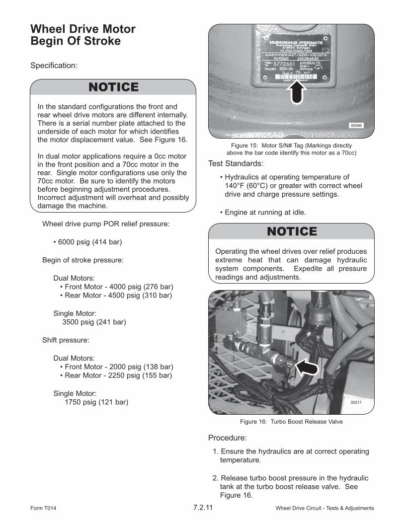
In the standard configurations the front and rear wheel drive motors are different internally. There is a serial number plate attached to the underside of each motor for which identifies the motor displacement value. See Figure 16. In dual motor applications require a 0cc motor in the front position and a 70cc motor in the rear. Single motor configurations use only the 70cc motor. Be sure to identify the motors before beginning adjustment procedures. Incorrect adjustment will overheat and possibly damage the machine.
Wheel drive pump POR relief pressure:
• 6000 psig (414 bar)
Begin of stroke pressure:
Dual Motors: • Front Motor - 4000 psig (276 bar) • Rear Motor - 4500 psig (310 bar)
Single Motor: 3500 psig (241 bar)
Shift pressure:
Dual Motors: • Front Motor - 2000 psig (138 bar) • Rear Motor - 2250 psig (155 bar)
Single Motor: 1750 psig (121 bar)
Test Standards:
• Hydraulics at operating temperature of 140°F (60°C) or greater with correct wheel drive and charge pressure settings.
• Engine at running at idle.
Operating the wheel drives over relief produces extreme heat that can damage hydraulic system components. Expedite all pressure readings and adjustments.
Procedure:
1. Ensure the hydraulics are at correct operating temperature.
2. Release turbo boost pressure in the hydraulic tank at the turbo boost release valve. See Figure 16.
Figure 15: Motor S/N# Tag (Markings directly above the bar code identify this motor as a 70cc)
00586
Figure 16: Turbo Boost Release Valve
00517
Wheel Drive Circuit - Tests & Adjustments 7.2.12 Form T014
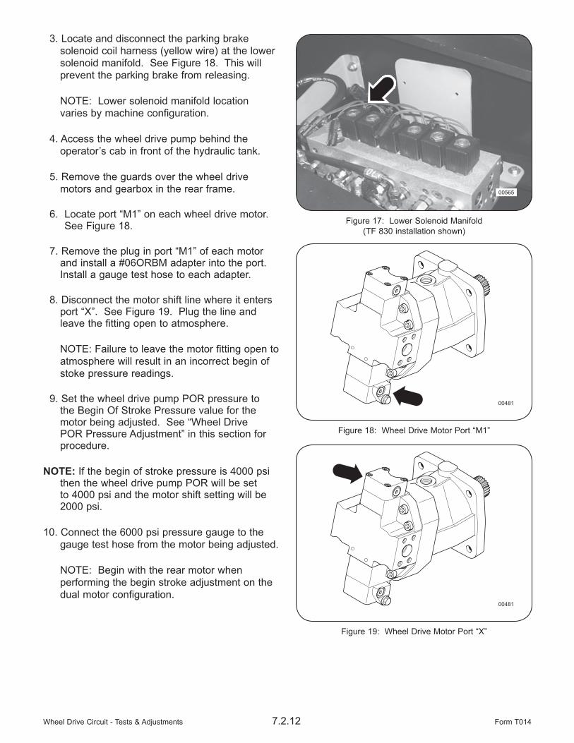
3. Locate and disconnect the parking brake solenoid coil harness (yellow wire) at the lower solenoid manifold. See Figure 18. This will prevent the parking brake from releasing.
NOTE: Lower solenoid manifold location varies by machine configuration.
4. Access the wheel drive pump behind the operator’s cab in front of the hydraulic tank.
5. Remove the guards over the wheel drive motors and gearbox in the rear frame.
6. Locate port “M1” on each wheel drive motor. See Figure 18.
7. Remove the plug in port “M1” of each motor and install a #06ORBM adapter into the port. Install a gauge test hose to each adapter.
8. Disconnect the motor shift line where it enters port “X”. See Figure 19. Plug the line and leave the fitting open to atmosphere.
NOTE: Failure to leave the motor fitting open to atmosphere will result in an incorrect begin of stoke pressure readings.
9. Set the wheel drive pump POR pressure to the Begin Of Stroke Pressure value for the motor being adjusted. See “Wheel Drive POR Pressure Adjustment” in this section for procedure.
NOTE: If the begin of stroke pressure is 4000 psi then the wheel drive pump POR will be set to 4000 psi and the motor shift setting will be 2000 psi.
10. Connect the 6000 psi pressure gauge to the gauge test hose from the motor being adjusted.
NOTE: Begin with the rear motor when performing the begin stroke adjustment on the dual motor configuration.
Figure 18: Wheel Drive Motor Port “M1”
00481
Figure 19: Wheel Drive Motor Port “X”
00481
Figure 17: Lower Solenoid Manifold (TF 830 installation shown)
00565

Wheel Drive Circuit - Tests & Adjustments7.2.13Form T014
13. Locate the begin stroke adjustment setscrew on the motor. See Figure 20. Use the 10mm wrench and 3mm allen wrench to loosen the jamnut and back the setscrew out COUNTER-CLOCKWISE a few turns. This will allow easier setting of the motor.
NOTE: The begin of stroke adjustment is made using the motor shift pressure at port “M1”. The motor shift pressure should be 1/2 the desired begin of stroke pressure.
14. On your signal, have the operator or another mechanic apply the travel brake and activate full FORWARD travel function while you turn the begin of stoke setscrew in CLOCKWISE until the shift pressure reaches specification.
15. Instruct the operator or another mechanic to deactivate the FORWARD travel function as soon as the adjustment is made to avoid excessive heat build-up in the wheel drive circuit.
16. After the correct pressure setting is made, hold the adjustment setscrew stationary and tighten the jamnut to hold the pressure setting.
17. If required, repeat step #12 thru #16 for the front wheel drive motor.
NOTE: Because the motor shift setting can be very sensitive to adjust, you may want to repeat adjustment a second time to insure proper adjustment.
18. After begin of stroke pressure have been adjusted, reset the wheel drive pump POR relief pressure to specification.
19. Shut down the engine.
20. Release turbo boost pressure at the turbo boost release valve.
21. Remove the #06ORBM adapters and gauge test hoses from the wheel drive motors. Re-install the plugs to port “M1”.
25. Re-install the guards over the wheel drive motors and transfer case.
26. Re-connect the parking brake solenoid coil harness. Close and secure the rear engine guard.
27. Procedure complete.
Figure 20: Wheel Drive Motor Begin Of Stoke Adjustment
00482
Wheel Drive Circuit - Tests & Adjustments 7.2.14 Form T014
Wheel Drive Motor Case Drain Pressure Specification:
Maximum 45 psig (3.1 bar) allowed.
Test Standards:
• Hydraulics at operating temperature of 140°F (60°C) or greater with correct wheel drive and charge pressure settings.
• Engine operating at full throttle.
Procedure:
1. Produce a gauge test hose that will allow you to connect a 60 psi gauge to the #4 adapter that will be installed into the wheel drive motor case drain port.
2. Ensure the hydraulics are at correct operating temperature.
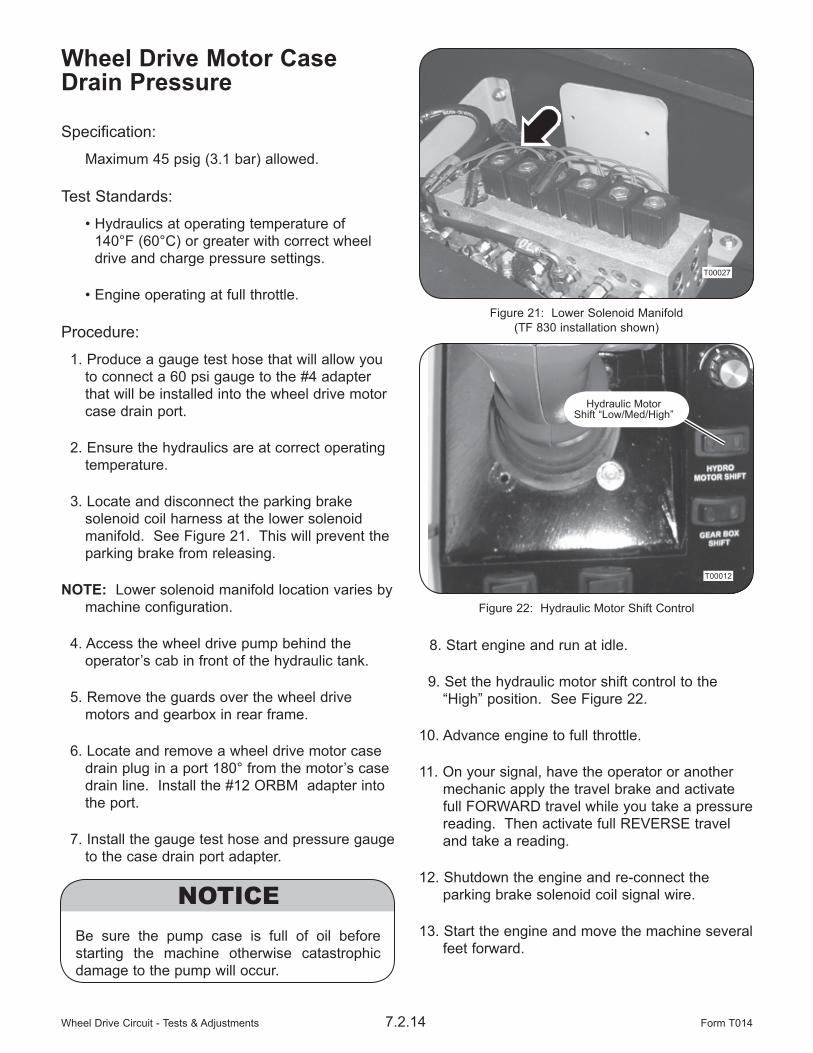
3. Locate and disconnect the parking brake solenoid coil harness at the lower solenoid manifold. See Figure 21. This will prevent the parking brake from releasing.
NOTE: Lower solenoid manifold location varies by machine configuration.
4. Access the wheel drive pump behind the operator’s cab in front of the hydraulic tank.
5. Remove the guards over the wheel drive motors and gearbox in rear frame.
6. Locate and remove a wheel drive motor case drain plug in a port 180° from the motor’s case drain line. Install the #12 ORBM adapter into the port.
7. Install the gauge test hose and pressure gauge to the case drain port adapter.
Be sure the pump case is full of oil before starting the machine otherwise catastrophic damage to the pump will occur.
8. Start engine and run at idle.
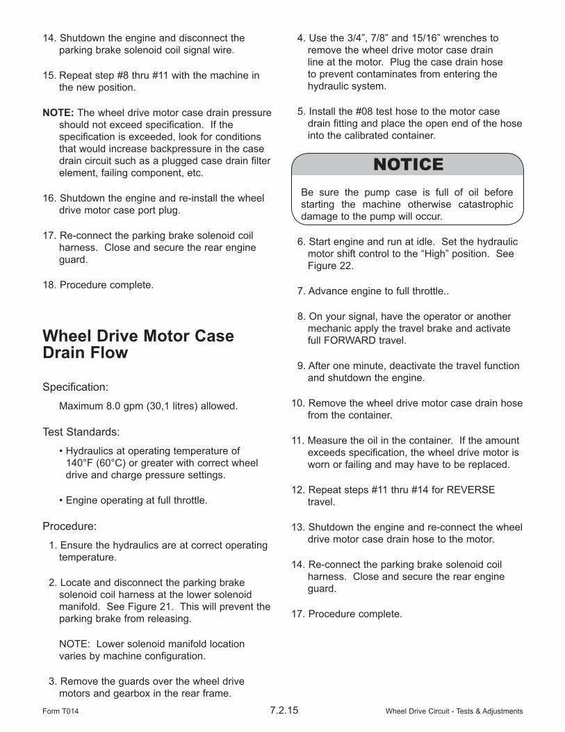
9. Set the hydraulic motor shift control to the “High” position. See Figure 22.
10. Advance engine to full throttle.
11. On your signal, have the operator or another mechanic apply the travel brake and activate full FORWARD travel while you take a pressure reading. Then activate full REVERSE travel and take a reading.
12. Shutdown the engine and re-connect the parking brake solenoid coil signal wire.
13. Start the engine and move the machine several feet forward.
Figure 21: Lower Solenoid Manifold (TF 830 installation shown)
T00027
Figure 22: Hydraulic Motor Shift Control
T00012
Hydraulic Motor Shift “Low/Med/High”
Wheel Drive Circuit - Tests & Adjustments7.2.15Form T014
14. Shutdown the engine and disconnect the parking brake solenoid coil signal wire.
15. Repeat step #8 thru #11 with the machine in the new position.
NOTE: The wheel drive motor case drain pressure should not exceed specification. If the specification is exceeded, look for conditions that would increase backpressure in the case drain circuit such as a plugged case drain filter element, failing component, etc.
16. Shutdown the engine and re-install the wheel drive motor case port plug.
17. Re-connect the parking brake solenoid coil harness. Close and secure the rear engine guard.
18. Procedure complete.
Wheel Drive Motor Case Drain Flow Specification:
Maximum 8.0 gpm (30,1 litres) allowed.
Test Standards:
• Hydraulics at operating temperature of 140°F (60°C) or greater with correct wheel drive and charge pressure settings.
• Engine operating at full throttle.
Procedure:
1. Ensure the hydraulics are at correct operating temperature.
2. Locate and disconnect the parking brake solenoid coil harness at the lower solenoid manifold. See Figure 21. This will prevent the parking brake from releasing.
NOTE: Lower solenoid manifold location varies by machine configuration.
3. Remove the guards over the wheel drive motors and gearbox in the rear frame.
4. Use the 3/4”, 7/8” and 15/16” wrenches to remove the wheel drive motor case drain line at the motor. Plug the case drain hose to prevent contaminates from entering the hydraulic system.
5. Install the #08 test hose to the motor case drain fitting and place the open end of the hose into the calibrated container.
Be sure the pump case is full of oil before starting the machine otherwise catastrophic damage to the pump will occur.
6. Start engine and run at idle. Set the hydraulic motor shift control to the “High” position. See Figure 22.
7. Advance engine to full throttle..
8. On your signal, have the operator or another mechanic apply the travel brake and activate full FORWARD travel.
9. After one minute, deactivate the travel function and shutdown the engine.
10. Remove the wheel drive motor case drain hose from the container.
11. Measure the oil in the container. If the amount exceeds specification, the wheel drive motor is worn or failing and may have to be replaced.
12. Repeat steps #11 thru #14 for REVERSE travel.
13. Shutdown the engine and re-connect the wheel drive motor case drain hose to the motor.
14. Re-connect the parking brake solenoid coil harness. Close and secure the rear engine guard.
17. Procedure complete.

Wheel Drive Circuit - Tests & Adjustments 7.2.16 Form T014
THIS PAGE LEFT BLANK FOR NOTES