section 6: parts section - jackson wws€¦ · part number 04730-209-07-37. o-ring 05330-011-74-55...
TRANSCRIPT

AJ-54C Series Technical Manual 7610-002-30-91 Issued: 03-22-2006 Revised: N/A
SECTION 6: PARTS SECTION
94
PREWASH & WASH PUMP WELDMENTS
Intake Suction Scoop Weldment05700-021-87-60
Prewash IntakeStrainer Weldment05700-021-74-96
Prewash StrainerBracket
05700-021-74-94
Prewash Pump WeldmentAJ-76/AJ-90 Right to Left models:
05700-002-11-96
Wash PumpWeldment
05700-041-68-88
Prewash Pump WeldmentAJ-76/AJ-90 Left to Right models:
05700-002-10-62
Prewash Pump WeldmentAJ-76CGP Left to Right model
05700-002-43-56
Scoop, Intake Suction WashWeldment
05700-002-51-20
Pump DischargeWeldment
05700-002-50-90
Gasket05330-002-54-55
Wash Pump Weldment05700-002-50-92
Prewash Pump WeldmentAJ-76CGP Right to Left model
05700-002-42-69

AJ-54C Series Technical Manual 7610-002-30-91 Issued: 03-22-2006 Revised: N/A
SECTION 6: PARTS SECTION
95
PREWASH ARM/UPPER WASH ARM ASSEMBLY
Lanyard05340-011-72-46
End Cap Replacement Kit06401-003-10-19
Upper Wash Arm Manifold Weldment05700-031-75-07
Cap, Wash Tube05700-021-69-68
Service Note:When replacing the 10-32 screws in the End Caps, itis recommended that a thread locking fluid be used toensure that the screws do not back out during normaloperation.
Replacement Kit Note:The replacement kit for the end capincludes the endcap, lanyard, mountingscrew and the locknut.
Upper Wash Manifold Support Bracket05700-021-73-97
End CapReplacement Kit06401-003-10-19
Replacement Kit Note:The replacement kit for the end capincludes the endcap, lanyard, mountingscrew and the locknut.
Prewash TubeWeldment
05700-001-16-89
Complete Prewash Arm Assembly05700-021-74-65
Complete Upper Arm Assembly05700-031-75-33

AJ-54C Series Technical Manual 7610-002-30-91 Issued: 03-22-2006 Revised: N/A
SECTION 6: PARTS SECTIONLOWER WASH ARM ASSEMBLY
96
Screw, 10-32 x 3/8” Truss Head05305-173-12-00
Complete Lower Wash Arm Assembly05700-031-75-32
End Cap Replacement Kit06401-003-10-19
Lanyard6 per
5340-011-72-46
Locknut, 10-24 with Nylon Insert05310-373-01-00
Lower Wash Arm Manifold Weldment 05700-031-75-06
Manifold Quick-Release Key05700-011-94-45
SERVICE NOTE: When replacing the 10-32 screws in the End Caps, it is recommended that a thread locking fluid be used toensure that the screws do not back out during normal operation.
Lower Wash Arm Support Bracket05700-011-71-20
Secured with Locknut, 1/4”-20 with Nylon Insert05310-374-01-00
Replacement Kit Note:The replacement kit for the end cap includes the end-cap, lanyard, mounting screw and the locknut.

AJ-54C Series Technical Manual 7610-002-30-91 Issued: 03-22-2006 Revised: N/A
SECTION 6: PARTS SECTION
97
CURTAINS/TUB MAGNETS
Curtain, 21” Long x 20-1/2” Wide08415-131-73-45
Curtain, 12” Long x 20-1/2” Wide08415-131-73-44
Curtain Rod05700-021-73-43
Long Curtain Decal09905-011-73-84
Short Curtain Decal09905-011-73-82
Curtain, 24 1/2” Long x 20-1/2” WideCGP MODELS ONLY
08415-002-47-37
Extra Long Curtain DecalCGP MODELS ONLY
09905-002-52-69Middle Curtain Hook
05700-011-72-65
Curtain Hook05700-011-83-54
Limit Switch Bracket05700-021-71-18
Conveyor Switch Replacement Kit06401-003-11-79
Replacement Kit Note:The conveyor switch replacement kitcomes with the switch, a terminal anda wire nut.
Service Note:The cord for the conveyor switch needs to be cut to length in the fieldand have the pink terminal applied there.

AJ-54C Series Technical Manual 7610-002-30-91 Issued: 03-22-2006 Revised: N/A
SECTION 6: PARTS SECTION
98
FINAL RINSE ASSEMBLY
Final Rinse Manifold Weldment05700-021-74-88
Upper Rinse Arm Replacement Kit06401-003-10-08
Lower Rinse Arm Replacement Kit06401-003-10-09
Rinse Pan Strainer Weldment05700-041-85-09
Rinse Drain Control Plate05700-011-68-70
Rinse Drain Control Plate05700-011-68-70
Rinse Drain Overflow Plate05700-002-53-62
Left Rinse Pan Locator Bracket05700-021-92-38
Right Rinse Pan Locator Bracket05700-021-92-37
Rinse Tray Weldment(All models except CGP)
05700-031-66-75
Rinse Tray Weldment(CGP models only)
05700-031-66-75
Optional Parts for CGPModels
Locknut, 1/4”-20 with Nylon Insert05310-374-01-00
End plugs can be ordered usingpart number 04730-209-07-37.
O-Ring 05330-011-74-55
Retaining Ring (Not Shown)05340-112-01-11
Gasket 05330-111-42-81
Rinse ArmSupport Bracket05700-011-71-19
Replacement Kit Note:The replacement kits for the rinsearms have the rinse arms, end caps, o-rings and the retaining rings.

AJ-54C Series Technical Manual 7610-002-30-91 Issued: 03-22-2006 Revised: N/A
SECTION 6: PARTS SECTIONDRIVE ASSEMBLY
99
1
2
3
4
11
12
13
18
17
14
15
16
5
6
7
8
9
10
See Detail A

AJ-54C Series Technical Manual 7610-002-30-91 Issued: 03-22-2006 Revised: N/A
SECTION 6: PARTS SECTION
100
DRIVE ASSEMBLY (CONTINUED)
ITEM QTY DESCRIPTION Mfg. No.1 1 Drive Plate and Rod Weldment 05700-021-67-44
Replacement Kit with Expansion Legs 06401-021-86-80Replacement Kit with Expansion Legs/Adjuster Crank 06401-011-94-54
2 1 Adjuster Crank Assembly 05700-021-69-953 1 Skotch Yoke Weldment Replacement Kit 06401-003-08-484 2 Coupling & Expansion Leg Weldment 05700-021-67-505 1 Pawl Bar Drive Linkage Casting 09515-021-87-736 1 Spacer Plate 05700-011-67-587 2 Pillow Block Replacement Kit 06401-003-08-508 2 Shaft Collar 05700-011-89-189 1 Drive Socket 05700-021-67-3910 1 Drive Plate 05700-021-67-4211 2 Pillow Block 03120-021-71-8712 1 Drive Spring 05315-011-83-5113 2 Shaft Collar 05700-011-89-1814 1 Drive Motor Mounting Bracket 05700-031-73-5615 1 Adjuster Spring 05315-011-71-9016 1 Adjusting Handle Weldment 05700-021-72-2817 1 Drive Motor Replacement Kits
Drive Motor (50 Hz Models) 06401-003-08-411 Drive Motor (208-230 Volt, 60 Hz, Single Phase Models) 06401-003-08-42
Drive Motor (208-230 Volt, 60 Hz, Three Phase Models) 06401-003-08-40Drive Motor (600 Volt, 60 Hz, Three Phase Models) 06401-003-08-43
18 1 Gear Drive 06105-011-87-2019 1 Roller Bearing 03120-011-71-8120 1 Drive Hub 05700-011-67-97
19 20
Detail A
Front Drive Motor CoverReplacement Kit06401-003-11-64
Rear Drive Motor CoverReplacement Kit06401-003-10-18
Replacement Kits Notes:The replacement kits for the drive motor covers comewith the weldments and the mounting hardware.

AJ-54C Series Technical Manual 7610-002-30-91 Issued: 03-22-2006 Revised: N/A
SECTION 6: PARTS SECTIONLUBRICATION CHART FOR DRIVE GEAR
101
Note: The maintenance procedures detailed here are manufacturer’s instructions for the WINSMITH brand of gear reducerthat is installed on the rack conveyors covered in this manual.
Ambient Temperature -30 - 15°F 16 - 50°F 51 - 95°F 51 - 95°F 96 - 131°F 96 - 131°FFinal Stage Worm Speed1 up to 2000 FPM up to 2000 FPM up to 450 FPM above 450 FPM up to 450 FPM above 450 FPMISO Viscosity Grade 220 460 680 460 680 4601
AGMA Lubricant No. 5S #7 Compounded #8 Compounded #7 Compounded 8S 7S
Mobil SHC 630 600W Super Extra Hecla Super 600W Super SHC 636 SHC 634Cylinder Cylinder
American Lubricants SHC-90W AGMA #7 Gear Oil AGMA #8 Gear Oil AGMA #7 Gear Oil N/A N/A
Castrol Tribol 800/220 Tribol 1105-7C Tribol 1105-8C Tribol 1105-7C Tribol 800/680 Tribol 800/460
Chevron Tegra 220 Cylinder Oil W460 Cylinder Oil W680 Cylinder Oil W460 Tegra 680 Tegra 460
Conoco Syncon R & O Inca Oil 460 Inca Oil 680 Inca Oil 460 N/A Syncon R & O220 460
Exxon (Esso) Teresstic SHP220 Spartan EP 460 Spartan EP 680 Spartan EP 460 Teresstic SHP 680 Teresstic SHP460
Fiske Brothers SPO-MG SPO-277 SPO-288 SPO-277 N/A N/A
Shell Omala RL 220 Valvata J 460 Valvata J 680 Valvata J 460 Omala RL 680 Omala RL 460
Texaco Pinnacle 220 Vanguard 460 Vanguard 680 Vanguard 460 Pinnacle 680 Pinnacle 460
(1) The sliding velocity in feet per minute (FPM) for standard ratios is determined by multiplying the speed of the worm in RPM bythe factor from the table below. For selecting proper lubricant, use the speed of the worm in the final stage (input RPM divided bythe first stage ratio).

AJ-54C Series Technical Manual 7610-002-30-91 Issued: 03-22-2006 Revised: N/A
SECTION 6: PARTS SECTION
102
DOOR ASSEMBLIES
ITEM QTY DESCRIPTION Mfg. No.1 1 Wash Door Weldment 05700-003-13-352 1 Prewash Door Weldment
Left to Right Model 05700-003-13-42Right to Left Model 05700-003-13-40
3 1 Screw, 8-32 x 1/4” Long 05305-172-09-004 1 Door Switch Magnet 05700-111-51-685 1 Door Guide 05700-111-70-926 1 Door Stop Weldment, Right 05700-002-96-337 1 Door Stop Weldment, Left 05700-002-96-328 2 Locknut, 10-24 SS Hex with Nylon Insert 05310-373-01-009 2 Door Stop Weldment, Prewash 05700-002-05-46
Wash Door Handle Weldment05700-011-82-63
Prewash Door Handle Weldment05700-011-80-45
Wash Door Hood Support: 05700-031-84-1322” Prewash Door Hood Support: 05700-031-84-14
Door Stiffener (Not Shown) 05700-031-83-43
Door Catch Weldment05700-031-84-80
2
Locknut, 1/4”-20 with Nylon Insert05310-374-01-00
1
57 8 86
34
Left Door Guide Weldment 05700-002-32-51
Right Door Guide Weldment 05700-031-76-44

AJ-54C Series Technical Manual 7610-002-30-91 Issued: 03-22-2006 Revised: N/A
SECTION 6: PARTS SECTION
103
PAWL BAR MISCELLANEOUS COMPONENTS
Pawl Bar Gutter Weldment Replacement Kit06401-003-09-95
Bottom Guide Block
Top Guide Block
Pawl Bar Gutter Gasket05330-011-68-55
Replacement Kits Notes:The pawl bar gutter weldmentreplacement kit contains the weld-ment, a gasket and the mountinghardware. The guide block kit con-tains both blocks and a gasket.
Service Note: It is highly recommended that whenchanging out one guide block, that the other be changedout as well, along with the gasket.
Guide Block Replacement Kit06401-003-10-15
Pawl Bar Roller Replacement Kit06401-003-11-80
Replacement Kit Notes:The replacement kit for the pawl bar roller comes with the roller, rollershaft, hardware and locknut as shown.
Pawl Bar Bracket (with studs) Weldment05700-031-84-68Pawl Bar Bracket (without tabs) Weldment
05700-031-92-36

AJ-54C Series Technical Manual 7610-002-30-91 Issued: 03-22-2006 Revised: N/A
SECTION 6: PARTS SECTIONAJ-54 PAWL BAR ASSEMBLY
104
Pawl Bar Dog Casting12 per
05700-021-69-00
Pawl Bar Spacer24 per
05700-011-71-45
Pawl Bar Weldment05700-031-75-09
AJ-54 Complete Assembly with Hardware06401-131-81-01
AJ-54 Prison Assembly with Hardware06401-231-81-01

AJ-54C Series Technical Manual 7610-002-30-91 Issued: 03-22-2006 Revised: N/A
SECTION 6: PARTS SECTIONAJ-76 PAWL BAR ASSEMBLIES
105
Left to Right Assembly
Pawl Bar Weldment05700-031-75-18
Pawl Bar Spacer05700-011-71-45
Pawl Bar Dog Casting05700-021-69-00
Pawl Bar Weldment05700-031-82-00
Right to Left Assembly
AJ-76 Complete L-R Assembly06401-141-81-04
AJ-76 Complete R-L Assembly06401-241-81-04
AJ-76 Prison Assembly06401-341-81-04

AJ-54C Series Technical Manual 7610-002-30-91 Issued: 03-22-2006 Revised: N/A
SECTION 6: PARTS SECTIONAJ-90 PAWL BAR ASSEMBLIES
106
Left to Right Assembly
Bolt, 3/8”-16 x 1-3/4” Long5306-011-36-94
Locknut, 3/8”-16 with Nylon Insert05700-011-72-55
Pawl Bar Spacer05700-011-71-45
Pawl Bar Dog Casting05700-021-69-00
Pawl Bar Weldment05700-031-74-19
Right to Left Assembly
All associated hardware, spacers and castings may beordered using the part numbers indicated in the aboveassembly.
Pawl Bar Weldment05700-041-82-01
Both assemblies contain 20 pawl bar dog castings. Pleasenote the direction of installation as indicated on the abovedrawings. When replacing pawl bar dog castings, ensure tore-install in the appropriate direction. If you do not, then therack will not be pulled through the machine during operation.
AJ-90 Complete L-R Assembly06401-141-81-05
AJ-90 Complete R-L Assembly06401-241-81-05
AJ-90 Prison Assembly06401-341-81-05

AJ-54C Series Technical Manual 7610-002-30-91 Issued: 03-22-2006 Revised: N/A
SECTION 6: PARTS SECTIONAJ-54 RACK RAIL ASSEMBLY
107
Spacer6 per
05700-011-71-44
Limit Switch Actuator Assembly1 per
05700-021-77-03
Actuator Switch Replacement Kit06401-003-10-14
Rack Rail Weldment05700-031-81-95
Opposite Rack Rail 05700-041-75-29
Replacement Kit Note:The replacement kit for the actuatorswitch comes with the switch, two spac-ers and the mounting hardware.

AJ-54C Series Technical Manual 7610-002-30-91 Issued: 03-22-2006 Revised: N/A
SECTION 6: PARTS SECTIONAJ-76 RACK RAIL ASSEMBLIES
108
Rack Guide Weldment05700-031-75-53
Actuator SwitchReplacement Kit06401-003-10-99
Actuator Switch Replacement Kit06401-003-10-14
Actuator Assembly05700-002-91-11
Spacer6 per
05700-011-71-44
Left to Right Assembly
Rack Guide Weldment05700-041-75-47
Opposite Rack Rail 05700-041-75-46
Actuator Switch Replacement Kit06401-003-10-86
Actuator Switch Replacement Kit06401-003-10-14
Actuator Assembly05700-021-77-03
Spacer6 per05700-011-71-44
Right to Left Assembly
Opposite Rack Rail 05700-041-75-46
Replacement Kit Notes:The replacement kits for the actuatorswitches come with the switch, two spacersand the mounting hardware.

AJ-54C Series Technical Manual 7610-002-30-91 Issued: 03-22-2006 Revised: N/A
SECTION 6: PARTS SECTIONAJ-90 RACK RAIL ASSEMBLIES
109
Rack Guide Weldment05700-031-81-55
Opposite Rail05700-041-75-99
Actuator Switch Replacement Kit06401-003-10-14
Limit Switch Actuator Assembly05700-002-91-11
Left to Right Assembly
Actuator Switch ReplacementKit
Rack Guide Spacer05700-011-71-44
Right to Left Assembly
Limit Switch Actuator Assembly05700-021-77-03
Rack Guide Spacer05700-011-71-44
Actuator Switch Replacement Kit06401-003-10-85
Actuator Switch Replacement Kit06401-003-10-14
Rack Guide Weldment 05700-031-81-56
Opposite Rail05700-041-75-98
Replacement Kit Notes:The replacement kits for the actu-ator switches come with theswitch, two spacers and themounting hardware.

AJ-54C Series Technical Manual 7610-002-30-91 Issued: 03-22-2006 Revised: N/A
SECTION 6: PARTS SECTION
110
MISCELLANEOUS PARTS AND WELDMENTS
Run Off Sheet Weldment05700-021-71-39
Plate, Right WaterDirectional
05700-021-79-23
Plate, Left WaterDirectional
05700-021-79-27 Splash Shield Weldment05700-031-85-16
Hole Direction Plate Replacement Kit06401-003-10-00
Replacement Kit Note:The kit for the hole direction plate comeswith the plate, a new gasket and themounting hardware.
Pipe Clamp05700-000-35-05
Rinse Drain Plate ReplacementKit
(CGP Models Only)06401-003-10-07
Rinse Drain Plug Replacement Kit06401-003-10-06
Rinse Drain Weldment Replacement Kit 06401-003-10-05
Rinse Drain Plate Gasket05330-011-72-27
Replacement Kits Notes:The kits for the drain weldments anddrain plugs come with theweldments/parts, a new gasket and themounting hardware.

AJ-54C Series Technical Manual 7610-002-30-91 Issued: 03-22-2006 Revised: N/A
SECTION 6: PARTS SECTION
111
MANIFOLDS/STRAINER SUPPORT WELDMENTS
Prewash Manifold WeldmentAJ-66 Models Only05700-031-69-70
Prewash Manifold WeldmentAJ-80 Models Only05700-002-24-94
Prewash Manifold Weldment(CGP Models Only)05700-002-59-51
Wash Manifold Weldment05700-031-71-13
Wash Manifold Weldment(CGP Models Only)
05700-002-51-14
Shoulder Bolt Wingnut Weldment05700-002-46-02
Wash Fill Tube Weldment05700-021-71-21
Prewash Fill Tube Weldment(AJ-66 & AJ-80 Models Only)
05700-021-74-76
Vellumoid Gasket05330-111-42-81
Wash Strainer Separator Weldment05700-031-84-38

AJ-54C Series Technical Manual 7610-002-30-91 Issued: 03-22-2006 Revised: N/A
SECTION 6: PARTS SECTION
112
STRAINERS
Back Strainer Weldment05700-021-85-11
Drain Guard Strainer Weldment05700-002-09-15
Front Strainer Weldment05700-021-85-10
Screen Strainer with Handle Weldment
05700-002-09-04
Overflow Strainer Support05700-001-96-48
Tub Strainer Weldment (CGP Models)05700-002-03-21
Wash Intake Strainer Weldment (CGP Models)05700-002-51-52
AJ-54C Series Technical Manual 7610-002-30-91 Issued: 03-22-2006 Revised: N/A
SECTION 6: PARTS SECTION
113
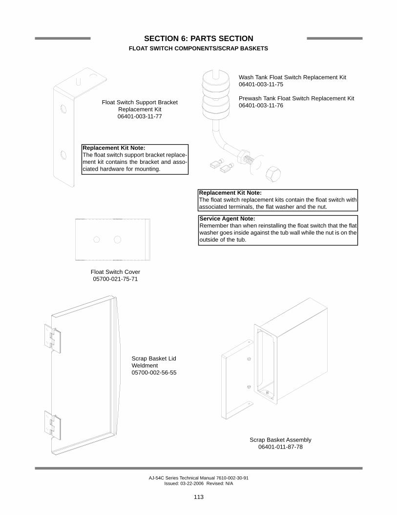
FLOAT SWITCH COMPONENTS/SCRAP BASKETS
Float Switch Support BracketReplacement Kit06401-003-11-77
Float Switch Cover05700-021-75-71
Scrap Basket LidWeldment05700-002-56-55
Scrap Basket Assembly06401-011-87-78
Wash Tank Float Switch Replacement Kit06401-003-11-75
Prewash Tank Float Switch Replacement Kit06401-003-11-76
Replacement Kit Note:The float switch replacement kits contain the float switch withassociated terminals, the flat washer and the nut.
Service Agent Note:Remember than when reinstalling the float switch that the flatwasher goes inside against the tub wall while the nut is on theoutside of the tub.
Replacement Kit Note:The float switch support bracket replace-ment kit contains the bracket and asso-ciated hardware for mounting.

AJ-54C Series Technical Manual 7610-002-30-91 Issued: 03-22-2006 Revised: N/A
SECTION 6: PARTS SECTION
114
VENT COWL ASSEMBLY/VENT SCOOP OPTION
Vent Cowl Cover Replacement Kit06401-003-10-16
Gasket, Top Vent Cowl 05330-031-83-47
Vent Cowl Replacement Kit06401-003-11-62
Gasket, Side Vent Cowl05330-031-83-48
VENT SCOOP OPTION
Replacement Kit Note:The kit for the vent cowl comes with the ventcowl weldment, new gaskets and the lock-nuts needed to mount it.
Vent Scoop Assembly05700-002-04-08

AJ-54C Series Technical Manual 7610-002-30-91 Issued: 03-22-2006 Revised: 04-19-2007
SECTION 6: PARTS SECTION
115
EXHAUST FAN CONTROL/TABLE LIMIT SWITCH OPTIONS
Delay Timer05945-011-65-44
2” Din Rail05700-002-36-09
Kit, Exhaust Fan - Electric & Steam Models05700-031-90-53
Kit, Exhaust Fan - Gas Models05700-003-14-59
Terminal Board05940-011-84-41
Whisker Switch Assembly05700-002-23-94
Whisker Limit Switch & Lever05930-303-40-01
Whisker Limit SwitchMounting Bracket05700-000-14-55
Limit Switch05930-002-62-81
Striker Plate Limit SwitchAssembly
05700-002-62-94
Proximity LimitSwitch Sensor
06685-002-94-15
Bracket, Proximity Switch05700-002-94-93
Photoelectric Limit SwitchAssembly
05700-002-93-81
FAN LOAD ON TIMER OUTPUT5A, 1/4HP, 240 V AC MAX
Decal, Fan Load09905-003-32-20

AJ-54C Series Technical Manual 7610-002-30-91 Issued: 03-22-2006 Revised: N/A
SECTION 6: PARTS SECTION
116
SIDE LOADER TRACK ASSEMBLY/LEG REPLACEMENTS/STRAINER
ITEM QTY DESCRIPTION Mfg. No.1 1 Track Weldment (Left to Right) 24” 05700-031-78-98
1 Track Weldment (Right to Left) 24” 05700-031-95-201 Track Weldment (Left to Right) 30” 05700-003-04-571 Track Weldment (Right to Left) 30” 05700-003-04-58
2 1 Actuator Switch Replacement Kit 06401-003-10-643 2 Spacer 05700-011-71-444 1 Leg Socket Replacement Kit 06401-003-09-795 1 Leg Support Replacement Kit 06401-003-09-806 1 Bullet Foot 05340-108-01-03
1
2
3
Side loader track assembly(left to right model shown).
Replacement Kits Notes:The actuator switch replacement kit comes with theactuator weldment, mounting hardware and (2)spacers.
The leg socket replacement kit has the leg socket,mounting hardware and set screw.
The leg support replacement kit has the leg and thebullet foot included.
4
5
6
Front Strainer Weldment05700-021-85-10

AJ-54C Series Technical Manual 7610-002-30-91 Issued: 03-22-2006 Revised: N/A
SECTION 6: PARTS SECTION
117
SIDE LOADER PAWL BAR ASSEMBLIES/PAWL BAR BRACKET/MAGNET
Pawl Dog Wing Weldment05700-021-86-79
Pawl Bar Spacer05700-011-71-45
Drive Linkage Replacement Kit (L-R)06401-003-11-59
Drive Linkage Replacement (R-L)06401-003-11-60
Kit, Pawl Bar Replacement: 06401-131-86-90Kit, 30” Pawl Bar Replacement: 06401-231-86-90
Replacement Kit Note:The kits for the pawl bars come with the barweldment, (3) dogs and the hardware.
Replacement Kit Note:The replacement kits for the drive linkages come alsowith the hardware for mounting them to the pawl bars.
Pawl Bar Roller Bracket05700-031-77-94
Replacement Kit Note:The conveyor switch replacementkit comes with the switch, a termi-nal and a wire nut.
Service Note:The cord for the conveyor switch needs tobe cut to length in the field and have thepink terminal applied there.
See page entitled “Pawl BarMiscellaneous Components”for other parts used on theSide Loader.

AJ-54C Series Technical Manual 7610-002-30-91 Issued: 03-22-2006 Revised: N/A
SECTION 6: PARTS SECTION
118
SIDE LOADER VENT COWL OPTION
VENT SCOOP OPTIONVent Scoop Assembly
05700-002-04-08
STANDARD ASSEMBLY
Vent Cowl Cover Replacement Kit06401-003-10-16
Vent Cowl Replacement Kit (Left to Right)06401-003-11-81
Vent Cowl Replacement Kit (Right to Left)06401-003-11-83
Replacement Kit Note:The replacement kit(s) for the vent cowls come with thecowls, the gaskets and mounting hardware.
Replacement Kit Note:The cover kit contains thecover and the hardware formounting it.
Vent Cowl Gasket, Top: 05330-031-83-47Vent Cowl Gasket, Side: 05330-031-83-48
Service Note:One of the sidegaskets that comein the kit will needto be cut to lengthin order to fit prop-erly on the unitwhen replaced.
Vent Cowl Assembly for Hooded Side Loader Option
05700-003-15-66

AJ-54C Series Technical Manual 7610-002-30-91 Issued: 03-22-2006 Revised: N/A
SECTION 6: PARTS SECTIOND226 STEAM BOOSTER CONTROL BOX ASSEMBLY
119
10
Decal, Warning, Disconnect Power09905-100-75-93
Decal, Schematic, D226 Booster (on theinside of the control box cover)
09905-002-78-56
Cover, Control Box05700-001-19-82
Decal, L1-L209905-002-78-67
Ground Lug05940-200-76-00
Spacer, Terminal Block05700-011-40-05
Decal, Ground09905-011-86-86
Thermostat06680-500-01-77
Conduit Fitting, .231” x.394”05975-011-49-03
Terminal Block05940-500-09-61
Control Box with Decal06401-002-78-87
Decal Only09905-021-44-97
Light, Red05945-111-21-57
Power Switch05930-011-49-55

AJ-54C Series Technical Manual 7610-002-30-91 Issued: 03-22-2006 Revised: N/A
SECTION 6: PARTS SECTIOND226 STEAM BOOSTER PLUMBING ASSEMBLY
120
17 2
12 3 45 68
9
10
11
12
13
1415
16
17
18
19
20
21 22
23
24
25
26 27 28
29
31 31
7
32
3330

AJ-54C Series Technical Manual 7610-002-30-91 Issued: 03-22-2006 Revised: N/A
SECTION 6: PARTS SECTIOND226 STEAM BOOSTER PLUMBING ASSEMBLY (CONTINUED)
121
ITEM QTY DESCRIPTION Mfg. No.1 1 Water Pressure Regulator, 3/4” 04820-100-01-062 2 Nipple, Brass, 3/4” NPT x 6” Long 05700-001-26-743 2 U-Bolt, 6”, 5/8”-11 Thread 5306-458-01-044 1 Platform Weldment 05700-002-78-025 1 Heat Exchanger 4420-100-01-056 1 Steam Trap, 3/4” 06680-500-02-777 1 Bushing, 2” NPT x 3/4” NPT, Black Iron 04730-902-06-348 2 Elbow, 3/4” NPT, Brass 04730-206-13-009 6 Nipple, 1” NPT, Close, Black Iron 04730-907-08-3410 2 Union, 3/4” NPT, Brass 04730-212-05-0011 2 Bushing, 2” NPT x 3/4” NPT, Brass 04730-202-18-0012 4 Nipple, 3/4” NPT x 1-3/8” Long 04730-207-34-0013 1 Bushing, Hex 3/4” M x 1/2” F, Brass 04730-002-56-2714 1 Y-Strainer, 1” NPT, Black Iron 04730-217-02-3215 2 Pressure Gauge 06685-111-88-3416 1 Steam Relief Valve 04820-100-07-0617 2 Nipple, 3/4” NPT x 4” Long, Brass 04730-207-05-0018 2 Tee, 3/4” NPT x 3/4” NPT x 3/4” NPT, Brass 04730-211-01-3419 1 Bushing, 2” NPT x 1” NPT, Black Iron 04730-002-94-5120 3 Elbow, 90°, 1” NPT, Black Iron 04730-906-03-3421 2 Nipple, 1” NPT x 4” Long, Black Iron 04730-907-09-3422 1 Elbow, 90°, Street, 3/4” NPT, Black Iron 04730-011-87-3723 1 Nipple, Pigtail, 1/4” NPT 04730-907-14-3424 1 Coupling, 1/4” NPT x 1/4” NPT 04730-904-01-3425 1 Steam Solenoid Valve, 240VA 04820-100-29-3425 1 Steam Solenoid Valve, 200VA 04820-002-93-6625 1 Steam Solenoid Valve (ASCO) 04820-002-90-2626 1 Tee, 3/4” NPT x 3/4” NPT x 1/4” NPT, Brass 04730-211-04-0027 1 Valve, Test Cock, 1/4” NPT 04810-011-72-6728 1 Tee, 1” NPT x 1” NPT x 1” NPT, Black Iron 04730-911-01-3429 1 Valve, Safety Relief 1” NPT 04820-100-01-3530 1 Tee, 1” NPT x 1” NPT x 1/4” NPT, Black Iron 04730-911-01-0031 2 Union, 3/4” NPT, Black Iron 04730-912-01-0032 2 Nipple, 3/4” NPT x 2” Long, Brass 04730-207-46-0033 2 Nipple, 3/4” NPT, Close, Black Iron 04730-907-01-00

AJ-54C Series Technical Manual 7610-002-30-91 Issued: 03-22-2006 Revised: N/A
SECTION 6: PARTS SECTIONGO*BOX COMPONENTS
122
A GO*BOX is a kit of the most needed parts for a particular model or model family to successfully effect a repair in the firstcall 90% or more of the time.
The following components may be ordered together using part number 06401-002-14-98.
QTY DESCRIPTION Mfg. No.1 Drive Motor Contactor 05945-111-68-381 Contactor, Wash Heater, 3 ph, 3 pole 05945-002-24-701 Contactor, Wash Heater, 1 ph, 4 pole 05945-111-68-372 Final Rinse Arm End Cap 05700-011-35-921 Float Switch, Dual, Wash & Prewash 06680-121-70-711 Gasket, Pawl Bar Gutter 05330-011-68-551 Gauge, Pressure 06685-111-88-346 Glide, Door Edge 05700-111-70-922 Magnet, Door Reed Switch 05930-111-51-682 O Ring, Prewash Manifold 05330-400-12-082 O Ring, Wash Manifold 05330-011-74-561 Overload, Drive Motor 05945-111-68-391 Overload, Wash Motor 05945-111-68-401 Relay,120v, 3 PDT 05945-111-72-511 Relay,120v,50/60Hz 3A Control 05945-111-35-191 Repair Kit, 3/4" Vacuum Breaker 04820-001-60-574 Roller, Pawl Bar 05700-011-68-161 Seal Kit for Wash and Prewash pump 05330-011-71-982 Solenoid Valve, Fill & Rinse 04810-100-53-002 Switch, Power 05930-011-49-552 Switch, Reed, Actuator (NC) 05930-111-68-441 Switch, Reed, Door (NO) 05930-111-68-861 Thermometer, 48" Capillary 06685-111-68-481 Thermometer, 96" Capillary 06685-111-68-492 Thermostat, Wash High Limit 05930-121-71-362 Thermostat, Wash Regulating 05930-121-67-721 Transformer,150VA 05950-011-68-351 Valve, Ball 1 1/2" NPT 04820-111-71-46

AJ-54C Series Technical Manual 7610-002-30-91 Issued: 03-22-2006 Revised: N/A
SECTION 6: PARTS SECTION
123
RINSE FILL OPTION
ITEM QTY DESCRIPTION Mfg. No.1 Rinse Fill Motor Assembly 05700-002-40-25
1 1 Motor 06105-002-72-712 1 Bracket, Pump Mounting 05700-002-63-593 1 Clamp, Hose 5 5/8” to 6” 04730-011-34-904 1 Reducer Bushing, 1 1/4” to 1” 04730-002-73-625 1 Reducer Bushing 1” to 3/4” 04730-011-65-146 1 Elbow, 90 Deg., 1” Street 04730-002-11-997 1 Nipple, 1” NPT x 6” Long Brass 04730-002-12-008 1 Elbow, 90 Deg. Brass Female 04730-002-12-559 4 Lockwasher, 1/4” 05311-274-01-0010 4 Bolt, 1/4”-20 x 1/2” Long 05305-274-02-0011 4 Nut, Hex S/S 1/4”-20 05310-274-01-0012 1 Rinse Motor Mounting Bracket 05700-002-38-90
3
12
5
10
9
1
2
4
6
7
8
11