section 5 brakes
TRANSCRIPT

Brakes Hydraulic Brakes 5-1
Section 2 Introduction
Specifications . . . . . . . . . . . . . . . . . . . . . . . . . . .5-2
Braking Systems . . . . . . . . . . . . . . . . . . . . . . . . .5-3
Brake System Service ............................................5-3
Hydro-Boost System ..............................................5-3
Hydro-Max System .................................................5-3
Brake System Maintenance.....................................5-3
Brake Fluid Change ................................................5-4
Filling the Master Cylinder ......................................5-4
Bleeding the HydraulicSystem ...............................5-5
ABS Bleeding Procedure........................................5-5
Hydro-Boost & Hydro-Max Bleeding Procedure......5-5
Four-Piston Quadraulic Disc Brake Caliper . . . .5-6
Caliper.....................................................................5-6
Support ..................................................................5-6
Hub/Rotor ...............................................................5-6
Brake Pad Service . . . . . . . . . . . . . . . . . . . . . . . .5-7
Remove Brake Pads...............................................5-7
Replace BrakePads ...............................................5-7
Brake Calipers Service . . . . . . . . . . . . . . . . . . . .5-7
Disassemble and Overhaul theBrake Caliper ........5-8
Rotor Service . . . . . . . . . . . . . . . . . . . . . . . . . . . .5-7
Clean, Dry and Inspect Parts . . . . . . . . . . . . . . .5-9
Clean Parts ............................................................5-9
Dry and Inspect Parts .............................................5-9
Apply Corrosion Protection .....................................5-9
Assembly and Installation . . . . . . . . . . . . . . . . .5-9
Brake CaliperAssembly .........................................5-9
Rotor Installation ....................................................5-10
Brake Caliper Installation........................................5-10
Brake Pads Installation............................................5-10
Component Inspection
Caliper ....................................................................5-10
Caliper Mounting Plate ...........................................5-10
Brake System Bleeding Procedure . . . . . . . . . .5-11
Troubleshooting . . . . . . . . . . . . . . . . . . . . . . . . .5-11
Excessive Pedal Effort ............................................5-11
Pedal Pulsation ......................................................5-11
Vehicle Pulls to One Side.......................................5-11
Leaky Cylinder .......................................................5-11
No Braking Effect or ExcessivePedal Travel ...........5-11
Brake Noise - Chatter .............................................5-11
Brakes Noise -Scraping .........................................5-11
Brake Noise - Groan...............................................5-11
Brake Noise - Rattle ...............................................5-12
Brake Noise - Squeal..............................................5-12
Diagnostic Information and Procedures . . . . . .5-12
Brake Rotor Lateral Runout Check.........................5-12
Brake Rotor Tolerance ............................................5-12
Bell Crank Linkage . . . . . . . . . . . . . . . . . . . . . . .5-12
Bell Crank Service...................................................5-12
SECTION 5
BRAKES
Hydraulic Brakes ................................... 5-1
Park Brake .............................................. 5-1Meritor Wabco ABS SupplementMeritor Wabco TSBToolBox Software Supplement

BrakesHydraulic Brakes 5-2
FASTENER TIGHTENINGSPECIFICATIONS
BRAKE SYSTEM SPECIFICATIONS
Description English Metric
ABS Sensor Bolts — 5/16-18 9-12 lb-ft 12.2-16.3 N•m
Brake Hose Hold Down Clamp Bolt — 5/16-18 9-12 lb-ft 12.2-16.3 N•m
Banjo Bolt 30-40 lb-ft 40.8-54.4 N•m
Pad Retainer Spring Bolt — M10x1.5x16 28-32 lb-ft 38.1-43.5 N•m
Caliper-to-Support Bolts — M20 320-360 lb-ft 435.2-489.6 N•m
Cross Over Tube Nuts — 7/16-24 9-12 lb-ft 12.2-16.3 N•m
Bleed Screw — 7/16-24 9-12 lb-ft 12.2-16.3 N•m
Lining Rail Covers — M8x1.25x14 12-18 lb-ft 16.3-24.5 N•m
Rotor to Hub Bolt (9/16-12 bolt) 100-125 lb-ft 136.0-170.0 N•m
Rotor to Hub Bolt (9/16-18) with Lock Nuts 70-95 lb-ft 95.2-129.2 N•m
Rotor to Hub Bolt (9/16-18) with Plain Nuts 130-165 lb-ft 176.8-224.4 N•m
Support to Axle
(5/8-18 bolt) 190-250 lb-ft 258.4-340.0 N•m
(9/16-18 bolt) 130-165 lb-ft 176.8-224.4 N•m
Description English Metric
Brake Pad —
Thickness Above Metal (New) 0.73" 18.5 mm
Minimum Thickness Above Metal (Discard) 0.125" 3.2 mm
Brake Fluid DOT 3
Rotor Diameter 15.38" 390.7 mm
Thickness (New) 1.54" 39.1 mm
Thickness (Discard) 1.42" 36.1 mm

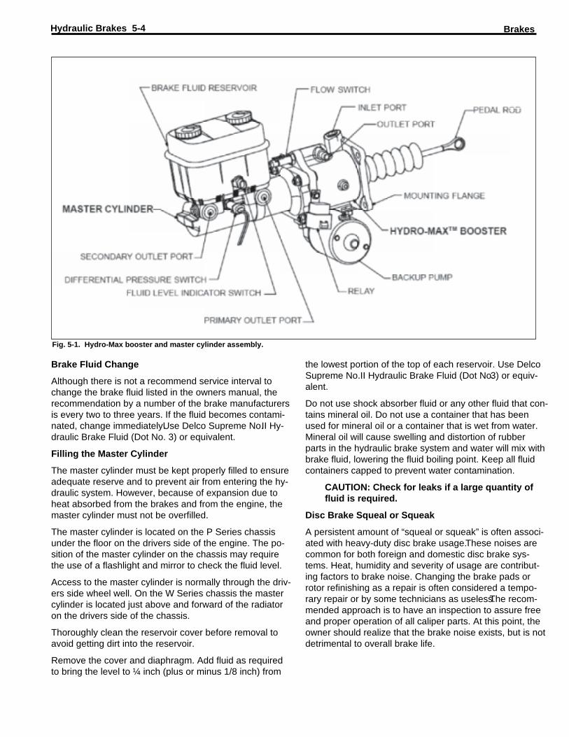
The hydraulic brake booster is supplied hydraulic pressurefrom the power steering pump assisting with the move-ment of the pushrod into the master cylinder. This in turnlowers the amount of effort required by the operator.
HYDRO-MAX BY BOSCH
The Hydro-Max system is utilized on all W Series chassis,figure 5-1. It works on the same principle as a Hydro-Boost system but also incorporates a safety feature to re-tain power brake assistance with the engine on or off.Withthe Hydro-Boost type system, the engine must be operat-ing to provide hydraulic pressure from the power steeringpump to assist with the movement of the pushrod into themaster cylinder.The Hydro-Max system also relies on hy-draulic pressure for operation of the hydraulic power brakebooster but has two sources.
The primary source is from the power steering pump, asin the hydro-boost system. The secondary source is anelectric-hydraulic pump mounted on the hydraulic brakebooster.It monitors the hydraulic pressure when the brakeis depressed and activates the electric hydraulic pump ifhydraulic pressure is not available from the power steer-ing pump.
For example, if the engine dies or is turned off a sensordetects no hydraulic pressure in the system and activatesthe electrical/hydraulic motor to provide hydraulic powerbrake assistance for normal brake operation.
BRAKE SYSTEM MAINTENANCE
At periodic intervals the vehicle brake system should beinspected for “pedal travel.” Brake pedal travel is the dis-tance the brake pedal moves toward the floor from the fullyreleased position (foot not applied to the brake).
Brake pedal inspection should be made with the brakes“cold” and with the engine turned off. Depress the brakepedal a minimum of four (4) times to exhaust all vacuumand/or accumulator pressure. Disable the electric pumpon Hydro-Max systems before proceeding.
Applying approximately 90 pounds of pedal pressure, theapproximate distance the brake pedal should travel is asfollows:
- Chassis with disc front and drum rear brakes (JB8)3.5 inches
- Chassis with disc front and rear brakes (JF9) 6.0 inch-es
- Chassis with disc front and rear brakes (JLP & JL9)2.5 inches
Note: Total pedal stroke that would be achievableduring the bleeding process for the JB8 and JF9,P Series, is 9.66 inches.Total pedal stroke for theJLP and JL9 systems, W Series chassis, is 8.3inches.
BRAKING SYSTEMSThere are two brake systems on a Workhorse motor homechassis, the service brakes and the parking brakes. Theservice brakes use hydraulic pressure from a foot-pedal-operated master cylinder to actuate cylinders that applybrakes at each wheel. Fluid lines and hoses connect themaster cylinder with each of the wheel cylinders andcalipers.
Hydraulic pressure created by the master cylinder opera-tion is transmitted through lines and hoses to the wheelcylinders and calipers. The hydraulic pressure forces thepistons in the wheel cylinders and/or calipers outward,causing the brakes to be applied.
Braking action occurs as a result of friction between thebrake lining and the metal surface of the rotor disc or thedrum.
Parking brake system is mechanically operated by a leverand strut or a pedal, which will active the rear brakes onlyor the transmission mounted propshaft drum brake onchassis with 12,300 lb., 14,800 lb., 15,000 lb., 20,700 lb.and 22,000 lb. GVWR.The parking brake on chassis with16,500 lb., 17,000 lb., 18,000 lb. and 24,000 lb. GVWR isreferred to as automatic apply parking brake.This style ofparking brake is spring applied and hydraulically releasedvia an electro-hydraulic pump; refer to the Automatic ApplyParking Brake section for detailed operation.
BRAKE SYSTEM SERVICE
The Workhorse 12,300 lb. GVWR chassis has front discand rear drum brakes, JB8 system.
The 14,800 lb. thru 18,000 lb. GVWR chassis have four-wheel disc brakes, JF9 system.
The 20,700 lb. and 22,000 lb. chassis has four-wheel discbrakes, JLP system.
The 24,000 lb. chassis also has four-wheel disc brakes,JL9 system.
All P Series chassis have a 3-channel Four-Wheel Anti-Lock braking systems standard.
The W Series chassis have a 4-channel Four-Wheel Anti-Lock braking system standard.
HYDRO-BOOST
Hydro-Boost system receives hydraulic pressure from thepower steering pump to assist with the effort required tooperate braking system. Hydro-Boost unit is located be-tween the brake pedal linkage and the master cylinder.When the brake pedal is depressed, linkage moves thepushrod into the master cylinder to create hydraulic brakepressure.
Brakes Hydraulic Brakes 5-3
the lowest portion of the top of each reservoir. Use DelcoSupreme No.II Hydraulic Brake Fluid (Dot No.3) or equiv-alent.
Do not use shock absorber fluid or any other fluid that con-tains mineral oil. Do not use a container that has beenused for mineral oil or a container that is wet from water.Mineral oil will cause swelling and distortion of rubberparts in the hydraulic brake system and water will mix withbrake fluid, lowering the fluid boiling point. Keep all fluidcontainers capped to prevent water contamination.
CAUTION: Check for leaks if a large quantity offluid is required.
Disc Brake Squeal or Squeak
A persistent amount of “squeal or squeak” is often associ-ated with heavy-duty disc brake usage.These noises arecommon for both foreign and domestic disc brake sys-tems. Heat, humidity and severity of usage are contribut-ing factors to brake noise. Changing the brake pads orrotor refinishing as a repair is often considered a tempo-rary repair or by some technicians as useless.The recom-mended approach is to have an inspection to assure freeand proper operation of all caliper parts. At this point, theowner should realize that the brake noise exists, but is notdetrimental to overall brake life.
Brake Fluid Change
Although there is not a recommend service interval tochange the brake fluid listed in the owners manual, therecommendation by a number of the brake manufacturersis every two to three years. If the fluid becomes contami-nated, change immediately.Use Delco Supreme No.II Hy-draulic Brake Fluid (Dot No. 3) or equivalent.
Filling the Master Cylinder
The master cylinder must be kept properly filled to ensureadequate reserve and to prevent air from entering the hy-draulic system. However, because of expansion due toheat absorbed from the brakes and from the engine, themaster cylinder must not be overfilled.
The master cylinder is located on the P Series chassisunder the floor on the drivers side of the engine. The po-sition of the master cylinder on the chassis may requirethe use of a flashlight and mirror to check the fluid level.
Access to the master cylinder is normally through the driv-ers side wheel well. On the W Series chassis the mastercylinder is located just above and forward of the radiatoron the drivers side of the chassis.
Thoroughly clean the reservoir cover before removal toavoid getting dirt into the reservoir.
Remove the cover and diaphragm. Add fluid as requiredto bring the level to ¼ inch (plus or minus 1/8 inch) from
BrakesHydraulic Brakes 5-4
Fig. 5-1. Hydro-Max booster and master cylinder assembly.
10. Wait 15 seconds11. Repeat this sequence, including the 15 seconds
wait, until you purge all the air from the wheel cylin-der or caliper.
12. Repeat steps 4-11 at each wheel until you purge allthe air from the brake system.
13. This procedure may use up to a pint of fluid perwheel. Check the master cylinder level every four tosix strokes of the brake pedal in order to avoid run-ning the system dry.
14. Check the pedal for sponginess. Check the brakewarning lamp for an indication of unbalanced pres-sure. Repeat the bleeding procedure in order to cor-rect either of these conditions.
ABS BLEEDING PROCEDURE
Important:
- Use the two-person bleed procedure under the fol-lowing conditions.
- Installed a new Electro-Hydraulic Control Unit(EHCU) or Brake Pressure Modulator Valve(BPMV).
- Air is trapped in the valve body.- Use the vacuum, the pressure and the gravity
bleeding procedures only for base brake bleed-ing.
- Do not drive vehicle until the brake pedal feelsfirm.
1. Complete steps 3-13 in above manual/two-personbleeding procedure.
2. Press the brake pedal firmly and run the Scan ToolFunction Test four times.Release the brake pedal be-tween each test.
3. Bleed all four wheels again using the above manualbleeding procedure steps 3-13. This will remove theremaining air from the brake system.
4. Evaluate the feel for the brake pedal before attempt-ing to drive the vehicle.
5. Bleed the system as many times as necessary inorder to obtain the appropriate feel of the pedal.
HYDRO-BOOST & HYDRO-MAX BLEEDINGPROCEDURE
Whenever the booster is removed and reinstalled, thesteering system should be bled as outlined.
Note: Power steering fluid and brake fluid cannotbe mixed. If the brake seals contact steering fluidor steering seals contact brake fluid, seal dam-age will result.
1. Make sure that the ignition switch is in the UNLOCKposition.
2. Turn the steering full left.3. Fill the power steering fluid to the FULL COLD level.
Leave cap off.4. Raise the front wheels off the ground and support ve-
hicle using suitable safety stands.
Bleeding the Hydraulic System
A bleeding operation is necessary to remove air whenev-er air is introduced into the hydraulic brake system. It isrecommended for a trained service technician to performthis procedure.
It may be necessary to bleed the hydraulic system at allfour wheels if air has been introduced through low fluid orby disconnecting the brake pipes at the master cylinder. Ifa brake pipe is disconnected at any wheel cylinder, thenthat wheel cylinder needs to be bled. If pipes are discon-nected at any fitting located between the master cylinderand the wheel cylinders, then all wheel cylinders servedby the disconnected pipe must be bled.
Note: The following procedure is for manualbleeding of the brakes only. If possible, obtain ap-proved commercial pressure-bleeding equip-ment.
1. Fill the master cylinder reservoir with brake fluid andkeep at least half full during the bleeding procedure.Ensure reservoir cap is secured.
2. If the master cylinder is known or suspected to hav-ing air in the bore, bleed the master cylinder usingthe following procedure. Master cylinder must becompletely bled of air before bleeding wheel cylin-ders or calipers.
a. Disconnect the forward brake pipe connector atthe master cylinder.
b. Allow the brake fluid to flow from the connectorport.
c. Connect the brake pipe connector. Do not tightenthe brake pipe connector.
d. Slowly apply the brake pedal. Allow air to bleedfrom loose connector.
e. Tighten the connector before releasing the brakepedal.
f. Release the break pedal.g. Wait 15 seconds.h. Repeat this sequence; include the 15 second
wait, until you purge all the air from the mastercylinder bore.
i. Repeat this procedure for the rear pipe after youpurge all the air from the forward pipe.
3. Bleed each wheel in the following sequence:
a. Right rear wheel cylinder or caliper.b. Left rear wheel cylinder or caliper.c. Right front wheel caliper.d. Left front wheel caliper.
4. Attach a hose to the wheel cylinder/caliper bleedvalve.
5. Immerse the opposite end of the hose into a contain-er partially filled with clean brake fluid.
6. Slowly apply the brake pedal one time and hold.7. Loosen the bleeder valve in order to purge the air
from the wheel cylinder/caliper.8. Tighten the bleeder valve.9. Slowly release the brake pedal.
Brakes Hydraulic Brakes 5-5

BrakesHydraulic Brakes 5-6
Fig. 5-2. Exploded view of Quadraulic caliper assembly.
CALIPER
The caliper assembly consists of two halves assembledwith four bolts and washers, figure 5-2.
It includes four hydraulic piston bores, two brake pads, twostainless steel lining rail covers installed with button headbolts, a pad retainer spring and bolt, bleeder screw andcrossover tube.
The piston bores contain the pistons, piston seals and pis-ton boots.
The crossover tubes connect the two halves of the caliperpiston to supply brake fluid to the outboard pistons.
SUPPORT
The support assembly includes the ABS sensor bracketattached with two screws. It also has provisions to mountan optional splash shield to protect the rotor and brake as-sembly from road contamination.
HUB/ROTOR
The hub and rotor assemblies consist of a hub and rotor,fitted with bearing cups and wheel attachment studs.
Some rotors are equipped with a cast-in ABS speed sen-sor tooth wheel, typically with 100 slots.Some rotors haveseparate ABS speed sensor tooth wheels attached to therotor with bolts.
Front hub/rotor assemblies can have various ABS speedsensor tooth wheels such as: a separate ring mounted tothe inboard end of the hub, ABS teeth integral to the rotor,or a separate ABS ring attached to the rotor by bolts.
5. Place a drain pan under the vehicle to catch anypower steering fluid that may over flow.
6. With an assistant checking fluid level and condition,turn the steering wheel lock-to-lock at least 40 times.
- Trapped air may cause fluid to overflow. Any fluidthat spills out will need to be cleaned for a properleak check.
- Maintain the fluid level at FULL COLD.- Fluid should be free of any air bubbles. If any air
bubbles are present, check all of the power steer-ing hose fittings for leaks. Repair any leaks andrepeat step 6.
7. Start engine and allow it to idle. Maintain the powersteering fluid level at FULL COLD.
8. Install the power steering reservoir cap.9. Return the front wheels to the straight ahead position.10. Return the front wheels to the ground.11. After allowing the engine to idle for two minutes, fully
turn the steering wheel in both directions and de-press the brake pedal several times.
FOUR PISTON QUADRAULIC DISCBRAKE CALIPERMeritor’s Quadraulic disc brakes have a four-piston, fixed-mount caliper design for use on both front and rear driveaxles. An installation includes four major components —the caliper assembly, support assembly, hub/rotor assem-bly and the attaching hardware.
The inboard pistons apply the inboard pads and the out-board pistons apply the outboard pads.

There are various hub configurations offered to accept the19.5-inch (495.3 mm) eight-hole wheels, as well as 22.5-inch (571.5 mm) 10-hole wheels with the hub piloted orstud piloted system.
BRAKE PAD SERVICE
WARNING
To prevent serious personal injury, always wearsafe eye protection when you perform vehiclemaintenance or service.
Remove Brake Pads
1. Visually inspect all brake pads. Replace pads whenthe remaining lining reaches 1/8-inch (3.175 mm)thickness.
If you replace pads: Replace all disc brake pads at thesame time to maintain original brake balance.
If a complete vehicle pad replacement is not necessaryor desirable: Replace the pads on both wheel endson the same axle.
Replace Brake Pads
1. Raise and support the vehicle.
BRAKE PADRETAINERSPRING BOLT
Fig. 5-3. Pad retainer spring bolt
Fig. 5-4. Compress caliper pistons.
BRAKE HOSEHOLD DOWNCLAMP BOLT
Fig. 5-5. Brake hose hold down bolt.
Brakes Hydraulic Brakes 5-7
2. Remove the wheel and tire assembly according tomanufacturer’s recommendation.
3. Remove the master cylinder reservoir filler cap.Checkthe brake fluid level in the reservoir. If necessary, re-move fluid to keep the reservoir from overflowingwhen compressing pistons into the caliper.
4. Remove the pad retainer spring bolt, figure 5-3.5. Compress the caliper pistons, figure 5-4.6. Remove the brake pads.
BRAKE CALIPER SERVICE
WARNING
Park the vehicle on a level surface. Block thewheels to prevent the vehicle from moving. Sup-port the vehicle with safety stands. Do not work
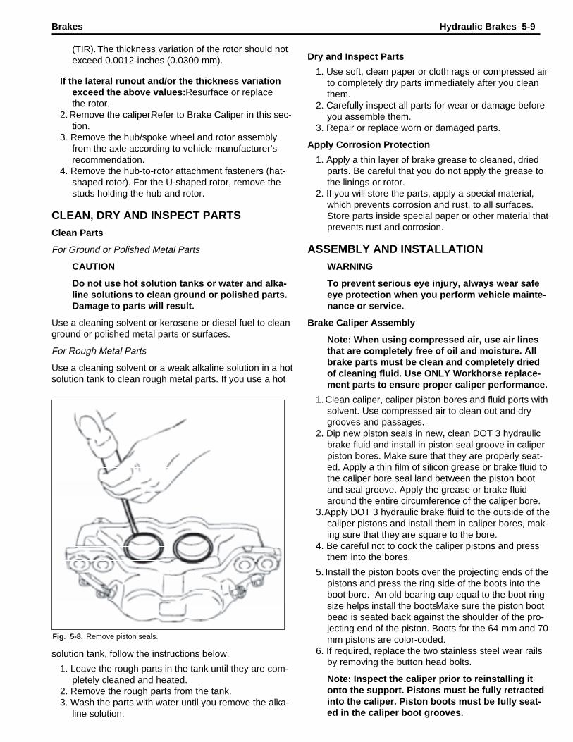
3. Push all four pistons to the bottom of their bores.4.Remove the piston boots by prying the metal ring por-
tion of the boot out of the bore with a screwdriver.Use care to avoid damage to the piston or bore. Dis-card the boots.
under a vehicle supported only by jacks. Jackscan slip and fall over. Serious personal injury canresult.
1. Raise and support the vehicle.2. Remove the tire and wheel assembly according to
manufacturer’s instructions.3. Remove the brake hose hold down clamp bolt, if
equipped, figure 5-5.4. Remove the brake hose/tube from the caliper.5. Remove four caliper-to-support assembly bolts.
Do not disassemble the four bolts joining the twohalves of the caliper.
Disassemble and Overhaul the Brake Caliper
1. Remove the brake caliper. Refer to Brake Caliper inthis section.
2. Drain all fluid from the caliper.
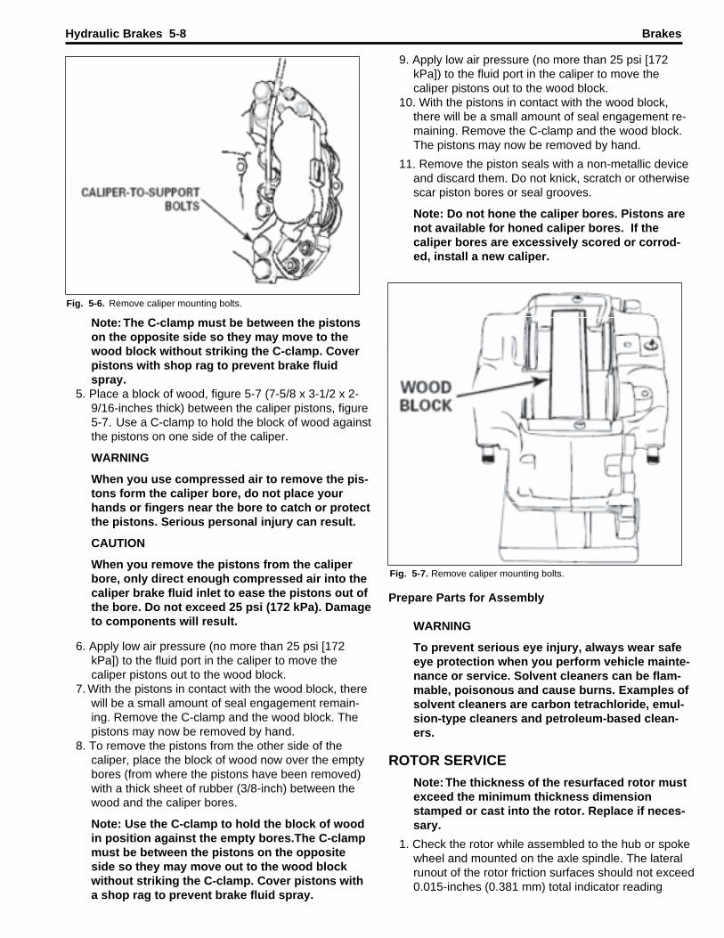
9. Apply low air pressure (no more than 25 psi [172kPa]) to the fluid port in the caliper to move thecaliper pistons out to the wood block.
10. With the pistons in contact with the wood block,there will be a small amount of seal engagement re-maining. Remove the C-clamp and the wood block.The pistons may now be removed by hand.
11. Remove the piston seals with a non-metallic deviceand discard them. Do not knick, scratch or otherwisescar piston bores or seal grooves.
Note: Do not hone the caliper bores. Pistons arenot available for honed caliper bores. If thecaliper bores are excessively scored or corrod-ed, install a new caliper.
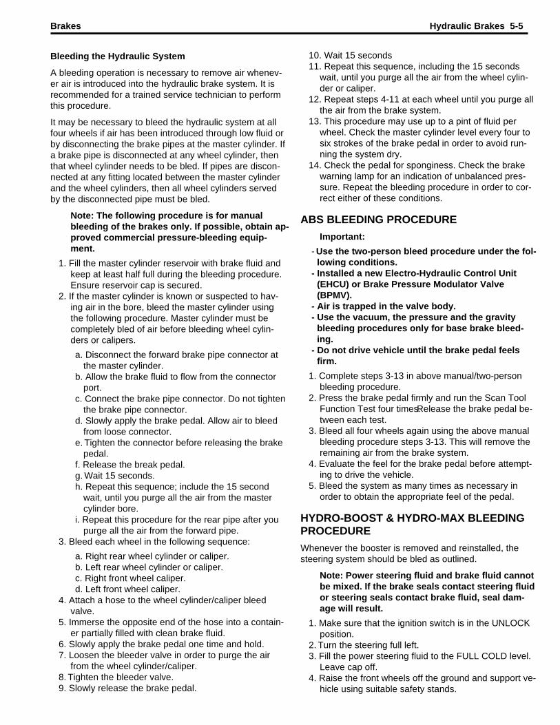
Note: The C-clamp must be between the pistonson the opposite side so they may move to thewood block without striking the C-clamp. Coverpistons with shop rag to prevent brake fluidspray.
5. Place a block of wood, figure 5-7 (7-5/8 x 3-1/2 x 2-9/16-inches thick) between the caliper pistons, figure5-7. Use a C-clamp to hold the block of wood againstthe pistons on one side of the caliper.
WARNING
When you use compressed air to remove the pis-tons form the caliper bore, do not place yourhands or fingers near the bore to catch or protectthe pistons. Serious personal injury can result.
CAUTION
When you remove the pistons from the caliperbore, only direct enough compressed air into thecaliper brake fluid inlet to ease the pistons out ofthe bore. Do not exceed 25 psi (172 kPa). Damageto components will result.
6. Apply low air pressure (no more than 25 psi [172kPa]) to the fluid port in the caliper to move thecaliper pistons out to the wood block.
7. With the pistons in contact with the wood block, therewill be a small amount of seal engagement remain-ing. Remove the C-clamp and the wood block. Thepistons may now be removed by hand.
8. To remove the pistons from the other side of thecaliper, place the block of wood now over the emptybores (from where the pistons have been removed)with a thick sheet of rubber (3/8-inch) between thewood and the caliper bores.
Note: Use the C-clamp to hold the block of woodin position against the empty bores.The C-clampmust be between the pistons on the oppositeside so they may move out to the wood blockwithout striking the C-clamp. Cover pistons witha shop rag to prevent brake fluid spray.
BrakesHydraulic Brakes 5-8
Fig. 5-6. Remove caliper mounting bolts.
Fig. 5-7. Remove caliper mounting bolts.
Prepare Parts for AssemblySection 4 Prepare Parts for Assembly
WARNING
To prevent serious eye injury, always wear safeeye protection when you perform vehicle mainte-nance or service. Solvent cleaners can be flam-mable, poisonous and cause burns. Examples ofsolvent cleaners are carbon tetrachloride, emul-sion-type cleaners and petroleum-based clean-ers.
ROTOR SERVICE
Note: The thickness of the resurfaced rotor mustexceed the minimum thickness dimensionstamped or cast into the rotor. Replace if neces-sary.
1. Check the rotor while assembled to the hub or spokewheel and mounted on the axle spindle. The lateralrunout of the rotor friction surfaces should not exceed0.015-inches (0.381 mm) total indicator reading
Dry and Inspect Parts
1. Use soft, clean paper or cloth rags or compressed airto completely dry parts immediately after you cleanthem.
2. Carefully inspect all parts for wear or damage beforeyou assemble them.
3. Repair or replace worn or damaged parts.
Apply Corrosion Protection
1. Apply a thin layer of brake grease to cleaned, driedparts. Be careful that you do not apply the grease tothe linings or rotor.
2. If you will store the parts, apply a special material,which prevents corrosion and rust, to all surfaces.Store parts inside special paper or other material thatprevents rust and corrosion.
ASSEMBLY AND INSTALLATION
WARNING
To prevent serious eye injury, always wear safeeye protection when you perform vehicle mainte-nance or service.
Brake Caliper Assembly
Note: When using compressed air, use air linesthat are completely free of oil and moisture. Allbrake parts must be clean and completely driedof cleaning fluid. Use ONLY Workhorse replace-ment parts to ensure proper caliper performance.
1. Clean caliper, caliper piston bores and fluid ports withsolvent. Use compressed air to clean out and drygrooves and passages.
2. Dip new piston seals in new, clean DOT 3 hydraulicbrake fluid and install in piston seal groove in caliperpiston bores. Make sure that they are properly seat-ed. Apply a thin film of silicon grease or brake fluid tothe caliper bore seal land between the piston bootand seal groove. Apply the grease or brake fluidaround the entire circumference of the caliper bore.
3.Apply DOT 3 hydraulic brake fluid to the outside of thecaliper pistons and install them in caliper bores, mak-ing sure that they are square to the bore.
4. Be careful not to cock the caliper pistons and pressthem into the bores.
5. Install the piston boots over the projecting ends of thepistons and press the ring side of the boots into theboot bore. An old bearing cup equal to the boot ringsize helps install the boots.Make sure the piston bootbead is seated back against the shoulder of the pro-jecting end of the piston. Boots for the 64 mm and 70mm pistons are color-coded.
6. If required, replace the two stainless steel wear railsby removing the button head bolts.
Note: Inspect the caliper prior to reinstalling itonto the support. Pistons must be fully retractedinto the caliper. Piston boots must be fully seat-ed in the caliper boot grooves.
(TIR). The thickness variation of the rotor should notexceed 0.0012-inches (0.0300 mm).
If the lateral runout and/or the thickness variationexceed the above values:Resurface or replacethe rotor.
2. Remove the caliper.Refer to Brake Caliper in this sec-tion.
3. Remove the hub/spoke wheel and rotor assemblyfrom the axle according to vehicle manufacturer’srecommendation.
4. Remove the hub-to-rotor attachment fasteners (hat-shaped rotor). For the U-shaped rotor, remove thestuds holding the hub and rotor.
CLEAN, DRY AND INSPECT PARTS
Clean Parts
For Ground or Polished Metal Parts
CAUTION
Do not use hot solution tanks or water and alka-line solutions to clean ground or polished parts.Damage to parts will result.
Use a cleaning solvent or kerosene or diesel fuel to cleanground or polished metal parts or surfaces.
For Rough Metal Parts
Use a cleaning solvent or a weak alkaline solution in a hotsolution tank to clean rough metal parts. If you use a hot
Brakes Hydraulic Brakes 5-9
Fig. 5-8. Remove piston seals.
solution tank, follow the instructions below.
1. Leave the rough parts in the tank until they are com-pletely cleaned and heated.
2. Remove the rough parts from the tank.3. Wash the parts with water until you remove the alka-
line solution.

WARNING
To prevent serious eye injury, always wear safeeye protection when you perform vehicle mainte-nance or service.
COMPONENT INSPECTION
Caliper
1. Clean the area around the brake hose. Use brakeparts cleaner.
2. Inspect the heat shields (previous style only) for wearand damage. Replace worn or damaged shields.
3. Inspect the caliper lining spacers for wear and dam-age. Replace worn or damaged spacers.
4. Inspect the housing for cracks or damage. Replace acracked or damaged housing.
CAUTION
The OUTSIDE diameter of the piston is thecaliper’s primary sealing surface and is manufac-tured to very close tolerances. Replace a pistonif the OUTSIDE diameter is damaged. Do not re-finish or use abrasives, including an emery cloth,on the piston. Damage to components can result.
5. Inspect the OUTSIDE diameter of the pistons forscoring, nicks, corrosion, wear and damage. If any ofthese conditions are evident:Replace the pistons.Donot refinish or use abrasives.
6. Inspect the caliper bore for scoring, nicks,corrosion,wear and damage. If any of these conditions are ev-ident: Replace the caliper.
CAUTION
Use a crocus cloth to remove minor stains andcorrosion from the caliper bore. Do not use abra-sives, including an emery cloth. If you cannot re-move minor stains and corrosion, replace thecaliper bore to avoid damage to components.
7. Inspect the caliper bore for minor stains and corro-sion. If these conditions are evident: Use a crocuscloth to remove stains or corrosion. Clean the caliperbore after using a crocus cloth.Do not use abrasives,including an emery cloth.If you cannot remove stainsand corrosion from the caliper bore: Replace thecaliper.
Caliper Mounting Plate
1.Inspect caliper mounting plate area for rust, corrosion.Replace a damaged or worn mounting plate.
2. Use a wire brush to clean the caliper mounting area.3. Inspect the mounting plate for cracks or elongated
bolt holes. If these conditions are evident: Replacethe mounting plate.
Rotor Installation
NOTE: Do not resurface a new replacement rotor.
1. To install, reverse the removal processes, makingsure that the mating surfaces of the hub or spokewheel and rotor are clean and free of rust build-up.
2. Check the rotor for lateral runout. If the lateral runoutexceeds 0.015-inches (0.381 mm), the rotor may berotated to a different mounting hole position on thehub or spoke wheel to reduce the value.
Caliper Installation
1. Inspect the caliper for leakage, damage or defects topiston seals or pistons. If leakage, damage or defectis found, caliper disassembly may be required.
2. To install, reverse the removal process.3. Bleed the brake system and road test the vehicle.
Brake Pad Installation
1. Inspect the rotor for scoring, warping, cracks, bluing,heat spots or other damage or defects and minimumthickness. Repair or replace if necessary.
2. Inspect the disc brake calipers for leakage, damageor defects to piston boots, seals or pistons. Replaceor repair the parts as required.
3. Clean and inspect the lining rail covers. If they areworn, they must be replaced.
Note: The inboard and outboard brake pads areidentical, except when they are equipped with amechanical wear sensor.
4. Install the brake pads. Ensure that the friction surfaceis against the rotor.Install the pad retainer spring andtighten the bolt to 30 lb-ft (40 N•m) of torque.
Note: Brake pad clearance adjustment is auto-matic.
5. Fill the master cylinder reservoir with new, clean,high-performance DOT 3 brake fluid or equivalent.Make several brake applications to move the brakepistons and linings out into contact with the brake ro-tors.
6. Recheck master cylinder reservoir and top off as nec-essary to manufacturer’s recommended level.
7. Bleed the brake system.8. Install the tire and wheel assembly.9. Lower the vehicle and road test for correct operation.
Support Installation
1. Install the support mounting bolts.Tighten the bolts tothe specified torque.
2. Install the ABS sensor. Tighten the bolt to 8 lb-ft (11N•m).
3. Install the hub and rotor assembly.4. Install the splash shield, if equipped.5. Install the caliper as described under Caliper in this
section.
BrakesHydraulic Brakes 5-10

Equalize to recommended pressures. Install correctsize tires with good tread.
- Excessive rotor parallelism or runout Resurface or re-place rotor.
- Restricted hose or line. Examine the hoses and lines,and replace as necessary.
- Front end out of alignment Reset alignment.
Leaky Caliper
- Cylinder bore surface scored or corroded Disassem-ble calipers, clean bore and replace seals and boots.
- Caliper piston seal damaged or worn Disassemblecalipers and install new seals and boots.
- Caliper piston damaged Replace piston.
No Braking Effect or Excessive Pedal Travel
Reservoir fluid level low Check for causes of fluid leak, re-pair as required and refill the reservoir. Bleed system asneeded.
- Air in the hydraulic system Bleed the system.- Bleeder screw loose or open Bleed the system and
tighten the bleeder screw.- Caliper piston seal damaged Disassemble the caliper
and replace the piston seals. Replace piston if dam-aged.
- Excessive rotor runout or bent rotor Check rotor withdial indicator. Install new rotor if runout exceeds max-imum specified.
- Bad or excessively loose wheel bearings Adjust or re-place bearings as needed.
- Poor quality brake fluid Drain and clean system. Re-place with recommended brake fluid.
- Weak brake hose that expands under pressure Re-place defective hoses.
Brake Noise — Chatter
- Excessive lateral runout of rotor Check the runout witha dial indicator. Install new rotor if the runout exceedsthe maximum specified.
- Lack of rotor parallelism Check the parallelism with amicrometer. Resurface or install new rotor as re-quired.
- Loose wheel bearing Readjust the bearing to speci-fied torque.
Brake Noise — Scraping
- Rust or mud build-up on edges of rotor and on caliperhousing
- Clean or replace as necessary.- Worn pad or pad installed backward Replace pads in
axle sets only with friction surface against the rotor.- Faulty caliper alignment permitting rotor to scrape on
housing- Correct the alignment.
Brake Noise — Groan
- Pressure on the brake pedal too light Slightly increase
BRAKE SYSTEM BLEEDING PROCEDURE
Refer to ABS section for information on ABS bleeding in-structions.
1. Check the master cylinder reservoir and fill, if neces-sary, with DOT 3 or DOT 4 brake fluid.
2. Bleed brakes in the following order:right rear, left rear,right front and left front.
3. Each four-piston caliper is equipped with two bleederscrews. Loosen the inner bleeder screw (which is al-ways on the top) and purge the air.Tighten it loosely.
4. Open the outer bleeder screw and purge the air andtighten the bleeder screw to 9-12 lb-ft (12.2-16.3N•m).
5. Now again open the inner bleeder screw and purgethe air and tighten the bleeder screw to 9-12 lb-ft(12.2-16.3 N•m).
6. Repeat this procedure for all other brakes in the se-quence specified in Step 2.
7. Test brakes prior to returning vehicle to service.A firmpedal should be felt during brake application.
T TTROUBLESHOOTING
BRAKES
Conditions Possible Causes Correction
Excessive Pedal Effort
Pads worn below minimum thickness Install new pads.Faded, overheated condition, glazed pads, “blued” orheat-checked rotors Replace the rotor and/or reface padsif sufficient lining remains.Grease, oil and/or brake fluid onlinings Install new pads in axle sets. Seized or frozen pis-tons Disassemble calipers and free pistons, or replacecaliper.
Pedal Pulsation (Brake Roughness or Chatter)
- Excessive lateral runout of brake rotor Check with dialindicator. Install new rotor if runout exceeds the max-imum specified.
- Excessive out-of-parallelism of brake rotor Check theparallelism (rotor thickness variation) with micrometerand resurface the rotor, or install new rotor if the par-allelism exceeds the maximum allowed.
- Loose or worn steering or suspension parts Replaceparts and realign. Excessive front bearing clearanceReadjust the bearing to specifications.
Vehicle Pulls to One Side
- Brake fluid, oil and/or grease on linings Install newpads in axle sets.
- Unmatched linings, uneven lining wear, distorted padsInstall new pads in axle sets.
- Rough rotor surfaces on one rotor Resurface or re-place rotor in axle sets. Seized or frozen pistons Dis-assemble caliper and repair or replace.
- Loose caliper mounting bolts Tighten to specifications.Uneven tire pressure, tread wear or size, right to left
Brakes Hydraulic Brakes 5-11
8. Fasten a dial indicator to the steering knuckle so thatthe indicator button contacts the brake rotor surfaceabout 25.4 mm (1 in) from the outer edge.
9. Set the dial indicator to zero.10.Turn the wheel one complete revolution.11.Observe
the runout indicated on the dial.12.The (TIR) must not exceed 0.13 mm (0.005 in).13. Adjust the wheel bearings. Refer to Wheel Bearing
Adjustment (Independent) or Wheel Bearing Adjust-ment (I-Beam).
Brake Rotor Tolerance
During the manufacture of the brake rotor, tolerances ofthe braking surfaces for flatness, parallelism, and lateralrunout are closely held. The maintenance of close toler-ances on the shape of the braking surfaces is necessaryin order to prevent brake roughness or brake pedal pulsa-tion.
In addition to these tolerances, the surface finish must beheld to a specified range of 60 Ra roughness or less.Con-trolling the braking surface finish avoids problems of hardpedal application, excessive brake fade, brake and steer-ing pulls, and erratic performance. In addition, control ofthe surface finish can improve brake lining life.
Light scoring of the brake rotor surfaces not exceeding 1.5mm (0.06 in) in depth is normal and not detrimental tobrake operation.
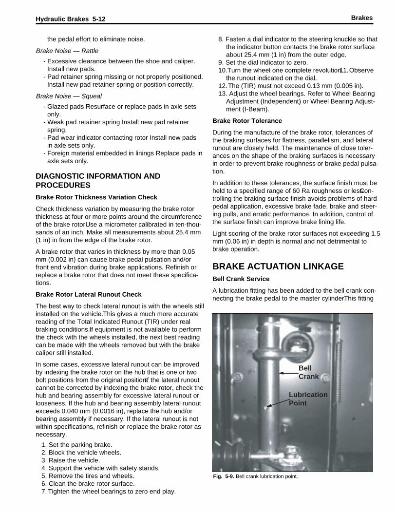
BRAKE ACTUATION LINKAGEBell Crank Service
A lubrication fitting has been added to the bell crank con-necting the brake pedal to the master cylinder.This fitting
the pedal effort to eliminate noise.
Brake Noise — Rattle
- Excessive clearance between the shoe and caliper.Install new pads.
- Pad retainer spring missing or not properly positioned.Install new pad retainer spring or position correctly.
Brake Noise — Squeal
- Glazed pads Resurface or replace pads in axle setsonly.
- Weak pad retainer spring Install new pad retainerspring.
- Pad wear indicator contacting rotor Install new padsin axle sets only.
- Foreign material embedded in linings Replace pads inaxle sets only.
DIAGNOSTIC INFORMATION ANDPROCEDURES
Brake Rotor Thickness Variation Check
Check thickness variation by measuring the brake rotorthickness at four or more points around the circumferenceof the brake rotor.Use a micrometer calibrated in ten-thou-sands of an inch. Make all measurements about 25.4 mm(1 in) in from the edge of the brake rotor.
A brake rotor that varies in thickness by more than 0.05mm (0.002 in) can cause brake pedal pulsation and/orfront end vibration during brake applications. Refinish orreplace a brake rotor that does not meet these specifica-tions.
Brake Rotor Lateral Runout Check
The best way to check lateral runout is with the wheels stillinstalled on the vehicle.This gives a much more accuratereading of the Total Indicated Runout (TIR) under realbraking conditions.If equipment is not available to performthe check with the wheels installed, the next best readingcan be made with the wheels removed but with the brakecaliper still installed.
In some cases, excessive lateral runout can be improvedby indexing the brake rotor on the hub that is one or twobolt positions from the original position.If the lateral runoutcannot be corrected by indexing the brake rotor, check thehub and bearing assembly for excessive lateral runout orlooseness. If the hub and bearing assembly lateral runoutexceeds 0.040 mm (0.0016 in), replace the hub and/orbearing assembly if necessary. If the lateral runout is notwithin specifications, refinish or replace the brake rotor asnecessary.
1. Set the parking brake.2. Block the vehicle wheels.3. Raise the vehicle.4. Support the vehicle with safety stands.5. Remove the tires and wheels.6. Clean the brake rotor surface.7. Tighten the wheel bearings to zero end play.
BrakesHydraulic Brakes 5-12
LubricationPoint
BellCrank
Fig. 5-9. Bell crank lubrication point.

requires lubrication at each chassis service.
Vehicles without the lubrication fitting require the followingsteps to lubricate the bell crank shaft:
1. Disconnect the linkage from the bell crank assembly.
2. Remove the bolt retaining the bell crank shaft in thehousing.
3. Remove the shaft from the housing and inspect fordamage or scoring. If the shaft is damaged, replacethe bell crank assembly.
4. Apply a liberal coat of chassis lube to the shaft andinto the housing bore.
5. Reinstall the shaft and replace the retaining bolt.6. Lubricate the linkage pivot points before reconnect-
ing.7. Check proper operation of the brake linkage to ensure
free operation.
Note: If the shaft cannot be completely removeddue to interference with the body panels, pull theshaft out as far as possible and complete steps 4through 7.
Brakes Hydraulic Brakes 5-13
In all cases, the vehicle manufacturer’s service manualmust be used for any repair instructions.
Brake system warning lights and buzzers are unique tothe vehicle manufacturer. The Brake Warning Light andBuzzer Do Not Shut Off flow chart offered in this guide isgeneric and may not apply to all vehicles. The vehiclemanufacturer’s service manual must be consulted in orderto determine the proper function of these warning devices.
Exclusions
The ABS portion of the hydraulic brake system is not ad-dressed in detail in this guide since the ABS hardware andsoftware are unique to the specific vehicle manufacturer.Any diagnosis or repair needs to be done in accordancewith the vehicle manufacturer’s ABS service manual.
BOSCH HYDRAULIC BRAKE DIAGNOSIS
IMPORTANT REMINDER: The first step in diag-nosing any customer complaint is to confirm thecustomer’s complaint and determine which cate-gory applies.
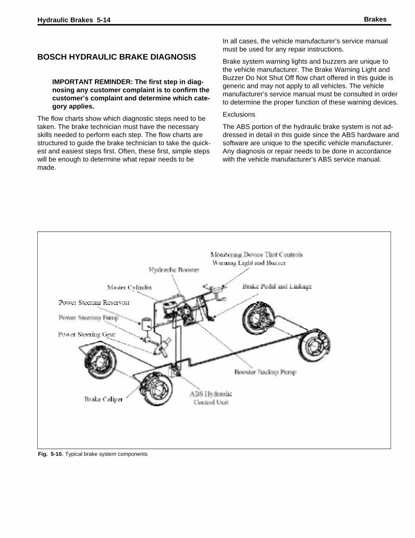
The flow charts show which diagnostic steps need to betaken. The brake technician must have the necessaryskills needed to perform each step. The flow charts arestructured to guide the brake technician to take the quick-est and easiest steps first. Often, these first, simple stepswill be enough to determine what repair needs to bemade.
BrakesHydraulic Brakes 5-14
Fig. 5-10. Typical brake system components

Brakes Hydraulic Brakes 5-15
Fig. 5-11. Typical electrcial system components.
Warning Light and Buzzer Do Not Shut Off
The light and buzzer come on together, typically in re-
sponse to signals from the parking brake switch, boosterflow switch, master cylinder fluid level indicator switch, themaster cylinder differential pressure switch or booster
Fig. 5-12. Warnng light and buzzer do not shut off.
backup pump (See Figure 2).
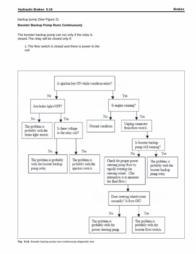
Booster Backup Pump Runs Continuously
The booster backup pump can run only if the relay isclosed.The relay will be closed only if:
1. The flow switch is closed and there is power to thecoil
BrakesHydraulic Brakes 5-16
Fig. 5-13. Booster backup pump runs continuously diagnostic tree.
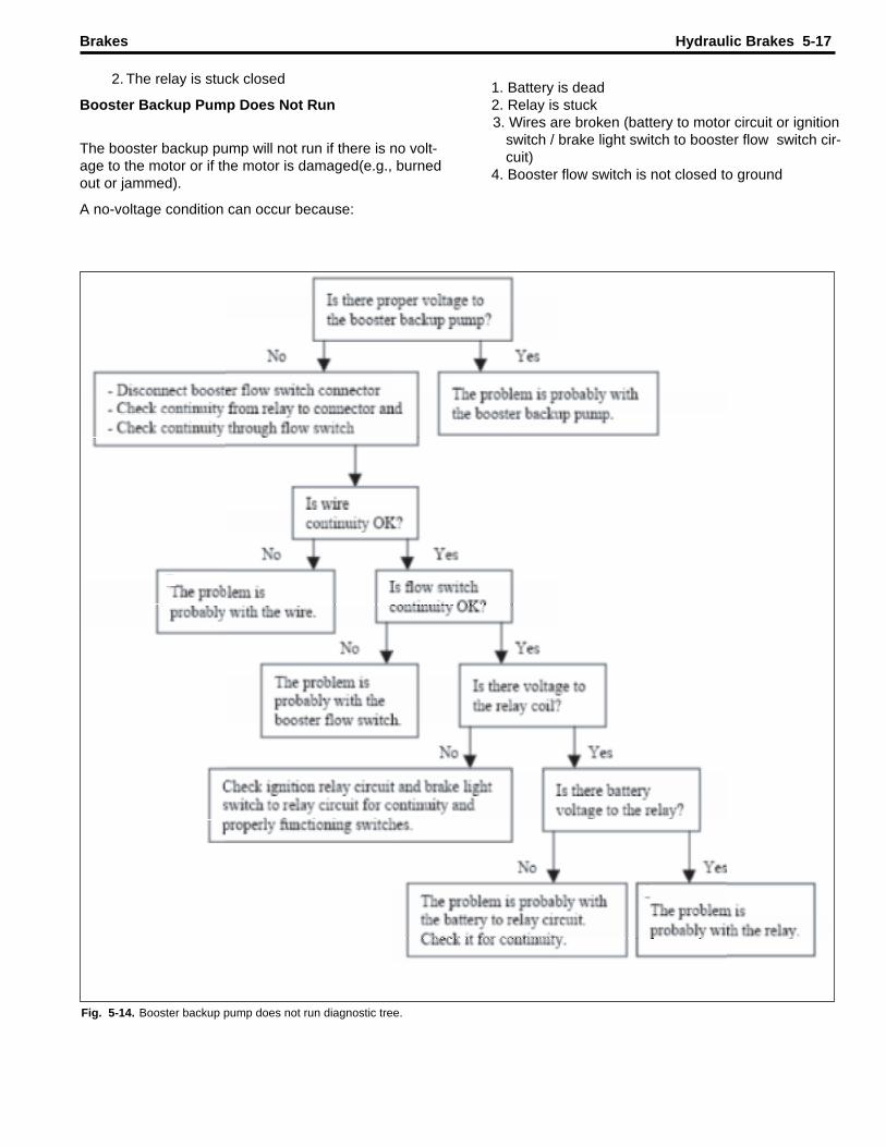
1. Battery is dead2. Relay is stuck3. Wires are broken (battery to motor circuit or ignition
switch / brake light switch to booster flow switch cir-cuit)
4. Booster flow switch is not closed to ground
2. The relay is stuck closed
Booster Backup Pump Does Not Run
The booster backup pump will not run if there is no volt-age to the motor or if the motor is damaged(e.g., burnedout or jammed).
A no-voltage condition can occur because:
Brakes Hydraulic Brakes 5-17
Fig. 5-14. Booster backup pump does not run diagnostic tree.
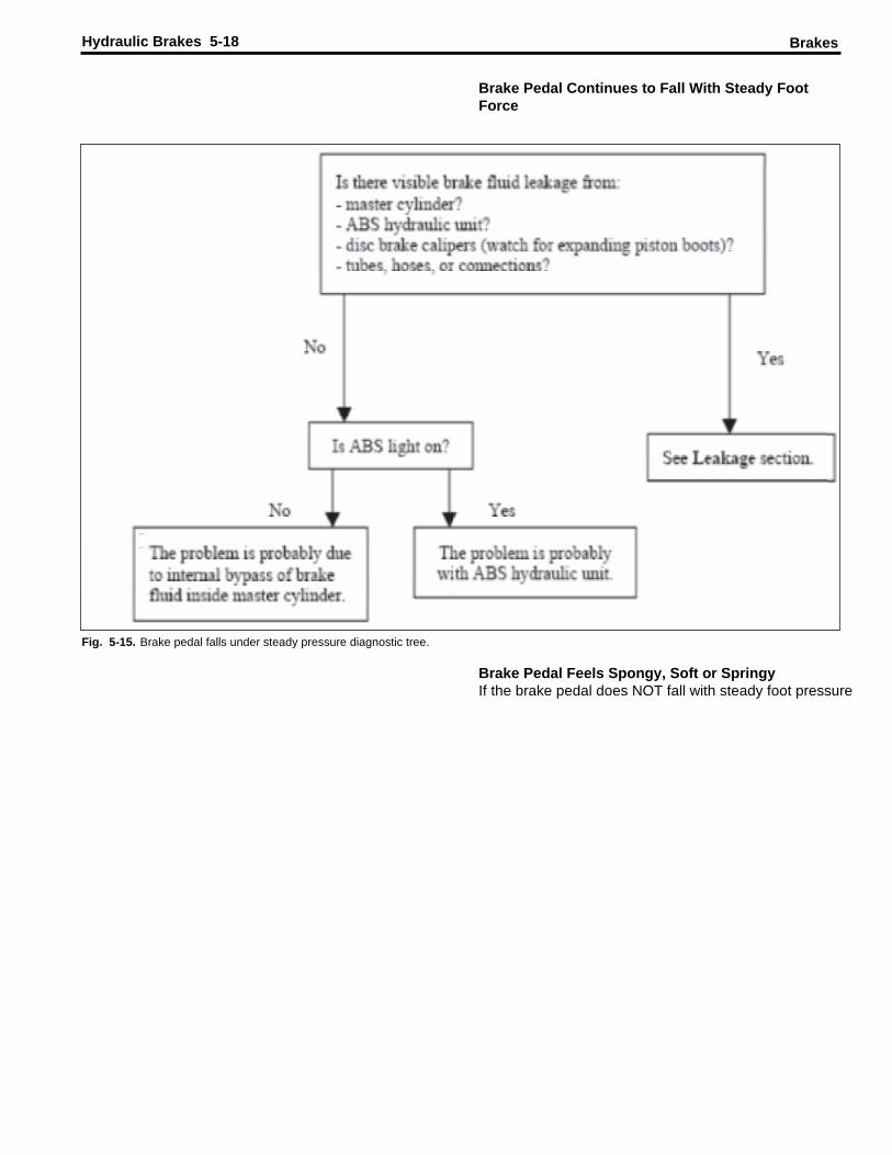
Brake Pedal Continues to Fall With Steady FootForce
BrakesHydraulic Brakes 5-18
Fig. 5-15. Brake pedal falls under steady pressure diagnostic tree.
Brake Pedal Feels Spongy, Soft or SpringyIf the brake pedal does NOT fall with steady foot pressure
but feels spongy, soft or springy, the problem is probablycaused by air trapped in the brake fluid system. Start bybleeding the brake system at the caliper furthest from themaster cylinder and work from the back to the front of thevehicle.
Brakes Hydraulic Brakes 5-19
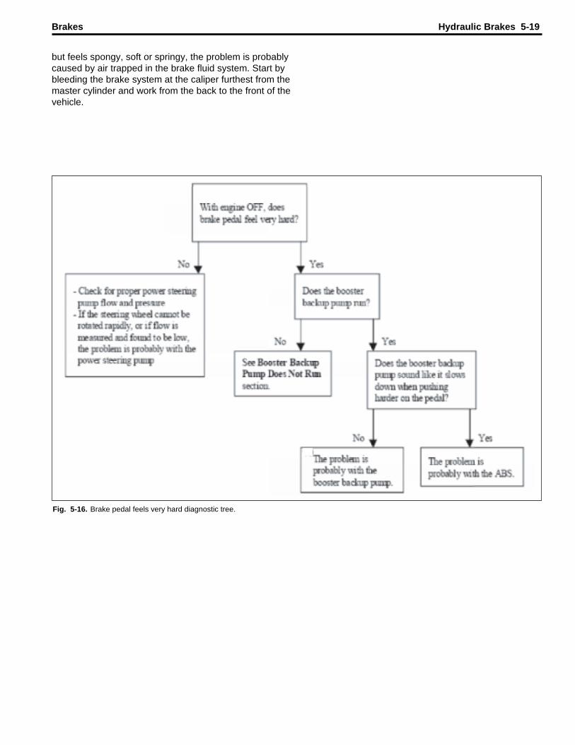
Fig. 5-16. Brake pedal feels very hard diagnostic tree.
Brake Pedal Feels Very Hard
The most common reasons for a very hard brake pedal
BrakesHydraulic Brakes 5-20
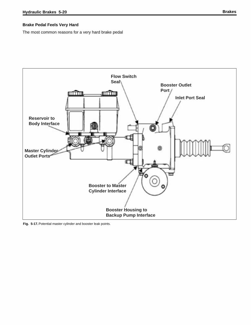
Flow SwitchSeal
Booster OutletPort
Inlet Port Seal
Reservoir toBody Interface
Master CylinderOutlet Ports
Booster to MasterCylinder Interface
Booster Housing toBackup Pump Interface
Fig. 5-17.Potential master cylinder and booster leak points.

are:
1. Insufficient flow or pressure from the power steeringpump
2. The ABS hydraulic unit is blocking the flow of brake
Brakes Hydraulic Brakes 5-21
Fig. 5-18. Leakage diagnostic tree. (1 of 3)

fluid to the calipers
Potential Master Cylinder and Booster Leak Points
BrakesHydraulic Brakes 5-22
Fig. 5-19.Leakage diagnostic tree. (2 of 3)
Leakage
Brakes Hydraulic Brakes 5-23
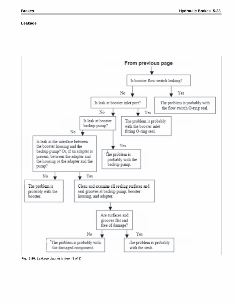
Fig. 5-20. Leakage diagnostic tree. (3 of 3)

Most external leakage is easy to detect by wetness and/orappearance of fluid drops. However, slight dampness (nodrops or wetness) may not indicate a leak.
Leakage (continued)
Brake fluid mixes with water.Power steering fluid floats onwater.
Leakage (continued)Brake Drag
BrakesHydraulic Brakes 5-24
Continued on Page 5-26
Fig. 5-21. Brake drag diagnostic tree. (1 of 4)

Possible Causes of Brake Drag:
1. Booster does not return2. Master cylinder does not return3. Brake pedal does not return4. ABS traps pressure5. Brake hoses and tubes collapsed or kinked
Brakes Hydraulic Brakes 5-25
Fig. 5-22 Brake drag diagnostic tree. (2 of 4)
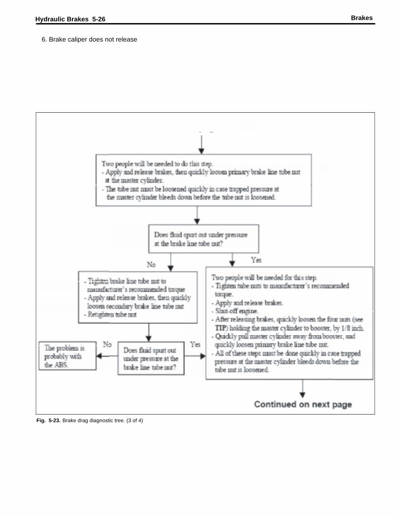
6. Brake caliper does not release
BrakesHydraulic Brakes 5-26
Fig. 5-23. Brake drag diagnostic tree. (3 of 4)
Brakes Hydraulic Brakes 5-27
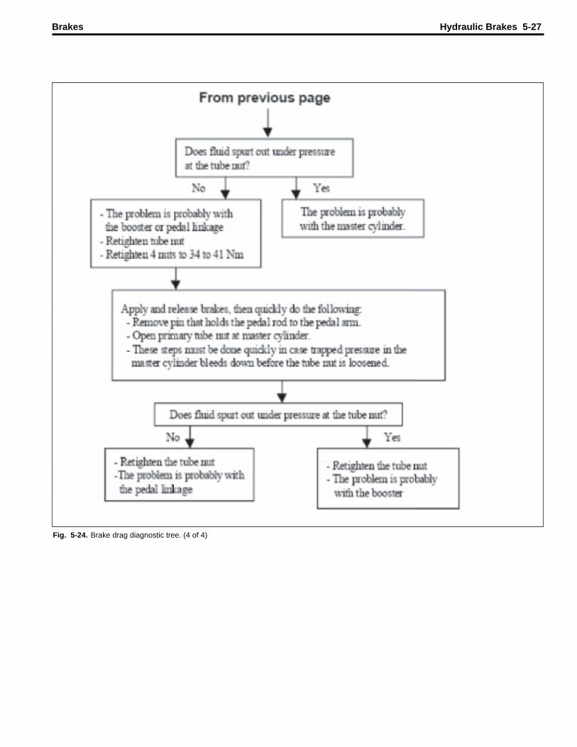
Fig. 5-24. Brake drag diagnostic tree. (4 of 4)
Brake Drag
BrakesHydraulic Brakes 5-28
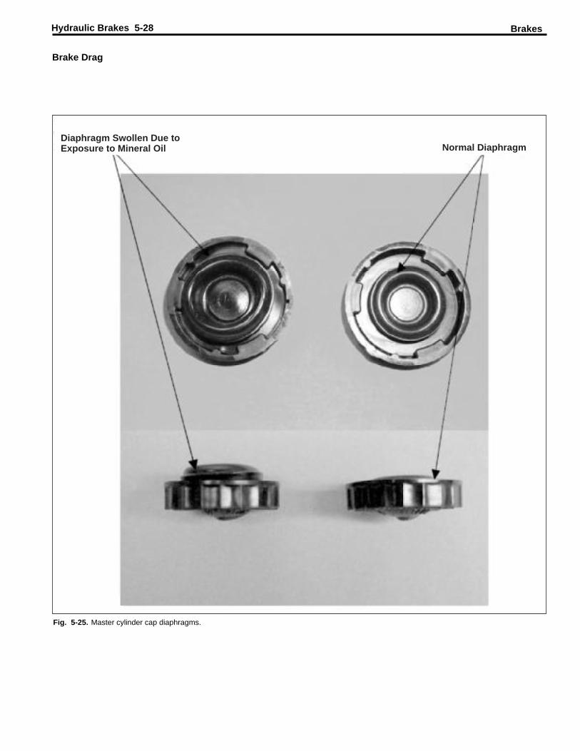
Diaphragm Swollen Due toExposure to Mineral Oil Normal Diaphragm
Fig. 5-25. Master cylinder cap diaphragms.
Prior to moving master cylinder 1/8 inch away from boost-er, loosen two diagonally opposed nuts that hold the mas-ter cylinder to the booster, by 1/8 inch. Have a power toolready to loosen the remaining two nuts after the brakeshave been applied and released.
Brake Drag Continued
Brakes Hydraulic Brakes 5-29
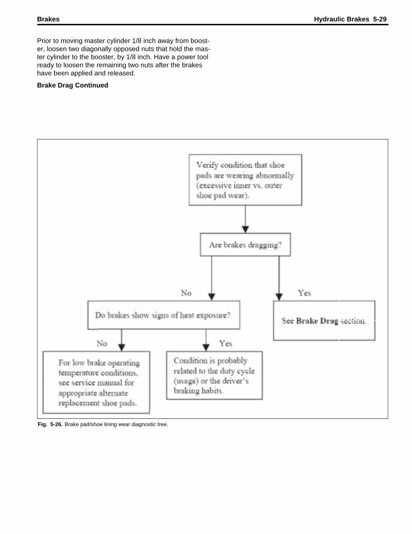
Fig. 5-26. Brake pad/shoe lining wear diagnostic tree.

Brakes J72 Auto/Apply Park Brake System 5-1
Section 5 J72 Auto/Apply Park Brake System Service
J72 Park Brake System Service ............................................................................................... 5-3 System Overview...................................................................................................................... 5-3 Auto-Apply Warning Lamp........................................................................................................ 5-4 Park Brake Warning Lamp........................................................................................................ 5-4 Park Brake Pull Switch ............................................................................................................. 5-4 Park Brake Pump Motor Relay ................................................................................................. 5-4 Ignition Relay............................................................................................................................ 5-4 Actuator Assembly.................................................................................................................... 5-4 Electronic Control Module......................................................................................................... 5-4 Pump/Motor Assembly.............................................................................................................. 5-4 Proportional Solenoid Valve ..................................................................................................... 5-5 Pressure Transducer ................................................................................................................ 5-5 Diagnosis.................................................................................................................................. 5-6 Park Brake System Diagnosis .................................................................................................. 5-6 Park Brake Does Not Hold........................................................................................................ 5-6 Park Brake Will Not Release .................................................................................................... 5-6 Component Replacement ......................................................................................................... 5-8 Park Brake Assembly Replacement ......................................................................................... 5-8 Park Brake Actuator Assembly Replacement ........................................................................... 5-9

5-2 J72 Auto/Apply Park Brake System Brakes
This Page Intentionally Left Blank

Brakes J72 Auto/Apply Park Brake System 5-3 J72 PARK BRAKE SYSTEM SERVICE The J72 park brake system is made up of two major separate components or systems, the actuator and the brake assembly. Each of the components is serviced as an assembly.
SYSTEM OVERVIEW The J72 system incorporates a unique full-circle parking brake. The automatic electric/hydraulic parking system controls the transmission/propeller shaft mounted parking brake. This system consists of a pump motor relay, vehicle ignition relay, electric/hydraulic pump, reservoir, proportional relief solenoid valve, pressure transducer, and an electronic control module (ECM). The ECM monitors seven inputs from the vehicle and controls the pump motor relay, auto-park light, park brake warning light, buzzer, proportional valve, and pressure transducer. The park brake is released by pushing the park brake switch pull-button in and moving the shift lever on the steering column from the park position or select “D”, “N” or “R” on the push button shift control. Notice: Both situations must occur for the brake to release. Once the ECM receives the signals from the transmission and button contacts, the ECM closes the solenoid valve and closes the pump/motor relay allowing current to flow to the motor. The pump/motor then supplies fluid to the brake assembly. The brake assembly includes a friction disc clamped by a piston through force of an internal spring. The fluid pressure acts on the piston overcoming the spring tension that clamps the friction disc, releasing the brake. The pump motor will shut off when the transducer reads the fluid pressure of approximately 1400 psi. The solenoid valve holds pressure in the system while the brake is in a released state. The ECM monitors system pressure from the pressure transducer and energizes the pump motor when system pressure drops below approximately 1200 psi. Putting the shift lever back to park, selecting “P” on the push button shift control, turning off the ignition, or pulling the push/pull switch prompts the ECM to de-energize the solenoid valve dumping fluid back into the reservoir. As the pressure decreases, the spring force clamps the piston back against the friction disc and applies the park brake.
Figure 5-1. J72 Auto Apply Park Brake – Transmission Mounted Brake Assembly

5-4 J72 Auto/Apply Park Brake System Brakes Auto-Apply Warning Lamp The auto-apply warning lamp turns on when the system pressure falls below than 900 psi and the ECM receives the signal from the transmission.
Park Brake Warning Lamp The park brake warning lamp illuminates when system pressure falls below 900 PSI or when the parking brake pull-button is pulled out.
Park Brake Pull Switch The park brake pull switch is mounted on the instrument panel. This is a manual activation switch for the park brake. This switch is normally closed, pushed in. The body manufacturer determines final location of this switch.
Park Brake Pump Motor Relay The park brake pump motor relay is located in the underhood fuse box on the front driver’s side of the radiator core support. It receives ground from the ECM and acts as the automatic control circuit for the high voltage current required to run the pump motor. When the ECM supplies ground to the relay switch, the contacts close to complete the feed circuit to the pump motor.
Ignition Relay The ignition relay is also located in the underhood fuse box on the front driver’s side of the radiator core support. It monitors the vehicle’s ignition switch to turn on/off the supply of the fifteen and forty-five amp fused-lines that the ECM and electric motor use. If the relay was not present, the ECM would be continually powered since it would be directly connected to the batteries.
ACTUATOR ASSEMBLY The actuator assembly controls the pressure in the park brake system to either set or release the park brake. The actuator consists of a mounting bracket and the following components:
Electronic Control Module The electronic control module (ECM) is an analog logic device that monitors the various vehicle conditions then controls the actuator accordingly. It is the “black box” mounted underneath the actuator mounting bracket. It connects to the vehicle via a fourteen pin connector, to the proportional solenoid valve via a two pin connector, and a pressure transducer via a three pin connector. The ECM is powered by two different sources. First, it receives power primarily through a fifteen amp fuse. Secondly, the ECM receives power off of the forty-five amp fused-line that the pump motor relay also uses.
Pump/Motor Assembly The pump/motor assembly consists of an electric motor, geared pump, aluminum port block, and a semi-transparent fluid reservoir. The port block holds the proportional solenoid valve and pressure transducer. The pump provides fluid pressure for the system. A pressure relief valve in the port block limits system pressure to around 1700 psi.
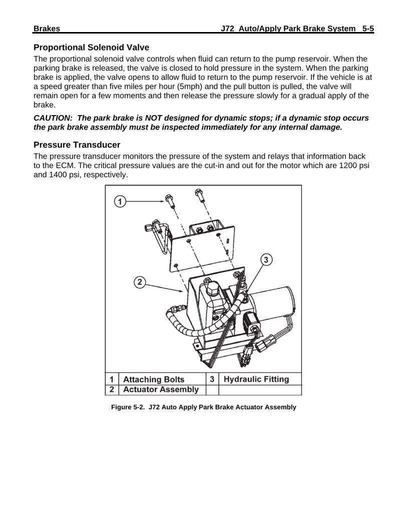
Brakes J72 Auto/Apply Park Brake System 5-5 Proportional Solenoid Valve The proportional solenoid valve controls when fluid can return to the pump reservoir. When the parking brake is released, the valve is closed to hold pressure in the system. When the parking brake is applied, the valve opens to allow fluid to return to the pump reservoir. If the vehicle is at a speed greater than five miles per hour (5mph) and the pull button is pulled, the valve will remain open for a few moments and then release the pressure slowly for a gradual apply of the brake. CAUTION: The park brake is NOT designed for dynamic stops; if a dynamic stop occurs the park brake assembly must be inspected immediately for any internal damage.
Pressure Transducer The pressure transducer monitors the pressure of the system and relays that information back to the ECM. The critical pressure values are the cut-in and out for the motor which are 1200 psi and 1400 psi, respectively.
Figure 5-2. J72 Auto Apply Park Brake Actuator Assembly

5-6 J72 Auto/Apply Park Brake System Brakes DIAGNOSIS
PARK BRAKE SYSTEM DIAGNOSIS Park brake operational concerns fall into two different areas.
• Brake Does Not Hold • Brake Will Not Release
Park Brake Does Not Hold To test the park brake function, conduct the following steps.
1. Choose a LEVEL location away from people, pets, and buildings. 2. Ensure the vehicle is in PARK. 3. Apply the service brake (foot brake) and start the engine. 4. Place the transmission in DRIVE. 5. Apply the park brake by pulling the park brake button out to the applied position. 6. Slowly release the service brake (foot brake).
CAUTION: If the vehicle moves, reapply the foot brake and place the transmission back in PARK. Service the park brake before repeating the test.
7. If the vehicle does not move, GRADUALLY increase the throttle opening to approximately 1,500 RPM for five seconds, then release the throttle and apply the service brake (foot brake).
a. Test results: i. If the brake holds, no further action is required. Note the results of the test
on the Repair Order for future reference. ii. If the brake does not hold, the park brake assembly must be replaced.
8. Apply the service brake (foot brake), then release the park brake. 9. Release and reapply the service brake (foot brake) to relieve any strain in the drivetrain. 10. Place the transmission in PARK. The auto-apply park brake should set. 11. Turn the ignition OFF and remove the key. 12. If the brake did not hold in step 7, chock the wheels and proceed to the repair
instructions.
Park Brake Will Not Release If the J72 park brake will not release, chock the wheels and check the following items.
1. Check the fluid level in the reservoir. Add fluid if the level is below the MIN line. 2. Check the ALT/START fuse. 3. Check the function of the Auto Park Brake Motor Relay by substituting a known good
relay of the same type. 4. Check the function of the Auto Park IGN relay by substituting a known good relay of the
same type. 5. Check the function of the Park Brake Pull Button relay by substituting a known good relay
of the same type. 6. Check for leaks in the hydraulic lines. Correct any leaks found. 7. Check for power to the motor. If power is not present, check for continuity on the power
feed circuit. If power is present, check for continuity on the ground circuit.

Brakes J72 Auto/Apply Park Brake System 5-7
8. Check for motor function by providing battery voltage to pin A of the motor connector and ground to pin B of themotor connector. If the motor does not function, replace it.
9. Perform Park Brake ECM Connector Pin Out Diagnostic Tests: • Pin 1 – Check for battery voltage on ECM Pin 1. If no voltage is present check the
fuse and the circuit. • Pin 2 – Disconnect the harness from the ECM. Connect a test lead from Cavity 2
and ground. The pump motor should operate. If not check the relay and motor circuit.
• Pin 3 – Backprobe cavity 3 and apply the park brake. Power should be present when the brake is applied and the ignition is in the ON position.
• Pin 4 – Backprobe cavity 4 with the brake applied. Ground should be present when the brake is applied.
• Pin 5 – Backprobe Cavity 5 with the brake applied. Ground should be present. • Pin 6 through Pin 8 – Not used. • Pin 9 – Backprobe Cavity 9 with the brake applied. Ground should be present. • Pin 10 – Check for battery voltage on ECM Pin 10. If no voltage is present check
the fuse and the circuit. • Pin 11 – Pin 11 provides the speed signal from the ABS module. • Pin 12 – Check for battery voltage on ECM Pin 10 with the vehicle in PARK. If no
voltage is present check the fuse and the circuit to the PNP switch. • Pin 13 – Backprobe Cavity 9 with the brake applied. Ground should be present. • Pin 14 – Pin 14 supplies the ECM with chassis ground. Backprobe Cavity 14 and
check for ground.
Figure 5-3. J72 Park Brake ECU Pinout Guide

5-8 J72 Auto/Apply Park Brake System Brakes COMPONENT REPLACEMENT
PARK BRAKE ASSEMBLY REPLACEMENT CAUTION: Block the vehicle wheels to prevent movement before servicing the park brake assembly.
Removal Procedure 1. Raise the vehicle and support the vehicle with safety stands. Refer to Lifting and Jacking
the Vehicle in General Information. Important: Ensure the park brake is applied.
2. Remove the propeller shaft. Refer to Two-Piece Propeller Shaft Replacement or Three-Piece Propeller Shaft Replacement.
3. Disconnect the hydraulic line from the brake assembly. Install a suitable plug in the hydraulic line and cap the brake assembly fitting to minimize fluid loss.
4. Remove the center bolt retaining the yoke to the transmission output shaft. Remove the yoke.
Figure 5-4. Removing the Park Brake Assembly
Important: Cap the end of the transmission in order to minimize fluid loss. 5. Inspect the yoke ears for damage and the splines for the following damage:
• Wear • Burrs • Twisting
CAUTION: The park brake assembly weighs approximately 45lbs (20 kg). Use a suitable jack to support the brake before removing the attaching bolts. Failure to do so may result in personal injury.
6. Remove the four bolts attaching the brake assembly to the transmission housing. 7. Remove the brake assembly.

Brakes J72 Auto/Apply Park Brake System 5-9 Installation Procedure Notice: Refer to Fastener Notice in Cautions and Notices.
1. Raise the brake assembly into position and align with the mounting holes in the transmission housing.
2. Install the bolts and washers attaching the brake assembly to the transmission housing. Tighten the bolts and washers to 89 Ib ft (121 Nm).
3. Install the yoke and attaching bolt. Tighten the bolt to 89 Ib ft (121 Nm). 4. Connect the hydraulic line to the brake assembly. 5. Fill the brake actuator reservoir with the specified fluid.
Notice: 2004-2005 models use Dexron III in the park brake system. 2006 models are filled with Dexron VI.
6. Install the propeller shaft. Refer to Two-Piece Propeller Shaft Replacement or Three-Piece Propeller Shaft Replacement.
7. Bleed the park brake hydraulic system. See bleeding the park brake in this section. 8. Lower the vehicle. 9. Test the operation of the park brake.
CAUTION: Always test the park brake before proper operation before returning the vehicle to the customer.
PARK BRAKE ACTUATOR ASSEMBLY REPLACEMENT Removal Procedure CAUTION: Ensure the park brake is applied before removing the actuator. The park brake hydraulic system operates at high pressure. Always relieve pressure by applying the park brake before disconnecting any hydraulic fittings.
1. Disconnect the electrical connectors from the actuator assembly. 2. Disconnect the Hydraulic line from the actuator assembly. Cap the actuator fitting and
plug the line to prevent fluid loss. 3. Remove the bolts attaching the actuator assembly to the bulkhead.
Figure 5-5. Replacing the Actuator Assembly

5-10 J72 Auto/Apply Park Brake System Brakes Installation Procedure Notice: Refer to Fastener Notice in Cautions and Notices.
1. Ensure that the hydraulic fitting is properly tightened in the actuator housing before installing the hydraulic line. Tighten the fitting to 108 lb in (12 Nm).
2. Install the new actuator assembly and tighten the bolts. Tighten the bolts to 28 Ib ft (38 Nm).
3. Connect the hydraulic line to the actuator assembly. Tighten the fitting to 108 lb in (12 Nm).
4. Connect the electrical connection to the actuator assembly. 5. Fill the fluid reservoir with the appropriate fluid.
Notice: 2004-2005 models use Dexron III in the park brake hydraulic system. 2006+ models use Dexron VI in the hydraulic system.
6. Bleed the park brake system. See bleeding the park brake in this section. CAUTION: Always test the park brake before proper operation before returning the vehicle to the customer.
$2.50
Hydraulic ABSfor Medium-Duty Trucks, Buses and Motor Home Chassis
Maintenance Manual No. 39Revised 09-00For D Version Hydraulic ABS

Service Notes
Service Notes
Before You Begin
This manual provides maintenance and service instructions for Meritor WABCO’s hydraulic ABS for medium-duty trucks, buses and motor home chassis. Before you begin procedures:
1. Read and understand all instructions and procedures before you begin to service components.
2. Read and observe all Caution and Warning safety alerts that precede instructions or procedures you will perform. These alerts help to avoid damage to components, serious personal injury, or both.
3. Follow your company’s maintenance and service, installation, and diagnostics guidelines.
4. Use special tools when required to help avoid serious personal injury and damage to components.
Safety Alerts, Torque Symbol and Notes
Access Information on ArvinMeritor’s Web Site
Additional maintenance and service information for ArvinMeritor’s commercial vehicle systems component lineup is also available at www.arvinmeritor.com.
To access information, click on Products & Services/Tech Library Icon/HVS Publications. The screen will display an index of publications by type.
WARNING
A Warning alerts you to an instruction or procedure that you must follow exactly to avoid serious personal injury and damage to components.
CAUTION
A Caution alerts you to an instruction or procedure that you must follow exactly to avoid damage to components and possible serious injury.
A torque symbol alerts you to tighten fasteners to a specified torque value.
NOTE
A Note provides information or suggestions that help you correctly service a component.
Table of Contents
Asbestos and Non-Asbestos Fibers Warnings
. . . . . . . . . . . . . . . . . . . . . . . . . . . . . . . . . . . . . . ii
Section 1: Introduction
Overview . . . . . . . . . . . . . . . . . . . . . . . . . . . . . . . . . . . . . . . . . . . . . . . . . . . . . . . . . . . . . . . . . . . . . . . . . . . . .1Maintenance Manual Information How Hydraulic ABS Works ECU Identification System Layout . . . . . . . . . . . . . . . . . . . . . . . . . . . . . . . . . . . . . . . . . . . . . . . . . . . . . . . . . . . . . . . . . . . . . . . .2System Components . . . . . . . . . . . . . . . . . . . . . . . . . . . . . . . . . . . . . . . . . . . . . . . . . . . . . . . . . . . . . . . . . . .3Electronic Control Unit (ECU) Modulator Assembly Sensors ABS Indicator Lamp . . . . . . . . . . . . . . . . . . . . . . . . . . . . . . . . . . . . . . . . . . . . . . . . . . . . . . . . . . . . . . . . . . . .4
Section 2: Troubleshooting and Testing
General Maintenance Information . . . . . . . . . . . . . . . . . . . . . . . . . . . . . . . . . . . . . . . . . . . . . . . . . . . . . . . .5System Wiring Information System Diagnostics . . . . . . . . . . . . . . . . . . . . . . . . . . . . . . . . . . . . . . . . . . . . . . . . . . . . . . . . . . . . . . . . . . . .9Meritor WABCO TOOLBOX Software Blink Code Diagnostics . . . . . . . . . . . . . . . . . . . . . . . . . . . . . . . . . . . . . . . . . . . . . . . . . . . . . . . . . . . . . . . .10Definitions Using Blink Code Diagnostics . . . . . . . . . . . . . . . . . . . . . . . . . . . . . . . . . . . . . . . . . . . . . . . . . . . . . . . . . . .11Testing the System . . . . . . . . . . . . . . . . . . . . . . . . . . . . . . . . . . . . . . . . . . . . . . . . . . . . . . . . . . . . . . . . . . .20Meritor WABCO TOOLBOX Software Standard Testing . . . . . . . . . . . . . . . . . . . . . . . . . . . . . . . . . . . . . . . . . . . . . . . . . . . . . . . . . . . . . . . . . . . . .22Test Equipment: Volt-Ohm Meter (VOM) System Requirements and Component Tests Tire Size Range Voltage Check Standard Component Testing ABS Indicator Lamp ABS Blink Code Switch Sensor Adjustment Sensor Output Voltage Test . . . . . . . . . . . . . . . . . . . . . . . . . . . . . . . . . . . . . . . . . . . . . . . . . . . . . . . . . . . .23Sensor Resistance
Section 3: Component Replacement
Component Removal and Installation . . . . . . . . . . . . . . . . . . . . . . . . . . . . . . . . . . . . . . . . . . . . . . . . . . . .25Sensors Modulator Assembly . . . . . . . . . . . . . . . . . . . . . . . . . . . . . . . . . . . . . . . . . . . . . . . . . . . . . . . . . . . . . . . . . .27Brake Bleeding Procedures . . . . . . . . . . . . . . . . . . . . . . . . . . . . . . . . . . . . . . . . . . . . . . . . . . . . . . . . . . . . .28Pressure Fill and Bleed
Section 4: Appendix A
Modulator Assembly Connector Pin Assignment . . . . . . . . . . . . . . . . . . . . . . . . . . . . . . . . . . . . . . . . . . .31
Will
Asbestos and Non-Asbestos Fibers
Asbestos and Non-Asbestos Fibers
ASBESTOS FIBERS WARNING
The following procedures for servicing brakes are recommended to reduceexposure to asbestos fiber dust, a cancer and lung disease hazard. Material SafetyData Sheets are available from ArvinMeritor.
Hazard Summary
Because some brake linings contain asbestos, workers who service brakes must understand the potential hazards of asbestos and precautions for reducing risks. Exposure to airborne asbestos dust can cause serious and possibly fatal diseases, including asbestosis (a chronic lung disease) and cancer, principally lung cancer and mesothelioma (a cancer of the lining of the chest or abdominal cavities). Some studies show that the risk of lung cancer among persons who smoke and who are exposed to asbestos is much greater than the risk for non-smokers. Symptoms of these diseases may not become apparent for 15, 20 or more years after the first exposure to asbestos.Accordingly, workers must use caution to avoid creating and breathing dust when servicing brakes. Specific recommended work practices for reducing exposure to asbestos dust follow. Consult your employer for more details.
Recommended Work Practices
1. Separate Work Areas. Whenever feasible, service brakes in a separate area away from other operations to reduce risks to unprotected persons. OSHA has set a maximum allowable level of exposure for asbestos of 0.1 f/cc as an 8-hour time-weighted average and 1.0 f/cc averaged over a 30-minute period. Scientists disagree, however, to what extent adherence to the maximum allowable exposure levels will eliminate the risk of disease that can result from inhaling asbestos dust. OSHA requires that the following sign be posted at the entrance to areas where exposures exceed either of the maximum allowable levels:
DANGER: ASBESTOSCANCER AND LUNG DISEASE HAZARD
AUTHORIZED PERSONNEL ONLYRESPIRATORS AND PROTECTIVE CLOTHING
ARE REQUIRED IN THIS AREA.
2. Respiratory Protection.
Wear a respirator equipped with a high-efficiency (HEPA) filter approved by NIOSH or MSHA for use with asbestos at all times when servicing brakes, beginning with the removal of the wheels.3. Procedures for Servicing Brakes.a. Enclose the brake assembly within a negative pressure enclosure. The enclosure
should be equipped with a HEPA vacuum and worker arm sleeves. With the enclosure in place, use the HEPA vacuum to loosen and vacuum residue from the brake parts.
b. As an alternative procedure, use a catch basin with water and a biodegradable, non-phosphate, water-based detergent to wash the brake drum or rotor and other brake parts. The solution should be applied with low pressure to prevent dust from becoming airborne. Allow the solution to flow between the brake drum and the brake support or the brake rotor and caliper. The wheel hub and brake assembly components should be thoroughly wetted to suppress dust before the brake shoes or brake pads are removed. Wipe the brake parts clean with a cloth.
c. If an enclosed vacuum system or brake washing equipment is not available, employers may adopt their own written procedures for servicing brakes, provided that the exposure levels associated with the employer’s procedures do not exceed the levels associated with the enclosed vacuum system or brake washing equipment. Consult OSHA regulations for more details.
d. Wear a respirator equipped with a HEPA filter approved by NIOSH or MSHA for use with asbestos when grinding or machining brake linings. In addition, do such work in an area with a local exhaust ventilation system equipped with a HEPA filter.
e.
NEVER
use compressed air by itself, dry brushing, or a vacuum not equipped with a HEPA filter when cleaning brake parts or assemblies.
NEVER
use carcinogenic solvents, flammable solvents, or solvents that can damage brake components as wetting agents.
4. Cleaning Work Areas. Clean work areas with a vacuum equipped with a HEPA filter or by wet wiping.
NEVER
use compressed air or dry sweeping to clean work areas. When you empty vacuum cleaners and handle used rags, wear a respirator equipped with a HEPA filter approved by NIOSH or MSHA for use with asbestos. When you replace a HEPA filter, wet the filter with a fine mist of water and dispose of the used filter with care.5. Worker Clean-Up
.
After servicing brakes, wash your hands before you eat, drink or smoke. Shower after work. Do not wear work clothes home. Use a vacuum equipped with a HEPA filter to vacuum work clothes after they are worn. Launder them separately. Do not shake or use compressed air to remove dust from work clothes.6. Waste Disposal. Dispose of discarded linings, used rags, cloths and HEPA filters with care, such as in sealed plastic bags. Consult applicable EPA, state and local regulations on waste disposal.
Regulatory Guidance
References to OSHA, NIOSH, MSHA, and EPA, which are regulatory agencies in the United States, are made to provide further guidance to employers and workers employed within the United States. Employers and workers employed outside of the United States should consult the regulations that apply to them for further guidance.
NON-ASBESTOS FIBERS WARNING
The following procedures for servicing brakes are recommended to reduceexposure to non-asbestos fiber dust, a cancer and lung disease hazard. MaterialSafety Data Sheets are available from ArvinMeritor.
Hazard Summary
Most recently manufactured brake linings do not contain asbestos fibers. These brake linings may contain one or more of a variety of ingredients, including glass fibers, mineral wool, aramid fibers, ceramic fibers and silica that can present health risks if inhaled. Scientists disagree on the extent of the risks from exposure to these substances. Nonetheless, exposure to silica dust can cause silicosis, a non-cancerous lung disease. Silicosis gradually reduces lung capacity and efficiency and can result in serious breathing difficulty. Some scientists believe other types of non-asbestos fibers, when inhaled, can cause similar diseases of the lung. In addition, silica dust and ceramic fiber dust are known to the State of California to cause lung cancer. U.S. and international agencies have also determined that dust from mineral wool, ceramic fibers and silica are potential causes of cancer.Accordingly, workers must use caution to avoid creating and breathing dust when servicing brakes. Specific recommended work practices for reducing exposure to non-asbestos dust follow. Consult your employer for more details.
Recommended Work Practices
1. Separate Work Areas. Whenever feasible, service brakes in a separate area away from other operations to reduce risks to unprotected persons. 2. Respiratory Protection.
OSHA has set a maximum allowable level of exposure for silica of 0.1 mg/m
3
as an 8-hour time-weighted average. Some manufacturers of non-asbestos brake linings recommend that exposures to other ingredients found in non-asbestos brake linings be kept below 1.0 f/cc as an 8-hour time-weighted average. Scientists disagree, however, to what extent adherence to these maximum allowable exposure levels will eliminate the risk of disease that can result from inhaling non-asbestos dust.Therefore, wear respiratory protection at all times during brake servicing, beginning with the removal of the wheels. Wear a respirator equipped with a high-efficiency (HEPA) filter approved by NIOSH or MSHA, if the exposure levels may exceed OSHA or manufacturers’ recommended maximum levels. Even when exposures are expected to be within the maximum allowable levels, wearing such a respirator at all times during brake servicing will help minimize exposure.3. Procedures for Servicing Brakes.a. Enclose the brake assembly within a negative pressure enclosure. The enclosure
should be equipped with a HEPA vacuum and worker arm sleeves. With the enclosure in place, use the HEPA vacuum to loosen and vacuum residue from the brake parts.
b. As an alternative procedure, use a catch basin with water and a biodegradable, non-phosphate, water-based detergent to wash the brake drum or rotor and other brake parts. The solution should be applied with low pressure to prevent dust from becoming airborne. Allow the solution to flow between the brake drum and the brake support or the brake rotor and caliper. The wheel hub and brake assembly components should be thoroughly wetted to suppress dust before the brake shoes or brake pads are removed. Wipe the brake parts clean with a cloth.
c. If an enclosed vacuum system or brake washing equipment is not available, carefully clean the brake parts in the open air. Wet the parts with a solution applied with a pump-spray bottle that creates a fine mist. Use a solution containing water, and, if available, a biodegradable, non-phosphate, water-based detergent. The wheel hub and brake assembly components should be thoroughly wetted to suppress dust before the brake shoes or brake pads are removed. Wipe the brake parts clean with a cloth.
d. Wear a respirator equipped with a HEPA filter approved by NIOSH or MSHA when grinding or machining brake linings. In addition, do such work in an area with a local exhaust ventilation system equipped with a HEPA filter.
e.
NEVER
use compressed air by itself, dry brushing, or a vacuum not equipped with a HEPA filter when cleaning brake parts or assemblies.
NEVER
use carcinogenic solvents, flammable solvents, or solvents that can damage brake components as wetting agents.
4. Cleaning Work Areas. Clean work areas with a vacuum equipped with a HEPA filter or by wet wiping.
NEVER
use compressed air or dry sweeping to clean work areas. When you empty vacuum cleaners and handle used rags, wear a respirator equipped with a HEPA filter approved by NIOSH or MSHA, to minimize exposure. When you replace a HEPA filter, wet the filter with a fine mist of water and dispose of the used filter with care.5. Worker Clean-Up.
After servicing brakes, wash your hands before you eat, drink or smoke. Shower after work. Do not wear work clothes home. Use a vacuum equipped with a HEPA filter to vacuum work clothes after they are worn. Launder them separately. Do not shake or use compressed air to remove dust from work clothes.6. Waste Disposal
.
Dispose of discarded linings, used rags, cloths and HEPA filters with care, such as in sealed plastic bags. Consult applicable EPA, state and local regulations on waste disposal.
Regulatory Guidance
References to OSHA, NIOSH, MSHA, and EPA, which are regulatory agencies in the United States, are made to provide further guidance to employers and workers employed within the United States. Employers and workers employed outside of the United States should consult the regulations that apply to them for further guidance.
ii
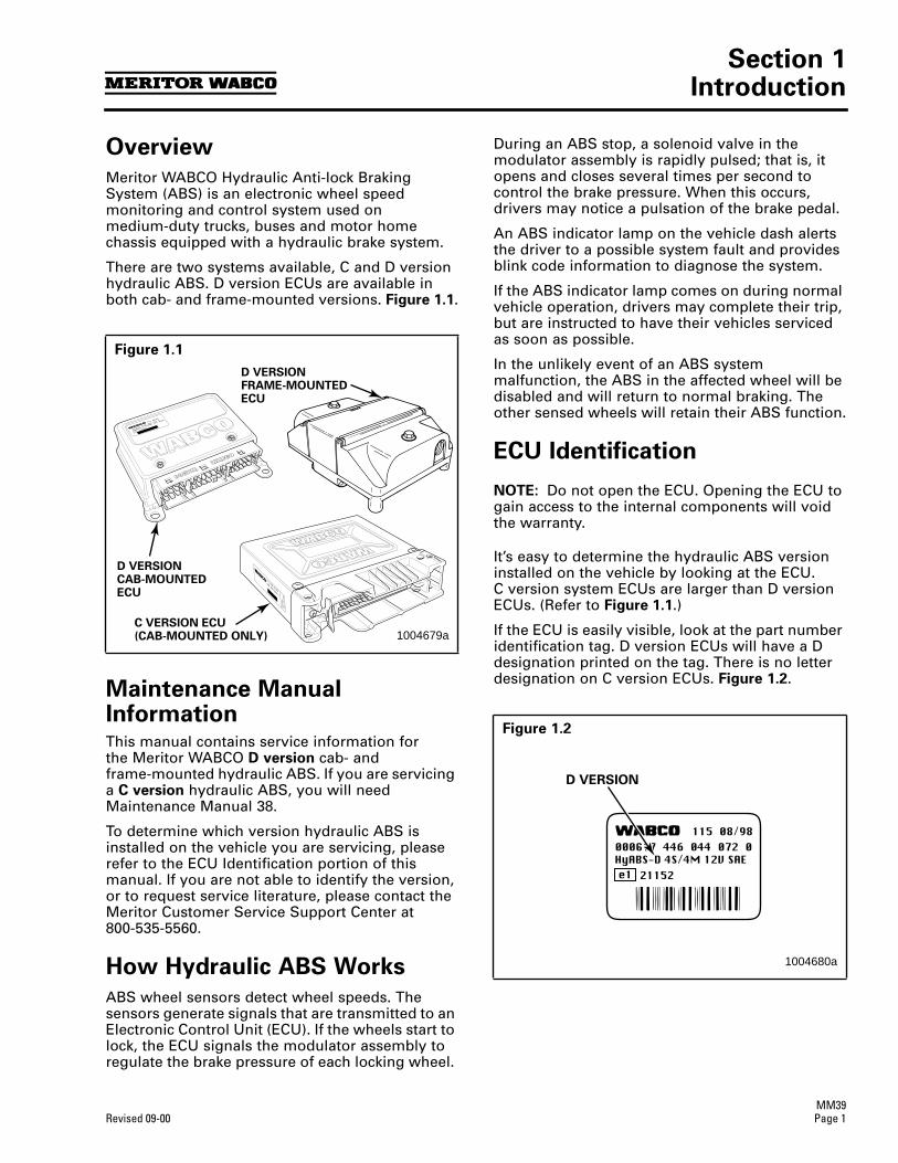
Section 1Introduction
MM39Revised 09-00 Page 1
Section 1Introduction
Overview
Meritor WABCO Hydraulic Anti-lock Braking System (ABS) is an electronic wheel speed monitoring and control system used on medium-duty trucks, buses and motor home chassis equipped with a hydraulic brake system.
There are two systems available, C and D version hydraulic ABS. D version ECUs are available in both cab- and frame-mounted versions.
Figure 1.1
.
Maintenance Manual Information
This manual contains service information forthe Meritor WABCO
D version
cab- andframe-mounted hydraulic ABS. If you are servicing a
C version
hydraulic ABS, you will need Maintenance Manual 38.
To determine which version hydraulic ABS is installed on the vehicle you are servicing, please refer to the ECU Identification portion of this manual. If you are not able to identify the version, or to request service literature, please contact the Meritor Customer Service Support Center at 800-535-5560.
How Hydraulic ABS Works
ABS wheel sensors detect wheel speeds. The sensors generate signals that are transmitted to an Electronic Control Unit (ECU). If the wheels start to lock, the ECU signals the modulator assembly to regulate the brake pressure of each locking wheel.
During an ABS stop, a solenoid valve in the modulator assembly is rapidly pulsed; that is, it opens and closes several times per second to control the brake pressure. When this occurs, drivers may notice a pulsation of the brake pedal.
An ABS indicator lamp on the vehicle dash alerts the driver to a possible system fault and provides blink code information to diagnose the system.
If the ABS indicator lamp comes on during normal vehicle operation, drivers may complete their trip, but are instructed to have their vehicles serviced as soon as possible.
In the unlikely event of an ABS system malfunction, the ABS in the affected wheel will be disabled and will return to normal braking. The other sensed wheels will retain their ABS function.
ECU Identification
NOTE:
Do not open the ECU. Opening the ECU to gain access to the internal components will void the warranty.
It’s easy to determine the hydraulic ABS version installed on the vehicle by looking at the ECU.C version system ECUs are larger than D version ECUs. (Refer to
Figure 1.1
.)
If the ECU is easily visible, look at the part number identification tag. D version ECUs will have a D designation printed on the tag. There is no letter designation on C version ECUs.
Figure 1.2
.
Figure 1.1
D VERSIONCAB-MOUNTEDECU
C VERSION ECU(CAB-MOUNTED ONLY)
D VERSIONFRAME-MOUNTEDECU
1004679a
Figure 1.2
D VERSION
1004680a
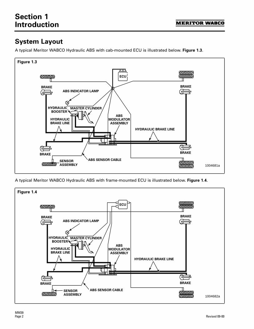
Section 1Introduction
MM39
Page 2
Revised 09-00
System Layout
A typical Meritor WABCO Hydraulic ABS with cab-mounted ECU is illustrated below.
Figure 1.3
.
A typical Meritor WABCO Hydraulic ABS with frame-mounted ECU is illustrated below.
Figure 1.4
.
Figure 1.3
Figure 1.4
ABS SENSOR CABLE
MASTER CYLINDER
ABS INDICATOR LAMP
ECU
SENSORASSEMBLY
HYDRAULICBRAKE LINE
ABSMODULATORASSEMBLY
BRAKE
BRAKE
BRAKE
BRAKE
HYDRAULIC BRAKE LINE
HYDRAULICBOOSTER
1004681a
ABS SENSOR CABLE
MASTER CYLINDER
ABS INDICATOR LAMP
ECU
SENSORASSEMBLY
HYDRAULICBRAKE LINE
ABSMODULATORASSEMBLY
BRAKE
BRAKE
BRAKE
BRAKE
HYDRAULIC BRAKE LINE
HYDRAULICBOOSTER
1004682a
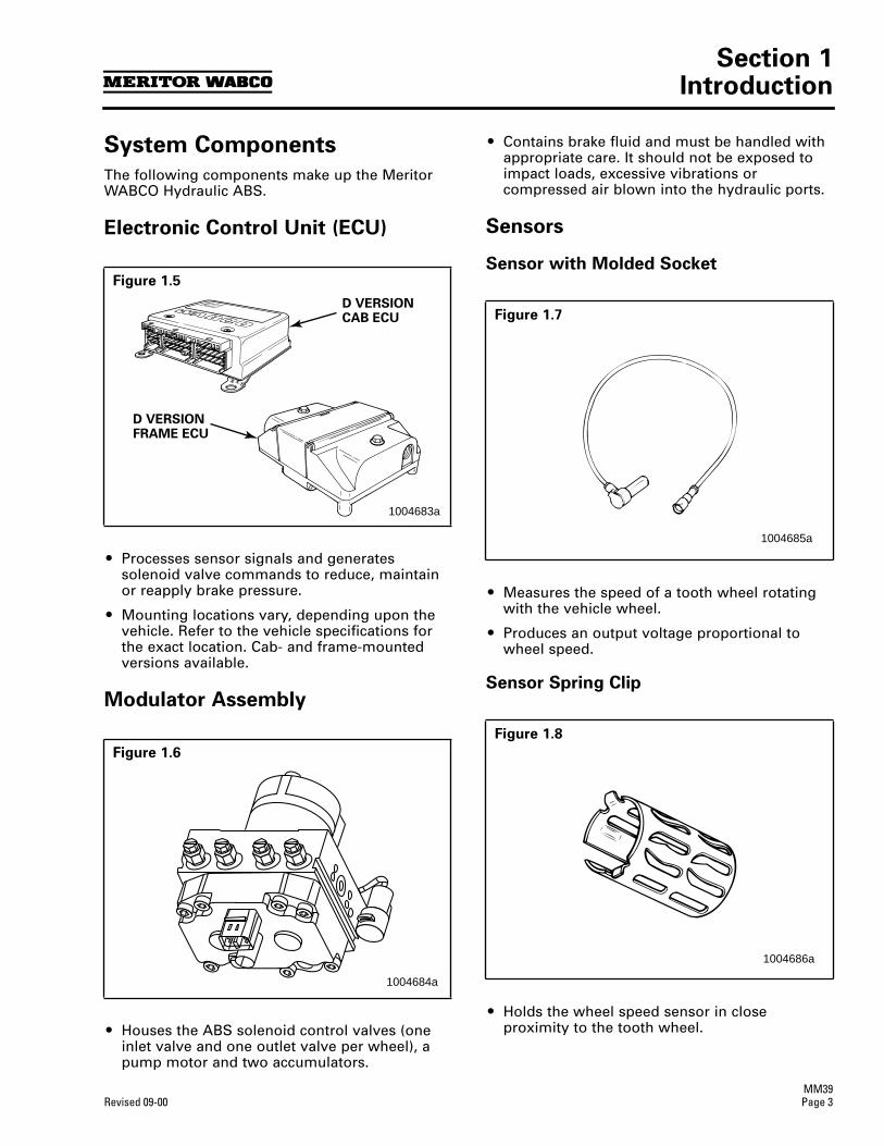
Section 1Introduction
MM39Revised 09-00 Page 3
System Components
The following components make up the Meritor WABCO Hydraulic ABS.
Electronic Control Unit (ECU)
r
Processes sensor signals and generates solenoid valve commands to reduce, maintain or reapply brake pressure.
r
Mounting locations vary, depending upon the vehicle. Refer to the vehicle specifications for the exact location. Cab- and frame-mounted versions available.
Modulator Assembly
r
Houses the ABS solenoid control valves (one inlet valve and one outlet valve per wheel), a pump motor and two accumulators.
r
Contains brake fluid and must be handled with appropriate care. It should not be exposed to impact loads, excessive vibrations or compressed air blown into the hydraulic ports.
Sensors
Sensor with Molded Socket
r
Measures the speed of a tooth wheel rotating with the vehicle wheel.
r
Produces an output voltage proportional to wheel speed.
Sensor Spring Clip
r
Holds the wheel speed sensor in close proximity to the tooth wheel.
Figure 1.5
Figure 1.6
D VERSIONFRAME ECU
D VERSIONCAB ECU
1004683a
1004684a
Figure 1.7
Figure 1.8
1004685a
1004686a
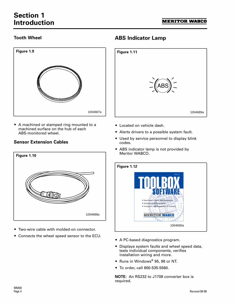
Section 1Introduction
MM39
Page 4
Revised 09-00
Tooth Wheel
r
A machined or stamped ring mounted to a machined surface on the hub of each ABS-monitored wheel.
Sensor Extension Cables
r
Two-wire cable with molded-on connector.
r
Connects the wheel speed sensor to the ECU.
ABS Indicator Lamp
r
Located on vehicle dash.
r
Alerts drivers to a possible system fault.
r
Used by service personnel to display blink codes.
r
ABS indicator lamp is not provided by Meritor WABCO.
r
A PC-based diagnostics program.
r
Displays system faults and wheel speed data, tests individual components, verifies installation wiring and more.
r
Runs in Windows
®
95, 98 or NT.
r
To order, call 800-535-5560.
NOTE:
An RS232 to J1708 converter box is required.
Figure 1.9
Figure 1.10
1004687a
1004688a
Figure 1.11
Figure 1.12
1004689a
ME
RIT
OR WABCO
WH
A TY O U N E E D
T OK
NO
WTOOLBOXSOFTWARE
E Easy-StopTM Trailer ABS Diagnostics
E Hydraulic ABS Diagnostics
E Pneumatic ABS Diagnostics (D Version)
TOOLBOXSOFTWARE
$98.00
1004690a
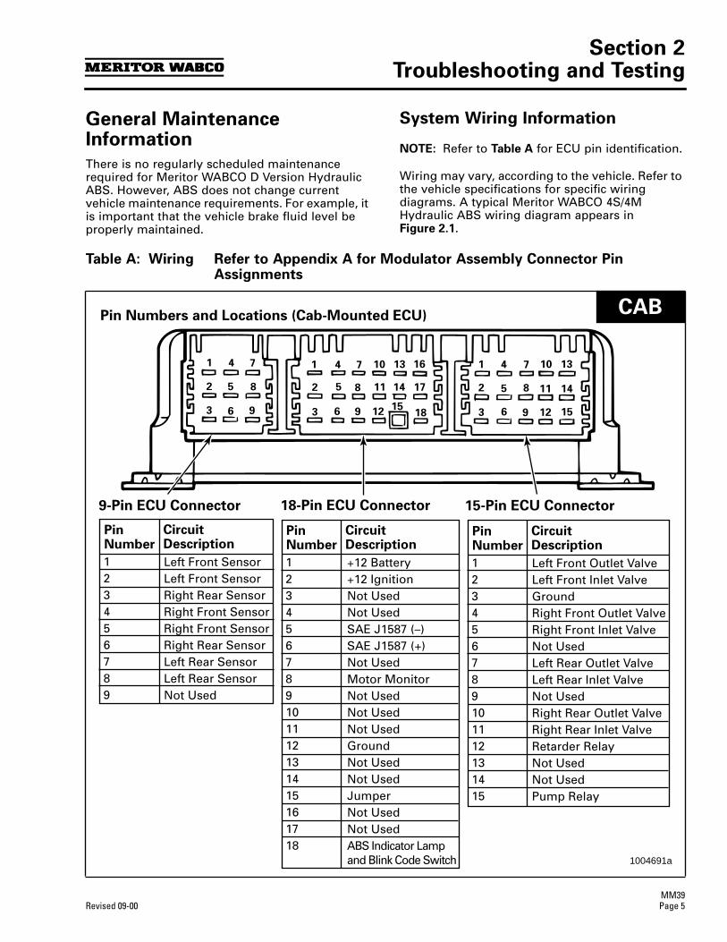
Section 2Troubleshooting and Testing
MM39Revised 09-00 Page 5
Section 2Troubleshooting and Testing
General Maintenance Information
There is no regularly scheduled maintenance required for Meritor WABCO D Version Hydraulic ABS. However, ABS does not change current vehicle maintenance requirements. For example, it is important that the vehicle brake fluid level be properly maintained.
System Wiring Information
NOTE:
Refer to
Table A
for ECU pin identification.
Wiring may vary, according to the vehicle. Refer to the vehicle specifications for specific wiring diagrams. A typical Meritor WABCO 4S/4M Hydraulic ABS wiring diagram appears in
Figure 2.1
.
Table A: Wiring Refer to Appendix A for Modulator Assembly Connector Pin Assignments
16
17
18
13
14
15
10
11
12
7
8
9
4
5
6
1
2
3
13
14
15
10
11
12
7
8
9
4
5
6
1
2
3
7
8
9
4
5
6
1
2
3
PinNumber
123456789
Left Front SensorLeft Front SensorRight Rear SensorRight Front SensorRight Front SensorRight Rear SensorLeft Rear SensorLeft Rear SensorNot Used
CircuitDescription
PinNumber
123456789101112131415161718
+12 Battery+12 IgnitionNot UsedNot UsedSAE J1587 (–)SAE J1587 (+)Not UsedMotor MonitorNot UsedNot UsedNot UsedGroundNot UsedNot UsedJumperNot UsedNot UsedABS Indicator Lampand Blink Code Switch
CircuitDescription
PinNumber
123456789101112131415
Left Front Outlet ValveLeft Front Inlet ValveGroundRight Front Outlet ValveRight Front Inlet ValveNot UsedLeft Rear Outlet ValveLeft Rear Inlet ValveNot UsedRight Rear Outlet ValveRight Rear Inlet ValveRetarder RelayNot UsedNot UsedPump Relay
CircuitDescription
9-Pin ECU Connector 18-Pin ECU Connector 15-Pin ECU Connector
Pin Numbers and Locations (Cab-Mounted ECU)
1004691a
CAB
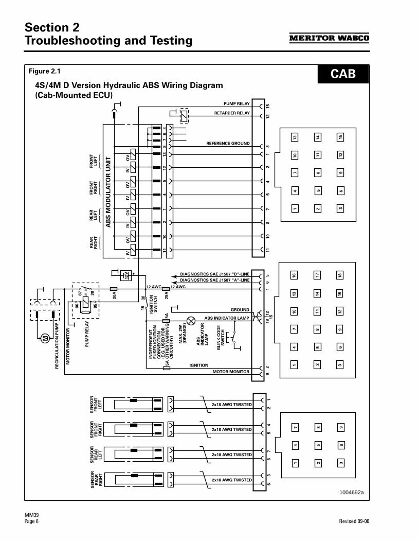
Section 2Troubleshooting and Testing
MM39
Page 6
Revised 09-00
Figure 2.1
16 17
18
13
14
15
10 11
12
7 8 9
4 5 6
1 2 3
13
14 15
10 11
12
7 8 9
4 5 6
1 2 3
7 8 9
4 5 6
1 2 3
2x18 AWG TWISTED
2x18 AWG TWISTED
2x18 AWG TWISTED
2x18 AWG TWISTED
SE
NS
OR
FR
ON
TLE
FT
SE
NS
OR
FR
ON
TR
IGH
T
SE
NS
OR
RE
AR
RIG
HT
SE
NS
OR
RE
AR
LE
FT
IVO
VIV
OV
IVO
VIV
OV
FR
ON
TLE
FT G
FR
ON
TR
IGH
T G
RE
AR
LE
FT G
RE
AR
RIG
HT G
AB
S M
OD
UL
AT
OR
UN
IT
REFERENCE GROUND
PUMP RELAY
RETARDER RELAY
RE
CIR
CU
LA
TIO
N P
UM
P
MO
TO
R M
ON
ITO
R
PU
MP
RE
LA
Y
30
87
85
86
30A
12V
– +
25A
30
15
IGN
ITIO
NS
WIT
CH
5A
IND
EP
EN
DE
NT
FU
SE
D IG
NIT
ION
CO
NN
EC
TIO
N(E
.G. U
SE
D F
OR
OT
HE
R W
AR
NIN
GC
IRC
UIT
RY
)
M
MA
X. 2W
(OR
AN
GE
)
AB
SIN
DIC
AT
OR
LA
MP
BLIN
K C
OD
ES
WIT
CH
5A
MOTOR MONITOR
ABS INDICATOR LAMP
GROUND
DIAGNOSTICS SAE J1587 “B”-LINE
DIAGNOSTICS SAE J1587 “A”-LINE
12 AWG 12 AWG
8 2
18 1
2 1 6 5
11 10 8
7 5
4
2
1
3
12
1
56 3 8 7
5 4
2
1
11 10 2 1
4
5
12
13
8
7
6
3
4S/4M D Version Hydraulic ABS Wiring Diagram
(Cab-Mounted ECU)
15
IGNITION
1004692a
CAB

Section 2Troubleshooting and Testing
MM39Revised 09-00 Page 7
Table B: Wiring Refer to Appendix A for Modulator Assembly Connector Pin Assignments
PinNumber
12345678
9101112
SAE J1587 (–)+12 Ignition+12 BatteryWarning Lamp RelayXPump RelayRetarder RelayABS Indicator Lampand Blink Code SwitchGroundMotor Monitor+12 BatterySAE J1587 (+)
CircuitDescription
PinNumber
123456789101112
XGroundLeft Front Inlet ValveRight Front Inlet ValveLeft Rear Inlet ValveRight Rear Inlet ValveRight Rear Outlet ValveLeft Rear Outlet ValveRight Front Outlet ValveLeft Front Outlet ValveXX
CircuitDescription
PinNumber
123456789101112
XXLeft Rear SensorRight Front SensorLeft Front SensorRight Rear SensorRight Rear SensorLeft Front SensorRight Front SensorLeft Rear SensorXX
CircuitDescription
Black X-2 Connector Gray X-1 Connector Green X-3 Connector
1004693a
Pin Numbers and Locations (Frame-Mounted ECU)
FRAME
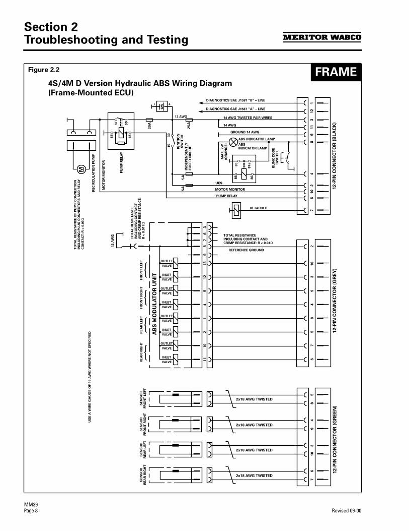
Section 2Troubleshooting and Testing
MM39
Page 8
Revised 09-00
Figure 2.2
12
-PIN
CO
NN
EC
TO
R (
BL
AC
K)
12
-PIN
CO
NN
EC
TO
R (
GR
EY
)1
2-P
IN C
ON
NE
CT
OR
(G
RE
EN
)
14
210
67
89
11
312
210
39
48
57
65
84
93
10
67
36
78
913
12
54
12
10
11
SE
NS
OR
FR
ON
T L
EFT
SE
NS
OR
FR
ON
T R
IGH
TS
EN
SO
RR
EA
R L
EFT
SE
NS
OR
RE
AR
RIG
HT
INLET
VALVE
5A
5A
25A
30A
UES
MA
X.
2W
(OR
AN
GE
)
IGN
ITIO
NS
WIT
CH
RETARDER
ABSINDICATOR LAMP
GROUND 14 AWG
PUMP RELAY
MOTOR MONITOR
ABS INDICATOR LAMP
IND
EP
EN
DE
NT
LY
F
US
ED
CIR
CU
IT
PU
MP
RE
LA
Y
MO
TO
R M
ON
ITO
R
RE
CIR
CU
LA
TIO
N P
UM
P
12V
FR
ON
T L
EFT
FR
ON
T R
IGH
TR
EA
R L
EFT
RE
AR
RIG
HT
DIAGNOSTICS SAE J1587 “B” – LINE
DIAGNOSTICS SAE J1587 “A” – LINE
TOTAL RESISTANCE INCLUDING CONTACT AND CRIMP RESISTANCE: R < 0.04Ω
TO
TA
L R
ES
ISTA
NC
E
INC
LU
DIN
G C
ON
TA
CT
A
ND
CR
IMP
RE
SIS
TA
NC
E:
R <
0.0
17
Ω
30
87
85
86 30
15
M
14 AWG TWISTED PAIR WIRES
14 AWG
12 AWG
86
85
87
a
30
+
AB
S M
OD
ULA
TO
R U
NIT
TO
TA
L R
ES
ISTA
NC
E O
F P
UM
P C
ON
NE
CT
ION
INC
LU
DIN
G P
LU
G C
ON
NE
CT
OR
S A
ND
RE
LA
Y
CO
NTA
CT: R
< 0
.03Ω
US
E A
WIR
E G
AU
GE
OF 1
6 A
WG
WH
ER
E N
OT
SP
EC
IFIE
D.
2x18 AWG TWISTED
2x18 AWG TWISTED
2x18 AWG TWISTED
2x18 AWG TWISTED
REFERENCE GROUND
OUTLET
VALVE
INLET
VALVE
OUTLET
VALVE
INLET
VALVE
OUTLET
VALVE
INLET
VALVE
OUTLET
VALVE
4S/4M D Version Hydraulic ABS Wiring Diagram
(Frame-Mounted ECU)
12 A
WG
BL
INK
CO
DE
SW
ITC
H
FRAME

Section 2Troubleshooting and Testing
MM39Revised 09-00 Page 9
System Diagnostics
Use Meritor WABCO’s PC-based diagnostic program, TOOLBOX Software, or standard blink codes to diagnose hydraulic ABS faults. Information for using standard blink codes appears on page 11 of this manual.
Meritor WABCOTOOLBOX Software
NOTE:
For complete instructions for using this program, refer to the User’s Manual, TP-99102. Contact Meritor WABCO at 800-535-5560 for information about TOOLBOX Software.
If you have TOOLBOX Software installed on your computer, use it to identify system faults. Then, follow the on-screen repair information to make the necessary repairs or replacements.
To display D version Hydraulic ABS faults, use the pull-down menu or the HABS icon
Figure 2.3
to select HABS (Hydraulic ABS) from the
Main Menu
. The
Hydraulic ABS Main Menu
will appear.
Figure 2.4
.
Select the View ECU Faults icon or select Display Faults to use the pull-down menu.
Figure 2.5
. This will display the
Fault Information
screen.
Figure 2.6
.
Figure 2.3
Figure 2.4
Figure 2.5
Figure 2.6
1004696a
1004697a
1004698a
Section 2Troubleshooting and Testing
MM39Page 10 Revised 09-00
The Fault Information Screen contains adescription of the fault. Repair instructions foreach fault appear at the bottom of the screen.
Faults that occur after the screen is displayed willnot appear until a screen update is requested. Usethe UPDATE button to refresh the fault informationtable.After making the necessary repairs, use the CLEARFAULTS button to clear the fault. Use the updatebutton to refresh the fault information table anddisplay the new list of faults.
Blink Code Diagnostics
DefinitionsABS Indicator Lamp: This lamp, located on thevehicle dash, serves two purposes:
1. Alerts drivers or service personnel to apossible fault in the hydraulic ABS, as follows:
IF . . .the ABS indicator lamp comes on brießythen goes OFF when the ignition isturned ON . . . . . there are no active orstored faults in the hydraulic ABS
IF . . .the ABS indicator lamp comes on andstays on AFTER the ignition is turned ON
andThe vehicle is driven in excessof 4 mph (6 km/h) . . . There may bean active fault in the hydraulic ABS
IF . . .ABS indicator lamp comes on andstays on
andGoes OFF after the vehicle is driven inexcess of 4 mph (6 km/h) . . .
Theremay be a stored fault in thehydraulic ABS
2. Displays diagnostic blink codes foreasy servicing.
Blink Code: A series of blinks or ?ashes thatdescribe a particular ABS system condition.(Refer to Table D [cab-mounted] or Table E[frame-mounted] for blink code identiÞcation.)
**Blink Code Diagnostics: The ability of the MeritorWABCO ECU to sense faults in the ABS systemand to deÞne these faults via blink codes.
Blink Code Switch: A momentary switch thatactivates blink code diagnostic capabilities.Usually, it is mounted under the dash or on thesteering column. Refer to the vehiclespeciÞcations for type and location.
Clearing Fault Codes: The process of erasing faultsfrom the ECU memory bank. (Refer to Table C.)
Fault Code: An ABS condition (fault) detected andstored in memory by the Meritor WABCO ECU anddisplayed by blink code. System faults may beActive or Stored .
Active Fault: A condition that currently existsin the ABS system; for example, a sensorcircuit malfunction on the left front steeringaxle. An active fault must be repaired beforeyou can display additional faults. Once anactive fault has been repaired, it becomes astored fault.
Stored Fault: A condition that caused thesystem to register a fault, but is not currentlyactive. For example, a loose wire thatcorrected itself. A stored fault can also be anactive fault that has been corrected (refer toActive Fault).
Table C describes the method of distinguishingbetween active and stored faults and explainshow to clear them.
5
5
The Tech 2 cannot access the Meritor Wabco® ABS module. Diagnosis can beaccomplished using the Toolbox® software connected to a PC using the appropriateadapters and cables.
Diagnostic “blink codes” can be retrieved using the procedure described on the followingpages of this section. Workhorse chassis are not equipped with a Blink Code switch.To access the fault codes perform the following steps:
• Locate Pin 8 of the Black X-2 Connector at the ABS ECU• Backprobe the circuit at the connector with a jumper wire• Ground the other end of the jumper wire for 1 second and them remove• The ABS should begin to flash the stored code(s) in memory
** NOTE:
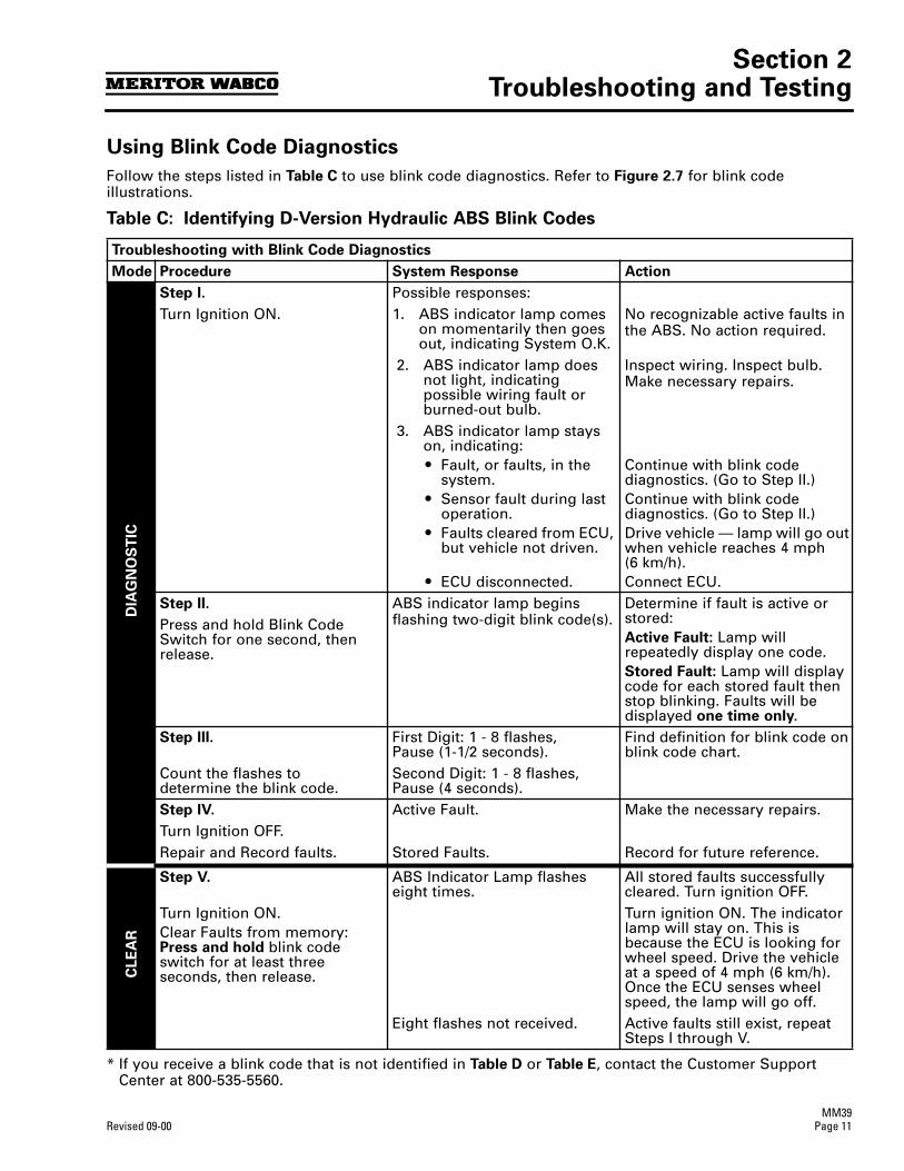
Section 2Troubleshooting and Testing
MM39Revised 09-00 Page 11
Using Blink Code Diagnostics
Follow the steps listed in Table C to use blink code diagnostics. Refer to Figure 2.7 for blink code illustrations.
Table C: Identifying D-Version Hydraulic ABS Blink Codes
* If you receive a blink code that is not identified in Table D or Table E, contact the Customer Support Center at 800-535-5560.
Troubleshooting with Blink Code Diagnostics
Mode Procedure System Response Action
DIA
GN
OS
TIC
Step I. Possible responses:Turn Ignition ON. 1. ABS indicator lamp comes
on momentarily then goes out, indicating System O.K.
No recognizable active faults in the ABS. No action required.
2. ABS indicator lamp does not light, indicating possible wiring fault or burned-out bulb.
Inspect wiring. Inspect bulb.Make necessary repairs.
3. ABS indicator lamp stays on, indicating:r Fault, or faults, in the
system.r Sensor fault during last
operation.r Faults cleared from ECU,
but vehicle not driven.
r ECU disconnected.
Continue with blink code diagnostics. (Go to Step II.)Continue with blink code diagnostics. (Go to Step II.)Drive vehicle — lamp will go out when vehicle reaches 4 mph (6 km/h).Connect ECU.
Step II. ABS indicator lamp begins flashing two-digit blink code(s).
Determine if fault is active or stored:Active Fault: Lamp will repeatedly display one code. Stored Fault: Lamp will display code for each stored fault then stop blinking. Faults will be displayed one time only.
Press and hold Blink Code Switch for one second, then release.
Step III. First Digit: 1 - 8 flashes,Pause (1-1/2 seconds).
Find definition for blink code on blink code chart.
Count the flashes to determine the blink code.
Second Digit: 1 - 8 flashes,Pause (4 seconds).
Step IV. Active Fault. Make the necessary repairs. Turn Ignition OFF.Repair and Record faults. Stored Faults. Record for future reference.
CLE
AR
Step V. ABS Indicator Lamp flashes eight times.
All stored faults successfully cleared. Turn ignition OFF.
Turn Ignition ON.Clear Faults from memory: Press and hold blink code switch for at least three seconds, then release.
Turn ignition ON. The indicator lamp will stay on. This is because the ECU is looking for wheel speed. Drive the vehicle at a speed of 4 mph (6 km/h). Once the ECU senses wheel speed, the lamp will go off.
Eight flashes not received. Active faults still exist, repeat Steps I through V.

Section 2Troubleshooting and Testing
MM39Page 12 Revised 09-00
Using Blink Code Diagnostics, Continued
Blink Codes Illustrated
Figure 2.7
Pause1.5 s
Pause1.5 s
1-8 Flashes
Pause1.5 s
Pause4 s
1-6 Flashes
Light ON
Active Fault
Pause1.5 s
Pause1.5 s
Light ON
1 SecondHold
1 SecondHold
System O.K.
Continues untilignition is turned off
1st Digit
(2) (3) (2) (3)
(5)
(1) (1)
(2) (3) (4)
2nd Digit
Pause1.5 s
Pause1.5 s
Pause1.5 s
Pause4 s
Light ON
Off
Stored Faults
S = Seconds
Displays all storedfaults once – last faultstored is displayed first
Blink Code 2-3: Fault in ABS modulatorvalve, right rear drive axle.
Blink Code 5-2: Sensor signal erratic,left front steer axle.
3-4: Too much sensor gap,left rear drive axle.
Blink Code 1-1: System OK
1st Digit 2nd Digit 1st Digit 2nd Digit1st Stored Fault 2nd Stored Fault
Repeat of Blink Code
1 SecondHold
1002021b

Section 2Troubleshooting and Testing
MM39Revised 09-00 Page 13
Using Blink Code Diagnostics, Continued
Pause1.5 s
Pause4 s
Pause4 s
Light ON
Faults Cleared
Pause4 s
Pause4 s
Pause4 s
Pause4 s
Light ON
Faults Not Cleared (Active Faults Still Exist)3 Second
Hold
3 SecondHold
Continuesuntil ignitionis turned off
Note: After faults are cleared andvehicle is started, ABS lamp will stayon until vehicle is driven over 4 mph (6 km/h).
Continuesuntil ignitionis turned off
8 Quick Blinks = Faults Cleared
(2)
SystemStatus
Pause4 s
Pause4 s
Code 2
1002022aS = Seconds
(2)
SystemStatus
(2)
SystemStatus
(2)
SystemStatus
(2)
SystemStatus
(2)
SystemStatus
(2)
SystemStatus
(2)
SystemStatus
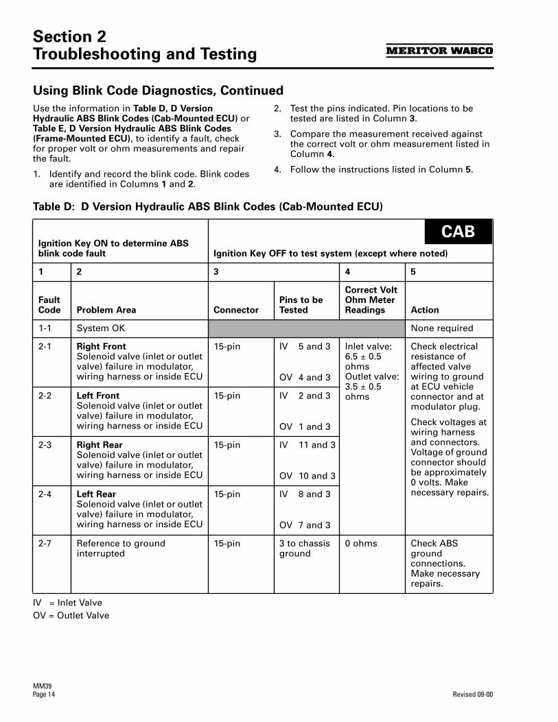
Section 2Troubleshooting and Testing
MM39Page 14 Revised 09-00
Using Blink Code Diagnostics, Continued
Use the information in Table D, D Version Hydraulic ABS Blink Codes (Cab-Mounted ECU) or Table E, D Version Hydraulic ABS Blink Codes (Frame-Mounted ECU), to identify a fault, check for proper volt or ohm measurements and repair the fault.
1. Identify and record the blink code. Blink codes are identified in Columns 1 and 2.
2. Test the pins indicated. Pin locations to be tested are listed in Column 3.
3. Compare the measurement received against the correct volt or ohm measurement listed in Column 4.
4. Follow the instructions listed in Column 5.
Table D: D Version Hydraulic ABS Blink Codes (Cab-Mounted ECU)
IV = Inlet ValveOV = Outlet Valve
Ignition Key ON to determine ABS blink code fault Ignition Key OFF to test system (except where noted)
1 2 3 4 5
Fault Code Problem Area Connector
Pins to be Tested
Correct Volt Ohm Meter Readings Action
1-1 System OK None required
2-1 Right Front Solenoid valve (inlet or outlet valve) failure in modulator, wiring harness or inside ECU
15-pin IV 5 and 3
OV 4 and 3
Inlet valve: 6.5 ± 0.5 ohms Outlet valve: 3.5 ± 0.5 ohms
Check electrical resistance of affected valve wiring to ground at ECU vehicle connector and at modulator plug.
Check voltages at wiring harness and connectors. Voltage of ground connector should be approximately 0 volts. Make necessary repairs.
2-2 Left Front Solenoid valve (inlet or outlet valve) failure in modulator, wiring harness or inside ECU
15-pin IV 2 and 3
OV 1 and 3
2-3 Right Rear Solenoid valve (inlet or outlet valve) failure in modulator, wiring harness or inside ECU
15-pin IV 11 and 3
OV 10 and 3
2-4 Left Rear Solenoid valve (inlet or outlet valve) failure in modulator, wiring harness or inside ECU
15-pin IV 8 and 3
OV 7 and 3
2-7 Reference to ground interrupted
15-pin 3 to chassis ground
0 ohms Check ABS ground connections. Make necessary repairs.
CAB

Section 2Troubleshooting and Testing
MM39Revised 09-00 Page 15
Using Blink Code Diagnostics, Continued
Table D: D Version Hydraulic ABS Blink Codes (Cab-Mounted ECU), Continued
Ignition Key ON to determine ABS blink code fault Ignition Key OFF to test system (except where noted)
1 2 3 4 5
Fault Code Problem Area Connector
Pins to be Tested
Correct Volt Ohm Meter Readings Action
3-1 Right Frontsensor — Air gap
9-pin 4 and 5 Greater than .2 volts AC at 30 RPM
(Rotate wheel 1/2 revolution per second)
Check for sensor adjustment. Check for excessive wheel bearing endplay. Repair or replace as needed.
3-2 Left Frontsensor — Air gap
9-pin 1 and 2
3-3 Right Rearsensor —- Air gap
9-pin 3 and 6
3-4 Left Rearsensor — Air gap
9-pin 7 and 8
4-1 Right Frontsensor — Electrical fault
9-pin 4 and 5 900-2000 ohms
Check electrical resistance of affected sensor and wiring at ECU connector and at harness plugs. Repair or replace as needed.
4-2 Left Frontsensor — Electrical fault
9-pin 1 and 2
4-3 Right Rearsensor — Electrical fault
9-pin 3 and 6
4-4 Left Rearsensor — Electrical fault
9-pin 7 and 8
5-1 Right Frontwheel — Erratic wheel speed
Check for tire size mismatch or tooth wheel difference. Check sensor, sensor cable and connector for intermittent contact. Repair or replace as needed.
5-2 Left Frontwheel — Erratic wheel speed
5-3 Right Rearwheel — Erratic wheel speed
5-4 Left Rearwheel — Erratic wheel speed
7-3 Retarder Relay 15-pin 12 to chassis ground
50-200 ohms Verify proper connections to relay. (Refer to wiring diagram.)
7-4 ABS warning lamp 18-pin 18 and 2 10-200 ohms Check bulb. Repair or replace as needed.
CAB
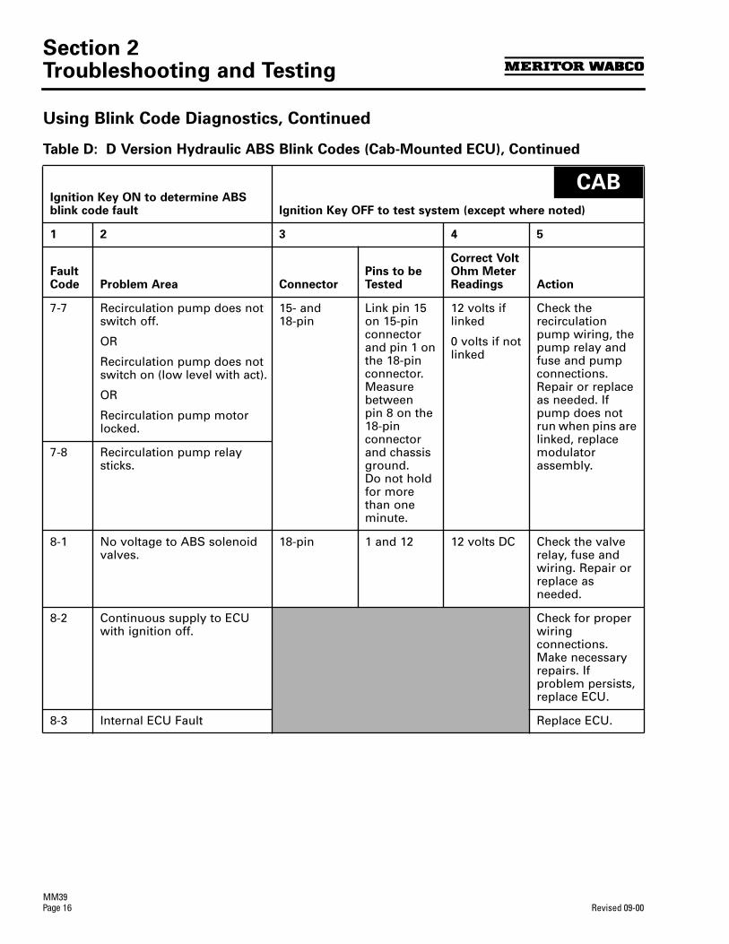
Section 2Troubleshooting and Testing
MM39Page 16 Revised 09-00
Using Blink Code Diagnostics, Continued
Table D: D Version Hydraulic ABS Blink Codes (Cab-Mounted ECU), Continued
Ignition Key ON to determine ABS blink code fault Ignition Key OFF to test system (except where noted)
1 2 3 4 5
Fault Code Problem Area Connector
Pins to be Tested
Correct Volt Ohm Meter Readings Action
7-7 Recirculation pump does not switch off.
OR
Recirculation pump does not switch on (low level with act).
OR
Recirculation pump motor locked.
15- and 18-pin
Link pin 15 on 15-pin connector and pin 1 on the 18-pin connector.Measure betweenpin 8 on the18-pin connector and chassis ground.Do not hold for more than one minute.
12 volts if linked
0 volts if not linked
Check the recirculation pump wiring, the pump relay and fuse and pump connections. Repair or replace as needed. If pump does not run when pins are linked, replace modulator assembly.
7-8 Recirculation pump relay sticks.
8-1 No voltage to ABS solenoid valves.
18-pin 1 and 12 12 volts DC Check the valve relay, fuse and wiring. Repair or replace as needed.
8-2 Continuous supply to ECU with ignition off.
Check for proper wiring connections. Make necessary repairs. If problem persists, replace ECU.
8-3 Internal ECU Fault Replace ECU.
CAB
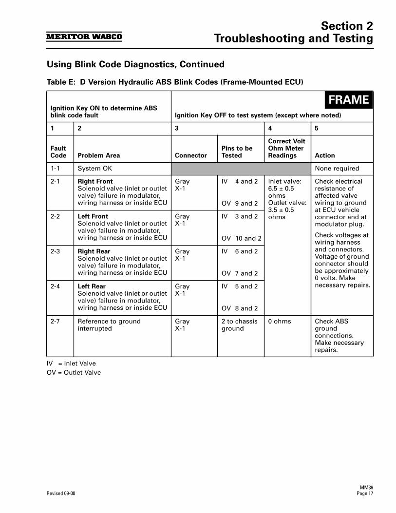
Section 2Troubleshooting and Testing
MM39Revised 09-00 Page 17
Using Blink Code Diagnostics, Continued
Table E: D Version Hydraulic ABS Blink Codes (Frame-Mounted ECU)
IV = Inlet ValveOV = Outlet Valve
Ignition Key ON to determine ABS blink code fault Ignition Key OFF to test system (except where noted)
1 2 3 4 5
Fault Code Problem Area Connector
Pins to be Tested
Correct Volt Ohm Meter Readings Action
1-1 System OK None required
2-1 Right Front Solenoid valve (inlet or outlet valve) failure in modulator, wiring harness or inside ECU
GrayX-1
IV 4 and 2
OV 9 and 2
Inlet valve: 6.5 ± 0.5 ohms Outlet valve: 3.5 ± 0.5 ohms
Check electrical resistance of affected valve wiring to ground at ECU vehicle connector and at modulator plug.
Check voltages at wiring harness and connectors. Voltage of ground connector should be approximately 0 volts. Make necessary repairs.
2-2 Left Front Solenoid valve (inlet or outlet valve) failure in modulator, wiring harness or inside ECU
GrayX-1
IV 3 and 2
OV 10 and 2
2-3 Right Rear Solenoid valve (inlet or outlet valve) failure in modulator, wiring harness or inside ECU
GrayX-1
IV 6 and 2
OV 7 and 2
2-4 Left Rear Solenoid valve (inlet or outlet valve) failure in modulator, wiring harness or inside ECU
GrayX-1
IV 5 and 2
OV 8 and 2
2-7 Reference to ground interrupted
GrayX-1
2 to chassis ground
0 ohms Check ABS ground connections. Make necessary repairs.
FRAME
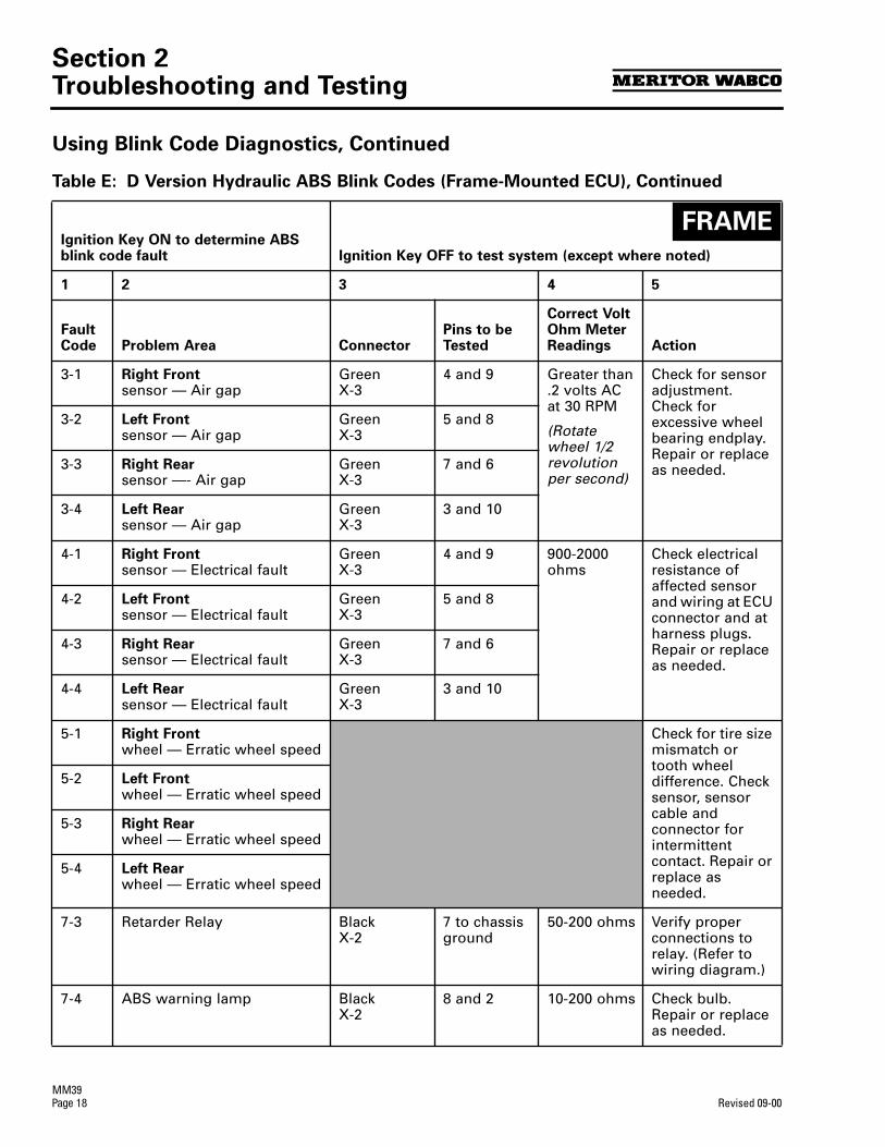
Section 2Troubleshooting and Testing
MM39Page 18 Revised 09-00
Using Blink Code Diagnostics, Continued
Table E: D Version Hydraulic ABS Blink Codes (Frame-Mounted ECU), Continued
Ignition Key ON to determine ABS blink code fault Ignition Key OFF to test system (except where noted)
1 2 3 4 5
Fault Code Problem Area Connector
Pins to be Tested
Correct Volt Ohm Meter Readings Action
3-1 Right Frontsensor — Air gap
GreenX-3
4 and 9 Greater than .2 volts AC at 30 RPM
(Rotate wheel 1/2 revolution per second)
Check for sensor adjustment. Check for excessive wheel bearing endplay. Repair or replace as needed.
3-2 Left Frontsensor — Air gap
GreenX-3
5 and 8
3-3 Right Rearsensor —- Air gap
GreenX-3
7 and 6
3-4 Left Rearsensor — Air gap
GreenX-3
3 and 10
4-1 Right Frontsensor — Electrical fault
GreenX-3
4 and 9 900-2000 ohms
Check electrical resistance of affected sensor and wiring at ECU connector and at harness plugs. Repair or replace as needed.
4-2 Left Frontsensor — Electrical fault
GreenX-3
5 and 8
4-3 Right Rearsensor — Electrical fault
GreenX-3
7 and 6
4-4 Left Rearsensor — Electrical fault
GreenX-3
3 and 10
5-1 Right Frontwheel — Erratic wheel speed
Check for tire size mismatch or tooth wheel difference. Check sensor, sensor cable and connector for intermittent contact. Repair or replace as needed.
5-2 Left Frontwheel — Erratic wheel speed
5-3 Right Rearwheel — Erratic wheel speed
5-4 Left Rearwheel — Erratic wheel speed
7-3 Retarder Relay Black X-2
7 to chassis ground
50-200 ohms Verify proper connections to relay. (Refer to wiring diagram.)
7-4 ABS warning lamp Black X-2
8 and 2 10-200 ohms Check bulb. Repair or replace as needed.
FRAME

Section 2Troubleshooting and Testing
MM39Revised 09-00 Page 19
Using Blink Code Diagnostics, Continued
Table E: D Version Hydraulic ABS Blink Codes (Frame-Mounted ECU), Continued
Ignition Key ON to determine ABS blink code fault Ignition Key OFF to test system (except where noted)
1 2 3 4 5
Fault Code Problem Area Connector
Pins to be Tested
Correct Volt Ohm Meter Readings Action
7-7 Recirculation pump does not switch off.
OR
Recirculation pump does not switch on (low level with act).
OR
Recirculation pump motor locked.
BlackX-2
Link pins 6 and 3.
Measure betweenpin 10 and chassis ground.
Do not hold for more than one minute.
12 volts if linked
0 volts if not linked
12 volts DC
Turn Ignition ON
Check the recirculation pump wiring, the pump relay and fuse and pump connections. Repair or replace as needed. If pump does not run when pins are linked, replace modulator assembly.
7-8 Recirculation pump relay sticks.
8-1 No voltage to ABS solenoid valves.
BlackX-2
3 and 9 12 volts DC Check the valve relay, fuse and wiring. Repair or replace as needed.
8-2 Continuous supply to ECU with ignition off.
Check for proper wiring connections. Make necessary repairs. If problem persists, replace ECU.
8-3 Internal ECU Fault Replace ECU.
FRAME

Section 2Troubleshooting and Testing
MM39Page 20 Revised 09-00
Testing the System
This section of the manual contains information for testing the hydraulic ABS with TOOLBOX Software, as well as procedures for conducting standard air and electrical tests.
WARNING
To prevent serious eye injury, always wear safe eye protection when you perform vehicle maintenance or service.
Exhaust gas contains poison. When testing a vehicle with the engine running, test in a well-ventilated area or route the exhaust hose outside.
To avoid serious personal injury, keep away, and keep test equipment away, from all moving or hot engine parts.
Refer to, and follow, the vehicle manufacturer’sWarnings, Cautions and Service Procedures.
When testing, set the parking brake and place the gear selector in NEUTRAL (manual transmission) or PARK (automatic transmission) unless otherwise directed.
Meritor WABCOTOOLBOX Software
Use TOOLBOX Software to verify the activation of various system components:
Turn valves, pump and retarder relay on and off (Valve Activation Menu). Turn ABS indicator lamp on and off (Miscellaneous Output Activation Menu). Reset components in ECU memory.
NOTE: For complete instructions for using this program, refer to the User’s Manual, TP-99102. Contact Meritor WABCO at 800-535-5560 for information about TOOLBOX Software.
Valve, Pump and Retarder Relay Activation
To activate the ABS valves, pump or retarder relay, select HABS (Hydraulic ABS) from the Main Menu. The Hydraulic ABS Main Menu will appear.Figure 2.8.
Select the Valve Activation icon or select Component Tests, then Valves to use thepull-down menu. Figure 2.9. This displays the Valve Activation screen. Figure 2.10.
Figure 2.8
Figure 2.9
Figure 2.10
1004696a
1004700a
1004701a
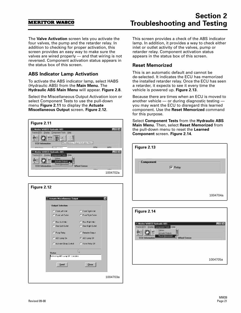
Section 2Troubleshooting and Testing
MM39Revised 09-00 Page 21
The Valve Activation screen lets you activate the four valves, the pump and the retarder relay. In addition to checking for proper activation, this screen provides an easy way to make sure the valves are wired properly — and that wiring is not reversed. Component activation status appears in the status box of this screen.
ABS Indicator Lamp Activation
To activate the ABS indicator lamp, select HABS (Hydraulic ABS) from the Main Menu. The Hydraulic ABS Main Menu will appear. Figure 2.8.
Select the Miscellaneous Output Activation icon or select Component Tests to use the pull-down menu Figure 2.11 to display the Actuate Miscellaneous Output screen. Figure 2.12.
This screen provides a check of the ABS indicator lamp. In addition, it provides a way to check either inlet or outlet activity of the valves, pump or retarder relay. Component activation status appears in the status box of this screen.
Reset Memorized
This is an automatic default and cannot bede-selected. It indicates the ECU has memorized the installed retarder relay. Once the ECU has seen a retarder, it expects to see it every time the vehicle is powered up. Figure 2.13.
Because there are times when an ECU is moved to another vehicle — or during diagnostic testing — you may want the ECU to disregard this learned component. Use the Reset Memorized command for this purpose.
Select Component Tests from the Hydraulic ABS Main Menu. Then, select Reset Memorized from the pull-down menu to reset the Learned Component screen. Figure 2.14.
Figure 2.11
Figure 2.12
1004702a
1004703a
Figure 2.13
Figure 2.14
1004704a
1004705a
Section 2Troubleshooting and Testing
MM39Page 22 Revised 09-00
Standard Testing
Test Equipment: Volt-Ohm Meter (VOM)
Use of a VOM with automatic polarity sensing is recommended. This eliminates the concernof the polarity of the meter leads during voltage measurements.
System Requirements and Component Tests
Tire Size Range
For proper hydraulic ABS operation, front and rear tire sizes must be within 16% of each other.
Contact the Meritor WABCO Customer Support Center at 800-535-5560 if you plan a tire size difference greater than ±8%.
Calculate the tire size with the following equation:
CAUTION
When troubleshooting or testing the ABS system, do not damage the connector terminals.
Voltage Check
Voltage must be between 9.5 and 14 volts for the 12-volt hydraulic ABS to function properly.
Check voltage as follows:
1. Turn ignition ON.
2. Check for proper voltage:
Cab-mounted ECU: Pins 12 and 1 and 12 and 2 on the 18-pin connector.
Frame-mounted ECU: Pins 9 and 3 and 9 and 2 on the black connector.
If voltage is not between 9.5 and 14 volts, verify proper wiring connections. Make corrections as required.
Standard Component Testing
ABS Indicator Lamp
If the ABS indicator lamp does not come on after the ignition is turned on, or it comes on but does not go out after three seconds, check all ABS fuses or circuit breakers and replace if necessary. Check the wiring to the ABS diagnostic switch and the indicator lamp and repair or replace the wiring as required. When checking the indicator lamp, follow these steps:
1. Check voltage potential at the lamp socket.
2. Check continuity of the wires to the socket.
3. Replace the bulb.
NOTE: A complete wiring diagram for 4S/4M D-version hydraulic ABS appears in Figure 2.1.
ABS Blink Code Switch
When testing the ABS Diagnostic switch:
1. Check the resistance between the terminals while cycling the switch. A lack of resistance is an indication of a faulty switch.
2. Check the continuity of the wires to the switch:
Cab-mounted ECU: Pins 18 and 12 on the18-pin connector.
Frame-mounted ECU: Pins 8 and 9 on the black connector.
Sensor Adjustment
On steering axles, the sensor is typically accessible on the in-board side of the steering knuckle.
On drive axles, the sensor is typically accessible on the in-board side of the rear axle spindle.
To adjust the sensor, push the sensor in until it contacts the tooth wheel:
r Do not pry or push sensors with sharp objects
r Sensors will self-adjust during wheel rotation.
NOTE: No gap is allowable at installation. During normal operation a gap not to exceed 0.04-inch is allowable.
% Difference = G RPM Steer H – 1 x 100RPM Drive
RPM = tire revolutions per mile
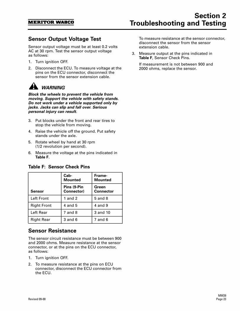
Section 2Troubleshooting and Testing
MM39Revised 09-00 Page 23
Sensor Output Voltage Test
Sensor output voltage must be at least 0.2 volts AC at 30 rpm. Test the sensor output voltage as follows:
1. Turn ignition OFF.
2. Disconnect the ECU. To measure voltage at the pins on the ECU connector, disconnect the sensor from the sensor extension cable.
WARNING
Block the wheels to prevent the vehicle from moving. Support the vehicle with safety stands. Do not work under a vehicle supported only by jacks. Jacks can slip and fall over. Serious personal injury can result.
3. Put blocks under the front and rear tires to stop the vehicle from moving.
4. Raise the vehicle off the ground. Put safety stands under the axle.
5. Rotate wheel by hand at 30 rpm (1/2 revolution per second).
6. Measure the voltage at the pins indicated in Table F.
Table F: Sensor Check Pins
Sensor Resistance
The sensor circuit resistance must be between 900 and 2000 ohms. Measure resistance at the sensor connector, or at the pins on the ECU connector, as follows:
1. Turn ignition OFF.
2. To measure resistance at the pins on ECU connector, disconnect the ECU connector from the ECU.
To measure resistance at the sensor connector, disconnect the sensor from the sensor extension cable.
3. Measure output at the pins indicated in Table F, Sensor Check Pins.
If measurement is not between 900 and 2000 ohms, replace the sensor.
Sensor
Cab-Mounted
Frame-Mounted
Pins (9-Pin Connector)
Green Connector
Left Front 1 and 2 5 and 8
Right Front 4 and 5 4 and 9
Left Rear 7 and 8 3 and 10
Right Rear 3 and 6 7 and 6

Notes
MM39Page 24 Revised 09-00

Section 3Component Replacement
MM39Revised 09-00 Page 25
Section 3Component ReplacementComponent Removal and Installation
Sensors
Sensor Lube Specification
Meritor WABCO specifications call for a sensor lubricant with the following characteristics:
Lube must be mineral oil-based and contain molydisulfide. It should have excellent anti-corrosion and adhesion characteristics and be capable of continuous function in a temperature range of –40˚ to 300˚F (–40˚ to 150˚C).
Wheel Speed Sensor Replacement — Front Axle
Removal
WARNING
To prevent serious eye injury, always wear safe eye protection when you perform vehicle maintenance or service.
Block the wheels to prevent the vehicle from moving. Support the vehicle with safety stands. Do not work under a vehicle supported only by jacks. Jacks can slip and fall over. Serious personal injury can result.
To avoid damage to the electrical system or ABS components, when welding on an ABS-equipped vehicle disconnect the power connector from the ECU.
1. Apply the parking brakes. Chock the rear tires to prevent vehicle movement.
If necessary, raise the front tires off the ground. Put safety stands under the axle.
2. Disconnect the fasteners that hold the sensor cable to other components.
3. Disconnect the sensor cable from the chassis harness.
4. Remove the sensor from the sensor holder. Twist and pull the sensor to remove it from the sensor bracket. Do not pull on the cable. Figure 3.1.
Installation
1. Connect the sensor cable to the chassis harness.
2. Install the fasteners used to hold the sensor cable in place.
3. Apply a Meritor WABCO-recommended lubricant to the sensor spring clip and sensor.
4. Install the sensor spring clip. Make sure the spring clip tabs are on the inboard side of the vehicle.
5. With the tabs on the inboard side, push the sensor spring clip into the bushing in the steering knuckle until the clip stops.
6. Push the sensor completely into the sensor spring clip until it contacts the tooth wheel.
7. Fasten the sensor cable with tie wraps every12 inches. Properly bundle and store excess cable in the sub frame. Figure 3.2.
8. Remove the blocks and safety stands.
9. Perform a voltage output check to ensure proper installation. Refer to “Sensor Output Voltage Test” in Section 2.
Figure 3.1
KNUCKLE-MOUNTEDSENSOR
1004706a
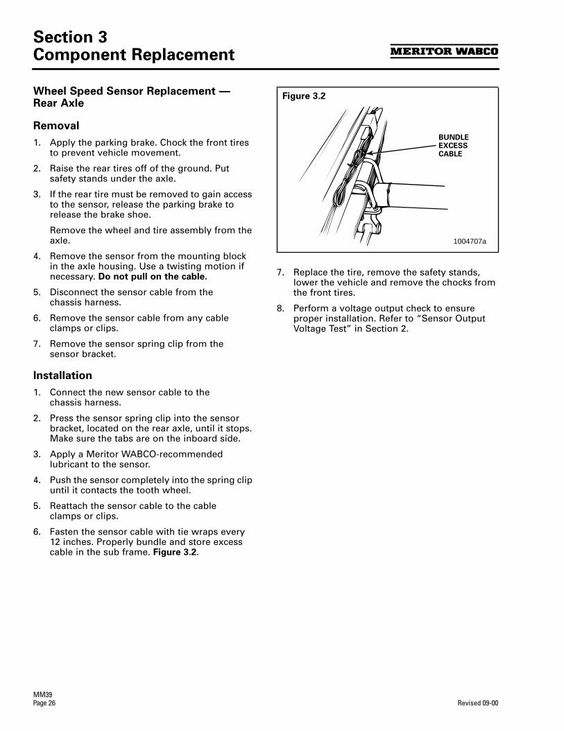
Section 3Component Replacement
MM39Page 26 Revised 09-00
Wheel Speed Sensor Replacement — Rear Axle
Removal
1. Apply the parking brake. Chock the front tires to prevent vehicle movement.
2. Raise the rear tires off of the ground. Put safety stands under the axle.
3. If the rear tire must be removed to gain access to the sensor, release the parking brake to release the brake shoe.
Remove the wheel and tire assembly from the axle.
4. Remove the sensor from the mounting block in the axle housing. Use a twisting motion if necessary. Do not pull on the cable.
5. Disconnect the sensor cable from the chassis harness.
6. Remove the sensor cable from any cable clamps or clips.
7. Remove the sensor spring clip from the sensor bracket.
Installation
1. Connect the new sensor cable to the chassis harness.
2. Press the sensor spring clip into the sensor bracket, located on the rear axle, until it stops. Make sure the tabs are on the inboard side.
3. Apply a Meritor WABCO-recommended lubricant to the sensor.
4. Push the sensor completely into the spring clip until it contacts the tooth wheel.
5. Reattach the sensor cable to the cable clamps or clips.
6. Fasten the sensor cable with tie wraps every12 inches. Properly bundle and store excess cable in the sub frame. Figure 3.2.
7. Replace the tire, remove the safety stands, lower the vehicle and remove the chocks from the front tires.
8. Perform a voltage output check to ensure proper installation. Refer to “Sensor Output Voltage Test” in Section 2.
Figure 3.2
BUNDLEEXCESSCABLE
1004707a
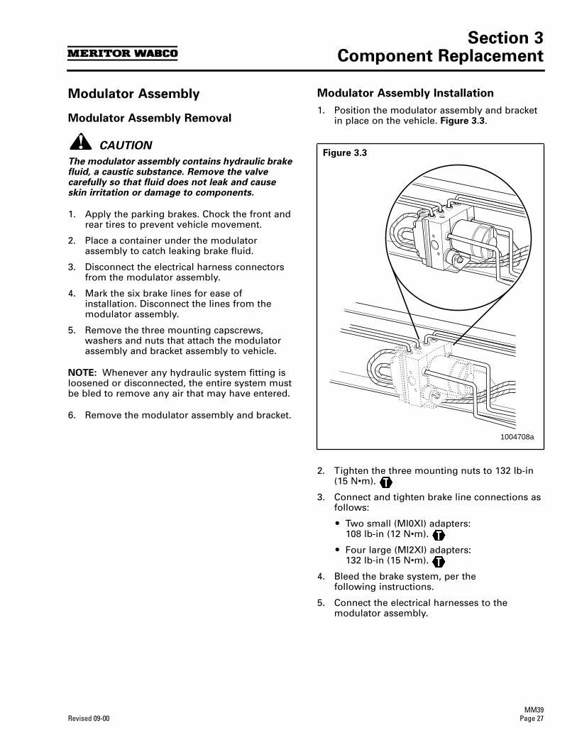
Section 3Component Replacement
MM39Revised 09-00 Page 27
Modulator Assembly
Modulator Assembly Removal
CAUTION
The modulator assembly contains hydraulic brake fluid, a caustic substance. Remove the valve carefully so that fluid does not leak and cause skin irritation or damage to components.
1. Apply the parking brakes. Chock the front and rear tires to prevent vehicle movement.
2. Place a container under the modulator assembly to catch leaking brake fluid.
3. Disconnect the electrical harness connectors from the modulator assembly.
4. Mark the six brake lines for ease of installation. Disconnect the lines from the modulator assembly.
5. Remove the three mounting capscrews, washers and nuts that attach the modulator assembly and bracket assembly to vehicle.
NOTE: Whenever any hydraulic system fitting is loosened or disconnected, the entire system must be bled to remove any air that may have entered.
6. Remove the modulator assembly and bracket.
Modulator Assembly Installation
1. Position the modulator assembly and bracket in place on the vehicle. Figure 3.3.
2. Tighten the three mounting nuts to 132 lb-in (15 N•m).
3. Connect and tighten brake line connections as follows:
r Two small (MI0XI) adapters:108 lb-in (12 N•m).
r Four large (MI2XI) adapters:132 lb-in (15 N•m).
4. Bleed the brake system, per the following instructions.
5. Connect the electrical harnesses to the modulator assembly.
Figure 3.3
1004708a
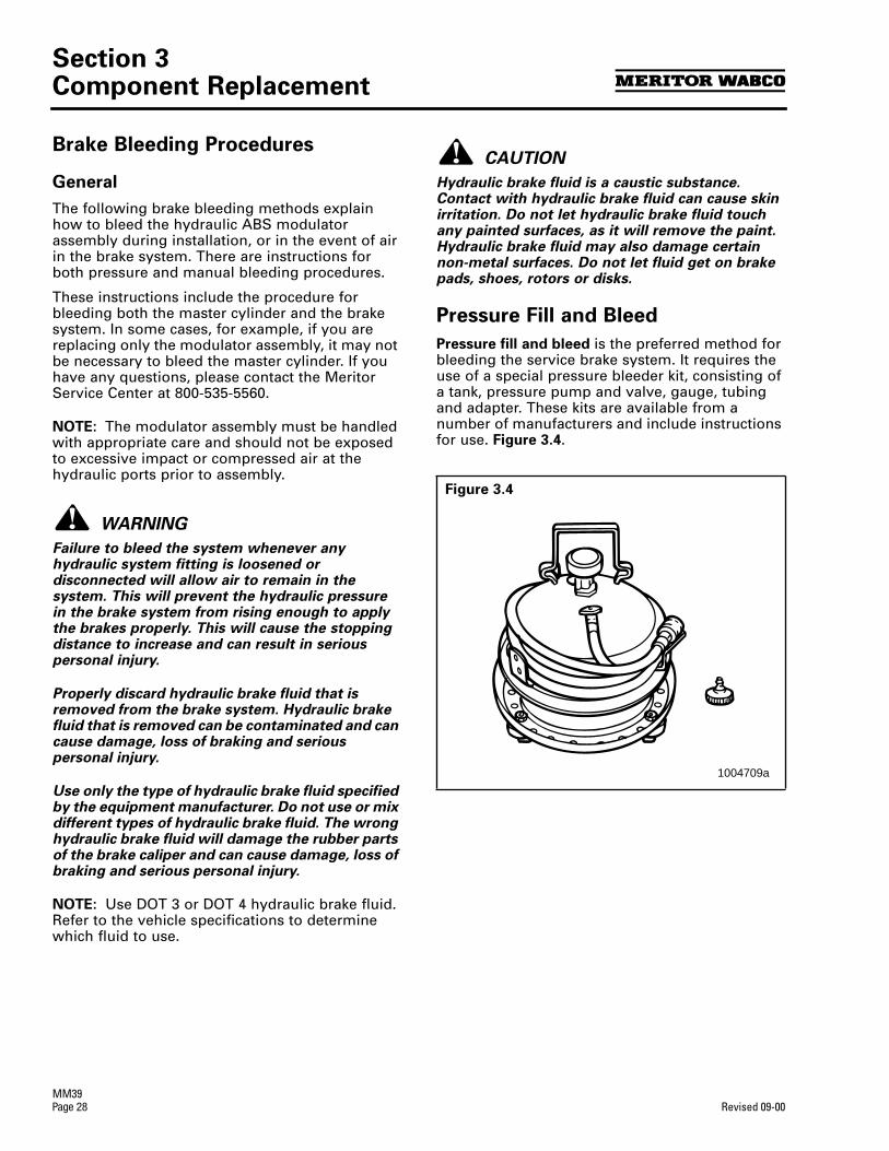
Section 3Component Replacement
MM39Page 28 Revised 09-00
Brake Bleeding Procedures
General
The following brake bleeding methods explain how to bleed the hydraulic ABS modulator assembly during installation, or in the event of air in the brake system. There are instructions for both pressure and manual bleeding procedures.
These instructions include the procedure for bleeding both the master cylinder and the brake system. In some cases, for example, if you are replacing only the modulator assembly, it may not be necessary to bleed the master cylinder. If you have any questions, please contact the Meritor Service Center at 800-535-5560.
NOTE: The modulator assembly must be handled with appropriate care and should not be exposed to excessive impact or compressed air at the hydraulic ports prior to assembly.
WARNING
Failure to bleed the system whenever any hydraulic system fitting is loosened or disconnected will allow air to remain in the system. This will prevent the hydraulic pressure in the brake system from rising enough to apply the brakes properly. This will cause the stopping distance to increase and can result in serious personal injury.
Properly discard hydraulic brake fluid that is removed from the brake system. Hydraulic brake fluid that is removed can be contaminated and can cause damage, loss of braking and serious personal injury.
Use only the type of hydraulic brake fluid specified by the equipment manufacturer. Do not use or mix different types of hydraulic brake fluid. The wrong hydraulic brake fluid will damage the rubber parts of the brake caliper and can cause damage, loss of braking and serious personal injury.
NOTE: Use DOT 3 or DOT 4 hydraulic brake fluid. Refer to the vehicle specifications to determine which fluid to use.
CAUTION
Hydraulic brake fluid is a caustic substance. Contact with hydraulic brake fluid can cause skin irritation. Do not let hydraulic brake fluid touch any painted surfaces, as it will remove the paint. Hydraulic brake fluid may also damage certain non-metal surfaces. Do not let fluid get on brake pads, shoes, rotors or disks.
Pressure Fill and Bleed
Pressure fill and bleed is the preferred method for bleeding the service brake system. It requires the use of a special pressure bleeder kit, consisting of a tank, pressure pump and valve, gauge, tubing and adapter. These kits are available from a number of manufacturers and include instructions for use. Figure 3.4.
Figure 3.4
1004709a
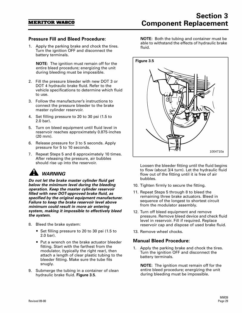
Section 3Component Replacement
MM39Revised 09-00 Page 29
Pressure Fill and Bleed Procedure:
1. Apply the parking brake and chock the tires. Turn the ignition OFF and disconnect the battery terminals.
NOTE: The ignition must remain off for the entire bleed procedure; energizing the unit during bleeding must be impossible.
2. Fill the pressure bleeder with new DOT 3 or DOT 4 hydraulic brake fluid. Refer to the vehicle specifications to determine which fluid to use.
3. Follow the manufacturer’s instructions to connect the pressure bleeder to the brake master cylinder reservoir.
4. Set filling pressure to 20 to 30 psi (1.5 to2.0 bar).
5. Turn on bleed equipment until fluid level in reservoir reaches approximately 0.875-inches (20 mm).
6. Release pressure for 3 to 5 seconds. Apply pressure for 5 to 10 seconds.
7. Repeat Steps 5 and 6 approximately 10 times. After releasing the pressure, air bubbles should rise up into the reservoir.
WARNING
Do not let the brake master cylinder fluid get below the minimum level during the bleeding operation. Keep the master cylinder reservoir filled with new DOT-approved brake fluid, as specified by the original equipment manufacturer. Failure to keep the brake reservoir level above minimum could result in more air entering system, making it impossible to effectively bleed the system.
8. Bleed the brake system:
r Set filling pressure to 20 to 30 psi (1.5 to 2.0 bar).
r Put a wrench on the brake actuator bleeder fitting. Start with the farthest from the modulator, (typically the right rear), then attach a length of clear plastic tubing to the bleeder fitting. Make sure the tube fits snugly.
9. Submerge the tubing in a container of clean hydraulic brake fluid. Figure 3.5.
NOTE: Both the tubing and container must be able to withstand the effects of hydraulic brake fluid.
Loosen the bleeder fitting until the fluid begins to flow (about 3/4 turn). Let the hydraulic fluid flow out of the fitting until it is free of air bubbles.
10. Tighten firmly to secure the fitting.
11. Repeat Steps 5 through 8 to bleed the remaining three brake actuators. Bleed in sequence of the longest to shortest circuit from the modulator assembly.
12. Turn off bleed equipment and remove pressure. Remove bleed device and check fluid level in reservoir. Fill if required. Replace reservoir cap and dispose of used brake fluid.
13. Remove wheel chocks.
Manual Bleed Procedure:
1. Apply the parking brake and chock the tires. Turn the ignition OFF and disconnect the battery terminals.
NOTE: The ignition must remain off for the entire bleed procedure; energizing the unit during bleeding must be impossible.
Figure 3.5
1004710a
Section 3Component Replacement
MM39Page 30 Revised 09-00
2. Fill the reservoir with DOT 3 or DOT 4 hydraulic brake fluid. Refer to the vehicle specifications to determine which fluid to use.
3. Depress the brake pedal five times using the stroke between 1/3 travel and maximum travel in 5 seconds.
4. Release the pedal for 5 to 10 seconds. Air bubbles will rise into the reservoir while depressing and releasing pedal.
5. Repeat Steps 3 and 4 another three times, or until sufficient pedal resistance is felt.
WARNING
Do not let the brake master cylinder fluid get below the minimum level during the bleeding operation. Keep the master cylinder reservoir filled with new DOT-approved brake fluid as specified by the original equipment manufacturer. Failure to keep the brake reservoir level above minimum could result in more air entering system, making it impossible to effectively bleed the system.
6. Bleed the brake system. Put a wrench on the brake actuator bleeder fitting. Start with the farthest from the modulator, (typically the right rear), then attach a length of clear plastic tubing to the bleeder fitting. Make sure the tube fits snugly.
7. Submerge the tubing in a container of clean brake fluid. Figure 3.5.
NOTE: Both the tubing and container must be able to withstand the effects of brake fluid.
8. Depress the brake pedal 10 to 15 times, using the maximum available stroke.
9. Loosen the bleeder fitting until the fluid begins to flow, (about 3/4 turn), while depressing the brake pedal through its maximum available stroke.
10. Tighten the fitting firmly prior to releasing the brake pedal.
11. Repeat Steps 6 through 8 several times until the discharged fluid is free of air bubbles.
12. Repeat Steps 3 through 9 to bleed the remaining three brake actuators. Bleed in sequence of the longest to the shortest circuit from the modulator.
13. Check the travel of the brake pedal. If a firm resistance is felt the manual bleeding procedure is complete.
14. Check the fluid level in reservoir and fill if required. Replace reservoir cap and dispose of used brake fluid.
15. Remove wheel chocks.

Section 4Appendix A
MM39Revised 09-00 Page 31
Section 4Appendix A
Modulator Assembly Connector Pin Assignment
Pin Number Circuit Description
Pin Number Circuit Description
1 Outlet Valve RL 8 Reference Ground
2 Inlet Valve RL 9 – – – – –
3 – – – – – 10 Outlet Valve RR
4 Inlet Valve FR 11 Inlet Valve RR
5 Outlet Valve FR 12 Inlet Valve FL
6 – – – – – 13 Outlet Valve FL
7 – – – – –
1 2 3 4 5
6 7 8 9
10 11 12 13
MAINGROUND
+-
PUMPCONNECTOR
MODULATOR ASSEMBLYCONNECTOR PINOUT
5 4 3 2 1
9 8 7 6
13 12 11 10
HARNESSCONNECTOR PINOUT
1004711a

Meritor WABCOVehicle Control Systems3331 West Big Beaver Road, Suite 300Troy, MI 48084 USA800-535-5560www.arvinmeritor.com
Information contained in this publication was in effect at the time the publication was approved for printing and is subject to change without notice or liability. Meritor WABCO reserves the right to revise the information presented or discontinue the production of parts described at any time.
Copyright 2000 Meritor WABCOAll Rights Reserved Printed in the USA
Maintenance Manual 39Revised 09-00
16579/24240

TP-20192
Issued 10-00
Technical Bulletin
Meritor WABCO
Vehicle Control Systems3331 West Big Beaver Road, Suite 300Troy, MI 48084 USA800-535-5560www.arvinmeritor.com
Information contained in this publication was in effect at the time the publication was approved for printing and is subject to change without notice or liability. ArvinMeritor Commercial Vehicle Systems reserves the right to revise the information presented or discontinue the production of parts described at any time.
Copyright 2000 TP-20192ArvinMeritor, Inc. Issued 10-00All Rights Reserved Printed in the USA 16579/ArvinMeritor
Proper Sensor Adjustment for Hydraulic ABS
For proper hydraulic ABS operation, all wheel-end sensors must be properly installed and maintained, as follows:
At installation, the sensor must be installed to initially contact the tooth wheel. The center of the sensor must contact the tooth wheel near the center of the tooth wheel, at least 0.12-inch (3 mm) from the edge of the tooth. No gap is allowable at installation.
When adjusting the sensor, push the sensor completely into the sensor spring clip until it contacts the tooth wheel. During normal operation a gap not to exceed 0.04-inch (1 mm) is allowable.
Meritor WABCO specifications call for a mineral oil-based lubricant for the sensor spring clip and sensor that contains molydisulfide. It should have excellent anti-corrosion and adhesion characteristics and be capable of continuous function in a temperature range of -40° to 300° F(-40° to 150° C).
For complete Hydraulic ABS troubleshooting and maintenance information, please refer to Maintenance Manual 38,
C-version Hydraulic ABS,
or Maintenance Manual 39,
D-version Hydraulic ABS
. To order a maintenance manual, call ArvinMeritor’s Customer Service Center at 800-535-5560 or go on-line at www.arvinmeritor.com and download a copy from our technical library.
ME
RIT
OR WABCO
WH
A TY O U N E E D
T OK
NO
WTOOLBOXSOFTWARE
User’s Manual
TP-99102Rev 01-04
Diagnostic and On-Screen Service Instructions For:
Pneumatic ABS (D and E Versions)
Trailer ABS (Easy-StopTM and Enhanced Easy-StopTM with PLC)
Hydraulic ABS (HABS)
Hydraulic Power Brake (HPB)
Electronic Leveling Module (ELM) for Tractors
Electronic Leveling Module (ELM) for Trailers
TM
TOOLBOXSOFTWARE

Table of Contents
TP-99102Revised 01-04 Page -1
Table of Contents
Introduction . . . . . . . . . . . . . . . . . . . . . . . . . . . . . . . . . . . . . . . . . . . . . . . . . . . . . . . . 1System Requirements . . . . . . . . . . . . . . . . . . . . . . . . . . . . . . . . . . . . . . . . . . . . . . . . . . . .2Installation . . . . . . . . . . . . . . . . . . . . . . . . . . . . . . . . . . . . . . . . . . . . . . . . . . . . . . . . . . . . .3Starting TOOLBOXTM Software . . . . . . . . . . . . . . . . . . . . . . . . . . . . . . . . . . . . . . . . . . . . .3Main Menu . . . . . . . . . . . . . . . . . . . . . . . . . . . . . . . . . . . . . . . . . . . . . . . . . . . . . . . . . . . . .4
Main Menu . . . . . . . . . . . . . . . . . . . . . . . . . . . . . . . . . . . . . . . . . . . . . . . . . . . . . . . . . 5System Setup . . . . . . . . . . . . . . . . . . . . . . . . . . . . . . . . . . . . . . . . . . . . . . . . . . . . . . . . . . .5Language . . . . . . . . . . . . . . . . . . . . . . . . . . . . . . . . . . . . . . . . . . . . . . . . . . . . . . . . . . . . . .5Select ECU . . . . . . . . . . . . . . . . . . . . . . . . . . . . . . . . . . . . . . . . . . . . . . . . . . . . . . . . . . . . .6COM Port . . . . . . . . . . . . . . . . . . . . . . . . . . . . . . . . . . . . . . . . . . . . . . . . . . . . . . . . . . . . . . .6Vendor . . . . . . . . . . . . . . . . . . . . . . . . . . . . . . . . . . . . . . . . . . . . . . . . . . . . . . . . . . . . . . . . .7Protocol . . . . . . . . . . . . . . . . . . . . . . . . . . . . . . . . . . . . . . . . . . . . . . . . . . . . . . . . . . . . . . . .7Device . . . . . . . . . . . . . . . . . . . . . . . . . . . . . . . . . . . . . . . . . . . . . . . . . . . . . . . . . . . . . . . . .8Help . . . . . . . . . . . . . . . . . . . . . . . . . . . . . . . . . . . . . . . . . . . . . . . . . . . . . . . . . . . . . . . . . . .8System Information . . . . . . . . . . . . . . . . . . . . . . . . . . . . . . . . . . . . . . . . . . . . . . . . . . . . . .8Update Applications (Versions 5.0 and Higher) . . . . . . . . . . . . . . . . . . . . . . . . . . . . . . . .9About . . . . . . . . . . . . . . . . . . . . . . . . . . . . . . . . . . . . . . . . . . . . . . . . . . . . . . . . . . . . . . . . . .9
Tractor ABS . . . . . . . . . . . . . . . . . . . . . . . . . . . . . . . . . . . . . . . . . . . . . . . . . . . . . . . 11Reference Material . . . . . . . . . . . . . . . . . . . . . . . . . . . . . . . . . . . . . . . . . . . . . . . . . . . . . .11Main Screen . . . . . . . . . . . . . . . . . . . . . . . . . . . . . . . . . . . . . . . . . . . . . . . . . . . . . . . . . . .11Restart Exit Help . . . . . . . . . . . . . . . . . . . . . . . . . . . . . . . . . . . . . . . . . . . . . . . . . . . . . . . .12Tractor ECU . . . . . . . . . . . . . . . . . . . . . . . . . . . . . . . . . . . . . . . . . . . . . . . . . . . . . . . . . . . .12Display . . . . . . . . . . . . . . . . . . . . . . . . . . . . . . . . . . . . . . . . . . . . . . . . . . . . . . . . . . . . . . . .12Faults . . . . . . . . . . . . . . . . . . . . . . . . . . . . . . . . . . . . . . . . . . . . . . . . . . . . . . . . . . . . . . . .13Wheel Speed . . . . . . . . . . . . . . . . . . . . . . . . . . . . . . . . . . . . . . . . . . . . . . . . . . . . . . . . . . .14Memorized Data (E Version ABS Only) . . . . . . . . . . . . . . . . . . . . . . . . . . . . . . . . . . . . .15RSC Data (E Version ABS Only) . . . . . . . . . . . . . . . . . . . . . . . . . . . . . . . . . . . . . . . . . . .16Component Tests . . . . . . . . . . . . . . . . . . . . . . . . . . . . . . . . . . . . . . . . . . . . . . . . . . . . . . .17Valves . . . . . . . . . . . . . . . . . . . . . . . . . . . . . . . . . . . . . . . . . . . . . . . . . . . . . . . . . . . . . . . .17RSC Trailer Valve (E Version ABS Only) . . . . . . . . . . . . . . . . . . . . . . . . . . . . . . . . . . . . .18Lamps . . . . . . . . . . . . . . . . . . . . . . . . . . . . . . . . . . . . . . . . . . . . . . . . . . . . . . . . . . . . . . . .19Relay . . . . . . . . . . . . . . . . . . . . . . . . . . . . . . . . . . . . . . . . . . . . . . . . . . . . . . . . . . . . . . . . .19Engine Data Link . . . . . . . . . . . . . . . . . . . . . . . . . . . . . . . . . . . . . . . . . . . . . . . . . . . . . . .20Disable ATC . . . . . . . . . . . . . . . . . . . . . . . . . . . . . . . . . . . . . . . . . . . . . . . . . . . . . . . . . . .20Enable ATC . . . . . . . . . . . . . . . . . . . . . . . . . . . . . . . . . . . . . . . . . . . . . . . . . . . . . . . . . . . .21Reset Memorized . . . . . . . . . . . . . . . . . . . . . . . . . . . . . . . . . . . . . . . . . . . . . . . . . . . . . . .21
Trailer ABS . . . . . . . . . . . . . . . . . . . . . . . . . . . . . . . . . . . . . . . . . . . . . . . . . . . . . . . . 23Reference Material . . . . . . . . . . . . . . . . . . . . . . . . . . . . . . . . . . . . . . . . . . . . . . . . . . . . . .23Main Screen . . . . . . . . . . . . . . . . . . . . . . . . . . . . . . . . . . . . . . . . . . . . . . . . . . . . . . . . . . .23Restart Exit Help . . . . . . . . . . . . . . . . . . . . . . . . . . . . . . . . . . . . . . . . . . . . . . . . . . . . . . . .24Trailer ECU . . . . . . . . . . . . . . . . . . . . . . . . . . . . . . . . . . . . . . . . . . . . . . . . . . . . . . . . . . . .24Language Restart . . . . . . . . . . . . . . . . . . . . . . . . . . . . . . . . . . . . . . . . . . . . . . . . . . . . . . .24Manual Setup . . . . . . . . . . . . . . . . . . . . . . . . . . . . . . . . . . . . . . . . . . . . . . . . . . . . . . . . . .25Print . . . . . . . . . . . . . . . . . . . . . . . . . . . . . . . . . . . . . . . . . . . . . . . . . . . . . . . . . . . . . . . . . .25Save . . . . . . . . . . . . . . . . . . . . . . . . . . . . . . . . . . . . . . . . . . . . . . . . . . . . . . . . . . . . . . . . . .25Display . . . . . . . . . . . . . . . . . . . . . . . . . . . . . . . . . . . . . . . . . . . . . . . . . . . . . . . . . . . . . . . .27Faults . . . . . . . . . . . . . . . . . . . . . . . . . . . . . . . . . . . . . . . . . . . . . . . . . . . . . . . . . . . . . . . . .27Fault Information . . . . . . . . . . . . . . . . . . . . . . . . . . . . . . . . . . . . . . . . . . . . . . . . . . . . . . .27Component Tests . . . . . . . . . . . . . . . . . . . . . . . . . . . . . . . . . . . . . . . . . . . . . . . . . . . . . . .28Valve and Lamp Activation . . . . . . . . . . . . . . . . . . . . . . . . . . . . . . . . . . . . . . . . . . . . . . .28Valves . . . . . . . . . . . . . . . . . . . . . . . . . . . . . . . . . . . . . . . . . . . . . . . . . . . . . . . . . . . . . . . .29Lamp . . . . . . . . . . . . . . . . . . . . . . . . . . . . . . . . . . . . . . . . . . . . . . . . . . . . . . . . . . . . . . . . .29Sensors . . . . . . . . . . . . . . . . . . . . . . . . . . . . . . . . . . . . . . . . . . . . . . . . . . . . . . . . . . . . . . .30Sensor Orientation Test (For Enhanced Easy-StopTM Only) . . . . . . . . . . . . . . . . . . . . .32Modify . . . . . . . . . . . . . . . . . . . . . . . . . . . . . . . . . . . . . . . . . . . . . . . . . . . . . . . . . . . . . . . .33Service Information . . . . . . . . . . . . . . . . . . . . . . . . . . . . . . . . . . . . . . . . . . . . . . . . . . . . .33Tire Calibration . . . . . . . . . . . . . . . . . . . . . . . . . . . . . . . . . . . . . . . . . . . . . . . . . . . . . . . . .34Reconfigure . . . . . . . . . . . . . . . . . . . . . . . . . . . . . . . . . . . . . . . . . . . . . . . . . . . . . . . . . . . .35Notebook . . . . . . . . . . . . . . . . . . . . . . . . . . . . . . . . . . . . . . . . . . . . . . . . . . . . . . . . . . . . .35Lift Axle . . . . . . . . . . . . . . . . . . . . . . . . . . . . . . . . . . . . . . . . . . . . . . . . . . . . . . . . . . . . . . .36Plant Location/OEM . . . . . . . . . . . . . . . . . . . . . . . . . . . . . . . . . . . . . . . . . . . . . . . . . . . . .36
tool.bk.book Page -1 Wednesday, April 14, 2004 12:22 PM
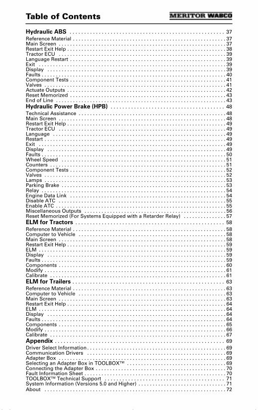
Table of Contents
Hydraulic ABS . . . . . . . . . . . . . . . . . . . . . . . . . . . . . . . . . . . . . . . . . . . . . . . . . . . . . 37Reference Material . . . . . . . . . . . . . . . . . . . . . . . . . . . . . . . . . . . . . . . . . . . . . . . . . . . . . . 37Main Screen . . . . . . . . . . . . . . . . . . . . . . . . . . . . . . . . . . . . . . . . . . . . . . . . . . . . . . . . . . . 37Restart Exit Help . . . . . . . . . . . . . . . . . . . . . . . . . . . . . . . . . . . . . . . . . . . . . . . . . . . . . . . . 38Tractor ECU . . . . . . . . . . . . . . . . . . . . . . . . . . . . . . . . . . . . . . . . . . . . . . . . . . . . . . . . . . . 39Language Restart . . . . . . . . . . . . . . . . . . . . . . . . . . . . . . . . . . . . . . . . . . . . . . . . . . . . . . . 39Exit . . . . . . . . . . . . . . . . . . . . . . . . . . . . . . . . . . . . . . . . . . . . . . . . . . . . . . . . . . . . . . . . . . 39Display . . . . . . . . . . . . . . . . . . . . . . . . . . . . . . . . . . . . . . . . . . . . . . . . . . . . . . . . . . . . . . . 39Faults . . . . . . . . . . . . . . . . . . . . . . . . . . . . . . . . . . . . . . . . . . . . . . . . . . . . . . . . . . . . . . . . . 40Component Tests . . . . . . . . . . . . . . . . . . . . . . . . . . . . . . . . . . . . . . . . . . . . . . . . . . . . . . . 41Valves . . . . . . . . . . . . . . . . . . . . . . . . . . . . . . . . . . . . . . . . . . . . . . . . . . . . . . . . . . . . . . . . 41Actuate Outputs . . . . . . . . . . . . . . . . . . . . . . . . . . . . . . . . . . . . . . . . . . . . . . . . . . . . . . . . 42Reset Memorized . . . . . . . . . . . . . . . . . . . . . . . . . . . . . . . . . . . . . . . . . . . . . . . . . . . . . . . 43End of Line . . . . . . . . . . . . . . . . . . . . . . . . . . . . . . . . . . . . . . . . . . . . . . . . . . . . . . . . . . . . 43Hydraulic Power Brake (HPB) . . . . . . . . . . . . . . . . . . . . . . . . . . . . . . . . . . . . . . . 48Technical Assistance . . . . . . . . . . . . . . . . . . . . . . . . . . . . . . . . . . . . . . . . . . . . . . . . . . . . 48Main Screen . . . . . . . . . . . . . . . . . . . . . . . . . . . . . . . . . . . . . . . . . . . . . . . . . . . . . . . . . . . 48Restart Exit Help . . . . . . . . . . . . . . . . . . . . . . . . . . . . . . . . . . . . . . . . . . . . . . . . . . . . . . . . 49Tractor ECU . . . . . . . . . . . . . . . . . . . . . . . . . . . . . . . . . . . . . . . . . . . . . . . . . . . . . . . . . . . 49Language . . . . . . . . . . . . . . . . . . . . . . . . . . . . . . . . . . . . . . . . . . . . . . . . . . . . . . . . . . . . . 49Restart . . . . . . . . . . . . . . . . . . . . . . . . . . . . . . . . . . . . . . . . . . . . . . . . . . . . . . . . . . . . . . . . 49Exit . . . . . . . . . . . . . . . . . . . . . . . . . . . . . . . . . . . . . . . . . . . . . . . . . . . . . . . . . . . . . . . . . . 49Display . . . . . . . . . . . . . . . . . . . . . . . . . . . . . . . . . . . . . . . . . . . . . . . . . . . . . . . . . . . . . . . 49Faults . . . . . . . . . . . . . . . . . . . . . . . . . . . . . . . . . . . . . . . . . . . . . . . . . . . . . . . . . . . . . . . . . 50Wheel Speed . . . . . . . . . . . . . . . . . . . . . . . . . . . . . . . . . . . . . . . . . . . . . . . . . . . . . . . . . . 51Counters . . . . . . . . . . . . . . . . . . . . . . . . . . . . . . . . . . . . . . . . . . . . . . . . . . . . . . . . . . . . . . 51Component Tests . . . . . . . . . . . . . . . . . . . . . . . . . . . . . . . . . . . . . . . . . . . . . . . . . . . . . . . 52Valves . . . . . . . . . . . . . . . . . . . . . . . . . . . . . . . . . . . . . . . . . . . . . . . . . . . . . . . . . . . . . . . . 52Lamps . . . . . . . . . . . . . . . . . . . . . . . . . . . . . . . . . . . . . . . . . . . . . . . . . . . . . . . . . . . . . . . . 53Parking Brake . . . . . . . . . . . . . . . . . . . . . . . . . . . . . . . . . . . . . . . . . . . . . . . . . . . . . . . . . . 53Relay . . . . . . . . . . . . . . . . . . . . . . . . . . . . . . . . . . . . . . . . . . . . . . . . . . . . . . . . . . . . . . . . . 54Engine Data Link . . . . . . . . . . . . . . . . . . . . . . . . . . . . . . . . . . . . . . . . . . . . . . . . . . . . . . . 54Disable ATC . . . . . . . . . . . . . . . . . . . . . . . . . . . . . . . . . . . . . . . . . . . . . . . . . . . . . . . . . . . 55Enable ATC . . . . . . . . . . . . . . . . . . . . . . . . . . . . . . . . . . . . . . . . . . . . . . . . . . . . . . . . . . . . 55Miscellaneous Outputs . . . . . . . . . . . . . . . . . . . . . . . . . . . . . . . . . . . . . . . . . . . . . . . . . . 56Reset Memorized (For Systems Equipped with a Retarder Relay) . . . . . . . . . . . . . . . 57ELM for Tractors . . . . . . . . . . . . . . . . . . . . . . . . . . . . . . . . . . . . . . . . . . . . . . . . . . . 58Reference Material . . . . . . . . . . . . . . . . . . . . . . . . . . . . . . . . . . . . . . . . . . . . . . . . . . . . . . 58Computer to Vehicle . . . . . . . . . . . . . . . . . . . . . . . . . . . . . . . . . . . . . . . . . . . . . . . . . . . . 58Main Screen . . . . . . . . . . . . . . . . . . . . . . . . . . . . . . . . . . . . . . . . . . . . . . . . . . . . . . . . . . . 58Restart Exit Help . . . . . . . . . . . . . . . . . . . . . . . . . . . . . . . . . . . . . . . . . . . . . . . . . . . . . . . . 59ELM . . . . . . . . . . . . . . . . . . . . . . . . . . . . . . . . . . . . . . . . . . . . . . . . . . . . . . . . . . . . . . . . . . 59Display . . . . . . . . . . . . . . . . . . . . . . . . . . . . . . . . . . . . . . . . . . . . . . . . . . . . . . . . . . . . . . . 59Faults . . . . . . . . . . . . . . . . . . . . . . . . . . . . . . . . . . . . . . . . . . . . . . . . . . . . . . . . . . . . . . . . . 59Components . . . . . . . . . . . . . . . . . . . . . . . . . . . . . . . . . . . . . . . . . . . . . . . . . . . . . . . . . . . 60Modify . . . . . . . . . . . . . . . . . . . . . . . . . . . . . . . . . . . . . . . . . . . . . . . . . . . . . . . . . . . . . . . . 61Calibrate . . . . . . . . . . . . . . . . . . . . . . . . . . . . . . . . . . . . . . . . . . . . . . . . . . . . . . . . . . . . . . 61ELM for Trailers . . . . . . . . . . . . . . . . . . . . . . . . . . . . . . . . . . . . . . . . . . . . . . . . . . . . 63Reference Material . . . . . . . . . . . . . . . . . . . . . . . . . . . . . . . . . . . . . . . . . . . . . . . . . . . . . . 63Computer to Vehicle . . . . . . . . . . . . . . . . . . . . . . . . . . . . . . . . . . . . . . . . . . . . . . . . . . . . 63Main Screen . . . . . . . . . . . . . . . . . . . . . . . . . . . . . . . . . . . . . . . . . . . . . . . . . . . . . . . . . . . 63Restart Exit Help . . . . . . . . . . . . . . . . . . . . . . . . . . . . . . . . . . . . . . . . . . . . . . . . . . . . . . . . 64ELM . . . . . . . . . . . . . . . . . . . . . . . . . . . . . . . . . . . . . . . . . . . . . . . . . . . . . . . . . . . . . . . . . . 64Display . . . . . . . . . . . . . . . . . . . . . . . . . . . . . . . . . . . . . . . . . . . . . . . . . . . . . . . . . . . . . . . 64Faults . . . . . . . . . . . . . . . . . . . . . . . . . . . . . . . . . . . . . . . . . . . . . . . . . . . . . . . . . . . . . . . . . 64Components . . . . . . . . . . . . . . . . . . . . . . . . . . . . . . . . . . . . . . . . . . . . . . . . . . . . . . . . . . . 65Modify . . . . . . . . . . . . . . . . . . . . . . . . . . . . . . . . . . . . . . . . . . . . . . . . . . . . . . . . . . . . . . . . 66Calibrate . . . . . . . . . . . . . . . . . . . . . . . . . . . . . . . . . . . . . . . . . . . . . . . . . . . . . . . . . . . . . . 67Appendix . . . . . . . . . . . . . . . . . . . . . . . . . . . . . . . . . . . . . . . . . . . . . . . . . . . . . . . . . . 69Driver Select Information . . . . . . . . . . . . . . . . . . . . . . . . . . . . . . . . . . . . . . . . . . . . . . . . . 69Communication Drivers . . . . . . . . . . . . . . . . . . . . . . . . . . . . . . . . . . . . . . . . . . . . . . . . . 69Adapter Box . . . . . . . . . . . . . . . . . . . . . . . . . . . . . . . . . . . . . . . . . . . . . . . . . . . . . . . . . . . 69Selecting an Adapter Box in TOOLBOXTM . . . . . . . . . . . . . . . . . . . . . . . . . . . . . . . . . . . 69Connecting the Adapter Box . . . . . . . . . . . . . . . . . . . . . . . . . . . . . . . . . . . . . . . . . . . . . . 70Fault Information Sheet . . . . . . . . . . . . . . . . . . . . . . . . . . . . . . . . . . . . . . . . . . . . . . . . . . 70TOOLBOXTM Technical Support . . . . . . . . . . . . . . . . . . . . . . . . . . . . . . . . . . . . . . . . . 71System Information (Versions 5.0 and Higher) . . . . . . . . . . . . . . . . . . . . . . . . . . . . . . . 71About . . . . . . . . . . . . . . . . . . . . . . . . . . . . . . . . . . . . . . . . . . . . . . . . . . . . . . . . . . . . . . . . 72
tool.bk.book Page 0 Wednesday, April 14, 2004 12:22 PM

Introduction
TP-99102Revised 01-04 Page 1
Introduction
Introduction Meritor WABCO TOOLBOXTM Software is a PC-based diagnostics program that runs in Windows® 98, Me, NT, 2000 or XPa. TOOLBOXTM Software provides PC diagnostic capabilities for Meritor WABCO tractor and trailer pneumatic ABS, hydraulic ABS and the electronic leveling module (ELM) for both tractor and trailer. The program provides four basic functions: • Displays both constant (e.g., ECU number)
and changing (e.g., RPMs) information from the system under test.
• Displays both active and stored system faults, as well as the appropriate repair instructions.
• Provides a link to service information testing procedures, etc. (ABS and HABS only)
• Activates system components to verify system integrity, correct component operation and installation wiring.
NOTE: For complete Meritor WABCO maintenance information, refer to the appropriate maintenance manual which is listed in this manual at the beginning of each product section. For copies of Meritor WABCO service literature, contact the ArvinMeritor Customer Service Center at 800-535-5560 or visit our website: meritorwabco.com
a Early versions of TOOLBOXTM (Version 4.2 or lower) will run in Windows® 95.
tool.bk.book Page 1 Wednesday, April 14, 2004 12:22 PM

Introduction
TP-99102Page 2 Revised 01-04
System Requirements
• Pentium-based personal computer• Microsoft Windows® 98, Me, 2000 or XPa.
Internet Explorer version 3.02 or higher must be installed.
NOTE: You must have Administrator Privileges to install and run TOOLBOXTM Software on Windows® NT.
• 64 MB RAM• Approximately 10.0 MB hard disk space for
each program. 60 MB hard disk space for full install
• CD-ROM drive• RS232 to SAE J1708 or RS232 to PLC
converter cable• Serial Port. RS232-SAE J1708 interface
adapter required• Meritor WABCO recommends using a
mouse with this program
Windows® is a registered trademark of the Microsoft Corporation.
a Windows® versions approved for use with TOOLBOXTM as of 01/04.
tool.bk.book Page 2 Wednesday, April 14, 2004 12:22 PM
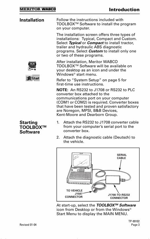
Introduction
TP-99102Revised 01-04 Page 3
Installation Follow the instructions included with TOOLBOXTM Software to install the program on your computer.
The installation screen offers three types of installations: Typical, Compact and Custom. Select Typical or Compact to install tractor, trailer and hydraulic ABS diagnostic programs. Select Custom to install only one or two of these programs.
After installation, Meritor WABCO TOOLBOXTM Software will be available on your desktop as an icon and under the Windows® start menu.Refer to “System Setup” on page 5 for first-time use instructions.NOTE: An RS232 to J1708 or RS232 to PLC converter box attached to the communications port on your computer (COM1 or COM2) is required. Converter boxes that have been tested and proven satisfactory are Noregon, MPSI, B&B Devices, Kent-Moore and Dearborn Group.
Starting TOOLBOXTM Software
1. Attach the RS232 to J1708 converter cable from your computer’s serial port to the converter box.
2. Attach the diagnostic cable (Deutsch) to the vehicle.
At start-up, select the TOOLBOXTM Software icon from Desktop or from the Windows® Start Menu to display the MAIN MENU.
TO VEHICLEJ1587
CONNECTOR
SERIALCABLE
J1708-TO-RS232CONNECTOR
tool.bk.book Page 3 Wednesday, April 14, 2004 12:22 PM
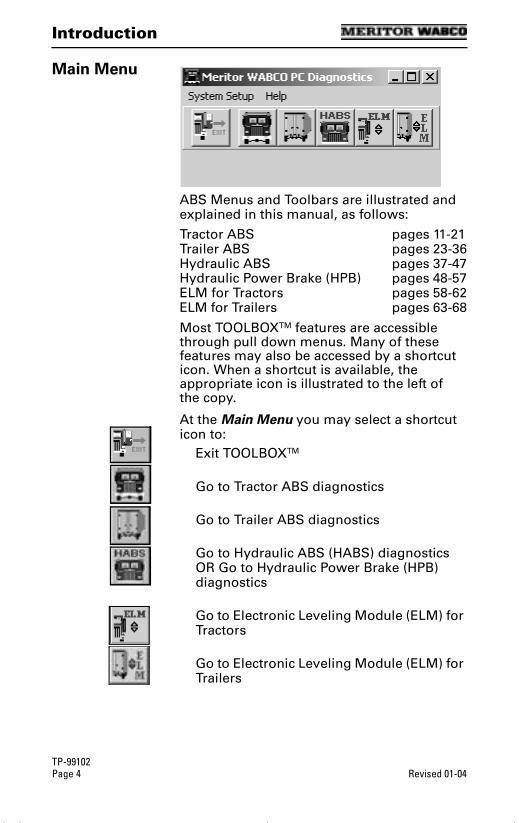
Introduction
TP-99102Page 4 Revised 01-04
Main Menu
ABS Menus and Toolbars are illustrated and explained in this manual, as follows:
Tractor ABS pages 11-21Trailer ABS pages 23-36Hydraulic ABS pages 37-47Hydraulic Power Brake (HPB) pages 48-57ELM for Tractors pages 58-62ELM for Trailers pages 63-68
Most TOOLBOXTM features are accessible through pull down menus. Many of these features may also be accessed by a shortcut icon. When a shortcut is available, the appropriate icon is illustrated to the left of the copy.
At the Main Menu you may select a shortcut icon to:
Exit TOOLBOXTM
Go to Tractor ABS diagnostics
Go to Trailer ABS diagnostics
Go to Hydraulic ABS (HABS) diagnostics OR Go to Hydraulic Power Brake (HPB) diagnostics
Go to Electronic Leveling Module (ELM) for Tractors
Go to Electronic Leveling Module (ELM) for Trailers
tool.bk.book Page 4 Wednesday, April 14, 2004 12:22 PM

Main Menu
TP-99102Revised 01-04 Page 5
Main Menu
Main Menu
System Setup Select System Setup from the Main Menu.
Language Select Language from the System Setup menu. The default is English. To change the default to French or Spanish (ABS only):
1. Select the appropriate language.
2. Click OK to accept the selection.
tool.bk.book Page 5 Wednesday, April 14, 2004 12:22 PM

Main Menu
TP-99102Page 6 Revised 01-04
Select ECU
Click on Select ECU from the System Setup menu, then select the type of ABS to be tested. Click on the appropriate Meritor WABCO product icon to display the Main Menu for that program.
Roll Call displays all actively broadcasting ECUs.
NOTE: TOOLBOXTM diagnostics cover only Meritor WABCO ECUs.
COM Port The correct Vendor, Protocol and Device selections are essential. TOOLBOXTM will not operate correctly if these selections are not accurate. For assistance, contact the ArvinMeritor Customer Service Center at 800-535-5560.
From the System Setup pull down menu, select COM Port to display the Device Settings menu. Current settings will be shown.
Tractor
ABS
Trailer
ABS
Hydraulic
ABS/HPB
Palm Pilot Setup:
• Go to Palm Pilot Setup Menu
• Change COM port to COM port 3
• Reboot PC
ELM
Trailer
ELM
Tractor
tool.bk.book Page 6 Wednesday, April 14, 2004 12:22 PM
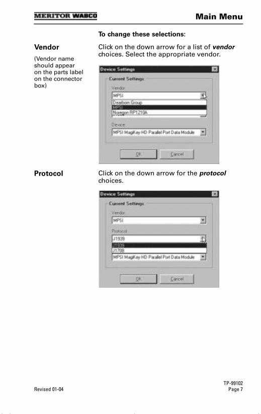
Main Menu
TP-99102Revised 01-04 Page 7
To change these selections:
Vendor
(Vendor name should appear on the parts label on the connector box)
Click on the down arrow for a list of vendor choices. Select the appropriate vendor.
Protocol Click on the down arrow for the protocol choices.
tool.bk.book Page 7 Wednesday, April 14, 2004 12:22 PM
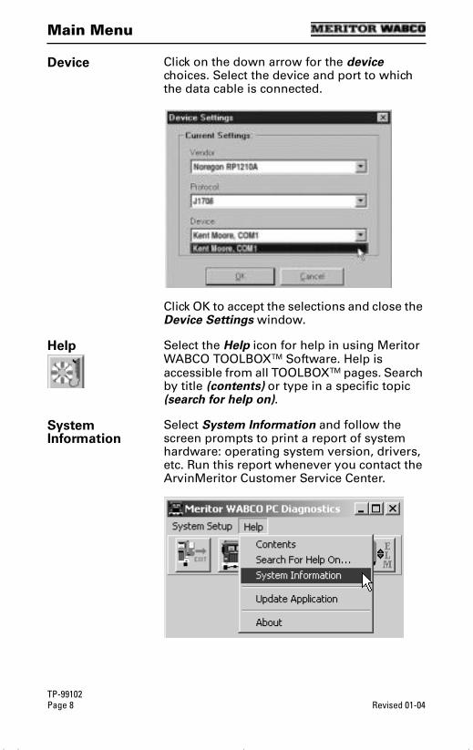
Main Menu
TP-99102Page 8 Revised 01-04
Device Click on the down arrow for the device choices. Select the device and port to which the data cable is connected.
Click OK to accept the selections and close the Device Settings window.
Help Select the Help icon for help in using Meritor WABCO TOOLBOXTM Software. Help is accessible from all TOOLBOXTM pages. Search by title (contents) or type in a specific topic (search for help on).
System Information
Select System Information and follow the screen prompts to print a report of system hardware: operating system version, drivers, etc. Run this report whenever you contact the ArvinMeritor Customer Service Center.
tool.bk.book Page 8 Wednesday, April 14, 2004 12:22 PM
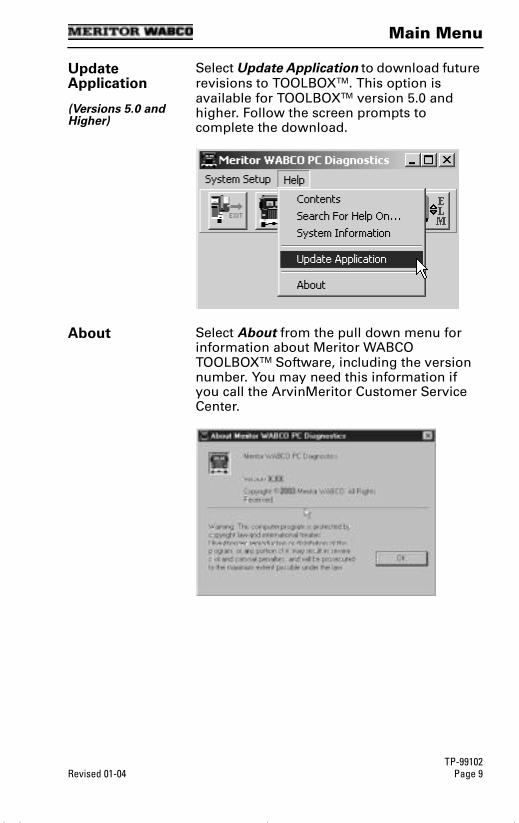
Main Menu
TP-99102Revised 01-04 Page 9
Update Application
(Versions 5.0 and Higher)
Select Update Application to download future revisions to TOOLBOXTM. This option is available for TOOLBOXTM version 5.0 and higher. Follow the screen prompts to complete the download.
About Select About from the pull down menu for information about Meritor WABCO TOOLBOXTM Software, including the version number. You may need this information if you call the ArvinMeritor Customer Service Center.
tool.bk.book Page 9 Wednesday, April 14, 2004 12:22 PM

Notes
TP-99102Page 10 Revised 01-04
Notes
tool.bk.book Page 10 Wednesday, April 14, 2004 12:22 PM

Tractor ABS
TP-99102Revised 01-04 Page 11
Tractor ABS
Tractor ABS
Reference Material
For maintenance and repair information, refer to the appropriate Meritor WABCO Truck, Tractor and Bus ABS Maintenance Manual:
MM-30 D Version ABS MM-0112 E Version ABS
NOTE: TOOLBOXTM Software must be connected to the vehicle and the vehicle ignition must be ON in order to display information.
TRACTOR ABS MENUS AND TOOLBARS
Select Tractor ABS from the TOOLBOXTM Main Menu. The Tractor ABS Main Screen will appear.
Main Screen
This screen provides icons and pull down menu task selections. It also provides information about the current state of Meritor WABCO ABS. ECU information is read once from the ECU and does not change. All other information (e.g., wheel sensors, control status, voltages, faults and road speed) is read and updated continuously.
The status of ABS switches and lamps as well as other data may be observed from this screen.
tool.bk.book Page 11 Wednesday, April 14, 2004 12:22 PM

Tractor ABS
TP-99102Page 12 Revised 01-04
RestartExitHelp
From the Main Screen you can select Restart, Exit or Help.
Tractor ECU Select Tractor ECU from the Tractor ABS Main Screen. A pull down menu will appear.
Refer to page 5 of this manual for information about using the Language selection.
Select Restart to refresh (update) ECU information.
Display Select Display from the Tractor ABS Main Screen. A pull down menu will appear.
tool.bk.book Page 12 Wednesday, April 14, 2004 12:22 PM
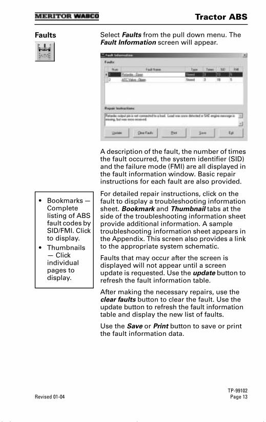
Tractor ABS
TP-99102Revised 01-04 Page 13
Faults Select Faults from the pull down menu. The Fault Information screen will appear.
A description of the fault, the number of times the fault occurred, the system identifier (SID) and the failure mode (FMI) are all displayed in the fault information window. Basic repair instructions for each fault are also provided.
For detailed repair instructions, click on the fault to display a troubleshooting information sheet. Bookmark and Thumbnail tabs at the side of the troubleshooting information sheet provide additional information. A sample troubleshooting information sheet appears in the Appendix. This screen also provides a link to the appropriate system schematic.
Faults that may occur after the screen is displayed will not appear until a screen update is requested. Use the update button to refresh the fault information table.
After making the necessary repairs, use the clear faults button to clear the fault. Use the update button to refresh the fault information table and display the new list of faults.
Use the Save or Print button to save or print the fault information data.
• Bookmarks — Complete listing of ABS fault codes by SID/FMI. Click to display.
• Thumbnails — Click individual pages to display.
tool.bk.book Page 13 Wednesday, April 14, 2004 12:22 PM
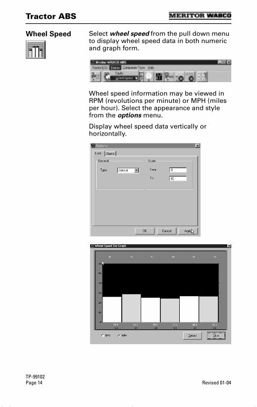
Tractor ABS
TP-99102Page 14 Revised 01-04
Wheel Speed Select wheel speed from the pull down menu to display wheel speed data in both numeric and graph form.
Wheel speed information may be viewed in RPM (revolutions per minute) or MPH (miles per hour). Select the appearance and style from the options menu.
Display wheel speed data vertically or horizontally.
tool.bk.book Page 14 Wednesday, April 14, 2004 12:22 PM
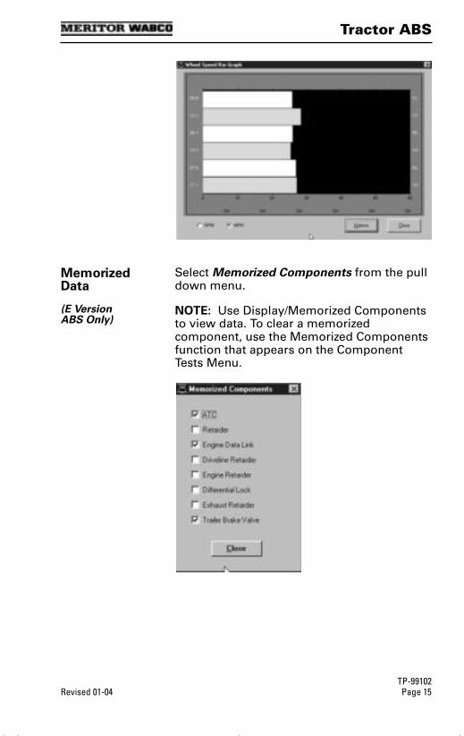
Tractor ABS
TP-99102Revised 01-04 Page 15
Memorized Data
(E VersionABS Only)
Select Memorized Components from the pull down menu.
NOTE: Use Display/Memorized Components to view data. To clear a memorized component, use the Memorized Components function that appears on the Component Tests Menu.
tool.bk.book Page 15 Wednesday, April 14, 2004 12:22 PM
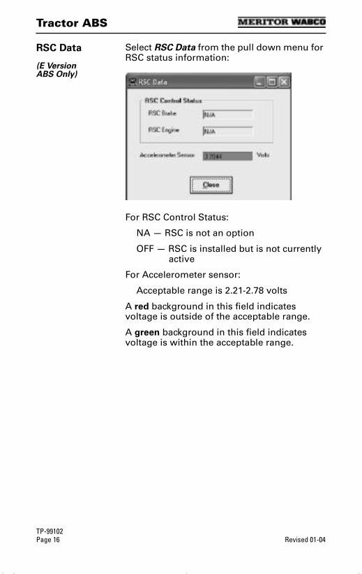
Tractor ABS
TP-99102Page 16 Revised 01-04
RSC Data
(E Version ABS Only)
Select RSC Data from the pull down menu for RSC status information:
For RSC Control Status:
NA — RSC is not an option
OFF — RSC is installed but is not currentlyactive
For Accelerometer sensor:
Acceptable range is 2.21-2.78 volts
A red background in this field indicates voltage is outside of the acceptable range.
A green background in this field indicates voltage is within the acceptable range.
tool.bk.book Page 16 Wednesday, April 14, 2004 12:22 PM
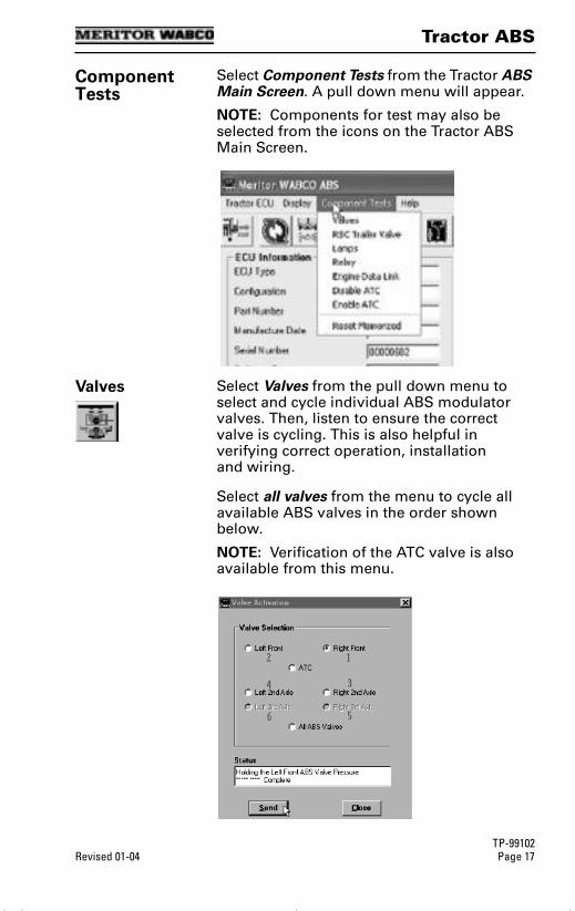
Tractor ABS
TP-99102Revised 01-04 Page 17
Component Tests
Select Component Tests from the Tractor ABS Main Screen. A pull down menu will appear.
NOTE: Components for test may also be selected from the icons on the Tractor ABS Main Screen.
Valves Select Valves from the pull down menu to select and cycle individual ABS modulator valves. Then, listen to ensure the correct valve is cycling. This is also helpful in verifying correct operation, installation and wiring.
Select all valves from the menu to cycle all available ABS valves in the order shown below.
NOTE: Verification of the ATC valve is also available from this menu.
tool.bk.book Page 17 Wednesday, April 14, 2004 12:22 PM
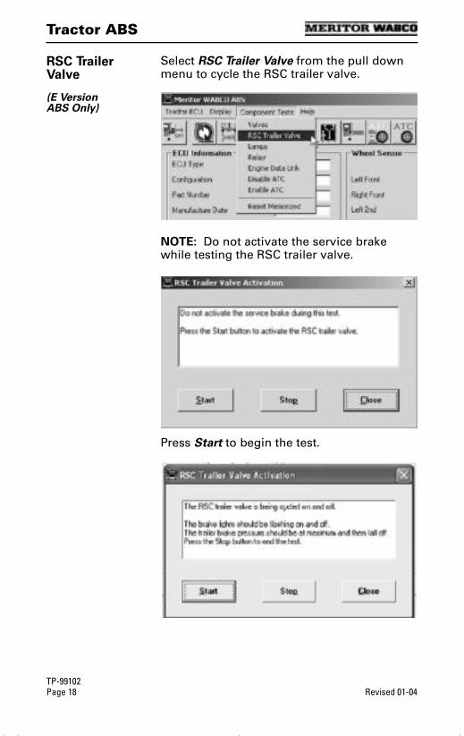
Tractor ABS
TP-99102Page 18 Revised 01-04
RSC Trailer Valve
(E Version ABS Only)
Select RSC Trailer Valve from the pull down menu to cycle the RSC trailer valve.
NOTE: Do not activate the service brake while testing the RSC trailer valve.
Press Start to begin the test.
tool.bk.book Page 18 Wednesday, April 14, 2004 12:22 PM
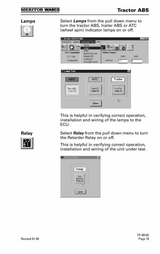
Tractor ABS
TP-99102Revised 01-04 Page 19
Lamps Select Lamps from the pull down menu to turn the tractor ABS, trailer ABS or ATC (wheel spin) indicator lamps on or off.
This is helpful in verifying correct operation, installation and wiring of the lamps to the ECU.
Relay Select Relay from the pull down menu to turn the Retarder Relay on or off.
This is helpful in verifying correct operation, installation and wiring of the unit under test.
tool.bk.book Page 19 Wednesday, April 14, 2004 12:22 PM

Tractor ABS
TP-99102Page 20 Revised 01-04
Engine Data Link
Select Engine Data Link from the pull down menu to send a “limit engine torque” command to the engine or a “disable retarder” command to the retarder.
Disable ATC Select Disable ATC from the pull down menu to send a command to the ECU to disable automatic traction control. ATC will remain disabled until the enable command is sent or the vehicle ignition is cycled. The status bar on the Main Screen reflects the current state of the ATC function, either Enabled, Disabled or N/A (not available).
Using the Disable ATC command is useful and essential for dynamometer testing.
tool.bk.book Page 20 Wednesday, April 14, 2004 12:22 PM

Tractor ABS
TP-99102Revised 01-04 Page 21
Enable ATC Select Enable ATC from the pull down menu to send a command to the ECU to enable automatic traction control. This is the normal state of the ECU. The status bar on the Main Screen reflects the current state of the ATC function, either Enabled, Disabled or N/A (not available).
Reset Memorized
Select Reset Memorized from the pull down menu to tell the ECU to reset the memorized or “learned” components.
The ECU has the ability to learn the following components: ATC valve, engine data link and retarder relay. Once any of these have been detected, the ECU expects to see them each time the ECU is powered on. If they are not seen, the ECU records a fault.
Because there are times when an ECU is moved to another vehicle — or during diagnostic testing — you may want the ECU to disregard these learned components. Use the Reset Memorized command for this purpose.
tool.bk.book Page 21 Wednesday, April 14, 2004 12:22 PM
Notes
TP-99102Page 22 Revised 01-04
Notes
tool.bk.book Page 22 Wednesday, April 14, 2004 12:22 PM
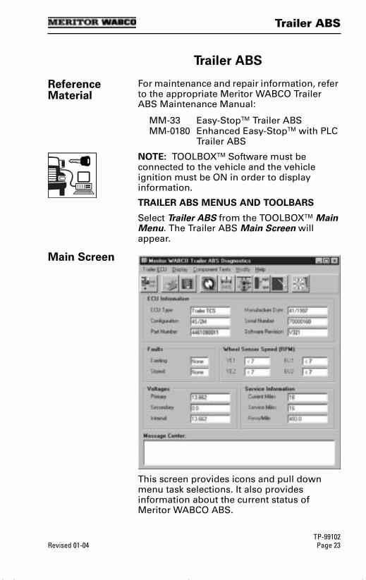
Trailer ABS
TP-99102Revised 01-04 Page 23
Trailer ABS
Trailer ABS
Reference Material
For maintenance and repair information, refer to the appropriate Meritor WABCO Trailer ABS Maintenance Manual:
MM-33 Easy-StopTM Trailer ABS MM-0180 Enhanced Easy-StopTM with PLC
Trailer ABS
NOTE: TOOLBOXTM Software must be connected to the vehicle and the vehicle ignition must be ON in order to display information.
TRAILER ABS MENUS AND TOOLBARS
Select Trailer ABS from the TOOLBOXTM Main Menu. The Trailer ABS Main Screen will appear.
Main Screen
This screen provides icons and pull down menu task selections. It also provides information about the current status of Meritor WABCO ABS.
tool.bk.book Page 23 Wednesday, April 14, 2004 12:22 PM

Trailer ABS
TP-99102Page 24 Revised 01-04
ECU information is read once from the ECU and does not change. All other information (e.g., wheel sensors, voltages and fault information) is read and updated continuously.
NOTE: Double click on Yes in the Existing or Stored Faults fields to bring up the Fault Information screen. This screen is illustrated on page 40.
Service Information may also be observed from the Trailer ABS main screen.
Restart ExitHelp
From the Main Screen, you can select Restart, Exit or Help.
Trailer ECU Select Trailer ECU from the Trailer ABS MAIN SCREEN. A pull down menu will appear.
Language Restart
Refer to page 5 of this manual for information about using the Language selection.
Select Restart to refresh (update) ECU information.
tool.bk.book Page 24 Wednesday, April 14, 2004 12:22 PM
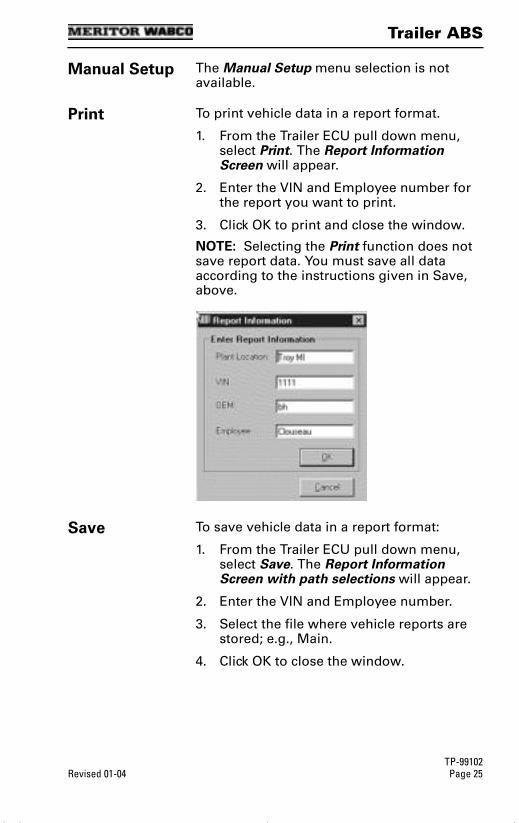
Trailer ABS
TP-99102Revised 01-04 Page 25
Manual Setup The Manual Setup menu selection is not available.
Print To print vehicle data in a report format.
1. From the Trailer ECU pull down menu, select Print. The Report Information Screen will appear.
2. Enter the VIN and Employee number for the report you want to print.
3. Click OK to print and close the window.
NOTE: Selecting the Print function does not save report data. You must save all data according to the instructions given in Save, above.
Save To save vehicle data in a report format:
1. From the Trailer ECU pull down menu, select Save. The Report Information Screen with path selections will appear.
2. Enter the VIN and Employee number.
3. Select the file where vehicle reports are stored; e.g., Main.
4. Click OK to close the window.
tool.bk.book Page 25 Wednesday, April 14, 2004 12:22 PM

Trailer ABS
TP-99102Page 26 Revised 01-04
NOTE: Trailer ABS reports are not displayed in TOOLBOXTM. To view a report, use Windows Explorer to find and open the report file. The following is a sample report.
Meritor WABCO ABS Fault Report
Date: September 13, 2000Time: 5:25 PMPage: 1VIN: 12345678Employee Information: KILEYABS System Configuration: 4S/2MECU Revision: V 3 2 2xxxxPart Number: 446-108-000-1Serial Number: 5 9 3 0 3 9 4 8xxxxxxxxxDate of Manufacture: 13/1999Current Miles: 0.0Service Miles: 0.0Tire Calibration: 495.0
Fault# Description Status SID FMI Count
1 Ext. modulator BLUE open circuit detected Active 9 5 12 Ext. modulator BLUE open circuit detected Stored 9 5 1
Sensor Test Results:
Sensor Max RPM Order
YE1 40.0 1YE2 59.0 2BU1 50.0 3BU2 38.0 4
Valve Tests Performed:
Valve Status (Tested / Not Tested / NA)
Yellow TestedBlue TestedRed N/A
tool.bk.book Page 26 Wednesday, April 14, 2004 12:22 PM

Trailer ABS
TP-99102Revised 01-04 Page 27
Display Select Display from the Trailer ABS Main Screen. A pull down menu will appear.
Faults Select Faults to display the Fault Information Screen.
NOTE: The Fault Information Screen is also accessible from the Trailer ABS Main Screen. Refer to page 23.
Fault Information
The Fault Information Screen contains a description of each fault, including the type of fault (Active or Stored), SID and FMI number. Repair instructions for the fault appear at the bottom of the screen.
For detailed repair instructions, click on the fault to display a troubleshooting information sheet. Bookmark and Thumbnail tabs at the side of the troubleshooting information sheet provide additional information. A sample troubleshooting information sheet appears in the Appendix. This screen also provides a link to the appropriate system schematic.
Faults that occur after the screen is displayed will not appear until a screen update is requested. Use the Update button at the bottom of the screen to refresh the fault information table and display a new list of faults.
• Bookmarks — Complete listing of ABS fault codes by SID/FMI. Click to display.
• Thumbnails — Click individual pages to display.
tool.bk.book Page 27 Wednesday, April 14, 2004 12:22 PM
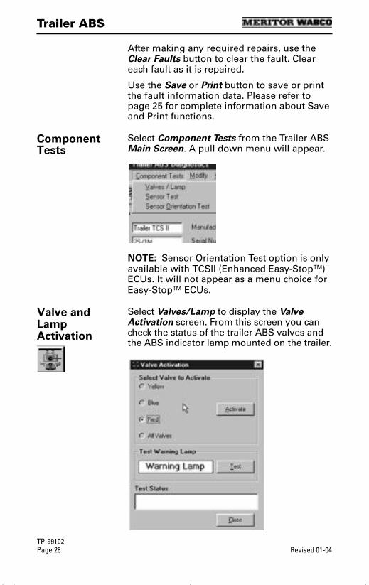
Trailer ABS
TP-99102Page 28 Revised 01-04
After making any required repairs, use the Clear Faults button to clear the fault. Clear each fault as it is repaired.
Use the Save or Print button to save or print the fault information data. Please refer to page 25 for complete information about Save and Print functions.
Component Tests
Select Component Tests from the Trailer ABS Main Screen. A pull down menu will appear.
NOTE: Sensor Orientation Test option is only available with TCSII (Enhanced Easy-StopTM) ECUs. It will not appear as a menu choice for Easy-StopTM ECUs.
Valve and Lamp Activation
Select Valves/Lamp to display the Valve Activation screen. From this screen you can check the status of the trailer ABS valves and the ABS indicator lamp mounted on the trailer.
tool.bk.book Page 28 Wednesday, April 14, 2004 12:22 PM

Trailer ABS
TP-99102Revised 01-04 Page 29
Valves 2S/1M Systems
S = SensorsM = Modulator Valves
The Red valve indicator will be selected. Click on the Activate button and listen for the valve to click, indicating a good installation.
2S/2M, 4S/2M and 4S/3M Systems
The Yellow valve indicator will be selected. Click on the Activate button and listen for the valve to click, indicating a good installation. Repeat for the Blue valve.
NOTE: Selecting All Valves will sequence all of the valves, beginning with the Yellow valve.
As each valve is cycled, the Test Status box at the bottom of the screen will display the status of the test.
Lamp Click on the Warning Lamp Test button on the bottom of the valve and lamp activation screen to activate the lamp that is mounted on the side of the trailer. The lamp will flash eight times, indicating the lamp is OK. The test status box at the bottom of the menu will display the status.
Message StatusComplete OKCritical Error Communication error (If this
message occurs, check the cable connections, recycle power.)
tool.bk.book Page 29 Wednesday, April 14, 2004 12:22 PM
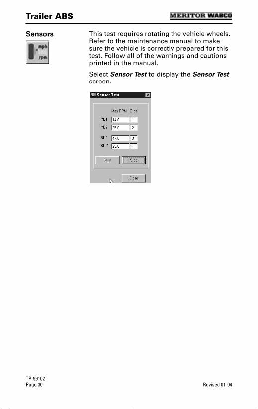
Trailer ABS
TP-99102Page 30 Revised 01-04
Sensors This test requires rotating the vehicle wheels. Refer to the maintenance manual to make sure the vehicle is correctly prepared for this test. Follow all of the warnings and cautions printed in the manual.
Select Sensor Test to display the Sensor Test screen.
tool.bk.book Page 30 Wednesday, April 14, 2004 12:22 PM
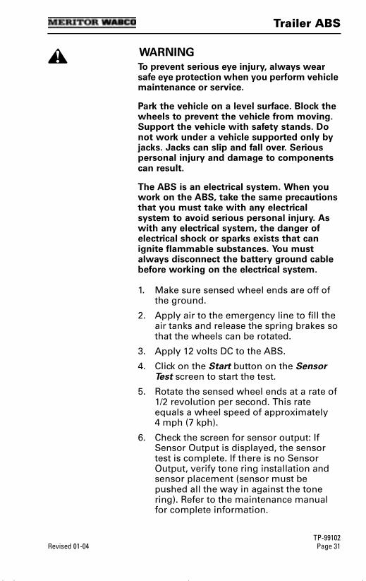
Trailer ABS
TP-99102Revised 01-04 Page 31
WARNING
To prevent serious eye injury, always wear safe eye protection when you perform vehicle maintenance or service.
Park the vehicle on a level surface. Block the wheels to prevent the vehicle from moving. Support the vehicle with safety stands. Do not work under a vehicle supported only by jacks. Jacks can slip and fall over. Serious personal injury and damage to components can result.
The ABS is an electrical system. When you work on the ABS, take the same precautions that you must take with any electrical system to avoid serious personal injury. As with any electrical system, the danger of electrical shock or sparks exists that can ignite flammable substances. You must always disconnect the battery ground cable before working on the electrical system.
1. Make sure sensed wheel ends are off of the ground.
2. Apply air to the emergency line to fill the air tanks and release the spring brakes so that the wheels can be rotated.
3. Apply 12 volts DC to the ABS.
4. Click on the Start button on the Sensor Test screen to start the test.
5. Rotate the sensed wheel ends at a rate of 1/2 revolution per second. This rate equals a wheel speed of approximately 4 mph (7 kph).
6. Check the screen for sensor output: If Sensor Output is displayed, the sensor test is complete. If there is no Sensor Output, verify tone ring installation and sensor placement (sensor must be pushed all the way in against the tone ring). Refer to the maintenance manual for complete information.
tool.bk.book Page 31 Wednesday, April 14, 2004 12:22 PM

Trailer ABS
TP-99102Page 32 Revised 01-04
7. Check the Order fields to verify sensors were installed in the right location, based on the orientation of the valves.
Sensor Orientation Test
(For Enhanced Easy-StopTM Only)
If you are using TOOLBOXTM to test an Enhanced Easy-StopTM system, you can check sensor installation by performing a sensor orientation test.
Select Sensor Orientation Test from the pull down menu. The Sensor Orientation Test screen will appear.
This test requires that the sensed wheels be spun in a predetermined order and that you enter the ECU mounting orientation. The sensed wheels are rotated in turn, starting at the front curbside, moving to the rear, and ending at the front roadside.
• A correct sensor installation will be displayed in green (Pass).
• An incorrect installation will be displayed in red (Fail).
The results of the sensor orientation test will also appear on the test page printout.
tool.bk.book Page 32 Wednesday, April 14, 2004 12:22 PM

Trailer ABS
TP-99102Revised 01-04 Page 33
Modify Select Modify from the Trailer ABS Main Menu. A pull down menu will appear.
Service Information
Select Service Information to set, change or display the odometer reading for scheduled maintenance.
When the mileage setting selected for scheduled maintenance is reached, the ABS indicator lamp on the side of the trailer will flash eight times. The lamp will continue to flash eight times whenever the ignition switch is turned on, or until service is performed and this parameter is changed. To change the mileage for the next scheduled maintenance, type in the new odometer reading, then press the Write button. Maintenance settings may be entered in miles or kilometers.
tool.bk.book Page 33 Wednesday, April 14, 2004 12:22 PM
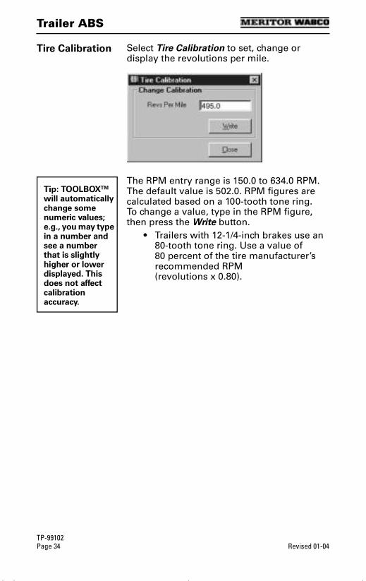
Trailer ABS
TP-99102Page 34 Revised 01-04
Tire Calibration Select Tire Calibration to set, change or display the revolutions per mile.
The RPM entry range is 150.0 to 634.0 RPM. The default value is 502.0. RPM figures are calculated based on a 100-tooth tone ring.To change a value, type in the RPM figure, then press the Write button.
• Trailers with 12-1/4-inch brakes use an 80-tooth tone ring. Use a value of 80 percent of the tire manufacturer’s recommended RPM (revolutions x 0.80).
Tip: TOOLBOXTM will automatically change some numeric values; e.g., you may type in a number and see a number that is slightly higher or lower displayed. This does not affect calibration accuracy.
tool.bk.book Page 34 Wednesday, April 14, 2004 12:22 PM
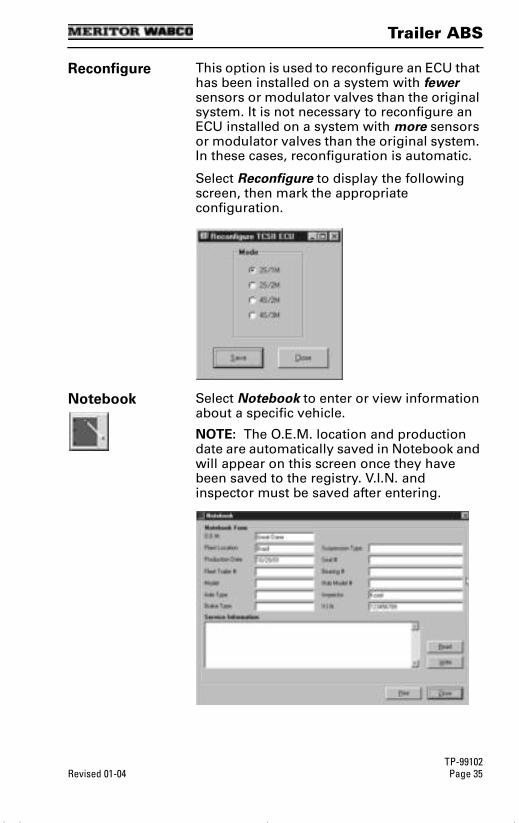
Trailer ABS
TP-99102Revised 01-04 Page 35
Reconfigure This option is used to reconfigure an ECU that has been installed on a system with fewer sensors or modulator valves than the original system. It is not necessary to reconfigure an ECU installed on a system with more sensors or modulator valves than the original system. In these cases, reconfiguration is automatic.
Select Reconfigure to display the following screen, then mark the appropriate configuration.
Notebook Select Notebook to enter or view information about a specific vehicle.
NOTE: The O.E.M. location and production date are automatically saved in Notebook and will appear on this screen once they have been saved to the registry. V.I.N. and inspector must be saved after entering.
tool.bk.book Page 35 Wednesday, April 14, 2004 12:22 PM
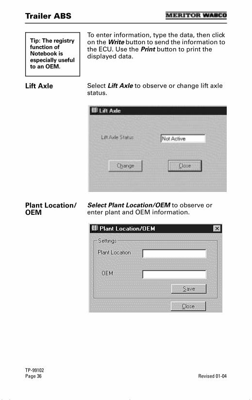
Trailer ABS
TP-99102Page 36 Revised 01-04
To enter information, type the data, then click on the Write button to send the information to the ECU. Use the Print button to print the displayed data.
Lift Axle Select Lift Axle to observe or change lift axle status.
Plant Location/OEM
Select Plant Location/OEM to observe or enter plant and OEM information.
Tip: The registry function of Notebook is especially useful to an OEM.
tool.bk.book Page 36 Wednesday, April 14, 2004 12:22 PM

Hydraulic ABS
TP-99102Revised 01-04 Page 37
Hydraulic ABS
Hydraulic ABS
Reference Material
For maintenance and repair information, refer to the Meritor WABCO Trailer ABS Maintenance Manual:
MM-39 Hydraulic ABS for Medium-Duty Trucks, Buses and Motor Home Chassis
NOTE: TOOLBOXTM Software must be connected to the vehicle and the vehicle ignition must be ON in order to display information.
HYDRAULIC ABS MENUS AND TOOLBARS
Select Hydraulic ABS from the TOOLBOXTM Main Menu. TOOLBOXTM will recognize the HABS or Hydraulic Power Brake (HPB) ECU and display the appropriate screen. If you are working with HPB, refer to the HPB section of this manual.
Main Screen
tool.bk.book Page 37 Wednesday, April 14, 2004 12:22 PM
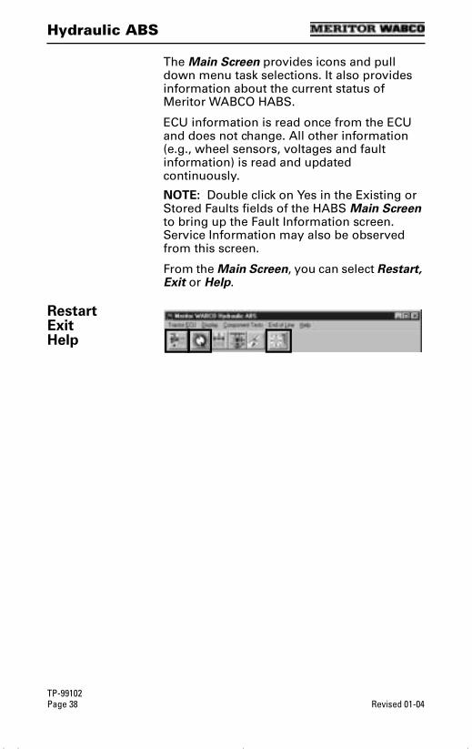
Hydraulic ABS
TP-99102Page 38 Revised 01-04
The Main Screen provides icons and pull down menu task selections. It also provides information about the current status of Meritor WABCO HABS.
ECU information is read once from the ECU and does not change. All other information (e.g., wheel sensors, voltages and fault information) is read and updated continuously.
NOTE: Double click on Yes in the Existing or Stored Faults fields of the HABS Main Screen to bring up the Fault Information screen. Service Information may also be observed from this screen.
From the Main Screen, you can select Restart, Exit or Help.
RestartExitHelp
tool.bk.book Page 38 Wednesday, April 14, 2004 12:22 PM

Hydraulic ABS
TP-99102Revised 01-04 Page 39
Tractor ECU Select Tractor ECU from the HABS Main Screen. A pull down menu will appear.
Language Restart
Refer to page 5 of this manual for information about using the Language selection.
Select Restart to refresh (update) ECU information.
Exit Select Exit to exit HABS and return to the TOOLBOXTM Main Menu.
Display Select Display from the HABS Main Screen. A pull down menu will appear.
tool.bk.book Page 39 Wednesday, April 14, 2004 12:22 PM
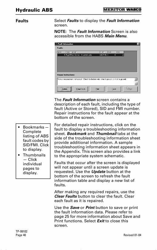
Hydraulic ABS
TP-99102Page 40 Revised 01-04
Faults Select Faults to display the Fault Information screen.
NOTE: The Fault Information Screen is also accessible from the HABS Main Menu.
The Fault Information screen contains a description of each fault, including the type of fault (Active or Stored), SID and FMI number. Repair instructions for the fault appear at the bottom of the screen.
For detailed repair instructions, click on the fault to display a troubleshooting information sheet. Bookmark and Thumbnail tabs at the side of the troubleshooting information sheet provide additional information. A sample troubleshooting information sheet appears in the Appendix. This screen also provides a link to the appropriate system schematic.
Faults that occur after the screen is displayed will not appear until a screen update is requested. Use the Update button at the bottom of the screen to refresh the fault information table and display a new list of faults.
After making any required repairs, use the Clear Faults button to clear the fault. Clear each fault as it is repaired.
Use the Save or Print button to save or print the fault information data. Please refer to page 25 for more information about Save and Print functions. Select Exit to close this screen.
• Bookmarks — Complete listing of ABS fault codes by SID/FMI. Click to display.
• Thumbnails — Click individual pages to display.
tool.bk.book Page 40 Wednesday, April 14, 2004 12:22 PM
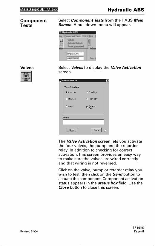
Hydraulic ABS
TP-99102Revised 01-04 Page 41
Component Tests
Select Component Tests from the HABS Main Screen. A pull down menu will appear.
Valves Select Valves to display the Valve Activation screen.
The Valve Activation screen lets you activate the four valves, the pump and the retarder relay. In addition to checking for correct activation, this screen provides an easy way to make sure the valves are wired correctly — and that wiring is not reversed.
Click on the valve, pump or retarder relay you wish to test, then click on the Send button to actuate the component. Component activation status appears in the status box field. Use the Close button to close this screen.
tool.bk.book Page 41 Wednesday, April 14, 2004 12:22 PM
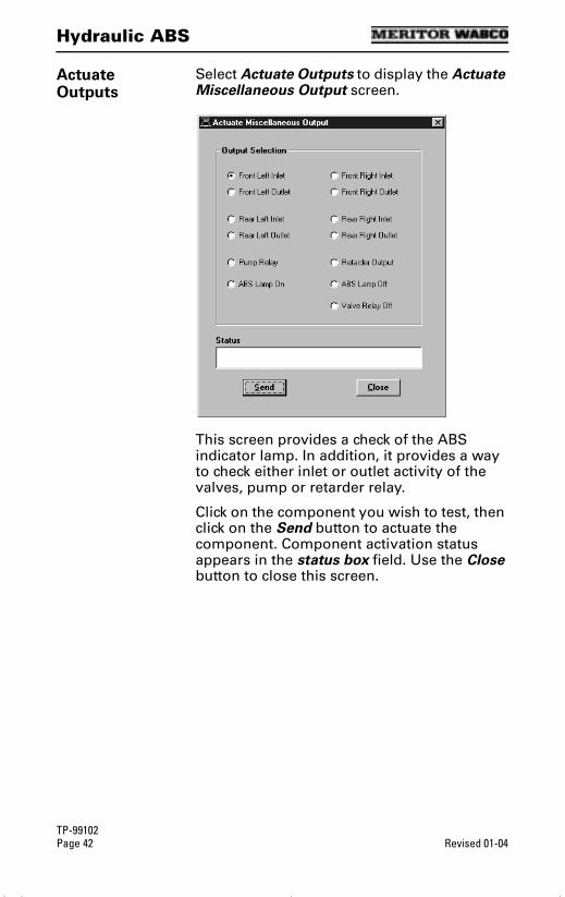
Hydraulic ABS
TP-99102Page 42 Revised 01-04
Actuate Outputs
Select Actuate Outputs to display the Actuate Miscellaneous Output screen.
This screen provides a check of the ABS indicator lamp. In addition, it provides a way to check either inlet or outlet activity of the valves, pump or retarder relay.
Click on the component you wish to test, then click on the Send button to actuate the component. Component activation status appears in the status box field. Use the Close button to close this screen.
tool.bk.book Page 42 Wednesday, April 14, 2004 12:22 PM
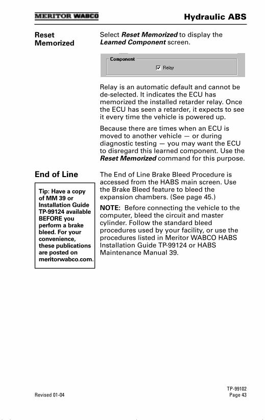
Hydraulic ABS
TP-99102Revised 01-04 Page 43
Reset Memorized
Select Reset Memorized to display the Learned Component screen.
Relay is an automatic default and cannot be de-selected. It indicates the ECU has memorized the installed retarder relay. Once the ECU has seen a retarder, it expects to see it every time the vehicle is powered up.
Because there are times when an ECU is moved to another vehicle — or during diagnostic testing — you may want the ECU to disregard this learned component. Use the Reset Memorized command for this purpose.
End of Line The End of Line Brake Bleed Procedure is accessed from the HABS main screen. Use the Brake Bleed feature to bleed the expansion chambers. (See page 45.)
NOTE: Before connecting the vehicle to the computer, bleed the circuit and master cylinder. Follow the standard bleed procedures used by your facility, or use the procedures listed in Meritor WABCO HABS Installation Guide TP-99124 or HABS Maintenance Manual 39.
Tip: Have a copy of MM 39 or Installation Guide TP-99124 available BEFORE you perform a brake bleed. For your convenience, these publications are posted on meritorwabco.com.
tool.bk.book Page 43 Wednesday, April 14, 2004 12:22 PM
Hydraulic ABS
TP-99102Page 44 Revised 01-04
WARNING
Failure to bleed the system whenever any hydraulic system fitting is loosened or disconnected will allow air to remain in the system. This will prevent the hydraulic pressure in the brake system from rising enough to apply the brakes correctly. This will cause the stopping distance to increase and can result in serious personal injury.
Correctly discard hydraulic brake fluid that is removed from the brake system. Hydraulic brake fluid that is removed can be contaminated and can cause damage, loss of braking and serious personal injury.
Use only the type of hydraulic brake fluid specified by the equipment manufacturer. Do not use or mix different types of hydraulic brake fluid. The wrong hydraulic brake fluid will damage the rubber parts of the brake caliper and can cause damage, loss of braking and serious personal injury.
Do not let the brake master cylinder fluid get below the minimum level during the bleeding operation. Keep the master cylinder reservoir filled with new DOT-approved brake fluid, as specified by the original equipment manufacturer. Failure to keep the brake reservoir level above minimum could result in more air entering system, making it impossible to effectively bleed the system.
NOTE: Use DOT 3 or DOT 4 hydraulic brake fluid. Refer to the vehicle specifications to determine which fluid to use.
tool.bk.book Page 44 Wednesday, April 14, 2004 12:22 PM
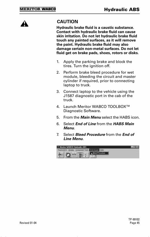
Hydraulic ABS
TP-99102Revised 01-04 Page 45
CAUTION
Hydraulic brake fluid is a caustic substance. Contact with hydraulic brake fluid can cause skin irritation. Do not let hydraulic brake fluid touch any painted surfaces, as it will remove the paint. Hydraulic brake fluid may also damage certain non-metal surfaces. Do not let fluid get on brake pads, shoes, rotors or disks.
1. Apply the parking brake and block the tires. Turn the ignition off.
2. Perform brake bleed procedure for wet module, bleeding the circuit and master cylinder if required, prior to connecting laptop to truck.
3. Connect laptop to the vehicle using the J1587 diagnostic port in the cab of the truck.
4. Launch Meritor WABCO TOOLBOXTM Diagnostic Software.
5. From the Main Menu select the HABS icon.
6. Select End of Line from the HABS Main Menu.
7. Select Bleed Procedure from the End of Line Menu.
tool.bk.book Page 45 Wednesday, April 14, 2004 12:22 PM
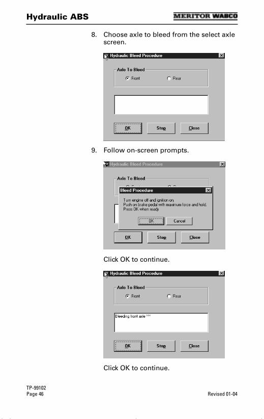
Hydraulic ABS
TP-99102Page 46 Revised 01-04
8. Choose axle to bleed from the select axle screen.
9. Follow on-screen prompts.
Click OK to continue.
Click OK to continue.
tool.bk.book Page 46 Wednesday, April 14, 2004 12:22 PM
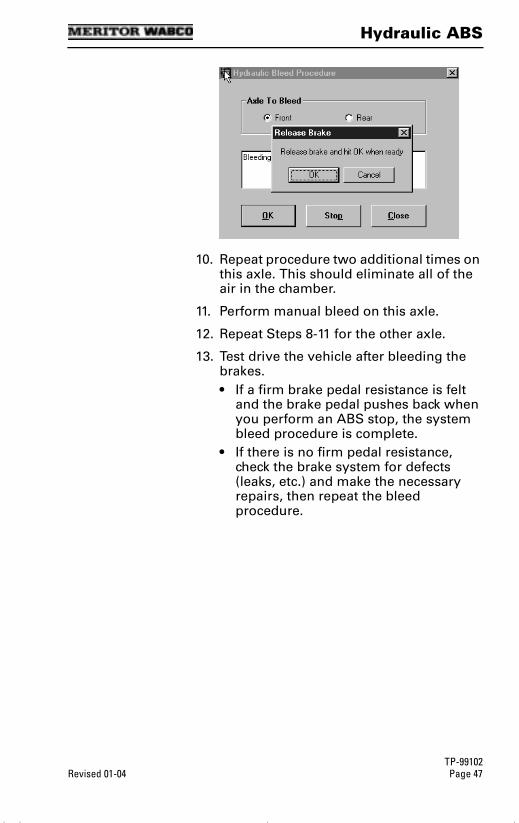
Hydraulic ABS
TP-99102Revised 01-04 Page 47
10. Repeat procedure two additional times on this axle. This should eliminate all of the air in the chamber.
11. Perform manual bleed on this axle.
12. Repeat Steps 8-11 for the other axle.
13. Test drive the vehicle after bleeding the brakes.• If a firm brake pedal resistance is felt
and the brake pedal pushes back when you perform an ABS stop, the system bleed procedure is complete.
• If there is no firm pedal resistance, check the brake system for defects (leaks, etc.) and make the necessary repairs, then repeat the bleed procedure.
tool.bk.book Page 47 Wednesday, April 14, 2004 12:22 PM
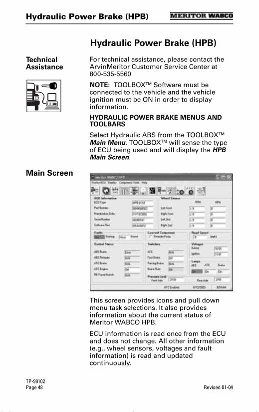
Hydraulic Power Brake (HPB)
TP-99102Page 48 Revised 01-04
Hydraulic Power Brake (HPB)
Hydraulic Power Brake (HPB)
Technical Assistance
For technical assistance, please contact the ArvinMeritor Customer Service Center at 800-535-5560
NOTE: TOOLBOXTM Software must be connected to the vehicle and the vehicle ignition must be ON in order to display information.
HYDRAULIC POWER BRAKE MENUS AND TOOLBARS
Select Hydraulic ABS from the TOOLBOXTM Main Menu. TOOLBOXTM will sense the type of ECU being used and will display the HPB Main Screen.
Main Screen
This screen provides icons and pull down menu task selections. It also provides information about the current status of Meritor WABCO HPB.
ECU information is read once from the ECU and does not change. All other information (e.g., wheel sensors, voltages and fault information) is read and updated continuously.
tool.bk.book Page 48 Wednesday, April 14, 2004 12:22 PM
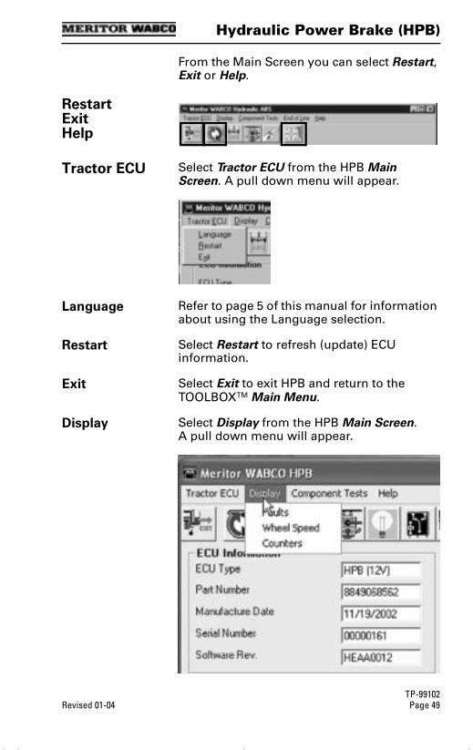
Hydraulic Power Brake (HPB)
TP-99102Revised 01-04 Page 49
From the Main Screen you can select Restart, Exit or Help.
RestartExitHelp
Tractor ECU Select Tractor ECU from the HPB Main Screen. A pull down menu will appear.
Language Refer to page 5 of this manual for information about using the Language selection.
Restart Select Restart to refresh (update) ECU information.
Exit Select Exit to exit HPB and return to the TOOLBOXTM Main Menu.
Display Select Display from the HPB Main Screen. A pull down menu will appear.
tool.bk.book Page 49 Wednesday, April 14, 2004 12:22 PM
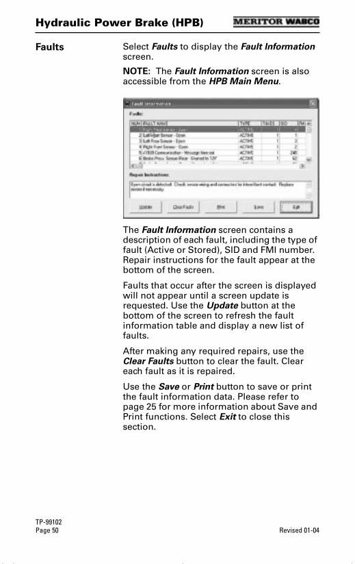
Hydraulic Power Brake (HPB)
TP-99102Page 50 Revised 01-04
Faults Select Faults to display the Fault Information screen.
NOTE: The Fault Information screen is also accessible from the HPB Main Menu.
The Fault Information screen contains a description of each fault, including the type of fault (Active or Stored), SID and FMI number. Repair instructions for the fault appear at the bottom of the screen.
Faults that occur after the screen is displayed will not appear until a screen update is requested. Use the Update button at the bottom of the screen to refresh the fault information table and display a new list of faults.
After making any required repairs, use the Clear Faults button to clear the fault. Clear each fault as it is repaired.
Use the Save or Print button to save or print the fault information data. Please refer to page 25 for more information about Save and Print functions. Select Exit to close this section.
tool.bk.book Page 50 Wednesday, April 14, 2004 12:22 PM

Hydraulic Power Brake (HPB)
TP-99102Revised 01-04 Page 51
Wheel Speed Select Wheel Speed to display the Wheel Speed screen.
Use the Wheel Speed screen to verify that sensors are connected at each wheel. Speed at a sensed wheel (FL, FR, RL, RR) indicates sensors are installed, but does not verify correct sensor installation.
Counters Select Counters to display the Counters screen.
The Counters screen provides an overview of HPB component performance (pump hours, brake events, etc.) as well as general vehicle activity such as ignition cycles. Occurrences displayed on this screen accumulate until the Clear button is selected.
tool.bk.book Page 51 Wednesday, April 14, 2004 12:22 PM
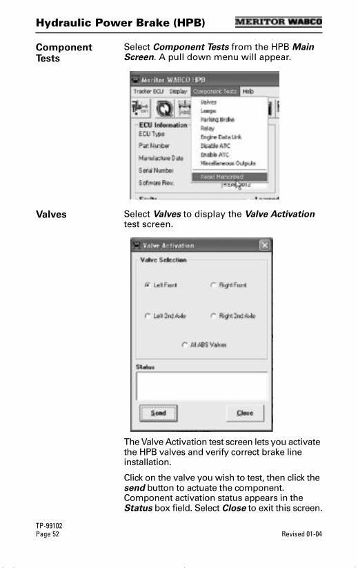
Hydraulic Power Brake (HPB)
TP-99102Page 52 Revised 01-04
Component Tests
Select Component Tests from the HPB Main Screen. A pull down menu will appear.
Valves Select Valves to display the Valve Activation test screen.
The Valve Activation test screen lets you activate the HPB valves and verify correct brake line installation.
Click on the valve you wish to test, then click the send button to actuate the component. Component activation status appears in the Status box field. Select Close to exit this screen.
tool.bk.book Page 52 Wednesday, April 14, 2004 12:22 PM
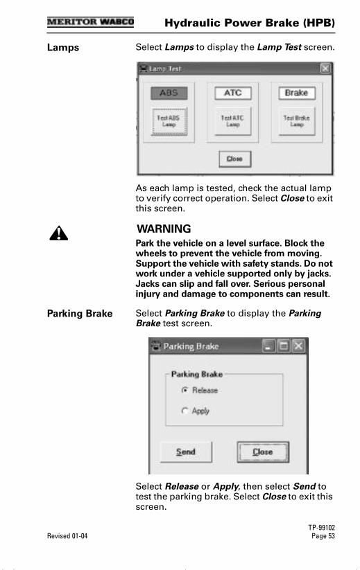
Hydraulic Power Brake (HPB)
TP-99102Revised 01-04 Page 53
Lamps Select Lamps to display the Lamp Test screen.
As each lamp is tested, check the actual lamp to verify correct operation. Select Close to exit this screen.
WARNING
Park the vehicle on a level surface. Block the wheels to prevent the vehicle from moving. Support the vehicle with safety stands. Do not work under a vehicle supported only by jacks. Jacks can slip and fall over. Serious personal injury and damage to components can result.
Parking Brake Select Parking Brake to display the Parking Brake test screen.
Select Release or Apply, then select Send to test the parking brake. Select Close to exit this screen.
tool.bk.book Page 53 Wednesday, April 14, 2004 12:22 PM

Hydraulic Power Brake (HPB)
TP-99102Page 54 Revised 01-04
Relay Select Relay to display the Activate Relay test screen.
This screen allows you to turn the Retarder Relay on or off. This is helpful in verifying correct operation, installation and wiring of the unit under test. Select Close to exit this screen.
Engine Data Link
Select Engine Data Link to display the Data Link test screen.
This screen allows you to send a “limit engine torque” command to the engine or a “disable retarder” command to the retarder.
Select the data link destination (engine or retarder), then select Send to test. Use the Stop button to end testing. Select Close to exit this screen.
tool.bk.book Page 54 Wednesday, April 14, 2004 12:22 PM
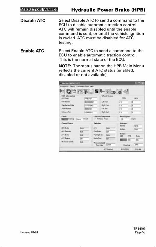
Hydraulic Power Brake (HPB)
TP-99102Revised 01-04 Page 55
Disable ATC Select Disable ATC to send a command to the ECU to disable automatic traction control. ATC will remain disabled until the enable command is sent, or until the vehicle ignition is cycled. ATC must be disabled for ATC testing.
Enable ATC Select Enable ATC to send a command to the ECU to enable automatic traction control. This is the normal state of the ECU.
NOTE: The status bar on the HPB Main Menu reflects the current ATC status (enabled, disabled or not available).
tool.bk.book Page 55 Wednesday, April 14, 2004 12:22 PM
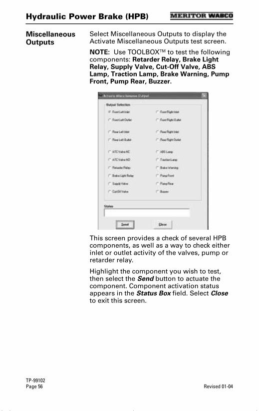
Hydraulic Power Brake (HPB)
TP-99102Page 56 Revised 01-04
Miscellaneous Outputs
Select Miscellaneous Outputs to display the Activate Miscellaneous Outputs test screen.
NOTE: Use TOOLBOXTM to test the following components: Retarder Relay, Brake Light Relay, Supply Valve, Cut-Off Valve, ABS Lamp, Traction Lamp, Brake Warning, Pump Front, Pump Rear, Buzzer.
This screen provides a check of several HPB components, as well as a way to check either inlet or outlet activity of the valves, pump or retarder relay.
Highlight the component you wish to test, then select the Send button to actuate the component. Component activation status appears in the Status Box field. Select Close to exit this screen.
tool.bk.book Page 56 Wednesday, April 14, 2004 12:22 PM
Hydraulic Power Brake (HPB)
TP-99102Revised 01-04 Page 57
Reset Memorized
(For Systems Equipped with a Retarder Relay)
Select Reset Memorized to display the Learned Component screen.
Relay is an automatic default and cannot be de-selected. It indicates the ECU has memorized the installed retarder relay. Once the ECU has seen a retarder, it expects to see it every time the vehicle is powered up.
tool.bk.book Page 57 Wednesday, April 14, 2004 12:22 PM
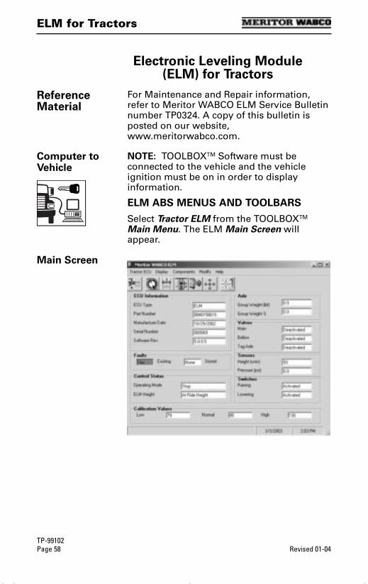
ELM for Tractors
TP-99102Page 58 Revised 01-04
ELM for Tractors
Electronic Leveling Module (ELM) for Tractors
Reference Material
For Maintenance and Repair information, refer to Meritor WABCO ELM Service Bulletin number TP0324. A copy of this bulletin is posted on our website, www.meritorwabco.com.
Computer to Vehicle
NOTE: TOOLBOXTM Software must be connected to the vehicle and the vehicle ignition must be on in order to display information.
ELM ABS MENUS AND TOOLBARS
Select Tractor ELM from the TOOLBOXTM Main Menu. The ELM Main Screen will appear.
Main Screen
tool.bk.book Page 58 Wednesday, April 14, 2004 12:22 PM
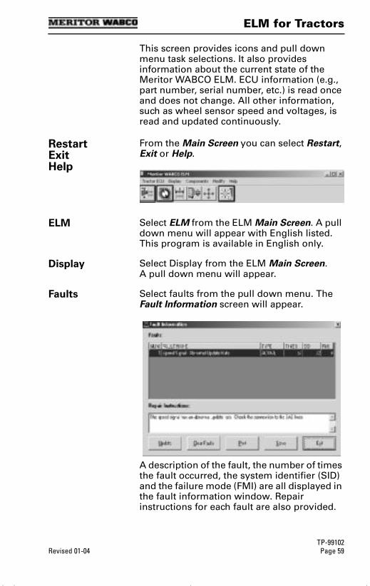
ELM for Tractors
TP-99102Revised 01-04 Page 59
This screen provides icons and pull down menu task selections. It also provides information about the current state of the Meritor WABCO ELM. ECU information (e.g., part number, serial number, etc.) is read once and does not change. All other information, such as wheel sensor speed and voltages, is read and updated continuously.
RestartExitHelp
From the Main Screen you can select Restart, Exit or Help.
ELM Select ELM from the ELM Main Screen. A pull down menu will appear with English listed. This program is available in English only.
Display Select Display from the ELM Main Screen. A pull down menu will appear.
Faults Select faults from the pull down menu. The Fault Information screen will appear.
A description of the fault, the number of times the fault occurred, the system identifier (SID) and the failure mode (FMI) are all displayed in the fault information window. Repair instructions for each fault are also provided.
tool.bk.book Page 59 Wednesday, April 14, 2004 12:22 PM
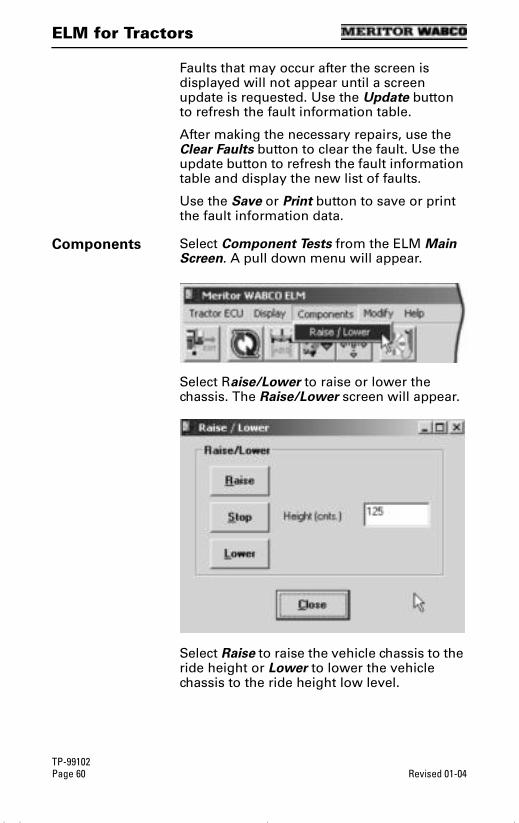
ELM for Tractors
TP-99102Page 60 Revised 01-04
Faults that may occur after the screen is displayed will not appear until a screen update is requested. Use the Update button to refresh the fault information table.
After making the necessary repairs, use the Clear Faults button to clear the fault. Use the update button to refresh the fault information table and display the new list of faults.
Use the Save or Print button to save or print the fault information data.
Components Select Component Tests from the ELM Main Screen. A pull down menu will appear.
Select Raise/Lower to raise or lower the chassis. The Raise/Lower screen will appear.
Select Raise to raise the vehicle chassis to the ride height or Lower to lower the vehicle chassis to the ride height low level.
tool.bk.book Page 60 Wednesday, April 14, 2004 12:22 PM

ELM for Tractors
TP-99102Revised 01-04 Page 61
Select Stop to halt the raising or lowering. The height of the vehicle chassis during raising or lowering is displayed on the screen in the Height field. Note that the measurement is in centimeters.
Select Close to return to the ELM Main Menu.
Modify
CAUTION: Do not modify ELM parameters unless instructed to do so by the fleet or terminal manager.
Select Modify from the ELM Main Screen. The Edit ELM Parameters screen will appear.
Calibrate At the ELM Main Menu click on the Calibration icon.
CALIBRATION ICON
tool.bk.book Page 61 Wednesday, April 14, 2004 12:22 PM
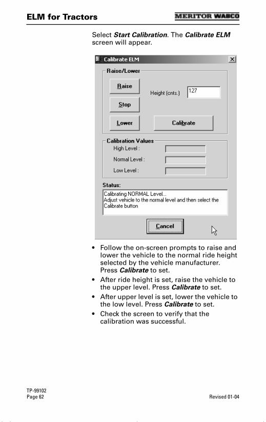
ELM for Tractors
TP-99102Page 62 Revised 01-04
Select Start Calibration. The Calibrate ELM screen will appear.
• Follow the on-screen prompts to raise and lower the vehicle to the normal ride height selected by the vehicle manufacturer. Press Calibrate to set.
• After ride height is set, raise the vehicle to the upper level. Press Calibrate to set.
• After upper level is set, lower the vehicle to the low level. Press Calibrate to set.
• Check the screen to verify that the calibration was successful.
tool.bk.book Page 62 Wednesday, April 14, 2004 12:22 PM

ELM for Trailers
TP-99102Revised 01-04 Page 63
ELM for Trailers
Electronic Leveling Module (ELM) for Trailers
Reference Material
For Maintenance and Repair information, refer to Meritor WABCO ELM Service Bulletin number TP0326. A copy of this bulletin is posted on our website, www.meritorwabco.com.
Computer to Vehicle
NOTE: TOOLBOXTM Software must be connected to the vehicle and the vehicle ignition must be ON in order to display information.
ELM ABS MENUS AND TOOLBARS
Select Trailer ELM from the TOOLBOXTM Main Menu. The ELM Main Screen will appear.
Main Screen
tool.bk.book Page 63 Wednesday, April 14, 2004 12:22 PM
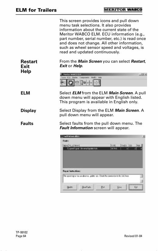
ELM for Trailers
TP-99102Page 64 Revised 01-04
This screen provides icons and pull down menu task selections. It also provides information about the current state of the Meritor WABCO ELM. ECU information (e.g., part number, serial number, etc.) is read once and does not change. All other information, such as wheel sensor speed and voltages, is read and updated continuously.
RestartExitHelp
From the Main Screen you can select Restart, Exit or Help.
ELM Select ELM from the ELM Main Screen. A pull down menu will appear with English listed. This program is available in English only.
Display Select Display from the ELM Main Screen. A pull down menu will appear.
Faults Select faults from the pull down menu. The Fault Information screen will appear.
tool.bk.book Page 64 Wednesday, April 14, 2004 12:22 PM
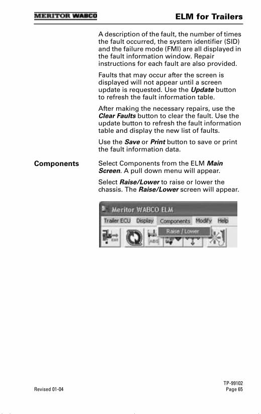
ELM for Trailers
TP-99102Revised 01-04 Page 65
A description of the fault, the number of times the fault occurred, the system identifier (SID) and the failure mode (FMI) are all displayed in the fault information window. Repair instructions for each fault are also provided.
Faults that may occur after the screen is displayed will not appear until a screen update is requested. Use the Update button to refresh the fault information table.
After making the necessary repairs, use the Clear Faults button to clear the fault. Use the update button to refresh the fault information table and display the new list of faults.
Use the Save or Print button to save or print the fault information data.
Components Select Components from the ELM Main Screen. A pull down menu will appear.
Select Raise/Lower to raise or lower the chassis. The Raise/Lower screen will appear.
tool.bk.book Page 65 Wednesday, April 14, 2004 12:22 PM
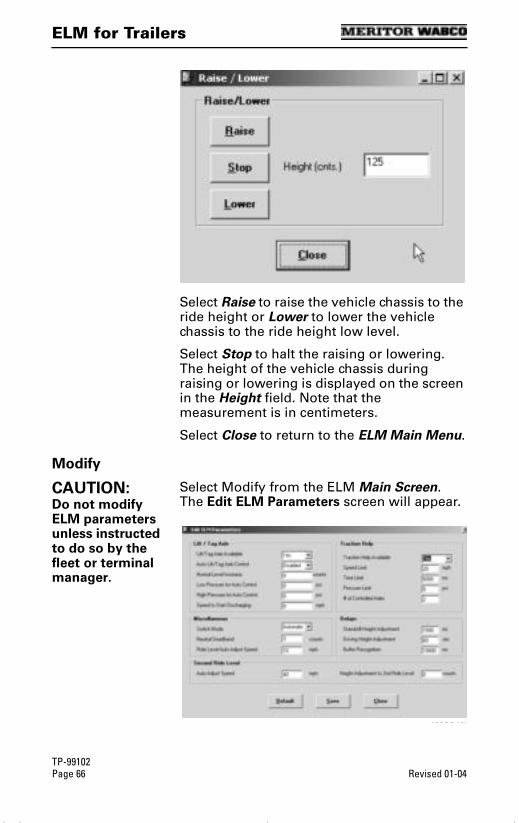
ELM for Trailers
TP-99102Page 66 Revised 01-04
Select Raise to raise the vehicle chassis to the ride height or Lower to lower the vehicle chassis to the ride height low level.
Select Stop to halt the raising or lowering. The height of the vehicle chassis during raising or lowering is displayed on the screen in the Height field. Note that the measurement is in centimeters.
Select Close to return to the ELM Main Menu.
Modify
CAUTION: Do not modify ELM parameters unless instructed to do so by the fleet or terminal manager.
Select Modify from the ELM Main Screen. The Edit ELM Parameters screen will appear.
4003012b
tool.bk.book Page 66 Wednesday, April 14, 2004 12:22 PM
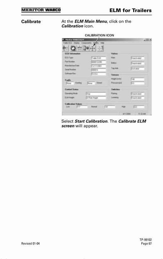
ELM for Trailers
TP-99102Revised 01-04 Page 67
Calibrate At the ELM Main Menu, click on the Calibration icon.
Select Start Calibration. The Calibrate ELM screen will appear.
CALIBRATION ICON
tool.bk.book Page 67 Wednesday, April 14, 2004 12:22 PM

ELM for Trailers
TP-99102Page 68 Revised 01-04
• Follow the on-screen prompts to raise and lower the vehicle to the normal ride height selected by the vehicle manufacturer. Press Calibrate to set.
• After ride height is set, raise the vehicle to the upper level. Press Calibrate to set.
• After upper level is set, lower the vehicle to the low level. Press Calibrate to set.
• Check the screen to verify that the calibration was successful.
tool.bk.book Page 68 Wednesday, April 14, 2004 12:22 PM
Appendix
TP-99102Revised 01-04 Page 69
Appendix
Appendix
Device Select Information
Before using TOOLBOXTM Software for the first time, you must indicate which COM port and adapter box will be used. If you have questions about Com Ports, Adapter Boxes or Drivers, the following information will answer many of your questions. Please review this material before you select the COM port and device. If you need further clarification, please contact the ArvinMeritor Customer Service Center at 1-800-535-5560.
CommunicationDrivers
Communication drivers are software programs that control the passing of data between the PC and the vehicle. Messages are sent and received via the PC’s Com port and an adapter box.
Noregon communication drivers are included with the TOOLBOXTM installation CD. These drivers are RP1210A compliant and work with most adapter boxes (refer to adapter boxes). Some adapter boxes (i.e., MPSI MagiKey and Dearborn) require communication drivers other than Noregon. These drivers must be procured from the manufacturer and installed separately.
Adapter Box An adapter box is an electronic device that connects the PC’s COM port to the vehicle’s diagnostic connector. It converts the computer’s voltages to the levels used in the truck.
Selecting an Adapter Box in TOOLBOXTM
To communicate correctly with the vehicle, TOOLBOXTM needs to know which adapter box is being used. To select an adapter box, run TOOLBOXTM. Go to the System Setup menu and select COM Port from the pull down menu. All of the installed communication drivers with be displayed on the Vendor listing.
Once a vendor has been selected, the Protocol and Device lists will be updated, and the adapter can then be selected under Devices.
tool.bk.book Page 69 Wednesday, April 14, 2004 12:22 PM
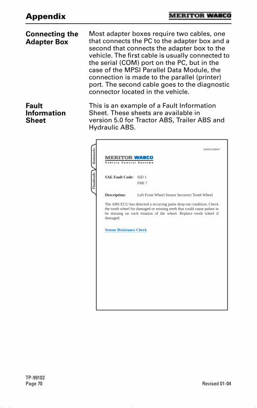
Appendix
TP-99102Page 70 Revised 01-04
Connecting the Adapter Box
Most adapter boxes require two cables, one that connects the PC to the adapter box and a second that connects the adapter box to the vehicle. The first cable is usually connected to the serial (COM) port on the PC, but in the case of the MPSI Parallel Data Module, the connection is made to the parallel (printer) port. The second cable goes to the diagnostic connector located in the vehicle.
Fault Information Sheet
This is an example of a Fault Information Sheet. These sheets are available in version 5.0 for Tractor ABS, Trailer ABS and Hydraulic ABS.
SID001FMI007
SAE Fault Code: SID 1
FMI 7
Description: Left Front Wheel Sensor Incorrect Tooth Wheel
The ABS ECU has detected a recurring pulse drop out condition. Check the tooth wheel for damaged or missing teeth that could cause pulses to be missing on each rotation of the wheel. Replace tooth wheel if damaged.
Sensor Resistance Check
Thu
mbn
ails
Boo
kmar
ks
tool.bk.book Page 70 Wednesday, April 14, 2004 12:22 PM

TOOLBOXTM Technical Support
TP-99102Revised 01-04 Page 71
TOOLBOXTM Technical Support
TOOLBOXTM Technical Support
For technical assistance, contact the ArvinMeritor Customer Service Center at 800-535-5560. Or, visit the Meritor WABCO website at www.meritorwabco.com and use the Contact Us feature to email your request to a customer service representative.
To expedite your request, you should be prepared to provide the following information.
• TOOLBOXTM Software Version Number. To find the version number:
Open TOOLBOXTM.
Click on Help, then on About PC Diagnostics.
The version number will appear on the screen.
• ECU Type
• ABS Tractor: Basic, Universal or Frame
• ABS Trailer:
Look at the ECU field on the ABS Tractor Main Screen. If ECU type is not listed, refer to the vehicle specification sheet for this information.
Electronic Leveling Module (ELM)
System Information
(Versions 5.0 and Higher)
Select System Information and follow the screen prompts to print a report of system hardware: operating system version, drivers, etc. Run this report whenever you contact the ArvinMeritor Customer Service Center.
tool.bk.book Page 71 Wednesday, April 14, 2004 12:22 PM
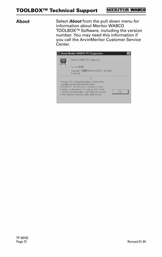
TOOLBOXTM Technical Support
TP-99102Page 72 Revised 01-04
About Select About from the pull down menu for information about Meritor WABCO TOOLBOXTM Software, including the version number. You may need this information if you call the ArvinMeritor Customer Service Center.
tool.bk.book Page 72 Wednesday, April 14, 2004 12:22 PM