section 40 0513 - los alamos national laboratory€¦ · web view · 2015-07-07section 40 0513....
TRANSCRIPT

SECTION 40 0513
PROCESS PIPING
*************************************************************************************************************LANL MASTER SPECIFICATION SECTION
This template must be edited for each project. In doing so, specifier must add job-specific requirements. Brackets are used in the text to indicate designer choices or locations where text must be supplied by the designer. Once the choice is made or text supplied, remove the brackets. This section must also be edited to delete requirements for processes, items, or designs that are not included in the project -- and specifier’s notes such as these. To seek a variance from requirements in the specifications that are applicable, contact the Engineering Standards Manual Mechanical POC. Please contact POC with suggestions for improvement as well.
When assembling a specification package, include applicable specifications from all Divisions, especially Division 1, General requirements.
This section was prepared by an organization operating under a quality assurance program that meets the requirements of 10 CFR 830 (i.e., suitable for ML-1 through ML-4 projects). Implementation of this section requires modification to meet project-specific requirements. Responsibility for application of this section to meet project-specific requirements lies with the organization modifying or implementing the section. The organization modifying the section must apply a graded approach to quality assurance based on the management level designation of the project. When this section is used with nuclear facilities subject to 10 CFR 830, modification to this section must be performed by an individual or organization operating under a quality assurance program that meets the requirements of that CFR.
Not included in this section:
1. Piping systems for liquid cryogenic fluids. Consult with cryogenic piping system manufacturer(s) for the development of such specifications and verify compliance with ASME B31.3 or other applicable B31 Code for design and construction.
2. High Pressure Piping in excess of that allowed by the ASME B1.6 Class 2500 rating for the specified design temperature and material group. Prepare a separate section for High Pressure Piping in accordance with ASME B31.3, Chapter IX and ESM Chapter 17, Pressure Safety.
3. Systems under severe cyclic conditions and/or elevated temperature service (see definition in ASME B31.3, Section 300.2). Additional requirements must be specified herein for these applications in accordance with ASME B31.3.
4. Unless required by a specific project, this section should not include piping systems which are covered in other ASME B30 series or Uniform Plumbing Code such as refrigerants (ASME B31.5), hydrogen (ASME B31.12), building chilled water and heating water (ASME B31.9), natural gas (ASME B31.8, 49CFR192, NFPA) and domestic water (Uniform Plumbing Code). Separate sections should be prepared for these applications.
LANL Project I.D. Process Piping [Rev. 0, July 25, 2012] 40 0513-1

5. For piping serving glovebox operations, Section 11 5311, Glovebox Installation, has additional information.
6. See DOE Handbook 1132, Design Considerations for piping containing radioactive materials.
This section includes pipe, fittings and ball valves for example. Additional components (check valve, relief valve, pressure reducing valve and flexible connections, etc.) required to complete a piping system must be added in this specification as applicable.
************************************************************************************************************
PART 1 GENERAL
1.1 SECTION INCLUDES
A. This section includes the general requirements for installation of process piping systems applicable to ASME B31.3, Process Piping.
************************************************************************************************************Examples include the following fluid systems. Select applicable piping specification(s) in Appendix A based on fluid, pressure and temperature, and add additional piping components and edit this section for your project. See ASME B31.3, Appendix M, Fig. M300 for classifying fluid services for fluids not listed in the examples.
*********************************************************************************************************1. Category M Fluid Service:
Hydrogen Fluoride/Hydrofluoric Acid
2. Normal Fluid Service:
Process Vacuum (Dry and Wet Vacuum), and Glovebox Atmosphere Purge/Dry, Radioactive Liquid Waste, Caustic Liquid (TRU) Waste, Liquid Fuel, Flammable Gases, Specialty Gases (Argon, Nitrogen, Helium, P-10, Regen Gas) above 150 psig or below -20F or above 366F.
3. Category D Fluid Service:
Breathing Air, Health Physics Vacuum, Specialty Gases (Argon, Nitrogen, Helium, P-10, Regen Gas) below 150 psig and -20F to 366F.
4. See ESM Chapter 17, D20-B31.3-G, ASME B31.3 Process Piping Guide, for referenced notes in Appendix A of this section, and additional information.
B. Not Included
1. Hangers and supports, insulation, and identification.
2. Piping systems for liquid cryogenic fluids
LANL Project I.D. Process Piping [Rev. 0, July 25, 2012] 40 0513-2

3. High Pressure Piping in excess of that allowed by the ASME B1.6 Class 2500 rating for the specified design temperature and material group.
4. Systems covered in other ASME B31 series or Uniform Plumbing Code such as refrigerants (ASME B31.5), hydrogen (ASME B31.12), building chilled water and heating water (ASME B31.9), natural gas (ASME B31.8, 49CFR192, NFPA) and domestic water (Uniform Plumbing Code) and thus addressed in other sections.
1.2 RELATED SECTIONS
A. Section 01 2500: Substitution Procedures
B. [Section 01 3300: Submittal Procedures]******normally addressed by Exh I****
C. [Section 01 4444: Offsite Welding and Joining Requirements]
D. [Section 01 4455: Onsite Welding and Joining Requirements]
E. [Section 11 5311.12: Glovebox Installation]
F. Section 22 0529: Hangers and Supports for Plumbing Piping and Equipment
G. Section 22 0554: Identification for Plumbing, HVAC, and Fire Protection and Equipment
H. [Section 22 0713: Plumbing and HVAC Insulation]
I. Section 22 0813: Testing Piping Systems
J. [Section 22 1500: Compressed Air Systems]
K. [Section 40 0511: Compression Fittings on Copper and Stainless Steel Tubing]
L. Section 40 0527: Piping and Tubing Inspection Checklist
1.3 REFERENCES
Most widely or uniquely used at LANL applications are listed. Not all applicable standards are listed.
A. ASME (American Society of Mechanical Engineers)
1. ASME B31 Series, Code for Pressure Piping adopted by LANL. Only ASME B31.3 applies to this specification.
a) ASME B31.3, Process Piping
2. ASME B16 Series
a) ASME B16.1, Cast Iron Pipe Flanges and Flanged Fittings
b) ASME B16.3, Malleable Iron Threaded Fittings
LANL Project I.D. Process Piping [Rev. 0, July 25, 2012] 40 0513-3

c) ASME B16.4, Gray Iron Threaded Fittings
d) ASME B16.5, Pipe Flanges and Flanged Fittings.
e) ASME B16.9, Factory Made Wrought Steel Buttwelding Fittings
f) ASME B16.10, Face to Face end End to End Dimensions of Valves
g) ASME B16.11, Forged Steel Fittings, Socket Weld and Threaded
h) ASME B16.14, Ferrous Pipe Plugs, Bushings, and Locknuts with Pipe Threads
i) ASME B16.15, Cast Bronze Threaded Fittings, Class 125 and 250
j) ASME B16.18, Cast Copper Alloy Solder Joint Pressure Fittings
k) ASME B16.20, Metallic Gaskets for Pipe Flanges: Ring Joint Spiral Wound and Jacketed.
l) ASME B16.21, Nonmetallic Flat Gaskets for Pipe Flanges.
m) ASME B16.22, Wrought Copper and Copper Alloy Solder Joint Pressure Fittings
n) ASME B16.24,Cast Copper Alloy Pipe Flanges and Flanged Fittings, Class 150,300,600,900,1500, and 2500
o) ASME B16.25, Buttwelding Ends
p) ASME B16.26, Cast Copper Alloy Fittings for Flared Copper Tubes
q) ASME B16.34, Valves-Flanged, Threaded, and Welding End
r) ASME B16.36, Orifice Flanges, Class 300,600,900,1500, and 2500
s) ASME B16.39, Malleable Iron Threaded Pipe Unions, Class 150, 250, and 300
t) ASME B16.42, Ductile Iron Pipe Flanges and Flanged Fittings, Class 150 and 300
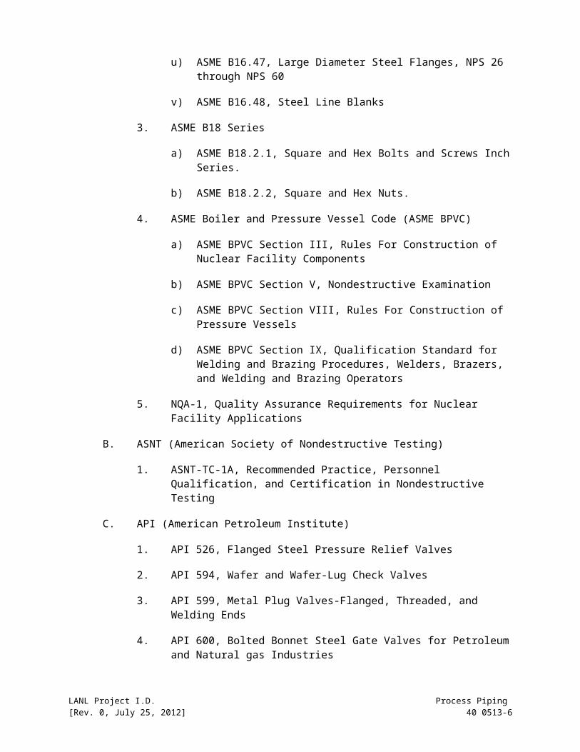
u) ASME B16.47, Large Diameter Steel Flanges, NPS 26 through NPS 60
v) ASME B16.48, Steel Line Blanks
3. ASME B18 Series
a) ASME B18.2.1, Square and Hex Bolts and Screws Inch Series.
b) ASME B18.2.2, Square and Hex Nuts.
LANL Project I.D. Process Piping [Rev. 0, July 25, 2012] 40 0513-4

4. ASME Boiler and Pressure Vessel Code (ASME BPVC)
a) ASME BPVC Section III, Rules For Construction of Nuclear Facility Components
b) ASME BPVC Section V, Nondestructive Examination
c) ASME BPVC Section VIII, Rules For Construction of Pressure Vessels
d) ASME BPVC Section IX, Qualification Standard for Welding and Brazing Procedures, Welders, Brazers, and Welding and Brazing Operators
5. NQA-1, Quality Assurance Requirements for Nuclear Facility Applications
B. ASNT (American Society of Nondestructive Testing)
1. ASNT-TC-1A, Recommended Practice, Personnel Qualification, and Certification in Nondestructive Testing
C. API (American Petroleum Institute)
1. API 526, Flanged Steel Pressure Relief Valves
2. API 594, Wafer and Wafer-Lug Check Valves
3. API 599, Metal Plug Valves-Flanged, Threaded, and Welding Ends
4. API 600, Bolted Bonnet Steel Gate Valves for Petroleum and Natural gas Industries
5. API 602, Compact Steel Gate Valves- Flanged, Threaded, Welding and Extended Body Ends
6. API 603, Class, Cast Corrosion-Resistant, Flanged-End Gate Valves
7. API 607, Fire Test for Soft-Seated Quarter Turn Valves
8. API 608, Metal Ball Valves-Flanged, Threaded, and Welding End
9. API 609, Lug and Wafer Type Butterfly Valves
10. API 6D, Specification for Pipeline Valves
D. ASTM (American Society of Testing and Material)
1. ASTM A 380, Standard Practice for Cleaning, Descaling, and Passivation of Stainless Steel Parts, Equipment, and Systems
2. ASTM G 63, Standard Guide for Evaluating Nonmetallic Materials for Oxygen Service
LANL Project I.D. Process Piping [Rev. 0, July 25, 2012] 40 0513-5
3. ASTM G 88, Guide for Designing Systems for Oxygen Service
4. ASTM G 128, Guide for Control of Hazards and Risks in Oxygen Enriched Systems
5. ASTM G 93, Standard Practice for Cleaning Methods and Cleanliness Levels for Material and Equipment Used in Oxygen Enriched Environments
6. ASTM E498, Standard Test Methods for Leaks Using the Mass Spectrometer Leak Detector in the Tracer Probe Mode
7. ASTM E499, Methods of Testing for Leaks Using the Mass Spectrometer Leak Detector in Detector Probe Mode
E. AWS (American Welding Society)
1. AWS A5.1 through 5.31, Filler Material Specifications
2. AWS QC-1, Standard for AWS Certification of Welding Inspectors
F. Compressed Gas Association
1. CGA Commodity Specifications (G-1.1: Acetylene, G-4.3: Oxygen, G-5.3: Hydrogen, G-6.2: Carbon Dioxide, G-9.1: Helium, G-10.1: Nitrogen, G-11.1: Argon)
2. CGA G-1.2, Acetylene Metering and Piping
3. CGA G-4.1, Cleaning Equipment for Oxygen Service
4. CGA G-4.4, Oxygen Pipeline Systems
5. CGA G-5.6, Hydrogen Pipeline Systems
G. DOE
1. DOE Handbook 1132, Design Considerations
2. DOE Handbook 1169, Nuclear Air Cleaning Handbook
H. LANL http://engstandards.lanl.gov
1. ESM (Engineering Standards Manual), Chapter 6, Mechanical
2. ESM, Chapter 13, Welding, Joining and NDE
3. ESM, Chapter 17, Pressure Safety
I. NFPA
1. NFPA 30, Flammable and Combustible Liquids Code
LANL Project I.D. Process Piping [Rev. 0, July 25, 2012] 40 0513-6

2. NFPA 45, Standard on Fire Protection for Laboratories Using Chemicals
3. NFPA 53, Recommended Practice on Materials, equipment, and Systems Used in Oxygen-Enriched Atmospheres
4. NFPA 54, National Fuel Gas Code
5. NFPA 55, Compressed Gases and Cryogenic Fluids Code
J. MSS (Manufacturers Standardization Society)
1. MSS SP-25, Standard Marking Systems for Valves, Fittings, Flanges, and Unions
2. MSS SP-72, Ball Valves With Flanged or Buttwelding Ends for general Service
1.4 SUBMITTALS
A. Comply with project submittal procedures.
1. For unlisted components (not listed in Table 326.1 or Appendix A of ASME B31.3), before fabrication submit approved piping stress calculations/analyses or alternative methods that document the acceptability of the specific piping system in accordance with ASME B31.3.
*************************************************************************************************************Selecting unlisted components with the maximum working pressure of at least three times the operating pressure at the same temperature with prior history is considered an acceptable means to comply with ASME B31.3.*************************************************************************************************************
PART 2 Before fabrication, submit NDE (non-destructive examination) procedures that will be used for fabrication and examination of the piping, and pressure-leak testing and cleaning procedures.
PART 3 Submittals must comply with the record requirements in ASME B31.3 for welding/bonding (Section 328.2.4/A328.2.4), examination (Section 341.4.1 & 341.4.3), procedure qualification (Section 300.2), qualification (Section 328.2.4, 342.1 & A328.2.4) and test (Section 345.2.7).
ML-1, ML-2 & ML-3 items in nuclear facilities and/or NQA-1 applications shall include, at a minimum, the following:
a) Weld (and/or Bonding for plastics) Procedure Specifications.
b) Weld (and/or Bonding for plastics) Procedure Qualification Records.
c) Welder (and/or Bonder/Bond operator) Performance Qualification Test Records.
d) Weld (and/or Bonding for plastics) Inspector Certification Records.
LANL Project I.D. Process Piping [Rev. 0, July 25, 2012] 40 0513-7

e) Pressure-Leak test reports.
f) Completed visual inspection and NDE reports.
g) Certified Material Test Reports (CMTRs) and Certificates of Compliance.
h) Product Data: For piping materials, components, and specialties.
i) Cleaning procedure and inspection records.
j) Test equipment calibration records.
k) Material control procedure, storage procedure and inspection records.
l) Qualified Examiner’s Training and Experiences.
m) Define Owner’s Inspector(s)
1.5 QUALITY ASSURANCE
A. Work shall be performed in accordance with an approved Material Control Procedure. This procedure shall describe the control methods and documentation used to handle and monitor the use of controlled materials (piping and welding filler rod and other components). The procedure shall also address procurement controls, segregation of materials, and traceability of materials from receipt at the shop through processing and final assembly. The procedure shall be submitted for approval prior to fabrication.
B. For ML-1, ML-2 & ML-3 items in nuclear facilities and ML-1 & ML-2 items in non-nuclear hazardous facilities, Subcontractors including testing agencies shall be qualified and listed in the LANL IESL (Institutional Evaluated Suppliers List). CGD (Commercial Grade Dedication) shall be used when a supplier of a nuclear safety item isn’t on the LANL IESL (hasn’t been fully qualified by LANL Supplier Quality as complying with NQA-1 and specification requirements) or where a Subcontractor (under their IESL-approved program) cannot qualify their suppliers.
C. Owner’s Inspector and the Inspector’s delegates shall have the rights to access as required by ASME B31.3, Section 340.3.
D. Qualifications
1. Welders shall be qualified in accordance with ASME BPVC Section IX.
2. Bonding of plastics: Bonder and bonding operators per ASME B31.3, Section A328.2.
1. Qualification of Examination Personnel:
a) Visual weld examinations shall be performed, and appropriate documentation prepared by Certified Welding Inspectors (CWI) who
LANL Project I.D. Process Piping [Rev. 0, July 25, 2012] 40 0513-8

have received certification in accordance with AWS QC-1-96. Certified Associate Welding Inspectors (CAWI), certified in accordance with the above standard, may perform examinations when under immediate direction of CWIs.
b) Personnel performing other examination shall be certified in accordance with Contractor’s written practice, which shall meet the requirements of ASNT SNT-TC-1A. Use Level II or III personnel to interpret results. See ESM Chapter 13, Volume 6 (Welding Inspection and General NDE). Other examinations may include receipt inspection, assembly inspection and weld inspection and leak testing.
c) For nonmetal piping, comply with ASME B31.3, Section A342.
d) Examination records including examiner’s qualifications and procedures shall be retained for at least 5 years per ASME B31.3, Section 346.3.
2. Steel Support Welding: Qualify processes and operators to AWS D1.1/D1.1M.
E. Delivery, Storage and Handling
1. For nuclear applications, classify items per NQA-1, Subpart 2.2 and comply with its Packaging, Shipping, Storage, Handling and Records requirements.
a) Valve actuators and gaskets: Level B
b) Valves and welding rods (fillers): Level C
c) Piping and fittings: Level D
2. Follow manufacturer’s requirements for storage and handling.
PART 2 PRODUCTS
3.1 PRODUCT OPTIONS AND SUBSTITUTIONS
A. Comply with Section 01630, Product Options and Substitutions.
3.2 MANUFACTURERS
See Appendix A.
***************************************************************************************************Design notes1. Threaded joints should be avoided in any service where crevice corrosion, severe erosion or
cyclic loading (pressure or thermal) may occur.2. Gasket materials shall be compatible with the fluids and service conditions.***************************************************************************************************+
LANL Project I.D. Process Piping [Rev. 0, July 25, 2012] 40 0513-9

PART 3 EXECUTION
3.1 INSTALLATION
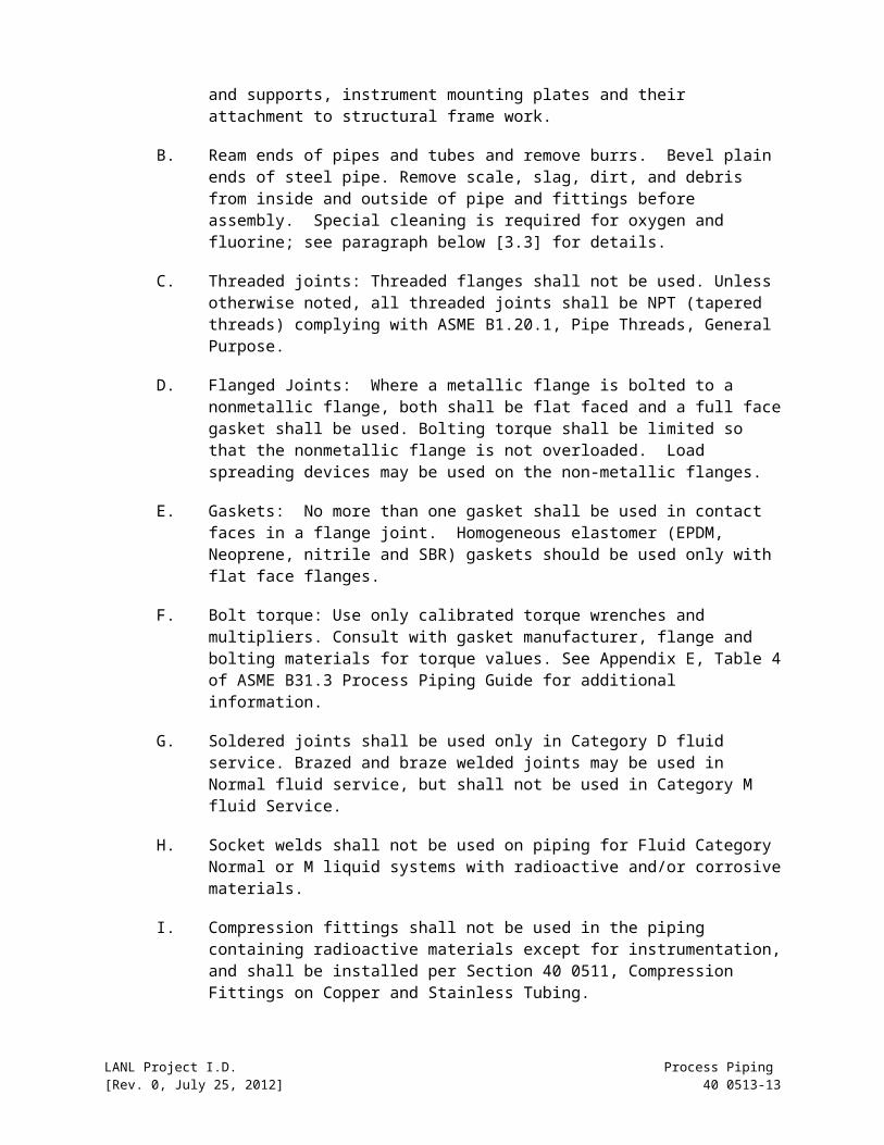
A. Piping and Tubing Systems: Fabricate, inspect, examine, and test in accordance with ASME B31.3. Piping systems include all piping components (including instruments), pipe clamps and supports, instrument mounting plates and their attachment to structural frame work.
B. Ream ends of pipes and tubes and remove burrs. Bevel plain ends of steel pipe. Remove scale, slag, dirt, and debris from inside and outside of pipe and fittings before assembly. Special cleaning is required for oxygen and fluorine; see paragraph below [3.3] for details.
C. Threaded joints: Threaded flanges shall not be used. Unless otherwise noted, all threaded joints shall be NPT (tapered threads) complying with ASME B1.20.1, Pipe Threads, General Purpose.
D. Flanged Joints: Where a metallic flange is bolted to a nonmetallic flange, both shall be flat faced and a full face gasket shall be used. Bolting torque shall be limited so that the nonmetallic flange is not overloaded. Load spreading devices may be used on the non-metallic flanges.
E. Gaskets: No more than one gasket shall be used in contact faces in a flange joint. Homogeneous elastomer (EPDM, Neoprene, nitrile and SBR) gaskets should be used only with flat face flanges.
F. Bolt torque: Use only calibrated torque wrenches and multipliers. Consult with gasket manufacturer, flange and bolting materials for torque values. See Appendix E, Table 4 of ASME B31.3 Process Piping Guide for additional information.
G. Soldered joints shall be used only in Category D fluid service. Brazed and braze welded joints may be used in Normal fluid service, but shall not be used in Category M fluid Service.
H. Socket welds shall not be used on piping for Fluid Category Normal or M liquid systems with radioactive and/or corrosive materials.
I. Compression fittings shall not be used in the piping containing radioactive materials except for instrumentation, and shall be installed per Section 40 0511, Compression Fittings on Copper and Stainless Tubing.
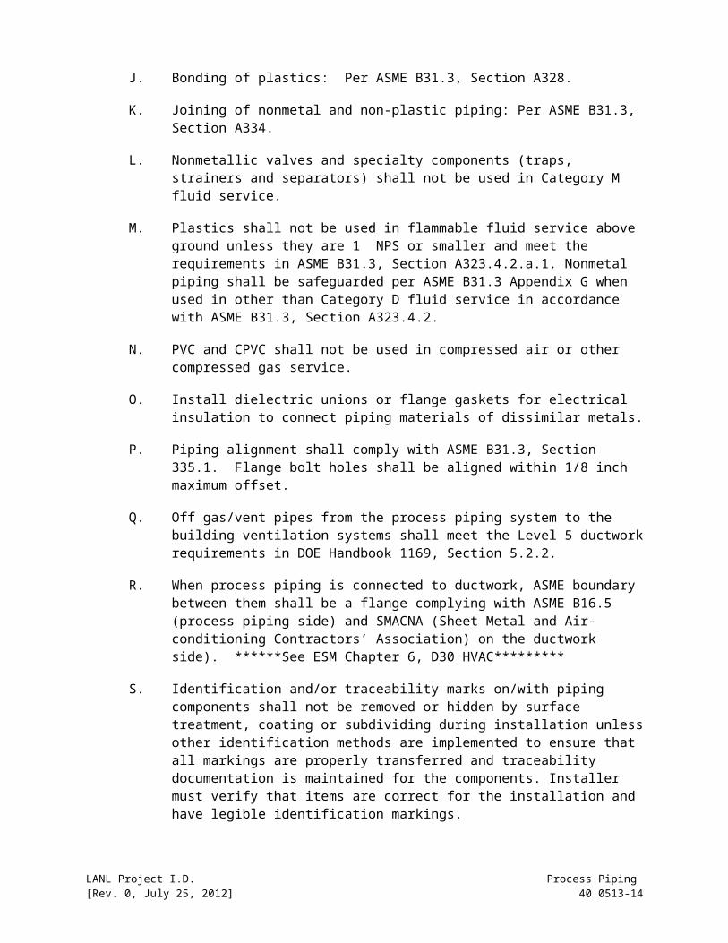
J. Bonding of plastics: Per ASME B31.3, Section A328.
K. Joining of nonmetal and non-plastic piping: Per ASME B31.3, Section A334.
L. Nonmetallic valves and specialty components (traps, strainers and separators) shall not be used in Category M fluid service.
M. Plastics shall not be used in flammable fluid service above ground unless they are 1” NPS or smaller and meet the requirements in ASME B31.3, Section A323.4.2.a.1. Nonmetal piping shall be safeguarded per ASME B31.3
LANL Project I.D. Process Piping [Rev. 0, July 25, 2012] 40 0513-10

Appendix G when used in other than Category D fluid service in accordance with ASME B31.3, Section A323.4.2.
N. PVC and CPVC shall not be used in compressed air or other compressed gas service.
O. Install dielectric unions or flange gaskets for electrical insulation to connect piping materials of dissimilar metals.
P. Piping alignment shall comply with ASME B31.3, Section 335.1. Flange bolt holes shall be aligned within 1/8 inch maximum offset.
Q. Off gas/vent pipes from the process piping system to the building ventilation systems shall meet the Level 5 ductwork requirements in DOE Handbook 1169, Section 5.2.2.
R. When process piping is connected to ductwork, ASME boundary between them shall be a flange complying with ASME B16.5 (process piping side) and SMACNA (Sheet Metal and Air-conditioning Contractors’ Association) on the ductwork side). ******See ESM Chapter 6, D30 HVAC*********
S. Identification and/or traceability marks on/with piping components shall not be removed or hidden by surface treatment, coating or subdividing during installation unless other identification methods are implemented to ensure that all markings are properly transferred and traceability documentation is maintained for the components. Installer must verify that items are correct for the installation and have legible identification markings.
3.3 EXAMINATION, INSPECTION, AND TESTING
A. All fluid categories (M, Normal, and D)
1. LANL will act for DOE to authorize/provide Owners inspectors or representatives (owner inspectors will be qualified by CM-CE).
2. For the purposes of this Section, Subcontractor (constructor) is responsible for all tasks identified as examination, inspection, and testing. At LANLs discretion, LANL inspectors may serve as both the manufacturer/fabricator examiner and owners inspector.
3. Visual examination:
a) Perform in accordance with ASME B31.3, Section 344.2. Acceptance criteria are as stated in ASME B31.3, Section 341.3.2 and in Table 341.3.2 for Category Normal, M and D Fluid Service. Comply with ASME B31.3, Section 341.4 (Normal and D Fluid Service) and Section M341.4 (M Fluid Service) for the scope of visual examination for each fluid category.
b) For bonding of plastics, perform in accordance with ASME B31.3, Section A341.4.1. Acceptance criteria for bonds (plastics) are as stated in ASME B31.3, Section A341.3.2 and in Table A341.3.2.
LANL Project I.D. Process Piping [Rev. 0, July 25, 2012] 40 0513-11

b) Liquid penetrant examination: Perform in accordance with BPV, Section V, Article 6 and ASME B31.3 Section 344.4. See ESM Chapter 13, Volume 6.
c) It is permissible to omit leak testing of any existing joints and connections previously tested and with potential to spread contamination. Initial service leak test shall be performed for these connections in accordance with ESM Chapter 17, Pressure Safety, Post Modification /Maintenance Test section (e.g., I.13.C).
d) Pressure Testing:
e) Follow Section 22 0813, Testing of Piping Systems.
B. Category M Fluid Service (in addition to the above Para [3.2.A])
C. Fabrication including threaded, bolted and other mechanical joints shall be 100% visually examined.
D. Perform random radiography of welds selected by LANL (at least 20% of circumferential butt and miter welds and of fabricated lap and branch connection welds) in accordance with ASME B31.3, Section 344.5 or random ultrasonic examination in accordance with ASME B31.3, Section 344.6.
It is acceptable to substitute in-process inspection for radiography on a weld for weld basis where facility constraints preclude radiography. Perform in-process examination of at least 20% of welded joints using personnel other than those performing the work. It shall be supplemented by appropriate NDE examination specified by the engineering design or by the inspector. For bonding of plastics, perform in process examination of at least 5% of all bonded joints and to ensure that the work of each bonder and bonding operator making the joints is examined. See ESM Chapter 17, Pressure Safety (e.g., Section I.13.A.7) for details.
PART 4 Sensitive Leak testing: Perform a helium leak test to fulfill the sensitive leak test requirement in ASME B31.3, Section 345.8. Perform helium leak test in accordance with ASTM E498 or ASTM E499 with the following test pressures and acceptable leak rates.
Test Pressure: (the lesser of 15 psig or 25% of the design pressure) psig Maximum leakage: (less than 10-3 ) cc/sec.
A. Normal Fluid Service (In addition to the paragraph above on all services [3.2.A])
B. Perform random radiography of welds selected by LANL (not less than 5% of butt and miter groove) in accordance with ASME B31.3, Section 344.5 or random ultrasonic examination in accordance with ASME B31.3, Section 344.6.
It is acceptable to substitute in-process inspection for radiography where facility constraints preclude radiography. Perform in-process examination
LANL Project I.D. Process Piping [Rev. 0, July 25, 2012] 40 0513-12
of at least 5% of welded joints using personnel other than those performing the work. For bonding of plastics, perform in-process examination of at least 5% of all bonded joints and to ensure that the work of each bonder and bonding operator making the joints is examined. See ESM Chapter 17, Pressure Safety (e.g., Section I.13.A.7) for details.
C. Certification and Records
D. Certificates of conformance shall be examined. The examiner shall provide the inspector with a certification that all the quality control requirements of the code and of the engineering design have been carried out.
4.2 CLEANING
A. Subcontractor shall be responsible for the cleanliness integrity of the system. Pipe, tube, and components shall be free of dirt, paint, metal chips, filings, flux, slag, weld spatter, scale, rust, grease, oil, waxes, or other contaminants that are easily seen with the unaided eye.
B. The use of acids and cleaning agents may damage polymer components, such as gaskets, seals, flexible tubing, etc. Consult supplier for chemical resistance of the component before use. The use of mineral acids and organic acids to clean austenitic stainless steel and nickel alloys shall be approved prior to use.
C. Ensure safeguards are taken to protect personnel from hazards of cleaning, which may include but not be limited to flying particulates, corrosive chemicals, and harmful vapors.
D. Weld joint areas and welds shall be pre-cleaned and post-cleaned by wire brushing and scrubbing with a solvent-moistened clean cloth unless otherwise specified.
E. Water flushing shall not be performed for systems designed for pneumatic testing only. Clean water having less than 250 ppm chlorine content shall be used for stainless steel systems. Pockets and dead legs shall be thoroughly flushed, and drained and dried upon completion of flushing.
F. Breathing air systems or strong oxidizer fluid service (oxygen or fluorine) system cleaning shall be performed in accordance with CGA (Compressed Gas Association) pamphlet G-4.1, Cleaning Equipment for Oxygen service. A minimum cleanliness level of 175A per ASTM G93 is required. See ESM Chapter 17, Pressure Safety, Oxygen and Oxidizing Media Components Cleanliness Section (I.12.P) requirements for details.
G. For nuclear systems, Cleaning Methods and Inspection Criteria shall be in accordance with NQA-1 Subpart II and ASTM A380 for stainless steel, and approved cleaning and flushing procedures. At a minimum, Class C cleanness is required for carbon and low alloy steels. Class B cleanness is required for corrosion resistant alloys (stainless steel, nickel-base or cobalt-base alloys). Subcontractor shall submit cleaning procedures for approval.
LANL Project I.D. Process Piping [Rev. 0, July 25, 2012] 40 0513-13
END OF SECTION
*********************************************************Do not delete the following reference information:*********************************************************
FOR LANL USE ONLY
This project specification is based on LANL Master Specification 40 0513 Rev. 0, dated July 25, 2012.
LANL Project I.D. Process Piping [Rev. 0, July 25, 2012] 40 0513-14

Appendix A
*************************************************************************************************************This appendix includes a collection of typical piping specifications used at LANL. These specifications are not designed for specific projects, and only applicable specification(s) should be selected and modified as necessary to meet the specific project requirements. Components in this appendix are either listed components in ASME B31.3 or unlisted components with justification per ASME B31.3, Section 302.2.3.
Piping, fittings and ball valves are listed for example. The engineer must specify all required components (other valves and special components) in this Appendix or in Part 2 (Products) of this section.
Piping specification tables are based on Savannah River Site calculation No., 00-00-CALC-M-0004-R0, Rev 0. See all applicable notes in ESM Chapter 17, Pressure Safety, D20-B31.3-G, ASME B 31.3. Process Piping Guide.*************************************************************************************************************
LANL Project I.D. Process Piping [Rev. 0, July 25, 2012] 40 0513-15

Dry and Wet Vacuum, and Glovebox Purge/Dry Piping
Piping Specification 203 Date: May 8, 2023 Revision: 0 Page 1 of 2
DESIGN PARAMETERSP-Spec PS-203(A, B, C, D)
Design Pressure (psig) 600 505 455 415 380 360 350 Code of Reference: B31.3 - 2002
Design Temperature (F) 100 200 300 400 500 600 650 Fluid Service: Normal
Minimum Temperature (F) -425
-425
-425
-425
-425
-425
-425
Material: Stainless Steel (304L/316L)
Minimum Test Pressure (psig)
900 760 680 670 660 670 665 Pressure Rating: Class 300
Maximum Test Pressure (psig)
935 External Pressure Rating:
15 psi
GENERAL NOTESRefer to General Notes 1-12, 16 in ASME B31.3 Process Piping Guide.
ALLOWABLE PIPE MATERIALSComponent Size Rating Standard Material Material
GradeAdditional Requirements
Piping ¼ - 12 Schedule Tables
ASME B36.19
ASTM A312 304L/316L Seamless
REQUIRED SCHEDULES P-Spec Corrosion
Allowance Pipe Size ¼ ½ ¾ 1 1 ½ 2 2 ½ 3 4 6
A 0.00 Schedule 40S 40S 40S 40S 40S 40S 40S 40S 40S 40S
B 0.03 Schedule 80S 80S 80S 80S 80S 80S 80S 80S 80S 80S
C 0.05 Schedule - 80S 80S 80S 80S 80S 80S 80S 80S 80S
D 0.08 Schedule - - - - - - - 80S 80S 80S
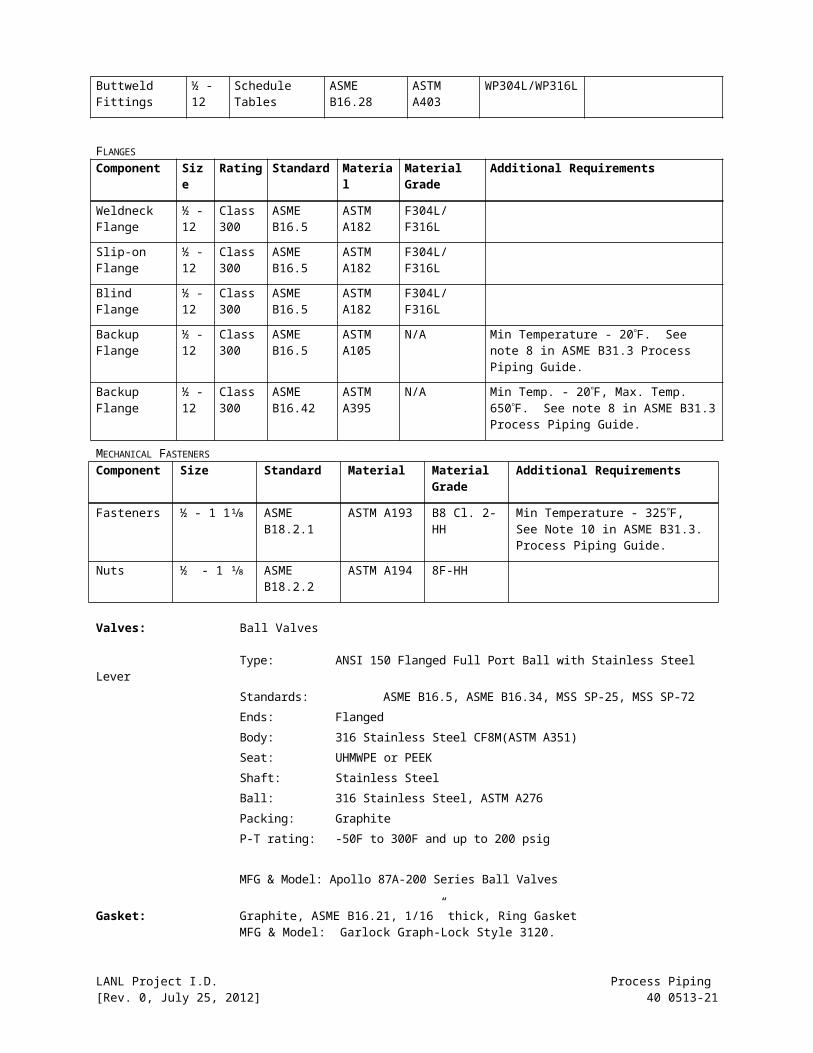
FITTINGSComponent Size Rating Standard Material Material Grade Additional
Requirements
Buttweld Fittings
½ - 12
Schedule Tables
ASME B16.9 ASTM A403
WP304L/WP316L
Buttweld Fittings
½ - 12
Schedule Tables
ASME B16.28
ASTM A403
WP304L/WP316L
FLANGESComponent Size Rating Standard Material Material
GradeAdditional Requirements
Weldneck Flange
½ - 12
Class 300
ASME B16.5
ASTM A182
F304L/F316L
Slip-on Flange
½ - 12
Class 300
ASME B16.5
ASTM A182
F304L/F316L
LANL Project I.D. Process Piping [Rev. 0, July 25, 2012] 40 0513-16

Blind Flange ½ - 12
Class 300
ASME B16.5
ASTM A182
F304L/F316L
Backup Flange
½ - 12
Class 300
ASME B16.5
ASTM A105
N/A Min Temperature - 20F. See note 8 in ASME B31.3 Process Piping Guide.
Backup Flange
½ - 12
Class 300
ASME B16.42
ASTM A395
N/A Min Temp. - 20F, Max. Temp. 650F. See note 8 in ASME B31.3 Process Piping Guide.
MECHANICAL FASTENERSComponent Size Standard Material Material
GradeAdditional Requirements
Fasteners ½ - 1 1⅛ ASME B18.2.1
ASTM A193 B8 Cl. 2-HH Min Temperature - 325F, See Note 10 in ASME B31.3. Process Piping Guide.
Nuts ½ - 1 ⅛ ASME B18.2.2
ASTM A194 8F-HH
Valves: Ball Valves
Type: ANSI 150 Flanged Full Port Ball with Stainless Steel LeverStandards: ASME B16.5, ASME B16.34, MSS SP-25, MSS SP-72Ends: FlangedBody: 316 Stainless Steel CF8M(ASTM A351)Seat: UHMWPE or PEEKShaft: Stainless SteelBall: 316 Stainless Steel, ASTM A276Packing: GraphiteP-T rating: -50F to 300F and up to 200 psig
MFG & Model: Apollo 87A-200 Series Ball Valves
Gasket: Graphite, ASME B16.21, 1/16” thick, Ring Gasket MFG & Model: Garlock Graph-Lock Style 3120.
LANL Project I.D. Process Piping [Rev. 0, July 25, 2012] 40 0513-17

Nitrogen, Argon, Helium, P-10, Regen Gas Tubing (2” or smaller): Stainless Steel
Piping Specification 206 Date: May 8, 2023 Revision: 0 Page 1 of 1
DESIGN PARAMETERSP-Spec PS-206(A, B)
Design Pressure (psig) 600 600 565 500 465 425 280 Code of Reference: B31.3 - 2002
Design Temperature (F) 100 300 400 600 800 900 1000 Fluid Service: Normal
Minimum Temperature (F) -425 -425 -425 -425 -425 -425 -425 Material: Stainless Steel (304L/316L)
Minimum Test Pressure (psig) 900 900 915 930 940 900 625 Pressure Rating: 600 psi
Maximum Test Pressure (psig) 1780 External Pressure
Rating: 15 psi
GENERAL NOTESRefer to General Notes 1-9, 16-18 in ASME B31.3 Process Piping Guide.
ALLOWABLE TUBE MATERIALSComponent Size Rating Standard Material Material
GradeAdditional Requirements
Tubing 1/16 - 2 Schedule Tables ASTM A269 ASTM A269 TP 304L/ 316L CMTR must specify tensile and yield properties.
Tubing 1/16 - 2 Schedule Tables ASTM A249 ASTM A249 TP304L/ 316L
REQUIRED THICKNESS FOR TUBE IN GAS SERVICE:P-
SpecCorrosion Allowance Pipe Size 1/8
3/16 ¼ 5/163/8 ½ 5/8 ¾ 7/8 1 1 ¼ 1 ½ 2
A 0.00 Thickness 0.028 0.028 0.028 0.035 0.035 0.041 0.052 0.062 0.073 0.083 0.104 0.125 0.167
Bend Radius 1.5D 1.5D 1.5D 1.5D 1.5D 1.5D 1.5D 1.5D 1.5D 1.5D 1.5D 1.5D 1.5D
B 0.01 Thickness 0.028 0.028 0.028 0.035 0.035 0.049 0.052 0.062 0.073 0.083 0.104 0.125 0.167
Bend Radius 1.5D 1.5D 1.5D 1.5D 1.5D 1.5D 1.5D 1.5D 1.5D 1.5D 1.5D 1.5D 1.5D
REQUIRED THICKNESS FOR TUBE IN ALL OTHER SERVICES:P-
SpecCorrosion Allowance Pipe Size 1/16
1/83/16 ¼ 5/16
3/8 ½ 5/8 ¾ 7/8 1 1 ¼ 1 ½ 2
A 0.00 Thickness 0.010 0.0280.0280.0280.0350.0350.0350.0490.0490.0490.0650.0950.0950.109
Bend Radius 1.5D 1.5D 1.5D 1.5D 1.5D 1.5D 1.5D 1.5D 1.5D 1.5D 1.5D 1.5D 1.5D 1.5D
B 0.01 Thickness 0.020 0.0280.0280.0350.0350.0350.0490.0490.0490.0650.0650.0950.0950.109
Bend Radius 3D 1.5D 1.5D 1.5D 1.5D 1.5D 1.5D 1.5D 1.5D 1.5D 1.5D 1.5D 1.5D 1.5D
FITTINGSComponent Size Rating Standard Material Material Grade Additional
Requirements
Tube Fittings 1/16 - 2 Manufacturer’s
Manufacturer’s
ASTM A182/A479
316L/304L Swagelok/Cajon or Parker
Welded Fittings 1/16 - 2 Manufacturer’s
Manufacturer’s
ASTM A182/A479
316L/304L Swagelok/Cajon or Parker
LANL Project I.D. Process Piping [Rev. 0, July 25, 2012] 40 0513-18
Valves: Ball Valves
Type: Three piece ball valve, with stainless steel handleStandards: ASME B1.20.1(NPT)/ASME B16.11(Socket Weld)Ends: NPT, Compression Fitting, Tube Socket WeldedBody: 316 Stainless Steel/ASTM A479 or CF3M(A351)Seat: RPTFEShaft: Stainless SteelBall: 316 Stainless Steel/ASTM A276 or A479Packing: RPTFEP-T rating: -20F to 150F, 1200 psig at 150F
MFG & Model: Swagelok 60 series ball valves
LANL Project I.D. Process Piping [Rev. 0, July 25, 2012] 40 0513-19

Nitrogen, Argon, Helium, P-10, Regen Gas Piping: Stainless Steel
Piping Specification 203 Date: May 8, 2023 Revision: 0 Page 1 of 2
DESIGN PARAMETERSP-Spec PS-203(A, B, C, D)
Design Pressure (psig) 600 505 455 415 380 360 350 Code of Reference: B31.3 - 2002
Design Temperature (F) 100 200 300 400 500 600 650 Fluid Service: Normal
Minimum Temperature (F) -425
-425
-425
-425
-425
-425
-425
Material: Stainless Steel (304L/316L)
Minimum Test Pressure (psig)
900 760 680 670 660 670 665 Pressure Rating: Class 300
Maximum Test Pressure (psig)
935 External Pressure Rating:
15 psi
GENERAL NOTESRefer to General Notes 1-12, 16 in ASME B31.3 Process Piping Guide.
ALLOWABLE PIPE MATERIALSComponent Size Rating Standard Material Material
GradeAdditional Requirements
Piping ¼ - 12
Schedule Tables
ASME B36.19
ASTM A312
304L/316L Seamless
REQUIRED SCHEDULES P-
SpecCorrosion Allowance Pipe Size ¼ ½ ¾ 1 1 ½ 2 2 ½ 3 4 6
A 0.00 Schedule 40S 40S 40S 40S 40S 40S 40S 40S 40S 40S
B 0.03 Schedule 80S 80S 80S 80S 80S 80S 80S 80S 80S 80S
C 0.05 Schedule - 80S 80S 80S 80S 80S 80S 80S 80S 80S
D 0.08 Schedule - - - - - - - 80S 80S 80S
FITTINGSComponent Size Rating Standard Material Material
GradeAdditional Requirements
Socket-Weld Fittings
¼ - 2 3000# ASME B16.11
ASTM A182
F304L/316L
Threaded Fittings ¼ - 4 2000# ASME B16.11
ASTM A182
F304L/316L
Buttweld Fittings ½ - 12
Schedule Tables
ASME B16.9 ASTM A403
WP304L/316L
Buttweld Fittings ½ - 12
Schedule Tables
ASME B16.28
ASTM A403
WP304L/316L
FLANGESComponent Size Rating Standard Material Material
GradeAdditional Requirements
Socket-Weld Flange
½ - 12 Class 300 ASME B16.5
ASTM A182
F304L/316L
LANL Project I.D. Process Piping [Rev. 0, July 25, 2012] 40 0513-20
Weldneck Flange ½ - 12 Class 300 ASME B16.5
ASTM A182
F304L/316L
Slip-on Flange ½ - 12 Class 300 ASME B16.5
ASTM A182
F304L/316L
Blind Flange ½ - 12 Class 300 ASME B16.5
ASTM A182
F304L/316L
Threaded Flange ½ - 6 Class 300 ASME B16.5
ASTM A182
F304L/316L
Backup Flange ½ - 12 Class 300 ASME B16.5
ASTM A105
N/A Min Temperature - 20F. See note 8 in ASME B31.3 Process Piping Guide.
Backup Flange ½ - 12 Class 300 ASME B16.42
ASTM A395
N/A Min Temp. - 20F, Max. Temp. 650F. See note 8 in ASME B31.3 Process Piping Guide.
MECHANICAL FASTENERSComponent Size Standard Material Material
GradeAdditional Requirements
Fasteners ½ - 1 1⅛ ASME B18.2.1
ASTM A193 B8 Cl. 2-HH Min Temperature - 325F, See Note 10 in ASME B31.3 Process Piping Guide.
Nuts ½ - 1 ⅛ ASME B18.2.2
ASTM A194 8F-HH
Valves: Ball Valves
Type: Three piece full port ball valve, with stainless steel handleStandards: ASME B16.34, MSS SP-72Ends: Threaded (ASME B1.20.1 NPT), Socket Welded (ASME B16.11), Butt Weld
(MSS SP-72/ASME B16.25) Body: 316 Stainless Steel CF8M(A351)Seat: RPTFEStem: 316 Stainless Steel/ASTM A479Ball: 316 Stainless Steel CF8M(A351)Packing: RPTFEP-T rating: -50F to 200F, 1000 psig for up to 4” and 200 psig for 6” -12”
MFG & Model: FlowTek Model 7000
LANL Project I.D. Process Piping [Rev. 0, July 25, 2012] 40 0513-21

Nitrogen, Argon, Helium, P-10, Regen GasTubing (2” and smaller): Copper
Piping Specification 402 Date: May 8, 2023 Revision: 0 Page 1 of 1
DESIGN PARAMETERSP-Spec PS-402
Design Pressure (psig) 355 300 280 280 275 235 175 Code of Reference: B31.3, 2002
Design Temperature (F) 100 150 200 250 300 350 400 Fluid Service: Normal or Category D
Minimum Temperature (F) -452 -452 -452 -452 -452 -452 -452 Material: Copper
Minimum Test Pressure (psig) 535 530 525 525 525 530 525 Pressure Rating: 355 psi
Maximum Test Pressure (psig) 560 External Pressure
Rating: N/A
GENERAL NOTESRefer to General Notes 1, 3, 5-10, 21, 22, 24-26 in ASME B31.3 Process Piping Guide.
ALLOWABLE TUBE MATERIALSComponent Size Rating Standard Material Material Grade Additional
Requirements
Tubing ¼ - 2 Type L ASTM B88 ASTM B88 Temper 050,060, H
Seamless
REQUIRED SCHEDULES FOR TUBEP-
SpecCorrosion Allowance Pipe Size ¼ ⅜ ½ ⅝ ¾ 1 1 ¼ 1 ½ 2
402 0.00 Thickness 0.030 0.035 0.040 0.042 0.045 0.050 0.055 0.060 0.070
Bend Radius 3D 3D 3D 3D 3D 3D 5D 5D -
FITTINGSComponent Size Rating Standard Material Material
GradeAdditional Requirements
Threaded Fittings
¼ - 2 Class 250 ASME B16.15 AST B62 N/A Max Temperature 350
Soldered Fittings
¼ - 2 Type L ASME B16.18 ASTM B62 N/A Brazed
Soldered Fittings
¼ - 2 Type L ASME B16.22 ASME B16.22 N/A Brazed
Flared Fittings ¼ - 2 500 psig SAE J513 SAE J513 N/A With Flare Nuts, Max Temp 200
Tube Fittings ¼ - 2 Manufacture’s Manufacturer’s Brass per Manufacturer’s
N/A Swagelok/Cajon/ or Parker
MECHANICAL FASTENERSComponent Size Rating Standard Material Material Grade Additional Requirements
Fasteners ½ - ¾ N/A ASME B18.2.1
ASTM A193 B8 Cl. 1- HH Min temperature - 325F, See note 10
Nuts ½ - ¾ N/A ASME B18.2.2
ASTM A194 8F- HH
LANL Project I.D. Process Piping [Rev. 0, July 25, 2012] 40 0513-22

Valves: Ball Valves
2” and smaller Type: Three piece ball valve, with stainless steel handleStandards: ASME B1.20.1(NPT)/ASME B16.11(Socket Weld)Ends: NPT, Compression Fitting, Tube Socket WeldedBody: Brass CDA 360/B16Seat: RPTFEStem: Stainless SteelBall: Brass CDA 360/B16Packing: RPTFEP-T rating: -20F to 150F, 1200 psig at 150F
MFG & Model: Swagelok 60 series ball valves
LANL Project I.D. Process Piping [Rev. 0, July 25, 2012] 40 0513-23

Health Physics Vacuum Piping: Carbon SteelPiping Specification 101 Date: May 8, 2023 Revision: 0 Page 1 of 1Design ParametersP-Spec PS-101(A, B, C, D)Design Pressure (psig) 285 260 230 200 170 140 125 Code of Reference: B31.3 - 2002Design Temperature (F) 100 200 300 400 500 600 650 Fluid Service: Normal or
Category DMinimum Temperature (F)
-20 -20 -20 -20 -20 -20 -20 Material: Carbon Steel
Minimum Test Pressure (psig)
430 390 345 300 270 245 220 Pressure Rating: Class 150
Maximum Test Pressure (psig)
820 External Pressure Rating:
15 psi
General NotesRefer to General Notes 1-12 in ASME B31.3 Process Piping Guide
Allowable Pipe MaterialsComponent Size Rating Standard Material Material
GradeAdditional Requirements
Piping ¼ - 24 Schedule Tables
ASME B36.10M
ASTM A53 B ERW – Type E/Seamless
Piping ¼ - 24 Schedule Tables
ASME B36.10
ASTM A106 B Seamless
Required Schedules P-
SpecCorrosion Allowance Pipe Size ¼ ½ ¾ 1 1 ½ 2 2 ½ 3 4 6
A 0.000 Schedule 80 80 80 80 80 40 40 40 40 40B 0.031 Schedule 80 80 80 80 80 40 40 40 40 40C 0.063 Schedule - 80 80 80 80 80 80 80 40 40D 0.125 Schedule - XXS 160 160 160 160 160 80 80 80
FittingsComponent Size Rating Standard Material Material
GradeAdditional Requirements
Threaded Fittings ¼ - 4 2000#, 3000# ASME B16.11 ASTM A105 WP Use 3000# for PS101-D
Socket-Weld Fittings
¼ - 2 3000#, 6000# ASME B16.11 ASTM A105 WP Use 6000# for PS101-D
Buttweld Fittings ½ - 24 Schedule Tables ASME B16.9 ASTM A234 WPBButtweld Fittings ½ - 24 Schedule Tables ASME B16.28 ASTM A234 WPB
FlangesComponent Size Rating Standard Material Material
GradeAdditional Requirements
Threaded Flange ½ - 6 Class 150 ASME B16.5 ASTM A105 N/ASocket-Weld Flange ½ - 2 Class 150 ASME B16.5 ASTM A105 N/AWeldneck Flange ½ - 24 Class 150 ASME B16.5 ASTM A105 N/ASlip-on Flange ½ - 24 Class 150 ASME B16.5 ASTM A105 N/ABlind Flange ½ - 24 Class 150 ASME B16.5 ASTM A105 N/ABackup Flange ½ - 24 Class 150 ASME B16.5 ASTM A105 N/A
Mechanical FastenersComponent Size Standard Material Material
GradeAdditional Requirements
Fasteners ½ - 1 ¼ ASME B18.2.1 ASTM A193 B7-HH See General Note 10 in ASME B31.3 Process Piping Guide.
Nuts ½ - 1 ¼ ASME B18.2.2 ASTM A194 2H-HH
LANL Project I.D. Process Piping [Rev. 0, July 25, 2012] 40 0513-24

Valves: Ball valves and Butterfly valves
2” and smaller Type: Three piece full port ball valve, with stainless steel handleStandards: ASME B16.34, Class 600Ends: NPT (ASME B1.20.1)Body: Carbon Steel/ASTM A216-WCBSeat: PTFE/RPTFEStem: 316 Stainless Steel/ASTM A276Ball: 316 Stainless Steel/ASTM A276Packing: PTFEP-T rating: -20 to 275F and up to 1,300 psig
MFG. Model: Apollo 83B-140 Ball Valves
2-1/2” and larger Type: Lug Type Butterfly ValveStandards: ASME B16.34, MSS SP-25Ends: Flanged (ASME B16.5 Class 150)Body: Carbon Steel/ASTM A216-WCBSeat: PTFEStem: 17-4 PH Stainless Steel/ASTM A564Disc: 316 Stainless Steel/ASTM A351-CF8MPacking: PTFE P-T rating: 300 psig at 300F
MFG. Model: Keystone K-LOK Figure 362
Gasket: PTFE, ASME B16.21, 1/16” thick, Ring GasketMFG. Model: Garlock Gylon 3510
LANL Project I.D. Process Piping [Rev. 0, July 25, 2012] 40 0513-25

Health Physics Vacuum Tubing (2” and smaller): Copper
Piping Specification 402 Date: May 8, 2023 Revision: 0 Page 1 of 1
DESIGN PARAMETERSP-Spec PS-402
Design Pressure (psig) 355 300 280 280 275 235 175 Code of Reference: B31.3, 2002
Design Temperature (F) 100 150 200 250 300 350 400 Fluid Service: Normal or Category D
Minimum Temperature (F) -452 -452 -452 -452 -452 -452 -452 Material: Copper
Minimum Test Pressure (psig) 535 530 525 525 525 530 525 Pressure Rating: 355 psi
Maximum Test Pressure (psig) 560 External Pressure
Rating: N/A
GENERAL NOTESRefer to General Notes 1, 3, 5-10, 21, 22, 24-26 in ASME B31.3 Process Piping Guide.
ALLOWABLE TUBE MATERIALSComponent Size Rating Standard Material Material Grade Additional
Requirements
Tubing ¼ - 2 Type L ASTM B88 ASTM B88 Temper 050,060, H Seamless
REQUIRED SCHEDULES FOR TUBEP-
SpecCorrosion Allowance Pipe Size ¼ ⅜ ½ ⅝ ¾ 1 1 ¼ 1 ½ 2
402 0.00 Thickness 0.030 0.035 0.040 0.042 0.045 0.050 0.055 0.060 0.070
Bend Radius 3D 3D 3D 3D 3D 3D 5D 5D -
FITTINGSComponent Size Rating Standard Material Material
GradeAdditional Requirements
Threaded Fittings
¼ - 2 Class 250 ASME B16.15
AST B62 N/A Max Temperature 350
Soldered Fittings
¼ - 2 Type L ASME B16.18
ASTM B62 N/A Brazed
Soldered Fittings
¼ - 2 Type L ASME B16.22
ASME B16.22 N/A Brazed
Flared Fittings ¼ - 2 500 psig SAE J513 SAE J513 N/A With Flare Nuts, Max Temp 200
Tube Fittings ¼ - 2 Manufacture’s
Manufacturer’s
Brass per Manufacturer’s
N/A Swagelok/Cajon/ or Parker
MECHANICAL FASTENERSComponent Size Rating Standard Material Material
GradeAdditional Requirements
Fasteners ½ - ¾ N/A ASME B18.2.1
ASTM A193 B8 Cl. 1- HH Min temperature - 325F, See note 10
Nuts ½ - ¾ N/A ASME B18.2.2
ASTM A194 8F- HH
LANL Project I.D. Process Piping [Rev. 0, July 25, 2012] 40 0513-26

Valves: Ball Valves
Type: Three piece ball valve, with stainless steel handleStandards: ASME B1.20.1(NPT)/ASME B16.11(Socket Weld)Ends: NPT, Compression Fitting, Tube Socket WeldedBody: Brass CDA 360/B16Seat: RPTFEStem: Stainless SteelBall: Brass CDA 360/B16Packing: RPTFEP-T rating: -20F to 150F, 1200 psig at 150F
MFG & Model: Swagelok 60 series ball valves
LANL Project I.D. Process Piping [Rev. 0, July 25, 2012] 40 0513-27

Breathing Air:Tubing and components must be cleaned to meet CGA G-4.1 for oxygen service.
Piping Specification 206 Date: May 8, 2023 Revision: 0 Page 1 of 1
DESIGN PARAMETERSP-Spec PS-206(A, B)
Design Pressure (psig) 600 600 565 500 465 425 280 Code of Reference: B31.3 - 2002
Design Temperature (F) 100 300 400 600 800 900 1000 Fluid Service: Normal
Minimum Temperature (F) -425 -425 -425 -425 -425 -425 -425 Material: Stainless Steel (304L/316L)
Minimum Test Pressure (psig) 900 900 915 930 940 900 625 Pressure Rating: 600 psi
Maximum Test Pressure (psig) 1780 External Pressure
Rating: 15 psi
ALLOWABLE TUBE MATERIALSComponent Size Rating Standard Material Material
GradeAdditional Requirements
Tubing 1/16 - 2 Schedule Tables ASTM A269 ASTM A269 TP 304L/316L CMTR must specify tensile and yield properties.
Tubing 1/16 - 2 Schedule Tables ASTM A249 ASTM A249 TP 304L/316L
REQUIRED THICKNESS FOR TUBE IN GAS SERVICE:P-
SpecCorrosion Allowance Pipe Size 1/8
3/16 ¼ 5/163/8 ½ 5/8 ¾ 7/8 1 1 ¼ 1 ½ 2
A 0.00 Thickness 0.028 0.028 0.028 0.035 0.035 0.041 0.052 0.062 0.073 0.083 0.104 0.125 0.167
Bend Radius 1.5D 1.5D 1.5D 1.5D 1.5D 1.5D 1.5D 1.5D 1.5D 1.5D 1.5D 1.5D 1.5D
B 0.01 Thickness 0.028 0.028 0.028 0.035 0.035 0.049 0.052 0.062 0.073 0.083 0.104 0.125 0.167
Bend Radius 1.5D 1.5D 1.5D 1.5D 1.5D 1.5D 1.5D 1.5D 1.5D 1.5D 1.5D 1.5D 1.5D
REQUIRED THICKNESS FOR TUBE IN ALL OTHER SERVICES:P-
SpecCorrosion Allowance
Pipe Size
1/161/8
3/16 ¼ 5/163/8 ½ 5/8 ¾ 7/8 1 1 ¼ 1 ½ 2
A 0.00 Thickness 0.010 0.028 0.028 0.028 0.035 0.035 0.035 0.049 0.049 0.049 0.065 0.095 0.095 0.109
Bend Radius 1.5D 1.5D 1.5D 1.5D 1.5D 1.5D 1.5D 1.5D 1.5D 1.5D 1.5D 1.5D 1.5D 1.5D
B 0.01 Thickness 0.020 0.028 0.028 0.035 0.035 0.035 0.049 0.049 0.049 0.065 0.065 0.095 0.095 0.109
Bend Radius 3D 1.5D 1.5D 1.5D 1.5D 1.5D 1.5D 1.5D 1.5D 1.5D 1.5D 1.5D 1.5D 1.5D
FITTINGSComponent Size Rating Standard Material Material Grade Additional
Requirements
Tube Fittings 1/16 - 2 Manufacturer’s Manufacturer’s ASTM A182/A479
316L/304L Swagelok/Cajon or Parker
Welded Fittings 1/16 - 2 Manufacturer’s Manufacturer’s ASTM A182/A479
316L/304L Swagelok/Cajon or Parker
LANL Project I.D. Process Piping [Rev. 0, July 25, 2012] 40 0513-28

Valves: Ball Valves
Type: Three piece ball valve, with stainless steel handleStandards: ASME B1.20.1(NPT)/ASME B16.11(Socket Weld)Ends: NPT, Compression Fitting, Tube Socket WeldedBody: 316 Stainless Steel/ASTM A479 or CF3M(A351)Seat: PTFEShaft: 316 Stainless Steel/ASTM A276Ball: 316 Stainless Steel/ASTM A276 or A479Packing: PTFEP-T rating: -20F to 150F, 1200 psig at 150F
MFG & Model: Swagelok 60 series ball valves
LANL Project I.D. Process Piping [Rev. 0, July 25, 2012] 40 0513-29

Oxygen:Piping and components must be cleaned to meet CGA G-4.1 for oxygen service.
Piping Specification 201 Date: May 8, 2023 Revision: 0 Page 1 of 1
DESIGN PARAMETERSP-Spec PS-201(A, B, C, D)
Design Pressure (psig) 230 195 175 160 145 140 125 Code of Reference: B31.3 - 2002
Design Temperature (F) 100 200 300 400 500 600 650 Fluid Service: Normal
Minimum Temperature (F)
-425
-425
-425
-425
-425
-425
-425
Material: Stainless Steel (304L/316L)
Minimum Test Pressure (psig)
345 295 265 255 250 255 230 Pressure Rating: Class 150
Maximum Test Pressure (psig)
440 for NPS ≤ 6, 360 for NPS > 6 External Pressure Rating:
15 psi
ALLOWABLE PIPE MATERIALSComponent Size Rating Standard Material Material Grade Additional
Requirements
Piping ¼ - 24 Schedule Tables ASME B36.19 ASTM A312 TP304L/316L Seamless
REQUIRED SCHEDULES P-
SpecCorrosion Allowance Pipe Size ¼ ½ ¾ 1 1 ½ 2 2 ½ 3 4 6
A 0.00 Schedule 40S 40S 40S 40S 40S 40S 40S 40S 40S 40S
B 0.03 Schedule 80S 80S 40S 40S 40S 40S 40S 40S 40S 40S
C 0.05 Schedule 80S 80S 80S 80S 80S 80S 40S 40S 40S 40S
D 0.08 Schedule - - - 80S 80S 80S 80S 80S 80S 40S
FITTINGSComponent Size Rating Standard Material Material Grade Additional
Requirements
Buttweld Fittings
½ - 24 Schedule Tables ASME B16.9 ASTM A403 WP304L/316L
Buttweld Fittings
½ - 24 Schedule Tables ASME B16.28 ASTM A403 WP304L/316L
FLANGESComponent Size Rating Standard Material Material
GradeAdditional Requirements
Socket-Weld Flange
½ - 2 Class 150 ASME B16.5 ASTM A182 F304L/316L
Weldneck Flange ½ - 24 Class 150 ASME B16.5 ASTM A182 F304L/316L
Slip-on Flange ½ - 24 Class 150 ASME B16.5 ASTM A182 F304L/316L
Blind Flange ½ - 24 Class 150 ASME B16.5 ASTM A182 F304L/316L
Backup Flange ½ - 24 Class 150 ASME B16.5 ASTM A105 N/A Min Temperature - 20F. See note 8 in ASME B31.3 Process Piping Guide.
LANL Project I.D. Process Piping [Rev. 0, July 25, 2012] 40 0513-30

Backup Flange ½ - 24 Class 150 ASME B16.42
ASTM A395 N/A Min Temp. - 20F, Max. Temp. 650F. See note 8 in ASME B31.3 Process Piping Guide.
MECHANICAL FASTENERSComponent Size Standard Material Material
GradeAdditional Requirements
Fasteners ½ - 1 ¼ ASME B18.2.1
ASTM A193 B8 Cl. 2-HH Min Temperature - 325F, See Note 10 in ASME B31.3 Process Piping Guide.
Nuts ½ - 1 ¼ ASME B18.2.2
ASTM A194 8F-HH
Valves: Ball valves
2” and smaller Type: Three piece full port ball valve, with stainless steel handle, (Welded) Cleaned for Oxygen Service
Standards: ASME B16.34, Class 600, API 607 & UL 842, Ends: Socket Weld (ASME B16.11)/Butt Weld (ASME B16.25)Body: Stainless Steel CF8M(ASTM A351)Seat: PTFE/RPTFEStem: 316 Stainless Steel/ASTM A276Ball: 316 Stainless Steel/ASTM A276Packing: PTFEP-T rating: -20 to 300F and up to 1,100 psig
MFG. Model: Apollo 83B-200 (Socket Weld) or 83B-500 (Sch 40 Butt Weld)
½” and larger Type: ANSI 150 Flanged Full Port Ball with Stainless Steel Lever,(Flanged) Cleaned for Oxygen Service
Standards: ASME B16.34, API 607 & UL842Ends: FlangedBody: 316 Stainless Steel CF8M(ASTM A351)Seat: PTFE/RPTFEShaft: Stainless SteelBall: 316 Stainless Steel, ASTM A276Packing: GraphiteP-T rating: -50F to 300F and up to 200 psig
MFG & Model: Apollo 87A-200 Series Ball Valves
Gasket: PTFE, ASME B16.21, 1/16” thick, Ring GasketMFG. Model: Garlock Gylon 3510
LANL Project I.D. Process Piping [Rev. 0, July 25, 2012] 40 0513-31

Diesel FuelPiping Specification 101 Date: May 8, 2023 Revision: 0 Page 1 of 1Design ParametersP-Spec PS-101(A, B, C, D)Design Pressure (psig) 285 260 230 200 170 140 125 Code of Reference: B31.3 -
2002Design Temperature (F) 100 200 300 400 500 600 650 Fluid Service: NormalMinimum Temperature (F) -20 -20 -20 -20 -20 -20 -20 Material: Carbon
SteelMinimum Test Pressure (psig)
430 390 345 300 270 245 220 Pressure Rating: Class 150
Maximum Test Pressure (psig)
820 External Pressure Rating:
15 psi
General NotesRefer to General Notes 1-12 in ASME B31.3 Process Piping GuideAllowable Pipe MaterialsComponent Size Rating Standard Material Material
GradeAdditional Requirements
Piping ¼ - 24 Schedule Tables ASME B36.10M ASTM A53 B ERW – Type E/Seamless
Piping ¼ - 24 Schedule Tables ASME B36.10 ASTM A106 B SeamlessRequired Schedules P-Spec Corrosion
Allowance Pipe Size ¼ ½ ¾ 1 1 ½ 2 2 ½ 3 4 6
A 0.000 Schedule 80 80 80 80 80 40 40 40 40 40B 0.031 Schedule 80 80 80 80 80 40 40 40 40 40C 0.063 Schedule - 80 80 80 80 80 80 80 40 40D 0.125 Schedule - XXS 160 160 160 160 160 80 80 80
FittingsComponent Size Rating Standard Material Material
GradeAdditional Requirements
Threaded Fittings ¼ - 4 2000#, 3000#
ASME B16.11
ASTM A105 WP Use 3000# for PS101-D
Socket-Weld Fittings
¼ - 2 3000#, 6000#
ASME B16.11
ASTM A105 WP Use 6000# for PS101-D
Buttweld Fittings ½ - 24 Schedule Tables
ASME B16.9 ASTM A234 WPB
Buttweld Fittings ½ - 24 Schedule Tables
ASME B16.28
ASTM A234 WPB
FlangesComponent Size Rating Standard Material Material
GradeAdditional Requirements
Threaded Flange ½ - 6 Class 150 ASME B16.5 ASTM A105 N/ASocket-Weld Flange
½ - 2 Class 150 ASME B16.5 ASTM A105 N/A
Weldneck Flange ½ - 24 Class 150 ASME B16.5 ASTM A105 N/ASlip-on Flange ½ - 24 Class 150 ASME B16.5 ASTM A105 N/ABlind Flange ½ - 24 Class 150 ASME B16.5 ASTM A105 N/ABackup Flange ½ - 24 Class 150 ASME B16.5 ASTM A105 N/A
Mechanical FastenersComponent Size Standard Material Material
GradeAdditional Requirements
Fasteners ½ - 1 ¼ ASME B18.2.1
ASTM A193 B7-HH See General Note 10.
Nuts ½ - 1 ¼ ASME ASTM A194 2H-HH
LANL Project I.D. Process Piping [Rev. 0, July 25, 2012] 40 0513-32

B18.2.2
Valves: Ball valves
2” and smaller Type: Three Piece Full Port Ball Valve, with stainless steel leverStandards: ASME B16.34, Class 600, API 607 (Fire Safe) & UL 842Ends: NPT (ASME B1.20.1)/Socket Weld (ASME B16.11)/Butt Weld (ASME
B16.25)Body: Carbon Steel/ASTM A216-WCBSeat: PTFE/RPTFEStem: 316 Stainless Steel/ASTM A276Ball: 316 Stainless Steel/ASTM A276Packing: GraphiteP-T rating: -20 to 275F and up to 1,300 psig
MFG. Model: Apollo 83B-140 (NPT), 83B-240(Socket Weld), 83B-540 (Sch. 40 Butt Weld) & 83B-640 (Sch. 80 Butt Weld)
1-1/2” and larger Type: ANSI Flanged Standard Port Ball Valve(Flanged) Standards: ASME B16.34, Class 150, API 607 (Fire Safe) &
UL 842Ends: Flanged (ASME B16.5)Body: Carbon Steel/ASTM A216-WCBSeat: PTFE/RPTFEStem: Carbon Steel/ASTM A108 Type 1215Ball: Carbon Steel/ASTM A108 Type 1215Packing: GraphiteP-T rating: -50F to 325F and 210 psig at 325F.
MFG. Model: Apollo 88A series
Gasket: PTFE, ASME B16.21, 1/16” thick, Ring GasketMFG. Model: Garlock Gylon 3510
Or
Spiral Wound with PTFE filler with surface finish of 125-250 rms, ASME B16.20, 1/16” thick, Ring GasketMFG. Model: Garlock Flexseal RWI
LANL Project I.D. Process Piping [Rev. 0, July 25, 2012] 40 0513-33

Radioactive Liquid Waste, Acids and Caustic WastePiping Specification 201 Date: May 8, 2023 Revision: 0 Page 1 of 1
DESIGN PARAMETERSP-Spec PS-201(A, B, C, D)
Design Pressure (psig) 230 195 175 160 145 140 125 Code of Reference: B31.3 - 2002
Design Temperature (F) 100 200 300 400 500 600 650 Fluid Service: Normal
Minimum Temperature (F) -425
-425
-425
-425
-425
-425
-425
Material: Stainless Steel (316L)
Minimum Test Pressure (psig)
345 295 265 255 250 255 230 Pressure Rating: Class 150
Maximum Test Pressure (psig)
440 for NPS ≤ 6, 360 for NPS > 6 External Pressure Rating:
15 psi
ALLOWABLE PIPE MATERIALSComponent Size Rating Standard Material Material
GradeAdditional Requirements
Piping ¼ - 24 Schedule Tables ASME B36.19 ASTM A312 TP316L Seamless
REQUIRED SCHEDULES P-
SpecCorrosion Allowance Pipe Size ¼ ½ ¾ 1 1 ½ 2 2 ½ 3 4 6
A 0.00 Schedule 40S 40S 40S 40S 40S 40S 40S 40S 40S 40S
B 0.03 Schedule 80S 80S 40S 40S 40S 40S 40S 40S 40S 40S
C 0.05 Schedule 80S 80S 80S 80S 80S 80S 40S 40S 40S 40S
D 0.08 Schedule - - - 80S 80S 80S 80S 80S 80S 40S
FITTINGSComponent Size Rating Standard Material Material
GradeAdditional Requirements
Buttweld Fittings ½ - 24 Schedule Tables
ASME B16.9 ASTM A403 WP316L
Buttweld Fittings ½ - 24 Schedule Tables
ASME B16.28 ASTM A403 WP316L
FLANGESComponent Size Rating Standard Material Material
GradeAdditional Requirements
Weldneck Flange ½ - 24 Class 150 ASME B16.5 ASTM A182 F316L
Slip-on Flange ½ - 24 Class 150 ASME B16.5 ASTM A182 F316L
Blind Flange ½ - 24 Class 150 ASME B16.5 ASTM A182 F316L
Backup Flange ½ - 24 Class 150 ASME B16.5 ASTM A105 N/A Min Temperature - 20F. See note 8 in ASME B31.3 Process Piping Guide.
Backup Flange ½ - 24 Class 150 ASME B16.42
ASTM A395 N/A Min Temp. - 20F, Max. Temp. 650F. See note 8 in ASME B31.3 Process Piping Guide.
LANL Project I.D. Process Piping [Rev. 0, July 25, 2012] 40 0513-34

MECHANICAL FASTENERSComponent Size Standard Material Material
GradeAdditional Requirements
Fasteners ½ - 1 ¼ ASME B18.2.1 ASTM A193 B8 Cl. 2-HH Min Temperature - 325F, See Note 10 in ASME B31.3 Process Piping Guide.
Nuts ½ - 1 ¼ ASME B18.2.2 ASTM A194 8F-HH
Valves: Ball valves
2” and smaller Type: Three piece full port ball valve, with stainless steel handle(Welded) Standards: ASME B16.34, Class 600
Ends: Butt Weld (ASME B16.25)Body: Stainless Steel CF8M(ASTM A351)Seat: PTFE/RPTFEStem: 316 Stainless Steel/ASTM A276Ball: 316 Stainless Steel/ASTM A276Packing: PTFEP-T rating: -20 to 300F and up to 1,100 psigMFG. Model: Apollo 86B-500 (Sch. 40) & 86B-600 (Sch.80)
½” and larger Type: ANSI 150 Flanged Full Port Ball with Stainless Steel Lever(Flanged) Standards: ASME B16.34, MSS SP-25, MSS SP-72
Ends: FlangedBody: 316 Stainless Steel CF8M(ASTM A351)Seat: PTFE/RPTFEShaft: Stainless SteelBall: 316 Stainless Steel, ASTM A276Packing: PTFEP-T rating: -50F to 300F and up to 200 psigMFG & Model: Apollo 87A-200 Series Ball Valves
Gasket (Low Level, Acids, Caustics):PTFE, ASME B16.21, 1/16” thick, Ring GasketMFG. Model: Garlock Gylon 3510OrSpiral Wound with PTFE filler with surface finish of 125-250 rmsB16.20, 1/16” thick, Ring GasketMFG. Model: Garlock Flexseal RWI
Gasket (High Level, TRU)Graphite, ASME B16.21, 1/16” thick, Ring Gasket MFG & Model: Garlock Graph-Lock Style 3120.Graphite, ASME B16.21, 1/16” thick, Ring Gasket MFG & Model: Garlock Graph-Lock Style 3120.
LANL Project I.D. Process Piping [Rev. 0, July 25, 2012] 40 0513-35

Hydrogen Fluoride and Hydrofluoric Acid:
Piping Specification 306 Date: May 8, 2023 Revision: 0 Page 1 of 1
DESIGN PARAMETERSP-Spec PS-306(A, B, C) Calculation
Reference:00-00-CALC-M-0004-R0
Design Pressure (psig) 230 200 190 185 170 140 125 Code of Reference: B31.3, 2002
Design Temperature (F)
100 200 300 400 500 600 650 Fluid Service: Normal
Minimum Temperature (F)
-325
-325
-325
-325
-325
-325
-325
Material: Monel (N04400)
Minimum Test Pressure (psig)
360 335 330 320 295 245 225 Pressure Rating: Class 150
Maximum Test Pressure (psig)
395 External Pressure Rating:
15 psi
GENERAL NOTESRefer to General Notes 1-12, 16.
ALLOWABLE PIPE MATERIALSComponent
Size Rating Standard Material Material Grade
Additional Requirements
Piping ¼ - 8 Schedule Tables
ASTM B165
N04400 N/A Seamless
REQUIRED SCHEDULES P-
SpecCorrosion Allowance Pipe Size ¼ ½ ¾ 1 1 ½ 2 2 ½ 3 4 6
A 0.00 Schedule 40S 40S 40S 40S 40S 40S 40S 40S 40S 40S
B 0.03 Schedule 80S 40S 40S 40S 40S 40S 40S 40S 40S 40S
C 0.05 Schedule 80S 80S 80S 80S 80S 80S 40S 40S 40S 40S
FITTINGSComponent Size Rating Standard Material Material
GradeAdditional Requirements
Threaded Fittings ¼ - 6 2000# ASME B16.11
B564 N04400 Engineering approval required
Buttweld Fittings ½ - 8 Schedule Tables
ASME B16.9
B366 WPNC Seamless or welded
Buttweld Fittings ½ - 8 Schedule Tables
ASME B16.28
B366 WPNC
FLANGESComponent Size Rating Standard Material Material
GradeAdditional Requirements
Weldneck Flange ½ - 8 Class 150 ASME B16.5
B564/B127
N04400
Blind Flange ½ - 8 Class 150 ASME B16.5
B564/B127
N04400
Backup Flange ½ - 8 Class 150 ASME B16.5
A105 N/A
LANL Project I.D. Process Piping [Rev. 0, July 25, 2012] 40 0513-36

MECHANICAL FASTENERSComponent Size Standard Material Material
GradeAdditional Requirements
Fasteners ½ - ¾ ASME B18.2.1
ASTM A193 B8 C1.2-HH Refer to General Note 10 in ASME B 31.3 process Piping Guide
Nuts ½ - ¾ ASME B18.2.2
ASTM A194 8F-HH
Valves: Ball Valves
Type: Split body, Full Port, Floating Ball ValveStandards: ASME B16.10, ASME B16.34, Class 150, API 6D,
API 607 (Fire Safe)Ends: FlangedBody: MonelSeat: PTFEStem: MonelBall: MonelPacking: PTFEP-T rating: 0F to 300F and up to 285 psig
MFG. Model: KTM (Tyco) EP100
Gasket: PTFE with graphite filler, ASME B16.21, 1/16” thick, Ring Gasket
MFG. Model: Garlock Gylon 3530
End of Examples*******************************************************************
LANL Project I.D. Process Piping [Rev. 0, July 25, 2012] 40 0513-37