section 4 host link communications - universidade...
TRANSCRIPT

33
SECTION 4Host Link Communications
This section describes the procedure and other information required to use Host Link communications.
4-1 Host Link Communications . . . . . . . . . . . . . . . . . . . . . . . . . . . . . . . . . . . . . . . . . . . . . . . . . 4-1-1 Host Link Communications . . . . . . . . . . . . . . . . . . . . . . . . . . . . . . . . . . . . . . . . . . 4-1-2 Host Link Specifications . . . . . . . . . . . . . . . . . . . . . . . . . . . . . . . . . . . . . . . . . . . .
4-2 Application Procedure . . . . . . . . . . . . . . . . . . . . . . . . . . . . . . . . . . . . . . . . . . . . . . . . . . . . . 4-3 Connections . . . . . . . . . . . . . . . . . . . . . . . . . . . . . . . . . . . . . . . . . . . . . . . . . . . . . . . . . . . . .
4-3-1 Types of Connection . . . . . . . . . . . . . . . . . . . . . . . . . . . . . . . . . . . . . . . . . . . . . . . 4-3-2 Standard Cables from Board to Personal Computer . . . . . . . . . . . . . . . . . . . . . . .
4-4 Host Link Communications . . . . . . . . . . . . . . . . . . . . . . . . . . . . . . . . . . . . . . . . . . . . . . . . . 4-4-1 Protocol . . . . . . . . . . . . . . . . . . . . . . . . . . . . . . . . . . . . . . . . . . . . . . . . . . . . . . . . . 4-4-2 Example Programs . . . . . . . . . . . . . . . . . . . . . . . . . . . . . . . . . . . . . . . . . . . . . . . . . 4-4-3 Host Link Commands . . . . . . . . . . . . . . . . . . . . . . . . . . . . . . . . . . . . . . . . . . . . . . 4-4-4 End Codes . . . . . . . . . . . . . . . . . . . . . . . . . . . . . . . . . . . . . . . . . . . . . . . . . . . . . . .
4-5 Changes from Previous Products . . . . . . . . . . . . . . . . . . . . . . . . . . . . . . . . . . . . . . . . . . . . . 4-5-1 RS-232C Ports . . . . . . . . . . . . . . . . . . . . . . . . . . . . . . . . . . . . . . . . . . . . . . . . . . . . 4-5-2 RS-422A/485 Ports . . . . . . . . . . . . . . . . . . . . . . . . . . . . . . . . . . . . . . . . . . . . . . . .

4-1SectionHost Link Communications
34
4-1 Host Link CommunicationsA Host Link System can be used to send C-mode Host Link commands from ahost (e.g., personal computer or PT) to a PC to read/write I/O memory, controloperating modes, etc. The PC can also use the TXD(––) instruction to send spe-cified I/O memory data to the host for slave-initiated communications.
Refer to the CQM1H-series PC Programming Manual for details on C-modecommands.
Communications in a Host Link System are normally started by a host computer.
Host computer CQM1H-series PCCommand
Response
The host sends a command to the PC. The PC processes the command and re-turns a response to the host computer. This process is repeated, allowing thehost computer to monitor and control PC operation.
The PC can also initiate communications with the host to send data, as may benecessary when errors occur on the line controlled by the PC or to confirm theoperating status of the host.
Host computer CQM1H-series PCASCII data
When the TXD(––) instruction is executed in the ladder program of the PC, thecontents of the I/O memory words specified for the instruction is converted toASCII and sent to the host. There is no response to this transmission.
TXD(––) InstructionTXD(48) reads N bytes of data beginning from words S, converts it to ASCII, andoutputs the data from the specified port as a Host Link command. Up to 122 by-tes (61 words) of data can be sent. Refer to the CQM1H-series PC ProgrammingManual for details.
TXD(48)
S
C
N
First source word
Control word
Number of bytes: 4 digits BCD, 0000 to 0061
The format of the Host Link command generated by TXD(––) is shown below.The command header code is EX and is followed by the specified data con-verted to ASCII. There is no response to the EX command.
@ E Xx 100x 101 ↵�
Node No. Headercode
122 characters max. TerminatorFCS
Send data (ASCII)
Note If the PC is sending a response to a Host Link command when the TXD(––) in-struction is executed, the EX command for TXD(––) will be sent after the re-sponse.
If TXD(––) is executed in Host Link Mode, the specified data is converted toASCII before being sent. If TXD(––) is executed in No-protocol Mode, the speci-fied data is sent without conversion.
Host-initiatedCommunications
Slave-initiatedCommunications

4-1SectionHost Link Communications
35
4-1-1 Host Link CommunicationsHost Link communications are supported by all CQM1H-series CPU Units. ASerial Communications Board can be used to connect a single PC to more thanone host computer for Host Link communications, including slave-initiated com-munications. Host Link communications provide the following features.
An RS-422A/485 port can be used to connect one host computer to up to 32CQM1H-series PCs.
Host Link communications enable the host computer to monitor or control PCoperations and to read and write I/O memory in the PCs.
Both vertical and horizontal (FCS) parity checks are performed on communica-tions data to achieve essentially error-free communications. Combining errorchecking and retry processing goes one step further to eliminate nearly all theeffects of communications problems.
The Serial Communications Board provides two serial communications portsthat can be used simultaneously to connect to two different networks of hostcomputers in addition to the connections made directly from the built-in CPUUnit ports.
Communications can be performed either by sending a command from a hostand having the PC return a response, or by sending data from a PC to the host.
Note A Host Link connection can also be used to connect the PC to a ProgrammingDevice running on a personal computer. The following two modes can be used toconnect to computers running Programming Devices. Only the Host Link Modecan be used for the Serial Communications Board.
Serial communicationsmode
Features
Host Link Functions as a communications protocol with standardhost computers.
Either 1:1 or 1:N connections are possible.
Slower than a peripheral bus connection.
Connection is possible through a modem or Optical LinkAdapter, and long-distance and 1:N connections arepossible using RS-422A/485.
Peripheral bus Enables high-speed communications. A peripheral busconnection is thus the normal mode used to connect to acomputer running the CX-Programmer.
Only 1:1 connections are possible.
With the CQM1H, the baud rate of the ProgrammingDevice is detected when the connection is made.
Connect One Computerto Multiple PCs
Computer Monitoringand Control of PCs
Redundant ErrorChecking
Simultaneous Usage ofBoth Ports
Slave-initiatedCommunications

4-2SectionApplication Procedure
36
4-1-2 Host Link Specifications
Item Description
Communications mode Half-duplex (Full-duplex for slave-initiated communications)
Synchronization Start-stop (asynchronous mode)
Baud rate (see note 1) RS-232C port and RS-422A/485 ports:1,200/2,400/4,800/9,600/19,200 bps
Default setting: 9,600 bps
Communicationsdistance (see note 1)
RS-232C port: 15 m max. (see note 2)
RS-442A/485 port: 500 m max. (The total combined cable length is 500 m max. T-branchlines must be a maximum of 10 m long.)
Connectionconfiguration
RS-232C port: 1:1 (1:N (N = 32 Units max.) is possible using an Converting Link Adapters.)
RS-422A/485 port: 1:N (N = 32 Units max.)
Number of connectedUnits
32 Units max. (unit numbers 0 to 31; unit number 0 is set for 1:1 connection)
Frame structure C-mode Host Link commands
Header: @, address: (Host Link unit number) 0 to 31 (BCD)Data: Header code + textError check code: FCSTerminator: *+CR
Error check codes Vertical parity: Even, odd. or none FCS (horizontal parity converted to ASCII)
Command flow and Command flow Commands Contentssupport Host computer to
PCC-mode Host Linkcommands
1:1 or 1:N communications with directly connectedPCs (The specified frame format must be preparedon the host computer and then sent.)
PC to hostcomputer
Data only Communications using TXD(––) from CPU Unit.
No response from host.
Connection between the host computer and PCmust be 1:1.
Transmission delaytime
Host computer to PC
The delay is from the return of aresponse by the PC until a responsecan be returned to the next commandreceived from the host.
0 to 99,990 ms (set in PC Setup in 10-ms units)
PC to host computer
The delay is from the beginning ofTXD(––) execution until execution ofthe next TXD(––) can be started.
Note 1. Confirm the baud rates and communications distance supported by con-nected devices.
2. The maximum cable length for RS-232C is 15 m.
4-2 Application Procedure1, 2, 3... 1. Turn OFF the power supply to the PC.
2. Mount the Board.
3. Connections
Connect the external devices using RS-232C or RS-422 cables. The TERMand WIRE switches on the front panel of the Board must be set if the Board isconnected using the RS-4522A/485 port.
The host computer can be connected to a PC 1:1, or NT-AL001-E Convert-ing Link Adapters can be used to convert from RS-232C to RS-422A/485 toconnect the host computer to PCs 1:N. Standard connection examples are

4-2SectionApplication Procedure
37
shown below. Perform other processing as required, such as settingswitches on the external device(s).
Serial Communications Board
Terminating resistance ON
NT-AL001-ETerminating resistanceON, 5-V power supplyrequired
RS-232CRS-422A/485
3G2A9-AL001
RS-422A/485
RS-232C
The CPU Unit can be connected to a Programming Console, the CX-Pro-grammer, or the CX-Protocol as required.
4. Turn ON power.
5. Set the PC Setup settings for the Serial Communications Board.
Use a Programming Console, the CX-Programmer, or the CX-Protocol toset the settings in the PC Setup between DM 6550 and DM 6559.
Note The settings stored in these words are read constantly; the PC doesnot need to be restarted or reset when changes are made to the set-tings. They will be updated automatically as soon as they arechanged.
The following table shows the standard settings.
Port 1 Port 2 Bit(s) Defaultsetting
Function
DM 6555 DM 6550 00 to 03 0 Hex Standard port settings(1 start bit, 7-bit data, even par-ity, 2 stop bits, 9,600 bps)
04 to 07 0 Hex CTS control disabled
08 to 11 --- Not used.
12 to 15 0 Hex Communications mode0: Host Link
DM 6556 DM 6551 00 to 07 --- Baud rate: invalid
08 to 15 --- Frame format: Invalid
DM 6557 DM 6552 00 to 15 0000 Hex Transmission delay: 0 ms
DM 6558 DM 6553 00 to 07 00 BCD Node number 00
08 to 11 --- Not used.
12 to 15 --- Not used.

4-2SectionApplication Procedure
38
6. Program the host and the CPU Unit and execute the programs.
Host-initiated Communications: Host Link CommandsA program must be prepared in the host to send Host Link commands to thePC and receive responses.
Program to sendcommands andreceive responses
Host
Command
Serial Communications BoardResponse
PC-initiated Communications: TXD(––) InstructionTXD(––) must be included in the ladder program to send data from the PC tothe host.
Program to sendresponses
Host
Data
Serial Communications Board
CPU Unit
TXD(––)

4-3SectionConnections
39
4-3 Connections
4-3-1 Types of Connection
Port connections for Host Link communications are shown in the following table.Up to 32 nodes can be connected for 1:N connections.
Port Configura-tion
Schematic diagram
RS-232C 1:1
5-V power
NT-AL001-ERS-232C
Resistance ON Resistance ON
RS-422A/485
RS-232C
NT-AL001-E
RS-232C
RS-232C 1:N
Resistance ONNT-AL001-E
RS-232C
RS-232C
RS-422A/485
5-V power
Resistance ON
NT-AL001-E
RS-232C RS-232C
RS-422A/485 1:1
Resistance ON
NT-AL001-ERS-232C RS-422A/485
5-V power Resistance ON
RS-422A/485 1:N
Resistance ONNT-AL001-E
RS-232CRS-422A/485
5-V power
Resistance ON
3G2A9-AL001
RS-422A/485
Note 1. Four-wire connections must be used for RS-422A/485 connections withHost Link communications.
2. “Resistance ON” indicates the terminating resistance must be turned ON.
3. “5-V power” indicates that a 5-V power supply is required for the Link Adapt-er. Refer to the Link Adapter manual for details. A 5-V power supply is notrequired for a Link Adapter connected to a Serial Communications Boardbecause power is supplied from pin 6 of the connector.
4. The maximum cable length for RS-232C is 15 m.
Connection ExamplesThe connection examples in the remainder of this section show only the basicconnection diagrams. We recommend that appropriate noise countermeasuresbe taken in actual applications, including the use of shielded twisted-pair cables.Refer to 2-3 Wiring for actual wiring methods.

!
4-3SectionConnections
40
Host Computer Connections1:1 Connections Using RS-232C Ports
IBM PC/AT or Compatible Computers
Serial CommunicationsBoard
RS-232Cinterface
PinSignal
D-sub, 9-pinconnector (male)
SignalPin
RS-232Cinterface
D-sub, 9-pinconnector (female)
Computer
FGSDRDRTSCTS5VDSRDTRSG
CDRDSDDTRSGDSRRTSCTSCI
Using NT-AL001-E Converting Link Adapters
5-V (+)power (–)
D-sub, 9-pinconnector (male)
NT-AL001-E Link AdapterShield
RS-232CInterface
RS-232CInterface
Signal SignalPin
DIP Switch SettingsPin 1: ONPin 2: ON (terminating resistance)Pin 3: OFFPin 4: OFFPin 5: OFFPin 6: OFF
NT-AL001-E Link AdapterRS-232C
PinPin Pin PinSignal Signal SignalSignal
Serial CommunicationsBoardComputer
RS-422A (See note)
D-sub, 9-pinconnector (male)
DIP Switch SettingsPin 1: ONPin 2: ON (terminating resistance)Pin 3: OFFPin 4: OFFPin 5: OFFPin 6: ON
D-sub, 9-pinconnector (male)
Terminal block
RS-232C
FGSDRDRTSCTS
DSRDTRSG
NCSDRDRTSCTS5VDSRDTRSG
NCSDRDRTSCTS5VDSRDTRSG
FGSDRDRTSCTS5VDSRDTRSG
Terminal block
Note We recommend using the following NT-AL001-E Link Adapter ConnectingCables to connect to NT-AL001-E Link Adapters.
XW2Z-070T-1: 0.7 mXW2Z-200T-1: 2 m
Caution Do not use the 5-V power from pin 6 of the RS-232C port for anything but theNT-AL001-E Link Adapter. Using this power supply for any other external devicemay damage the Serial Communications Board or the external device.

4-3SectionConnections
41
1:N Connections Using RS-232C Ports
5-V (+)power (–)
D-sub, 9-pinconnector (male)
NT-AL001-E Link AdapterShield
RS-232CInterface
RS-232CInterface
RS-232CInterface
Signal Pin
DIP Switch SettingsPin 1: ONPin 2: ON (terminating resistance)Pin 3: OFFPin 4: OFFPin 5: OFFPin 6: OFF
NT-AL001-E Link AdapterRS-232C
NT-AL001-E Link Adapter
PinPin
Serial CommunicationsBoard
Serial CommunicationsBoard
Computer
(See note)
D-sub, 9-pinconnector (male)DIP Switch Settings
Pin 1: ONPin 2: OFF (no terminatingresistance)Pin 3: OFFPin 4: OFFPin 5: OFFPin 6: ON
DIP Switch SettingsPin 1: ONPin 2: ON (terminating resistance)Pin 3: OFFPin 4: OFFPin 5: OFFPin 6: ON
D-sub, 9-pinconnector (male)
Terminal block
Signal SignalRS-422A
SignalPin
Pin
Signal
Signal RS-232C
(See note)Pin Signal Pin Signal
PinSignal
FGSDRDRTSCTS
DSRDTRSG
NCSDRDRTSCTS5VDSRDTRSG
FGSDRDRTSCTS5VDSRDTRSG
NCSDRDRTSCTS5VDSRDTRSG
FGSDRDRTSCTS5VDSRDTRSG
NCSDRDRTSCTS5VDSRDTRSG
Note We recommend using the following NT-AL001-E Link Adapter ConnectingCables to connect to NT-AL001-E Link Adapters.
XW2Z-070T-1: 0.7 mXW2Z-200T-1: 2 m

4-3SectionConnections
42
1:1 Connections Using RS-422A/485 Ports
5-V (+)power (–)
D-sub, 9-pinconnector (male)
NT-AL001-E Link Adapter
Shield
RS-232CInterface
RS-422A/ 485 In-terface
SignalPin
DIP Switch SettingsPin 1: ONPin 2: ON (terminating resistance)Pin 3: OFFPin 4: OFFPin 5: OFFPin 6: OFF
Pin
Serial CommunicationsBoard
Computer
Terminal block
Hood
Terminating resistance ON4-wire
SignalSignal
Pin Signal
FGSDRDRTSCTS
DSRDTRSG
NCSDRDRTSCTS5VDSRDTRSG

4-3SectionConnections
43
1:N Connections Using RS-422A/485 Ports
5-V (+)power (–)
D-sub, 9-pinconnector (male)
NT-AL001-E Link Adapter
Shield
RS-232CInterface
DIP Switch SettingsPin 1: ONPin 2: ON (terminating resistance)Pin 3: OFFPin 4: OFFPin 5: OFFPin 6: OFF
PinSignal
Serial CommunicationsBoard
Computer
Terminal block
Hood
Terminating resistance OFF4-wire
Serial CommunicationsBoard
Terminating resistance ON(last node)4-wire
5-V (+)power (–)
D-sub, 9-pinconnector (male)
NT-AL001-E Link AdapterShield
RS-232CInterface
DIP Switch SettingsPin 1: ONPin 2: ON (terminating resistance)Pin 3: OFFPin 4: OFFPin 5: OFFPin 6: OFF
Serial CommunicationsBoard
Computer
RS-232C
Terminal block
Terminating resistance OFF4-wire
Serial CommunicationsBoard
Terminating resistance ON(last node)4-wire
3G2A9-AL001 Link Adapter
SignalPin
RS-422A/485 Inter-face
D-sub, 9-pinconnector (male)
Shield
Shield
Signal Signal PinPin Signal Signal Pin Pin Signal
RS-422A/485 Inter-face
Pin Signal
RS-422A/485 Inter-face
Hood
PinSignal Signal PinSignal
Pin Signal
RS-422A/485 Inter-face
Hood
RS-422A
Pin Signal
RS-422A/485 Inter-face
Hood
FGSDRDRTSCTS
DSRDTRSG
NCSDRDRTSCTS5VDSRDTRSG
FGSDRDRTSCTS
DSRDTRSG
NCSDRDRTSCTS5VDSRDTRSG
4-3SectionConnections
44
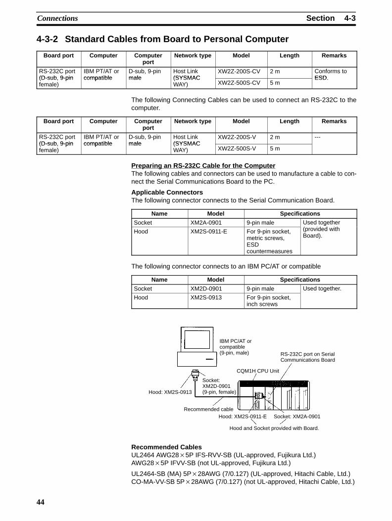
4-3-2 Standard Cables from Board to Personal Computer
Board port Computer Computerport
Network type Model Length Remarks
RS-232C port(D-sub 9-pin
IBM PT/AT orcompatible
D-sub, 9-pinmale
Host Link(SYSMAC
XW2Z-200S-CV 2 m Conforms toESD(D-sub, 9-pin
female)compatible male (SYSMAC
WAY) XW2Z-500S-CV 5 mESD.
The following Connecting Cables can be used to connect an RS-232C to thecomputer.
Board port Computer Computerport
Network type Model Length Remarks
RS-232C port(D-sub 9-pin
IBM PT/AT orcompatible
D-sub, 9-pinmale
Host Link(SYSMAC
XW2Z-200S-V 2 m ---(D-sub, 9-pinfemale)
compatible male (SYSMACWAY) XW2Z-500S-V 5 m
Preparing an RS-232C Cable for the ComputerThe following cables and connectors can be used to manufacture a cable to con-nect the Serial Communications Board to the PC.
Applicable ConnectorsThe following connector connects to the Serial Communication Board.
Name Model Specifications
Socket XM2A-0901 9-pin male Used together( id d i hHood XM2S-0911-E For 9-pin socket,
metric screws,ESDcountermeasures
g(provided withBoard).
The following connector connects to an IBM PC/AT or compatible
Name Model Specifications
Socket XM2D-0901 9-pin male Used together.
Hood XM2S-0913 For 9-pin socket,inch screws
g
IBM PC/AT orcompatible(9-pin, male)
Hood: XM2S-0913
Socket: XM2D-0901(9-pin, female)
Recommended cable
RS-232C port on SerialCommunications Board
CQM1H CPU Unit
Hood: XM2S-0911-E Socket: XM2A-0901
Hood and Socket provided with Board.
Recommended CablesUL2464 AWG28�5P IFS-RVV-SB (UL-approved, Fujikura Ltd.)AWG28�5P IFVV-SB (not UL-approved, Fujikura Ltd.)
UL2464-SB (MA) 5P�28AWG (7/0.127) (UL-approved, Hitachi Cable, Ltd.)CO-MA-VV-SB 5P�28AWG (7/0.127) (not UL-approved, Hitachi Cable, Ltd.)

4-4SectionHost Link Communications
45
4-4 Host Link Communications
4-4-1 ProtocolHost Link communications are executed by means of an exchange of com-mands and responses between the host computer and the PC. The command orresponse data that is transferred in one exchange is known as a frame and oneframe can contain up to 131 characters of data.
The frame formats for Host Link commands transmitted from the host computerand responses returned from the PC are described below. The PC automaticallyreturns an ASCII-code response when it receives an ASCII-code commandfrom the host computer. The host computer must have a program that controlsthe transmission and reception of the commands and responses.
When transmitting a command from the host computer, prepare the commanddata in the format shown below.
x 101@
FCS
x 100� ↵
Node No. Headercode
Text Terminator
The header code and text depend on the Host Link command being transmitted.When a compound command is transmitted, there will be a second sub-headercode.
The FCS (Frame Check Sequence) code is calculated at the host computer andset in the command frame. The FCS calculation is described later in this section.
The command frame may be up to 131 characters long. A command of 132 char-acters or more must be divided into more than one frame. To split the command,use a carriage return delimiter (↵ , CHR$(13)) instead of a terminator. A termina-tor must be used at the end of the last frame.
When dividing commands such as WR, WL, WC, or WD that execute write op-erations, be careful not to divide into separate frames data that is to be writteninto a single word. You must divide frames so that they coincide with the divisionsbetween words.
Item Function
@ An “@” symbol must be placed at the beginning of every command.
DestinationNode No.
Identify the PCs by the Host Link node numbers (0 to 31) set in DM6558 and DM 6553 of the PC Setup.
Header code Set the 2-character command code.
Text Set the command parameters.
FCS Set a 2-character Frame Check Sequence code.
Terminator Set two characters, “�” and the carriage return (CHR$(13)) toindicate the end of the command.
A normal response from the PC is returned in the format shown below. Prepare aprogram at the host so that the response data can be interpreted and processed.
@ x 101 x 100 x 161 x 160
FCS
� ↵
Node No. Headercode
End code Text Terminator
The header code and text depend on the Host Link command that was received.The end code indicates the completion status of the command (e.g., whether ornot an error has occurred).
Command Frame Format
Normal Response FrameFormat

4-4SectionHost Link Communications
46
When the response is longer than 131 characters, it will be divided into morethan one frame. A carriage return delimiter (↵ , CHR$(13)) instead of a terminatorwill automatically be set at the end of the frame. A terminator will be set at the endof the last frame.
Item Function
@ An “@” symbol is placed at the beginning of every response.
Local HostLink NodeNo.
The PC’s Host Link node number set in DM 6553 or DM 6558 ofthe PC Setup.
Header code The 2-character command code is returned.
End code The status of command execution is returned (normal end code).
Text The results of the command are returned.
FCS The 2-character Frame Check Sequence code is returned.
Terminator Two characters, “�” and the carriage return (CHR$(13)) indicate theend of the response.
An error response from the PC is returned in the format shown below. Prepare aprogram at the host so that the response data can be interpreted and processed.
@ x 101 x 100 x 161 x 160
FCS
� ↵
Node No. Headercode
End code Terminator
The header code and text depend on the Host Link command that was received.The end code indicates the completion status of the command (e.g., whether ornot an error has occurred).
Item Function
@ An “@” symbol is placed at the beginning of every response.
Local HostLink NodeNo.
The PC’s Host Link node number set in DM 6553 or DM 6558 ofthe PC Setup.
Header code The 2-character command code is returned.
End code The status of command execution is returned (error code).
FCS The 2-character Frame Check Sequence code is returned.
Terminator Two characters, “�” and the carriage return (CHR$(13)) indicate theend of the response.
When a frame is transmitted, an FCS code is placed just before the delimiter orterminator in order to check whether an error has occurred in the transmission.The FCS is 8-bit data converted into two ASCII characters. The 8-bit data is theresult of an EXCLUSIVE OR performed on the data from the beginning of theframe until the end of the text in that frame (i.e., just before the FCS). Calculatingthe FCS each time a frame is received and checking the result against the FCS
Error Response FrameFormat
FCS (Frame CheckSequence)

4-4SectionHost Link Communications
47
that is included in the frame makes it possible to check for data errors in theframe.
FCS
� ↵01 R R 0@ 0 0 1 4 2
TextNode No. Header code
FCS calculation range
Terminator
@ 40 0100 0000EOR
1 31 0011 0001EOR
0 30 0011 0000EOR
R 52 0101 0010
1 31 0011 00010100 0010↓ ↓ Converted to hexadecimal.4 2 Handled as ASCII characters.
ASCII code
Calculationresult
The right to send a frame is called the “transmission right.” The Unit that has thetransmission right is the one that can send a frame at any given time. The trans-mission right is traded back and forth between the host computer and the PCeach time a frame is transmitted. An example sequence for multiframe commu-nications between the host computer and PC is described below. Multiframecommunications are handled by exchanging delimiters and then using termina-tors to indicate the last frame.
• The host computer sets a delimiter at the end of the first command frame andtransmits the frame.
• When the PC receives the delimiter, it returns the same delimiter to the hostcomputer.
• After receiving the delimiter from the PC, the host computer transmits the nextframe.
• Delimiters are used to send the rest of the frames.
• When the host computer sends the last command frame, it sets a terminator atthe end.
• When the PC receives a frame with a terminator, it sends the response.
• If there was more than one response frame, delimiters would be used here too.
Delimiter
Text
@ Unit No.Header code
FCSDelimiter
Frame 1 (command)
Text
FCSDelimiter
TerminatorFCS
Text
End codeHeader code@ Unit No.
Frame 2 (command)
Frame (response)
Delimiter
Text
FCSTerminator
Frame 3 (command)
Hostcomputer
PC
CommunicationsSequence
4-4SectionHost Link Communications
48
The TXD(––) instruction can be used to transmit data from the PC’s data area tothe host computer. There is no response from the host computer. The TXD(––)instruction will be executed after the response has been transmitted if TXD(––)is executed while a response to a Host Link command is being returned to thehost computer.
No response
Text
@ Unit No.Header code
FCSTerminator
Hostcomputer
PC
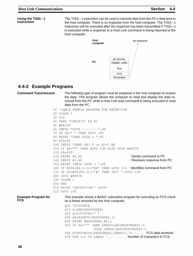
4-4-2 Example ProgramsThe following type of program must be prepared in the host computer to receivethe data. This program allows the computer to read and display the data re-ceived from the PC while a Host Link read command is being executed to readdata from the PC.
10 ’CQM1H SAMPLE PROGRAM FOR EXCEPTION20 CLOSE 130 CLS40 OPEN ”COM:E73” AS #150 �KEYIN60 INPUT ”DATA – –––––– –”,S$70 IF S$=” ” THEN GOTO 19080 PRINT ”SEND DATA = ”;S$90 ST$=S$100 INPUT ”SEND OK? Y or N?=”,B$110 IF B$=”Y” THEN GOTO 130 ELSE GOTO �KEYIN120 S$=ST$130 PRINT #1,S$ ’ Sends command to PC140 INPUT #1,R$ ’ Receives response from PC150 PRINT ”RECV DATA = ”;R$160 IF MID$(R$,4,2)=”EX” THEN GOTO 210 ’ Identifies command from PC170 IF RIGHT$(R$,1)<>” �” THEN S$=” ”:GOTO 130180 GOTO �KEYIN190 CLOSE 1200 END210 PRINT ”EXCEPTION!! DATA”220 GOTO 140
This example shows a BASIC subroutine program for executing an FCS checkon a frame received by the host computer.
400 *FCSCHECK410 L=LEN(RESPONSE$) 420 Q=0:FCSCK$=” ”430 A$=RIGHT$(RESPONSE$,1)440 PRINT RESPONSE$,A$,L450 IF A$=”*” THEN LENGS=LEN(RESPONSE$)-3 ELSE LENGS=LEN(RESPONSE$)-2460 FCSP$=MID$(RESPONSE$,LENGS+1,2) ’ FCS data received. . . . 470 FOR I=1 TO LENGS ’ Number of characters in FCS. . . . . . . . . . .
Using the TXD(––)Instruction
Command Transmission
Example Program forFCS

4-4SectionHost Link Communications
49
480 Q=ASC(MID$(RESPONSE$,I,1)) XOR Q490 NEXT I500 FCSD$=HEX$(Q)510 IF LEN(FCSD$)=1 THEN FCSD$=”0”+FCSD$ ’ FCS result520 IF FCSD$<>FCSP$ THEN FCSCK$=”ERR”530 PRINT”FCSD$=”;FCSD$,”FCSP$=”;FCSP$,”FCSCK$=”;FCSCK$540 RETURN
Note 1. Normal reception data includes the FCS, delimiter or terminator, and so on.When an error occurs in transmission, however the FCS or some other datamay not be included. Be sure to program the system to cover this possibility.
2. In this program example, the CR code (CHR$(13)) is not entered for RE-SPONSE$. When including the CR code, make the changes in lines 430and 450.
This example shows a program for using the RS-232C port in the Host Linkmode to transmit 10 bytes of data (DM 0000 to DM 0004) to a computer. FromDM 0000 to DM 0004, “1234” is stored in every word.
The default values are assumed for all of the PC Setup (i.e., the RS-232C port isused in Host Link mode, the node number is 00, and the standard communica-tions parameters are used.)
@TXD(––)
DM 0000
#0100
#0010
00100 20105
If SR 20105 (the Transmission Ready Flag) isON when IR 00100 turns ON, ten bytes ofdata (DM 0000 to DM 0004) will be trans-mitted.
The transmitted data will appear on the hostcomputer’s screen as follows, assuming thetext being sent is “1234” in all specified words:@00EX1234123412341234123459*CR
The PC Setup has a setting that can be used to enable CTS control. If CTS con-trol is enabled, processing will be placed on standby until the CS input turns ONafter the RS output ON signal is sent for a transmission from the Serial Commu-nications Board. Connect the RS output from the host to the CS input on theBoard and perform flow control at the host.
TXD(––) ApplicationExample
Communications ControlSignals andCommunications Timing
4-4SectionHost Link Communications
50
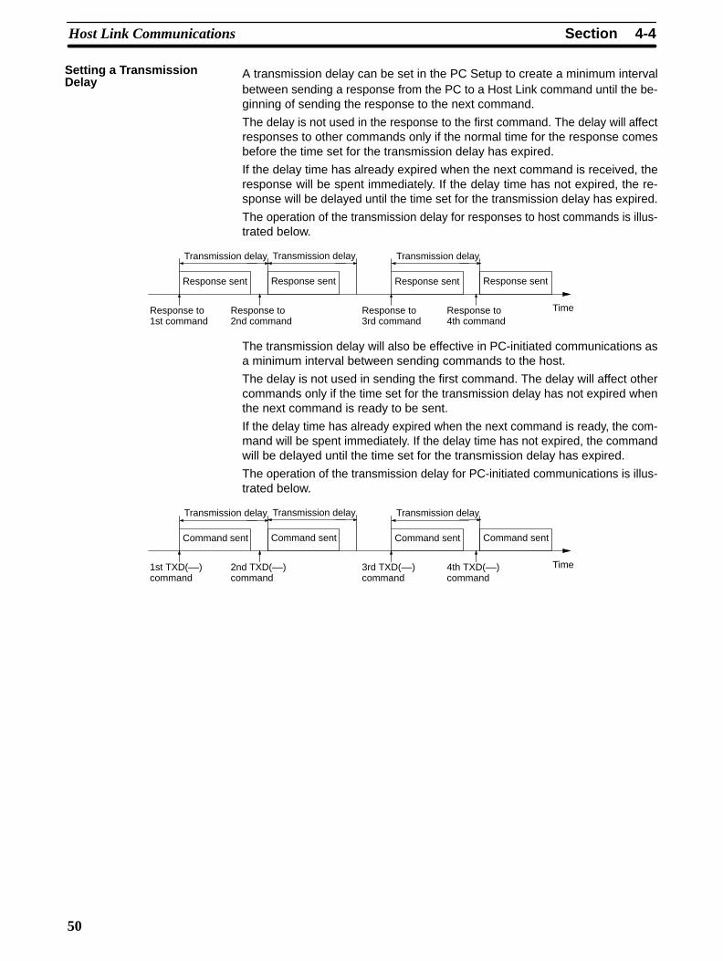
A transmission delay can be set in the PC Setup to create a minimum intervalbetween sending a response from the PC to a Host Link command until the be-ginning of sending the response to the next command.
The delay is not used in the response to the first command. The delay will affectresponses to other commands only if the normal time for the response comesbefore the time set for the transmission delay has expired.
If the delay time has already expired when the next command is received, theresponse will be spent immediately. If the delay time has not expired, the re-sponse will be delayed until the time set for the transmission delay has expired.
The operation of the transmission delay for responses to host commands is illus-trated below.
Response sent
Transmission delay
Response to1st command
Response to2nd command
Response sent
Transmission delay
Response sent
Transmission delay
Response to3rd command
Response to4th command
Response sent
Time
The transmission delay will also be effective in PC-initiated communications asa minimum interval between sending commands to the host.
The delay is not used in sending the first command. The delay will affect othercommands only if the time set for the transmission delay has not expired whenthe next command is ready to be sent.
If the delay time has already expired when the next command is ready, the com-mand will be spent immediately. If the delay time has not expired, the commandwill be delayed until the time set for the transmission delay has expired.
The operation of the transmission delay for PC-initiated communications is illus-trated below.
Command sent
Transmission delay
1st TXD(––)command
2nd TXD(––)command
Command sent
Transmission delay
Command sent
Transmission delay
3rd TXD(––)command
4th TXD(––)command
Command sent
Time
Setting a TransmissionDelay
4-4SectionHost Link Communications
51
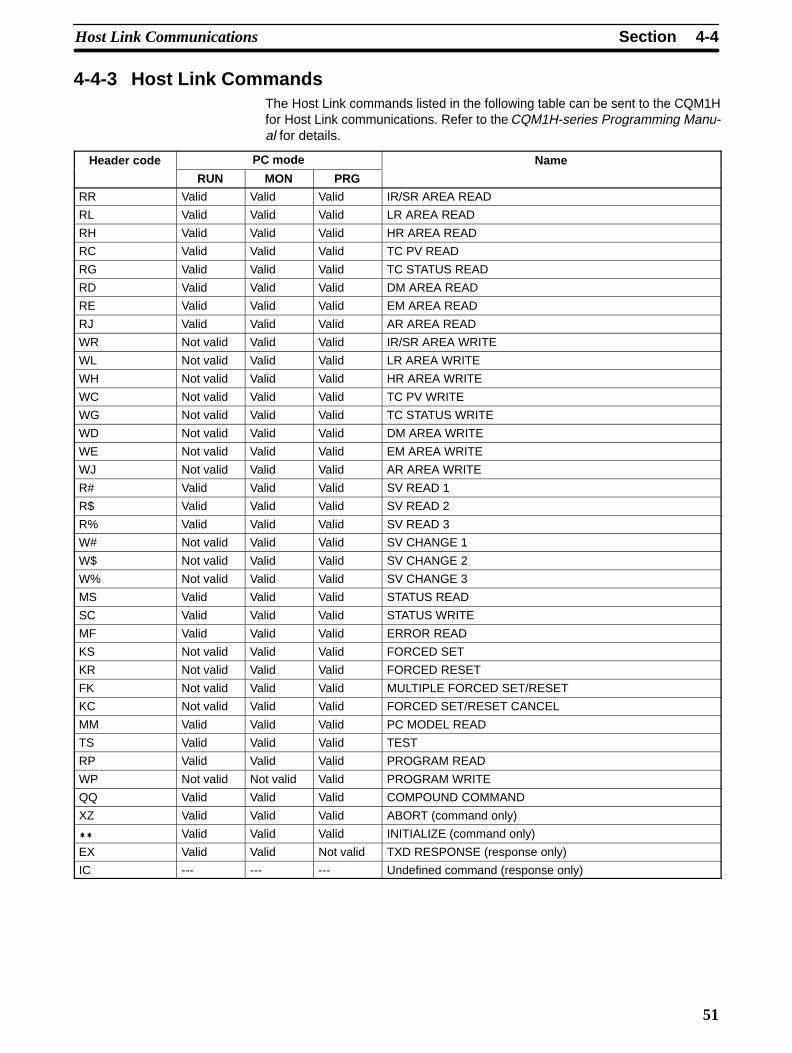
4-4-3 Host Link CommandsThe Host Link commands listed in the following table can be sent to the CQM1Hfor Host Link communications. Refer to the CQM1H-series Programming Manu-al for details.
Header code PC mode Name
RUN MON PRG
RR Valid Valid Valid IR/SR AREA READ
RL Valid Valid Valid LR AREA READ
RH Valid Valid Valid HR AREA READ
RC Valid Valid Valid TC PV READ
RG Valid Valid Valid TC STATUS READ
RD Valid Valid Valid DM AREA READ
RE Valid Valid Valid EM AREA READ
RJ Valid Valid Valid AR AREA READ
WR Not valid Valid Valid IR/SR AREA WRITE
WL Not valid Valid Valid LR AREA WRITE
WH Not valid Valid Valid HR AREA WRITE
WC Not valid Valid Valid TC PV WRITE
WG Not valid Valid Valid TC STATUS WRITE
WD Not valid Valid Valid DM AREA WRITE
WE Not valid Valid Valid EM AREA WRITE
WJ Not valid Valid Valid AR AREA WRITE
R# Valid Valid Valid SV READ 1
R$ Valid Valid Valid SV READ 2
R% Valid Valid Valid SV READ 3
W# Not valid Valid Valid SV CHANGE 1
W$ Not valid Valid Valid SV CHANGE 2
W% Not valid Valid Valid SV CHANGE 3
MS Valid Valid Valid STATUS READ
SC Valid Valid Valid STATUS WRITE
MF Valid Valid Valid ERROR READ
KS Not valid Valid Valid FORCED SET
KR Not valid Valid Valid FORCED RESET
FK Not valid Valid Valid MULTIPLE FORCED SET/RESET
KC Not valid Valid Valid FORCED SET/RESET CANCEL
MM Valid Valid Valid PC MODEL READ
TS Valid Valid Valid TEST
RP Valid Valid Valid PROGRAM READ
WP Not valid Not valid Valid PROGRAM WRITE
QQ Valid Valid Valid COMPOUND COMMAND
XZ Valid Valid Valid ABORT (command only)
�� Valid Valid Valid INITIALIZE (command only)
EX Valid Valid Not valid TXD RESPONSE (response only)
IC --- --- --- Undefined command (response only)

4-4SectionHost Link Communications
52
4-4-4 End CodesThe response (end) codes listed in the following table are returned in the re-sponse frame for Host Link commands. When two or more errors occur, the endcode for the first error will be returned.
Endcode
Contents Probable cause Corrective measures
00 Normal completion No problem exists. ---
01 Not executable in RUNmode
The command that was sent cannot beexecuted when the PC is in RUN mode.
Check the relation between thecommand and the PC mode.
02 Not executable in MON-ITOR mode
The command that was sent cannot beexecuted when the PC is in MONITORmode.
03 UM write-protected The PC’s UM is write-protected. Turn OFF pin 1 of the CPU Unit’sDIP switch (SW1).
04 Address over The program address setting in an read orwrite command is above the highest programaddress.
Check the program.
13 FCS error The FCS is wrong. Check the FCS calculation meth-od. If there was influence fromnoise, transfer the commandagain.
14 Format error The command format is wrong, or a com-mand that cannot be divided has been di-vided, or the frame length is smaller than theminimum length for the applicable command.
Check the format and transfer thecommand again.
15 Entry number data error The data is outside of the specified range ortoo long.
Hexadecimal data has not been specified.
Correct the data and transfer thecommand again.
16 Command not supported The operand specified in an SV Read or SVChange command does not exist in the pro-gram.
Check search data or the searchstarting point.
18 Frame length error The maximum frame length of 132 bytes wasexceeded.
If the frame exceeds 280 bytes, the Recep-tion Overflow Flag will be turned ON andthere will not be a response.
Check the command and divide itinto multiple frames if necessary.
19 Not executable The read SV exceeded 9,999, or an I/Omemory batch read was executed whenitems to read were not registered for com-pound command.
Register items to read before at-tempting batch read.
23 User memory protected The UM is write-protected. Turn OFF the write-protection
A3 Aborted due to FCS error intransmission data
An FCS error occurred in the second or laterframe, or there were two bytes or less ofdata in an intermediate or final frame for mul-tiple writing.
Correct the command data andtransfer the command again.
A4 Aborted due to format errorin transmission data
The command format did not match thenumber of bytes in the second or later frame.
A5 Aborted due to entry num-ber data error in transmis-sion data
There was an entry number data error in thesecond or later frame, a data length error, ordata was not set in hexadecimal.
A8 Aborted due to frame lengtherror in transmission data
The length of the second and later framesexceeded the maximum of 128 bytes.

4-5SectionChanges from Previous Products
53
A response will not be received with some errors, regardless of the command.These errors are listed in the following table.
Error PC operation
Parity, overrun, or framing error duringcommand reception. (Same even forcommands address to other Units.)
The Communications Error Flag will be turned ON, an error code willbe registered, and receptions will be reset. (The error will be clearedautomatically if communications restart normally.)
The Communications Error Flags are as follows:Peripheral port: AR 0812Built-in RS-232C port: AR 0804Serial Communications Board port 1: IR 20104, Serial Communications Board port 2: IR 20112
A command is received that does not have the@ character at the beginning of the first frame.
The command will be discarded.
Incorrect node number (Not a local unit or over31)
The command will be discarded.
The data in an intermediate or final frame formultiframe writes is 2 bytes or longer.
An FCS error will occur.
4-5 Changes from Previous ProductsThere are differences between Host Link Systems created using the CQM1H-series Serial Communications Boards in comparison to Host Link Systemscreated with Host Link Units and CPU Units in other PC product series. Thesedifferences are described in this section.
4-5-1 RS-232C PortsTake the following differences into consideration when changing from an exist-ing Host Link System to one using an RS-232C port on a CQM1H-series CPUUnit or Serial Communications Boards.
Previousd
Model number Changes required for CQM1H-series productproducts Wiring Other
C-series HostLink Units
3G2A5-LK201-E
C500-LK203
3G2A6-LK201-E
The connector has beenchanged from a 25-pin to a9-pin connector.
The CQM1H-seriesproducts do not support theST1, ST2, and RT signalsand wiring them is notrequired.
The following changes are necessary forsystems that sync with ST1, ST2, and RT.
Synchronized transfers will no longer bepossible.
Half-duplex transmissions will be possiblewith the CQM1H-series product, but the hostcomputer’s communications program,hardware, or both will need to be altered.
The following changes are necessary forsystems that did not sync with ST1, ST2,and RT.
It may be possible to use the host computerprograms without alteration as long as thesame communications settings (e.g., baudrate) are used. It may be necessary, however,to change programs to allow for different textlengths in frames or different CQM1Hcommand specifications. (See note.)
C200H-LK201 The connector has beenchanged from a 25-pin to a9-pin connector.
It may be possible to use the host computerprograms without alteration as long as thesame communications settings (e.g., baudrate) are used. It may be necessary, however,to change programs to allow for different textlengths in frames or different CQM1Hcommand specifications. (See note.)

4-5SectionChanges from Previous Products
54
Previousproducts
Changes required for CQM1H-series productModel numberPreviousproducts OtherWiring
Model number
C-series CPUUnits
SRM1
CPM1
CPM1A
CPM2A/CPM2C
CQM1-CPU��-E
C200HS-CPU��-E
C200HX/HG/HE-CPU��-E
C200HW-COM��-E
No changes have beenmade in wiring.
It may be possible to use the host computerprograms without alteration as long as thesame communications settings (e.g., baudrate) are used. It may be necessary, however,to change programs to allow for differentCQM1H command specifications.
CS1-series CPUUnit
CS1G/H-CPU�� No changes have beenmade in wiring.
It may be possible to use the host computerprograms without alteration as long as the
i ti tti ( b dCS1-seriesSerialCommunicationsBoard or Unit
CS1W-SCB21/41CS1W-SCU21
No changes have beenmade in wiring.
g gsame communications settings (e.g., baudrate) are used. It may be necessary, however,to change programs to allow for differentCQM1H command specifications.
CVM1 orCV-series CPUUnits
CVM1/CV-CPU�� No changes have beenmade in wiring.
It may be possible to use the host computerprograms without alteration as long as thesame communications settings (e.g., baudrate) are used. It may be necessary, however,to change programs to allow for differentCQM1H command specifications.
CVM1 orCV-series HostLink Unit
CV500-LK201 Port 1:The connector has beenchanged from a 25-pin to a9-pin connector.
Port 2 set for RS-232C:The SG signal has beenchanged from pin 7 to pin 9.
The following changes are necessary forhalf-duplex transmissions that use CD.
Check the system for timing problems whenusing SEND(90), RECV(98), or CMND(––) toinitiate communications from the PC or timingproblems in sending commands from the hostcomputer. If necessary, switch to full-duplextransmissions.
The following changes are necessary forfull-duplex transmissions that do not useCD.
Half-duplex It may be possible to use the hostcomputer programs without alteration as longas the same communications settings (e.g.,baud rate) are used. It may be necessary,however, to change programs to allow fordifferent CQM1H command specifications.
Note The number of words that can be read and written per frame (i.e., the textlengths) when using C-mode Host Link commands is different for C-series HostLink Units and CQM1H-series Serial Communications Boards. A host computerprogram previously used for C-series Host Link Units may not function correctlyif used for CQM1H-series PCs. Check the host computer program before using itand make any corrections required to handle different frame text lengths.
4-5SectionChanges from Previous Products
55
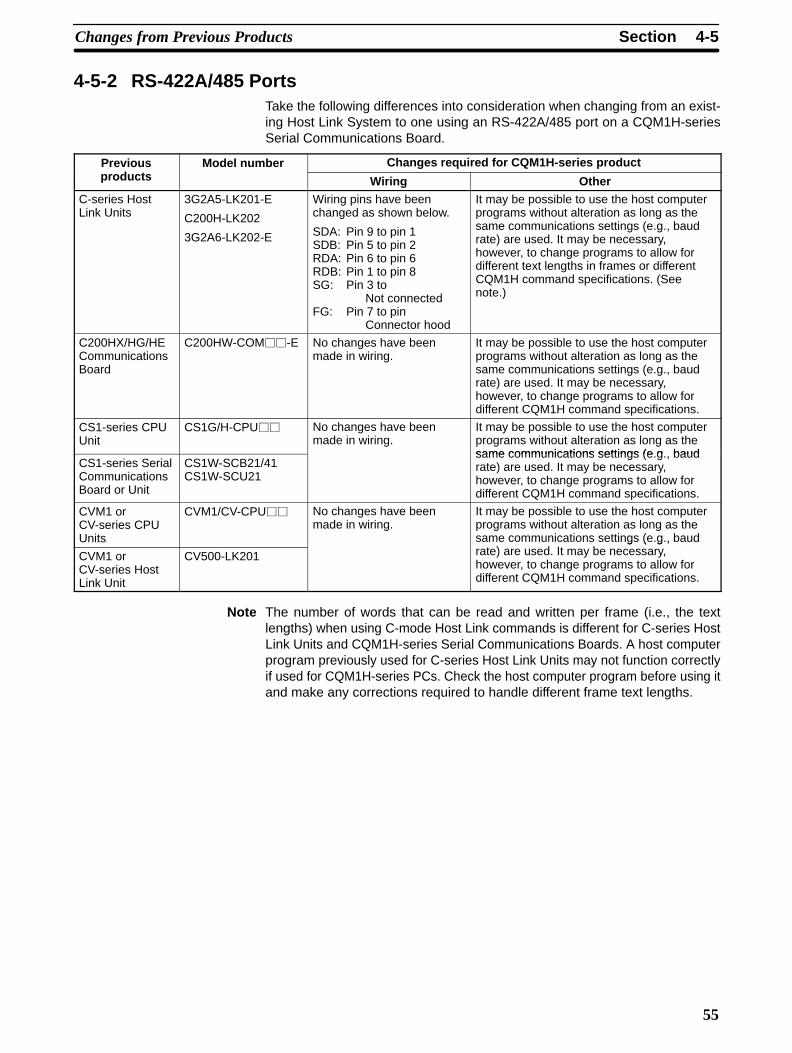
4-5-2 RS-422A/485 PortsTake the following differences into consideration when changing from an exist-ing Host Link System to one using an RS-422A/485 port on a CQM1H-seriesSerial Communications Board.
Previousd
Model number Changes required for CQM1H-series productproducts Wiring Other
C-series HostLink Units
3G2A5-LK201-E
C200H-LK202
3G2A6-LK202-E
Wiring pins have beenchanged as shown below.
SDA: Pin 9 to pin 1SDB: Pin 5 to pin 2RDA: Pin 6 to pin 6RDB: Pin 1 to pin 8SG: Pin 3 to
Not connectedFG: Pin 7 to pin
Connector hood
It may be possible to use the host computerprograms without alteration as long as thesame communications settings (e.g., baudrate) are used. It may be necessary,however, to change programs to allow fordifferent text lengths in frames or differentCQM1H command specifications. (Seenote.)
C200HX/HG/HECommunicationsBoard
C200HW-COM��-E No changes have beenmade in wiring.
It may be possible to use the host computerprograms without alteration as long as thesame communications settings (e.g., baudrate) are used. It may be necessary,however, to change programs to allow fordifferent CQM1H command specifications.
CS1-series CPUUnit
CS1G/H-CPU�� No changes have beenmade in wiring.
It may be possible to use the host computerprograms without alteration as long as thesame communications settings (e g baud
CS1-series SerialCommunicationsBoard or Unit
CS1W-SCB21/41CS1W-SCU21
same communications settings (e.g., baudrate) are used. It may be necessary,however, to change programs to allow fordifferent CQM1H command specifications.
CVM1 orCV-series CPUUnits
CVM1/CV-CPU�� No changes have beenmade in wiring.
It may be possible to use the host computerprograms without alteration as long as thesame communications settings (e.g., baud
t ) d It bCVM1 orCV-series HostLink Unit
CV500-LK201
g ( g ,rate) are used. It may be necessary,however, to change programs to allow fordifferent CQM1H command specifications.
Note The number of words that can be read and written per frame (i.e., the textlengths) when using C-mode Host Link commands is different for C-series HostLink Units and CQM1H-series Serial Communications Boards. A host computerprogram previously used for C-series Host Link Units may not function correctlyif used for CQM1H-series PCs. Check the host computer program before using itand make any corrections required to handle different frame text lengths.