section 3: septic tanks - waternsw - · pdf filesection 3: septic tanks 3. ... step 3...
TRANSCRIPT

Section 3:Septic Tanks
3. Septic Tanks

Design and Installation of On-site Wastewater Systems
27
3. Septic Tanks
3.1 Design .........................................................................................28
3.2 Installation....................................................................................29
3.3 Testing.........................................................................................37
3.4 Inspection ....................................................................................37
3.5 Operation .....................................................................................37
3.6 Common technical issues ..............................................................41
3.7 Case study ...................................................................................41
A septic tank provides the primary treatment of wastewater from a dwelling. It is often used together with other treatment measures such as in an aerated wastewater treatment system or with a pump well that pumps the clarified primary treated effluent for disposal. Primary treatment in a septic tank involves the following mainly physical (but also some chemical and biological) processes, which are further described below: • sedimentation (solids) • flotation (scum) • clarification • anaerobic digestion (organic material).
A septic tank must be able to retain the maximum 24 hour design flow to optimise settling and moderate peak flows. A correctly sized septic tank can remove approximately 25 to 35% of the Biochemical Oxygen Demand (BOD5) load and more than 60% of the suspended solids load from raw wastewater. Solids are stored in the base of the primary tank and liquids are discharged for further treatment and/or disposal. Floating material (scum) typically accumulates on the surface providing an airtight seal creating anaerobic conditions. Figure 3.1 shows a typical cross section of a septic tank.
Figure 3.1 Cross section of a typical septic tank
27

Design and Installation of On-site Wastewater Systems
28
Sedimentation
Sedimentation is achieved by settling in the still tank conditions, and is helped by the flocculation of suspended particles into larger aggregates. Sludge collects at the base of the tank. Whilst a long flow path in the tank from inlet to outlet helps with sedimentation, tanks with shorter flow paths may be baffled. The baffles will help keep the settled solids upstream of the baffle and create a still zone downstream to further help with settling before discharge. It is better for inflow to the tank to be gentle to avoid disturbing already settled solids. This is achieved by avoiding surge flows, having steep gradients from the source to the tank, and by fitting an inlet tee to moderate flow at the entry to the tank.
Flotation
Residues (oils and grease, surfactants, other low density materials) rise to the surface of tank and form a scum layer. Scum is kept in the tank by the inverted outlet pipe or baffle. The scum layer helps create an anaerobic environment for organic solids to breakdown.
Clarification Settled wastewater is kept in the middle layer of the tank. Tanks are appropriately sized to allow for maximum solids settling. Effluent is drawn from the clarified liquid between the sludge and scum layers for further treatment and/or disposal.
Anaerobic digestion Anaerobic microbes break down the organic material kept at the base of the tank. Organic material is converted to stable compounds and gases (eg carbon dioxide, methane and hydrogen sulphide). The retained sludge is mainly ligneous (woody) material that is difficult to decompose and will continue to accumulate. It will need to be removed every three to five years.
3.1 Design Septic tanks must be designed according to ‘AS/NZS 1546.1:2008 On-site Domestic Wastewater Treatment Units Septic Tanks’. In NSW any proprietary septic tank under 10,000 litres must be accredited by NSW Health. Larger tanks may be designed and produced on location but they must comply with AS/NZS 1546.1:2008. NSW Health requires all tanks more than 2,500 litres to be baffled. All septic tanks must include an outlet filter. Accredited tanks are listed on the NSW Health website www.health.nsw.gov.au/publichealth/environment /water/waste_water.asp.
Sizing
A septic tank must be able to deal with the peak daily hydraulic load for at least 24 hours plus an allowance for accumulated sludge. A tank that is too small could allow solids to pass on to the next treatment phase. The Sydney Catchment Authority requires at least a 3,000 litre tank in almost all circumstances. This may be increased according to the number of bedrooms in a proposed dwelling or where the dwelling includes a spa bath. For sizing, refer to AS/NZS 1547:2012.
Site considerations
When choosing the tank location you must consider the various site constraints such as slope, grade and stability. A septic tank must be positioned on a stable, level base. A septic tank on a sloping site may need a stormwater diversion drain to prevent
–
28

Design and Installation of On-site Wastewater Systems
29
stormwater inundation. It may also need a pump well to pump effluent from the tank to an upslope effluent management area.
Tank location The location of a tank should be decided in consultation with the licensed plumber. It will depend on the fall and drainage outlets needed from the dwelling. Some constrained sites may need to locate tanks under driveways and other structures, such as decks and patios. In these cases, the manufacturer can provide a maximum load rating for the tank and a structural engineer must be consulted to ensure the tank has the structural capacity to handle the anticipated vertical load.
Designer accountability The designer must provide a Design Producer Statement, where the design is warranted by the designer, to ensure a high level of accountability. Appendix 2 includes an example of a Design Producer Statement.
3.2 Installation
Septic tank installation must comply with the manufacturer’s recommendations, ‘AS/NZS 3500.2:2003 Plumbing and Drainage Part 2 Sanitary Plumbing and Drainage’ and Council requirements. Checklist 3.1 helps system installers and council inspectors ensure the septic tank has been correctly installed. The following extra steps provide details not included in the checklist.
Step 1 Transporting tanks All proprietary tanks should be manufactured and transported to the installation site as one complete unit to preserve their structural integrity. Tank manufacturers can recommend suitable transport methods based on the tank type. Tanks should be kept upright and not laid on their side.
Step 2 Lifting and moving tanks
All tanks should only be lifted or moved using the lifting points shown on the outside of the tank. Tanks should not be lifted by the rim or lid/inspection holes. Do not use a forklift unless the lift arms reach completely underneath the tank to support the base.
Step 3 Excavating and preparing the hole for tanks
The depth of the hole for the tank depends on the fall of the pipe to the tank and the distance from the installed tank to the wastewater source. The tank should be installed so that the lid remains at least 100 millimetres above final ground level to stop stormwater entering the tank. The hole must be clear of roots and foreign matter. The excavation must allow space to fix tank anchors as per the manufacturer’s recommendations, if required. The base of the hole must have a clean bed of compacted sand at least 50 millimetres deep. The sand surface must be flat and level.
Step 4 Installing tanks Tanks should be carefully lowered into the hole and not dropped. Use lifting equipment to adjust the position of the tank. The tank inlet should be in line with the inlet pipes.
Step 5 Connecting pipes and fittings
Connect the tank inlet to the inlet pipe using a 100 millimetre rubber sleeve and secure it according to plumbing practices detailed in AS/NZS 3500:2003 and the
29
Design and Installation of On-site Wastewater Systems
30
manufacturer’s recommendations. Methods to secure pipe work into inlets and outlets vary with the different tanks, which may include concrete, fibreglass or polyethylene.
Step 6 Sealing pipes and lids Tank lids and inlet and outlet connections should be sealed with an appropriate durable and flexible sealant to avoid stormwater entering the tank.
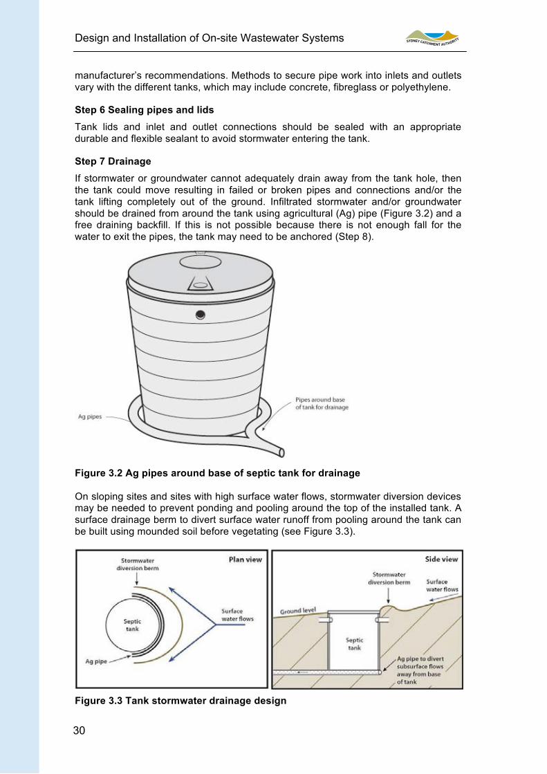
Step 7 Drainage If stormwater or groundwater cannot adequately drain away from the tank hole, then the tank could move resulting in failed or broken pipes and connections and/or the tank lifting completely out of the ground. Infiltrated stormwater and/or groundwater should be drained from around the tank using agricultural (Ag) pipe (Figure 3.2) and a free draining backfill. If this is not possible because there is not enough fall for the water to exit the pipes, the tank may need to be anchored (Step 8).
Figure 3.2 Ag pipes around base of septic tank for drainage
On sloping sites and sites with high surface water flows, stormwater diversion devices may be needed to prevent ponding and pooling around the top of the installed tank. A surface drainage berm to divert surface water runoff from pooling around the tank can be built using mounded soil before vegetating (see Figure 3.3).
Figure 3.3 Tank stormwater drainage design
30

Design and Installation of On-site Wastewater Systems
31
Step 8 Attaching ground anchors (if required)
If groundwater levels are high and/or drainage cannot be installed, ground anchors may be needed (Figure 3.4). The size and installation of ground anchors must comply with ‘AS/NZS 1546:2008 3.2.2 Anchorage’.
Loops connecting the anchors to the tank must be fitted when the tank is installed. Each side of the tank must be anchored using a piece of filled pipe attached to the tank by durable ties made from stainless steel cable. These ties are fitted to the anchor points on the tank and have a loop in the other end at excavation base level.
Backfilling covers the anchors securing the tank in the ground. To prepare ground anchors you must: • fill the ground anchors (100 millimetre uPVC sewer pipe) with sand and cap
the ends. Attach at least two anchors to a tank, parallel to each other, on opposite sides of the tank. Use more anchors if the soil is prone to saturation. The anchors should be at least as long as the diameter of the tank
• secure the free end loops of cable around the ends of each ground anchor, with two cables to each anchor
• fit a stainless steel shackle in each cable through pre-drilled holes in vertical ribs of each tank and secure
• hang all ground anchors level beside the tank approximately 150 millimetres from the bottom of the excavation, with cables fully secured and all fastenings securely tightened. Sand filled anchors help tighten the cables and ensure maximum effect. Never run cables through the anchor pipes as they will cut when under loads.
Figure 3.4 Ground anchors
Alternatively, a hydrostatic flange and anchor collar may be fitted. An ‘L’ shaped anchor collar section at least 65 millimetres wide and 6 millimetres thick should be built and fixed to the outside circumference of the tank with durable material protected from corrosion. The collar can be continuous around the circumference or in at least two sections each at least 600 millimetres long and fixed on opposite sides of the tank. For a vertical cylindrical tank, the flange is fixed less than 300 millimetres from the base. For a horizontal cylindrical tank the flange is situated along the line of the greatest horizontal perimeter.
31

Design and Installation of On-site Wastewater Systems
32
Step 9 Backfill
Do not start backfilling until connections and anchoring are all complete. Some regulatory authorities require an inspection before backfilling.
Step 10 Vegetation
The area around the tanks should be suitably vegetated with non invasive plant species. Some plants can penetrate even a sealed tank and pipe work. Planting suitable species around a tank, particularly on sloping sites, is important to minimise soil erosion from the excavated area around the tanks.
Checklist 3.1 outlines a comprehensive range of items to inspect for new septic tank installations. Councils and installers can use the checklist as part of their installation report. Installation checklists for land application systems are in Sections 8 (Amended soil mounds), 9 (Sand mounds), 10 (Absorption trenches and beds), 11 (Evapotranspiration absorption beds), 12 (Surface irrigation) and 13 (Subsurface irrigation).
System Design
Better communication between the designer and installer is achieved by the designer preparing a System Design that explains critical details of the design to the installer. It describes and quantifies the design and shows the appropriate layout and configuration of the system with appropriate plans and sketches. Appendix 3 includes an example of a System Design.
Finally, the installer must provide an Installation Certificate that certifies that the installation is as described in the relevant sections of the System Design. Appendix 4 includes an example of an Installation Certificate.
32

Design and Installation of On-site Wastewater Systems
33
Checklist 3.1 Septic tank installation inspection for installers and Councilinspectors (Based on ‘Consortium of Institutes for Decentralised Wastewater Treatment – Installation Checklists’,Iowa State University, Midwest Plan Service. Ames, IA)
Owners name:
Address:
Installation date:
Type of tank (tick all applicable eg septic tank plus pump well. NB: where the system involves a septictank and a pump well, the minimum NSW Health requirement is for the pump well to have a capacity of2,000 L).
□ Septic tank □ Pump well □ Collection /holding well
□ Other
Tank No. Tank No. Tank No.
Manufacturer (Tank 1): Model #:
Material
□Plastic/poly
□Concrete
□Fibreglass
□Other
Comment:
Manufacturer (Tank 2): Model #:
□Plastic/poly
□Concrete
□Fibreglass
□Other
Comment:
Specified or calculated tank capacity of each tank(1) L (2) L
Tank dimensions (as provided on manufacturer’s design specification sheet)Tank (1) Tank (2)
Exterior dimensions (diameter & height) mm mm
Interior dimensions mm mm
Exterior height of inlet invert mm mm
Exterior height of outlet invert mm mm
Effective depth mm mm
Tank seamLocation □ N/A □ Mid □ Top
Comment:
Has the tank been appropriately sealed?
□ Butylmastic □ Butyl tapewrap
□ Two-partepoxy
□ Two-partepoxy andstainlessfasteners
□ Other
Tank structural integrity verified before setting □ Yes □ No □ N/A
Checklist 3.1 Septic tank installation inspection for installers and Council inspectors (Based on ‘Consortium of Institutes for Decentralised Wastewater Treatment – Installation Checklists’, Iowa State University, Midwest Plan Service. Ames, IA)
Owners name:
Address:
Installation date:
Type of tank (tick all applicable eg septic tank plus pump well. NB: where the system involves a septic tank and a pump well, the minimum NSW Health requirement is for the pump well to have a capacity of 2,000 L).
□ Septic tank □ Pump well □ Collection / holding well
□ Other
Tank No. Tank No. Tank No.
Manufacturer (Tank 1): Model #:
Material
□ Plastic/poly
□ Concrete
□ Fibreglass
□ Other
Comment:
Manufacturer (Tank 2): Model #:
□ Plastic/poly
□ Concrete
□ Fibreglass
□ Other
Comment:
Specified or calculated tank capacity of each tank (1) L (2) L
Tank dimensions (as provided on manufacturer’s design specification sheet) Tank (1) Tank (2)
Exterior dimensions (diameter & height) mm mm
Interior dimensions mm mm
Exterior height of inlet invert mm mm
Exterior height of outlet invert mm mm
Effective depth mm mm
Tank seam Location □ N/A □ Mid □ Top
Comment:
Has the tank been appropriately sealed?
□ Butylmastic □ Butyl tape wrap
□ Two-part epoxy
□ Two-part epoxy and stainless fasteners
□ Other
Tank structural integrity verified before setting □ Yes □ No □ N/A
33

Design and Installation of On-site Wastewater Systems
34
Excavation / setting tanks Location of tanks:
Verify required inlet / outlet elevations □ Yes □ No □ N/A Groundwater present in excavation □ Yes □ No □ N/A Dewatering performed □ Yes □ No □ N/A Bottom of excavation
Level □ Yes □ No □ N/A Free of rock and debris □ Yes □ No □ N/A Bedding material Description:
Depth cm
Free of large rocks, debris □ Yes □ No □ N/A Compacted □ Yes □ No □ N/A Structural integrity of tanks verified
Tank installed level □ Yes □ No □ N/A Tank oriented correctly □ Yes □ No □ N/A Free standing above ground
Flat bed □ Yes □ No □ N/A Compacted □ Yes □ No □ N/A Verify required inlet and outlet elevations □ Yes □ No □ N/A Flotation prevention
Buoyancy calculations provided on design □ Yes □ No □ N/A Anti-flotation implemented
Tank collar □ Yes □ No □ N/A Anchor weight □ Yes □ No □ N/A Other / Comment
Backfill Backfill material:
Compacted □ Yes □ No □ N/A Free of debris and large rocks □ Yes □ No □ N/A
34

Design and Installation of On-site Wastewater Systems
Piping
Piping in appropriate sequence (inlet/outlet) □ Yes □ No □ N/A Inlet mm Outlet / supply line mm
Pipe specifications (material and nominal diameter) Return line mm Electrical conduit mm
Joints in excavated area □ Yes □ No □ N/A Pipe sealing Pipes appropriately sealed (including electrical conduit for pump well) □ Yes □ No □ N/A Type of sealant Inlet
Outlet / supply line
Return line (if installed)
Electrical conduit
Recirculation device □ Yes □ No □ N/A Type of device
Baffles / compartments Inlet baffle type
Outlet baffle type
Effluent screen model # and manufacturer:
Types of baffles: □ Poly/Plastic □ Concrete □ Fibreglass Installation by: □ Manufacturer □ Contractor Verify air passage □ Yes □ No □ N/A Tank access & venting
Access location and size Inlet mm
Outlet mm
Centre mm
Access risers required □ Yes □ No
Sealant used in tank / riser connections □ Yes □ No Venting □ Yes □ No □ N/A Through plumbing stack □ Yes □ No □ N/A Tank vent (describe):
35 35

Design and Installation of On-site Wastewater Systems
36
Proprietary filter □ Yes □ No □ N/A Filter manufacturer and model #:
Tank water tightness testing □ Yes □ No □ N/A Comments, actions or repairs required: (Where a response in the above Checklist needs extra information or action, specify the action plan and/or the process to fix the problem, or specify an alternative that is being offered)
Service provider:
Title:
Contact number: Signature: Date:
36

Design and Installation of On-site Wastewater Systems
37
3.3 Testing
Pumps Where pumps are used in a separate external pump well or an internal pump chamber, they should be clean water tested before commissioning to ensure they achieve the desired head for the proposed operation.
Water tightness
All joints should be sealed with flexible sealant according to the manufacturer’s instructions to ensure water tightness. Secure the septic tank lid and inspection openings to provide a watertight seal.
3.4 Inspection
Council should inspect the tank and all associated pipe and drainage work before backfilling to ensure all components are correctly positioned and installed according to ‘PCA 2004 Plumbing Code of Australia’. Council should make a final installation inspection to ensure the system complies with all consent conditions before issuing an approval to operate the system. Checklist 3.2 provides a list of items to inspect for operating septic systems that council inspectors and system owners can use to ensure their system continually operates as required.
3.5 Operation
Pumps
Different system designs can use different types of pumps. The most common are surface mounted pumps with an inlet in a separate pump well. These systems pump the clarified primary effluent, with minimal solids, to an effluent management area. Where a collection well is used with a pump-to-sewer system, there will be a grinder or macerator pump in the septic chamber of the tank. These pumps are designed to pump both liquid and solids to a secondary treatment system.
Do not use a macerator or grinder pump to transfer effluent directly from a septic tank to an effluent management area, as the latter will block and fail due to the solid content in the effluent.
Outlet filter The outlet filter should be inspected every three months and cleaned when necessary. Clean the outlet filter by hosing it off (Figure 3.5), ideally, into a bucket or directly into the septic tank. It is important to only hose off gross solids and not the biofilm that accumulates on filter surfaces. The filter does not need to be completely clean.
37

Design and Installation of On-site Wastewater Systems
38
Figure 3.5 Cleaning the outlet filter
Desludging
Sludge levels in septic tanks should be inspected regularly as part of the maintenance schedule and the sludge depth measured with an appropriate device (eg ‘Sludge Judge’ (Figure 3.6) or ‘Sonic Sludge Stick’ (Figure 3.7)). AS/NZS 1547:2012 provides guidance about how often to remove sludge (roughly once every three to five years). A licensed contractor should remove the sludge. When sludge is removed from a septic tank, about 10% of the original contents should be kept in the tank to help an appropriate bacterial population regenerate for ongoing treatment.
Once pumped out, the tank should be refilled with water to its normal operating level to protect against undue upward pressure from high groundwater. If the groundwater level near the tank is known to be high, solids should be pumped from the tank at the same time as refilling it with clean water. Once pumped out, replace all inspection openings and seal the tank lid with flexible sealant.
Figure 3.6 ‘Sludge Judge’ Figure 3.7 ‘Sonic Sludge Stick’
38

39
Checklist 3.2 Operating septic system inspection for Council inspectors
Slope % Tank diameter mm
No. ofbedrooms
Nearestwatercourse m
No. of residents No. of tanks
Water source □ Tank □Bore/reticulated
Tank volume(s)L
System age Nearest house m
Is there vegetation present? □ Yes □ No
Is there native vegetation dieback? □ Yes □ No
Do you need to remove vegetation around and in the tank toimprove access for maintenance? □ Yes □ No
Is there weed infestation? □ Yes □ No
Is there localised flood potential? □ Yes □ No
Is there erosion potential? □ Yes □ No
Tank
Is there any indication of cracks, staining or leaks aroundthe perimeter of the septic tank and/or pump well and/orholding tank?
□ Yes □ No
Are there any gaps between the tank and the lid? □ Yes□ No
Is the tank lid suitable for the tank? □ Yes□ No
Does the tank have easily accessible inspection caps? □ Yes □ No
Are the inspection caps present and unbroken? □ Yes □ No
Has the primary septic tank been desludged in the last 5years? □ Yes □ No □ Unknown
Does the tank need desludging (is the sludge level high ornear the bottom of the inlet)? □ Yes □ No
Is any air vent attached to the septic tank / holding well ina functional state? □ Yes □ No □ N/A
Is the tank in good condition (no cracks, leaks / damagedlids/ walls)? □ Yes □ No
Do tanks need urgent repair / replacement due to majorstructural failure or undersizing? □ Yes □ No
Does the tank have a scum or crust layer? □ Yes □ No
Design and Installation of On-site Wastewater Systems
Checklist 3.2 Operating septic system inspection for Council inspectors Slope % Tank diameter mm
No. of bedrooms
Nearest watercourse m
No. of residents No. of tanks
Water source □ Tank □ Bore/reticulated
Tank volume(s) L
System age Nearest house m
Is there vegetation present? □ Yes □ No
Is there native vegetation dieback? □ Yes □ No
Do you need to remove vegetation around and in the tank to improve access for maintenance? □ Yes □ No
Is there weed infestation? □ Yes □ No
Is there localised flood potential? □ Yes □ No
Is there erosion potential? □ Yes □ No
Tank
Is there any indication of cracks, staining or leaks around the perimeter of the septic tank and/or pump well and/or holding tank?
□ Yes □ No
Are there any gaps between the tank and the lid? □ Yes □ No
Is the tank lid suitable for the tank? □ Yes □ No
Does the tank have easily accessible inspection caps? □ Yes □ No
Are the inspection caps present and unbroken? □ Yes □ No
Has the primary septic tank been desludged in the last 5 years? □ Yes □ No □ Unknown
Does the tank need desludging (is the sludge level high or near the bottom of the inlet)? □ Yes □ No
Is any air vent attached to the septic tank / holding well in a functional state? □ Yes □ No □ N/A
Is the tank in good condition (no cracks, leaks / damaged lids/ walls)? □ Yes □ No
Do tanks need urgent repair / replacement due to major structural failure or undersizing? □ Yes □ No
Does the tank have a scum or crust layer? □ Yes □ No
39

Design and Installation of On-site Wastewater Systems
40
Has the outlet filter been cleaned recently? □ Yes □ No □ N/A
Pumps
Does the pump operate when needed? (trigger the float switches to check operation) □ Yes □ No □ N/A
Does the alarm work? □ Yes □ No □ N/A
Has the pump been serviced in the last 12 months? □ Yes □ No □ N/A
Pipes
Are the pipes connecting the septic tank, pump well and/or holding well, or septic tank and trench, functioning and installed correctly?
□ Yes □ No □ Unknown
Are there any unsealed pipes that allow untreated wastewater to escape? □ Yes □ No □ Unknown
Comments, actions or repairs required: (Where a response in the above Checklist needs extra information or action, specify the action plan and/or the process to fix the problem, or specify an alternative that is being offered)
Service provider:
Title:
Contact number: Signature: Date:
40

Design and Installation of On-site Wastewater Systems
41
3.6 Common technical issues
There are a number of common problems with septic tank installations including: • tanks rising out of the ground after rainfall this is most common for un-
anchored plastic or fibreglass tanks • baffles and inlet and outlet junctions removed, not installed (Figure 3.8),
broken, or not connected to an effluent disposal system • pumping from the septic tank rather a separate pump well • high levels of sludge accumulating from inadequate maintenance (lack of
desludging) • undersized tanks relative to the hydraulic loads • poor drainage around the tank due to run-on, or because it is installed too low
into the ground.
Figure 3.8 Outlet pipe discharging directly onto open ground
3.7 Case study
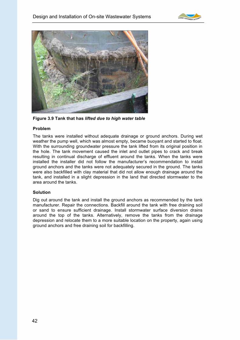
A septic tank and pump well were installed on a site prone to high groundwater levels. After significant rain the property owner noticed that the pump well was sitting higher out of the ground than when installed. The owner put some fill around the tank and thought it would be alright. A month later a council officer inspected the tanks and noticed the same tank sitting high out of the ground with ponded effluent and soggy ground around it (Figure 3.9).
-
41
Design and Installation of On-site Wastewater Systems
42
Figure 3.9 Tank that has lifted due to high water table
Problem
The tanks were installed without adequate drainage or ground anchors. During wet weather the pump well, which was almost empty, became buoyant and started to float. With the surrounding groundwater pressure the tank lifted from its original position in the hole. The tank movement caused the inlet and outlet pipes to crack and break resulting in continual discharge of effluent around the tanks. When the tanks were installed the installer did not follow the manufacturer’s recommendation to install ground anchors and the tanks were not adequately secured in the ground. The tanks were also backfilled with clay material that did not allow enough drainage around the tank, and installed in a slight depression in the land that directed stormwater to the area around the tanks.
Solution
Dig out around the tank and install the ground anchors as recommended by the tank manufacturer. Repair the connections. Backfill around the tank with free draining soil or sand to ensure sufficient drainage. Install stormwater surface diversion drains around the top of the tanks. Alternatively, remove the tanks from the drainage depression and relocate them to a more suitable location on the property, again using ground anchors and free draining soil for backfilling.
42